Embed Size (px)
Citation preview

LRL File No.: 130708 December 2013
Geotechnical InvestigationProposed New Commercial Building
1015 Dairy DriveOttawa, Ontario
Prepared for:
Drytech International Inc.92 Bentley Avenue
Ottawa, OntarioK2E 6T9
Attention: Mr. Eric Cameron P. EngVice President, MarGard Ltd.
LRL Associates Ltd.1-2884 Chamberland Street Tel: (613) 446-7777 or (877) 632-5664
Rockland, Ontario Website: www.LRL.caK4K 1M6 Fax: (613) 446-1427a
Geotechnical Investigation LRL File: 130708Proposed New Commercial Building December 20131015 Dairy Drive, Ottawa, Ontario Page i
LRL Associates Ltd.
TABLE OF CONTENTS1 INTRODUCTION ................................................................................................................ 1
2 PROJECT AND SITE DESCRIPTION ................................................................................ 1
3 PROCEDURE..................................................................................................................... 2
4 SUBSURFACE SOIL AND GROUNDWATER CONDITIONS ............................................ 3
4.1 Fill ............................................................................................................................... 3
4.2 Topsoil........................................................................................................................ 4
4.3 Silty Clay .................................................................................................................... 4
4.4 Groundwater .............................................................................................................. 4
5 GEOTECHNICAL CONSIDERATIONS .............................................................................. 5
5.1 Foundations ............................................................................................................... 5
5.2 Settlement .................................................................................................................. 6
5.3 Use of Structural Fill .................................................................................................. 6
5.4 Seismic ....................................................................................................................... 7
5.5 Potential for Soil Liquefaction .................................................................................. 7
5.6 Slab-on-grade Construction...................................................................................... 7
5.7 Frost Protection ......................................................................................................... 8
5.8 Foundation Drainage ................................................................................................. 8
5.9 Foundation Walls Backfill ......................................................................................... 8
5.10 Retaining Walls and Shoring..................................................................................... 9
5.11 Trees..........................................................................................................................11
6 POTENTIAL OF CORROSIVE ENVIRONMENT ...............................................................12
6.1 Sulphate Attack on Buried Concrete .......................................................................12
7 EXCAVATION AND BACKFILLING REQUIREMENTS ....................................................13
7.1 Excavation.................................................................................................................13
7.2 Groundwater Control................................................................................................13
7.1 Pipe Bedding Requirements ....................................................................................14
7.2 Trench Backfill ..........................................................................................................14
7.3 Reuse of On-Site Soils..............................................................................................15
8 SLOPE STABILITY ANALYSIS ........................................................................................15
8.1 Slope Description .....................................................................................................15
Geotechnical Investigation LRL File: 130708Proposed New Commercial Building December 20131015 Dairy Drive, Ottawa, Ontario Page ii
LRL Associates Ltd.
8.2 Assessment...............................................................................................................16
8.3 Recommendations....................................................................................................18
9 PAVEMENT DESIGN ........................................................................................................19
9.1 Paved Areas and Subgrade Preparation .................................................................20
10 INSPECTION SERVICES...............................................................................................21
11 REPORT CONDITIONS AND LIMITATIONS.................................................................21
TABLES
Table 1 Material Properties for Shoring and Permanent Wall Design………………..........9
Table 2 Material Properties for Shoring and Permanent Wall Design (Seismic) ............11
Geotechnical Investigation LRL File: 130708Proposed New Commercial Building December 20131015 Dairy Drive, Ottawa, Ontario Page iii
LRL Associates Ltd.
APPENDICES
Appendix A Test Pit Location Plan
Appendix B Test Pit Logs
Appendix C Laboratory Test Reports – Physical Tests
Appendix D Laboratory Certificate of Analysis – Chemical Tests
Appendix E Slope Stability Analysis Results
Appendix F Symbols and Terms Used in Test Pit Logs
Geotechnical Investigation LRL File: 130708Proposed New Commercial Building December 20131015 Dairy Drive, Ottawa, Ontario Page 1 of 22
LRL Associates Ltd.
1 INTRODUCTION
Drytech International Inc. retained the services of LRL Associates Ltd. (LRL) to carry out
a geotechnical investigation for a proposed new commercial building to be located at the
1015 Dairy Drive in Ottawa, Ontario.
The purpose of this investigation was to identify the subsurface conditions at the site by
means of a limited number of test pits, provide geotechnical recommendations with
regard to the design of foundations for the proposed building and to provide construction
considerations.
It is our understanding that the site development plan for this project will consist of the
construction of a one to three storey commercial structure with a slab-on-grade and no
basement. This new building would house the headquarters of Drytech International Inc.
and will contain a combination of office and warehouse spaces. Access lanes and
parking areas are also being proposed. Entrance to the site will be from Dairy Drive.
The new building will be serviced by municipal water and sewers.
Should there be any changes in the design features, which may relate to the guidelines
provided in the report, LRL Associates Ltd. should be advised in order to review the
report recommendations.
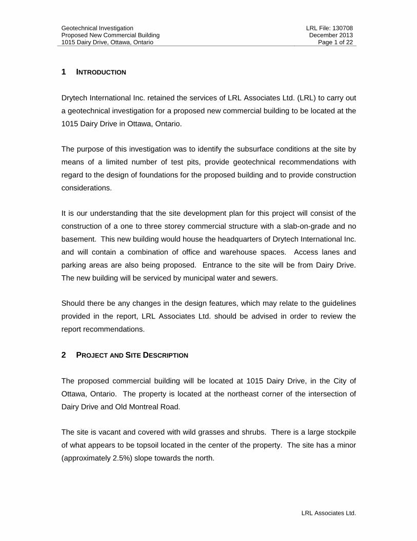
2 PROJECT AND SITE DESCRIPTION
The proposed commercial building will be located at 1015 Dairy Drive, in the City of
Ottawa, Ontario. The property is located at the northeast corner of the intersection of
Dairy Drive and Old Montreal Road.
The site is vacant and covered with wild grasses and shrubs. There is a large stockpile
of what appears to be topsoil located in the center of the property. The site has a minor
(approximately 2.5%) slope towards the north.
Geotechnical Investigation LRL File: 130708Proposed New Commercial Building December 20131015 Dairy Drive, Ottawa, Ontario Page 2 of 22
LRL Associates Ltd.
It is noted that there is a natural creek (Cardinal Creek) that flows east of the site within
a small valley. The crest of the slope of the west side of the valley is approximately 13m
from the east property line of the site and outlets into the Ottawa River,
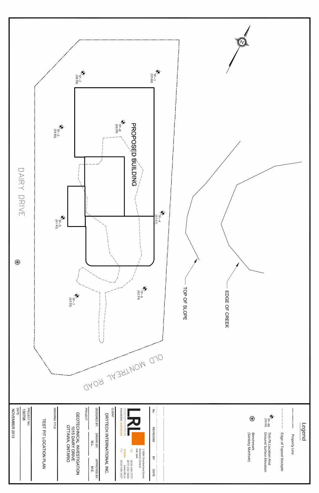
approximately1km north of the site. The locations of the completed tests pits, the
proposed building layout, topsoil stockpile and subject slope are shown on the Test Pit
Location Plan given in Appendix A of this report.
3 PROCEDURE
The fieldwork for this investigation was carried out on November 4th, 2013 at which time
eight (8) test pits (labelled TP-1 through TP-8) were put down close to and within the
proposed footprint of the building based on the layout given by the client. With
permission from the client, a manual auger hole was also completed in the subject slope
to confirm the soil stratigraphy. Prior to the fieldwork, the test pit locations were cleared
for any underground services and utilities. The test pits were advanced using a backhoe
excavator supplied and operated by Guy Courschesne Excavation Ltd.
Sampling of the overburden materials encountered in the test pits was carried out by
means of grab samples collected from the bucket of the backhoe while digging down to
depths of ranging from 1.8m – 4.6m bgs (below ground surface). Field vane
measurements were also taken within the test pits to evaluate the undrained shear
strength of the clay found on site. Grab samples were also collected from the test pits
for subsequent examination and analysis. The fieldwork was supervised throughout by
a member of our engineering staff who oversaw the digging of the test pits, in-situ
testing, cared for the samples obtained and logged the subsurface conditions
encountered within each of the test pit.
The ground surface elevations of the test pits were measured using a laser level. The
test pit elevations were referenced to an established elevation of a manhole found on
Dairy Drive, approximately 100m north of Old Montreal Road. The geodetic elevation of
the manhole was taken from the results of a topographic survey completed of the site by
Annis, O’Sullivan, Vollebekk Ltd.
Geotechnical Investigation LRL File: 130708Proposed New Commercial Building December 20131015 Dairy Drive, Ottawa, Ontario Page 3 of 22
LRL Associates Ltd.
Laboratory testing was also completed on soil samples collected as part of this
investigation. Physical laboratory tests on the clay were performed by Stantec
Laboratories, an accredited soils and materials testing lab. Several soil samples were
also submitted to Paracel Laboratories Ltd., an accredited chemical testing lab, for
chemical analyses.
4 SUBSURFACE SOIL AND GROUNDWATER CONDITIONS
The subsurface conditions encountered in the test pits were classified based on visual
and tactile examination of the materials recovered from the test pits and the results of
the in-situ and laboratory testing. The soil descriptions presented in this report are
based on commonly accepted methods of classification and identification employed in
geotechnical practice. Classification and identification of soil involves judgement and
LRL does not guarantee descriptions as exact, but infers accuracy to the extent that is
common in current geotechnical practice.
The subsurface soil conditions encountered at each test pit location are given in the Test
Pit Logs presented in Appendix B. The test pits indicate the subsurface conditions at
the specific test locations only. Boundaries between zones on the test pit logs are often
not distinct, but rather are transitional and have been interpreted.
A review of the geological maps for this site suggests that the site is underlain by
erosional terraces generally composed of silt and clay. The drift thickness for this area
would be approximately 15m to 25m. The following is a brief overview of the subsurface
conditions encountered at the test pits dug at this site.
4.1 Fill
Fill material was found directly at the surface in TP-3 and TP-5. The fill can be
described as being a heterogeneous mix of gravel, sand, silt and clay, brown in colour,
in a loose state of packing and moist. The thickness of the fill layer was found to be
approximately 400mm in both test pits.
Geotechnical Investigation LRL File: 130708Proposed New Commercial Building December 20131015 Dairy Drive, Ottawa, Ontario Page 4 of 22
LRL Associates Ltd.
4.2 Topsoil
It is noted that the site contains a very large stockpile (approximately 3m to 5m high) of
what appears to be topsoil. This was confirmed by digging out a small section of the
stockpile with the backhoe. Considering that no topsoil was found in the test pits
locations, it is assumed that this stockpile contains the native site topsoil.
The material was classified as topsoil based on colour and the presence of organic
materials and is intended as identification for geotechnical purposes only and does not
constitute a statement as to the suitability of this layer for cultivation and sustaining plant
growth.
4.3 Silty Clay
Clay was found in every test pit completed as part of this project. The clay is described as
being silty and is greyish brown in colour with minor red bands. The clay’s consistency is
a hard to very stiff (100kPa <Cu< 300kPa) at the surface becoming stiff (50kPa <Cu<
100kPa, where the lowest value obtained was 70kPa) approximately 2.8m to 3.8m below
ground surface. It is noted that the clay is weathered by frost at the surface for about
0.5m. All test pits were terminated within the clay deposit.
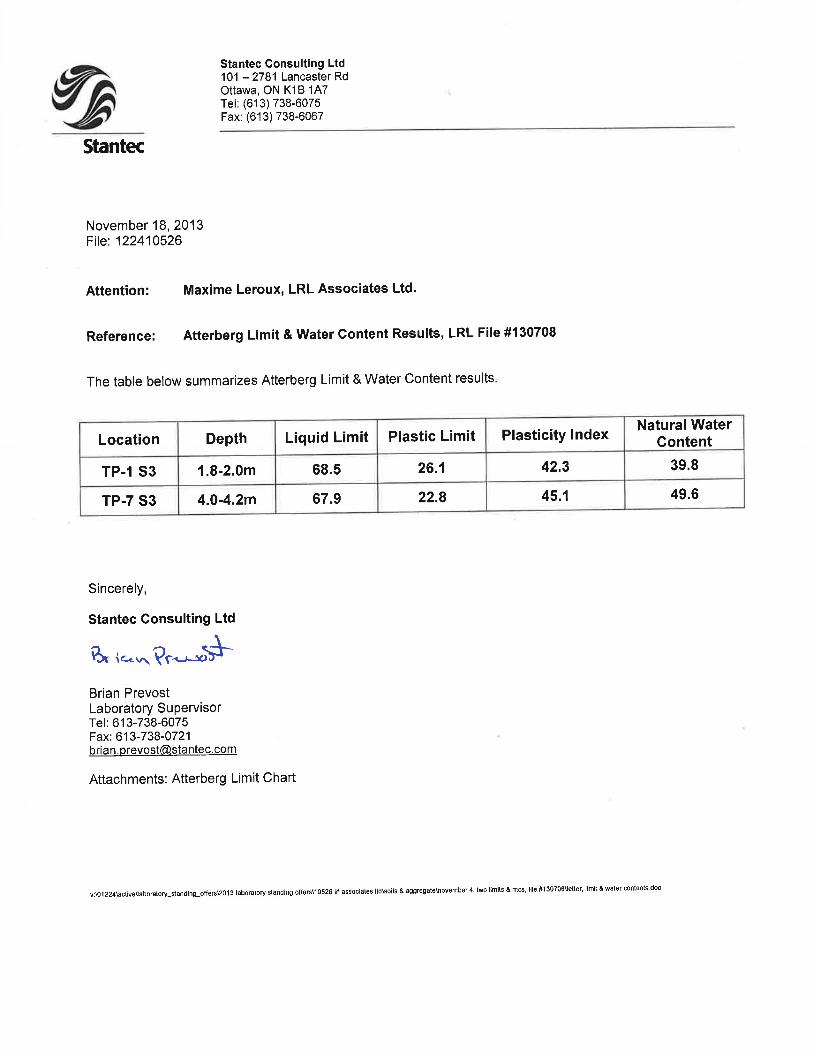
Atterberg limits and water content were performed on clay samples collected from TP-1
(S3) and TP-7 (S3) at an approximate depth of 1.9m and 4.1m bgs respectively. The
results revealed that the clay has a liquid limit ranging from 67.9% to 68.5%, a plastic
limit from 22.8% to 26.1%, a plasticity index from 39.8% to 45.1% and a moisture content
from 39.8% to 49.6%. According to the Unified Soil Classification System, this clay would
be classified as high plasticity clay (CH). The moisture content of the clay was found
above its plastic limit and below its liquid limit and increases with depth. The laboratory
result reports can be found in Appendix C of this report.
4.4 Groundwater
Prior to backfilling the test pits, standpipes were installed in TP-1, TP-3, TP-6 and TP-7 inorder to establish the static water level of the local groundwater. The static water levels
Geotechnical Investigation LRL File: 130708Proposed New Commercial Building December 20131015 Dairy Drive, Ottawa, Ontario Page 5 of 22
LRL Associates Ltd.
were measured using a water meter on November 7th, 2013. The level varies across thesite and is between 1.1m to 2.2m below ground surface. Due to the soil conditions, thisgroundwater is considered a perched seasonal water table found within the surficialfractured clay deposit and over the more impervious massive clay deposit. It is notedthat only minor groundwater seepages were observed in the open test pits and generallyoccurring at the interface of the fractured and massive clay. The water levelmeasurements are shown on the test pit logs presented in Appendix B.
It should be noted that this groundwater table can easily fluctuate with seasonal weather
conditions (i.e.: rainfall, droughts and spring thawing). In addition, it can be locally
affected by the presence of existing ditches and underground services trenches.
5 GEOTECHNICAL CONSIDERATIONS
5.1 Foundations
Based on the subsurface soil conditions encountered at this site, it is recommended that
foundations for the proposed new building be founded over the native, undisturbed silty
clay deposit or properly prepared and approved structural fill.
Conventional strip and column footings set over the native clay or properly prepared and
approved structural fill may be designed using a maximum allowable bearing pressure of
100kPa for serviceability limit state (SLS) and 150kPa for ultimate limit state (ULS)
factored bearing resistance. The allowable bearing capacity is based on a maximum
width of 1.5m for strip footings and/or on pad footings not exceeding 3.0m on any side.
The bearing capacity is also contingent on minimum founding depth of 0.5m (below the
weathered surficial clay) and a maximum founding depth of 1.5m below the existing
ground surface and a maximum allowable grade raise above the native of 1.2m.
Geotechnical Investigation LRL File: 130708Proposed New Commercial Building December 20131015 Dairy Drive, Ottawa, Ontario Page 6 of 22
LRL Associates Ltd.
If the above parameters cannot be met for the foundation design of the building, the
bearing capacity, founding depth or footing width will need to be revised. Should grade
raises be needed beyond the limitations given in this report, consideration should be
given to carrying out consolidation analyses on the clay, which may provide additional
allowance for grade raises. Another solution should larger grade raises be needed
would be using light-weight fill. Information on the use of light-weight fill can be provided
if this option is retained.
5.2 Settlement
The estimated total settlement of the foundations, designed using the recommended
serviceability limit state capacity value given herein as well as other recommendations
will be less than 25mm. The differential settlement between adjacent footings is
anticipated to be 20mm or less.
5.3 Use of Structural Fill
Where excavation below the underside of the footing is performed, considerations shall
be given to support the footings on structural fill. The structural fill shall be placed over
undisturbed native soils in layers not exceeding 200mm and compacted to 98% of its
Standard Proctor Maximum Dry Density (SPMDD). In order to allow the spread of load
beneath the footings and to prevent under mining during construction, the structural fill
must extend 1m beyond the outside edges of the footings and then outward and
downward at 1 horizontal to 1 vertical profile (or flatter) over a distance equal to the
depth of the structural fill below the footing. The recommended material to be used as
structural fill to support the footings shall consist of imported granular material meeting
Ontario Provincial Standards Specifications (OPSS) requirements for a Granular B Type
II, or an approved equivalent material.
Prior to placing any structural fill or to pouring the footings, it is required that any
disturbed soils along the base of the footings be removed and that the subgrade soils be
inspected and approved by the geotechnical engineer. Furthermore, the structural fill
must be tested to ensure that the specified compaction level was achieved.
Geotechnical Investigation LRL File: 130708Proposed New Commercial Building December 20131015 Dairy Drive, Ottawa, Ontario Page 7 of 22
LRL Associates Ltd.
5.4 Seismic
Based on the results of the geotechnical investigation and the relatively limited
information gathered from test pits with regards to the deeper soil deposits, the soil at
the site can be classified as a class “E” as per the Site Classification for Seismic Site
Response in the latest version of the Ontario Building Code. It is noted that a greater
seismic site response class may be obtained from carrying out seismic velocity testing
using a multichannel analysis of surface waves (MASW).
5.5 Potential for Soil Liquefaction
Clay soils are not considered prone to liquefaction and as such, liquefaction of the
underlying soil is not a concern for this construction.
5.6 Slab-on-grade Construction
Slab-on-grade construction will be acceptable over the native clay or approved structural
fill. Therefore, all organics, fill or otherwise deleterious material shall be removed from
the building’s footprint.
Any underfloor fill needed to raise the general floor grade shall consist of Granular B
Type I material or an approved equivalent, compacted to 95% of its standard proctor
maximum dry density (SPMDD). The final lift shall be compacted to 98% of its SPMDD.
A 200 mm layer of Granular A material shall be placed under the slab and compacted to
at least 98% of the SPMDD.
In order to further minimize and control cracking, the floor slab shall be provided with
wire mesh reinforcement and construction or control joints. The construction or control
joints should be spaced equal distance in both directions and should not exceed 4.5 m.
The wire mesh reinforcement shall be carried through the joints.
Geotechnical Investigation LRL File: 130708Proposed New Commercial Building December 20131015 Dairy Drive, Ottawa, Ontario Page 8 of 22
LRL Associates Ltd.
5.7 Frost Protection
Exterior footings and any footings located in unheated portions of the building shall be
protected against frost heaving by providing a minimum of 1.5m of earth cover under
snow covered surface or 1.8m under exposed surfaces (i.e. sidewalks, paved areas,
etc.), or its equivalent in insulation protection. LRL shall review the detailed design of
frost protection with the use of equivalent insulation prior to construction if this option is
chosen.
In the event that foundations are to be constructed during winter months, foundation
soils are required to be protected from freezing temperatures using suitable construction
techniques. Therefore, the base of all excavations should be insulated from freezing
temperature immediately upon exposure, until the time that heat can be supplied to the
building interior and footings have sufficient soil cover to prevent freezing of the
subgrade soils.
5.8 Foundation Drainage
Permanent perimeter drainage is not required considering that the building will not
contain a basement. In order to prevent the ponding of water adjacent to the foundation
walls, the roof water shall be controlled by a roof drainage system and the exterior grade
shall be sloped to shed water away from the walls.
5.9 Foundation Walls Backfill
To prevent possible foundation frost jacking, the backfill against foundation walls must
consist of free draining, non-frost susceptible material meeting OPSS Granular B - Type
I gradation requirements or an approved equivalent.
The foundation wall backfill should be compacted to 90% of its SPMDD using light
compaction equipment, where no loads will be set over top. The compaction shall be
increased to 95% under walkways, slabs or paved areas close to the foundation or
retaining walls. Backfilling against foundation walls should be carried out on both sides
of the wall at the same time where applicable.
Geotechnical Investigation LRL File: 130708Proposed New Commercial Building December 20131015 Dairy Drive, Ottawa, Ontario Page 9 of 22
LRL Associates Ltd.
5.10 Retaining Walls and Shoring
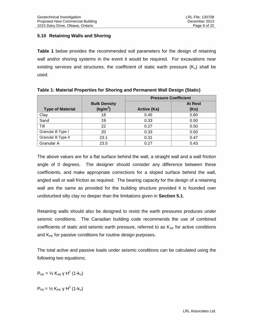
Table 1 below provides the recommended soil parameters for the design of retaining
wall and/or shoring systems in the event it would be required. For excavations near
existing services and structures, the coefficient of static earth pressure (Ko) shall be
used.
Table 1: Material Properties for Shoring and Permanent Wall Design (Static)
Type of MaterialBulk Density
(kg/m3)
Pressure Coefficient
Active (Ka)At Rest
(Ko)Clay 18 0.45 0.80Sand 19 0.33 0.50Till 22 0.27 0.50Granular B Type I 20 0.33 0.50Granular B Type II 23.1 0.31 0.47Granular A 23.5 0.27 0.43
The above values are for a flat surface behind the wall, a straight wall and a wall friction
angle of 0 degrees. The designer should consider any difference between these
coefficients, and make appropriate corrections for a sloped surface behind the wall,
angled wall or wall friction as required. The bearing capacity for the design of a retaining
wall are the same as provided for the building structure provided it is founded over
undisturbed silty clay no deeper than the limitations given in Section 5.1.
Retaining walls should also be designed to resist the earth pressures produces under
seismic conditions. The Canadian building code recommends the use of combined
coefficients of static and seismic earth pressure, referred to as KAE for active conditions
and KPE for passive conditions for routine design purposes.
The total active and passive loads under seismic conditions can be calculated using the
following two equations;
PAE = ½ KAE γ H2 (1-kV)
PPE = ½ KPE γ H2 (1-kV)
Geotechnical Investigation LRL File: 130708Proposed New Commercial Building December 20131015 Dairy Drive, Ottawa, Ontario Page 10 of 22
LRL Associates Ltd.
Where;
KAE = Active Earth Pressure Coefficient Combined Static and Seismic
KPE = Combined Static and Seismic Passive Earth Pressure Ccoefficient
H = Total Height of the Wall (m)
Kh = Horizontal Acceleration Coefficient
Kv = Vertical Acceleration Coefficient
γ = Bulk Density (kg/m3)
These equations are based on a horizontal slope behind the wall and a vertical back of
the retaining wall and zero wall friction. For this site, the following design parameters
were used to develop the recommended KAE and KPE values.
A = Zonal Acceleration Ratio = 0.2
Kh = Horizontal Acceleration Coefficient = 0.1
KV = Horizontal Acceleration Coefficient = 0.067
The above value of Kh corresponds to ½ of the A value and the value KV of corresponds
to 0.67 of the Kh value. The angle of friction between the soil and the wall has been set
at 0o to provide a conservative estimate.
The following Table 2 provides the parameters for seismic design of retaining structures.

Geotechnical Investigation LRL File: 130708Proposed New Commercial Building December 20131015 Dairy Drive, Ottawa, Ontario Page 11 of 22
LRL Associates Ltd.
Table 2: Material Properties for Shoring and Permanent Wall Design (Seismic)
Parameter OPSS Granular B Type IOPSS Granular A and
Granular B Type IIBulk Unit Weight, γ (kN/m3) 20 23.3Effective Friction Angle (degrees) 30 32Angle of Internal Friction Betweenwall and Backfill (degrees) 0 0
Yielding WallActive Seismic Earth PressureCoefficient (KAE) 0.37 0.33Height of the Application of PAEfrom the base of the wall as aration of its height (H) 0.36 0.37Passive Seismic Earth PressureCoefficient (KPE) 3.06 3.48Height of the Application of PPEfrom the base of the wall as aration of its height (H) 0.30 0.30
5.11 Trees
It should be noted that the silty clay soils underlying the sand at the site may be sensitive
to water depletion by trees of high water demand during periods of dry weather. When
trees draw water from the clay, the clay undergoes shrinkage which can result in
settlement of adjacent structures. Research carried out by the Institute for Research
Construction, formerly the Division of Building Research, of the National Research
Council of Canada, referenced as CBD-62. Trees and Buildings, published in February
1965, provides the following guideline:
“If trees are already growing on the building site, every effort should be made so to
locate the structure such that it conforms to the suggestions in the next paragraph. If this
cannot be done then, with natural reluctance trees that are going to be too close to the
building must be cut down and their root systems removed. It is far better that this should
be done and new trees planted appropriately than that aesthetic claims should over-rule
sound judgment with the possibility of damage to the building and the eventual inevitable
removal of the trees in any case. Care should be taken that the removed trees have not
already desiccated the clay, which may then swell under the changed environment.”
“If trees are to be planted as a part of the landscaping around the building, a good
working rule has been found to be that trees should preferably be planted no nearer a
building on shrinkable clay than the eventual height to which the tree may be expected
Geotechnical Investigation LRL File: 130708Proposed New Commercial Building December 20131015 Dairy Drive, Ottawa, Ontario Page 12 of 22
LRL Associates Ltd.
to grow. This rule may require modification if the topography around the building varies.
Even in its application, attention must be given to the differing transpiration
characteristics of trees”
6 POTENTIAL OF CORROSIVE ENVIRONMENT
6.1 Sulphate Attack on Buried Concrete
Three soil samples collected from TP-1 (S2), TP-5 (S2) and TP-7 (S1) were submitted to
Paracel Laboratories Ltd., an accredited chemical testing laboratory, for analysis on
sulphate content within silty clay deposit. The laboratory analysis revealed a maximum
measured sulphate concentration of 0.0015% (15 µg/g), 0.0013% (13 µg/g) and
0.0014% (14 µg/g) respectively for the three samples.
Based on the CAN/CSA-A23.1 standards (Concrete Materials and Methods of Concrete
Construction), a sulphate concentration of 0.1% (1000 µg/g) or less in soil falls within the
negligible category for sulphate attack on buried concrete. As such, buried concrete for
footings and foundation walls will not require any special additive to resist sulphate
attack and the use of normal Portland cement is acceptable. The laboratory Certificates
of Analysis can be found in Appendix D of this report.
6.2 Corrosion on Buried Steel
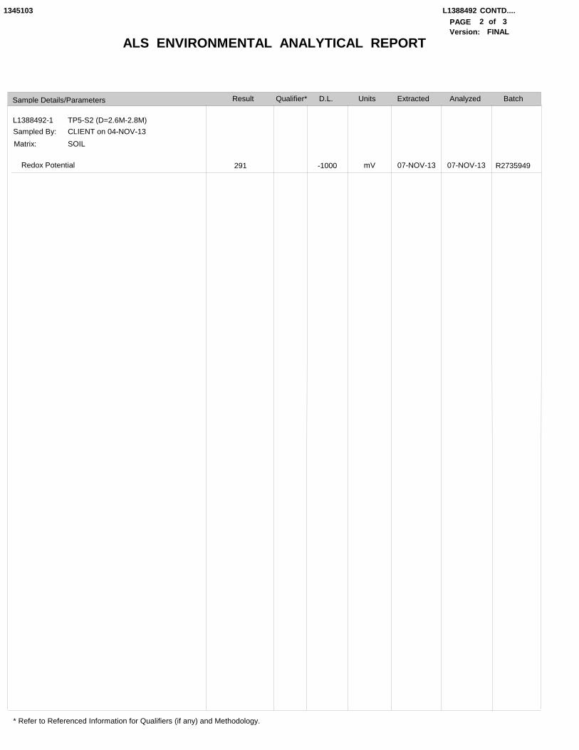
A soil sample (S-2) collected from TP-5 was submitted to Paracel laboratories Ltd. for
chemical analysis, which included pH, Resistivity, Chloride and Redox Potential. The
purpose of this testing was to assess the potential for corrosive environment on any
buried steel. The laboratory Certificates of Analysis are presented in Appendix D.
The potential for an aggressive corrosive soil environment was established by
comparing the test results for the above measured parameters to the standard provided
by the American Water Works Association (AWWA) C-105/A21.5-10. Based on the
noted standard, corrosion protection for buried steel with respect to cast iron pipes is
only required where a corrosivity index of 10 or greater is encountered. Based on the
results, the calculated corrosivity index was found to be 2 excluding sulphides (the
Geotechnical Investigation LRL File: 130708Proposed New Commercial Building December 20131015 Dairy Drive, Ottawa, Ontario Page 13 of 22
LRL Associates Ltd.
maximum value for sulphides is 3.5 which still bring the total below 10). As such, any
buried steel as part of this project would not require any special or specific corrosion
protection measures.
7 EXCAVATION AND BACKFILLING REQUIREMENTS
7.1 Excavation
It is anticipated that the depth of excavation for the building and underground services
will not extend below 3.5m bgs. The overburden soil encountered at this site consists
primarily of hard to very stiff clay becoming stiff with depth, generally below 2.8m.
According to the Ontario’s Occupational Health and Safety Act (OHSA), O. Reg. 527/00
and its amendments, the surficial overburden soil expected to be excavated at this site
can be classified as Type 2 for fully drained excavations. Therefore, shallow temporary
excavation in the overburden soil classified as Type 2 can be cut vertically for the first
1.2m of the excavation starting at the based followed by a slope of 1 horizontal to 1
vertical to the surface for a fully drained excavation and as per requirements of the
OHSA regulations.
Any excavated material stockpiled near an excavation or trench should be stored at a
distance equal to or greater than the depth of the excavation/trench and construction
equipment traffic should be limited near open excavation.
It the event that the aforementioned slopes are not possible to achieve due to space
restrictions, the excavation shall be shored according to OHSA O. Reg. 527/00 and its
amendments. A geotechnical engineer shall design and approve the shoring and
establish the shoring depth under the excavation profile. Refer to the parameters
provided in Table 1 and Table 2 in Section 5.10 for use in the design of any shoring
structures.
7.2 Groundwater Control
Based on the overburden soil encountered at this site (primarily silty clay), groundwater
seepage or infiltration from the native soils into the excavations during construction
Geotechnical Investigation LRL File: 130708Proposed New Commercial Building December 20131015 Dairy Drive, Ottawa, Ontario Page 14 of 22
LRL Associates Ltd.
should be minimal. Any groundwater seepage or infiltration entering the excavation
should be removed from the excavation by pumping from sumps within the excavations.
Surface water runoff into the excavation should be minimized and diverted away from
the excavation.
7.1 Pipe Bedding Requirements
It is anticipated that the underground services required as part of this project will be
founded over very stiff clay. Bedding, thickness of cover material and compaction
requirements for sewers and watermains shall conform to the manufacture’s design
requirements and to the requirements and detail installations outlined in the Ontario
Provincial Standard Specifications (OPSS), drawings OPSD 802-030 or 802.031 Class B
or Class C for concrete pipes and OPSD 802.01 for flexible pipes as well as any
requirements from the City of Ottawa.
Any sub-excavation of disturbed soil should be completed and replaced with a Granular
B Type II laid in loose lifts no more than 200mm thick and compacted to 98% of SPMDD.
7.2 Trench Backfill
All service trenches should be backfilled using compactable material, free of organics,
debris and large cobbles or boulders. Acceptable native materials (silty clay from the
crust) should be used as backfill between the roadway subgrade level and the depth of
seasonal frost penetrations (i.e. 1.8m below finished grade) in order to reduce the
potential for differential frost heaving between the new excavated trench and the
adjacent section of roadway. Where native backfill is used, it should match the native
materials exposed on the trench walls. Backfill below the zone of seasonal frost
penetration could consist of either acceptable native material or imported granular
material conforming at minimum to OPSS Granular B Type I.
To minimize future settlement of the backfill and achieve an acceptable subgrade for the
roadway, the trench should be compacted in maximum 300mm thick lifts to at least 95
SPMDD. The specified density may be reduced where the trench backfill is not located
within or in close proximity to existing roadways or any other structures.
Geotechnical Investigation LRL File: 130708Proposed New Commercial Building December 20131015 Dairy Drive, Ottawa, Ontario Page 15 of 22
LRL Associates Ltd.
For trench carried out in already paved areas, transitions should be constructed to
ensure that proper compaction is achieved between any new pavement structure and
the existing pavement structure to minimise potential future differential settlement
between the existing and new pavement structure. The transition should start at the
subgrade level and extend to the underside of the asphaltic concrete level (if any) at a 1
horizontal to 1 vertical slope. This is especially important where trench boxes are used
and where no side slopes is provided to the excavation. Where asphaltic concrete is
present, it should be cut back to a minimum of 150mm from the edge of the excavation
to allow for proper compaction between the new and existing pavement structures.
7.3 Reuse of On-Site Soils
The existing surficial overburden soils consist mostly of silty clay. The clay is considered
to be frost susceptible and should not be used as backfill material directly against
foundation walls or underneath concrete slabs. However, the clay crust (first 3.0m)
could be reused as general backfill material (service trenches, general
landscaping/backfilling), if it can be compacted according to the specifications outlined
herein at the time of construction. Any imported material shall conform to OPSS
Granular B - Type I.
It shall be noted that the adequacy of any material for reuse as backfill will depend on its
water content at the time of its use and on the weather conditions prevailing prior and
during that time. Therefore, all excavated materials to be reused shall be stockpiled in a
manner that will prevent any significant changes in their moisture content, especially
during wet conditions. Any excavated materials proposed for reuse should be stockpiled
in a manner to promote drying and should be inspected and approved for reuse by a
geotechnical engineer.
8 SLOPE STABILITY ANALYSIS
8.1 Slope Description
As stated herein, a small creek (Cardinal Creek) flows in a south to the north direction on
the property to the east of the site under investigation. The creek has cut a deep ravine
Geotechnical Investigation LRL File: 130708Proposed New Commercial Building December 20131015 Dairy Drive, Ottawa, Ontario Page 16 of 22
LRL Associates Ltd.
into the terrain that extends about 8m to 9m below the general grades of the site under
investigation (Elevation of approximately 61m – 62m) based on the results of the
topographic survey completed for the site. The crest of the west slope under
investigation is approximately 13.5m east of the property line as established by the fence
line of the site in question, at the closest point of the meander of the creek.
In general, the crest of the slope is located at elevation ±61m at its closest point to the
proposed development, the toe of the steep section of the slope is at elevation ±55m
and the elevation of the water of the creek is at ±52m elevation. The creek is
approximately 0.3m deep and is approximately 1m to 3 m in width. There is plateau
(floodplain) between the toe of the slope on the top of bank for the creek, which has a
gentle profile of about 6 Horizontal to 1 Vertical; or flatter, over a distance of about 15m.
The steepest portion of the slope fronting the project was taken into consideration in
order to assess the worst case scenario. At this location, the slope has a total height of
approximately 6m and a slope profile of approximately 1.7 horizontal to 1 vertical
(1.7H:1V).
The slope was thoroughly inspected by a qualified member of our geotechnical team.
The review of the creek valley showed some signs of surficial slope failures as well as
what appeared to be signs of deeper failures from scars in the terrain that have since re-
vegetated. There also appears to have been some slope remediation completed at the
site in two sections fronting residential constructions, where the slope has been lined
with rip-rap and rock fill (blasted rock).
Currently, the slope is vegetated primarily with trees, shrubs and wild grasses. The
lower section of the slope, between the bottom of the steep section of the slope and the
creek is covered primarily with topsoil, stones and wild grasses. During the site visit, no
active bank erosion was observed within the creek.
8.2 Assessment
The software program Slide 5.0, by Rocscience, was used to implement the modified
Bishop simplified method of slices. Analysis was performed on the most critical cross
Geotechnical Investigation LRL File: 130708Proposed New Commercial Building December 20131015 Dairy Drive, Ottawa, Ontario Page 17 of 22
LRL Associates Ltd.
section identified along the property. The results of the modeling are presented in
Appendix E of the report.
The data obtained from the test pits performed near the crest of the slope (TP-4) in
conjunction with data obtained through other projects performed by LRL, as well as
through a variety of published report and research papers regarding soil parameters
established within the Ottawa Valley clays were used in the analysis. The test pit
revealed that the in-situ clay is hard to very stiff (100kPa <Cu< 300kPa) consistency
becoming stiff (60kPa <Cu< 100kPa) at approximately 3.6m. TP-4 was terminated at
4.6m bgs with a stiffness of 70kPa. Furthermore, a manual borehole was completed
within the subject slope approximately 2/3 of the height down the slope to confirm the
material close to the bottom or the slope; which corresponded to approximately 2m above
the toe of the slope. The manual borehole was completed to approximately 1.5m in depth
and yielded very stiff clay of a similar consistency to the clay within the subject property.
The material within the exposed in the creek bed was also observed and yielded very
similar clay to that found in the test pit and manual borehole. This confirms that the
overburden making up the slopes is clay.
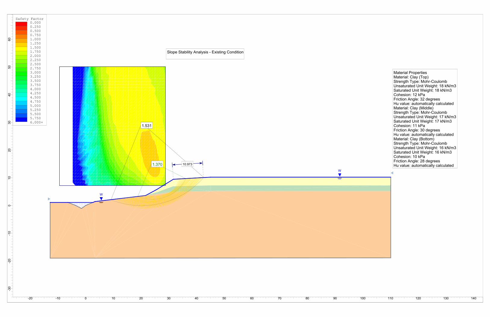
Short term analysis was performed using the constant, measured values of the clay
shear strength, while long term analysis was performed using conservative estimated
based on both the measurements taken as well as published values. An effective
cohesion of 12kPa and effective angle of friction 32 degrees were used for the clay crust
down to about 3m. The parameters were then lowered to 11kPa and 30 degrees down
to 5m and the bottom deposits were given 10kPa and 28 degrees for the same
parameters in the long term stability analysis. The unit weights chosen for the analyses
were 18kN/m3, 17kN/m3 and 16kN/m3 respectively. The slope was analyzed under full
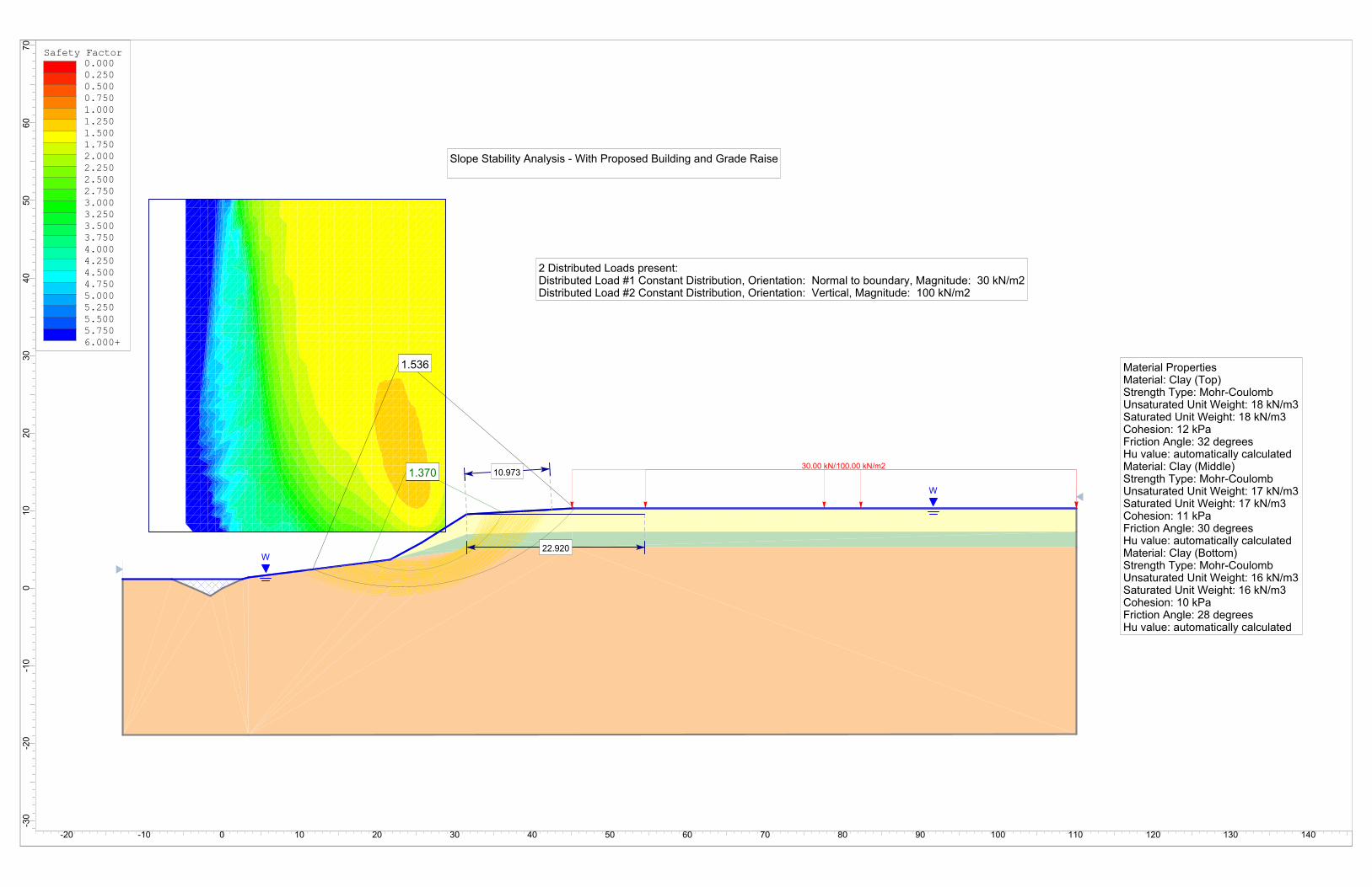
saturation. The analysis was completed for both the existing condition (pre-
development) as well as with the addition of the proposed building and 1.2m of fill
material up to the property line (post-development).
The analysis conducted on the slope section revealed the factor of safety against short
term stability is well above 1.5 but was approximately 1.3 under the long term stability
condition. A factor of safety of 1.5 or greater is generally considered to be safe for
Geotechnical Investigation LRL File: 130708Proposed New Commercial Building December 20131015 Dairy Drive, Ottawa, Ontario Page 18 of 22
LRL Associates Ltd.
development with regard to long-term stability. A factor of safety of 1.5 or greater is
obtained at 11m from the crest of the slope, which would consist of the geotechnical
setback for long term stability analysis.
Furthermore, as part of the requirements of the City of Ottawa, a Toe Erosion Allowance
of 6m and an Erosion Access Allowance of 6m must also be included in the total setback
from the crest of the slope. Consequently, the total setback required for this
development would be 23m measured from the crest of the slope.
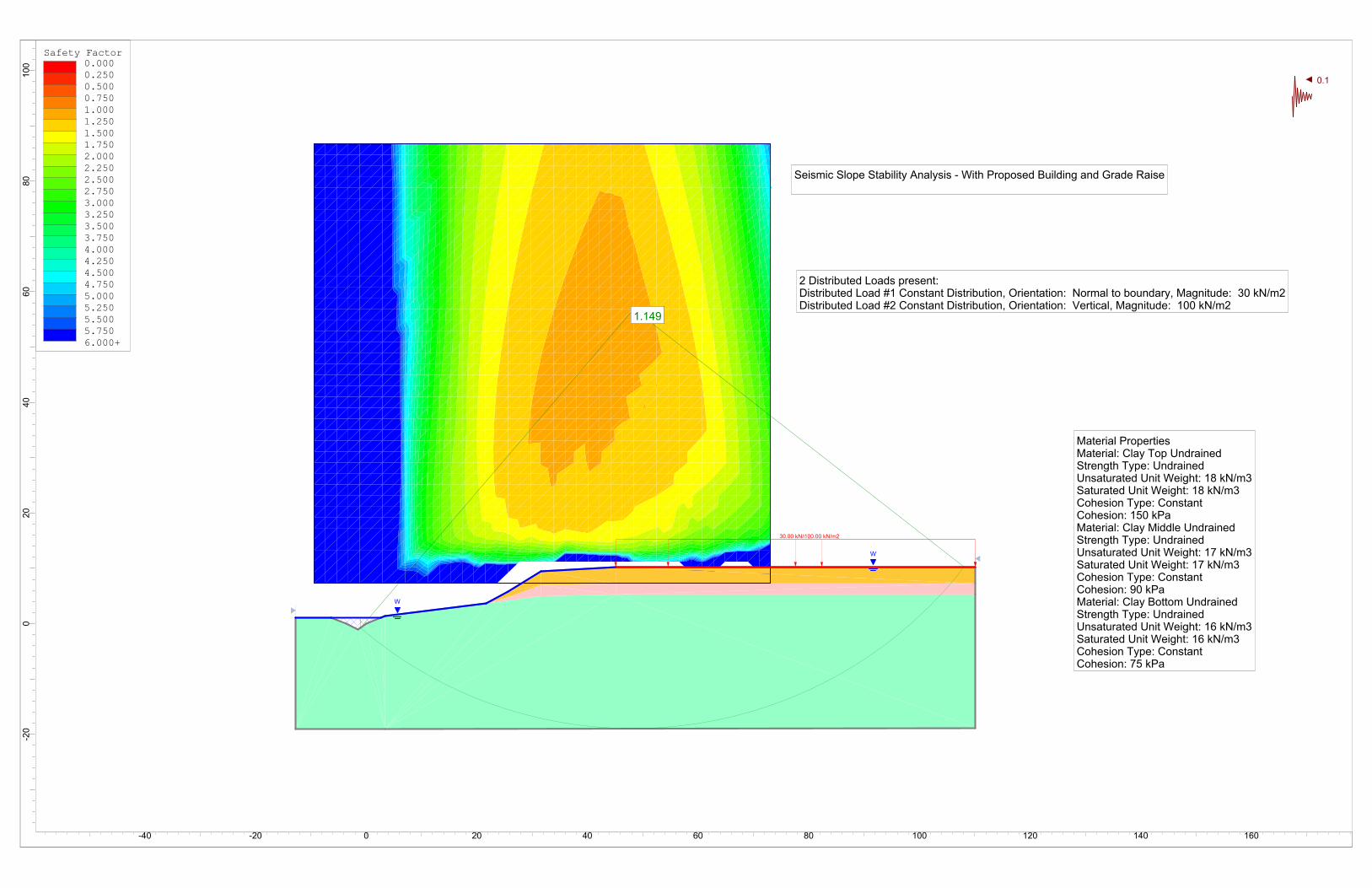
In addition to the static analysis, a seismic analysis was completed on this slope for the
proposed development. A horizontal coefficient of acceleration of 0.1 was chosen for the
analysis as given in the City of Ottawa Slope Stability Guidelines dated September 2004.
The analysis was conducted using undrained shear strengths of 150kPa, 90kPa and
75kPa for the three soil layers noted above. The factor of safety yielded by the analysis
was 1.15. A factor of safety of 1.1 is generally considered to be safe for stability during a
seismic event. As such, seismic conditions are not a concern for this development.
Considering that the slope is not a parallel with the property line and meanders with the
creek, it would be prudent to have the top of slope properly located by an Ontario Land
Surveyor in conjunction with the geotechnical engineer in order that extent of the
setback can be properly established on a site plan.
8.3 Recommendations
Based on the slope stability assessment, the following recommendations are given to
maintain the existing slope stability:
No building structures shall be located within the total setback established herein
(23m).
No fill material shall be placed within the geotechnical setbacks given, which
would create a loading condition to the existing slope.
The property owner as well as the City of Ottawa should monitor the activities of
the neighbour to the east in regard to any works completed within or near the
Geotechnical Investigation LRL File: 130708Proposed New Commercial Building December 20131015 Dairy Drive, Ottawa, Ontario Page 19 of 22
LRL Associates Ltd.
slope, which may be affect the site under investigation and the overall stability of
the slope.
Any proposed surficial drainage from the project shall be diverted away from the
slope.
9 PAVEMENT DESIGN
It is anticipated that the subgrade soils will consist mostly of native silty clay. For
predictable performance of the pavement areas, any organic, soft or deleterious
materials should be removed from the proposed pavement areas to expose native
undisturbed subgrade soil. The exposed subgrade should be inspected and approved
by geotechnical personnel and any evidently loose and unstable areas should be sub-
excavated and replaced with suitable earth borrow approved by the geotechnical
engineer. The subgrade should be shaped and crowned to promote drainage of the
roadway. Following approval of the preparation of the subgrade, the granular subbase
may be placed.
The following are the recommended pavement structures for light and heavy duty
access roads as part of this project.
For light vehicle parking areas and access lanes, the pavement should consist of:
50 millimetres of hot mix asphaltic concrete (HL3) over
150 millimetres of OPSS Granular A base over
300 millimetres of OPSS Granular B Type II subbase
For heavy duty access roads, the pavement should consist of:
40 millimetres of hot mix asphaltic concrete surface layer (HL3) over
40 millimetres of hot mix asphaltic concrete binder layer (HL8) over
150 millimetres of OPSS Granular A base over
350 millimetres of OPSS Granular B, Type II subbase
The base and sub base granular materials shall conform to OPSS Form 1010 material
specifications. The sub base material shall be free draining and not prone to capillary
Geotechnical Investigation LRL File: 130708Proposed New Commercial Building December 20131015 Dairy Drive, Ottawa, Ontario Page 20 of 22
LRL Associates Ltd.
uprising. They shall be tested and approved by a geotechnical engineer prior to delivery
to the site and shall be compacted to 100% SPMDD.
Asphaltic concrete shall conform to OPSS Form 1150 and be placed and compacted to
at least 97% of the Marshall Density. The mix and its constituents shall be reviewed,
tested and approved by a geotechnical engineer prior to delivery to the site.
9.1 Paved Areas and Subgrade Preparation
The proposed access lanes and parking areas shall be stripped of vegetation, debris
and other obvious objectionable material. Following the backfilling and satisfactory
compaction of any underground service trenches up to the subgrade level, the subgrade
shall be shaped, crowned and proof-rolled using heavy roller with any resulting soft
areas being sub-excavated down to an adequate bearing layer and replaced with
approved backfill. Any subgrade fill needed should be placed in small lifts and
compacted to 95% of SPMDD.
The preparation of the subgrade shall be scheduled and carried out in a manner so that
a protective cover of overlying granular material is placed as quickly as possible in order
to avoid unnecessary circulation by heavy equipment, except on unexcavated or
protected surfaces. Frost protection of the surface shall be implemented if works are
carried out during the winter months.
The performance of the pavement structure is highly dependent on the subsurface
groundwater conditions and maintaining the subgrade and pavement structure in a dry
condition. To intercept excess subsurface water within the pavement structure granular
materials, sub-drains with suitable outlets must be installed below the pavement area’s
subgrade if adequate overland flow drainage is not provided (i.e. ditches). The surface
of the pavement should be properly graded to direct runoff water towards suitable
drainage features. It is recommended that the lateral extent of the subbase and base
layers not be terminated vertically immediately behind the curb/edge of pavement line
but be extended beyond the curb.
Geotechnical Investigation LRL File: 130708Proposed New Commercial Building December 20131015 Dairy Drive, Ottawa, Ontario Page 21 of 22
LRL Associates Ltd.
10 INSPECTION SERVICES
The engagement of the services of the geotechnical consultant during construction is
recommended to confirm that the subsurface conditions throughout the proposed
development do not materially differ from those given in the report and that the
construction activities do not adversely affect the intent of the design.
All footing areas and any engineered fill areas for the proposed addition should be
inspected by LRL Associates Ltd. to ensure that a suitable subgrade has been reached
and properly prepared. The placing and compaction of any granular materials beneath
the foundations and slab-on-grade should be inspected to ensure that the materials used
conform to the grading and compaction specifications.
The subgrade for the pavement areas, watermain and sewers must be inspected and
approved by geotechnical personnel. In-situ density testing should be carried out on the
pavement granular materials and pipe bedding and backfill to ensure the materials meet
the specifications from a compaction point of view.
If footings are to be constructed during winter months, the footing subgrade must be
protected from freezing temperatures using suitable construction techniques.
11 REPORT CONDITIONS AND LIMITATIONS
It is stressed that the information presented in this report is provided for the guidance of
the designers and is intended for this project only. The use of this report as a
construction document or its use by a third party other than the client specifically listed in
the report is neither intended nor authorized by LRL Associates Ltd. Contractors bidding
on or undertaking the works should examine the factual results of the investigation,
satisfy themselves as to the adequacy of the information for construction, and make their
own interpretation of the factual data as it affects their construction techniques,
schedule, safety and equipment capabilities.
The professional services for this project include only the geotechnical aspects of the
subsurface conditions at this site. The presence or implications of possible surface
Geotechnical Investigation LRL File: 130708Proposed New Commercial Building December 2013Ottawa, Ontario Appendix A
LRL Associates Ltd.
APPENDIX A
TEST PIT LOCATION PLAN
(59
.80)
(58
.58)
(59
.85)(6
1.42)
(62
.55)
(62
.24)
(61
.61)
(60
.09)
TOP
OF SLO
PE
ED
GE
OF C
REEK
Prop
erty Line
Legen
d
(99.99)Test Pit Lo
cation
An
dG
rou
nd
Surface Elevatio
n
Ben
chm
ark(San
itary Man
ho
le)
Ed
ge o
f Top
soil Sto
ckpile
DATE
PR
OJE
CT N
O.
130708
NO
VEM
BER
2013
DES
IGN
ED
BY:A
PPR
OVE
D BY:
DR
AW
N B
Y:
CLIEN
T
M.L.
M.E.
DR
YTE
CH
INTER
NA
TION
AL INC
.
DR
AW
ING
TITLE
PR
OJEC
T
GE
OTE
CH
NIC
AL IN
VESTIGATIO
N1015 D
AIR
Y DR
IVEO
TTAWA, O
NTAR
IO
LASSOCIATES
ASSOCIÉS
ENGINEERSINGÉNIEURS
L1-2884 Cham
berland StreetRockland, O
ntarioK4K 1M
6
(613)446-7777
(877)632-5664
(613)446-1427
Tel:
Website: w
ww
.LRL.caFax:
BY
No.
RE
VIS
ION
SD
ATE
TES
T PIT LO
CATIO
N PLAN
Geotechnical Investigation LRL File: 130708Proposed New Commercial Building December 20131015 Dairy Drive, Ottawa, Ontario Appendix B
LRL Associates Ltd.
APPENDIX B
TEST PIT LOGS
Test Pit Log:
Date:
Project No.:
Client:
Project:
Location:
Field Personnel:
Excavation Method: Excavation Contractor:
Easting: Northing:
Site Datum:
Groundsurface Elevation: Top of Riser Elev.:
Excavation Width: Excavation Length:
Page: 1 of 1
SUBSURFACE PROFILE SAMPLE DATA
Dep
th
0 0ft m
1
1
2
2
3
3
4
4
5
5
6
7
8
9
10
11
12
13
14
15
16
Soil Description
Elev
./Dep
th(m
)
Sam
ple
Num
ber
Water Level(Standpipe or
Open Excavation)
NOTES:
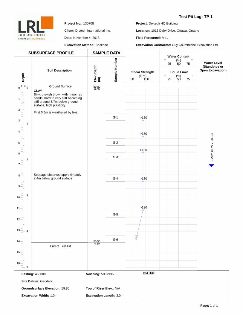
TP-1
November 4, 2013
130708
Drytech International Inc.
Drytech HQ Building
1015 Dairy Drive, Ottawa, Ontario
M.L.
Backhoe Guy Courchesne Excavation Ltd.
Ground SurfaceCLAYSilty, greyish brown with minor redbands, hard to very stiff becomingstiff around 3.7m below groundsurface, high plasticity.
First 0.6m is weathered by frost.
End of Test Pit
Seepage observed approximately2.4m below ground surface
59.800.00
55.504.30
S-1
S-2
S-3
S-4
S-5
S-6
50 150(kPa)
Shear Strength
>130
>130
>130
>130
>130
80
25 50 75(%)
Liquid Limit
25 50 75(%)
Water Content
2.20
m (N
ov 7
,201
3)
463000 5037936
Geodetic
59.80 N/A
1.0m 3.0m
Test Pit Log:
Date:
Project No.:
Client:
Project:
Location:
Field Personnel:
Excavation Method: Excavation Contractor:
Easting: Northing:
Site Datum:
Groundsurface Elevation: Top of Riser Elev.:
Excavation Width: Excavation Length:
Page: 1 of 1
SUBSURFACE PROFILE SAMPLE DATA
Dep
th
0 0ft m
1
1
2
2
3
3
4
4
5
5
6
7
8
9
10
11
12
13
14
15
16
Soil Description
Elev
./Dep
th(m
)
Sam
ple
Num
ber
Water Level(Standpipe or
Open Excavation)
NOTES:
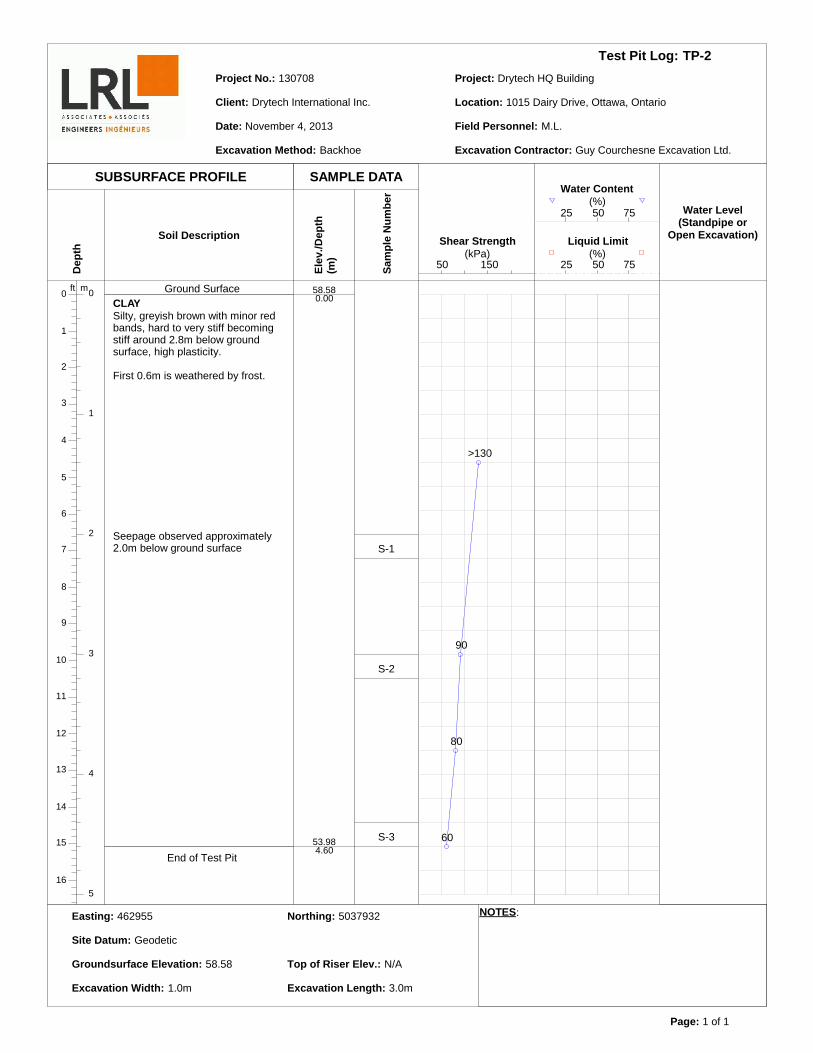
TP-2
November 4, 2013
130708
Drytech International Inc.
Drytech HQ Building
1015 Dairy Drive, Ottawa, Ontario
M.L.
Backhoe Guy Courchesne Excavation Ltd.
Ground SurfaceCLAYSilty, greyish brown with minor redbands, hard to very stiff becomingstiff around 2.8m below groundsurface, high plasticity.
First 0.6m is weathered by frost.
End of Test Pit
Seepage observed approximately2.0m below ground surface
58.580.00
53.984.60
S-1
S-2
S-3
50 150(kPa)
Shear Strength
>130
90
80
60
25 50 75(%)
Liquid Limit
25 50 75(%)
Water Content
462955 5037932
Geodetic
58.58 N/A
1.0m 3.0m
Test Pit Log:
Date:
Project No.:
Client:
Project:
Location:
Field Personnel:
Excavation Method: Excavation Contractor:
Easting: Northing:
Site Datum:
Groundsurface Elevation: Top of Riser Elev.:
Excavation Width: Excavation Length:
Page: 1 of 1
SUBSURFACE PROFILE SAMPLE DATA
Dep
th
0 0ft m
1
1
2
2
3
3
4
4
5
5
6
7
8
9
10
11
12
13
14
15
16
Soil Description
Elev
./Dep
th(m
)
Sam
ple
Num
ber
Water Level(Standpipe or
Open Excavation)
NOTES:
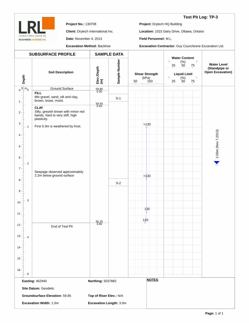
TP-3
November 4, 2013
130708
Drytech International Inc.
Drytech HQ Building
1015 Dairy Drive, Ottawa, Ontario
M.L.
Backhoe Guy Courchesne Excavation Ltd.
Ground SurfaceFILLMix gravel, sand, silt and clay,brown, loose, moist.
CLAYSilty, greyish brown with minor redbands, hard to very stiff, highplasticity.
First 0.3m is weathered by frost.
End of Test Pit
Seepage observed approximately2.2m below ground surface
59.850.00
59.450.40
56.253.60
S-1
S-2
50 150(kPa)
Shear Strength
>130
>130
130
120
25 50 75(%)
Liquid Limit
25 50 75(%)
Water Content
2.00
m (N
ov 7
,201
3)
462940 5037882
Geodetic
59.85 N/A
1.0m 3.0m

Test Pit Log:
Date:
Project No.:
Client:
Project:
Location:
Field Personnel:
Excavation Method: Excavation Contractor:
Easting: Northing:
Site Datum:
Groundsurface Elevation: Top of Riser Elev.:
Excavation Width: Excavation Length:
Page: 1 of 1
SUBSURFACE PROFILE SAMPLE DATA
Dep
th
0 0ft m
1
1
2
2
3
3
4
4
5
5
6
7
8
9
10
11
12
13
14
15
16
Soil Description
Elev
./Dep
th(m
)
Sam
ple
Num
ber
Water Level(Standpipe or
Open Excavation)
NOTES:
TP-4
November 4, 2013
130708
Drytech International Inc.
Drytech HQ Building
1015 Dairy Drive, Ottawa, Ontario
M.L.
Backhoe Guy Courchesne Excavation Ltd.
Ground SurfaceCLAYSilty, greyish brown with minor redbands, hard to very stiff becomingstiff around 3.7m below groundsurface, high plasticity.
First 0.6m is weathered by frost.
End of Test Pit
Seepage observed approximately2.2m below ground surface
61.610.00
57.014.60
S-1
S-2
S-3
S-4
50 150(kPa)
Shear Strength
>130
>130
110
70
25 50 75(%)
Liquid Limit
25 50 75(%)
Water Content
463047 5037848
Geodetic
61.61 N/A
1.0m 3.0m
Test Pit Log:
Date:
Project No.:
Client:
Project:
Location:
Field Personnel:
Excavation Method: Excavation Contractor:
Easting: Northing:
Site Datum:
Groundsurface Elevation: Top of Riser Elev.:
Excavation Width: Excavation Length:
Page: 1 of 1
SUBSURFACE PROFILE SAMPLE DATA
Dep
th
0 0ft m
1
1
2
2
3
3
4
4
5
5
6
7
8
9
10
11
12
13
14
15
16
Soil Description
Elev
./Dep
th(m
)
Sam
ple
Num
ber
Water Level(Standpipe or
Open Excavation)
NOTES:
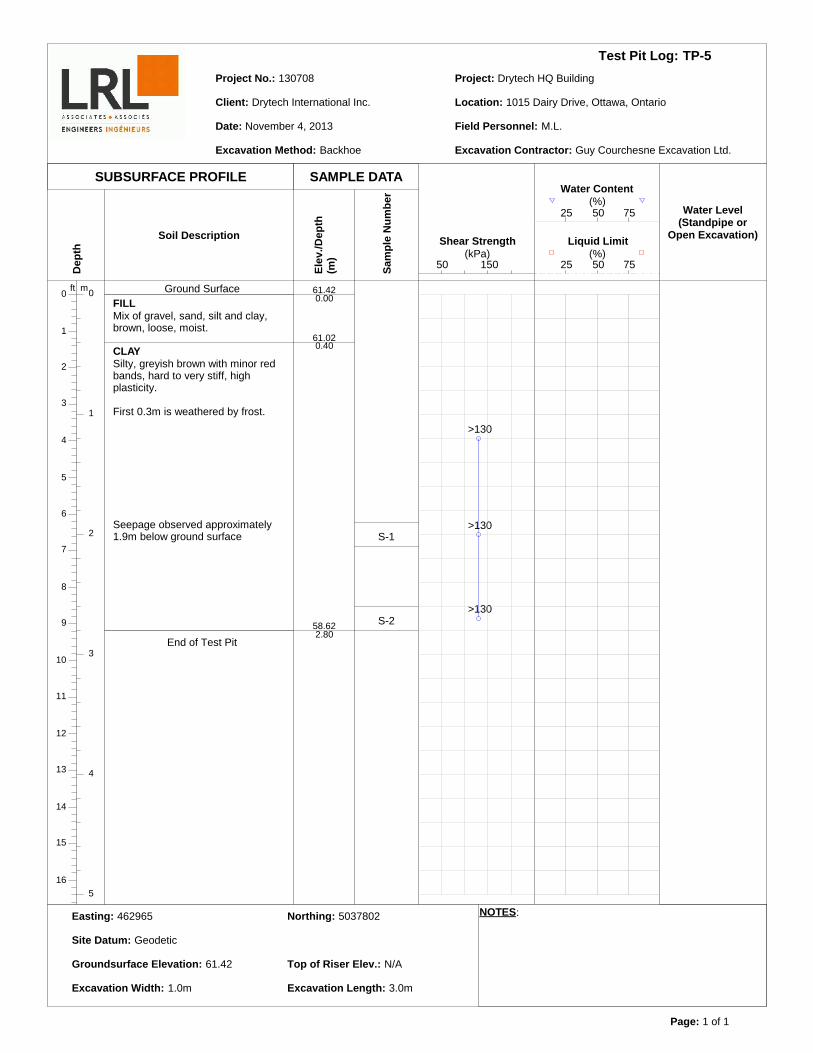
TP-5
November 4, 2013
130708
Drytech International Inc.
Drytech HQ Building
1015 Dairy Drive, Ottawa, Ontario
M.L.
Backhoe Guy Courchesne Excavation Ltd.
Ground SurfaceFILLMix of gravel, sand, silt and clay,brown, loose, moist.
CLAYSilty, greyish brown with minor redbands, hard to very stiff, highplasticity.
First 0.3m is weathered by frost.
End of Test Pit
Seepage observed approximately1.9m below ground surface
61.420.00
61.020.40
58.622.80
S-1
S-2
50 150(kPa)
Shear Strength
>130
>130
>130
25 50 75(%)
Liquid Limit
25 50 75(%)
Water Content
462965 5037802
Geodetic
61.42 N/A
1.0m 3.0m

Test Pit Log:
Date:
Project No.:
Client:
Project:
Location:
Field Personnel:
Excavation Method: Excavation Contractor:
Easting: Northing:
Site Datum:
Groundsurface Elevation: Top of Riser Elev.:
Excavation Width: Excavation Length:
Page: 1 of 1
SUBSURFACE PROFILE SAMPLE DATA
Dep
th
0 0ft m
1
1
2
2
3
3
4
4
5
5
6
7
8
9
10
11
12
13
14
15
16
Soil Description
Elev
./Dep
th(m
)
Sam
ple
Num
ber
Water Level(Standpipe or
Open Excavation)
NOTES:
TP-6
November 4, 2013
130708
Drytech International Inc.
Drytech HQ Building
1015 Dairy Drive, Ottawa, Ontario
M.L.
Backhoe Guy Courchesne Excavation Ltd.
Ground SurfaceCLAYSilty, greyish brown with minor redbands, hard to very stiff becomingstiff around 3.8m below groundsurface, high plasticity.
First 0.6m is weathered by frost.
End of Test Pit
Seepage observed approximately2.0m below ground surface
62.240.00
58.144.10
S-1
S-2
S-3
50 150(kPa)
Shear Strength
>130
>130
120
90
25 50 75(%)
Liquid Limit
25 50 75(%)
Water Content
1.80
m (N
ov 7
,201
3)
463032 5037795
Geodetic
62.24 N/A
1.0m 3.3m
Test Pit Log:
Date:
Project No.:
Client:
Project:
Location:
Field Personnel:
Excavation Method: Excavation Contractor:
Easting: Northing:
Site Datum:
Groundsurface Elevation: Top of Riser Elev.:
Excavation Width: Excavation Length:
Page: 1 of 1
SUBSURFACE PROFILE SAMPLE DATA
Dep
th
0 0ft m
1
1
2
2
3
3
4
4
5
5
6
7
8
9
10
11
12
13
14
15
16
Soil Description
Elev
./Dep
th(m
)
Sam
ple
Num
ber
Water Level(Standpipe or
Open Excavation)
NOTES:
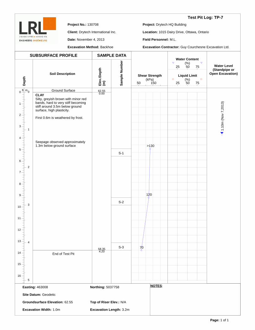
TP-7
November 4, 2013
130708
Drytech International Inc.
Drytech HQ Building
1015 Dairy Drive, Ottawa, Ontario
M.L.
Backhoe Guy Courchesne Excavation Ltd.
Ground SurfaceCLAYSilty, greyish brown with minor redbands, hard to very stiff becomingstiff around 3.5m below groundsurface, high plasticity.
First 0.6m is weathered by frost.
End of Test Pit
Seepage observed approximately1.3m below ground surface
62.550.00
58.354.20
S-1
S-2
S-3
50 150(kPa)
Shear Strength
>130
120
70
25 50 75(%)
Liquid Limit
25 50 75(%)
Water Content
1.10
m (N
ov 7
,201
3)
463008 5037758
Geodetic
62.55 N/A
1.0m 3.2m
Test Pit Log:
Date:
Project No.:
Client:
Project:
Location:
Field Personnel:
Excavation Method: Excavation Contractor:
Easting: Northing:
Site Datum:
Groundsurface Elevation: Top of Riser Elev.:
Excavation Width: Excavation Length:
Page: 1 of 1
SUBSURFACE PROFILE SAMPLE DATA
Dep
th
0 0ft m
1
1
2
2
3
3
4
4
5
5
6
7
8
9
10
11
12
13
14
15
16
Soil Description
Elev
./Dep
th(m
)
Sam
ple
Num
ber
Water Level(Standpipe or
Open Excavation)
NOTES:
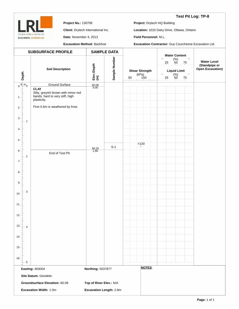
TP-8
November 4, 2013
130708
Drytech International Inc.
Drytech HQ Building
1015 Dairy Drive, Ottawa, Ontario
M.L.
Backhoe Guy Courchesne Excavation Ltd.
Ground SurfaceCLAYSilty, greyish brown with minor redbands, hard to very stiff, highplasticity.
First 0.6m is weathered by frost.
End of Test Pit
60.090.00
58.291.80
S-1
50 150(kPa)
Shear Strength
>130
25 50 75(%)
Liquid Limit
25 50 75(%)
Water Content
463004 5037877
Geodetic
60.09 N/A
1.0m 2.8m
Geotechnical Investigation LRL File: 130708Proposed New Commercial Building December 20131015 Dairy Drive, Ottawa, Ontario Appendix C
LRL Associates Ltd.
APPENDIX C
LABORATORY TEST REPORTS – PHYSICAL TESTS
Geotechnical Investigation LRL File: 130708Proposed New Commercial Building December 20131015 Dairy Drive, Ottawa, Ontario Appendix D
LRL Associates Ltd.
APPENDIX D
LABORATORY CERTIFICATE OF ANALYSIS – CHEMICAL TESTS
Order Date: 5-Nov-2013 Report Date: 11-Nov-2013
Fax: (613) 446-1427Phone: (613) 446-7777
Client PO:
This Certificate of Analysis contains analytical data applicable to the following samples as submitted:
Custody: 13649
Attn: Maxime LerouxRockland, ON K4K1M62884 Chamberland St.
Certificate of Analysis
Paracel ID Client ID
LRL Associates Ltd.
Order #: 1345103
Project: 130708
1345103-01 TP5-S2 (d=2.6m-2.8m)1345103-02 TP7-S1 (d=1.5m-1.7m)1345103-03 TP1-S2 (d=1.4m-1.6m)
Approved By:Mark Foto, M.Sc. For Dale Robertson, BScLaboratory Director
Page 1 of 7
Any use of these results implies your agreement that our total liabilty in connection with this work, however arising shall be limited to the amount paid by you for this work, and that our employees or agents shall not under circumstances be liable to you in connection with this work
Certificate of AnalysisClient:
Report Date: 11-Nov-2013Order Date:5-Nov-2013
Client PO: Project Description: 130708LRL Associates Ltd.
Order #: 1345103
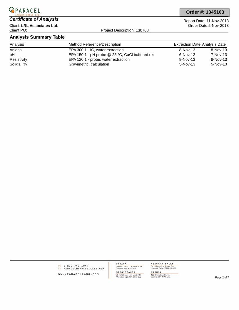
Analysis Summary Table
Analysis Method Reference/Description Extraction Date Analysis Date
EPA 300.1 - IC, water extraction 8-Nov-13 8-Nov-13AnionsEPA 150.1 - pH probe @ 25 °C, CaCl buffered ext. 6-Nov-13 7-Nov-13pHEPA 120.1 - probe, water extraction 8-Nov-13 8-Nov-13ResistivityGravimetric, calculation 5-Nov-13 5-Nov-13Solids, %
Page 2 of 7
Certificate of AnalysisClient:
Report Date: 11-Nov-2013Order Date:5-Nov-2013
Client PO: Project Description: 130708LRL Associates Ltd.
Order #: 1345103
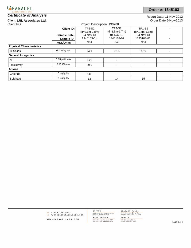
Client ID: TP5-S2 (d=2.6m-2.8m)
TP7-S1 (d=1.5m-1.7m)
TP1-S2 (d=1.4m-1.6m)
-
Sample Date: -04-Nov-1304-Nov-1304-Nov-131345103-01 1345103-02 1345103-03 -Sample ID:
MDL/Units Soil Soil Soil -
Physical Characteristics
% Solids -77.970.874.10.1 % by Wt.
General Inorganics
pH ---7.290.05 pH Units
Resistivity ---29.90.10 Ohm.m
Anions
Chloride ---1115 ug/g dry
Sulphate -1514135 ug/g dry
Page 3 of 7
Certificate of AnalysisClient:
Report Date: 11-Nov-2013Order Date:5-Nov-2013
Client PO: Project Description: 130708LRL Associates Ltd.
Order #: 1345103
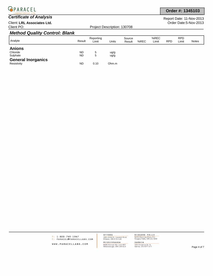
Method Quality Control: Blank
Analyte ResultReporting
Limit UnitsSourceResult %REC
%RECLimit RPD
RPDLimit Notes
AnionsChloride ND 5 ug/gSulphate ND 5 ug/g
General InorganicsResistivity ND 0.10 Ohm.m
Page 4 of 7
Certificate of AnalysisClient:
Report Date: 11-Nov-2013Order Date:5-Nov-2013
Client PO: Project Description: 130708LRL Associates Ltd.
Order #: 1345103
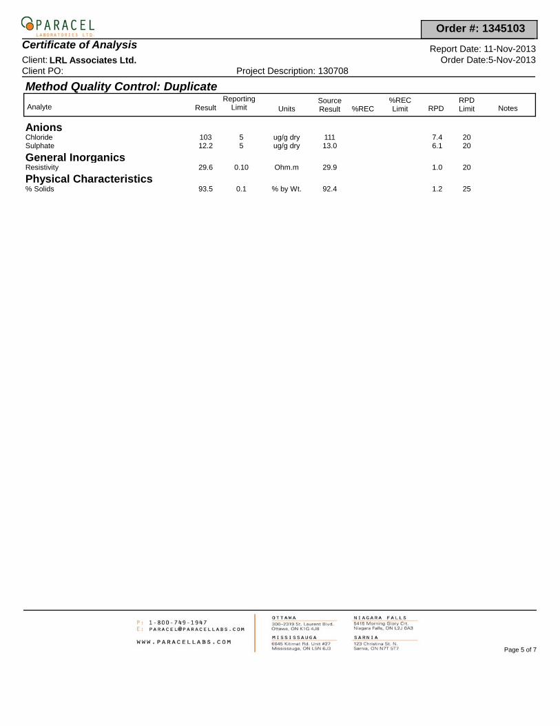
Method Quality Control: Duplicate
Analyte ResultReporting
Limit UnitsSourceResult %REC
%RECLimit RPD
RPDLimit Notes
AnionsChloride 103 5 ug/g dry 111 207.4Sulphate 12.2 5 ug/g dry 13.0 206.1
General InorganicsResistivity 29.6 0.10 Ohm.m 29.9 201.0
Physical Characteristics% Solids 93.5 0.1 % by Wt. 92.4 251.2
Page 5 of 7
Certificate of AnalysisClient:
Report Date: 11-Nov-2013Order Date:5-Nov-2013
Client PO: Project Description: 130708LRL Associates Ltd.
Order #: 1345103
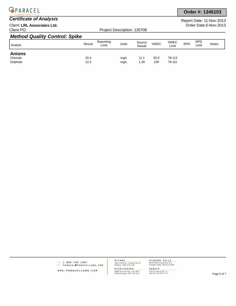
Method Quality Control: Spike
Analyte ResultReporting
Limit Units SourceResult
%REC %RECLimit
RPDRPDLimit Notes
AnionsChloride 20.4 11.1 93.5 78-113mg/LSulphate 12.2 1.30 109 78-111mg/L
Page 6 of 7
Certificate of AnalysisClient:
Report Date: 11-Nov-2013Order Date:5-Nov-2013
Client PO: Project Description: 130708LRL Associates Ltd.
Order #: 1345103
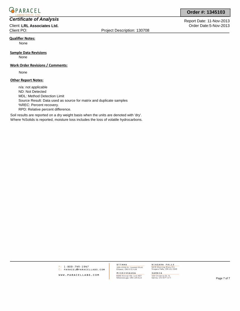
Qualifier Notes :None
Sample Data RevisionsNone
Work Order Revisions / Comments :
None
Other Report Notes :
MDL: Method Detection Limit
n/a: not applicable
Source Result: Data used as source for matrix and duplicate samples%REC: Percent recovery.RPD: Relative percent difference.
ND: Not Detected
Soil results are reported on a dry weight basis when the units are denoted with 'dry'.Where %Solids is reported, moisture loss includes the loss of volatile hydrocarbons.
Page 7 of 7
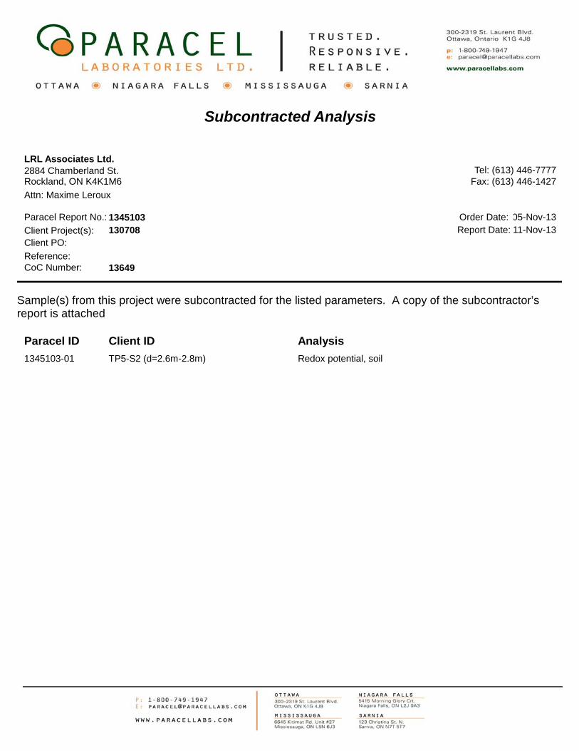
Subcontracted Analysis
2884 Chamberland St.Rockland, ON K4K1M6
Attn: Maxime Leroux
Tel: (613) 446-7777Fax: (613) 446-1427
Paracel Report No.: 1345103Client Project(s): 130708Client PO:
CoC Number: 13649Reference:
Order Date: 05-Nov-13Report Date: 11-Nov-13
Sample(s) from this project were subcontracted for the listed parameters. A copy of the subcontractor’s report is attached
Paracel ID AnalysisClient ID
LRL Associates Ltd.
1345103-01 Redox potential, soilTP5-S2 (d=2.6m-2.8m)
[This report shall not be reproduced except in full without the written authority of the Laboratory.]
06-NOV-13
Lab Work Order #: L1388492
Date Received:PARACEL LABORATORIES LTD
300-2319 St. Laurent Blvd.Ottawa ON K1G 4J8
ATTN: Dale RobertsonFINAL 08-NOV-13 09:43 (MT)Report Date:
Version:
Certificate of Analysis
ALS CANADA LTD Part of the ALS Group A Campbell Brothers Limited Company
____________________________________________
Bryan MarkAccount Manager
ADDRESS: 190 Colonnade Road, Unit 7, Ottawa, ON K2E 7J5 Canada | Phone: +1 613 225 8279 | Fax: +1 613 225 2801
Client Phone: 613-731-9577
1345103Job Reference: NOT SUBMITTEDProject P.O. #:
C of C Numbers: Legal Site Desc:
ALS ENVIRONMENTAL ANALYTICAL REPORT
L1388492 CONTD....2PAGE
Result D.L. Units Extracted AnalyzedSample Details/Parameters
of1345103
Qualifier* Batch
* Refer to Referenced Information for Qualifiers (if any) and Methodology.
Version: FINAL 3
L1388492-1 TP5-S2 (D=2.6M-2.8M)CLIENT on 04-NOV-13Sampled By:
SOIL
Redox Potential mV 07-NOV-13 07-NOV-13291 -1000
Matrix:
R2735949
REDOX-POTENTIAL-WT
Reference Information
Redox Potential
L1388492 CONTD....
3PAGE of
1345103
ALS Test Code Test Description
Soil APHA 2580
Method Reference**
** ALS test methods may incorporate modifications from specified reference methods to improve performance.
Matrix
The last two letters of the above test code(s) indicate the laboratory that performed analytical analysis for that test. Refer to the list below:
Laboratory Definition Code Laboratory Location
WT ALS ENVIRONMENTAL - WATERLOO, ONTARIO, CANADA
Test Method References:
Chain of Custody Numbers:
GLOSSARY OF REPORT TERMSSurrogates are compounds that are similar in behaviour to target analyte(s), but that do not normally occur in environmental samples. For applicable tests, surrogates are added to samples prior to analysis as a check on recovery. In reports that display the D.L. column, laboratory objectives for surrogates are listed there.mg/kg - milligrams per kilogram based on dry weight of samplemg/kg wwt - milligrams per kilogram based on wet weight of samplemg/kg lwt - milligrams per kilogram based on lipid-adjusted weight mg/L - unit of concentration based on volume, parts per million.< - Less than.D.L. - The reporting limit.N/A - Result not available. Refer to qualifier code and definition for explanation.
Test results reported relate only to the samples as received by the laboratory.UNLESS OTHERWISE STATED, ALL SAMPLES WERE RECEIVED IN ACCEPTABLE CONDITION.Analytical results in unsigned test reports with the DRAFT watermark are subject to change, pending final QC review.
Version: FINAL 3
Geotechnical Investigation LRL File: 130708Proposed New Commercial Building December 20131015 Dairy Drive, Ottawa, Ontario Appendix E
LRL Associates Ltd.
APPENDIX E
SLOPE STABILITY ANALYSIS RESULTS
1.370
1.531
1.370
W
W
1.370
1.531
1.370
Slope Stability Analysis - Existing Condition
10.973
Material PropertiesMaterial: Clay (Top)Strength Type: Mohr-CoulombUnsaturated Unit Weight: 18 kN/m3Saturated Unit Weight: 18 kN/m3Cohesion: 12 kPaFriction Angle: 32 degreesHu value: automatically calculatedMaterial: Clay (Middle)Strength Type: Mohr-CoulombUnsaturated Unit Weight: 17 kN/m3Saturated Unit Weight: 17 kN/m3Cohesion: 11 kPaFriction Angle: 30 degreesHu value: automatically calculatedMaterial: Clay (Bottom)Strength Type: Mohr-CoulombUnsaturated Unit Weight: 16 kN/m3Saturated Unit Weight: 16 kN/m3Cohesion: 10 kPaFriction Angle: 28 degreesHu value: automatically calculated
Safety Factor0.0000.2500.5000.7501.0001.2501.5001.7502.0002.2502.5002.7503.0003.2503.5003.7504.0004.2504.5004.7505.0005.2505.5005.7506.000+
6050
4030
2010
0-1
0-2
0-3
0
-20 -10 0 10 20 30 40 50 60 70 80 90 100 110 120 130 140
1.370
1.536
1.370
W
W
30.00 kN/m2100.00 kN/m21.370
1.536
1.370
Slope Stability Analysis - With Proposed Building and Grade Raise
10.973
Material PropertiesMaterial: Clay (Top)Strength Type: Mohr-CoulombUnsaturated Unit Weight: 18 kN/m3Saturated Unit Weight: 18 kN/m3Cohesion: 12 kPaFriction Angle: 32 degreesHu value: automatically calculatedMaterial: Clay (Middle)Strength Type: Mohr-CoulombUnsaturated Unit Weight: 17 kN/m3Saturated Unit Weight: 17 kN/m3Cohesion: 11 kPaFriction Angle: 30 degreesHu value: automatically calculatedMaterial: Clay (Bottom)Strength Type: Mohr-CoulombUnsaturated Unit Weight: 16 kN/m3Saturated Unit Weight: 16 kN/m3Cohesion: 10 kPaFriction Angle: 28 degreesHu value: automatically calculated
22.920
2 Distributed Loads present:Distributed Load #1 Constant Distribution, Orientation: Normal to boundary, Magnitude: 30 kN/m2Distributed Load #2 Constant Distribution, Orientation: Vertical, Magnitude: 100 kN/m2
Safety Factor0.0000.2500.5000.7501.0001.2501.5001.7502.0002.2502.5002.7503.0003.2503.5003.7504.0004.2504.5004.7505.0005.2505.5005.7506.000+
7060
5040
3020
100
-10
-20
-30
-20 -10 0 10 20 30 40 50 60 70 80 90 100 110 120 130 140
1.1491.149
W
W
30.00 kN/m2100.00 kN/m2
1.1491.149
Seismic Slope Stability Analysis - With Proposed Building and Grade Raise
2 Distributed Loads present:Distributed Load #1 Constant Distribution, Orientation: Normal to boundary, Magnitude: 30 kN/m2Distributed Load #2 Constant Distribution, Orientation: Vertical, Magnitude: 100 kN/m2
Material PropertiesMaterial: Clay Top UndrainedStrength Type: UndrainedUnsaturated Unit Weight: 18 kN/m3Saturated Unit Weight: 18 kN/m3Cohesion Type: ConstantCohesion: 150 kPaMaterial: Clay Middle UndrainedStrength Type: UndrainedUnsaturated Unit Weight: 17 kN/m3Saturated Unit Weight: 17 kN/m3Cohesion Type: ConstantCohesion: 90 kPaMaterial: Clay Bottom UndrainedStrength Type: UndrainedUnsaturated Unit Weight: 16 kN/m3Saturated Unit Weight: 16 kN/m3Cohesion Type: ConstantCohesion: 75 kPa
Safety Factor0.0000.2500.5000.7501.0001.2501.5001.7502.0002.2502.5002.7503.0003.2503.5003.7504.0004.2504.5004.7505.0005.2505.5005.7506.000+
100
8060
4020
0-2
0
-40 -20 0 20 40 60 80 100 120 140 160
0.1

Geotechnical Investigation LRL File: 130708Proposed New Commercial Building December 20131015 Dairy Drive, Ottawa, Ontario Appendix F
LRL Associates Ltd.
APPENDIX F
SYMBOLS AND TERMS USED IN TEST PIT LOGS
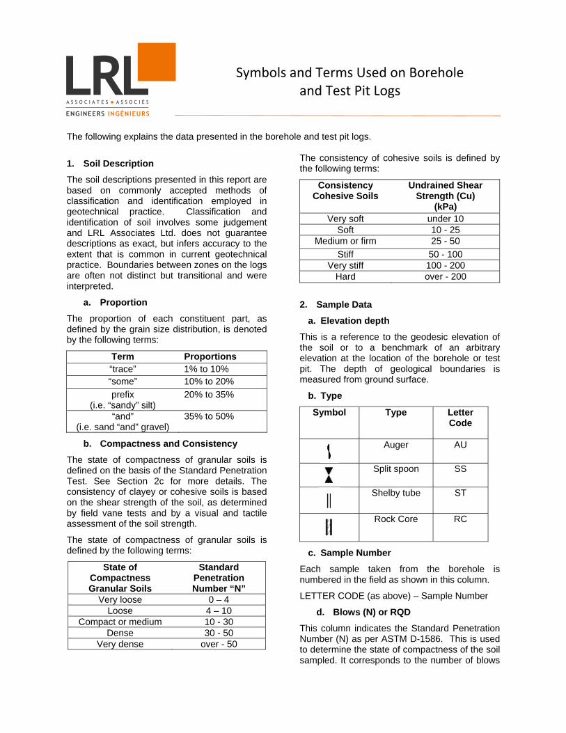
Symbols and Terms Used on Borehole and Test Pit Logs
The following explains the data presented in the borehole and test pit logs.
1. Soil Description
The soil descriptions presented in this report are based on commonly accepted methods of classification and identification employed in geotechnical practice. Classification and identification of soil involves some judgement and LRL Associates Ltd. does not guarantee descriptions as exact, but infers accuracy to the extent that is common in current geotechnical practice. Boundaries between zones on the logs are often not distinct but transitional and were interpreted.
a. Proportion
The proportion of each constituent part, as defined by the grain size distribution, is denoted by the following terms:
Term Proportions “trace” 1% to 10% “some” 10% to 20% prefix
(i.e. “sandy” silt) 20% to 35%
“and” (i.e. sand “and” gravel)
35% to 50%
b. Compactness and Consistency
The state of compactness of granular soils is defined on the basis of the Standard Penetration Test. See Section 2c for more details. The consistency of clayey or cohesive soils is based on the shear strength of the soil, as determined by field vane tests and by a visual and tactile assessment of the soil strength.
The state of compactness of granular soils is defined by the following terms:
State of Compactness Granular Soils
Standard Penetration Number “N”
Very loose 0 – 4 Loose 4 – 10
Compact or medium 10 - 30 Dense 30 - 50
Very dense over - 50
The consistency of cohesive soils is defined by the following terms:
Consistency Cohesive Soils
Undrained Shear Strength (Cu)
(kPa) Very soft under 10
Soft 10 - 25 Medium or firm 25 - 50
Stiff 50 - 100 Very stiff 100 - 200
Hard over - 200
2. Sample Data
a. Elevation depth
This is a reference to the geodesic elevation of the soil or to a benchmark of an arbitrary elevation at the location of the borehole or test pit. The depth of geological boundaries is measured from ground surface.
b. Type
Symbol Type Letter Code
Auger AU
Split spoon SS
Shelby tube ST
Rock Core RC
c. Sample Number
Each sample taken from the borehole is numbered in the field as shown in this column.
LETTER CODE (as above) – Sample Number
d. Blows (N) or RQD
This column indicates the Standard Penetration Number (N) as per ASTM D-1586. This is used to determine the state of compactness of the soil sampled. It corresponds to the number of blows
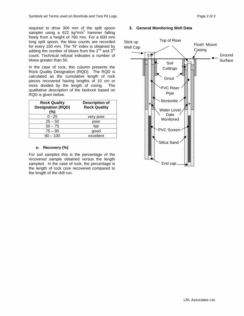
Symbols ad Terms used on Borehole and Test Pit Logs Page 2 of 2
LRL Associates Ltd.
required to drive 300 mm of the split spoon sampler using a 622 kg*m/s2 hammer falling freely from a height of 760 mm. For a 600 mm long split spoon, the blow counts are recorded for every 150 mm. The “N” index is obtained by adding the number of blows from the 2nd and 3rd count. Technical refusal indicates a number of blows greater than 50.
In the case of rock, this column presents the Rock Quality Designation (RQD). The RQD is calculated as the cumulative length of rock pieces recovered having lengths of 10 cm or more divided by the length of coring. The qualitative description of the bedrock based on RQD is given below.
e. Recovery (%)
For soil samples this is the percentage of the recovered sample obtained versus the length sampled. In the case of rock, the percentage is the length of rock core recovered compared to the length of the drill run.
3. General Monitoring Well Data
Rock Quality Designation (RQD)
(%)
Description of Rock Quality
0 –25 very poor 25 – 50 poor 50 – 75 fair 75 – 90 good
90 – 100 excellent
Water Level Date
Monitored
PVC Riser Pipe
PVC Screen
Flush Mount Casing
Silica Sand
Bentonite
End cap
Top of Riser Stick up Well Cap
Grout
Soil Cuttings
Ground Surface