Embed Size (px)
Citation preview
220 - 18 Gostick Place P: 604-990-0546 North Vancouver, BC F: 604-990-0583 Canada V7M 3G3 www.horizoneng.ca
Consulting Geotechnical Engineers ©Horizon Engineering Inc.
GEOTECHNICAL INVESTIGATION REPORT
Proposed Housing for Women / Mixed-Use Development 546 West 13th Avenue
Vancouver, BC
Prepared for: Soroptimist International of Vancouver
546 West 13th Avenue Vancouver, BC
Our File: 120-4733
October 22, 2020
Proposed Housing for Women / Mixed-Use Development Our File: 120-4733 546 West 13th Avenue, Vancouver, BC October 22, 2020 Geotechnical Investigation Report Page ii
Consulting Geotechnical Engineers ©Horizon Engineering Inc.
TABLE OF CONTENTS 1.0 INTRODUCTION ................................................................................................................ 1 2.0 SITE DESCRIPTION .......................................................................................................... 1 3.0 BACKGROUND INFORMATION ...................................................................................... 1
Reference Documents .................................................................................................... 1 Proposed Development .................................................................................................. 2 Surficial Geology ............................................................................................................ 2 Seismic Data .................................................................................................................. 2
4.0 SUBSURFACE INVESTIGATION ..................................................................................... 3 Soil Conditions ................................................................................................................ 3
4.1.1 Fill / Topsoil ............................................................................................................. 3 4.1.2 Reddish-Brown Sand .............................................................................................. 3 4.1.3 Silty Sand to Sandy Silt ........................................................................................... 3 4.1.4 Sand / Sandy Silt ..................................................................................................... 3 4.1.5 Sandstone ............................................................................................................... 4 Groundwater Conditions ................................................................................................. 4
5.0 GEOTECHNICAL DISCUSSIONS AND RECOMMENDATIONS ..................................... 4 Temporary Excavation and Shoring ............................................................................... 4
5.1.1 General .................................................................................................................... 4 5.1.2 Demolition ............................................................................................................... 4 5.1.3 Temporary Excavation ............................................................................................ 4 5.1.4 Temporary Dewatering ............................................................................................ 6 Foundations .................................................................................................................... 6
5.2.1 Recommended Static Design Bearing Pressure ..................................................... 6 5.2.2 Expected Settlement ............................................................................................... 6 5.2.3 Seismic Considerations ........................................................................................... 7 Slab-on-Grade ................................................................................................................ 7 Foundation Drainage ...................................................................................................... 8 Engineered Fill ................................................................................................................ 9 Backfill ............................................................................................................................ 9 Lateral Earth Pressures .................................................................................................. 9
5.7.1 Static Design ......................................................................................................... 10 5.7.2 Seismic Design ...................................................................................................... 10 5.7.3 Surcharge Loading Due to Vehicles ...................................................................... 10
6.0 REVIEW ........................................................................................................................... 10 7.0 CLOSURE ........................................................................................................................ 11
APPENDIX A: Figures
APPENDIX B: Test Hole Logs
Proposed Housing for Women / Mixed-Use Development Our File: 120-4733 546 West 13th Avenue, Vancouver, BC October 22, 2020 Geotechnical Investigation Report Page 1
Consulting Geotechnical Engineers ©Horizon Engineering Inc.
1.0 INTRODUCTION
This document reports on the results of the field investigation carried out on August 13, 2020 and provides geotechnical design and construction recommendations for the proposed development. The field work and report preparation were carried out in conformance with our scope of services dated April 22, 2020. Authorization to Proceed was received on June 25, 2020.
The preliminary hydrogeological report to support permitting will be issued under separate cover to address the new City of Vancouver requirements. It should be noted that the subject site is within the Cambie Sewershed and the below grade portions of new developments in this area may be required to be tanked. Given that permitting of the subject development is underway, the development may be ‘grandmothered’ such that this requirement would be waived; this should be confirmed by the City of Vancouver.
Our comments and recommendations provided in this report are based on the information provided to us, available mapping, geotechnical investigation results, field observations, and our local experience. If the assumptions presented herein differ from the actual conditions encountered during the construction phase, our recommendations should be revisited and may be revised.
2.0 SITE DESCRIPTION
The subject site is located in the City of Vancouver and is currently occupied by an existing, non-market, multi-family, residential development comprising a 21-unit, 2-storey building with a partial basement/sunken rear courtyard, constructed circa 1960. The site is owned and operated by Soroptimist International of Vancouver.
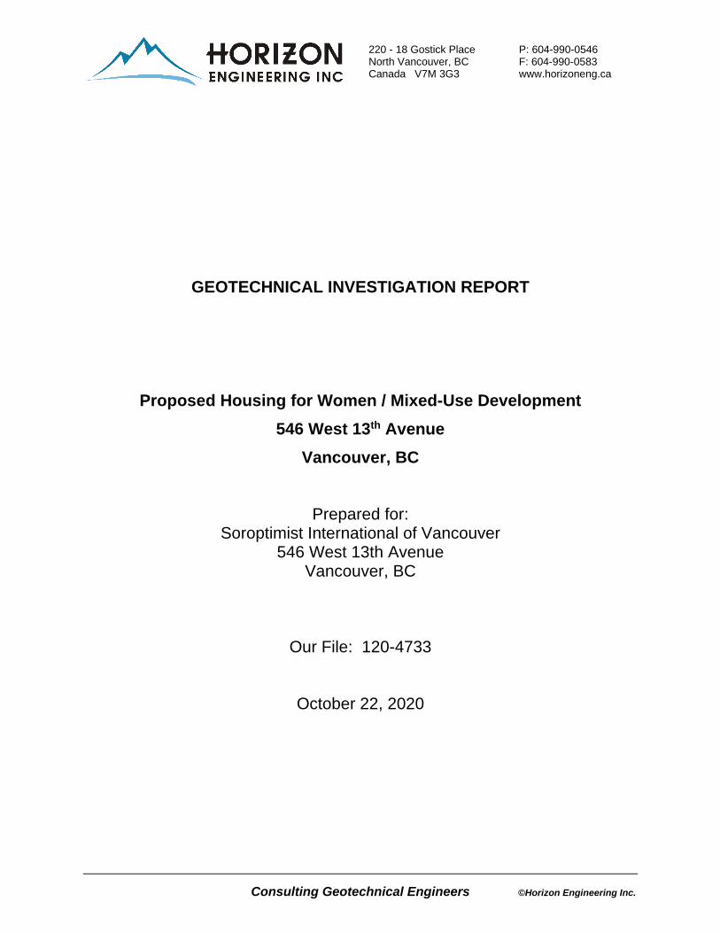
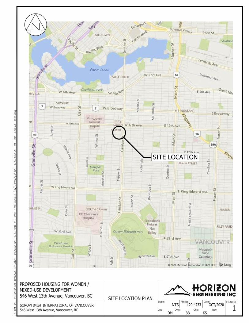
As shown in Figure 1, the site is bounded by West 13th Avenue to the north and existing, market, multi-family developments to the east, west, and south, all of which appear to include below-grade parkades. The site area is understood to encompass a footprint of approximately 1,370 square meters (14,750 square feet).
General topography in the vicinity of the site slopes down to the north, towards False Creek.
3.0 BACKGROUND INFORMATION
Reference Documents
We have been provided with the following documents specific to the subject site for the purpose of preparation of this report:
• Architectural drawings, prepared by GBL Architects, dated September 11, 2020, and • Site Survey prepared by Butler Sundvick, dated August 10, 2020.
We have also referred to the following publicly available sources to collect additional information in the vicinity of the subject site:
• City of Vancouver Online Geographic Information Systems (GIS), • Geologic Survey of Canada Map 1486A, • Vancouver’s Old Streams Map, and • others, as available and noted in this report.
Proposed Housing for Women / Mixed-Use Development Our File: 120-4733 546 West 13th Avenue, Vancouver, BC October 22, 2020 Geotechnical Investigation Report Page 2
Consulting Geotechnical Engineers ©Horizon Engineering Inc.
Proposed Development
Based on the aforementioned architectural drawings, and our conversations with the client, we understand that the proposed development comprises a 13-storey mixed-use residential building founded over two levels of below-grade parking, which is envisaged to extend to within close proximity of all property lines. Based on the architectural design sections provided to us, proposed perimeter excavation depths to allow for footing construction are expected to be in the range of 6.0 to 7.5 metres (20 to 25 feet) below existing grades. Locally deeper excavations may be required at core footings and sumps.
Surficial Geology
Based on published information available from the Geological Survey of Canada (Map 1486A), the area in the vicinity of the subject site is expected to be underlain by Vashon Drift and Capilano Sediments, which are expected to comprise lodgement and minor flow till, lenses and interbeds of substratified glaciofluvial sand to gravel, and lenses and interbeds of glaciolacustrine laminated stony silt, underlain by tertiary bedrock at a depth of less than approximately 10 metres (30 feet).
The above description is generally consistent with our experience in the vicinity of the subject site. It is noted that at 3106 Cambie Street, for which we provided geotechnical consulting services, tertiary bedrock, comprising weak to very weak, weathered sandstone, was encountered within approximately 3.0 to 4.5 metres (10 to 15 feet) of surface grades.
The tertiary bedrock in the vicinity of the site is generally anticipated to be highly weathered and thus generally excavatable by conventional equipment. However, it should be noted that zones of calcareous bedrock may be encountered which may require hydraulic splitting during construction.
Based on the Vancouver's Old Streams and the Peat, Assorted Soils, and Historical Waterways maps, the subject site is not situated within a ‘peat zone’ or a ‘soil liquefaction zone’ or within the vicinity of any documented buried streams.
Seismic Data
Based on published information from the Vancouver Building By-law 2019, Division B, Appendix C, Table C-3 for City Hall, the peak ground acceleration (PGA) for the design magnitude seismic event with a 2% probability of exceedance in 50 years (i.e. 1 in 2475 year event) is 0.369 g, where g is the gravitational acceleration. This peak ground acceleration is for firm ground conditions and is assumed to have no vertical acceleration component. The published spectral acceleration values with a 2% probability of exceedance in 50 years for different natural periods are presented in Table 1.
Table 1: Vancouver Building By-law 2019 Seismic Design Data for Vancouver (City Hall)
Sa (0.2) Sa (0.5) Sa (1.0) Sa (2.0) Sa (5.0) Sa (10.0) PGA PGV
0.848 0.751 0.425 0.257 0.080 0.029 0.369 0.553
Proposed Housing for Women / Mixed-Use Development Our File: 120-4733 546 West 13th Avenue, Vancouver, BC October 22, 2020 Geotechnical Investigation Report Page 3
Consulting Geotechnical Engineers ©Horizon Engineering Inc.
4.0 SUBSURFACE INVESTIGATION
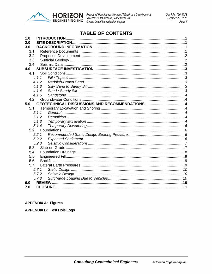
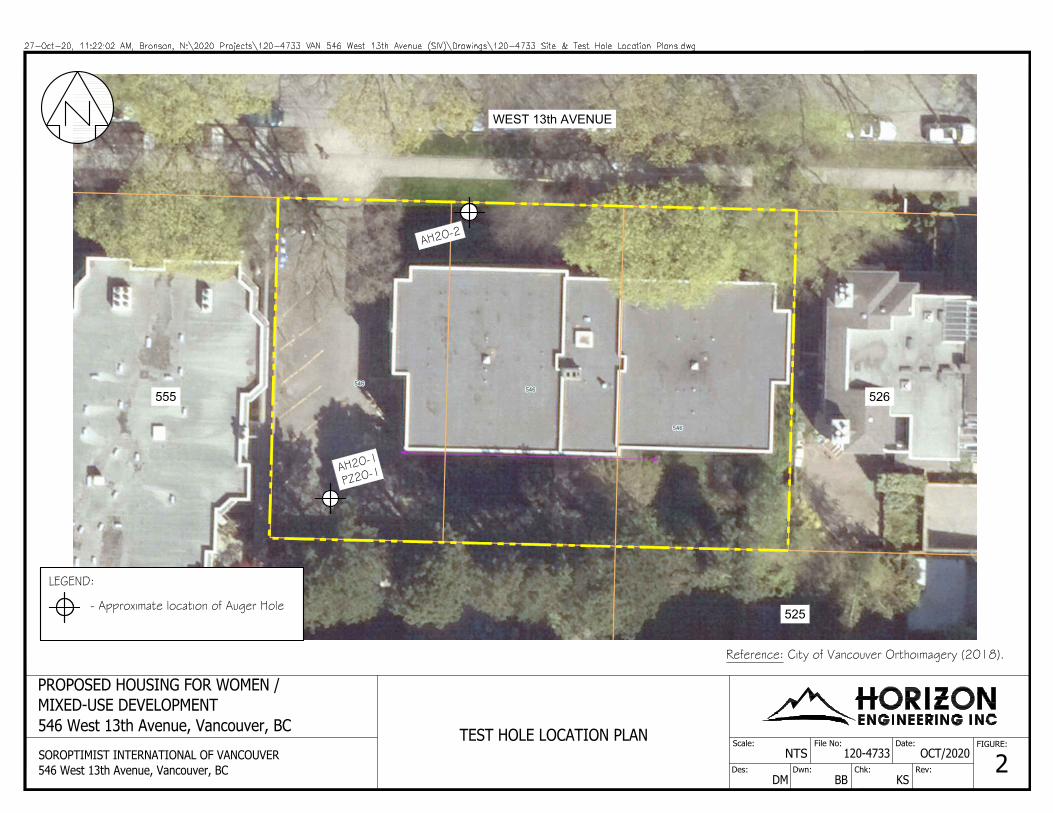
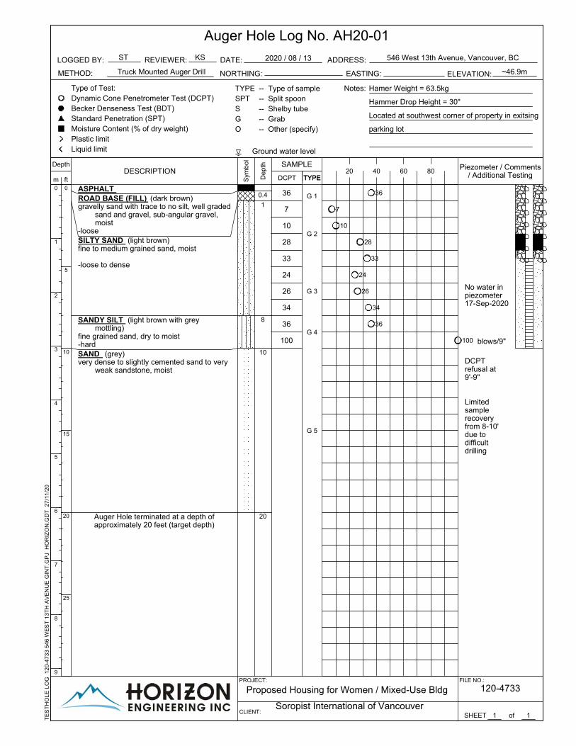
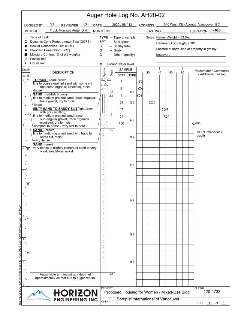
In order to characterize the subsurface soil and groundwater conditions at the subject site, a subsurface investigation program comprising two, solid stem auger test holes (AH20-1 and AH20-2) was completed on August 13, 2020. The test holes were advanced to effective refusal with depths ranging from 6.0 to 8.5 metres (20 to 28 feet) below existing site grades. Each of the augured test holes was accompanied by a Dynamic Cone Penetration Test (DCPT) sounding advanced from the ground surface until effective refusal, in order to characterize the relative density / consistency of the upper subsurface materials. In order to monitor local groundwater levels following the drilling, a standpipe piezometer was installed within one of the test holes. The subsurface investigation was carried out using a truck-mounted drill rig supplied and operated by Southland Drilling Co. The drilling was directed, and the subsurface stratigraphy was logged, by an engineer from our office. In order to reduce the risk of damaging existing, traceable, buried utility lines, a utility locate search was conducted by Western Locates prior to our subsurface investigation. The approximate locations of the aforementioned test holes are shown on Figure 2 attached to this document. During drilling, disturbed grab samples were obtained from the solid stem auger flights and returned to our laboratory for further analysis and classification.
Soil Conditions
The soil stratigraphy encountered during the subsurface investigation is briefly described following. Please refer to the test hole logs in Appendix B for detailed information.
4.1.1 Fill / Topsoil
At both test hole locations, a layer of topsoil or fill / road base was encountered. These strata were found to exist down to depths of approximately 0.3 to 0.6 metres (1.0 to 1.7 feet) below grade.
4.1.2 Reddish-Brown Sand
At AH20-02, a layer of fine to medium grained, dry to moist, reddish-brown sand with trace organics and trace fine to medium gravel was encountered beneath the topsoil layer. This stratum was found to be loose and extended to 0.7 metres (2.3 feet) below grade.
4.1.3 Silty Sand to Sandy Silt
At both test hole locations, the aforementioned soils were underlain by a light brown to light brown with grey mottling, dry to moist, silty sand to sandy silt that was inferred to be loose to compact / very stiff to hard. The silty sand to sandy silt was found to be 0.8 to 2.1 metres (2.7 to 7.0 feet) thick, extending to depths of 1.5 to 2.4 metres (5.0 to 8.0 feet) below existing site grades.
4.1.4 Sand / Sandy Silt
The silty sand to sandy silt was underlain by hard, light brown sandy silt with grey mottling at AH20-01 and very dense, brown sand at AH20-02. The sandy silt and sand were found to be dry to moist and moist, respectively. These strata were found to be 0.2 to 0.6 metres (0.8 to 2.0 feet) thick, extending to depths of to 2.4 to 3.0 metres (8.0 to 10.0 feet) below existing site grades.

Proposed Housing for Women / Mixed-Use Development Our File: 120-4733 546 West 13th Avenue, Vancouver, BC October 22, 2020 Geotechnical Investigation Report Page 4
Consulting Geotechnical Engineers ©Horizon Engineering Inc.
4.1.5 Sandstone
Grey, very dense, cemented to lightly cemented, dry to moist sand inferred to be extremely weak weathered sandstone was encountered at depths of 2.4 to 3.0 metres (8 to 10 feet). This stratum extended to the bottoms of the test holes where refusal was encountered (inferred on more competent bedrock).
Groundwater Conditions
On September 17 2020, we measured the water level in the standpipe piezometer, and it was found to be greater than 10 feet below adjacent surface grades (i.e., below the bottom of the standpipe piezometer / top of the sandstone depth).
A data logger has been installed in this piezometer to measure groundwater variations over the winter months.
5.0 GEOTECHNICAL DISCUSSIONS AND RECOMMENDATIONS
In general, it is considered that the subject site is suitable for the proposed development from a geotechnical perspective provided that the following recommendations are implemented into the overall design and construction of the project.
It is noted that supplementary investigation may be required at the site pending confirmation of City of Vancouver permitting requirements with respect to hydrogeological issues.
Temporary Excavation and Shoring
5.1.1 General
It is anticipated that the materials that will be encountered on site could be excavated using conventional hydraulic excavation equipment in good repair and fitted with a ripping tooth attachment. If large boulders and/or lenses of calcareous sandstone are encountered that require splitting for removal, boulders/sandstone which cannot be ripped and have a volume in excess of 1m3 should be defined as “rock” for contractual purposes. Volumes should be quantified in-situ (i.e., before being split) by the architect, owner, or Horizon Engineering Inc.
5.1.2 Demolition
Concurrent with removal of any below or main floor suspended slabs, we recommend that a berm of soil or concrete rubble at least 1.5 metre (5 feet) wide be placed against the interiors of below-grade perimeter foundation walls.
5.1.3 Temporary Excavation
In general, it is recommended that unshored excavation slopes be maintained with an inclination no steeper than 1.0 vertical to 1.0 horizontal in fill and topsoil, and 4.0 vertical to 3.0 horizontal in competent soils; steeper slopes may be suitable in bedrock however this should be reviewed on-site by Horizon. Unshored excavation slopes should be protected with a layer of 6 mil polyethylene sheeting, staked in place to resist wind action, and maintained regularly.
In general, it is recommended that excavated spoil and construction materials/equipment not be located adjacent to the crest of the excavation / shoring unless it has been designed for these surcharges. Any signs of instability such as tension cracks, sloughing of more than 1 ft³ or 2 ft² face area, ground movements or (changes in) groundwater seepage should be reported to Horizon Engineering immediately.
Proposed Housing for Women / Mixed-Use Development Our File: 120-4733 546 West 13th Avenue, Vancouver, BC October 22, 2020 Geotechnical Investigation Report Page 5
Consulting Geotechnical Engineers ©Horizon Engineering Inc.
As discussed in Section 3.2, we understand that the proposed perimeter footing depths will be in the range of 6.0 to 7.5 metres (20 to 25 feet) below current site grades with the excavation envisaged to approach within close proximity of the property lines on all sides. As a result, we envisage that there will be insufficient room to slope excavation faces and vertical excavation support (i.e. shoring) will be required.
5.1.3.1 Excavation Shoring
It is envisaged that excavation support using a reinforced shotcrete membrane tied back with post-tensioned soil anchors will be most suitable. This system will require permission to encroach within City of Vancouver property to the north and private properties to the east, west, and south.
If such permission is not obtained, an alternate shoring system would be required. Typically, such non-encroaching shoring systems may be associated with greater deformation at the crest of the shoring wall and would be expected to negatively impact shoring, formwork, and concrete costs and schedules as well as potentially compromise the building envelope.
During excavation shoring design and prior to excavation, it will be required to confirm the depths and extents of below-grade parking structures on the neighbouring properties to the east, west, and south in order that the excavation shoring can be designed in consideration of these structures. Therefore, permission to access these properties for this purpose will be required.
Preconstruction assessments of adjacent structures should be carried out prior to commencement of excavation.
Monitoring of the excavation shoring wall and of adjacent structures will be required throughout construction; this will be detailed on the excavation shoring drawings. It is envisaged that survey monitoring would be carried out bi-weekly or more frequently during excavation and less frequently after excavation shoring is complete. Depending on the sensitivity of adjacent structures, actual site conditions encountered during construction, and construction methodologies, vibration monitoring may be recommended to be carried out during select construction activities. Daily visual monitoring should be carried out by the contractor during excavation.
If conventional double-sided forms are used to construct perimeter foundation walls, anchors would typically be detensioned in accordance with the City of Vancouver Street Restoration Manual or private encroachment agreements (i.e. with adjacent neighbours) as backfill between the shoring and the outside of the foundation wall progresses to reach adjacent exterior grade. If single-sided forms are used, or if foundation walls are shotcreted, anchors would typically be post-grouted as installation of the excavation shoring advances provided tensioning of anchors is satisfactory. In this latter case, backfilling would not be required. It should be noted that anchors and shotcrete installed on City of Vancouver property require removal within 1.5 meters (5.0 feet) of adjacent street grades.
We would be pleased to review any draft Encroachment Agreements(s) in an effort to ensure that certain geotechnical related aspects, including regarding shoring decommissioning, are not impracticable or overly onerous.
Excavation shoring drawings, including sediment and erosion control requirements if required, will be prepared upon receipt of detailed design drawings for the proposed development. Structural drawings for the existing building at the subject site and the adjacent sites to the east, west, and south (as available) should be provided to Horizon.
Field reviews should be carried out by the Geotechnical Engineer of Record during installation of the excavation shoring. In addition, interior excavation slopes which are greater than 1.2 metres
Proposed Housing for Women / Mixed-Use Development Our File: 120-4733 546 West 13th Avenue, Vancouver, BC October 22, 2020 Geotechnical Investigation Report Page 6
Consulting Geotechnical Engineers ©Horizon Engineering Inc.
(4.0 feet) should be reviewed to confirm slope stability with respect to safe worker entry. Excavation shoring design drawings can be prepared by Horizon Engineering under separate cover.
Field review during excavation and installation of shoring should be carried out by Horizon to confirm that:
• the work site is safe for worker access, • actual buried utility locations (as determined by others) will allow installation of anchors in
the design locations, • actual soil conditions encountered are consistent with shoring design parameters, • shoring installation is in conformance with the design, • workmanship of the shoring contractor is consistent with good practice, and • deformations are consistent with expectations.
5.1.4 Temporary Dewatering
The excavation area should be kept free from standing water by installing temporary sump pumps, as necessary.
Groundwater seepage within the excavation is expected to be light but may require management during construction; this can be detailed in the hydrogeological report for the site. Off-site impacts associated with construction dewatering are anticipated to be negligible; this can also be detailed in the hydrogeological report.
Erosion and sediment control (ESC) drawings will be prepared by Horizon Engineering under separate cover. If required, this can also be for the demolition phase of the project
Foundations
5.2.1 Recommended Static Design Bearing Pressure
We envisage that the very dense sandstone materials encountered at the locations of the auger holes are suitable bearing materials for the proposed footings. At this time, we recommend that a bearing pressure of 500 kPa (10,000 psf) be used for Serviceability Limit States (SLS) design.
The Geotechnical Engineer should be provided with an opportunity to review the exposed subgrade prior to footing construction or concrete pouring.
Any loosened, softened, organic, disturbed, or otherwise deleterious material should be removed prior to footing construction. Foundation subgrades should be protected from freezing; any frozen subgrade materials should be removed after thawing. In addition, groundwater and rainwater runoff should be directed to temporary sumps, and footing subgrades should be kept free of standing water. These subgrade materials are expected to be susceptible to water softening; therefore, we recommend that the exposed subgrade be protected with 0.05 metre (2 inches) of lean concrete following Horizon's review and approval of the exposed subgrade.
5.2.2 Expected Settlement
The total settlement of footings, under static loading, designed and constructed in accordance with the above recommendations should be less than 25 mm (1 inch). Differential settlement would be expected to be less than 19 mm (3/4 inch) over a span of 9.0 metres [30 feet] or 0.002 radians angular distortion.
Proposed Housing for Women / Mixed-Use Development Our File: 120-4733 546 West 13th Avenue, Vancouver, BC October 22, 2020 Geotechnical Investigation Report Page 7
Consulting Geotechnical Engineers ©Horizon Engineering Inc.
5.2.3 Seismic Considerations
We recommend that an Ultimate Limit States bearing pressure of 1,000 kPa (20,000 psf) be used for seismic design.
Based on the geological information and Vancouver Building By-law 2019, the subject site may be classified as Site Class “B” as indicated in Table 4.1.8.4.-A in Division B, Part 4. The site coefficients for spectral acceleration, F(T), may be determined as described in Tables 4.1.8.4.-B to 4.1.8.4.-I of the Vancouver Building By-law 2019.
Slab-on-Grade
It is recommended that a 0.15 metre (6 inch) thick drainage layer of compacted 19mm (3/4 inch) clear crushed gravel be placed beneath any slab-on-grade. The underslab drainage layer should be reviewed by Horizon prior to pouring concrete for the slab-on-grade.
5.3.1.1 Soil Gas / Radon
It is recommended that a rough-in for a radon extraction system be installed beneath the slab-on-grade in order to satisfy the Vancouver Building By-law requirements to resist air leakage (5.4.1.1.(e)). This rough-in is recommended to meet the general requirements of the 2019 Vancouver Building By-law Section 9.13.4.3; namely, either:
1. a gas-permeable layer installed in the space between the air barrier system and the ground, with a radon vent pipe that has one or more inlets that allow for the effective depressurization of the gas-permeable layer, or
2. a gas-permeable layer consisting of at least 100mm of clean granular material containing not more than 10% of material that will pass a 4mm sieve (19mm clear crushed gravel is recommended and the underslab drainage layer described in Section 5.4 will serve this purpose), installed below the slab on grade. An airtight radon vent pipe at least 100mm in diameter should be installed through the slab on grade and open into each contiguous area of the granular layer.
It is envisaged that the above would meet the intent of the Vancouver Building By-law.
However, it should be noted that radon gas creates a health hazard and is linked to the second highest incidence of lung cancer in Canada (behind smoking). Radon is heavier than air and thus will tend to first collect in the sumps and pipes associated with foundation drainage in the lowest levels of the parkade. For developments where pumping is required to remove water collected in the foundation drainage system, an active mechanical system would be required to collect and discharge this gas to a vent pipe.
It is understood that there is currently no evidence to suggest either the presence or absence of radon at the subject site. Thus, it is considered prudent to monitor post-construction radon concentrations within the parkade (and perimeter drainage sump) to confirm that they are within acceptable levels (to be defined by others). If post-construction radon accumulation within the building is above 'safe' levels, connection to and active venting of the aforementioned radon vent pipe to the exterior may be required. In consideration that post-construction retrofits can be much more expensive than installations during construction, it may be desirable to install select elements of a potential, future, active radon de-pressurization system during general construction, possibly including but not limited to:

Proposed Housing for Women / Mixed-Use Development Our File: 120-4733 546 West 13th Avenue, Vancouver, BC October 22, 2020 Geotechnical Investigation Report Page 8
Consulting Geotechnical Engineers ©Horizon Engineering Inc.
• a sump for collection of radon gas (with connected perforated collection pipes extending into the underslab gravel),
• a proximate electrical connection to allow for future connection of mechanical equipment, if required, and
• an extension to the vent pipe which is to terminate outside the building such that: o the pipe is clearly labeled near the cap and, if applicable, every 1.8 m and at every
change in direction to indicate that it is intended only for the removal of radon from below the floor-on-ground,
o the termination of the vent pipe is to be located such that: it terminates minimum 1.0 m above and not less than 3.5 m in any other
direction from any air inlet, door or openable window, it terminates not less than 2 m above and not less than 3.5 m in any other
direction from a roof that supports an occupancy, it terminates not less than 1.8 m from a property line, it is shielded from the weather, the accumulation of moisture in the pipe is prevented, and it is clearly labelled “RADON VENT PIPE” every 1.2 m and at every change
in direction. The above-mentioned recommendations should be reviewed by the professional undertaking responsibility for Item 4.2 on the Schedule B2, Site and Foundation Drainage Systems (i.e., the mechanical engineering consultant).
However, given a lack of evidence to suggest the presence of radon at the site and that (to the best of our knowledge) there is no precedent nor specific requirement for a radon management system at the subject site, installation of the above-noted elements should be at the discretion of the owner/operator.
These recommendations and any requirements for radon ‘rough-in’, monitoring, collection and discharge would be moot should the City of Vancouver require that the below grade portion of the subject development be tanked.
Foundation Drainage
It is recommended that foundation drains be located around the perimeter of the building. Foundation drains could consist of 0.15 metre (6 inch) diameter, rigid, perforated, PVC pipes, with inverts 0.30 metre (12 inches) below the lowest proposed finished floor elevation. These pipes should be bedded on and surrounded by a minimum of 0.15 metre (6 inches) of 3/4 inch clear crushed gravel. A suitable filter fabric could be placed between any adjacent soil or fill and the gravel in an effort to limit migration of fine-grained materials into the drainage system. The exterior backfill materials should be hydraulically connected to the foundation drains such that water cannot accumulate and build up pressure. This is often accomplished by installing through-wall weep holes, 0.1 metre (3 inches) in diameter with a spacing of 2.4 metres (8 feet). Foundation drains should be installed with a minimum grade of 1.0%. The suitability of this system should be confirmed by the professional taking responsibility for Item 4.2 on the Letters of Assurance (Site and Foundation Drainage Systems) during construction.
Collected water should be directed to a suitable disposal system approved by the City of Vancouver. In order to satisfy the requirements of the City of Vancouver that groundwater (including perched) not be discharged into the municipal sewer following construction, it may be required to retain this water on site, possibly for re-use in green areas. This should be reviewed during the design phase. The expected groundwater flow collected in the perimeter drainage is anticipated to be minimal and can be estimated by Horizon, if required.
Proposed Housing for Women / Mixed-Use Development Our File: 120-4733 546 West 13th Avenue, Vancouver, BC October 22, 2020 Geotechnical Investigation Report Page 9
Consulting Geotechnical Engineers ©Horizon Engineering Inc.
Engineered Fill
Within the context of this report, Engineered Fill should consist of select, inert, clean, well graded granular material with less than 5% fines content by mass, 100% passing a 6-inch (150mm) sieve designation, and capable of withstanding the effects of handling, spreading, and compaction without excessive degradation or production of deleterious fines. Fine grained soil is defined as particles passing the US #200 sieve (finer than 0.075 mm diameter). The particles should be reasonably uniform in quality and free from organic materials and deleterious matter.
Engineered Fill should be placed in suitable lifts (generally 1-foot loose thickness or less) and compacted to the equivalent of at least 100% of its Maximum Dry Density determined in accordance with ASTM D698 (Standard Proctor). Field density testing should be carried out to ensure the compaction criteria are achieved and these test results should be forwarded to Horizon for review. In addition, Horizon Engineering should be given the opportunity to review the Engineered Fill material type and placement and compaction procedures.
It should be noted that even backfills compacted to the strictest criteria should be expected to experience post construction settlement in the order of 1% of the total fill thickness. Therefore, any paved areas or hard landscaping spanning between the building/backfill and adjacent, existing, ground surfaces should be designed accordingly.
The Geotechnical Engineer of Record who is responsible for the long-term performance of any settlement-sensitive structures supported on Engineered Fill should be provided with the opportunity to review the supplier's gradation and a material sample. Field density testing should be carried out on each lift of Engineered Fill placed and compacted. Density test results should be forwarded to the Geotechnical Engineer of Record for review. Field reviews should also be conducted by the Geotechnical Engineer of Record to confirm that fill placement procedures are satisfactory and density test results are representative.
Any non-commercially sourced fill proposed for use at the site should have associated documentation verifying that it is free of contaminants. This documentation should be provided to the environmental consultant for approval before any material is brought to the site.
Backfill
In order to reduce lateral soil pressures, backfill placed against the foundation or retaining walls should consist of free-draining (i.e., less than 5% fines content) granular fill. The City of Vancouver Street Restoration Manual should be referred to for acceptable material specifications and compaction criteria.
In backfilled areas, clear crushed gravel should be placed continuously on the exteriors of foundation walls to 0.15 metre (6 inches) above the through-wall weep holes. This could be covered with a 0.15 metre (6 inches) thick filter layer of pea or birdseye gravel or a layer of woven filter fabric (Nilex 4545, or approved equivalent, may be considered suitable) prior to placing any sandy backfills. The suitability of this system should be confirmed by the professional taking responsibility for Item 4.2 on the Letters of Assurance (Site and Foundation Drainage Systems) during construction.
Lateral Earth Pressures
The earth pressure on basement and retaining walls depends on a number of factors including the backfill material type, surcharge loads, backfill slope, drainage conditions, rigidity of the foundation wall, and method of construction including sequence and degree of compaction. If drainage behind the wall cannot be provided, then hydrostatic pressures should be added to these lateral earth pressures.
Proposed Housing for Women / Mixed-Use Development Our File: 120-4733 546 West 13th Avenue, Vancouver, BC October 22, 2020 Geotechnical Investigation Report Page 10
Consulting Geotechnical Engineers ©Horizon Engineering Inc.
5.7.1 Static Design
For foundation and retaining walls that will be backfilled with compacted granular material such as sand and gravel and which can move 0.2% of the wall height, or about 0.25 inch between floor slabs, then locally, the condition is presumed to be unrestrained and it is recommended that the wall be designed to resist a 35 x h (psf) [5.6 x h kPa] triangular earth pressure distribution where h is the distance from the top of the wall measured in feet [metres].
Where the backfill material will be required to support settlement sensitive structures, compaction to greater than 100% of its Standard Proctor Maximum Dry Density would be required. In this circumstance, a compaction earth pressure of 19 kPa (400 psf) uniform pressure distribution should be used in the top approximate 4.1 metres (13.5 feet). Elsewhere, backfill should be compacted to at least 95% of its Standard Proctor Maximum Dry Density.
5.7.2 Seismic Design
For seismic loading conditions, the effect of earthquake shaking can be assumed to add an additional triangular pressure to the top of the wall which decreases to zero at the base of the wall. Based on the Mononobe Okabe method (Mononobe and Matsuo, 1929; Okabe, 1924) the seismic surcharge pressure can be assumed to be 20 x (H h) (psf) [3.2 x (H-h) kPa] where h is the distance from the top of the wall and H is the total wall height measured in feet [metres].
Although the Mononobe Okabe method is suggested in the 4th edition of the Canadian Foundation Engineering Manual (2006), the equations do not account for the stiffness of the structure nor the soil structure interaction. If a more accurate determination of seismic earth pressure is required, more rigorous analytical methods such as finite element analysis to account for soil structure interaction should be carried out. We would be pleased to provide additional information regarding this type of engineering service if requested.
Seismic earth pressures are not added to the compaction earth pressure; therefore, only the greater of either the seismic or compaction earth pressures would be recommended at the corresponding depth.
5.7.3 Surcharge Loading Due to Vehicles
Surcharge loads from adjacent parking areas can be assumed to be equivalent to an additional 0.6 metre (2 feet) of soil supported against the wall.
6.0 REVIEW
It is recommended that Horizon Engineering Inc. be provided with the opportunity to review Building Permit Application drawings from the architect, structural engineer, civil engineer, mechanical engineer, and landscape architect prior to Building Permit Application in order that the recommendations in this report can be confirmed or augmented, as required.
In accordance with the 2019 Vancouver Building By-law Letters of Assurance program, the Geotechnical Engineer must provide assurance that a geotechnical design will be prepared and that field reviews in support of the design assumptions will be performed. At this time, we envisage the following components will require geotechnical design and field reviews. It is noted that the scope encompassed by these components is outlined in Appendix B of the Engineers and Geoscientists Canada Practice Guideline, Geotechnical Engineering Services for Building Projects, dated September 17, 2020.
Proposed Housing for Women / Mixed-Use Development Our File: 120-4733 546 West 13th Avenue, Vancouver, BC October 22, 2020 Geotechnical Investigation Report Page 12
Consulting Geotechnical Engineers ©Horizon Engineering Inc.
Appendix A Figures
© 2020 Microsoft Corporation © 2020 HERE
SITE LOCATION
Scale:
Des: Dwn:
File No: Date:
Chk: Rev:
FIGURE:
PROPOSED HOUSING FOR WOMEN /MIXED-USE DEVELOPMENT546 West 13th Avenue, Vancouver, BC
SOROPTIMIST INTERNATIONAL OF VANCOUVER546 West 13th Avenue, Vancouver, BC
120-4733 OCT/2020
DM BB KS
SITE LOCATION PLAN
1NTS
Scale:
Des: Dwn:
File No: Date:
Chk: Rev:
FIGURE:
PROPOSED HOUSING FOR WOMEN /MIXED-USE DEVELOPMENT546 West 13th Avenue, Vancouver, BC
SOROPTIMIST INTERNATIONAL OF VANCOUVER546 West 13th Avenue, Vancouver, BC
120-4733 OCT/2020
DM BB KS
TEST HOLE LOCATION PLAN
2NTS
Reference: City of Vancouver Orthoimagery (2018).
WEST 13th AVENUE
LEGEND:
- Approximate location of Auger Hole
AH20-1
PZ20-1
526555
AH20-2
525
Proposed Housing for Women / Mixed-Use Development Our File: 120-4733 546 West 13th Avenue, Vancouver, BC October 22, 2020 Geotechnical Investigation Report Page 13
Consulting Geotechnical Engineers ©Horizon Engineering Inc.
Appendix B Test Hole Logs
28
10
7
36
24
Auger Hole terminated at a depth ofapproximately 20 feet (target depth)
SAND (grey)very dense to slightly cemented sand to very
weak sandstone, moist
SANDY SILT (light brown with greymottling)
fine grained sand, dry to moist-hard
SILTY SAND (light brown)fine to medium grained sand, moist
-loose to dense
ROAD BASE (FILL) (dark brown)gravelly sand with trace to no silt, well graded
sand and gravel, sub-angular gravel,moist
-loose
ASPHALT
-- Type of sample-- Split spoon-- Shelby tube-- Grab-- Other (specify)
KS
Truck Mounted Auger Drill
TE
ST
HO
LE L
OG
12
0-4
733
546
WE
ST
13T
H A
VE
NU
E G
INT
.GP
J H
OR
IZO
N.G
DT
27
/11
/20
NORTHING: ~46.9m
33
m
100
36
34
26
120-4733
G 2
34
26
24
33
28
10
7
36
G 5
G 3
G 1
G 4
20
10
8
1
0.4
Limitedsamplerecoveryfrom 8-10'due todifficultdrilling
DCPTrefusal at9'-9"
36
No water inpiezometer17-Sep-2020
100 blows/9"
TYPE60
SAMPLE
Soropist International of Vancouver1
DCPTDESCRIPTION
Type of Test:Dynamic Cone Penetrometer Test (DCPT)Becker Denseness Test (BDT)Standard Penetration (SPT)Moisture Content (% of dry weight)Plastic limitLiquid limit
1
REVIEWER:
of
Proposed Housing for Women / Mixed-Use Bldg
Piezometer / Comments/ Additional Testing
Notes:TYPESPTSGO
Ground water level
PROJECT:
EASTING:
SHEET
2020 / 08 / 13
0
5
10
15
20
25
ELEVATION:
FILE NO.:
ST
Hamer Weight = 63.5kg
Hammer Drop Height = 30"
Located at southwest corner of property in exitsing
parking lot
ADDRESS:
METHOD:
DATE:
CLIENT:
Auger Hole Log No. AH20-01
Depth80
ft0
1
2
3
4
5
6
7
8
9
TYPE
546 West 13th Avenue, Vancouver, BC
20
Sym
bol
Dep
th
LOGGED BY:
40
51
47
24
4
SAND (grey)very dense to slightly cemented sand to very
weak sandstone, moist
6
7
ST
TE
ST
HO
LE L
OG
12
0-4
733
546
WE
ST
13T
H A
VE
NU
E G
INT
.GP
J H
OR
IZO
N.G
DT
27
/11
/20
METHOD:
DATE:REVIEWER:
-- Type of sample-- Split spoon-- Shelby tube-- Grab-- Other (specify)
100
Truck Mounted Auger Drill NORTHING: ~46.3m
120-4733
m
SAND (brown)fine to medium grained sand with trace to
some silt, moist-very dense
KS
G 5
100
51
47
24
4
6
7
G 8
Auger Hole terminated at a depth ofapproximately 28 feet due to auger refusal
G 6
G 4
G 3
G 2
G 1
G 7
5
SILTY SAND TO SANDY SILT (light brownwith grey mottling)
fine to medium grained sand, tracesub-angular gravel, trace organics(rootlets), dry to moist
-compact to dense / very stiff to hard
SAND (reddish brown)fine to medium grained sand, trace organics,
trace gravel, dry to moist-loose
TOPSOIL (dark brown)fine to coarse grained sand with some silt
and some organics (rootlets), moist-loose
7.2
2.3
1.7
DCPT refusal at 7'depth
Hamer Weight = 63.5kg
Hammer Drop Height = 30"
Located at north side of property in grassy
boulevard
28
60
1Soropist International of Vancouver
PROJECT:
DCPT TYPEDESCRIPTION
Type of Test:Dynamic Cone Penetrometer Test (DCPT)Becker Denseness Test (BDT)Standard Penetration (SPT)Moisture Content (% of dry weight)Plastic limitLiquid limit
ADDRESS:
SAMPLE Piezometer / Comments/ Additional Testing
EASTING:
Proposed Housing for Women / Mixed-Use Bldg
Notes:TYPESPTSGO
Ground water level
Sym
bol
20
0
5
10
15
20
25
Dep
th
0
1
2
3
4
5
6
7
8
9
2020 / 08 / 13
ELEVATION:
FILE NO.:
80
of1SHEETCLIENT:
Auger Hole Log No. AH20-02
40ft
Depth
LOGGED BY: 546 West 13th Avenue, Vancouver, BC
TYPE