Embed Size (px)
Citation preview
SUBMITTED TO: Ausenco Engineering Canada, Inc. 855 Homer Street Vancouver, B.C., Canada V6B 2W2
A JOINT REPORT BY: Shannon & Wilson, Inc. 400 N. 34th Street, Suite 100 Seattle, WA 98102 (206) 632-8020 www.shannonwilson.com
GEOTECHNICAL ENGINEERING REPORT
BHP Potash Export Terminal HOQUIAM, WASHINGTON
AND BY: Clarity Engineering LLC 12705 SW 248th Street Vashon, WA 98070 (206) 851-7914
June 2019
Shannon & Wilson No.: 101575-005 Clarify Engineering LLC No.: 124
Ausenco No.: 101051-05-RPT-0087
BHP No.: 40600-GE-RPT-00106
BHP Potash Export Terminal Geotechnical Engineering Report
101575-005 June 2019 ii
CONT
ENTS
CONTENTS
1 Introduction ................................................................................................................................ 1
2 Site and Project Description ...................................................................................................... 1
3 Subsurface Data and Conditions ............................................................................................. 2
3.1 Project Geotechnical Data ............................................................................................... 2
3.2 Historic Geotechnical Data ............................................................................................. 3
3.3 Subsurface Soil Conditions ............................................................................................. 3
3.4 Groundwater Conditions ................................................................................................ 4
4 Engineering Studies and Recommendations ......................................................................... 4
4.1 General ............................................................................................................................... 4
4.2 Design Ground Motions Return Period ........................................................................ 4
4.3 Uniform Hazard Ground Motion Response................................................................. 5
4.4 Input Strong Ground Motion Time Histories .............................................................. 5
4.5 Equivalent Linear Analysis ............................................................................................. 6
4.5.1 Shear Wave Velocity Profile .............................................................................. 6
4.5.2 Dynamic Soil Properties ..................................................................................... 7
4.5.3 Site Response Analysis Results ......................................................................... 7
4.5.4 Recommended Equivalent Linear Design Spectrum ..................................... 7
4.6 Liquefaction Susceptibility ............................................................................................. 7
4.7 Non-linear Effective Stress Model ................................................................................. 8
4.7.1 Grid, Boundary Conditions, and Dynamic Loading Input ........................... 8
4.7.2 Soil Parameters .................................................................................................... 9
4.7.3 Monitored Parameters ........................................................................................ 9
4.7.4 Results ................................................................................................................. 10
4.8 Storage Building ............................................................................................................. 10
4.8.1 Storage Building Foundations ......................................................................... 10
4.8.2 Potash Stockpile Support ................................................................................. 11
4.9 Deep Foundation Analyses ........................................................................................... 12
4.9.1 Axial Resistance ................................................................................................. 13
4.9.2 Group Lateral Resistance Analysis for Select Structures ............................. 15
4.9.3 Lateral Resistance Parameters ......................................................................... 17
BHP Potash Export Terminal Geotechnical Engineering Report
101575-005 June 2019 iii
CONT
ENTS
4.10 Transfer Tower and Conveyor Foundation Type Recommendations .................... 18
4.11 Dredge Slope Stability ................................................................................................... 18
4.12 Railcar Dumper Pit (RDP) Facility ............................................................................... 19
4.12.1 Dumper Pit Soil and Hydrogeologic Conditions .......................................... 20
4.12.2 Braced Excavation ............................................................................................. 20
4.12.2.1 Lateral Earth Pressures ..................................................................... 20
4.12.2.2 Long Term Design Uplift Pressures ............................................... 20
4.12.2.3 Groundwater Control During Railcar Dumper Pit (RDP) Excavation .............................................................................. 21
4.12.2.4 Dewatering Construction Considerations ..................................... 22
4.13 Overpass Bridge and Approach Embankments ........................................................ 22
4.13.1 Global Stability Analyses ................................................................................. 22
4.13.2 Estimated Settlements ....................................................................................... 23
4.13.3 Bridge Abutment Foundations ........................................................................ 24
4.13.3.1 Driven Pile Foundations .................................................................. 24
4.13.3.2 Settlement-Induced Downdrag Load on Driven Piles ................. 24
4.13.4 Mechanically Stabilized Earth (MSE) Walls .................................................. 25
4.14 Rail Loop ......................................................................................................................... 26
4.14.1 Cut-and-Fill Slopes ............................................................................................ 26
4.14.2 Global Stability Analyses ................................................................................. 27
4.14.3 Estimated Settlements and Mitigation Alternatives ..................................... 27
4.14.4 Rail Trackbed ..................................................................................................... 29
4.14.5 Surface and Subballast Drainage ..................................................................... 29
4.15 Pavement Design ............................................................................................................ 30
4.15.1 Subgrade Conditions ........................................................................................ 30
4.15.2 Traffic Load ........................................................................................................ 30
4.15.3 Design Approach ............................................................................................... 31
4.15.4 Hot-Mix Asphalt (HMA) Section Recommendations .................................. 31
4.15.5 Pavement Surface Drainage and Subdrainage .............................................. 32
4.16 Maintenance and Administration Building Foundations ........................................ 32
4.16.1 Deep Foundations ............................................................................................. 32
BHP Potash Export Terminal Geotechnical Engineering Report
101575-005 June 2019 iv
CONT
ENTS
4.16.2 Spread Footing Foundations Alternative ....................................................... 32
4.16.2.1 Bearing Resistance and Anticipated Movement ........................... 33
4.16.2.2 Resistance to Lateral Loads .............................................................. 33
4.17 Surface Water Infiltration .............................................................................................. 34
4.18 Buried Utilities ................................................................................................................ 35
5 Construction Considerations .................................................................................................. 36
5.1 Driven Pile Installation .................................................................................................. 36
5.1.1 Pile-driving Conditions .................................................................................... 36
5.1.2 Pile-driving Equipment .................................................................................... 36
5.1.3 Preliminary Pile Driving Criteria .................................................................... 36
5.1.4 Pile-driving Monitoring .................................................................................... 37
5.1.5 Potential Obstructions ...................................................................................... 37
5.1.6 Pile Dynamic Testing ........................................................................................ 38
5.2 Temporary Excavations ................................................................................................. 38
5.3 Fill Placement and Compaction ................................................................................... 39
5.4 Wet Weather Considerations ........................................................................................ 40
5.5 Settlement Monitoring and Instrumentation ............................................................. 41
5.6 Construction Observation ............................................................................................. 42
6 Summary of Recommendations and Recommended Future Study ................................. 42
6.1 Storage Building and Product Support Slab .............................................................. 43
6.2 Railcar Dumper Pit (RDP) Structure ........................................................................... 43
6.3 Transfer Towers and Conveyor Bents ......................................................................... 43
6.4 Marine Facility ................................................................................................................ 44
6.5 Marine Slopes ................................................................................................................. 44
6.6 Overpass Structure ......................................................................................................... 44
6.7 Maintenance and Administrative Buildings .............................................................. 44
6.8 New Rail Loop ................................................................................................................ 44
6.9 Surface Water Treatment Facilities .............................................................................. 45
7 Closure ....................................................................................................................................... 45
8 References ................................................................................................................................. 46
BHP Potash Export Terminal Geotechnical Engineering Report
101575-005 June 2019 v
CONT
ENTS
Exhibits Exhibit 4-1: Reference Time Histories ...............................................................................................6 Exhibit 4-2: FLAC Model Soil Profile and Models ..........................................................................9 Exhibit 4-3: Potash Stockpile Settlement Estimation During Operation .................................... 12 Exhibit 4-4: Pile Dimensions ............................................................................................................. 13 Exhibit 4-5: Axial Resistance Analyses Index ................................................................................ 14 Exhibit 4-6: Foundation Loading ..................................................................................................... 16 Exhibit 4-7: Dredge Cut Static Slope Stability Summary .............................................................. 19 Exhibit 4-8: Mechanically Stabilized Earth Wall Geotechnical Design Parameters .................. 25 Exhibit 4-9: Summary of HMA Pavement Design Parameters .................................................... 31 Exhibit 4-10: HMA Pavement Design Section ................................................................................ 32 Exhibit 4-11: Summary of Grain Size Analysis Infiltration Correlations ................................... 34 Exhibit 4-12: Summary of Proposed Infiltration Facilities ........................................................... 35
Figures Figure 1: Vicinity Map Figure 2: Site and Exploration Plan Figure 3: Generalized Subsurface Profile A-A' Figure 4: Generalized Subsurface Profile B-B' Figure 5: Generalized Subsurface Profile C-C' Figure 6: Cut and Fill Summary Along Rail Loop Track 1 Figure 7: Factored Bearing Resistance Versus Footing Width for Square Footings Figure 8: Factored Bearing Resistance Versus Footing Width for Strip Footings
Appendices Appendix A: Uniform Hazard Spectrum, Time Histories, and Site Response Appendix B: 2D Non-Linear Effective Stress Site Response (FLAC) Results Appendix C: Settlement Analyses Appendix D: Group Pile Analysis Results Appendix E: Axial Pile Analysis Results Appendix F: Lateral Earth Pressure and Uplift Pressure Figures Appendix G: Global Stability Analyses Important Information
BHP Potash Export Terminal Geotechnical Engineering Report
101575-005 June 2019 vi
ACRO
NYMS
ACRONYMS
2D two-dimensional AASHTO American Association of State Highway and Transportation Officials ARA ARA, Inc., ERES Division AREMA American Railway Engineering and Maintenance-of-Way Association ASCE American Society of Civil Engineers Ausenco Ausenco Engineering Canada, Inc. BHP BHP Billiton Canada Inc. CAPWAP Case Pile Wave Analysis Program cm centimeter CPT cone penetrometer test DOE Washington State Department of Ecology EPS expanded polystyrene ESU engineering soil unit FLAC Fast Lagrangian Analysis of Continua FS factor of safety GDR Geotechnical Data Report H:V Horizontal to Vertical HMA hot-mix asphalt km kilometer kN kiloNewton kN/m3 kiloNewtons per cubic meter kPa kilopascal m meter mm millimeter m3 cubic meter MCE maximum credible earthquake MPa megapascal MRE Manual for Railway Engineering MSE mechanically stabilized earth NAVD88 North American Vertical Datum of 1988 PDA pile driving analyzer Project BHP Potash Export Terminal Project PSHA Probabilistic Seismic Hazard Analysis RDP railcar dumper pit Ru pressure ratio SPS Selection Phase Study SPT Standard Penetration Test UHS uniform hazard spectrum
BHP Potash Export Terminal Geotechnical Engineering Report
101575-005 June 2019 vii
ACRO
NYMS
USGS U.S. Geological Survey WSDOT Washington State Department of Transportation
BHP Potash Export Terminal Geotechnical Engineering Report
101575-005 June 2019 1
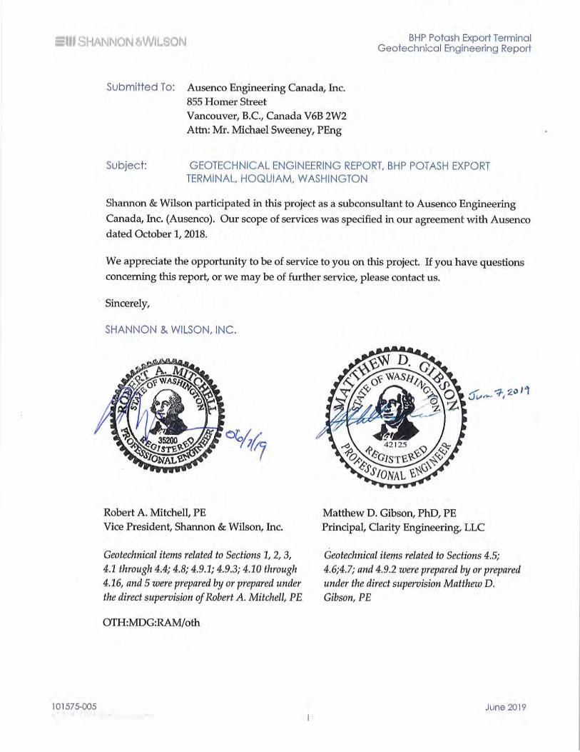
1 INTRODUCTION This Geotechnical Engineering Report presents the results of our geotechnical engineering analyses and recommendations for the BHP Potash Export Terminal Project (Project), located in Hoquiam, Washington.
This report was prepared for the exclusive use of Ausenco and BHP Billiton Canada Inc. (BHP), the Project owner. The scope of the field explorations was based on the current conceptualization of the project and discussions with Ausenco and BHP about their scope, schedule, and budget goals. This report should be made available to prospective contractors to develop their bids to build or construct the Project; however, the information provided in the report is based on factual data only and not as a warranty of subsurface conditions. Unanticipated subsurface conditions are commonly encountered and subsurface conditions cannot be fully determined by merely taking samples from borings and performing in situ tests. Additional geotechnical exploration may be required and/or desired by BHP or contractors to assess and mitigate design, construction, and operational risks identified as the Project is advanced through final design and construction.
2 SITE AND PROJECT DESCRIPTION BHP proposes to develop the site as a potash export terminal supplied by an existing rail network. The proposed Project is located about 2.5 kilometers (km) west of downtown Hoquiam, near an existing wood pulp mill and Terminal 3 on the north shore of Grays Harbor (see Figure 1). The approximately 650-meter (m)-long by 500-m-wide site was previously part of a log storage and handling area for a pulp mill. It is bordered on the west by the City of Hoquiam’s wastewater treatment facilities and wildlife viewing area. The east side of the site is bordered by an active pulp mill and export operation.
In general, the potash export terminal will be constructed as a bulk receiving, storage, and export facility. Our understanding of the facility is based on the site plan provided by Ausenco (Drawing 40600-LO-DWG-00033). Components of the facility and related infrastructure evaluated in this report include the following:
Product unloading facility and unloading pit (onshore structure)
Product storage building (onshore structure) with provision for an adjacent storage building
Product stacking and reclaiming conveyor (onshore structure)
BHP Potash Export Terminal Geotechnical Engineering Report
101575-005 June 2019 2
Administration and maintenance buildings (onshore structure)
Transfer towers (onshore and offshore structures)
Offshore berthing and mooring facilities (offshore marine structure) including: - 300-m-long access road trestle - Service platform - Transfer tower - Pivot structure for quadrant shiploader - Four-leg and two-leg quadrant supports - Mooring and berthing dolphins
Rail overpass bridge and embankments
Rail loop track
Infiltration or storage ponds
Maintenance and administration buildings
Figure 2 presents a site plan showing the location of the proposed design elements and structures.
3 SUBSURFACE DATA AND CONDITIONS We developed our conceptual geotechnical recommendations based on subsurface conditions interpretations of conditions encountered in representative subsurface explorations. Logs of subsurface explorations are presented in the Geotechnical Data Report (GDR) (Shannon & Wilson, Inc., 2019 – BHP Document Reference No. 40600-GE-RPT-00102).
Our subsurface interpretations are presented in generalized subsurface Profiles A-A’ through C-C’ (Figures 3 through 5) and described in the following sections.
3.1 Project Geotechnical Data
We completed eight onshore geotechnical borings, three overwater geotechnical borings, two observation well borings, four seismic cone penetrometer tests, and four cone penetrometer tests (CPTs) to characterize the subsurface conditions at the Project site. Boring depths ranged in depth from 6 to 57 m and CPTs ranged from 30 to 46 m below ground surface. Field methods and procedures used for these field explorations are presented in the GDR (Shannon & Wilson, Inc., 2019 – BHP Document Reference No. 40600-GE-RPT-00102).
BHP Potash Export Terminal Geotechnical Engineering Report
101575-005 June 2019 3
We performed geotechnical laboratory tests on samples retrieved from the borings to evaluate the index and engineering characteristics of the soil. These tests are presented in the GDR (Shannon & Wilson, Inc., 2019).
3.2 Historic Geotechnical Data
We collected borehole and test pit logs, CPT logs, geologic profiles, and geotechnical laboratory testing results from two previous studies conducted in the Project area by Shannon & Wilson (2008 and 2013) and Roger Lowe Associates, Inc. (1979-1980). We identified 22 previous field explorations. Explorations range in depth from 1 to 55 m below ground surface. The locations of the existing explorations are presented in Figure 2. Borehole, test pit, and CPT log; laboratory test data; and exploration plans with profile lines and the associated profiles for each previous project are presented in Appendix C.
3.3 Subsurface Soil Conditions
Our interpretations of the subsurface conditions at the site are summarized as generalized subsurface profiles in Figures 3 through 5. As indicated in the subsurface profiles, we divided the soils we encountered into six engineering soil units (ESUs):
ESU 0 – Existing Fill. This ESU consists of materials placed by humans, both engineered and nonengineered. Typically, very loose to dense, comprised of various materials, including soil, quarry spalls, construction debris, cobbles, wood chips, and other organic debris. Fill materials encountered in the Project site are likely related to the site’s previous use as a log storage and handling facility for a wood pulp mill. Based on historic aerial photography, it appears that the fill was placed to build out the land area into an existing estuary.
ESU 1 – Upper Fine-Grained with Interbedded Loose Sand. These are estuary deposits of the current and ancestral Chehalis River. The estuarine deposits are highly compressible, very soft to medium stiff, laminated silts; elastic silts; and silty clays with interbeds of sandy silts and sandy elastic silts. Local concentrations of organic-rich silt and woody debris were encountered in this upper estuarine unit.
ESU 2 – Sand-Like with Interbedded Silt. These are river or creek alluvium deposits of the current and ancestral Chehalis River, including overbank deposits. Typically, loose to medium dense, silty sand and sandy gravel. The typical Standard Penetration Test (SPT) blow counts in this alluvial layer are between 20 and 30 blows per 0.3 m onshore and 10 to 12 blows per 0.3 m offshore.
ESU 3 – Lower Fine-Grained with Interbedded Silty Sand. These deposits are similar to ESU 1, but with less organic components. In some areas, ESU 3 was encountered as stiff to very stiff. Typical SPT blow counts in this lower estuarine layer range between 1 and 6 blows per 0.3 m offshore and on the southern and western onshore portions of the site. For the northeast onshore portion the site, typical SPT blow counts in this lower

BHP Potash Export Terminal Geotechnical Engineering Report
101575-005 June 2019 4
estuarine layer range between 10 and 20 blows per 0.3 m (see eastern portion of Profile B-B’).
ESU 4 - Dense Sand and Gravel and Stiff Silt. These deposits are a mixture of stiff to hard silts, gravelly sand, and sandy gravels interpreted as a transitionary alluvium unit between ESU 3 above and the dense outwash gravel (ESU 5) below. ESU 4 appears to be discontinuous throughout the site.
ESU 5 – Dense Outwash Gravel. These are interpreted as advance glacial outwash that consists of dense to very dense, sandy gravel. The typical SPT blow count in this advance glacial outwash layer would be between 50 blows per 0.3 m and 50 blows per 0.1 m. The approximate elevation of the top of the advance glacial outwash layer is between -40 and -45 m (North American Vertical Datum of 1988 [NAVD88]).
3.4 Groundwater Conditions
The observed groundwater levels in borings OB-01-18 and OB-02-18, as well as in observation wells MW-1-18 through MW-7-18 installed by others, ranged from 0.2 to 2.2 m below the ground surface (Shannon & Wilson, Inc., 2019). Wells MH-1-18 through MH-7-18 were monitored by BergerABAM on a quarterly basis from March 28, 2018, to December 18, 2018 (BergerABAM, 2018). Groundwater data from dataloggers during November and December 2018 are presented in the GDR (Shannon & Wilson, Inc., 2019 – BHP Document Reference No. 40600-GE-RPT-00102).
4 ENGINEERING STUDIES AND RECOMMENDATIONS 4.1 General
Based on our current understanding of the proposed offshore facilities and the results of our geotechnical studies, we have developed geotechnical recommendations related to the seismic design including strong ground motions, liquefaction potential, lateral spreading, and lateral pile resistance as described in the following sections.
4.2 Design Ground Motions Return Period
We understand that the seismic design ground motion levels of the project will be in accordance with the American Society of Civil Engineers (ASCE) Minimum Design Loads for Buildings and Other Structures, ASCE 7-05, (ASCE, 2006), as required by ASCE 61-14. The ASCE 7-05 uses maximum credible earthquake (MCE), which corresponds to the 2,475-year return period ground motion for design.
BHP Potash Export Terminal Geotechnical Engineering Report
101575-005 June 2019 5
4.3 Uniform Hazard Ground Motion Response
Input ground motions required for the site response analysis correspond to a uniform hazard spectrum (UHS) (firm ground target spectrum). The UHS was developed based on the ASCE 7-05 spectral hazard values, the 150 percent median deterministic spectrum, and the lower limit deterministic values (ASCE 7-05 Figure 21.2-1). The ASCE 7-05 spectral values were obtained for Site Class C/D boundary, which corresponds to an average shear wave velocity (Vs30) of 360 m per second in the dense to very dense advance glacial outwash gravel encountered at the project site. The 150 percent deterministic spectrum was calculated using ground motion prediction equations and the seismological inputs from the 2008 U.S. Geological Survey Probabilistic Seismic Hazard Analysis (USGS PSHA) performed for this site. The lower limit deterministic spectrum was calculated using the procedure described in ASCE 7-05 Section 21.2. Figure A-1 presents the firm ground UHS for the project site (Appendix A).
4.4 Input Strong Ground Motion Time Histories
We used deaggregation results from the 2008 USGS PSHA performed for this site to guide the selection of input time histories. The deaggregation results provide seismic source contribution, earthquake magnitude, and source-to-site distance that are the most significant contributors to ground motion hazard for a particular return period and spectral acceleration.
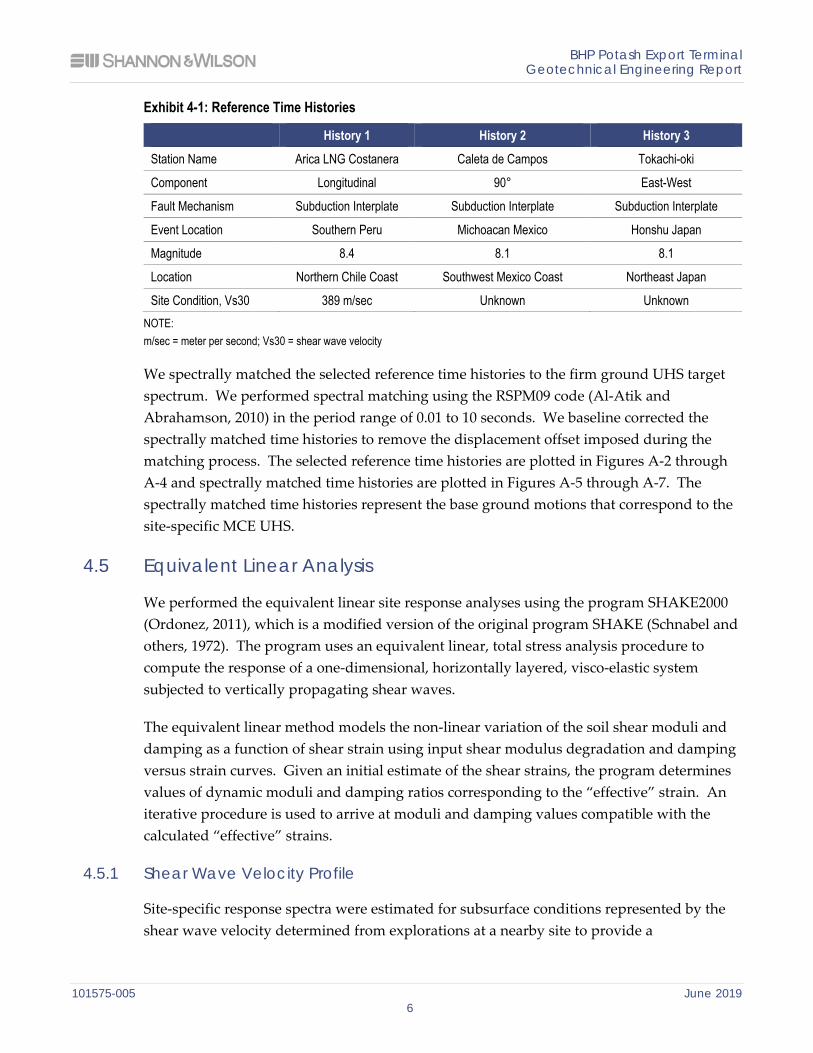
For preliminary design, we selected a total of three recorded strong ground motion acceleration time histories (i.e., seed motions or reference time histories) with characteristics similar (i.e., tectonic source, magnitude, distance, etc.) to those identified in the hazard deaggregation. We reviewed available earthquake time history databases and selected reference time histories that have similar characteristics, such as the seismogenic source and response spectrum shape. The reference time histories we selected for the MCE ground motion level are presented in Exhibit 4-1.
BHP Potash Export Terminal Geotechnical Engineering Report
101575-005 June 2019 6
Exhibit 4-1: Reference Time Histories
History 1 History 2 History 3 Station Name Arica LNG Costanera Caleta de Campos Tokachi-oki
Component Longitudinal 90° East-West
Fault Mechanism Subduction Interplate Subduction Interplate Subduction Interplate
Event Location Southern Peru Michoacan Mexico Honshu Japan
Magnitude 8.4 8.1 8.1
Location Northern Chile Coast Southwest Mexico Coast Northeast Japan
Site Condition, Vs30 389 m/sec Unknown Unknown NOTE: m/sec = meter per second; Vs30 = shear wave velocity
We spectrally matched the selected reference time histories to the firm ground UHS target spectrum. We performed spectral matching using the RSPM09 code (Al-Atik and Abrahamson, 2010) in the period range of 0.01 to 10 seconds. We baseline corrected the spectrally matched time histories to remove the displacement offset imposed during the matching process. The selected reference time histories are plotted in Figures A-2 through A-4 and spectrally matched time histories are plotted in Figures A-5 through A-7. The spectrally matched time histories represent the base ground motions that correspond to the site-specific MCE UHS.
4.5 Equivalent Linear Analysis
We performed the equivalent linear site response analyses using the program SHAKE2000 (Ordonez, 2011), which is a modified version of the original program SHAKE (Schnabel and others, 1972). The program uses an equivalent linear, total stress analysis procedure to compute the response of a one-dimensional, horizontally layered, visco-elastic system subjected to vertically propagating shear waves.
The equivalent linear method models the non-linear variation of the soil shear moduli and damping as a function of shear strain using input shear modulus degradation and damping versus strain curves. Given an initial estimate of the shear strains, the program determines values of dynamic moduli and damping ratios corresponding to the “effective” strain. An iterative procedure is used to arrive at moduli and damping values compatible with the calculated “effective” strains.
4.5.1 Shear Wave Velocity Profile
Site-specific response spectra were estimated for subsurface conditions represented by the shear wave velocity determined from explorations at a nearby site to provide a
BHP Potash Export Terminal Geotechnical Engineering Report
101575-005 June 2019 7
representation of the range of shear wave velocities that could be encountered at the site. The soil model for the site response analyses was developed to reflect measured and estimated site-specific soil properties, and to consider variations and uncertainties in the thicknesses, shear wave velocities, and dynamic soil properties of the various soil units. To provide a representation of the potential variability in subsurface conditions across the site, two profiles were developed for the off-shore area near the marine terminal, the shoreline area, and the upland area for a total of four shear wave velocity profiles. Figure A-8 presents the generalized shear wave velocity profile used for the soil model and soil types used in the site response analyses.
4.5.2 Dynamic Soil Properties
Input properties for equivalent linear analysis include the shear wave velocity and soil unit weight along with shear modulus degradation and damping vs. strain curves. The published curves used in our analyses included those by Electric Power Research Institute (1993) for sand, Vucetic and Dobry (1991) for clay, and Rollins and others (1998) for gravel.
4.5.3 Site Response Analysis Results
The program SHAKE2000 (Ordonez, 2011) was used to perform an equivalent-linear total stress analysis. Figure A-9 shows the ground motion response spectra at the ground surface for the various assumed shear wave velocity profiles for the design ground motion level as well as the geometric mean of the results.
4.5.4 Recommended Equivalent Linear Design Spectrum
We developed the ground surface acceleration design spectrum from the site-specific ground response spectra for MCE ground motion level. The recommended MCE spectrum at the ground surface was determined as the larger of the site-specific spectrum or 80 percent of the ASCE 7-05 code-based spectrum. The ASCE 7-05 code-based spectrum corresponds to Site Class E. The recommended MCE spectrum is shown in Figure A-9.
4.6 Liquefaction Susceptibility
Liquefaction susceptibility was evaluated using the Boulanger and Idriss (2014) empirical model for SPT and CPT explorations. The results of this evaluation indicate that the cohesionless soil in ESU 0 and ESU 2 and the interbedded sand and silty sand layers of ESU 1 and ESU 3 are susceptible to liquefaction. Based on plasticity indices of the cohesive silts and clays of ESU 1 and ESU 3, liquefaction is not expected to occur. However, cyclic loading of these cohesive soils may result in a shear strength reduction of approximately 20 percent.
BHP Potash Export Terminal Geotechnical Engineering Report
101575-005 June 2019 8
4.7 Non-linear Effective Stress Model
Evaluations of site-specific non-linear soil response including the effects of dynamic pore pressure generation were performed to evaluate the soil liquefaction and lateral spreading effects on the offshore structures induced by MCE ground motions. Lateral spread evaluations were conducted using the two-dimensional (2D) finite difference program Fast Lagrangian Analysis of Continua (FLAC).
4.7.1 Grid, Boundary Conditions, and Dynamic Loading Input
The 2D model geometry was chosen with the focus on evaluating slope deformations. The model included the river bottom, slopes on both sides of the channel, assumed dredge pocket geometry, and the upland land of the project site. The bottom of the dredge pocket was assumed at -14 m with a slope of 3.5 Horizontal to 1 Vertical (3.5H:1V). The full model is 1,800-m-wide with the zero-station located at the toe of the dredged slope. The model extends 1,300 m north of the toe to include the offshore structures and the proposed storage building. The model extends 500 m south of the toe of the slope and includes the 170-m dredged channel area and approximated slope on the south side of the channel. The base of the model is located at elevation -50 m (NAVD88) within the dense gravel. The bathymetry data provided by Ausenco indicates that the mudline on the south side of the channel slopes upwards to an elevation of -4 m (NAVD88). However, for boundary condition purposes to achieve free field conditions, the slope was brought up to be equal to the elevation of the ground surface on land, +5 m (NAVD88).
The zone sizes of the 2D model varied depending on the stiffness of the material. The zone’s height increases with depth starting at about 0.5 m at the surface and increased to about 1 m at the contact with the gravel. The zone height in the dense gravel was 2 m. The horizontal dimension of the zones varies from 2 to 4 m. A 2-m zone width was constant in the slope area near the offshore structures and below the storage building.
The firm ground motions were applied to the base of the model as a time-dependent horizontal shear stress. FLAC’s quiet base formulation was applied to the base of the model, which creates a compliant base condition and produces an upward propagating shear wave from the applied ground motion. The sides of the model were attached to each other to model free field motion. These modeling techniques were used to reduce the undesirable reflection of waves off the model boundaries and back into the model.
Initial values of total vertical stress were set based on a uniform material total unit weight of 17 kiloNewtons per cubic meter (kN/m3). The initial values of horizontal stress were set based on assumed at-rest lateral earth pressure coefficients of 0.5. The model was then stepped with all assigned soil parameters to equilibrium to calculate the initial stress and
BHP Potash Export Terminal Geotechnical Engineering Report
101575-005 June 2019 9
equilibrium state. Pore pressures were set by applying a phreatic ground water surface at elevation zero. Effective stresses are calculated internally by FLAC based on current pore pressures and total stresses in the model.
4.7.2 Soil Parameters
For the purposes of these analyses, the cohesionless soil (fill and sand alluvium) strength was modeled using the PM4Sand constitutive equations developed at University of California, Davis (Boulanger and Ziotopoulou, 2017). The PM4Sand model is calibrated to liquefy at about 90 to 95 percent excess pore pressure ratio and about 3 to 4 percent shear strain. The strength, modulus, and cyclic resistance for the PM4Sand model is related to an equivalent, normalized, clean sand cone tip resistance, (qc1n)cs, as described in the model documentation. The tip resistance was calculated using the Boulanger and Idriss empirical method (Boulanger and Idriss, 2014).
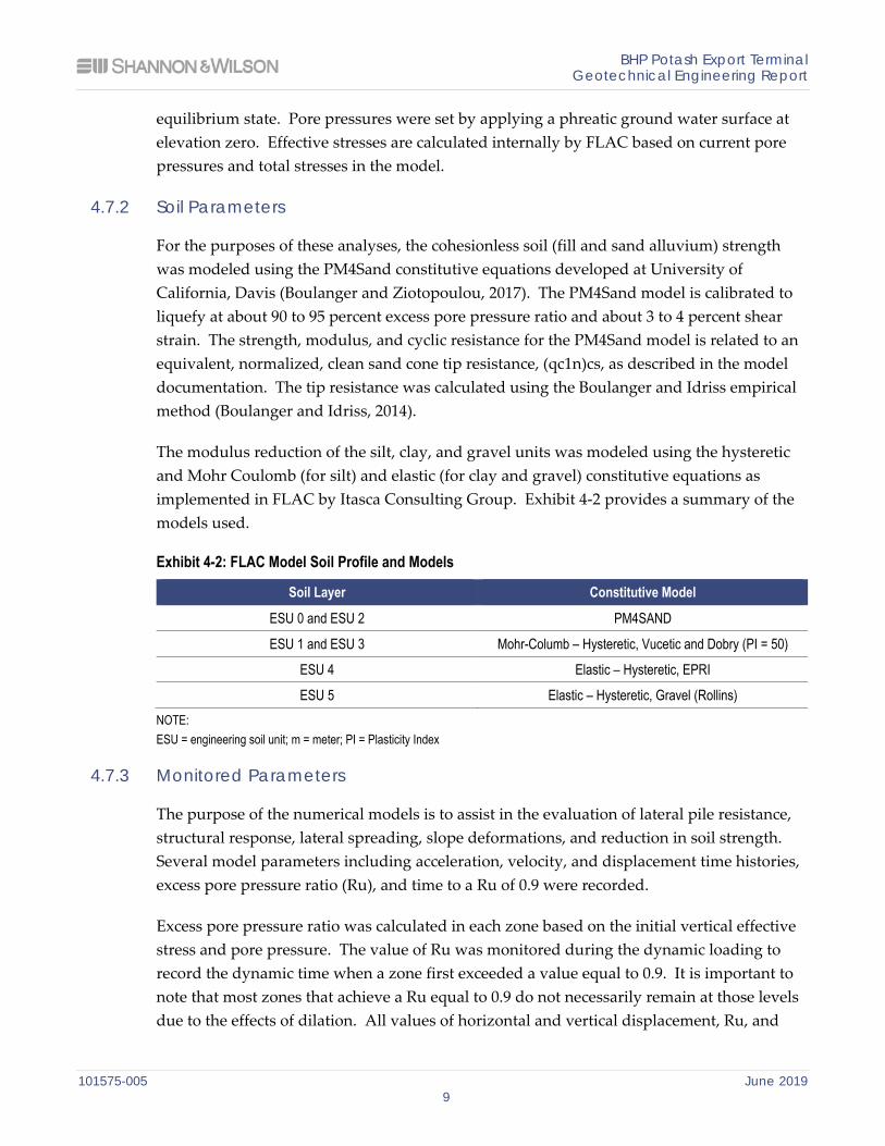
The modulus reduction of the silt, clay, and gravel units was modeled using the hysteretic and Mohr Coulomb (for silt) and elastic (for clay and gravel) constitutive equations as implemented in FLAC by Itasca Consulting Group. Exhibit 4-2 provides a summary of the models used.
Exhibit 4-2: FLAC Model Soil Profile and Models
Soil Layer Constitutive Model
ESU 0 and ESU 2 PM4SAND
ESU 1 and ESU 3 Mohr-Columb – Hysteretic, Vucetic and Dobry (PI = 50)
ESU 4 Elastic – Hysteretic, EPRI
ESU 5 Elastic – Hysteretic, Gravel (Rollins) NOTE: ESU = engineering soil unit; m = meter; PI = Plasticity Index
4.7.3 Monitored Parameters
The purpose of the numerical models is to assist in the evaluation of lateral pile resistance, structural response, lateral spreading, slope deformations, and reduction in soil strength. Several model parameters including acceleration, velocity, and displacement time histories, excess pore pressure ratio (Ru), and time to a Ru of 0.9 were recorded.
Excess pore pressure ratio was calculated in each zone based on the initial vertical effective stress and pore pressure. The value of Ru was monitored during the dynamic loading to record the dynamic time when a zone first exceeded a value equal to 0.9. It is important to note that most zones that achieve a Ru equal to 0.9 do not necessarily remain at those levels due to the effects of dilation. All values of horizontal and vertical displacement, Ru, and
BHP Potash Export Terminal Geotechnical Engineering Report
101575-005 June 2019 10
time to Ru = 0.9 throughout the model were recorded in a data file every 0.1 second of ground motion time.
4.7.4 Results
Excess pore pressure ratios, lateral deformations, and times to liquefaction were recorded in the 2D numerical models. These results are shown in Figures B-3 through B-5. In general, all the sand units liquefied in the model within the beginning third of the time histories. This was expected given the relatively large peak ground acceleration of 0.9 g and long durations from the Cascadia subduction zone earthquake hazard that dominates the site. Lateral deformation is controlled by the extents of the sand unit, dredge pocket geometry, and the depth of the channel offshore. The average upland extent of lateral deformations from the three ground motions exceeding about 500 millimeters (mm) of displacement is approximately 1,000 m from the Quadrant structure. A summary of the lateral deformations near the offshore and shoreline structures are presented in Figure B-5 (Appendix B). These lateral deformation profiles form the basis for the evaluations of kinematic loading on the offshore pile groups.
4.8 Storage Building
The storage building is approximately 402 m long and 87 m wide in plan. We understand that deformation criteria for these foundations are less than 25 mm for vertical settlement. In between these foundations is the flexible slab that supports the 10-m-high potash pile. As described in the subsurface conditions section, the storage building is underlain by units of soft plastic silt/clay and loose to medium dense sand. The silt and clay soil are relatively recent deposits that are highly compressible.
4.8.1 Storage Building Foundations
The potash storage building is about 402 m long with a gable-shaped roof and is approximately 43 m tall and 87 m wide. The gable-shaped roof connects directly to the building foundations. The building foundations are not connected to the potash support slab, thus the building foundations and support slab have different settlement criteria. Given the total storage building foundation settlement tolerance of 25 mm provided by Ausenco and the settlement sensitive nature of the subsurface soil, the storage building foundations should be founded on deep foundations. The deep foundations should extend into the very dense outwash gravels below. Axial capacities and lateral pile group analyses results are presented in the deep foundations section. Based on the vertical loads, lateral loads, and pile layout with approximate pile spacing of 6 m provided to us by Ausenco, we estimate that the facility could be supported using 600-mm-diameter, open-ended, steel pipe
BHP Potash Export Terminal Geotechnical Engineering Report
101575-005 June 2019 11
piles that are founded in the gravel layer and are approximately 52 m long. Axial capacity and lateral group analysis results for these piles is presented in the deep foundation section.
4.8.2 Potash Stockpile Support
The potash is planned to be stored in the storage building on a structural slab. The interior stockpile slab is not connected to the main building foundations. We understand the potash product will be stored in two stockpiles, each approximately 190 m long by 56 m wide, with a triangular cross-sectional shape approximately 18 m tall. An initial target potash slab settlement criteria of 150 mm was provided by Ausenco. For the purposes of settlement and stockpile stability evaluations, we assumed the potash will have a density of 11.8 kN/m3 and internal friction angle of 33 degrees.
We evaluated settlement and stability of the potash stockpile slab considering four different foundation design options:
Option 1: Allow the stockpile slab to settle without enhancing or mitigating the settlement sensitive soil;
Option 2A and 2B: Preload the existing subsurface profile to reduce post-construction primary consolidation settlement. Option 2A assumes the preload is placed on unimproved ground and Option 2B assumes wick drains are installed to increase the speed of consolidation settlement;
Option 3: Improve the upper silt and clay units with the use of timber piles and a geogrid reinforced earth mat and allow the lower clays to settle; and
Option 4: Support the potash product with a structural slab founded on steel pipe piles driven to the dense gravel unit.
For the unimproved case in the first scenario, the factor of safety (FS) against deep-seated global stability failure beneath the stockpile is less than 1.0; therefore, Option 1 does not meet the performance criteria.
Options 2A and 2B ,the preload scenarios, assume that preload fill is left in place for a year and that the facility begins operation six months after preload fill is removed. For a 12-month preloading program with about 10 m of surcharge, the stockpile external stability FS is greater than 1.5.
A stockpile external stability failure mechanism for Options 3 and 4 are assumed to not occur given that the timber or steel piles would transfer the stockpile bearing load down to the medium dense sand and gravel layers, respectively. The timber pile case (Option 3) assumes timber piles will transfer the potash stockpile load below upper clay and silt layers to the medium dense sand and lower silt and clay layers.
BHP Potash Export Terminal Geotechnical Engineering Report
101575-005 June 2019 12
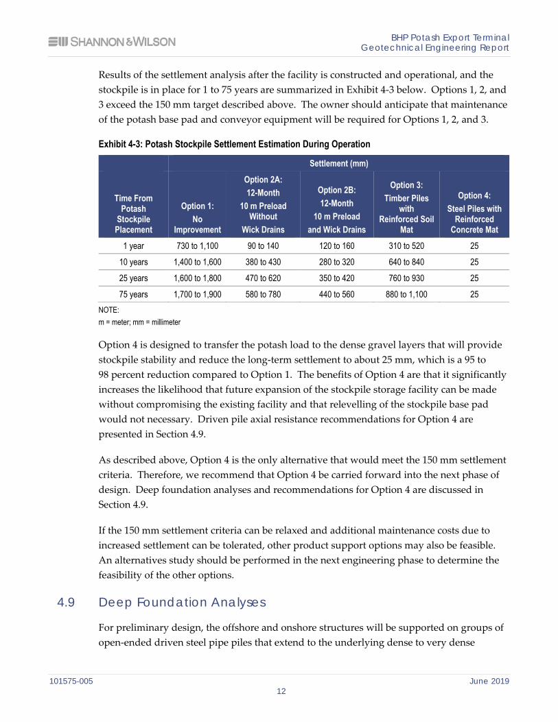
Results of the settlement analysis after the facility is constructed and operational, and the stockpile is in place for 1 to 75 years are summarized in Exhibit 4-3 below. Options 1, 2, and 3 exceed the 150 mm target described above. The owner should anticipate that maintenance of the potash base pad and conveyor equipment will be required for Options 1, 2, and 3.
Exhibit 4-3: Potash Stockpile Settlement Estimation During Operation
Settlement (mm)
Time From Potash
Stockpile Placement
Option 1: No
Improvement
Option 2A: 12-Month
10 m Preload Without
Wick Drains
Option 2B: 12-Month
10 m Preload and Wick Drains
Option 3: Timber Piles
with Reinforced Soil
Mat
Option 4: Steel Piles with
Reinforced Concrete Mat
1 year 730 to 1,100 90 to 140 120 to 160 310 to 520 25
10 years 1,400 to 1,600 380 to 430 280 to 320 640 to 840 25
25 years 1,600 to 1,800 470 to 620 350 to 420 760 to 930 25
75 years 1,700 to 1,900 580 to 780 440 to 560 880 to 1,100 25 NOTE: m = meter; mm = millimeter
Option 4 is designed to transfer the potash load to the dense gravel layers that will provide stockpile stability and reduce the long-term settlement to about 25 mm, which is a 95 to 98 percent reduction compared to Option 1. The benefits of Option 4 are that it significantly increases the likelihood that future expansion of the stockpile storage facility can be made without compromising the existing facility and that relevelling of the stockpile base pad would not necessary. Driven pile axial resistance recommendations for Option 4 are presented in Section 4.9.
As described above, Option 4 is the only alternative that would meet the 150 mm settlement criteria. Therefore, we recommend that Option 4 be carried forward into the next phase of design. Deep foundation analyses and recommendations for Option 4 are discussed in Section 4.9.
If the 150 mm settlement criteria can be relaxed and additional maintenance costs due to increased settlement can be tolerated, other product support options may also be feasible. An alternatives study should be performed in the next engineering phase to determine the feasibility of the other options.
4.9 Deep Foundation Analyses
For preliminary design, the offshore and onshore structures will be supported on groups of open-ended driven steel pipe piles that extend to the underlying dense to very dense
BHP Potash Export Terminal Geotechnical Engineering Report
101575-005 June 2019 13
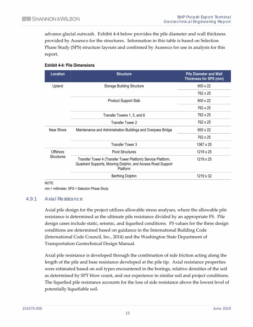
advance glacial outwash. Exhibit 4-4 below provides the pile diameter and wall thickness provided by Ausenco for the structures. Information in this table is based on Selection Phase Study (SPS) structure layouts and confirmed by Ausenco for use in analysis for this report.
Exhibit 4-4: Pile Dimensions
Location Structure Pile Diameter and Wall Thickness for SPS (mm)
Upland Storage Building Structure 600 x 22
762 x 25
Product Support Slab 600 x 22
762 x 25
Transfer Towers 1, 5, and 6 762 x 25
Transfer Tower 2 762 x 25
Near Shore Maintenance and Administration Buildings and Overpass Bridge 600 x 22
762 x 25
Transfer Tower 3 1067 x 25
Offshore Structures
Pivot Structures 1219 x 25
Transfer Tower 4 (Transfer Tower Platform) Service Platform, Quadrant Supports, Mooring Dolphin, and Access Road Support
Platform
1219 x 25
Berthing Dolphin 1219 x 32 NOTE: mm = millimeter; SPS = Selection Phase Study
4.9.1 Axial Resistance
Axial pile design for the project utilizes allowable stress analyses, where the allowable pile resistance is determined as the ultimate pile resistance divided by an appropriate FS. Pile design cases include static, seismic, and liquefied conditions. FS values for the three design conditions are determined based on guidance in the International Building Code (International Code Council, Inc., 2014) and the Washington State Department of Transportation Geotechnical Design Manual.
Axial pile resistance is developed through the combination of side friction acting along the length of the pile and base resistance developed at the pile tip. Axial resistance properties were estimated based on soil types encountered in the borings, relative densities of the soil as determined by SPT blow count, and our experience in similar soil and project conditions. The liquefied pile resistance accounts for the loss of side resistance above the lowest level of potentially liquefiable soil.
BHP Potash Export Terminal Geotechnical Engineering Report
101575-005 June 2019 14
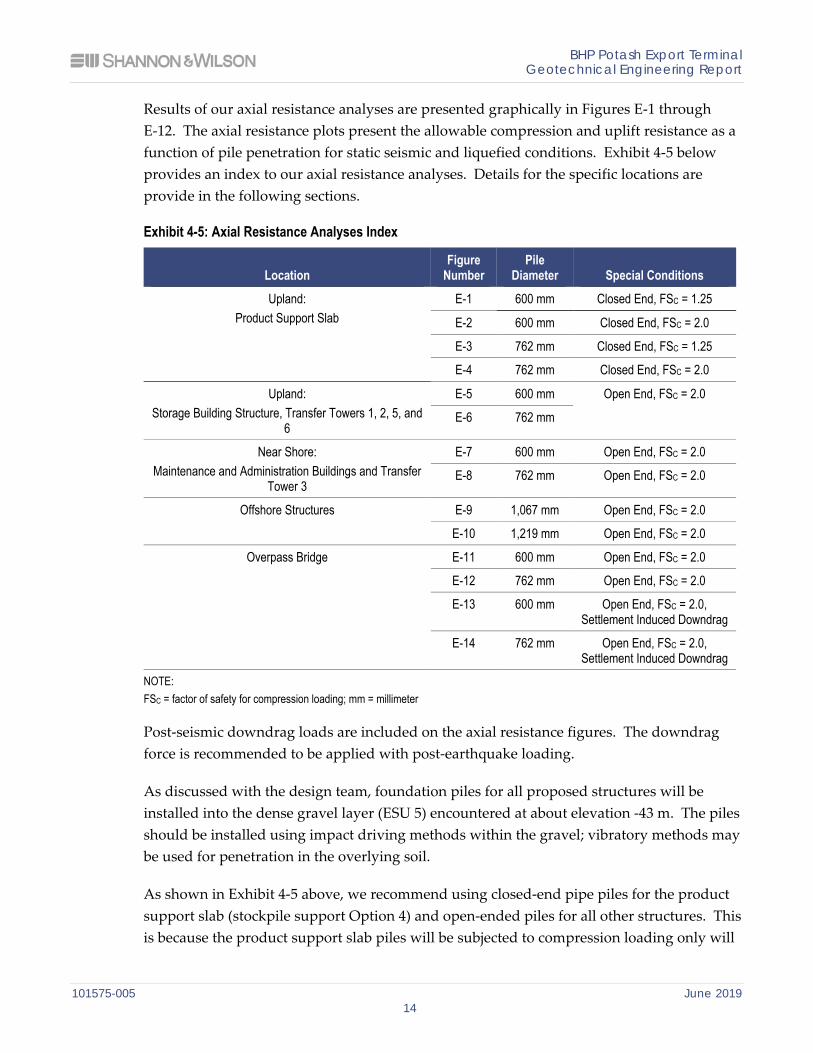
Results of our axial resistance analyses are presented graphically in Figures E-1 through E-12. The axial resistance plots present the allowable compression and uplift resistance as a function of pile penetration for static seismic and liquefied conditions. Exhibit 4-5 below provides an index to our axial resistance analyses. Details for the specific locations are provide in the following sections.
Exhibit 4-5: Axial Resistance Analyses Index
Location Figure
Number Pile
Diameter Special Conditions Upland:
Product Support Slab E-1 600 mm Closed End, FSC = 1.25
E-2 600 mm Closed End, FSC = 2.0
E-3 762 mm Closed End, FSC = 1.25
E-4 762 mm Closed End, FSC = 2.0
Upland: Storage Building Structure, Transfer Towers 1, 2, 5, and
6
E-5 600 mm Open End, FSC = 2.0
E-6 762 mm
Near Shore: Maintenance and Administration Buildings and Transfer
Tower 3
E-7 600 mm Open End, FSC = 2.0
E-8 762 mm Open End, FSC = 2.0
Offshore Structures E-9 1,067 mm Open End, FSC = 2.0
E-10 1,219 mm Open End, FSC = 2.0
Overpass Bridge E-11 600 mm Open End, FSC = 2.0
E-12 762 mm Open End, FSC = 2.0
E-13 600 mm Open End, FSC = 2.0, Settlement Induced Downdrag
E-14 762 mm Open End, FSC = 2.0, Settlement Induced Downdrag
NOTE: FSC = factor of safety for compression loading; mm = millimeter
Post-seismic downdrag loads are included on the axial resistance figures. The downdrag force is recommended to be applied with post-earthquake loading.
As discussed with the design team, foundation piles for all proposed structures will be installed into the dense gravel layer (ESU 5) encountered at about elevation -43 m. The piles should be installed using impact driving methods within the gravel; vibratory methods may be used for penetration in the overlying soil.
As shown in Exhibit 4-5 above, we recommend using closed-end pipe piles for the product support slab (stockpile support Option 4) and open-ended piles for all other structures. This is because the product support slab piles will be subjected to compression loading only will
BHP Potash Export Terminal Geotechnical Engineering Report
101575-005 June 2019 15
not require uplift or lateral resistance from embedment into the gravel layer. To improve tip bearing resistance for these closed-end piles, we recommend driving the piles a minimum of 2 pile diameters into the dense gravel layer (ESU 5). For open-ended piles, we recommend a minimum pile penetration of 5 diameters into the gravel.
These axial resistance analyses are applicable to a single pile or pile groups with a center-to-center pile spacing greater than 2.5 diameters.
A common static FS for pile design for bridges, buildings, and other structures under compression loading is 2.0. Based on discussions with Ausenco, we considered use of a lower FS value equal to 1.25. We understand use of this lower FS value results in approximately half the number of piles necessary to support the product slab than with a FS of 2.0. A lower FS increases the risk of exceeding the pile settlements we have estimated. However, given the known potash stockpile geometry and the potash unit density, we estimate the increase in risk of exceeding the initial 150-mm target settlement criteria to be small. It is worth noting that the uncertainty in settlement prediction with the lower FS for Option 4 is likely lower than that of Option 3. These risks were discussed and agreed to by Ausenco. For these reasons, the compression loading axial capacities shown in Figures E-1 and E-3 are shown with a FS of 1.25. The same analyses with compression loading FS values of 2.0 are included as Figures E-2 and E-4 for reference.
Timber pile recommendations for stockpile support Option 3 are provided below:
Timber piles that have a 300-mm butt diameter and spaced 1,200-mm center-to-center could be used. The piles should be installed in a triangular pattern;
Timber piles should be driven to the middle of the loose to medium dense sands resulting in a pile length of approximately 20 m; and
The geogrid reinforced structural fill would be approximately 1-m-thick. The structural fill is reinforced with layers of geogrid placed every 300 mm such that potash loads are distributed to the timber piles. The fill between the layers of geogrid should consist of well-graded sand and gravel.
4.9.2 Group Lateral Resistance Analysis for Select Structures
We evaluated the lateral resistance of the pile groups for the various offshore and onshore structures considering the static and seismic loading cases based on based on the SPS structure layouts (2017) provided by Ausenco. Static loading conditions considered static soil behavior. The seismic loading cases included liquefied soil behavior with combinations of inertial and kinematic loading. The liquefied loading case considers the post-liquefied residual strengths of the soil layers that are liquefiable. The pile group configurations for each structure, soil conditions, and corresponding loading were input into the computer
BHP Potash Export Terminal Geotechnical Engineering Report
101575-005 June 2019 16
program GROUP by Ensoft. The piles were modeled as elastic elements within GROUP. Initial GROUP analyses were performed with a range of horizontal forces applied with liquefied soil properties to evaluate the overall stiffness of the pile foundations for each structure. The horizontal forces were applied along the strong and weak axis of the structures. We understand that this stiffness will be used to calibrate the stiffness of Ausenco’s structural finite element models. Ausenco’s calibrated finite element models were used to estimate inertial loads for each structure from the design response spectrum. The results of our GROUP stiffness calibration analyses are shown in Figures D-1 through D-14.
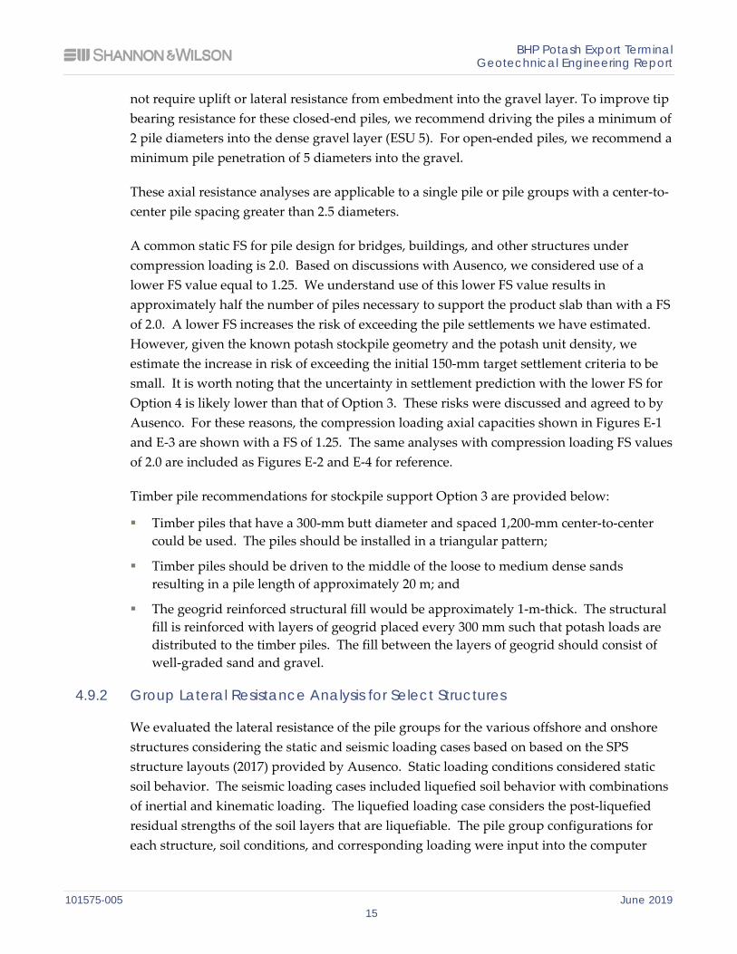
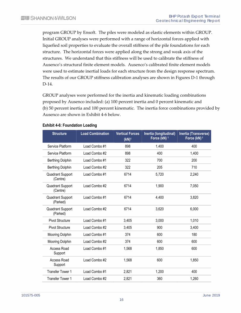
GROUP analyses were performed for the inertia and kinematic loading combinations proposed by Ausenco included: (a) 100 percent inertia and 0 percent kinematic and (b) 50 percent inertia and 100 percent kinematic. The inertia force combinations provided by Ausenco are shown in Exhibit 4-6 below.
Exhibit 4-6: Foundation Loading
Structure Load Combination Vertical Forces (kN)1
Inertia (longitudinal) Force (kN) 1
Inertia (Transverse) Force (kN) 1
Service Platform Load Combo #1 898 1,400 400
Service Platform Load Combo #2 898 400 1,400
Berthing Dolphin Load Combo #1 322 700 200
Berthing Dolphin Load Combo #2 322 205 710
Quadrant Support (Centre)
Load Combo #1 6714 5,720 2,240
Quadrant Support (Centre)
Load Combo #2 6714 1,900 7,050
Quadrant Support (Parked)
Load Combo #1 6714 4,400 3,820
Quadrant Support (Parked)
Load Combo #2 6714 3,620 6,000
Pivot Structure Load Combo #1 3,405 3,000 1,010
Pivot Structure Load Combo #2 3,405 900 3,400
Mooring Dolphin Load Combo #1 374 600 180
Mooring Dolphin Load Combo #2 374 600 600
Access Road Support
Load Combo #1 1,568 1,850 600
Access Road Support
Load Combo #2 1,568 600 1,850
Transfer Tower 1 Load Combo #1 2,821 1,200 400
Transfer Tower 1 Load Combo #2 2,821 360 1,260
BHP Potash Export Terminal Geotechnical Engineering Report
101575-005 June 2019 17
Structure Load Combination Vertical Forces (kN)1
Inertia (longitudinal) Force (kN) 1
Inertia (Transverse) Force (kN) 1
Transfer Tower 2 Load Combo #1 3,734 1,630 500
Transfer Tower 2 Load Combo #2 3,734 500 1,630
Transfer Tower 3 Load Combo #1 2,821 1,200 400
Transfer Tower 3 Load Combo #2 2,821 360 1,260
Transfer Tower 4 (Transfer Tower
Platform)
Load Combo #1 1,282 1650 730
Transfer Tower 4 (Transfer Tower
Platform)
Load Combo #2 1,282 730 1,650
Transfer Towers 5 and 6
Load Combo #1 2,129 900 280
Transfer Towers 5 and 6
Load Combo #2 2,129 270 910
Storage Building (Non-Reclaimer)
Load Combo #2 7,255 0 4,285
Storage Building (Reclaimer)
Load Combo #2 7,645 0 4,285
NOTES:: Load Combo #1: DE: 100% Y (transverse)+ 30% X (longitudinal) Load Combo #2: DE: 30% Y (transverse)+ 100% X (longitudinal) kN = kiloNewton
For the load combinations with non-zero kinematic forces, we evaluated two scenarios where the inertial forces were applied in the same direction and opposite direction of kinematic loading. Note that for Transfer Tower 3 structure, a GROUP analysis with non-linear pile properties was performed to estimate plastic strains for the 50 percent inertial and 100 percent kinematic load case. The GROUP results were plotted on figures that include deflection, shear, moment, axial stress, and pile curvature as a function of elevation. The figures are numbered D-15 through D-51.
4.9.3 Lateral Resistance Parameters
Recommended soil parameters for lateral resistance analyses using the computer program GROUP are presented in Table D-1 in Appendix D. We provide these parameters to allow the structural designer to evaluate shear, moment, and displacements for the proposed foundations if the pile types, group geometries, or loading parameters change during final design.
BHP Potash Export Terminal Geotechnical Engineering Report
101575-005 June 2019 18
4.10 Transfer Tower and Conveyor Foundation Type Recommendations
We evaluated the feasibility of supporting the transfer towers and conveyor structure on deep foundations and shallow spread footings. In summary, because the upland site is underlain by about 40 to 50 m of interbedded soft, compressible silt and liquefiable sand, we recommend these structures be supported by deep foundations that extend into the dense gravel below. Deep foundation analyses and recommendations are provided in Section 4.9.
We do not recommend supporting these structures on spread footings for the following reasons:
Relatively shallow foundations would be subject to similar lateral spreading displacements as the surrounding ground surface. Based on our FLAC simulations, we anticipate the ground along these structures could displace toward the shore between 1,000 and 7,000 mm following the design seismic event (see Figure B-5).
Similarly, relatively shallow foundations would be subject to large liquefaction-induced settlements. Our liquefaction analyses suggest settlements could range from about 100 mm to about 600 mm following the design seismic event.
The structures would be subject to significant long-term static settlements due to consolidation of the soft estuarine deposits. The amount and duration of settlements would depend on the size of the footings, the shape of the footings, the magnitude of the long-term dead loads, the depth of the footings, and the weight of the material the footings are backfilled with.
4.11 Dredge Slope Stability
From the provided bathymetry, the existing slope angles range from 3.5H:1V to 6H:1V. Along the lower portions of the slope, the locally slope angle is flatter than the overall slope averaging approximately 6H:1V. The upper portions of the slope have steeper slope angles of up to 3.5H:1V. Based on extrapolation of the nearby subsurface conditions, it appears that the lower flatter angle slopes are associated with the sandy soils while the upper steeper slopes are associated with the silty clay soils. We assume that these slope angles are likely the combined result of erosional and slope stability processes.
Based on discussions with Ausenco, we understand that a 2.5H:1V slope is desired to reduce dredge quantities and permitting issues. We performed slope stability evaluations for four slope inclinations between 2.5H:1V to 6H:1V and three assumed subsurface conditions. These three assumed subsurface conditions consist of an all sand slope, silt over sand slope as described above, and an all silt slope. The soil strength ratio (strength to vertical effective stress) for the silt layer was assumed to be 0.24 and a minimum shear strength of 12 kilopascal (kPa). The friction angle assumed for the sand layer was 33 degrees. The
BHP Potash Export Terminal Geotechnical Engineering Report
101575-005 June 2019 19
bottom of the slope was assumed to be -14 m (NAVD88) and the top of the slope was 0 m (NAVD88).
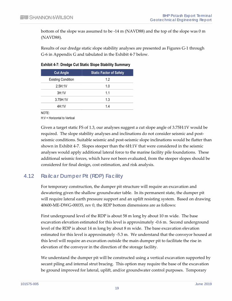
Results of our dredge static slope stability analyses are presented as Figures G-1 through G-6 in Appendix G and tabulated in the Exhibit 4-7 below.
Exhibit 4-7: Dredge Cut Static Slope Stability Summary
Cut Angle Static Factor of Safety
Existing Condition 1.2
2.5H:1V 1.0
3H:1V 1.1
3.75H:1V 1.3
4H:1V 1.4 NOTE: H:V = Horizontal to Vertical
Given a target static FS of 1.3, our analyses suggest a cut slope angle of 3.75H:1V would be required. The slope stability analyses and inclinations do not consider seismic and post-seismic conditions. Suitable seismic and post-seismic slope inclinations would be flatter than shown in Exhibit 4-7. Slopes steeper than the 6H:1V that were considered in the seismic analyses would apply additional lateral force to the marine facility pile foundations. These additional seismic forces, which have not been evaluated, from the steeper slopes should be considered for final design, cost estimation, and risk analysis.
4.12 Railcar Dumper Pit (RDP) Facility
For temporary construction, the dumper pit structure will require an excavation and dewatering given the shallow groundwater table. In its permanent state, the dumper pit will require lateral earth pressure support and an uplift resisting system. Based on drawing 40600-ME-DWG-00035, rev 0, the RDP bottom dimensions are as follows:
First underground level of the RDP is about 58 m long by about 10 m wide. The base excavation elevation estimated for this level is approximately -0.6 m. Second underground level of the RDP is about 14 m long by about 8 m wide. The base excavation elevation estimated for this level is approximately -5.3 m. We understand that the conveyor housed at this level will require an excavation outside the main dumper pit to facilitate the rise in elevation of the conveyor in the direction of the storage facility.
We understand the dumper pit will be constructed using a vertical excavation supported by secant piling and internal strut bracing. This option may require the base of the excavation be ground improved for lateral, uplift, and/or groundwater control purposes. Temporary
BHP Potash Export Terminal Geotechnical Engineering Report
101575-005 June 2019 20
dewatering wells within the excavation may also be necessary to mitigate uplift / base heave instability during construction depending on construction methods.
4.12.1 Dumper Pit Soil and Hydrogeologic Conditions
The subsurface and hydrogeologic conditions assumed for our evaluations of lateral earth pressures, uplift pressures and temporary groundwater control for the RDP structure and excavation are based on our interpretation of CPT-04 and Boring B-09-18. Our interpretation of the subsurface conditions at the dumper pit are depicted in Profile C-C’ (Figure 5). Our subsurface and hydrogeologic assumptions consist of:
Groundwater elevation at the surface.
Loose to medium dense fill (a mixture of sand with silt, silty sand, silt, and clay) from ground surface (about elevation 5 m) to about elevation 0 m.
Soft clay from about elevations 0 to -4 m.
Loose to medium dense sand with silt from about elevations -4 to -8 m.
Intermediate loose silt layer from elevations –8 to –10 m.
Interlayered silty sand and sand with silt from about elevations -10 to -20 m.
Soft to medium stiff silt and clay from elevations -20 to -40 m
4.12.2 Braced Excavation
The braced RDP excavation would consist of excavation walls formed by secant drilled shafts which are constructed to overlap. The overlap provides soil support and a water boundary. The secant shafts would need to be supported by internal bracing.
4.12.2.1 Lateral Earth Pressures
The secant shaft wall should be designed for three loading conditions: (a) static earth pressures and hydrostatic water pressures, (b) earthquake forces and hydrostatic water pressures, and (c) post-earthquake earth pressures that account for the strength reduction to soils susceptible to liquefaction and the associated increase in pore water pressure. Pressures for these three scenarios are shown in Figures F-1 to F-3 in Appendix F. Additional lateral loading that may be induced by surface loading near the wall can be evaluated with the recommendations in Figure F-4.
4.12.2.2 Long Term Design Uplift Pressures
The facility will also be subject to a net uplift pressure given that the structure is about 10 m below the groundwater table and permanent groundwater control will not be used. Uplift pressures will be based on the pore pressure in the ground. During non-seismic conditions,
BHP Potash Export Terminal Geotechnical Engineering Report
101575-005 June 2019 21
the groundwater level should be assumed to be at the ground surface. During a design level earthquake, liquefaction of the subsurface cohesionless soils is expected. Liquefaction will cause the pore pressures to increase, thus increasing the buoyant forces on the structure base. The uplift pressures can be resisted by a combination of excavation wall side friction, tiedowns installed through the base of the excavation, and a soil-concrete base plug. These forces and side resistances are shown in Figure F-5.
4.12.2.3 Groundwater Control During Railcar Dumper Pit (RDP) Excavation
Given the high groundwater levels at the RDP site, some form of temporary dewatering, partial depressurization, or ground improvement will likely be required to mitigate uplift pressures during construction until permanent uplift support is provided. One approach to mitigate for uplift during construction could be to use temporary dewatering to partially or fully depressurize groundwater pressures. Preliminary flow rates and potential well quantities are provided below. Other approaches may be feasible, such as excavation and base plug installation in the wet or use of ground improvement (e.g., deep soil mixing or jet grouting). We recommend that a contractor be engaged to evaluate the benefits of various RDP construction methods that could be used. Impacts from dewatering/derpressurizing could be partially mitigated by the use of injection wells or trenches
The base of the first underground level of the RDP excavation terminates in clay near the top of the underlying sand unit 1, and the base of the second level of the RDP excavation terminates in interlayered silt, silty sand, and sand with silt about 3 m above the top of the underlying sand unit 2. Assuming a design groundwater elevation near the ground surface and a target safety factor of 1.2 against hydrostatic uplift on the excavation subgrade, we estimate the following temporary groundwater drawdown requirements:
First underground level of RDP: 6 m of drawdown in sand unit 1 (to about elevation -2 m) and 4 m of drawdown in sand unit 2 (to about elevation 0 m).
Second underground level of RDP: dewatering and excavation through sand unit 1 and 9 m of drawdown in sand unit 2 (to about elevation -5 m).
We also used the numerical groundwater flow modeling to evaluate dewatering and depressurization well quantity, spacing, depth, and discharge rates assuming the presence of secant piles on all four sides of the RDP excavation. The required drawdowns can be achieved using 10 wells constructed to elevation -6 m, 5 wells on each side of the RDP excavation spaced about 10 to 15 m apart. These wells would be used to dewater sand unit 1 and overlying pervious soils. In addition, one well installed to elevation -15 m located inside the shoring of the second level excavation would be used to depressurize sand unit 2. Well construction would consist of the following:
Minimum 600-mm-diameter borehole.
BHP Potash Export Terminal Geotechnical Engineering Report
101575-005 June 2019 22
300-mm-diameter Schedule 40 polyvinyl chloride well casing and screen.
Well screen: machine-slotted 0.5 mm slots.
Filter product: Glacier product #8720.
Bentonite annular seal above well screen to ground surface.
One pump capable of 300 cubic meter (m3) per day under 20 m of head and capable of running in dry conditions.
Ten pumps each capable of 25 m3 per day under 12 m of head and capable of running in dry conditions.
Discharge piping and facilities to accommodate systemwide flow rates up to 550 m3 per day.
We estimate that dewatering system would produce total discharge rates of about 550 m3
per day during initial operation, and a stabilized rate of about 350 m3 per day.
4.12.2.4 Dewatering Construction Considerations
Dewatering well installation should be in accordance with state and local regulations and we assume permits and/or variances will be obtained by others. The excavation is likely to encounter perched or pocketed groundwater, even after the dewatering system is functioning, which may require sumps and/or trench drains. Power should be supplied to the pumps from portable generators (if line power is not available) and a backup generator and automatic transfer switch should be connected to the dewatering wells. Sediment settling, treatment, and disposal of dewatering system discharge have not been considered at this time and will be addressed in final design.
4.13 Overpass Bridge and Approach Embankments
We understand primary access to the site and vehicle access to the shore will be accomplished using a new overpass bridge to the facility on the south side of the site from Airport Way. The location of the proposed overpass bridge is shown in Figure 2.
We understand the overpass bridge will be single span and will likely be supported by driven steel pile foundations. Preliminary design drawings provided by Ausenco indicate the bridge approaches consist of 2H:1V fill slopes up to about 50 m from the abutments where the slopes transition to mechanically stabilized earth (MSE) retaining walls.
4.13.1 Global Stability Analyses
We performed global stability analyses for the overpass bridge approach embankment and abutment wall. These analyses and our results are presented in Appendix G.
BHP Potash Export Terminal Geotechnical Engineering Report
101575-005 June 2019 23
We modeled the approach embankments using both traditional compacted granular backfill and lightweight expanded polystyrene (EPS) geofoam using a target FS of 1.3 for long-term conditions and 1.2 for short-term, construction conditions. We obtained these target FS values for both fill material types. We did not perform seismic stability analyses for slopes.
For the bridge abutment, we used a target FS of 1.5 for long-term conditions and 1.2 for short-term, construction conditions and 1.1 for seismic and post-seismic (liquefied) conditions. We understand the preliminary design concept for the bridge abutments is to support the bridge deck with deep foundations located in front of MSE abutment retaining walls. MSE wall design recommendations are provided in Section 4.13.4.
Our stability analyses indicate that staged construction techniques (i.e., constructing the fill in stages and waiting for the underlying soils to consolidate and gain strength) are necessary and use of one or more high strength basal reinforcement layers extend over the fill transverse width of the approach embankment (see Figure G-11) to achieve adequate static FS values. However, as shown in Figures G-12 and G-13, the seismic and post-seismic (liquefied) FS values we obtained for the MSE wall configuration were below the target FS of 1.1 (regardless of the high strength basal layers). Therefore, in some form of ground improvement would likely be required beneath the MSE approach and abutment walls. Possible ground improvement options could consist of:
Preloading with wick drains
Stone columns
Deep soil mixing
As an alternative to the MSE wall design approach, a lightweight fill (e.g., EPS geofoam or low-density cellular concrete) approach could be used for the abutment walls and approach fill. Stability analyses considering this alternative are presented as Figures G-13 and G-14. A lightweight fill approach would provide several benefits:
Improved global stability for both static and seismic conditions.
Allows for rapid construction (no need for staged construction).
Allows embankment and abutment settlements to be reduced or eliminated. Lightweight fill would also address the static downdrag issues discussed in the next two sections.
4.13.2 Estimated Settlements
Details of the overpass bridge approach settlement analysis are presented in Appendix C. The settlement analysis for the overpass approaches assume regular weight fill will be used
BHP Potash Export Terminal Geotechnical Engineering Report
101575-005 June 2019 24
without any mitigation of the subgrade. Based on our calculations, we estimate up to about 1,000 mm of settlement could take place over a 75-year period.
Appendix C also presents settlement with time and settlement with elevation results at the proposed pile locations for the south approach. We estimate up to about 400 mm of settlement at the pile location over a 75-year period. We understand that the approach fill will be constructed well ahead of the bridge and its foundations to avoid significant downdrag on the deep foundation elements.
Our settlement analyses did not consider the use of lightweight fill for the approach embankments or abutment walls. In our experience, lightweight fill would be well suited for the subsurface conditions encountered at this site. Paired with overexcavation, a lightweight fill embankment can be designed to impose little to no net increase in vertical stress on the underlying soft soils, thereby greatly reducing settlements.
4.13.3 Bridge Abutment Foundations
4.13.3.1 Driven Pile Foundations
We understand the overpass bridge piers will be supported by steel pile foundations driven into advance outwash gravel (ESU 5). Axial resistance figures for the overpass piles are provided as Figures E-9 through E-12 in Appendix E. Lateral resistance parameters are provided in Table D-1 in Appendix D.
4.13.3.2 Settlement-Induced Downdrag Load on Driven Piles
As described above, construction of the approach embankments will cause compression of the soft soils above the deep gravels. This settlement will occur gradually over time and cause the soil around the abutment piles to settle sufficiently (greater than a relative movement between the shaft and surrounding soil of 1 centimeter [cm]) to result in the development of downdrag loads on the piles. In other words, the downward displacement of the surrounding soil will cause the skin friction resistance around the piles to act downward, thereby adding load to the piles.
The nominal shaft resistance available to support structure loads was estimated by considering only the positive side and base resistance below the lowest layer contributing to the downdrag (i.e., the layer above the deep gravel). The piles should designed to consider downdrag loads under the structural limit state, by adding the factored downdrag loads to the factored loads from the structure. Downdrag loads should not be deducted from geotechnical axial resistance, as the nominal base resistance of the pile is estimated for a displacement of about 5 percent of the pile diameter, such that the shaft movement would essentially negate the downdrag force. In other words, the pile section should be designed
BHP Potash Export Terminal Geotechnical Engineering Report
101575-005 June 2019 25
to carry the loads from the bridge deck and the downdrag load; however, the downdrag load should not be used to determine the required embedment depth of the piles. We provide the downdrag loads for the structural team to consider in the structural limit state.
As noted above, another approach to avoid downdrag loading conditions is to construct the approach embankments and abutment walls using lightweight fill. Using a combination of excavation of existing material and low unit weight fill materials, these approach structures can be designed to produce settlements small enough to not cause downdrag conditions on the piles. In addition to this benefit and those described in the previous section, use of lightweight fill would reduce the risk of differential settlement between the bridge deck and approach slab resting on the abutment walls.
4.13.4 Mechanically Stabilized Earth (MSE) Walls
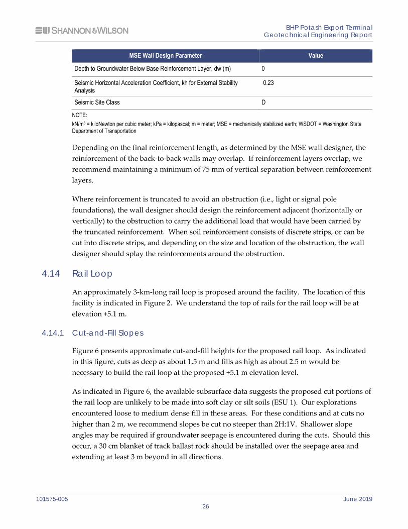
We recommend using a minimum reinforcement width over wall height ratio of 0.7, or 2.5 m, whichever is greater. The reinforcement lengths may need to be increased to meet internal; external (bearing resistance, sliding and overturning); or compound stability requirements. These failure modes should be evaluated by the MSE wall designer as these failure modes depend on the particular reinforcement type and spacing selected by the wall designer. Recommended parameters for use in internal and external stability analyses are provided in Exhibit 4-8 below.
Exhibit 4-8: Mechanically Stabilized Earth Wall Geotechnical Design Parameters
MSE Wall Design Parameter Value
Retained Fill WSDOT Common Borrow
Unit Weight, ϒ (kN/m3) 20
Effective Friction Angle, Ф' (degrees) 34
Cohesion, c' (kPa) 0
Reinforced Zone Fill WSDOT Gravel Borrow
Unit Weight, ϒ (kN/m3) 20
Effective Friction Angle, Ф ' (degrees) 38
Cohesion, c' (kPa) 0
Foundation Soil Existing Fill
Unit Weight, ϒ (kN/m3) 17
Effective Friction Angle, Ф' (degrees) 32
Cohesion, c' (kPa) 0
BHP Potash Export Terminal Geotechnical Engineering Report
101575-005 June 2019 26
MSE Wall Design Parameter Value
Depth to Groundwater Below Base Reinforcement Layer, dw (m) 0
Seismic Horizontal Acceleration Coefficient, kh for External Stability Analysis
0.23
Seismic Site Class D
NOTE: kN/m3 = kiloNewton per cubic meter; kPa = kilopascal; m = meter; MSE = mechanically stabilized earth; WSDOT = Washington State Department of Transportation
Depending on the final reinforcement length, as determined by the MSE wall designer, the reinforcement of the back-to-back walls may overlap. If reinforcement layers overlap, we recommend maintaining a minimum of 75 mm of vertical separation between reinforcement layers.
Where reinforcement is truncated to avoid an obstruction (i.e., light or signal pole foundations), the wall designer should design the reinforcement adjacent (horizontally or vertically) to the obstruction to carry the additional load that would have been carried by the truncated reinforcement. When soil reinforcement consists of discrete strips, or can be cut into discrete strips, and depending on the size and location of the obstruction, the wall designer should splay the reinforcements around the obstruction.
4.14 Rail Loop
An approximately 3-km-long rail loop is proposed around the facility. The location of this facility is indicated in Figure 2. We understand the top of rails for the rail loop will be at elevation +5.1 m.
4.14.1 Cut-and-Fill Slopes
Figure 6 presents approximate cut-and-fill heights for the proposed rail loop. As indicated in this figure, cuts as deep as about 1.5 m and fills as high as about 2.5 m would be necessary to build the rail loop at the proposed +5.1 m elevation level.
As indicated in Figure 6, the available subsurface data suggests the proposed cut portions of the rail loop are unlikely to be made into soft clay or silt soils (ESU 1). Our explorations encountered loose to medium dense fill in these areas. For these conditions and at cuts no higher than 2 m, we recommend slopes be cut no steeper than 2H:1V. Shallower slope angles may be required if groundwater seepage is encountered during the cuts. Should this occur, a 30 cm blanket of track ballast rock should be installed over the seepage area and extending at least 3 m beyond in all directions.
BHP Potash Export Terminal Geotechnical Engineering Report
101575-005 June 2019 27
We understand Ausenco is planning to construct the fill embankments with subballast fill slopes of 3H:1V and ballast slopes of 2H:1V. These slope angles are appropriate for the range of fill heights proposed, in our opinion.
4.14.2 Global Stability Analyses
We evaluated global stability for a section of rail where the propose embankment would be constructed between an existing City of Hoquiam sewage lagoon dike and an existing pond (see Figure G-1 in Appendix G). We selected this location because we anticipate very soft ground conditions and presence of the existing pond could pose slope instability risks to the proposed tracks.
Our track embankment slope stability analyses for the pond area are presented as Figures G-15 through G-18 in Appendix G. Details for these analyses are provide in the Appendix G text.
In summary, our global stability analyses for the pond section indicated that the target FS of 1.3 could not be attained with an unreinforced soil embankment. To obtain adequate FS values, we included structural elements in the form of sheet piles (see Figure G-16) or relatively small section embankment support piles.
We note that the pile configurations we used in our stability analyses would address slope instability but not settlement of the rail embankment under the weight of the trains.
We note that although we consider the pond area to be the worst-case portion of the alignment from a global stability perspective, large portions of the rail loop alignment are proposed through existing wetlands (see Figures 2 and 6) where we do not have subsurface data. Subsurface data for these areas should be obtained during final design.
4.14.3 Estimated Settlements and Mitigation Alternatives
We calculated settlement for the same section of rail we used for our global stability analyses, the portion passing through the pond. Details of the railroad embankment settlement analysis are presented in Appendix C.
Based on our calculations, we estimate up to about 1,800 mm of settlement could take place during a 75-year period.
Track maintenance will likely be required due to the overall magnitude of settlement estimated and differential settlement along the track alignment. Maintenance will include placement and grading of additional ballast to restore the tracks back to desired elevations
BHP Potash Export Terminal Geotechnical Engineering Report
101575-005 June 2019 28
in the embankment fill areas. This maintenance will likely be accommodated by typical maintenance schedules.
We understand avoiding adverse settlement and stability impacts to the existing City of Hoquiam sewage lagoon dike on the southwest portion of the proposed rail loop is important to BHP and Ausenco. As discussed in Appendix C, potential impacts to the existing dike will depend on the location selected for the proposed railroad embankment. Based on the settlement model, we determined the distance from the centerline of the proposed railroad embankment to the centerline of the existing dike such that calculated settlement at 75 years is approximately 5 cm at the dike centerline, 0 cm at the dike centerline, 5 cm at the dike toe, and 0 cm at the dike toe. The following lists the calculated distance from the center of the proposed embankment to the center of the existing dike to achieve the settlement targets.
Settlement = 5 cm after 75 years at dike centerline => centerline of proposed railroad embankment ≥ 40 m from centerline of existing dike.
Settlement ≈ 0 cm after 75 years at dike centerline => centerline of proposed railroad embankment ≥ 70 m from centerline of existing dike.
Settlement = 5 cm after 75 years at dike toe => centerline of proposed railroad embankment ≥ 55 m from centerline of existing dike.
Settlement ≈ 0 cm after 75 years at dike toe => centerline of proposed railroad embankment ≥ 85 m from centerline of existing dike.
The following alternative approaches could be evaluated instead of moving the rail corridor 40 to 85 m to the east as the distances provided above suggest:
1. Repair the Dike and Short Embankment Support Piles. This alternative would involve constructing the proposed rail embankment immediately adjacent to the existing dike (as shown in Figure 2) and repairing (raising) the dike as needed as it settles. This approach would require a settlement monitoring plan to observe settlement progress. We also note that embankment support piles as described in Section 4.14.2 would be required to achieve adequate FS against global instability.
2. Deep Embankment Support Piles. The embankment support piles described in Section 4.14.2 could be driven into the deep gravel (about 45 to 50 m below the ground surface at this location). A load distribution slab would be necessary to ensure the embankment and train loads are properly distributed to the piles and not the soft estuarine soils. This approach would be essentially the same as product stockpile support Option 4 in Section 4.8.2.
3. Deep Sheet Piles. Sheet piles could be installed along the toe of the proposed embankment to isolate the dike from the stress imposed by the train loads and new fill. Under this approach, the soft soils between the sheet piles would compress and slip
BHP Potash Export Terminal Geotechnical Engineering Report
101575-005 June 2019 29
downward along the rail-side of the sheet piles. Stress would not be imposed on the soil on the dike side and therefore would not settle. The sheet piles on the dike side of the embankment would likely need to extend to the deep gravel deposits. Sheet piles along the eastern side of the embankment would be primarily required for global stability and would only need to be installed about 10 to 15 meters deep. Sheet pile stabilization and settlement isolation design would require a finite element soil structure interaction analysis to evaluate sheet pile sections and required embedment depths.
In consultation with Ausenco, Option 3 is the recommended solution for the SPS phase for cost and reducing impacts on dike. However, we recommend performing a tradeoff study on all three options in the next phase of engineering.
4.14.4 Rail Trackbed
We recommend a design (allowable) subgrade bearing pressure of 192 kPa for the subgrade in a saturated condition for design of the trackbed. We recommend a minimum subballast thickness of 305 mm and a ballast thickness of 1,160 mm measured at the track center from bottom of tie. Subballast should meet the requirements described in American Railway Engineering and Maintenance-of-Way Association (AREMA) Manual for Railway Engineering (MRE), Section 2.11.2.5 “Sub-ballast Materials” (AREMA, 2018). Ballast should meet the requirements described in AREMA MRE, Section 2.4 “Property Requirements” (AREMA, 2018).
4.14.5 Surface and Subballast Drainage
Surface drainage and drainage beneath the subballast is important. Standing water that is near the bottom of tie elevation would likely result in degradation and poor performance of the track structure and increase the possibility of frost-related heave. Potential sources of water could include direct precipitation and overland flow, snowmelt runoff, as well as groundwater seepage. We recommend that the drainage facilities be designed and constructed along the entire rail loop to maintain water levels a minimum of 3 feet below the bottom of tie and to direct surface water away from the embankment and trackbed. The prepared subgrade along the rail loop should be constructed such that a minimum 2.5 percent slope is maintained in both directions from the centerline of the track, in accordance with AREMA (2018) recommendations, or such that a minimum 2.5 percent slope is maintained from one side to the other. The subballast itself should be graded such that its upper surface is sloped at 0.5 percent or steeper, either in both directions away from the track centerline, or from one side of the trackbed to the other.
BHP Potash Export Terminal Geotechnical Engineering Report
101575-005 June 2019 30
4.15 Pavement Design
We understand several new private roads within the proposed facility and a new public road connecting Airport Way and Moon Island Road west of the City of Hoquiam Sewage Lagoon are being considered for the project. Locations of proposed new roads are indicated in gray in Figure 2. We understand these roads will be surfaced with hot-mix asphalt (HMA). The pavement subgrade conditions, traffic loading, design methodology, section recommendations, and construction considerations for these proposed roads are presented in the following sections.
4.15.1 Subgrade Conditions
We interpreted the subgrade conditions for our pavement analyses based on current and historic explorations (test pits, CPT soundings, and borings) that were presented in the GDR (see Figure 2). Under typical vehicle loading, about 90 percent of the total load-induced deformation of roadway subgrade soil within the upper 1.5 m and nearly all occurs within the upper 3 m (Huang, 1993). Therefore, we based our subgrade evaluations on the soil in the upper 3 m.
As described in Section 3.3, the upland area of the facility is mantled by a layer of loose to medium dense existing fill (ESU 0). Based on the available explorations, this layer ranges between 0 and about 2 m thick and is underlain by soft to very soft estuarine deposits (ESU 1). We estimate a subgrade resilient modulus, MR, of 20 megapascal can be used for these conditions (ARA, Inc., ERES Division [ARA], 2001).
4.15.2 Traffic Load
We understand that the proposed roads will experience light traffic loads. Ausenco has provided the following traffic loading information:
Intermittent pickup truck traffic: 20 trips per day.
Infrequent heavy truck traffic: 5 trips per day.
For our analyses, we assumed the pickup truck would be equivalent to a Ford 350 weighing 62 kiloNewtons (kN) and the heavy truck would be equivalent to a three-axle HS-20 truck with a front axle load of 36 kN and two rear axle loads of 142 kN. Per the Grays Harbor Municipal Code (Grays Harbor County, 2018), we assumed a design life of 20 years and a growth rate of 1 percent to estimate a design total traffic load of 100,000 equivalent single axle loads.
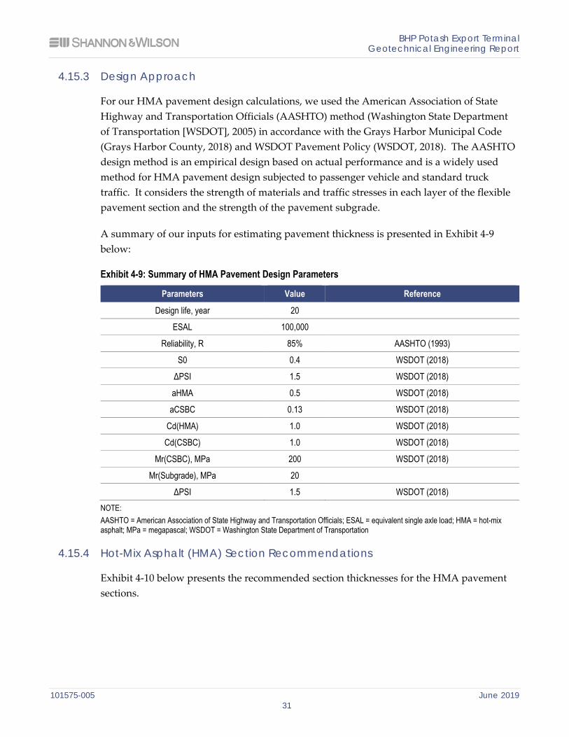
BHP Potash Export Terminal Geotechnical Engineering Report
101575-005 June 2019 31
4.15.3 Design Approach
For our HMA pavement design calculations, we used the American Association of State Highway and Transportation Officials (AASHTO) method (Washington State Department of Transportation [WSDOT], 2005) in accordance with the Grays Harbor Municipal Code (Grays Harbor County, 2018) and WSDOT Pavement Policy (WSDOT, 2018). The AASHTO design method is an empirical design based on actual performance and is a widely used method for HMA pavement design subjected to passenger vehicle and standard truck traffic. It considers the strength of materials and traffic stresses in each layer of the flexible pavement section and the strength of the pavement subgrade.
A summary of our inputs for estimating pavement thickness is presented in Exhibit 4-9 below:
Exhibit 4-9: Summary of HMA Pavement Design Parameters
Parameters Value Reference
Design life, year 20
ESAL 100,000
Reliability, R 85% AASHTO (1993)
S0 0.4 WSDOT (2018)
ΔPSI 1.5 WSDOT (2018)
aHMA 0.5 WSDOT (2018)
aCSBC 0.13 WSDOT (2018)
Cd(HMA) 1.0 WSDOT (2018)
Cd(CSBC) 1.0 WSDOT (2018)
Mr(CSBC), MPa 200 WSDOT (2018)
Mr(Subgrade), MPa 20
ΔPSI 1.5 WSDOT (2018) NOTE: AASHTO = American Association of State Highway and Transportation Officials; ESAL = equivalent single axle load; HMA = hot-mix asphalt; MPa = megapascal; WSDOT = Washington State Department of Transportation
4.15.4 Hot-Mix Asphalt (HMA) Section Recommendations
Exhibit 4-10 below presents the recommended section thicknesses for the HMA pavement sections.
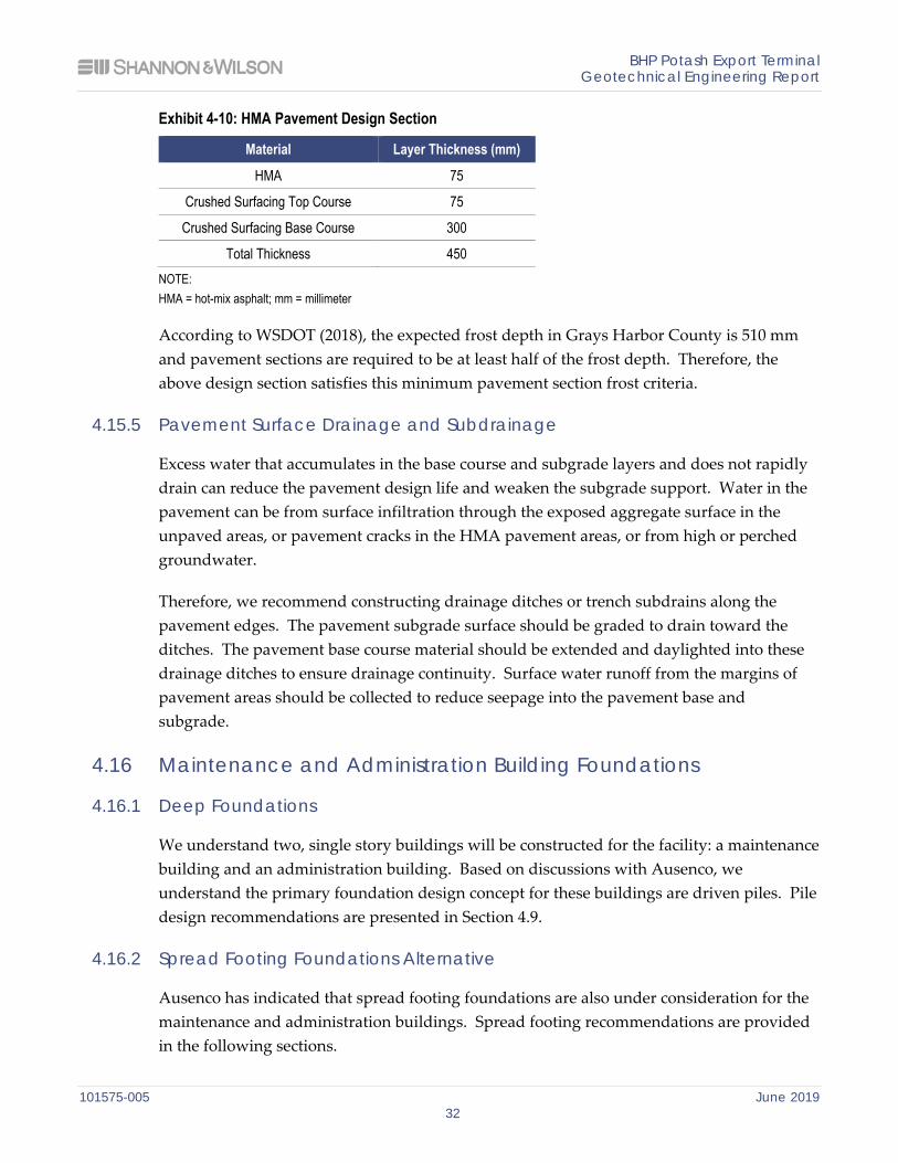
BHP Potash Export Terminal Geotechnical Engineering Report
101575-005 June 2019 32
Exhibit 4-10: HMA Pavement Design Section
Material Layer Thickness (mm)
HMA 75
Crushed Surfacing Top Course 75
Crushed Surfacing Base Course 300
Total Thickness 450 NOTE: HMA = hot-mix asphalt; mm = millimeter
According to WSDOT (2018), the expected frost depth in Grays Harbor County is 510 mm and pavement sections are required to be at least half of the frost depth. Therefore, the above design section satisfies this minimum pavement section frost criteria.
4.15.5 Pavement Surface Drainage and Subdrainage
Excess water that accumulates in the base course and subgrade layers and does not rapidly drain can reduce the pavement design life and weaken the subgrade support. Water in the pavement can be from surface infiltration through the exposed aggregate surface in the unpaved areas, or pavement cracks in the HMA pavement areas, or from high or perched groundwater.
Therefore, we recommend constructing drainage ditches or trench subdrains along the pavement edges. The pavement subgrade surface should be graded to drain toward the ditches. The pavement base course material should be extended and daylighted into these drainage ditches to ensure drainage continuity. Surface water runoff from the margins of pavement areas should be collected to reduce seepage into the pavement base and subgrade.
4.16 Maintenance and Administration Building Foundations
4.16.1 Deep Foundations
We understand two, single story buildings will be constructed for the facility: a maintenance building and an administration building. Based on discussions with Ausenco, we understand the primary foundation design concept for these buildings are driven piles. Pile design recommendations are presented in Section 4.9.
4.16.2 Spread Footing Foundations Alternative
Ausenco has indicated that spread footing foundations are also under consideration for the maintenance and administration buildings. Spread footing recommendations are provided in the following sections.
BHP Potash Export Terminal Geotechnical Engineering Report
101575-005 June 2019 33
4.16.2.1 Bearing Resistance and Anticipated Movement
We performed bearing resistance analyses for these structures and prepared charts of resistance versus footing width assuming square and strip shaped footprints as Figures 7 and 8, respectively. Bearing resistance for a footing depends on the size of the footing, the strength and compressibility of the foundation soil, the amount of settlement that the structure can tolerate, embedment depth, depth to groundwater, and resistance factors. For small footing widths, the strength of the foundation soil typically controls the allowable bearing pressure. Bearing pressure for larger footings is generally governed by tolerable settlement.
The bearing pressures provided in Figures 7 and 8 assume the footing bears on properly prepared subgrade material. Following excavation to obtain the desired footing grade, the exposed surface should be compacted to achieve a dense and unyielding condition. Areas that are wet, soft, loose, or yielding under the compaction process should be further compacted, removed and reconditioned, or replaced with compacted granular fill so that a dense and unyielding condition is achieved.
The settlement-limited bearing resistance curves included in Figures 7 and 8 are for static loading conditions. As discussed in Section 4.6, our liquefaction analyses indicate the existing fill material (ESU 0) below the groundwater table and alluvial sand deposits (ESU 2) will liquefy following the design earthquake ground motions. Our analyses suggest liquefaction-induced ground surface settlements could range from 100 to 600 mm in the upland area.
In addition to liquefaction-induced settlements, spread footings would also be subject to lateral spread deformations. As discussed in Section 4.7.4, our FLAC model results suggest lateral spread deformations in the upland area could be up to 7,000 mm toward the shoreline.
4.16.2.2 Resistance to Lateral Loads
Resistance to lateral movement for spread footings is derived from interface friction between the structure and underlying materials and passive pressure against the embedded vertical face of the footing.
We recommend evaluating sliding resistance using a nominal interface friction coefficient of 0.35. This is an unfactored value. For passive earth pressures, we recommend using a nominal equivalent fluid unit weight of 50 kN/m3 for static conditions and 45 kN/m3 for seismic conditions. These are unfactored values and assume the footing is backfilled with
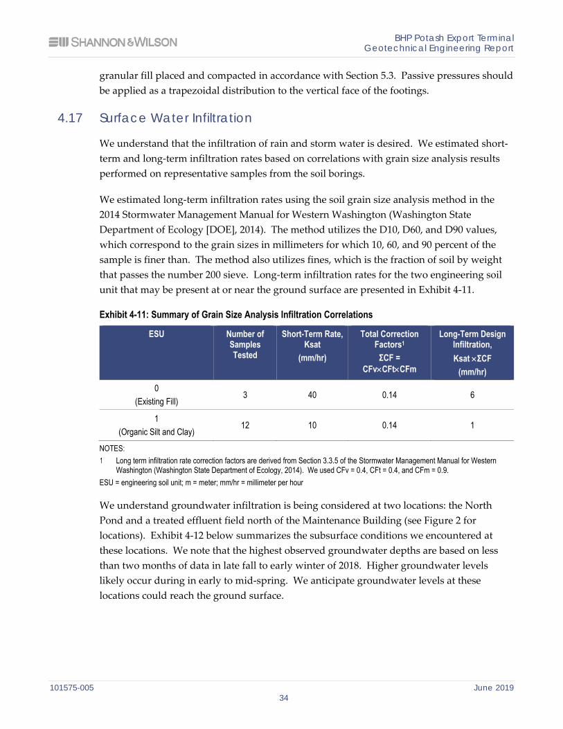
BHP Potash Export Terminal Geotechnical Engineering Report
101575-005 June 2019 34
granular fill placed and compacted in accordance with Section 5.3. Passive pressures should be applied as a trapezoidal distribution to the vertical face of the footings.
4.17 Surface Water Infiltration
We understand that the infiltration of rain and storm water is desired. We estimated short-term and long-term infiltration rates based on correlations with grain size analysis results performed on representative samples from the soil borings.
We estimated long-term infiltration rates using the soil grain size analysis method in the 2014 Stormwater Management Manual for Western Washington (Washington State Department of Ecology [DOE], 2014). The method utilizes the D10, D60, and D90 values, which correspond to the grain sizes in millimeters for which 10, 60, and 90 percent of the sample is finer than. The method also utilizes fines, which is the fraction of soil by weight that passes the number 200 sieve. Long-term infiltration rates for the two engineering soil unit that may be present at or near the ground surface are presented in Exhibit 4-11.
Exhibit 4-11: Summary of Grain Size Analysis Infiltration Correlations
ESU Number of Samples Tested
Short-Term Rate, Ksat
(mm/hr)
Total Correction Factors1
ΣCF = CFv×CFt×CFm
Long-Term Design Infiltration, Ksat ×ΣCF
(mm/hr) 0
(Existing Fill) 3 40 0.14 6
1 (Organic Silt and Clay)
12 10 0.14 1
NOTES: Long term infiltration rate correction factors are derived from Section 3.3.5 of the Stormwater Management Manual for Western
Washington (Washington State Department of Ecology, 2014). We used CFv = 0.4, CFt = 0.4, and CFm = 0.9. ESU = engineering soil unit; m = meter; mm/hr = millimeter per hour
We understand groundwater infiltration is being considered at two locations: the North Pond and a treated effluent field north of the Maintenance Building (see Figure 2 for locations). Exhibit 4-12 below summarizes the subsurface conditions we encountered at these locations. We note that the highest observed groundwater depths are based on less than two months of data in late fall to early winter of 2018. Higher groundwater levels likely occur during in early to mid-spring. We anticipate groundwater levels at these locations could reach the ground surface.
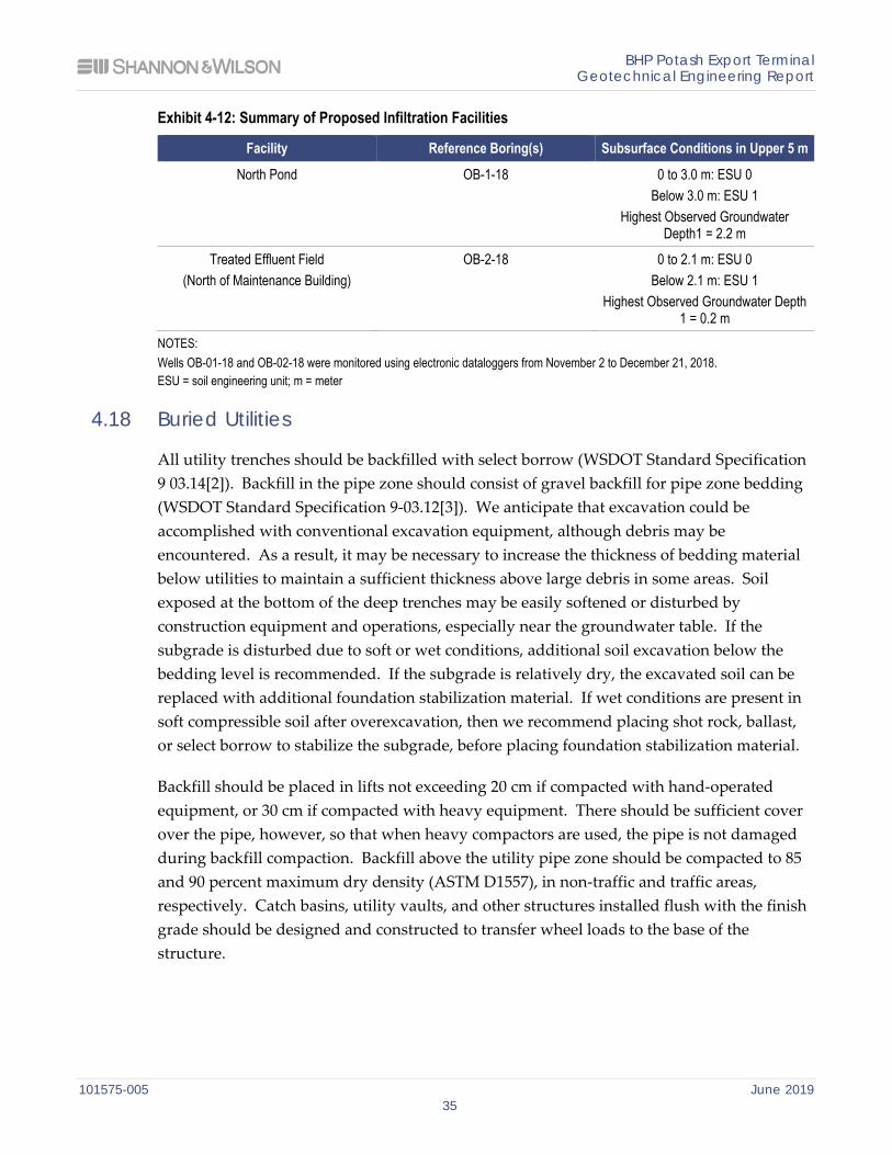
BHP Potash Export Terminal Geotechnical Engineering Report
101575-005 June 2019 35
Exhibit 4-12: Summary of Proposed Infiltration Facilities
Facility Reference Boring(s) Subsurface Conditions in Upper 5 m
North Pond OB-1-18 0 to 3.0 m: ESU 0 Below 3.0 m: ESU 1
Highest Observed Groundwater Depth1 = 2.2 m
Treated Effluent Field (North of Maintenance Building)
OB-2-18
0 to 2.1 m: ESU 0 Below 2.1 m: ESU 1
Highest Observed Groundwater Depth 1 = 0.2 m
NOTES: Wells OB-01-18 and OB-02-18 were monitored using electronic dataloggers from November 2 to December 21, 2018. ESU = soil engineering unit; m = meter
4.18 Buried Utilities
All utility trenches should be backfilled with select borrow (WSDOT Standard Specification 9 03.14[2]). Backfill in the pipe zone should consist of gravel backfill for pipe zone bedding (WSDOT Standard Specification 9-03.12[3]). We anticipate that excavation could be accomplished with conventional excavation equipment, although debris may be encountered. As a result, it may be necessary to increase the thickness of bedding material below utilities to maintain a sufficient thickness above large debris in some areas. Soil exposed at the bottom of the deep trenches may be easily softened or disturbed by construction equipment and operations, especially near the groundwater table. If the subgrade is disturbed due to soft or wet conditions, additional soil excavation below the bedding level is recommended. If the subgrade is relatively dry, the excavated soil can be replaced with additional foundation stabilization material. If wet conditions are present in soft compressible soil after overexcavation, then we recommend placing shot rock, ballast, or select borrow to stabilize the subgrade, before placing foundation stabilization material.
Backfill should be placed in lifts not exceeding 20 cm if compacted with hand-operated equipment, or 30 cm if compacted with heavy equipment. There should be sufficient cover over the pipe, however, so that when heavy compactors are used, the pipe is not damaged during backfill compaction. Backfill above the utility pipe zone should be compacted to 85 and 90 percent maximum dry density (ASTM D1557), in non-traffic and traffic areas, respectively. Catch basins, utility vaults, and other structures installed flush with the finish grade should be designed and constructed to transfer wheel loads to the base of the structure.
BHP Potash Export Terminal Geotechnical Engineering Report
101575-005 June 2019 36
5 CONSTRUCTION CONSIDERATIONS 5.1 Driven Pile Installation
The following sections present construction recommendations for driven pipe pile installation.
5.1.1 Pile-driving Conditions
Piles supporting the structures will be installed through the existing fill and the underlying soft silt and sand deposits into the very dense sand and gravel deposits. Potential obstructions, such as wood and occasional concrete debris and very dense, gravelly material, may be encountered during the installation of the piles through the upper fill material encountered from the ground surface to about 3 to 5 m deep. Remedial measures such as pre-drilling and pre-excavation may be required to mitigate the impact of the potential obstructions.
5.1.2 Pile-driving Equipment
All pile-driving equipment should be designed, constructed, and maintained in a manner suitable for the work to be accomplished for this project.
The piles may be initially be driven with an either impact, hydraulic, or a vibratory hammer to the top of the medium dense sand alluvium (ESU 2). Once in that layer, we assume the piles will be driven to the required penetration using a diesel or hydraulic impact hammer.
5.1.3 Preliminary Pile Driving Criteria
To improve tip bearing resistance for the closed-end piles, we recommend driving the piles a minimum of 2 pile diameters into the dense gravel layer (ESU 5). For open-ended piles, we recommend a minimum pile penetration of 5 pile diameters into the gravel. The top of the dense gravel layer (ESU 5) varies between about -43-m elevation to about -48 m (see Figures 3 through 5). For the 600- to 762-mm-diameter closed-end piles, we anticipate that the piles would be driven to continuous pile-driving blow count of at least 100 blows per 0.3 m and the minimum gravel penetration above. These pile-driving blow counts assume the piles were driven with an impact hammer similar to a Delmag/APE D-62 diesel pile-driving hammer.
For the 600-, 762-, 1,062-, and 1,219-mm-diameter open-end piles, we anticipate that the piles would be driven to continuous pile-driving blow count of between 30 to 60 blows per 0.3 m and the minimum gravel penetration above. These pile-driving blow counts assume the piles were driven with an impact hammer similar to a Delmag/APE D-62 diesel
BHP Potash Export Terminal Geotechnical Engineering Report
101575-005 June 2019 37
pile-driving hammer. For increased pile installation of the larger diameter piles, a larger impact hammer, such as a Delmag/APE D-80 may also be practical to use at a reduced fuel setting. We note that the relatively lightly loaded mooring dolphin piles may be able to be installed with a vibratory hammer and proofed with an impact hammer.
The actual depth of pile penetration achieved will vary depending upon the consistency and relative density of the soil encountered during pile driving. The recommended penetration into the dense sand and gravel and the driving resistance criteria may be modified after the initial production piles are driven and the pile driving analyzer (PDA) measurements and Case Pile Wave Analysis Program (CAPWAP) analyses are performed.
The criteria presented above are preliminary for use in the SPS phase study based on assumed hammers and pile configurations. If the piles and hammer sizes listed above are not selected for construction, we recommend that pile driving criteria be reevaluated utilizing data for the actual hammer/pile combination to be used to install the production piles.
5.1.4 Pile-driving Monitoring
Pile-driving should be monitored by taking a continuous driving record of each pile. For this purpose, the pile would be marked in 30-cm increments to facilitate monitoring. During restrikes and as the pile reaches the desired tip elevation, additional 1-inch increments between the 1-foot marks would be required.
The pile-driving record should be complete. The form should have spaces to record hammer stroke (diesel hammers), blows per foot, time, date, reasons for delays, and other pertinent information. In addition, the record should include tip elevation, specified criteria, and initials of inspectors making final acceptance of the pile.
It is often difficult to estimate the energy delivered by diesel hammers with visual observation. The Saximeter, developed by Pile Dynamics, Inc. (2010), can be used to record hammer strokes and provide an estimate of the driving energy of diesel hammers. We understand that the Contractor has selected a diesel hammer and, therefore, we recommend that a Saximeter be used during pile driving.
5.1.5 Potential Obstructions
The proposed piles may encounter wood and occasional concrete debris in the upper materials (ESU 0 and 1) encountered at the project site. If refusal conditions are encountered, the pile would be extracted, repaired if necessary, the pile location excavated
BHP Potash Export Terminal Geotechnical Engineering Report
101575-005 June 2019 38
to remove the obstruction, and the pile re-driven. Obstructions may be excavated with a drill or an excavator as the pile driving proceeds through this layer.
5.1.6 Pile Dynamic Testing
The recommendations for pile foundations and, in particular, the recommendations for pile penetrations and resistance are based on theoretical and empirical data, subsurface conditions encountered at the site, and our engineering experience. We recommend that dynamic measurements, using a PDA, be taken, and CAPWAP be performed on each tested pile. The PDA measurements should be taken at the end of initial driving and during re-strike. Restrike of the tested pile should occur a minimum of seven days after the end of initial driving.
5.2 Temporary Excavations
Construction slope angles required for stability and safety depend on careful evaluation of factors that include:
1. Contractor means and methods,
2. Amount and depth of groundwater seepage,
3. Soil and materials exposed in the excavation slope,
4. Depth of the excavation,
5. Surcharge loads on top of the excavation,
6. Geometry of the excavation, and
7. Time of construction.
Because of the many factors involved, required slope values can only be estimated prior to construction. For safe working conditions and prevention of ground loss, excavation slopes should be the responsibility of the Contractor, as they will be at the job site full time to observe and control the work. All current and applicable safety regulations regarding excavation slopes should be followed.
For planning purposes, we recommend assuming a Contractor would make temporary, unsupported, open-cut slopes in existing fill soil (ESU 0) no steeper than 1.5H:1V. The above recommendation is for temporary cut slopes in dry conditions. If wet conditions or groundwater inflow is encountered, flatter slopes may be required. Cuts extending into the underlying soft organic silt and clay (ESU 1) would likely require temporary shoring as described below. Exposed cut slopes may need to be protected with a waterproof covering during periods of wet weather to reduce sloughing and erosion. Cuts extending into the
BHP Potash Export Terminal Geotechnical Engineering Report
101575-005 June 2019 39
underlying soft, organic silt and clay (ESU 1) would likely require temporary shoring as described below.
Unshored, open-trench techniques might be suitable where the excavation depth is shallow and the trench sides can be sloped sufficiently to avoid trench side failure. Where the excavation depth exceeds 1.2 m, trench side sloping, trench boxes, a trench shoring system, or a combination of the above will be required. All traffic and/or construction equipment loads should be set back from the edge of the cut slopes a minimum of 1.2 m. Excavated material, stockpiles, and equipment should not be placed closer to the edge of any excavation than the depth of the excavation, unless the excavation is shored and such materials are accounted for as a surcharge load on the shoring system.
Based on expected temporary excavation depths of up to 1.8 m, anticipated subsurface conditions, and space limitations along the proposed alignment, we anticipate that trench excavations could be made using conventional excavating equipment, such as rubber-tired backhoes or tracked hydraulic excavators. If the exposed subgrade is too loose to provide a working surface or a firm foundation for utilities, the subgrade should be improved by compacting at least the upper 30 cm of loose, granular subgrade to a dense and unyielding condition.
5.3 Fill Placement and Compaction
Construction of the proposed project features will require placement and compaction of:
Embankment fill
Utility trench backfill
Retaining wall backfill
In our analyses, we assumed the embankment fill and utility trench backfill will be Common Borrow as specified in Section 9-03.14(3) of the WSDOT Standard Specification (WSDOT, 2016), with the exception that the material shall not contain more than 1 percent organic material by dry unit weight.
If fill is to be placed during periods of wet weather or under wet conditions, it should have the added requirement that the percentage of fines (materials passing the No. 200 sieve based on wet-sieving the minus 19 mm fraction) be limited to 5 percent. The fines should be non-plastic. Low permeability levee fill, which requires a minimum of 25 percent fines, should not be installed during periods of wet weather or under wet conditions. See Section 5.4 for additional wet weather construction considerations.
BHP Potash Export Terminal Geotechnical Engineering Report
101575-005 June 2019 40
Embankment fill, utility trench backfill, retaining wall backfill, and pipe zone bedding should be placed in horizontal uniform lifts and compacted to a dense and unyielding condition to at least 95 percent of the Modified Proctor maximum dry density (ASTM D1557) in accordance with Standard Specification Section 2-03.3(14)C, Method C (WSDOT, 2016). As required by WSDOT Standard Specification Section 2-03.3(14)C, Method C (WSDOT, 2016), the lift thickness should not exceed 46 cm. The appropriate lift thickness and compaction methods necessary to achieve this compaction criteria should be determined by the Contractor using the Contractor’s selected equipment and fill material. In situ soil density of all compacted fill materials must be verified with in situ soil density testing (nuclear gauge methods) in accordance with WSDOT Standard Specification 2-03.3(14)D (WSDOT, 2016).
5.4 Wet Weather Considerations
Most of the soil at the site likely contains sufficient fines to produce an unstable mixture when wet. Such soil is highly susceptible to changes in water content and tends to become unstable and difficult or impossible to proof roll and compact if the moisture content significantly exceeds the optimum. In addition, during wet weather months, the groundwater levels could increase, resulting in seepage into site excavations. Performing earthwork during dry weather would reduce these problems and costs associated with rainwater, trafficability, and handling of wet soil.
Based on our understanding of the construction schedule, rainy periods will generally occur during construction. As a result, we highly recommend that the Contractor review the following considerations to reduce the potential for more difficult earthwork operations during wet weather:
The ground surface in and surrounding the construction area should be sloped as much as possible and sealed with a smooth-drum roller to promote runoff of precipitation away from work areas and to prevent ponding of water.
Work areas or slopes should be covered with plastic. The use of sloping, ditching, sumps, dewatering, and other measures should be employed as necessary to permit proper completion of the work.
If there is to be traffic over the exposed subgrade, the subgrade should be protected from disturbance.
Earthwork should be accomplished in small sections to minimize exposure to wet conditions. That is, each section should be small enough so that the removal of unsuitable soil and placement and compaction of clean structural fill could be accomplished on the same day. The size of construction equipment may have to be limited to prevent soil disturbance. It may be necessary to excavate soil with a backhoe,
BHP Potash Export Terminal Geotechnical Engineering Report
101575-005 June 2019 41
or equivalent, and locate the equipment so that it does not pass over the excavated area. Thus, subgrade disturbance caused by equipment traffic would be minimized.
Fill material should consist of clean, well-graded, pit-run sand and gravel soil, of which not more than 5 percent fines by dry weight passes the No. 200 mesh sieve, based on wet sieving the fraction passing the 19-mm mesh sieve. The fines should be nonplastic.
No soil should be left uncompacted and exposed to moisture. A smooth-drum vibratory roller, or equivalent, should roll the surface to seal out as much water as possible. Because of the soft subgrades likely present at the site, use of a static roller may be necessary.
In-place soil or fill soil that becomes wet and unstable and/or too wet to suitably compact should be removed and replaced with clean, granular soil (see gradation requirements above).
Grading and earthwork should not be accomplished during periods of heavy, continuous rainfall.
The above recommendations apply for all weather conditions but are most important for wet weather earthwork.
5.5 Settlement Monitoring and Instrumentation
Settlement monitoring should be considered for the following:
Potash storage building – before, during, and after potash stockpiling;
Overpass bridge approach embankments – before, during, and after construction;
Railroad embankment through the pond – before, during, and after construction; and
Existing dike near the proposed railroad loop – before, during, and after construction of the nearby railroad embankment.
Settlement data collected before construction or before stockpiling will be used to establish a baseline for subsequent observations. Settlement data collected during and after construction or stockpiling will be used to check assumptions implemented within our settlement analyses, to evaluate possible settlement-related issues that could develop with proposed project elements, and to determine when settlement is substantially complete.
Settlement monitoring during construction can be used to help decide when to install structural elements such as pavement for the overpass bridge approaches or the track structure for the railroad embankment. The client may need to balance possible construction delays against the potential for future maintenance issues.
BHP Potash Export Terminal Geotechnical Engineering Report
101575-005 June 2019 42
5.6 Construction Observation
We cannot assume responsibility or liability for the adequacy of our recommendations without our being retained to observe geotechnical construction activities. Our involvement will help with developing alternative recommendations if the conditions observed during construction are different from those assumed in this report. Our support services should include review of the Contractor’s geotechnical submittals; observation of foundation installation and excavations; and as-needed support to clarify related issues.
6 SUMMARY OF RECOMMENDATIONS AND RECOMMENDED FUTURE STUDY This section summarizes the SPS phase geotechnical design recommendations for the primary elements of the Grays Harbor Potash Export Terminal. We evaluated multiple alternative engineering solutions for each project element and discussed them with Ausenco and BHP. Based on these discussions and the available subsurface information, preferred alternatives were selected and carried forward into the SPS design concept. This section summarizes those preferred alternatives and highlights aspects that may require additional study for final design.
6.1 Design Ground Motions
The design ground motions we used in our analyses are based on the 2,475-year return period maximum credible earthquake (MCE) per ASCE 61-14 and ASCE 7-05 for marine structures. Depending on the development schedule of the project, design spectra and ground motions may have to be updated for the latest ASCE 7 codes.
We developed a suite of three ground motions for our evaluations thus requiring the maximum response for any of those ground motions to be considered for design. It would likely be beneficial to the project to develop a large suite of 7 or 11 ground motions (depending on future code adoption) so that a likely lower mean response need only be considered.
Based on BHP’s operational requirements, risk tolerances, and the particular structures being considered, it may be important and/or beneficial to the project to consider smaller, service level design motions in addition to or in lieu of the 2,475-year MCE. For example, WSDOT requires non-essential bridges be designed for 1,033-year return period ground motions. Therefore, there may be some potential to reduce the seismic demands for the overpass structure and approach fill walls.
BHP Potash Export Terminal Geotechnical Engineering Report
101575-005 June 2019 43
6.2 Storage Building and Product Support Slab
The storage building structure will be supported by open-ended steel pipe piles driven at least 5 pile diameters into dense gravel layer below about elevation -43 m.
The product support slab will be supported by closed-ended steel pipe piles driven at least 2 pile diameters into the dense gravel layer (ESU 5). We estimate the product support slab will settle approximately 25 mm under the weight of the full potash stockpile load. These estimates were based on a factor of safety of 1.25 for vertical capacity that is lower than the typical value of 2.0 used in most designs. The lower factor of safety carries with it a risk of exceeding the settlement estimates. Additional studies should be performed to evaluate the potential for excess settlements and the impact on the facilities operation.
If product support slab settlement criteria can be increased, other product support options may be more economical. An economic and facility performance tradeoff study should be performed for final design considering the other options presented.
Additional explorations will be necessary in the storage building footprint, including the wetland areas within the storage building footprint that were not accessible for the SPS phase.
6.3 Railcar Dumper Pit (RDP) Structure
The RDP structure will be constructed using a vertical excavation supported by secant piling and internal strut bracing. This option may require the base of the excavation be ground improved for lateral, uplift, and/or groundwater control purposes. Temporary dewatering wells within the excavation may also be necessary to mitigate uplift /base heave instability during construction depending on construction methods. We recommend that a contractor be engaged to evaluate the benefits of various RDP construction methods that could be used..
6.4 Transfer Towers and Conveyor Bents
Open-ended steel pipe piles driven at least 5 pile diameters into dense gravel (ESU 5) are recommended to support the transfer towers and conveyor bents.
Use of shallow foundations could be considered in more detail in final design. However, due to strength loss from liquefaction, consolidation of liquefiable soils, co-seismic lateral displacements, lateral spreading, and highly compressible estuarine silts, this would require the superstructure to be designed to withstand significant vertical and lateral total and differential deformations.
BHP Potash Export Terminal Geotechnical Engineering Report
101575-005 June 2019 44
6.5 Marine Facility
Open-ended steel pipe piles driven at least 5 pile diameters into dense gravel (ESU 5) are recommended to support the marine facility structures. Additional studies of the marine facility should include the service level performance of the facility during lower ground motions levels as it is expected that lateral spreading in a lesser magnitude will still likely occur.
6.6 Marine Slopes
Dredging is required at the marine facility for ship berthing. For a FS against marine slope instability of 1.3 or higher, the dredged cut slope should be no steeper than 3.75H:1V. We understand this would cause some intertidal area to be removed, which increases the complexity of environmental permitting. We recommend a seawall (i.e., submarine sheet piles or similar) option be considered in the next phase of design.
6.7 Overpass Structure
Open-ended steel pipe piles driven at least 5 pile diameters into the dense gravel (ESU 5) are recommended to support the overpass bridge piers.
The SPS design configuration for the approach embankment assumes the approach fill will be retained by vertical wing walls within 25 m of the piers. We recommend lightweight fill (i.e., geofoam or geosynthetic reinforced cellular concrete) be used to construct these walls. Use of lightweight fill would mitigate global instability of the walls and excessive settlement. Mitigation of settlement would allow the bridge piles to be designed without static downdrag and would improve drivability and long-term maintenance requirements that would arise if the approach fill settled significantly more than the bridge piers.
6.8 Maintenance and Administrative Buildings
The preferred foundation alternative for the maintenance and administration buildings are steel pipe piles driven at least 5 pile diameters into dense gravel (ESU 5). However, spread footings foundations may also be feasible if the structure can be designed to tolerate (a) long-term static settlement, (b) liquefaction-induced settlements, and (c) seismic-induced lateral spread movement.
6.9 New Rail Loop
A significant portion of the rail loop is proposed within wetland areas or wetland buffers (see Figure 2). Due to permitting restrictions during the exploration phase, we were unable to access wetland areas or wetland buffers to perform subsurface explorations. We
BHP Potash Export Terminal Geotechnical Engineering Report
101575-005 June 2019 45
anticipate soft near-surface soil to be present in these areas. We developed one track bed structure configuration for the entire rail loop assuming very soft conditions. We recommend a minimum subballast thickness of 305 mm and a ballast thickness of 1,160 mm measured at the track center from bottom of tie.
We recommend performing explorations in the wetland areas of the track alignment to characterize the track subgrade conditions for final design. Doing this in addition to dividing the track alignment into different design segments may allow a more economical track bed structure design to be developed.
A portion of the proposed rail loop is adjacent to the City of Hoquiam sewage lagoon dike. To mitigate potential settlement of this existing dike to the west and instability toward the existing pond to the east, sheet piles are recommended to be installed on both sides of the proposed rail embankment in this area. For the SPS design concept, the western sheet piles along the existing dike are assumed to be driven down to the dense gravel layer (ESU 5). The sheet piles on the eastern side are only needed for global stability and only need to be driven about 15 m deep. We recommend a finite element soil structure interaction analysis be performed for final design to assess settlement of the existing dike. In addition, performing a tradeoff study considering the other two dike protection options presented in Section 4.14.2 be performed in the next phase of engineering.
6.10 Surface Water Treatment Facilities
Stormwater ponds and surface water infiltration facilities are proposed. Recommended infiltration rates for design are provided in Section 4.17. Areas of the site where the groundwater level is at or within a meter of the ground surface and where fine-grained soil (ESU 2) are present at the base of the pond may be unsuitable for infiltration because these factors diminish the ability of the subgrade to take in water. Infiltration in areas with unsaturated existing fill material (ESU 1) greater than a few meters deep may be feasible.
7 CLOSURE This geotechnical report presents the data from field explorations, and field and laboratory testing of subsurface conditions at the specific locations indicated, using the means and methods and building codes described in this report. No other representation is made. Subsurface conditions that are interpreted from the data included in this report may not be construed as a guarantee or warranty of such interpreted conditions.
The analyses, conclusions, and recommendations contained in this report are based on site conditions as they presently exist and the referenced building codes described herein. We
BHP Potash Export Terminal Geotechnical Engineering Report
101575-005 June 2019 46
assume that the subsurface conditions encountered in the explorations made for this project are representative of the subsurface conditions throughout the project area (i.e., the subsurface conditions everywhere are not significantly different from those disclosed by the boring). If conditions different from those described in this report are observed or appear to be present during construction, we should be advised at once so that we can review these conditions and reconsider our recommendations, where necessary. This report was prepared using the building codes noted in this report. If there is a substantial lapse of time between submission of our report and the application for a building permit, the referenced building codes described herein may have changed. This report may not be construed as a guarantee or warranty of the applicability of the building code other than at the time of the submission of our report.
If there is a substantial lapse of time between submission of our report and the start of work at the site, or if conditions have changed because of natural forces or construction operations at or near the site, it is recommended that this report be reviewed to check the applicability of the conclusions and recommendations considering the changed conditions and time lapse. Natural processes or human activity may alter subsurface conditions. Because a geotechnical report is based on conditions that existed at the time of subsurface explorations, construction decisions should not be based on a report whose adequacy may have been affected by time, unless verified. Unanticipated soil conditions are commonly encountered and cannot fully be determined by merely taking soil samples from borings.
Shannon & Wilson, Inc. has prepared the enclosed "Important Information About Your Geotechnical/ Environmental Report" to assist you and others in understanding the use and limitations of our reports.
8 REFERENCES American Railway Engineering and Maintenance-of-Way Association (AREMA), 2018,
Manual for railway engineering: Landover, Md., AREMA, 4 v.
Al Atik, Linda and Abrahamson, Norman, 2010, An improved method for nonstationary spectral matching: Earthquake Spectra, v. 26, no. 3, p. 601-617.
American Society of Civil Engineers (ASCE), 2006, Minimum design loads for buildings and other structures: Reston, Va. American Society of Civil Engineers, ASCE Standard ASCE/SEI 7-05.
BHP Potash Export Terminal Geotechnical Engineering Report
101575-005 June 2019 47
ARA, Inc., ERES Division (ARA), 2001, Correlation of CBR values with soil index properties, in Guide for mechanistic-empirical design of new and rehabilitated pavement structures: Washington, D.C., Transportation Research Board, NCHRP 1-37A, appendix CC-1.
Ausenco Engineering, Inc. (Ausenco), 2017, Jansen Outbound Logistics Identification Phase, Grays Harbor, General Arrangement, Preliminary – Not for Construction, March 10, drawing no. 101051-03-G-SK-30, 1 sheet, scale 1:3000.
BergerABAM, 2018, Proposed Grays Harbor potash export facility – terminal 3 groundwater monitoring wells: well coordinates and groundwater elevations: Memorandum from V. England, BergerABAM, Vancouver, Wash., to M. Sweeney, Ausenco Limited, October 30.
Boulanger, R. W. and Ziotopoulou, K., 2017, PM4Sand (v. 3.1): a sand plasticity model for earthquake engineering applications: Davis, Calif., University of California, Center for Geotechnical Modeling, Report no. UCD/CGM-17/01, 114 p., March.
Boulanger, R. W. and Idriss, I. M., 2014, CPT and SPT-based liquefaction triggering procedures: Davis, Calif., University of California Davis, Center for Geotechnical Modeling, report UCD/CGM-14/01, 134 p.
Electric Power Research Institute, 1993, Guidelines for determining design basis ground motions: Palo Alto, Calif., Electric Power Research Institute, Report no. TR-102293, 5 v.
Grays Harbor County, 2018, A Codification of the General Ordinances of the County of Grays Harbor, Washington, available: https://library.municode.com/wa/grays_harbor_county/codes/code_of_ordinances?nodeId=GRAYS_HARBOR_CO_WASHINGTONMUCO
Huang, Y. H., 1993, Pavement analysis and design: Englewood Cliffs, N.J., Prentice Hall, 805 p.
International Code Council, Inc., 2014, International building code 2015: Country Club Hills, Ill., International Code Council, Inc., 700 p.
Ordonez, G. O., 2011, SHAKE2000, v. 8.5.0: Lacey, Wash., GeoMotions, LLC.
Pile Dynamics, Inc., 2010, GRLWEAP, one-dimensional wave equation analysis: Cleveland, Ohio, Pile Dynamics, Inc.
BHP Potash Export Terminal Geotechnical Engineering Report
101575-005 June 2019 48
Roger Lowe Associates, Inc., 1979-1980, Figures, boring logs, and laboratory test results from geotechnical reports for ITT Rayonier: Excerpts dated September 6, 1979 and January 25, 1980, 50 p., received by Shannon & Wilson, Inc. from Ausenco August 16, 2017.
Rollins, K. M.; Evans, M. D.; Diehl, N. B.; and Daily, W. D., III, 1998, Shear modulus and damping relationships for gravels: Journal of Geotechnical and Geoenvironmental Engineering, v. 124, no. 5, p. 396-405.
Schnabel, P. B.; Lysmer, John; and Seed, H. B., 1972, SHAKE, a computer program for earthquake analysis of horizontally layer sites: Berkeley, Calif., University of California, Report no. EERC 72-12, 46 p.
Shannon & Wilson, Inc., 2008, Geotechnical report, wastewater treatment facility biosolids lagoon project, Hoquiam, Washington: Report prepared by Shannon & Wilson, Inc., Seattle, Wash., 21-1-21000-001, for HDR Engineering, Inc., December.
Shannon & Wilson, Inc., 2013, Draft geotechnical report, USD crude-by-rail terminal, Port of Grays Harbor, Hoquiam, Washington: Report prepared by Shannon & Wilson, Inc., Seattle, Wash., 21-1-21839-001, for HDR Engineering, Inc., September.
Shannon & Wilson, Inc., 2019, Geotechnical data report, BHP Potash Export Terminal, Hoquiam, Washington: Report prepared by Shannon & Wilson, Inc., Seattle, Wash., 101575-004, for Ausenco Engineering Canada, Inc., March.
Vucetic, Mladen and Dobry, Ricardo, 1991, Effect of soil plasticity on cyclic response: Journal of Geotechnical Engineering, v. 117, no. 1, p. 89-107.
Washington State Department of Ecology (DOE), 2014, Stormwater management manual for western Washington: Olympia, Wash., Washington State Department of Ecology Publication no. 14-10-055, 5 v.
Washington State Department of Transportation (WSDOT), 2005, Everseries user’s guide -pavement analysis computer software and case studies: Olympia, Wash., WSDOT Materials Laboratory, 112 p., available: http://www.wsdot.wa.gov/NR/rdonlyres/0C02BB7B-C345-4958-AA08-089E5E512B96/0/EverseriesUserGuidePart1.pdf.
Washington Department of Transportation (WSDOT), 2016, Standard specifications for road, bridge, and municipal construction: Olympia, Wash., WSDOT, Manual M 41-10, 1 v., January, available: http://www.wsdot.wa.gov/Publications/Manuals/M41-10.htm.

BHP Potash Export Terminal Geotechnical Engineering Report
101575-005 June 2019 49
Washington State Department of Transportation (WSDOT), 2018, WSDOT pavement policy: Olympia, Wash., WSDOT, 131 p., available: http://www.wsdot.wa.gov/Business/MaterialsLab/Pavements/Defa ult.htm.


![[Institute for Career Research] Careers in Enginee(BookZZ.org)](https://img.pdfslide.us/doc/110x75/56d6c04b1a28ab301699c89e/institute-for-career-research-careers-in-engineebookzzorg.jpg)