Embed Size (px)
Citation preview
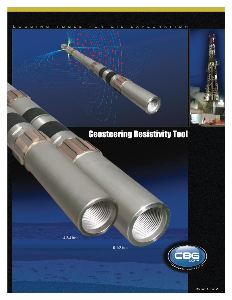
Geosteering Resistivity Tool
L o g g i n g t o o l s f o r o i l e x p l o r a t i o n
4-3/4 inch
6-1/2 inch
Page 1 of 6Page 1 of 6
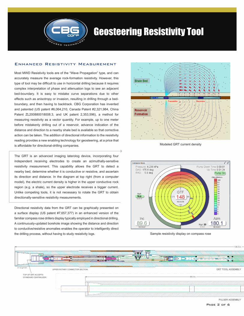
Enhanced Resistivity Measurement
Most MWD Resistivity tools are of the “Wave Propagation” type, and can accurately measure the average rock-formation resistivity. However, this type of tool may be difficult to use in horizontal drilling because it requires complex interpretation of phase and attenuation logs to see an adjacent bed-boundary. It is easy to mistake curve separations due to other effects such as anisotropy or invasion, resulting in drilling through a bed-boundary, and then having to backtrack. CBG Corporation has invented and patented (US patent #6,064,210, Canada Patent #2,321,984, China Patent ZL200880018008.3, and UK patent 2,353,596), a method for measuring resistivity as a vector quantity. For example, up to one meter before mistakenly drilling out of a reservoir, advance indication of the distance and direction to a nearby shale bed is available so that corrective action can be taken. The addition of directional information to the resistivity reading provides a new enabling technology for geosteering, at a price that is affordable for directional-drilling companies.
The GRT is an advanced imaging laterolog device, incorporating four independent receiving electrodes to create an azimuthally-sensitive resistivity measurement. This capability allows the GRT to detect a nearby bed, determine whether it is conductive or resistive, and ascertain its direction and distance. In the diagram at top right (from a computer model), the electric current density is higher in the upper conductive rock region (e.g. a shale), so the upper electrode receives a bigger current. Unlike competing tools, it is not necessary to rotate the GRT to obtain directionally-sensitive resistivity measurements.
Directional resistivity data from the GRT can be graphically presented on a surface display (US patent #7,657,377) in an enhanced version of the familiar compass rose drillers display typically employed in directional drilling. A continuously-updated borehole image showing the distance and direction to conductive/resistive anomalies enables the operator to intelligently direct the drilling process, without having to study resistivity logs.
Geosteering Resistivity Tool
Sample resistivity display on compass rose
Modeled GRT current density
Page 2 of 6
Advanced Cost-Effective Design
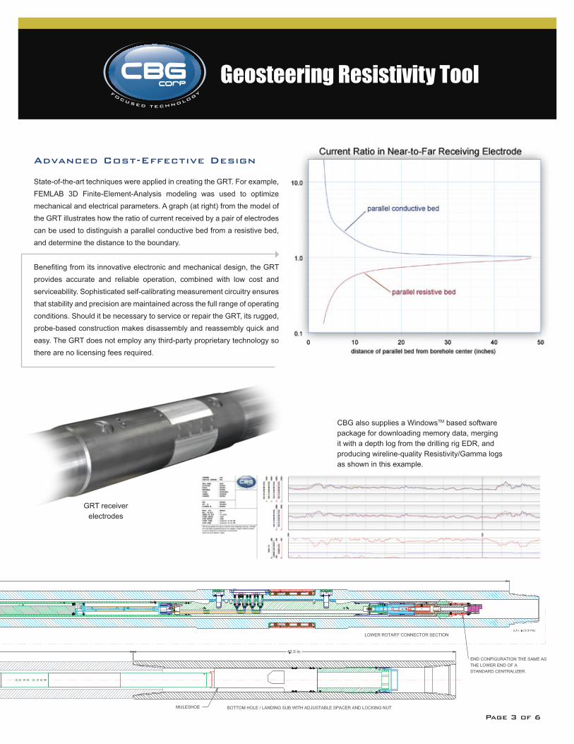
State-of-the-art techniques were applied in creating the GRT. For example, FEMLAB 3D Finite-Element-Analysis modeling was used to optimize mechanical and electrical parameters. A graph (at right) from the model of the GRT illustrates how the ratio of current received by a pair of electrodes can be used to distinguish a parallel conductive bed from a resistive bed, and determine the distance to the boundary.
Benefiting from its innovative electronic and mechanical design, the GRT provides accurate and reliable operation, combined with low cost and serviceability. Sophisticated self-calibrating measurement circuitry ensures that stability and precision are maintained across the full range of operating conditions. Should it be necessary to service or repair the GRT, its rugged, probe-based construction makes disassembly and reassembly quick and easy. The GRT does not employ any third-party proprietary technology so there are no licensing fees required.
GRT receiver electrodes
CBG also supplies a WindowsTM based software package for downloading memory data, merging it with a depth log from the drilling rig EDR, and producing wireline-quality Resistivity/Gamma logs as shown in this example.
Geosteering Resistivity Tool
Page 3 of 6
Logging While Drilling
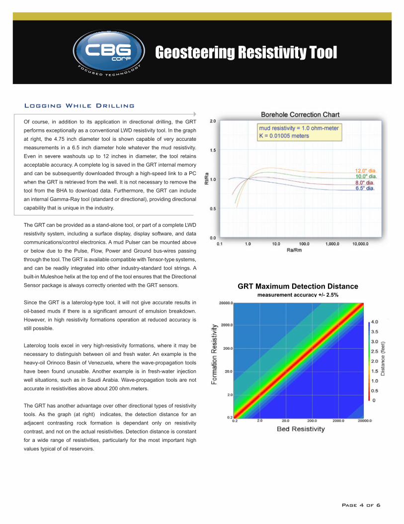
Of course, in addition to its application in directional drilling, the GRT performs exceptionally as a conventional LWD resistivity tool. In the graph at right, the 4.75 inch diameter tool is shown capable of very accurate measurements in a 6.5 inch diameter hole whatever the mud resistivity. Even in severe washouts up to 12 inches in diameter, the tool retains acceptable accuracy. A complete log is saved in the GRT internal memory and can be subsequently downloaded through a high-speed link to a PC when the GRT is retrieved from the well. It is not necessary to remove the tool from the BHA to download data. Furthermore, the GRT can include an internal Gamma-Ray tool (standard or directional), providing directional capability that is unique in the industry.
The GRT can be provided as a stand-alone tool, or part of a complete LWD resistivity system, including a surface display, display software, and data communications/control electronics. A mud Pulser can be mounted above or below due to the Pulse, Flow, Power and Ground bus-wires passing through the tool. The GRT is available compatible with Tensor-type systems, and can be readily integrated into other industry-standard tool strings. A built-in Muleshoe helix at the top end of the tool ensures that the Directional Sensor package is always correctly oriented with the GRT sensors.
Since the GRT is a laterolog-type tool, it will not give accurate results in oil-based muds if there is a significant amount of emulsion breakdown. However, in high resistivity formations operation at reduced accuracy is still possible.
Laterolog tools excel in very high-resistivity formations, where it may be necessary to distinguish between oil and fresh water. An example is the heavy-oil Orinoco Basin of Venezuela, where the wave-propagation tools have been found unusable. Another example is in fresh-water injection well situations, such as in Saudi Arabia. Wave-propagation tools are not accurate in resistivities above about 200 ohm.meters.
The GRT has another advantage over other directional types of resistivity tools. As the graph (at right) indicates, the detection distance for an adjacent contrasting rock formation is dependant only on resistivity contrast, and not on the actual resistivities. Detection distance is constant for a wide range of resistivities, particularly for the most important high values typical of oil reservoirs.
GRT Maximum Detection Distancemeasurement accuracy +/- 2.5%
form
atio
n r
esis
tivi
ty
bed resistivity
distance(inches)
20000 -
2000 -
200 -
20 -
2 -
0.2 -
0.2 2 20 200 2000 20000
- - - - - -
8 16 24 32 40 48
- - - - - -
Geosteering Resistivity Tool
Page 4 of 6
Geosteering Resistivity Tool
GRT Verifier Product Description
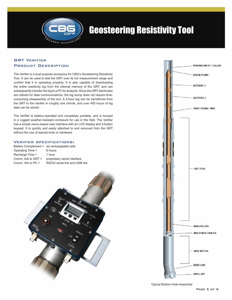
The Verifier is a dual purpose accessory for CBG’s Geosteering Resistivity Tool. It can be used to test the GRT over its full measurement range and confirm that it is operating properly. It is also capable of downloading the entire resistivity log from the internal memory of the GRT, and can subsequently transfer the log to a PC for analysis. Since the GRT electrodes are utilized for data communications, the log dump does not require time-consuming disassembly of the tool. A 3-hour log can be transferred from the GRT to the Verifier in roughly one minute, and over 400 hours of log data can be stored.
The Verifier is battery-operated and completely portable, and is housed in a rugged weather-resistant enclosure for use in the field. The Verifier has a simple menu-based user interface with an LCD display and 3-button keypad. It is quickly and easily attached to and removed from the GRT without the use of special tools or hardware.
Verifier specifications:Battery Complement = six rechargeable cellsOperating Time = 6 hours Recharge Time = 1 hourComm. link to GRT = proprietary serial interfaceComm. link to PC = RS232 serial link and USB link
Typical Bottom-Hole-AssemblyPage 5 of 6
4616 West Howard LaneSuite 900
Austin, Texas 78728
Tel: 512-491-7541Fax: 512-491-7561
w w w . c b g c o r p . c o m
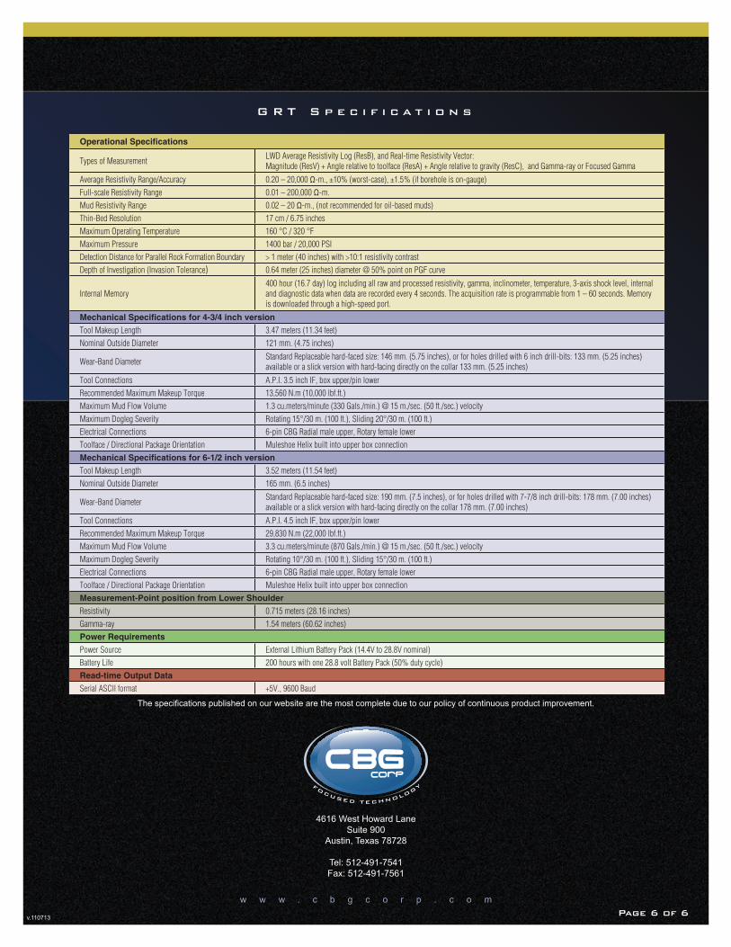
G R T S p e c i f i c a t i o n s
v.110713
The specifications published on our website are the most complete due to our policy of continuous product improvement.
Operational Specifications
Types of Measurement LWD Average Resistivity Log (ResB), and Real-time Resistivity Vector: Magnitude (ResV) + Angle relative to toolface (ResA) + Angle relative to gravity (ResC), and Gamma-ray or Focused Gamma
Average Resistivity Range/Accuracy 0.20 – 20,000 Ω-m., ±10% (worst-case), ±1.5% (if borehole is on-gauge)
Full-scale Resistivity Range 0.01 – 200,000 Ω-m.
Mud Resistivity Range 0.02 – 20 Ω-m., (not recommended for oil-based muds)
Thin-Bed Resolution 17 cm / 6.75 inches
Maximum Operating Temperature 160 °C / 320 °F
Maximum Pressure 1400 bar / 20,000 PSI
Detection Distance for Parallel Rock Formation Boundary > 1 meter (40 inches) with >10:1 resistivity contrast
Depth of Investigation (Invasion Tolerance) 0.64 meter (25 inches) diameter @ 50% point on PGF curve
Internal Memory400 hour (16.7 day) log including all raw and processed resistivity, gamma, inclinometer, temperature, 3-axis shock level, internal and diagnostic data when data are recorded every 4 seconds. The acquisition rate is programmable from 1 – 60 seconds. Memory is downloaded through a high-speed port.
Mechanical Specifications for 4-3/4 inch version
Tool Makeup Length 3.47 meters (11.34 feet)
Nominal Outside Diameter 121 mm. (4.75 inches)
Wear-Band DiameterStandard Replaceable hard-faced size: 146 mm. (5.75 inches), or for holes drilled with 6 inch drill-bits: 133 mm. (5.25 inches) available or a slick version with hard-facing directly on the collar 133 mm. (5.25 inches)
Tool Connections A.P.I. 3.5 inch IF, box upper/pin lower
Recommended Maximum Makeup Torque 13,560 N.m (10,000 lbf.ft.)
Maximum Mud Flow Volume 1.3 cu.meters/minute (330 Gals./min.) @ 15 m./sec. (50 ft./sec.) velocity
Maximum Dogleg Severity Rotating 15°/30 m. (100 ft.), Sliding 20°/30 m. (100 ft.)
Electrical Connections 6-pin CBG Radial male upper, Rotary female lower
Toolface / Directional Package Orientation Muleshoe Helix built into upper box connection
Mechanical Specifications for 6-1/2 inch version
Tool Makeup Length 3.52 meters (11.54 feet)
Nominal Outside Diameter 165 mm. (6.5 inches)
Wear-Band DiameterStandard Replaceable hard-faced size: 190 mm. (7.5 inches), or for holes drilled with 7-7/8 inch drill-bits: 178 mm. (7.00 inches) available or a slick version with hard-facing directly on the collar 178 mm. (7.00 inches)
Tool Connections A.P.I. 4.5 inch IF, box upper/pin lower
Recommended Maximum Makeup Torque 29,830 N.m (22,000 lbf.ft.)
Maximum Mud Flow Volume 3.3 cu.meters/minute (870 Gals./min.) @ 15 m./sec. (50 ft./sec.) velocity
Maximum Dogleg Severity Rotating 10°/30 m. (100 ft.), Sliding 15°/30 m. (100 ft.)
Electrical Connections 6-pin CBG Radial male upper, Rotary female lower
Toolface / Directional Package Orientation Muleshoe Helix built into upper box connection
Measurement-Point position from Lower Shoulder
Resistivity 0.715 meters (28.16 inches)
Gamma-ray 1.54 meters (60.62 inches)
Power Requirements
Power Source External Lithium Battery Pack (14.4V to 28.8V nominal)
Battery Life 200 hours with one 28.8 volt Battery Pack (50% duty cycle)
Read-time Output Data
Serial ASCII format +5V., 9600 Baud
Page 6 of 6Page 6 of 6