Embed Size (px)
Citation preview
HAL Id: hal-03309704https://hal.archives-ouvertes.fr/hal-03309704
Submitted on 30 Jul 2021
HAL is a multi-disciplinary open accessarchive for the deposit and dissemination of sci-entific research documents, whether they are pub-lished or not. The documents may come fromteaching and research institutions in France orabroad, or from public or private research centers.
L’archive ouverte pluridisciplinaire HAL, estdestinée au dépôt et à la diffusion de documentsscientifiques de niveau recherche, publiés ou non,émanant des établissements d’enseignement et derecherche français ou étrangers, des laboratoirespublics ou privés.
Geometry optimization of helical swimming at lowReynolds number
Johan Quispe, Ali Oulmas, Stéphane Régnier
To cite this version:Johan Quispe, Ali Oulmas, Stéphane Régnier. Geometry optimization of helical swimming at lowReynolds number. 2019 International Conference on Manipulation, Automation and Robotics at SmallScales (MARSS), Jul 2019, Helsinki, Finland. pp.1-6, 10.1109/MARSS.2019.8860937. hal-03309704
Geometry optimization of helical swimming at lowReynolds number
Johan E. Quispe, Ali Oulmas and Stephane RegnierInstitut des Systemes Intelligents et Robotique (ISIR)
Sorbonne UniversiteParis, France
[email protected]@isir.upmc.fr
Abstract—This paper aims to improve magnetic helical swim-ming varying the cross-section geometry and considering aconical geometry for helical robot. Both parameters have notbeen extensively studied in the literature. The conical helix isgenerated when the helix radial pitch varies constantly anddue to that, it could be used in delivery tasks of big-sizedmillimetric objects. To conceive the whole study, experimentation,and finite-element-method (FEM) simulations are performed inorder to corroborate the experimental data in the literature. Theinfluence on the propulsion of the helix cross-section geometryin a cylindrical helix, and the number of turns in a conicalhelix was demonstrated. Results show that helices with triangularcross-sections provide better propulsion than circular ones, theselatter widely used in various micro- and nanoswimmer designs inliterature. This result could change the way that helical swimmersare manufactured today. Besides, conical helices with 1-turn and1.5-turn have shown better performances than multi-turn onesin terms of speed and propulsion force. From this part of thestudy, the main contribution has been the novel design proposedfor delivery tasks.
Index Terms—helical swimmers, optimization, low Reynoldsnumber.
I. INTRODUCTION
Over the years, helical swimmers have been extensivelystudied because of their capabilities to move in hard-to-reach and viscous environments that could serve in severalfuture applications such as non-invasive medicine [6], [10],micro- and nanomanipulation [4], [13], and among others.These swimmers mimic the typical corkscrew movement per-formed by some prokaryote cells such as Escherichia colior Rhodobacter sphaeroides bacteria [9]. Nowadays, a goodunderstanding of the helix dynamic in stationary fluids hasbeen achieved thanks to the great amount of literature on thistopic [5], [7], [12]. Nonetheless, there are still some gaps tofill in order to finally utilize this robot in in vivo applicationssuch as in targeted drug delivery through the human body.For instance, until now the flow behavior within the humanbody has not been so well modeled due to the complexdynamic generated by the non-homogeneous geometry of theconduits. Moreover, the mixture of different Newtonian andnon-Newtonian fluids that compose our bodily fluids, and
This work was supported by the French National Research Agency throughANR MultiFlag (grant number ANR-16-CE33-0019).
the change of the flow regime because of unforeseen events(heart attacks, respiratory failures, anxiety, etc) that can not becircumvented [11], have not permitted to date modeling theflow behavior under these difficult conditions. Furthermore,strategies to insert and/or extract the robot and the choiceof the robot composition in order to achieve the requiredbiocompatibility and/or biodegradability [17] has not beenfully mastered. Other issues concern the design of a systemto effectively actuate the robot along its 3D path and an idealmedical imaging system to get accurately the robot coordinatesin real time [8]. Despite all these previous issues, researchershave put a lot of efforts to clear up step by step each issuepresented with the final goal of developing these envisionedtechnologies.During the last years, researchers have studied how to im-prove the swimming performances varying different geometricparameters of the helix. Among these attempts, [16] demon-strated by design of experiments (D.O.E.) that the parameterwhich influences more on the propulsion speed is the pitchvalue. The larger the pitch, the larger the propulsion speed.Other several works have found better performances for one-turn helix than the multi-turn ones [1], [3], [14]. Moreover,a simulation work [2] based on past studies have developedone strategy to optimize the helical shape by maximizingthe mobility matrix coefficients using a boundary integralequation. Among the parameters studied, the cross-sectionorientation with respect to the helix tangent, and the pitchvalue have shown a great influence on the propulsion speed,and so on. Furthermore, it is known that an important non-geometric parameter, which influences on the performance, isthe magnetization. [15] has confirmed while having a strongmagnetization the magnetic force will be larger and will beable to overcome the robot inertia in order to rotate it fora long range of frequencies, in other words, the larger themagnetization the larger the step-out (or cut-off) frequency.Notwithstanding the above considerations, it seems that re-searchers have not studied extensively the influence of thecross-sectional area on the helix propulsion.This manuscript gives a clear explanation of helical swimmerdynamics, and new parameters which influence as well on thepropulsion speed but that have not been well studied. Among
Endoscope
Sidecamera
Topcamera
Coilsystem
SwimmerRobot
Glycerolcontainer
Top view
(a) (b)
B
PropulsionforceMagnetic
ield
Magnetization
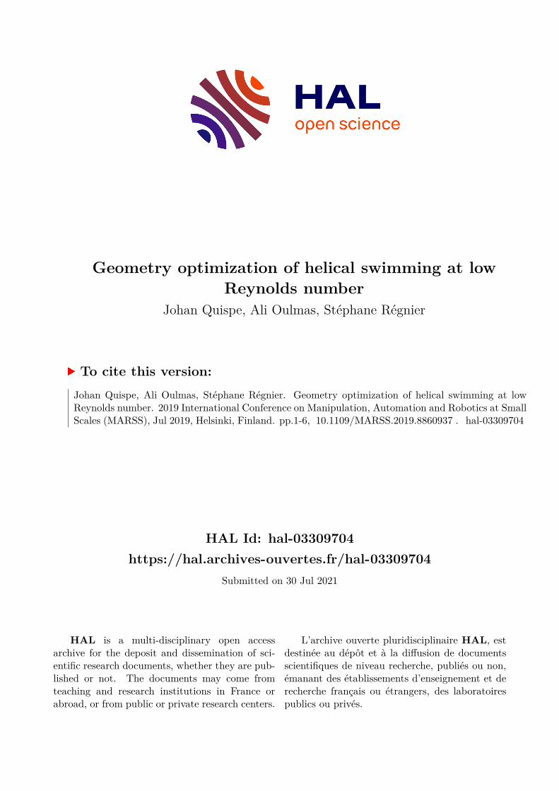
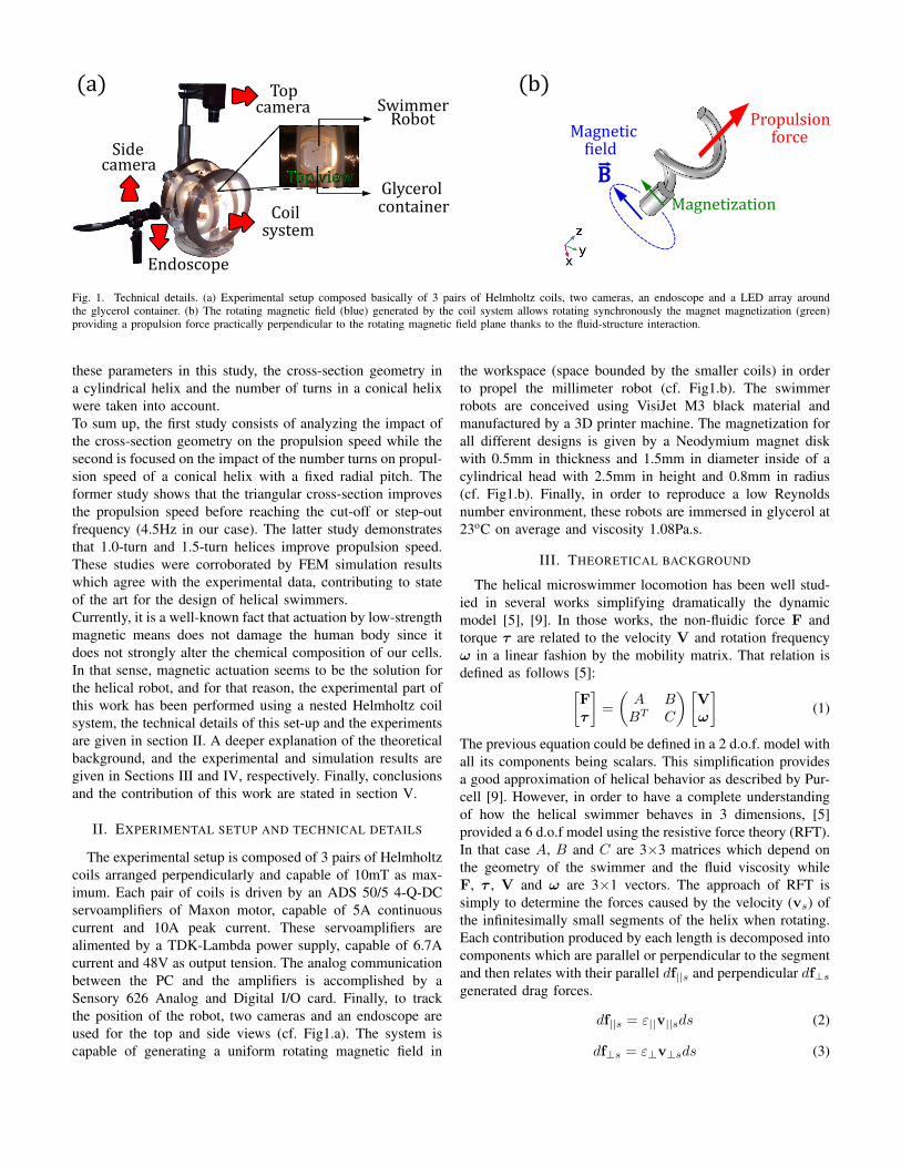
Fig. 1. Technical details. (a) Experimental setup composed basically of 3 pairs of Helmholtz coils, two cameras, an endoscope and a LED array aroundthe glycerol container. (b) The rotating magnetic field (blue) generated by the coil system allows rotating synchronously the magnet magnetization (green)providing a propulsion force practically perpendicular to the rotating magnetic field plane thanks to the fluid-structure interaction.
these parameters in this study, the cross-section geometry ina cylindrical helix and the number of turns in a conical helixwere taken into account.To sum up, the first study consists of analyzing the impact ofthe cross-section geometry on the propulsion speed while thesecond is focused on the impact of the number turns on propul-sion speed of a conical helix with a fixed radial pitch. Theformer study shows that the triangular cross-section improvesthe propulsion speed before reaching the cut-off or step-outfrequency (4.5Hz in our case). The latter study demonstratesthat 1.0-turn and 1.5-turn helices improve propulsion speed.These studies were corroborated by FEM simulation resultswhich agree with the experimental data, contributing to stateof the art for the design of helical swimmers.Currently, it is a well-known fact that actuation by low-strengthmagnetic means does not damage the human body since itdoes not strongly alter the chemical composition of our cells.In that sense, magnetic actuation seems to be the solution forthe helical robot, and for that reason, the experimental part ofthis work has been performed using a nested Helmholtz coilsystem, the technical details of this set-up and the experimentsare given in section II. A deeper explanation of the theoreticalbackground, and the experimental and simulation results aregiven in Sections III and IV, respectively. Finally, conclusionsand the contribution of this work are stated in section V.
II. EXPERIMENTAL SETUP AND TECHNICAL DETAILS
The experimental setup is composed of 3 pairs of Helmholtzcoils arranged perpendicularly and capable of 10mT as max-imum. Each pair of coils is driven by an ADS 50/5 4-Q-DCservoamplifiers of Maxon motor, capable of 5A continuouscurrent and 10A peak current. These servoamplifiers arealimented by a TDK-Lambda power supply, capable of 6.7Acurrent and 48V as output tension. The analog communicationbetween the PC and the amplifiers is accomplished by aSensory 626 Analog and Digital I/O card. Finally, to trackthe position of the robot, two cameras and an endoscope areused for the top and side views (cf. Fig1.a). The system iscapable of generating a uniform rotating magnetic field in
the workspace (space bounded by the smaller coils) in orderto propel the millimeter robot (cf. Fig1.b). The swimmerrobots are conceived using VisiJet M3 black material andmanufactured by a 3D printer machine. The magnetization forall different designs is given by a Neodymium magnet diskwith 0.5mm in thickness and 1.5mm in diameter inside of acylindrical head with 2.5mm in height and 0.8mm in radius(cf. Fig1.b). Finally, in order to reproduce a low Reynoldsnumber environment, these robots are immersed in glycerol at23oC on average and viscosity 1.08Pa.s.
III. THEORETICAL BACKGROUND
The helical microswimmer locomotion has been well stud-ied in several works simplifying dramatically the dynamicmodel [5], [9]. In those works, the non-fluidic force F andtorque τ are related to the velocity V and rotation frequencyω in a linear fashion by the mobility matrix. That relation isdefined as follows [5]:[
Fτ
]=
(A BBT C
)[Vω
](1)
The previous equation could be defined in a 2 d.o.f. model withall its components being scalars. This simplification providesa good approximation of helical behavior as described by Pur-cell [9]. However, in order to have a complete understandingof how the helical swimmer behaves in 3 dimensions, [5]provided a 6 d.o.f model using the resistive force theory (RFT).In that case A, B and C are 3×3 matrices which depend onthe geometry of the swimmer and the fluid viscosity whileF, τ , V and ω are 3×1 vectors. The approach of RFT issimply to determine the forces caused by the velocity (vs) ofthe infinitesimally small segments of the helix when rotating.Each contribution produced by each length is decomposed intocomponents which are parallel or perpendicular to the segmentand then relates with their parallel df||s and perpendicular df⊥sgenerated drag forces.
df||s = ε||v||sds (2)
df⊥s = ε⊥v⊥sds (3)
Being ε|| and ε⊥ the parallel and perpendicular drag coeffi-cients. Finally, when having the force expressions integratethem over the whole swimmer length thus obtaining thetotal force. Though the approximation is feasible for longmicrometer helices, they just have considered the helix cross-section as circular since they use the rod drag coefficients.These approximations do not take into account the effect onthe swimming performances of different cross-section geome-tries with the same area. So, this work proposes a completeformulation of the problem in order to consider the cross-section effect on swimmer performances.The real problem is based on the interaction of the helixstructure with the fluid, fluid-structure interaction (FSI) prob-lem. That implies Navier-Stokes (N-S) equations (Ωf fluiddomain), the rotating structure dynamic (Ωs structure domain)and a boundary condition (∂Ωfs fluid-structure boundary)that relates both equations through all time evolution (τtime interval). N-S equations describe fluid dynamics andare composed of the momentum conservation and the massconservation equation. They are expressed as follows:
∂u
∂t+ ρ(u.∇)u = ∇.Γ + F in Ωf × τ (4)
∂ρ
∂t+∇(ρ.u) = 0 in Ωf × τ (5)
Γ = −pI + µ(∇u + (∇u)T )− 2
3µ(∇.u) (6)
Where u is the fluid velocity, p the pressure, ρ the den-sity, µ the dynamic viscosity, Γ depicting the stress on aninfinitesimal fluid volume (∇.Γ surface forces) and F thevolume forces. However, when studying these equations in adimensionless fashion, a dimensionless quantity appears calledReynolds number. This quantity gives an idea of the viscosityfvis and inertial fin forces. Its definition is given by:
Re =finfvis
=ρV L
µ(7)
Where V is the swimmer robot velocity and L its characteris-tic length. Considering the volume force effects are negligiblesuch it used to happen at the microscale, the momentumequation can be reduced to:
Re(∂u∗
∂t+ ρ(u∗.∇)u∗) = −∇p∗ +∇2u∗ in Ωf × τ (8)
If Re 1, viscous effects dominate over inertial ones, thefinal expression can be rewritten as:
∇p∗ = ∇2u∗ in Ωf × τ (9)
The notation * is for the dimensionless quantities.Concerning the rigid robot structure, a rotation movementis along the robot helix axis. That can be translated in aprescribed mesh motion (dX) since there is no structuredeformation.
dX = dX(rbp, ω, t) in Ωm × τ (10)
Where rbp is the helix axis, ω is the angular frequency andt is time and Ωm ⊂ Ωs. The boundary condition in ∂Ωfs
that stands for the coupling between N-S equations and thestructure movement is given by:
u = us in ∂Ωfs × τ (11)
us =∂X
∂tin ∂Ωfs × τ (12)
Where us is the solid structure velocity in one point situatedon its surface. Another boundary condition in the limits of thecontainer (∂Ωf ) is:
u = 0 in ∂Ωf × τ (13)
Null fluid speed in the fluid-container boundary. Finally, forcecomponents are computed by integrating the total stress (Γ)over all the robot’s surface.
Fi =
∫∂Ωs
Γnf .eids in ∂Ωfs × τ (14)
Being i = x, y, and z for all different components, nf thenormal vector to the surface of each finite element on the robotsurface, ds the surface element, and finally, ei representing theunit vectors for x, y, and z of the global frame.
IV. EXPERIMENTAL AND SIMULATION RESULTS
This current study deals with helical swimmers with differ-ent cross-sections in order to see their influence on the propul-sion speed (via experiments) and the computed propulsionforce (via FEM simulations in COMSOL). The simulationshave considered a fixed helical structure rotating about the he-lix principal axis, then the stress generated along all its surfaceis computed in the stationary regime and integrate it to havethe total force in all directions. Because the simulations onlyconsider the rotational motion that is imposed on the robot,there is not exists cut-off frequency. So, cut-off frequenciesare imposed based on the experimental results.
A. Different cross-section geometries study
The first experiment considers three helical swimmers withpractically the same weight but different cross-section geome-tries, namely an equilateral triangle, a square, and a circle.In order to achieve the same weight for all robots, we haveconsidered the same value of cross-section area before theirsweeping over the helix spine. It means if we consider acircle with radius r, then a square with side l = 1.77rand an equilateral triangle with side L = 2.69r will havethe same area. Moreover, the surface area that interacts withthe surrounding fluid for each robot after sweeping will beproportional to their perimeter (table I). In our case thecircular cross-section radius is 0.4mm while the consideredhelix parameterization in its general form is:
x = acos(t) (15)
y = asin(t) (16)
z = ct (17)
Where a, c and t ε IR. In the conceived helices, these valuesare a = 0.6mm, c = 4mm and t ε [0, 2πn] with n = 2-turns.
0 1 2 3 4 50
0.2
0.4
0.6
0.8
1
1.2
1.4
frequence [Hz]
Vite
sse
to
tal [m
m/s
]
Triangule
Carré
Circle
To
tal
spe
ed
(m
m/
s)
Rotational frequency (Hz)
Triangular
CircularQuadrangular
Experimental data
Simulation data
Fo
rce
/ W
eig
ht
Rotational frequency (Hz)
(c)
Sec. Triangulaire Sec. Carre Sec. Circulaire0
2
4
6
8
10
12
14
Poids (mg)
Volume(mm3)
Weight (mg)
Volume (mm3)
CircularQuadrangularTriangular
(a)
(b)Simulation data
cut-off
frequency
Rotational frequency (Hz)
Fo
rce
/ W
eig
ht
cut-off
frequency
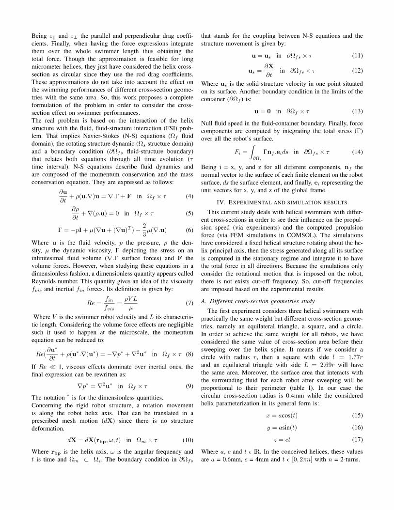
Fig. 2. First experiment considering 3 helical swimmers with practically the same weight and different cross-section geometries. (a) Conceived robots andtheir respective CAD designs for different cross-sections, there exists some differences because of the 3D impression resolution. (b) A bar graph representingthe weight and volume of each robot. (c) Experimental data and simulation results, the former depicts the total speed vs. rotation frequency while the lattershows Force/Weight vs. the rotation frequency. For each helical robot, the experiments were performed three times for each frequency, and the error bar isthe standard deviation of those trials. Besides, the force was computed by integration of the stress generated on the robot surface by its rotation within theviscous medium and then divided by the robot’s weights.
TABLE IDIFFERENT CROSS-SECTION PERIMETERS
PerimeterCircle Triangle Square6.28r 8.08r 7.08r
Fig. 2.a depicts the three printed swimmer and their re-spective CAD representations. The weight and its volumewere measured using a precision balance and the CAD,respectively. These results are depicted in Fig. 2.b. There isa slight difference of 1mg because of different factors suchas the voxel precision of the printing machine and somesmall modifications in the CAD because of wrong boundaryerrors when printing due to the printer software. However,despite these small differences, experimental and simulationresults have shown better performances in terms of speedand ratio Force/Weight for the helical robot with a triangularcross-section (cf. Fig.2.c). Knowing that forces on the robotsdepend upon the interaction of the fluid with their surfaces.There exists a correlation between the surface area of thehelical structures and the forces acting on them. Having agreater helical-shaped surface, the forces on the surface will
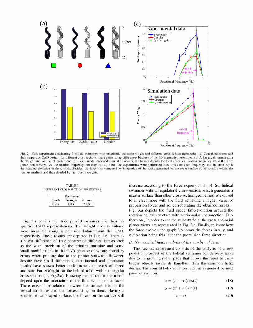
increase according to the force expression in 14. So, helicalswimmer with an equilateral cross-section, which generates agreater surface than other cross-section geometries, is exposedto interact more with the fluid achieving a higher value ofpropulsion force, and so, corroborating the obtained results.Fig. 3.a depicts the fluid speed time-evolution around therotating helical structure with a triangular cross-section. Fur-thermore, in order to see the velocity field, the cross and axialplanes views are represented in Fig. 3.c. Finally, to know howthe force evolves, the graph 3.b shows the forces in x, y, andz-direction being this latter the propulsion force direction.
B. New conical helix analysis of the number of turns
This second experiment consists of the analysis of a newpotential prospect of the helical swimmer for delivery tasksdue to its growing radial pitch that allows the robot to carrybigger objects inside its flagellum than the common helixdesign. The conical helix equation is given in general by nextparameterization:
x = (β + αt)cos(t) (18)
y = (β + αt)sin(t) (19)
z = ct (20)
Axial plane view
Velocity ield
Cross plane view
t=0.0 t=1.0 t=2.0
Fz
(a) (c)
(b)
Fo
rce (
N)
*
*
luid speed (mm/s)
Fx
Fy
Time (s)
Fig. 3. Time evolution analysis for a helical structure rotating at 1.5-turns/s. (a) Color representation of the fluid speed around the rotational motion ofthe robot structure with a triangular section for different times. (b) Force evolution through the time for x, y, and z-axis. (c) Velocity field view in twocross-sectional planes (top part) and one axial cut (bottom part).
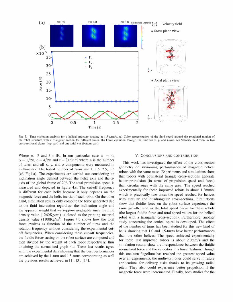
Where α, β and t ε IR. In our particular case β = 0,α = 1/2π, c = 4/2π and t = [0, 2nπ] where n is the numberof turns and all x, y, and z components were measured inmillimeters. The tested number of turns are 1, 1.5, 2.5, 3.5(cf. Fig4.a). The experiments are carried out considering aninclination angle defined between the helix axis and the z-axis of the global frame of 20o. The total propulsion speed ismeasured and depicted in figure 4.c. The cut-off frequencyis different for each helix because it only depends on themagnetic force and the helix inertia of each robot. On the otherhand, simulation results only compute the force generated dueto the fluid interaction regardless the inclination angle andthe apparent weight that we suppose negligible since the fluiddensity value (1260Kg/m3) is closed to the printing materialdensity value (1100Kg/m3). Figure 4.b shows how the totalforce evolves as function of the number of turns and therotation frequency without considering the experimental cut-off frequencies. When considering these cut-off frequencies,the fluidic forces acting on the robot surface are computed andthen divided by the weight of each robot respectively, thusobtaining the normalized graph 4.d. These last results agreewith the experimental data showing that the best performancesare achieved by the 1-turn and 1.5-turns corroborating as wellthe previous results achieved in [1], [3], [14].
V. CONCLUSIONS AND CONTRIBUTION
This work has investigated the effect of the cross-sectiongeometry on swimming performances of magnetic helicalrobots with the same mass. Experiments and simulations showthat robots with equilateral triangle cross-sections generatebetter propulsion (in terms of propulsion speed and force)than circular ones with the same area. The speed reachedexperimentally for these improved robots is about 1.2mm/s,which is practically two times the speed reached for heliceswith circular and quadrangular cross-sections. Simulationsshow that fluidic force on the robot surface experience thesame growth trend as the total speed curve for these robots(the largest fluidic force and total speed values for the helicalrobot with a triangular cross-section). Furthermore, anotherstudy concerning the conical spiral is developed. The effectof the number of turns has been studied for this new kind ofhelix showing that 1.0 and 1.5-turns have better performancesthan the other helices. The speed achieved experimentallyfor these last improved robots is about 2.0mm/s and thesimulation results show a correspondence between the fluidicnormalized force and the velocities in a linear fashion. Thoughthis one-turn flagellum has reached the greatest speed valueover all experiments, the multi-turn ones could serve in futureapplications for delivery tasks thanks to its growing radialpitch. They also could experience better propulsion if themagnetic force were incremented. Finally, both studies for the
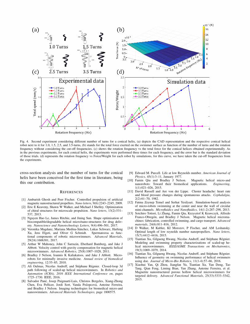
Fig. 4. Second experiment considering different number of turns for a conical helix, (a) depicts the CAD representation and the respective conical helicalrobot next to it for 1.0, 1.5, 2.5, and 3.5-turns, (b) stands for the total force exerted on the swimmer surface as function of the number of turns and the rotationfrequency without considering the cut-off frequencies. (c) shows the rotation frequency vs the total force for the conical helices obtained experimentally. Asin the previous experiments, for each conical helix, the experiments were performed three times for each frequency, and the error bar is the standard deviationof those trials. (d) represents the rotation frequency vs Force/Weight for each robot by simulations, for this curve, we have taken the cut-off frequencies fromthe experiments.
cross-section analysis and the number of turns for the conicalhelix have been conceived for the first time in literature, beingthis our contribution.
REFERENCES
[1] Ambarish Ghosh and Peer Fischer. Controlled propulsion of artificialmagnetic nanostructured propellers. Nano letters, 9(6):2243–2245, 2009.
[2] Eric E Keaveny, Shawn W Walker, and Michael J Shelley. Optimizationof chiral structures for microscale propulsion. Nano letters, 13(2):531–537, 2013.
[3] Nguyen Hao Le, James Ritchie, and Jining Sun. Shape optimisation ofbiocompatible/degradable helical micro/nano-structures for drug deliv-ery. Nanoscience and Nanotechnology Letters, 9(4):496–501, 2017.
[4] Veronika Magdanz, Mariana Medina-Sanchez, Lukas Schwarz, HaifengXu, Jens Elgeti, and Oliver G Schmidt. Spermatozoa as func-tional components of robotic microswimmers. Advanced Materials,29(24):1606301, 2017.
[5] Arthur W Mahoney, John C Sarrazin, Eberhard Bamberg, and Jake JAbbott. Velocity control with gravity compensation for magnetic helicalmicroswimmers. Advanced Robotics, 25(8):1007–1028, 2011.
[6] Bradley J Nelson, Ioannis K Kaliakatsos, and Jake J Abbott. Micro-robots for minimally invasive medicine. Annual review of biomedicalengineering, 12:55–85, 2010.
[7] Ali Oulmas, Nicolas Andreff, and Stephane Regnier. Closed-loop 3dpath following of scaled-up helical microswimmers. In Robotics andAutomation (ICRA), 2016 IEEE International Conference on, pages1725–1730. IEEE, 2016.
[8] Salvador Pane, Josep Puigmartı-Luis, Christos Bergeles, Xiang-ZhongChen, Eva Pellicer, Jordi Sort, Vanda Pocepcova, Antoine Ferreira,and Bradley J Nelson. Imaging technologies for biomedical micro-andnanoswimmers. Advanced Materials Technologies, page 1800575.
[9] Edward M. Purcell. Life at low Reynolds number. American Journal ofPhysics, 45(1):3–11, January 1977.
[10] Famin Qiu and Bradley J Nelson. Magnetic helical micro-andnanorobots: Toward their biomedical applications. Engineering,1(1):021–026, 2015.
[11] David Russell and Are von der Lippe. Cluster headache: heart rateand blood pressure changes during spontaneous attacks. Cephalalgia,2(2):61–70, 1982.
[12] Fatma Zeynep Temel and Serhat Yesilyurt. Simulation-based analysisof micro-robots swimming at the center and near the wall of circularmini-channels. Microfluidics and Nanofluidics, 14(1-2):287–298, 2013.
[13] Soichiro Tottori, Li Zhang, Famin Qiu, Krzysztof K Krawczyk, AlfredoFranco-Obregon, and Bradley J Nelson. Magnetic helical microma-chines: fabrication, controlled swimming, and cargo transport. Advancedmaterials, 24(6):811–816, 2012.
[14] D Walker, M Kubler, KI Morozov, P Fischer, and AM Leshansky.Optimal length of low reynolds number nanopropellers. Nano letters,15(7):4412–4416, 2015.
[15] Tiantian Xu, Gilgueng Hwang, Nicolas Andreff, and Stephane Regnier.Modeling and swimming property characterizations of scaled-up he-lical microswimmers. IEEE/ASME Transactions on Mechatronics,19(3):1069–1079, 2014.
[16] Tiantian Xu, Gilgueng Hwang, Nicolas Andreff, and Stephane Regnier.Influence of geometry on swimming performance of helical swimmersusing doe. Journal of Micro-Bio Robotics, 11(1-4):57–66, 2016.
[17] Xiaohui Yan, Qi Zhou, Jiangfan Yu, Tiantian Xu, Yan Deng, TaoTang, Qian Feng, Liming Bian, Yan Zhang, Antoine Ferreira, et al.Magnetite nanostructured porous hollow helical microswimmers fortargeted delivery. Advanced Functional Materials, 25(33):5333–5342,2015.


![Lecture 12. Life in the low Reynolds-number worldphysics.bnu.edu.cn/application/faculty/tuzhanchun/...swimming in the low-Reynolds world [Purcell (1977) Am. J. Phys.] The required](https://img.pdfslide.us/doc/110x75/5e6fbc411acdc7592456237a/lecture-12-life-in-the-low-reynolds-number-swimming-in-the-low-reynolds-world.jpg)