Embed Size (px)
DESCRIPTION
Geometric Correction. It is vital for many applications using remotely sensed images to know the ground locations for points in the image. There are two similar processes that can help build the link between images and real world locations: image-to-map rectification - PowerPoint PPT Presentation
Citation preview
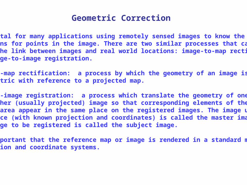
Geometric Correction
It is vital for many applications using remotely sensed images to know the ground locations for points in the image. There are two similar processes that can help build the link between images and real world locations: image-to-map rectification and image-to-image registration.
Image-to-map rectification: a process by which the geometry of an image is made planimetric with reference to a projected map.
Image-to-image registration: a process which translate the geometry of one image to another (usually projected) image so that corresponding elements of the same ground area appear in the same place on the registered images. The image used as reference (with known projection and coordinates) is called the master image, and the image to be registered is called the subject image.
It is important that the reference map or image is rendered in a standard map projection and coordinate systems.
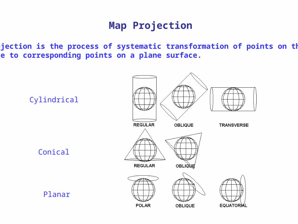
Map Projection
Map projection is the process of systematic transformation of points on the Earth’s surface to corresponding points on a plane surface.
Cylindrical
Conical
Planar
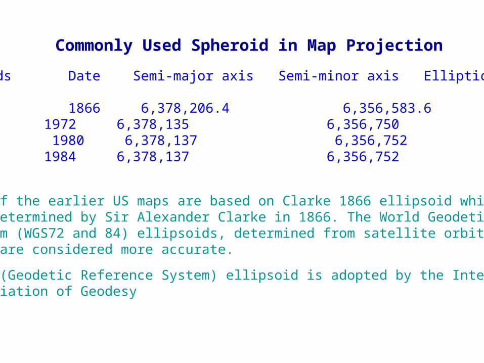
Commonly Used Spheroid in Map Projection
Ellipsoids Date Semi-major axis Semi-minor axis Ellipticity
Clarke 1866 6,378,206.4 6,356,583.6 1/294.98WGS72 1972 6,378,135 6,356,750 1/298.26GRS80 1980 6,378,137 6,356,752 1/298.257WGS84 1984 6,378,137 6,356,752 1/298.257…
Many of the earlier US maps are based on Clarke 1866 ellipsoid which was determined by Sir Alexander Clarke in 1866. The World Geodetic System (WGS72 and 84) ellipsoids, determined from satellite orbital data are considered more accurate.
GRS80 (Geodetic Reference System) ellipsoid is adopted by the International Association of Geodesy
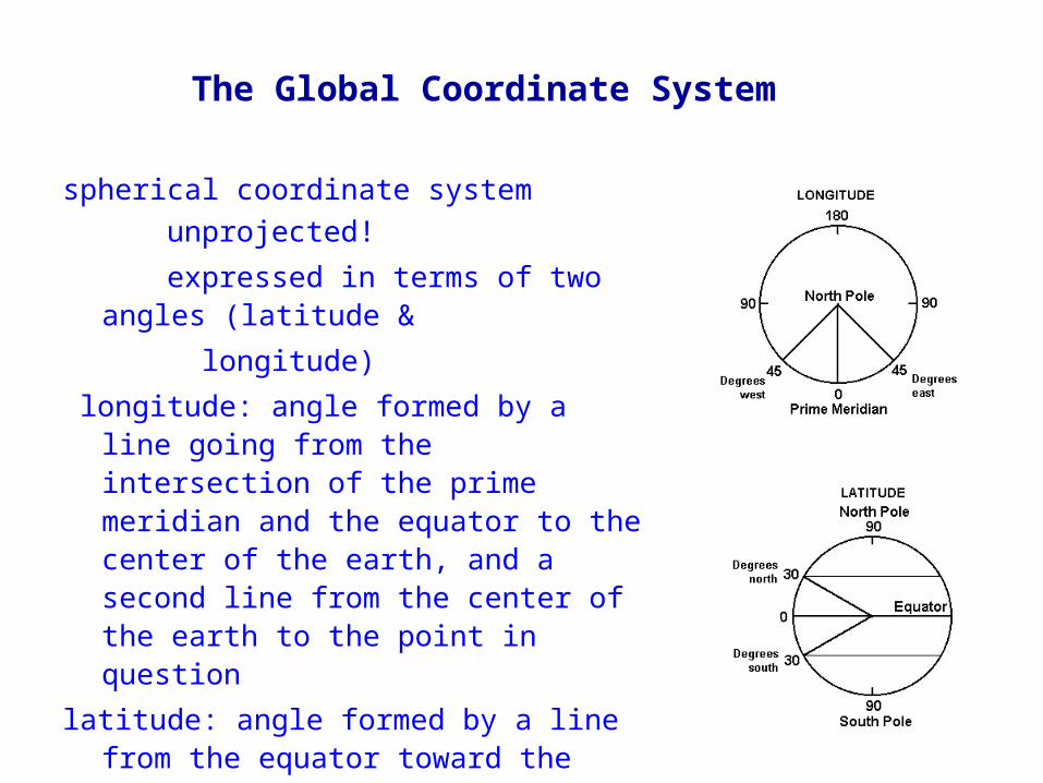
The Global Coordinate System
spherical coordinate system unprojected! expressed in terms of two angles (latitude & longitude) longitude: angle formed by a line going from the
intersection of the prime meridian and the equator to the center of the earth, and a second line from the center of the earth to the point in question
latitude: angle formed by a line from the equator toward the center of the earth, and a second line perpendicular to the reference ellipsoid at the point in question
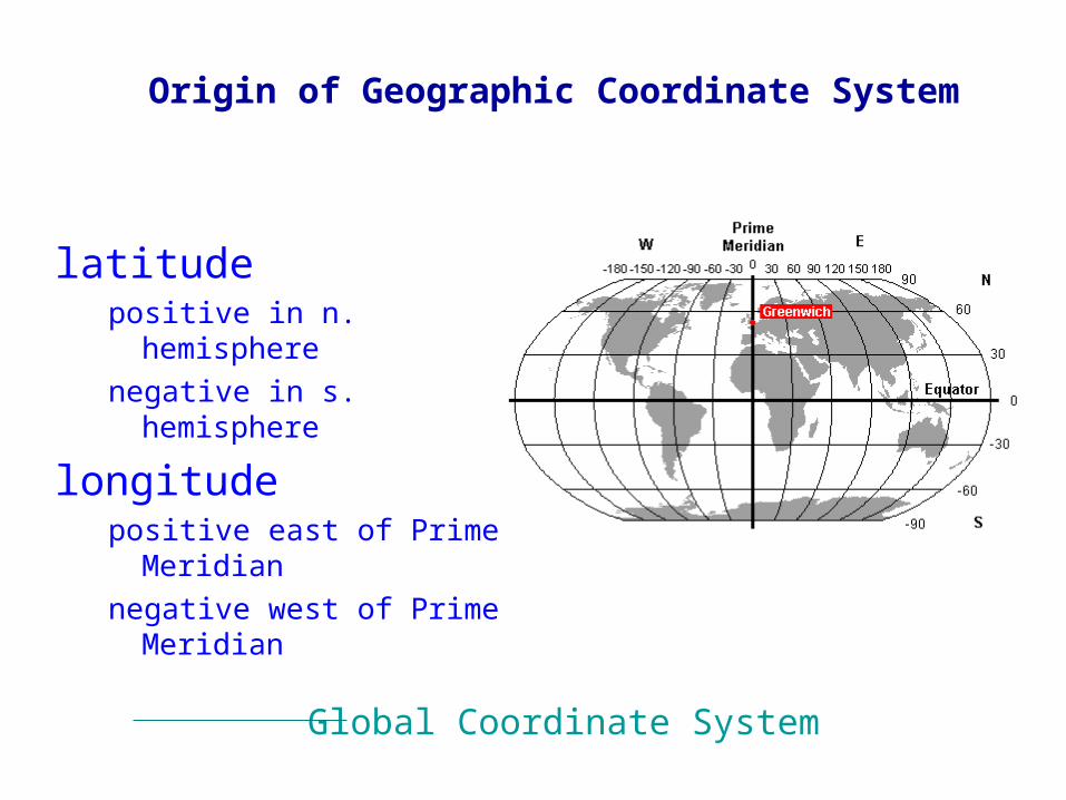
latitudepositive in n. hemispherenegative in s. hemisphere
longitudepositive east of Prime Meridiannegative west of Prime Meridian
Origin of Geographic Coordinate System
Global Coordinate System
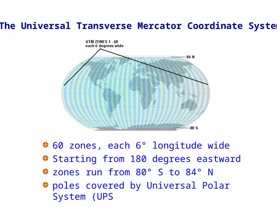
The Universal Transverse Mercator Coordinate System
60 zones, each 6° longitude wideStarting from 180 degrees eastwardzones run from 80° S to 84° Npoles covered by Universal Polar System (UPS
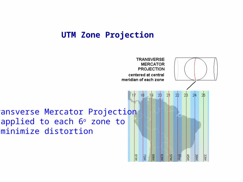
Transverse Mercator Projection applied to each 6o zone to minimize distortion
UTM Zone Projection
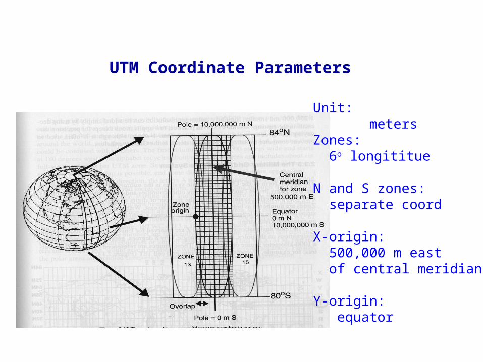
UTM Coordinate Parameters
Unit: metersZones: 6o longititue
N and S zones: separate coord
X-origin: 500,000 m east of central meridian
Y-origin: equator
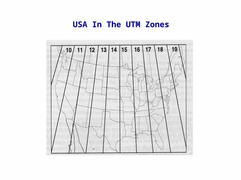
USA In The UTM Zones
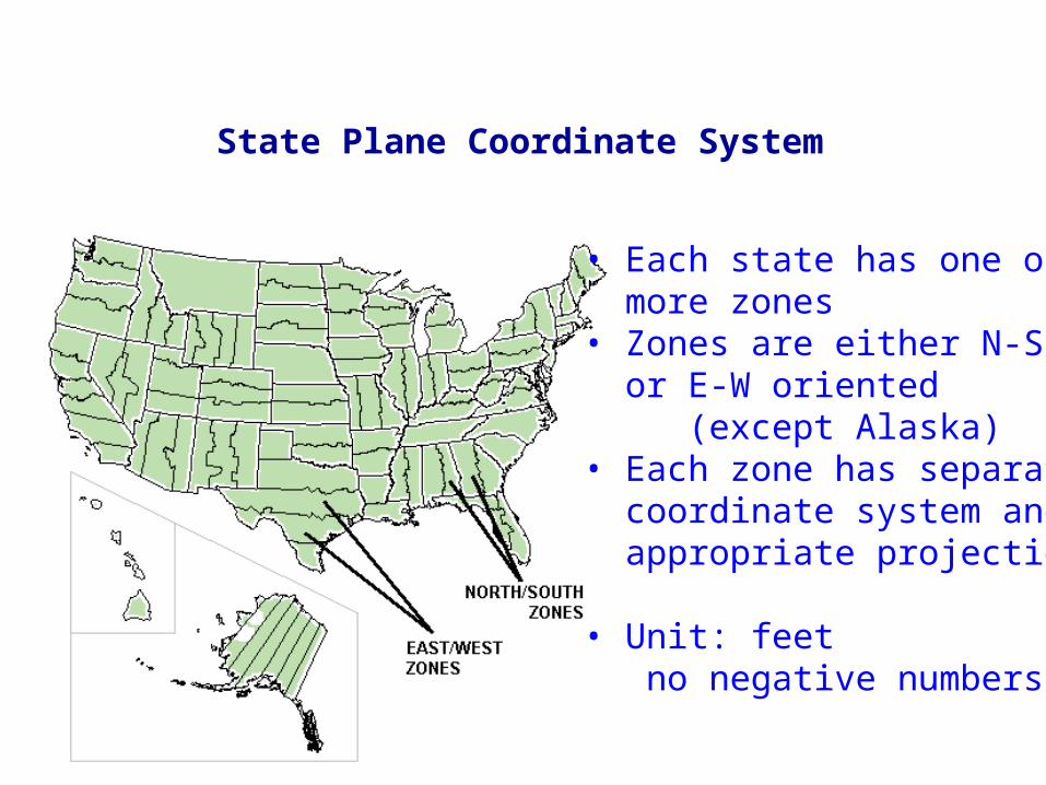
State Plane Coordinate System
• Each state has one or more zones• Zones are either N-S or E-W oriented (except Alaska)• Each zone has separate coordinate system and appropriate projection
• Unit: feet no negative numbers
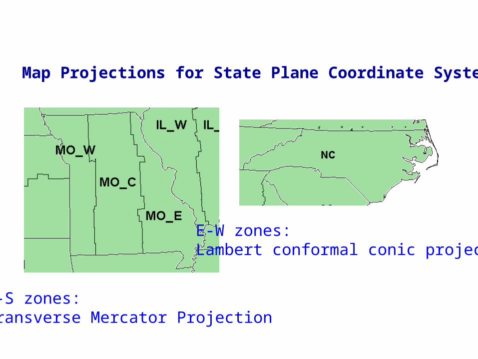
Map Projections for State Plane Coordinate System
N-S zones: Transverse Mercator Projection
E-W zones: Lambert conformal conic projection
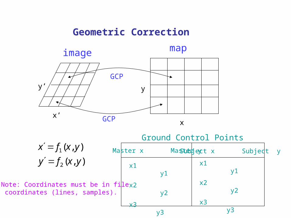
Geometric Correction
x’
y’
x
y
image map
GCP
GCP
),(),(
2
1
yxfyyxfx
Ground Control PointsMaster x Master y Subject x Subject y
x1 y1
x2 y2
x3 y3
… …
x1 y1
x2 y2
x3 y3
… …
Note: Coordinates must be in file coordinates (lines, samples).
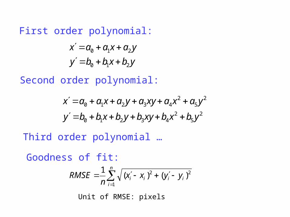
First order polynomial:
ybxbbyyaxaax
210
210
Second order polynomial:
25
243210
25
243210
ybxbxybybxbby
yaxaxyayaxaax
Third order polynomial …
Goodness of fit:
n
iiiii yyxx
nRMSE
1
22 )()(1
Unit of RMSE: pixels
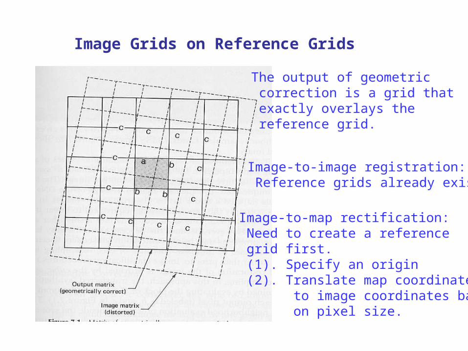
Image Grids on Reference Grids
The output of geometric correction is a grid that exactly overlays the reference grid.
Image-to-image registration: Reference grids already exist.
Image-to-map rectification: Need to create a reference grid first. (1). Specify an origin (2). Translate map coordinates to image coordinates based on pixel size.
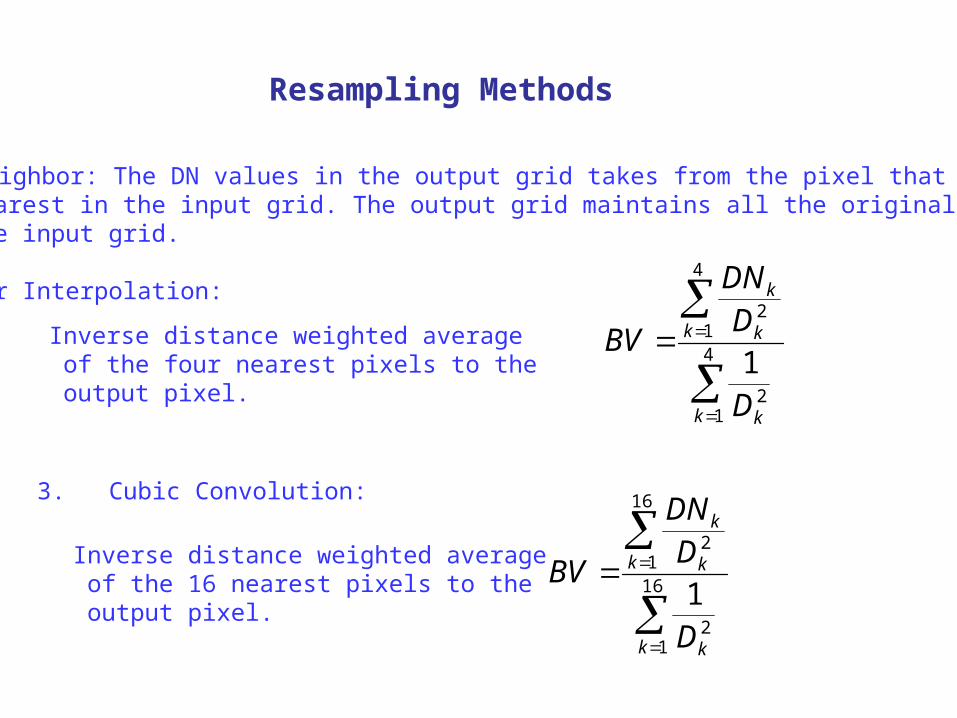
Resampling Methods
1. Nearest Neighbor: The DN values in the output grid takes from the pixel that is nearest in the input grid. The output grid maintains all the original DN values in the input grid. 2. Bilinear Interpolation:
4
12
4
12
1k k
k k
k
D
DDN
BVInverse distance weighted average of the four nearest pixels to the output pixel.
3. Cubic Convolution:
16
12
16
12
1k k
k k
k
D
DDN
BVInverse distance weighted average of the 16 nearest pixels to the output pixel.


![Correction: Statistical Computations on Grassmann and Stiefel …pturaga/papers/GrassmannCorrected.pdf · 2012. 8. 2. · 4 provided in [22]. Algorithmic computations of the geometric](https://img.pdfslide.us/doc/110x75/60ffdd78a4b3b812f1733979/correction-statistical-computations-on-grassmann-and-stiefel-pturagapapersgrassmanncorrectedpdf.jpg)