Embed Size (px)
DESCRIPTION
This portfolio includes my most recent studio projects, as well as hand rendering and professional work.
Citation preview
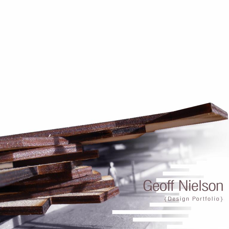
Geoff Nielson{Design Por t fo l io}
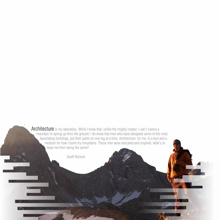
Architecture is my laboratory. While I know that, unlike the mighty creator, I can’t coerce a mountain to spring up from the ground, I do know that men who have designed some of the most
fascinating buildings, put their pants on one leg at a time. Architecture, for me, is a tool and a medium for how I build my mountains. These men were educated and inspired, what’s to
keep me from being the same?
Geoff Nielson
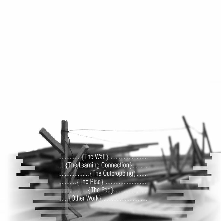
..............{The Wall}........................
....{The Learning Connection}..........
...................{The Outcropping}.......
...........{The Rise}...........................
..................{The Pod}.....................
......{Other Work}.............................
2 3
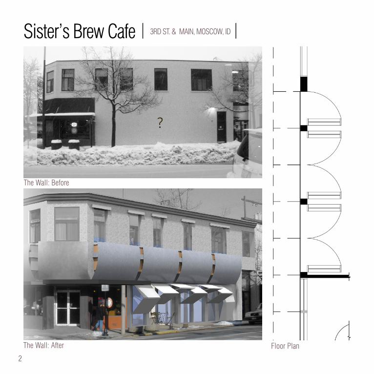
Sister’s Brew Cafe | 3RD ST. & MAIN, MOSCOW, ID |
The Wall: Before
The Wall: After Floor Plan
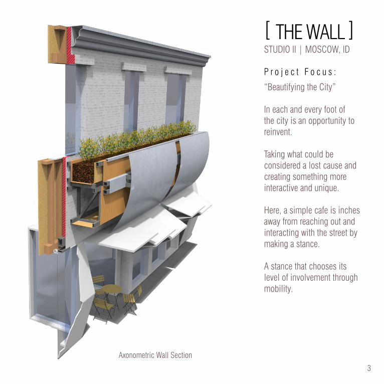
[ THE WALL ]STUDIO II | MOSCOW, ID
P r o j e c t F o c u s :
“Beautifying the City”
In each and every foot of the city is an opportunity to reinvent.
Taking what could be considered a lost cause and creating something more interactive and unique.
Here, a simple cafe is inches away from reaching out and interacting with the street by making a stance.
A stance that chooses its level of involvement through mobility.
2 3
Axonometric Wall Section
4 5
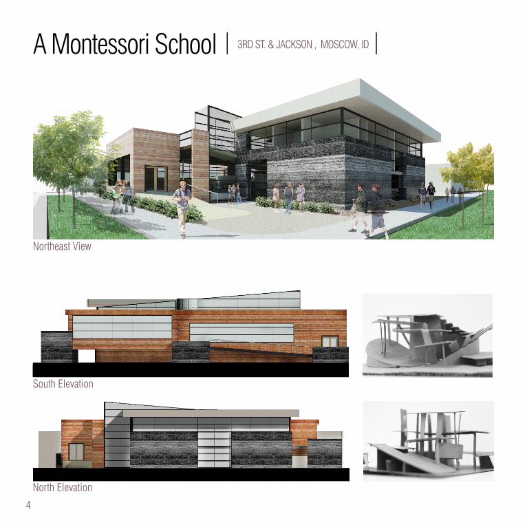
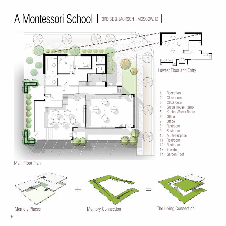
A Montessori School | 3RD ST. & JACKSON , MOSCOW, ID |
South Elevation
North Elevation
Northeast View
4 5
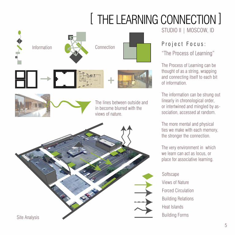
STUDIO II | MOSCOW, ID
P r o j e c t F o c u s :
“The Process of Learning”
The Process of Learning can be thought of as a string, wrapping and connecting itself to each bit of information.
The information can be strung out linearly in chronological order, or intertwined and mingled by as-sociation, accessed at random.
The more mental and physical ties we make with each memory, the stronger the connection.
The very environment in which we learn can act as locus, or place for associative learning.
[ THE LEARNING CONNECTION ]
Softscape
Views of Nature
Forced Circulation
Building Relations
Heat Islands
Building FormsSite Analysis
Information Connection
The lines between outside and in become blurred with the views of nature.
6 7
Memory Places Memory Connection The Living Connection
+ =
1. Reception2. Classroom3. Classroom4. Green House Ramp5. Kitchen/Break Room6. Office 7. Office8. Restroom9. Restroom10. Multi-Purpose11. Restroom12. Restroom13. Elevator14. Garden Roof
1
1
23
11 12
13
10
4
5
6 78
9
1
1
23
11 12
13
10
4
5
6 78
9
Lowest Floor and Entry
Main Floor Plan
A Montessori School | 3RD ST. & JACKSON , MOSCOW, ID |
6 7
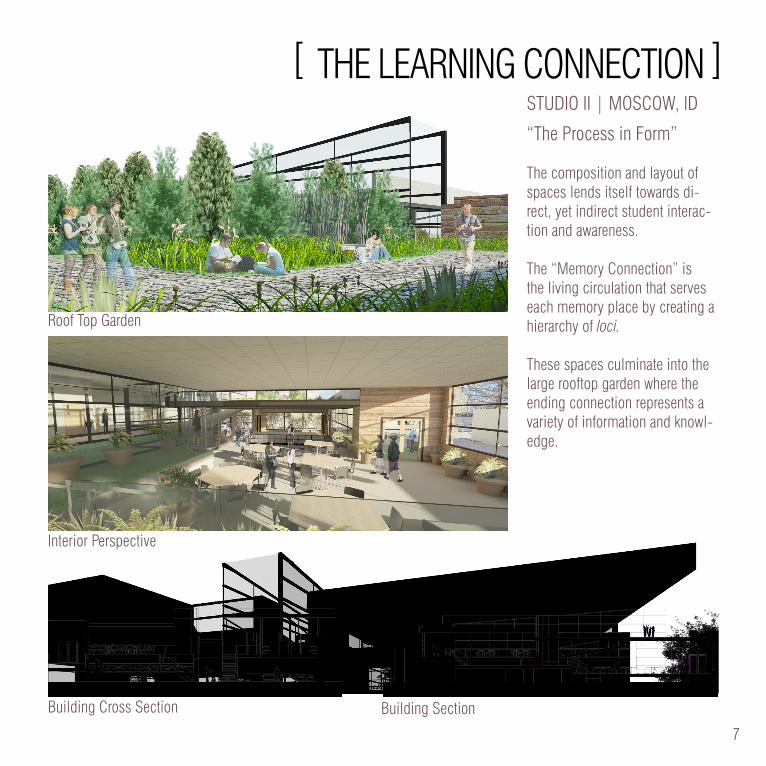
STUDIO II | MOSCOW, ID
“The Process in Form”
The composition and layout of spaces lends itself towards di-rect, yet indirect student interac-tion and awareness.
The “Memory Connection” is the living circulation that serves each memory place by creating a hierarchy of loci.
These spaces culminate into the large rooftop garden where the ending connection represents a variety of information and knowl-edge.
Roof Top Garden
Interior Perspective
Building Cross Section Building Section
[ THE LEARNING CONNECTION ]
8 9
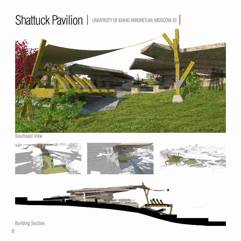
Shattuck Pavilion | UNIVERSITY OF IDAHO ARBORETUM, MOSCOW, ID |
Southeast View
Building Section
8 9
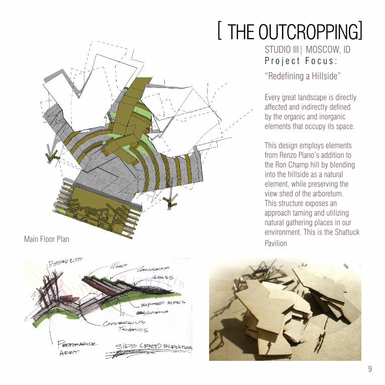
STUDIO III| MOSCOW, IDP r o j e c t F o c u s :
“Redefining a Hillside”
Every great landscape is directly affected and indirectly defined by the organic and inorganic elements that occupy its space.
This design employs elements from Renzo Piano’s addition to the Ron Champ hill by blending into the hillside as a natural element, while preserving the view shed of the arboretum. This structure exposes an approach taming and utilizing natural gathering places in our environment. This is the Shattuck PavilionMain Floor Plan
[ THE OUTCROPPING]
10 11
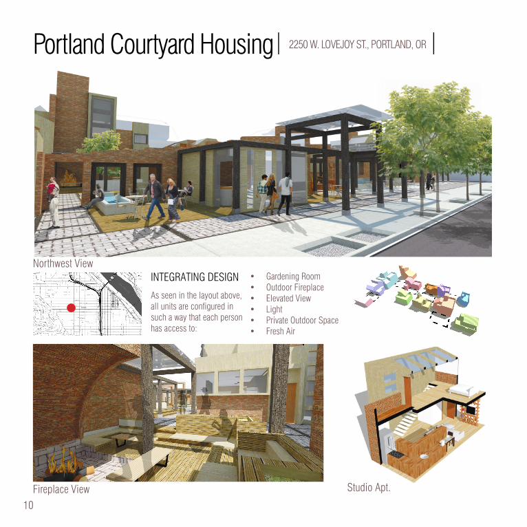
Portland Courtyard Housing| 2250 W. LOVEJOY ST., PORTLAND, OR |
INTEGRATING DESIGN
As seen in the layout above, all units are configured in such a way that each person has access to:
• Gardening Room• Outdoor Fireplace• Elevated View• Light • Private Outdoor Space• Fresh Air
Fireplace View
Northwest View
Studio Apt.
10 11
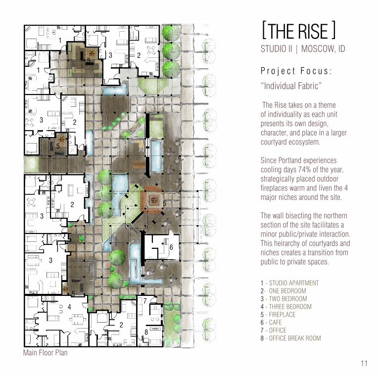
[THE RISE ]STUDIO II | MOSCOW, ID
P r o j e c t F o c u s :
“Individual Fabric”
The Rise takes on a theme of individuality as each unit presents its own design, character, and place in a larger courtyard ecosystem.
Since Portland experiences cooling days 74% of the year, strategically placed outdoor fireplaces warm and liven the 4 major niches around the site.
The wall bisecting the northern section of the site facilitates a minor public/private interaction. This heirarchy of courtyards and niches creates a transition from public to private spaces.
1 - STUDIO APARTMENT2- ONE BEDROOM3 - TWO BEDROOM4 - THREE BEDROOM5 - FIREPLACE 6 - CAFE7 - OFFICE8 - OFFICE BREAK ROOM
23
1
1
3 2
2
3
5
3
4
2
7
8
6
5
5
5
Main Floor Plan
12 13
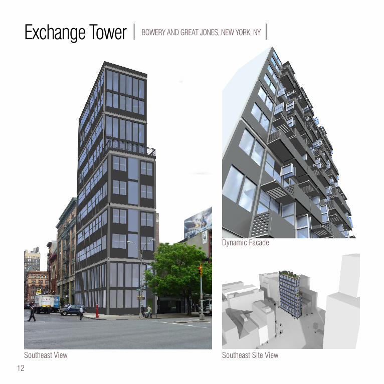
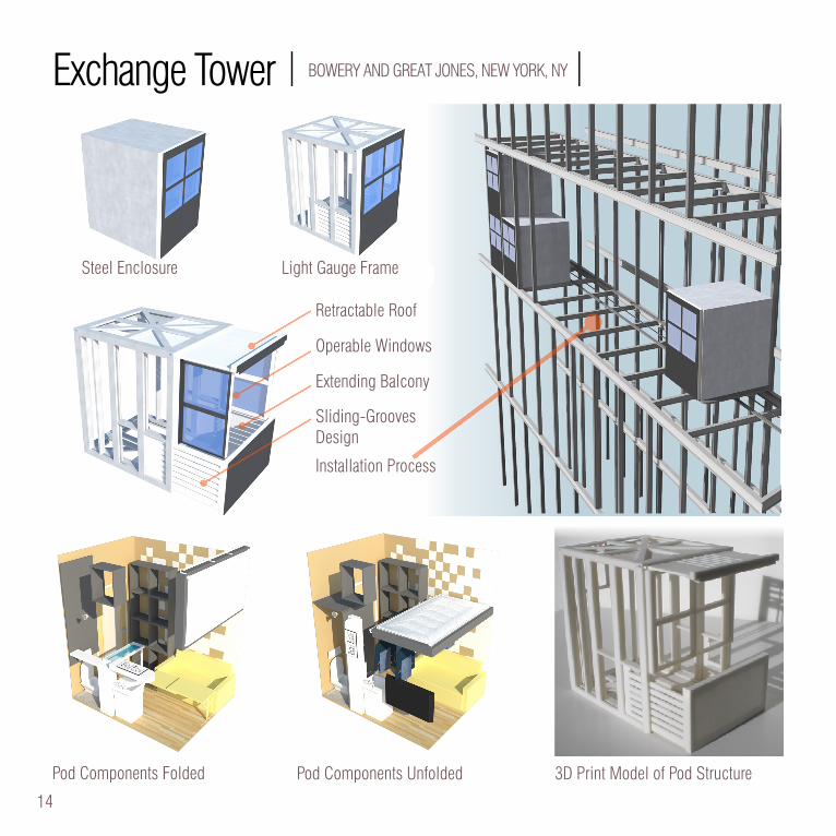
Exchange Tower | BOWERY AND GREAT JONES, NEW YORK, NY |
Southeast View Southeast Site View
Dynamic Facade
12 13
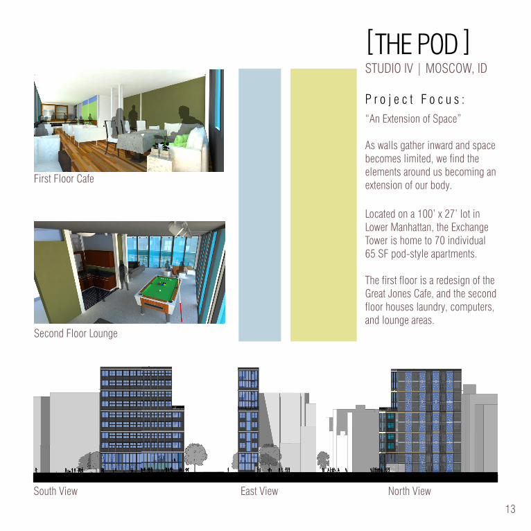
[THE POD ]STUDIO IV | MOSCOW, ID
P r o j e c t F o c u s :“An Extension of Space”
As walls gather inward and space becomes limited, we find the elements around us becoming an extension of our body.
Located on a 100’ x 27’ lot in Lower Manhattan, the Exchange Tower is home to 70 individual 65 SF pod-style apartments.
The first floor is a redesign of the Great Jones Cafe, and the second floor houses laundry, computers, and lounge areas.
PRO
DU
CED
BY
AN
AU
TOD
ESK
ED
UC
ATI
ON
AL
PRO
DU
CT
PRODUCED BY AN AUTODESK EDUCATIONAL PRODUCT
PRO
DU
CED
BY A
N A
UTO
DESK
EDU
CA
TION
AL PR
OD
UC
T
PRODUCED BY AN AUTODESK EDUCATIONAL PRODUCT
PRO
DU
CED
BY A
N A
UTO
DESK
EDU
CA
TION
AL PR
OD
UC
T
PRODUCED BY AN AUTODESK EDUCATIONAL PRODUCT
PRO
DU
CED
BY
AN
AU
TOD
ESK
ED
UC
ATI
ON
AL
PRO
DU
CT
PRODUCED BY AN AUTODESK EDUCATIONAL PRODUCT
Body Space Shape Meeting the goals of this project requires a deeper look at how the body interacts with space and comfortably takes shape in a compact way.
The pod style in this design takes a look at having pre manufactured units, engineered with both exactness and con-sistency. This approach allows for ease in assembly, use, and repair. While designed with precision, the internal and external nature of this building seems quite the opposite
Gaps are an issue in designing in such a compact space. Developers pay for every square foot, and any none- rentable space can be seen as wasteful. How does one de-sign for this? Let’s look at one approach.
XchangeTower.Geoff NielsonFrank JacobusNew York Summer Studio
Perspective Aesthetics, Flow and View
Great Jones Cafe Xchange Tower Lounge
North Elevation 1/8”= 1’-0”East 1/8”= 1’-0”South Elevation 1/8”= 1’-0”
First Floor Cafe
Second Floor Lounge
South View East View North View
14 15
Exterior...
Storage spaces ac-cessible by ladder.
Fold down double size bed
Retractable panels for toilet privacy
Swivel down electric burner and ironing board.
Clothing hangers un-der bed
Collapsible couch ta-ble.
to
...Interior
Pod Components Folded Pod Components Unfolded 3D Print Model of Pod Structure
Exchange Tower | BOWERY AND GREAT JONES, NEW YORK, NY |
Retractable Roof
Operable Windows
Extending Balcony
Sliding-GroovesDesign
Installation Process
Light Gauge FrameSteel Enclosure
14 15
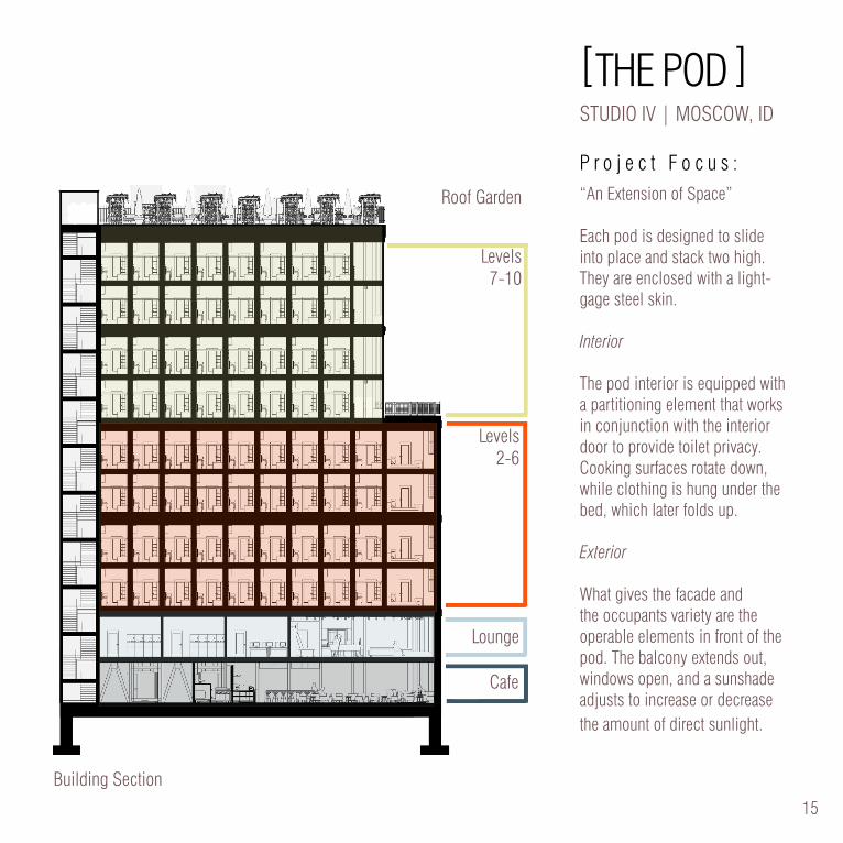
[THE POD ]STUDIO IV | MOSCOW, ID
P r o j e c t F o c u s :“An Extension of Space”
Each pod is designed to slide into place and stack two high. They are enclosed with a light-gage steel skin.
Interior
The pod interior is equipped with a partitioning element that works in conjunction with the interior door to provide toilet privacy. Cooking surfaces rotate down, while clothing is hung under the bed, which later folds up.
Exterior
What gives the facade and the occupants variety are the operable elements in front of the pod. The balcony extends out, windows open, and a sunshade adjusts to increase or decrease the amount of direct sunlight.
Building Section
Cafe
Lounge
Levels 2-6
Levels 7-10
Roof Garden
16 17
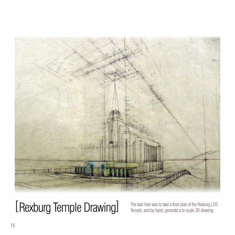
[Rexburg Temple Drawing] The task here was to take a floor plan of the Rexburg LDS Temple, and by hand, generate a to-scale 3D drawing.
16 17
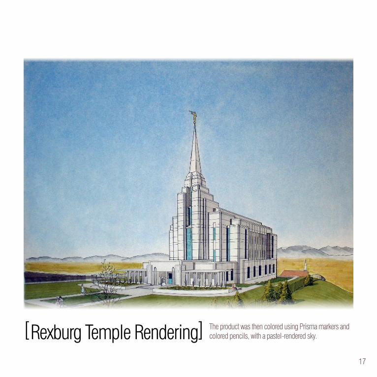
[Rexburg Temple Rendering] The product was then colored using Prisma markers and colored pencils, with a pastel-rendered sky.
18 19
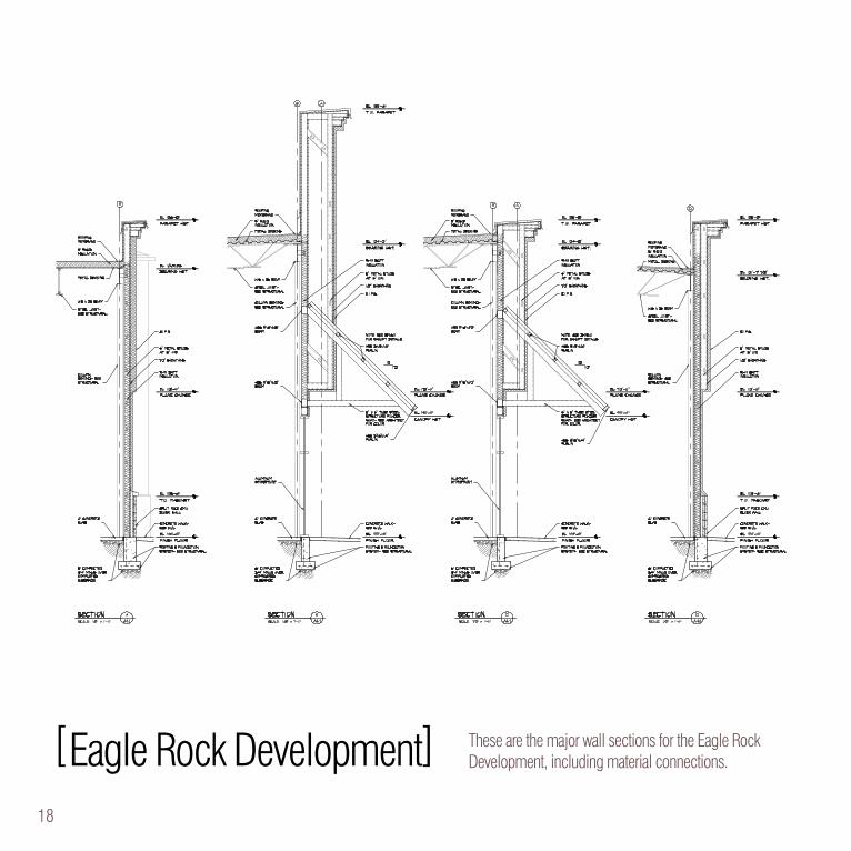
[Eagle Rock Development] These are the major wall sections for the Eagle Rock Development, including material connections.
18 19
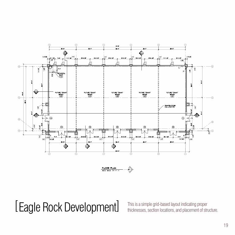
[Eagle Rock Development] This is a simple grid-based layout indicating proper thicknesses, section locations, and placement of structure.
20 21
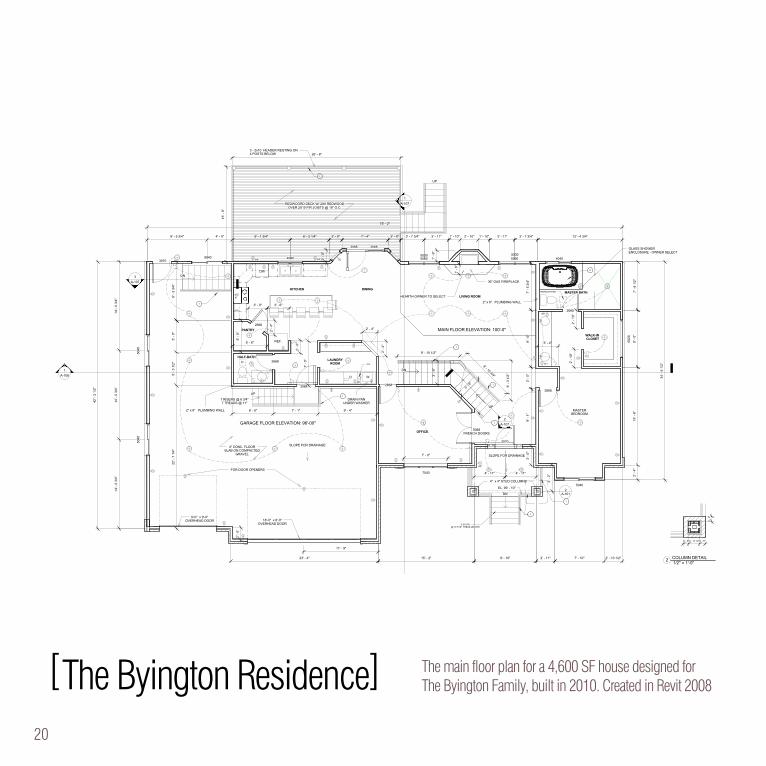
[The Byington Residence] The main floor plan for a 4,600 SF house designed for The Byington Family, built in 2010. Created in Revit 2008
UP
D W
DW
REF.
DN
DN
DN
UP
UP
R
2
2
2
2
D
GFI
GFI
3
GFI
1A-106
1A-107
23' - 4" 15' - 2" 9' - 10" 2' - 11"
7' -
8 1/
2"9'
- 0"
9' -
3 3/
4"
LIVING ROOM
WALK-INCLOSET
MASTERBEDROOM
MASTER BATH.KITCHEN
PANTRY
HALF-BATHLAUNDRY
ROOM
OFFICE
36" GAS FIREPLACE
50505050
42' -
2 1
/2"
4" x 4" STUD COLUMNS
6' - 6" 7' - 1" 9' - 4"
4040
5040
7040 4' - 11" 4' - 11"
11' - 9"
4040
EXHAUST FAN
30683068
5' - 6"
7' -
0"
2868
2668
3070
2868
2" x 6" PLUMBING WALL
5030 5030
22' -
7 1
/4"
5' -
3 1/
2"5'
- 0"
2" x 6" PLUMBING WALL
9'-0" x 9'-0"OVERHEAD DOOR 18'-0" x 8'-0"
OVERHEAD DOOR
4" CONC. FLOORSLAB ON COMPACTED
GRAVEL
SLOPE FOR DRAINAGE
GARAGE FLOOR ELEVATION: 96'-00"
F.D.
2' -
0"
2668
2668
5' -
0"
3' - 0"
2' -
4"
2' -
0"
2' -
0"
3' - 6"
2' -
4"
2' - 4" MAIN FLOOR ELEVATION: 100'-0"
2' - 0" 7' - 4"6' - 2 1/4" 3' - 7 3/4"
9' -
0"3'
- 5"
3' -
0"9'
- 1"
1' -
6"
4' -
2"
9' - 10 1/2"
8' - 10 3/4"
HEARTH OWNER TO SELECT
1
1
5 STEPS@ 10 7/16" TREAD LENGTH
6020
3' - 4"
7' -
5 3/
4"
1
1
1
1' -
9"
26' - 8"
15' -
0"
1
3070
7 RISERS @ 6 3/4"7 TREADS @ 11"
2
A-1012
5040
5040
3'- 9
"
3' -
9"
3A-107
2A-107
6' -
3 1/
2"
5040
SLOPE FOR DRAINAGE
2' -
10"
2' -
10"
14' -
0 3
/4"
14' -
0 3
/4"
14' -
0 3
/4"
3' - 11"1' - 10" 2' - 10" 1' - 10"3' - 11"3' - 7 3/4"
1
FOR DOOR OPENERS
DRAIN PANUNDER WASHER
EF
DINING
2' -
4"15
' - 6
"
34' -
6 1
/2"
7' - 10" 2' - 10 1/2"
3068
GLASS SHOWERENCLOSURE - OWNER SELECT
13' - 4 3/4"
75' - 2"
9' - 5 3/4" 4' - 0" 9' - 1 3/4"
EL. 99' - 10"
WP
WPWP
1
3 - 2x10 HEADER RESTING ON4 POSTS BELOW
REDWOORD DECK W/ 2X6 REDWOODOVER 2X10 FIR JOISTS @ 16" O.C.
5068FRENCH DOORS
2' - 0"
7' - 0"
0' -
5"
0' - 5"0' - 10 1/2"0' - 5"
Scale
Project number
Date
Drawn by
Checked by
As indicated
A-101
MAIN FLOOR PLAN
1
THE BYINGTONFAMILY RESIDENCE
07/27/2009GEOFF NIELSONSCOTT NIELSON
1/4" = 1'-0"
MAIN FLOOR PLAN
GENERAL NOTESNumber Notes
1 CONTRACTOR SHALL VERIFY ALL DIMENSIONS IN LAYOUT PRIOR TOCONSTRUCTING
2 ALL WALLS TO BE 2x4 STUDS @ 16" O.C. UNLESS OTHERWISE NOTED3 ALLOW 5" LEDGE @ FOUNDATION FOR BRICK VENEER4 VERIFY LOCATION OF LIGHT FIXTURE, SWITCHES, OUTLETS, TV & DATA
OUTLETS W/ OWNER5 ALL CONSTRUCTION TO COMPLY W/ THE INTERNATIONAL RESIDENTAL CODE6 REFER TO STRUCTURAL ENGINEERS DOCUMENTS FOR STRUCTURAL
COMPONENTS AND INFORMATION
KEY NOTESNUMBER NOTES
1 RAILING - OWNER SELECT2 BATH TUB - VERIFY MFR. & MODEL W/ OWNER
1/2" = 1'-0"2 COLUMN DETAIL
MAIN FLOOR: 1665 SF
A-P
DF S
plit DE
MO
: Purchase from
ww
w.A
-PD
F.com to rem
ove the waterm
ark
20 21
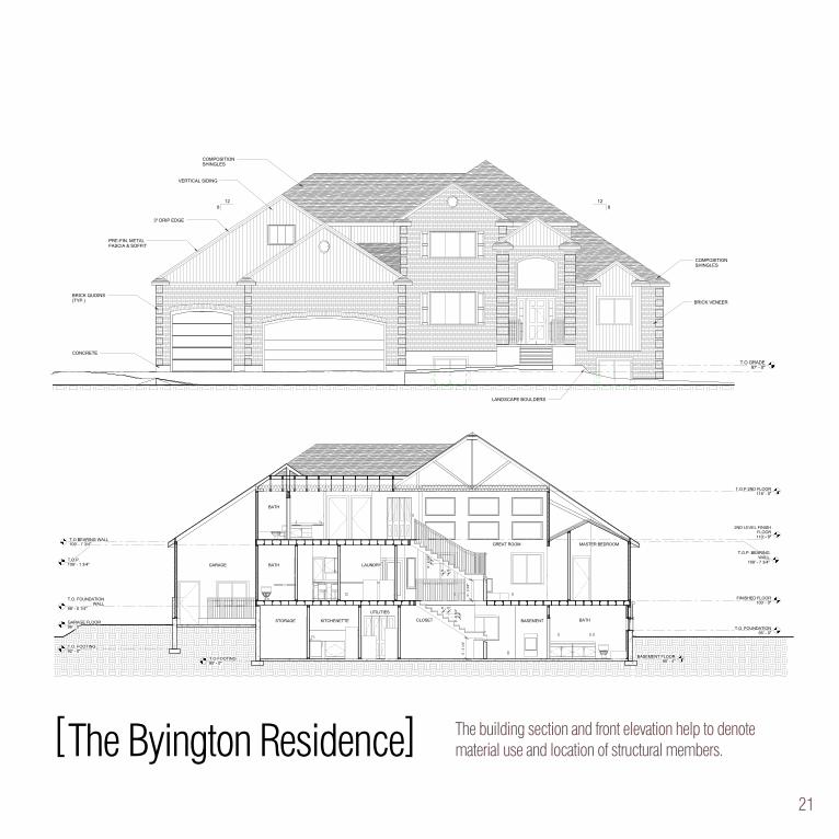
The building section and front elevation help to denote material use and location of structural members.
T.O. GRADE96' - 0"
T.O GRADE97' - 0"
8
BRICK VENEER
COMPOSITIONSHINGLES
VERTICAL SIDING
CONCRETE
128
12
COMPOSITIONSHINGLES
LANDSCAPE BOULDERS
3" DRIP EDGE
BRICK QUOINS(TYP.)
PRE-FIN. METALFASCIA & SOFFIT
T.O. GRADE96' - 0"
SITE GRADE94' - 0"
VERTICAL SIDING
CONCRETE
812
812PRE. FIN. METAL
FASCIA & SOFFIT
COMPOSITIONSHINGLES
3" DRIP EDGE
Scale
Project number
Date
Drawn by
Checked by
1/4" = 1'-0"
A-104
EXTERIORELEVATIONS
1
THE BYINGTONFAMILY RESIDENCE
07/27/2009GEOFF NIELSONSCOTT NIELSON
1/4" = 1'-0"
FRONT ELEVATION
1/4" = 1'-0"
BACK ELEVATION
A-P
DF S
plit DE
MO
: Purchase from
ww
w.A
-PD
F.com to rem
ove the waterm
ark
2ND LEVEL FINISHFLOOR110' - 0"
T.O.P 2ND FLOOR118' - 0"
BASEMENT FLOOR90' - 4"
T.O. FOUNDATION95' - 0"
FINISHED FLOOR100' - 0"
GARAGE FLOOR96' - 0"
3' -
5 1/
4"3'
- 3
3/4"
T.O.P.109' - 1 3/4"
T.O BEARING WALL109' - 7 3/4"
T.O. FOUNDATIONWALL
99' - 0 1/4"
T.O.P. BEARINGWALL
109' - 7 3/4"
T.O. FOOTING92' - 0"
T.O FOOTING90' - 0"
0' -
6 3/
4"
0' - 11"
0' -
6 3/
4"
0' - 11"
GARAGE BATH
BATHSTORAGE KITCHENETTE
UTILITIES
CLOSET BASEMENT
GREAT ROOM MASTER BEDROOM
LAUNDRY
BATH
Scale
Project number
Date
Drawn by
Checked by
1/4" = 1'-0"
A-106
CROSS SECTION
1
THE BYINGTONFAMILY RESIDENCE
07/27/2009GEOFF NIELSONSCOTT NIELSON
1/4" = 1'-0"
BUILDING SECTION
ATTIC VENTILATIONPROVIDE ATTIC VENTILATION
EQUAL TO 1/300TH OF THE ATTICSQUARE FOOTAGE. oNE HALF OF
THAT AREA SHALL BE AT THESOFFIT AND ONE HALF NEAR THE
RIDGE W/ GRAVITY VENTS
STRUCTURALNUMBER NOTES
1 TRUSS DESIGN CONFIGURATION & SPACING TO BEDETERMINED BY TRUSS MFR
2 FLOOR SYSTEMS ARE BASED ON A 9 1/2" DEEP "I" JOISTS.EXACT DEPTHS AND SPACINGS ARE TO BE DETERMINED BYFLOOR SYSTEM SUPPLIER. EXACT FLOOR ELEVATIONS MAYVARY SLIGHTLY DEPENDING ON PRODUCT USED
3 SEE STRUCTURAL ENGINEERS DOCUMENTATION FORBRACED PANEL LOCATIONS, ANCHORS, HOLD DOWNS, ETC.
A-P
DF S
plit DE
MO
: Purchase from
ww
w.A
-PD
F.com to rem
ove the waterm
ark
[The Byington Residence]

Geoff Nielson


![Semantics with Applications [1ex] @let@token 1. Introductionhrni/SWA/SwA_presentations/SwA-1... · Semantics with Applications 1. Introduction Hanne Riis Nielson, Flemming Nielson](https://img.pdfslide.us/doc/110x75/5f2df5417d7c6248976660ab/semantics-with-applications-1ex-lettoken-1-hrniswaswapresentationsswa-1.jpg)