Embed Size (px)
Citation preview
CDR
Geocentric Heliogyro Operational Solar-sail Technology (GHOST)
Nicholas Busbey Mark Dolezal Casey Myers Lauren Persons
Emily Proano Megan Scheele Taylor Smith Karynna Tuan
1
Presentation Sections
bullPurpose and Objectives
bullGHOST Design Solution
bullCritical Project Elements
bullRequirement Satisfaction
bullRemaining Risks
bullVerification and Validation of Design
bullProject Planning
2
2
Heliogyro Background
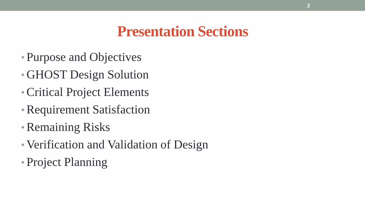
bull Solar-sails use momentum transfer for propellant-less propulsion
bull Heliogyro sails (blades) are gyroscopically stiffened in place of structural support
bull Greatly reduces mass of satellite simple design scales to a much larger conventional solar sail
bull Blades must be extremely long to provide adequate area for meaningful acceleration
bull Presents a challenge to provide storage and deployment of sails
bull No ground demonstrations of systems capable of packaging and deploying full scale blades currently exist
3
ldquoTraditionalrdquo Solar Sail
Satellite bus
Solar Sail Blades
rotation
rotation
Heliogyro Solar Sail
3 Purpose and Objectives
Objective Statement
GHOST will design build and test a heliogyro solar sail deployment and
pitching mechanism packaged into a CubeSat of up to 12U and capable of
deploying and pitching adequately sized solar sail blades to provide a
characteristic acceleration of 01 mms2
bull Design a storage system for two blades
bull Build and test deployment mechanism for one solar sail
bull Build and test coordinated pitching mechanism for two solar blades using blade-
equivalent masses
4 Purpose and Objectives
Specific Objectives
bull Blades will deploy using motors aided by centrifugal tension
bull Blades will deploy at a controlled rate of 1 ndash 10 cms
bull Verified by deployment test in 1G environment
bull Blade roots demonstrate coordinated pitching motion of 180ordm (plusmn 90ordm)
bull Verified by pitching test in 1G envornment
bull Entire structure must be stowable within a 6U CubeSat
bull System limited to 10 W of power
bull Must show that structure can survive launch
5 Purpose and Objectives
Basics of CubeSat Design Blade Modules Center Module
Front View
Top View
Blade
Launch Tabs
Tip Mass
Blade
Deployment
Motor
Brackets to Secure Blade
Hub to Attach
Center and
Blade Modules
Tip Mass
Brackets to Attach
Walls Together
Front View
Top View Pitching Motors
and Encoders
Motor Drivers
and Electronics
Board
Launch Locks
6 Purpose and Objectives
Deployment and Pitching
Pitching the Blade Modules Deploying the Blades
7 Purpose and Objectives
Blade
Tip Mass
30 Controlled deployment of sails via motors
31 Suspend undeployed blade in 1G
32 Initiate deployment mechanism
33 Controlled sail deployment using motors
50 Pitch solar sail roots
51 Establish connection with
pitching mechanism
52 Send appropriate pitch command
53 Measure resulting pitch angle
531 Record actual pitch angle and
compare to expected pitch angle
532 Ensure both actuators are capable
of generating synchronized ndash
collective frac12 P and 1P cyclic root
pitch deflections
Concept of Operations (ConOps)
8 Purpose and Objectives
Rideshare Opportunity
Spacecraft Adapter (SA)
6U Heliogyro CubeSat has an opportunity to be a
Secondary Payload on Exploration Mission 1 (EM-1) 1st Launch of NASArsquos Space
Launch System (SLS) Launch
Vehicle inserting the unmanned
Orion Multi-Purpose Crew
Vehicle (MPCV) into Lunar Orbit
bull TBA ~ Dec 2017
Orion SLS Configuration
Orion Crew Module
9
See Appendix for CSD Configuration on SLS
Purpose and Objectives
SLS Launch
Lunar Flyby Separation
of Orion from ICPS
ICPS Disposal Burn
Injection of Secondary Payloads GHOST
Low C3 Heliocentric Trajectory
EM-1 Timeline
Moon
Earth
10
Orbit Transfer Capability
bull Heliogyro architecture
bull A component of thrust can be vectored into the
in-plane (119878 ) direction of a solar blade
bull Allows for efficient orbit raising without having
to precess the momentum vector like a
conventional solar sail
Sunlight
Ω
θ = 35deg
θ = -35deg
θ = 0deg
Orbit Raising Pitch
Orientation Profile
θ = 0deg
11 Purpose and Objectives
119865 119904
119865 119899119890119905 119865 119882
ℎ ℎ119901119903119890119888119890119904119904
119878
119877
119882
Cyclic 1P Pitch Profile Single Blade In-Plane Thrust vs Blade Pitch
Presentation Sections
bullPurpose and Objectives
bullGHOST Design Solution
bullCritical Project Elements
bullRequirement Satisfaction
bullRemaining Risks
bullVerification and Validation of Design
bullProject Planning
12
Functional Block Diagram 13 GHOST Design Solution
Baseline Design
Blade
Blade
Deployment
(Stepper) Motor
Blade Module
Center Module
Pitching
(Servo) Motor
8 cm
8 cm
13 cm
frac12 cm
frac12 cm
Electronics Board
Stepper Motor Drivers
Servo Motor Drivers
Launch
Tabs
bull Constrained by 6U design
bull 8 cm ndash 13 cm ndash 8 cm with frac12 cm clearance
bull Deployment modules rotate plusmn 90 to pitch
bull Each Blade Module holds rolled sail and Sanyo
Stepper motor
bull Central Pitch Module holds 2 servo-motorsencoders
4 motor drivers and 1 electronics board
bullExtra 2U for power source communication
systems and scientific instruments
bull Launch Tabs for CSD deployment
14 GHOST Design Solution
Baseline Design Central Pitch Module 1 Servomotor stabilized to outer wall
1Pitching Axle fed through hole in wall
2Driven by servo for consistent low-vibration inputs
3Powered by 5V battery
2 PIC receives input and interfaces with drivers
3 18 in flat aluminum walls
1Corner brackets to resist loadsresist vibration
4 Launch locks to reduce vibrational forces during launch
Servo Motors
Pitching Axle
Encoders
Launch Locks
Corner Brackets
Servo Motor Drivers
Stepper Motor Drivers
Electronics Board
with PIC Launch
Tabs
15 GHOST Design Solution
Baseline Design Blade Deployment Modules
bull Hub with set-screws to stabilize
and hold deployment axle
bull Service loop to allow full plusmn90
degree motion
bull S-brackets on sides to stabilize
deployment reel
bull Non-motor side utilizes ball bearing
to assist with low-friction
deployment
bull Axle stabilized by motor and
ball bearing
bull Tip mass of sail held on a C-
bracket on the outer side of the
module
bull Held still by holding torque C-
bracket and stainless steel tape
measure material
Blade
Blade
Hub
Service
Loop
S-brackets Ball Bearing
C-brackets
16 GHOST Design Solution
Micro-
Controller
Stepper
Driver 2 Stepper
Motor 1
Servo
Driver 1
Servo 1
Encoder
DAC
Baseline Design Electronic System
Stepper
Driver 1 Stepper
Motor 2
Servo
Driver 2
Servo 2
Encoder
Hall Sensor Hall Sensor
17 GHOST Design Solution
Initialization CheckState( )
Emergency Stop bull Block DeployPitch
bull Wait for State 2
bull StorePlace( )
Restart bull Check two
previous states
bull Adapt Algorithm( )
Deployment bull CheckDeployed( )
bull Deploy( )
1
2
4
Communications
ISR( )
N-1 = 1
N-1 = 1 N-2 = 3
N-1
= 1
N-2
= 4
N-1 = 1 N-2 = 6
3
6
Pitching bull CheckDeployed( )
bull Pitch( )
SpinUp bull TapeDeploy()
bull Pitch( )
bull EndSpin()
5
Idle bull Idle( )
Emergency Stop
Restart
Deployment
Pitching
SpinUp
LEGEND
Baseline Design Software System
18 GHOST Design Solution
Mass Budget
Attribute Mass
[kg]
Mechanical 218
Electrical 0429
Structural 0265
Total 288
Total Limit 40
Available 112
Mechanical CubeSat plates axles aluminized mylar
stiff steel tip
Electrical Servomotors stepper motors motor drivers
wiring
Structural Brackets braces stabilizers hubs screws
bull If mass goes over-budget triangles can be cut into non-load bearing sections of the CubeSat
bull Reduces mass without compromising structural integrity
bull Slight over-estimation does not account for holes for screwsaxles
19 GHOST Design Solution
Power Budget Individual Components
Power Usage Number per
System
Supply Current
per System (A)
Supply
Voltage (V)
Power Subtotal
(maximum) (W)
Mission Phase
Launch Locks 2 -- 28 15 1
PIC18F87K22 1 001 5 005 1 2 3 4
Sanyo Stepper Motor 2 04 35 14 1 2 3 4
Driver DRV8834 2 1phase 5 5 1 2 3 4
Servomotor
FAULHABER 2036
2 02 5 10 2 4
Servomotor Driver 2 01 5 05 24
Encoder AU-
ZSD1000A
2 004 5
095
2 4
Mission Phase Description Power Budget Total Power Used
Pre-deployment (1) Stepper motor holds Launch Locks initiate unlock gt 10 W 2215 W
Initial Spin-Up (2) Stepper releases 5m stepper holds while pitching 10 W 91 W
Deployment (3) Stepper motor rotates to deploy blade 10 W 715 W
Pitch and Hold (4) Servomotor pitches blade root Stepper motor holds 10 W 91 W
20 GHOST Design Solution
Presentation Sections
bullPurpose and Objectives
bullGHOST Design Solution
bullCritical Project Elements
bullRequirement Satisfaction
bullRemaining Risks
bullVerification and Validation of Design
bullProject Planning
21
21
Critical Project Elements
bull Mechanical
bull Blade Deployment
bull Blade Reel Module can store a sufficiently sized solar sail blade
bull Sized such that will produce a minimum characteristic acceleration of 01 mms^2
bull Motor fits in Blade Reel Module and is capable of a controlled deployment rate of 1 to 10 cms
bull Pitch Actuation
bull Motor can actuate the Blade Reel Module plusmn 90deg
bull Central Module allows for a minimum of 2U (200 cm^3) storage for COMM EPS and scientific payload considerations
bull Structural Integrity
bull Structure can handle shear and tensile stresses present in space and 1G environment
bull Mitigates vibration of external modules on pitch axle and motor
bull Mass amp Volume Budgets
bull Mass and Volume limited by 6 kg and 6U (1 kgU)
22 CPEs
Critical Project Elements
bull Electrical bull MicrocontrollerDriverMotor Connection
bull Functional and wiring sufficiently sized to carry necessary current
bull Inter-module service loop connection
bull Thermal Considerations bull Pitch motor and electronics are sufficiently insulated andor heated by electrical coils
bull Electrical heat dissipation does not overheat internal components
bull Power Budget bull Power usage never exceeds 10 W
bull Software bull Algorithms
bull Integrated with electronics bull Language compatible with microcontroller
bull Capable of producing relevant pitch profiles to be used by pitch motor
bull Control initial deployment deployment rate and confirm deployment status
bull Memory Concerns bull Bus has necessary memory storage on board
23 CPEs
Critical Project Elements
bull Space Concerns
bull Launch Vibrations amp Survivability
bull Structural integrity uncompromised due to launch conditions
bull Launch Locks installed for launch vibration mitigation between external Blade Reel Modules and Internal
Central Module
bull Launch Lock design for support of sail blade tip
bull Canisterized Satellite Dispenser (CSD)
bull CubeSat meets specifications for use in dispenser
bull Initial Spin-Up
bull CubeSat induces rotation of its own accord
bull Use of stainless-steel reinforced sail material at blade tip
24 CPEs
Critical Project Elements
bull Manufacturing and Assembly bull Order of Manufacturing
bull Construction from outside-in
bull Wall Construction bull Thickness sufficient for structural needs and use of fasteners
bull Solar Sail bull Attachment to deployment axle in Blade Reel Module
bull Bonding of stainless-steel supports to sail material
bull Pitching Axle bull Connection between pitch motor and external Blade Reel Module
bull Satisfies tensile and shear stress concerns
bull Minimizes vibration between interfaces
bull Bearings
bull CSD Tabs bull Tabs implemented into construction to allow use in satellite dispenser
25 CPEs
Presentation Sections
bull Purpose and Objectives
bull GHOST Design Solution
bull Critical Project Elements
bull Requirement Satisfaction
bull Controlled Deployment Rate
bull Pitching
bull Survive Launch
bull ElectronicSoftware Integration
bull Manufacturing the CubeSat
bull Summary
bull Remaining Risks
bull Verification and Validation of Design
bull Project Planning
26
Initial Spin-Up
bull Problem Initially deploy solar sail straight without aid in centripetal forces
bull Hardened stainless-steel support attached along middle of last 5 m of Sail Membrane and acts as a ldquotape-measurerdquo
bull Properties of ldquotape measurerdquo bull Dim 5m x 2cm x 127μm
bull ρ = 7860 kgm3
bull m = 998 g
bull A maximum torque of 0147 mNmiddotm required by deployment motor
bull Conditions to reach Ω = 1 RPM
bull 120579119901119894119905119888ℎ = 35deg
bull ∆119905119904119901119894119899 119906119901= 184 days
Solar Blade
Steel Spine
CubeSat
Ω = 1 RPM
Rinitial = 5 m
F = 35 μN
27 Controlled Deployment Rate
Centripetal Acceleration
Deployment
Length
(m)
Centripetal
Acceleration
(ms2)
Sail
Mass
(kg)
Centripetal
Force (N)
5 0055 0014 74times10-5
100 11 0080 0088
200 22 015 033
300 33 022 072
400 44 029 127
500 55 036 197
545 58 038 217
28
Rotation Rate Ω = 1 RPM
Orbital Trajectory
Vtip
Ω
Controlled Deployment Rate
Fg
Fc
Fg is negligible
Space to Earth Comparison
29
CubeSat rotating at 1 RPM rarr centripetal acceleration rarr centrifugal tension
Blade is fully deployed rarr maximum centrifugal tension
Simulate same centrifugal tension the blade would experience in space
Total mass of 36 g used in the deployment test
mTotalSpace = 3775 g
F = 217 N
mTotalEarth = 119865
119892 = 2215 g
The holding torque of the motor used must be able to withstand this force
τ = r times F τ = 0011 Nm
Space Application
Motor
CubeSat
rotating at 1
RPM
Blade Tip mass
F
Top View
Tip mass trajectory
mTM = 2070 g
F = mg
Ground Deployment
r
Mounted to Table Side View
Tip
mass
Motor
Blade
Front View
MotorBus
Interface
Controlled Deployment Rate
Deployment Parts List Electronics Part Voltage (V) Current (A) Interface Dimensions (mm) Cost ($)
Sanyo Stepper Motor 35 03 Input 4 (bipolar) 42times42times11 60
DRV8834 Low-Voltage
Stepper Motor Driver
25-108 05phase Output 4
Input 8 (7 IO 1 CCP)
Power 2 (motor and logic)
Ground 2 (motor and logic)
15times20 10
30 Controlled Deployment Rate
Stepper Motor Stepper Motor Driver
Software Prototype
Deployment
Algorithm
bull Written in MATLAB to prove concept of deployment
bull Need to maintain constant deployment rate
Time Step Passes
Find Rotations Made in Time Step
Calculate Length Deployed
Find new Diameter and
Circumference
Calculate new Rotation Rate
Set Initial Diameter
and Circumference
Calculate Rotation
Rate
31 Controlled Deployment Rate
Presentation Sections
bull Purpose and Objectives
bull GHOST Design Solution
bull Critical Project Elements
bull Requirement Satisfaction
bull Controlled Deployment Rate
bull Pitching
bull Survive Launch
bull ElectronicSoftware Integration
bull Manufacturing the CubeSat
bull Summary
bull Remaining Risks
bull Verification and Validation of Design
bull Project Planning
32
The Need for plusmn 90deg Range of Pitch
Blade
Pitch θ
Condition (Profile Description)
0deg Max Thrust (Collective Blade Surface
Normal to Sunlight)
plusmn 35deg Max Torque (Collective) or Max In-Plane
Thrust (1P Cyclic)
plusmn 90deg No Thrust (Collective Blades Edge on to
Solar Wind)
Full 180deg range of motion for blade pitch necessary for spacecraft to have full capabilities of
controlling the thrust vector See Appendix for further information
33 Pitching
Pitching Parts List Electronics
Part Voltage (V) Current (A) Interface Dimensions (mm) Cost ($)
FAULHABER 2036
BLDC Motor
5 02 Input 3 phase
Sensors 3 HALL
Power 1
36times20 (diameter) 230
Atmel ATA6832-DK
Brushless DC Motor
Controller
5 01 Output 3 phase
Input 1 Serial 2 IO
45times45 208
2 Channel IE2-1024
Encoder
5 04 Output 4 I0
Power 1
165times15 (diameter) 225
34
2036 BLDC Motor
Pitching
Servo Controller
bull Bypass LIN input for direct interface with potentiometer
(Serial input use DAC from microcontroller)
35 Pitching
Pitching Software
Pitch Profile Command Sent
Find corresponding
sinusoid equation for pitching
Command servo to turn to angle in
pitching sinusoid
Compare to Encoder Angle
Given a pitch profile the software will
bull Find the corresponding sinusoid command for the
servos
bull Step through those angles over the time period
bull Compare commanded angle to encoder feedback
bull Adjust for accuracy
Pitching 36
Presentation Sections
bull Purpose and Objectives
bull GHOST Design Solution
bull Critical Project Elements
bull Requirement Satisfaction
bull Controlled Deployment Rate
bull Pitching
bull Survive Launch
bull ElectronicSoftware Integration
bull Manufacturing the CubeSat
bull Summary
bull Remaining Risks
bull Verification and Validation of Design
bull Project Planning
37
Canisterized Satellite Dispenser CSD
bull 6U fits into CSD during launch
bull Gives extra clearance on each side bull Allows for locking mechanism outside the 6U
bull Available with Alum 6061
bull Pushed into orbit on ldquoTabrdquo structure bull Additional tabs added below CubeSat base
bull Able to separate tabs for each separate section
38 Survive Launch
Structural Integrity of Pitching Axle and Selection of
Material
bull Aluminum 6061
bull Lightweight (density of 27gcc)
bull Very strong
bull Inexpensive
bull Pitching Axle ndash rod 1 cm in diameter
bull If made of Aluminum 6061
bull Can withstand shear force of 162 kN (~3600 lbs)
bull Does not take into account ability of motor to withstand torque
F (from Solar
Sail)
τ
39 Survive Launch
Pitching Axle
Launch Locks
bull Sierra Nevada SP-5025 pin puller
bull 350 lbf (1500 N) of shear load
bull Powered by a single timed power pulse to one of
the redundant heater circuits
bull SP -5025 greatly exceeds budget so manual
screw and bolt sized appropriately simulate
launch locks in the prototype
40
SP-5025
SP-5025
Deployed
Stowed
Simulated
Launch Locks
Survive Launch
Credit to SNC
Secure Blade Tip Mass
bull C-brackets attached to exterior walls stabilize tip mass vertically and horizontally
bull Cylindrical tip mass fits securely in brackets on both sides
bull Holding torque of stepper motor and tape-measure material holds tip mass in towards rolled blade
bull Within outer limit required by CSD
41
16 cm
075 cm 2 cm
Survive Launch
Presentation Sections
bull Purpose and Objectives
bull GHOST Design Solution
bull Critical Project Elements
bull Requirement Satisfaction
bull Controlled Deployment Rate
bull Pitching
bull Survive Launch
bull ElectronicsSoftware Integration
bull Manufacturing the CubeSat
bull Summary
bull Remaining Risks
bull Verification and Validation of Design
bull Project Planning
42
Service Loop
Power and input wires needed in for stepper
motor in deployment module
bull 4 12A rated wires AWG 21 D = 073 mm
bull Full loop around pitching axle to allow for
plusmn90deg rotational freedom
bull 1 cm diameter hole through each plate
bull Current must run throughout launch to
keep holding torque
bull Need not worry about freezing later in mission
Wires (red) exit opening in wall loops around
pitching axle enters opening in opposite wall
43 ElectronicsSoftware Integration
Electrical Block Diagram
Micro-
controller
35 V Supply
Stepper
Driver
Stepper
Motor
H4
H5
H3
H6
Key IO
CCP
Power
Serial
GND
Sensor
VDD
M0
M1
ENABLE
CONFIG
GND
DIR
STEP
E0
E2
B2
B1
A1
A2
VMOT GND VDD
5 V Supply
GND
Servo
Driver 1
Servo 1 TX RX
P G A B C
5V GND U V W Servo
Driver 2
Servo 2
P G A B C
5V GND C2 C3 C4 U V W
Encoder
J2 J3 J4 J5 J6 J7
VDC G
C0
(Speed Set)
C0
(Speed Set)
RS 232
DAC
A B C
Encoder VDC G A B C
B5 B4
A3
A7
B7
B6
D4
D3
D4 D3
C2 C3 C4
VoutA
VoutB
SCLK CS
DIN
GND
Tin Rout Vin GND
VDD
A4
SLEEP
FAULT H0
E1
44 ElectronicsSoftware Integration
Microcontroller PIC18F87K22
Board Requirements
bull Serial output for communication with computer
and servomotor controller
bullDAC used for servomotor communication
bull I0 ports for stepper driver interface
bull CCP port for stepper driver interface
bull Header pins for the encoder interface
Total
18 IO
1 CCP
1 TXRX
bull Would need more IO and CCP ports for a second
stepper motor driver
bull Unused ports 37 IO and 10 CCPECCP
ElectronicsSoftware Integration
PCB Design
bull 2 Layer Board
bull FR4 material
bull 1 oz Copper traces
bull Estimated Dimension = 5times5 cm
bull (See Appendix for Electrical Schematic)
EasyPIC PRO
v7 Pinout
80 Pin Development
Board
ElectronicsSoftware Integration
Incompatible Industrial Boards
Presentation Sections
bull Purpose and Objectives
bull GHOST Design Solution
bull Critical Project Elements
bull Requirement Satisfaction
bull Controlled Deployment Rate
bull Pitching
bull Survive Launch
bull ElectronicsSoftware Integration
bull Manufacturing the CubeSat
bull Summary
bull Remaining Risks
bull Verification and Validation of Design
bull Project Planning
47
Manufacturing In-House vs Purchasing
48
Part In-House Purchase Details
CubeSat walls Aluminum will be purchased with correct thickness and
manufactured to needed dimensions
Blade and pitching axle Axles can be cut down to needed length
Corner brackets Brackets can be altered to fit needed dimensions
S-brackets and C-brackets Will have to be machined to fit strict dimensions
Tip mass Tip mass can be cut down to needed length
Tape-measure material Purchased from McMaster-Carr
Solar sail blade material Blade material is provided for free by NASA LaRC
Launch Locks Launch locks we will use are a screw and bolt
Launch Tabs for CSD Tabs must meet strict dimensions to fit into CSD from
Planetary Systems Corporation
Hub to attach pitching axle to blade module Will have to be machined to meet needed dimensions
Screwsnutsbolts All can be purchased in various sizes and lengths
Motorsencoders and motor drivers All purchased to meet necessary requirements
Electronics board Will have to be made to accommodate needed electronics
Stabilizers to hold pitching motors Will have to be machined to properly fit around motors
Manufacturing the CubeSat
Assembly Procedure
49 Manufacturing the CubeSat
Bonding Mylar to Spool and Stiff Material
bull Loctite Super Glue Professional
bull Shear strength of 01 Nmm2
bull Cross-Sectional Area = 6575 mm2
bull Shear Stress = 33e-4 Nmm2
bull Blade will retain 4 rolls around axle at
final length
bull Loctite to bond stainless steel stiff
material to Mylar and to spool
F = mg = 217 N
Motor
Blade frac14 of roll glued
50 Manufacturing the CubeSat
Fixing Deployment Motor to S-Bracket
51
bull Deployment stepper motor is attached to S-bracket
bull S-bracket stabilized to back of blade deployment
module and vertical CubeSat walls
bull Motor is capable of being screwed directly to S-bracket
bull S-bracket has thickness of 18 inch
Holes for screws to
stabilize S-bracket
Hole for motor shaft
or press-fit ball
bearing to attach to
blade axle
Holes to screw motor
to S-bracket
Manufacturing the CubeSat
Pitching Axle Interfaces
bull Pitching axle to motor axle
bull Motor axle (smaller) fits into pitching
axle (larger) using set-screws
bull Pitching Axle to Blade Reel
Module
bull Axle fixed by set screws inside a hub
52
Pitching Axle
Hub
Motor Axle
4 Set Screws
Manufacturing the CubeSat
Presentation Sections
bull Purpose and Objectives
bull GHOST design solution
bull Critical Project Elements
bull Requirement Satisfaction
bull Controlled Deployment Rate
bull Pitching
bull Survive Launch
bull ElectronicSoftware Integration
bull Manufacturing the CubeSat
bull Summary
bull Remaining Risks and Mitigations
bull Verification and Validation of Design
bull Schedule and remaining work
53
Requirements Satisfaction
Aspect Requirement GHOST Specification
Mass 1 kgU 288 kg
Volume lt= 12U 6U
Life Span 4 months Greater than 4 months
Space Applicable
While design does not need to be
space worthy it should be applicable
to being used in space
All components are picked for
realistic use in space with minimal
cost parts and increased life span
54 Summary
Requirements Satisfaction
Aspect Requirement GHOST Specification
Characteristic Acceleration ac ge 01 mms2 ac = 03868 mms2
Sail Aspect Ratio AR ge 1001 AR = 38931
Sail Deployment Speed 1 cms le 10cms ~5 cms
Pitching Range Ability to pitch blades plusmn 90deg Ability to pitch blades plusmn 90deg
Pitching Coordination Multiple blade coordination when
pitching
Can pitch both blades at once either to
same angle or opposite angles
55 Summary
Presentation Sections
bullPurpose and Objectives
bullGHOST Design Solution
bullCritical Project Elements
bullRequirement Satisfaction
bullRemaining Risks
bullVerification and Validation of Design
bullProject Planning
56
Design Risks
Severity
Likelihood Marginal Major
Often Pitch angle error root not
following tip
Occasional Power loss COMM loss
Structural survivability
pitching motor failure
Improbable Small tear in Mylar Deploy too fast stowage
and deployment of Mylar
Axle failure
launch fail
space dust
deployment motor failure
57 Remaining Risks
Logistical Risks
Severity
Likelihood Minor Marginal Major
Often Parts delayed due to US
Postal Service
Occasional Structural consultation
unavailable
Ball vibrations test is not
available machine parts
not done on schedule
Government shutdown and
we canrsquot get Mylar or help
from NASA
Improbable No time for pitching test
High Bay in Fleming is
unavailable motors donrsquot
show up
58 Remaining Risks
Financial Risks
Severity
Likelihood Minor Marginal Major
Often Repurchase parts
Occasional Motor breaks Price of shake table
Improbable Hyper inflation
59 Remaining Risks
Presentation Sections
bullPurpose and Objectives
bullGHOST Design Solution
bullCritical Project Elements
bullRequirement Satisfaction
bullRemaining Risks
bullVerification and Validation of Design
bullProject Planning
60
Deployment System
Validate that the blade is deployed at a constant rate of 1-10 cms in a high bay
room
Verify that the motor can deploy at constant rate
Verify with test that the deployment system does not use more than the maximum power available of 10W
Validate that the blade can successfully deploy a blade with tape measure
material at a constant rate along ground
Verify with demonstration that the tape measure material can extend length of
blade
Verification and Validation
Verification and Validation
61
Blade Deployment Testing Information
bull Location Prof Frewrsquos High Bay Lab
bull Scheduled MarchApril with late night access to avoid
scheduling conflicts
bull Measurement Tape measure for distance and video
camera for time
bull Power Delivered 6253A Dual DC Power Supply
delivers 0-20 V and 0-3A
Tape measure
marking
distance up
wall
Kinematic Model
bull Torque from motor drives a constant velocity deployment
120591119898119900119905119900119903 = 120591119903119900119897119897 + 120591119901119906119904ℎ119894119899119892 119879119872 minus 120591119892119903119886119907119894119905119910 119879119872
120591119903119900119897119897 =119889119868119903119900119897119897
119889119905120596119903119900119897119897 + 119868119903119900119897119897
119889120596119903119900119897119897
119889119905
120591119901119906119904ℎ119894119899119892 119879119872 =119889119898119890119909119905
119889119905119903119903119900119897119897119907 + 119898119890119909119905
119889119903119903119900119897119897
119889119905119907
120591119892119903119886119907119894119905119910 119879119872 = 119898119890119909119905119903119903119900119897119897119892 bull 120649119945119952119949119941119946119951119944 = 120782 120782120790120787 N∙m 120649119950119952119941119942119949119950119938119961 = 120782 120782120782120789 N∙m
Power Supply
Verification and Validation
CubeSat Wire
62
Pitching System
Validate that the blade reel modules experience coordinated pitching
Verify that one blade reel module experiences periodic
motion
Verify that the blade reel module rotates to 0deg upon
initialization
Verify that the blade pitches to a given command
angle
Verify that the motorencoder system does not exceed power
available
Verification and Validation
Verification and Validation
63
Verify Pitching Angle Experiment Equipment and Specs
bull Use R60D RVIT (Rotary Variable Inductance Transducer) sensor to measure angles attaches to pin (red) in line with pitching axis bull Measures ranges of plusmn60deg rotation
bull Input Voltage = plusmn15 V
bull Output Voltage = plusmn75 V
bull Resolution = 0125 Vdeg
bull 119891119898119886119909 = 20 Hz
bull Use AD524 Precision Amplifier Instrumentation for signal conditioning bull Input Voltage plusmn10 V
bull Output Voltage plusmn10V
bull Requires Supply Voltage plusmn15
bull Use NI 9201 bull Input Voltage plusmn10 V
bull Has a USB output that can connect to a computer where vi program records
Experiment Set-Up
R60D RVIT
AD524
NI 9201 PC via USB
Verification and Validation 64
Verify Periodic Motion Experiment
bull Using the R60D RVIT set-up to measure deflection angles
bull With data of the angle deflection 120579 angular velocity 120596 and angular acceleration 120572 can be measured bull Motor restriction 120591119898119886119909 = 032 Nmiddotm
bull Model restriction 120596119898119886119909 = Ω2 if Ω = 2rpm 120596119898119886119909 = 02094 rads
Validation Model
bull R60D RVIT measures plusmn60deg deflection angles bull Critical condition blade reel module pitches plusmn90deg Ω=2rpm
bull 120572119888 = 00172 rads2 and 120596119898 = 0164 rads thus 120591119898 = 0083 mNmiddotm (119868119898119900119889 = 00048 kgmiddotm2)
120579 119905 120596 119905 120572 119905
Verification and Validation 65
Verification and Validation
Structural System
Validate that the final design can survive launch by using a shake
table
Verify the structural integrity by demonstrating that all stationary parts are
static
Verification and Validation 66
Trade Study FEM vs Vibration Table
Cost Time Experience
Similar to
Actual
Launch
Guaranteed Can
Do Total
FEM 4 1 1 3 4 215
Vibration
Table 2 3 4 4 2 32
Weight () 5 30 25 20 20 100
67 Verification and Validation
See Appendix for Full Trade Study
Validate Structural Stability
bull Will use a shaker table from Ball Aerospace
bull Cost = $250hr
bull Schedule Time to be determined in April
bull Specifications Peak vibration occurs with 34g at
frequency of 16 Hz (Saturn V)
bull Will be verified by examining the structural integrity
of the manufacturing
Verification and Validation 68
CubeSat
Shake Table
Presentation Sections
bullPurpose and Objectives
bullGHOST Design Solution
bullCritical Project Elements
bullRequirement Satisfaction
bullRemaining Risks
bullVerification and Validation of Design
bullProject Planning
69
Organizational Chart
Mark
Dolezal
Emily
Proano
Lauren
Persons
Casey
Myers
Nicholas
Busbey
Taylor
Smith
Karynna
Tuan
Megan
Scheele
Project
Manager
Software
Lead
Electrical
Lead
Systems Test and
Safety
Manufacturing
Lead Mechanics
Lead
CFO and
Materials
Lead
Organizing
team
meetings
Supporting
other leads
Non CPE
Tasks
Deployment
Control
Pitching
Control Motors and
Electronics
Power
Integrate
all system Perform
and Plan
tests
Manufacture
all in-house
parts
SolidWorks
Keep track
of financial
spending
Right
materials
are being
utilized
CubeSat
Assembly
Specific
System
Requirements
70 Project Planning
GHOST
Materials Mechanical Electrical Software Documents
Shake Table
Vibration
Analysis
Mechanical
Layout
Power Budget Pitch Control
Algorithm
Deployment
Rate Control
Algorithm SolidWorks
Model
Electrical
Wiring Layout
Thermodynamic
Analysis of
Electronic System
Mass Budget
Prototype of
CubeSat Bus
Motor
Subsystem
CDR
FFR
Spring
Schedule
Financial
Budget
Work Breakdown Structure (WBS)
Mylar from
NASA
Spin Up
Algorithm
Emergency
StopRestart System
71 Project Planning
PCB Design
Spring
Documents
113 120 127 203 210 217 224 303 310 317 324 331 407 414 421 428
MSR TRR SFR PFR
Time (date)
Purchase
motorsdrivers
Preliminary code
Electronic
integration
Test code
Electronicscode
interface
Purchase
raw materials
Manufacture frame
Assemble bus
Manufacture
remaining parts
Integrate system
Deployment test
Pitching test
Vibration test
Ta
sks
72
GHOST Spring Schedule
Project Planning
Planned Uncertainty
Key
Test Plan Test Scheduled Facility Specialized Equipment
Verify Pitch Angle 317 ITLL R60D RVIT NI 9201 AD524 Oscilloscope bench
power source
Zero Pitch Angle 317 ITLL R60D RVIT NI 9201 AD524 Oscilloscope bench
power source
Measure power used in
pitchdeployment 317 ITLL Ammeter voltmeter bench power source
Verify constant deployment 324 ITLL Firewire camera bench power source
ASEN2003BallTrackervi
Verify periodic motion 324 ITLL R60D RVIT NI 9201 AD524 Oscilloscope bench
power source
Validate tape measure ground
deployment 331 ITLL
Bench power source tape measure stop watch rollers
for tip mass
Validate coordinated pitching 331 ITLL R60D RVIT NI 9201 AD524 oscilloscope bench
power source
Validate 1g blade deployment 331-414 Prof Frew
high bay
Portable 6253A Dual DC Power Supply ladder tape
measure video camera
Validate launch ready 414 Ball Aero Shake Table
Project Planning 73
Cost Table ndash Structural Components
Part Price per
part NeededVolume Needed Total Price Supplier
Aluminum 6061 Sheet
(18rdquo thick) $ 8976 2ft times 2ft times 18 in $ 8976 The Metals Depot
Aluminum 6061 rod
(14 in diameter) $280 2 ft $280 The Metals Depot
Aluminum6061 rod
(716 in diameter) $494 2 ft $494 The Metals Depot
Steel Corner Brackets
(34rdquo times 12rdquo)
$197 4
braces 16 $788 Home Depot
Hardened 302 Stainless
Steel $3300 2 cm times 5 m times 127 microm $3300 McMaster-Carr
Total $11834
74 Project Planning
Cost Table ndash Electrical Components
Part Price per
part Needed Total Price Supplier
Sanyo Stepper Motor $ 5995 2 $11990 Pololu Electronics and Robotics
DRV8834 Low-Voltage Stepper
Motor Driver $995 2 $1990 Pololu Electronics and Robotics
FAULHABER 2036 BLDC
Servo Motor $23000 2 $46000 MicroMo Micro Motion Solutions
Atmel ATA6832-DK Brushless
DC Motor Controller $20800 2 $41600 Atmel
Encoder AU-ZSD1000A $22500 2 $45000 MicroMo Micro Motion Solutions
PIC18F87K22 Microcontroller $500 1 $500 Microchip
AD-524 Signal Converter $1767 1 $1767 Agilent
Total $148847
75 Project Planning
Questions
76
References
bull wwwloctiteproductscom
bull Vallado D A Fundamentals of Astrodynamics and Applications
bull Guerrant D Lawrence D Heaton A Earth Escape Capabilities of the Heliogyro Sail AIAA Paper
bull wwwspaceflightnowcom
bull Guerrant D HGVizGuim MATLAB Program
bull httpwwwmicromocombrushless-dc-motorsaspx
bull httpwwwfaulhabercomservletcomitmrwawservletAnzeigefremdaufruf=jaampkdid=40929ampsprachid=1amphtdigurl=n169933i95222html
bull httpwwwpololucom
bull httpasmmatwebcomsearchSpecificMaterialaspbassnum=MA6061t6
bull httpwwwruagcomthermalSpace_Thermal_HardwareMulti_Layer_Insulation
bull Helgesen Bryan Sierra Nevada Corporation
77
GyroSail Launch Configuration and Deployment Sequence
78
1 Launch configuration (6U) 2 Blade reel modules pitch to zero Fits within a 6U or 12U dispenser
3 PV arrays deploy
Other array configurations are possible
williamkwilkienasagov NASA PREDECISIONAL - FOR DISCUSSION PURPOSES ONLY
78 Appendix
GyroSail Primary Bus Systems Based on modified JPLU MichUCLACal PolyUT INSPIRE bus
williamkwilkienasagov
05U cold gas thruster ACS for detumbling
and initial spin-up
(httpwwwaustinsatnet)
05U EPS battery CampDH UHF backup
comms (U Mich) 05U DSN-compatible X-band
communications (JPL)
05U COTS star trackerimager ADC (BCT) sail
module processor (CU)
Klesh A et al 2013 ldquoINSPIRE Interplanetary NanoSpacecraft Pathfinder In Relevant Environmentrdquo Proceedings of the AIAAUSU Conference on Small Satellites Around the Corner SSC13-
XI-8 httpdigitalcommonsusuedusmallsat2013all2013127
NASA PREDECISIONAL - FOR DISCUSSION PURPOSES ONLY
79 Appendix
COMM Subsystem
bull 18 m Ka-band antennas at White
Sands New Mexico
bull Goddard Space Flight Center
Greebelt Maryland USA
supplied the Mulemba Space
Center in Angola
80 Appendix
Orion Crew
Module
6U Canisterized Satellite
Dispenser (CSD) ESPA Ring
Spacecraft
Adapter
Interim Cryogenic Propulsion
Stage (ICPS)
Secondary Payload Attachment to SLS
The SLS design is currently going through CDR An ESPA
ring is not currently in place but is mentioned in the SLS
CONOPS in order to accommodate secondary payloads
81 Appendix
Max Thrust Condition Collective 90deg pitch profile
Max thrust normal to orbital plane
(Halo orbits orbital plane rotation ie
inclination change)
82
Credit to Dan Guerrant
Appendix
Max Thrust Condition
F vs β M vs β
83
Credit to Dan Guerrant
Appendix
No Thrust Condition Collective 0deg pitch profile
Zero thrust
84
Credit to Dan Guerrant
Appendix
No Thrust Condition
F vs β M vs β
85
Credit to Dan Guerrant
Appendix
Max Torque Condition Collective 35deg pitch profile
Max torque used for spinning up sc
(opposite orientation for despinning)
86
Credit to Dan Guerrant
Appendix
Max Torque Condition
F vs β M vs β
87
Credit to Dan Guerrant
Appendix
Max In-Plane Thrust Condition Cyclic 35deg pitch profile
Max thrust in in-plane (d2) direction for orbit raising
88
Credit to Dan Guerrant
Appendix
Max In-Plane Thrust Condition
F vs β M vs β
89
Credit to Dan Guerrant
Appendix
Orbit Raising
F
90 Appendix
Thermal Space Concerns
bull Material Concerns
bull Aluminum 6061 -196 degC to 160deg C
bull Electronics Concerns
bull Typical Operating Temperature -55 to 80 degC
bull Countermeasures
bull Multi-layer Insulation AAErotherm S10-190
bull (0005 ndash 0035 Wm2K)
bull Battery operated heaters for pre-sail deployment
Multi-layer Insulation
Layer 1 1 x Outer layer
Layer 2 8 x 03 mil VDAPolyimideVDA perf
8 x Woven Polyester netting
Layer 3 1 x Outer layer
Layer 4 1 x Woven Polyester netting
91 Appendix
Rolled Up Blade Reel Calculation Optimal Sail Length 545 m ndash Sail chord of 14 cm
Max Diameter of Spool 598 cm
Diameter of Axle 05 cm
Length of Stiff Material 5 m
Dimension of Stiff Material 5 m times 2 cm times 127 microm
92 Appendix
Torque calculation
bull Note current calculated via T=kI (where T is torque I is amp k is the torque
constant specific to the motor)
T = kI
(k = 005 NmA)
93 Appendix
Servo Controller
94 Appendix
Encoder Dimensions and Interface
bull FAULHABER IE2-1024
95 Appendix
Stepper Motor Torque
96 Appendix
Motor Phases (Stepper)
97 Appendix
98 Appendix
99 Appendix
100 Appendix
101 Appendix
Microcontroller
102 Appendix
ATA6832 Phase Output Chip
103 Appendix
ATA6624 Bypassed Chip
bull Bypassed chip
on servo controller
104 Appendix
Power Budget
105 Appendix
Wire Gauge
bull Stepper Motor 26AWG (04 mm diameter)
bull Servomotor 24 AWG (051 mm diameter)
bull Encoder 24 AWG
Voltage Drop () AWG Max Gauge
001 5
01 15
1 25
5 32
NOTE Voltage drop calculated at 1A and 40 cm of wire
106
24 AWG Wire
Appendix
Trade Study ndash FEM vs Vibration Table
Factor 4 3 2 1
Cost No money 0 gt C gt $100 $100 gt C gt $300 $300 lt C
Time 0 min lt T lt 30 min 30 min lt T lt 2 hrs 2 hrs lt T lt 1 day 1day lt T
Experience Everyone has
experience
A couple people
know how to
1 person has
experience
No one has
experience
Similar To Actual
Launch Simulate real launch
Doesnrsquot have all
variables experienced
Has only a couple
similarities
No similarities to
launch
Guaranteed Can Do
Donrsquot need any
outside equipment or
help
Need outside
equipment but
guaranteed use
Need outside
equipment but own
work at higher
priority
Need outside
equipment but canrsquot
use
Scoring
107 Appendix
Weighting
Weight () Category Reasoning
5 Cost Have a lot of extra $ in the budget
30 Time Have a strict schedule but not a main focus of the
project
25 Experience If no one has experience it will take a lot of time
20 Similar to Actual Launch Needs to be like actual launch
20 Guaranteed Can Do Needs to be able to accomplish but not the most
important focus
108 Appendix
Finite Element Method (FEM)
Objectives Description ProCon
Cost No money because one of us
would do it Pro
Time A lot of time to learn and then
perform FEM Con
Experience No one in group has FEM
experience Con
Similar to Actual Launch Very similar to actual launch Pro
Guaranteed Can Do All we need is paper pen and
theory to do Pro
109 Appendix
Vibration Table
Objective Description ProCons
Cost $250hr Con
Time A hour on the table should simulate
launch Pro
Experience Donrsquot need experience to run
vibration table Pro
Similar to Actual Launch Actually putting our system through
vibration stress Pro
Guaranteed Can Do No guarantee but most likely can Con
110 Appendix
SpinUp State
1 Check value of SpinUp to see if satellite is already spun up
bull Continue if satellite is not already spun-up
2 Deploy the tape stiffened length of the blade
3 Pitch to the spin up angle
4 Wait until characteristic angular velocity is reached
5 Pitch to pre-deployment position
6 Save SpinUp as completed
Appendix 111
Deployment State
1 Check if satellite has been spun up yet
bull Continue if it has
2 Check if blades are already deployed
bull Continue if they havenrsquot
3 Run deploy algorithm until blades are fully deployed
4 Save value saying blades have been deployed
Appendix 112
Pitching State
1 Check if satellite has been spun up
bull Continue if satellite has been spun up
2 Check if blades have been deployed
bull Continue if blades have been deployed
3 Look at commanded pitch profile
4 Find correlated sinusoid command
5 Command servo to pitch angle for the time in the orbit
6 Continue until given a new pitch command
Appendix 113
Emergency Stop
1 Save which state was interrupted
2 Save last position in interrupted
state
3 Wait until Restart command is
received
1 Check two previous states to see
what is being restarted
2 Look at saved last position in
state being restarted
3 Adapt the algorithm of the state
to continue where left off
Restart
Appendix 114
Comparison with Previous Heliogyro Concepts MIT (1989) NASA (2011) GHOST
Total sail craft mass (kg) 18 84
288 (6)
Characteristic acceleration ac
(mms2) 06 10 03868 (01854)
Sail reflective area (m2) 1200 960 1526
Non-sail mass (kg) 5 5 --
Number of sail blades 8 6 2
Blade chord (m) 15 08 014
Blade length (m) 100 200 545
Rotational period (minutes) 3 3 1
Blade root stress (Pa) 8650 34000 --
Blade root allowable stress (Pa) 55 M 55 M --
Blade root tension load (N) 01 007 --
115 Appendix
Presentation Sections
bullPurpose and Objectives
bullGHOST Design Solution
bullCritical Project Elements
bullRequirement Satisfaction
bullRemaining Risks
bullVerification and Validation of Design
bullProject Planning
2
2
Heliogyro Background
bull Solar-sails use momentum transfer for propellant-less propulsion
bull Heliogyro sails (blades) are gyroscopically stiffened in place of structural support
bull Greatly reduces mass of satellite simple design scales to a much larger conventional solar sail
bull Blades must be extremely long to provide adequate area for meaningful acceleration
bull Presents a challenge to provide storage and deployment of sails
bull No ground demonstrations of systems capable of packaging and deploying full scale blades currently exist
3
ldquoTraditionalrdquo Solar Sail
Satellite bus
Solar Sail Blades
rotation
rotation
Heliogyro Solar Sail
3 Purpose and Objectives
Objective Statement
GHOST will design build and test a heliogyro solar sail deployment and
pitching mechanism packaged into a CubeSat of up to 12U and capable of
deploying and pitching adequately sized solar sail blades to provide a
characteristic acceleration of 01 mms2
bull Design a storage system for two blades
bull Build and test deployment mechanism for one solar sail
bull Build and test coordinated pitching mechanism for two solar blades using blade-
equivalent masses
4 Purpose and Objectives
Specific Objectives
bull Blades will deploy using motors aided by centrifugal tension
bull Blades will deploy at a controlled rate of 1 ndash 10 cms
bull Verified by deployment test in 1G environment
bull Blade roots demonstrate coordinated pitching motion of 180ordm (plusmn 90ordm)
bull Verified by pitching test in 1G envornment
bull Entire structure must be stowable within a 6U CubeSat
bull System limited to 10 W of power
bull Must show that structure can survive launch
5 Purpose and Objectives
Basics of CubeSat Design Blade Modules Center Module
Front View
Top View
Blade
Launch Tabs
Tip Mass
Blade
Deployment
Motor
Brackets to Secure Blade
Hub to Attach
Center and
Blade Modules
Tip Mass
Brackets to Attach
Walls Together
Front View
Top View Pitching Motors
and Encoders
Motor Drivers
and Electronics
Board
Launch Locks
6 Purpose and Objectives
Deployment and Pitching
Pitching the Blade Modules Deploying the Blades
7 Purpose and Objectives
Blade
Tip Mass
30 Controlled deployment of sails via motors
31 Suspend undeployed blade in 1G
32 Initiate deployment mechanism
33 Controlled sail deployment using motors
50 Pitch solar sail roots
51 Establish connection with
pitching mechanism
52 Send appropriate pitch command
53 Measure resulting pitch angle
531 Record actual pitch angle and
compare to expected pitch angle
532 Ensure both actuators are capable
of generating synchronized ndash
collective frac12 P and 1P cyclic root
pitch deflections
Concept of Operations (ConOps)
8 Purpose and Objectives
Rideshare Opportunity
Spacecraft Adapter (SA)
6U Heliogyro CubeSat has an opportunity to be a
Secondary Payload on Exploration Mission 1 (EM-1) 1st Launch of NASArsquos Space
Launch System (SLS) Launch
Vehicle inserting the unmanned
Orion Multi-Purpose Crew
Vehicle (MPCV) into Lunar Orbit
bull TBA ~ Dec 2017
Orion SLS Configuration
Orion Crew Module
9
See Appendix for CSD Configuration on SLS
Purpose and Objectives
SLS Launch
Lunar Flyby Separation
of Orion from ICPS
ICPS Disposal Burn
Injection of Secondary Payloads GHOST
Low C3 Heliocentric Trajectory
EM-1 Timeline
Moon
Earth
10
Orbit Transfer Capability
bull Heliogyro architecture
bull A component of thrust can be vectored into the
in-plane (119878 ) direction of a solar blade
bull Allows for efficient orbit raising without having
to precess the momentum vector like a
conventional solar sail
Sunlight
Ω
θ = 35deg
θ = -35deg
θ = 0deg
Orbit Raising Pitch
Orientation Profile
θ = 0deg
11 Purpose and Objectives
119865 119904
119865 119899119890119905 119865 119882
ℎ ℎ119901119903119890119888119890119904119904
119878
119877
119882
Cyclic 1P Pitch Profile Single Blade In-Plane Thrust vs Blade Pitch
Presentation Sections
bullPurpose and Objectives
bullGHOST Design Solution
bullCritical Project Elements
bullRequirement Satisfaction
bullRemaining Risks
bullVerification and Validation of Design
bullProject Planning
12
Functional Block Diagram 13 GHOST Design Solution
Baseline Design
Blade
Blade
Deployment
(Stepper) Motor
Blade Module
Center Module
Pitching
(Servo) Motor
8 cm
8 cm
13 cm
frac12 cm
frac12 cm
Electronics Board
Stepper Motor Drivers
Servo Motor Drivers
Launch
Tabs
bull Constrained by 6U design
bull 8 cm ndash 13 cm ndash 8 cm with frac12 cm clearance
bull Deployment modules rotate plusmn 90 to pitch
bull Each Blade Module holds rolled sail and Sanyo
Stepper motor
bull Central Pitch Module holds 2 servo-motorsencoders
4 motor drivers and 1 electronics board
bullExtra 2U for power source communication
systems and scientific instruments
bull Launch Tabs for CSD deployment
14 GHOST Design Solution
Baseline Design Central Pitch Module 1 Servomotor stabilized to outer wall
1Pitching Axle fed through hole in wall
2Driven by servo for consistent low-vibration inputs
3Powered by 5V battery
2 PIC receives input and interfaces with drivers
3 18 in flat aluminum walls
1Corner brackets to resist loadsresist vibration
4 Launch locks to reduce vibrational forces during launch
Servo Motors
Pitching Axle
Encoders
Launch Locks
Corner Brackets
Servo Motor Drivers
Stepper Motor Drivers
Electronics Board
with PIC Launch
Tabs
15 GHOST Design Solution
Baseline Design Blade Deployment Modules
bull Hub with set-screws to stabilize
and hold deployment axle
bull Service loop to allow full plusmn90
degree motion
bull S-brackets on sides to stabilize
deployment reel
bull Non-motor side utilizes ball bearing
to assist with low-friction
deployment
bull Axle stabilized by motor and
ball bearing
bull Tip mass of sail held on a C-
bracket on the outer side of the
module
bull Held still by holding torque C-
bracket and stainless steel tape
measure material
Blade
Blade
Hub
Service
Loop
S-brackets Ball Bearing
C-brackets
16 GHOST Design Solution
Micro-
Controller
Stepper
Driver 2 Stepper
Motor 1
Servo
Driver 1
Servo 1
Encoder
DAC
Baseline Design Electronic System
Stepper
Driver 1 Stepper
Motor 2
Servo
Driver 2
Servo 2
Encoder
Hall Sensor Hall Sensor
17 GHOST Design Solution
Initialization CheckState( )
Emergency Stop bull Block DeployPitch
bull Wait for State 2
bull StorePlace( )
Restart bull Check two
previous states
bull Adapt Algorithm( )
Deployment bull CheckDeployed( )
bull Deploy( )
1
2
4
Communications
ISR( )
N-1 = 1
N-1 = 1 N-2 = 3
N-1
= 1
N-2
= 4
N-1 = 1 N-2 = 6
3
6
Pitching bull CheckDeployed( )
bull Pitch( )
SpinUp bull TapeDeploy()
bull Pitch( )
bull EndSpin()
5
Idle bull Idle( )
Emergency Stop
Restart
Deployment
Pitching
SpinUp
LEGEND
Baseline Design Software System
18 GHOST Design Solution
Mass Budget
Attribute Mass
[kg]
Mechanical 218
Electrical 0429
Structural 0265
Total 288
Total Limit 40
Available 112
Mechanical CubeSat plates axles aluminized mylar
stiff steel tip
Electrical Servomotors stepper motors motor drivers
wiring
Structural Brackets braces stabilizers hubs screws
bull If mass goes over-budget triangles can be cut into non-load bearing sections of the CubeSat
bull Reduces mass without compromising structural integrity
bull Slight over-estimation does not account for holes for screwsaxles
19 GHOST Design Solution
Power Budget Individual Components
Power Usage Number per
System
Supply Current
per System (A)
Supply
Voltage (V)
Power Subtotal
(maximum) (W)
Mission Phase
Launch Locks 2 -- 28 15 1
PIC18F87K22 1 001 5 005 1 2 3 4
Sanyo Stepper Motor 2 04 35 14 1 2 3 4
Driver DRV8834 2 1phase 5 5 1 2 3 4
Servomotor
FAULHABER 2036
2 02 5 10 2 4
Servomotor Driver 2 01 5 05 24
Encoder AU-
ZSD1000A
2 004 5
095
2 4
Mission Phase Description Power Budget Total Power Used
Pre-deployment (1) Stepper motor holds Launch Locks initiate unlock gt 10 W 2215 W
Initial Spin-Up (2) Stepper releases 5m stepper holds while pitching 10 W 91 W
Deployment (3) Stepper motor rotates to deploy blade 10 W 715 W
Pitch and Hold (4) Servomotor pitches blade root Stepper motor holds 10 W 91 W
20 GHOST Design Solution
Presentation Sections
bullPurpose and Objectives
bullGHOST Design Solution
bullCritical Project Elements
bullRequirement Satisfaction
bullRemaining Risks
bullVerification and Validation of Design
bullProject Planning
21
21
Critical Project Elements
bull Mechanical
bull Blade Deployment
bull Blade Reel Module can store a sufficiently sized solar sail blade
bull Sized such that will produce a minimum characteristic acceleration of 01 mms^2
bull Motor fits in Blade Reel Module and is capable of a controlled deployment rate of 1 to 10 cms
bull Pitch Actuation
bull Motor can actuate the Blade Reel Module plusmn 90deg
bull Central Module allows for a minimum of 2U (200 cm^3) storage for COMM EPS and scientific payload considerations
bull Structural Integrity
bull Structure can handle shear and tensile stresses present in space and 1G environment
bull Mitigates vibration of external modules on pitch axle and motor
bull Mass amp Volume Budgets
bull Mass and Volume limited by 6 kg and 6U (1 kgU)
22 CPEs
Critical Project Elements
bull Electrical bull MicrocontrollerDriverMotor Connection
bull Functional and wiring sufficiently sized to carry necessary current
bull Inter-module service loop connection
bull Thermal Considerations bull Pitch motor and electronics are sufficiently insulated andor heated by electrical coils
bull Electrical heat dissipation does not overheat internal components
bull Power Budget bull Power usage never exceeds 10 W
bull Software bull Algorithms
bull Integrated with electronics bull Language compatible with microcontroller
bull Capable of producing relevant pitch profiles to be used by pitch motor
bull Control initial deployment deployment rate and confirm deployment status
bull Memory Concerns bull Bus has necessary memory storage on board
23 CPEs
Critical Project Elements
bull Space Concerns
bull Launch Vibrations amp Survivability
bull Structural integrity uncompromised due to launch conditions
bull Launch Locks installed for launch vibration mitigation between external Blade Reel Modules and Internal
Central Module
bull Launch Lock design for support of sail blade tip
bull Canisterized Satellite Dispenser (CSD)
bull CubeSat meets specifications for use in dispenser
bull Initial Spin-Up
bull CubeSat induces rotation of its own accord
bull Use of stainless-steel reinforced sail material at blade tip
24 CPEs
Critical Project Elements
bull Manufacturing and Assembly bull Order of Manufacturing
bull Construction from outside-in
bull Wall Construction bull Thickness sufficient for structural needs and use of fasteners
bull Solar Sail bull Attachment to deployment axle in Blade Reel Module
bull Bonding of stainless-steel supports to sail material
bull Pitching Axle bull Connection between pitch motor and external Blade Reel Module
bull Satisfies tensile and shear stress concerns
bull Minimizes vibration between interfaces
bull Bearings
bull CSD Tabs bull Tabs implemented into construction to allow use in satellite dispenser
25 CPEs
Presentation Sections
bull Purpose and Objectives
bull GHOST Design Solution
bull Critical Project Elements
bull Requirement Satisfaction
bull Controlled Deployment Rate
bull Pitching
bull Survive Launch
bull ElectronicSoftware Integration
bull Manufacturing the CubeSat
bull Summary
bull Remaining Risks
bull Verification and Validation of Design
bull Project Planning
26
Initial Spin-Up
bull Problem Initially deploy solar sail straight without aid in centripetal forces
bull Hardened stainless-steel support attached along middle of last 5 m of Sail Membrane and acts as a ldquotape-measurerdquo
bull Properties of ldquotape measurerdquo bull Dim 5m x 2cm x 127μm
bull ρ = 7860 kgm3
bull m = 998 g
bull A maximum torque of 0147 mNmiddotm required by deployment motor
bull Conditions to reach Ω = 1 RPM
bull 120579119901119894119905119888ℎ = 35deg
bull ∆119905119904119901119894119899 119906119901= 184 days
Solar Blade
Steel Spine
CubeSat
Ω = 1 RPM
Rinitial = 5 m
F = 35 μN
27 Controlled Deployment Rate
Centripetal Acceleration
Deployment
Length
(m)
Centripetal
Acceleration
(ms2)
Sail
Mass
(kg)
Centripetal
Force (N)
5 0055 0014 74times10-5
100 11 0080 0088
200 22 015 033
300 33 022 072
400 44 029 127
500 55 036 197
545 58 038 217
28
Rotation Rate Ω = 1 RPM
Orbital Trajectory
Vtip
Ω
Controlled Deployment Rate
Fg
Fc
Fg is negligible
Space to Earth Comparison
29
CubeSat rotating at 1 RPM rarr centripetal acceleration rarr centrifugal tension
Blade is fully deployed rarr maximum centrifugal tension
Simulate same centrifugal tension the blade would experience in space
Total mass of 36 g used in the deployment test
mTotalSpace = 3775 g
F = 217 N
mTotalEarth = 119865
119892 = 2215 g
The holding torque of the motor used must be able to withstand this force
τ = r times F τ = 0011 Nm
Space Application
Motor
CubeSat
rotating at 1
RPM
Blade Tip mass
F
Top View
Tip mass trajectory
mTM = 2070 g
F = mg
Ground Deployment
r
Mounted to Table Side View
Tip
mass
Motor
Blade
Front View
MotorBus
Interface
Controlled Deployment Rate
Deployment Parts List Electronics Part Voltage (V) Current (A) Interface Dimensions (mm) Cost ($)
Sanyo Stepper Motor 35 03 Input 4 (bipolar) 42times42times11 60
DRV8834 Low-Voltage
Stepper Motor Driver
25-108 05phase Output 4
Input 8 (7 IO 1 CCP)
Power 2 (motor and logic)
Ground 2 (motor and logic)
15times20 10
30 Controlled Deployment Rate
Stepper Motor Stepper Motor Driver
Software Prototype
Deployment
Algorithm
bull Written in MATLAB to prove concept of deployment
bull Need to maintain constant deployment rate
Time Step Passes
Find Rotations Made in Time Step
Calculate Length Deployed
Find new Diameter and
Circumference
Calculate new Rotation Rate
Set Initial Diameter
and Circumference
Calculate Rotation
Rate
31 Controlled Deployment Rate
Presentation Sections
bull Purpose and Objectives
bull GHOST Design Solution
bull Critical Project Elements
bull Requirement Satisfaction
bull Controlled Deployment Rate
bull Pitching
bull Survive Launch
bull ElectronicSoftware Integration
bull Manufacturing the CubeSat
bull Summary
bull Remaining Risks
bull Verification and Validation of Design
bull Project Planning
32
The Need for plusmn 90deg Range of Pitch
Blade
Pitch θ
Condition (Profile Description)
0deg Max Thrust (Collective Blade Surface
Normal to Sunlight)
plusmn 35deg Max Torque (Collective) or Max In-Plane
Thrust (1P Cyclic)
plusmn 90deg No Thrust (Collective Blades Edge on to
Solar Wind)
Full 180deg range of motion for blade pitch necessary for spacecraft to have full capabilities of
controlling the thrust vector See Appendix for further information
33 Pitching
Pitching Parts List Electronics
Part Voltage (V) Current (A) Interface Dimensions (mm) Cost ($)
FAULHABER 2036
BLDC Motor
5 02 Input 3 phase
Sensors 3 HALL
Power 1
36times20 (diameter) 230
Atmel ATA6832-DK
Brushless DC Motor
Controller
5 01 Output 3 phase
Input 1 Serial 2 IO
45times45 208
2 Channel IE2-1024
Encoder
5 04 Output 4 I0
Power 1
165times15 (diameter) 225
34
2036 BLDC Motor
Pitching
Servo Controller
bull Bypass LIN input for direct interface with potentiometer
(Serial input use DAC from microcontroller)
35 Pitching
Pitching Software
Pitch Profile Command Sent
Find corresponding
sinusoid equation for pitching
Command servo to turn to angle in
pitching sinusoid
Compare to Encoder Angle
Given a pitch profile the software will
bull Find the corresponding sinusoid command for the
servos
bull Step through those angles over the time period
bull Compare commanded angle to encoder feedback
bull Adjust for accuracy
Pitching 36
Presentation Sections
bull Purpose and Objectives
bull GHOST Design Solution
bull Critical Project Elements
bull Requirement Satisfaction
bull Controlled Deployment Rate
bull Pitching
bull Survive Launch
bull ElectronicSoftware Integration
bull Manufacturing the CubeSat
bull Summary
bull Remaining Risks
bull Verification and Validation of Design
bull Project Planning
37
Canisterized Satellite Dispenser CSD
bull 6U fits into CSD during launch
bull Gives extra clearance on each side bull Allows for locking mechanism outside the 6U
bull Available with Alum 6061
bull Pushed into orbit on ldquoTabrdquo structure bull Additional tabs added below CubeSat base
bull Able to separate tabs for each separate section
38 Survive Launch
Structural Integrity of Pitching Axle and Selection of
Material
bull Aluminum 6061
bull Lightweight (density of 27gcc)
bull Very strong
bull Inexpensive
bull Pitching Axle ndash rod 1 cm in diameter
bull If made of Aluminum 6061
bull Can withstand shear force of 162 kN (~3600 lbs)
bull Does not take into account ability of motor to withstand torque
F (from Solar
Sail)
τ
39 Survive Launch
Pitching Axle
Launch Locks
bull Sierra Nevada SP-5025 pin puller
bull 350 lbf (1500 N) of shear load
bull Powered by a single timed power pulse to one of
the redundant heater circuits
bull SP -5025 greatly exceeds budget so manual
screw and bolt sized appropriately simulate
launch locks in the prototype
40
SP-5025
SP-5025
Deployed
Stowed
Simulated
Launch Locks
Survive Launch
Credit to SNC
Secure Blade Tip Mass
bull C-brackets attached to exterior walls stabilize tip mass vertically and horizontally
bull Cylindrical tip mass fits securely in brackets on both sides
bull Holding torque of stepper motor and tape-measure material holds tip mass in towards rolled blade
bull Within outer limit required by CSD
41
16 cm
075 cm 2 cm
Survive Launch
Presentation Sections
bull Purpose and Objectives
bull GHOST Design Solution
bull Critical Project Elements
bull Requirement Satisfaction
bull Controlled Deployment Rate
bull Pitching
bull Survive Launch
bull ElectronicsSoftware Integration
bull Manufacturing the CubeSat
bull Summary
bull Remaining Risks
bull Verification and Validation of Design
bull Project Planning
42
Service Loop
Power and input wires needed in for stepper
motor in deployment module
bull 4 12A rated wires AWG 21 D = 073 mm
bull Full loop around pitching axle to allow for
plusmn90deg rotational freedom
bull 1 cm diameter hole through each plate
bull Current must run throughout launch to
keep holding torque
bull Need not worry about freezing later in mission
Wires (red) exit opening in wall loops around
pitching axle enters opening in opposite wall
43 ElectronicsSoftware Integration
Electrical Block Diagram
Micro-
controller
35 V Supply
Stepper
Driver
Stepper
Motor
H4
H5
H3
H6
Key IO
CCP
Power
Serial
GND
Sensor
VDD
M0
M1
ENABLE
CONFIG
GND
DIR
STEP
E0
E2
B2
B1
A1
A2
VMOT GND VDD
5 V Supply
GND
Servo
Driver 1
Servo 1 TX RX
P G A B C
5V GND U V W Servo
Driver 2
Servo 2
P G A B C
5V GND C2 C3 C4 U V W
Encoder
J2 J3 J4 J5 J6 J7
VDC G
C0
(Speed Set)
C0
(Speed Set)
RS 232
DAC
A B C
Encoder VDC G A B C
B5 B4
A3
A7
B7
B6
D4
D3
D4 D3
C2 C3 C4
VoutA
VoutB
SCLK CS
DIN
GND
Tin Rout Vin GND
VDD
A4
SLEEP
FAULT H0
E1
44 ElectronicsSoftware Integration
Microcontroller PIC18F87K22
Board Requirements
bull Serial output for communication with computer
and servomotor controller
bullDAC used for servomotor communication
bull I0 ports for stepper driver interface
bull CCP port for stepper driver interface
bull Header pins for the encoder interface
Total
18 IO
1 CCP
1 TXRX
bull Would need more IO and CCP ports for a second
stepper motor driver
bull Unused ports 37 IO and 10 CCPECCP
ElectronicsSoftware Integration
PCB Design
bull 2 Layer Board
bull FR4 material
bull 1 oz Copper traces
bull Estimated Dimension = 5times5 cm
bull (See Appendix for Electrical Schematic)
EasyPIC PRO
v7 Pinout
80 Pin Development
Board
ElectronicsSoftware Integration
Incompatible Industrial Boards
Presentation Sections
bull Purpose and Objectives
bull GHOST Design Solution
bull Critical Project Elements
bull Requirement Satisfaction
bull Controlled Deployment Rate
bull Pitching
bull Survive Launch
bull ElectronicsSoftware Integration
bull Manufacturing the CubeSat
bull Summary
bull Remaining Risks
bull Verification and Validation of Design
bull Project Planning
47
Manufacturing In-House vs Purchasing
48
Part In-House Purchase Details
CubeSat walls Aluminum will be purchased with correct thickness and
manufactured to needed dimensions
Blade and pitching axle Axles can be cut down to needed length
Corner brackets Brackets can be altered to fit needed dimensions
S-brackets and C-brackets Will have to be machined to fit strict dimensions
Tip mass Tip mass can be cut down to needed length
Tape-measure material Purchased from McMaster-Carr
Solar sail blade material Blade material is provided for free by NASA LaRC
Launch Locks Launch locks we will use are a screw and bolt
Launch Tabs for CSD Tabs must meet strict dimensions to fit into CSD from
Planetary Systems Corporation
Hub to attach pitching axle to blade module Will have to be machined to meet needed dimensions
Screwsnutsbolts All can be purchased in various sizes and lengths
Motorsencoders and motor drivers All purchased to meet necessary requirements
Electronics board Will have to be made to accommodate needed electronics
Stabilizers to hold pitching motors Will have to be machined to properly fit around motors
Manufacturing the CubeSat
Assembly Procedure
49 Manufacturing the CubeSat
Bonding Mylar to Spool and Stiff Material
bull Loctite Super Glue Professional
bull Shear strength of 01 Nmm2
bull Cross-Sectional Area = 6575 mm2
bull Shear Stress = 33e-4 Nmm2
bull Blade will retain 4 rolls around axle at
final length
bull Loctite to bond stainless steel stiff
material to Mylar and to spool
F = mg = 217 N
Motor
Blade frac14 of roll glued
50 Manufacturing the CubeSat
Fixing Deployment Motor to S-Bracket
51
bull Deployment stepper motor is attached to S-bracket
bull S-bracket stabilized to back of blade deployment
module and vertical CubeSat walls
bull Motor is capable of being screwed directly to S-bracket
bull S-bracket has thickness of 18 inch
Holes for screws to
stabilize S-bracket
Hole for motor shaft
or press-fit ball
bearing to attach to
blade axle
Holes to screw motor
to S-bracket
Manufacturing the CubeSat
Pitching Axle Interfaces
bull Pitching axle to motor axle
bull Motor axle (smaller) fits into pitching
axle (larger) using set-screws
bull Pitching Axle to Blade Reel
Module
bull Axle fixed by set screws inside a hub
52
Pitching Axle
Hub
Motor Axle
4 Set Screws
Manufacturing the CubeSat
Presentation Sections
bull Purpose and Objectives
bull GHOST design solution
bull Critical Project Elements
bull Requirement Satisfaction
bull Controlled Deployment Rate
bull Pitching
bull Survive Launch
bull ElectronicSoftware Integration
bull Manufacturing the CubeSat
bull Summary
bull Remaining Risks and Mitigations
bull Verification and Validation of Design
bull Schedule and remaining work
53
Requirements Satisfaction
Aspect Requirement GHOST Specification
Mass 1 kgU 288 kg
Volume lt= 12U 6U
Life Span 4 months Greater than 4 months
Space Applicable
While design does not need to be
space worthy it should be applicable
to being used in space
All components are picked for
realistic use in space with minimal
cost parts and increased life span
54 Summary
Requirements Satisfaction
Aspect Requirement GHOST Specification
Characteristic Acceleration ac ge 01 mms2 ac = 03868 mms2
Sail Aspect Ratio AR ge 1001 AR = 38931
Sail Deployment Speed 1 cms le 10cms ~5 cms
Pitching Range Ability to pitch blades plusmn 90deg Ability to pitch blades plusmn 90deg
Pitching Coordination Multiple blade coordination when
pitching
Can pitch both blades at once either to
same angle or opposite angles
55 Summary
Presentation Sections
bullPurpose and Objectives
bullGHOST Design Solution
bullCritical Project Elements
bullRequirement Satisfaction
bullRemaining Risks
bullVerification and Validation of Design
bullProject Planning
56
Design Risks
Severity
Likelihood Marginal Major
Often Pitch angle error root not
following tip
Occasional Power loss COMM loss
Structural survivability
pitching motor failure
Improbable Small tear in Mylar Deploy too fast stowage
and deployment of Mylar
Axle failure
launch fail
space dust
deployment motor failure
57 Remaining Risks
Logistical Risks
Severity
Likelihood Minor Marginal Major
Often Parts delayed due to US
Postal Service
Occasional Structural consultation
unavailable
Ball vibrations test is not
available machine parts
not done on schedule
Government shutdown and
we canrsquot get Mylar or help
from NASA
Improbable No time for pitching test
High Bay in Fleming is
unavailable motors donrsquot
show up
58 Remaining Risks
Financial Risks
Severity
Likelihood Minor Marginal Major
Often Repurchase parts
Occasional Motor breaks Price of shake table
Improbable Hyper inflation
59 Remaining Risks
Presentation Sections
bullPurpose and Objectives
bullGHOST Design Solution
bullCritical Project Elements
bullRequirement Satisfaction
bullRemaining Risks
bullVerification and Validation of Design
bullProject Planning
60
Deployment System
Validate that the blade is deployed at a constant rate of 1-10 cms in a high bay
room
Verify that the motor can deploy at constant rate
Verify with test that the deployment system does not use more than the maximum power available of 10W
Validate that the blade can successfully deploy a blade with tape measure
material at a constant rate along ground
Verify with demonstration that the tape measure material can extend length of
blade
Verification and Validation
Verification and Validation
61
Blade Deployment Testing Information
bull Location Prof Frewrsquos High Bay Lab
bull Scheduled MarchApril with late night access to avoid
scheduling conflicts
bull Measurement Tape measure for distance and video
camera for time
bull Power Delivered 6253A Dual DC Power Supply
delivers 0-20 V and 0-3A
Tape measure
marking
distance up
wall
Kinematic Model
bull Torque from motor drives a constant velocity deployment
120591119898119900119905119900119903 = 120591119903119900119897119897 + 120591119901119906119904ℎ119894119899119892 119879119872 minus 120591119892119903119886119907119894119905119910 119879119872
120591119903119900119897119897 =119889119868119903119900119897119897
119889119905120596119903119900119897119897 + 119868119903119900119897119897
119889120596119903119900119897119897
119889119905
120591119901119906119904ℎ119894119899119892 119879119872 =119889119898119890119909119905
119889119905119903119903119900119897119897119907 + 119898119890119909119905
119889119903119903119900119897119897
119889119905119907
120591119892119903119886119907119894119905119910 119879119872 = 119898119890119909119905119903119903119900119897119897119892 bull 120649119945119952119949119941119946119951119944 = 120782 120782120790120787 N∙m 120649119950119952119941119942119949119950119938119961 = 120782 120782120782120789 N∙m
Power Supply
Verification and Validation
CubeSat Wire
62
Pitching System
Validate that the blade reel modules experience coordinated pitching
Verify that one blade reel module experiences periodic
motion
Verify that the blade reel module rotates to 0deg upon
initialization
Verify that the blade pitches to a given command
angle
Verify that the motorencoder system does not exceed power
available
Verification and Validation
Verification and Validation
63
Verify Pitching Angle Experiment Equipment and Specs
bull Use R60D RVIT (Rotary Variable Inductance Transducer) sensor to measure angles attaches to pin (red) in line with pitching axis bull Measures ranges of plusmn60deg rotation
bull Input Voltage = plusmn15 V
bull Output Voltage = plusmn75 V
bull Resolution = 0125 Vdeg
bull 119891119898119886119909 = 20 Hz
bull Use AD524 Precision Amplifier Instrumentation for signal conditioning bull Input Voltage plusmn10 V
bull Output Voltage plusmn10V
bull Requires Supply Voltage plusmn15
bull Use NI 9201 bull Input Voltage plusmn10 V
bull Has a USB output that can connect to a computer where vi program records
Experiment Set-Up
R60D RVIT
AD524
NI 9201 PC via USB
Verification and Validation 64
Verify Periodic Motion Experiment
bull Using the R60D RVIT set-up to measure deflection angles
bull With data of the angle deflection 120579 angular velocity 120596 and angular acceleration 120572 can be measured bull Motor restriction 120591119898119886119909 = 032 Nmiddotm
bull Model restriction 120596119898119886119909 = Ω2 if Ω = 2rpm 120596119898119886119909 = 02094 rads
Validation Model
bull R60D RVIT measures plusmn60deg deflection angles bull Critical condition blade reel module pitches plusmn90deg Ω=2rpm
bull 120572119888 = 00172 rads2 and 120596119898 = 0164 rads thus 120591119898 = 0083 mNmiddotm (119868119898119900119889 = 00048 kgmiddotm2)
120579 119905 120596 119905 120572 119905
Verification and Validation 65
Verification and Validation
Structural System
Validate that the final design can survive launch by using a shake
table
Verify the structural integrity by demonstrating that all stationary parts are
static
Verification and Validation 66
Trade Study FEM vs Vibration Table
Cost Time Experience
Similar to
Actual
Launch
Guaranteed Can
Do Total
FEM 4 1 1 3 4 215
Vibration
Table 2 3 4 4 2 32
Weight () 5 30 25 20 20 100
67 Verification and Validation
See Appendix for Full Trade Study
Validate Structural Stability
bull Will use a shaker table from Ball Aerospace
bull Cost = $250hr
bull Schedule Time to be determined in April
bull Specifications Peak vibration occurs with 34g at
frequency of 16 Hz (Saturn V)
bull Will be verified by examining the structural integrity
of the manufacturing
Verification and Validation 68
CubeSat
Shake Table
Presentation Sections
bullPurpose and Objectives
bullGHOST Design Solution
bullCritical Project Elements
bullRequirement Satisfaction
bullRemaining Risks
bullVerification and Validation of Design
bullProject Planning
69
Organizational Chart
Mark
Dolezal
Emily
Proano
Lauren
Persons
Casey
Myers
Nicholas
Busbey
Taylor
Smith
Karynna
Tuan
Megan
Scheele
Project
Manager
Software
Lead
Electrical
Lead
Systems Test and
Safety
Manufacturing
Lead Mechanics
Lead
CFO and
Materials
Lead
Organizing
team
meetings
Supporting
other leads
Non CPE
Tasks
Deployment
Control
Pitching
Control Motors and
Electronics
Power
Integrate
all system Perform
and Plan
tests
Manufacture
all in-house
parts
SolidWorks
Keep track
of financial
spending
Right
materials
are being
utilized
CubeSat
Assembly
Specific
System
Requirements
70 Project Planning
GHOST
Materials Mechanical Electrical Software Documents
Shake Table
Vibration
Analysis
Mechanical
Layout
Power Budget Pitch Control
Algorithm
Deployment
Rate Control
Algorithm SolidWorks
Model
Electrical
Wiring Layout
Thermodynamic
Analysis of
Electronic System
Mass Budget
Prototype of
CubeSat Bus
Motor
Subsystem
CDR
FFR
Spring
Schedule
Financial
Budget
Work Breakdown Structure (WBS)
Mylar from
NASA
Spin Up
Algorithm
Emergency
StopRestart System
71 Project Planning
PCB Design
Spring
Documents
113 120 127 203 210 217 224 303 310 317 324 331 407 414 421 428
MSR TRR SFR PFR
Time (date)
Purchase
motorsdrivers
Preliminary code
Electronic
integration
Test code
Electronicscode
interface
Purchase
raw materials
Manufacture frame
Assemble bus
Manufacture
remaining parts
Integrate system
Deployment test
Pitching test
Vibration test
Ta
sks
72
GHOST Spring Schedule
Project Planning
Planned Uncertainty
Key
Test Plan Test Scheduled Facility Specialized Equipment
Verify Pitch Angle 317 ITLL R60D RVIT NI 9201 AD524 Oscilloscope bench
power source
Zero Pitch Angle 317 ITLL R60D RVIT NI 9201 AD524 Oscilloscope bench
power source
Measure power used in
pitchdeployment 317 ITLL Ammeter voltmeter bench power source
Verify constant deployment 324 ITLL Firewire camera bench power source
ASEN2003BallTrackervi
Verify periodic motion 324 ITLL R60D RVIT NI 9201 AD524 Oscilloscope bench
power source
Validate tape measure ground
deployment 331 ITLL
Bench power source tape measure stop watch rollers
for tip mass
Validate coordinated pitching 331 ITLL R60D RVIT NI 9201 AD524 oscilloscope bench
power source
Validate 1g blade deployment 331-414 Prof Frew
high bay
Portable 6253A Dual DC Power Supply ladder tape
measure video camera
Validate launch ready 414 Ball Aero Shake Table
Project Planning 73
Cost Table ndash Structural Components
Part Price per
part NeededVolume Needed Total Price Supplier
Aluminum 6061 Sheet
(18rdquo thick) $ 8976 2ft times 2ft times 18 in $ 8976 The Metals Depot
Aluminum 6061 rod
(14 in diameter) $280 2 ft $280 The Metals Depot
Aluminum6061 rod
(716 in diameter) $494 2 ft $494 The Metals Depot
Steel Corner Brackets
(34rdquo times 12rdquo)
$197 4
braces 16 $788 Home Depot
Hardened 302 Stainless
Steel $3300 2 cm times 5 m times 127 microm $3300 McMaster-Carr
Total $11834
74 Project Planning
Cost Table ndash Electrical Components
Part Price per
part Needed Total Price Supplier
Sanyo Stepper Motor $ 5995 2 $11990 Pololu Electronics and Robotics
DRV8834 Low-Voltage Stepper
Motor Driver $995 2 $1990 Pololu Electronics and Robotics
FAULHABER 2036 BLDC
Servo Motor $23000 2 $46000 MicroMo Micro Motion Solutions
Atmel ATA6832-DK Brushless
DC Motor Controller $20800 2 $41600 Atmel
Encoder AU-ZSD1000A $22500 2 $45000 MicroMo Micro Motion Solutions
PIC18F87K22 Microcontroller $500 1 $500 Microchip
AD-524 Signal Converter $1767 1 $1767 Agilent
Total $148847
75 Project Planning
Questions
76
References
bull wwwloctiteproductscom
bull Vallado D A Fundamentals of Astrodynamics and Applications
bull Guerrant D Lawrence D Heaton A Earth Escape Capabilities of the Heliogyro Sail AIAA Paper
bull wwwspaceflightnowcom
bull Guerrant D HGVizGuim MATLAB Program
bull httpwwwmicromocombrushless-dc-motorsaspx
bull httpwwwfaulhabercomservletcomitmrwawservletAnzeigefremdaufruf=jaampkdid=40929ampsprachid=1amphtdigurl=n169933i95222html
bull httpwwwpololucom
bull httpasmmatwebcomsearchSpecificMaterialaspbassnum=MA6061t6
bull httpwwwruagcomthermalSpace_Thermal_HardwareMulti_Layer_Insulation
bull Helgesen Bryan Sierra Nevada Corporation
77
GyroSail Launch Configuration and Deployment Sequence
78
1 Launch configuration (6U) 2 Blade reel modules pitch to zero Fits within a 6U or 12U dispenser
3 PV arrays deploy
Other array configurations are possible
williamkwilkienasagov NASA PREDECISIONAL - FOR DISCUSSION PURPOSES ONLY
78 Appendix
GyroSail Primary Bus Systems Based on modified JPLU MichUCLACal PolyUT INSPIRE bus
williamkwilkienasagov
05U cold gas thruster ACS for detumbling
and initial spin-up
(httpwwwaustinsatnet)
05U EPS battery CampDH UHF backup
comms (U Mich) 05U DSN-compatible X-band
communications (JPL)
05U COTS star trackerimager ADC (BCT) sail
module processor (CU)
Klesh A et al 2013 ldquoINSPIRE Interplanetary NanoSpacecraft Pathfinder In Relevant Environmentrdquo Proceedings of the AIAAUSU Conference on Small Satellites Around the Corner SSC13-
XI-8 httpdigitalcommonsusuedusmallsat2013all2013127
NASA PREDECISIONAL - FOR DISCUSSION PURPOSES ONLY
79 Appendix
COMM Subsystem
bull 18 m Ka-band antennas at White
Sands New Mexico
bull Goddard Space Flight Center
Greebelt Maryland USA
supplied the Mulemba Space
Center in Angola
80 Appendix
Orion Crew
Module
6U Canisterized Satellite
Dispenser (CSD) ESPA Ring
Spacecraft
Adapter
Interim Cryogenic Propulsion
Stage (ICPS)
Secondary Payload Attachment to SLS
The SLS design is currently going through CDR An ESPA
ring is not currently in place but is mentioned in the SLS
CONOPS in order to accommodate secondary payloads
81 Appendix
Max Thrust Condition Collective 90deg pitch profile
Max thrust normal to orbital plane
(Halo orbits orbital plane rotation ie
inclination change)
82
Credit to Dan Guerrant
Appendix
Max Thrust Condition
F vs β M vs β
83
Credit to Dan Guerrant
Appendix
No Thrust Condition Collective 0deg pitch profile
Zero thrust
84
Credit to Dan Guerrant
Appendix
No Thrust Condition
F vs β M vs β
85
Credit to Dan Guerrant
Appendix
Max Torque Condition Collective 35deg pitch profile
Max torque used for spinning up sc
(opposite orientation for despinning)
86
Credit to Dan Guerrant
Appendix
Max Torque Condition
F vs β M vs β
87
Credit to Dan Guerrant
Appendix
Max In-Plane Thrust Condition Cyclic 35deg pitch profile
Max thrust in in-plane (d2) direction for orbit raising
88
Credit to Dan Guerrant
Appendix
Max In-Plane Thrust Condition
F vs β M vs β
89
Credit to Dan Guerrant
Appendix
Orbit Raising
F
90 Appendix
Thermal Space Concerns
bull Material Concerns
bull Aluminum 6061 -196 degC to 160deg C
bull Electronics Concerns
bull Typical Operating Temperature -55 to 80 degC
bull Countermeasures
bull Multi-layer Insulation AAErotherm S10-190
bull (0005 ndash 0035 Wm2K)
bull Battery operated heaters for pre-sail deployment
Multi-layer Insulation
Layer 1 1 x Outer layer
Layer 2 8 x 03 mil VDAPolyimideVDA perf
8 x Woven Polyester netting
Layer 3 1 x Outer layer
Layer 4 1 x Woven Polyester netting
91 Appendix
Rolled Up Blade Reel Calculation Optimal Sail Length 545 m ndash Sail chord of 14 cm
Max Diameter of Spool 598 cm
Diameter of Axle 05 cm
Length of Stiff Material 5 m
Dimension of Stiff Material 5 m times 2 cm times 127 microm
92 Appendix
Torque calculation
bull Note current calculated via T=kI (where T is torque I is amp k is the torque
constant specific to the motor)
T = kI
(k = 005 NmA)
93 Appendix
Servo Controller
94 Appendix
Encoder Dimensions and Interface
bull FAULHABER IE2-1024
95 Appendix
Stepper Motor Torque
96 Appendix
Motor Phases (Stepper)
97 Appendix
98 Appendix
99 Appendix
100 Appendix
101 Appendix
Microcontroller
102 Appendix
ATA6832 Phase Output Chip
103 Appendix
ATA6624 Bypassed Chip
bull Bypassed chip
on servo controller
104 Appendix
Power Budget
105 Appendix
Wire Gauge
bull Stepper Motor 26AWG (04 mm diameter)
bull Servomotor 24 AWG (051 mm diameter)
bull Encoder 24 AWG
Voltage Drop () AWG Max Gauge
001 5
01 15
1 25
5 32
NOTE Voltage drop calculated at 1A and 40 cm of wire
106
24 AWG Wire
Appendix
Trade Study ndash FEM vs Vibration Table
Factor 4 3 2 1
Cost No money 0 gt C gt $100 $100 gt C gt $300 $300 lt C
Time 0 min lt T lt 30 min 30 min lt T lt 2 hrs 2 hrs lt T lt 1 day 1day lt T
Experience Everyone has
experience
A couple people
know how to
1 person has
experience
No one has
experience
Similar To Actual
Launch Simulate real launch
Doesnrsquot have all
variables experienced
Has only a couple
similarities
No similarities to
launch
Guaranteed Can Do
Donrsquot need any
outside equipment or
help
Need outside
equipment but
guaranteed use
Need outside
equipment but own
work at higher
priority
Need outside
equipment but canrsquot
use
Scoring
107 Appendix
Weighting
Weight () Category Reasoning
5 Cost Have a lot of extra $ in the budget
30 Time Have a strict schedule but not a main focus of the
project
25 Experience If no one has experience it will take a lot of time
20 Similar to Actual Launch Needs to be like actual launch
20 Guaranteed Can Do Needs to be able to accomplish but not the most
important focus
108 Appendix
Finite Element Method (FEM)
Objectives Description ProCon
Cost No money because one of us
would do it Pro
Time A lot of time to learn and then
perform FEM Con
Experience No one in group has FEM
experience Con
Similar to Actual Launch Very similar to actual launch Pro
Guaranteed Can Do All we need is paper pen and
theory to do Pro
109 Appendix
Vibration Table
Objective Description ProCons
Cost $250hr Con
Time A hour on the table should simulate
launch Pro
Experience Donrsquot need experience to run
vibration table Pro
Similar to Actual Launch Actually putting our system through
vibration stress Pro
Guaranteed Can Do No guarantee but most likely can Con
110 Appendix
SpinUp State
1 Check value of SpinUp to see if satellite is already spun up
bull Continue if satellite is not already spun-up
2 Deploy the tape stiffened length of the blade
3 Pitch to the spin up angle
4 Wait until characteristic angular velocity is reached
5 Pitch to pre-deployment position
6 Save SpinUp as completed
Appendix 111
Deployment State
1 Check if satellite has been spun up yet
bull Continue if it has
2 Check if blades are already deployed
bull Continue if they havenrsquot
3 Run deploy algorithm until blades are fully deployed
4 Save value saying blades have been deployed
Appendix 112
Pitching State
1 Check if satellite has been spun up
bull Continue if satellite has been spun up
2 Check if blades have been deployed
bull Continue if blades have been deployed
3 Look at commanded pitch profile
4 Find correlated sinusoid command
5 Command servo to pitch angle for the time in the orbit
6 Continue until given a new pitch command
Appendix 113
Emergency Stop
1 Save which state was interrupted
2 Save last position in interrupted
state
3 Wait until Restart command is
received
1 Check two previous states to see
what is being restarted
2 Look at saved last position in
state being restarted
3 Adapt the algorithm of the state
to continue where left off
Restart
Appendix 114
Comparison with Previous Heliogyro Concepts MIT (1989) NASA (2011) GHOST
Total sail craft mass (kg) 18 84
288 (6)
Characteristic acceleration ac
(mms2) 06 10 03868 (01854)
Sail reflective area (m2) 1200 960 1526
Non-sail mass (kg) 5 5 --
Number of sail blades 8 6 2
Blade chord (m) 15 08 014
Blade length (m) 100 200 545
Rotational period (minutes) 3 3 1
Blade root stress (Pa) 8650 34000 --
Blade root allowable stress (Pa) 55 M 55 M --
Blade root tension load (N) 01 007 --
115 Appendix
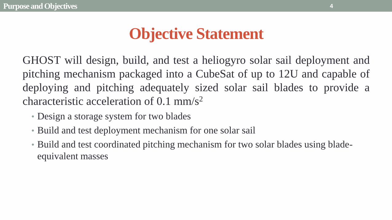
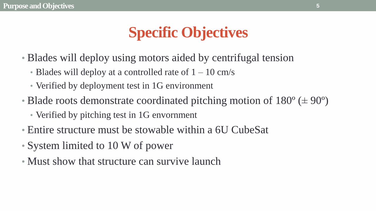
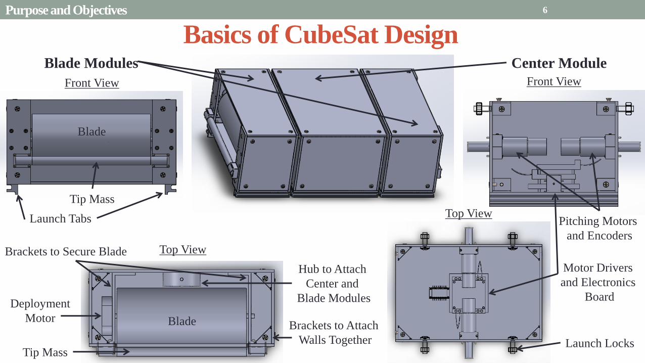
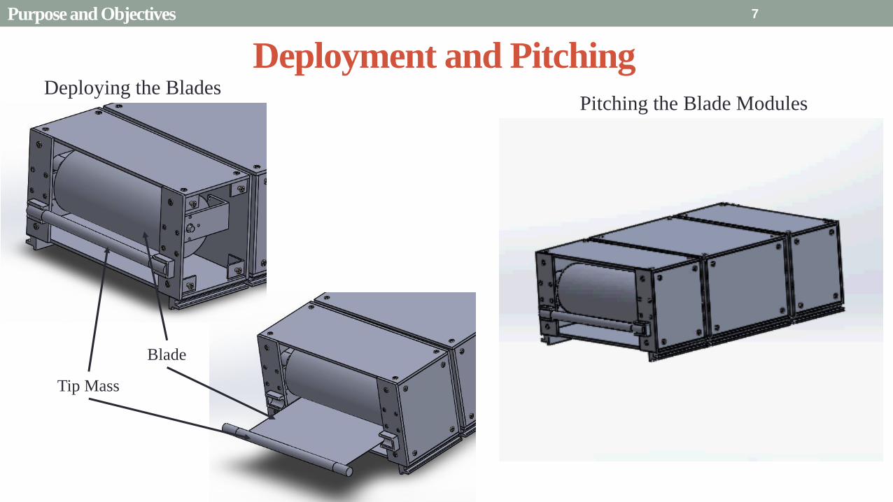
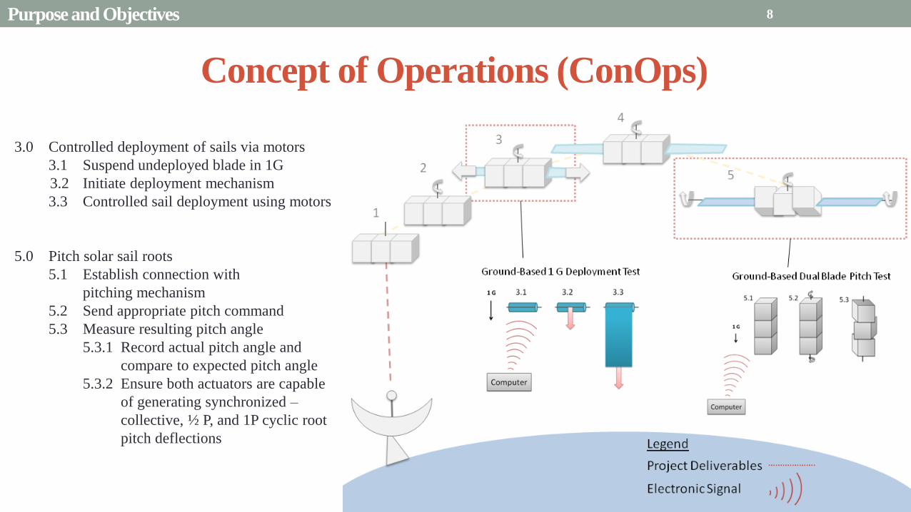
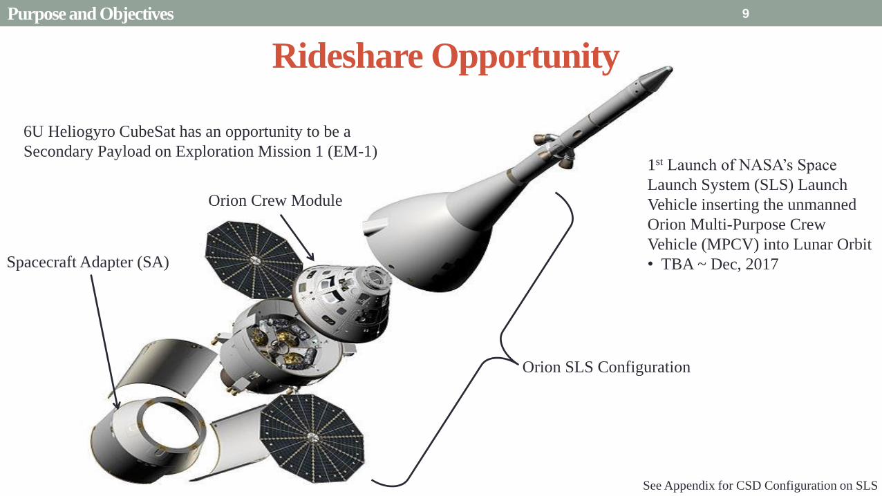
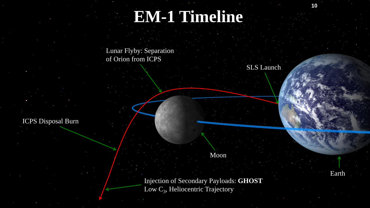
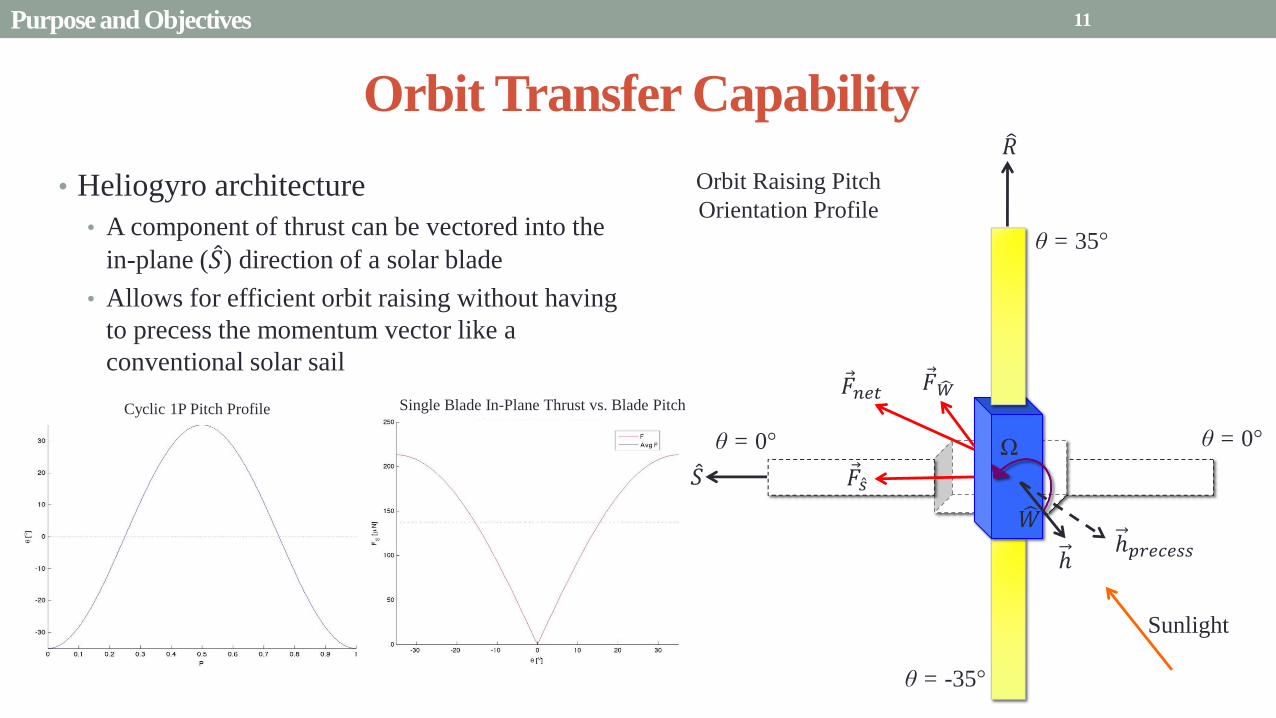
Presentation Sections
bullPurpose and Objectives
bullGHOST Design Solution
bullCritical Project Elements
bullRequirement Satisfaction
bullRemaining Risks
bullVerification and Validation of Design
bullProject Planning
12
Functional Block Diagram 13 GHOST Design Solution
Baseline Design
Blade
Blade
Deployment
(Stepper) Motor
Blade Module
Center Module
Pitching
(Servo) Motor
8 cm
8 cm
13 cm
frac12 cm
frac12 cm
Electronics Board
Stepper Motor Drivers
Servo Motor Drivers
Launch
Tabs
bull Constrained by 6U design
bull 8 cm ndash 13 cm ndash 8 cm with frac12 cm clearance
bull Deployment modules rotate plusmn 90 to pitch
bull Each Blade Module holds rolled sail and Sanyo
Stepper motor
bull Central Pitch Module holds 2 servo-motorsencoders
4 motor drivers and 1 electronics board
bullExtra 2U for power source communication
systems and scientific instruments
bull Launch Tabs for CSD deployment
14 GHOST Design Solution
Baseline Design Central Pitch Module 1 Servomotor stabilized to outer wall
1Pitching Axle fed through hole in wall
2Driven by servo for consistent low-vibration inputs
3Powered by 5V battery
2 PIC receives input and interfaces with drivers
3 18 in flat aluminum walls
1Corner brackets to resist loadsresist vibration
4 Launch locks to reduce vibrational forces during launch
Servo Motors
Pitching Axle
Encoders
Launch Locks
Corner Brackets
Servo Motor Drivers
Stepper Motor Drivers
Electronics Board
with PIC Launch
Tabs
15 GHOST Design Solution
Baseline Design Blade Deployment Modules
bull Hub with set-screws to stabilize
and hold deployment axle
bull Service loop to allow full plusmn90
degree motion
bull S-brackets on sides to stabilize
deployment reel
bull Non-motor side utilizes ball bearing
to assist with low-friction
deployment
bull Axle stabilized by motor and
ball bearing
bull Tip mass of sail held on a C-
bracket on the outer side of the
module
bull Held still by holding torque C-
bracket and stainless steel tape
measure material
Blade
Blade
Hub
Service
Loop
S-brackets Ball Bearing
C-brackets
16 GHOST Design Solution
Micro-
Controller
Stepper
Driver 2 Stepper
Motor 1
Servo
Driver 1
Servo 1
Encoder
DAC
Baseline Design Electronic System
Stepper
Driver 1 Stepper
Motor 2
Servo
Driver 2
Servo 2
Encoder
Hall Sensor Hall Sensor
17 GHOST Design Solution
Initialization CheckState( )
Emergency Stop bull Block DeployPitch
bull Wait for State 2
bull StorePlace( )
Restart bull Check two
previous states
bull Adapt Algorithm( )
Deployment bull CheckDeployed( )
bull Deploy( )
1
2
4
Communications
ISR( )
N-1 = 1
N-1 = 1 N-2 = 3
N-1
= 1
N-2
= 4
N-1 = 1 N-2 = 6
3
6
Pitching bull CheckDeployed( )
bull Pitch( )
SpinUp bull TapeDeploy()
bull Pitch( )
bull EndSpin()
5
Idle bull Idle( )
Emergency Stop
Restart
Deployment
Pitching
SpinUp
LEGEND
Baseline Design Software System
18 GHOST Design Solution
Mass Budget
Attribute Mass
[kg]
Mechanical 218
Electrical 0429
Structural 0265
Total 288
Total Limit 40
Available 112
Mechanical CubeSat plates axles aluminized mylar
stiff steel tip
Electrical Servomotors stepper motors motor drivers
wiring
Structural Brackets braces stabilizers hubs screws
bull If mass goes over-budget triangles can be cut into non-load bearing sections of the CubeSat
bull Reduces mass without compromising structural integrity
bull Slight over-estimation does not account for holes for screwsaxles
19 GHOST Design Solution
Power Budget Individual Components
Power Usage Number per
System
Supply Current
per System (A)
Supply
Voltage (V)
Power Subtotal
(maximum) (W)
Mission Phase
Launch Locks 2 -- 28 15 1
PIC18F87K22 1 001 5 005 1 2 3 4
Sanyo Stepper Motor 2 04 35 14 1 2 3 4
Driver DRV8834 2 1phase 5 5 1 2 3 4
Servomotor
FAULHABER 2036
2 02 5 10 2 4
Servomotor Driver 2 01 5 05 24
Encoder AU-
ZSD1000A
2 004 5
095
2 4
Mission Phase Description Power Budget Total Power Used
Pre-deployment (1) Stepper motor holds Launch Locks initiate unlock gt 10 W 2215 W
Initial Spin-Up (2) Stepper releases 5m stepper holds while pitching 10 W 91 W
Deployment (3) Stepper motor rotates to deploy blade 10 W 715 W
Pitch and Hold (4) Servomotor pitches blade root Stepper motor holds 10 W 91 W
20 GHOST Design Solution
Presentation Sections
bullPurpose and Objectives
bullGHOST Design Solution
bullCritical Project Elements
bullRequirement Satisfaction
bullRemaining Risks
bullVerification and Validation of Design
bullProject Planning
21
21
Critical Project Elements
bull Mechanical
bull Blade Deployment
bull Blade Reel Module can store a sufficiently sized solar sail blade
bull Sized such that will produce a minimum characteristic acceleration of 01 mms^2
bull Motor fits in Blade Reel Module and is capable of a controlled deployment rate of 1 to 10 cms
bull Pitch Actuation
bull Motor can actuate the Blade Reel Module plusmn 90deg
bull Central Module allows for a minimum of 2U (200 cm^3) storage for COMM EPS and scientific payload considerations
bull Structural Integrity
bull Structure can handle shear and tensile stresses present in space and 1G environment
bull Mitigates vibration of external modules on pitch axle and motor
bull Mass amp Volume Budgets
bull Mass and Volume limited by 6 kg and 6U (1 kgU)
22 CPEs
Critical Project Elements
bull Electrical bull MicrocontrollerDriverMotor Connection
bull Functional and wiring sufficiently sized to carry necessary current
bull Inter-module service loop connection
bull Thermal Considerations bull Pitch motor and electronics are sufficiently insulated andor heated by electrical coils
bull Electrical heat dissipation does not overheat internal components
bull Power Budget bull Power usage never exceeds 10 W
bull Software bull Algorithms
bull Integrated with electronics bull Language compatible with microcontroller
bull Capable of producing relevant pitch profiles to be used by pitch motor
bull Control initial deployment deployment rate and confirm deployment status
bull Memory Concerns bull Bus has necessary memory storage on board
23 CPEs
Critical Project Elements
bull Space Concerns
bull Launch Vibrations amp Survivability
bull Structural integrity uncompromised due to launch conditions
bull Launch Locks installed for launch vibration mitigation between external Blade Reel Modules and Internal
Central Module
bull Launch Lock design for support of sail blade tip
bull Canisterized Satellite Dispenser (CSD)
bull CubeSat meets specifications for use in dispenser
bull Initial Spin-Up
bull CubeSat induces rotation of its own accord
bull Use of stainless-steel reinforced sail material at blade tip
24 CPEs
Critical Project Elements
bull Manufacturing and Assembly bull Order of Manufacturing
bull Construction from outside-in
bull Wall Construction bull Thickness sufficient for structural needs and use of fasteners
bull Solar Sail bull Attachment to deployment axle in Blade Reel Module
bull Bonding of stainless-steel supports to sail material
bull Pitching Axle bull Connection between pitch motor and external Blade Reel Module
bull Satisfies tensile and shear stress concerns
bull Minimizes vibration between interfaces
bull Bearings
bull CSD Tabs bull Tabs implemented into construction to allow use in satellite dispenser
25 CPEs
Presentation Sections
bull Purpose and Objectives
bull GHOST Design Solution
bull Critical Project Elements
bull Requirement Satisfaction
bull Controlled Deployment Rate
bull Pitching
bull Survive Launch
bull ElectronicSoftware Integration
bull Manufacturing the CubeSat
bull Summary
bull Remaining Risks
bull Verification and Validation of Design
bull Project Planning
26
Initial Spin-Up
bull Problem Initially deploy solar sail straight without aid in centripetal forces
bull Hardened stainless-steel support attached along middle of last 5 m of Sail Membrane and acts as a ldquotape-measurerdquo
bull Properties of ldquotape measurerdquo bull Dim 5m x 2cm x 127μm
bull ρ = 7860 kgm3
bull m = 998 g
bull A maximum torque of 0147 mNmiddotm required by deployment motor
bull Conditions to reach Ω = 1 RPM
bull 120579119901119894119905119888ℎ = 35deg
bull ∆119905119904119901119894119899 119906119901= 184 days
Solar Blade
Steel Spine
CubeSat
Ω = 1 RPM
Rinitial = 5 m
F = 35 μN
27 Controlled Deployment Rate
Centripetal Acceleration
Deployment
Length
(m)
Centripetal
Acceleration
(ms2)
Sail
Mass
(kg)
Centripetal
Force (N)
5 0055 0014 74times10-5
100 11 0080 0088
200 22 015 033
300 33 022 072
400 44 029 127
500 55 036 197
545 58 038 217
28
Rotation Rate Ω = 1 RPM
Orbital Trajectory
Vtip
Ω
Controlled Deployment Rate
Fg
Fc
Fg is negligible
Space to Earth Comparison
29
CubeSat rotating at 1 RPM rarr centripetal acceleration rarr centrifugal tension
Blade is fully deployed rarr maximum centrifugal tension
Simulate same centrifugal tension the blade would experience in space
Total mass of 36 g used in the deployment test
mTotalSpace = 3775 g
F = 217 N
mTotalEarth = 119865
119892 = 2215 g
The holding torque of the motor used must be able to withstand this force
τ = r times F τ = 0011 Nm
Space Application
Motor
CubeSat
rotating at 1
RPM
Blade Tip mass
F
Top View
Tip mass trajectory
mTM = 2070 g
F = mg
Ground Deployment
r
Mounted to Table Side View
Tip
mass
Motor
Blade
Front View
MotorBus
Interface
Controlled Deployment Rate
Deployment Parts List Electronics Part Voltage (V) Current (A) Interface Dimensions (mm) Cost ($)
Sanyo Stepper Motor 35 03 Input 4 (bipolar) 42times42times11 60
DRV8834 Low-Voltage
Stepper Motor Driver
25-108 05phase Output 4
Input 8 (7 IO 1 CCP)
Power 2 (motor and logic)
Ground 2 (motor and logic)
15times20 10
30 Controlled Deployment Rate
Stepper Motor Stepper Motor Driver
Software Prototype
Deployment
Algorithm
bull Written in MATLAB to prove concept of deployment
bull Need to maintain constant deployment rate
Time Step Passes
Find Rotations Made in Time Step
Calculate Length Deployed
Find new Diameter and
Circumference
Calculate new Rotation Rate
Set Initial Diameter
and Circumference
Calculate Rotation
Rate
31 Controlled Deployment Rate
Presentation Sections
bull Purpose and Objectives
bull GHOST Design Solution
bull Critical Project Elements
bull Requirement Satisfaction
bull Controlled Deployment Rate
bull Pitching
bull Survive Launch
bull ElectronicSoftware Integration
bull Manufacturing the CubeSat
bull Summary
bull Remaining Risks
bull Verification and Validation of Design
bull Project Planning
32
The Need for plusmn 90deg Range of Pitch
Blade
Pitch θ
Condition (Profile Description)
0deg Max Thrust (Collective Blade Surface
Normal to Sunlight)
plusmn 35deg Max Torque (Collective) or Max In-Plane
Thrust (1P Cyclic)
plusmn 90deg No Thrust (Collective Blades Edge on to
Solar Wind)
Full 180deg range of motion for blade pitch necessary for spacecraft to have full capabilities of
controlling the thrust vector See Appendix for further information
33 Pitching
Pitching Parts List Electronics
Part Voltage (V) Current (A) Interface Dimensions (mm) Cost ($)
FAULHABER 2036
BLDC Motor
5 02 Input 3 phase
Sensors 3 HALL
Power 1
36times20 (diameter) 230
Atmel ATA6832-DK
Brushless DC Motor
Controller
5 01 Output 3 phase
Input 1 Serial 2 IO
45times45 208
2 Channel IE2-1024
Encoder
5 04 Output 4 I0
Power 1
165times15 (diameter) 225
34
2036 BLDC Motor
Pitching
Servo Controller
bull Bypass LIN input for direct interface with potentiometer
(Serial input use DAC from microcontroller)
35 Pitching
Pitching Software
Pitch Profile Command Sent
Find corresponding
sinusoid equation for pitching
Command servo to turn to angle in
pitching sinusoid
Compare to Encoder Angle
Given a pitch profile the software will
bull Find the corresponding sinusoid command for the
servos
bull Step through those angles over the time period
bull Compare commanded angle to encoder feedback
bull Adjust for accuracy
Pitching 36
Presentation Sections
bull Purpose and Objectives
bull GHOST Design Solution
bull Critical Project Elements
bull Requirement Satisfaction
bull Controlled Deployment Rate
bull Pitching
bull Survive Launch
bull ElectronicSoftware Integration
bull Manufacturing the CubeSat
bull Summary
bull Remaining Risks
bull Verification and Validation of Design
bull Project Planning
37
Canisterized Satellite Dispenser CSD
bull 6U fits into CSD during launch
bull Gives extra clearance on each side bull Allows for locking mechanism outside the 6U
bull Available with Alum 6061
bull Pushed into orbit on ldquoTabrdquo structure bull Additional tabs added below CubeSat base
bull Able to separate tabs for each separate section
38 Survive Launch
Structural Integrity of Pitching Axle and Selection of
Material
bull Aluminum 6061
bull Lightweight (density of 27gcc)
bull Very strong
bull Inexpensive
bull Pitching Axle ndash rod 1 cm in diameter
bull If made of Aluminum 6061
bull Can withstand shear force of 162 kN (~3600 lbs)
bull Does not take into account ability of motor to withstand torque
F (from Solar
Sail)
τ
39 Survive Launch
Pitching Axle
Launch Locks
bull Sierra Nevada SP-5025 pin puller
bull 350 lbf (1500 N) of shear load
bull Powered by a single timed power pulse to one of
the redundant heater circuits
bull SP -5025 greatly exceeds budget so manual
screw and bolt sized appropriately simulate
launch locks in the prototype
40
SP-5025
SP-5025
Deployed
Stowed
Simulated
Launch Locks
Survive Launch
Credit to SNC
Secure Blade Tip Mass
bull C-brackets attached to exterior walls stabilize tip mass vertically and horizontally
bull Cylindrical tip mass fits securely in brackets on both sides
bull Holding torque of stepper motor and tape-measure material holds tip mass in towards rolled blade
bull Within outer limit required by CSD
41
16 cm
075 cm 2 cm
Survive Launch
Presentation Sections
bull Purpose and Objectives
bull GHOST Design Solution
bull Critical Project Elements
bull Requirement Satisfaction
bull Controlled Deployment Rate
bull Pitching
bull Survive Launch
bull ElectronicsSoftware Integration
bull Manufacturing the CubeSat
bull Summary
bull Remaining Risks
bull Verification and Validation of Design
bull Project Planning
42
Service Loop
Power and input wires needed in for stepper
motor in deployment module
bull 4 12A rated wires AWG 21 D = 073 mm
bull Full loop around pitching axle to allow for
plusmn90deg rotational freedom
bull 1 cm diameter hole through each plate
bull Current must run throughout launch to
keep holding torque
bull Need not worry about freezing later in mission
Wires (red) exit opening in wall loops around
pitching axle enters opening in opposite wall
43 ElectronicsSoftware Integration
Electrical Block Diagram
Micro-
controller
35 V Supply
Stepper
Driver
Stepper
Motor
H4
H5
H3
H6
Key IO
CCP
Power
Serial
GND
Sensor
VDD
M0
M1
ENABLE
CONFIG
GND
DIR
STEP
E0
E2
B2
B1
A1
A2
VMOT GND VDD
5 V Supply
GND
Servo
Driver 1
Servo 1 TX RX
P G A B C
5V GND U V W Servo
Driver 2
Servo 2
P G A B C
5V GND C2 C3 C4 U V W
Encoder
J2 J3 J4 J5 J6 J7
VDC G
C0
(Speed Set)
C0
(Speed Set)
RS 232
DAC
A B C
Encoder VDC G A B C
B5 B4
A3
A7
B7
B6
D4
D3
D4 D3
C2 C3 C4
VoutA
VoutB
SCLK CS
DIN
GND
Tin Rout Vin GND
VDD
A4
SLEEP
FAULT H0
E1
44 ElectronicsSoftware Integration
Microcontroller PIC18F87K22
Board Requirements
bull Serial output for communication with computer
and servomotor controller
bullDAC used for servomotor communication
bull I0 ports for stepper driver interface
bull CCP port for stepper driver interface
bull Header pins for the encoder interface
Total
18 IO
1 CCP
1 TXRX
bull Would need more IO and CCP ports for a second
stepper motor driver
bull Unused ports 37 IO and 10 CCPECCP
ElectronicsSoftware Integration
PCB Design
bull 2 Layer Board
bull FR4 material
bull 1 oz Copper traces
bull Estimated Dimension = 5times5 cm
bull (See Appendix for Electrical Schematic)
EasyPIC PRO
v7 Pinout
80 Pin Development
Board
ElectronicsSoftware Integration
Incompatible Industrial Boards
Presentation Sections
bull Purpose and Objectives
bull GHOST Design Solution
bull Critical Project Elements
bull Requirement Satisfaction
bull Controlled Deployment Rate
bull Pitching
bull Survive Launch
bull ElectronicsSoftware Integration
bull Manufacturing the CubeSat
bull Summary
bull Remaining Risks
bull Verification and Validation of Design
bull Project Planning
47
Manufacturing In-House vs Purchasing
48
Part In-House Purchase Details
CubeSat walls Aluminum will be purchased with correct thickness and
manufactured to needed dimensions
Blade and pitching axle Axles can be cut down to needed length
Corner brackets Brackets can be altered to fit needed dimensions
S-brackets and C-brackets Will have to be machined to fit strict dimensions
Tip mass Tip mass can be cut down to needed length
Tape-measure material Purchased from McMaster-Carr
Solar sail blade material Blade material is provided for free by NASA LaRC
Launch Locks Launch locks we will use are a screw and bolt
Launch Tabs for CSD Tabs must meet strict dimensions to fit into CSD from
Planetary Systems Corporation
Hub to attach pitching axle to blade module Will have to be machined to meet needed dimensions
Screwsnutsbolts All can be purchased in various sizes and lengths
Motorsencoders and motor drivers All purchased to meet necessary requirements
Electronics board Will have to be made to accommodate needed electronics
Stabilizers to hold pitching motors Will have to be machined to properly fit around motors
Manufacturing the CubeSat
Assembly Procedure
49 Manufacturing the CubeSat
Bonding Mylar to Spool and Stiff Material
bull Loctite Super Glue Professional
bull Shear strength of 01 Nmm2
bull Cross-Sectional Area = 6575 mm2
bull Shear Stress = 33e-4 Nmm2
bull Blade will retain 4 rolls around axle at
final length
bull Loctite to bond stainless steel stiff
material to Mylar and to spool
F = mg = 217 N
Motor
Blade frac14 of roll glued
50 Manufacturing the CubeSat
Fixing Deployment Motor to S-Bracket
51
bull Deployment stepper motor is attached to S-bracket
bull S-bracket stabilized to back of blade deployment
module and vertical CubeSat walls
bull Motor is capable of being screwed directly to S-bracket
bull S-bracket has thickness of 18 inch
Holes for screws to
stabilize S-bracket
Hole for motor shaft
or press-fit ball
bearing to attach to
blade axle
Holes to screw motor
to S-bracket
Manufacturing the CubeSat
Pitching Axle Interfaces
bull Pitching axle to motor axle
bull Motor axle (smaller) fits into pitching
axle (larger) using set-screws
bull Pitching Axle to Blade Reel
Module
bull Axle fixed by set screws inside a hub
52
Pitching Axle
Hub
Motor Axle
4 Set Screws
Manufacturing the CubeSat
Presentation Sections
bull Purpose and Objectives
bull GHOST design solution
bull Critical Project Elements
bull Requirement Satisfaction
bull Controlled Deployment Rate
bull Pitching
bull Survive Launch
bull ElectronicSoftware Integration
bull Manufacturing the CubeSat
bull Summary
bull Remaining Risks and Mitigations
bull Verification and Validation of Design
bull Schedule and remaining work
53
Requirements Satisfaction
Aspect Requirement GHOST Specification
Mass 1 kgU 288 kg
Volume lt= 12U 6U
Life Span 4 months Greater than 4 months
Space Applicable
While design does not need to be
space worthy it should be applicable
to being used in space
All components are picked for
realistic use in space with minimal
cost parts and increased life span
54 Summary
Requirements Satisfaction
Aspect Requirement GHOST Specification
Characteristic Acceleration ac ge 01 mms2 ac = 03868 mms2
Sail Aspect Ratio AR ge 1001 AR = 38931
Sail Deployment Speed 1 cms le 10cms ~5 cms
Pitching Range Ability to pitch blades plusmn 90deg Ability to pitch blades plusmn 90deg
Pitching Coordination Multiple blade coordination when
pitching
Can pitch both blades at once either to
same angle or opposite angles
55 Summary
Presentation Sections
bullPurpose and Objectives
bullGHOST Design Solution
bullCritical Project Elements
bullRequirement Satisfaction
bullRemaining Risks
bullVerification and Validation of Design
bullProject Planning
56
Design Risks
Severity
Likelihood Marginal Major
Often Pitch angle error root not
following tip
Occasional Power loss COMM loss
Structural survivability
pitching motor failure
Improbable Small tear in Mylar Deploy too fast stowage
and deployment of Mylar
Axle failure
launch fail
space dust
deployment motor failure
57 Remaining Risks
Logistical Risks
Severity
Likelihood Minor Marginal Major
Often Parts delayed due to US
Postal Service
Occasional Structural consultation
unavailable
Ball vibrations test is not
available machine parts
not done on schedule
Government shutdown and
we canrsquot get Mylar or help
from NASA
Improbable No time for pitching test
High Bay in Fleming is
unavailable motors donrsquot
show up
58 Remaining Risks
Financial Risks
Severity
Likelihood Minor Marginal Major
Often Repurchase parts
Occasional Motor breaks Price of shake table
Improbable Hyper inflation
59 Remaining Risks
Presentation Sections
bullPurpose and Objectives
bullGHOST Design Solution
bullCritical Project Elements
bullRequirement Satisfaction
bullRemaining Risks
bullVerification and Validation of Design
bullProject Planning
60
Deployment System
Validate that the blade is deployed at a constant rate of 1-10 cms in a high bay
room
Verify that the motor can deploy at constant rate
Verify with test that the deployment system does not use more than the maximum power available of 10W
Validate that the blade can successfully deploy a blade with tape measure
material at a constant rate along ground
Verify with demonstration that the tape measure material can extend length of
blade
Verification and Validation
Verification and Validation
61
Blade Deployment Testing Information
bull Location Prof Frewrsquos High Bay Lab
bull Scheduled MarchApril with late night access to avoid
scheduling conflicts
bull Measurement Tape measure for distance and video
camera for time
bull Power Delivered 6253A Dual DC Power Supply
delivers 0-20 V and 0-3A
Tape measure
marking
distance up
wall
Kinematic Model
bull Torque from motor drives a constant velocity deployment
120591119898119900119905119900119903 = 120591119903119900119897119897 + 120591119901119906119904ℎ119894119899119892 119879119872 minus 120591119892119903119886119907119894119905119910 119879119872
120591119903119900119897119897 =119889119868119903119900119897119897
119889119905120596119903119900119897119897 + 119868119903119900119897119897
119889120596119903119900119897119897
119889119905
120591119901119906119904ℎ119894119899119892 119879119872 =119889119898119890119909119905
119889119905119903119903119900119897119897119907 + 119898119890119909119905
119889119903119903119900119897119897
119889119905119907
120591119892119903119886119907119894119905119910 119879119872 = 119898119890119909119905119903119903119900119897119897119892 bull 120649119945119952119949119941119946119951119944 = 120782 120782120790120787 N∙m 120649119950119952119941119942119949119950119938119961 = 120782 120782120782120789 N∙m
Power Supply
Verification and Validation
CubeSat Wire
62
Pitching System
Validate that the blade reel modules experience coordinated pitching
Verify that one blade reel module experiences periodic
motion
Verify that the blade reel module rotates to 0deg upon
initialization
Verify that the blade pitches to a given command
angle
Verify that the motorencoder system does not exceed power
available
Verification and Validation
Verification and Validation
63
Verify Pitching Angle Experiment Equipment and Specs
bull Use R60D RVIT (Rotary Variable Inductance Transducer) sensor to measure angles attaches to pin (red) in line with pitching axis bull Measures ranges of plusmn60deg rotation
bull Input Voltage = plusmn15 V
bull Output Voltage = plusmn75 V
bull Resolution = 0125 Vdeg
bull 119891119898119886119909 = 20 Hz
bull Use AD524 Precision Amplifier Instrumentation for signal conditioning bull Input Voltage plusmn10 V
bull Output Voltage plusmn10V
bull Requires Supply Voltage plusmn15
bull Use NI 9201 bull Input Voltage plusmn10 V
bull Has a USB output that can connect to a computer where vi program records
Experiment Set-Up
R60D RVIT
AD524
NI 9201 PC via USB
Verification and Validation 64
Verify Periodic Motion Experiment
bull Using the R60D RVIT set-up to measure deflection angles
bull With data of the angle deflection 120579 angular velocity 120596 and angular acceleration 120572 can be measured bull Motor restriction 120591119898119886119909 = 032 Nmiddotm
bull Model restriction 120596119898119886119909 = Ω2 if Ω = 2rpm 120596119898119886119909 = 02094 rads
Validation Model
bull R60D RVIT measures plusmn60deg deflection angles bull Critical condition blade reel module pitches plusmn90deg Ω=2rpm
bull 120572119888 = 00172 rads2 and 120596119898 = 0164 rads thus 120591119898 = 0083 mNmiddotm (119868119898119900119889 = 00048 kgmiddotm2)
120579 119905 120596 119905 120572 119905
Verification and Validation 65
Verification and Validation
Structural System
Validate that the final design can survive launch by using a shake
table
Verify the structural integrity by demonstrating that all stationary parts are
static
Verification and Validation 66
Trade Study FEM vs Vibration Table
Cost Time Experience
Similar to
Actual
Launch
Guaranteed Can
Do Total
FEM 4 1 1 3 4 215
Vibration
Table 2 3 4 4 2 32
Weight () 5 30 25 20 20 100
67 Verification and Validation
See Appendix for Full Trade Study
Validate Structural Stability
bull Will use a shaker table from Ball Aerospace
bull Cost = $250hr
bull Schedule Time to be determined in April
bull Specifications Peak vibration occurs with 34g at
frequency of 16 Hz (Saturn V)
bull Will be verified by examining the structural integrity
of the manufacturing
Verification and Validation 68
CubeSat
Shake Table
Presentation Sections
bullPurpose and Objectives
bullGHOST Design Solution
bullCritical Project Elements
bullRequirement Satisfaction
bullRemaining Risks
bullVerification and Validation of Design
bullProject Planning
69
Organizational Chart
Mark
Dolezal
Emily
Proano
Lauren
Persons
Casey
Myers
Nicholas
Busbey
Taylor
Smith
Karynna
Tuan
Megan
Scheele
Project
Manager
Software
Lead
Electrical
Lead
Systems Test and
Safety
Manufacturing
Lead Mechanics
Lead
CFO and
Materials
Lead
Organizing
team
meetings
Supporting
other leads
Non CPE
Tasks
Deployment
Control
Pitching
Control Motors and
Electronics
Power
Integrate
all system Perform
and Plan
tests
Manufacture
all in-house
parts
SolidWorks
Keep track
of financial
spending
Right
materials
are being
utilized
CubeSat
Assembly
Specific
System
Requirements
70 Project Planning
GHOST
Materials Mechanical Electrical Software Documents
Shake Table
Vibration
Analysis
Mechanical
Layout
Power Budget Pitch Control
Algorithm
Deployment
Rate Control
Algorithm SolidWorks
Model
Electrical
Wiring Layout
Thermodynamic
Analysis of
Electronic System
Mass Budget
Prototype of
CubeSat Bus
Motor
Subsystem
CDR
FFR
Spring
Schedule
Financial
Budget
Work Breakdown Structure (WBS)
Mylar from
NASA
Spin Up
Algorithm
Emergency
StopRestart System
71 Project Planning
PCB Design
Spring
Documents
113 120 127 203 210 217 224 303 310 317 324 331 407 414 421 428
MSR TRR SFR PFR
Time (date)
Purchase
motorsdrivers
Preliminary code
Electronic
integration
Test code
Electronicscode
interface
Purchase
raw materials
Manufacture frame
Assemble bus
Manufacture
remaining parts
Integrate system
Deployment test
Pitching test
Vibration test
Ta
sks
72
GHOST Spring Schedule
Project Planning
Planned Uncertainty
Key
Test Plan Test Scheduled Facility Specialized Equipment
Verify Pitch Angle 317 ITLL R60D RVIT NI 9201 AD524 Oscilloscope bench
power source
Zero Pitch Angle 317 ITLL R60D RVIT NI 9201 AD524 Oscilloscope bench
power source
Measure power used in
pitchdeployment 317 ITLL Ammeter voltmeter bench power source
Verify constant deployment 324 ITLL Firewire camera bench power source
ASEN2003BallTrackervi
Verify periodic motion 324 ITLL R60D RVIT NI 9201 AD524 Oscilloscope bench
power source
Validate tape measure ground
deployment 331 ITLL
Bench power source tape measure stop watch rollers
for tip mass
Validate coordinated pitching 331 ITLL R60D RVIT NI 9201 AD524 oscilloscope bench
power source
Validate 1g blade deployment 331-414 Prof Frew
high bay
Portable 6253A Dual DC Power Supply ladder tape
measure video camera
Validate launch ready 414 Ball Aero Shake Table
Project Planning 73
Cost Table ndash Structural Components
Part Price per
part NeededVolume Needed Total Price Supplier
Aluminum 6061 Sheet
(18rdquo thick) $ 8976 2ft times 2ft times 18 in $ 8976 The Metals Depot
Aluminum 6061 rod
(14 in diameter) $280 2 ft $280 The Metals Depot
Aluminum6061 rod
(716 in diameter) $494 2 ft $494 The Metals Depot
Steel Corner Brackets
(34rdquo times 12rdquo)
$197 4
braces 16 $788 Home Depot
Hardened 302 Stainless
Steel $3300 2 cm times 5 m times 127 microm $3300 McMaster-Carr
Total $11834
74 Project Planning
Cost Table ndash Electrical Components
Part Price per
part Needed Total Price Supplier
Sanyo Stepper Motor $ 5995 2 $11990 Pololu Electronics and Robotics
DRV8834 Low-Voltage Stepper
Motor Driver $995 2 $1990 Pololu Electronics and Robotics
FAULHABER 2036 BLDC
Servo Motor $23000 2 $46000 MicroMo Micro Motion Solutions
Atmel ATA6832-DK Brushless
DC Motor Controller $20800 2 $41600 Atmel
Encoder AU-ZSD1000A $22500 2 $45000 MicroMo Micro Motion Solutions
PIC18F87K22 Microcontroller $500 1 $500 Microchip
AD-524 Signal Converter $1767 1 $1767 Agilent
Total $148847
75 Project Planning
Questions
76
References
bull wwwloctiteproductscom
bull Vallado D A Fundamentals of Astrodynamics and Applications
bull Guerrant D Lawrence D Heaton A Earth Escape Capabilities of the Heliogyro Sail AIAA Paper
bull wwwspaceflightnowcom
bull Guerrant D HGVizGuim MATLAB Program
bull httpwwwmicromocombrushless-dc-motorsaspx
bull httpwwwfaulhabercomservletcomitmrwawservletAnzeigefremdaufruf=jaampkdid=40929ampsprachid=1amphtdigurl=n169933i95222html
bull httpwwwpololucom
bull httpasmmatwebcomsearchSpecificMaterialaspbassnum=MA6061t6
bull httpwwwruagcomthermalSpace_Thermal_HardwareMulti_Layer_Insulation
bull Helgesen Bryan Sierra Nevada Corporation
77
GyroSail Launch Configuration and Deployment Sequence
78
1 Launch configuration (6U) 2 Blade reel modules pitch to zero Fits within a 6U or 12U dispenser
3 PV arrays deploy
Other array configurations are possible
williamkwilkienasagov NASA PREDECISIONAL - FOR DISCUSSION PURPOSES ONLY
78 Appendix
GyroSail Primary Bus Systems Based on modified JPLU MichUCLACal PolyUT INSPIRE bus
williamkwilkienasagov
05U cold gas thruster ACS for detumbling
and initial spin-up
(httpwwwaustinsatnet)
05U EPS battery CampDH UHF backup
comms (U Mich) 05U DSN-compatible X-band
communications (JPL)
05U COTS star trackerimager ADC (BCT) sail
module processor (CU)
Klesh A et al 2013 ldquoINSPIRE Interplanetary NanoSpacecraft Pathfinder In Relevant Environmentrdquo Proceedings of the AIAAUSU Conference on Small Satellites Around the Corner SSC13-
XI-8 httpdigitalcommonsusuedusmallsat2013all2013127
NASA PREDECISIONAL - FOR DISCUSSION PURPOSES ONLY
79 Appendix
COMM Subsystem
bull 18 m Ka-band antennas at White
Sands New Mexico
bull Goddard Space Flight Center
Greebelt Maryland USA
supplied the Mulemba Space
Center in Angola
80 Appendix
Orion Crew
Module
6U Canisterized Satellite
Dispenser (CSD) ESPA Ring
Spacecraft
Adapter
Interim Cryogenic Propulsion
Stage (ICPS)
Secondary Payload Attachment to SLS
The SLS design is currently going through CDR An ESPA
ring is not currently in place but is mentioned in the SLS
CONOPS in order to accommodate secondary payloads
81 Appendix
Max Thrust Condition Collective 90deg pitch profile
Max thrust normal to orbital plane
(Halo orbits orbital plane rotation ie
inclination change)
82
Credit to Dan Guerrant
Appendix
Max Thrust Condition
F vs β M vs β
83
Credit to Dan Guerrant
Appendix
No Thrust Condition Collective 0deg pitch profile
Zero thrust
84
Credit to Dan Guerrant
Appendix
No Thrust Condition
F vs β M vs β
85
Credit to Dan Guerrant
Appendix
Max Torque Condition Collective 35deg pitch profile
Max torque used for spinning up sc
(opposite orientation for despinning)
86
Credit to Dan Guerrant
Appendix
Max Torque Condition
F vs β M vs β
87
Credit to Dan Guerrant
Appendix
Max In-Plane Thrust Condition Cyclic 35deg pitch profile
Max thrust in in-plane (d2) direction for orbit raising
88
Credit to Dan Guerrant
Appendix
Max In-Plane Thrust Condition
F vs β M vs β
89
Credit to Dan Guerrant
Appendix
Orbit Raising
F
90 Appendix
Thermal Space Concerns
bull Material Concerns
bull Aluminum 6061 -196 degC to 160deg C
bull Electronics Concerns
bull Typical Operating Temperature -55 to 80 degC
bull Countermeasures
bull Multi-layer Insulation AAErotherm S10-190
bull (0005 ndash 0035 Wm2K)
bull Battery operated heaters for pre-sail deployment
Multi-layer Insulation
Layer 1 1 x Outer layer
Layer 2 8 x 03 mil VDAPolyimideVDA perf
8 x Woven Polyester netting
Layer 3 1 x Outer layer
Layer 4 1 x Woven Polyester netting
91 Appendix
Rolled Up Blade Reel Calculation Optimal Sail Length 545 m ndash Sail chord of 14 cm
Max Diameter of Spool 598 cm
Diameter of Axle 05 cm
Length of Stiff Material 5 m
Dimension of Stiff Material 5 m times 2 cm times 127 microm
92 Appendix
Torque calculation
bull Note current calculated via T=kI (where T is torque I is amp k is the torque
constant specific to the motor)
T = kI
(k = 005 NmA)
93 Appendix
Servo Controller
94 Appendix
Encoder Dimensions and Interface
bull FAULHABER IE2-1024
95 Appendix
Stepper Motor Torque
96 Appendix
Motor Phases (Stepper)
97 Appendix
98 Appendix
99 Appendix
100 Appendix
101 Appendix
Microcontroller
102 Appendix
ATA6832 Phase Output Chip
103 Appendix
ATA6624 Bypassed Chip
bull Bypassed chip
on servo controller
104 Appendix
Power Budget
105 Appendix
Wire Gauge
bull Stepper Motor 26AWG (04 mm diameter)
bull Servomotor 24 AWG (051 mm diameter)
bull Encoder 24 AWG
Voltage Drop () AWG Max Gauge
001 5
01 15
1 25
5 32
NOTE Voltage drop calculated at 1A and 40 cm of wire
106
24 AWG Wire
Appendix
Trade Study ndash FEM vs Vibration Table
Factor 4 3 2 1
Cost No money 0 gt C gt $100 $100 gt C gt $300 $300 lt C
Time 0 min lt T lt 30 min 30 min lt T lt 2 hrs 2 hrs lt T lt 1 day 1day lt T
Experience Everyone has
experience
A couple people
know how to
1 person has
experience
No one has
experience
Similar To Actual
Launch Simulate real launch
Doesnrsquot have all
variables experienced
Has only a couple
similarities
No similarities to
launch
Guaranteed Can Do
Donrsquot need any
outside equipment or
help
Need outside
equipment but
guaranteed use
Need outside
equipment but own
work at higher
priority
Need outside
equipment but canrsquot
use
Scoring
107 Appendix
Weighting
Weight () Category Reasoning
5 Cost Have a lot of extra $ in the budget
30 Time Have a strict schedule but not a main focus of the
project
25 Experience If no one has experience it will take a lot of time
20 Similar to Actual Launch Needs to be like actual launch
20 Guaranteed Can Do Needs to be able to accomplish but not the most
important focus
108 Appendix
Finite Element Method (FEM)
Objectives Description ProCon
Cost No money because one of us
would do it Pro
Time A lot of time to learn and then
perform FEM Con
Experience No one in group has FEM
experience Con
Similar to Actual Launch Very similar to actual launch Pro
Guaranteed Can Do All we need is paper pen and
theory to do Pro
109 Appendix
Vibration Table
Objective Description ProCons
Cost $250hr Con
Time A hour on the table should simulate
launch Pro
Experience Donrsquot need experience to run
vibration table Pro
Similar to Actual Launch Actually putting our system through
vibration stress Pro
Guaranteed Can Do No guarantee but most likely can Con
110 Appendix
SpinUp State
1 Check value of SpinUp to see if satellite is already spun up
bull Continue if satellite is not already spun-up
2 Deploy the tape stiffened length of the blade
3 Pitch to the spin up angle
4 Wait until characteristic angular velocity is reached
5 Pitch to pre-deployment position
6 Save SpinUp as completed
Appendix 111
Deployment State
1 Check if satellite has been spun up yet
bull Continue if it has
2 Check if blades are already deployed
bull Continue if they havenrsquot
3 Run deploy algorithm until blades are fully deployed
4 Save value saying blades have been deployed
Appendix 112
Pitching State
1 Check if satellite has been spun up
bull Continue if satellite has been spun up
2 Check if blades have been deployed
bull Continue if blades have been deployed
3 Look at commanded pitch profile
4 Find correlated sinusoid command
5 Command servo to pitch angle for the time in the orbit
6 Continue until given a new pitch command
Appendix 113
Emergency Stop
1 Save which state was interrupted
2 Save last position in interrupted
state
3 Wait until Restart command is
received
1 Check two previous states to see
what is being restarted
2 Look at saved last position in
state being restarted
3 Adapt the algorithm of the state
to continue where left off
Restart
Appendix 114
Comparison with Previous Heliogyro Concepts MIT (1989) NASA (2011) GHOST
Total sail craft mass (kg) 18 84
288 (6)
Characteristic acceleration ac
(mms2) 06 10 03868 (01854)
Sail reflective area (m2) 1200 960 1526
Non-sail mass (kg) 5 5 --
Number of sail blades 8 6 2
Blade chord (m) 15 08 014
Blade length (m) 100 200 545
Rotational period (minutes) 3 3 1
Blade root stress (Pa) 8650 34000 --
Blade root allowable stress (Pa) 55 M 55 M --
Blade root tension load (N) 01 007 --
115 Appendix
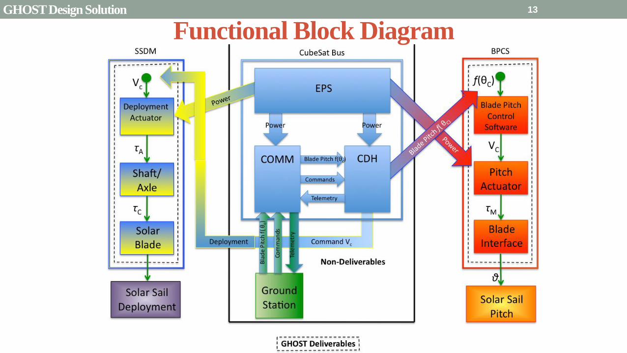
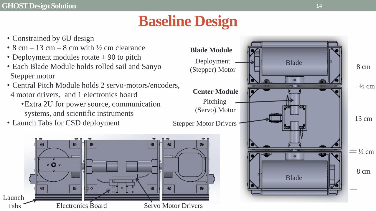
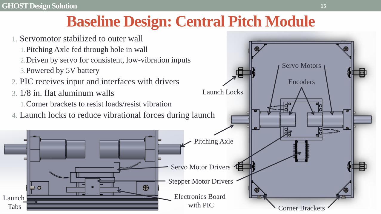
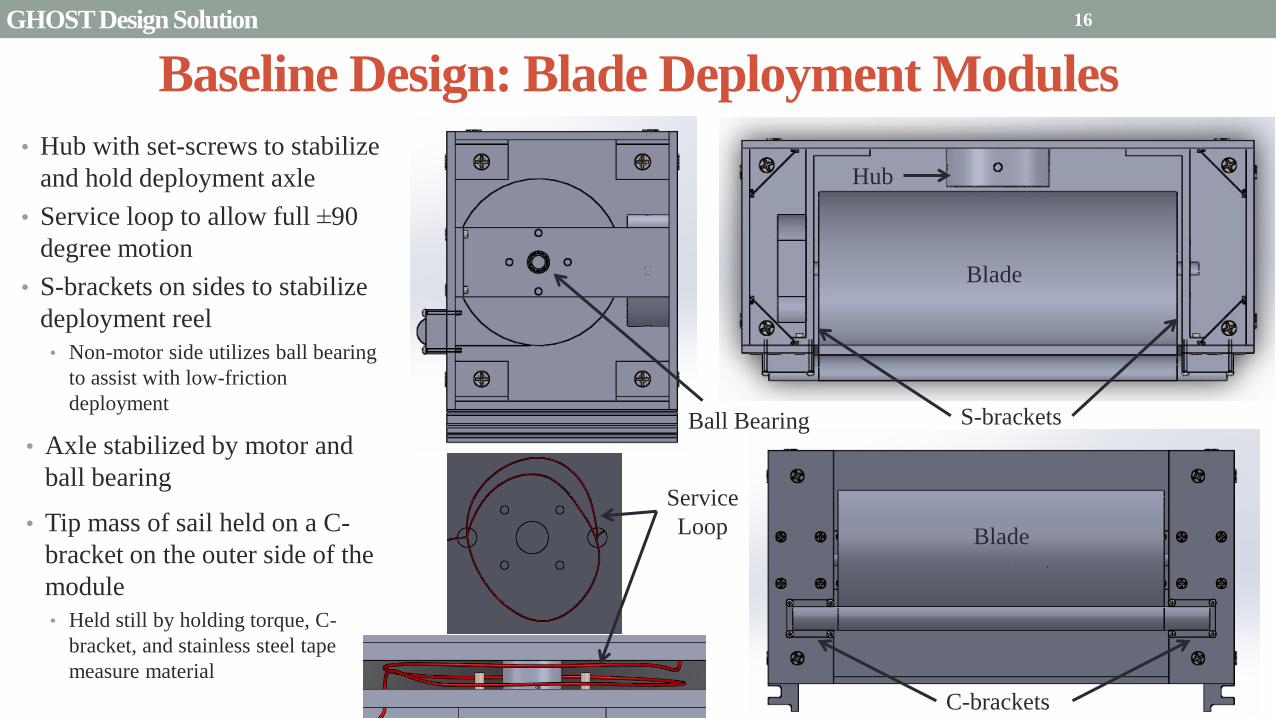
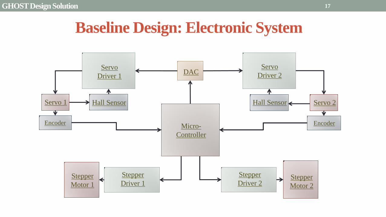
Micro-
Controller
Stepper
Driver 2 Stepper
Motor 1
Servo
Driver 1
Servo 1
Encoder
DAC
Baseline Design Electronic System
Stepper
Driver 1 Stepper
Motor 2
Servo
Driver 2
Servo 2
Encoder
Hall Sensor Hall Sensor
17 GHOST Design Solution
Initialization CheckState( )
Emergency Stop bull Block DeployPitch
bull Wait for State 2
bull StorePlace( )
Restart bull Check two
previous states
bull Adapt Algorithm( )
Deployment bull CheckDeployed( )
bull Deploy( )
1
2
4
Communications
ISR( )
N-1 = 1
N-1 = 1 N-2 = 3
N-1
= 1
N-2
= 4
N-1 = 1 N-2 = 6
3
6
Pitching bull CheckDeployed( )
bull Pitch( )
SpinUp bull TapeDeploy()
bull Pitch( )
bull EndSpin()
5
Idle bull Idle( )
Emergency Stop
Restart
Deployment
Pitching
SpinUp
LEGEND
Baseline Design Software System
18 GHOST Design Solution
Mass Budget
Attribute Mass
[kg]
Mechanical 218
Electrical 0429
Structural 0265
Total 288
Total Limit 40
Available 112
Mechanical CubeSat plates axles aluminized mylar
stiff steel tip
Electrical Servomotors stepper motors motor drivers
wiring
Structural Brackets braces stabilizers hubs screws
bull If mass goes over-budget triangles can be cut into non-load bearing sections of the CubeSat
bull Reduces mass without compromising structural integrity
bull Slight over-estimation does not account for holes for screwsaxles
19 GHOST Design Solution
Power Budget Individual Components
Power Usage Number per
System
Supply Current
per System (A)
Supply
Voltage (V)
Power Subtotal
(maximum) (W)
Mission Phase
Launch Locks 2 -- 28 15 1
PIC18F87K22 1 001 5 005 1 2 3 4
Sanyo Stepper Motor 2 04 35 14 1 2 3 4
Driver DRV8834 2 1phase 5 5 1 2 3 4
Servomotor
FAULHABER 2036
2 02 5 10 2 4
Servomotor Driver 2 01 5 05 24
Encoder AU-
ZSD1000A
2 004 5
095
2 4
Mission Phase Description Power Budget Total Power Used
Pre-deployment (1) Stepper motor holds Launch Locks initiate unlock gt 10 W 2215 W
Initial Spin-Up (2) Stepper releases 5m stepper holds while pitching 10 W 91 W
Deployment (3) Stepper motor rotates to deploy blade 10 W 715 W
Pitch and Hold (4) Servomotor pitches blade root Stepper motor holds 10 W 91 W
20 GHOST Design Solution
Presentation Sections
bullPurpose and Objectives
bullGHOST Design Solution
bullCritical Project Elements
bullRequirement Satisfaction
bullRemaining Risks
bullVerification and Validation of Design
bullProject Planning
21
21
Critical Project Elements
bull Mechanical
bull Blade Deployment
bull Blade Reel Module can store a sufficiently sized solar sail blade
bull Sized such that will produce a minimum characteristic acceleration of 01 mms^2
bull Motor fits in Blade Reel Module and is capable of a controlled deployment rate of 1 to 10 cms
bull Pitch Actuation
bull Motor can actuate the Blade Reel Module plusmn 90deg
bull Central Module allows for a minimum of 2U (200 cm^3) storage for COMM EPS and scientific payload considerations
bull Structural Integrity
bull Structure can handle shear and tensile stresses present in space and 1G environment
bull Mitigates vibration of external modules on pitch axle and motor
bull Mass amp Volume Budgets
bull Mass and Volume limited by 6 kg and 6U (1 kgU)
22 CPEs
Critical Project Elements
bull Electrical bull MicrocontrollerDriverMotor Connection
bull Functional and wiring sufficiently sized to carry necessary current
bull Inter-module service loop connection
bull Thermal Considerations bull Pitch motor and electronics are sufficiently insulated andor heated by electrical coils
bull Electrical heat dissipation does not overheat internal components
bull Power Budget bull Power usage never exceeds 10 W
bull Software bull Algorithms
bull Integrated with electronics bull Language compatible with microcontroller
bull Capable of producing relevant pitch profiles to be used by pitch motor
bull Control initial deployment deployment rate and confirm deployment status
bull Memory Concerns bull Bus has necessary memory storage on board
23 CPEs
Critical Project Elements
bull Space Concerns
bull Launch Vibrations amp Survivability
bull Structural integrity uncompromised due to launch conditions
bull Launch Locks installed for launch vibration mitigation between external Blade Reel Modules and Internal
Central Module
bull Launch Lock design for support of sail blade tip
bull Canisterized Satellite Dispenser (CSD)
bull CubeSat meets specifications for use in dispenser
bull Initial Spin-Up
bull CubeSat induces rotation of its own accord
bull Use of stainless-steel reinforced sail material at blade tip
24 CPEs
Critical Project Elements
bull Manufacturing and Assembly bull Order of Manufacturing
bull Construction from outside-in
bull Wall Construction bull Thickness sufficient for structural needs and use of fasteners
bull Solar Sail bull Attachment to deployment axle in Blade Reel Module
bull Bonding of stainless-steel supports to sail material
bull Pitching Axle bull Connection between pitch motor and external Blade Reel Module
bull Satisfies tensile and shear stress concerns
bull Minimizes vibration between interfaces
bull Bearings
bull CSD Tabs bull Tabs implemented into construction to allow use in satellite dispenser
25 CPEs
Presentation Sections
bull Purpose and Objectives
bull GHOST Design Solution
bull Critical Project Elements
bull Requirement Satisfaction
bull Controlled Deployment Rate
bull Pitching
bull Survive Launch
bull ElectronicSoftware Integration
bull Manufacturing the CubeSat
bull Summary
bull Remaining Risks
bull Verification and Validation of Design
bull Project Planning
26
Initial Spin-Up
bull Problem Initially deploy solar sail straight without aid in centripetal forces
bull Hardened stainless-steel support attached along middle of last 5 m of Sail Membrane and acts as a ldquotape-measurerdquo
bull Properties of ldquotape measurerdquo bull Dim 5m x 2cm x 127μm
bull ρ = 7860 kgm3
bull m = 998 g
bull A maximum torque of 0147 mNmiddotm required by deployment motor
bull Conditions to reach Ω = 1 RPM
bull 120579119901119894119905119888ℎ = 35deg
bull ∆119905119904119901119894119899 119906119901= 184 days
Solar Blade
Steel Spine
CubeSat
Ω = 1 RPM
Rinitial = 5 m
F = 35 μN
27 Controlled Deployment Rate
Centripetal Acceleration
Deployment
Length
(m)
Centripetal
Acceleration
(ms2)
Sail
Mass
(kg)
Centripetal
Force (N)
5 0055 0014 74times10-5
100 11 0080 0088
200 22 015 033
300 33 022 072
400 44 029 127
500 55 036 197
545 58 038 217
28
Rotation Rate Ω = 1 RPM
Orbital Trajectory
Vtip
Ω
Controlled Deployment Rate
Fg
Fc
Fg is negligible
Space to Earth Comparison
29
CubeSat rotating at 1 RPM rarr centripetal acceleration rarr centrifugal tension
Blade is fully deployed rarr maximum centrifugal tension
Simulate same centrifugal tension the blade would experience in space
Total mass of 36 g used in the deployment test
mTotalSpace = 3775 g
F = 217 N
mTotalEarth = 119865
119892 = 2215 g
The holding torque of the motor used must be able to withstand this force
τ = r times F τ = 0011 Nm
Space Application
Motor
CubeSat
rotating at 1
RPM
Blade Tip mass
F
Top View
Tip mass trajectory
mTM = 2070 g
F = mg
Ground Deployment
r
Mounted to Table Side View
Tip
mass
Motor
Blade
Front View
MotorBus
Interface
Controlled Deployment Rate
Deployment Parts List Electronics Part Voltage (V) Current (A) Interface Dimensions (mm) Cost ($)
Sanyo Stepper Motor 35 03 Input 4 (bipolar) 42times42times11 60
DRV8834 Low-Voltage
Stepper Motor Driver
25-108 05phase Output 4
Input 8 (7 IO 1 CCP)
Power 2 (motor and logic)
Ground 2 (motor and logic)
15times20 10
30 Controlled Deployment Rate
Stepper Motor Stepper Motor Driver
Software Prototype
Deployment
Algorithm
bull Written in MATLAB to prove concept of deployment
bull Need to maintain constant deployment rate
Time Step Passes
Find Rotations Made in Time Step
Calculate Length Deployed
Find new Diameter and
Circumference
Calculate new Rotation Rate
Set Initial Diameter
and Circumference
Calculate Rotation
Rate
31 Controlled Deployment Rate
Presentation Sections
bull Purpose and Objectives
bull GHOST Design Solution
bull Critical Project Elements
bull Requirement Satisfaction
bull Controlled Deployment Rate
bull Pitching
bull Survive Launch
bull ElectronicSoftware Integration
bull Manufacturing the CubeSat
bull Summary
bull Remaining Risks
bull Verification and Validation of Design
bull Project Planning
32
The Need for plusmn 90deg Range of Pitch
Blade
Pitch θ
Condition (Profile Description)
0deg Max Thrust (Collective Blade Surface
Normal to Sunlight)
plusmn 35deg Max Torque (Collective) or Max In-Plane
Thrust (1P Cyclic)
plusmn 90deg No Thrust (Collective Blades Edge on to
Solar Wind)
Full 180deg range of motion for blade pitch necessary for spacecraft to have full capabilities of
controlling the thrust vector See Appendix for further information
33 Pitching
Pitching Parts List Electronics
Part Voltage (V) Current (A) Interface Dimensions (mm) Cost ($)
FAULHABER 2036
BLDC Motor
5 02 Input 3 phase
Sensors 3 HALL
Power 1
36times20 (diameter) 230
Atmel ATA6832-DK
Brushless DC Motor
Controller
5 01 Output 3 phase
Input 1 Serial 2 IO
45times45 208
2 Channel IE2-1024
Encoder
5 04 Output 4 I0
Power 1
165times15 (diameter) 225
34
2036 BLDC Motor
Pitching
Servo Controller
bull Bypass LIN input for direct interface with potentiometer
(Serial input use DAC from microcontroller)
35 Pitching
Pitching Software
Pitch Profile Command Sent
Find corresponding
sinusoid equation for pitching
Command servo to turn to angle in
pitching sinusoid
Compare to Encoder Angle
Given a pitch profile the software will
bull Find the corresponding sinusoid command for the
servos
bull Step through those angles over the time period
bull Compare commanded angle to encoder feedback
bull Adjust for accuracy
Pitching 36
Presentation Sections
bull Purpose and Objectives
bull GHOST Design Solution
bull Critical Project Elements
bull Requirement Satisfaction
bull Controlled Deployment Rate
bull Pitching
bull Survive Launch
bull ElectronicSoftware Integration
bull Manufacturing the CubeSat
bull Summary
bull Remaining Risks
bull Verification and Validation of Design
bull Project Planning
37
Canisterized Satellite Dispenser CSD
bull 6U fits into CSD during launch
bull Gives extra clearance on each side bull Allows for locking mechanism outside the 6U
bull Available with Alum 6061
bull Pushed into orbit on ldquoTabrdquo structure bull Additional tabs added below CubeSat base
bull Able to separate tabs for each separate section
38 Survive Launch
Structural Integrity of Pitching Axle and Selection of
Material
bull Aluminum 6061
bull Lightweight (density of 27gcc)
bull Very strong
bull Inexpensive
bull Pitching Axle ndash rod 1 cm in diameter
bull If made of Aluminum 6061
bull Can withstand shear force of 162 kN (~3600 lbs)
bull Does not take into account ability of motor to withstand torque
F (from Solar
Sail)
τ
39 Survive Launch
Pitching Axle
Launch Locks
bull Sierra Nevada SP-5025 pin puller
bull 350 lbf (1500 N) of shear load
bull Powered by a single timed power pulse to one of
the redundant heater circuits
bull SP -5025 greatly exceeds budget so manual
screw and bolt sized appropriately simulate
launch locks in the prototype
40
SP-5025
SP-5025
Deployed
Stowed
Simulated
Launch Locks
Survive Launch
Credit to SNC
Secure Blade Tip Mass
bull C-brackets attached to exterior walls stabilize tip mass vertically and horizontally
bull Cylindrical tip mass fits securely in brackets on both sides
bull Holding torque of stepper motor and tape-measure material holds tip mass in towards rolled blade
bull Within outer limit required by CSD
41
16 cm
075 cm 2 cm
Survive Launch
Presentation Sections
bull Purpose and Objectives
bull GHOST Design Solution
bull Critical Project Elements
bull Requirement Satisfaction
bull Controlled Deployment Rate
bull Pitching
bull Survive Launch
bull ElectronicsSoftware Integration
bull Manufacturing the CubeSat
bull Summary
bull Remaining Risks
bull Verification and Validation of Design
bull Project Planning
42
Service Loop
Power and input wires needed in for stepper
motor in deployment module
bull 4 12A rated wires AWG 21 D = 073 mm
bull Full loop around pitching axle to allow for
plusmn90deg rotational freedom
bull 1 cm diameter hole through each plate
bull Current must run throughout launch to
keep holding torque
bull Need not worry about freezing later in mission
Wires (red) exit opening in wall loops around
pitching axle enters opening in opposite wall
43 ElectronicsSoftware Integration
Electrical Block Diagram
Micro-
controller
35 V Supply
Stepper
Driver
Stepper
Motor
H4
H5
H3
H6
Key IO
CCP
Power
Serial
GND
Sensor
VDD
M0
M1
ENABLE
CONFIG
GND
DIR
STEP
E0
E2
B2
B1
A1
A2
VMOT GND VDD
5 V Supply
GND
Servo
Driver 1
Servo 1 TX RX
P G A B C
5V GND U V W Servo
Driver 2
Servo 2
P G A B C
5V GND C2 C3 C4 U V W
Encoder
J2 J3 J4 J5 J6 J7
VDC G
C0
(Speed Set)
C0
(Speed Set)
RS 232
DAC
A B C
Encoder VDC G A B C
B5 B4
A3
A7
B7
B6
D4
D3
D4 D3
C2 C3 C4
VoutA
VoutB
SCLK CS
DIN
GND
Tin Rout Vin GND
VDD
A4
SLEEP
FAULT H0
E1
44 ElectronicsSoftware Integration
Microcontroller PIC18F87K22
Board Requirements
bull Serial output for communication with computer
and servomotor controller
bullDAC used for servomotor communication
bull I0 ports for stepper driver interface
bull CCP port for stepper driver interface
bull Header pins for the encoder interface
Total
18 IO
1 CCP
1 TXRX
bull Would need more IO and CCP ports for a second
stepper motor driver
bull Unused ports 37 IO and 10 CCPECCP
ElectronicsSoftware Integration
PCB Design
bull 2 Layer Board
bull FR4 material
bull 1 oz Copper traces
bull Estimated Dimension = 5times5 cm
bull (See Appendix for Electrical Schematic)
EasyPIC PRO
v7 Pinout
80 Pin Development
Board
ElectronicsSoftware Integration
Incompatible Industrial Boards
Presentation Sections
bull Purpose and Objectives
bull GHOST Design Solution
bull Critical Project Elements
bull Requirement Satisfaction
bull Controlled Deployment Rate
bull Pitching
bull Survive Launch
bull ElectronicsSoftware Integration
bull Manufacturing the CubeSat
bull Summary
bull Remaining Risks
bull Verification and Validation of Design
bull Project Planning
47
Manufacturing In-House vs Purchasing
48
Part In-House Purchase Details
CubeSat walls Aluminum will be purchased with correct thickness and
manufactured to needed dimensions
Blade and pitching axle Axles can be cut down to needed length
Corner brackets Brackets can be altered to fit needed dimensions
S-brackets and C-brackets Will have to be machined to fit strict dimensions
Tip mass Tip mass can be cut down to needed length
Tape-measure material Purchased from McMaster-Carr
Solar sail blade material Blade material is provided for free by NASA LaRC
Launch Locks Launch locks we will use are a screw and bolt
Launch Tabs for CSD Tabs must meet strict dimensions to fit into CSD from
Planetary Systems Corporation
Hub to attach pitching axle to blade module Will have to be machined to meet needed dimensions
Screwsnutsbolts All can be purchased in various sizes and lengths
Motorsencoders and motor drivers All purchased to meet necessary requirements
Electronics board Will have to be made to accommodate needed electronics
Stabilizers to hold pitching motors Will have to be machined to properly fit around motors
Manufacturing the CubeSat
Assembly Procedure
49 Manufacturing the CubeSat
Bonding Mylar to Spool and Stiff Material
bull Loctite Super Glue Professional
bull Shear strength of 01 Nmm2
bull Cross-Sectional Area = 6575 mm2
bull Shear Stress = 33e-4 Nmm2
bull Blade will retain 4 rolls around axle at
final length
bull Loctite to bond stainless steel stiff
material to Mylar and to spool
F = mg = 217 N
Motor
Blade frac14 of roll glued
50 Manufacturing the CubeSat
Fixing Deployment Motor to S-Bracket
51
bull Deployment stepper motor is attached to S-bracket
bull S-bracket stabilized to back of blade deployment
module and vertical CubeSat walls
bull Motor is capable of being screwed directly to S-bracket
bull S-bracket has thickness of 18 inch
Holes for screws to
stabilize S-bracket
Hole for motor shaft
or press-fit ball
bearing to attach to
blade axle
Holes to screw motor
to S-bracket
Manufacturing the CubeSat
Pitching Axle Interfaces
bull Pitching axle to motor axle
bull Motor axle (smaller) fits into pitching
axle (larger) using set-screws
bull Pitching Axle to Blade Reel
Module
bull Axle fixed by set screws inside a hub
52
Pitching Axle
Hub
Motor Axle
4 Set Screws
Manufacturing the CubeSat
Presentation Sections
bull Purpose and Objectives
bull GHOST design solution
bull Critical Project Elements
bull Requirement Satisfaction
bull Controlled Deployment Rate
bull Pitching
bull Survive Launch
bull ElectronicSoftware Integration
bull Manufacturing the CubeSat
bull Summary
bull Remaining Risks and Mitigations
bull Verification and Validation of Design
bull Schedule and remaining work
53
Requirements Satisfaction
Aspect Requirement GHOST Specification
Mass 1 kgU 288 kg
Volume lt= 12U 6U
Life Span 4 months Greater than 4 months
Space Applicable
While design does not need to be
space worthy it should be applicable
to being used in space
All components are picked for
realistic use in space with minimal
cost parts and increased life span
54 Summary
Requirements Satisfaction
Aspect Requirement GHOST Specification
Characteristic Acceleration ac ge 01 mms2 ac = 03868 mms2
Sail Aspect Ratio AR ge 1001 AR = 38931
Sail Deployment Speed 1 cms le 10cms ~5 cms
Pitching Range Ability to pitch blades plusmn 90deg Ability to pitch blades plusmn 90deg
Pitching Coordination Multiple blade coordination when
pitching
Can pitch both blades at once either to
same angle or opposite angles
55 Summary
Presentation Sections
bullPurpose and Objectives
bullGHOST Design Solution
bullCritical Project Elements
bullRequirement Satisfaction
bullRemaining Risks
bullVerification and Validation of Design
bullProject Planning
56
Design Risks
Severity
Likelihood Marginal Major
Often Pitch angle error root not
following tip
Occasional Power loss COMM loss
Structural survivability
pitching motor failure
Improbable Small tear in Mylar Deploy too fast stowage
and deployment of Mylar
Axle failure
launch fail
space dust
deployment motor failure
57 Remaining Risks
Logistical Risks
Severity
Likelihood Minor Marginal Major
Often Parts delayed due to US
Postal Service
Occasional Structural consultation
unavailable
Ball vibrations test is not
available machine parts
not done on schedule
Government shutdown and
we canrsquot get Mylar or help
from NASA
Improbable No time for pitching test
High Bay in Fleming is
unavailable motors donrsquot
show up
58 Remaining Risks
Financial Risks
Severity
Likelihood Minor Marginal Major
Often Repurchase parts
Occasional Motor breaks Price of shake table
Improbable Hyper inflation
59 Remaining Risks
Presentation Sections
bullPurpose and Objectives
bullGHOST Design Solution
bullCritical Project Elements
bullRequirement Satisfaction
bullRemaining Risks
bullVerification and Validation of Design
bullProject Planning
60
Deployment System
Validate that the blade is deployed at a constant rate of 1-10 cms in a high bay
room
Verify that the motor can deploy at constant rate
Verify with test that the deployment system does not use more than the maximum power available of 10W
Validate that the blade can successfully deploy a blade with tape measure
material at a constant rate along ground
Verify with demonstration that the tape measure material can extend length of
blade
Verification and Validation
Verification and Validation
61
Blade Deployment Testing Information
bull Location Prof Frewrsquos High Bay Lab
bull Scheduled MarchApril with late night access to avoid
scheduling conflicts
bull Measurement Tape measure for distance and video
camera for time
bull Power Delivered 6253A Dual DC Power Supply
delivers 0-20 V and 0-3A
Tape measure
marking
distance up
wall
Kinematic Model
bull Torque from motor drives a constant velocity deployment
120591119898119900119905119900119903 = 120591119903119900119897119897 + 120591119901119906119904ℎ119894119899119892 119879119872 minus 120591119892119903119886119907119894119905119910 119879119872
120591119903119900119897119897 =119889119868119903119900119897119897
119889119905120596119903119900119897119897 + 119868119903119900119897119897
119889120596119903119900119897119897
119889119905
120591119901119906119904ℎ119894119899119892 119879119872 =119889119898119890119909119905
119889119905119903119903119900119897119897119907 + 119898119890119909119905
119889119903119903119900119897119897
119889119905119907
120591119892119903119886119907119894119905119910 119879119872 = 119898119890119909119905119903119903119900119897119897119892 bull 120649119945119952119949119941119946119951119944 = 120782 120782120790120787 N∙m 120649119950119952119941119942119949119950119938119961 = 120782 120782120782120789 N∙m
Power Supply
Verification and Validation
CubeSat Wire
62
Pitching System
Validate that the blade reel modules experience coordinated pitching
Verify that one blade reel module experiences periodic
motion
Verify that the blade reel module rotates to 0deg upon
initialization
Verify that the blade pitches to a given command
angle
Verify that the motorencoder system does not exceed power
available
Verification and Validation
Verification and Validation
63
Verify Pitching Angle Experiment Equipment and Specs
bull Use R60D RVIT (Rotary Variable Inductance Transducer) sensor to measure angles attaches to pin (red) in line with pitching axis bull Measures ranges of plusmn60deg rotation
bull Input Voltage = plusmn15 V
bull Output Voltage = plusmn75 V
bull Resolution = 0125 Vdeg
bull 119891119898119886119909 = 20 Hz
bull Use AD524 Precision Amplifier Instrumentation for signal conditioning bull Input Voltage plusmn10 V
bull Output Voltage plusmn10V
bull Requires Supply Voltage plusmn15
bull Use NI 9201 bull Input Voltage plusmn10 V
bull Has a USB output that can connect to a computer where vi program records
Experiment Set-Up
R60D RVIT
AD524
NI 9201 PC via USB
Verification and Validation 64
Verify Periodic Motion Experiment
bull Using the R60D RVIT set-up to measure deflection angles
bull With data of the angle deflection 120579 angular velocity 120596 and angular acceleration 120572 can be measured bull Motor restriction 120591119898119886119909 = 032 Nmiddotm
bull Model restriction 120596119898119886119909 = Ω2 if Ω = 2rpm 120596119898119886119909 = 02094 rads
Validation Model
bull R60D RVIT measures plusmn60deg deflection angles bull Critical condition blade reel module pitches plusmn90deg Ω=2rpm
bull 120572119888 = 00172 rads2 and 120596119898 = 0164 rads thus 120591119898 = 0083 mNmiddotm (119868119898119900119889 = 00048 kgmiddotm2)
120579 119905 120596 119905 120572 119905
Verification and Validation 65
Verification and Validation
Structural System
Validate that the final design can survive launch by using a shake
table
Verify the structural integrity by demonstrating that all stationary parts are
static
Verification and Validation 66
Trade Study FEM vs Vibration Table
Cost Time Experience
Similar to
Actual
Launch
Guaranteed Can
Do Total
FEM 4 1 1 3 4 215
Vibration
Table 2 3 4 4 2 32
Weight () 5 30 25 20 20 100
67 Verification and Validation
See Appendix for Full Trade Study
Validate Structural Stability
bull Will use a shaker table from Ball Aerospace
bull Cost = $250hr
bull Schedule Time to be determined in April
bull Specifications Peak vibration occurs with 34g at
frequency of 16 Hz (Saturn V)
bull Will be verified by examining the structural integrity
of the manufacturing
Verification and Validation 68
CubeSat
Shake Table
Presentation Sections
bullPurpose and Objectives
bullGHOST Design Solution
bullCritical Project Elements
bullRequirement Satisfaction
bullRemaining Risks
bullVerification and Validation of Design
bullProject Planning
69
Organizational Chart
Mark
Dolezal
Emily
Proano
Lauren
Persons
Casey
Myers
Nicholas
Busbey
Taylor
Smith
Karynna
Tuan
Megan
Scheele
Project
Manager
Software
Lead
Electrical
Lead
Systems Test and
Safety
Manufacturing
Lead Mechanics
Lead
CFO and
Materials
Lead
Organizing
team
meetings
Supporting
other leads
Non CPE
Tasks
Deployment
Control
Pitching
Control Motors and
Electronics
Power
Integrate
all system Perform
and Plan
tests
Manufacture
all in-house
parts
SolidWorks
Keep track
of financial
spending
Right
materials
are being
utilized
CubeSat
Assembly
Specific
System
Requirements
70 Project Planning
GHOST
Materials Mechanical Electrical Software Documents
Shake Table
Vibration
Analysis
Mechanical
Layout
Power Budget Pitch Control
Algorithm
Deployment
Rate Control
Algorithm SolidWorks
Model
Electrical
Wiring Layout
Thermodynamic
Analysis of
Electronic System
Mass Budget
Prototype of
CubeSat Bus
Motor
Subsystem
CDR
FFR
Spring
Schedule
Financial
Budget
Work Breakdown Structure (WBS)
Mylar from
NASA
Spin Up
Algorithm
Emergency
StopRestart System
71 Project Planning
PCB Design
Spring
Documents
113 120 127 203 210 217 224 303 310 317 324 331 407 414 421 428
MSR TRR SFR PFR
Time (date)
Purchase
motorsdrivers
Preliminary code
Electronic
integration
Test code
Electronicscode
interface
Purchase
raw materials
Manufacture frame
Assemble bus
Manufacture
remaining parts
Integrate system
Deployment test
Pitching test
Vibration test
Ta
sks
72
GHOST Spring Schedule
Project Planning
Planned Uncertainty
Key
Test Plan Test Scheduled Facility Specialized Equipment
Verify Pitch Angle 317 ITLL R60D RVIT NI 9201 AD524 Oscilloscope bench
power source
Zero Pitch Angle 317 ITLL R60D RVIT NI 9201 AD524 Oscilloscope bench
power source
Measure power used in
pitchdeployment 317 ITLL Ammeter voltmeter bench power source
Verify constant deployment 324 ITLL Firewire camera bench power source
ASEN2003BallTrackervi
Verify periodic motion 324 ITLL R60D RVIT NI 9201 AD524 Oscilloscope bench
power source
Validate tape measure ground
deployment 331 ITLL
Bench power source tape measure stop watch rollers
for tip mass
Validate coordinated pitching 331 ITLL R60D RVIT NI 9201 AD524 oscilloscope bench
power source
Validate 1g blade deployment 331-414 Prof Frew
high bay
Portable 6253A Dual DC Power Supply ladder tape
measure video camera
Validate launch ready 414 Ball Aero Shake Table
Project Planning 73
Cost Table ndash Structural Components
Part Price per
part NeededVolume Needed Total Price Supplier
Aluminum 6061 Sheet
(18rdquo thick) $ 8976 2ft times 2ft times 18 in $ 8976 The Metals Depot
Aluminum 6061 rod
(14 in diameter) $280 2 ft $280 The Metals Depot
Aluminum6061 rod
(716 in diameter) $494 2 ft $494 The Metals Depot
Steel Corner Brackets
(34rdquo times 12rdquo)
$197 4
braces 16 $788 Home Depot
Hardened 302 Stainless
Steel $3300 2 cm times 5 m times 127 microm $3300 McMaster-Carr
Total $11834
74 Project Planning
Cost Table ndash Electrical Components
Part Price per
part Needed Total Price Supplier
Sanyo Stepper Motor $ 5995 2 $11990 Pololu Electronics and Robotics
DRV8834 Low-Voltage Stepper
Motor Driver $995 2 $1990 Pololu Electronics and Robotics
FAULHABER 2036 BLDC
Servo Motor $23000 2 $46000 MicroMo Micro Motion Solutions
Atmel ATA6832-DK Brushless
DC Motor Controller $20800 2 $41600 Atmel
Encoder AU-ZSD1000A $22500 2 $45000 MicroMo Micro Motion Solutions
PIC18F87K22 Microcontroller $500 1 $500 Microchip
AD-524 Signal Converter $1767 1 $1767 Agilent
Total $148847
75 Project Planning
Questions
76
References
bull wwwloctiteproductscom
bull Vallado D A Fundamentals of Astrodynamics and Applications
bull Guerrant D Lawrence D Heaton A Earth Escape Capabilities of the Heliogyro Sail AIAA Paper
bull wwwspaceflightnowcom
bull Guerrant D HGVizGuim MATLAB Program
bull httpwwwmicromocombrushless-dc-motorsaspx
bull httpwwwfaulhabercomservletcomitmrwawservletAnzeigefremdaufruf=jaampkdid=40929ampsprachid=1amphtdigurl=n169933i95222html
bull httpwwwpololucom
bull httpasmmatwebcomsearchSpecificMaterialaspbassnum=MA6061t6
bull httpwwwruagcomthermalSpace_Thermal_HardwareMulti_Layer_Insulation
bull Helgesen Bryan Sierra Nevada Corporation
77
GyroSail Launch Configuration and Deployment Sequence
78
1 Launch configuration (6U) 2 Blade reel modules pitch to zero Fits within a 6U or 12U dispenser
3 PV arrays deploy
Other array configurations are possible
williamkwilkienasagov NASA PREDECISIONAL - FOR DISCUSSION PURPOSES ONLY
78 Appendix
GyroSail Primary Bus Systems Based on modified JPLU MichUCLACal PolyUT INSPIRE bus
williamkwilkienasagov
05U cold gas thruster ACS for detumbling
and initial spin-up
(httpwwwaustinsatnet)
05U EPS battery CampDH UHF backup
comms (U Mich) 05U DSN-compatible X-band
communications (JPL)
05U COTS star trackerimager ADC (BCT) sail
module processor (CU)
Klesh A et al 2013 ldquoINSPIRE Interplanetary NanoSpacecraft Pathfinder In Relevant Environmentrdquo Proceedings of the AIAAUSU Conference on Small Satellites Around the Corner SSC13-
XI-8 httpdigitalcommonsusuedusmallsat2013all2013127
NASA PREDECISIONAL - FOR DISCUSSION PURPOSES ONLY
79 Appendix
COMM Subsystem
bull 18 m Ka-band antennas at White
Sands New Mexico
bull Goddard Space Flight Center
Greebelt Maryland USA
supplied the Mulemba Space
Center in Angola
80 Appendix
Orion Crew
Module
6U Canisterized Satellite
Dispenser (CSD) ESPA Ring
Spacecraft
Adapter
Interim Cryogenic Propulsion
Stage (ICPS)
Secondary Payload Attachment to SLS
The SLS design is currently going through CDR An ESPA
ring is not currently in place but is mentioned in the SLS
CONOPS in order to accommodate secondary payloads
81 Appendix
Max Thrust Condition Collective 90deg pitch profile
Max thrust normal to orbital plane
(Halo orbits orbital plane rotation ie
inclination change)
82
Credit to Dan Guerrant
Appendix
Max Thrust Condition
F vs β M vs β
83
Credit to Dan Guerrant
Appendix
No Thrust Condition Collective 0deg pitch profile
Zero thrust
84
Credit to Dan Guerrant
Appendix
No Thrust Condition
F vs β M vs β
85
Credit to Dan Guerrant
Appendix
Max Torque Condition Collective 35deg pitch profile
Max torque used for spinning up sc
(opposite orientation for despinning)
86
Credit to Dan Guerrant
Appendix
Max Torque Condition
F vs β M vs β
87
Credit to Dan Guerrant
Appendix
Max In-Plane Thrust Condition Cyclic 35deg pitch profile
Max thrust in in-plane (d2) direction for orbit raising
88
Credit to Dan Guerrant
Appendix
Max In-Plane Thrust Condition
F vs β M vs β
89
Credit to Dan Guerrant
Appendix
Orbit Raising
F
90 Appendix
Thermal Space Concerns
bull Material Concerns
bull Aluminum 6061 -196 degC to 160deg C
bull Electronics Concerns
bull Typical Operating Temperature -55 to 80 degC
bull Countermeasures
bull Multi-layer Insulation AAErotherm S10-190
bull (0005 ndash 0035 Wm2K)
bull Battery operated heaters for pre-sail deployment
Multi-layer Insulation
Layer 1 1 x Outer layer
Layer 2 8 x 03 mil VDAPolyimideVDA perf
8 x Woven Polyester netting
Layer 3 1 x Outer layer
Layer 4 1 x Woven Polyester netting
91 Appendix
Rolled Up Blade Reel Calculation Optimal Sail Length 545 m ndash Sail chord of 14 cm
Max Diameter of Spool 598 cm
Diameter of Axle 05 cm
Length of Stiff Material 5 m
Dimension of Stiff Material 5 m times 2 cm times 127 microm
92 Appendix
Torque calculation
bull Note current calculated via T=kI (where T is torque I is amp k is the torque
constant specific to the motor)
T = kI
(k = 005 NmA)
93 Appendix
Servo Controller
94 Appendix
Encoder Dimensions and Interface
bull FAULHABER IE2-1024
95 Appendix
Stepper Motor Torque
96 Appendix
Motor Phases (Stepper)
97 Appendix
98 Appendix
99 Appendix
100 Appendix
101 Appendix
Microcontroller
102 Appendix
ATA6832 Phase Output Chip
103 Appendix
ATA6624 Bypassed Chip
bull Bypassed chip
on servo controller
104 Appendix
Power Budget
105 Appendix
Wire Gauge
bull Stepper Motor 26AWG (04 mm diameter)
bull Servomotor 24 AWG (051 mm diameter)
bull Encoder 24 AWG
Voltage Drop () AWG Max Gauge
001 5
01 15
1 25
5 32
NOTE Voltage drop calculated at 1A and 40 cm of wire
106
24 AWG Wire
Appendix
Trade Study ndash FEM vs Vibration Table
Factor 4 3 2 1
Cost No money 0 gt C gt $100 $100 gt C gt $300 $300 lt C
Time 0 min lt T lt 30 min 30 min lt T lt 2 hrs 2 hrs lt T lt 1 day 1day lt T
Experience Everyone has
experience
A couple people
know how to
1 person has
experience
No one has
experience
Similar To Actual
Launch Simulate real launch
Doesnrsquot have all
variables experienced
Has only a couple
similarities
No similarities to
launch
Guaranteed Can Do
Donrsquot need any
outside equipment or
help
Need outside
equipment but
guaranteed use
Need outside
equipment but own
work at higher
priority
Need outside
equipment but canrsquot
use
Scoring
107 Appendix
Weighting
Weight () Category Reasoning
5 Cost Have a lot of extra $ in the budget
30 Time Have a strict schedule but not a main focus of the
project
25 Experience If no one has experience it will take a lot of time
20 Similar to Actual Launch Needs to be like actual launch
20 Guaranteed Can Do Needs to be able to accomplish but not the most
important focus
108 Appendix
Finite Element Method (FEM)
Objectives Description ProCon
Cost No money because one of us
would do it Pro
Time A lot of time to learn and then
perform FEM Con
Experience No one in group has FEM
experience Con
Similar to Actual Launch Very similar to actual launch Pro
Guaranteed Can Do All we need is paper pen and
theory to do Pro
109 Appendix
Vibration Table
Objective Description ProCons
Cost $250hr Con
Time A hour on the table should simulate
launch Pro
Experience Donrsquot need experience to run
vibration table Pro
Similar to Actual Launch Actually putting our system through
vibration stress Pro
Guaranteed Can Do No guarantee but most likely can Con
110 Appendix
SpinUp State
1 Check value of SpinUp to see if satellite is already spun up
bull Continue if satellite is not already spun-up
2 Deploy the tape stiffened length of the blade
3 Pitch to the spin up angle
4 Wait until characteristic angular velocity is reached
5 Pitch to pre-deployment position
6 Save SpinUp as completed
Appendix 111
Deployment State
1 Check if satellite has been spun up yet
bull Continue if it has
2 Check if blades are already deployed
bull Continue if they havenrsquot
3 Run deploy algorithm until blades are fully deployed
4 Save value saying blades have been deployed
Appendix 112
Pitching State
1 Check if satellite has been spun up
bull Continue if satellite has been spun up
2 Check if blades have been deployed
bull Continue if blades have been deployed
3 Look at commanded pitch profile
4 Find correlated sinusoid command
5 Command servo to pitch angle for the time in the orbit
6 Continue until given a new pitch command
Appendix 113
Emergency Stop
1 Save which state was interrupted
2 Save last position in interrupted
state
3 Wait until Restart command is
received
1 Check two previous states to see
what is being restarted
2 Look at saved last position in
state being restarted
3 Adapt the algorithm of the state
to continue where left off
Restart
Appendix 114
Comparison with Previous Heliogyro Concepts MIT (1989) NASA (2011) GHOST
Total sail craft mass (kg) 18 84
288 (6)
Characteristic acceleration ac
(mms2) 06 10 03868 (01854)
Sail reflective area (m2) 1200 960 1526
Non-sail mass (kg) 5 5 --
Number of sail blades 8 6 2
Blade chord (m) 15 08 014
Blade length (m) 100 200 545
Rotational period (minutes) 3 3 1
Blade root stress (Pa) 8650 34000 --
Blade root allowable stress (Pa) 55 M 55 M --
Blade root tension load (N) 01 007 --
115 Appendix
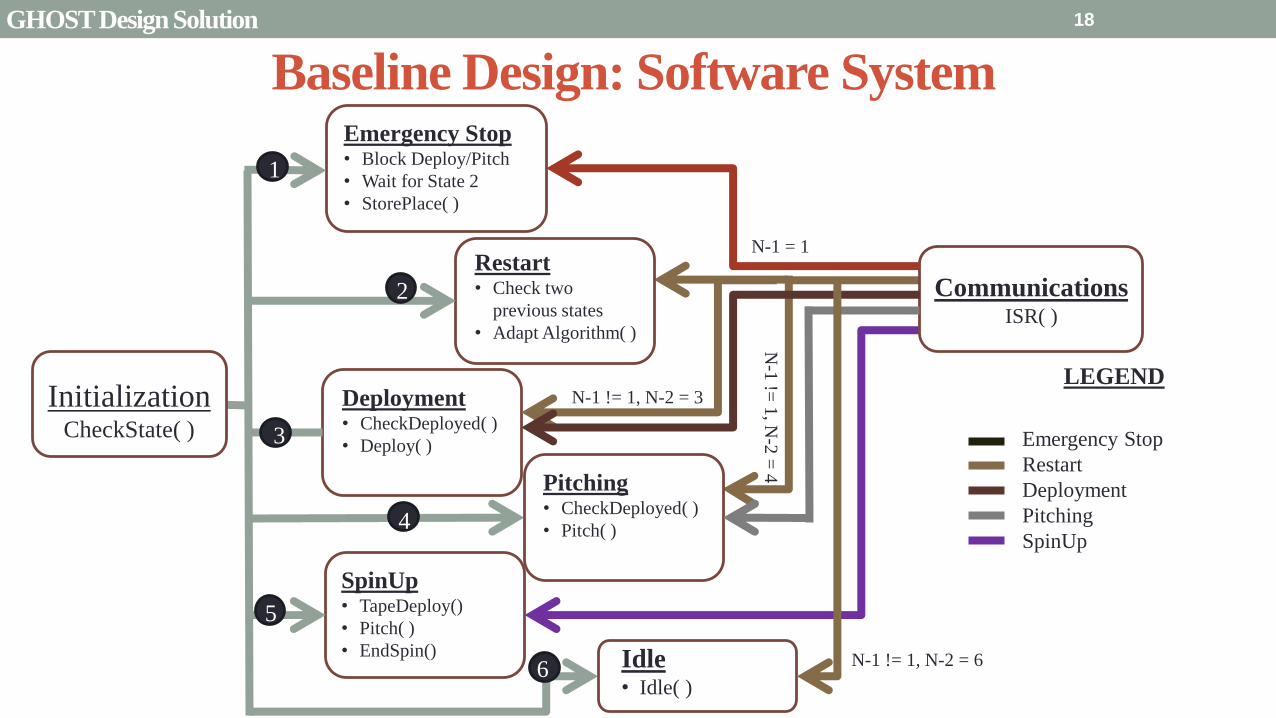
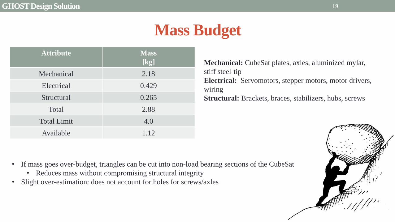
Mass Budget
Attribute Mass
[kg]
Mechanical 218
Electrical 0429
Structural 0265
Total 288
Total Limit 40
Available 112
Mechanical CubeSat plates axles aluminized mylar
stiff steel tip
Electrical Servomotors stepper motors motor drivers
wiring
Structural Brackets braces stabilizers hubs screws
bull If mass goes over-budget triangles can be cut into non-load bearing sections of the CubeSat
bull Reduces mass without compromising structural integrity
bull Slight over-estimation does not account for holes for screwsaxles
19 GHOST Design Solution
Power Budget Individual Components
Power Usage Number per
System
Supply Current
per System (A)
Supply
Voltage (V)
Power Subtotal
(maximum) (W)
Mission Phase
Launch Locks 2 -- 28 15 1
PIC18F87K22 1 001 5 005 1 2 3 4
Sanyo Stepper Motor 2 04 35 14 1 2 3 4
Driver DRV8834 2 1phase 5 5 1 2 3 4
Servomotor
FAULHABER 2036
2 02 5 10 2 4
Servomotor Driver 2 01 5 05 24
Encoder AU-
ZSD1000A
2 004 5
095
2 4
Mission Phase Description Power Budget Total Power Used
Pre-deployment (1) Stepper motor holds Launch Locks initiate unlock gt 10 W 2215 W
Initial Spin-Up (2) Stepper releases 5m stepper holds while pitching 10 W 91 W
Deployment (3) Stepper motor rotates to deploy blade 10 W 715 W
Pitch and Hold (4) Servomotor pitches blade root Stepper motor holds 10 W 91 W
20 GHOST Design Solution
Presentation Sections
bullPurpose and Objectives
bullGHOST Design Solution
bullCritical Project Elements
bullRequirement Satisfaction
bullRemaining Risks
bullVerification and Validation of Design
bullProject Planning
21
21
Critical Project Elements
bull Mechanical
bull Blade Deployment
bull Blade Reel Module can store a sufficiently sized solar sail blade
bull Sized such that will produce a minimum characteristic acceleration of 01 mms^2
bull Motor fits in Blade Reel Module and is capable of a controlled deployment rate of 1 to 10 cms
bull Pitch Actuation
bull Motor can actuate the Blade Reel Module plusmn 90deg
bull Central Module allows for a minimum of 2U (200 cm^3) storage for COMM EPS and scientific payload considerations
bull Structural Integrity
bull Structure can handle shear and tensile stresses present in space and 1G environment
bull Mitigates vibration of external modules on pitch axle and motor
bull Mass amp Volume Budgets
bull Mass and Volume limited by 6 kg and 6U (1 kgU)
22 CPEs
Critical Project Elements
bull Electrical bull MicrocontrollerDriverMotor Connection
bull Functional and wiring sufficiently sized to carry necessary current
bull Inter-module service loop connection
bull Thermal Considerations bull Pitch motor and electronics are sufficiently insulated andor heated by electrical coils
bull Electrical heat dissipation does not overheat internal components
bull Power Budget bull Power usage never exceeds 10 W
bull Software bull Algorithms
bull Integrated with electronics bull Language compatible with microcontroller
bull Capable of producing relevant pitch profiles to be used by pitch motor
bull Control initial deployment deployment rate and confirm deployment status
bull Memory Concerns bull Bus has necessary memory storage on board
23 CPEs
Critical Project Elements
bull Space Concerns
bull Launch Vibrations amp Survivability
bull Structural integrity uncompromised due to launch conditions
bull Launch Locks installed for launch vibration mitigation between external Blade Reel Modules and Internal
Central Module
bull Launch Lock design for support of sail blade tip
bull Canisterized Satellite Dispenser (CSD)
bull CubeSat meets specifications for use in dispenser
bull Initial Spin-Up
bull CubeSat induces rotation of its own accord
bull Use of stainless-steel reinforced sail material at blade tip
24 CPEs
Critical Project Elements
bull Manufacturing and Assembly bull Order of Manufacturing
bull Construction from outside-in
bull Wall Construction bull Thickness sufficient for structural needs and use of fasteners
bull Solar Sail bull Attachment to deployment axle in Blade Reel Module
bull Bonding of stainless-steel supports to sail material
bull Pitching Axle bull Connection between pitch motor and external Blade Reel Module
bull Satisfies tensile and shear stress concerns
bull Minimizes vibration between interfaces
bull Bearings
bull CSD Tabs bull Tabs implemented into construction to allow use in satellite dispenser
25 CPEs
Presentation Sections
bull Purpose and Objectives
bull GHOST Design Solution
bull Critical Project Elements
bull Requirement Satisfaction
bull Controlled Deployment Rate
bull Pitching
bull Survive Launch
bull ElectronicSoftware Integration
bull Manufacturing the CubeSat
bull Summary
bull Remaining Risks
bull Verification and Validation of Design
bull Project Planning
26
Initial Spin-Up
bull Problem Initially deploy solar sail straight without aid in centripetal forces
bull Hardened stainless-steel support attached along middle of last 5 m of Sail Membrane and acts as a ldquotape-measurerdquo
bull Properties of ldquotape measurerdquo bull Dim 5m x 2cm x 127μm
bull ρ = 7860 kgm3
bull m = 998 g
bull A maximum torque of 0147 mNmiddotm required by deployment motor
bull Conditions to reach Ω = 1 RPM
bull 120579119901119894119905119888ℎ = 35deg
bull ∆119905119904119901119894119899 119906119901= 184 days
Solar Blade
Steel Spine
CubeSat
Ω = 1 RPM
Rinitial = 5 m
F = 35 μN
27 Controlled Deployment Rate
Centripetal Acceleration
Deployment
Length
(m)
Centripetal
Acceleration
(ms2)
Sail
Mass
(kg)
Centripetal
Force (N)
5 0055 0014 74times10-5
100 11 0080 0088
200 22 015 033
300 33 022 072
400 44 029 127
500 55 036 197
545 58 038 217
28
Rotation Rate Ω = 1 RPM
Orbital Trajectory
Vtip
Ω
Controlled Deployment Rate
Fg
Fc
Fg is negligible
Space to Earth Comparison
29
CubeSat rotating at 1 RPM rarr centripetal acceleration rarr centrifugal tension
Blade is fully deployed rarr maximum centrifugal tension
Simulate same centrifugal tension the blade would experience in space
Total mass of 36 g used in the deployment test
mTotalSpace = 3775 g
F = 217 N
mTotalEarth = 119865
119892 = 2215 g
The holding torque of the motor used must be able to withstand this force
τ = r times F τ = 0011 Nm
Space Application
Motor
CubeSat
rotating at 1
RPM
Blade Tip mass
F
Top View
Tip mass trajectory
mTM = 2070 g
F = mg
Ground Deployment
r
Mounted to Table Side View
Tip
mass
Motor
Blade
Front View
MotorBus
Interface
Controlled Deployment Rate
Deployment Parts List Electronics Part Voltage (V) Current (A) Interface Dimensions (mm) Cost ($)
Sanyo Stepper Motor 35 03 Input 4 (bipolar) 42times42times11 60
DRV8834 Low-Voltage
Stepper Motor Driver
25-108 05phase Output 4
Input 8 (7 IO 1 CCP)
Power 2 (motor and logic)
Ground 2 (motor and logic)
15times20 10
30 Controlled Deployment Rate
Stepper Motor Stepper Motor Driver
Software Prototype
Deployment
Algorithm
bull Written in MATLAB to prove concept of deployment
bull Need to maintain constant deployment rate
Time Step Passes
Find Rotations Made in Time Step
Calculate Length Deployed
Find new Diameter and
Circumference
Calculate new Rotation Rate
Set Initial Diameter
and Circumference
Calculate Rotation
Rate
31 Controlled Deployment Rate
Presentation Sections
bull Purpose and Objectives
bull GHOST Design Solution
bull Critical Project Elements
bull Requirement Satisfaction
bull Controlled Deployment Rate
bull Pitching
bull Survive Launch
bull ElectronicSoftware Integration
bull Manufacturing the CubeSat
bull Summary
bull Remaining Risks
bull Verification and Validation of Design
bull Project Planning
32
The Need for plusmn 90deg Range of Pitch
Blade
Pitch θ
Condition (Profile Description)
0deg Max Thrust (Collective Blade Surface
Normal to Sunlight)
plusmn 35deg Max Torque (Collective) or Max In-Plane
Thrust (1P Cyclic)
plusmn 90deg No Thrust (Collective Blades Edge on to
Solar Wind)
Full 180deg range of motion for blade pitch necessary for spacecraft to have full capabilities of
controlling the thrust vector See Appendix for further information
33 Pitching
Pitching Parts List Electronics
Part Voltage (V) Current (A) Interface Dimensions (mm) Cost ($)
FAULHABER 2036
BLDC Motor
5 02 Input 3 phase
Sensors 3 HALL
Power 1
36times20 (diameter) 230
Atmel ATA6832-DK
Brushless DC Motor
Controller
5 01 Output 3 phase
Input 1 Serial 2 IO
45times45 208
2 Channel IE2-1024
Encoder
5 04 Output 4 I0
Power 1
165times15 (diameter) 225
34
2036 BLDC Motor
Pitching
Servo Controller
bull Bypass LIN input for direct interface with potentiometer
(Serial input use DAC from microcontroller)
35 Pitching
Pitching Software
Pitch Profile Command Sent
Find corresponding
sinusoid equation for pitching
Command servo to turn to angle in
pitching sinusoid
Compare to Encoder Angle
Given a pitch profile the software will
bull Find the corresponding sinusoid command for the
servos
bull Step through those angles over the time period
bull Compare commanded angle to encoder feedback
bull Adjust for accuracy
Pitching 36
Presentation Sections
bull Purpose and Objectives
bull GHOST Design Solution
bull Critical Project Elements
bull Requirement Satisfaction
bull Controlled Deployment Rate
bull Pitching
bull Survive Launch
bull ElectronicSoftware Integration
bull Manufacturing the CubeSat
bull Summary
bull Remaining Risks
bull Verification and Validation of Design
bull Project Planning
37
Canisterized Satellite Dispenser CSD
bull 6U fits into CSD during launch
bull Gives extra clearance on each side bull Allows for locking mechanism outside the 6U
bull Available with Alum 6061
bull Pushed into orbit on ldquoTabrdquo structure bull Additional tabs added below CubeSat base
bull Able to separate tabs for each separate section
38 Survive Launch
Structural Integrity of Pitching Axle and Selection of
Material
bull Aluminum 6061
bull Lightweight (density of 27gcc)
bull Very strong
bull Inexpensive
bull Pitching Axle ndash rod 1 cm in diameter
bull If made of Aluminum 6061
bull Can withstand shear force of 162 kN (~3600 lbs)
bull Does not take into account ability of motor to withstand torque
F (from Solar
Sail)
τ
39 Survive Launch
Pitching Axle
Launch Locks
bull Sierra Nevada SP-5025 pin puller
bull 350 lbf (1500 N) of shear load
bull Powered by a single timed power pulse to one of
the redundant heater circuits
bull SP -5025 greatly exceeds budget so manual
screw and bolt sized appropriately simulate
launch locks in the prototype
40
SP-5025
SP-5025
Deployed
Stowed
Simulated
Launch Locks
Survive Launch
Credit to SNC
Secure Blade Tip Mass
bull C-brackets attached to exterior walls stabilize tip mass vertically and horizontally
bull Cylindrical tip mass fits securely in brackets on both sides
bull Holding torque of stepper motor and tape-measure material holds tip mass in towards rolled blade
bull Within outer limit required by CSD
41
16 cm
075 cm 2 cm
Survive Launch
Presentation Sections
bull Purpose and Objectives
bull GHOST Design Solution
bull Critical Project Elements
bull Requirement Satisfaction
bull Controlled Deployment Rate
bull Pitching
bull Survive Launch
bull ElectronicsSoftware Integration
bull Manufacturing the CubeSat
bull Summary
bull Remaining Risks
bull Verification and Validation of Design
bull Project Planning
42
Service Loop
Power and input wires needed in for stepper
motor in deployment module
bull 4 12A rated wires AWG 21 D = 073 mm
bull Full loop around pitching axle to allow for
plusmn90deg rotational freedom
bull 1 cm diameter hole through each plate
bull Current must run throughout launch to
keep holding torque
bull Need not worry about freezing later in mission
Wires (red) exit opening in wall loops around
pitching axle enters opening in opposite wall
43 ElectronicsSoftware Integration
Electrical Block Diagram
Micro-
controller
35 V Supply
Stepper
Driver
Stepper
Motor
H4
H5
H3
H6
Key IO
CCP
Power
Serial
GND
Sensor
VDD
M0
M1
ENABLE
CONFIG
GND
DIR
STEP
E0
E2
B2
B1
A1
A2
VMOT GND VDD
5 V Supply
GND
Servo
Driver 1
Servo 1 TX RX
P G A B C
5V GND U V W Servo
Driver 2
Servo 2
P G A B C
5V GND C2 C3 C4 U V W
Encoder
J2 J3 J4 J5 J6 J7
VDC G
C0
(Speed Set)
C0
(Speed Set)
RS 232
DAC
A B C
Encoder VDC G A B C
B5 B4
A3
A7
B7
B6
D4
D3
D4 D3
C2 C3 C4
VoutA
VoutB
SCLK CS
DIN
GND
Tin Rout Vin GND
VDD
A4
SLEEP
FAULT H0
E1
44 ElectronicsSoftware Integration
Microcontroller PIC18F87K22
Board Requirements
bull Serial output for communication with computer
and servomotor controller
bullDAC used for servomotor communication
bull I0 ports for stepper driver interface
bull CCP port for stepper driver interface
bull Header pins for the encoder interface
Total
18 IO
1 CCP
1 TXRX
bull Would need more IO and CCP ports for a second
stepper motor driver
bull Unused ports 37 IO and 10 CCPECCP
ElectronicsSoftware Integration
PCB Design
bull 2 Layer Board
bull FR4 material
bull 1 oz Copper traces
bull Estimated Dimension = 5times5 cm
bull (See Appendix for Electrical Schematic)
EasyPIC PRO
v7 Pinout
80 Pin Development
Board
ElectronicsSoftware Integration
Incompatible Industrial Boards
Presentation Sections
bull Purpose and Objectives
bull GHOST Design Solution
bull Critical Project Elements
bull Requirement Satisfaction
bull Controlled Deployment Rate
bull Pitching
bull Survive Launch
bull ElectronicsSoftware Integration
bull Manufacturing the CubeSat
bull Summary
bull Remaining Risks
bull Verification and Validation of Design
bull Project Planning
47
Manufacturing In-House vs Purchasing
48
Part In-House Purchase Details
CubeSat walls Aluminum will be purchased with correct thickness and
manufactured to needed dimensions
Blade and pitching axle Axles can be cut down to needed length
Corner brackets Brackets can be altered to fit needed dimensions
S-brackets and C-brackets Will have to be machined to fit strict dimensions
Tip mass Tip mass can be cut down to needed length
Tape-measure material Purchased from McMaster-Carr
Solar sail blade material Blade material is provided for free by NASA LaRC
Launch Locks Launch locks we will use are a screw and bolt
Launch Tabs for CSD Tabs must meet strict dimensions to fit into CSD from
Planetary Systems Corporation
Hub to attach pitching axle to blade module Will have to be machined to meet needed dimensions
Screwsnutsbolts All can be purchased in various sizes and lengths
Motorsencoders and motor drivers All purchased to meet necessary requirements
Electronics board Will have to be made to accommodate needed electronics
Stabilizers to hold pitching motors Will have to be machined to properly fit around motors
Manufacturing the CubeSat
Assembly Procedure
49 Manufacturing the CubeSat
Bonding Mylar to Spool and Stiff Material
bull Loctite Super Glue Professional
bull Shear strength of 01 Nmm2
bull Cross-Sectional Area = 6575 mm2
bull Shear Stress = 33e-4 Nmm2
bull Blade will retain 4 rolls around axle at
final length
bull Loctite to bond stainless steel stiff
material to Mylar and to spool
F = mg = 217 N
Motor
Blade frac14 of roll glued
50 Manufacturing the CubeSat
Fixing Deployment Motor to S-Bracket
51
bull Deployment stepper motor is attached to S-bracket
bull S-bracket stabilized to back of blade deployment
module and vertical CubeSat walls
bull Motor is capable of being screwed directly to S-bracket
bull S-bracket has thickness of 18 inch
Holes for screws to
stabilize S-bracket
Hole for motor shaft
or press-fit ball
bearing to attach to
blade axle
Holes to screw motor
to S-bracket
Manufacturing the CubeSat
Pitching Axle Interfaces
bull Pitching axle to motor axle
bull Motor axle (smaller) fits into pitching
axle (larger) using set-screws
bull Pitching Axle to Blade Reel
Module
bull Axle fixed by set screws inside a hub
52
Pitching Axle
Hub
Motor Axle
4 Set Screws
Manufacturing the CubeSat
Presentation Sections
bull Purpose and Objectives
bull GHOST design solution
bull Critical Project Elements
bull Requirement Satisfaction
bull Controlled Deployment Rate
bull Pitching
bull Survive Launch
bull ElectronicSoftware Integration
bull Manufacturing the CubeSat
bull Summary
bull Remaining Risks and Mitigations
bull Verification and Validation of Design
bull Schedule and remaining work
53
Requirements Satisfaction
Aspect Requirement GHOST Specification
Mass 1 kgU 288 kg
Volume lt= 12U 6U
Life Span 4 months Greater than 4 months
Space Applicable
While design does not need to be
space worthy it should be applicable
to being used in space
All components are picked for
realistic use in space with minimal
cost parts and increased life span
54 Summary
Requirements Satisfaction
Aspect Requirement GHOST Specification
Characteristic Acceleration ac ge 01 mms2 ac = 03868 mms2
Sail Aspect Ratio AR ge 1001 AR = 38931
Sail Deployment Speed 1 cms le 10cms ~5 cms
Pitching Range Ability to pitch blades plusmn 90deg Ability to pitch blades plusmn 90deg
Pitching Coordination Multiple blade coordination when
pitching
Can pitch both blades at once either to
same angle or opposite angles
55 Summary
Presentation Sections
bullPurpose and Objectives
bullGHOST Design Solution
bullCritical Project Elements
bullRequirement Satisfaction
bullRemaining Risks
bullVerification and Validation of Design
bullProject Planning
56
Design Risks
Severity
Likelihood Marginal Major
Often Pitch angle error root not
following tip
Occasional Power loss COMM loss
Structural survivability
pitching motor failure
Improbable Small tear in Mylar Deploy too fast stowage
and deployment of Mylar
Axle failure
launch fail
space dust
deployment motor failure
57 Remaining Risks
Logistical Risks
Severity
Likelihood Minor Marginal Major
Often Parts delayed due to US
Postal Service
Occasional Structural consultation
unavailable
Ball vibrations test is not
available machine parts
not done on schedule
Government shutdown and
we canrsquot get Mylar or help
from NASA
Improbable No time for pitching test
High Bay in Fleming is
unavailable motors donrsquot
show up
58 Remaining Risks
Financial Risks
Severity
Likelihood Minor Marginal Major
Often Repurchase parts
Occasional Motor breaks Price of shake table
Improbable Hyper inflation
59 Remaining Risks
Presentation Sections
bullPurpose and Objectives
bullGHOST Design Solution
bullCritical Project Elements
bullRequirement Satisfaction
bullRemaining Risks
bullVerification and Validation of Design
bullProject Planning
60
Deployment System
Validate that the blade is deployed at a constant rate of 1-10 cms in a high bay
room
Verify that the motor can deploy at constant rate
Verify with test that the deployment system does not use more than the maximum power available of 10W
Validate that the blade can successfully deploy a blade with tape measure
material at a constant rate along ground
Verify with demonstration that the tape measure material can extend length of
blade
Verification and Validation
Verification and Validation
61
Blade Deployment Testing Information
bull Location Prof Frewrsquos High Bay Lab
bull Scheduled MarchApril with late night access to avoid
scheduling conflicts
bull Measurement Tape measure for distance and video
camera for time
bull Power Delivered 6253A Dual DC Power Supply
delivers 0-20 V and 0-3A
Tape measure
marking
distance up
wall
Kinematic Model
bull Torque from motor drives a constant velocity deployment
120591119898119900119905119900119903 = 120591119903119900119897119897 + 120591119901119906119904ℎ119894119899119892 119879119872 minus 120591119892119903119886119907119894119905119910 119879119872
120591119903119900119897119897 =119889119868119903119900119897119897
119889119905120596119903119900119897119897 + 119868119903119900119897119897
119889120596119903119900119897119897
119889119905
120591119901119906119904ℎ119894119899119892 119879119872 =119889119898119890119909119905
119889119905119903119903119900119897119897119907 + 119898119890119909119905
119889119903119903119900119897119897
119889119905119907
120591119892119903119886119907119894119905119910 119879119872 = 119898119890119909119905119903119903119900119897119897119892 bull 120649119945119952119949119941119946119951119944 = 120782 120782120790120787 N∙m 120649119950119952119941119942119949119950119938119961 = 120782 120782120782120789 N∙m
Power Supply
Verification and Validation
CubeSat Wire
62
Pitching System
Validate that the blade reel modules experience coordinated pitching
Verify that one blade reel module experiences periodic
motion
Verify that the blade reel module rotates to 0deg upon
initialization
Verify that the blade pitches to a given command
angle
Verify that the motorencoder system does not exceed power
available
Verification and Validation
Verification and Validation
63
Verify Pitching Angle Experiment Equipment and Specs
bull Use R60D RVIT (Rotary Variable Inductance Transducer) sensor to measure angles attaches to pin (red) in line with pitching axis bull Measures ranges of plusmn60deg rotation
bull Input Voltage = plusmn15 V
bull Output Voltage = plusmn75 V
bull Resolution = 0125 Vdeg
bull 119891119898119886119909 = 20 Hz
bull Use AD524 Precision Amplifier Instrumentation for signal conditioning bull Input Voltage plusmn10 V
bull Output Voltage plusmn10V
bull Requires Supply Voltage plusmn15
bull Use NI 9201 bull Input Voltage plusmn10 V
bull Has a USB output that can connect to a computer where vi program records
Experiment Set-Up
R60D RVIT
AD524
NI 9201 PC via USB
Verification and Validation 64
Verify Periodic Motion Experiment
bull Using the R60D RVIT set-up to measure deflection angles
bull With data of the angle deflection 120579 angular velocity 120596 and angular acceleration 120572 can be measured bull Motor restriction 120591119898119886119909 = 032 Nmiddotm
bull Model restriction 120596119898119886119909 = Ω2 if Ω = 2rpm 120596119898119886119909 = 02094 rads
Validation Model
bull R60D RVIT measures plusmn60deg deflection angles bull Critical condition blade reel module pitches plusmn90deg Ω=2rpm
bull 120572119888 = 00172 rads2 and 120596119898 = 0164 rads thus 120591119898 = 0083 mNmiddotm (119868119898119900119889 = 00048 kgmiddotm2)
120579 119905 120596 119905 120572 119905
Verification and Validation 65
Verification and Validation
Structural System
Validate that the final design can survive launch by using a shake
table
Verify the structural integrity by demonstrating that all stationary parts are
static
Verification and Validation 66
Trade Study FEM vs Vibration Table
Cost Time Experience
Similar to
Actual
Launch
Guaranteed Can
Do Total
FEM 4 1 1 3 4 215
Vibration
Table 2 3 4 4 2 32
Weight () 5 30 25 20 20 100
67 Verification and Validation
See Appendix for Full Trade Study
Validate Structural Stability
bull Will use a shaker table from Ball Aerospace
bull Cost = $250hr
bull Schedule Time to be determined in April
bull Specifications Peak vibration occurs with 34g at
frequency of 16 Hz (Saturn V)
bull Will be verified by examining the structural integrity
of the manufacturing
Verification and Validation 68
CubeSat
Shake Table
Presentation Sections
bullPurpose and Objectives
bullGHOST Design Solution
bullCritical Project Elements
bullRequirement Satisfaction
bullRemaining Risks
bullVerification and Validation of Design
bullProject Planning
69
Organizational Chart
Mark
Dolezal
Emily
Proano
Lauren
Persons
Casey
Myers
Nicholas
Busbey
Taylor
Smith
Karynna
Tuan
Megan
Scheele
Project
Manager
Software
Lead
Electrical
Lead
Systems Test and
Safety
Manufacturing
Lead Mechanics
Lead
CFO and
Materials
Lead
Organizing
team
meetings
Supporting
other leads
Non CPE
Tasks
Deployment
Control
Pitching
Control Motors and
Electronics
Power
Integrate
all system Perform
and Plan
tests
Manufacture
all in-house
parts
SolidWorks
Keep track
of financial
spending
Right
materials
are being
utilized
CubeSat
Assembly
Specific
System
Requirements
70 Project Planning
GHOST
Materials Mechanical Electrical Software Documents
Shake Table
Vibration
Analysis
Mechanical
Layout
Power Budget Pitch Control
Algorithm
Deployment
Rate Control
Algorithm SolidWorks
Model
Electrical
Wiring Layout
Thermodynamic
Analysis of
Electronic System
Mass Budget
Prototype of
CubeSat Bus
Motor
Subsystem
CDR
FFR
Spring
Schedule
Financial
Budget
Work Breakdown Structure (WBS)
Mylar from
NASA
Spin Up
Algorithm
Emergency
StopRestart System
71 Project Planning
PCB Design
Spring
Documents
113 120 127 203 210 217 224 303 310 317 324 331 407 414 421 428
MSR TRR SFR PFR
Time (date)
Purchase
motorsdrivers
Preliminary code
Electronic
integration
Test code
Electronicscode
interface
Purchase
raw materials
Manufacture frame
Assemble bus
Manufacture
remaining parts
Integrate system
Deployment test
Pitching test
Vibration test
Ta
sks
72
GHOST Spring Schedule
Project Planning
Planned Uncertainty
Key
Test Plan Test Scheduled Facility Specialized Equipment
Verify Pitch Angle 317 ITLL R60D RVIT NI 9201 AD524 Oscilloscope bench
power source
Zero Pitch Angle 317 ITLL R60D RVIT NI 9201 AD524 Oscilloscope bench
power source
Measure power used in
pitchdeployment 317 ITLL Ammeter voltmeter bench power source
Verify constant deployment 324 ITLL Firewire camera bench power source
ASEN2003BallTrackervi
Verify periodic motion 324 ITLL R60D RVIT NI 9201 AD524 Oscilloscope bench
power source
Validate tape measure ground
deployment 331 ITLL
Bench power source tape measure stop watch rollers
for tip mass
Validate coordinated pitching 331 ITLL R60D RVIT NI 9201 AD524 oscilloscope bench
power source
Validate 1g blade deployment 331-414 Prof Frew
high bay
Portable 6253A Dual DC Power Supply ladder tape
measure video camera
Validate launch ready 414 Ball Aero Shake Table
Project Planning 73
Cost Table ndash Structural Components
Part Price per
part NeededVolume Needed Total Price Supplier
Aluminum 6061 Sheet
(18rdquo thick) $ 8976 2ft times 2ft times 18 in $ 8976 The Metals Depot
Aluminum 6061 rod
(14 in diameter) $280 2 ft $280 The Metals Depot
Aluminum6061 rod
(716 in diameter) $494 2 ft $494 The Metals Depot
Steel Corner Brackets
(34rdquo times 12rdquo)
$197 4
braces 16 $788 Home Depot
Hardened 302 Stainless
Steel $3300 2 cm times 5 m times 127 microm $3300 McMaster-Carr
Total $11834
74 Project Planning
Cost Table ndash Electrical Components
Part Price per
part Needed Total Price Supplier
Sanyo Stepper Motor $ 5995 2 $11990 Pololu Electronics and Robotics
DRV8834 Low-Voltage Stepper
Motor Driver $995 2 $1990 Pololu Electronics and Robotics
FAULHABER 2036 BLDC
Servo Motor $23000 2 $46000 MicroMo Micro Motion Solutions
Atmel ATA6832-DK Brushless
DC Motor Controller $20800 2 $41600 Atmel
Encoder AU-ZSD1000A $22500 2 $45000 MicroMo Micro Motion Solutions
PIC18F87K22 Microcontroller $500 1 $500 Microchip
AD-524 Signal Converter $1767 1 $1767 Agilent
Total $148847
75 Project Planning
Questions
76
References
bull wwwloctiteproductscom
bull Vallado D A Fundamentals of Astrodynamics and Applications
bull Guerrant D Lawrence D Heaton A Earth Escape Capabilities of the Heliogyro Sail AIAA Paper
bull wwwspaceflightnowcom
bull Guerrant D HGVizGuim MATLAB Program
bull httpwwwmicromocombrushless-dc-motorsaspx
bull httpwwwfaulhabercomservletcomitmrwawservletAnzeigefremdaufruf=jaampkdid=40929ampsprachid=1amphtdigurl=n169933i95222html
bull httpwwwpololucom
bull httpasmmatwebcomsearchSpecificMaterialaspbassnum=MA6061t6
bull httpwwwruagcomthermalSpace_Thermal_HardwareMulti_Layer_Insulation
bull Helgesen Bryan Sierra Nevada Corporation
77
GyroSail Launch Configuration and Deployment Sequence
78
1 Launch configuration (6U) 2 Blade reel modules pitch to zero Fits within a 6U or 12U dispenser
3 PV arrays deploy
Other array configurations are possible
williamkwilkienasagov NASA PREDECISIONAL - FOR DISCUSSION PURPOSES ONLY
78 Appendix
GyroSail Primary Bus Systems Based on modified JPLU MichUCLACal PolyUT INSPIRE bus
williamkwilkienasagov
05U cold gas thruster ACS for detumbling
and initial spin-up
(httpwwwaustinsatnet)
05U EPS battery CampDH UHF backup
comms (U Mich) 05U DSN-compatible X-band
communications (JPL)
05U COTS star trackerimager ADC (BCT) sail
module processor (CU)
Klesh A et al 2013 ldquoINSPIRE Interplanetary NanoSpacecraft Pathfinder In Relevant Environmentrdquo Proceedings of the AIAAUSU Conference on Small Satellites Around the Corner SSC13-
XI-8 httpdigitalcommonsusuedusmallsat2013all2013127
NASA PREDECISIONAL - FOR DISCUSSION PURPOSES ONLY
79 Appendix
COMM Subsystem
bull 18 m Ka-band antennas at White
Sands New Mexico
bull Goddard Space Flight Center
Greebelt Maryland USA
supplied the Mulemba Space
Center in Angola
80 Appendix
Orion Crew
Module
6U Canisterized Satellite
Dispenser (CSD) ESPA Ring
Spacecraft
Adapter
Interim Cryogenic Propulsion
Stage (ICPS)
Secondary Payload Attachment to SLS
The SLS design is currently going through CDR An ESPA
ring is not currently in place but is mentioned in the SLS
CONOPS in order to accommodate secondary payloads
81 Appendix
Max Thrust Condition Collective 90deg pitch profile
Max thrust normal to orbital plane
(Halo orbits orbital plane rotation ie
inclination change)
82
Credit to Dan Guerrant
Appendix
Max Thrust Condition
F vs β M vs β
83
Credit to Dan Guerrant
Appendix
No Thrust Condition Collective 0deg pitch profile
Zero thrust
84
Credit to Dan Guerrant
Appendix
No Thrust Condition
F vs β M vs β
85
Credit to Dan Guerrant
Appendix
Max Torque Condition Collective 35deg pitch profile
Max torque used for spinning up sc
(opposite orientation for despinning)
86
Credit to Dan Guerrant
Appendix
Max Torque Condition
F vs β M vs β
87
Credit to Dan Guerrant
Appendix
Max In-Plane Thrust Condition Cyclic 35deg pitch profile
Max thrust in in-plane (d2) direction for orbit raising
88
Credit to Dan Guerrant
Appendix
Max In-Plane Thrust Condition
F vs β M vs β
89
Credit to Dan Guerrant
Appendix
Orbit Raising
F
90 Appendix
Thermal Space Concerns
bull Material Concerns
bull Aluminum 6061 -196 degC to 160deg C
bull Electronics Concerns
bull Typical Operating Temperature -55 to 80 degC
bull Countermeasures
bull Multi-layer Insulation AAErotherm S10-190
bull (0005 ndash 0035 Wm2K)
bull Battery operated heaters for pre-sail deployment
Multi-layer Insulation
Layer 1 1 x Outer layer
Layer 2 8 x 03 mil VDAPolyimideVDA perf
8 x Woven Polyester netting
Layer 3 1 x Outer layer
Layer 4 1 x Woven Polyester netting
91 Appendix
Rolled Up Blade Reel Calculation Optimal Sail Length 545 m ndash Sail chord of 14 cm
Max Diameter of Spool 598 cm
Diameter of Axle 05 cm
Length of Stiff Material 5 m
Dimension of Stiff Material 5 m times 2 cm times 127 microm
92 Appendix
Torque calculation
bull Note current calculated via T=kI (where T is torque I is amp k is the torque
constant specific to the motor)
T = kI
(k = 005 NmA)
93 Appendix
Servo Controller
94 Appendix
Encoder Dimensions and Interface
bull FAULHABER IE2-1024
95 Appendix
Stepper Motor Torque
96 Appendix
Motor Phases (Stepper)
97 Appendix
98 Appendix
99 Appendix
100 Appendix
101 Appendix
Microcontroller
102 Appendix
ATA6832 Phase Output Chip
103 Appendix
ATA6624 Bypassed Chip
bull Bypassed chip
on servo controller
104 Appendix
Power Budget
105 Appendix
Wire Gauge
bull Stepper Motor 26AWG (04 mm diameter)
bull Servomotor 24 AWG (051 mm diameter)
bull Encoder 24 AWG
Voltage Drop () AWG Max Gauge
001 5
01 15
1 25
5 32
NOTE Voltage drop calculated at 1A and 40 cm of wire
106
24 AWG Wire
Appendix
Trade Study ndash FEM vs Vibration Table
Factor 4 3 2 1
Cost No money 0 gt C gt $100 $100 gt C gt $300 $300 lt C
Time 0 min lt T lt 30 min 30 min lt T lt 2 hrs 2 hrs lt T lt 1 day 1day lt T
Experience Everyone has
experience
A couple people
know how to
1 person has
experience
No one has
experience
Similar To Actual
Launch Simulate real launch
Doesnrsquot have all
variables experienced
Has only a couple
similarities
No similarities to
launch
Guaranteed Can Do
Donrsquot need any
outside equipment or
help
Need outside
equipment but
guaranteed use
Need outside
equipment but own
work at higher
priority
Need outside
equipment but canrsquot
use
Scoring
107 Appendix
Weighting
Weight () Category Reasoning
5 Cost Have a lot of extra $ in the budget
30 Time Have a strict schedule but not a main focus of the
project
25 Experience If no one has experience it will take a lot of time
20 Similar to Actual Launch Needs to be like actual launch
20 Guaranteed Can Do Needs to be able to accomplish but not the most
important focus
108 Appendix
Finite Element Method (FEM)
Objectives Description ProCon
Cost No money because one of us
would do it Pro
Time A lot of time to learn and then
perform FEM Con
Experience No one in group has FEM
experience Con
Similar to Actual Launch Very similar to actual launch Pro
Guaranteed Can Do All we need is paper pen and
theory to do Pro
109 Appendix
Vibration Table
Objective Description ProCons
Cost $250hr Con
Time A hour on the table should simulate
launch Pro
Experience Donrsquot need experience to run
vibration table Pro
Similar to Actual Launch Actually putting our system through
vibration stress Pro
Guaranteed Can Do No guarantee but most likely can Con
110 Appendix
SpinUp State
1 Check value of SpinUp to see if satellite is already spun up
bull Continue if satellite is not already spun-up
2 Deploy the tape stiffened length of the blade
3 Pitch to the spin up angle
4 Wait until characteristic angular velocity is reached
5 Pitch to pre-deployment position
6 Save SpinUp as completed
Appendix 111
Deployment State
1 Check if satellite has been spun up yet
bull Continue if it has
2 Check if blades are already deployed
bull Continue if they havenrsquot
3 Run deploy algorithm until blades are fully deployed
4 Save value saying blades have been deployed
Appendix 112
Pitching State
1 Check if satellite has been spun up
bull Continue if satellite has been spun up
2 Check if blades have been deployed
bull Continue if blades have been deployed
3 Look at commanded pitch profile
4 Find correlated sinusoid command
5 Command servo to pitch angle for the time in the orbit
6 Continue until given a new pitch command
Appendix 113
Emergency Stop
1 Save which state was interrupted
2 Save last position in interrupted
state
3 Wait until Restart command is
received
1 Check two previous states to see
what is being restarted
2 Look at saved last position in
state being restarted
3 Adapt the algorithm of the state
to continue where left off
Restart
Appendix 114
Comparison with Previous Heliogyro Concepts MIT (1989) NASA (2011) GHOST
Total sail craft mass (kg) 18 84
288 (6)
Characteristic acceleration ac
(mms2) 06 10 03868 (01854)
Sail reflective area (m2) 1200 960 1526
Non-sail mass (kg) 5 5 --
Number of sail blades 8 6 2
Blade chord (m) 15 08 014
Blade length (m) 100 200 545
Rotational period (minutes) 3 3 1
Blade root stress (Pa) 8650 34000 --
Blade root allowable stress (Pa) 55 M 55 M --
Blade root tension load (N) 01 007 --
115 Appendix
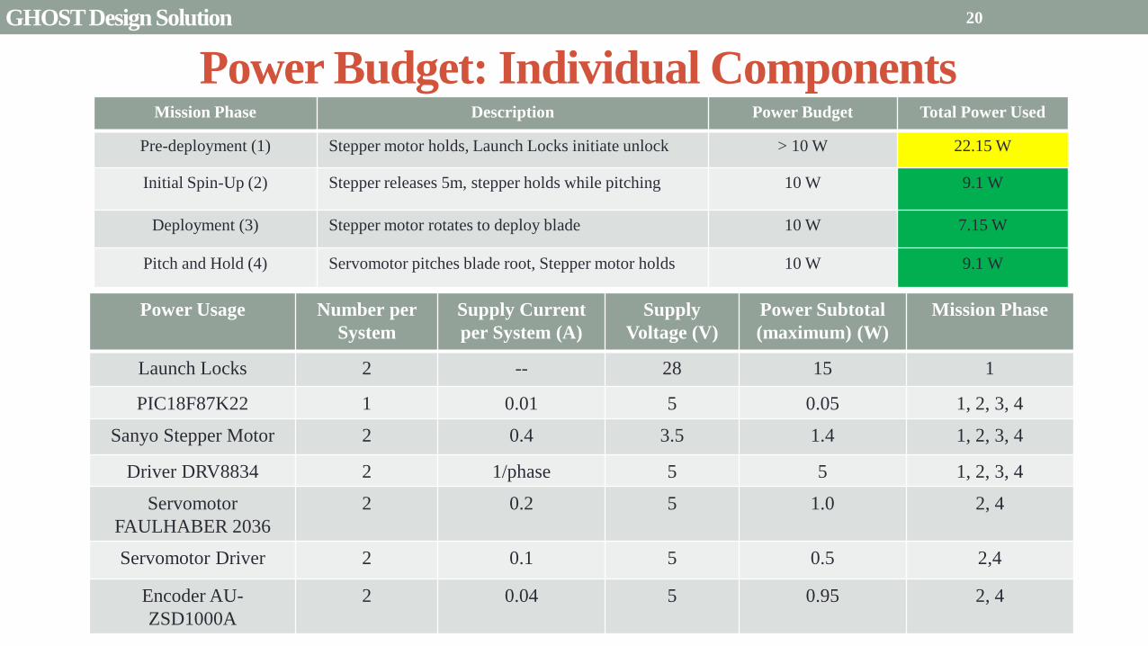
Presentation Sections
bullPurpose and Objectives
bullGHOST Design Solution
bullCritical Project Elements
bullRequirement Satisfaction
bullRemaining Risks
bullVerification and Validation of Design
bullProject Planning
21
21
Critical Project Elements
bull Mechanical
bull Blade Deployment
bull Blade Reel Module can store a sufficiently sized solar sail blade
bull Sized such that will produce a minimum characteristic acceleration of 01 mms^2
bull Motor fits in Blade Reel Module and is capable of a controlled deployment rate of 1 to 10 cms
bull Pitch Actuation
bull Motor can actuate the Blade Reel Module plusmn 90deg
bull Central Module allows for a minimum of 2U (200 cm^3) storage for COMM EPS and scientific payload considerations
bull Structural Integrity
bull Structure can handle shear and tensile stresses present in space and 1G environment
bull Mitigates vibration of external modules on pitch axle and motor
bull Mass amp Volume Budgets
bull Mass and Volume limited by 6 kg and 6U (1 kgU)
22 CPEs
Critical Project Elements
bull Electrical bull MicrocontrollerDriverMotor Connection
bull Functional and wiring sufficiently sized to carry necessary current
bull Inter-module service loop connection
bull Thermal Considerations bull Pitch motor and electronics are sufficiently insulated andor heated by electrical coils
bull Electrical heat dissipation does not overheat internal components
bull Power Budget bull Power usage never exceeds 10 W
bull Software bull Algorithms
bull Integrated with electronics bull Language compatible with microcontroller
bull Capable of producing relevant pitch profiles to be used by pitch motor
bull Control initial deployment deployment rate and confirm deployment status
bull Memory Concerns bull Bus has necessary memory storage on board
23 CPEs
Critical Project Elements
bull Space Concerns
bull Launch Vibrations amp Survivability
bull Structural integrity uncompromised due to launch conditions
bull Launch Locks installed for launch vibration mitigation between external Blade Reel Modules and Internal
Central Module
bull Launch Lock design for support of sail blade tip
bull Canisterized Satellite Dispenser (CSD)
bull CubeSat meets specifications for use in dispenser
bull Initial Spin-Up
bull CubeSat induces rotation of its own accord
bull Use of stainless-steel reinforced sail material at blade tip
24 CPEs
Critical Project Elements
bull Manufacturing and Assembly bull Order of Manufacturing
bull Construction from outside-in
bull Wall Construction bull Thickness sufficient for structural needs and use of fasteners
bull Solar Sail bull Attachment to deployment axle in Blade Reel Module
bull Bonding of stainless-steel supports to sail material
bull Pitching Axle bull Connection between pitch motor and external Blade Reel Module
bull Satisfies tensile and shear stress concerns
bull Minimizes vibration between interfaces
bull Bearings
bull CSD Tabs bull Tabs implemented into construction to allow use in satellite dispenser
25 CPEs
Presentation Sections
bull Purpose and Objectives
bull GHOST Design Solution
bull Critical Project Elements
bull Requirement Satisfaction
bull Controlled Deployment Rate
bull Pitching
bull Survive Launch
bull ElectronicSoftware Integration
bull Manufacturing the CubeSat
bull Summary
bull Remaining Risks
bull Verification and Validation of Design
bull Project Planning
26
Initial Spin-Up
bull Problem Initially deploy solar sail straight without aid in centripetal forces
bull Hardened stainless-steel support attached along middle of last 5 m of Sail Membrane and acts as a ldquotape-measurerdquo
bull Properties of ldquotape measurerdquo bull Dim 5m x 2cm x 127μm
bull ρ = 7860 kgm3
bull m = 998 g
bull A maximum torque of 0147 mNmiddotm required by deployment motor
bull Conditions to reach Ω = 1 RPM
bull 120579119901119894119905119888ℎ = 35deg
bull ∆119905119904119901119894119899 119906119901= 184 days
Solar Blade
Steel Spine
CubeSat
Ω = 1 RPM
Rinitial = 5 m
F = 35 μN
27 Controlled Deployment Rate
Centripetal Acceleration
Deployment
Length
(m)
Centripetal
Acceleration
(ms2)
Sail
Mass
(kg)
Centripetal
Force (N)
5 0055 0014 74times10-5
100 11 0080 0088
200 22 015 033
300 33 022 072
400 44 029 127
500 55 036 197
545 58 038 217
28
Rotation Rate Ω = 1 RPM
Orbital Trajectory
Vtip
Ω
Controlled Deployment Rate
Fg
Fc
Fg is negligible
Space to Earth Comparison
29
CubeSat rotating at 1 RPM rarr centripetal acceleration rarr centrifugal tension
Blade is fully deployed rarr maximum centrifugal tension
Simulate same centrifugal tension the blade would experience in space
Total mass of 36 g used in the deployment test
mTotalSpace = 3775 g
F = 217 N
mTotalEarth = 119865
119892 = 2215 g
The holding torque of the motor used must be able to withstand this force
τ = r times F τ = 0011 Nm
Space Application
Motor
CubeSat
rotating at 1
RPM
Blade Tip mass
F
Top View
Tip mass trajectory
mTM = 2070 g
F = mg
Ground Deployment
r
Mounted to Table Side View
Tip
mass
Motor
Blade
Front View
MotorBus
Interface
Controlled Deployment Rate
Deployment Parts List Electronics Part Voltage (V) Current (A) Interface Dimensions (mm) Cost ($)
Sanyo Stepper Motor 35 03 Input 4 (bipolar) 42times42times11 60
DRV8834 Low-Voltage
Stepper Motor Driver
25-108 05phase Output 4
Input 8 (7 IO 1 CCP)
Power 2 (motor and logic)
Ground 2 (motor and logic)
15times20 10
30 Controlled Deployment Rate
Stepper Motor Stepper Motor Driver
Software Prototype
Deployment
Algorithm
bull Written in MATLAB to prove concept of deployment
bull Need to maintain constant deployment rate
Time Step Passes
Find Rotations Made in Time Step
Calculate Length Deployed
Find new Diameter and
Circumference
Calculate new Rotation Rate
Set Initial Diameter
and Circumference
Calculate Rotation
Rate
31 Controlled Deployment Rate
Presentation Sections
bull Purpose and Objectives
bull GHOST Design Solution
bull Critical Project Elements
bull Requirement Satisfaction
bull Controlled Deployment Rate
bull Pitching
bull Survive Launch
bull ElectronicSoftware Integration
bull Manufacturing the CubeSat
bull Summary
bull Remaining Risks
bull Verification and Validation of Design
bull Project Planning
32
The Need for plusmn 90deg Range of Pitch
Blade
Pitch θ
Condition (Profile Description)
0deg Max Thrust (Collective Blade Surface
Normal to Sunlight)
plusmn 35deg Max Torque (Collective) or Max In-Plane
Thrust (1P Cyclic)
plusmn 90deg No Thrust (Collective Blades Edge on to
Solar Wind)
Full 180deg range of motion for blade pitch necessary for spacecraft to have full capabilities of
controlling the thrust vector See Appendix for further information
33 Pitching
Pitching Parts List Electronics
Part Voltage (V) Current (A) Interface Dimensions (mm) Cost ($)
FAULHABER 2036
BLDC Motor
5 02 Input 3 phase
Sensors 3 HALL
Power 1
36times20 (diameter) 230
Atmel ATA6832-DK
Brushless DC Motor
Controller
5 01 Output 3 phase
Input 1 Serial 2 IO
45times45 208
2 Channel IE2-1024
Encoder
5 04 Output 4 I0
Power 1
165times15 (diameter) 225
34
2036 BLDC Motor
Pitching
Servo Controller
bull Bypass LIN input for direct interface with potentiometer
(Serial input use DAC from microcontroller)
35 Pitching
Pitching Software
Pitch Profile Command Sent
Find corresponding
sinusoid equation for pitching
Command servo to turn to angle in
pitching sinusoid
Compare to Encoder Angle
Given a pitch profile the software will
bull Find the corresponding sinusoid command for the
servos
bull Step through those angles over the time period
bull Compare commanded angle to encoder feedback
bull Adjust for accuracy
Pitching 36
Presentation Sections
bull Purpose and Objectives
bull GHOST Design Solution
bull Critical Project Elements
bull Requirement Satisfaction
bull Controlled Deployment Rate
bull Pitching
bull Survive Launch
bull ElectronicSoftware Integration
bull Manufacturing the CubeSat
bull Summary
bull Remaining Risks
bull Verification and Validation of Design
bull Project Planning
37
Canisterized Satellite Dispenser CSD
bull 6U fits into CSD during launch
bull Gives extra clearance on each side bull Allows for locking mechanism outside the 6U
bull Available with Alum 6061
bull Pushed into orbit on ldquoTabrdquo structure bull Additional tabs added below CubeSat base
bull Able to separate tabs for each separate section
38 Survive Launch
Structural Integrity of Pitching Axle and Selection of
Material
bull Aluminum 6061
bull Lightweight (density of 27gcc)
bull Very strong
bull Inexpensive
bull Pitching Axle ndash rod 1 cm in diameter
bull If made of Aluminum 6061
bull Can withstand shear force of 162 kN (~3600 lbs)
bull Does not take into account ability of motor to withstand torque
F (from Solar
Sail)
τ
39 Survive Launch
Pitching Axle
Launch Locks
bull Sierra Nevada SP-5025 pin puller
bull 350 lbf (1500 N) of shear load
bull Powered by a single timed power pulse to one of
the redundant heater circuits
bull SP -5025 greatly exceeds budget so manual
screw and bolt sized appropriately simulate
launch locks in the prototype
40
SP-5025
SP-5025
Deployed
Stowed
Simulated
Launch Locks
Survive Launch
Credit to SNC
Secure Blade Tip Mass
bull C-brackets attached to exterior walls stabilize tip mass vertically and horizontally
bull Cylindrical tip mass fits securely in brackets on both sides
bull Holding torque of stepper motor and tape-measure material holds tip mass in towards rolled blade
bull Within outer limit required by CSD
41
16 cm
075 cm 2 cm
Survive Launch
Presentation Sections
bull Purpose and Objectives
bull GHOST Design Solution
bull Critical Project Elements
bull Requirement Satisfaction
bull Controlled Deployment Rate
bull Pitching
bull Survive Launch
bull ElectronicsSoftware Integration
bull Manufacturing the CubeSat
bull Summary
bull Remaining Risks
bull Verification and Validation of Design
bull Project Planning
42
Service Loop
Power and input wires needed in for stepper
motor in deployment module
bull 4 12A rated wires AWG 21 D = 073 mm
bull Full loop around pitching axle to allow for
plusmn90deg rotational freedom
bull 1 cm diameter hole through each plate
bull Current must run throughout launch to
keep holding torque
bull Need not worry about freezing later in mission
Wires (red) exit opening in wall loops around
pitching axle enters opening in opposite wall
43 ElectronicsSoftware Integration
Electrical Block Diagram
Micro-
controller
35 V Supply
Stepper
Driver
Stepper
Motor
H4
H5
H3
H6
Key IO
CCP
Power
Serial
GND
Sensor
VDD
M0
M1
ENABLE
CONFIG
GND
DIR
STEP
E0
E2
B2
B1
A1
A2
VMOT GND VDD
5 V Supply
GND
Servo
Driver 1
Servo 1 TX RX
P G A B C
5V GND U V W Servo
Driver 2
Servo 2
P G A B C
5V GND C2 C3 C4 U V W
Encoder
J2 J3 J4 J5 J6 J7
VDC G
C0
(Speed Set)
C0
(Speed Set)
RS 232
DAC
A B C
Encoder VDC G A B C
B5 B4
A3
A7
B7
B6
D4
D3
D4 D3
C2 C3 C4
VoutA
VoutB
SCLK CS
DIN
GND
Tin Rout Vin GND
VDD
A4
SLEEP
FAULT H0
E1
44 ElectronicsSoftware Integration
Microcontroller PIC18F87K22
Board Requirements
bull Serial output for communication with computer
and servomotor controller
bullDAC used for servomotor communication
bull I0 ports for stepper driver interface
bull CCP port for stepper driver interface
bull Header pins for the encoder interface
Total
18 IO
1 CCP
1 TXRX
bull Would need more IO and CCP ports for a second
stepper motor driver
bull Unused ports 37 IO and 10 CCPECCP
ElectronicsSoftware Integration
PCB Design
bull 2 Layer Board
bull FR4 material
bull 1 oz Copper traces
bull Estimated Dimension = 5times5 cm
bull (See Appendix for Electrical Schematic)
EasyPIC PRO
v7 Pinout
80 Pin Development
Board
ElectronicsSoftware Integration
Incompatible Industrial Boards
Presentation Sections
bull Purpose and Objectives
bull GHOST Design Solution
bull Critical Project Elements
bull Requirement Satisfaction
bull Controlled Deployment Rate
bull Pitching
bull Survive Launch
bull ElectronicsSoftware Integration
bull Manufacturing the CubeSat
bull Summary
bull Remaining Risks
bull Verification and Validation of Design
bull Project Planning
47
Manufacturing In-House vs Purchasing
48
Part In-House Purchase Details
CubeSat walls Aluminum will be purchased with correct thickness and
manufactured to needed dimensions
Blade and pitching axle Axles can be cut down to needed length
Corner brackets Brackets can be altered to fit needed dimensions
S-brackets and C-brackets Will have to be machined to fit strict dimensions
Tip mass Tip mass can be cut down to needed length
Tape-measure material Purchased from McMaster-Carr
Solar sail blade material Blade material is provided for free by NASA LaRC
Launch Locks Launch locks we will use are a screw and bolt
Launch Tabs for CSD Tabs must meet strict dimensions to fit into CSD from
Planetary Systems Corporation
Hub to attach pitching axle to blade module Will have to be machined to meet needed dimensions
Screwsnutsbolts All can be purchased in various sizes and lengths
Motorsencoders and motor drivers All purchased to meet necessary requirements
Electronics board Will have to be made to accommodate needed electronics
Stabilizers to hold pitching motors Will have to be machined to properly fit around motors
Manufacturing the CubeSat
Assembly Procedure
49 Manufacturing the CubeSat
Bonding Mylar to Spool and Stiff Material
bull Loctite Super Glue Professional
bull Shear strength of 01 Nmm2
bull Cross-Sectional Area = 6575 mm2
bull Shear Stress = 33e-4 Nmm2
bull Blade will retain 4 rolls around axle at
final length
bull Loctite to bond stainless steel stiff
material to Mylar and to spool
F = mg = 217 N
Motor
Blade frac14 of roll glued
50 Manufacturing the CubeSat
Fixing Deployment Motor to S-Bracket
51
bull Deployment stepper motor is attached to S-bracket
bull S-bracket stabilized to back of blade deployment
module and vertical CubeSat walls
bull Motor is capable of being screwed directly to S-bracket
bull S-bracket has thickness of 18 inch
Holes for screws to
stabilize S-bracket
Hole for motor shaft
or press-fit ball
bearing to attach to
blade axle
Holes to screw motor
to S-bracket
Manufacturing the CubeSat
Pitching Axle Interfaces
bull Pitching axle to motor axle
bull Motor axle (smaller) fits into pitching
axle (larger) using set-screws
bull Pitching Axle to Blade Reel
Module
bull Axle fixed by set screws inside a hub
52
Pitching Axle
Hub
Motor Axle
4 Set Screws
Manufacturing the CubeSat
Presentation Sections
bull Purpose and Objectives
bull GHOST design solution
bull Critical Project Elements
bull Requirement Satisfaction
bull Controlled Deployment Rate
bull Pitching
bull Survive Launch
bull ElectronicSoftware Integration
bull Manufacturing the CubeSat
bull Summary
bull Remaining Risks and Mitigations
bull Verification and Validation of Design
bull Schedule and remaining work
53
Requirements Satisfaction
Aspect Requirement GHOST Specification
Mass 1 kgU 288 kg
Volume lt= 12U 6U
Life Span 4 months Greater than 4 months
Space Applicable
While design does not need to be
space worthy it should be applicable
to being used in space
All components are picked for
realistic use in space with minimal
cost parts and increased life span
54 Summary
Requirements Satisfaction
Aspect Requirement GHOST Specification
Characteristic Acceleration ac ge 01 mms2 ac = 03868 mms2
Sail Aspect Ratio AR ge 1001 AR = 38931
Sail Deployment Speed 1 cms le 10cms ~5 cms
Pitching Range Ability to pitch blades plusmn 90deg Ability to pitch blades plusmn 90deg
Pitching Coordination Multiple blade coordination when
pitching
Can pitch both blades at once either to
same angle or opposite angles
55 Summary
Presentation Sections
bullPurpose and Objectives
bullGHOST Design Solution
bullCritical Project Elements
bullRequirement Satisfaction
bullRemaining Risks
bullVerification and Validation of Design
bullProject Planning
56
Design Risks
Severity
Likelihood Marginal Major
Often Pitch angle error root not
following tip
Occasional Power loss COMM loss
Structural survivability
pitching motor failure
Improbable Small tear in Mylar Deploy too fast stowage
and deployment of Mylar
Axle failure
launch fail
space dust
deployment motor failure
57 Remaining Risks
Logistical Risks
Severity
Likelihood Minor Marginal Major
Often Parts delayed due to US
Postal Service
Occasional Structural consultation
unavailable
Ball vibrations test is not
available machine parts
not done on schedule
Government shutdown and
we canrsquot get Mylar or help
from NASA
Improbable No time for pitching test
High Bay in Fleming is
unavailable motors donrsquot
show up
58 Remaining Risks
Financial Risks
Severity
Likelihood Minor Marginal Major
Often Repurchase parts
Occasional Motor breaks Price of shake table
Improbable Hyper inflation
59 Remaining Risks
Presentation Sections
bullPurpose and Objectives
bullGHOST Design Solution
bullCritical Project Elements
bullRequirement Satisfaction
bullRemaining Risks
bullVerification and Validation of Design
bullProject Planning
60
Deployment System
Validate that the blade is deployed at a constant rate of 1-10 cms in a high bay
room
Verify that the motor can deploy at constant rate
Verify with test that the deployment system does not use more than the maximum power available of 10W
Validate that the blade can successfully deploy a blade with tape measure
material at a constant rate along ground
Verify with demonstration that the tape measure material can extend length of
blade
Verification and Validation
Verification and Validation
61
Blade Deployment Testing Information
bull Location Prof Frewrsquos High Bay Lab
bull Scheduled MarchApril with late night access to avoid
scheduling conflicts
bull Measurement Tape measure for distance and video
camera for time
bull Power Delivered 6253A Dual DC Power Supply
delivers 0-20 V and 0-3A
Tape measure
marking
distance up
wall
Kinematic Model
bull Torque from motor drives a constant velocity deployment
120591119898119900119905119900119903 = 120591119903119900119897119897 + 120591119901119906119904ℎ119894119899119892 119879119872 minus 120591119892119903119886119907119894119905119910 119879119872
120591119903119900119897119897 =119889119868119903119900119897119897
119889119905120596119903119900119897119897 + 119868119903119900119897119897
119889120596119903119900119897119897
119889119905
120591119901119906119904ℎ119894119899119892 119879119872 =119889119898119890119909119905
119889119905119903119903119900119897119897119907 + 119898119890119909119905
119889119903119903119900119897119897
119889119905119907
120591119892119903119886119907119894119905119910 119879119872 = 119898119890119909119905119903119903119900119897119897119892 bull 120649119945119952119949119941119946119951119944 = 120782 120782120790120787 N∙m 120649119950119952119941119942119949119950119938119961 = 120782 120782120782120789 N∙m
Power Supply
Verification and Validation
CubeSat Wire
62
Pitching System
Validate that the blade reel modules experience coordinated pitching
Verify that one blade reel module experiences periodic
motion
Verify that the blade reel module rotates to 0deg upon
initialization
Verify that the blade pitches to a given command
angle
Verify that the motorencoder system does not exceed power
available
Verification and Validation
Verification and Validation
63
Verify Pitching Angle Experiment Equipment and Specs
bull Use R60D RVIT (Rotary Variable Inductance Transducer) sensor to measure angles attaches to pin (red) in line with pitching axis bull Measures ranges of plusmn60deg rotation
bull Input Voltage = plusmn15 V
bull Output Voltage = plusmn75 V
bull Resolution = 0125 Vdeg
bull 119891119898119886119909 = 20 Hz
bull Use AD524 Precision Amplifier Instrumentation for signal conditioning bull Input Voltage plusmn10 V
bull Output Voltage plusmn10V
bull Requires Supply Voltage plusmn15
bull Use NI 9201 bull Input Voltage plusmn10 V
bull Has a USB output that can connect to a computer where vi program records
Experiment Set-Up
R60D RVIT
AD524
NI 9201 PC via USB
Verification and Validation 64
Verify Periodic Motion Experiment
bull Using the R60D RVIT set-up to measure deflection angles
bull With data of the angle deflection 120579 angular velocity 120596 and angular acceleration 120572 can be measured bull Motor restriction 120591119898119886119909 = 032 Nmiddotm
bull Model restriction 120596119898119886119909 = Ω2 if Ω = 2rpm 120596119898119886119909 = 02094 rads
Validation Model
bull R60D RVIT measures plusmn60deg deflection angles bull Critical condition blade reel module pitches plusmn90deg Ω=2rpm
bull 120572119888 = 00172 rads2 and 120596119898 = 0164 rads thus 120591119898 = 0083 mNmiddotm (119868119898119900119889 = 00048 kgmiddotm2)
120579 119905 120596 119905 120572 119905
Verification and Validation 65
Verification and Validation
Structural System
Validate that the final design can survive launch by using a shake
table
Verify the structural integrity by demonstrating that all stationary parts are
static
Verification and Validation 66
Trade Study FEM vs Vibration Table
Cost Time Experience
Similar to
Actual
Launch
Guaranteed Can
Do Total
FEM 4 1 1 3 4 215
Vibration
Table 2 3 4 4 2 32
Weight () 5 30 25 20 20 100
67 Verification and Validation
See Appendix for Full Trade Study
Validate Structural Stability
bull Will use a shaker table from Ball Aerospace
bull Cost = $250hr
bull Schedule Time to be determined in April
bull Specifications Peak vibration occurs with 34g at
frequency of 16 Hz (Saturn V)
bull Will be verified by examining the structural integrity
of the manufacturing
Verification and Validation 68
CubeSat
Shake Table
Presentation Sections
bullPurpose and Objectives
bullGHOST Design Solution
bullCritical Project Elements
bullRequirement Satisfaction
bullRemaining Risks
bullVerification and Validation of Design
bullProject Planning
69
Organizational Chart
Mark
Dolezal
Emily
Proano
Lauren
Persons
Casey
Myers
Nicholas
Busbey
Taylor
Smith
Karynna
Tuan
Megan
Scheele
Project
Manager
Software
Lead
Electrical
Lead
Systems Test and
Safety
Manufacturing
Lead Mechanics
Lead
CFO and
Materials
Lead
Organizing
team
meetings
Supporting
other leads
Non CPE
Tasks
Deployment
Control
Pitching
Control Motors and
Electronics
Power
Integrate
all system Perform
and Plan
tests
Manufacture
all in-house
parts
SolidWorks
Keep track
of financial
spending
Right
materials
are being
utilized
CubeSat
Assembly
Specific
System
Requirements
70 Project Planning
GHOST
Materials Mechanical Electrical Software Documents
Shake Table
Vibration
Analysis
Mechanical
Layout
Power Budget Pitch Control
Algorithm
Deployment
Rate Control
Algorithm SolidWorks
Model
Electrical
Wiring Layout
Thermodynamic
Analysis of
Electronic System
Mass Budget
Prototype of
CubeSat Bus
Motor
Subsystem
CDR
FFR
Spring
Schedule
Financial
Budget
Work Breakdown Structure (WBS)
Mylar from
NASA
Spin Up
Algorithm
Emergency
StopRestart System
71 Project Planning
PCB Design
Spring
Documents
113 120 127 203 210 217 224 303 310 317 324 331 407 414 421 428
MSR TRR SFR PFR
Time (date)
Purchase
motorsdrivers
Preliminary code
Electronic
integration
Test code
Electronicscode
interface
Purchase
raw materials
Manufacture frame
Assemble bus
Manufacture
remaining parts
Integrate system
Deployment test
Pitching test
Vibration test
Ta
sks
72
GHOST Spring Schedule
Project Planning
Planned Uncertainty
Key
Test Plan Test Scheduled Facility Specialized Equipment
Verify Pitch Angle 317 ITLL R60D RVIT NI 9201 AD524 Oscilloscope bench
power source
Zero Pitch Angle 317 ITLL R60D RVIT NI 9201 AD524 Oscilloscope bench
power source
Measure power used in
pitchdeployment 317 ITLL Ammeter voltmeter bench power source
Verify constant deployment 324 ITLL Firewire camera bench power source
ASEN2003BallTrackervi
Verify periodic motion 324 ITLL R60D RVIT NI 9201 AD524 Oscilloscope bench
power source
Validate tape measure ground
deployment 331 ITLL
Bench power source tape measure stop watch rollers
for tip mass
Validate coordinated pitching 331 ITLL R60D RVIT NI 9201 AD524 oscilloscope bench
power source
Validate 1g blade deployment 331-414 Prof Frew
high bay
Portable 6253A Dual DC Power Supply ladder tape
measure video camera
Validate launch ready 414 Ball Aero Shake Table
Project Planning 73
Cost Table ndash Structural Components
Part Price per
part NeededVolume Needed Total Price Supplier
Aluminum 6061 Sheet
(18rdquo thick) $ 8976 2ft times 2ft times 18 in $ 8976 The Metals Depot
Aluminum 6061 rod
(14 in diameter) $280 2 ft $280 The Metals Depot
Aluminum6061 rod
(716 in diameter) $494 2 ft $494 The Metals Depot
Steel Corner Brackets
(34rdquo times 12rdquo)
$197 4
braces 16 $788 Home Depot
Hardened 302 Stainless
Steel $3300 2 cm times 5 m times 127 microm $3300 McMaster-Carr
Total $11834
74 Project Planning
Cost Table ndash Electrical Components
Part Price per
part Needed Total Price Supplier
Sanyo Stepper Motor $ 5995 2 $11990 Pololu Electronics and Robotics
DRV8834 Low-Voltage Stepper
Motor Driver $995 2 $1990 Pololu Electronics and Robotics
FAULHABER 2036 BLDC
Servo Motor $23000 2 $46000 MicroMo Micro Motion Solutions
Atmel ATA6832-DK Brushless
DC Motor Controller $20800 2 $41600 Atmel
Encoder AU-ZSD1000A $22500 2 $45000 MicroMo Micro Motion Solutions
PIC18F87K22 Microcontroller $500 1 $500 Microchip
AD-524 Signal Converter $1767 1 $1767 Agilent
Total $148847
75 Project Planning
Questions
76
References
bull wwwloctiteproductscom
bull Vallado D A Fundamentals of Astrodynamics and Applications
bull Guerrant D Lawrence D Heaton A Earth Escape Capabilities of the Heliogyro Sail AIAA Paper
bull wwwspaceflightnowcom
bull Guerrant D HGVizGuim MATLAB Program
bull httpwwwmicromocombrushless-dc-motorsaspx
bull httpwwwfaulhabercomservletcomitmrwawservletAnzeigefremdaufruf=jaampkdid=40929ampsprachid=1amphtdigurl=n169933i95222html
bull httpwwwpololucom
bull httpasmmatwebcomsearchSpecificMaterialaspbassnum=MA6061t6
bull httpwwwruagcomthermalSpace_Thermal_HardwareMulti_Layer_Insulation
bull Helgesen Bryan Sierra Nevada Corporation
77
GyroSail Launch Configuration and Deployment Sequence
78
1 Launch configuration (6U) 2 Blade reel modules pitch to zero Fits within a 6U or 12U dispenser
3 PV arrays deploy
Other array configurations are possible
williamkwilkienasagov NASA PREDECISIONAL - FOR DISCUSSION PURPOSES ONLY
78 Appendix
GyroSail Primary Bus Systems Based on modified JPLU MichUCLACal PolyUT INSPIRE bus
williamkwilkienasagov
05U cold gas thruster ACS for detumbling
and initial spin-up
(httpwwwaustinsatnet)
05U EPS battery CampDH UHF backup
comms (U Mich) 05U DSN-compatible X-band
communications (JPL)
05U COTS star trackerimager ADC (BCT) sail
module processor (CU)
Klesh A et al 2013 ldquoINSPIRE Interplanetary NanoSpacecraft Pathfinder In Relevant Environmentrdquo Proceedings of the AIAAUSU Conference on Small Satellites Around the Corner SSC13-
XI-8 httpdigitalcommonsusuedusmallsat2013all2013127
NASA PREDECISIONAL - FOR DISCUSSION PURPOSES ONLY
79 Appendix
COMM Subsystem
bull 18 m Ka-band antennas at White
Sands New Mexico
bull Goddard Space Flight Center
Greebelt Maryland USA
supplied the Mulemba Space
Center in Angola
80 Appendix
Orion Crew
Module
6U Canisterized Satellite
Dispenser (CSD) ESPA Ring
Spacecraft
Adapter
Interim Cryogenic Propulsion
Stage (ICPS)
Secondary Payload Attachment to SLS
The SLS design is currently going through CDR An ESPA
ring is not currently in place but is mentioned in the SLS
CONOPS in order to accommodate secondary payloads
81 Appendix
Max Thrust Condition Collective 90deg pitch profile
Max thrust normal to orbital plane
(Halo orbits orbital plane rotation ie
inclination change)
82
Credit to Dan Guerrant
Appendix
Max Thrust Condition
F vs β M vs β
83
Credit to Dan Guerrant
Appendix
No Thrust Condition Collective 0deg pitch profile
Zero thrust
84
Credit to Dan Guerrant
Appendix
No Thrust Condition
F vs β M vs β
85
Credit to Dan Guerrant
Appendix
Max Torque Condition Collective 35deg pitch profile
Max torque used for spinning up sc
(opposite orientation for despinning)
86
Credit to Dan Guerrant
Appendix
Max Torque Condition
F vs β M vs β
87
Credit to Dan Guerrant
Appendix
Max In-Plane Thrust Condition Cyclic 35deg pitch profile
Max thrust in in-plane (d2) direction for orbit raising
88
Credit to Dan Guerrant
Appendix
Max In-Plane Thrust Condition
F vs β M vs β
89
Credit to Dan Guerrant
Appendix
Orbit Raising
F
90 Appendix
Thermal Space Concerns
bull Material Concerns
bull Aluminum 6061 -196 degC to 160deg C
bull Electronics Concerns
bull Typical Operating Temperature -55 to 80 degC
bull Countermeasures
bull Multi-layer Insulation AAErotherm S10-190
bull (0005 ndash 0035 Wm2K)
bull Battery operated heaters for pre-sail deployment
Multi-layer Insulation
Layer 1 1 x Outer layer
Layer 2 8 x 03 mil VDAPolyimideVDA perf
8 x Woven Polyester netting
Layer 3 1 x Outer layer
Layer 4 1 x Woven Polyester netting
91 Appendix
Rolled Up Blade Reel Calculation Optimal Sail Length 545 m ndash Sail chord of 14 cm
Max Diameter of Spool 598 cm
Diameter of Axle 05 cm
Length of Stiff Material 5 m
Dimension of Stiff Material 5 m times 2 cm times 127 microm
92 Appendix
Torque calculation
bull Note current calculated via T=kI (where T is torque I is amp k is the torque
constant specific to the motor)
T = kI
(k = 005 NmA)
93 Appendix
Servo Controller
94 Appendix
Encoder Dimensions and Interface
bull FAULHABER IE2-1024
95 Appendix
Stepper Motor Torque
96 Appendix
Motor Phases (Stepper)
97 Appendix
98 Appendix
99 Appendix
100 Appendix
101 Appendix
Microcontroller
102 Appendix
ATA6832 Phase Output Chip
103 Appendix
ATA6624 Bypassed Chip
bull Bypassed chip
on servo controller
104 Appendix
Power Budget
105 Appendix
Wire Gauge
bull Stepper Motor 26AWG (04 mm diameter)
bull Servomotor 24 AWG (051 mm diameter)
bull Encoder 24 AWG
Voltage Drop () AWG Max Gauge
001 5
01 15
1 25
5 32
NOTE Voltage drop calculated at 1A and 40 cm of wire
106
24 AWG Wire
Appendix
Trade Study ndash FEM vs Vibration Table
Factor 4 3 2 1
Cost No money 0 gt C gt $100 $100 gt C gt $300 $300 lt C
Time 0 min lt T lt 30 min 30 min lt T lt 2 hrs 2 hrs lt T lt 1 day 1day lt T
Experience Everyone has
experience
A couple people
know how to
1 person has
experience
No one has
experience
Similar To Actual
Launch Simulate real launch
Doesnrsquot have all
variables experienced
Has only a couple
similarities
No similarities to
launch
Guaranteed Can Do
Donrsquot need any
outside equipment or
help
Need outside
equipment but
guaranteed use
Need outside
equipment but own
work at higher
priority
Need outside
equipment but canrsquot
use
Scoring
107 Appendix
Weighting
Weight () Category Reasoning
5 Cost Have a lot of extra $ in the budget
30 Time Have a strict schedule but not a main focus of the
project
25 Experience If no one has experience it will take a lot of time
20 Similar to Actual Launch Needs to be like actual launch
20 Guaranteed Can Do Needs to be able to accomplish but not the most
important focus
108 Appendix
Finite Element Method (FEM)
Objectives Description ProCon
Cost No money because one of us
would do it Pro
Time A lot of time to learn and then
perform FEM Con
Experience No one in group has FEM
experience Con
Similar to Actual Launch Very similar to actual launch Pro
Guaranteed Can Do All we need is paper pen and
theory to do Pro
109 Appendix
Vibration Table
Objective Description ProCons
Cost $250hr Con
Time A hour on the table should simulate
launch Pro
Experience Donrsquot need experience to run
vibration table Pro
Similar to Actual Launch Actually putting our system through
vibration stress Pro
Guaranteed Can Do No guarantee but most likely can Con
110 Appendix
SpinUp State
1 Check value of SpinUp to see if satellite is already spun up
bull Continue if satellite is not already spun-up
2 Deploy the tape stiffened length of the blade
3 Pitch to the spin up angle
4 Wait until characteristic angular velocity is reached
5 Pitch to pre-deployment position
6 Save SpinUp as completed
Appendix 111
Deployment State
1 Check if satellite has been spun up yet
bull Continue if it has
2 Check if blades are already deployed
bull Continue if they havenrsquot
3 Run deploy algorithm until blades are fully deployed
4 Save value saying blades have been deployed
Appendix 112
Pitching State
1 Check if satellite has been spun up
bull Continue if satellite has been spun up
2 Check if blades have been deployed
bull Continue if blades have been deployed
3 Look at commanded pitch profile
4 Find correlated sinusoid command
5 Command servo to pitch angle for the time in the orbit
6 Continue until given a new pitch command
Appendix 113
Emergency Stop
1 Save which state was interrupted
2 Save last position in interrupted
state
3 Wait until Restart command is
received
1 Check two previous states to see
what is being restarted
2 Look at saved last position in
state being restarted
3 Adapt the algorithm of the state
to continue where left off
Restart
Appendix 114
Comparison with Previous Heliogyro Concepts MIT (1989) NASA (2011) GHOST
Total sail craft mass (kg) 18 84
288 (6)
Characteristic acceleration ac
(mms2) 06 10 03868 (01854)
Sail reflective area (m2) 1200 960 1526
Non-sail mass (kg) 5 5 --
Number of sail blades 8 6 2
Blade chord (m) 15 08 014
Blade length (m) 100 200 545
Rotational period (minutes) 3 3 1
Blade root stress (Pa) 8650 34000 --
Blade root allowable stress (Pa) 55 M 55 M --
Blade root tension load (N) 01 007 --
115 Appendix
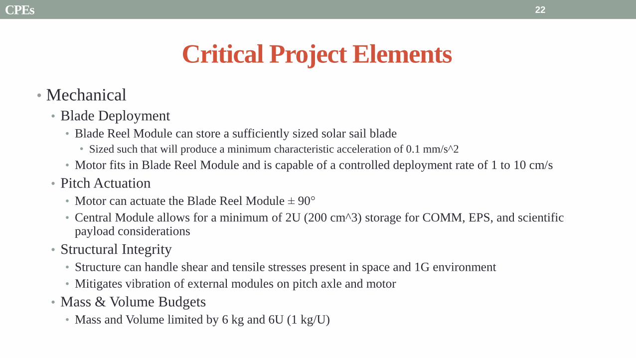
Critical Project Elements
bull Mechanical
bull Blade Deployment
bull Blade Reel Module can store a sufficiently sized solar sail blade
bull Sized such that will produce a minimum characteristic acceleration of 01 mms^2
bull Motor fits in Blade Reel Module and is capable of a controlled deployment rate of 1 to 10 cms
bull Pitch Actuation
bull Motor can actuate the Blade Reel Module plusmn 90deg
bull Central Module allows for a minimum of 2U (200 cm^3) storage for COMM EPS and scientific payload considerations
bull Structural Integrity
bull Structure can handle shear and tensile stresses present in space and 1G environment
bull Mitigates vibration of external modules on pitch axle and motor
bull Mass amp Volume Budgets
bull Mass and Volume limited by 6 kg and 6U (1 kgU)
22 CPEs
Critical Project Elements
bull Electrical bull MicrocontrollerDriverMotor Connection
bull Functional and wiring sufficiently sized to carry necessary current
bull Inter-module service loop connection
bull Thermal Considerations bull Pitch motor and electronics are sufficiently insulated andor heated by electrical coils
bull Electrical heat dissipation does not overheat internal components
bull Power Budget bull Power usage never exceeds 10 W
bull Software bull Algorithms
bull Integrated with electronics bull Language compatible with microcontroller
bull Capable of producing relevant pitch profiles to be used by pitch motor
bull Control initial deployment deployment rate and confirm deployment status
bull Memory Concerns bull Bus has necessary memory storage on board
23 CPEs
Critical Project Elements
bull Space Concerns
bull Launch Vibrations amp Survivability
bull Structural integrity uncompromised due to launch conditions
bull Launch Locks installed for launch vibration mitigation between external Blade Reel Modules and Internal
Central Module
bull Launch Lock design for support of sail blade tip
bull Canisterized Satellite Dispenser (CSD)
bull CubeSat meets specifications for use in dispenser
bull Initial Spin-Up
bull CubeSat induces rotation of its own accord
bull Use of stainless-steel reinforced sail material at blade tip
24 CPEs
Critical Project Elements
bull Manufacturing and Assembly bull Order of Manufacturing
bull Construction from outside-in
bull Wall Construction bull Thickness sufficient for structural needs and use of fasteners
bull Solar Sail bull Attachment to deployment axle in Blade Reel Module
bull Bonding of stainless-steel supports to sail material
bull Pitching Axle bull Connection between pitch motor and external Blade Reel Module
bull Satisfies tensile and shear stress concerns
bull Minimizes vibration between interfaces
bull Bearings
bull CSD Tabs bull Tabs implemented into construction to allow use in satellite dispenser
25 CPEs
Presentation Sections
bull Purpose and Objectives
bull GHOST Design Solution
bull Critical Project Elements
bull Requirement Satisfaction
bull Controlled Deployment Rate
bull Pitching
bull Survive Launch
bull ElectronicSoftware Integration
bull Manufacturing the CubeSat
bull Summary
bull Remaining Risks
bull Verification and Validation of Design
bull Project Planning
26
Initial Spin-Up
bull Problem Initially deploy solar sail straight without aid in centripetal forces
bull Hardened stainless-steel support attached along middle of last 5 m of Sail Membrane and acts as a ldquotape-measurerdquo
bull Properties of ldquotape measurerdquo bull Dim 5m x 2cm x 127μm
bull ρ = 7860 kgm3
bull m = 998 g
bull A maximum torque of 0147 mNmiddotm required by deployment motor
bull Conditions to reach Ω = 1 RPM
bull 120579119901119894119905119888ℎ = 35deg
bull ∆119905119904119901119894119899 119906119901= 184 days
Solar Blade
Steel Spine
CubeSat
Ω = 1 RPM
Rinitial = 5 m
F = 35 μN
27 Controlled Deployment Rate
Centripetal Acceleration
Deployment
Length
(m)
Centripetal
Acceleration
(ms2)
Sail
Mass
(kg)
Centripetal
Force (N)
5 0055 0014 74times10-5
100 11 0080 0088
200 22 015 033
300 33 022 072
400 44 029 127
500 55 036 197
545 58 038 217
28
Rotation Rate Ω = 1 RPM
Orbital Trajectory
Vtip
Ω
Controlled Deployment Rate
Fg
Fc
Fg is negligible
Space to Earth Comparison
29
CubeSat rotating at 1 RPM rarr centripetal acceleration rarr centrifugal tension
Blade is fully deployed rarr maximum centrifugal tension
Simulate same centrifugal tension the blade would experience in space
Total mass of 36 g used in the deployment test
mTotalSpace = 3775 g
F = 217 N
mTotalEarth = 119865
119892 = 2215 g
The holding torque of the motor used must be able to withstand this force
τ = r times F τ = 0011 Nm
Space Application
Motor
CubeSat
rotating at 1
RPM
Blade Tip mass
F
Top View
Tip mass trajectory
mTM = 2070 g
F = mg
Ground Deployment
r
Mounted to Table Side View
Tip
mass
Motor
Blade
Front View
MotorBus
Interface
Controlled Deployment Rate
Deployment Parts List Electronics Part Voltage (V) Current (A) Interface Dimensions (mm) Cost ($)
Sanyo Stepper Motor 35 03 Input 4 (bipolar) 42times42times11 60
DRV8834 Low-Voltage
Stepper Motor Driver
25-108 05phase Output 4
Input 8 (7 IO 1 CCP)
Power 2 (motor and logic)
Ground 2 (motor and logic)
15times20 10
30 Controlled Deployment Rate
Stepper Motor Stepper Motor Driver
Software Prototype
Deployment
Algorithm
bull Written in MATLAB to prove concept of deployment
bull Need to maintain constant deployment rate
Time Step Passes
Find Rotations Made in Time Step
Calculate Length Deployed
Find new Diameter and
Circumference
Calculate new Rotation Rate
Set Initial Diameter
and Circumference
Calculate Rotation
Rate
31 Controlled Deployment Rate
Presentation Sections
bull Purpose and Objectives
bull GHOST Design Solution
bull Critical Project Elements
bull Requirement Satisfaction
bull Controlled Deployment Rate
bull Pitching
bull Survive Launch
bull ElectronicSoftware Integration
bull Manufacturing the CubeSat
bull Summary
bull Remaining Risks
bull Verification and Validation of Design
bull Project Planning
32
The Need for plusmn 90deg Range of Pitch
Blade
Pitch θ
Condition (Profile Description)
0deg Max Thrust (Collective Blade Surface
Normal to Sunlight)
plusmn 35deg Max Torque (Collective) or Max In-Plane
Thrust (1P Cyclic)
plusmn 90deg No Thrust (Collective Blades Edge on to
Solar Wind)
Full 180deg range of motion for blade pitch necessary for spacecraft to have full capabilities of
controlling the thrust vector See Appendix for further information
33 Pitching
Pitching Parts List Electronics
Part Voltage (V) Current (A) Interface Dimensions (mm) Cost ($)
FAULHABER 2036
BLDC Motor
5 02 Input 3 phase
Sensors 3 HALL
Power 1
36times20 (diameter) 230
Atmel ATA6832-DK
Brushless DC Motor
Controller
5 01 Output 3 phase
Input 1 Serial 2 IO
45times45 208
2 Channel IE2-1024
Encoder
5 04 Output 4 I0
Power 1
165times15 (diameter) 225
34
2036 BLDC Motor
Pitching
Servo Controller
bull Bypass LIN input for direct interface with potentiometer
(Serial input use DAC from microcontroller)
35 Pitching
Pitching Software
Pitch Profile Command Sent
Find corresponding
sinusoid equation for pitching
Command servo to turn to angle in
pitching sinusoid
Compare to Encoder Angle
Given a pitch profile the software will
bull Find the corresponding sinusoid command for the
servos
bull Step through those angles over the time period
bull Compare commanded angle to encoder feedback
bull Adjust for accuracy
Pitching 36
Presentation Sections
bull Purpose and Objectives
bull GHOST Design Solution
bull Critical Project Elements
bull Requirement Satisfaction
bull Controlled Deployment Rate
bull Pitching
bull Survive Launch
bull ElectronicSoftware Integration
bull Manufacturing the CubeSat
bull Summary
bull Remaining Risks
bull Verification and Validation of Design
bull Project Planning
37
Canisterized Satellite Dispenser CSD
bull 6U fits into CSD during launch
bull Gives extra clearance on each side bull Allows for locking mechanism outside the 6U
bull Available with Alum 6061
bull Pushed into orbit on ldquoTabrdquo structure bull Additional tabs added below CubeSat base
bull Able to separate tabs for each separate section
38 Survive Launch
Structural Integrity of Pitching Axle and Selection of
Material
bull Aluminum 6061
bull Lightweight (density of 27gcc)
bull Very strong
bull Inexpensive
bull Pitching Axle ndash rod 1 cm in diameter
bull If made of Aluminum 6061
bull Can withstand shear force of 162 kN (~3600 lbs)
bull Does not take into account ability of motor to withstand torque
F (from Solar
Sail)
τ
39 Survive Launch
Pitching Axle
Launch Locks
bull Sierra Nevada SP-5025 pin puller
bull 350 lbf (1500 N) of shear load
bull Powered by a single timed power pulse to one of
the redundant heater circuits
bull SP -5025 greatly exceeds budget so manual
screw and bolt sized appropriately simulate
launch locks in the prototype
40
SP-5025
SP-5025
Deployed
Stowed
Simulated
Launch Locks
Survive Launch
Credit to SNC
Secure Blade Tip Mass
bull C-brackets attached to exterior walls stabilize tip mass vertically and horizontally
bull Cylindrical tip mass fits securely in brackets on both sides
bull Holding torque of stepper motor and tape-measure material holds tip mass in towards rolled blade
bull Within outer limit required by CSD
41
16 cm
075 cm 2 cm
Survive Launch
Presentation Sections
bull Purpose and Objectives
bull GHOST Design Solution
bull Critical Project Elements
bull Requirement Satisfaction
bull Controlled Deployment Rate
bull Pitching
bull Survive Launch
bull ElectronicsSoftware Integration
bull Manufacturing the CubeSat
bull Summary
bull Remaining Risks
bull Verification and Validation of Design
bull Project Planning
42
Service Loop
Power and input wires needed in for stepper
motor in deployment module
bull 4 12A rated wires AWG 21 D = 073 mm
bull Full loop around pitching axle to allow for
plusmn90deg rotational freedom
bull 1 cm diameter hole through each plate
bull Current must run throughout launch to
keep holding torque
bull Need not worry about freezing later in mission
Wires (red) exit opening in wall loops around
pitching axle enters opening in opposite wall
43 ElectronicsSoftware Integration
Electrical Block Diagram
Micro-
controller
35 V Supply
Stepper
Driver
Stepper
Motor
H4
H5
H3
H6
Key IO
CCP
Power
Serial
GND
Sensor
VDD
M0
M1
ENABLE
CONFIG
GND
DIR
STEP
E0
E2
B2
B1
A1
A2
VMOT GND VDD
5 V Supply
GND
Servo
Driver 1
Servo 1 TX RX
P G A B C
5V GND U V W Servo
Driver 2
Servo 2
P G A B C
5V GND C2 C3 C4 U V W
Encoder
J2 J3 J4 J5 J6 J7
VDC G
C0
(Speed Set)
C0
(Speed Set)
RS 232
DAC
A B C
Encoder VDC G A B C
B5 B4
A3
A7
B7
B6
D4
D3
D4 D3
C2 C3 C4
VoutA
VoutB
SCLK CS
DIN
GND
Tin Rout Vin GND
VDD
A4
SLEEP
FAULT H0
E1
44 ElectronicsSoftware Integration
Microcontroller PIC18F87K22
Board Requirements
bull Serial output for communication with computer
and servomotor controller
bullDAC used for servomotor communication
bull I0 ports for stepper driver interface
bull CCP port for stepper driver interface
bull Header pins for the encoder interface
Total
18 IO
1 CCP
1 TXRX
bull Would need more IO and CCP ports for a second
stepper motor driver
bull Unused ports 37 IO and 10 CCPECCP
ElectronicsSoftware Integration
PCB Design
bull 2 Layer Board
bull FR4 material
bull 1 oz Copper traces
bull Estimated Dimension = 5times5 cm
bull (See Appendix for Electrical Schematic)
EasyPIC PRO
v7 Pinout
80 Pin Development
Board
ElectronicsSoftware Integration
Incompatible Industrial Boards
Presentation Sections
bull Purpose and Objectives
bull GHOST Design Solution
bull Critical Project Elements
bull Requirement Satisfaction
bull Controlled Deployment Rate
bull Pitching
bull Survive Launch
bull ElectronicsSoftware Integration
bull Manufacturing the CubeSat
bull Summary
bull Remaining Risks
bull Verification and Validation of Design
bull Project Planning
47
Manufacturing In-House vs Purchasing
48
Part In-House Purchase Details
CubeSat walls Aluminum will be purchased with correct thickness and
manufactured to needed dimensions
Blade and pitching axle Axles can be cut down to needed length
Corner brackets Brackets can be altered to fit needed dimensions
S-brackets and C-brackets Will have to be machined to fit strict dimensions
Tip mass Tip mass can be cut down to needed length
Tape-measure material Purchased from McMaster-Carr
Solar sail blade material Blade material is provided for free by NASA LaRC
Launch Locks Launch locks we will use are a screw and bolt
Launch Tabs for CSD Tabs must meet strict dimensions to fit into CSD from
Planetary Systems Corporation
Hub to attach pitching axle to blade module Will have to be machined to meet needed dimensions
Screwsnutsbolts All can be purchased in various sizes and lengths
Motorsencoders and motor drivers All purchased to meet necessary requirements
Electronics board Will have to be made to accommodate needed electronics
Stabilizers to hold pitching motors Will have to be machined to properly fit around motors
Manufacturing the CubeSat
Assembly Procedure
49 Manufacturing the CubeSat
Bonding Mylar to Spool and Stiff Material
bull Loctite Super Glue Professional
bull Shear strength of 01 Nmm2
bull Cross-Sectional Area = 6575 mm2
bull Shear Stress = 33e-4 Nmm2
bull Blade will retain 4 rolls around axle at
final length
bull Loctite to bond stainless steel stiff
material to Mylar and to spool
F = mg = 217 N
Motor
Blade frac14 of roll glued
50 Manufacturing the CubeSat
Fixing Deployment Motor to S-Bracket
51
bull Deployment stepper motor is attached to S-bracket
bull S-bracket stabilized to back of blade deployment
module and vertical CubeSat walls
bull Motor is capable of being screwed directly to S-bracket
bull S-bracket has thickness of 18 inch
Holes for screws to
stabilize S-bracket
Hole for motor shaft
or press-fit ball
bearing to attach to
blade axle
Holes to screw motor
to S-bracket
Manufacturing the CubeSat
Pitching Axle Interfaces
bull Pitching axle to motor axle
bull Motor axle (smaller) fits into pitching
axle (larger) using set-screws
bull Pitching Axle to Blade Reel
Module
bull Axle fixed by set screws inside a hub
52
Pitching Axle
Hub
Motor Axle
4 Set Screws
Manufacturing the CubeSat
Presentation Sections
bull Purpose and Objectives
bull GHOST design solution
bull Critical Project Elements
bull Requirement Satisfaction
bull Controlled Deployment Rate
bull Pitching
bull Survive Launch
bull ElectronicSoftware Integration
bull Manufacturing the CubeSat
bull Summary
bull Remaining Risks and Mitigations
bull Verification and Validation of Design
bull Schedule and remaining work
53
Requirements Satisfaction
Aspect Requirement GHOST Specification
Mass 1 kgU 288 kg
Volume lt= 12U 6U
Life Span 4 months Greater than 4 months
Space Applicable
While design does not need to be
space worthy it should be applicable
to being used in space
All components are picked for
realistic use in space with minimal
cost parts and increased life span
54 Summary
Requirements Satisfaction
Aspect Requirement GHOST Specification
Characteristic Acceleration ac ge 01 mms2 ac = 03868 mms2
Sail Aspect Ratio AR ge 1001 AR = 38931
Sail Deployment Speed 1 cms le 10cms ~5 cms
Pitching Range Ability to pitch blades plusmn 90deg Ability to pitch blades plusmn 90deg
Pitching Coordination Multiple blade coordination when
pitching
Can pitch both blades at once either to
same angle or opposite angles
55 Summary
Presentation Sections
bullPurpose and Objectives
bullGHOST Design Solution
bullCritical Project Elements
bullRequirement Satisfaction
bullRemaining Risks
bullVerification and Validation of Design
bullProject Planning
56
Design Risks
Severity
Likelihood Marginal Major
Often Pitch angle error root not
following tip
Occasional Power loss COMM loss
Structural survivability
pitching motor failure
Improbable Small tear in Mylar Deploy too fast stowage
and deployment of Mylar
Axle failure
launch fail
space dust
deployment motor failure
57 Remaining Risks
Logistical Risks
Severity
Likelihood Minor Marginal Major
Often Parts delayed due to US
Postal Service
Occasional Structural consultation
unavailable
Ball vibrations test is not
available machine parts
not done on schedule
Government shutdown and
we canrsquot get Mylar or help
from NASA
Improbable No time for pitching test
High Bay in Fleming is
unavailable motors donrsquot
show up
58 Remaining Risks
Financial Risks
Severity
Likelihood Minor Marginal Major
Often Repurchase parts
Occasional Motor breaks Price of shake table
Improbable Hyper inflation
59 Remaining Risks
Presentation Sections
bullPurpose and Objectives
bullGHOST Design Solution
bullCritical Project Elements
bullRequirement Satisfaction
bullRemaining Risks
bullVerification and Validation of Design
bullProject Planning
60
Deployment System
Validate that the blade is deployed at a constant rate of 1-10 cms in a high bay
room
Verify that the motor can deploy at constant rate
Verify with test that the deployment system does not use more than the maximum power available of 10W
Validate that the blade can successfully deploy a blade with tape measure
material at a constant rate along ground
Verify with demonstration that the tape measure material can extend length of
blade
Verification and Validation
Verification and Validation
61
Blade Deployment Testing Information
bull Location Prof Frewrsquos High Bay Lab
bull Scheduled MarchApril with late night access to avoid
scheduling conflicts
bull Measurement Tape measure for distance and video
camera for time
bull Power Delivered 6253A Dual DC Power Supply
delivers 0-20 V and 0-3A
Tape measure
marking
distance up
wall
Kinematic Model
bull Torque from motor drives a constant velocity deployment
120591119898119900119905119900119903 = 120591119903119900119897119897 + 120591119901119906119904ℎ119894119899119892 119879119872 minus 120591119892119903119886119907119894119905119910 119879119872
120591119903119900119897119897 =119889119868119903119900119897119897
119889119905120596119903119900119897119897 + 119868119903119900119897119897
119889120596119903119900119897119897
119889119905
120591119901119906119904ℎ119894119899119892 119879119872 =119889119898119890119909119905
119889119905119903119903119900119897119897119907 + 119898119890119909119905
119889119903119903119900119897119897
119889119905119907
120591119892119903119886119907119894119905119910 119879119872 = 119898119890119909119905119903119903119900119897119897119892 bull 120649119945119952119949119941119946119951119944 = 120782 120782120790120787 N∙m 120649119950119952119941119942119949119950119938119961 = 120782 120782120782120789 N∙m
Power Supply
Verification and Validation
CubeSat Wire
62
Pitching System
Validate that the blade reel modules experience coordinated pitching
Verify that one blade reel module experiences periodic
motion
Verify that the blade reel module rotates to 0deg upon
initialization
Verify that the blade pitches to a given command
angle
Verify that the motorencoder system does not exceed power
available
Verification and Validation
Verification and Validation
63
Verify Pitching Angle Experiment Equipment and Specs
bull Use R60D RVIT (Rotary Variable Inductance Transducer) sensor to measure angles attaches to pin (red) in line with pitching axis bull Measures ranges of plusmn60deg rotation
bull Input Voltage = plusmn15 V
bull Output Voltage = plusmn75 V
bull Resolution = 0125 Vdeg
bull 119891119898119886119909 = 20 Hz
bull Use AD524 Precision Amplifier Instrumentation for signal conditioning bull Input Voltage plusmn10 V
bull Output Voltage plusmn10V
bull Requires Supply Voltage plusmn15
bull Use NI 9201 bull Input Voltage plusmn10 V
bull Has a USB output that can connect to a computer where vi program records
Experiment Set-Up
R60D RVIT
AD524
NI 9201 PC via USB
Verification and Validation 64
Verify Periodic Motion Experiment
bull Using the R60D RVIT set-up to measure deflection angles
bull With data of the angle deflection 120579 angular velocity 120596 and angular acceleration 120572 can be measured bull Motor restriction 120591119898119886119909 = 032 Nmiddotm
bull Model restriction 120596119898119886119909 = Ω2 if Ω = 2rpm 120596119898119886119909 = 02094 rads
Validation Model
bull R60D RVIT measures plusmn60deg deflection angles bull Critical condition blade reel module pitches plusmn90deg Ω=2rpm
bull 120572119888 = 00172 rads2 and 120596119898 = 0164 rads thus 120591119898 = 0083 mNmiddotm (119868119898119900119889 = 00048 kgmiddotm2)
120579 119905 120596 119905 120572 119905
Verification and Validation 65
Verification and Validation
Structural System
Validate that the final design can survive launch by using a shake
table
Verify the structural integrity by demonstrating that all stationary parts are
static
Verification and Validation 66
Trade Study FEM vs Vibration Table
Cost Time Experience
Similar to
Actual
Launch
Guaranteed Can
Do Total
FEM 4 1 1 3 4 215
Vibration
Table 2 3 4 4 2 32
Weight () 5 30 25 20 20 100
67 Verification and Validation
See Appendix for Full Trade Study
Validate Structural Stability
bull Will use a shaker table from Ball Aerospace
bull Cost = $250hr
bull Schedule Time to be determined in April
bull Specifications Peak vibration occurs with 34g at
frequency of 16 Hz (Saturn V)
bull Will be verified by examining the structural integrity
of the manufacturing
Verification and Validation 68
CubeSat
Shake Table
Presentation Sections
bullPurpose and Objectives
bullGHOST Design Solution
bullCritical Project Elements
bullRequirement Satisfaction
bullRemaining Risks
bullVerification and Validation of Design
bullProject Planning
69
Organizational Chart
Mark
Dolezal
Emily
Proano
Lauren
Persons
Casey
Myers
Nicholas
Busbey
Taylor
Smith
Karynna
Tuan
Megan
Scheele
Project
Manager
Software
Lead
Electrical
Lead
Systems Test and
Safety
Manufacturing
Lead Mechanics
Lead
CFO and
Materials
Lead
Organizing
team
meetings
Supporting
other leads
Non CPE
Tasks
Deployment
Control
Pitching
Control Motors and
Electronics
Power
Integrate
all system Perform
and Plan
tests
Manufacture
all in-house
parts
SolidWorks
Keep track
of financial
spending
Right
materials
are being
utilized
CubeSat
Assembly
Specific
System
Requirements
70 Project Planning
GHOST
Materials Mechanical Electrical Software Documents
Shake Table
Vibration
Analysis
Mechanical
Layout
Power Budget Pitch Control
Algorithm
Deployment
Rate Control
Algorithm SolidWorks
Model
Electrical
Wiring Layout
Thermodynamic
Analysis of
Electronic System
Mass Budget
Prototype of
CubeSat Bus
Motor
Subsystem
CDR
FFR
Spring
Schedule
Financial
Budget
Work Breakdown Structure (WBS)
Mylar from
NASA
Spin Up
Algorithm
Emergency
StopRestart System
71 Project Planning
PCB Design
Spring
Documents
113 120 127 203 210 217 224 303 310 317 324 331 407 414 421 428
MSR TRR SFR PFR
Time (date)
Purchase
motorsdrivers
Preliminary code
Electronic
integration
Test code
Electronicscode
interface
Purchase
raw materials
Manufacture frame
Assemble bus
Manufacture
remaining parts
Integrate system
Deployment test
Pitching test
Vibration test
Ta
sks
72
GHOST Spring Schedule
Project Planning
Planned Uncertainty
Key
Test Plan Test Scheduled Facility Specialized Equipment
Verify Pitch Angle 317 ITLL R60D RVIT NI 9201 AD524 Oscilloscope bench
power source
Zero Pitch Angle 317 ITLL R60D RVIT NI 9201 AD524 Oscilloscope bench
power source
Measure power used in
pitchdeployment 317 ITLL Ammeter voltmeter bench power source
Verify constant deployment 324 ITLL Firewire camera bench power source
ASEN2003BallTrackervi
Verify periodic motion 324 ITLL R60D RVIT NI 9201 AD524 Oscilloscope bench
power source
Validate tape measure ground
deployment 331 ITLL
Bench power source tape measure stop watch rollers
for tip mass
Validate coordinated pitching 331 ITLL R60D RVIT NI 9201 AD524 oscilloscope bench
power source
Validate 1g blade deployment 331-414 Prof Frew
high bay
Portable 6253A Dual DC Power Supply ladder tape
measure video camera
Validate launch ready 414 Ball Aero Shake Table
Project Planning 73
Cost Table ndash Structural Components
Part Price per
part NeededVolume Needed Total Price Supplier
Aluminum 6061 Sheet
(18rdquo thick) $ 8976 2ft times 2ft times 18 in $ 8976 The Metals Depot
Aluminum 6061 rod
(14 in diameter) $280 2 ft $280 The Metals Depot
Aluminum6061 rod
(716 in diameter) $494 2 ft $494 The Metals Depot
Steel Corner Brackets
(34rdquo times 12rdquo)
$197 4
braces 16 $788 Home Depot
Hardened 302 Stainless
Steel $3300 2 cm times 5 m times 127 microm $3300 McMaster-Carr
Total $11834
74 Project Planning
Cost Table ndash Electrical Components
Part Price per
part Needed Total Price Supplier
Sanyo Stepper Motor $ 5995 2 $11990 Pololu Electronics and Robotics
DRV8834 Low-Voltage Stepper
Motor Driver $995 2 $1990 Pololu Electronics and Robotics
FAULHABER 2036 BLDC
Servo Motor $23000 2 $46000 MicroMo Micro Motion Solutions
Atmel ATA6832-DK Brushless
DC Motor Controller $20800 2 $41600 Atmel
Encoder AU-ZSD1000A $22500 2 $45000 MicroMo Micro Motion Solutions
PIC18F87K22 Microcontroller $500 1 $500 Microchip
AD-524 Signal Converter $1767 1 $1767 Agilent
Total $148847
75 Project Planning
Questions
76
References
bull wwwloctiteproductscom
bull Vallado D A Fundamentals of Astrodynamics and Applications
bull Guerrant D Lawrence D Heaton A Earth Escape Capabilities of the Heliogyro Sail AIAA Paper
bull wwwspaceflightnowcom
bull Guerrant D HGVizGuim MATLAB Program
bull httpwwwmicromocombrushless-dc-motorsaspx
bull httpwwwfaulhabercomservletcomitmrwawservletAnzeigefremdaufruf=jaampkdid=40929ampsprachid=1amphtdigurl=n169933i95222html
bull httpwwwpololucom
bull httpasmmatwebcomsearchSpecificMaterialaspbassnum=MA6061t6
bull httpwwwruagcomthermalSpace_Thermal_HardwareMulti_Layer_Insulation
bull Helgesen Bryan Sierra Nevada Corporation
77
GyroSail Launch Configuration and Deployment Sequence
78
1 Launch configuration (6U) 2 Blade reel modules pitch to zero Fits within a 6U or 12U dispenser
3 PV arrays deploy
Other array configurations are possible
williamkwilkienasagov NASA PREDECISIONAL - FOR DISCUSSION PURPOSES ONLY
78 Appendix
GyroSail Primary Bus Systems Based on modified JPLU MichUCLACal PolyUT INSPIRE bus
williamkwilkienasagov
05U cold gas thruster ACS for detumbling
and initial spin-up
(httpwwwaustinsatnet)
05U EPS battery CampDH UHF backup
comms (U Mich) 05U DSN-compatible X-band
communications (JPL)
05U COTS star trackerimager ADC (BCT) sail
module processor (CU)
Klesh A et al 2013 ldquoINSPIRE Interplanetary NanoSpacecraft Pathfinder In Relevant Environmentrdquo Proceedings of the AIAAUSU Conference on Small Satellites Around the Corner SSC13-
XI-8 httpdigitalcommonsusuedusmallsat2013all2013127
NASA PREDECISIONAL - FOR DISCUSSION PURPOSES ONLY
79 Appendix
COMM Subsystem
bull 18 m Ka-band antennas at White
Sands New Mexico
bull Goddard Space Flight Center
Greebelt Maryland USA
supplied the Mulemba Space
Center in Angola
80 Appendix
Orion Crew
Module
6U Canisterized Satellite
Dispenser (CSD) ESPA Ring
Spacecraft
Adapter
Interim Cryogenic Propulsion
Stage (ICPS)
Secondary Payload Attachment to SLS
The SLS design is currently going through CDR An ESPA
ring is not currently in place but is mentioned in the SLS
CONOPS in order to accommodate secondary payloads
81 Appendix
Max Thrust Condition Collective 90deg pitch profile
Max thrust normal to orbital plane
(Halo orbits orbital plane rotation ie
inclination change)
82
Credit to Dan Guerrant
Appendix
Max Thrust Condition
F vs β M vs β
83
Credit to Dan Guerrant
Appendix
No Thrust Condition Collective 0deg pitch profile
Zero thrust
84
Credit to Dan Guerrant
Appendix
No Thrust Condition
F vs β M vs β
85
Credit to Dan Guerrant
Appendix
Max Torque Condition Collective 35deg pitch profile
Max torque used for spinning up sc
(opposite orientation for despinning)
86
Credit to Dan Guerrant
Appendix
Max Torque Condition
F vs β M vs β
87
Credit to Dan Guerrant
Appendix
Max In-Plane Thrust Condition Cyclic 35deg pitch profile
Max thrust in in-plane (d2) direction for orbit raising
88
Credit to Dan Guerrant
Appendix
Max In-Plane Thrust Condition
F vs β M vs β
89
Credit to Dan Guerrant
Appendix
Orbit Raising
F
90 Appendix
Thermal Space Concerns
bull Material Concerns
bull Aluminum 6061 -196 degC to 160deg C
bull Electronics Concerns
bull Typical Operating Temperature -55 to 80 degC
bull Countermeasures
bull Multi-layer Insulation AAErotherm S10-190
bull (0005 ndash 0035 Wm2K)
bull Battery operated heaters for pre-sail deployment
Multi-layer Insulation
Layer 1 1 x Outer layer
Layer 2 8 x 03 mil VDAPolyimideVDA perf
8 x Woven Polyester netting
Layer 3 1 x Outer layer
Layer 4 1 x Woven Polyester netting
91 Appendix
Rolled Up Blade Reel Calculation Optimal Sail Length 545 m ndash Sail chord of 14 cm
Max Diameter of Spool 598 cm
Diameter of Axle 05 cm
Length of Stiff Material 5 m
Dimension of Stiff Material 5 m times 2 cm times 127 microm
92 Appendix
Torque calculation
bull Note current calculated via T=kI (where T is torque I is amp k is the torque
constant specific to the motor)
T = kI
(k = 005 NmA)
93 Appendix
Servo Controller
94 Appendix
Encoder Dimensions and Interface
bull FAULHABER IE2-1024
95 Appendix
Stepper Motor Torque
96 Appendix
Motor Phases (Stepper)
97 Appendix
98 Appendix
99 Appendix
100 Appendix
101 Appendix
Microcontroller
102 Appendix
ATA6832 Phase Output Chip
103 Appendix
ATA6624 Bypassed Chip
bull Bypassed chip
on servo controller
104 Appendix
Power Budget
105 Appendix
Wire Gauge
bull Stepper Motor 26AWG (04 mm diameter)
bull Servomotor 24 AWG (051 mm diameter)
bull Encoder 24 AWG
Voltage Drop () AWG Max Gauge
001 5
01 15
1 25
5 32
NOTE Voltage drop calculated at 1A and 40 cm of wire
106
24 AWG Wire
Appendix
Trade Study ndash FEM vs Vibration Table
Factor 4 3 2 1
Cost No money 0 gt C gt $100 $100 gt C gt $300 $300 lt C
Time 0 min lt T lt 30 min 30 min lt T lt 2 hrs 2 hrs lt T lt 1 day 1day lt T
Experience Everyone has
experience
A couple people
know how to
1 person has
experience
No one has
experience
Similar To Actual
Launch Simulate real launch
Doesnrsquot have all
variables experienced
Has only a couple
similarities
No similarities to
launch
Guaranteed Can Do
Donrsquot need any
outside equipment or
help
Need outside
equipment but
guaranteed use
Need outside
equipment but own
work at higher
priority
Need outside
equipment but canrsquot
use
Scoring
107 Appendix
Weighting
Weight () Category Reasoning
5 Cost Have a lot of extra $ in the budget
30 Time Have a strict schedule but not a main focus of the
project
25 Experience If no one has experience it will take a lot of time
20 Similar to Actual Launch Needs to be like actual launch
20 Guaranteed Can Do Needs to be able to accomplish but not the most
important focus
108 Appendix
Finite Element Method (FEM)
Objectives Description ProCon
Cost No money because one of us
would do it Pro
Time A lot of time to learn and then
perform FEM Con
Experience No one in group has FEM
experience Con
Similar to Actual Launch Very similar to actual launch Pro
Guaranteed Can Do All we need is paper pen and
theory to do Pro
109 Appendix
Vibration Table
Objective Description ProCons
Cost $250hr Con
Time A hour on the table should simulate
launch Pro
Experience Donrsquot need experience to run
vibration table Pro
Similar to Actual Launch Actually putting our system through
vibration stress Pro
Guaranteed Can Do No guarantee but most likely can Con
110 Appendix
SpinUp State
1 Check value of SpinUp to see if satellite is already spun up
bull Continue if satellite is not already spun-up
2 Deploy the tape stiffened length of the blade
3 Pitch to the spin up angle
4 Wait until characteristic angular velocity is reached
5 Pitch to pre-deployment position
6 Save SpinUp as completed
Appendix 111
Deployment State
1 Check if satellite has been spun up yet
bull Continue if it has
2 Check if blades are already deployed
bull Continue if they havenrsquot
3 Run deploy algorithm until blades are fully deployed
4 Save value saying blades have been deployed
Appendix 112
Pitching State
1 Check if satellite has been spun up
bull Continue if satellite has been spun up
2 Check if blades have been deployed
bull Continue if blades have been deployed
3 Look at commanded pitch profile
4 Find correlated sinusoid command
5 Command servo to pitch angle for the time in the orbit
6 Continue until given a new pitch command
Appendix 113
Emergency Stop
1 Save which state was interrupted
2 Save last position in interrupted
state
3 Wait until Restart command is
received
1 Check two previous states to see
what is being restarted
2 Look at saved last position in
state being restarted
3 Adapt the algorithm of the state
to continue where left off
Restart
Appendix 114
Comparison with Previous Heliogyro Concepts MIT (1989) NASA (2011) GHOST
Total sail craft mass (kg) 18 84
288 (6)
Characteristic acceleration ac
(mms2) 06 10 03868 (01854)
Sail reflective area (m2) 1200 960 1526
Non-sail mass (kg) 5 5 --
Number of sail blades 8 6 2
Blade chord (m) 15 08 014
Blade length (m) 100 200 545
Rotational period (minutes) 3 3 1
Blade root stress (Pa) 8650 34000 --
Blade root allowable stress (Pa) 55 M 55 M --
Blade root tension load (N) 01 007 --
115 Appendix
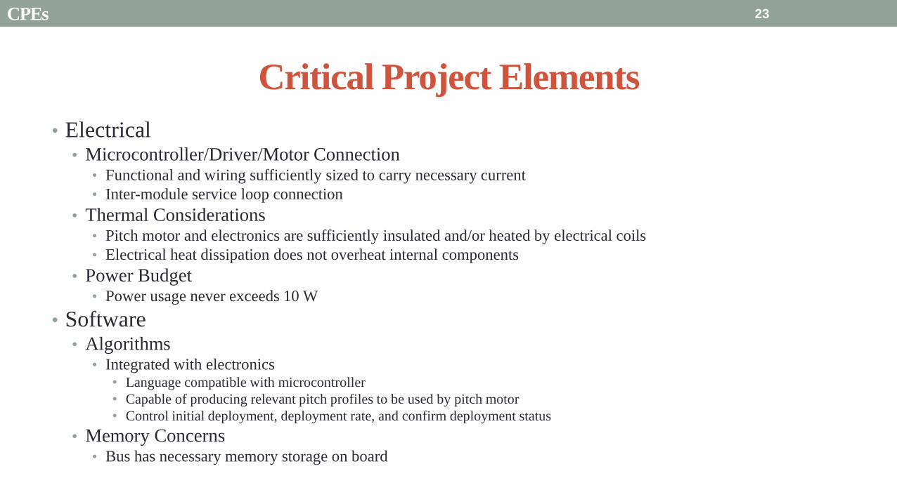
Critical Project Elements
bull Electrical bull MicrocontrollerDriverMotor Connection
bull Functional and wiring sufficiently sized to carry necessary current
bull Inter-module service loop connection
bull Thermal Considerations bull Pitch motor and electronics are sufficiently insulated andor heated by electrical coils
bull Electrical heat dissipation does not overheat internal components
bull Power Budget bull Power usage never exceeds 10 W
bull Software bull Algorithms
bull Integrated with electronics bull Language compatible with microcontroller
bull Capable of producing relevant pitch profiles to be used by pitch motor
bull Control initial deployment deployment rate and confirm deployment status
bull Memory Concerns bull Bus has necessary memory storage on board
23 CPEs
Critical Project Elements
bull Space Concerns
bull Launch Vibrations amp Survivability
bull Structural integrity uncompromised due to launch conditions
bull Launch Locks installed for launch vibration mitigation between external Blade Reel Modules and Internal
Central Module
bull Launch Lock design for support of sail blade tip
bull Canisterized Satellite Dispenser (CSD)
bull CubeSat meets specifications for use in dispenser
bull Initial Spin-Up
bull CubeSat induces rotation of its own accord
bull Use of stainless-steel reinforced sail material at blade tip
24 CPEs
Critical Project Elements
bull Manufacturing and Assembly bull Order of Manufacturing
bull Construction from outside-in
bull Wall Construction bull Thickness sufficient for structural needs and use of fasteners
bull Solar Sail bull Attachment to deployment axle in Blade Reel Module
bull Bonding of stainless-steel supports to sail material
bull Pitching Axle bull Connection between pitch motor and external Blade Reel Module
bull Satisfies tensile and shear stress concerns
bull Minimizes vibration between interfaces
bull Bearings
bull CSD Tabs bull Tabs implemented into construction to allow use in satellite dispenser
25 CPEs
Presentation Sections
bull Purpose and Objectives
bull GHOST Design Solution
bull Critical Project Elements
bull Requirement Satisfaction
bull Controlled Deployment Rate
bull Pitching
bull Survive Launch
bull ElectronicSoftware Integration
bull Manufacturing the CubeSat
bull Summary
bull Remaining Risks
bull Verification and Validation of Design
bull Project Planning
26
Initial Spin-Up
bull Problem Initially deploy solar sail straight without aid in centripetal forces
bull Hardened stainless-steel support attached along middle of last 5 m of Sail Membrane and acts as a ldquotape-measurerdquo
bull Properties of ldquotape measurerdquo bull Dim 5m x 2cm x 127μm
bull ρ = 7860 kgm3
bull m = 998 g
bull A maximum torque of 0147 mNmiddotm required by deployment motor
bull Conditions to reach Ω = 1 RPM
bull 120579119901119894119905119888ℎ = 35deg
bull ∆119905119904119901119894119899 119906119901= 184 days
Solar Blade
Steel Spine
CubeSat
Ω = 1 RPM
Rinitial = 5 m
F = 35 μN
27 Controlled Deployment Rate
Centripetal Acceleration
Deployment
Length
(m)
Centripetal
Acceleration
(ms2)
Sail
Mass
(kg)
Centripetal
Force (N)
5 0055 0014 74times10-5
100 11 0080 0088
200 22 015 033
300 33 022 072
400 44 029 127
500 55 036 197
545 58 038 217
28
Rotation Rate Ω = 1 RPM
Orbital Trajectory
Vtip
Ω
Controlled Deployment Rate
Fg
Fc
Fg is negligible
Space to Earth Comparison
29
CubeSat rotating at 1 RPM rarr centripetal acceleration rarr centrifugal tension
Blade is fully deployed rarr maximum centrifugal tension
Simulate same centrifugal tension the blade would experience in space
Total mass of 36 g used in the deployment test
mTotalSpace = 3775 g
F = 217 N
mTotalEarth = 119865
119892 = 2215 g
The holding torque of the motor used must be able to withstand this force
τ = r times F τ = 0011 Nm
Space Application
Motor
CubeSat
rotating at 1
RPM
Blade Tip mass
F
Top View
Tip mass trajectory
mTM = 2070 g
F = mg
Ground Deployment
r
Mounted to Table Side View
Tip
mass
Motor
Blade
Front View
MotorBus
Interface
Controlled Deployment Rate
Deployment Parts List Electronics Part Voltage (V) Current (A) Interface Dimensions (mm) Cost ($)
Sanyo Stepper Motor 35 03 Input 4 (bipolar) 42times42times11 60
DRV8834 Low-Voltage
Stepper Motor Driver
25-108 05phase Output 4
Input 8 (7 IO 1 CCP)
Power 2 (motor and logic)
Ground 2 (motor and logic)
15times20 10
30 Controlled Deployment Rate
Stepper Motor Stepper Motor Driver
Software Prototype
Deployment
Algorithm
bull Written in MATLAB to prove concept of deployment
bull Need to maintain constant deployment rate
Time Step Passes
Find Rotations Made in Time Step
Calculate Length Deployed
Find new Diameter and
Circumference
Calculate new Rotation Rate
Set Initial Diameter
and Circumference
Calculate Rotation
Rate
31 Controlled Deployment Rate
Presentation Sections
bull Purpose and Objectives
bull GHOST Design Solution
bull Critical Project Elements
bull Requirement Satisfaction
bull Controlled Deployment Rate
bull Pitching
bull Survive Launch
bull ElectronicSoftware Integration
bull Manufacturing the CubeSat
bull Summary
bull Remaining Risks
bull Verification and Validation of Design
bull Project Planning
32
The Need for plusmn 90deg Range of Pitch
Blade
Pitch θ
Condition (Profile Description)
0deg Max Thrust (Collective Blade Surface
Normal to Sunlight)
plusmn 35deg Max Torque (Collective) or Max In-Plane
Thrust (1P Cyclic)
plusmn 90deg No Thrust (Collective Blades Edge on to
Solar Wind)
Full 180deg range of motion for blade pitch necessary for spacecraft to have full capabilities of
controlling the thrust vector See Appendix for further information
33 Pitching
Pitching Parts List Electronics
Part Voltage (V) Current (A) Interface Dimensions (mm) Cost ($)
FAULHABER 2036
BLDC Motor
5 02 Input 3 phase
Sensors 3 HALL
Power 1
36times20 (diameter) 230
Atmel ATA6832-DK
Brushless DC Motor
Controller
5 01 Output 3 phase
Input 1 Serial 2 IO
45times45 208
2 Channel IE2-1024
Encoder
5 04 Output 4 I0
Power 1
165times15 (diameter) 225
34
2036 BLDC Motor
Pitching
Servo Controller
bull Bypass LIN input for direct interface with potentiometer
(Serial input use DAC from microcontroller)
35 Pitching
Pitching Software
Pitch Profile Command Sent
Find corresponding
sinusoid equation for pitching
Command servo to turn to angle in
pitching sinusoid
Compare to Encoder Angle
Given a pitch profile the software will
bull Find the corresponding sinusoid command for the
servos
bull Step through those angles over the time period
bull Compare commanded angle to encoder feedback
bull Adjust for accuracy
Pitching 36
Presentation Sections
bull Purpose and Objectives
bull GHOST Design Solution
bull Critical Project Elements
bull Requirement Satisfaction
bull Controlled Deployment Rate
bull Pitching
bull Survive Launch
bull ElectronicSoftware Integration
bull Manufacturing the CubeSat
bull Summary
bull Remaining Risks
bull Verification and Validation of Design
bull Project Planning
37
Canisterized Satellite Dispenser CSD
bull 6U fits into CSD during launch
bull Gives extra clearance on each side bull Allows for locking mechanism outside the 6U
bull Available with Alum 6061
bull Pushed into orbit on ldquoTabrdquo structure bull Additional tabs added below CubeSat base
bull Able to separate tabs for each separate section
38 Survive Launch
Structural Integrity of Pitching Axle and Selection of
Material
bull Aluminum 6061
bull Lightweight (density of 27gcc)
bull Very strong
bull Inexpensive
bull Pitching Axle ndash rod 1 cm in diameter
bull If made of Aluminum 6061
bull Can withstand shear force of 162 kN (~3600 lbs)
bull Does not take into account ability of motor to withstand torque
F (from Solar
Sail)
τ
39 Survive Launch
Pitching Axle
Launch Locks
bull Sierra Nevada SP-5025 pin puller
bull 350 lbf (1500 N) of shear load
bull Powered by a single timed power pulse to one of
the redundant heater circuits
bull SP -5025 greatly exceeds budget so manual
screw and bolt sized appropriately simulate
launch locks in the prototype
40
SP-5025
SP-5025
Deployed
Stowed
Simulated
Launch Locks
Survive Launch
Credit to SNC
Secure Blade Tip Mass
bull C-brackets attached to exterior walls stabilize tip mass vertically and horizontally
bull Cylindrical tip mass fits securely in brackets on both sides
bull Holding torque of stepper motor and tape-measure material holds tip mass in towards rolled blade
bull Within outer limit required by CSD
41
16 cm
075 cm 2 cm
Survive Launch
Presentation Sections
bull Purpose and Objectives
bull GHOST Design Solution
bull Critical Project Elements
bull Requirement Satisfaction
bull Controlled Deployment Rate
bull Pitching
bull Survive Launch
bull ElectronicsSoftware Integration
bull Manufacturing the CubeSat
bull Summary
bull Remaining Risks
bull Verification and Validation of Design
bull Project Planning
42
Service Loop
Power and input wires needed in for stepper
motor in deployment module
bull 4 12A rated wires AWG 21 D = 073 mm
bull Full loop around pitching axle to allow for
plusmn90deg rotational freedom
bull 1 cm diameter hole through each plate
bull Current must run throughout launch to
keep holding torque
bull Need not worry about freezing later in mission
Wires (red) exit opening in wall loops around
pitching axle enters opening in opposite wall
43 ElectronicsSoftware Integration
Electrical Block Diagram
Micro-
controller
35 V Supply
Stepper
Driver
Stepper
Motor
H4
H5
H3
H6
Key IO
CCP
Power
Serial
GND
Sensor
VDD
M0
M1
ENABLE
CONFIG
GND
DIR
STEP
E0
E2
B2
B1
A1
A2
VMOT GND VDD
5 V Supply
GND
Servo
Driver 1
Servo 1 TX RX
P G A B C
5V GND U V W Servo
Driver 2
Servo 2
P G A B C
5V GND C2 C3 C4 U V W
Encoder
J2 J3 J4 J5 J6 J7
VDC G
C0
(Speed Set)
C0
(Speed Set)
RS 232
DAC
A B C
Encoder VDC G A B C
B5 B4
A3
A7
B7
B6
D4
D3
D4 D3
C2 C3 C4
VoutA
VoutB
SCLK CS
DIN
GND
Tin Rout Vin GND
VDD
A4
SLEEP
FAULT H0
E1
44 ElectronicsSoftware Integration
Microcontroller PIC18F87K22
Board Requirements
bull Serial output for communication with computer
and servomotor controller
bullDAC used for servomotor communication
bull I0 ports for stepper driver interface
bull CCP port for stepper driver interface
bull Header pins for the encoder interface
Total
18 IO
1 CCP
1 TXRX
bull Would need more IO and CCP ports for a second
stepper motor driver
bull Unused ports 37 IO and 10 CCPECCP
ElectronicsSoftware Integration
PCB Design
bull 2 Layer Board
bull FR4 material
bull 1 oz Copper traces
bull Estimated Dimension = 5times5 cm
bull (See Appendix for Electrical Schematic)
EasyPIC PRO
v7 Pinout
80 Pin Development
Board
ElectronicsSoftware Integration
Incompatible Industrial Boards
Presentation Sections
bull Purpose and Objectives
bull GHOST Design Solution
bull Critical Project Elements
bull Requirement Satisfaction
bull Controlled Deployment Rate
bull Pitching
bull Survive Launch
bull ElectronicsSoftware Integration
bull Manufacturing the CubeSat
bull Summary
bull Remaining Risks
bull Verification and Validation of Design
bull Project Planning
47
Manufacturing In-House vs Purchasing
48
Part In-House Purchase Details
CubeSat walls Aluminum will be purchased with correct thickness and
manufactured to needed dimensions
Blade and pitching axle Axles can be cut down to needed length
Corner brackets Brackets can be altered to fit needed dimensions
S-brackets and C-brackets Will have to be machined to fit strict dimensions
Tip mass Tip mass can be cut down to needed length
Tape-measure material Purchased from McMaster-Carr
Solar sail blade material Blade material is provided for free by NASA LaRC
Launch Locks Launch locks we will use are a screw and bolt
Launch Tabs for CSD Tabs must meet strict dimensions to fit into CSD from
Planetary Systems Corporation
Hub to attach pitching axle to blade module Will have to be machined to meet needed dimensions
Screwsnutsbolts All can be purchased in various sizes and lengths
Motorsencoders and motor drivers All purchased to meet necessary requirements
Electronics board Will have to be made to accommodate needed electronics
Stabilizers to hold pitching motors Will have to be machined to properly fit around motors
Manufacturing the CubeSat
Assembly Procedure
49 Manufacturing the CubeSat
Bonding Mylar to Spool and Stiff Material
bull Loctite Super Glue Professional
bull Shear strength of 01 Nmm2
bull Cross-Sectional Area = 6575 mm2
bull Shear Stress = 33e-4 Nmm2
bull Blade will retain 4 rolls around axle at
final length
bull Loctite to bond stainless steel stiff
material to Mylar and to spool
F = mg = 217 N
Motor
Blade frac14 of roll glued
50 Manufacturing the CubeSat
Fixing Deployment Motor to S-Bracket
51
bull Deployment stepper motor is attached to S-bracket
bull S-bracket stabilized to back of blade deployment
module and vertical CubeSat walls
bull Motor is capable of being screwed directly to S-bracket
bull S-bracket has thickness of 18 inch
Holes for screws to
stabilize S-bracket
Hole for motor shaft
or press-fit ball
bearing to attach to
blade axle
Holes to screw motor
to S-bracket
Manufacturing the CubeSat
Pitching Axle Interfaces
bull Pitching axle to motor axle
bull Motor axle (smaller) fits into pitching
axle (larger) using set-screws
bull Pitching Axle to Blade Reel
Module
bull Axle fixed by set screws inside a hub
52
Pitching Axle
Hub
Motor Axle
4 Set Screws
Manufacturing the CubeSat
Presentation Sections
bull Purpose and Objectives
bull GHOST design solution
bull Critical Project Elements
bull Requirement Satisfaction
bull Controlled Deployment Rate
bull Pitching
bull Survive Launch
bull ElectronicSoftware Integration
bull Manufacturing the CubeSat
bull Summary
bull Remaining Risks and Mitigations
bull Verification and Validation of Design
bull Schedule and remaining work
53
Requirements Satisfaction
Aspect Requirement GHOST Specification
Mass 1 kgU 288 kg
Volume lt= 12U 6U
Life Span 4 months Greater than 4 months
Space Applicable
While design does not need to be
space worthy it should be applicable
to being used in space
All components are picked for
realistic use in space with minimal
cost parts and increased life span
54 Summary
Requirements Satisfaction
Aspect Requirement GHOST Specification
Characteristic Acceleration ac ge 01 mms2 ac = 03868 mms2
Sail Aspect Ratio AR ge 1001 AR = 38931
Sail Deployment Speed 1 cms le 10cms ~5 cms
Pitching Range Ability to pitch blades plusmn 90deg Ability to pitch blades plusmn 90deg
Pitching Coordination Multiple blade coordination when
pitching
Can pitch both blades at once either to
same angle or opposite angles
55 Summary
Presentation Sections
bullPurpose and Objectives
bullGHOST Design Solution
bullCritical Project Elements
bullRequirement Satisfaction
bullRemaining Risks
bullVerification and Validation of Design
bullProject Planning
56
Design Risks
Severity
Likelihood Marginal Major
Often Pitch angle error root not
following tip
Occasional Power loss COMM loss
Structural survivability
pitching motor failure
Improbable Small tear in Mylar Deploy too fast stowage
and deployment of Mylar
Axle failure
launch fail
space dust
deployment motor failure
57 Remaining Risks
Logistical Risks
Severity
Likelihood Minor Marginal Major
Often Parts delayed due to US
Postal Service
Occasional Structural consultation
unavailable
Ball vibrations test is not
available machine parts
not done on schedule
Government shutdown and
we canrsquot get Mylar or help
from NASA
Improbable No time for pitching test
High Bay in Fleming is
unavailable motors donrsquot
show up
58 Remaining Risks
Financial Risks
Severity
Likelihood Minor Marginal Major
Often Repurchase parts
Occasional Motor breaks Price of shake table
Improbable Hyper inflation
59 Remaining Risks
Presentation Sections
bullPurpose and Objectives
bullGHOST Design Solution
bullCritical Project Elements
bullRequirement Satisfaction
bullRemaining Risks
bullVerification and Validation of Design
bullProject Planning
60
Deployment System
Validate that the blade is deployed at a constant rate of 1-10 cms in a high bay
room
Verify that the motor can deploy at constant rate
Verify with test that the deployment system does not use more than the maximum power available of 10W
Validate that the blade can successfully deploy a blade with tape measure
material at a constant rate along ground
Verify with demonstration that the tape measure material can extend length of
blade
Verification and Validation
Verification and Validation
61
Blade Deployment Testing Information
bull Location Prof Frewrsquos High Bay Lab
bull Scheduled MarchApril with late night access to avoid
scheduling conflicts
bull Measurement Tape measure for distance and video
camera for time
bull Power Delivered 6253A Dual DC Power Supply
delivers 0-20 V and 0-3A
Tape measure
marking
distance up
wall
Kinematic Model
bull Torque from motor drives a constant velocity deployment
120591119898119900119905119900119903 = 120591119903119900119897119897 + 120591119901119906119904ℎ119894119899119892 119879119872 minus 120591119892119903119886119907119894119905119910 119879119872
120591119903119900119897119897 =119889119868119903119900119897119897
119889119905120596119903119900119897119897 + 119868119903119900119897119897
119889120596119903119900119897119897
119889119905
120591119901119906119904ℎ119894119899119892 119879119872 =119889119898119890119909119905
119889119905119903119903119900119897119897119907 + 119898119890119909119905
119889119903119903119900119897119897
119889119905119907
120591119892119903119886119907119894119905119910 119879119872 = 119898119890119909119905119903119903119900119897119897119892 bull 120649119945119952119949119941119946119951119944 = 120782 120782120790120787 N∙m 120649119950119952119941119942119949119950119938119961 = 120782 120782120782120789 N∙m
Power Supply
Verification and Validation
CubeSat Wire
62
Pitching System
Validate that the blade reel modules experience coordinated pitching
Verify that one blade reel module experiences periodic
motion
Verify that the blade reel module rotates to 0deg upon
initialization
Verify that the blade pitches to a given command
angle
Verify that the motorencoder system does not exceed power
available
Verification and Validation
Verification and Validation
63
Verify Pitching Angle Experiment Equipment and Specs
bull Use R60D RVIT (Rotary Variable Inductance Transducer) sensor to measure angles attaches to pin (red) in line with pitching axis bull Measures ranges of plusmn60deg rotation
bull Input Voltage = plusmn15 V
bull Output Voltage = plusmn75 V
bull Resolution = 0125 Vdeg
bull 119891119898119886119909 = 20 Hz
bull Use AD524 Precision Amplifier Instrumentation for signal conditioning bull Input Voltage plusmn10 V
bull Output Voltage plusmn10V
bull Requires Supply Voltage plusmn15
bull Use NI 9201 bull Input Voltage plusmn10 V
bull Has a USB output that can connect to a computer where vi program records
Experiment Set-Up
R60D RVIT
AD524
NI 9201 PC via USB
Verification and Validation 64
Verify Periodic Motion Experiment
bull Using the R60D RVIT set-up to measure deflection angles
bull With data of the angle deflection 120579 angular velocity 120596 and angular acceleration 120572 can be measured bull Motor restriction 120591119898119886119909 = 032 Nmiddotm
bull Model restriction 120596119898119886119909 = Ω2 if Ω = 2rpm 120596119898119886119909 = 02094 rads
Validation Model
bull R60D RVIT measures plusmn60deg deflection angles bull Critical condition blade reel module pitches plusmn90deg Ω=2rpm
bull 120572119888 = 00172 rads2 and 120596119898 = 0164 rads thus 120591119898 = 0083 mNmiddotm (119868119898119900119889 = 00048 kgmiddotm2)
120579 119905 120596 119905 120572 119905
Verification and Validation 65
Verification and Validation
Structural System
Validate that the final design can survive launch by using a shake
table
Verify the structural integrity by demonstrating that all stationary parts are
static
Verification and Validation 66
Trade Study FEM vs Vibration Table
Cost Time Experience
Similar to
Actual
Launch
Guaranteed Can
Do Total
FEM 4 1 1 3 4 215
Vibration
Table 2 3 4 4 2 32
Weight () 5 30 25 20 20 100
67 Verification and Validation
See Appendix for Full Trade Study
Validate Structural Stability
bull Will use a shaker table from Ball Aerospace
bull Cost = $250hr
bull Schedule Time to be determined in April
bull Specifications Peak vibration occurs with 34g at
frequency of 16 Hz (Saturn V)
bull Will be verified by examining the structural integrity
of the manufacturing
Verification and Validation 68
CubeSat
Shake Table
Presentation Sections
bullPurpose and Objectives
bullGHOST Design Solution
bullCritical Project Elements
bullRequirement Satisfaction
bullRemaining Risks
bullVerification and Validation of Design
bullProject Planning
69
Organizational Chart
Mark
Dolezal
Emily
Proano
Lauren
Persons
Casey
Myers
Nicholas
Busbey
Taylor
Smith
Karynna
Tuan
Megan
Scheele
Project
Manager
Software
Lead
Electrical
Lead
Systems Test and
Safety
Manufacturing
Lead Mechanics
Lead
CFO and
Materials
Lead
Organizing
team
meetings
Supporting
other leads
Non CPE
Tasks
Deployment
Control
Pitching
Control Motors and
Electronics
Power
Integrate
all system Perform
and Plan
tests
Manufacture
all in-house
parts
SolidWorks
Keep track
of financial
spending
Right
materials
are being
utilized
CubeSat
Assembly
Specific
System
Requirements
70 Project Planning
GHOST
Materials Mechanical Electrical Software Documents
Shake Table
Vibration
Analysis
Mechanical
Layout
Power Budget Pitch Control
Algorithm
Deployment
Rate Control
Algorithm SolidWorks
Model
Electrical
Wiring Layout
Thermodynamic
Analysis of
Electronic System
Mass Budget
Prototype of
CubeSat Bus
Motor
Subsystem
CDR
FFR
Spring
Schedule
Financial
Budget
Work Breakdown Structure (WBS)
Mylar from
NASA
Spin Up
Algorithm
Emergency
StopRestart System
71 Project Planning
PCB Design
Spring
Documents
113 120 127 203 210 217 224 303 310 317 324 331 407 414 421 428
MSR TRR SFR PFR
Time (date)
Purchase
motorsdrivers
Preliminary code
Electronic
integration
Test code
Electronicscode
interface
Purchase
raw materials
Manufacture frame
Assemble bus
Manufacture
remaining parts
Integrate system
Deployment test
Pitching test
Vibration test
Ta
sks
72
GHOST Spring Schedule
Project Planning
Planned Uncertainty
Key
Test Plan Test Scheduled Facility Specialized Equipment
Verify Pitch Angle 317 ITLL R60D RVIT NI 9201 AD524 Oscilloscope bench
power source
Zero Pitch Angle 317 ITLL R60D RVIT NI 9201 AD524 Oscilloscope bench
power source
Measure power used in
pitchdeployment 317 ITLL Ammeter voltmeter bench power source
Verify constant deployment 324 ITLL Firewire camera bench power source
ASEN2003BallTrackervi
Verify periodic motion 324 ITLL R60D RVIT NI 9201 AD524 Oscilloscope bench
power source
Validate tape measure ground
deployment 331 ITLL
Bench power source tape measure stop watch rollers
for tip mass
Validate coordinated pitching 331 ITLL R60D RVIT NI 9201 AD524 oscilloscope bench
power source
Validate 1g blade deployment 331-414 Prof Frew
high bay
Portable 6253A Dual DC Power Supply ladder tape
measure video camera
Validate launch ready 414 Ball Aero Shake Table
Project Planning 73
Cost Table ndash Structural Components
Part Price per
part NeededVolume Needed Total Price Supplier
Aluminum 6061 Sheet
(18rdquo thick) $ 8976 2ft times 2ft times 18 in $ 8976 The Metals Depot
Aluminum 6061 rod
(14 in diameter) $280 2 ft $280 The Metals Depot
Aluminum6061 rod
(716 in diameter) $494 2 ft $494 The Metals Depot
Steel Corner Brackets
(34rdquo times 12rdquo)
$197 4
braces 16 $788 Home Depot
Hardened 302 Stainless
Steel $3300 2 cm times 5 m times 127 microm $3300 McMaster-Carr
Total $11834
74 Project Planning
Cost Table ndash Electrical Components
Part Price per
part Needed Total Price Supplier
Sanyo Stepper Motor $ 5995 2 $11990 Pololu Electronics and Robotics
DRV8834 Low-Voltage Stepper
Motor Driver $995 2 $1990 Pololu Electronics and Robotics
FAULHABER 2036 BLDC
Servo Motor $23000 2 $46000 MicroMo Micro Motion Solutions
Atmel ATA6832-DK Brushless
DC Motor Controller $20800 2 $41600 Atmel
Encoder AU-ZSD1000A $22500 2 $45000 MicroMo Micro Motion Solutions
PIC18F87K22 Microcontroller $500 1 $500 Microchip
AD-524 Signal Converter $1767 1 $1767 Agilent
Total $148847
75 Project Planning
Questions
76
References
bull wwwloctiteproductscom
bull Vallado D A Fundamentals of Astrodynamics and Applications
bull Guerrant D Lawrence D Heaton A Earth Escape Capabilities of the Heliogyro Sail AIAA Paper
bull wwwspaceflightnowcom
bull Guerrant D HGVizGuim MATLAB Program
bull httpwwwmicromocombrushless-dc-motorsaspx
bull httpwwwfaulhabercomservletcomitmrwawservletAnzeigefremdaufruf=jaampkdid=40929ampsprachid=1amphtdigurl=n169933i95222html
bull httpwwwpololucom
bull httpasmmatwebcomsearchSpecificMaterialaspbassnum=MA6061t6
bull httpwwwruagcomthermalSpace_Thermal_HardwareMulti_Layer_Insulation
bull Helgesen Bryan Sierra Nevada Corporation
77
GyroSail Launch Configuration and Deployment Sequence
78
1 Launch configuration (6U) 2 Blade reel modules pitch to zero Fits within a 6U or 12U dispenser
3 PV arrays deploy
Other array configurations are possible
williamkwilkienasagov NASA PREDECISIONAL - FOR DISCUSSION PURPOSES ONLY
78 Appendix
GyroSail Primary Bus Systems Based on modified JPLU MichUCLACal PolyUT INSPIRE bus
williamkwilkienasagov
05U cold gas thruster ACS for detumbling
and initial spin-up
(httpwwwaustinsatnet)
05U EPS battery CampDH UHF backup
comms (U Mich) 05U DSN-compatible X-band
communications (JPL)
05U COTS star trackerimager ADC (BCT) sail
module processor (CU)
Klesh A et al 2013 ldquoINSPIRE Interplanetary NanoSpacecraft Pathfinder In Relevant Environmentrdquo Proceedings of the AIAAUSU Conference on Small Satellites Around the Corner SSC13-
XI-8 httpdigitalcommonsusuedusmallsat2013all2013127
NASA PREDECISIONAL - FOR DISCUSSION PURPOSES ONLY
79 Appendix
COMM Subsystem
bull 18 m Ka-band antennas at White
Sands New Mexico
bull Goddard Space Flight Center
Greebelt Maryland USA
supplied the Mulemba Space
Center in Angola
80 Appendix
Orion Crew
Module
6U Canisterized Satellite
Dispenser (CSD) ESPA Ring
Spacecraft
Adapter
Interim Cryogenic Propulsion
Stage (ICPS)
Secondary Payload Attachment to SLS
The SLS design is currently going through CDR An ESPA
ring is not currently in place but is mentioned in the SLS
CONOPS in order to accommodate secondary payloads
81 Appendix
Max Thrust Condition Collective 90deg pitch profile
Max thrust normal to orbital plane
(Halo orbits orbital plane rotation ie
inclination change)
82
Credit to Dan Guerrant
Appendix
Max Thrust Condition
F vs β M vs β
83
Credit to Dan Guerrant
Appendix
No Thrust Condition Collective 0deg pitch profile
Zero thrust
84
Credit to Dan Guerrant
Appendix
No Thrust Condition
F vs β M vs β
85
Credit to Dan Guerrant
Appendix
Max Torque Condition Collective 35deg pitch profile
Max torque used for spinning up sc
(opposite orientation for despinning)
86
Credit to Dan Guerrant
Appendix
Max Torque Condition
F vs β M vs β
87
Credit to Dan Guerrant
Appendix
Max In-Plane Thrust Condition Cyclic 35deg pitch profile
Max thrust in in-plane (d2) direction for orbit raising
88
Credit to Dan Guerrant
Appendix
Max In-Plane Thrust Condition
F vs β M vs β
89
Credit to Dan Guerrant
Appendix
Orbit Raising
F
90 Appendix
Thermal Space Concerns
bull Material Concerns
bull Aluminum 6061 -196 degC to 160deg C
bull Electronics Concerns
bull Typical Operating Temperature -55 to 80 degC
bull Countermeasures
bull Multi-layer Insulation AAErotherm S10-190
bull (0005 ndash 0035 Wm2K)
bull Battery operated heaters for pre-sail deployment
Multi-layer Insulation
Layer 1 1 x Outer layer
Layer 2 8 x 03 mil VDAPolyimideVDA perf
8 x Woven Polyester netting
Layer 3 1 x Outer layer
Layer 4 1 x Woven Polyester netting
91 Appendix
Rolled Up Blade Reel Calculation Optimal Sail Length 545 m ndash Sail chord of 14 cm
Max Diameter of Spool 598 cm
Diameter of Axle 05 cm
Length of Stiff Material 5 m
Dimension of Stiff Material 5 m times 2 cm times 127 microm
92 Appendix
Torque calculation
bull Note current calculated via T=kI (where T is torque I is amp k is the torque
constant specific to the motor)
T = kI
(k = 005 NmA)
93 Appendix
Servo Controller
94 Appendix
Encoder Dimensions and Interface
bull FAULHABER IE2-1024
95 Appendix
Stepper Motor Torque
96 Appendix
Motor Phases (Stepper)
97 Appendix
98 Appendix
99 Appendix
100 Appendix
101 Appendix
Microcontroller
102 Appendix
ATA6832 Phase Output Chip
103 Appendix
ATA6624 Bypassed Chip
bull Bypassed chip
on servo controller
104 Appendix
Power Budget
105 Appendix
Wire Gauge
bull Stepper Motor 26AWG (04 mm diameter)
bull Servomotor 24 AWG (051 mm diameter)
bull Encoder 24 AWG
Voltage Drop () AWG Max Gauge
001 5
01 15
1 25
5 32
NOTE Voltage drop calculated at 1A and 40 cm of wire
106
24 AWG Wire
Appendix
Trade Study ndash FEM vs Vibration Table
Factor 4 3 2 1
Cost No money 0 gt C gt $100 $100 gt C gt $300 $300 lt C
Time 0 min lt T lt 30 min 30 min lt T lt 2 hrs 2 hrs lt T lt 1 day 1day lt T
Experience Everyone has
experience
A couple people
know how to
1 person has
experience
No one has
experience
Similar To Actual
Launch Simulate real launch
Doesnrsquot have all
variables experienced
Has only a couple
similarities
No similarities to
launch
Guaranteed Can Do
Donrsquot need any
outside equipment or
help
Need outside
equipment but
guaranteed use
Need outside
equipment but own
work at higher
priority
Need outside
equipment but canrsquot
use
Scoring
107 Appendix
Weighting
Weight () Category Reasoning
5 Cost Have a lot of extra $ in the budget
30 Time Have a strict schedule but not a main focus of the
project
25 Experience If no one has experience it will take a lot of time
20 Similar to Actual Launch Needs to be like actual launch
20 Guaranteed Can Do Needs to be able to accomplish but not the most
important focus
108 Appendix
Finite Element Method (FEM)
Objectives Description ProCon
Cost No money because one of us
would do it Pro
Time A lot of time to learn and then
perform FEM Con
Experience No one in group has FEM
experience Con
Similar to Actual Launch Very similar to actual launch Pro
Guaranteed Can Do All we need is paper pen and
theory to do Pro
109 Appendix
Vibration Table
Objective Description ProCons
Cost $250hr Con
Time A hour on the table should simulate
launch Pro
Experience Donrsquot need experience to run
vibration table Pro
Similar to Actual Launch Actually putting our system through
vibration stress Pro
Guaranteed Can Do No guarantee but most likely can Con
110 Appendix
SpinUp State
1 Check value of SpinUp to see if satellite is already spun up
bull Continue if satellite is not already spun-up
2 Deploy the tape stiffened length of the blade
3 Pitch to the spin up angle
4 Wait until characteristic angular velocity is reached
5 Pitch to pre-deployment position
6 Save SpinUp as completed
Appendix 111
Deployment State
1 Check if satellite has been spun up yet
bull Continue if it has
2 Check if blades are already deployed
bull Continue if they havenrsquot
3 Run deploy algorithm until blades are fully deployed
4 Save value saying blades have been deployed
Appendix 112
Pitching State
1 Check if satellite has been spun up
bull Continue if satellite has been spun up
2 Check if blades have been deployed
bull Continue if blades have been deployed
3 Look at commanded pitch profile
4 Find correlated sinusoid command
5 Command servo to pitch angle for the time in the orbit
6 Continue until given a new pitch command
Appendix 113
Emergency Stop
1 Save which state was interrupted
2 Save last position in interrupted
state
3 Wait until Restart command is
received
1 Check two previous states to see
what is being restarted
2 Look at saved last position in
state being restarted
3 Adapt the algorithm of the state
to continue where left off
Restart
Appendix 114
Comparison with Previous Heliogyro Concepts MIT (1989) NASA (2011) GHOST
Total sail craft mass (kg) 18 84
288 (6)
Characteristic acceleration ac
(mms2) 06 10 03868 (01854)
Sail reflective area (m2) 1200 960 1526
Non-sail mass (kg) 5 5 --
Number of sail blades 8 6 2
Blade chord (m) 15 08 014
Blade length (m) 100 200 545
Rotational period (minutes) 3 3 1
Blade root stress (Pa) 8650 34000 --
Blade root allowable stress (Pa) 55 M 55 M --
Blade root tension load (N) 01 007 --
115 Appendix
Critical Project Elements
bull Manufacturing and Assembly bull Order of Manufacturing
bull Construction from outside-in
bull Wall Construction bull Thickness sufficient for structural needs and use of fasteners
bull Solar Sail bull Attachment to deployment axle in Blade Reel Module
bull Bonding of stainless-steel supports to sail material
bull Pitching Axle bull Connection between pitch motor and external Blade Reel Module
bull Satisfies tensile and shear stress concerns
bull Minimizes vibration between interfaces
bull Bearings
bull CSD Tabs bull Tabs implemented into construction to allow use in satellite dispenser
25 CPEs
Presentation Sections
bull Purpose and Objectives
bull GHOST Design Solution
bull Critical Project Elements
bull Requirement Satisfaction
bull Controlled Deployment Rate
bull Pitching
bull Survive Launch
bull ElectronicSoftware Integration
bull Manufacturing the CubeSat
bull Summary
bull Remaining Risks
bull Verification and Validation of Design
bull Project Planning
26
Initial Spin-Up
bull Problem Initially deploy solar sail straight without aid in centripetal forces
bull Hardened stainless-steel support attached along middle of last 5 m of Sail Membrane and acts as a ldquotape-measurerdquo
bull Properties of ldquotape measurerdquo bull Dim 5m x 2cm x 127μm
bull ρ = 7860 kgm3
bull m = 998 g
bull A maximum torque of 0147 mNmiddotm required by deployment motor
bull Conditions to reach Ω = 1 RPM
bull 120579119901119894119905119888ℎ = 35deg
bull ∆119905119904119901119894119899 119906119901= 184 days
Solar Blade
Steel Spine
CubeSat
Ω = 1 RPM
Rinitial = 5 m
F = 35 μN
27 Controlled Deployment Rate
Centripetal Acceleration
Deployment
Length
(m)
Centripetal
Acceleration
(ms2)
Sail
Mass
(kg)
Centripetal
Force (N)
5 0055 0014 74times10-5
100 11 0080 0088
200 22 015 033
300 33 022 072
400 44 029 127
500 55 036 197
545 58 038 217
28
Rotation Rate Ω = 1 RPM
Orbital Trajectory
Vtip
Ω
Controlled Deployment Rate
Fg
Fc
Fg is negligible
Space to Earth Comparison
29
CubeSat rotating at 1 RPM rarr centripetal acceleration rarr centrifugal tension
Blade is fully deployed rarr maximum centrifugal tension
Simulate same centrifugal tension the blade would experience in space
Total mass of 36 g used in the deployment test
mTotalSpace = 3775 g
F = 217 N
mTotalEarth = 119865
119892 = 2215 g
The holding torque of the motor used must be able to withstand this force
τ = r times F τ = 0011 Nm
Space Application
Motor
CubeSat
rotating at 1
RPM
Blade Tip mass
F
Top View
Tip mass trajectory
mTM = 2070 g
F = mg
Ground Deployment
r
Mounted to Table Side View
Tip
mass
Motor
Blade
Front View
MotorBus
Interface
Controlled Deployment Rate
Deployment Parts List Electronics Part Voltage (V) Current (A) Interface Dimensions (mm) Cost ($)
Sanyo Stepper Motor 35 03 Input 4 (bipolar) 42times42times11 60
DRV8834 Low-Voltage
Stepper Motor Driver
25-108 05phase Output 4
Input 8 (7 IO 1 CCP)
Power 2 (motor and logic)
Ground 2 (motor and logic)
15times20 10
30 Controlled Deployment Rate
Stepper Motor Stepper Motor Driver
Software Prototype
Deployment
Algorithm
bull Written in MATLAB to prove concept of deployment
bull Need to maintain constant deployment rate
Time Step Passes
Find Rotations Made in Time Step
Calculate Length Deployed
Find new Diameter and
Circumference
Calculate new Rotation Rate
Set Initial Diameter
and Circumference
Calculate Rotation
Rate
31 Controlled Deployment Rate
Presentation Sections
bull Purpose and Objectives
bull GHOST Design Solution
bull Critical Project Elements
bull Requirement Satisfaction
bull Controlled Deployment Rate
bull Pitching
bull Survive Launch
bull ElectronicSoftware Integration
bull Manufacturing the CubeSat
bull Summary
bull Remaining Risks
bull Verification and Validation of Design
bull Project Planning
32
The Need for plusmn 90deg Range of Pitch
Blade
Pitch θ
Condition (Profile Description)
0deg Max Thrust (Collective Blade Surface
Normal to Sunlight)
plusmn 35deg Max Torque (Collective) or Max In-Plane
Thrust (1P Cyclic)
plusmn 90deg No Thrust (Collective Blades Edge on to
Solar Wind)
Full 180deg range of motion for blade pitch necessary for spacecraft to have full capabilities of
controlling the thrust vector See Appendix for further information
33 Pitching
Pitching Parts List Electronics
Part Voltage (V) Current (A) Interface Dimensions (mm) Cost ($)
FAULHABER 2036
BLDC Motor
5 02 Input 3 phase
Sensors 3 HALL
Power 1
36times20 (diameter) 230
Atmel ATA6832-DK
Brushless DC Motor
Controller
5 01 Output 3 phase
Input 1 Serial 2 IO
45times45 208
2 Channel IE2-1024
Encoder
5 04 Output 4 I0
Power 1
165times15 (diameter) 225
34
2036 BLDC Motor
Pitching
Servo Controller
bull Bypass LIN input for direct interface with potentiometer
(Serial input use DAC from microcontroller)
35 Pitching
Pitching Software
Pitch Profile Command Sent
Find corresponding
sinusoid equation for pitching
Command servo to turn to angle in
pitching sinusoid
Compare to Encoder Angle
Given a pitch profile the software will
bull Find the corresponding sinusoid command for the
servos
bull Step through those angles over the time period
bull Compare commanded angle to encoder feedback
bull Adjust for accuracy
Pitching 36
Presentation Sections
bull Purpose and Objectives
bull GHOST Design Solution
bull Critical Project Elements
bull Requirement Satisfaction
bull Controlled Deployment Rate
bull Pitching
bull Survive Launch
bull ElectronicSoftware Integration
bull Manufacturing the CubeSat
bull Summary
bull Remaining Risks
bull Verification and Validation of Design
bull Project Planning
37
Canisterized Satellite Dispenser CSD
bull 6U fits into CSD during launch
bull Gives extra clearance on each side bull Allows for locking mechanism outside the 6U
bull Available with Alum 6061
bull Pushed into orbit on ldquoTabrdquo structure bull Additional tabs added below CubeSat base
bull Able to separate tabs for each separate section
38 Survive Launch
Structural Integrity of Pitching Axle and Selection of
Material
bull Aluminum 6061
bull Lightweight (density of 27gcc)
bull Very strong
bull Inexpensive
bull Pitching Axle ndash rod 1 cm in diameter
bull If made of Aluminum 6061
bull Can withstand shear force of 162 kN (~3600 lbs)
bull Does not take into account ability of motor to withstand torque
F (from Solar
Sail)
τ
39 Survive Launch
Pitching Axle
Launch Locks
bull Sierra Nevada SP-5025 pin puller
bull 350 lbf (1500 N) of shear load
bull Powered by a single timed power pulse to one of
the redundant heater circuits
bull SP -5025 greatly exceeds budget so manual
screw and bolt sized appropriately simulate
launch locks in the prototype
40
SP-5025
SP-5025
Deployed
Stowed
Simulated
Launch Locks
Survive Launch
Credit to SNC
Secure Blade Tip Mass
bull C-brackets attached to exterior walls stabilize tip mass vertically and horizontally
bull Cylindrical tip mass fits securely in brackets on both sides
bull Holding torque of stepper motor and tape-measure material holds tip mass in towards rolled blade
bull Within outer limit required by CSD
41
16 cm
075 cm 2 cm
Survive Launch
Presentation Sections
bull Purpose and Objectives
bull GHOST Design Solution
bull Critical Project Elements
bull Requirement Satisfaction
bull Controlled Deployment Rate
bull Pitching
bull Survive Launch
bull ElectronicsSoftware Integration
bull Manufacturing the CubeSat
bull Summary
bull Remaining Risks
bull Verification and Validation of Design
bull Project Planning
42
Service Loop
Power and input wires needed in for stepper
motor in deployment module
bull 4 12A rated wires AWG 21 D = 073 mm
bull Full loop around pitching axle to allow for
plusmn90deg rotational freedom
bull 1 cm diameter hole through each plate
bull Current must run throughout launch to
keep holding torque
bull Need not worry about freezing later in mission
Wires (red) exit opening in wall loops around
pitching axle enters opening in opposite wall
43 ElectronicsSoftware Integration
Electrical Block Diagram
Micro-
controller
35 V Supply
Stepper
Driver
Stepper
Motor
H4
H5
H3
H6
Key IO
CCP
Power
Serial
GND
Sensor
VDD
M0
M1
ENABLE
CONFIG
GND
DIR
STEP
E0
E2
B2
B1
A1
A2
VMOT GND VDD
5 V Supply
GND
Servo
Driver 1
Servo 1 TX RX
P G A B C
5V GND U V W Servo
Driver 2
Servo 2
P G A B C
5V GND C2 C3 C4 U V W
Encoder
J2 J3 J4 J5 J6 J7
VDC G
C0
(Speed Set)
C0
(Speed Set)
RS 232
DAC
A B C
Encoder VDC G A B C
B5 B4
A3
A7
B7
B6
D4
D3
D4 D3
C2 C3 C4
VoutA
VoutB
SCLK CS
DIN
GND
Tin Rout Vin GND
VDD
A4
SLEEP
FAULT H0
E1
44 ElectronicsSoftware Integration
Microcontroller PIC18F87K22
Board Requirements
bull Serial output for communication with computer
and servomotor controller
bullDAC used for servomotor communication
bull I0 ports for stepper driver interface
bull CCP port for stepper driver interface
bull Header pins for the encoder interface
Total
18 IO
1 CCP
1 TXRX
bull Would need more IO and CCP ports for a second
stepper motor driver
bull Unused ports 37 IO and 10 CCPECCP
ElectronicsSoftware Integration
PCB Design
bull 2 Layer Board
bull FR4 material
bull 1 oz Copper traces
bull Estimated Dimension = 5times5 cm
bull (See Appendix for Electrical Schematic)
EasyPIC PRO
v7 Pinout
80 Pin Development
Board
ElectronicsSoftware Integration
Incompatible Industrial Boards
Presentation Sections
bull Purpose and Objectives
bull GHOST Design Solution
bull Critical Project Elements
bull Requirement Satisfaction
bull Controlled Deployment Rate
bull Pitching
bull Survive Launch
bull ElectronicsSoftware Integration
bull Manufacturing the CubeSat
bull Summary
bull Remaining Risks
bull Verification and Validation of Design
bull Project Planning
47
Manufacturing In-House vs Purchasing
48
Part In-House Purchase Details
CubeSat walls Aluminum will be purchased with correct thickness and
manufactured to needed dimensions
Blade and pitching axle Axles can be cut down to needed length
Corner brackets Brackets can be altered to fit needed dimensions
S-brackets and C-brackets Will have to be machined to fit strict dimensions
Tip mass Tip mass can be cut down to needed length
Tape-measure material Purchased from McMaster-Carr
Solar sail blade material Blade material is provided for free by NASA LaRC
Launch Locks Launch locks we will use are a screw and bolt
Launch Tabs for CSD Tabs must meet strict dimensions to fit into CSD from
Planetary Systems Corporation
Hub to attach pitching axle to blade module Will have to be machined to meet needed dimensions
Screwsnutsbolts All can be purchased in various sizes and lengths
Motorsencoders and motor drivers All purchased to meet necessary requirements
Electronics board Will have to be made to accommodate needed electronics
Stabilizers to hold pitching motors Will have to be machined to properly fit around motors
Manufacturing the CubeSat
Assembly Procedure
49 Manufacturing the CubeSat
Bonding Mylar to Spool and Stiff Material
bull Loctite Super Glue Professional
bull Shear strength of 01 Nmm2
bull Cross-Sectional Area = 6575 mm2
bull Shear Stress = 33e-4 Nmm2
bull Blade will retain 4 rolls around axle at
final length
bull Loctite to bond stainless steel stiff
material to Mylar and to spool
F = mg = 217 N
Motor
Blade frac14 of roll glued
50 Manufacturing the CubeSat
Fixing Deployment Motor to S-Bracket
51
bull Deployment stepper motor is attached to S-bracket
bull S-bracket stabilized to back of blade deployment
module and vertical CubeSat walls
bull Motor is capable of being screwed directly to S-bracket
bull S-bracket has thickness of 18 inch
Holes for screws to
stabilize S-bracket
Hole for motor shaft
or press-fit ball
bearing to attach to
blade axle
Holes to screw motor
to S-bracket
Manufacturing the CubeSat
Pitching Axle Interfaces
bull Pitching axle to motor axle
bull Motor axle (smaller) fits into pitching
axle (larger) using set-screws
bull Pitching Axle to Blade Reel
Module
bull Axle fixed by set screws inside a hub
52
Pitching Axle
Hub
Motor Axle
4 Set Screws
Manufacturing the CubeSat
Presentation Sections
bull Purpose and Objectives
bull GHOST design solution
bull Critical Project Elements
bull Requirement Satisfaction
bull Controlled Deployment Rate
bull Pitching
bull Survive Launch
bull ElectronicSoftware Integration
bull Manufacturing the CubeSat
bull Summary
bull Remaining Risks and Mitigations
bull Verification and Validation of Design
bull Schedule and remaining work
53
Requirements Satisfaction
Aspect Requirement GHOST Specification
Mass 1 kgU 288 kg
Volume lt= 12U 6U
Life Span 4 months Greater than 4 months
Space Applicable
While design does not need to be
space worthy it should be applicable
to being used in space
All components are picked for
realistic use in space with minimal
cost parts and increased life span
54 Summary
Requirements Satisfaction
Aspect Requirement GHOST Specification
Characteristic Acceleration ac ge 01 mms2 ac = 03868 mms2
Sail Aspect Ratio AR ge 1001 AR = 38931
Sail Deployment Speed 1 cms le 10cms ~5 cms
Pitching Range Ability to pitch blades plusmn 90deg Ability to pitch blades plusmn 90deg
Pitching Coordination Multiple blade coordination when
pitching
Can pitch both blades at once either to
same angle or opposite angles
55 Summary
Presentation Sections
bullPurpose and Objectives
bullGHOST Design Solution
bullCritical Project Elements
bullRequirement Satisfaction
bullRemaining Risks
bullVerification and Validation of Design
bullProject Planning
56
Design Risks
Severity
Likelihood Marginal Major
Often Pitch angle error root not
following tip
Occasional Power loss COMM loss
Structural survivability
pitching motor failure
Improbable Small tear in Mylar Deploy too fast stowage
and deployment of Mylar
Axle failure
launch fail
space dust
deployment motor failure
57 Remaining Risks
Logistical Risks
Severity
Likelihood Minor Marginal Major
Often Parts delayed due to US
Postal Service
Occasional Structural consultation
unavailable
Ball vibrations test is not
available machine parts
not done on schedule
Government shutdown and
we canrsquot get Mylar or help
from NASA
Improbable No time for pitching test
High Bay in Fleming is
unavailable motors donrsquot
show up
58 Remaining Risks
Financial Risks
Severity
Likelihood Minor Marginal Major
Often Repurchase parts
Occasional Motor breaks Price of shake table
Improbable Hyper inflation
59 Remaining Risks
Presentation Sections
bullPurpose and Objectives
bullGHOST Design Solution
bullCritical Project Elements
bullRequirement Satisfaction
bullRemaining Risks
bullVerification and Validation of Design
bullProject Planning
60
Deployment System
Validate that the blade is deployed at a constant rate of 1-10 cms in a high bay
room
Verify that the motor can deploy at constant rate
Verify with test that the deployment system does not use more than the maximum power available of 10W
Validate that the blade can successfully deploy a blade with tape measure
material at a constant rate along ground
Verify with demonstration that the tape measure material can extend length of
blade
Verification and Validation
Verification and Validation
61
Blade Deployment Testing Information
bull Location Prof Frewrsquos High Bay Lab
bull Scheduled MarchApril with late night access to avoid
scheduling conflicts
bull Measurement Tape measure for distance and video
camera for time
bull Power Delivered 6253A Dual DC Power Supply
delivers 0-20 V and 0-3A
Tape measure
marking
distance up
wall
Kinematic Model
bull Torque from motor drives a constant velocity deployment
120591119898119900119905119900119903 = 120591119903119900119897119897 + 120591119901119906119904ℎ119894119899119892 119879119872 minus 120591119892119903119886119907119894119905119910 119879119872
120591119903119900119897119897 =119889119868119903119900119897119897
119889119905120596119903119900119897119897 + 119868119903119900119897119897
119889120596119903119900119897119897
119889119905
120591119901119906119904ℎ119894119899119892 119879119872 =119889119898119890119909119905
119889119905119903119903119900119897119897119907 + 119898119890119909119905
119889119903119903119900119897119897
119889119905119907
120591119892119903119886119907119894119905119910 119879119872 = 119898119890119909119905119903119903119900119897119897119892 bull 120649119945119952119949119941119946119951119944 = 120782 120782120790120787 N∙m 120649119950119952119941119942119949119950119938119961 = 120782 120782120782120789 N∙m
Power Supply
Verification and Validation
CubeSat Wire
62
Pitching System
Validate that the blade reel modules experience coordinated pitching
Verify that one blade reel module experiences periodic
motion
Verify that the blade reel module rotates to 0deg upon
initialization
Verify that the blade pitches to a given command
angle
Verify that the motorencoder system does not exceed power
available
Verification and Validation
Verification and Validation
63
Verify Pitching Angle Experiment Equipment and Specs
bull Use R60D RVIT (Rotary Variable Inductance Transducer) sensor to measure angles attaches to pin (red) in line with pitching axis bull Measures ranges of plusmn60deg rotation
bull Input Voltage = plusmn15 V
bull Output Voltage = plusmn75 V
bull Resolution = 0125 Vdeg
bull 119891119898119886119909 = 20 Hz
bull Use AD524 Precision Amplifier Instrumentation for signal conditioning bull Input Voltage plusmn10 V
bull Output Voltage plusmn10V
bull Requires Supply Voltage plusmn15
bull Use NI 9201 bull Input Voltage plusmn10 V
bull Has a USB output that can connect to a computer where vi program records
Experiment Set-Up
R60D RVIT
AD524
NI 9201 PC via USB
Verification and Validation 64
Verify Periodic Motion Experiment
bull Using the R60D RVIT set-up to measure deflection angles
bull With data of the angle deflection 120579 angular velocity 120596 and angular acceleration 120572 can be measured bull Motor restriction 120591119898119886119909 = 032 Nmiddotm
bull Model restriction 120596119898119886119909 = Ω2 if Ω = 2rpm 120596119898119886119909 = 02094 rads
Validation Model
bull R60D RVIT measures plusmn60deg deflection angles bull Critical condition blade reel module pitches plusmn90deg Ω=2rpm
bull 120572119888 = 00172 rads2 and 120596119898 = 0164 rads thus 120591119898 = 0083 mNmiddotm (119868119898119900119889 = 00048 kgmiddotm2)
120579 119905 120596 119905 120572 119905
Verification and Validation 65
Verification and Validation
Structural System
Validate that the final design can survive launch by using a shake
table
Verify the structural integrity by demonstrating that all stationary parts are
static
Verification and Validation 66
Trade Study FEM vs Vibration Table
Cost Time Experience
Similar to
Actual
Launch
Guaranteed Can
Do Total
FEM 4 1 1 3 4 215
Vibration
Table 2 3 4 4 2 32
Weight () 5 30 25 20 20 100
67 Verification and Validation
See Appendix for Full Trade Study
Validate Structural Stability
bull Will use a shaker table from Ball Aerospace
bull Cost = $250hr
bull Schedule Time to be determined in April
bull Specifications Peak vibration occurs with 34g at
frequency of 16 Hz (Saturn V)
bull Will be verified by examining the structural integrity
of the manufacturing
Verification and Validation 68
CubeSat
Shake Table
Presentation Sections
bullPurpose and Objectives
bullGHOST Design Solution
bullCritical Project Elements
bullRequirement Satisfaction
bullRemaining Risks
bullVerification and Validation of Design
bullProject Planning
69
Organizational Chart
Mark
Dolezal
Emily
Proano
Lauren
Persons
Casey
Myers
Nicholas
Busbey
Taylor
Smith
Karynna
Tuan
Megan
Scheele
Project
Manager
Software
Lead
Electrical
Lead
Systems Test and
Safety
Manufacturing
Lead Mechanics
Lead
CFO and
Materials
Lead
Organizing
team
meetings
Supporting
other leads
Non CPE
Tasks
Deployment
Control
Pitching
Control Motors and
Electronics
Power
Integrate
all system Perform
and Plan
tests
Manufacture
all in-house
parts
SolidWorks
Keep track
of financial
spending
Right
materials
are being
utilized
CubeSat
Assembly
Specific
System
Requirements
70 Project Planning
GHOST
Materials Mechanical Electrical Software Documents
Shake Table
Vibration
Analysis
Mechanical
Layout
Power Budget Pitch Control
Algorithm
Deployment
Rate Control
Algorithm SolidWorks
Model
Electrical
Wiring Layout
Thermodynamic
Analysis of
Electronic System
Mass Budget
Prototype of
CubeSat Bus
Motor
Subsystem
CDR
FFR
Spring
Schedule
Financial
Budget
Work Breakdown Structure (WBS)
Mylar from
NASA
Spin Up
Algorithm
Emergency
StopRestart System
71 Project Planning
PCB Design
Spring
Documents
113 120 127 203 210 217 224 303 310 317 324 331 407 414 421 428
MSR TRR SFR PFR
Time (date)
Purchase
motorsdrivers
Preliminary code
Electronic
integration
Test code
Electronicscode
interface
Purchase
raw materials
Manufacture frame
Assemble bus
Manufacture
remaining parts
Integrate system
Deployment test
Pitching test
Vibration test
Ta
sks
72
GHOST Spring Schedule
Project Planning
Planned Uncertainty
Key
Test Plan Test Scheduled Facility Specialized Equipment
Verify Pitch Angle 317 ITLL R60D RVIT NI 9201 AD524 Oscilloscope bench
power source
Zero Pitch Angle 317 ITLL R60D RVIT NI 9201 AD524 Oscilloscope bench
power source
Measure power used in
pitchdeployment 317 ITLL Ammeter voltmeter bench power source
Verify constant deployment 324 ITLL Firewire camera bench power source
ASEN2003BallTrackervi
Verify periodic motion 324 ITLL R60D RVIT NI 9201 AD524 Oscilloscope bench
power source
Validate tape measure ground
deployment 331 ITLL
Bench power source tape measure stop watch rollers
for tip mass
Validate coordinated pitching 331 ITLL R60D RVIT NI 9201 AD524 oscilloscope bench
power source
Validate 1g blade deployment 331-414 Prof Frew
high bay
Portable 6253A Dual DC Power Supply ladder tape
measure video camera
Validate launch ready 414 Ball Aero Shake Table
Project Planning 73
Cost Table ndash Structural Components
Part Price per
part NeededVolume Needed Total Price Supplier
Aluminum 6061 Sheet
(18rdquo thick) $ 8976 2ft times 2ft times 18 in $ 8976 The Metals Depot
Aluminum 6061 rod
(14 in diameter) $280 2 ft $280 The Metals Depot
Aluminum6061 rod
(716 in diameter) $494 2 ft $494 The Metals Depot
Steel Corner Brackets
(34rdquo times 12rdquo)
$197 4
braces 16 $788 Home Depot
Hardened 302 Stainless
Steel $3300 2 cm times 5 m times 127 microm $3300 McMaster-Carr
Total $11834
74 Project Planning
Cost Table ndash Electrical Components
Part Price per
part Needed Total Price Supplier
Sanyo Stepper Motor $ 5995 2 $11990 Pololu Electronics and Robotics
DRV8834 Low-Voltage Stepper
Motor Driver $995 2 $1990 Pololu Electronics and Robotics
FAULHABER 2036 BLDC
Servo Motor $23000 2 $46000 MicroMo Micro Motion Solutions
Atmel ATA6832-DK Brushless
DC Motor Controller $20800 2 $41600 Atmel
Encoder AU-ZSD1000A $22500 2 $45000 MicroMo Micro Motion Solutions
PIC18F87K22 Microcontroller $500 1 $500 Microchip
AD-524 Signal Converter $1767 1 $1767 Agilent
Total $148847
75 Project Planning
Questions
76
References
bull wwwloctiteproductscom
bull Vallado D A Fundamentals of Astrodynamics and Applications
bull Guerrant D Lawrence D Heaton A Earth Escape Capabilities of the Heliogyro Sail AIAA Paper
bull wwwspaceflightnowcom
bull Guerrant D HGVizGuim MATLAB Program
bull httpwwwmicromocombrushless-dc-motorsaspx
bull httpwwwfaulhabercomservletcomitmrwawservletAnzeigefremdaufruf=jaampkdid=40929ampsprachid=1amphtdigurl=n169933i95222html
bull httpwwwpololucom
bull httpasmmatwebcomsearchSpecificMaterialaspbassnum=MA6061t6
bull httpwwwruagcomthermalSpace_Thermal_HardwareMulti_Layer_Insulation
bull Helgesen Bryan Sierra Nevada Corporation
77
GyroSail Launch Configuration and Deployment Sequence
78
1 Launch configuration (6U) 2 Blade reel modules pitch to zero Fits within a 6U or 12U dispenser
3 PV arrays deploy
Other array configurations are possible
williamkwilkienasagov NASA PREDECISIONAL - FOR DISCUSSION PURPOSES ONLY
78 Appendix
GyroSail Primary Bus Systems Based on modified JPLU MichUCLACal PolyUT INSPIRE bus
williamkwilkienasagov
05U cold gas thruster ACS for detumbling
and initial spin-up
(httpwwwaustinsatnet)
05U EPS battery CampDH UHF backup
comms (U Mich) 05U DSN-compatible X-band
communications (JPL)
05U COTS star trackerimager ADC (BCT) sail
module processor (CU)
Klesh A et al 2013 ldquoINSPIRE Interplanetary NanoSpacecraft Pathfinder In Relevant Environmentrdquo Proceedings of the AIAAUSU Conference on Small Satellites Around the Corner SSC13-
XI-8 httpdigitalcommonsusuedusmallsat2013all2013127
NASA PREDECISIONAL - FOR DISCUSSION PURPOSES ONLY
79 Appendix
COMM Subsystem
bull 18 m Ka-band antennas at White
Sands New Mexico
bull Goddard Space Flight Center
Greebelt Maryland USA
supplied the Mulemba Space
Center in Angola
80 Appendix
Orion Crew
Module
6U Canisterized Satellite
Dispenser (CSD) ESPA Ring
Spacecraft
Adapter
Interim Cryogenic Propulsion
Stage (ICPS)
Secondary Payload Attachment to SLS
The SLS design is currently going through CDR An ESPA
ring is not currently in place but is mentioned in the SLS
CONOPS in order to accommodate secondary payloads
81 Appendix
Max Thrust Condition Collective 90deg pitch profile
Max thrust normal to orbital plane
(Halo orbits orbital plane rotation ie
inclination change)
82
Credit to Dan Guerrant
Appendix
Max Thrust Condition
F vs β M vs β
83
Credit to Dan Guerrant
Appendix
No Thrust Condition Collective 0deg pitch profile
Zero thrust
84
Credit to Dan Guerrant
Appendix
No Thrust Condition
F vs β M vs β
85
Credit to Dan Guerrant
Appendix
Max Torque Condition Collective 35deg pitch profile
Max torque used for spinning up sc
(opposite orientation for despinning)
86
Credit to Dan Guerrant
Appendix
Max Torque Condition
F vs β M vs β
87
Credit to Dan Guerrant
Appendix
Max In-Plane Thrust Condition Cyclic 35deg pitch profile
Max thrust in in-plane (d2) direction for orbit raising
88
Credit to Dan Guerrant
Appendix
Max In-Plane Thrust Condition
F vs β M vs β
89
Credit to Dan Guerrant
Appendix
Orbit Raising
F
90 Appendix
Thermal Space Concerns
bull Material Concerns
bull Aluminum 6061 -196 degC to 160deg C
bull Electronics Concerns
bull Typical Operating Temperature -55 to 80 degC
bull Countermeasures
bull Multi-layer Insulation AAErotherm S10-190
bull (0005 ndash 0035 Wm2K)
bull Battery operated heaters for pre-sail deployment
Multi-layer Insulation
Layer 1 1 x Outer layer
Layer 2 8 x 03 mil VDAPolyimideVDA perf
8 x Woven Polyester netting
Layer 3 1 x Outer layer
Layer 4 1 x Woven Polyester netting
91 Appendix
Rolled Up Blade Reel Calculation Optimal Sail Length 545 m ndash Sail chord of 14 cm
Max Diameter of Spool 598 cm
Diameter of Axle 05 cm
Length of Stiff Material 5 m
Dimension of Stiff Material 5 m times 2 cm times 127 microm
92 Appendix
Torque calculation
bull Note current calculated via T=kI (where T is torque I is amp k is the torque
constant specific to the motor)
T = kI
(k = 005 NmA)
93 Appendix
Servo Controller
94 Appendix
Encoder Dimensions and Interface
bull FAULHABER IE2-1024
95 Appendix
Stepper Motor Torque
96 Appendix
Motor Phases (Stepper)
97 Appendix
98 Appendix
99 Appendix
100 Appendix
101 Appendix
Microcontroller
102 Appendix
ATA6832 Phase Output Chip
103 Appendix
ATA6624 Bypassed Chip
bull Bypassed chip
on servo controller
104 Appendix
Power Budget
105 Appendix
Wire Gauge
bull Stepper Motor 26AWG (04 mm diameter)
bull Servomotor 24 AWG (051 mm diameter)
bull Encoder 24 AWG
Voltage Drop () AWG Max Gauge
001 5
01 15
1 25
5 32
NOTE Voltage drop calculated at 1A and 40 cm of wire
106
24 AWG Wire
Appendix
Trade Study ndash FEM vs Vibration Table
Factor 4 3 2 1
Cost No money 0 gt C gt $100 $100 gt C gt $300 $300 lt C
Time 0 min lt T lt 30 min 30 min lt T lt 2 hrs 2 hrs lt T lt 1 day 1day lt T
Experience Everyone has
experience
A couple people
know how to
1 person has
experience
No one has
experience
Similar To Actual
Launch Simulate real launch
Doesnrsquot have all
variables experienced
Has only a couple
similarities
No similarities to
launch
Guaranteed Can Do
Donrsquot need any
outside equipment or
help
Need outside
equipment but
guaranteed use
Need outside
equipment but own
work at higher
priority
Need outside
equipment but canrsquot
use
Scoring
107 Appendix
Weighting
Weight () Category Reasoning
5 Cost Have a lot of extra $ in the budget
30 Time Have a strict schedule but not a main focus of the
project
25 Experience If no one has experience it will take a lot of time
20 Similar to Actual Launch Needs to be like actual launch
20 Guaranteed Can Do Needs to be able to accomplish but not the most
important focus
108 Appendix
Finite Element Method (FEM)
Objectives Description ProCon
Cost No money because one of us
would do it Pro
Time A lot of time to learn and then
perform FEM Con
Experience No one in group has FEM
experience Con
Similar to Actual Launch Very similar to actual launch Pro
Guaranteed Can Do All we need is paper pen and
theory to do Pro
109 Appendix
Vibration Table
Objective Description ProCons
Cost $250hr Con
Time A hour on the table should simulate
launch Pro
Experience Donrsquot need experience to run
vibration table Pro
Similar to Actual Launch Actually putting our system through
vibration stress Pro
Guaranteed Can Do No guarantee but most likely can Con
110 Appendix
SpinUp State
1 Check value of SpinUp to see if satellite is already spun up
bull Continue if satellite is not already spun-up
2 Deploy the tape stiffened length of the blade
3 Pitch to the spin up angle
4 Wait until characteristic angular velocity is reached
5 Pitch to pre-deployment position
6 Save SpinUp as completed
Appendix 111
Deployment State
1 Check if satellite has been spun up yet
bull Continue if it has
2 Check if blades are already deployed
bull Continue if they havenrsquot
3 Run deploy algorithm until blades are fully deployed
4 Save value saying blades have been deployed
Appendix 112
Pitching State
1 Check if satellite has been spun up
bull Continue if satellite has been spun up
2 Check if blades have been deployed
bull Continue if blades have been deployed
3 Look at commanded pitch profile
4 Find correlated sinusoid command
5 Command servo to pitch angle for the time in the orbit
6 Continue until given a new pitch command
Appendix 113
Emergency Stop
1 Save which state was interrupted
2 Save last position in interrupted
state
3 Wait until Restart command is
received
1 Check two previous states to see
what is being restarted
2 Look at saved last position in
state being restarted
3 Adapt the algorithm of the state
to continue where left off
Restart
Appendix 114
Comparison with Previous Heliogyro Concepts MIT (1989) NASA (2011) GHOST
Total sail craft mass (kg) 18 84
288 (6)
Characteristic acceleration ac
(mms2) 06 10 03868 (01854)
Sail reflective area (m2) 1200 960 1526
Non-sail mass (kg) 5 5 --
Number of sail blades 8 6 2
Blade chord (m) 15 08 014
Blade length (m) 100 200 545
Rotational period (minutes) 3 3 1
Blade root stress (Pa) 8650 34000 --
Blade root allowable stress (Pa) 55 M 55 M --
Blade root tension load (N) 01 007 --
115 Appendix
Presentation Sections
bull Purpose and Objectives
bull GHOST Design Solution
bull Critical Project Elements
bull Requirement Satisfaction
bull Controlled Deployment Rate
bull Pitching
bull Survive Launch
bull ElectronicSoftware Integration
bull Manufacturing the CubeSat
bull Summary
bull Remaining Risks
bull Verification and Validation of Design
bull Project Planning
26
Initial Spin-Up
bull Problem Initially deploy solar sail straight without aid in centripetal forces
bull Hardened stainless-steel support attached along middle of last 5 m of Sail Membrane and acts as a ldquotape-measurerdquo
bull Properties of ldquotape measurerdquo bull Dim 5m x 2cm x 127μm
bull ρ = 7860 kgm3
bull m = 998 g
bull A maximum torque of 0147 mNmiddotm required by deployment motor
bull Conditions to reach Ω = 1 RPM
bull 120579119901119894119905119888ℎ = 35deg
bull ∆119905119904119901119894119899 119906119901= 184 days
Solar Blade
Steel Spine
CubeSat
Ω = 1 RPM
Rinitial = 5 m
F = 35 μN
27 Controlled Deployment Rate
Centripetal Acceleration
Deployment
Length
(m)
Centripetal
Acceleration
(ms2)
Sail
Mass
(kg)
Centripetal
Force (N)
5 0055 0014 74times10-5
100 11 0080 0088
200 22 015 033
300 33 022 072
400 44 029 127
500 55 036 197
545 58 038 217
28
Rotation Rate Ω = 1 RPM
Orbital Trajectory
Vtip
Ω
Controlled Deployment Rate
Fg
Fc
Fg is negligible
Space to Earth Comparison
29
CubeSat rotating at 1 RPM rarr centripetal acceleration rarr centrifugal tension
Blade is fully deployed rarr maximum centrifugal tension
Simulate same centrifugal tension the blade would experience in space
Total mass of 36 g used in the deployment test
mTotalSpace = 3775 g
F = 217 N
mTotalEarth = 119865
119892 = 2215 g
The holding torque of the motor used must be able to withstand this force
τ = r times F τ = 0011 Nm
Space Application
Motor
CubeSat
rotating at 1
RPM
Blade Tip mass
F
Top View
Tip mass trajectory
mTM = 2070 g
F = mg
Ground Deployment
r
Mounted to Table Side View
Tip
mass
Motor
Blade
Front View
MotorBus
Interface
Controlled Deployment Rate
Deployment Parts List Electronics Part Voltage (V) Current (A) Interface Dimensions (mm) Cost ($)
Sanyo Stepper Motor 35 03 Input 4 (bipolar) 42times42times11 60
DRV8834 Low-Voltage
Stepper Motor Driver
25-108 05phase Output 4
Input 8 (7 IO 1 CCP)
Power 2 (motor and logic)
Ground 2 (motor and logic)
15times20 10
30 Controlled Deployment Rate
Stepper Motor Stepper Motor Driver
Software Prototype
Deployment
Algorithm
bull Written in MATLAB to prove concept of deployment
bull Need to maintain constant deployment rate
Time Step Passes
Find Rotations Made in Time Step
Calculate Length Deployed
Find new Diameter and
Circumference
Calculate new Rotation Rate
Set Initial Diameter
and Circumference
Calculate Rotation
Rate
31 Controlled Deployment Rate
Presentation Sections
bull Purpose and Objectives
bull GHOST Design Solution
bull Critical Project Elements
bull Requirement Satisfaction
bull Controlled Deployment Rate
bull Pitching
bull Survive Launch
bull ElectronicSoftware Integration
bull Manufacturing the CubeSat
bull Summary
bull Remaining Risks
bull Verification and Validation of Design
bull Project Planning
32
The Need for plusmn 90deg Range of Pitch
Blade
Pitch θ
Condition (Profile Description)
0deg Max Thrust (Collective Blade Surface
Normal to Sunlight)
plusmn 35deg Max Torque (Collective) or Max In-Plane
Thrust (1P Cyclic)
plusmn 90deg No Thrust (Collective Blades Edge on to
Solar Wind)
Full 180deg range of motion for blade pitch necessary for spacecraft to have full capabilities of
controlling the thrust vector See Appendix for further information
33 Pitching
Pitching Parts List Electronics
Part Voltage (V) Current (A) Interface Dimensions (mm) Cost ($)
FAULHABER 2036
BLDC Motor
5 02 Input 3 phase
Sensors 3 HALL
Power 1
36times20 (diameter) 230
Atmel ATA6832-DK
Brushless DC Motor
Controller
5 01 Output 3 phase
Input 1 Serial 2 IO
45times45 208
2 Channel IE2-1024
Encoder
5 04 Output 4 I0
Power 1
165times15 (diameter) 225
34
2036 BLDC Motor
Pitching
Servo Controller
bull Bypass LIN input for direct interface with potentiometer
(Serial input use DAC from microcontroller)
35 Pitching
Pitching Software
Pitch Profile Command Sent
Find corresponding
sinusoid equation for pitching
Command servo to turn to angle in
pitching sinusoid
Compare to Encoder Angle
Given a pitch profile the software will
bull Find the corresponding sinusoid command for the
servos
bull Step through those angles over the time period
bull Compare commanded angle to encoder feedback
bull Adjust for accuracy
Pitching 36
Presentation Sections
bull Purpose and Objectives
bull GHOST Design Solution
bull Critical Project Elements
bull Requirement Satisfaction
bull Controlled Deployment Rate
bull Pitching
bull Survive Launch
bull ElectronicSoftware Integration
bull Manufacturing the CubeSat
bull Summary
bull Remaining Risks
bull Verification and Validation of Design
bull Project Planning
37
Canisterized Satellite Dispenser CSD
bull 6U fits into CSD during launch
bull Gives extra clearance on each side bull Allows for locking mechanism outside the 6U
bull Available with Alum 6061
bull Pushed into orbit on ldquoTabrdquo structure bull Additional tabs added below CubeSat base
bull Able to separate tabs for each separate section
38 Survive Launch
Structural Integrity of Pitching Axle and Selection of
Material
bull Aluminum 6061
bull Lightweight (density of 27gcc)
bull Very strong
bull Inexpensive
bull Pitching Axle ndash rod 1 cm in diameter
bull If made of Aluminum 6061
bull Can withstand shear force of 162 kN (~3600 lbs)
bull Does not take into account ability of motor to withstand torque
F (from Solar
Sail)
τ
39 Survive Launch
Pitching Axle
Launch Locks
bull Sierra Nevada SP-5025 pin puller
bull 350 lbf (1500 N) of shear load
bull Powered by a single timed power pulse to one of
the redundant heater circuits
bull SP -5025 greatly exceeds budget so manual
screw and bolt sized appropriately simulate
launch locks in the prototype
40
SP-5025
SP-5025
Deployed
Stowed
Simulated
Launch Locks
Survive Launch
Credit to SNC
Secure Blade Tip Mass
bull C-brackets attached to exterior walls stabilize tip mass vertically and horizontally
bull Cylindrical tip mass fits securely in brackets on both sides
bull Holding torque of stepper motor and tape-measure material holds tip mass in towards rolled blade
bull Within outer limit required by CSD
41
16 cm
075 cm 2 cm
Survive Launch
Presentation Sections
bull Purpose and Objectives
bull GHOST Design Solution
bull Critical Project Elements
bull Requirement Satisfaction
bull Controlled Deployment Rate
bull Pitching
bull Survive Launch
bull ElectronicsSoftware Integration
bull Manufacturing the CubeSat
bull Summary
bull Remaining Risks
bull Verification and Validation of Design
bull Project Planning
42
Service Loop
Power and input wires needed in for stepper
motor in deployment module
bull 4 12A rated wires AWG 21 D = 073 mm
bull Full loop around pitching axle to allow for
plusmn90deg rotational freedom
bull 1 cm diameter hole through each plate
bull Current must run throughout launch to
keep holding torque
bull Need not worry about freezing later in mission
Wires (red) exit opening in wall loops around
pitching axle enters opening in opposite wall
43 ElectronicsSoftware Integration
Electrical Block Diagram
Micro-
controller
35 V Supply
Stepper
Driver
Stepper
Motor
H4
H5
H3
H6
Key IO
CCP
Power
Serial
GND
Sensor
VDD
M0
M1
ENABLE
CONFIG
GND
DIR
STEP
E0
E2
B2
B1
A1
A2
VMOT GND VDD
5 V Supply
GND
Servo
Driver 1
Servo 1 TX RX
P G A B C
5V GND U V W Servo
Driver 2
Servo 2
P G A B C
5V GND C2 C3 C4 U V W
Encoder
J2 J3 J4 J5 J6 J7
VDC G
C0
(Speed Set)
C0
(Speed Set)
RS 232
DAC
A B C
Encoder VDC G A B C
B5 B4
A3
A7
B7
B6
D4
D3
D4 D3
C2 C3 C4
VoutA
VoutB
SCLK CS
DIN
GND
Tin Rout Vin GND
VDD
A4
SLEEP
FAULT H0
E1
44 ElectronicsSoftware Integration
Microcontroller PIC18F87K22
Board Requirements
bull Serial output for communication with computer
and servomotor controller
bullDAC used for servomotor communication
bull I0 ports for stepper driver interface
bull CCP port for stepper driver interface
bull Header pins for the encoder interface
Total
18 IO
1 CCP
1 TXRX
bull Would need more IO and CCP ports for a second
stepper motor driver
bull Unused ports 37 IO and 10 CCPECCP
ElectronicsSoftware Integration
PCB Design
bull 2 Layer Board
bull FR4 material
bull 1 oz Copper traces
bull Estimated Dimension = 5times5 cm
bull (See Appendix for Electrical Schematic)
EasyPIC PRO
v7 Pinout
80 Pin Development
Board
ElectronicsSoftware Integration
Incompatible Industrial Boards
Presentation Sections
bull Purpose and Objectives
bull GHOST Design Solution
bull Critical Project Elements
bull Requirement Satisfaction
bull Controlled Deployment Rate
bull Pitching
bull Survive Launch
bull ElectronicsSoftware Integration
bull Manufacturing the CubeSat
bull Summary
bull Remaining Risks
bull Verification and Validation of Design
bull Project Planning
47
Manufacturing In-House vs Purchasing
48
Part In-House Purchase Details
CubeSat walls Aluminum will be purchased with correct thickness and
manufactured to needed dimensions
Blade and pitching axle Axles can be cut down to needed length
Corner brackets Brackets can be altered to fit needed dimensions
S-brackets and C-brackets Will have to be machined to fit strict dimensions
Tip mass Tip mass can be cut down to needed length
Tape-measure material Purchased from McMaster-Carr
Solar sail blade material Blade material is provided for free by NASA LaRC
Launch Locks Launch locks we will use are a screw and bolt
Launch Tabs for CSD Tabs must meet strict dimensions to fit into CSD from
Planetary Systems Corporation
Hub to attach pitching axle to blade module Will have to be machined to meet needed dimensions
Screwsnutsbolts All can be purchased in various sizes and lengths
Motorsencoders and motor drivers All purchased to meet necessary requirements
Electronics board Will have to be made to accommodate needed electronics
Stabilizers to hold pitching motors Will have to be machined to properly fit around motors
Manufacturing the CubeSat
Assembly Procedure
49 Manufacturing the CubeSat
Bonding Mylar to Spool and Stiff Material
bull Loctite Super Glue Professional
bull Shear strength of 01 Nmm2
bull Cross-Sectional Area = 6575 mm2
bull Shear Stress = 33e-4 Nmm2
bull Blade will retain 4 rolls around axle at
final length
bull Loctite to bond stainless steel stiff
material to Mylar and to spool
F = mg = 217 N
Motor
Blade frac14 of roll glued
50 Manufacturing the CubeSat
Fixing Deployment Motor to S-Bracket
51
bull Deployment stepper motor is attached to S-bracket
bull S-bracket stabilized to back of blade deployment
module and vertical CubeSat walls
bull Motor is capable of being screwed directly to S-bracket
bull S-bracket has thickness of 18 inch
Holes for screws to
stabilize S-bracket
Hole for motor shaft
or press-fit ball
bearing to attach to
blade axle
Holes to screw motor
to S-bracket
Manufacturing the CubeSat
Pitching Axle Interfaces
bull Pitching axle to motor axle
bull Motor axle (smaller) fits into pitching
axle (larger) using set-screws
bull Pitching Axle to Blade Reel
Module
bull Axle fixed by set screws inside a hub
52
Pitching Axle
Hub
Motor Axle
4 Set Screws
Manufacturing the CubeSat
Presentation Sections
bull Purpose and Objectives
bull GHOST design solution
bull Critical Project Elements
bull Requirement Satisfaction
bull Controlled Deployment Rate
bull Pitching
bull Survive Launch
bull ElectronicSoftware Integration
bull Manufacturing the CubeSat
bull Summary
bull Remaining Risks and Mitigations
bull Verification and Validation of Design
bull Schedule and remaining work
53
Requirements Satisfaction
Aspect Requirement GHOST Specification
Mass 1 kgU 288 kg
Volume lt= 12U 6U
Life Span 4 months Greater than 4 months
Space Applicable
While design does not need to be
space worthy it should be applicable
to being used in space
All components are picked for
realistic use in space with minimal
cost parts and increased life span
54 Summary
Requirements Satisfaction
Aspect Requirement GHOST Specification
Characteristic Acceleration ac ge 01 mms2 ac = 03868 mms2
Sail Aspect Ratio AR ge 1001 AR = 38931
Sail Deployment Speed 1 cms le 10cms ~5 cms
Pitching Range Ability to pitch blades plusmn 90deg Ability to pitch blades plusmn 90deg
Pitching Coordination Multiple blade coordination when
pitching
Can pitch both blades at once either to
same angle or opposite angles
55 Summary
Presentation Sections
bullPurpose and Objectives
bullGHOST Design Solution
bullCritical Project Elements
bullRequirement Satisfaction
bullRemaining Risks
bullVerification and Validation of Design
bullProject Planning
56
Design Risks
Severity
Likelihood Marginal Major
Often Pitch angle error root not
following tip
Occasional Power loss COMM loss
Structural survivability
pitching motor failure
Improbable Small tear in Mylar Deploy too fast stowage
and deployment of Mylar
Axle failure
launch fail
space dust
deployment motor failure
57 Remaining Risks
Logistical Risks
Severity
Likelihood Minor Marginal Major
Often Parts delayed due to US
Postal Service
Occasional Structural consultation
unavailable
Ball vibrations test is not
available machine parts
not done on schedule
Government shutdown and
we canrsquot get Mylar or help
from NASA
Improbable No time for pitching test
High Bay in Fleming is
unavailable motors donrsquot
show up
58 Remaining Risks
Financial Risks
Severity
Likelihood Minor Marginal Major
Often Repurchase parts
Occasional Motor breaks Price of shake table
Improbable Hyper inflation
59 Remaining Risks
Presentation Sections
bullPurpose and Objectives
bullGHOST Design Solution
bullCritical Project Elements
bullRequirement Satisfaction
bullRemaining Risks
bullVerification and Validation of Design
bullProject Planning
60
Deployment System
Validate that the blade is deployed at a constant rate of 1-10 cms in a high bay
room
Verify that the motor can deploy at constant rate
Verify with test that the deployment system does not use more than the maximum power available of 10W
Validate that the blade can successfully deploy a blade with tape measure
material at a constant rate along ground
Verify with demonstration that the tape measure material can extend length of
blade
Verification and Validation
Verification and Validation
61
Blade Deployment Testing Information
bull Location Prof Frewrsquos High Bay Lab
bull Scheduled MarchApril with late night access to avoid
scheduling conflicts
bull Measurement Tape measure for distance and video
camera for time
bull Power Delivered 6253A Dual DC Power Supply
delivers 0-20 V and 0-3A
Tape measure
marking
distance up
wall
Kinematic Model
bull Torque from motor drives a constant velocity deployment
120591119898119900119905119900119903 = 120591119903119900119897119897 + 120591119901119906119904ℎ119894119899119892 119879119872 minus 120591119892119903119886119907119894119905119910 119879119872
120591119903119900119897119897 =119889119868119903119900119897119897
119889119905120596119903119900119897119897 + 119868119903119900119897119897
119889120596119903119900119897119897
119889119905
120591119901119906119904ℎ119894119899119892 119879119872 =119889119898119890119909119905
119889119905119903119903119900119897119897119907 + 119898119890119909119905
119889119903119903119900119897119897
119889119905119907
120591119892119903119886119907119894119905119910 119879119872 = 119898119890119909119905119903119903119900119897119897119892 bull 120649119945119952119949119941119946119951119944 = 120782 120782120790120787 N∙m 120649119950119952119941119942119949119950119938119961 = 120782 120782120782120789 N∙m
Power Supply
Verification and Validation
CubeSat Wire
62
Pitching System
Validate that the blade reel modules experience coordinated pitching
Verify that one blade reel module experiences periodic
motion
Verify that the blade reel module rotates to 0deg upon
initialization
Verify that the blade pitches to a given command
angle
Verify that the motorencoder system does not exceed power
available
Verification and Validation
Verification and Validation
63
Verify Pitching Angle Experiment Equipment and Specs
bull Use R60D RVIT (Rotary Variable Inductance Transducer) sensor to measure angles attaches to pin (red) in line with pitching axis bull Measures ranges of plusmn60deg rotation
bull Input Voltage = plusmn15 V
bull Output Voltage = plusmn75 V
bull Resolution = 0125 Vdeg
bull 119891119898119886119909 = 20 Hz
bull Use AD524 Precision Amplifier Instrumentation for signal conditioning bull Input Voltage plusmn10 V
bull Output Voltage plusmn10V
bull Requires Supply Voltage plusmn15
bull Use NI 9201 bull Input Voltage plusmn10 V
bull Has a USB output that can connect to a computer where vi program records
Experiment Set-Up
R60D RVIT
AD524
NI 9201 PC via USB
Verification and Validation 64
Verify Periodic Motion Experiment
bull Using the R60D RVIT set-up to measure deflection angles
bull With data of the angle deflection 120579 angular velocity 120596 and angular acceleration 120572 can be measured bull Motor restriction 120591119898119886119909 = 032 Nmiddotm
bull Model restriction 120596119898119886119909 = Ω2 if Ω = 2rpm 120596119898119886119909 = 02094 rads
Validation Model
bull R60D RVIT measures plusmn60deg deflection angles bull Critical condition blade reel module pitches plusmn90deg Ω=2rpm
bull 120572119888 = 00172 rads2 and 120596119898 = 0164 rads thus 120591119898 = 0083 mNmiddotm (119868119898119900119889 = 00048 kgmiddotm2)
120579 119905 120596 119905 120572 119905
Verification and Validation 65
Verification and Validation
Structural System
Validate that the final design can survive launch by using a shake
table
Verify the structural integrity by demonstrating that all stationary parts are
static
Verification and Validation 66
Trade Study FEM vs Vibration Table
Cost Time Experience
Similar to
Actual
Launch
Guaranteed Can
Do Total
FEM 4 1 1 3 4 215
Vibration
Table 2 3 4 4 2 32
Weight () 5 30 25 20 20 100
67 Verification and Validation
See Appendix for Full Trade Study
Validate Structural Stability
bull Will use a shaker table from Ball Aerospace
bull Cost = $250hr
bull Schedule Time to be determined in April
bull Specifications Peak vibration occurs with 34g at
frequency of 16 Hz (Saturn V)
bull Will be verified by examining the structural integrity
of the manufacturing
Verification and Validation 68
CubeSat
Shake Table
Presentation Sections
bullPurpose and Objectives
bullGHOST Design Solution
bullCritical Project Elements
bullRequirement Satisfaction
bullRemaining Risks
bullVerification and Validation of Design
bullProject Planning
69
Organizational Chart
Mark
Dolezal
Emily
Proano
Lauren
Persons
Casey
Myers
Nicholas
Busbey
Taylor
Smith
Karynna
Tuan
Megan
Scheele
Project
Manager
Software
Lead
Electrical
Lead
Systems Test and
Safety
Manufacturing
Lead Mechanics
Lead
CFO and
Materials
Lead
Organizing
team
meetings
Supporting
other leads
Non CPE
Tasks
Deployment
Control
Pitching
Control Motors and
Electronics
Power
Integrate
all system Perform
and Plan
tests
Manufacture
all in-house
parts
SolidWorks
Keep track
of financial
spending
Right
materials
are being
utilized
CubeSat
Assembly
Specific
System
Requirements
70 Project Planning
GHOST
Materials Mechanical Electrical Software Documents
Shake Table
Vibration
Analysis
Mechanical
Layout
Power Budget Pitch Control
Algorithm
Deployment
Rate Control
Algorithm SolidWorks
Model
Electrical
Wiring Layout
Thermodynamic
Analysis of
Electronic System
Mass Budget
Prototype of
CubeSat Bus
Motor
Subsystem
CDR
FFR
Spring
Schedule
Financial
Budget
Work Breakdown Structure (WBS)
Mylar from
NASA
Spin Up
Algorithm
Emergency
StopRestart System
71 Project Planning
PCB Design
Spring
Documents
113 120 127 203 210 217 224 303 310 317 324 331 407 414 421 428
MSR TRR SFR PFR
Time (date)
Purchase
motorsdrivers
Preliminary code
Electronic
integration
Test code
Electronicscode
interface
Purchase
raw materials
Manufacture frame
Assemble bus
Manufacture
remaining parts
Integrate system
Deployment test
Pitching test
Vibration test
Ta
sks
72
GHOST Spring Schedule
Project Planning
Planned Uncertainty
Key
Test Plan Test Scheduled Facility Specialized Equipment
Verify Pitch Angle 317 ITLL R60D RVIT NI 9201 AD524 Oscilloscope bench
power source
Zero Pitch Angle 317 ITLL R60D RVIT NI 9201 AD524 Oscilloscope bench
power source
Measure power used in
pitchdeployment 317 ITLL Ammeter voltmeter bench power source
Verify constant deployment 324 ITLL Firewire camera bench power source
ASEN2003BallTrackervi
Verify periodic motion 324 ITLL R60D RVIT NI 9201 AD524 Oscilloscope bench
power source
Validate tape measure ground
deployment 331 ITLL
Bench power source tape measure stop watch rollers
for tip mass
Validate coordinated pitching 331 ITLL R60D RVIT NI 9201 AD524 oscilloscope bench
power source
Validate 1g blade deployment 331-414 Prof Frew
high bay
Portable 6253A Dual DC Power Supply ladder tape
measure video camera
Validate launch ready 414 Ball Aero Shake Table
Project Planning 73
Cost Table ndash Structural Components
Part Price per
part NeededVolume Needed Total Price Supplier
Aluminum 6061 Sheet
(18rdquo thick) $ 8976 2ft times 2ft times 18 in $ 8976 The Metals Depot
Aluminum 6061 rod
(14 in diameter) $280 2 ft $280 The Metals Depot
Aluminum6061 rod
(716 in diameter) $494 2 ft $494 The Metals Depot
Steel Corner Brackets
(34rdquo times 12rdquo)
$197 4
braces 16 $788 Home Depot
Hardened 302 Stainless
Steel $3300 2 cm times 5 m times 127 microm $3300 McMaster-Carr
Total $11834
74 Project Planning
Cost Table ndash Electrical Components
Part Price per
part Needed Total Price Supplier
Sanyo Stepper Motor $ 5995 2 $11990 Pololu Electronics and Robotics
DRV8834 Low-Voltage Stepper
Motor Driver $995 2 $1990 Pololu Electronics and Robotics
FAULHABER 2036 BLDC
Servo Motor $23000 2 $46000 MicroMo Micro Motion Solutions
Atmel ATA6832-DK Brushless
DC Motor Controller $20800 2 $41600 Atmel
Encoder AU-ZSD1000A $22500 2 $45000 MicroMo Micro Motion Solutions
PIC18F87K22 Microcontroller $500 1 $500 Microchip
AD-524 Signal Converter $1767 1 $1767 Agilent
Total $148847
75 Project Planning
Questions
76
References
bull wwwloctiteproductscom
bull Vallado D A Fundamentals of Astrodynamics and Applications
bull Guerrant D Lawrence D Heaton A Earth Escape Capabilities of the Heliogyro Sail AIAA Paper
bull wwwspaceflightnowcom
bull Guerrant D HGVizGuim MATLAB Program
bull httpwwwmicromocombrushless-dc-motorsaspx
bull httpwwwfaulhabercomservletcomitmrwawservletAnzeigefremdaufruf=jaampkdid=40929ampsprachid=1amphtdigurl=n169933i95222html
bull httpwwwpololucom
bull httpasmmatwebcomsearchSpecificMaterialaspbassnum=MA6061t6
bull httpwwwruagcomthermalSpace_Thermal_HardwareMulti_Layer_Insulation
bull Helgesen Bryan Sierra Nevada Corporation
77
GyroSail Launch Configuration and Deployment Sequence
78
1 Launch configuration (6U) 2 Blade reel modules pitch to zero Fits within a 6U or 12U dispenser
3 PV arrays deploy
Other array configurations are possible
williamkwilkienasagov NASA PREDECISIONAL - FOR DISCUSSION PURPOSES ONLY
78 Appendix
GyroSail Primary Bus Systems Based on modified JPLU MichUCLACal PolyUT INSPIRE bus
williamkwilkienasagov
05U cold gas thruster ACS for detumbling
and initial spin-up
(httpwwwaustinsatnet)
05U EPS battery CampDH UHF backup
comms (U Mich) 05U DSN-compatible X-band
communications (JPL)
05U COTS star trackerimager ADC (BCT) sail
module processor (CU)
Klesh A et al 2013 ldquoINSPIRE Interplanetary NanoSpacecraft Pathfinder In Relevant Environmentrdquo Proceedings of the AIAAUSU Conference on Small Satellites Around the Corner SSC13-
XI-8 httpdigitalcommonsusuedusmallsat2013all2013127
NASA PREDECISIONAL - FOR DISCUSSION PURPOSES ONLY
79 Appendix
COMM Subsystem
bull 18 m Ka-band antennas at White
Sands New Mexico
bull Goddard Space Flight Center
Greebelt Maryland USA
supplied the Mulemba Space
Center in Angola
80 Appendix
Orion Crew
Module
6U Canisterized Satellite
Dispenser (CSD) ESPA Ring
Spacecraft
Adapter
Interim Cryogenic Propulsion
Stage (ICPS)
Secondary Payload Attachment to SLS
The SLS design is currently going through CDR An ESPA
ring is not currently in place but is mentioned in the SLS
CONOPS in order to accommodate secondary payloads
81 Appendix
Max Thrust Condition Collective 90deg pitch profile
Max thrust normal to orbital plane
(Halo orbits orbital plane rotation ie
inclination change)
82
Credit to Dan Guerrant
Appendix
Max Thrust Condition
F vs β M vs β
83
Credit to Dan Guerrant
Appendix
No Thrust Condition Collective 0deg pitch profile
Zero thrust
84
Credit to Dan Guerrant
Appendix
No Thrust Condition
F vs β M vs β
85
Credit to Dan Guerrant
Appendix
Max Torque Condition Collective 35deg pitch profile
Max torque used for spinning up sc
(opposite orientation for despinning)
86
Credit to Dan Guerrant
Appendix
Max Torque Condition
F vs β M vs β
87
Credit to Dan Guerrant
Appendix
Max In-Plane Thrust Condition Cyclic 35deg pitch profile
Max thrust in in-plane (d2) direction for orbit raising
88
Credit to Dan Guerrant
Appendix
Max In-Plane Thrust Condition
F vs β M vs β
89
Credit to Dan Guerrant
Appendix
Orbit Raising
F
90 Appendix
Thermal Space Concerns
bull Material Concerns
bull Aluminum 6061 -196 degC to 160deg C
bull Electronics Concerns
bull Typical Operating Temperature -55 to 80 degC
bull Countermeasures
bull Multi-layer Insulation AAErotherm S10-190
bull (0005 ndash 0035 Wm2K)
bull Battery operated heaters for pre-sail deployment
Multi-layer Insulation
Layer 1 1 x Outer layer
Layer 2 8 x 03 mil VDAPolyimideVDA perf
8 x Woven Polyester netting
Layer 3 1 x Outer layer
Layer 4 1 x Woven Polyester netting
91 Appendix
Rolled Up Blade Reel Calculation Optimal Sail Length 545 m ndash Sail chord of 14 cm
Max Diameter of Spool 598 cm
Diameter of Axle 05 cm
Length of Stiff Material 5 m
Dimension of Stiff Material 5 m times 2 cm times 127 microm
92 Appendix
Torque calculation
bull Note current calculated via T=kI (where T is torque I is amp k is the torque
constant specific to the motor)
T = kI
(k = 005 NmA)
93 Appendix
Servo Controller
94 Appendix
Encoder Dimensions and Interface
bull FAULHABER IE2-1024
95 Appendix
Stepper Motor Torque
96 Appendix
Motor Phases (Stepper)
97 Appendix
98 Appendix
99 Appendix
100 Appendix
101 Appendix
Microcontroller
102 Appendix
ATA6832 Phase Output Chip
103 Appendix
ATA6624 Bypassed Chip
bull Bypassed chip
on servo controller
104 Appendix
Power Budget
105 Appendix
Wire Gauge
bull Stepper Motor 26AWG (04 mm diameter)
bull Servomotor 24 AWG (051 mm diameter)
bull Encoder 24 AWG
Voltage Drop () AWG Max Gauge
001 5
01 15
1 25
5 32
NOTE Voltage drop calculated at 1A and 40 cm of wire
106
24 AWG Wire
Appendix
Trade Study ndash FEM vs Vibration Table
Factor 4 3 2 1
Cost No money 0 gt C gt $100 $100 gt C gt $300 $300 lt C
Time 0 min lt T lt 30 min 30 min lt T lt 2 hrs 2 hrs lt T lt 1 day 1day lt T
Experience Everyone has
experience
A couple people
know how to
1 person has
experience
No one has
experience
Similar To Actual
Launch Simulate real launch
Doesnrsquot have all
variables experienced
Has only a couple
similarities
No similarities to
launch
Guaranteed Can Do
Donrsquot need any
outside equipment or
help
Need outside
equipment but
guaranteed use
Need outside
equipment but own
work at higher
priority
Need outside
equipment but canrsquot
use
Scoring
107 Appendix
Weighting
Weight () Category Reasoning
5 Cost Have a lot of extra $ in the budget
30 Time Have a strict schedule but not a main focus of the
project
25 Experience If no one has experience it will take a lot of time
20 Similar to Actual Launch Needs to be like actual launch
20 Guaranteed Can Do Needs to be able to accomplish but not the most
important focus
108 Appendix
Finite Element Method (FEM)
Objectives Description ProCon
Cost No money because one of us
would do it Pro
Time A lot of time to learn and then
perform FEM Con
Experience No one in group has FEM
experience Con
Similar to Actual Launch Very similar to actual launch Pro
Guaranteed Can Do All we need is paper pen and
theory to do Pro
109 Appendix
Vibration Table
Objective Description ProCons
Cost $250hr Con
Time A hour on the table should simulate
launch Pro
Experience Donrsquot need experience to run
vibration table Pro
Similar to Actual Launch Actually putting our system through
vibration stress Pro
Guaranteed Can Do No guarantee but most likely can Con
110 Appendix
SpinUp State
1 Check value of SpinUp to see if satellite is already spun up
bull Continue if satellite is not already spun-up
2 Deploy the tape stiffened length of the blade
3 Pitch to the spin up angle
4 Wait until characteristic angular velocity is reached
5 Pitch to pre-deployment position
6 Save SpinUp as completed
Appendix 111
Deployment State
1 Check if satellite has been spun up yet
bull Continue if it has
2 Check if blades are already deployed
bull Continue if they havenrsquot
3 Run deploy algorithm until blades are fully deployed
4 Save value saying blades have been deployed
Appendix 112
Pitching State
1 Check if satellite has been spun up
bull Continue if satellite has been spun up
2 Check if blades have been deployed
bull Continue if blades have been deployed
3 Look at commanded pitch profile
4 Find correlated sinusoid command
5 Command servo to pitch angle for the time in the orbit
6 Continue until given a new pitch command
Appendix 113
Emergency Stop
1 Save which state was interrupted
2 Save last position in interrupted
state
3 Wait until Restart command is
received
1 Check two previous states to see
what is being restarted
2 Look at saved last position in
state being restarted
3 Adapt the algorithm of the state
to continue where left off
Restart
Appendix 114
Comparison with Previous Heliogyro Concepts MIT (1989) NASA (2011) GHOST
Total sail craft mass (kg) 18 84
288 (6)
Characteristic acceleration ac
(mms2) 06 10 03868 (01854)
Sail reflective area (m2) 1200 960 1526
Non-sail mass (kg) 5 5 --
Number of sail blades 8 6 2
Blade chord (m) 15 08 014
Blade length (m) 100 200 545
Rotational period (minutes) 3 3 1
Blade root stress (Pa) 8650 34000 --
Blade root allowable stress (Pa) 55 M 55 M --
Blade root tension load (N) 01 007 --
115 Appendix
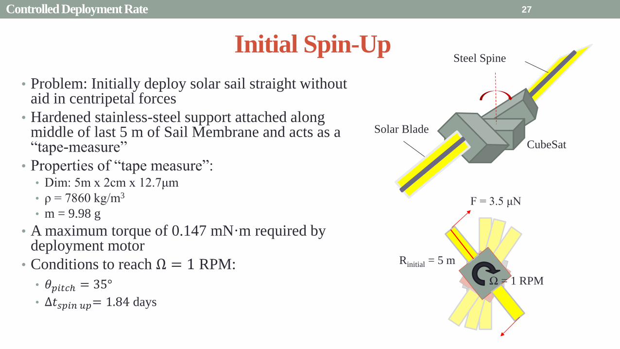
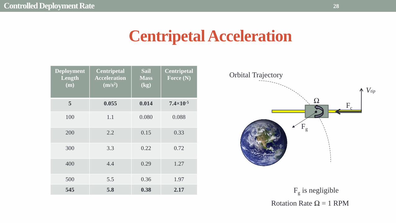
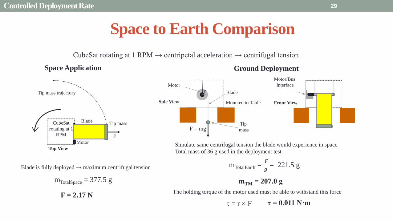
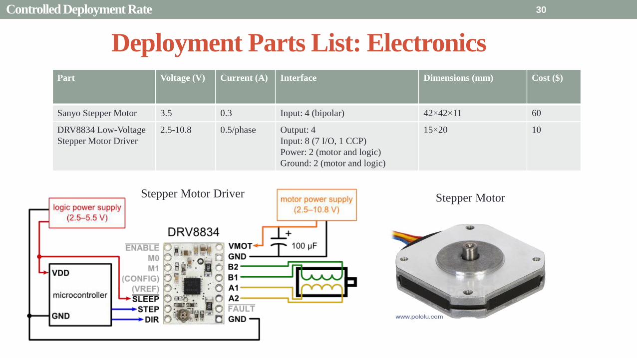
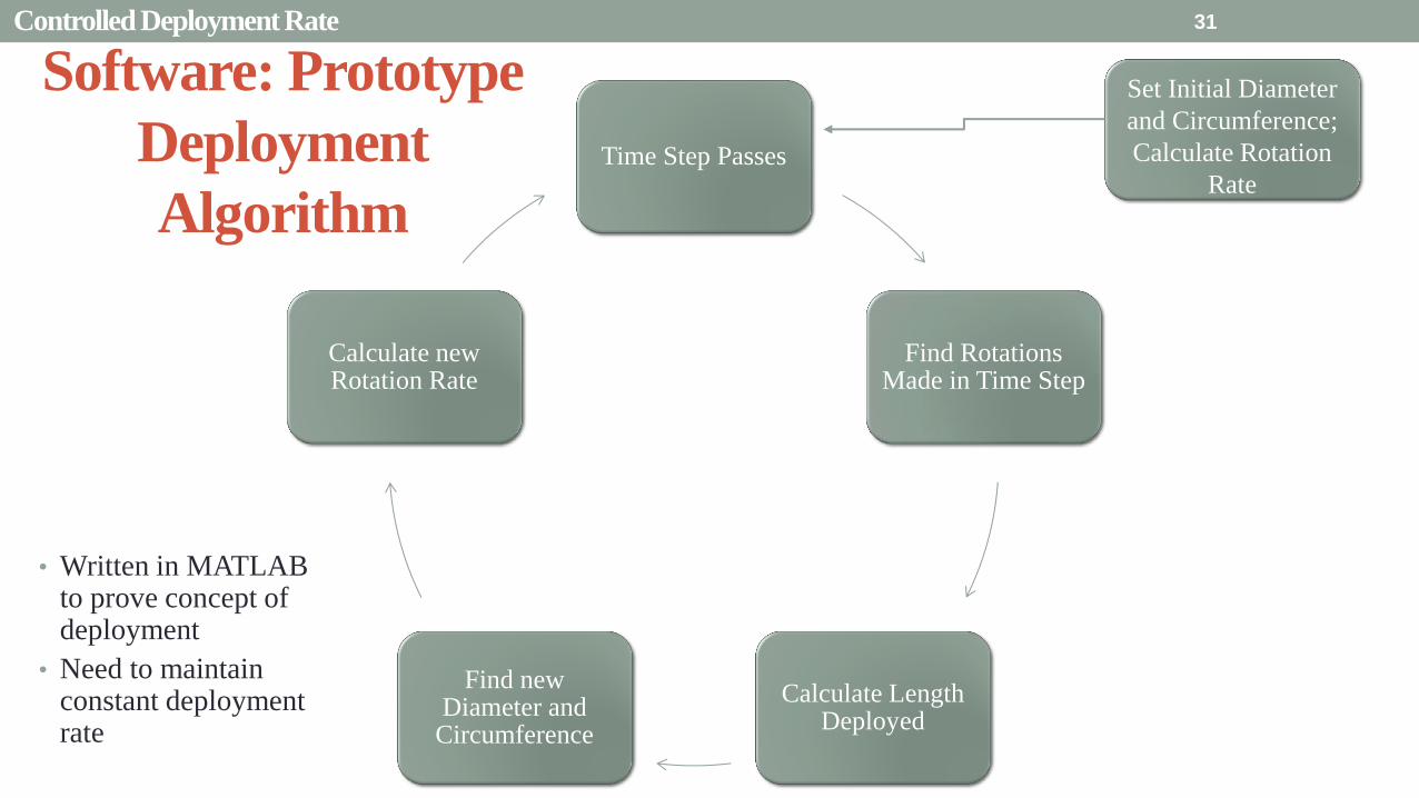
Presentation Sections
bull Purpose and Objectives
bull GHOST Design Solution
bull Critical Project Elements
bull Requirement Satisfaction
bull Controlled Deployment Rate
bull Pitching
bull Survive Launch
bull ElectronicSoftware Integration
bull Manufacturing the CubeSat
bull Summary
bull Remaining Risks
bull Verification and Validation of Design
bull Project Planning
32
The Need for plusmn 90deg Range of Pitch
Blade
Pitch θ
Condition (Profile Description)
0deg Max Thrust (Collective Blade Surface
Normal to Sunlight)
plusmn 35deg Max Torque (Collective) or Max In-Plane
Thrust (1P Cyclic)
plusmn 90deg No Thrust (Collective Blades Edge on to
Solar Wind)
Full 180deg range of motion for blade pitch necessary for spacecraft to have full capabilities of
controlling the thrust vector See Appendix for further information
33 Pitching
Pitching Parts List Electronics
Part Voltage (V) Current (A) Interface Dimensions (mm) Cost ($)
FAULHABER 2036
BLDC Motor
5 02 Input 3 phase
Sensors 3 HALL
Power 1
36times20 (diameter) 230
Atmel ATA6832-DK
Brushless DC Motor
Controller
5 01 Output 3 phase
Input 1 Serial 2 IO
45times45 208
2 Channel IE2-1024
Encoder
5 04 Output 4 I0
Power 1
165times15 (diameter) 225
34
2036 BLDC Motor
Pitching
Servo Controller
bull Bypass LIN input for direct interface with potentiometer
(Serial input use DAC from microcontroller)
35 Pitching
Pitching Software
Pitch Profile Command Sent
Find corresponding
sinusoid equation for pitching
Command servo to turn to angle in
pitching sinusoid
Compare to Encoder Angle
Given a pitch profile the software will
bull Find the corresponding sinusoid command for the
servos
bull Step through those angles over the time period
bull Compare commanded angle to encoder feedback
bull Adjust for accuracy
Pitching 36
Presentation Sections
bull Purpose and Objectives
bull GHOST Design Solution
bull Critical Project Elements
bull Requirement Satisfaction
bull Controlled Deployment Rate
bull Pitching
bull Survive Launch
bull ElectronicSoftware Integration
bull Manufacturing the CubeSat
bull Summary
bull Remaining Risks
bull Verification and Validation of Design
bull Project Planning
37
Canisterized Satellite Dispenser CSD
bull 6U fits into CSD during launch
bull Gives extra clearance on each side bull Allows for locking mechanism outside the 6U
bull Available with Alum 6061
bull Pushed into orbit on ldquoTabrdquo structure bull Additional tabs added below CubeSat base
bull Able to separate tabs for each separate section
38 Survive Launch
Structural Integrity of Pitching Axle and Selection of
Material
bull Aluminum 6061
bull Lightweight (density of 27gcc)
bull Very strong
bull Inexpensive
bull Pitching Axle ndash rod 1 cm in diameter
bull If made of Aluminum 6061
bull Can withstand shear force of 162 kN (~3600 lbs)
bull Does not take into account ability of motor to withstand torque
F (from Solar
Sail)
τ
39 Survive Launch
Pitching Axle
Launch Locks
bull Sierra Nevada SP-5025 pin puller
bull 350 lbf (1500 N) of shear load
bull Powered by a single timed power pulse to one of
the redundant heater circuits
bull SP -5025 greatly exceeds budget so manual
screw and bolt sized appropriately simulate
launch locks in the prototype
40
SP-5025
SP-5025
Deployed
Stowed
Simulated
Launch Locks
Survive Launch
Credit to SNC
Secure Blade Tip Mass
bull C-brackets attached to exterior walls stabilize tip mass vertically and horizontally
bull Cylindrical tip mass fits securely in brackets on both sides
bull Holding torque of stepper motor and tape-measure material holds tip mass in towards rolled blade
bull Within outer limit required by CSD
41
16 cm
075 cm 2 cm
Survive Launch
Presentation Sections
bull Purpose and Objectives
bull GHOST Design Solution
bull Critical Project Elements
bull Requirement Satisfaction
bull Controlled Deployment Rate
bull Pitching
bull Survive Launch
bull ElectronicsSoftware Integration
bull Manufacturing the CubeSat
bull Summary
bull Remaining Risks
bull Verification and Validation of Design
bull Project Planning
42
Service Loop
Power and input wires needed in for stepper
motor in deployment module
bull 4 12A rated wires AWG 21 D = 073 mm
bull Full loop around pitching axle to allow for
plusmn90deg rotational freedom
bull 1 cm diameter hole through each plate
bull Current must run throughout launch to
keep holding torque
bull Need not worry about freezing later in mission
Wires (red) exit opening in wall loops around
pitching axle enters opening in opposite wall
43 ElectronicsSoftware Integration
Electrical Block Diagram
Micro-
controller
35 V Supply
Stepper
Driver
Stepper
Motor
H4
H5
H3
H6
Key IO
CCP
Power
Serial
GND
Sensor
VDD
M0
M1
ENABLE
CONFIG
GND
DIR
STEP
E0
E2
B2
B1
A1
A2
VMOT GND VDD
5 V Supply
GND
Servo
Driver 1
Servo 1 TX RX
P G A B C
5V GND U V W Servo
Driver 2
Servo 2
P G A B C
5V GND C2 C3 C4 U V W
Encoder
J2 J3 J4 J5 J6 J7
VDC G
C0
(Speed Set)
C0
(Speed Set)
RS 232
DAC
A B C
Encoder VDC G A B C
B5 B4
A3
A7
B7
B6
D4
D3
D4 D3
C2 C3 C4
VoutA
VoutB
SCLK CS
DIN
GND
Tin Rout Vin GND
VDD
A4
SLEEP
FAULT H0
E1
44 ElectronicsSoftware Integration
Microcontroller PIC18F87K22
Board Requirements
bull Serial output for communication with computer
and servomotor controller
bullDAC used for servomotor communication
bull I0 ports for stepper driver interface
bull CCP port for stepper driver interface
bull Header pins for the encoder interface
Total
18 IO
1 CCP
1 TXRX
bull Would need more IO and CCP ports for a second
stepper motor driver
bull Unused ports 37 IO and 10 CCPECCP
ElectronicsSoftware Integration
PCB Design
bull 2 Layer Board
bull FR4 material
bull 1 oz Copper traces
bull Estimated Dimension = 5times5 cm
bull (See Appendix for Electrical Schematic)
EasyPIC PRO
v7 Pinout
80 Pin Development
Board
ElectronicsSoftware Integration
Incompatible Industrial Boards
Presentation Sections
bull Purpose and Objectives
bull GHOST Design Solution
bull Critical Project Elements
bull Requirement Satisfaction
bull Controlled Deployment Rate
bull Pitching
bull Survive Launch
bull ElectronicsSoftware Integration
bull Manufacturing the CubeSat
bull Summary
bull Remaining Risks
bull Verification and Validation of Design
bull Project Planning
47
Manufacturing In-House vs Purchasing
48
Part In-House Purchase Details
CubeSat walls Aluminum will be purchased with correct thickness and
manufactured to needed dimensions
Blade and pitching axle Axles can be cut down to needed length
Corner brackets Brackets can be altered to fit needed dimensions
S-brackets and C-brackets Will have to be machined to fit strict dimensions
Tip mass Tip mass can be cut down to needed length
Tape-measure material Purchased from McMaster-Carr
Solar sail blade material Blade material is provided for free by NASA LaRC
Launch Locks Launch locks we will use are a screw and bolt
Launch Tabs for CSD Tabs must meet strict dimensions to fit into CSD from
Planetary Systems Corporation
Hub to attach pitching axle to blade module Will have to be machined to meet needed dimensions
Screwsnutsbolts All can be purchased in various sizes and lengths
Motorsencoders and motor drivers All purchased to meet necessary requirements
Electronics board Will have to be made to accommodate needed electronics
Stabilizers to hold pitching motors Will have to be machined to properly fit around motors
Manufacturing the CubeSat
Assembly Procedure
49 Manufacturing the CubeSat
Bonding Mylar to Spool and Stiff Material
bull Loctite Super Glue Professional
bull Shear strength of 01 Nmm2
bull Cross-Sectional Area = 6575 mm2
bull Shear Stress = 33e-4 Nmm2
bull Blade will retain 4 rolls around axle at
final length
bull Loctite to bond stainless steel stiff
material to Mylar and to spool
F = mg = 217 N
Motor
Blade frac14 of roll glued
50 Manufacturing the CubeSat
Fixing Deployment Motor to S-Bracket
51
bull Deployment stepper motor is attached to S-bracket
bull S-bracket stabilized to back of blade deployment
module and vertical CubeSat walls
bull Motor is capable of being screwed directly to S-bracket
bull S-bracket has thickness of 18 inch
Holes for screws to
stabilize S-bracket
Hole for motor shaft
or press-fit ball
bearing to attach to
blade axle
Holes to screw motor
to S-bracket
Manufacturing the CubeSat
Pitching Axle Interfaces
bull Pitching axle to motor axle
bull Motor axle (smaller) fits into pitching
axle (larger) using set-screws
bull Pitching Axle to Blade Reel
Module
bull Axle fixed by set screws inside a hub
52
Pitching Axle
Hub
Motor Axle
4 Set Screws
Manufacturing the CubeSat
Presentation Sections
bull Purpose and Objectives
bull GHOST design solution
bull Critical Project Elements
bull Requirement Satisfaction
bull Controlled Deployment Rate
bull Pitching
bull Survive Launch
bull ElectronicSoftware Integration
bull Manufacturing the CubeSat
bull Summary
bull Remaining Risks and Mitigations
bull Verification and Validation of Design
bull Schedule and remaining work
53
Requirements Satisfaction
Aspect Requirement GHOST Specification
Mass 1 kgU 288 kg
Volume lt= 12U 6U
Life Span 4 months Greater than 4 months
Space Applicable
While design does not need to be
space worthy it should be applicable
to being used in space
All components are picked for
realistic use in space with minimal
cost parts and increased life span
54 Summary
Requirements Satisfaction
Aspect Requirement GHOST Specification
Characteristic Acceleration ac ge 01 mms2 ac = 03868 mms2
Sail Aspect Ratio AR ge 1001 AR = 38931
Sail Deployment Speed 1 cms le 10cms ~5 cms
Pitching Range Ability to pitch blades plusmn 90deg Ability to pitch blades plusmn 90deg
Pitching Coordination Multiple blade coordination when
pitching
Can pitch both blades at once either to
same angle or opposite angles
55 Summary
Presentation Sections
bullPurpose and Objectives
bullGHOST Design Solution
bullCritical Project Elements
bullRequirement Satisfaction
bullRemaining Risks
bullVerification and Validation of Design
bullProject Planning
56
Design Risks
Severity
Likelihood Marginal Major
Often Pitch angle error root not
following tip
Occasional Power loss COMM loss
Structural survivability
pitching motor failure
Improbable Small tear in Mylar Deploy too fast stowage
and deployment of Mylar
Axle failure
launch fail
space dust
deployment motor failure
57 Remaining Risks
Logistical Risks
Severity
Likelihood Minor Marginal Major
Often Parts delayed due to US
Postal Service
Occasional Structural consultation
unavailable
Ball vibrations test is not
available machine parts
not done on schedule
Government shutdown and
we canrsquot get Mylar or help
from NASA
Improbable No time for pitching test
High Bay in Fleming is
unavailable motors donrsquot
show up
58 Remaining Risks
Financial Risks
Severity
Likelihood Minor Marginal Major
Often Repurchase parts
Occasional Motor breaks Price of shake table
Improbable Hyper inflation
59 Remaining Risks
Presentation Sections
bullPurpose and Objectives
bullGHOST Design Solution
bullCritical Project Elements
bullRequirement Satisfaction
bullRemaining Risks
bullVerification and Validation of Design
bullProject Planning
60
Deployment System
Validate that the blade is deployed at a constant rate of 1-10 cms in a high bay
room
Verify that the motor can deploy at constant rate
Verify with test that the deployment system does not use more than the maximum power available of 10W
Validate that the blade can successfully deploy a blade with tape measure
material at a constant rate along ground
Verify with demonstration that the tape measure material can extend length of
blade
Verification and Validation
Verification and Validation
61
Blade Deployment Testing Information
bull Location Prof Frewrsquos High Bay Lab
bull Scheduled MarchApril with late night access to avoid
scheduling conflicts
bull Measurement Tape measure for distance and video
camera for time
bull Power Delivered 6253A Dual DC Power Supply
delivers 0-20 V and 0-3A
Tape measure
marking
distance up
wall
Kinematic Model
bull Torque from motor drives a constant velocity deployment
120591119898119900119905119900119903 = 120591119903119900119897119897 + 120591119901119906119904ℎ119894119899119892 119879119872 minus 120591119892119903119886119907119894119905119910 119879119872
120591119903119900119897119897 =119889119868119903119900119897119897
119889119905120596119903119900119897119897 + 119868119903119900119897119897
119889120596119903119900119897119897
119889119905
120591119901119906119904ℎ119894119899119892 119879119872 =119889119898119890119909119905
119889119905119903119903119900119897119897119907 + 119898119890119909119905
119889119903119903119900119897119897
119889119905119907
120591119892119903119886119907119894119905119910 119879119872 = 119898119890119909119905119903119903119900119897119897119892 bull 120649119945119952119949119941119946119951119944 = 120782 120782120790120787 N∙m 120649119950119952119941119942119949119950119938119961 = 120782 120782120782120789 N∙m
Power Supply
Verification and Validation
CubeSat Wire
62
Pitching System
Validate that the blade reel modules experience coordinated pitching
Verify that one blade reel module experiences periodic
motion
Verify that the blade reel module rotates to 0deg upon
initialization
Verify that the blade pitches to a given command
angle
Verify that the motorencoder system does not exceed power
available
Verification and Validation
Verification and Validation
63
Verify Pitching Angle Experiment Equipment and Specs
bull Use R60D RVIT (Rotary Variable Inductance Transducer) sensor to measure angles attaches to pin (red) in line with pitching axis bull Measures ranges of plusmn60deg rotation
bull Input Voltage = plusmn15 V
bull Output Voltage = plusmn75 V
bull Resolution = 0125 Vdeg
bull 119891119898119886119909 = 20 Hz
bull Use AD524 Precision Amplifier Instrumentation for signal conditioning bull Input Voltage plusmn10 V
bull Output Voltage plusmn10V
bull Requires Supply Voltage plusmn15
bull Use NI 9201 bull Input Voltage plusmn10 V
bull Has a USB output that can connect to a computer where vi program records
Experiment Set-Up
R60D RVIT
AD524
NI 9201 PC via USB
Verification and Validation 64
Verify Periodic Motion Experiment
bull Using the R60D RVIT set-up to measure deflection angles
bull With data of the angle deflection 120579 angular velocity 120596 and angular acceleration 120572 can be measured bull Motor restriction 120591119898119886119909 = 032 Nmiddotm
bull Model restriction 120596119898119886119909 = Ω2 if Ω = 2rpm 120596119898119886119909 = 02094 rads
Validation Model
bull R60D RVIT measures plusmn60deg deflection angles bull Critical condition blade reel module pitches plusmn90deg Ω=2rpm
bull 120572119888 = 00172 rads2 and 120596119898 = 0164 rads thus 120591119898 = 0083 mNmiddotm (119868119898119900119889 = 00048 kgmiddotm2)
120579 119905 120596 119905 120572 119905
Verification and Validation 65
Verification and Validation
Structural System
Validate that the final design can survive launch by using a shake
table
Verify the structural integrity by demonstrating that all stationary parts are
static
Verification and Validation 66
Trade Study FEM vs Vibration Table
Cost Time Experience
Similar to
Actual
Launch
Guaranteed Can
Do Total
FEM 4 1 1 3 4 215
Vibration
Table 2 3 4 4 2 32
Weight () 5 30 25 20 20 100
67 Verification and Validation
See Appendix for Full Trade Study
Validate Structural Stability
bull Will use a shaker table from Ball Aerospace
bull Cost = $250hr
bull Schedule Time to be determined in April
bull Specifications Peak vibration occurs with 34g at
frequency of 16 Hz (Saturn V)
bull Will be verified by examining the structural integrity
of the manufacturing
Verification and Validation 68
CubeSat
Shake Table
Presentation Sections
bullPurpose and Objectives
bullGHOST Design Solution
bullCritical Project Elements
bullRequirement Satisfaction
bullRemaining Risks
bullVerification and Validation of Design
bullProject Planning
69
Organizational Chart
Mark
Dolezal
Emily
Proano
Lauren
Persons
Casey
Myers
Nicholas
Busbey
Taylor
Smith
Karynna
Tuan
Megan
Scheele
Project
Manager
Software
Lead
Electrical
Lead
Systems Test and
Safety
Manufacturing
Lead Mechanics
Lead
CFO and
Materials
Lead
Organizing
team
meetings
Supporting
other leads
Non CPE
Tasks
Deployment
Control
Pitching
Control Motors and
Electronics
Power
Integrate
all system Perform
and Plan
tests
Manufacture
all in-house
parts
SolidWorks
Keep track
of financial
spending
Right
materials
are being
utilized
CubeSat
Assembly
Specific
System
Requirements
70 Project Planning
GHOST
Materials Mechanical Electrical Software Documents
Shake Table
Vibration
Analysis
Mechanical
Layout
Power Budget Pitch Control
Algorithm
Deployment
Rate Control
Algorithm SolidWorks
Model
Electrical
Wiring Layout
Thermodynamic
Analysis of
Electronic System
Mass Budget
Prototype of
CubeSat Bus
Motor
Subsystem
CDR
FFR
Spring
Schedule
Financial
Budget
Work Breakdown Structure (WBS)
Mylar from
NASA
Spin Up
Algorithm
Emergency
StopRestart System
71 Project Planning
PCB Design
Spring
Documents
113 120 127 203 210 217 224 303 310 317 324 331 407 414 421 428
MSR TRR SFR PFR
Time (date)
Purchase
motorsdrivers
Preliminary code
Electronic
integration
Test code
Electronicscode
interface
Purchase
raw materials
Manufacture frame
Assemble bus
Manufacture
remaining parts
Integrate system
Deployment test
Pitching test
Vibration test
Ta
sks
72
GHOST Spring Schedule
Project Planning
Planned Uncertainty
Key
Test Plan Test Scheduled Facility Specialized Equipment
Verify Pitch Angle 317 ITLL R60D RVIT NI 9201 AD524 Oscilloscope bench
power source
Zero Pitch Angle 317 ITLL R60D RVIT NI 9201 AD524 Oscilloscope bench
power source
Measure power used in
pitchdeployment 317 ITLL Ammeter voltmeter bench power source
Verify constant deployment 324 ITLL Firewire camera bench power source
ASEN2003BallTrackervi
Verify periodic motion 324 ITLL R60D RVIT NI 9201 AD524 Oscilloscope bench
power source
Validate tape measure ground
deployment 331 ITLL
Bench power source tape measure stop watch rollers
for tip mass
Validate coordinated pitching 331 ITLL R60D RVIT NI 9201 AD524 oscilloscope bench
power source
Validate 1g blade deployment 331-414 Prof Frew
high bay
Portable 6253A Dual DC Power Supply ladder tape
measure video camera
Validate launch ready 414 Ball Aero Shake Table
Project Planning 73
Cost Table ndash Structural Components
Part Price per
part NeededVolume Needed Total Price Supplier
Aluminum 6061 Sheet
(18rdquo thick) $ 8976 2ft times 2ft times 18 in $ 8976 The Metals Depot
Aluminum 6061 rod
(14 in diameter) $280 2 ft $280 The Metals Depot
Aluminum6061 rod
(716 in diameter) $494 2 ft $494 The Metals Depot
Steel Corner Brackets
(34rdquo times 12rdquo)
$197 4
braces 16 $788 Home Depot
Hardened 302 Stainless
Steel $3300 2 cm times 5 m times 127 microm $3300 McMaster-Carr
Total $11834
74 Project Planning
Cost Table ndash Electrical Components
Part Price per
part Needed Total Price Supplier
Sanyo Stepper Motor $ 5995 2 $11990 Pololu Electronics and Robotics
DRV8834 Low-Voltage Stepper
Motor Driver $995 2 $1990 Pololu Electronics and Robotics
FAULHABER 2036 BLDC
Servo Motor $23000 2 $46000 MicroMo Micro Motion Solutions
Atmel ATA6832-DK Brushless
DC Motor Controller $20800 2 $41600 Atmel
Encoder AU-ZSD1000A $22500 2 $45000 MicroMo Micro Motion Solutions
PIC18F87K22 Microcontroller $500 1 $500 Microchip
AD-524 Signal Converter $1767 1 $1767 Agilent
Total $148847
75 Project Planning
Questions
76
References
bull wwwloctiteproductscom
bull Vallado D A Fundamentals of Astrodynamics and Applications
bull Guerrant D Lawrence D Heaton A Earth Escape Capabilities of the Heliogyro Sail AIAA Paper
bull wwwspaceflightnowcom
bull Guerrant D HGVizGuim MATLAB Program
bull httpwwwmicromocombrushless-dc-motorsaspx
bull httpwwwfaulhabercomservletcomitmrwawservletAnzeigefremdaufruf=jaampkdid=40929ampsprachid=1amphtdigurl=n169933i95222html
bull httpwwwpololucom
bull httpasmmatwebcomsearchSpecificMaterialaspbassnum=MA6061t6
bull httpwwwruagcomthermalSpace_Thermal_HardwareMulti_Layer_Insulation
bull Helgesen Bryan Sierra Nevada Corporation
77
GyroSail Launch Configuration and Deployment Sequence
78
1 Launch configuration (6U) 2 Blade reel modules pitch to zero Fits within a 6U or 12U dispenser
3 PV arrays deploy
Other array configurations are possible
williamkwilkienasagov NASA PREDECISIONAL - FOR DISCUSSION PURPOSES ONLY
78 Appendix
GyroSail Primary Bus Systems Based on modified JPLU MichUCLACal PolyUT INSPIRE bus
williamkwilkienasagov
05U cold gas thruster ACS for detumbling
and initial spin-up
(httpwwwaustinsatnet)
05U EPS battery CampDH UHF backup
comms (U Mich) 05U DSN-compatible X-band
communications (JPL)
05U COTS star trackerimager ADC (BCT) sail
module processor (CU)
Klesh A et al 2013 ldquoINSPIRE Interplanetary NanoSpacecraft Pathfinder In Relevant Environmentrdquo Proceedings of the AIAAUSU Conference on Small Satellites Around the Corner SSC13-
XI-8 httpdigitalcommonsusuedusmallsat2013all2013127
NASA PREDECISIONAL - FOR DISCUSSION PURPOSES ONLY
79 Appendix
COMM Subsystem
bull 18 m Ka-band antennas at White
Sands New Mexico
bull Goddard Space Flight Center
Greebelt Maryland USA
supplied the Mulemba Space
Center in Angola
80 Appendix
Orion Crew
Module
6U Canisterized Satellite
Dispenser (CSD) ESPA Ring
Spacecraft
Adapter
Interim Cryogenic Propulsion
Stage (ICPS)
Secondary Payload Attachment to SLS
The SLS design is currently going through CDR An ESPA
ring is not currently in place but is mentioned in the SLS
CONOPS in order to accommodate secondary payloads
81 Appendix
Max Thrust Condition Collective 90deg pitch profile
Max thrust normal to orbital plane
(Halo orbits orbital plane rotation ie
inclination change)
82
Credit to Dan Guerrant
Appendix
Max Thrust Condition
F vs β M vs β
83
Credit to Dan Guerrant
Appendix
No Thrust Condition Collective 0deg pitch profile
Zero thrust
84
Credit to Dan Guerrant
Appendix
No Thrust Condition
F vs β M vs β
85
Credit to Dan Guerrant
Appendix
Max Torque Condition Collective 35deg pitch profile
Max torque used for spinning up sc
(opposite orientation for despinning)
86
Credit to Dan Guerrant
Appendix
Max Torque Condition
F vs β M vs β
87
Credit to Dan Guerrant
Appendix
Max In-Plane Thrust Condition Cyclic 35deg pitch profile
Max thrust in in-plane (d2) direction for orbit raising
88
Credit to Dan Guerrant
Appendix
Max In-Plane Thrust Condition
F vs β M vs β
89
Credit to Dan Guerrant
Appendix
Orbit Raising
F
90 Appendix
Thermal Space Concerns
bull Material Concerns
bull Aluminum 6061 -196 degC to 160deg C
bull Electronics Concerns
bull Typical Operating Temperature -55 to 80 degC
bull Countermeasures
bull Multi-layer Insulation AAErotherm S10-190
bull (0005 ndash 0035 Wm2K)
bull Battery operated heaters for pre-sail deployment
Multi-layer Insulation
Layer 1 1 x Outer layer
Layer 2 8 x 03 mil VDAPolyimideVDA perf
8 x Woven Polyester netting
Layer 3 1 x Outer layer
Layer 4 1 x Woven Polyester netting
91 Appendix
Rolled Up Blade Reel Calculation Optimal Sail Length 545 m ndash Sail chord of 14 cm
Max Diameter of Spool 598 cm
Diameter of Axle 05 cm
Length of Stiff Material 5 m
Dimension of Stiff Material 5 m times 2 cm times 127 microm
92 Appendix
Torque calculation
bull Note current calculated via T=kI (where T is torque I is amp k is the torque
constant specific to the motor)
T = kI
(k = 005 NmA)
93 Appendix
Servo Controller
94 Appendix
Encoder Dimensions and Interface
bull FAULHABER IE2-1024
95 Appendix
Stepper Motor Torque
96 Appendix
Motor Phases (Stepper)
97 Appendix
98 Appendix
99 Appendix
100 Appendix
101 Appendix
Microcontroller
102 Appendix
ATA6832 Phase Output Chip
103 Appendix
ATA6624 Bypassed Chip
bull Bypassed chip
on servo controller
104 Appendix
Power Budget
105 Appendix
Wire Gauge
bull Stepper Motor 26AWG (04 mm diameter)
bull Servomotor 24 AWG (051 mm diameter)
bull Encoder 24 AWG
Voltage Drop () AWG Max Gauge
001 5
01 15
1 25
5 32
NOTE Voltage drop calculated at 1A and 40 cm of wire
106
24 AWG Wire
Appendix
Trade Study ndash FEM vs Vibration Table
Factor 4 3 2 1
Cost No money 0 gt C gt $100 $100 gt C gt $300 $300 lt C
Time 0 min lt T lt 30 min 30 min lt T lt 2 hrs 2 hrs lt T lt 1 day 1day lt T
Experience Everyone has
experience
A couple people
know how to
1 person has
experience
No one has
experience
Similar To Actual
Launch Simulate real launch
Doesnrsquot have all
variables experienced
Has only a couple
similarities
No similarities to
launch
Guaranteed Can Do
Donrsquot need any
outside equipment or
help
Need outside
equipment but
guaranteed use
Need outside
equipment but own
work at higher
priority
Need outside
equipment but canrsquot
use
Scoring
107 Appendix
Weighting
Weight () Category Reasoning
5 Cost Have a lot of extra $ in the budget
30 Time Have a strict schedule but not a main focus of the
project
25 Experience If no one has experience it will take a lot of time
20 Similar to Actual Launch Needs to be like actual launch
20 Guaranteed Can Do Needs to be able to accomplish but not the most
important focus
108 Appendix
Finite Element Method (FEM)
Objectives Description ProCon
Cost No money because one of us
would do it Pro
Time A lot of time to learn and then
perform FEM Con
Experience No one in group has FEM
experience Con
Similar to Actual Launch Very similar to actual launch Pro
Guaranteed Can Do All we need is paper pen and
theory to do Pro
109 Appendix
Vibration Table
Objective Description ProCons
Cost $250hr Con
Time A hour on the table should simulate
launch Pro
Experience Donrsquot need experience to run
vibration table Pro
Similar to Actual Launch Actually putting our system through
vibration stress Pro
Guaranteed Can Do No guarantee but most likely can Con
110 Appendix
SpinUp State
1 Check value of SpinUp to see if satellite is already spun up
bull Continue if satellite is not already spun-up
2 Deploy the tape stiffened length of the blade
3 Pitch to the spin up angle
4 Wait until characteristic angular velocity is reached
5 Pitch to pre-deployment position
6 Save SpinUp as completed
Appendix 111
Deployment State
1 Check if satellite has been spun up yet
bull Continue if it has
2 Check if blades are already deployed
bull Continue if they havenrsquot
3 Run deploy algorithm until blades are fully deployed
4 Save value saying blades have been deployed
Appendix 112
Pitching State
1 Check if satellite has been spun up
bull Continue if satellite has been spun up
2 Check if blades have been deployed
bull Continue if blades have been deployed
3 Look at commanded pitch profile
4 Find correlated sinusoid command
5 Command servo to pitch angle for the time in the orbit
6 Continue until given a new pitch command
Appendix 113
Emergency Stop
1 Save which state was interrupted
2 Save last position in interrupted
state
3 Wait until Restart command is
received
1 Check two previous states to see
what is being restarted
2 Look at saved last position in
state being restarted
3 Adapt the algorithm of the state
to continue where left off
Restart
Appendix 114
Comparison with Previous Heliogyro Concepts MIT (1989) NASA (2011) GHOST
Total sail craft mass (kg) 18 84
288 (6)
Characteristic acceleration ac
(mms2) 06 10 03868 (01854)
Sail reflective area (m2) 1200 960 1526
Non-sail mass (kg) 5 5 --
Number of sail blades 8 6 2
Blade chord (m) 15 08 014
Blade length (m) 100 200 545
Rotational period (minutes) 3 3 1
Blade root stress (Pa) 8650 34000 --
Blade root allowable stress (Pa) 55 M 55 M --
Blade root tension load (N) 01 007 --
115 Appendix
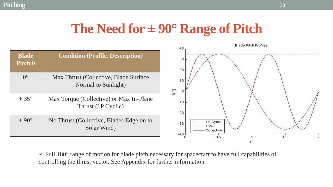
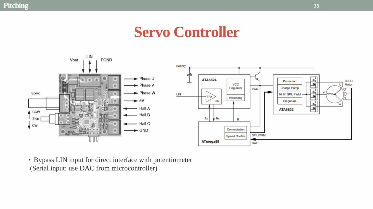
Servo Controller
bull Bypass LIN input for direct interface with potentiometer
(Serial input use DAC from microcontroller)
35 Pitching
Pitching Software
Pitch Profile Command Sent
Find corresponding
sinusoid equation for pitching
Command servo to turn to angle in
pitching sinusoid
Compare to Encoder Angle
Given a pitch profile the software will
bull Find the corresponding sinusoid command for the
servos
bull Step through those angles over the time period
bull Compare commanded angle to encoder feedback
bull Adjust for accuracy
Pitching 36
Presentation Sections
bull Purpose and Objectives
bull GHOST Design Solution
bull Critical Project Elements
bull Requirement Satisfaction
bull Controlled Deployment Rate
bull Pitching
bull Survive Launch
bull ElectronicSoftware Integration
bull Manufacturing the CubeSat
bull Summary
bull Remaining Risks
bull Verification and Validation of Design
bull Project Planning
37
Canisterized Satellite Dispenser CSD
bull 6U fits into CSD during launch
bull Gives extra clearance on each side bull Allows for locking mechanism outside the 6U
bull Available with Alum 6061
bull Pushed into orbit on ldquoTabrdquo structure bull Additional tabs added below CubeSat base
bull Able to separate tabs for each separate section
38 Survive Launch
Structural Integrity of Pitching Axle and Selection of
Material
bull Aluminum 6061
bull Lightweight (density of 27gcc)
bull Very strong
bull Inexpensive
bull Pitching Axle ndash rod 1 cm in diameter
bull If made of Aluminum 6061
bull Can withstand shear force of 162 kN (~3600 lbs)
bull Does not take into account ability of motor to withstand torque
F (from Solar
Sail)
τ
39 Survive Launch
Pitching Axle
Launch Locks
bull Sierra Nevada SP-5025 pin puller
bull 350 lbf (1500 N) of shear load
bull Powered by a single timed power pulse to one of
the redundant heater circuits
bull SP -5025 greatly exceeds budget so manual
screw and bolt sized appropriately simulate
launch locks in the prototype
40
SP-5025
SP-5025
Deployed
Stowed
Simulated
Launch Locks
Survive Launch
Credit to SNC
Secure Blade Tip Mass
bull C-brackets attached to exterior walls stabilize tip mass vertically and horizontally
bull Cylindrical tip mass fits securely in brackets on both sides
bull Holding torque of stepper motor and tape-measure material holds tip mass in towards rolled blade
bull Within outer limit required by CSD
41
16 cm
075 cm 2 cm
Survive Launch
Presentation Sections
bull Purpose and Objectives
bull GHOST Design Solution
bull Critical Project Elements
bull Requirement Satisfaction
bull Controlled Deployment Rate
bull Pitching
bull Survive Launch
bull ElectronicsSoftware Integration
bull Manufacturing the CubeSat
bull Summary
bull Remaining Risks
bull Verification and Validation of Design
bull Project Planning
42
Service Loop
Power and input wires needed in for stepper
motor in deployment module
bull 4 12A rated wires AWG 21 D = 073 mm
bull Full loop around pitching axle to allow for
plusmn90deg rotational freedom
bull 1 cm diameter hole through each plate
bull Current must run throughout launch to
keep holding torque
bull Need not worry about freezing later in mission
Wires (red) exit opening in wall loops around
pitching axle enters opening in opposite wall
43 ElectronicsSoftware Integration
Electrical Block Diagram
Micro-
controller
35 V Supply
Stepper
Driver
Stepper
Motor
H4
H5
H3
H6
Key IO
CCP
Power
Serial
GND
Sensor
VDD
M0
M1
ENABLE
CONFIG
GND
DIR
STEP
E0
E2
B2
B1
A1
A2
VMOT GND VDD
5 V Supply
GND
Servo
Driver 1
Servo 1 TX RX
P G A B C
5V GND U V W Servo
Driver 2
Servo 2
P G A B C
5V GND C2 C3 C4 U V W
Encoder
J2 J3 J4 J5 J6 J7
VDC G
C0
(Speed Set)
C0
(Speed Set)
RS 232
DAC
A B C
Encoder VDC G A B C
B5 B4
A3
A7
B7
B6
D4
D3
D4 D3
C2 C3 C4
VoutA
VoutB
SCLK CS
DIN
GND
Tin Rout Vin GND
VDD
A4
SLEEP
FAULT H0
E1
44 ElectronicsSoftware Integration
Microcontroller PIC18F87K22
Board Requirements
bull Serial output for communication with computer
and servomotor controller
bullDAC used for servomotor communication
bull I0 ports for stepper driver interface
bull CCP port for stepper driver interface
bull Header pins for the encoder interface
Total
18 IO
1 CCP
1 TXRX
bull Would need more IO and CCP ports for a second
stepper motor driver
bull Unused ports 37 IO and 10 CCPECCP
ElectronicsSoftware Integration
PCB Design
bull 2 Layer Board
bull FR4 material
bull 1 oz Copper traces
bull Estimated Dimension = 5times5 cm
bull (See Appendix for Electrical Schematic)
EasyPIC PRO
v7 Pinout
80 Pin Development
Board
ElectronicsSoftware Integration
Incompatible Industrial Boards
Presentation Sections
bull Purpose and Objectives
bull GHOST Design Solution
bull Critical Project Elements
bull Requirement Satisfaction
bull Controlled Deployment Rate
bull Pitching
bull Survive Launch
bull ElectronicsSoftware Integration
bull Manufacturing the CubeSat
bull Summary
bull Remaining Risks
bull Verification and Validation of Design
bull Project Planning
47
Manufacturing In-House vs Purchasing
48
Part In-House Purchase Details
CubeSat walls Aluminum will be purchased with correct thickness and
manufactured to needed dimensions
Blade and pitching axle Axles can be cut down to needed length
Corner brackets Brackets can be altered to fit needed dimensions
S-brackets and C-brackets Will have to be machined to fit strict dimensions
Tip mass Tip mass can be cut down to needed length
Tape-measure material Purchased from McMaster-Carr
Solar sail blade material Blade material is provided for free by NASA LaRC
Launch Locks Launch locks we will use are a screw and bolt
Launch Tabs for CSD Tabs must meet strict dimensions to fit into CSD from
Planetary Systems Corporation
Hub to attach pitching axle to blade module Will have to be machined to meet needed dimensions
Screwsnutsbolts All can be purchased in various sizes and lengths
Motorsencoders and motor drivers All purchased to meet necessary requirements
Electronics board Will have to be made to accommodate needed electronics
Stabilizers to hold pitching motors Will have to be machined to properly fit around motors
Manufacturing the CubeSat
Assembly Procedure
49 Manufacturing the CubeSat
Bonding Mylar to Spool and Stiff Material
bull Loctite Super Glue Professional
bull Shear strength of 01 Nmm2
bull Cross-Sectional Area = 6575 mm2
bull Shear Stress = 33e-4 Nmm2
bull Blade will retain 4 rolls around axle at
final length
bull Loctite to bond stainless steel stiff
material to Mylar and to spool
F = mg = 217 N
Motor
Blade frac14 of roll glued
50 Manufacturing the CubeSat
Fixing Deployment Motor to S-Bracket
51
bull Deployment stepper motor is attached to S-bracket
bull S-bracket stabilized to back of blade deployment
module and vertical CubeSat walls
bull Motor is capable of being screwed directly to S-bracket
bull S-bracket has thickness of 18 inch
Holes for screws to
stabilize S-bracket
Hole for motor shaft
or press-fit ball
bearing to attach to
blade axle
Holes to screw motor
to S-bracket
Manufacturing the CubeSat
Pitching Axle Interfaces
bull Pitching axle to motor axle
bull Motor axle (smaller) fits into pitching
axle (larger) using set-screws
bull Pitching Axle to Blade Reel
Module
bull Axle fixed by set screws inside a hub
52
Pitching Axle
Hub
Motor Axle
4 Set Screws
Manufacturing the CubeSat
Presentation Sections
bull Purpose and Objectives
bull GHOST design solution
bull Critical Project Elements
bull Requirement Satisfaction
bull Controlled Deployment Rate
bull Pitching
bull Survive Launch
bull ElectronicSoftware Integration
bull Manufacturing the CubeSat
bull Summary
bull Remaining Risks and Mitigations
bull Verification and Validation of Design
bull Schedule and remaining work
53
Requirements Satisfaction
Aspect Requirement GHOST Specification
Mass 1 kgU 288 kg
Volume lt= 12U 6U
Life Span 4 months Greater than 4 months
Space Applicable
While design does not need to be
space worthy it should be applicable
to being used in space
All components are picked for
realistic use in space with minimal
cost parts and increased life span
54 Summary
Requirements Satisfaction
Aspect Requirement GHOST Specification
Characteristic Acceleration ac ge 01 mms2 ac = 03868 mms2
Sail Aspect Ratio AR ge 1001 AR = 38931
Sail Deployment Speed 1 cms le 10cms ~5 cms
Pitching Range Ability to pitch blades plusmn 90deg Ability to pitch blades plusmn 90deg
Pitching Coordination Multiple blade coordination when
pitching
Can pitch both blades at once either to
same angle or opposite angles
55 Summary
Presentation Sections
bullPurpose and Objectives
bullGHOST Design Solution
bullCritical Project Elements
bullRequirement Satisfaction
bullRemaining Risks
bullVerification and Validation of Design
bullProject Planning
56
Design Risks
Severity
Likelihood Marginal Major
Often Pitch angle error root not
following tip
Occasional Power loss COMM loss
Structural survivability
pitching motor failure
Improbable Small tear in Mylar Deploy too fast stowage
and deployment of Mylar
Axle failure
launch fail
space dust
deployment motor failure
57 Remaining Risks
Logistical Risks
Severity
Likelihood Minor Marginal Major
Often Parts delayed due to US
Postal Service
Occasional Structural consultation
unavailable
Ball vibrations test is not
available machine parts
not done on schedule
Government shutdown and
we canrsquot get Mylar or help
from NASA
Improbable No time for pitching test
High Bay in Fleming is
unavailable motors donrsquot
show up
58 Remaining Risks
Financial Risks
Severity
Likelihood Minor Marginal Major
Often Repurchase parts
Occasional Motor breaks Price of shake table
Improbable Hyper inflation
59 Remaining Risks
Presentation Sections
bullPurpose and Objectives
bullGHOST Design Solution
bullCritical Project Elements
bullRequirement Satisfaction
bullRemaining Risks
bullVerification and Validation of Design
bullProject Planning
60
Deployment System
Validate that the blade is deployed at a constant rate of 1-10 cms in a high bay
room
Verify that the motor can deploy at constant rate
Verify with test that the deployment system does not use more than the maximum power available of 10W
Validate that the blade can successfully deploy a blade with tape measure
material at a constant rate along ground
Verify with demonstration that the tape measure material can extend length of
blade
Verification and Validation
Verification and Validation
61
Blade Deployment Testing Information
bull Location Prof Frewrsquos High Bay Lab
bull Scheduled MarchApril with late night access to avoid
scheduling conflicts
bull Measurement Tape measure for distance and video
camera for time
bull Power Delivered 6253A Dual DC Power Supply
delivers 0-20 V and 0-3A
Tape measure
marking
distance up
wall
Kinematic Model
bull Torque from motor drives a constant velocity deployment
120591119898119900119905119900119903 = 120591119903119900119897119897 + 120591119901119906119904ℎ119894119899119892 119879119872 minus 120591119892119903119886119907119894119905119910 119879119872
120591119903119900119897119897 =119889119868119903119900119897119897
119889119905120596119903119900119897119897 + 119868119903119900119897119897
119889120596119903119900119897119897
119889119905
120591119901119906119904ℎ119894119899119892 119879119872 =119889119898119890119909119905
119889119905119903119903119900119897119897119907 + 119898119890119909119905
119889119903119903119900119897119897
119889119905119907
120591119892119903119886119907119894119905119910 119879119872 = 119898119890119909119905119903119903119900119897119897119892 bull 120649119945119952119949119941119946119951119944 = 120782 120782120790120787 N∙m 120649119950119952119941119942119949119950119938119961 = 120782 120782120782120789 N∙m
Power Supply
Verification and Validation
CubeSat Wire
62
Pitching System
Validate that the blade reel modules experience coordinated pitching
Verify that one blade reel module experiences periodic
motion
Verify that the blade reel module rotates to 0deg upon
initialization
Verify that the blade pitches to a given command
angle
Verify that the motorencoder system does not exceed power
available
Verification and Validation
Verification and Validation
63
Verify Pitching Angle Experiment Equipment and Specs
bull Use R60D RVIT (Rotary Variable Inductance Transducer) sensor to measure angles attaches to pin (red) in line with pitching axis bull Measures ranges of plusmn60deg rotation
bull Input Voltage = plusmn15 V
bull Output Voltage = plusmn75 V
bull Resolution = 0125 Vdeg
bull 119891119898119886119909 = 20 Hz
bull Use AD524 Precision Amplifier Instrumentation for signal conditioning bull Input Voltage plusmn10 V
bull Output Voltage plusmn10V
bull Requires Supply Voltage plusmn15
bull Use NI 9201 bull Input Voltage plusmn10 V
bull Has a USB output that can connect to a computer where vi program records
Experiment Set-Up
R60D RVIT
AD524
NI 9201 PC via USB
Verification and Validation 64
Verify Periodic Motion Experiment
bull Using the R60D RVIT set-up to measure deflection angles
bull With data of the angle deflection 120579 angular velocity 120596 and angular acceleration 120572 can be measured bull Motor restriction 120591119898119886119909 = 032 Nmiddotm
bull Model restriction 120596119898119886119909 = Ω2 if Ω = 2rpm 120596119898119886119909 = 02094 rads
Validation Model
bull R60D RVIT measures plusmn60deg deflection angles bull Critical condition blade reel module pitches plusmn90deg Ω=2rpm
bull 120572119888 = 00172 rads2 and 120596119898 = 0164 rads thus 120591119898 = 0083 mNmiddotm (119868119898119900119889 = 00048 kgmiddotm2)
120579 119905 120596 119905 120572 119905
Verification and Validation 65
Verification and Validation
Structural System
Validate that the final design can survive launch by using a shake
table
Verify the structural integrity by demonstrating that all stationary parts are
static
Verification and Validation 66
Trade Study FEM vs Vibration Table
Cost Time Experience
Similar to
Actual
Launch
Guaranteed Can
Do Total
FEM 4 1 1 3 4 215
Vibration
Table 2 3 4 4 2 32
Weight () 5 30 25 20 20 100
67 Verification and Validation
See Appendix for Full Trade Study
Validate Structural Stability
bull Will use a shaker table from Ball Aerospace
bull Cost = $250hr
bull Schedule Time to be determined in April
bull Specifications Peak vibration occurs with 34g at
frequency of 16 Hz (Saturn V)
bull Will be verified by examining the structural integrity
of the manufacturing
Verification and Validation 68
CubeSat
Shake Table
Presentation Sections
bullPurpose and Objectives
bullGHOST Design Solution
bullCritical Project Elements
bullRequirement Satisfaction
bullRemaining Risks
bullVerification and Validation of Design
bullProject Planning
69
Organizational Chart
Mark
Dolezal
Emily
Proano
Lauren
Persons
Casey
Myers
Nicholas
Busbey
Taylor
Smith
Karynna
Tuan
Megan
Scheele
Project
Manager
Software
Lead
Electrical
Lead
Systems Test and
Safety
Manufacturing
Lead Mechanics
Lead
CFO and
Materials
Lead
Organizing
team
meetings
Supporting
other leads
Non CPE
Tasks
Deployment
Control
Pitching
Control Motors and
Electronics
Power
Integrate
all system Perform
and Plan
tests
Manufacture
all in-house
parts
SolidWorks
Keep track
of financial
spending
Right
materials
are being
utilized
CubeSat
Assembly
Specific
System
Requirements
70 Project Planning
GHOST
Materials Mechanical Electrical Software Documents
Shake Table
Vibration
Analysis
Mechanical
Layout
Power Budget Pitch Control
Algorithm
Deployment
Rate Control
Algorithm SolidWorks
Model
Electrical
Wiring Layout
Thermodynamic
Analysis of
Electronic System
Mass Budget
Prototype of
CubeSat Bus
Motor
Subsystem
CDR
FFR
Spring
Schedule
Financial
Budget
Work Breakdown Structure (WBS)
Mylar from
NASA
Spin Up
Algorithm
Emergency
StopRestart System
71 Project Planning
PCB Design
Spring
Documents
113 120 127 203 210 217 224 303 310 317 324 331 407 414 421 428
MSR TRR SFR PFR
Time (date)
Purchase
motorsdrivers
Preliminary code
Electronic
integration
Test code
Electronicscode
interface
Purchase
raw materials
Manufacture frame
Assemble bus
Manufacture
remaining parts
Integrate system
Deployment test
Pitching test
Vibration test
Ta
sks
72
GHOST Spring Schedule
Project Planning
Planned Uncertainty
Key
Test Plan Test Scheduled Facility Specialized Equipment
Verify Pitch Angle 317 ITLL R60D RVIT NI 9201 AD524 Oscilloscope bench
power source
Zero Pitch Angle 317 ITLL R60D RVIT NI 9201 AD524 Oscilloscope bench
power source
Measure power used in
pitchdeployment 317 ITLL Ammeter voltmeter bench power source
Verify constant deployment 324 ITLL Firewire camera bench power source
ASEN2003BallTrackervi
Verify periodic motion 324 ITLL R60D RVIT NI 9201 AD524 Oscilloscope bench
power source
Validate tape measure ground
deployment 331 ITLL
Bench power source tape measure stop watch rollers
for tip mass
Validate coordinated pitching 331 ITLL R60D RVIT NI 9201 AD524 oscilloscope bench
power source
Validate 1g blade deployment 331-414 Prof Frew
high bay
Portable 6253A Dual DC Power Supply ladder tape
measure video camera
Validate launch ready 414 Ball Aero Shake Table
Project Planning 73
Cost Table ndash Structural Components
Part Price per
part NeededVolume Needed Total Price Supplier
Aluminum 6061 Sheet
(18rdquo thick) $ 8976 2ft times 2ft times 18 in $ 8976 The Metals Depot
Aluminum 6061 rod
(14 in diameter) $280 2 ft $280 The Metals Depot
Aluminum6061 rod
(716 in diameter) $494 2 ft $494 The Metals Depot
Steel Corner Brackets
(34rdquo times 12rdquo)
$197 4
braces 16 $788 Home Depot
Hardened 302 Stainless
Steel $3300 2 cm times 5 m times 127 microm $3300 McMaster-Carr
Total $11834
74 Project Planning
Cost Table ndash Electrical Components
Part Price per
part Needed Total Price Supplier
Sanyo Stepper Motor $ 5995 2 $11990 Pololu Electronics and Robotics
DRV8834 Low-Voltage Stepper
Motor Driver $995 2 $1990 Pololu Electronics and Robotics
FAULHABER 2036 BLDC
Servo Motor $23000 2 $46000 MicroMo Micro Motion Solutions
Atmel ATA6832-DK Brushless
DC Motor Controller $20800 2 $41600 Atmel
Encoder AU-ZSD1000A $22500 2 $45000 MicroMo Micro Motion Solutions
PIC18F87K22 Microcontroller $500 1 $500 Microchip
AD-524 Signal Converter $1767 1 $1767 Agilent
Total $148847
75 Project Planning
Questions
76
References
bull wwwloctiteproductscom
bull Vallado D A Fundamentals of Astrodynamics and Applications
bull Guerrant D Lawrence D Heaton A Earth Escape Capabilities of the Heliogyro Sail AIAA Paper
bull wwwspaceflightnowcom
bull Guerrant D HGVizGuim MATLAB Program
bull httpwwwmicromocombrushless-dc-motorsaspx
bull httpwwwfaulhabercomservletcomitmrwawservletAnzeigefremdaufruf=jaampkdid=40929ampsprachid=1amphtdigurl=n169933i95222html
bull httpwwwpololucom
bull httpasmmatwebcomsearchSpecificMaterialaspbassnum=MA6061t6
bull httpwwwruagcomthermalSpace_Thermal_HardwareMulti_Layer_Insulation
bull Helgesen Bryan Sierra Nevada Corporation
77
GyroSail Launch Configuration and Deployment Sequence
78
1 Launch configuration (6U) 2 Blade reel modules pitch to zero Fits within a 6U or 12U dispenser
3 PV arrays deploy
Other array configurations are possible
williamkwilkienasagov NASA PREDECISIONAL - FOR DISCUSSION PURPOSES ONLY
78 Appendix
GyroSail Primary Bus Systems Based on modified JPLU MichUCLACal PolyUT INSPIRE bus
williamkwilkienasagov
05U cold gas thruster ACS for detumbling
and initial spin-up
(httpwwwaustinsatnet)
05U EPS battery CampDH UHF backup
comms (U Mich) 05U DSN-compatible X-band
communications (JPL)
05U COTS star trackerimager ADC (BCT) sail
module processor (CU)
Klesh A et al 2013 ldquoINSPIRE Interplanetary NanoSpacecraft Pathfinder In Relevant Environmentrdquo Proceedings of the AIAAUSU Conference on Small Satellites Around the Corner SSC13-
XI-8 httpdigitalcommonsusuedusmallsat2013all2013127
NASA PREDECISIONAL - FOR DISCUSSION PURPOSES ONLY
79 Appendix
COMM Subsystem
bull 18 m Ka-band antennas at White
Sands New Mexico
bull Goddard Space Flight Center
Greebelt Maryland USA
supplied the Mulemba Space
Center in Angola
80 Appendix
Orion Crew
Module
6U Canisterized Satellite
Dispenser (CSD) ESPA Ring
Spacecraft
Adapter
Interim Cryogenic Propulsion
Stage (ICPS)
Secondary Payload Attachment to SLS
The SLS design is currently going through CDR An ESPA
ring is not currently in place but is mentioned in the SLS
CONOPS in order to accommodate secondary payloads
81 Appendix
Max Thrust Condition Collective 90deg pitch profile
Max thrust normal to orbital plane
(Halo orbits orbital plane rotation ie
inclination change)
82
Credit to Dan Guerrant
Appendix
Max Thrust Condition
F vs β M vs β
83
Credit to Dan Guerrant
Appendix
No Thrust Condition Collective 0deg pitch profile
Zero thrust
84
Credit to Dan Guerrant
Appendix
No Thrust Condition
F vs β M vs β
85
Credit to Dan Guerrant
Appendix
Max Torque Condition Collective 35deg pitch profile
Max torque used for spinning up sc
(opposite orientation for despinning)
86
Credit to Dan Guerrant
Appendix
Max Torque Condition
F vs β M vs β
87
Credit to Dan Guerrant
Appendix
Max In-Plane Thrust Condition Cyclic 35deg pitch profile
Max thrust in in-plane (d2) direction for orbit raising
88
Credit to Dan Guerrant
Appendix
Max In-Plane Thrust Condition
F vs β M vs β
89
Credit to Dan Guerrant
Appendix
Orbit Raising
F
90 Appendix
Thermal Space Concerns
bull Material Concerns
bull Aluminum 6061 -196 degC to 160deg C
bull Electronics Concerns
bull Typical Operating Temperature -55 to 80 degC
bull Countermeasures
bull Multi-layer Insulation AAErotherm S10-190
bull (0005 ndash 0035 Wm2K)
bull Battery operated heaters for pre-sail deployment
Multi-layer Insulation
Layer 1 1 x Outer layer
Layer 2 8 x 03 mil VDAPolyimideVDA perf
8 x Woven Polyester netting
Layer 3 1 x Outer layer
Layer 4 1 x Woven Polyester netting
91 Appendix
Rolled Up Blade Reel Calculation Optimal Sail Length 545 m ndash Sail chord of 14 cm
Max Diameter of Spool 598 cm
Diameter of Axle 05 cm
Length of Stiff Material 5 m
Dimension of Stiff Material 5 m times 2 cm times 127 microm
92 Appendix
Torque calculation
bull Note current calculated via T=kI (where T is torque I is amp k is the torque
constant specific to the motor)
T = kI
(k = 005 NmA)
93 Appendix
Servo Controller
94 Appendix
Encoder Dimensions and Interface
bull FAULHABER IE2-1024
95 Appendix
Stepper Motor Torque
96 Appendix
Motor Phases (Stepper)
97 Appendix
98 Appendix
99 Appendix
100 Appendix
101 Appendix
Microcontroller
102 Appendix
ATA6832 Phase Output Chip
103 Appendix
ATA6624 Bypassed Chip
bull Bypassed chip
on servo controller
104 Appendix
Power Budget
105 Appendix
Wire Gauge
bull Stepper Motor 26AWG (04 mm diameter)
bull Servomotor 24 AWG (051 mm diameter)
bull Encoder 24 AWG
Voltage Drop () AWG Max Gauge
001 5
01 15
1 25
5 32
NOTE Voltage drop calculated at 1A and 40 cm of wire
106
24 AWG Wire
Appendix
Trade Study ndash FEM vs Vibration Table
Factor 4 3 2 1
Cost No money 0 gt C gt $100 $100 gt C gt $300 $300 lt C
Time 0 min lt T lt 30 min 30 min lt T lt 2 hrs 2 hrs lt T lt 1 day 1day lt T
Experience Everyone has
experience
A couple people
know how to
1 person has
experience
No one has
experience
Similar To Actual
Launch Simulate real launch
Doesnrsquot have all
variables experienced
Has only a couple
similarities
No similarities to
launch
Guaranteed Can Do
Donrsquot need any
outside equipment or
help
Need outside
equipment but
guaranteed use
Need outside
equipment but own
work at higher
priority
Need outside
equipment but canrsquot
use
Scoring
107 Appendix
Weighting
Weight () Category Reasoning
5 Cost Have a lot of extra $ in the budget
30 Time Have a strict schedule but not a main focus of the
project
25 Experience If no one has experience it will take a lot of time
20 Similar to Actual Launch Needs to be like actual launch
20 Guaranteed Can Do Needs to be able to accomplish but not the most
important focus
108 Appendix
Finite Element Method (FEM)
Objectives Description ProCon
Cost No money because one of us
would do it Pro
Time A lot of time to learn and then
perform FEM Con
Experience No one in group has FEM
experience Con
Similar to Actual Launch Very similar to actual launch Pro
Guaranteed Can Do All we need is paper pen and
theory to do Pro
109 Appendix
Vibration Table
Objective Description ProCons
Cost $250hr Con
Time A hour on the table should simulate
launch Pro
Experience Donrsquot need experience to run
vibration table Pro
Similar to Actual Launch Actually putting our system through
vibration stress Pro
Guaranteed Can Do No guarantee but most likely can Con
110 Appendix
SpinUp State
1 Check value of SpinUp to see if satellite is already spun up
bull Continue if satellite is not already spun-up
2 Deploy the tape stiffened length of the blade
3 Pitch to the spin up angle
4 Wait until characteristic angular velocity is reached
5 Pitch to pre-deployment position
6 Save SpinUp as completed
Appendix 111
Deployment State
1 Check if satellite has been spun up yet
bull Continue if it has
2 Check if blades are already deployed
bull Continue if they havenrsquot
3 Run deploy algorithm until blades are fully deployed
4 Save value saying blades have been deployed
Appendix 112
Pitching State
1 Check if satellite has been spun up
bull Continue if satellite has been spun up
2 Check if blades have been deployed
bull Continue if blades have been deployed
3 Look at commanded pitch profile
4 Find correlated sinusoid command
5 Command servo to pitch angle for the time in the orbit
6 Continue until given a new pitch command
Appendix 113
Emergency Stop
1 Save which state was interrupted
2 Save last position in interrupted
state
3 Wait until Restart command is
received
1 Check two previous states to see
what is being restarted
2 Look at saved last position in
state being restarted
3 Adapt the algorithm of the state
to continue where left off
Restart
Appendix 114
Comparison with Previous Heliogyro Concepts MIT (1989) NASA (2011) GHOST
Total sail craft mass (kg) 18 84
288 (6)
Characteristic acceleration ac
(mms2) 06 10 03868 (01854)
Sail reflective area (m2) 1200 960 1526
Non-sail mass (kg) 5 5 --
Number of sail blades 8 6 2
Blade chord (m) 15 08 014
Blade length (m) 100 200 545
Rotational period (minutes) 3 3 1
Blade root stress (Pa) 8650 34000 --
Blade root allowable stress (Pa) 55 M 55 M --
Blade root tension load (N) 01 007 --
115 Appendix
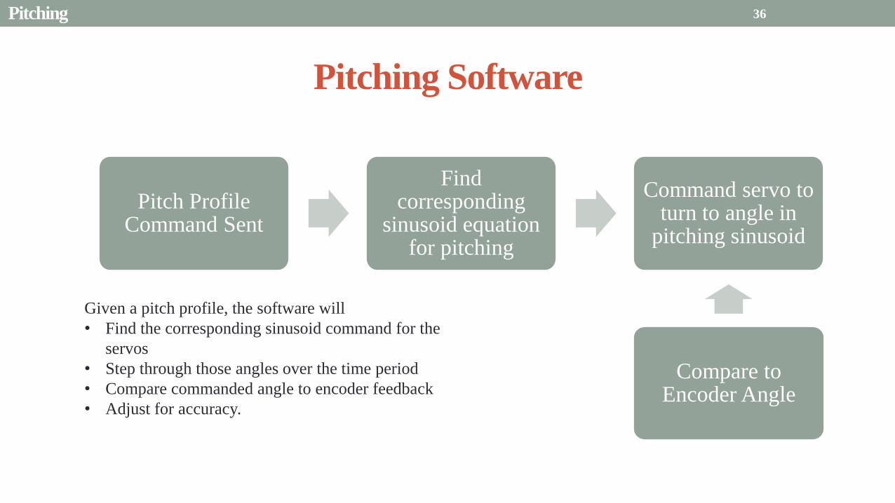

Presentation Sections
bull Purpose and Objectives
bull GHOST Design Solution
bull Critical Project Elements
bull Requirement Satisfaction
bull Controlled Deployment Rate
bull Pitching
bull Survive Launch
bull ElectronicSoftware Integration
bull Manufacturing the CubeSat
bull Summary
bull Remaining Risks
bull Verification and Validation of Design
bull Project Planning
37
Canisterized Satellite Dispenser CSD
bull 6U fits into CSD during launch
bull Gives extra clearance on each side bull Allows for locking mechanism outside the 6U
bull Available with Alum 6061
bull Pushed into orbit on ldquoTabrdquo structure bull Additional tabs added below CubeSat base
bull Able to separate tabs for each separate section
38 Survive Launch
Structural Integrity of Pitching Axle and Selection of
Material
bull Aluminum 6061
bull Lightweight (density of 27gcc)
bull Very strong
bull Inexpensive
bull Pitching Axle ndash rod 1 cm in diameter
bull If made of Aluminum 6061
bull Can withstand shear force of 162 kN (~3600 lbs)
bull Does not take into account ability of motor to withstand torque
F (from Solar
Sail)
τ
39 Survive Launch
Pitching Axle
Launch Locks
bull Sierra Nevada SP-5025 pin puller
bull 350 lbf (1500 N) of shear load
bull Powered by a single timed power pulse to one of
the redundant heater circuits
bull SP -5025 greatly exceeds budget so manual
screw and bolt sized appropriately simulate
launch locks in the prototype
40
SP-5025
SP-5025
Deployed
Stowed
Simulated
Launch Locks
Survive Launch
Credit to SNC
Secure Blade Tip Mass
bull C-brackets attached to exterior walls stabilize tip mass vertically and horizontally
bull Cylindrical tip mass fits securely in brackets on both sides
bull Holding torque of stepper motor and tape-measure material holds tip mass in towards rolled blade
bull Within outer limit required by CSD
41
16 cm
075 cm 2 cm
Survive Launch
Presentation Sections
bull Purpose and Objectives
bull GHOST Design Solution
bull Critical Project Elements
bull Requirement Satisfaction
bull Controlled Deployment Rate
bull Pitching
bull Survive Launch
bull ElectronicsSoftware Integration
bull Manufacturing the CubeSat
bull Summary
bull Remaining Risks
bull Verification and Validation of Design
bull Project Planning
42
Service Loop
Power and input wires needed in for stepper
motor in deployment module
bull 4 12A rated wires AWG 21 D = 073 mm
bull Full loop around pitching axle to allow for
plusmn90deg rotational freedom
bull 1 cm diameter hole through each plate
bull Current must run throughout launch to
keep holding torque
bull Need not worry about freezing later in mission
Wires (red) exit opening in wall loops around
pitching axle enters opening in opposite wall
43 ElectronicsSoftware Integration
Electrical Block Diagram
Micro-
controller
35 V Supply
Stepper
Driver
Stepper
Motor
H4
H5
H3
H6
Key IO
CCP
Power
Serial
GND
Sensor
VDD
M0
M1
ENABLE
CONFIG
GND
DIR
STEP
E0
E2
B2
B1
A1
A2
VMOT GND VDD
5 V Supply
GND
Servo
Driver 1
Servo 1 TX RX
P G A B C
5V GND U V W Servo
Driver 2
Servo 2
P G A B C
5V GND C2 C3 C4 U V W
Encoder
J2 J3 J4 J5 J6 J7
VDC G
C0
(Speed Set)
C0
(Speed Set)
RS 232
DAC
A B C
Encoder VDC G A B C
B5 B4
A3
A7
B7
B6
D4
D3
D4 D3
C2 C3 C4
VoutA
VoutB
SCLK CS
DIN
GND
Tin Rout Vin GND
VDD
A4
SLEEP
FAULT H0
E1
44 ElectronicsSoftware Integration
Microcontroller PIC18F87K22
Board Requirements
bull Serial output for communication with computer
and servomotor controller
bullDAC used for servomotor communication
bull I0 ports for stepper driver interface
bull CCP port for stepper driver interface
bull Header pins for the encoder interface
Total
18 IO
1 CCP
1 TXRX
bull Would need more IO and CCP ports for a second
stepper motor driver
bull Unused ports 37 IO and 10 CCPECCP
ElectronicsSoftware Integration
PCB Design
bull 2 Layer Board
bull FR4 material
bull 1 oz Copper traces
bull Estimated Dimension = 5times5 cm
bull (See Appendix for Electrical Schematic)
EasyPIC PRO
v7 Pinout
80 Pin Development
Board
ElectronicsSoftware Integration
Incompatible Industrial Boards
Presentation Sections
bull Purpose and Objectives
bull GHOST Design Solution
bull Critical Project Elements
bull Requirement Satisfaction
bull Controlled Deployment Rate
bull Pitching
bull Survive Launch
bull ElectronicsSoftware Integration
bull Manufacturing the CubeSat
bull Summary
bull Remaining Risks
bull Verification and Validation of Design
bull Project Planning
47
Manufacturing In-House vs Purchasing
48
Part In-House Purchase Details
CubeSat walls Aluminum will be purchased with correct thickness and
manufactured to needed dimensions
Blade and pitching axle Axles can be cut down to needed length
Corner brackets Brackets can be altered to fit needed dimensions
S-brackets and C-brackets Will have to be machined to fit strict dimensions
Tip mass Tip mass can be cut down to needed length
Tape-measure material Purchased from McMaster-Carr
Solar sail blade material Blade material is provided for free by NASA LaRC
Launch Locks Launch locks we will use are a screw and bolt
Launch Tabs for CSD Tabs must meet strict dimensions to fit into CSD from
Planetary Systems Corporation
Hub to attach pitching axle to blade module Will have to be machined to meet needed dimensions
Screwsnutsbolts All can be purchased in various sizes and lengths
Motorsencoders and motor drivers All purchased to meet necessary requirements
Electronics board Will have to be made to accommodate needed electronics
Stabilizers to hold pitching motors Will have to be machined to properly fit around motors
Manufacturing the CubeSat
Assembly Procedure
49 Manufacturing the CubeSat
Bonding Mylar to Spool and Stiff Material
bull Loctite Super Glue Professional
bull Shear strength of 01 Nmm2
bull Cross-Sectional Area = 6575 mm2
bull Shear Stress = 33e-4 Nmm2
bull Blade will retain 4 rolls around axle at
final length
bull Loctite to bond stainless steel stiff
material to Mylar and to spool
F = mg = 217 N
Motor
Blade frac14 of roll glued
50 Manufacturing the CubeSat
Fixing Deployment Motor to S-Bracket
51
bull Deployment stepper motor is attached to S-bracket
bull S-bracket stabilized to back of blade deployment
module and vertical CubeSat walls
bull Motor is capable of being screwed directly to S-bracket
bull S-bracket has thickness of 18 inch
Holes for screws to
stabilize S-bracket
Hole for motor shaft
or press-fit ball
bearing to attach to
blade axle
Holes to screw motor
to S-bracket
Manufacturing the CubeSat
Pitching Axle Interfaces
bull Pitching axle to motor axle
bull Motor axle (smaller) fits into pitching
axle (larger) using set-screws
bull Pitching Axle to Blade Reel
Module
bull Axle fixed by set screws inside a hub
52
Pitching Axle
Hub
Motor Axle
4 Set Screws
Manufacturing the CubeSat
Presentation Sections
bull Purpose and Objectives
bull GHOST design solution
bull Critical Project Elements
bull Requirement Satisfaction
bull Controlled Deployment Rate
bull Pitching
bull Survive Launch
bull ElectronicSoftware Integration
bull Manufacturing the CubeSat
bull Summary
bull Remaining Risks and Mitigations
bull Verification and Validation of Design
bull Schedule and remaining work
53
Requirements Satisfaction
Aspect Requirement GHOST Specification
Mass 1 kgU 288 kg
Volume lt= 12U 6U
Life Span 4 months Greater than 4 months
Space Applicable
While design does not need to be
space worthy it should be applicable
to being used in space
All components are picked for
realistic use in space with minimal
cost parts and increased life span
54 Summary
Requirements Satisfaction
Aspect Requirement GHOST Specification
Characteristic Acceleration ac ge 01 mms2 ac = 03868 mms2
Sail Aspect Ratio AR ge 1001 AR = 38931
Sail Deployment Speed 1 cms le 10cms ~5 cms
Pitching Range Ability to pitch blades plusmn 90deg Ability to pitch blades plusmn 90deg
Pitching Coordination Multiple blade coordination when
pitching
Can pitch both blades at once either to
same angle or opposite angles
55 Summary
Presentation Sections
bullPurpose and Objectives
bullGHOST Design Solution
bullCritical Project Elements
bullRequirement Satisfaction
bullRemaining Risks
bullVerification and Validation of Design
bullProject Planning
56
Design Risks
Severity
Likelihood Marginal Major
Often Pitch angle error root not
following tip
Occasional Power loss COMM loss
Structural survivability
pitching motor failure
Improbable Small tear in Mylar Deploy too fast stowage
and deployment of Mylar
Axle failure
launch fail
space dust
deployment motor failure
57 Remaining Risks
Logistical Risks
Severity
Likelihood Minor Marginal Major
Often Parts delayed due to US
Postal Service
Occasional Structural consultation
unavailable
Ball vibrations test is not
available machine parts
not done on schedule
Government shutdown and
we canrsquot get Mylar or help
from NASA
Improbable No time for pitching test
High Bay in Fleming is
unavailable motors donrsquot
show up
58 Remaining Risks
Financial Risks
Severity
Likelihood Minor Marginal Major
Often Repurchase parts
Occasional Motor breaks Price of shake table
Improbable Hyper inflation
59 Remaining Risks
Presentation Sections
bullPurpose and Objectives
bullGHOST Design Solution
bullCritical Project Elements
bullRequirement Satisfaction
bullRemaining Risks
bullVerification and Validation of Design
bullProject Planning
60
Deployment System
Validate that the blade is deployed at a constant rate of 1-10 cms in a high bay
room
Verify that the motor can deploy at constant rate
Verify with test that the deployment system does not use more than the maximum power available of 10W
Validate that the blade can successfully deploy a blade with tape measure
material at a constant rate along ground
Verify with demonstration that the tape measure material can extend length of
blade
Verification and Validation
Verification and Validation
61
Blade Deployment Testing Information
bull Location Prof Frewrsquos High Bay Lab
bull Scheduled MarchApril with late night access to avoid
scheduling conflicts
bull Measurement Tape measure for distance and video
camera for time
bull Power Delivered 6253A Dual DC Power Supply
delivers 0-20 V and 0-3A
Tape measure
marking
distance up
wall
Kinematic Model
bull Torque from motor drives a constant velocity deployment
120591119898119900119905119900119903 = 120591119903119900119897119897 + 120591119901119906119904ℎ119894119899119892 119879119872 minus 120591119892119903119886119907119894119905119910 119879119872
120591119903119900119897119897 =119889119868119903119900119897119897
119889119905120596119903119900119897119897 + 119868119903119900119897119897
119889120596119903119900119897119897
119889119905
120591119901119906119904ℎ119894119899119892 119879119872 =119889119898119890119909119905
119889119905119903119903119900119897119897119907 + 119898119890119909119905
119889119903119903119900119897119897
119889119905119907
120591119892119903119886119907119894119905119910 119879119872 = 119898119890119909119905119903119903119900119897119897119892 bull 120649119945119952119949119941119946119951119944 = 120782 120782120790120787 N∙m 120649119950119952119941119942119949119950119938119961 = 120782 120782120782120789 N∙m
Power Supply
Verification and Validation
CubeSat Wire
62
Pitching System
Validate that the blade reel modules experience coordinated pitching
Verify that one blade reel module experiences periodic
motion
Verify that the blade reel module rotates to 0deg upon
initialization
Verify that the blade pitches to a given command
angle
Verify that the motorencoder system does not exceed power
available
Verification and Validation
Verification and Validation
63
Verify Pitching Angle Experiment Equipment and Specs
bull Use R60D RVIT (Rotary Variable Inductance Transducer) sensor to measure angles attaches to pin (red) in line with pitching axis bull Measures ranges of plusmn60deg rotation
bull Input Voltage = plusmn15 V
bull Output Voltage = plusmn75 V
bull Resolution = 0125 Vdeg
bull 119891119898119886119909 = 20 Hz
bull Use AD524 Precision Amplifier Instrumentation for signal conditioning bull Input Voltage plusmn10 V
bull Output Voltage plusmn10V
bull Requires Supply Voltage plusmn15
bull Use NI 9201 bull Input Voltage plusmn10 V
bull Has a USB output that can connect to a computer where vi program records
Experiment Set-Up
R60D RVIT
AD524
NI 9201 PC via USB
Verification and Validation 64
Verify Periodic Motion Experiment
bull Using the R60D RVIT set-up to measure deflection angles
bull With data of the angle deflection 120579 angular velocity 120596 and angular acceleration 120572 can be measured bull Motor restriction 120591119898119886119909 = 032 Nmiddotm
bull Model restriction 120596119898119886119909 = Ω2 if Ω = 2rpm 120596119898119886119909 = 02094 rads
Validation Model
bull R60D RVIT measures plusmn60deg deflection angles bull Critical condition blade reel module pitches plusmn90deg Ω=2rpm
bull 120572119888 = 00172 rads2 and 120596119898 = 0164 rads thus 120591119898 = 0083 mNmiddotm (119868119898119900119889 = 00048 kgmiddotm2)
120579 119905 120596 119905 120572 119905
Verification and Validation 65
Verification and Validation
Structural System
Validate that the final design can survive launch by using a shake
table
Verify the structural integrity by demonstrating that all stationary parts are
static
Verification and Validation 66
Trade Study FEM vs Vibration Table
Cost Time Experience
Similar to
Actual
Launch
Guaranteed Can
Do Total
FEM 4 1 1 3 4 215
Vibration
Table 2 3 4 4 2 32
Weight () 5 30 25 20 20 100
67 Verification and Validation
See Appendix for Full Trade Study
Validate Structural Stability
bull Will use a shaker table from Ball Aerospace
bull Cost = $250hr
bull Schedule Time to be determined in April
bull Specifications Peak vibration occurs with 34g at
frequency of 16 Hz (Saturn V)
bull Will be verified by examining the structural integrity
of the manufacturing
Verification and Validation 68
CubeSat
Shake Table
Presentation Sections
bullPurpose and Objectives
bullGHOST Design Solution
bullCritical Project Elements
bullRequirement Satisfaction
bullRemaining Risks
bullVerification and Validation of Design
bullProject Planning
69
Organizational Chart
Mark
Dolezal
Emily
Proano
Lauren
Persons
Casey
Myers
Nicholas
Busbey
Taylor
Smith
Karynna
Tuan
Megan
Scheele
Project
Manager
Software
Lead
Electrical
Lead
Systems Test and
Safety
Manufacturing
Lead Mechanics
Lead
CFO and
Materials
Lead
Organizing
team
meetings
Supporting
other leads
Non CPE
Tasks
Deployment
Control
Pitching
Control Motors and
Electronics
Power
Integrate
all system Perform
and Plan
tests
Manufacture
all in-house
parts
SolidWorks
Keep track
of financial
spending
Right
materials
are being
utilized
CubeSat
Assembly
Specific
System
Requirements
70 Project Planning
GHOST
Materials Mechanical Electrical Software Documents
Shake Table
Vibration
Analysis
Mechanical
Layout
Power Budget Pitch Control
Algorithm
Deployment
Rate Control
Algorithm SolidWorks
Model
Electrical
Wiring Layout
Thermodynamic
Analysis of
Electronic System
Mass Budget
Prototype of
CubeSat Bus
Motor
Subsystem
CDR
FFR
Spring
Schedule
Financial
Budget
Work Breakdown Structure (WBS)
Mylar from
NASA
Spin Up
Algorithm
Emergency
StopRestart System
71 Project Planning
PCB Design
Spring
Documents
113 120 127 203 210 217 224 303 310 317 324 331 407 414 421 428
MSR TRR SFR PFR
Time (date)
Purchase
motorsdrivers
Preliminary code
Electronic
integration
Test code
Electronicscode
interface
Purchase
raw materials
Manufacture frame
Assemble bus
Manufacture
remaining parts
Integrate system
Deployment test
Pitching test
Vibration test
Ta
sks
72
GHOST Spring Schedule
Project Planning
Planned Uncertainty
Key
Test Plan Test Scheduled Facility Specialized Equipment
Verify Pitch Angle 317 ITLL R60D RVIT NI 9201 AD524 Oscilloscope bench
power source
Zero Pitch Angle 317 ITLL R60D RVIT NI 9201 AD524 Oscilloscope bench
power source
Measure power used in
pitchdeployment 317 ITLL Ammeter voltmeter bench power source
Verify constant deployment 324 ITLL Firewire camera bench power source
ASEN2003BallTrackervi
Verify periodic motion 324 ITLL R60D RVIT NI 9201 AD524 Oscilloscope bench
power source
Validate tape measure ground
deployment 331 ITLL
Bench power source tape measure stop watch rollers
for tip mass
Validate coordinated pitching 331 ITLL R60D RVIT NI 9201 AD524 oscilloscope bench
power source
Validate 1g blade deployment 331-414 Prof Frew
high bay
Portable 6253A Dual DC Power Supply ladder tape
measure video camera
Validate launch ready 414 Ball Aero Shake Table
Project Planning 73
Cost Table ndash Structural Components
Part Price per
part NeededVolume Needed Total Price Supplier
Aluminum 6061 Sheet
(18rdquo thick) $ 8976 2ft times 2ft times 18 in $ 8976 The Metals Depot
Aluminum 6061 rod
(14 in diameter) $280 2 ft $280 The Metals Depot
Aluminum6061 rod
(716 in diameter) $494 2 ft $494 The Metals Depot
Steel Corner Brackets
(34rdquo times 12rdquo)
$197 4
braces 16 $788 Home Depot
Hardened 302 Stainless
Steel $3300 2 cm times 5 m times 127 microm $3300 McMaster-Carr
Total $11834
74 Project Planning
Cost Table ndash Electrical Components
Part Price per
part Needed Total Price Supplier
Sanyo Stepper Motor $ 5995 2 $11990 Pololu Electronics and Robotics
DRV8834 Low-Voltage Stepper
Motor Driver $995 2 $1990 Pololu Electronics and Robotics
FAULHABER 2036 BLDC
Servo Motor $23000 2 $46000 MicroMo Micro Motion Solutions
Atmel ATA6832-DK Brushless
DC Motor Controller $20800 2 $41600 Atmel
Encoder AU-ZSD1000A $22500 2 $45000 MicroMo Micro Motion Solutions
PIC18F87K22 Microcontroller $500 1 $500 Microchip
AD-524 Signal Converter $1767 1 $1767 Agilent
Total $148847
75 Project Planning
Questions
76
References
bull wwwloctiteproductscom
bull Vallado D A Fundamentals of Astrodynamics and Applications
bull Guerrant D Lawrence D Heaton A Earth Escape Capabilities of the Heliogyro Sail AIAA Paper
bull wwwspaceflightnowcom
bull Guerrant D HGVizGuim MATLAB Program
bull httpwwwmicromocombrushless-dc-motorsaspx
bull httpwwwfaulhabercomservletcomitmrwawservletAnzeigefremdaufruf=jaampkdid=40929ampsprachid=1amphtdigurl=n169933i95222html
bull httpwwwpololucom
bull httpasmmatwebcomsearchSpecificMaterialaspbassnum=MA6061t6
bull httpwwwruagcomthermalSpace_Thermal_HardwareMulti_Layer_Insulation
bull Helgesen Bryan Sierra Nevada Corporation
77
GyroSail Launch Configuration and Deployment Sequence
78
1 Launch configuration (6U) 2 Blade reel modules pitch to zero Fits within a 6U or 12U dispenser
3 PV arrays deploy
Other array configurations are possible
williamkwilkienasagov NASA PREDECISIONAL - FOR DISCUSSION PURPOSES ONLY
78 Appendix
GyroSail Primary Bus Systems Based on modified JPLU MichUCLACal PolyUT INSPIRE bus
williamkwilkienasagov
05U cold gas thruster ACS for detumbling
and initial spin-up
(httpwwwaustinsatnet)
05U EPS battery CampDH UHF backup
comms (U Mich) 05U DSN-compatible X-band
communications (JPL)
05U COTS star trackerimager ADC (BCT) sail
module processor (CU)
Klesh A et al 2013 ldquoINSPIRE Interplanetary NanoSpacecraft Pathfinder In Relevant Environmentrdquo Proceedings of the AIAAUSU Conference on Small Satellites Around the Corner SSC13-
XI-8 httpdigitalcommonsusuedusmallsat2013all2013127
NASA PREDECISIONAL - FOR DISCUSSION PURPOSES ONLY
79 Appendix
COMM Subsystem
bull 18 m Ka-band antennas at White
Sands New Mexico
bull Goddard Space Flight Center
Greebelt Maryland USA
supplied the Mulemba Space
Center in Angola
80 Appendix
Orion Crew
Module
6U Canisterized Satellite
Dispenser (CSD) ESPA Ring
Spacecraft
Adapter
Interim Cryogenic Propulsion
Stage (ICPS)
Secondary Payload Attachment to SLS
The SLS design is currently going through CDR An ESPA
ring is not currently in place but is mentioned in the SLS
CONOPS in order to accommodate secondary payloads
81 Appendix
Max Thrust Condition Collective 90deg pitch profile
Max thrust normal to orbital plane
(Halo orbits orbital plane rotation ie
inclination change)
82
Credit to Dan Guerrant
Appendix
Max Thrust Condition
F vs β M vs β
83
Credit to Dan Guerrant
Appendix
No Thrust Condition Collective 0deg pitch profile
Zero thrust
84
Credit to Dan Guerrant
Appendix
No Thrust Condition
F vs β M vs β
85
Credit to Dan Guerrant
Appendix
Max Torque Condition Collective 35deg pitch profile
Max torque used for spinning up sc
(opposite orientation for despinning)
86
Credit to Dan Guerrant
Appendix
Max Torque Condition
F vs β M vs β
87
Credit to Dan Guerrant
Appendix
Max In-Plane Thrust Condition Cyclic 35deg pitch profile
Max thrust in in-plane (d2) direction for orbit raising
88
Credit to Dan Guerrant
Appendix
Max In-Plane Thrust Condition
F vs β M vs β
89
Credit to Dan Guerrant
Appendix
Orbit Raising
F
90 Appendix
Thermal Space Concerns
bull Material Concerns
bull Aluminum 6061 -196 degC to 160deg C
bull Electronics Concerns
bull Typical Operating Temperature -55 to 80 degC
bull Countermeasures
bull Multi-layer Insulation AAErotherm S10-190
bull (0005 ndash 0035 Wm2K)
bull Battery operated heaters for pre-sail deployment
Multi-layer Insulation
Layer 1 1 x Outer layer
Layer 2 8 x 03 mil VDAPolyimideVDA perf
8 x Woven Polyester netting
Layer 3 1 x Outer layer
Layer 4 1 x Woven Polyester netting
91 Appendix
Rolled Up Blade Reel Calculation Optimal Sail Length 545 m ndash Sail chord of 14 cm
Max Diameter of Spool 598 cm
Diameter of Axle 05 cm
Length of Stiff Material 5 m
Dimension of Stiff Material 5 m times 2 cm times 127 microm
92 Appendix
Torque calculation
bull Note current calculated via T=kI (where T is torque I is amp k is the torque
constant specific to the motor)
T = kI
(k = 005 NmA)
93 Appendix
Servo Controller
94 Appendix
Encoder Dimensions and Interface
bull FAULHABER IE2-1024
95 Appendix
Stepper Motor Torque
96 Appendix
Motor Phases (Stepper)
97 Appendix
98 Appendix
99 Appendix
100 Appendix
101 Appendix
Microcontroller
102 Appendix
ATA6832 Phase Output Chip
103 Appendix
ATA6624 Bypassed Chip
bull Bypassed chip
on servo controller
104 Appendix
Power Budget
105 Appendix
Wire Gauge
bull Stepper Motor 26AWG (04 mm diameter)
bull Servomotor 24 AWG (051 mm diameter)
bull Encoder 24 AWG
Voltage Drop () AWG Max Gauge
001 5
01 15
1 25
5 32
NOTE Voltage drop calculated at 1A and 40 cm of wire
106
24 AWG Wire
Appendix
Trade Study ndash FEM vs Vibration Table
Factor 4 3 2 1
Cost No money 0 gt C gt $100 $100 gt C gt $300 $300 lt C
Time 0 min lt T lt 30 min 30 min lt T lt 2 hrs 2 hrs lt T lt 1 day 1day lt T
Experience Everyone has
experience
A couple people
know how to
1 person has
experience
No one has
experience
Similar To Actual
Launch Simulate real launch
Doesnrsquot have all
variables experienced
Has only a couple
similarities
No similarities to
launch
Guaranteed Can Do
Donrsquot need any
outside equipment or
help
Need outside
equipment but
guaranteed use
Need outside
equipment but own
work at higher
priority
Need outside
equipment but canrsquot
use
Scoring
107 Appendix
Weighting
Weight () Category Reasoning
5 Cost Have a lot of extra $ in the budget
30 Time Have a strict schedule but not a main focus of the
project
25 Experience If no one has experience it will take a lot of time
20 Similar to Actual Launch Needs to be like actual launch
20 Guaranteed Can Do Needs to be able to accomplish but not the most
important focus
108 Appendix
Finite Element Method (FEM)
Objectives Description ProCon
Cost No money because one of us
would do it Pro
Time A lot of time to learn and then
perform FEM Con
Experience No one in group has FEM
experience Con
Similar to Actual Launch Very similar to actual launch Pro
Guaranteed Can Do All we need is paper pen and
theory to do Pro
109 Appendix
Vibration Table
Objective Description ProCons
Cost $250hr Con
Time A hour on the table should simulate
launch Pro
Experience Donrsquot need experience to run
vibration table Pro
Similar to Actual Launch Actually putting our system through
vibration stress Pro
Guaranteed Can Do No guarantee but most likely can Con
110 Appendix
SpinUp State
1 Check value of SpinUp to see if satellite is already spun up
bull Continue if satellite is not already spun-up
2 Deploy the tape stiffened length of the blade
3 Pitch to the spin up angle
4 Wait until characteristic angular velocity is reached
5 Pitch to pre-deployment position
6 Save SpinUp as completed
Appendix 111
Deployment State
1 Check if satellite has been spun up yet
bull Continue if it has
2 Check if blades are already deployed
bull Continue if they havenrsquot
3 Run deploy algorithm until blades are fully deployed
4 Save value saying blades have been deployed
Appendix 112
Pitching State
1 Check if satellite has been spun up
bull Continue if satellite has been spun up
2 Check if blades have been deployed
bull Continue if blades have been deployed
3 Look at commanded pitch profile
4 Find correlated sinusoid command
5 Command servo to pitch angle for the time in the orbit
6 Continue until given a new pitch command
Appendix 113
Emergency Stop
1 Save which state was interrupted
2 Save last position in interrupted
state
3 Wait until Restart command is
received
1 Check two previous states to see
what is being restarted
2 Look at saved last position in
state being restarted
3 Adapt the algorithm of the state
to continue where left off
Restart
Appendix 114
Comparison with Previous Heliogyro Concepts MIT (1989) NASA (2011) GHOST
Total sail craft mass (kg) 18 84
288 (6)
Characteristic acceleration ac
(mms2) 06 10 03868 (01854)
Sail reflective area (m2) 1200 960 1526
Non-sail mass (kg) 5 5 --
Number of sail blades 8 6 2
Blade chord (m) 15 08 014
Blade length (m) 100 200 545
Rotational period (minutes) 3 3 1
Blade root stress (Pa) 8650 34000 --
Blade root allowable stress (Pa) 55 M 55 M --
Blade root tension load (N) 01 007 --
115 Appendix
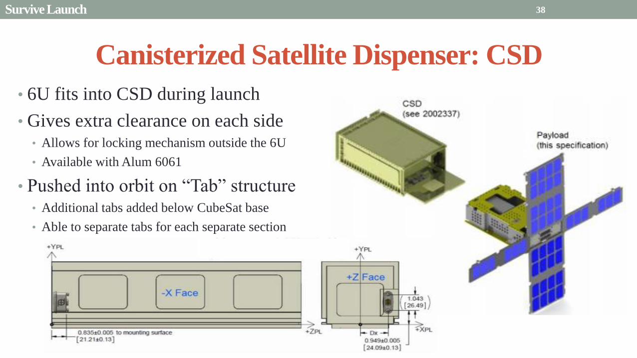
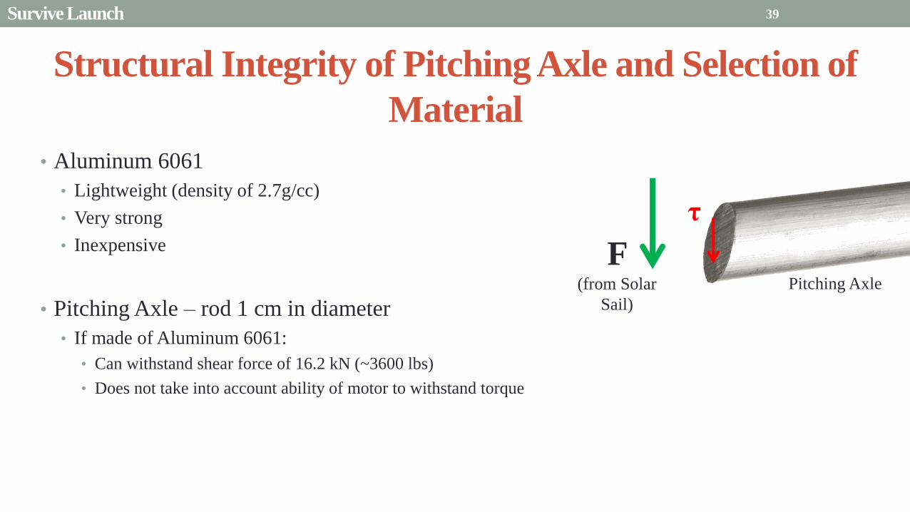
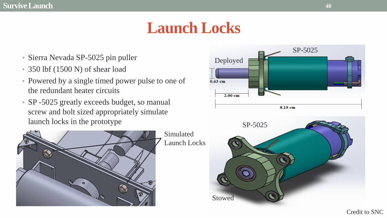
Launch Locks
bull Sierra Nevada SP-5025 pin puller
bull 350 lbf (1500 N) of shear load
bull Powered by a single timed power pulse to one of
the redundant heater circuits
bull SP -5025 greatly exceeds budget so manual
screw and bolt sized appropriately simulate
launch locks in the prototype
40
SP-5025
SP-5025
Deployed
Stowed
Simulated
Launch Locks
Survive Launch
Credit to SNC
Secure Blade Tip Mass
bull C-brackets attached to exterior walls stabilize tip mass vertically and horizontally
bull Cylindrical tip mass fits securely in brackets on both sides
bull Holding torque of stepper motor and tape-measure material holds tip mass in towards rolled blade
bull Within outer limit required by CSD
41
16 cm
075 cm 2 cm
Survive Launch
Presentation Sections
bull Purpose and Objectives
bull GHOST Design Solution
bull Critical Project Elements
bull Requirement Satisfaction
bull Controlled Deployment Rate
bull Pitching
bull Survive Launch
bull ElectronicsSoftware Integration
bull Manufacturing the CubeSat
bull Summary
bull Remaining Risks
bull Verification and Validation of Design
bull Project Planning
42
Service Loop
Power and input wires needed in for stepper
motor in deployment module
bull 4 12A rated wires AWG 21 D = 073 mm
bull Full loop around pitching axle to allow for
plusmn90deg rotational freedom
bull 1 cm diameter hole through each plate
bull Current must run throughout launch to
keep holding torque
bull Need not worry about freezing later in mission
Wires (red) exit opening in wall loops around
pitching axle enters opening in opposite wall
43 ElectronicsSoftware Integration
Electrical Block Diagram
Micro-
controller
35 V Supply
Stepper
Driver
Stepper
Motor
H4
H5
H3
H6
Key IO
CCP
Power
Serial
GND
Sensor
VDD
M0
M1
ENABLE
CONFIG
GND
DIR
STEP
E0
E2
B2
B1
A1
A2
VMOT GND VDD
5 V Supply
GND
Servo
Driver 1
Servo 1 TX RX
P G A B C
5V GND U V W Servo
Driver 2
Servo 2
P G A B C
5V GND C2 C3 C4 U V W
Encoder
J2 J3 J4 J5 J6 J7
VDC G
C0
(Speed Set)
C0
(Speed Set)
RS 232
DAC
A B C
Encoder VDC G A B C
B5 B4
A3
A7
B7
B6
D4
D3
D4 D3
C2 C3 C4
VoutA
VoutB
SCLK CS
DIN
GND
Tin Rout Vin GND
VDD
A4
SLEEP
FAULT H0
E1
44 ElectronicsSoftware Integration
Microcontroller PIC18F87K22
Board Requirements
bull Serial output for communication with computer
and servomotor controller
bullDAC used for servomotor communication
bull I0 ports for stepper driver interface
bull CCP port for stepper driver interface
bull Header pins for the encoder interface
Total
18 IO
1 CCP
1 TXRX
bull Would need more IO and CCP ports for a second
stepper motor driver
bull Unused ports 37 IO and 10 CCPECCP
ElectronicsSoftware Integration
PCB Design
bull 2 Layer Board
bull FR4 material
bull 1 oz Copper traces
bull Estimated Dimension = 5times5 cm
bull (See Appendix for Electrical Schematic)
EasyPIC PRO
v7 Pinout
80 Pin Development
Board
ElectronicsSoftware Integration
Incompatible Industrial Boards
Presentation Sections
bull Purpose and Objectives
bull GHOST Design Solution
bull Critical Project Elements
bull Requirement Satisfaction
bull Controlled Deployment Rate
bull Pitching
bull Survive Launch
bull ElectronicsSoftware Integration
bull Manufacturing the CubeSat
bull Summary
bull Remaining Risks
bull Verification and Validation of Design
bull Project Planning
47
Manufacturing In-House vs Purchasing
48
Part In-House Purchase Details
CubeSat walls Aluminum will be purchased with correct thickness and
manufactured to needed dimensions
Blade and pitching axle Axles can be cut down to needed length
Corner brackets Brackets can be altered to fit needed dimensions
S-brackets and C-brackets Will have to be machined to fit strict dimensions
Tip mass Tip mass can be cut down to needed length
Tape-measure material Purchased from McMaster-Carr
Solar sail blade material Blade material is provided for free by NASA LaRC
Launch Locks Launch locks we will use are a screw and bolt
Launch Tabs for CSD Tabs must meet strict dimensions to fit into CSD from
Planetary Systems Corporation
Hub to attach pitching axle to blade module Will have to be machined to meet needed dimensions
Screwsnutsbolts All can be purchased in various sizes and lengths
Motorsencoders and motor drivers All purchased to meet necessary requirements
Electronics board Will have to be made to accommodate needed electronics
Stabilizers to hold pitching motors Will have to be machined to properly fit around motors
Manufacturing the CubeSat
Assembly Procedure
49 Manufacturing the CubeSat
Bonding Mylar to Spool and Stiff Material
bull Loctite Super Glue Professional
bull Shear strength of 01 Nmm2
bull Cross-Sectional Area = 6575 mm2
bull Shear Stress = 33e-4 Nmm2
bull Blade will retain 4 rolls around axle at
final length
bull Loctite to bond stainless steel stiff
material to Mylar and to spool
F = mg = 217 N
Motor
Blade frac14 of roll glued
50 Manufacturing the CubeSat
Fixing Deployment Motor to S-Bracket
51
bull Deployment stepper motor is attached to S-bracket
bull S-bracket stabilized to back of blade deployment
module and vertical CubeSat walls
bull Motor is capable of being screwed directly to S-bracket
bull S-bracket has thickness of 18 inch
Holes for screws to
stabilize S-bracket
Hole for motor shaft
or press-fit ball
bearing to attach to
blade axle
Holes to screw motor
to S-bracket
Manufacturing the CubeSat
Pitching Axle Interfaces
bull Pitching axle to motor axle
bull Motor axle (smaller) fits into pitching
axle (larger) using set-screws
bull Pitching Axle to Blade Reel
Module
bull Axle fixed by set screws inside a hub
52
Pitching Axle
Hub
Motor Axle
4 Set Screws
Manufacturing the CubeSat
Presentation Sections
bull Purpose and Objectives
bull GHOST design solution
bull Critical Project Elements
bull Requirement Satisfaction
bull Controlled Deployment Rate
bull Pitching
bull Survive Launch
bull ElectronicSoftware Integration
bull Manufacturing the CubeSat
bull Summary
bull Remaining Risks and Mitigations
bull Verification and Validation of Design
bull Schedule and remaining work
53
Requirements Satisfaction
Aspect Requirement GHOST Specification
Mass 1 kgU 288 kg
Volume lt= 12U 6U
Life Span 4 months Greater than 4 months
Space Applicable
While design does not need to be
space worthy it should be applicable
to being used in space
All components are picked for
realistic use in space with minimal
cost parts and increased life span
54 Summary
Requirements Satisfaction
Aspect Requirement GHOST Specification
Characteristic Acceleration ac ge 01 mms2 ac = 03868 mms2
Sail Aspect Ratio AR ge 1001 AR = 38931
Sail Deployment Speed 1 cms le 10cms ~5 cms
Pitching Range Ability to pitch blades plusmn 90deg Ability to pitch blades plusmn 90deg
Pitching Coordination Multiple blade coordination when
pitching
Can pitch both blades at once either to
same angle or opposite angles
55 Summary
Presentation Sections
bullPurpose and Objectives
bullGHOST Design Solution
bullCritical Project Elements
bullRequirement Satisfaction
bullRemaining Risks
bullVerification and Validation of Design
bullProject Planning
56
Design Risks
Severity
Likelihood Marginal Major
Often Pitch angle error root not
following tip
Occasional Power loss COMM loss
Structural survivability
pitching motor failure
Improbable Small tear in Mylar Deploy too fast stowage
and deployment of Mylar
Axle failure
launch fail
space dust
deployment motor failure
57 Remaining Risks
Logistical Risks
Severity
Likelihood Minor Marginal Major
Often Parts delayed due to US
Postal Service
Occasional Structural consultation
unavailable
Ball vibrations test is not
available machine parts
not done on schedule
Government shutdown and
we canrsquot get Mylar or help
from NASA
Improbable No time for pitching test
High Bay in Fleming is
unavailable motors donrsquot
show up
58 Remaining Risks
Financial Risks
Severity
Likelihood Minor Marginal Major
Often Repurchase parts
Occasional Motor breaks Price of shake table
Improbable Hyper inflation
59 Remaining Risks
Presentation Sections
bullPurpose and Objectives
bullGHOST Design Solution
bullCritical Project Elements
bullRequirement Satisfaction
bullRemaining Risks
bullVerification and Validation of Design
bullProject Planning
60
Deployment System
Validate that the blade is deployed at a constant rate of 1-10 cms in a high bay
room
Verify that the motor can deploy at constant rate
Verify with test that the deployment system does not use more than the maximum power available of 10W
Validate that the blade can successfully deploy a blade with tape measure
material at a constant rate along ground
Verify with demonstration that the tape measure material can extend length of
blade
Verification and Validation
Verification and Validation
61
Blade Deployment Testing Information
bull Location Prof Frewrsquos High Bay Lab
bull Scheduled MarchApril with late night access to avoid
scheduling conflicts
bull Measurement Tape measure for distance and video
camera for time
bull Power Delivered 6253A Dual DC Power Supply
delivers 0-20 V and 0-3A
Tape measure
marking
distance up
wall
Kinematic Model
bull Torque from motor drives a constant velocity deployment
120591119898119900119905119900119903 = 120591119903119900119897119897 + 120591119901119906119904ℎ119894119899119892 119879119872 minus 120591119892119903119886119907119894119905119910 119879119872
120591119903119900119897119897 =119889119868119903119900119897119897
119889119905120596119903119900119897119897 + 119868119903119900119897119897
119889120596119903119900119897119897
119889119905
120591119901119906119904ℎ119894119899119892 119879119872 =119889119898119890119909119905
119889119905119903119903119900119897119897119907 + 119898119890119909119905
119889119903119903119900119897119897
119889119905119907
120591119892119903119886119907119894119905119910 119879119872 = 119898119890119909119905119903119903119900119897119897119892 bull 120649119945119952119949119941119946119951119944 = 120782 120782120790120787 N∙m 120649119950119952119941119942119949119950119938119961 = 120782 120782120782120789 N∙m
Power Supply
Verification and Validation
CubeSat Wire
62
Pitching System
Validate that the blade reel modules experience coordinated pitching
Verify that one blade reel module experiences periodic
motion
Verify that the blade reel module rotates to 0deg upon
initialization
Verify that the blade pitches to a given command
angle
Verify that the motorencoder system does not exceed power
available
Verification and Validation
Verification and Validation
63
Verify Pitching Angle Experiment Equipment and Specs
bull Use R60D RVIT (Rotary Variable Inductance Transducer) sensor to measure angles attaches to pin (red) in line with pitching axis bull Measures ranges of plusmn60deg rotation
bull Input Voltage = plusmn15 V
bull Output Voltage = plusmn75 V
bull Resolution = 0125 Vdeg
bull 119891119898119886119909 = 20 Hz
bull Use AD524 Precision Amplifier Instrumentation for signal conditioning bull Input Voltage plusmn10 V
bull Output Voltage plusmn10V
bull Requires Supply Voltage plusmn15
bull Use NI 9201 bull Input Voltage plusmn10 V
bull Has a USB output that can connect to a computer where vi program records
Experiment Set-Up
R60D RVIT
AD524
NI 9201 PC via USB
Verification and Validation 64
Verify Periodic Motion Experiment
bull Using the R60D RVIT set-up to measure deflection angles
bull With data of the angle deflection 120579 angular velocity 120596 and angular acceleration 120572 can be measured bull Motor restriction 120591119898119886119909 = 032 Nmiddotm
bull Model restriction 120596119898119886119909 = Ω2 if Ω = 2rpm 120596119898119886119909 = 02094 rads
Validation Model
bull R60D RVIT measures plusmn60deg deflection angles bull Critical condition blade reel module pitches plusmn90deg Ω=2rpm
bull 120572119888 = 00172 rads2 and 120596119898 = 0164 rads thus 120591119898 = 0083 mNmiddotm (119868119898119900119889 = 00048 kgmiddotm2)
120579 119905 120596 119905 120572 119905
Verification and Validation 65
Verification and Validation
Structural System
Validate that the final design can survive launch by using a shake
table
Verify the structural integrity by demonstrating that all stationary parts are
static
Verification and Validation 66
Trade Study FEM vs Vibration Table
Cost Time Experience
Similar to
Actual
Launch
Guaranteed Can
Do Total
FEM 4 1 1 3 4 215
Vibration
Table 2 3 4 4 2 32
Weight () 5 30 25 20 20 100
67 Verification and Validation
See Appendix for Full Trade Study
Validate Structural Stability
bull Will use a shaker table from Ball Aerospace
bull Cost = $250hr
bull Schedule Time to be determined in April
bull Specifications Peak vibration occurs with 34g at
frequency of 16 Hz (Saturn V)
bull Will be verified by examining the structural integrity
of the manufacturing
Verification and Validation 68
CubeSat
Shake Table
Presentation Sections
bullPurpose and Objectives
bullGHOST Design Solution
bullCritical Project Elements
bullRequirement Satisfaction
bullRemaining Risks
bullVerification and Validation of Design
bullProject Planning
69
Organizational Chart
Mark
Dolezal
Emily
Proano
Lauren
Persons
Casey
Myers
Nicholas
Busbey
Taylor
Smith
Karynna
Tuan
Megan
Scheele
Project
Manager
Software
Lead
Electrical
Lead
Systems Test and
Safety
Manufacturing
Lead Mechanics
Lead
CFO and
Materials
Lead
Organizing
team
meetings
Supporting
other leads
Non CPE
Tasks
Deployment
Control
Pitching
Control Motors and
Electronics
Power
Integrate
all system Perform
and Plan
tests
Manufacture
all in-house
parts
SolidWorks
Keep track
of financial
spending
Right
materials
are being
utilized
CubeSat
Assembly
Specific
System
Requirements
70 Project Planning
GHOST
Materials Mechanical Electrical Software Documents
Shake Table
Vibration
Analysis
Mechanical
Layout
Power Budget Pitch Control
Algorithm
Deployment
Rate Control
Algorithm SolidWorks
Model
Electrical
Wiring Layout
Thermodynamic
Analysis of
Electronic System
Mass Budget
Prototype of
CubeSat Bus
Motor
Subsystem
CDR
FFR
Spring
Schedule
Financial
Budget
Work Breakdown Structure (WBS)
Mylar from
NASA
Spin Up
Algorithm
Emergency
StopRestart System
71 Project Planning
PCB Design
Spring
Documents
113 120 127 203 210 217 224 303 310 317 324 331 407 414 421 428
MSR TRR SFR PFR
Time (date)
Purchase
motorsdrivers
Preliminary code
Electronic
integration
Test code
Electronicscode
interface
Purchase
raw materials
Manufacture frame
Assemble bus
Manufacture
remaining parts
Integrate system
Deployment test
Pitching test
Vibration test
Ta
sks
72
GHOST Spring Schedule
Project Planning
Planned Uncertainty
Key
Test Plan Test Scheduled Facility Specialized Equipment
Verify Pitch Angle 317 ITLL R60D RVIT NI 9201 AD524 Oscilloscope bench
power source
Zero Pitch Angle 317 ITLL R60D RVIT NI 9201 AD524 Oscilloscope bench
power source
Measure power used in
pitchdeployment 317 ITLL Ammeter voltmeter bench power source
Verify constant deployment 324 ITLL Firewire camera bench power source
ASEN2003BallTrackervi
Verify periodic motion 324 ITLL R60D RVIT NI 9201 AD524 Oscilloscope bench
power source
Validate tape measure ground
deployment 331 ITLL
Bench power source tape measure stop watch rollers
for tip mass
Validate coordinated pitching 331 ITLL R60D RVIT NI 9201 AD524 oscilloscope bench
power source
Validate 1g blade deployment 331-414 Prof Frew
high bay
Portable 6253A Dual DC Power Supply ladder tape
measure video camera
Validate launch ready 414 Ball Aero Shake Table
Project Planning 73
Cost Table ndash Structural Components
Part Price per
part NeededVolume Needed Total Price Supplier
Aluminum 6061 Sheet
(18rdquo thick) $ 8976 2ft times 2ft times 18 in $ 8976 The Metals Depot
Aluminum 6061 rod
(14 in diameter) $280 2 ft $280 The Metals Depot
Aluminum6061 rod
(716 in diameter) $494 2 ft $494 The Metals Depot
Steel Corner Brackets
(34rdquo times 12rdquo)
$197 4
braces 16 $788 Home Depot
Hardened 302 Stainless
Steel $3300 2 cm times 5 m times 127 microm $3300 McMaster-Carr
Total $11834
74 Project Planning
Cost Table ndash Electrical Components
Part Price per
part Needed Total Price Supplier
Sanyo Stepper Motor $ 5995 2 $11990 Pololu Electronics and Robotics
DRV8834 Low-Voltage Stepper
Motor Driver $995 2 $1990 Pololu Electronics and Robotics
FAULHABER 2036 BLDC
Servo Motor $23000 2 $46000 MicroMo Micro Motion Solutions
Atmel ATA6832-DK Brushless
DC Motor Controller $20800 2 $41600 Atmel
Encoder AU-ZSD1000A $22500 2 $45000 MicroMo Micro Motion Solutions
PIC18F87K22 Microcontroller $500 1 $500 Microchip
AD-524 Signal Converter $1767 1 $1767 Agilent
Total $148847
75 Project Planning
Questions
76
References
bull wwwloctiteproductscom
bull Vallado D A Fundamentals of Astrodynamics and Applications
bull Guerrant D Lawrence D Heaton A Earth Escape Capabilities of the Heliogyro Sail AIAA Paper
bull wwwspaceflightnowcom
bull Guerrant D HGVizGuim MATLAB Program
bull httpwwwmicromocombrushless-dc-motorsaspx
bull httpwwwfaulhabercomservletcomitmrwawservletAnzeigefremdaufruf=jaampkdid=40929ampsprachid=1amphtdigurl=n169933i95222html
bull httpwwwpololucom
bull httpasmmatwebcomsearchSpecificMaterialaspbassnum=MA6061t6
bull httpwwwruagcomthermalSpace_Thermal_HardwareMulti_Layer_Insulation
bull Helgesen Bryan Sierra Nevada Corporation
77
GyroSail Launch Configuration and Deployment Sequence
78
1 Launch configuration (6U) 2 Blade reel modules pitch to zero Fits within a 6U or 12U dispenser
3 PV arrays deploy
Other array configurations are possible
williamkwilkienasagov NASA PREDECISIONAL - FOR DISCUSSION PURPOSES ONLY
78 Appendix
GyroSail Primary Bus Systems Based on modified JPLU MichUCLACal PolyUT INSPIRE bus
williamkwilkienasagov
05U cold gas thruster ACS for detumbling
and initial spin-up
(httpwwwaustinsatnet)
05U EPS battery CampDH UHF backup
comms (U Mich) 05U DSN-compatible X-band
communications (JPL)
05U COTS star trackerimager ADC (BCT) sail
module processor (CU)
Klesh A et al 2013 ldquoINSPIRE Interplanetary NanoSpacecraft Pathfinder In Relevant Environmentrdquo Proceedings of the AIAAUSU Conference on Small Satellites Around the Corner SSC13-
XI-8 httpdigitalcommonsusuedusmallsat2013all2013127
NASA PREDECISIONAL - FOR DISCUSSION PURPOSES ONLY
79 Appendix
COMM Subsystem
bull 18 m Ka-band antennas at White
Sands New Mexico
bull Goddard Space Flight Center
Greebelt Maryland USA
supplied the Mulemba Space
Center in Angola
80 Appendix
Orion Crew
Module
6U Canisterized Satellite
Dispenser (CSD) ESPA Ring
Spacecraft
Adapter
Interim Cryogenic Propulsion
Stage (ICPS)
Secondary Payload Attachment to SLS
The SLS design is currently going through CDR An ESPA
ring is not currently in place but is mentioned in the SLS
CONOPS in order to accommodate secondary payloads
81 Appendix
Max Thrust Condition Collective 90deg pitch profile
Max thrust normal to orbital plane
(Halo orbits orbital plane rotation ie
inclination change)
82
Credit to Dan Guerrant
Appendix
Max Thrust Condition
F vs β M vs β
83
Credit to Dan Guerrant
Appendix
No Thrust Condition Collective 0deg pitch profile
Zero thrust
84
Credit to Dan Guerrant
Appendix
No Thrust Condition
F vs β M vs β
85
Credit to Dan Guerrant
Appendix
Max Torque Condition Collective 35deg pitch profile
Max torque used for spinning up sc
(opposite orientation for despinning)
86
Credit to Dan Guerrant
Appendix
Max Torque Condition
F vs β M vs β
87
Credit to Dan Guerrant
Appendix
Max In-Plane Thrust Condition Cyclic 35deg pitch profile
Max thrust in in-plane (d2) direction for orbit raising
88
Credit to Dan Guerrant
Appendix
Max In-Plane Thrust Condition
F vs β M vs β
89
Credit to Dan Guerrant
Appendix
Orbit Raising
F
90 Appendix
Thermal Space Concerns
bull Material Concerns
bull Aluminum 6061 -196 degC to 160deg C
bull Electronics Concerns
bull Typical Operating Temperature -55 to 80 degC
bull Countermeasures
bull Multi-layer Insulation AAErotherm S10-190
bull (0005 ndash 0035 Wm2K)
bull Battery operated heaters for pre-sail deployment
Multi-layer Insulation
Layer 1 1 x Outer layer
Layer 2 8 x 03 mil VDAPolyimideVDA perf
8 x Woven Polyester netting
Layer 3 1 x Outer layer
Layer 4 1 x Woven Polyester netting
91 Appendix
Rolled Up Blade Reel Calculation Optimal Sail Length 545 m ndash Sail chord of 14 cm
Max Diameter of Spool 598 cm
Diameter of Axle 05 cm
Length of Stiff Material 5 m
Dimension of Stiff Material 5 m times 2 cm times 127 microm
92 Appendix
Torque calculation
bull Note current calculated via T=kI (where T is torque I is amp k is the torque
constant specific to the motor)
T = kI
(k = 005 NmA)
93 Appendix
Servo Controller
94 Appendix
Encoder Dimensions and Interface
bull FAULHABER IE2-1024
95 Appendix
Stepper Motor Torque
96 Appendix
Motor Phases (Stepper)
97 Appendix
98 Appendix
99 Appendix
100 Appendix
101 Appendix
Microcontroller
102 Appendix
ATA6832 Phase Output Chip
103 Appendix
ATA6624 Bypassed Chip
bull Bypassed chip
on servo controller
104 Appendix
Power Budget
105 Appendix
Wire Gauge
bull Stepper Motor 26AWG (04 mm diameter)
bull Servomotor 24 AWG (051 mm diameter)
bull Encoder 24 AWG
Voltage Drop () AWG Max Gauge
001 5
01 15
1 25
5 32
NOTE Voltage drop calculated at 1A and 40 cm of wire
106
24 AWG Wire
Appendix
Trade Study ndash FEM vs Vibration Table
Factor 4 3 2 1
Cost No money 0 gt C gt $100 $100 gt C gt $300 $300 lt C
Time 0 min lt T lt 30 min 30 min lt T lt 2 hrs 2 hrs lt T lt 1 day 1day lt T
Experience Everyone has
experience
A couple people
know how to
1 person has
experience
No one has
experience
Similar To Actual
Launch Simulate real launch
Doesnrsquot have all
variables experienced
Has only a couple
similarities
No similarities to
launch
Guaranteed Can Do
Donrsquot need any
outside equipment or
help
Need outside
equipment but
guaranteed use
Need outside
equipment but own
work at higher
priority
Need outside
equipment but canrsquot
use
Scoring
107 Appendix
Weighting
Weight () Category Reasoning
5 Cost Have a lot of extra $ in the budget
30 Time Have a strict schedule but not a main focus of the
project
25 Experience If no one has experience it will take a lot of time
20 Similar to Actual Launch Needs to be like actual launch
20 Guaranteed Can Do Needs to be able to accomplish but not the most
important focus
108 Appendix
Finite Element Method (FEM)
Objectives Description ProCon
Cost No money because one of us
would do it Pro
Time A lot of time to learn and then
perform FEM Con
Experience No one in group has FEM
experience Con
Similar to Actual Launch Very similar to actual launch Pro
Guaranteed Can Do All we need is paper pen and
theory to do Pro
109 Appendix
Vibration Table
Objective Description ProCons
Cost $250hr Con
Time A hour on the table should simulate
launch Pro
Experience Donrsquot need experience to run
vibration table Pro
Similar to Actual Launch Actually putting our system through
vibration stress Pro
Guaranteed Can Do No guarantee but most likely can Con
110 Appendix
SpinUp State
1 Check value of SpinUp to see if satellite is already spun up
bull Continue if satellite is not already spun-up
2 Deploy the tape stiffened length of the blade
3 Pitch to the spin up angle
4 Wait until characteristic angular velocity is reached
5 Pitch to pre-deployment position
6 Save SpinUp as completed
Appendix 111
Deployment State
1 Check if satellite has been spun up yet
bull Continue if it has
2 Check if blades are already deployed
bull Continue if they havenrsquot
3 Run deploy algorithm until blades are fully deployed
4 Save value saying blades have been deployed
Appendix 112
Pitching State
1 Check if satellite has been spun up
bull Continue if satellite has been spun up
2 Check if blades have been deployed
bull Continue if blades have been deployed
3 Look at commanded pitch profile
4 Find correlated sinusoid command
5 Command servo to pitch angle for the time in the orbit
6 Continue until given a new pitch command
Appendix 113
Emergency Stop
1 Save which state was interrupted
2 Save last position in interrupted
state
3 Wait until Restart command is
received
1 Check two previous states to see
what is being restarted
2 Look at saved last position in
state being restarted
3 Adapt the algorithm of the state
to continue where left off
Restart
Appendix 114
Comparison with Previous Heliogyro Concepts MIT (1989) NASA (2011) GHOST
Total sail craft mass (kg) 18 84
288 (6)
Characteristic acceleration ac
(mms2) 06 10 03868 (01854)
Sail reflective area (m2) 1200 960 1526
Non-sail mass (kg) 5 5 --
Number of sail blades 8 6 2
Blade chord (m) 15 08 014
Blade length (m) 100 200 545
Rotational period (minutes) 3 3 1
Blade root stress (Pa) 8650 34000 --
Blade root allowable stress (Pa) 55 M 55 M --
Blade root tension load (N) 01 007 --
115 Appendix
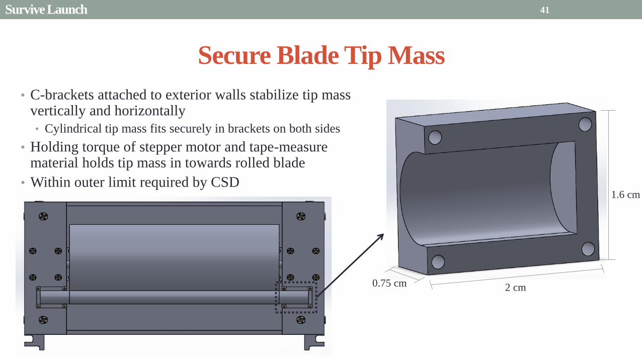

Presentation Sections
bull Purpose and Objectives
bull GHOST Design Solution
bull Critical Project Elements
bull Requirement Satisfaction
bull Controlled Deployment Rate
bull Pitching
bull Survive Launch
bull ElectronicsSoftware Integration
bull Manufacturing the CubeSat
bull Summary
bull Remaining Risks
bull Verification and Validation of Design
bull Project Planning
42
Service Loop
Power and input wires needed in for stepper
motor in deployment module
bull 4 12A rated wires AWG 21 D = 073 mm
bull Full loop around pitching axle to allow for
plusmn90deg rotational freedom
bull 1 cm diameter hole through each plate
bull Current must run throughout launch to
keep holding torque
bull Need not worry about freezing later in mission
Wires (red) exit opening in wall loops around
pitching axle enters opening in opposite wall
43 ElectronicsSoftware Integration
Electrical Block Diagram
Micro-
controller
35 V Supply
Stepper
Driver
Stepper
Motor
H4
H5
H3
H6
Key IO
CCP
Power
Serial
GND
Sensor
VDD
M0
M1
ENABLE
CONFIG
GND
DIR
STEP
E0
E2
B2
B1
A1
A2
VMOT GND VDD
5 V Supply
GND
Servo
Driver 1
Servo 1 TX RX
P G A B C
5V GND U V W Servo
Driver 2
Servo 2
P G A B C
5V GND C2 C3 C4 U V W
Encoder
J2 J3 J4 J5 J6 J7
VDC G
C0
(Speed Set)
C0
(Speed Set)
RS 232
DAC
A B C
Encoder VDC G A B C
B5 B4
A3
A7
B7
B6
D4
D3
D4 D3
C2 C3 C4
VoutA
VoutB
SCLK CS
DIN
GND
Tin Rout Vin GND
VDD
A4
SLEEP
FAULT H0
E1
44 ElectronicsSoftware Integration
Microcontroller PIC18F87K22
Board Requirements
bull Serial output for communication with computer
and servomotor controller
bullDAC used for servomotor communication
bull I0 ports for stepper driver interface
bull CCP port for stepper driver interface
bull Header pins for the encoder interface
Total
18 IO
1 CCP
1 TXRX
bull Would need more IO and CCP ports for a second
stepper motor driver
bull Unused ports 37 IO and 10 CCPECCP
ElectronicsSoftware Integration
PCB Design
bull 2 Layer Board
bull FR4 material
bull 1 oz Copper traces
bull Estimated Dimension = 5times5 cm
bull (See Appendix for Electrical Schematic)
EasyPIC PRO
v7 Pinout
80 Pin Development
Board
ElectronicsSoftware Integration
Incompatible Industrial Boards
Presentation Sections
bull Purpose and Objectives
bull GHOST Design Solution
bull Critical Project Elements
bull Requirement Satisfaction
bull Controlled Deployment Rate
bull Pitching
bull Survive Launch
bull ElectronicsSoftware Integration
bull Manufacturing the CubeSat
bull Summary
bull Remaining Risks
bull Verification and Validation of Design
bull Project Planning
47
Manufacturing In-House vs Purchasing
48
Part In-House Purchase Details
CubeSat walls Aluminum will be purchased with correct thickness and
manufactured to needed dimensions
Blade and pitching axle Axles can be cut down to needed length
Corner brackets Brackets can be altered to fit needed dimensions
S-brackets and C-brackets Will have to be machined to fit strict dimensions
Tip mass Tip mass can be cut down to needed length
Tape-measure material Purchased from McMaster-Carr
Solar sail blade material Blade material is provided for free by NASA LaRC
Launch Locks Launch locks we will use are a screw and bolt
Launch Tabs for CSD Tabs must meet strict dimensions to fit into CSD from
Planetary Systems Corporation
Hub to attach pitching axle to blade module Will have to be machined to meet needed dimensions
Screwsnutsbolts All can be purchased in various sizes and lengths
Motorsencoders and motor drivers All purchased to meet necessary requirements
Electronics board Will have to be made to accommodate needed electronics
Stabilizers to hold pitching motors Will have to be machined to properly fit around motors
Manufacturing the CubeSat
Assembly Procedure
49 Manufacturing the CubeSat
Bonding Mylar to Spool and Stiff Material
bull Loctite Super Glue Professional
bull Shear strength of 01 Nmm2
bull Cross-Sectional Area = 6575 mm2
bull Shear Stress = 33e-4 Nmm2
bull Blade will retain 4 rolls around axle at
final length
bull Loctite to bond stainless steel stiff
material to Mylar and to spool
F = mg = 217 N
Motor
Blade frac14 of roll glued
50 Manufacturing the CubeSat
Fixing Deployment Motor to S-Bracket
51
bull Deployment stepper motor is attached to S-bracket
bull S-bracket stabilized to back of blade deployment
module and vertical CubeSat walls
bull Motor is capable of being screwed directly to S-bracket
bull S-bracket has thickness of 18 inch
Holes for screws to
stabilize S-bracket
Hole for motor shaft
or press-fit ball
bearing to attach to
blade axle
Holes to screw motor
to S-bracket
Manufacturing the CubeSat
Pitching Axle Interfaces
bull Pitching axle to motor axle
bull Motor axle (smaller) fits into pitching
axle (larger) using set-screws
bull Pitching Axle to Blade Reel
Module
bull Axle fixed by set screws inside a hub
52
Pitching Axle
Hub
Motor Axle
4 Set Screws
Manufacturing the CubeSat
Presentation Sections
bull Purpose and Objectives
bull GHOST design solution
bull Critical Project Elements
bull Requirement Satisfaction
bull Controlled Deployment Rate
bull Pitching
bull Survive Launch
bull ElectronicSoftware Integration
bull Manufacturing the CubeSat
bull Summary
bull Remaining Risks and Mitigations
bull Verification and Validation of Design
bull Schedule and remaining work
53
Requirements Satisfaction
Aspect Requirement GHOST Specification
Mass 1 kgU 288 kg
Volume lt= 12U 6U
Life Span 4 months Greater than 4 months
Space Applicable
While design does not need to be
space worthy it should be applicable
to being used in space
All components are picked for
realistic use in space with minimal
cost parts and increased life span
54 Summary
Requirements Satisfaction
Aspect Requirement GHOST Specification
Characteristic Acceleration ac ge 01 mms2 ac = 03868 mms2
Sail Aspect Ratio AR ge 1001 AR = 38931
Sail Deployment Speed 1 cms le 10cms ~5 cms
Pitching Range Ability to pitch blades plusmn 90deg Ability to pitch blades plusmn 90deg
Pitching Coordination Multiple blade coordination when
pitching
Can pitch both blades at once either to
same angle or opposite angles
55 Summary
Presentation Sections
bullPurpose and Objectives
bullGHOST Design Solution
bullCritical Project Elements
bullRequirement Satisfaction
bullRemaining Risks
bullVerification and Validation of Design
bullProject Planning
56
Design Risks
Severity
Likelihood Marginal Major
Often Pitch angle error root not
following tip
Occasional Power loss COMM loss
Structural survivability
pitching motor failure
Improbable Small tear in Mylar Deploy too fast stowage
and deployment of Mylar
Axle failure
launch fail
space dust
deployment motor failure
57 Remaining Risks
Logistical Risks
Severity
Likelihood Minor Marginal Major
Often Parts delayed due to US
Postal Service
Occasional Structural consultation
unavailable
Ball vibrations test is not
available machine parts
not done on schedule
Government shutdown and
we canrsquot get Mylar or help
from NASA
Improbable No time for pitching test
High Bay in Fleming is
unavailable motors donrsquot
show up
58 Remaining Risks
Financial Risks
Severity
Likelihood Minor Marginal Major
Often Repurchase parts
Occasional Motor breaks Price of shake table
Improbable Hyper inflation
59 Remaining Risks
Presentation Sections
bullPurpose and Objectives
bullGHOST Design Solution
bullCritical Project Elements
bullRequirement Satisfaction
bullRemaining Risks
bullVerification and Validation of Design
bullProject Planning
60
Deployment System
Validate that the blade is deployed at a constant rate of 1-10 cms in a high bay
room
Verify that the motor can deploy at constant rate
Verify with test that the deployment system does not use more than the maximum power available of 10W
Validate that the blade can successfully deploy a blade with tape measure
material at a constant rate along ground
Verify with demonstration that the tape measure material can extend length of
blade
Verification and Validation
Verification and Validation
61
Blade Deployment Testing Information
bull Location Prof Frewrsquos High Bay Lab
bull Scheduled MarchApril with late night access to avoid
scheduling conflicts
bull Measurement Tape measure for distance and video
camera for time
bull Power Delivered 6253A Dual DC Power Supply
delivers 0-20 V and 0-3A
Tape measure
marking
distance up
wall
Kinematic Model
bull Torque from motor drives a constant velocity deployment
120591119898119900119905119900119903 = 120591119903119900119897119897 + 120591119901119906119904ℎ119894119899119892 119879119872 minus 120591119892119903119886119907119894119905119910 119879119872
120591119903119900119897119897 =119889119868119903119900119897119897
119889119905120596119903119900119897119897 + 119868119903119900119897119897
119889120596119903119900119897119897
119889119905
120591119901119906119904ℎ119894119899119892 119879119872 =119889119898119890119909119905
119889119905119903119903119900119897119897119907 + 119898119890119909119905
119889119903119903119900119897119897
119889119905119907
120591119892119903119886119907119894119905119910 119879119872 = 119898119890119909119905119903119903119900119897119897119892 bull 120649119945119952119949119941119946119951119944 = 120782 120782120790120787 N∙m 120649119950119952119941119942119949119950119938119961 = 120782 120782120782120789 N∙m
Power Supply
Verification and Validation
CubeSat Wire
62
Pitching System
Validate that the blade reel modules experience coordinated pitching
Verify that one blade reel module experiences periodic
motion
Verify that the blade reel module rotates to 0deg upon
initialization
Verify that the blade pitches to a given command
angle
Verify that the motorencoder system does not exceed power
available
Verification and Validation
Verification and Validation
63
Verify Pitching Angle Experiment Equipment and Specs
bull Use R60D RVIT (Rotary Variable Inductance Transducer) sensor to measure angles attaches to pin (red) in line with pitching axis bull Measures ranges of plusmn60deg rotation
bull Input Voltage = plusmn15 V
bull Output Voltage = plusmn75 V
bull Resolution = 0125 Vdeg
bull 119891119898119886119909 = 20 Hz
bull Use AD524 Precision Amplifier Instrumentation for signal conditioning bull Input Voltage plusmn10 V
bull Output Voltage plusmn10V
bull Requires Supply Voltage plusmn15
bull Use NI 9201 bull Input Voltage plusmn10 V
bull Has a USB output that can connect to a computer where vi program records
Experiment Set-Up
R60D RVIT
AD524
NI 9201 PC via USB
Verification and Validation 64
Verify Periodic Motion Experiment
bull Using the R60D RVIT set-up to measure deflection angles
bull With data of the angle deflection 120579 angular velocity 120596 and angular acceleration 120572 can be measured bull Motor restriction 120591119898119886119909 = 032 Nmiddotm
bull Model restriction 120596119898119886119909 = Ω2 if Ω = 2rpm 120596119898119886119909 = 02094 rads
Validation Model
bull R60D RVIT measures plusmn60deg deflection angles bull Critical condition blade reel module pitches plusmn90deg Ω=2rpm
bull 120572119888 = 00172 rads2 and 120596119898 = 0164 rads thus 120591119898 = 0083 mNmiddotm (119868119898119900119889 = 00048 kgmiddotm2)
120579 119905 120596 119905 120572 119905
Verification and Validation 65
Verification and Validation
Structural System
Validate that the final design can survive launch by using a shake
table
Verify the structural integrity by demonstrating that all stationary parts are
static
Verification and Validation 66
Trade Study FEM vs Vibration Table
Cost Time Experience
Similar to
Actual
Launch
Guaranteed Can
Do Total
FEM 4 1 1 3 4 215
Vibration
Table 2 3 4 4 2 32
Weight () 5 30 25 20 20 100
67 Verification and Validation
See Appendix for Full Trade Study
Validate Structural Stability
bull Will use a shaker table from Ball Aerospace
bull Cost = $250hr
bull Schedule Time to be determined in April
bull Specifications Peak vibration occurs with 34g at
frequency of 16 Hz (Saturn V)
bull Will be verified by examining the structural integrity
of the manufacturing
Verification and Validation 68
CubeSat
Shake Table
Presentation Sections
bullPurpose and Objectives
bullGHOST Design Solution
bullCritical Project Elements
bullRequirement Satisfaction
bullRemaining Risks
bullVerification and Validation of Design
bullProject Planning
69
Organizational Chart
Mark
Dolezal
Emily
Proano
Lauren
Persons
Casey
Myers
Nicholas
Busbey
Taylor
Smith
Karynna
Tuan
Megan
Scheele
Project
Manager
Software
Lead
Electrical
Lead
Systems Test and
Safety
Manufacturing
Lead Mechanics
Lead
CFO and
Materials
Lead
Organizing
team
meetings
Supporting
other leads
Non CPE
Tasks
Deployment
Control
Pitching
Control Motors and
Electronics
Power
Integrate
all system Perform
and Plan
tests
Manufacture
all in-house
parts
SolidWorks
Keep track
of financial
spending
Right
materials
are being
utilized
CubeSat
Assembly
Specific
System
Requirements
70 Project Planning
GHOST
Materials Mechanical Electrical Software Documents
Shake Table
Vibration
Analysis
Mechanical
Layout
Power Budget Pitch Control
Algorithm
Deployment
Rate Control
Algorithm SolidWorks
Model
Electrical
Wiring Layout
Thermodynamic
Analysis of
Electronic System
Mass Budget
Prototype of
CubeSat Bus
Motor
Subsystem
CDR
FFR
Spring
Schedule
Financial
Budget
Work Breakdown Structure (WBS)
Mylar from
NASA
Spin Up
Algorithm
Emergency
StopRestart System
71 Project Planning
PCB Design
Spring
Documents
113 120 127 203 210 217 224 303 310 317 324 331 407 414 421 428
MSR TRR SFR PFR
Time (date)
Purchase
motorsdrivers
Preliminary code
Electronic
integration
Test code
Electronicscode
interface
Purchase
raw materials
Manufacture frame
Assemble bus
Manufacture
remaining parts
Integrate system
Deployment test
Pitching test
Vibration test
Ta
sks
72
GHOST Spring Schedule
Project Planning
Planned Uncertainty
Key
Test Plan Test Scheduled Facility Specialized Equipment
Verify Pitch Angle 317 ITLL R60D RVIT NI 9201 AD524 Oscilloscope bench
power source
Zero Pitch Angle 317 ITLL R60D RVIT NI 9201 AD524 Oscilloscope bench
power source
Measure power used in
pitchdeployment 317 ITLL Ammeter voltmeter bench power source
Verify constant deployment 324 ITLL Firewire camera bench power source
ASEN2003BallTrackervi
Verify periodic motion 324 ITLL R60D RVIT NI 9201 AD524 Oscilloscope bench
power source
Validate tape measure ground
deployment 331 ITLL
Bench power source tape measure stop watch rollers
for tip mass
Validate coordinated pitching 331 ITLL R60D RVIT NI 9201 AD524 oscilloscope bench
power source
Validate 1g blade deployment 331-414 Prof Frew
high bay
Portable 6253A Dual DC Power Supply ladder tape
measure video camera
Validate launch ready 414 Ball Aero Shake Table
Project Planning 73
Cost Table ndash Structural Components
Part Price per
part NeededVolume Needed Total Price Supplier
Aluminum 6061 Sheet
(18rdquo thick) $ 8976 2ft times 2ft times 18 in $ 8976 The Metals Depot
Aluminum 6061 rod
(14 in diameter) $280 2 ft $280 The Metals Depot
Aluminum6061 rod
(716 in diameter) $494 2 ft $494 The Metals Depot
Steel Corner Brackets
(34rdquo times 12rdquo)
$197 4
braces 16 $788 Home Depot
Hardened 302 Stainless
Steel $3300 2 cm times 5 m times 127 microm $3300 McMaster-Carr
Total $11834
74 Project Planning
Cost Table ndash Electrical Components
Part Price per
part Needed Total Price Supplier
Sanyo Stepper Motor $ 5995 2 $11990 Pololu Electronics and Robotics
DRV8834 Low-Voltage Stepper
Motor Driver $995 2 $1990 Pololu Electronics and Robotics
FAULHABER 2036 BLDC
Servo Motor $23000 2 $46000 MicroMo Micro Motion Solutions
Atmel ATA6832-DK Brushless
DC Motor Controller $20800 2 $41600 Atmel
Encoder AU-ZSD1000A $22500 2 $45000 MicroMo Micro Motion Solutions
PIC18F87K22 Microcontroller $500 1 $500 Microchip
AD-524 Signal Converter $1767 1 $1767 Agilent
Total $148847
75 Project Planning
Questions
76
References
bull wwwloctiteproductscom
bull Vallado D A Fundamentals of Astrodynamics and Applications
bull Guerrant D Lawrence D Heaton A Earth Escape Capabilities of the Heliogyro Sail AIAA Paper
bull wwwspaceflightnowcom
bull Guerrant D HGVizGuim MATLAB Program
bull httpwwwmicromocombrushless-dc-motorsaspx
bull httpwwwfaulhabercomservletcomitmrwawservletAnzeigefremdaufruf=jaampkdid=40929ampsprachid=1amphtdigurl=n169933i95222html
bull httpwwwpololucom
bull httpasmmatwebcomsearchSpecificMaterialaspbassnum=MA6061t6
bull httpwwwruagcomthermalSpace_Thermal_HardwareMulti_Layer_Insulation
bull Helgesen Bryan Sierra Nevada Corporation
77
GyroSail Launch Configuration and Deployment Sequence
78
1 Launch configuration (6U) 2 Blade reel modules pitch to zero Fits within a 6U or 12U dispenser
3 PV arrays deploy
Other array configurations are possible
williamkwilkienasagov NASA PREDECISIONAL - FOR DISCUSSION PURPOSES ONLY
78 Appendix
GyroSail Primary Bus Systems Based on modified JPLU MichUCLACal PolyUT INSPIRE bus
williamkwilkienasagov
05U cold gas thruster ACS for detumbling
and initial spin-up
(httpwwwaustinsatnet)
05U EPS battery CampDH UHF backup
comms (U Mich) 05U DSN-compatible X-band
communications (JPL)
05U COTS star trackerimager ADC (BCT) sail
module processor (CU)
Klesh A et al 2013 ldquoINSPIRE Interplanetary NanoSpacecraft Pathfinder In Relevant Environmentrdquo Proceedings of the AIAAUSU Conference on Small Satellites Around the Corner SSC13-
XI-8 httpdigitalcommonsusuedusmallsat2013all2013127
NASA PREDECISIONAL - FOR DISCUSSION PURPOSES ONLY
79 Appendix
COMM Subsystem
bull 18 m Ka-band antennas at White
Sands New Mexico
bull Goddard Space Flight Center
Greebelt Maryland USA
supplied the Mulemba Space
Center in Angola
80 Appendix
Orion Crew
Module
6U Canisterized Satellite
Dispenser (CSD) ESPA Ring
Spacecraft
Adapter
Interim Cryogenic Propulsion
Stage (ICPS)
Secondary Payload Attachment to SLS
The SLS design is currently going through CDR An ESPA
ring is not currently in place but is mentioned in the SLS
CONOPS in order to accommodate secondary payloads
81 Appendix
Max Thrust Condition Collective 90deg pitch profile
Max thrust normal to orbital plane
(Halo orbits orbital plane rotation ie
inclination change)
82
Credit to Dan Guerrant
Appendix
Max Thrust Condition
F vs β M vs β
83
Credit to Dan Guerrant
Appendix
No Thrust Condition Collective 0deg pitch profile
Zero thrust
84
Credit to Dan Guerrant
Appendix
No Thrust Condition
F vs β M vs β
85
Credit to Dan Guerrant
Appendix
Max Torque Condition Collective 35deg pitch profile
Max torque used for spinning up sc
(opposite orientation for despinning)
86
Credit to Dan Guerrant
Appendix
Max Torque Condition
F vs β M vs β
87
Credit to Dan Guerrant
Appendix
Max In-Plane Thrust Condition Cyclic 35deg pitch profile
Max thrust in in-plane (d2) direction for orbit raising
88
Credit to Dan Guerrant
Appendix
Max In-Plane Thrust Condition
F vs β M vs β
89
Credit to Dan Guerrant
Appendix
Orbit Raising
F
90 Appendix
Thermal Space Concerns
bull Material Concerns
bull Aluminum 6061 -196 degC to 160deg C
bull Electronics Concerns
bull Typical Operating Temperature -55 to 80 degC
bull Countermeasures
bull Multi-layer Insulation AAErotherm S10-190
bull (0005 ndash 0035 Wm2K)
bull Battery operated heaters for pre-sail deployment
Multi-layer Insulation
Layer 1 1 x Outer layer
Layer 2 8 x 03 mil VDAPolyimideVDA perf
8 x Woven Polyester netting
Layer 3 1 x Outer layer
Layer 4 1 x Woven Polyester netting
91 Appendix
Rolled Up Blade Reel Calculation Optimal Sail Length 545 m ndash Sail chord of 14 cm
Max Diameter of Spool 598 cm
Diameter of Axle 05 cm
Length of Stiff Material 5 m
Dimension of Stiff Material 5 m times 2 cm times 127 microm
92 Appendix
Torque calculation
bull Note current calculated via T=kI (where T is torque I is amp k is the torque
constant specific to the motor)
T = kI
(k = 005 NmA)
93 Appendix
Servo Controller
94 Appendix
Encoder Dimensions and Interface
bull FAULHABER IE2-1024
95 Appendix
Stepper Motor Torque
96 Appendix
Motor Phases (Stepper)
97 Appendix
98 Appendix
99 Appendix
100 Appendix
101 Appendix
Microcontroller
102 Appendix
ATA6832 Phase Output Chip
103 Appendix
ATA6624 Bypassed Chip
bull Bypassed chip
on servo controller
104 Appendix
Power Budget
105 Appendix
Wire Gauge
bull Stepper Motor 26AWG (04 mm diameter)
bull Servomotor 24 AWG (051 mm diameter)
bull Encoder 24 AWG
Voltage Drop () AWG Max Gauge
001 5
01 15
1 25
5 32
NOTE Voltage drop calculated at 1A and 40 cm of wire
106
24 AWG Wire
Appendix
Trade Study ndash FEM vs Vibration Table
Factor 4 3 2 1
Cost No money 0 gt C gt $100 $100 gt C gt $300 $300 lt C
Time 0 min lt T lt 30 min 30 min lt T lt 2 hrs 2 hrs lt T lt 1 day 1day lt T
Experience Everyone has
experience
A couple people
know how to
1 person has
experience
No one has
experience
Similar To Actual
Launch Simulate real launch
Doesnrsquot have all
variables experienced
Has only a couple
similarities
No similarities to
launch
Guaranteed Can Do
Donrsquot need any
outside equipment or
help
Need outside
equipment but
guaranteed use
Need outside
equipment but own
work at higher
priority
Need outside
equipment but canrsquot
use
Scoring
107 Appendix
Weighting
Weight () Category Reasoning
5 Cost Have a lot of extra $ in the budget
30 Time Have a strict schedule but not a main focus of the
project
25 Experience If no one has experience it will take a lot of time
20 Similar to Actual Launch Needs to be like actual launch
20 Guaranteed Can Do Needs to be able to accomplish but not the most
important focus
108 Appendix
Finite Element Method (FEM)
Objectives Description ProCon
Cost No money because one of us
would do it Pro
Time A lot of time to learn and then
perform FEM Con
Experience No one in group has FEM
experience Con
Similar to Actual Launch Very similar to actual launch Pro
Guaranteed Can Do All we need is paper pen and
theory to do Pro
109 Appendix
Vibration Table
Objective Description ProCons
Cost $250hr Con
Time A hour on the table should simulate
launch Pro
Experience Donrsquot need experience to run
vibration table Pro
Similar to Actual Launch Actually putting our system through
vibration stress Pro
Guaranteed Can Do No guarantee but most likely can Con
110 Appendix
SpinUp State
1 Check value of SpinUp to see if satellite is already spun up
bull Continue if satellite is not already spun-up
2 Deploy the tape stiffened length of the blade
3 Pitch to the spin up angle
4 Wait until characteristic angular velocity is reached
5 Pitch to pre-deployment position
6 Save SpinUp as completed
Appendix 111
Deployment State
1 Check if satellite has been spun up yet
bull Continue if it has
2 Check if blades are already deployed
bull Continue if they havenrsquot
3 Run deploy algorithm until blades are fully deployed
4 Save value saying blades have been deployed
Appendix 112
Pitching State
1 Check if satellite has been spun up
bull Continue if satellite has been spun up
2 Check if blades have been deployed
bull Continue if blades have been deployed
3 Look at commanded pitch profile
4 Find correlated sinusoid command
5 Command servo to pitch angle for the time in the orbit
6 Continue until given a new pitch command
Appendix 113
Emergency Stop
1 Save which state was interrupted
2 Save last position in interrupted
state
3 Wait until Restart command is
received
1 Check two previous states to see
what is being restarted
2 Look at saved last position in
state being restarted
3 Adapt the algorithm of the state
to continue where left off
Restart
Appendix 114
Comparison with Previous Heliogyro Concepts MIT (1989) NASA (2011) GHOST
Total sail craft mass (kg) 18 84
288 (6)
Characteristic acceleration ac
(mms2) 06 10 03868 (01854)
Sail reflective area (m2) 1200 960 1526
Non-sail mass (kg) 5 5 --
Number of sail blades 8 6 2
Blade chord (m) 15 08 014
Blade length (m) 100 200 545
Rotational period (minutes) 3 3 1
Blade root stress (Pa) 8650 34000 --
Blade root allowable stress (Pa) 55 M 55 M --
Blade root tension load (N) 01 007 --
115 Appendix
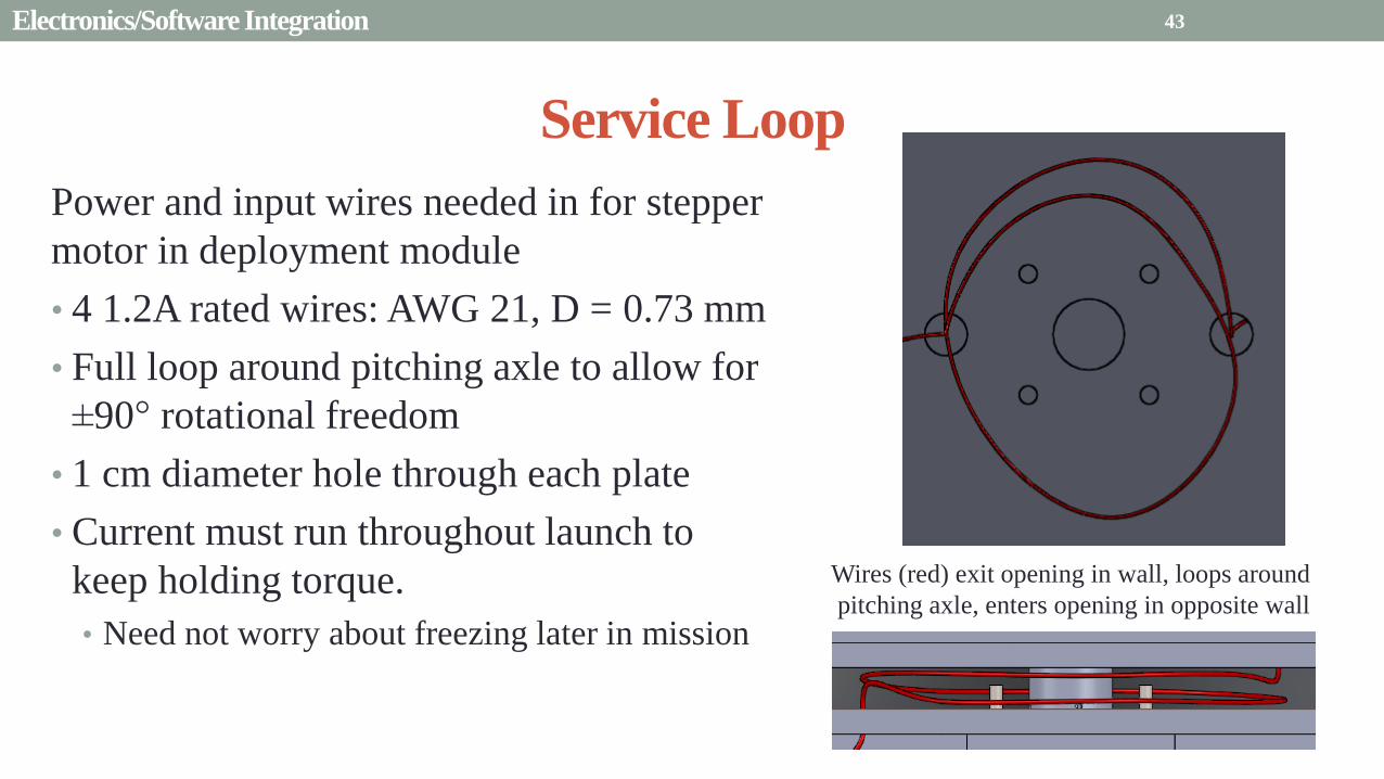
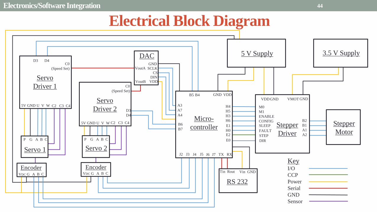
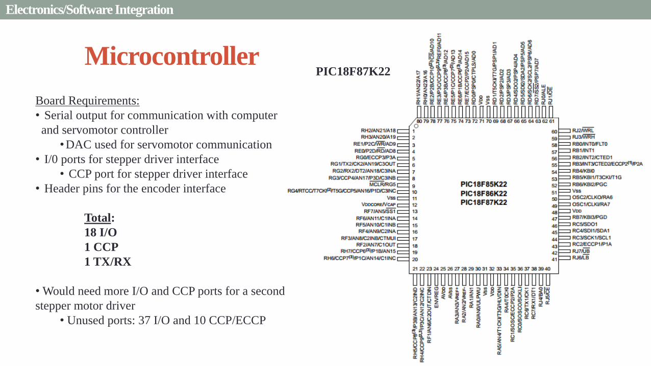
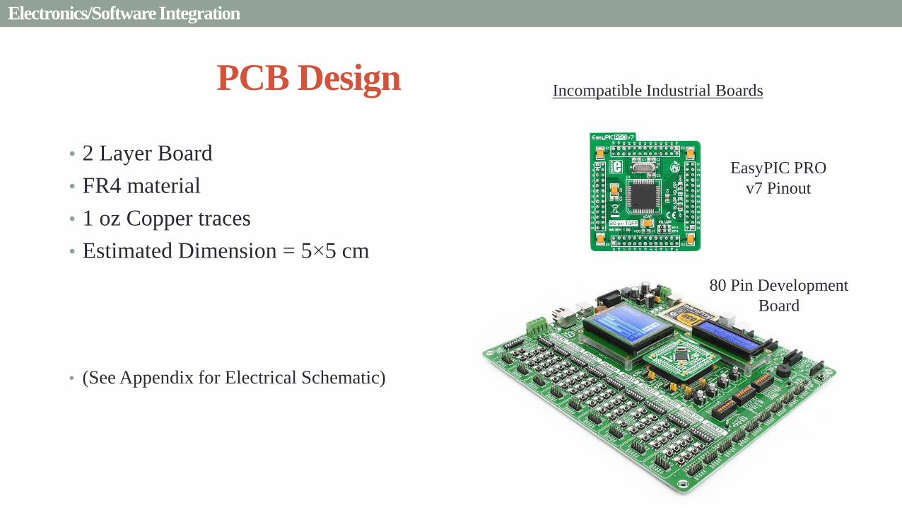
PCB Design
bull 2 Layer Board
bull FR4 material
bull 1 oz Copper traces
bull Estimated Dimension = 5times5 cm
bull (See Appendix for Electrical Schematic)
EasyPIC PRO
v7 Pinout
80 Pin Development
Board
ElectronicsSoftware Integration
Incompatible Industrial Boards
Presentation Sections
bull Purpose and Objectives
bull GHOST Design Solution
bull Critical Project Elements
bull Requirement Satisfaction
bull Controlled Deployment Rate
bull Pitching
bull Survive Launch
bull ElectronicsSoftware Integration
bull Manufacturing the CubeSat
bull Summary
bull Remaining Risks
bull Verification and Validation of Design
bull Project Planning
47
Manufacturing In-House vs Purchasing
48
Part In-House Purchase Details
CubeSat walls Aluminum will be purchased with correct thickness and
manufactured to needed dimensions
Blade and pitching axle Axles can be cut down to needed length
Corner brackets Brackets can be altered to fit needed dimensions
S-brackets and C-brackets Will have to be machined to fit strict dimensions
Tip mass Tip mass can be cut down to needed length
Tape-measure material Purchased from McMaster-Carr
Solar sail blade material Blade material is provided for free by NASA LaRC
Launch Locks Launch locks we will use are a screw and bolt
Launch Tabs for CSD Tabs must meet strict dimensions to fit into CSD from
Planetary Systems Corporation
Hub to attach pitching axle to blade module Will have to be machined to meet needed dimensions
Screwsnutsbolts All can be purchased in various sizes and lengths
Motorsencoders and motor drivers All purchased to meet necessary requirements
Electronics board Will have to be made to accommodate needed electronics
Stabilizers to hold pitching motors Will have to be machined to properly fit around motors
Manufacturing the CubeSat
Assembly Procedure
49 Manufacturing the CubeSat
Bonding Mylar to Spool and Stiff Material
bull Loctite Super Glue Professional
bull Shear strength of 01 Nmm2
bull Cross-Sectional Area = 6575 mm2
bull Shear Stress = 33e-4 Nmm2
bull Blade will retain 4 rolls around axle at
final length
bull Loctite to bond stainless steel stiff
material to Mylar and to spool
F = mg = 217 N
Motor
Blade frac14 of roll glued
50 Manufacturing the CubeSat
Fixing Deployment Motor to S-Bracket
51
bull Deployment stepper motor is attached to S-bracket
bull S-bracket stabilized to back of blade deployment
module and vertical CubeSat walls
bull Motor is capable of being screwed directly to S-bracket
bull S-bracket has thickness of 18 inch
Holes for screws to
stabilize S-bracket
Hole for motor shaft
or press-fit ball
bearing to attach to
blade axle
Holes to screw motor
to S-bracket
Manufacturing the CubeSat
Pitching Axle Interfaces
bull Pitching axle to motor axle
bull Motor axle (smaller) fits into pitching
axle (larger) using set-screws
bull Pitching Axle to Blade Reel
Module
bull Axle fixed by set screws inside a hub
52
Pitching Axle
Hub
Motor Axle
4 Set Screws
Manufacturing the CubeSat
Presentation Sections
bull Purpose and Objectives
bull GHOST design solution
bull Critical Project Elements
bull Requirement Satisfaction
bull Controlled Deployment Rate
bull Pitching
bull Survive Launch
bull ElectronicSoftware Integration
bull Manufacturing the CubeSat
bull Summary
bull Remaining Risks and Mitigations
bull Verification and Validation of Design
bull Schedule and remaining work
53
Requirements Satisfaction
Aspect Requirement GHOST Specification
Mass 1 kgU 288 kg
Volume lt= 12U 6U
Life Span 4 months Greater than 4 months
Space Applicable
While design does not need to be
space worthy it should be applicable
to being used in space
All components are picked for
realistic use in space with minimal
cost parts and increased life span
54 Summary
Requirements Satisfaction
Aspect Requirement GHOST Specification
Characteristic Acceleration ac ge 01 mms2 ac = 03868 mms2
Sail Aspect Ratio AR ge 1001 AR = 38931
Sail Deployment Speed 1 cms le 10cms ~5 cms
Pitching Range Ability to pitch blades plusmn 90deg Ability to pitch blades plusmn 90deg
Pitching Coordination Multiple blade coordination when
pitching
Can pitch both blades at once either to
same angle or opposite angles
55 Summary
Presentation Sections
bullPurpose and Objectives
bullGHOST Design Solution
bullCritical Project Elements
bullRequirement Satisfaction
bullRemaining Risks
bullVerification and Validation of Design
bullProject Planning
56
Design Risks
Severity
Likelihood Marginal Major
Often Pitch angle error root not
following tip
Occasional Power loss COMM loss
Structural survivability
pitching motor failure
Improbable Small tear in Mylar Deploy too fast stowage
and deployment of Mylar
Axle failure
launch fail
space dust
deployment motor failure
57 Remaining Risks
Logistical Risks
Severity
Likelihood Minor Marginal Major
Often Parts delayed due to US
Postal Service
Occasional Structural consultation
unavailable
Ball vibrations test is not
available machine parts
not done on schedule
Government shutdown and
we canrsquot get Mylar or help
from NASA
Improbable No time for pitching test
High Bay in Fleming is
unavailable motors donrsquot
show up
58 Remaining Risks
Financial Risks
Severity
Likelihood Minor Marginal Major
Often Repurchase parts
Occasional Motor breaks Price of shake table
Improbable Hyper inflation
59 Remaining Risks
Presentation Sections
bullPurpose and Objectives
bullGHOST Design Solution
bullCritical Project Elements
bullRequirement Satisfaction
bullRemaining Risks
bullVerification and Validation of Design
bullProject Planning
60
Deployment System
Validate that the blade is deployed at a constant rate of 1-10 cms in a high bay
room
Verify that the motor can deploy at constant rate
Verify with test that the deployment system does not use more than the maximum power available of 10W
Validate that the blade can successfully deploy a blade with tape measure
material at a constant rate along ground
Verify with demonstration that the tape measure material can extend length of
blade
Verification and Validation
Verification and Validation
61
Blade Deployment Testing Information
bull Location Prof Frewrsquos High Bay Lab
bull Scheduled MarchApril with late night access to avoid
scheduling conflicts
bull Measurement Tape measure for distance and video
camera for time
bull Power Delivered 6253A Dual DC Power Supply
delivers 0-20 V and 0-3A
Tape measure
marking
distance up
wall
Kinematic Model
bull Torque from motor drives a constant velocity deployment
120591119898119900119905119900119903 = 120591119903119900119897119897 + 120591119901119906119904ℎ119894119899119892 119879119872 minus 120591119892119903119886119907119894119905119910 119879119872
120591119903119900119897119897 =119889119868119903119900119897119897
119889119905120596119903119900119897119897 + 119868119903119900119897119897
119889120596119903119900119897119897
119889119905
120591119901119906119904ℎ119894119899119892 119879119872 =119889119898119890119909119905
119889119905119903119903119900119897119897119907 + 119898119890119909119905
119889119903119903119900119897119897
119889119905119907
120591119892119903119886119907119894119905119910 119879119872 = 119898119890119909119905119903119903119900119897119897119892 bull 120649119945119952119949119941119946119951119944 = 120782 120782120790120787 N∙m 120649119950119952119941119942119949119950119938119961 = 120782 120782120782120789 N∙m
Power Supply
Verification and Validation
CubeSat Wire
62
Pitching System
Validate that the blade reel modules experience coordinated pitching
Verify that one blade reel module experiences periodic
motion
Verify that the blade reel module rotates to 0deg upon
initialization
Verify that the blade pitches to a given command
angle
Verify that the motorencoder system does not exceed power
available
Verification and Validation
Verification and Validation
63
Verify Pitching Angle Experiment Equipment and Specs
bull Use R60D RVIT (Rotary Variable Inductance Transducer) sensor to measure angles attaches to pin (red) in line with pitching axis bull Measures ranges of plusmn60deg rotation
bull Input Voltage = plusmn15 V
bull Output Voltage = plusmn75 V
bull Resolution = 0125 Vdeg
bull 119891119898119886119909 = 20 Hz
bull Use AD524 Precision Amplifier Instrumentation for signal conditioning bull Input Voltage plusmn10 V
bull Output Voltage plusmn10V
bull Requires Supply Voltage plusmn15
bull Use NI 9201 bull Input Voltage plusmn10 V
bull Has a USB output that can connect to a computer where vi program records
Experiment Set-Up
R60D RVIT
AD524
NI 9201 PC via USB
Verification and Validation 64
Verify Periodic Motion Experiment
bull Using the R60D RVIT set-up to measure deflection angles
bull With data of the angle deflection 120579 angular velocity 120596 and angular acceleration 120572 can be measured bull Motor restriction 120591119898119886119909 = 032 Nmiddotm
bull Model restriction 120596119898119886119909 = Ω2 if Ω = 2rpm 120596119898119886119909 = 02094 rads
Validation Model
bull R60D RVIT measures plusmn60deg deflection angles bull Critical condition blade reel module pitches plusmn90deg Ω=2rpm
bull 120572119888 = 00172 rads2 and 120596119898 = 0164 rads thus 120591119898 = 0083 mNmiddotm (119868119898119900119889 = 00048 kgmiddotm2)
120579 119905 120596 119905 120572 119905
Verification and Validation 65
Verification and Validation
Structural System
Validate that the final design can survive launch by using a shake
table
Verify the structural integrity by demonstrating that all stationary parts are
static
Verification and Validation 66
Trade Study FEM vs Vibration Table
Cost Time Experience
Similar to
Actual
Launch
Guaranteed Can
Do Total
FEM 4 1 1 3 4 215
Vibration
Table 2 3 4 4 2 32
Weight () 5 30 25 20 20 100
67 Verification and Validation
See Appendix for Full Trade Study
Validate Structural Stability
bull Will use a shaker table from Ball Aerospace
bull Cost = $250hr
bull Schedule Time to be determined in April
bull Specifications Peak vibration occurs with 34g at
frequency of 16 Hz (Saturn V)
bull Will be verified by examining the structural integrity
of the manufacturing
Verification and Validation 68
CubeSat
Shake Table
Presentation Sections
bullPurpose and Objectives
bullGHOST Design Solution
bullCritical Project Elements
bullRequirement Satisfaction
bullRemaining Risks
bullVerification and Validation of Design
bullProject Planning
69
Organizational Chart
Mark
Dolezal
Emily
Proano
Lauren
Persons
Casey
Myers
Nicholas
Busbey
Taylor
Smith
Karynna
Tuan
Megan
Scheele
Project
Manager
Software
Lead
Electrical
Lead
Systems Test and
Safety
Manufacturing
Lead Mechanics
Lead
CFO and
Materials
Lead
Organizing
team
meetings
Supporting
other leads
Non CPE
Tasks
Deployment
Control
Pitching
Control Motors and
Electronics
Power
Integrate
all system Perform
and Plan
tests
Manufacture
all in-house
parts
SolidWorks
Keep track
of financial
spending
Right
materials
are being
utilized
CubeSat
Assembly
Specific
System
Requirements
70 Project Planning
GHOST
Materials Mechanical Electrical Software Documents
Shake Table
Vibration
Analysis
Mechanical
Layout
Power Budget Pitch Control
Algorithm
Deployment
Rate Control
Algorithm SolidWorks
Model
Electrical
Wiring Layout
Thermodynamic
Analysis of
Electronic System
Mass Budget
Prototype of
CubeSat Bus
Motor
Subsystem
CDR
FFR
Spring
Schedule
Financial
Budget
Work Breakdown Structure (WBS)
Mylar from
NASA
Spin Up
Algorithm
Emergency
StopRestart System
71 Project Planning
PCB Design
Spring
Documents
113 120 127 203 210 217 224 303 310 317 324 331 407 414 421 428
MSR TRR SFR PFR
Time (date)
Purchase
motorsdrivers
Preliminary code
Electronic
integration
Test code
Electronicscode
interface
Purchase
raw materials
Manufacture frame
Assemble bus
Manufacture
remaining parts
Integrate system
Deployment test
Pitching test
Vibration test
Ta
sks
72
GHOST Spring Schedule
Project Planning
Planned Uncertainty
Key
Test Plan Test Scheduled Facility Specialized Equipment
Verify Pitch Angle 317 ITLL R60D RVIT NI 9201 AD524 Oscilloscope bench
power source
Zero Pitch Angle 317 ITLL R60D RVIT NI 9201 AD524 Oscilloscope bench
power source
Measure power used in
pitchdeployment 317 ITLL Ammeter voltmeter bench power source
Verify constant deployment 324 ITLL Firewire camera bench power source
ASEN2003BallTrackervi
Verify periodic motion 324 ITLL R60D RVIT NI 9201 AD524 Oscilloscope bench
power source
Validate tape measure ground
deployment 331 ITLL
Bench power source tape measure stop watch rollers
for tip mass
Validate coordinated pitching 331 ITLL R60D RVIT NI 9201 AD524 oscilloscope bench
power source
Validate 1g blade deployment 331-414 Prof Frew
high bay
Portable 6253A Dual DC Power Supply ladder tape
measure video camera
Validate launch ready 414 Ball Aero Shake Table
Project Planning 73
Cost Table ndash Structural Components
Part Price per
part NeededVolume Needed Total Price Supplier
Aluminum 6061 Sheet
(18rdquo thick) $ 8976 2ft times 2ft times 18 in $ 8976 The Metals Depot
Aluminum 6061 rod
(14 in diameter) $280 2 ft $280 The Metals Depot
Aluminum6061 rod
(716 in diameter) $494 2 ft $494 The Metals Depot
Steel Corner Brackets
(34rdquo times 12rdquo)
$197 4
braces 16 $788 Home Depot
Hardened 302 Stainless
Steel $3300 2 cm times 5 m times 127 microm $3300 McMaster-Carr
Total $11834
74 Project Planning
Cost Table ndash Electrical Components
Part Price per
part Needed Total Price Supplier
Sanyo Stepper Motor $ 5995 2 $11990 Pololu Electronics and Robotics
DRV8834 Low-Voltage Stepper
Motor Driver $995 2 $1990 Pololu Electronics and Robotics
FAULHABER 2036 BLDC
Servo Motor $23000 2 $46000 MicroMo Micro Motion Solutions
Atmel ATA6832-DK Brushless
DC Motor Controller $20800 2 $41600 Atmel
Encoder AU-ZSD1000A $22500 2 $45000 MicroMo Micro Motion Solutions
PIC18F87K22 Microcontroller $500 1 $500 Microchip
AD-524 Signal Converter $1767 1 $1767 Agilent
Total $148847
75 Project Planning
Questions
76
References
bull wwwloctiteproductscom
bull Vallado D A Fundamentals of Astrodynamics and Applications
bull Guerrant D Lawrence D Heaton A Earth Escape Capabilities of the Heliogyro Sail AIAA Paper
bull wwwspaceflightnowcom
bull Guerrant D HGVizGuim MATLAB Program
bull httpwwwmicromocombrushless-dc-motorsaspx
bull httpwwwfaulhabercomservletcomitmrwawservletAnzeigefremdaufruf=jaampkdid=40929ampsprachid=1amphtdigurl=n169933i95222html
bull httpwwwpololucom
bull httpasmmatwebcomsearchSpecificMaterialaspbassnum=MA6061t6
bull httpwwwruagcomthermalSpace_Thermal_HardwareMulti_Layer_Insulation
bull Helgesen Bryan Sierra Nevada Corporation
77
GyroSail Launch Configuration and Deployment Sequence
78
1 Launch configuration (6U) 2 Blade reel modules pitch to zero Fits within a 6U or 12U dispenser
3 PV arrays deploy
Other array configurations are possible
williamkwilkienasagov NASA PREDECISIONAL - FOR DISCUSSION PURPOSES ONLY
78 Appendix
GyroSail Primary Bus Systems Based on modified JPLU MichUCLACal PolyUT INSPIRE bus
williamkwilkienasagov
05U cold gas thruster ACS for detumbling
and initial spin-up
(httpwwwaustinsatnet)
05U EPS battery CampDH UHF backup
comms (U Mich) 05U DSN-compatible X-band
communications (JPL)
05U COTS star trackerimager ADC (BCT) sail
module processor (CU)
Klesh A et al 2013 ldquoINSPIRE Interplanetary NanoSpacecraft Pathfinder In Relevant Environmentrdquo Proceedings of the AIAAUSU Conference on Small Satellites Around the Corner SSC13-
XI-8 httpdigitalcommonsusuedusmallsat2013all2013127
NASA PREDECISIONAL - FOR DISCUSSION PURPOSES ONLY
79 Appendix
COMM Subsystem
bull 18 m Ka-band antennas at White
Sands New Mexico
bull Goddard Space Flight Center
Greebelt Maryland USA
supplied the Mulemba Space
Center in Angola
80 Appendix
Orion Crew
Module
6U Canisterized Satellite
Dispenser (CSD) ESPA Ring
Spacecraft
Adapter
Interim Cryogenic Propulsion
Stage (ICPS)
Secondary Payload Attachment to SLS
The SLS design is currently going through CDR An ESPA
ring is not currently in place but is mentioned in the SLS
CONOPS in order to accommodate secondary payloads
81 Appendix
Max Thrust Condition Collective 90deg pitch profile
Max thrust normal to orbital plane
(Halo orbits orbital plane rotation ie
inclination change)
82
Credit to Dan Guerrant
Appendix
Max Thrust Condition
F vs β M vs β
83
Credit to Dan Guerrant
Appendix
No Thrust Condition Collective 0deg pitch profile
Zero thrust
84
Credit to Dan Guerrant
Appendix
No Thrust Condition
F vs β M vs β
85
Credit to Dan Guerrant
Appendix
Max Torque Condition Collective 35deg pitch profile
Max torque used for spinning up sc
(opposite orientation for despinning)
86
Credit to Dan Guerrant
Appendix
Max Torque Condition
F vs β M vs β
87
Credit to Dan Guerrant
Appendix
Max In-Plane Thrust Condition Cyclic 35deg pitch profile
Max thrust in in-plane (d2) direction for orbit raising
88
Credit to Dan Guerrant
Appendix
Max In-Plane Thrust Condition
F vs β M vs β
89
Credit to Dan Guerrant
Appendix
Orbit Raising
F
90 Appendix
Thermal Space Concerns
bull Material Concerns
bull Aluminum 6061 -196 degC to 160deg C
bull Electronics Concerns
bull Typical Operating Temperature -55 to 80 degC
bull Countermeasures
bull Multi-layer Insulation AAErotherm S10-190
bull (0005 ndash 0035 Wm2K)
bull Battery operated heaters for pre-sail deployment
Multi-layer Insulation
Layer 1 1 x Outer layer
Layer 2 8 x 03 mil VDAPolyimideVDA perf
8 x Woven Polyester netting
Layer 3 1 x Outer layer
Layer 4 1 x Woven Polyester netting
91 Appendix
Rolled Up Blade Reel Calculation Optimal Sail Length 545 m ndash Sail chord of 14 cm
Max Diameter of Spool 598 cm
Diameter of Axle 05 cm
Length of Stiff Material 5 m
Dimension of Stiff Material 5 m times 2 cm times 127 microm
92 Appendix
Torque calculation
bull Note current calculated via T=kI (where T is torque I is amp k is the torque
constant specific to the motor)
T = kI
(k = 005 NmA)
93 Appendix
Servo Controller
94 Appendix
Encoder Dimensions and Interface
bull FAULHABER IE2-1024
95 Appendix
Stepper Motor Torque
96 Appendix
Motor Phases (Stepper)
97 Appendix
98 Appendix
99 Appendix
100 Appendix
101 Appendix
Microcontroller
102 Appendix
ATA6832 Phase Output Chip
103 Appendix
ATA6624 Bypassed Chip
bull Bypassed chip
on servo controller
104 Appendix
Power Budget
105 Appendix
Wire Gauge
bull Stepper Motor 26AWG (04 mm diameter)
bull Servomotor 24 AWG (051 mm diameter)
bull Encoder 24 AWG
Voltage Drop () AWG Max Gauge
001 5
01 15
1 25
5 32
NOTE Voltage drop calculated at 1A and 40 cm of wire
106
24 AWG Wire
Appendix
Trade Study ndash FEM vs Vibration Table
Factor 4 3 2 1
Cost No money 0 gt C gt $100 $100 gt C gt $300 $300 lt C
Time 0 min lt T lt 30 min 30 min lt T lt 2 hrs 2 hrs lt T lt 1 day 1day lt T
Experience Everyone has
experience
A couple people
know how to
1 person has
experience
No one has
experience
Similar To Actual
Launch Simulate real launch
Doesnrsquot have all
variables experienced
Has only a couple
similarities
No similarities to
launch
Guaranteed Can Do
Donrsquot need any
outside equipment or
help
Need outside
equipment but
guaranteed use
Need outside
equipment but own
work at higher
priority
Need outside
equipment but canrsquot
use
Scoring
107 Appendix
Weighting
Weight () Category Reasoning
5 Cost Have a lot of extra $ in the budget
30 Time Have a strict schedule but not a main focus of the
project
25 Experience If no one has experience it will take a lot of time
20 Similar to Actual Launch Needs to be like actual launch
20 Guaranteed Can Do Needs to be able to accomplish but not the most
important focus
108 Appendix
Finite Element Method (FEM)
Objectives Description ProCon
Cost No money because one of us
would do it Pro
Time A lot of time to learn and then
perform FEM Con
Experience No one in group has FEM
experience Con
Similar to Actual Launch Very similar to actual launch Pro
Guaranteed Can Do All we need is paper pen and
theory to do Pro
109 Appendix
Vibration Table
Objective Description ProCons
Cost $250hr Con
Time A hour on the table should simulate
launch Pro
Experience Donrsquot need experience to run
vibration table Pro
Similar to Actual Launch Actually putting our system through
vibration stress Pro
Guaranteed Can Do No guarantee but most likely can Con
110 Appendix
SpinUp State
1 Check value of SpinUp to see if satellite is already spun up
bull Continue if satellite is not already spun-up
2 Deploy the tape stiffened length of the blade
3 Pitch to the spin up angle
4 Wait until characteristic angular velocity is reached
5 Pitch to pre-deployment position
6 Save SpinUp as completed
Appendix 111
Deployment State
1 Check if satellite has been spun up yet
bull Continue if it has
2 Check if blades are already deployed
bull Continue if they havenrsquot
3 Run deploy algorithm until blades are fully deployed
4 Save value saying blades have been deployed
Appendix 112
Pitching State
1 Check if satellite has been spun up
bull Continue if satellite has been spun up
2 Check if blades have been deployed
bull Continue if blades have been deployed
3 Look at commanded pitch profile
4 Find correlated sinusoid command
5 Command servo to pitch angle for the time in the orbit
6 Continue until given a new pitch command
Appendix 113
Emergency Stop
1 Save which state was interrupted
2 Save last position in interrupted
state
3 Wait until Restart command is
received
1 Check two previous states to see
what is being restarted
2 Look at saved last position in
state being restarted
3 Adapt the algorithm of the state
to continue where left off
Restart
Appendix 114
Comparison with Previous Heliogyro Concepts MIT (1989) NASA (2011) GHOST
Total sail craft mass (kg) 18 84
288 (6)
Characteristic acceleration ac
(mms2) 06 10 03868 (01854)
Sail reflective area (m2) 1200 960 1526
Non-sail mass (kg) 5 5 --
Number of sail blades 8 6 2
Blade chord (m) 15 08 014
Blade length (m) 100 200 545
Rotational period (minutes) 3 3 1
Blade root stress (Pa) 8650 34000 --
Blade root allowable stress (Pa) 55 M 55 M --
Blade root tension load (N) 01 007 --
115 Appendix
Presentation Sections
bull Purpose and Objectives
bull GHOST Design Solution
bull Critical Project Elements
bull Requirement Satisfaction
bull Controlled Deployment Rate
bull Pitching
bull Survive Launch
bull ElectronicsSoftware Integration
bull Manufacturing the CubeSat
bull Summary
bull Remaining Risks
bull Verification and Validation of Design
bull Project Planning
47
Manufacturing In-House vs Purchasing
48
Part In-House Purchase Details
CubeSat walls Aluminum will be purchased with correct thickness and
manufactured to needed dimensions
Blade and pitching axle Axles can be cut down to needed length
Corner brackets Brackets can be altered to fit needed dimensions
S-brackets and C-brackets Will have to be machined to fit strict dimensions
Tip mass Tip mass can be cut down to needed length
Tape-measure material Purchased from McMaster-Carr
Solar sail blade material Blade material is provided for free by NASA LaRC
Launch Locks Launch locks we will use are a screw and bolt
Launch Tabs for CSD Tabs must meet strict dimensions to fit into CSD from
Planetary Systems Corporation
Hub to attach pitching axle to blade module Will have to be machined to meet needed dimensions
Screwsnutsbolts All can be purchased in various sizes and lengths
Motorsencoders and motor drivers All purchased to meet necessary requirements
Electronics board Will have to be made to accommodate needed electronics
Stabilizers to hold pitching motors Will have to be machined to properly fit around motors
Manufacturing the CubeSat
Assembly Procedure
49 Manufacturing the CubeSat
Bonding Mylar to Spool and Stiff Material
bull Loctite Super Glue Professional
bull Shear strength of 01 Nmm2
bull Cross-Sectional Area = 6575 mm2
bull Shear Stress = 33e-4 Nmm2
bull Blade will retain 4 rolls around axle at
final length
bull Loctite to bond stainless steel stiff
material to Mylar and to spool
F = mg = 217 N
Motor
Blade frac14 of roll glued
50 Manufacturing the CubeSat
Fixing Deployment Motor to S-Bracket
51
bull Deployment stepper motor is attached to S-bracket
bull S-bracket stabilized to back of blade deployment
module and vertical CubeSat walls
bull Motor is capable of being screwed directly to S-bracket
bull S-bracket has thickness of 18 inch
Holes for screws to
stabilize S-bracket
Hole for motor shaft
or press-fit ball
bearing to attach to
blade axle
Holes to screw motor
to S-bracket
Manufacturing the CubeSat
Pitching Axle Interfaces
bull Pitching axle to motor axle
bull Motor axle (smaller) fits into pitching
axle (larger) using set-screws
bull Pitching Axle to Blade Reel
Module
bull Axle fixed by set screws inside a hub
52
Pitching Axle
Hub
Motor Axle
4 Set Screws
Manufacturing the CubeSat
Presentation Sections
bull Purpose and Objectives
bull GHOST design solution
bull Critical Project Elements
bull Requirement Satisfaction
bull Controlled Deployment Rate
bull Pitching
bull Survive Launch
bull ElectronicSoftware Integration
bull Manufacturing the CubeSat
bull Summary
bull Remaining Risks and Mitigations
bull Verification and Validation of Design
bull Schedule and remaining work
53
Requirements Satisfaction
Aspect Requirement GHOST Specification
Mass 1 kgU 288 kg
Volume lt= 12U 6U
Life Span 4 months Greater than 4 months
Space Applicable
While design does not need to be
space worthy it should be applicable
to being used in space
All components are picked for
realistic use in space with minimal
cost parts and increased life span
54 Summary
Requirements Satisfaction
Aspect Requirement GHOST Specification
Characteristic Acceleration ac ge 01 mms2 ac = 03868 mms2
Sail Aspect Ratio AR ge 1001 AR = 38931
Sail Deployment Speed 1 cms le 10cms ~5 cms
Pitching Range Ability to pitch blades plusmn 90deg Ability to pitch blades plusmn 90deg
Pitching Coordination Multiple blade coordination when
pitching
Can pitch both blades at once either to
same angle or opposite angles
55 Summary
Presentation Sections
bullPurpose and Objectives
bullGHOST Design Solution
bullCritical Project Elements
bullRequirement Satisfaction
bullRemaining Risks
bullVerification and Validation of Design
bullProject Planning
56
Design Risks
Severity
Likelihood Marginal Major
Often Pitch angle error root not
following tip
Occasional Power loss COMM loss
Structural survivability
pitching motor failure
Improbable Small tear in Mylar Deploy too fast stowage
and deployment of Mylar
Axle failure
launch fail
space dust
deployment motor failure
57 Remaining Risks
Logistical Risks
Severity
Likelihood Minor Marginal Major
Often Parts delayed due to US
Postal Service
Occasional Structural consultation
unavailable
Ball vibrations test is not
available machine parts
not done on schedule
Government shutdown and
we canrsquot get Mylar or help
from NASA
Improbable No time for pitching test
High Bay in Fleming is
unavailable motors donrsquot
show up
58 Remaining Risks
Financial Risks
Severity
Likelihood Minor Marginal Major
Often Repurchase parts
Occasional Motor breaks Price of shake table
Improbable Hyper inflation
59 Remaining Risks
Presentation Sections
bullPurpose and Objectives
bullGHOST Design Solution
bullCritical Project Elements
bullRequirement Satisfaction
bullRemaining Risks
bullVerification and Validation of Design
bullProject Planning
60
Deployment System
Validate that the blade is deployed at a constant rate of 1-10 cms in a high bay
room
Verify that the motor can deploy at constant rate
Verify with test that the deployment system does not use more than the maximum power available of 10W
Validate that the blade can successfully deploy a blade with tape measure
material at a constant rate along ground
Verify with demonstration that the tape measure material can extend length of
blade
Verification and Validation
Verification and Validation
61
Blade Deployment Testing Information
bull Location Prof Frewrsquos High Bay Lab
bull Scheduled MarchApril with late night access to avoid
scheduling conflicts
bull Measurement Tape measure for distance and video
camera for time
bull Power Delivered 6253A Dual DC Power Supply
delivers 0-20 V and 0-3A
Tape measure
marking
distance up
wall
Kinematic Model
bull Torque from motor drives a constant velocity deployment
120591119898119900119905119900119903 = 120591119903119900119897119897 + 120591119901119906119904ℎ119894119899119892 119879119872 minus 120591119892119903119886119907119894119905119910 119879119872
120591119903119900119897119897 =119889119868119903119900119897119897
119889119905120596119903119900119897119897 + 119868119903119900119897119897
119889120596119903119900119897119897
119889119905
120591119901119906119904ℎ119894119899119892 119879119872 =119889119898119890119909119905
119889119905119903119903119900119897119897119907 + 119898119890119909119905
119889119903119903119900119897119897
119889119905119907
120591119892119903119886119907119894119905119910 119879119872 = 119898119890119909119905119903119903119900119897119897119892 bull 120649119945119952119949119941119946119951119944 = 120782 120782120790120787 N∙m 120649119950119952119941119942119949119950119938119961 = 120782 120782120782120789 N∙m
Power Supply
Verification and Validation
CubeSat Wire
62
Pitching System
Validate that the blade reel modules experience coordinated pitching
Verify that one blade reel module experiences periodic
motion
Verify that the blade reel module rotates to 0deg upon
initialization
Verify that the blade pitches to a given command
angle
Verify that the motorencoder system does not exceed power
available
Verification and Validation
Verification and Validation
63
Verify Pitching Angle Experiment Equipment and Specs
bull Use R60D RVIT (Rotary Variable Inductance Transducer) sensor to measure angles attaches to pin (red) in line with pitching axis bull Measures ranges of plusmn60deg rotation
bull Input Voltage = plusmn15 V
bull Output Voltage = plusmn75 V
bull Resolution = 0125 Vdeg
bull 119891119898119886119909 = 20 Hz
bull Use AD524 Precision Amplifier Instrumentation for signal conditioning bull Input Voltage plusmn10 V
bull Output Voltage plusmn10V
bull Requires Supply Voltage plusmn15
bull Use NI 9201 bull Input Voltage plusmn10 V
bull Has a USB output that can connect to a computer where vi program records
Experiment Set-Up
R60D RVIT
AD524
NI 9201 PC via USB
Verification and Validation 64
Verify Periodic Motion Experiment
bull Using the R60D RVIT set-up to measure deflection angles
bull With data of the angle deflection 120579 angular velocity 120596 and angular acceleration 120572 can be measured bull Motor restriction 120591119898119886119909 = 032 Nmiddotm
bull Model restriction 120596119898119886119909 = Ω2 if Ω = 2rpm 120596119898119886119909 = 02094 rads
Validation Model
bull R60D RVIT measures plusmn60deg deflection angles bull Critical condition blade reel module pitches plusmn90deg Ω=2rpm
bull 120572119888 = 00172 rads2 and 120596119898 = 0164 rads thus 120591119898 = 0083 mNmiddotm (119868119898119900119889 = 00048 kgmiddotm2)
120579 119905 120596 119905 120572 119905
Verification and Validation 65
Verification and Validation
Structural System
Validate that the final design can survive launch by using a shake
table
Verify the structural integrity by demonstrating that all stationary parts are
static
Verification and Validation 66
Trade Study FEM vs Vibration Table
Cost Time Experience
Similar to
Actual
Launch
Guaranteed Can
Do Total
FEM 4 1 1 3 4 215
Vibration
Table 2 3 4 4 2 32
Weight () 5 30 25 20 20 100
67 Verification and Validation
See Appendix for Full Trade Study
Validate Structural Stability
bull Will use a shaker table from Ball Aerospace
bull Cost = $250hr
bull Schedule Time to be determined in April
bull Specifications Peak vibration occurs with 34g at
frequency of 16 Hz (Saturn V)
bull Will be verified by examining the structural integrity
of the manufacturing
Verification and Validation 68
CubeSat
Shake Table
Presentation Sections
bullPurpose and Objectives
bullGHOST Design Solution
bullCritical Project Elements
bullRequirement Satisfaction
bullRemaining Risks
bullVerification and Validation of Design
bullProject Planning
69
Organizational Chart
Mark
Dolezal
Emily
Proano
Lauren
Persons
Casey
Myers
Nicholas
Busbey
Taylor
Smith
Karynna
Tuan
Megan
Scheele
Project
Manager
Software
Lead
Electrical
Lead
Systems Test and
Safety
Manufacturing
Lead Mechanics
Lead
CFO and
Materials
Lead
Organizing
team
meetings
Supporting
other leads
Non CPE
Tasks
Deployment
Control
Pitching
Control Motors and
Electronics
Power
Integrate
all system Perform
and Plan
tests
Manufacture
all in-house
parts
SolidWorks
Keep track
of financial
spending
Right
materials
are being
utilized
CubeSat
Assembly
Specific
System
Requirements
70 Project Planning
GHOST
Materials Mechanical Electrical Software Documents
Shake Table
Vibration
Analysis
Mechanical
Layout
Power Budget Pitch Control
Algorithm
Deployment
Rate Control
Algorithm SolidWorks
Model
Electrical
Wiring Layout
Thermodynamic
Analysis of
Electronic System
Mass Budget
Prototype of
CubeSat Bus
Motor
Subsystem
CDR
FFR
Spring
Schedule
Financial
Budget
Work Breakdown Structure (WBS)
Mylar from
NASA
Spin Up
Algorithm
Emergency
StopRestart System
71 Project Planning
PCB Design
Spring
Documents
113 120 127 203 210 217 224 303 310 317 324 331 407 414 421 428
MSR TRR SFR PFR
Time (date)
Purchase
motorsdrivers
Preliminary code
Electronic
integration
Test code
Electronicscode
interface
Purchase
raw materials
Manufacture frame
Assemble bus
Manufacture
remaining parts
Integrate system
Deployment test
Pitching test
Vibration test
Ta
sks
72
GHOST Spring Schedule
Project Planning
Planned Uncertainty
Key
Test Plan Test Scheduled Facility Specialized Equipment
Verify Pitch Angle 317 ITLL R60D RVIT NI 9201 AD524 Oscilloscope bench
power source
Zero Pitch Angle 317 ITLL R60D RVIT NI 9201 AD524 Oscilloscope bench
power source
Measure power used in
pitchdeployment 317 ITLL Ammeter voltmeter bench power source
Verify constant deployment 324 ITLL Firewire camera bench power source
ASEN2003BallTrackervi
Verify periodic motion 324 ITLL R60D RVIT NI 9201 AD524 Oscilloscope bench
power source
Validate tape measure ground
deployment 331 ITLL
Bench power source tape measure stop watch rollers
for tip mass
Validate coordinated pitching 331 ITLL R60D RVIT NI 9201 AD524 oscilloscope bench
power source
Validate 1g blade deployment 331-414 Prof Frew
high bay
Portable 6253A Dual DC Power Supply ladder tape
measure video camera
Validate launch ready 414 Ball Aero Shake Table
Project Planning 73
Cost Table ndash Structural Components
Part Price per
part NeededVolume Needed Total Price Supplier
Aluminum 6061 Sheet
(18rdquo thick) $ 8976 2ft times 2ft times 18 in $ 8976 The Metals Depot
Aluminum 6061 rod
(14 in diameter) $280 2 ft $280 The Metals Depot
Aluminum6061 rod
(716 in diameter) $494 2 ft $494 The Metals Depot
Steel Corner Brackets
(34rdquo times 12rdquo)
$197 4
braces 16 $788 Home Depot
Hardened 302 Stainless
Steel $3300 2 cm times 5 m times 127 microm $3300 McMaster-Carr
Total $11834
74 Project Planning
Cost Table ndash Electrical Components
Part Price per
part Needed Total Price Supplier
Sanyo Stepper Motor $ 5995 2 $11990 Pololu Electronics and Robotics
DRV8834 Low-Voltage Stepper
Motor Driver $995 2 $1990 Pololu Electronics and Robotics
FAULHABER 2036 BLDC
Servo Motor $23000 2 $46000 MicroMo Micro Motion Solutions
Atmel ATA6832-DK Brushless
DC Motor Controller $20800 2 $41600 Atmel
Encoder AU-ZSD1000A $22500 2 $45000 MicroMo Micro Motion Solutions
PIC18F87K22 Microcontroller $500 1 $500 Microchip
AD-524 Signal Converter $1767 1 $1767 Agilent
Total $148847
75 Project Planning
Questions
76
References
bull wwwloctiteproductscom
bull Vallado D A Fundamentals of Astrodynamics and Applications
bull Guerrant D Lawrence D Heaton A Earth Escape Capabilities of the Heliogyro Sail AIAA Paper
bull wwwspaceflightnowcom
bull Guerrant D HGVizGuim MATLAB Program
bull httpwwwmicromocombrushless-dc-motorsaspx
bull httpwwwfaulhabercomservletcomitmrwawservletAnzeigefremdaufruf=jaampkdid=40929ampsprachid=1amphtdigurl=n169933i95222html
bull httpwwwpololucom
bull httpasmmatwebcomsearchSpecificMaterialaspbassnum=MA6061t6
bull httpwwwruagcomthermalSpace_Thermal_HardwareMulti_Layer_Insulation
bull Helgesen Bryan Sierra Nevada Corporation
77
GyroSail Launch Configuration and Deployment Sequence
78
1 Launch configuration (6U) 2 Blade reel modules pitch to zero Fits within a 6U or 12U dispenser
3 PV arrays deploy
Other array configurations are possible
williamkwilkienasagov NASA PREDECISIONAL - FOR DISCUSSION PURPOSES ONLY
78 Appendix
GyroSail Primary Bus Systems Based on modified JPLU MichUCLACal PolyUT INSPIRE bus
williamkwilkienasagov
05U cold gas thruster ACS for detumbling
and initial spin-up
(httpwwwaustinsatnet)
05U EPS battery CampDH UHF backup
comms (U Mich) 05U DSN-compatible X-band
communications (JPL)
05U COTS star trackerimager ADC (BCT) sail
module processor (CU)
Klesh A et al 2013 ldquoINSPIRE Interplanetary NanoSpacecraft Pathfinder In Relevant Environmentrdquo Proceedings of the AIAAUSU Conference on Small Satellites Around the Corner SSC13-
XI-8 httpdigitalcommonsusuedusmallsat2013all2013127
NASA PREDECISIONAL - FOR DISCUSSION PURPOSES ONLY
79 Appendix
COMM Subsystem
bull 18 m Ka-band antennas at White
Sands New Mexico
bull Goddard Space Flight Center
Greebelt Maryland USA
supplied the Mulemba Space
Center in Angola
80 Appendix
Orion Crew
Module
6U Canisterized Satellite
Dispenser (CSD) ESPA Ring
Spacecraft
Adapter
Interim Cryogenic Propulsion
Stage (ICPS)
Secondary Payload Attachment to SLS
The SLS design is currently going through CDR An ESPA
ring is not currently in place but is mentioned in the SLS
CONOPS in order to accommodate secondary payloads
81 Appendix
Max Thrust Condition Collective 90deg pitch profile
Max thrust normal to orbital plane
(Halo orbits orbital plane rotation ie
inclination change)
82
Credit to Dan Guerrant
Appendix
Max Thrust Condition
F vs β M vs β
83
Credit to Dan Guerrant
Appendix
No Thrust Condition Collective 0deg pitch profile
Zero thrust
84
Credit to Dan Guerrant
Appendix
No Thrust Condition
F vs β M vs β
85
Credit to Dan Guerrant
Appendix
Max Torque Condition Collective 35deg pitch profile
Max torque used for spinning up sc
(opposite orientation for despinning)
86
Credit to Dan Guerrant
Appendix
Max Torque Condition
F vs β M vs β
87
Credit to Dan Guerrant
Appendix
Max In-Plane Thrust Condition Cyclic 35deg pitch profile
Max thrust in in-plane (d2) direction for orbit raising
88
Credit to Dan Guerrant
Appendix
Max In-Plane Thrust Condition
F vs β M vs β
89
Credit to Dan Guerrant
Appendix
Orbit Raising
F
90 Appendix
Thermal Space Concerns
bull Material Concerns
bull Aluminum 6061 -196 degC to 160deg C
bull Electronics Concerns
bull Typical Operating Temperature -55 to 80 degC
bull Countermeasures
bull Multi-layer Insulation AAErotherm S10-190
bull (0005 ndash 0035 Wm2K)
bull Battery operated heaters for pre-sail deployment
Multi-layer Insulation
Layer 1 1 x Outer layer
Layer 2 8 x 03 mil VDAPolyimideVDA perf
8 x Woven Polyester netting
Layer 3 1 x Outer layer
Layer 4 1 x Woven Polyester netting
91 Appendix
Rolled Up Blade Reel Calculation Optimal Sail Length 545 m ndash Sail chord of 14 cm
Max Diameter of Spool 598 cm
Diameter of Axle 05 cm
Length of Stiff Material 5 m
Dimension of Stiff Material 5 m times 2 cm times 127 microm
92 Appendix
Torque calculation
bull Note current calculated via T=kI (where T is torque I is amp k is the torque
constant specific to the motor)
T = kI
(k = 005 NmA)
93 Appendix
Servo Controller
94 Appendix
Encoder Dimensions and Interface
bull FAULHABER IE2-1024
95 Appendix
Stepper Motor Torque
96 Appendix
Motor Phases (Stepper)
97 Appendix
98 Appendix
99 Appendix
100 Appendix
101 Appendix
Microcontroller
102 Appendix
ATA6832 Phase Output Chip
103 Appendix
ATA6624 Bypassed Chip
bull Bypassed chip
on servo controller
104 Appendix
Power Budget
105 Appendix
Wire Gauge
bull Stepper Motor 26AWG (04 mm diameter)
bull Servomotor 24 AWG (051 mm diameter)
bull Encoder 24 AWG
Voltage Drop () AWG Max Gauge
001 5
01 15
1 25
5 32
NOTE Voltage drop calculated at 1A and 40 cm of wire
106
24 AWG Wire
Appendix
Trade Study ndash FEM vs Vibration Table
Factor 4 3 2 1
Cost No money 0 gt C gt $100 $100 gt C gt $300 $300 lt C
Time 0 min lt T lt 30 min 30 min lt T lt 2 hrs 2 hrs lt T lt 1 day 1day lt T
Experience Everyone has
experience
A couple people
know how to
1 person has
experience
No one has
experience
Similar To Actual
Launch Simulate real launch
Doesnrsquot have all
variables experienced
Has only a couple
similarities
No similarities to
launch
Guaranteed Can Do
Donrsquot need any
outside equipment or
help
Need outside
equipment but
guaranteed use
Need outside
equipment but own
work at higher
priority
Need outside
equipment but canrsquot
use
Scoring
107 Appendix
Weighting
Weight () Category Reasoning
5 Cost Have a lot of extra $ in the budget
30 Time Have a strict schedule but not a main focus of the
project
25 Experience If no one has experience it will take a lot of time
20 Similar to Actual Launch Needs to be like actual launch
20 Guaranteed Can Do Needs to be able to accomplish but not the most
important focus
108 Appendix
Finite Element Method (FEM)
Objectives Description ProCon
Cost No money because one of us
would do it Pro
Time A lot of time to learn and then
perform FEM Con
Experience No one in group has FEM
experience Con
Similar to Actual Launch Very similar to actual launch Pro
Guaranteed Can Do All we need is paper pen and
theory to do Pro
109 Appendix
Vibration Table
Objective Description ProCons
Cost $250hr Con
Time A hour on the table should simulate
launch Pro
Experience Donrsquot need experience to run
vibration table Pro
Similar to Actual Launch Actually putting our system through
vibration stress Pro
Guaranteed Can Do No guarantee but most likely can Con
110 Appendix
SpinUp State
1 Check value of SpinUp to see if satellite is already spun up
bull Continue if satellite is not already spun-up
2 Deploy the tape stiffened length of the blade
3 Pitch to the spin up angle
4 Wait until characteristic angular velocity is reached
5 Pitch to pre-deployment position
6 Save SpinUp as completed
Appendix 111
Deployment State
1 Check if satellite has been spun up yet
bull Continue if it has
2 Check if blades are already deployed
bull Continue if they havenrsquot
3 Run deploy algorithm until blades are fully deployed
4 Save value saying blades have been deployed
Appendix 112
Pitching State
1 Check if satellite has been spun up
bull Continue if satellite has been spun up
2 Check if blades have been deployed
bull Continue if blades have been deployed
3 Look at commanded pitch profile
4 Find correlated sinusoid command
5 Command servo to pitch angle for the time in the orbit
6 Continue until given a new pitch command
Appendix 113
Emergency Stop
1 Save which state was interrupted
2 Save last position in interrupted
state
3 Wait until Restart command is
received
1 Check two previous states to see
what is being restarted
2 Look at saved last position in
state being restarted
3 Adapt the algorithm of the state
to continue where left off
Restart
Appendix 114
Comparison with Previous Heliogyro Concepts MIT (1989) NASA (2011) GHOST
Total sail craft mass (kg) 18 84
288 (6)
Characteristic acceleration ac
(mms2) 06 10 03868 (01854)
Sail reflective area (m2) 1200 960 1526
Non-sail mass (kg) 5 5 --
Number of sail blades 8 6 2
Blade chord (m) 15 08 014
Blade length (m) 100 200 545
Rotational period (minutes) 3 3 1
Blade root stress (Pa) 8650 34000 --
Blade root allowable stress (Pa) 55 M 55 M --
Blade root tension load (N) 01 007 --
115 Appendix
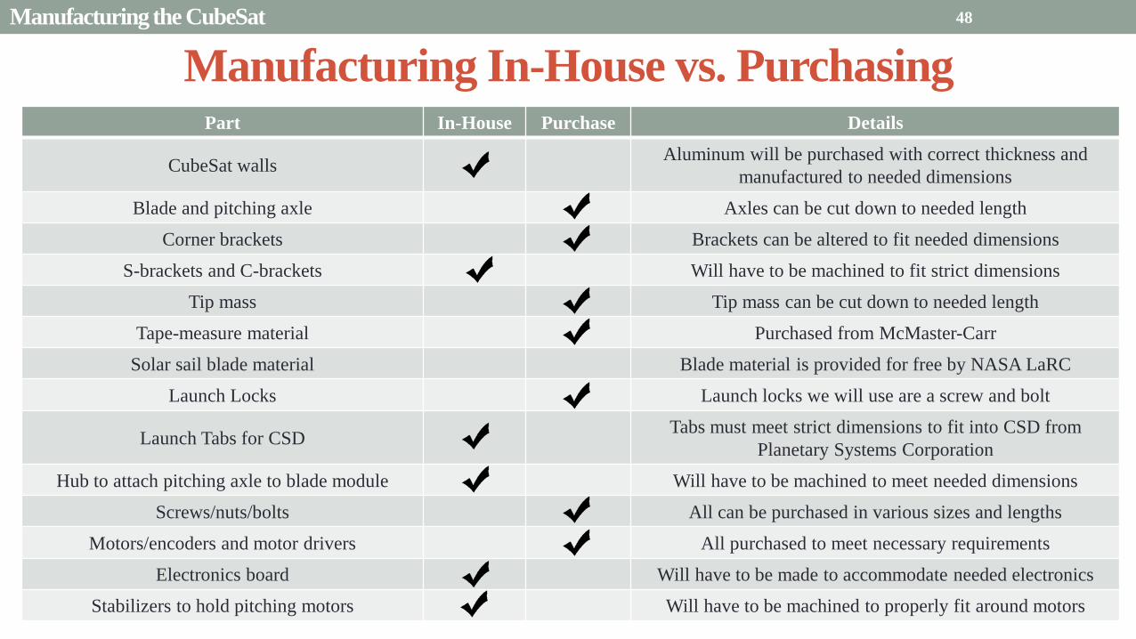
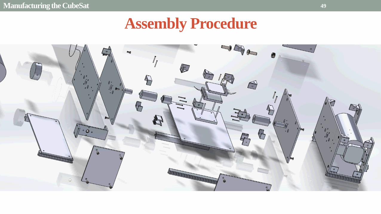
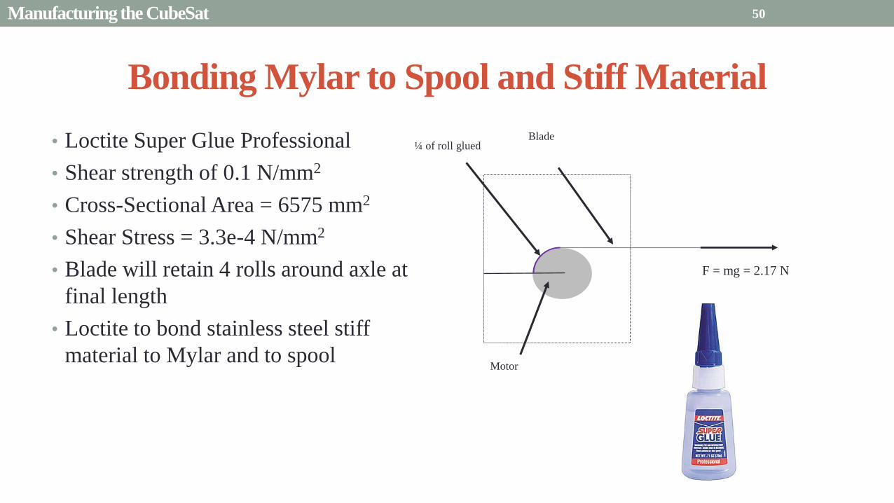
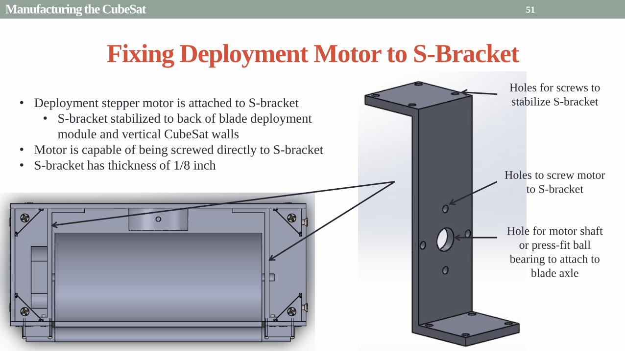
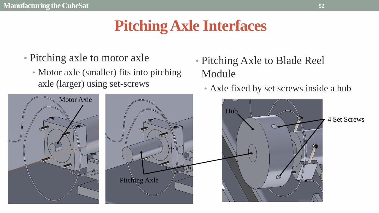
Presentation Sections
bull Purpose and Objectives
bull GHOST design solution
bull Critical Project Elements
bull Requirement Satisfaction
bull Controlled Deployment Rate
bull Pitching
bull Survive Launch
bull ElectronicSoftware Integration
bull Manufacturing the CubeSat
bull Summary
bull Remaining Risks and Mitigations
bull Verification and Validation of Design
bull Schedule and remaining work
53
Requirements Satisfaction
Aspect Requirement GHOST Specification
Mass 1 kgU 288 kg
Volume lt= 12U 6U
Life Span 4 months Greater than 4 months
Space Applicable
While design does not need to be
space worthy it should be applicable
to being used in space
All components are picked for
realistic use in space with minimal
cost parts and increased life span
54 Summary
Requirements Satisfaction
Aspect Requirement GHOST Specification
Characteristic Acceleration ac ge 01 mms2 ac = 03868 mms2
Sail Aspect Ratio AR ge 1001 AR = 38931
Sail Deployment Speed 1 cms le 10cms ~5 cms
Pitching Range Ability to pitch blades plusmn 90deg Ability to pitch blades plusmn 90deg
Pitching Coordination Multiple blade coordination when
pitching
Can pitch both blades at once either to
same angle or opposite angles
55 Summary
Presentation Sections
bullPurpose and Objectives
bullGHOST Design Solution
bullCritical Project Elements
bullRequirement Satisfaction
bullRemaining Risks
bullVerification and Validation of Design
bullProject Planning
56
Design Risks
Severity
Likelihood Marginal Major
Often Pitch angle error root not
following tip
Occasional Power loss COMM loss
Structural survivability
pitching motor failure
Improbable Small tear in Mylar Deploy too fast stowage
and deployment of Mylar
Axle failure
launch fail
space dust
deployment motor failure
57 Remaining Risks
Logistical Risks
Severity
Likelihood Minor Marginal Major
Often Parts delayed due to US
Postal Service
Occasional Structural consultation
unavailable
Ball vibrations test is not
available machine parts
not done on schedule
Government shutdown and
we canrsquot get Mylar or help
from NASA
Improbable No time for pitching test
High Bay in Fleming is
unavailable motors donrsquot
show up
58 Remaining Risks
Financial Risks
Severity
Likelihood Minor Marginal Major
Often Repurchase parts
Occasional Motor breaks Price of shake table
Improbable Hyper inflation
59 Remaining Risks
Presentation Sections
bullPurpose and Objectives
bullGHOST Design Solution
bullCritical Project Elements
bullRequirement Satisfaction
bullRemaining Risks
bullVerification and Validation of Design
bullProject Planning
60
Deployment System
Validate that the blade is deployed at a constant rate of 1-10 cms in a high bay
room
Verify that the motor can deploy at constant rate
Verify with test that the deployment system does not use more than the maximum power available of 10W
Validate that the blade can successfully deploy a blade with tape measure
material at a constant rate along ground
Verify with demonstration that the tape measure material can extend length of
blade
Verification and Validation
Verification and Validation
61
Blade Deployment Testing Information
bull Location Prof Frewrsquos High Bay Lab
bull Scheduled MarchApril with late night access to avoid
scheduling conflicts
bull Measurement Tape measure for distance and video
camera for time
bull Power Delivered 6253A Dual DC Power Supply
delivers 0-20 V and 0-3A
Tape measure
marking
distance up
wall
Kinematic Model
bull Torque from motor drives a constant velocity deployment
120591119898119900119905119900119903 = 120591119903119900119897119897 + 120591119901119906119904ℎ119894119899119892 119879119872 minus 120591119892119903119886119907119894119905119910 119879119872
120591119903119900119897119897 =119889119868119903119900119897119897
119889119905120596119903119900119897119897 + 119868119903119900119897119897
119889120596119903119900119897119897
119889119905
120591119901119906119904ℎ119894119899119892 119879119872 =119889119898119890119909119905
119889119905119903119903119900119897119897119907 + 119898119890119909119905
119889119903119903119900119897119897
119889119905119907
120591119892119903119886119907119894119905119910 119879119872 = 119898119890119909119905119903119903119900119897119897119892 bull 120649119945119952119949119941119946119951119944 = 120782 120782120790120787 N∙m 120649119950119952119941119942119949119950119938119961 = 120782 120782120782120789 N∙m
Power Supply
Verification and Validation
CubeSat Wire
62
Pitching System
Validate that the blade reel modules experience coordinated pitching
Verify that one blade reel module experiences periodic
motion
Verify that the blade reel module rotates to 0deg upon
initialization
Verify that the blade pitches to a given command
angle
Verify that the motorencoder system does not exceed power
available
Verification and Validation
Verification and Validation
63
Verify Pitching Angle Experiment Equipment and Specs
bull Use R60D RVIT (Rotary Variable Inductance Transducer) sensor to measure angles attaches to pin (red) in line with pitching axis bull Measures ranges of plusmn60deg rotation
bull Input Voltage = plusmn15 V
bull Output Voltage = plusmn75 V
bull Resolution = 0125 Vdeg
bull 119891119898119886119909 = 20 Hz
bull Use AD524 Precision Amplifier Instrumentation for signal conditioning bull Input Voltage plusmn10 V
bull Output Voltage plusmn10V
bull Requires Supply Voltage plusmn15
bull Use NI 9201 bull Input Voltage plusmn10 V
bull Has a USB output that can connect to a computer where vi program records
Experiment Set-Up
R60D RVIT
AD524
NI 9201 PC via USB
Verification and Validation 64
Verify Periodic Motion Experiment
bull Using the R60D RVIT set-up to measure deflection angles
bull With data of the angle deflection 120579 angular velocity 120596 and angular acceleration 120572 can be measured bull Motor restriction 120591119898119886119909 = 032 Nmiddotm
bull Model restriction 120596119898119886119909 = Ω2 if Ω = 2rpm 120596119898119886119909 = 02094 rads
Validation Model
bull R60D RVIT measures plusmn60deg deflection angles bull Critical condition blade reel module pitches plusmn90deg Ω=2rpm
bull 120572119888 = 00172 rads2 and 120596119898 = 0164 rads thus 120591119898 = 0083 mNmiddotm (119868119898119900119889 = 00048 kgmiddotm2)
120579 119905 120596 119905 120572 119905
Verification and Validation 65
Verification and Validation
Structural System
Validate that the final design can survive launch by using a shake
table
Verify the structural integrity by demonstrating that all stationary parts are
static
Verification and Validation 66
Trade Study FEM vs Vibration Table
Cost Time Experience
Similar to
Actual
Launch
Guaranteed Can
Do Total
FEM 4 1 1 3 4 215
Vibration
Table 2 3 4 4 2 32
Weight () 5 30 25 20 20 100
67 Verification and Validation
See Appendix for Full Trade Study
Validate Structural Stability
bull Will use a shaker table from Ball Aerospace
bull Cost = $250hr
bull Schedule Time to be determined in April
bull Specifications Peak vibration occurs with 34g at
frequency of 16 Hz (Saturn V)
bull Will be verified by examining the structural integrity
of the manufacturing
Verification and Validation 68
CubeSat
Shake Table
Presentation Sections
bullPurpose and Objectives
bullGHOST Design Solution
bullCritical Project Elements
bullRequirement Satisfaction
bullRemaining Risks
bullVerification and Validation of Design
bullProject Planning
69
Organizational Chart
Mark
Dolezal
Emily
Proano
Lauren
Persons
Casey
Myers
Nicholas
Busbey
Taylor
Smith
Karynna
Tuan
Megan
Scheele
Project
Manager
Software
Lead
Electrical
Lead
Systems Test and
Safety
Manufacturing
Lead Mechanics
Lead
CFO and
Materials
Lead
Organizing
team
meetings
Supporting
other leads
Non CPE
Tasks
Deployment
Control
Pitching
Control Motors and
Electronics
Power
Integrate
all system Perform
and Plan
tests
Manufacture
all in-house
parts
SolidWorks
Keep track
of financial
spending
Right
materials
are being
utilized
CubeSat
Assembly
Specific
System
Requirements
70 Project Planning
GHOST
Materials Mechanical Electrical Software Documents
Shake Table
Vibration
Analysis
Mechanical
Layout
Power Budget Pitch Control
Algorithm
Deployment
Rate Control
Algorithm SolidWorks
Model
Electrical
Wiring Layout
Thermodynamic
Analysis of
Electronic System
Mass Budget
Prototype of
CubeSat Bus
Motor
Subsystem
CDR
FFR
Spring
Schedule
Financial
Budget
Work Breakdown Structure (WBS)
Mylar from
NASA
Spin Up
Algorithm
Emergency
StopRestart System
71 Project Planning
PCB Design
Spring
Documents
113 120 127 203 210 217 224 303 310 317 324 331 407 414 421 428
MSR TRR SFR PFR
Time (date)
Purchase
motorsdrivers
Preliminary code
Electronic
integration
Test code
Electronicscode
interface
Purchase
raw materials
Manufacture frame
Assemble bus
Manufacture
remaining parts
Integrate system
Deployment test
Pitching test
Vibration test
Ta
sks
72
GHOST Spring Schedule
Project Planning
Planned Uncertainty
Key
Test Plan Test Scheduled Facility Specialized Equipment
Verify Pitch Angle 317 ITLL R60D RVIT NI 9201 AD524 Oscilloscope bench
power source
Zero Pitch Angle 317 ITLL R60D RVIT NI 9201 AD524 Oscilloscope bench
power source
Measure power used in
pitchdeployment 317 ITLL Ammeter voltmeter bench power source
Verify constant deployment 324 ITLL Firewire camera bench power source
ASEN2003BallTrackervi
Verify periodic motion 324 ITLL R60D RVIT NI 9201 AD524 Oscilloscope bench
power source
Validate tape measure ground
deployment 331 ITLL
Bench power source tape measure stop watch rollers
for tip mass
Validate coordinated pitching 331 ITLL R60D RVIT NI 9201 AD524 oscilloscope bench
power source
Validate 1g blade deployment 331-414 Prof Frew
high bay
Portable 6253A Dual DC Power Supply ladder tape
measure video camera
Validate launch ready 414 Ball Aero Shake Table
Project Planning 73
Cost Table ndash Structural Components
Part Price per
part NeededVolume Needed Total Price Supplier
Aluminum 6061 Sheet
(18rdquo thick) $ 8976 2ft times 2ft times 18 in $ 8976 The Metals Depot
Aluminum 6061 rod
(14 in diameter) $280 2 ft $280 The Metals Depot
Aluminum6061 rod
(716 in diameter) $494 2 ft $494 The Metals Depot
Steel Corner Brackets
(34rdquo times 12rdquo)
$197 4
braces 16 $788 Home Depot
Hardened 302 Stainless
Steel $3300 2 cm times 5 m times 127 microm $3300 McMaster-Carr
Total $11834
74 Project Planning
Cost Table ndash Electrical Components
Part Price per
part Needed Total Price Supplier
Sanyo Stepper Motor $ 5995 2 $11990 Pololu Electronics and Robotics
DRV8834 Low-Voltage Stepper
Motor Driver $995 2 $1990 Pololu Electronics and Robotics
FAULHABER 2036 BLDC
Servo Motor $23000 2 $46000 MicroMo Micro Motion Solutions
Atmel ATA6832-DK Brushless
DC Motor Controller $20800 2 $41600 Atmel
Encoder AU-ZSD1000A $22500 2 $45000 MicroMo Micro Motion Solutions
PIC18F87K22 Microcontroller $500 1 $500 Microchip
AD-524 Signal Converter $1767 1 $1767 Agilent
Total $148847
75 Project Planning
Questions
76
References
bull wwwloctiteproductscom
bull Vallado D A Fundamentals of Astrodynamics and Applications
bull Guerrant D Lawrence D Heaton A Earth Escape Capabilities of the Heliogyro Sail AIAA Paper
bull wwwspaceflightnowcom
bull Guerrant D HGVizGuim MATLAB Program
bull httpwwwmicromocombrushless-dc-motorsaspx
bull httpwwwfaulhabercomservletcomitmrwawservletAnzeigefremdaufruf=jaampkdid=40929ampsprachid=1amphtdigurl=n169933i95222html
bull httpwwwpololucom
bull httpasmmatwebcomsearchSpecificMaterialaspbassnum=MA6061t6
bull httpwwwruagcomthermalSpace_Thermal_HardwareMulti_Layer_Insulation
bull Helgesen Bryan Sierra Nevada Corporation
77
GyroSail Launch Configuration and Deployment Sequence
78
1 Launch configuration (6U) 2 Blade reel modules pitch to zero Fits within a 6U or 12U dispenser
3 PV arrays deploy
Other array configurations are possible
williamkwilkienasagov NASA PREDECISIONAL - FOR DISCUSSION PURPOSES ONLY
78 Appendix
GyroSail Primary Bus Systems Based on modified JPLU MichUCLACal PolyUT INSPIRE bus
williamkwilkienasagov
05U cold gas thruster ACS for detumbling
and initial spin-up
(httpwwwaustinsatnet)
05U EPS battery CampDH UHF backup
comms (U Mich) 05U DSN-compatible X-band
communications (JPL)
05U COTS star trackerimager ADC (BCT) sail
module processor (CU)
Klesh A et al 2013 ldquoINSPIRE Interplanetary NanoSpacecraft Pathfinder In Relevant Environmentrdquo Proceedings of the AIAAUSU Conference on Small Satellites Around the Corner SSC13-
XI-8 httpdigitalcommonsusuedusmallsat2013all2013127
NASA PREDECISIONAL - FOR DISCUSSION PURPOSES ONLY
79 Appendix
COMM Subsystem
bull 18 m Ka-band antennas at White
Sands New Mexico
bull Goddard Space Flight Center
Greebelt Maryland USA
supplied the Mulemba Space
Center in Angola
80 Appendix
Orion Crew
Module
6U Canisterized Satellite
Dispenser (CSD) ESPA Ring
Spacecraft
Adapter
Interim Cryogenic Propulsion
Stage (ICPS)
Secondary Payload Attachment to SLS
The SLS design is currently going through CDR An ESPA
ring is not currently in place but is mentioned in the SLS
CONOPS in order to accommodate secondary payloads
81 Appendix
Max Thrust Condition Collective 90deg pitch profile
Max thrust normal to orbital plane
(Halo orbits orbital plane rotation ie
inclination change)
82
Credit to Dan Guerrant
Appendix
Max Thrust Condition
F vs β M vs β
83
Credit to Dan Guerrant
Appendix
No Thrust Condition Collective 0deg pitch profile
Zero thrust
84
Credit to Dan Guerrant
Appendix
No Thrust Condition
F vs β M vs β
85
Credit to Dan Guerrant
Appendix
Max Torque Condition Collective 35deg pitch profile
Max torque used for spinning up sc
(opposite orientation for despinning)
86
Credit to Dan Guerrant
Appendix
Max Torque Condition
F vs β M vs β
87
Credit to Dan Guerrant
Appendix
Max In-Plane Thrust Condition Cyclic 35deg pitch profile
Max thrust in in-plane (d2) direction for orbit raising
88
Credit to Dan Guerrant
Appendix
Max In-Plane Thrust Condition
F vs β M vs β
89
Credit to Dan Guerrant
Appendix
Orbit Raising
F
90 Appendix
Thermal Space Concerns
bull Material Concerns
bull Aluminum 6061 -196 degC to 160deg C
bull Electronics Concerns
bull Typical Operating Temperature -55 to 80 degC
bull Countermeasures
bull Multi-layer Insulation AAErotherm S10-190
bull (0005 ndash 0035 Wm2K)
bull Battery operated heaters for pre-sail deployment
Multi-layer Insulation
Layer 1 1 x Outer layer
Layer 2 8 x 03 mil VDAPolyimideVDA perf
8 x Woven Polyester netting
Layer 3 1 x Outer layer
Layer 4 1 x Woven Polyester netting
91 Appendix
Rolled Up Blade Reel Calculation Optimal Sail Length 545 m ndash Sail chord of 14 cm
Max Diameter of Spool 598 cm
Diameter of Axle 05 cm
Length of Stiff Material 5 m
Dimension of Stiff Material 5 m times 2 cm times 127 microm
92 Appendix
Torque calculation
bull Note current calculated via T=kI (where T is torque I is amp k is the torque
constant specific to the motor)
T = kI
(k = 005 NmA)
93 Appendix
Servo Controller
94 Appendix
Encoder Dimensions and Interface
bull FAULHABER IE2-1024
95 Appendix
Stepper Motor Torque
96 Appendix
Motor Phases (Stepper)
97 Appendix
98 Appendix
99 Appendix
100 Appendix
101 Appendix
Microcontroller
102 Appendix
ATA6832 Phase Output Chip
103 Appendix
ATA6624 Bypassed Chip
bull Bypassed chip
on servo controller
104 Appendix
Power Budget
105 Appendix
Wire Gauge
bull Stepper Motor 26AWG (04 mm diameter)
bull Servomotor 24 AWG (051 mm diameter)
bull Encoder 24 AWG
Voltage Drop () AWG Max Gauge
001 5
01 15
1 25
5 32
NOTE Voltage drop calculated at 1A and 40 cm of wire
106
24 AWG Wire
Appendix
Trade Study ndash FEM vs Vibration Table
Factor 4 3 2 1
Cost No money 0 gt C gt $100 $100 gt C gt $300 $300 lt C
Time 0 min lt T lt 30 min 30 min lt T lt 2 hrs 2 hrs lt T lt 1 day 1day lt T
Experience Everyone has
experience
A couple people
know how to
1 person has
experience
No one has
experience
Similar To Actual
Launch Simulate real launch
Doesnrsquot have all
variables experienced
Has only a couple
similarities
No similarities to
launch
Guaranteed Can Do
Donrsquot need any
outside equipment or
help
Need outside
equipment but
guaranteed use
Need outside
equipment but own
work at higher
priority
Need outside
equipment but canrsquot
use
Scoring
107 Appendix
Weighting
Weight () Category Reasoning
5 Cost Have a lot of extra $ in the budget
30 Time Have a strict schedule but not a main focus of the
project
25 Experience If no one has experience it will take a lot of time
20 Similar to Actual Launch Needs to be like actual launch
20 Guaranteed Can Do Needs to be able to accomplish but not the most
important focus
108 Appendix
Finite Element Method (FEM)
Objectives Description ProCon
Cost No money because one of us
would do it Pro
Time A lot of time to learn and then
perform FEM Con
Experience No one in group has FEM
experience Con
Similar to Actual Launch Very similar to actual launch Pro
Guaranteed Can Do All we need is paper pen and
theory to do Pro
109 Appendix
Vibration Table
Objective Description ProCons
Cost $250hr Con
Time A hour on the table should simulate
launch Pro
Experience Donrsquot need experience to run
vibration table Pro
Similar to Actual Launch Actually putting our system through
vibration stress Pro
Guaranteed Can Do No guarantee but most likely can Con
110 Appendix
SpinUp State
1 Check value of SpinUp to see if satellite is already spun up
bull Continue if satellite is not already spun-up
2 Deploy the tape stiffened length of the blade
3 Pitch to the spin up angle
4 Wait until characteristic angular velocity is reached
5 Pitch to pre-deployment position
6 Save SpinUp as completed
Appendix 111
Deployment State
1 Check if satellite has been spun up yet
bull Continue if it has
2 Check if blades are already deployed
bull Continue if they havenrsquot
3 Run deploy algorithm until blades are fully deployed
4 Save value saying blades have been deployed
Appendix 112
Pitching State
1 Check if satellite has been spun up
bull Continue if satellite has been spun up
2 Check if blades have been deployed
bull Continue if blades have been deployed
3 Look at commanded pitch profile
4 Find correlated sinusoid command
5 Command servo to pitch angle for the time in the orbit
6 Continue until given a new pitch command
Appendix 113
Emergency Stop
1 Save which state was interrupted
2 Save last position in interrupted
state
3 Wait until Restart command is
received
1 Check two previous states to see
what is being restarted
2 Look at saved last position in
state being restarted
3 Adapt the algorithm of the state
to continue where left off
Restart
Appendix 114
Comparison with Previous Heliogyro Concepts MIT (1989) NASA (2011) GHOST
Total sail craft mass (kg) 18 84
288 (6)
Characteristic acceleration ac
(mms2) 06 10 03868 (01854)
Sail reflective area (m2) 1200 960 1526
Non-sail mass (kg) 5 5 --
Number of sail blades 8 6 2
Blade chord (m) 15 08 014
Blade length (m) 100 200 545
Rotational period (minutes) 3 3 1
Blade root stress (Pa) 8650 34000 --
Blade root allowable stress (Pa) 55 M 55 M --
Blade root tension load (N) 01 007 --
115 Appendix
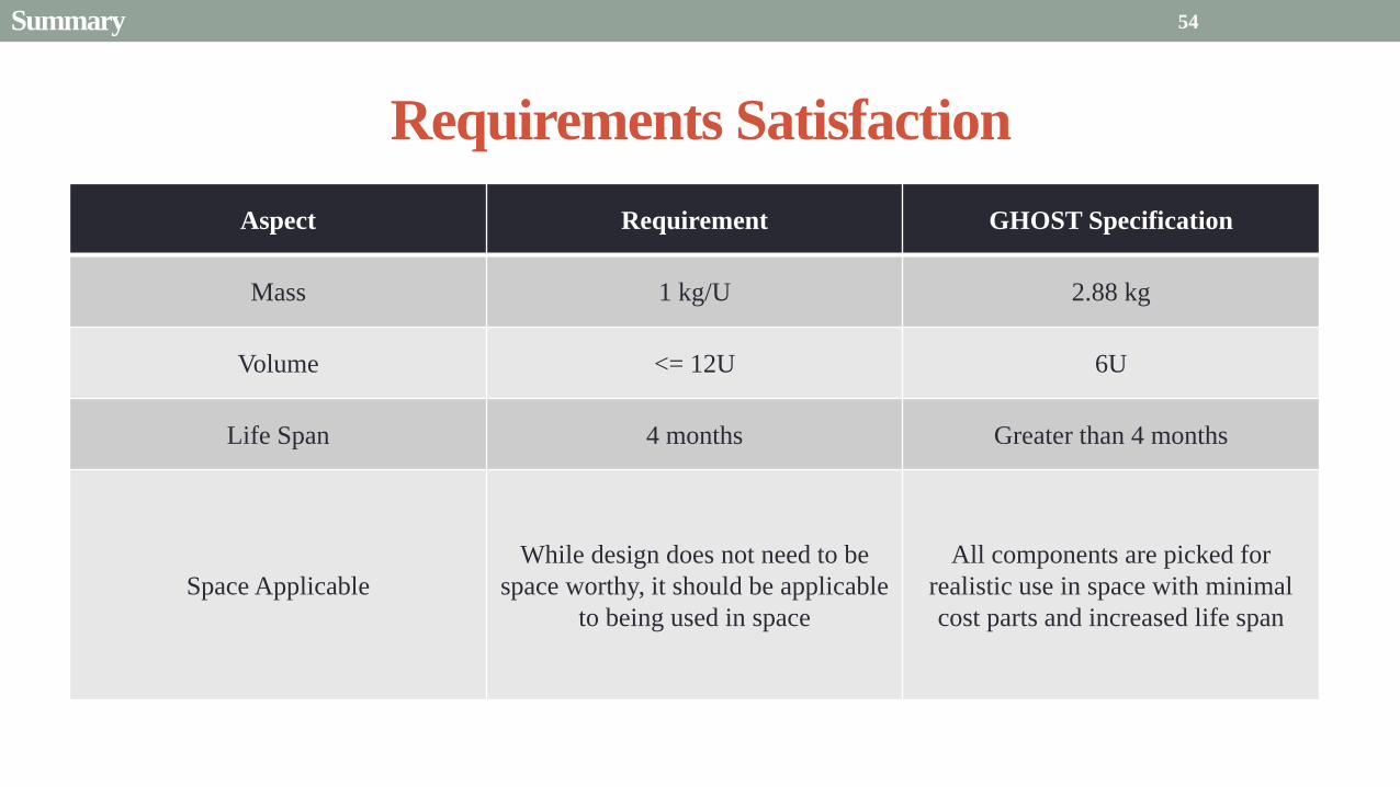
Requirements Satisfaction
Aspect Requirement GHOST Specification
Mass 1 kgU 288 kg
Volume lt= 12U 6U
Life Span 4 months Greater than 4 months
Space Applicable
While design does not need to be
space worthy it should be applicable
to being used in space
All components are picked for
realistic use in space with minimal
cost parts and increased life span
54 Summary
Requirements Satisfaction
Aspect Requirement GHOST Specification
Characteristic Acceleration ac ge 01 mms2 ac = 03868 mms2
Sail Aspect Ratio AR ge 1001 AR = 38931
Sail Deployment Speed 1 cms le 10cms ~5 cms
Pitching Range Ability to pitch blades plusmn 90deg Ability to pitch blades plusmn 90deg
Pitching Coordination Multiple blade coordination when
pitching
Can pitch both blades at once either to
same angle or opposite angles
55 Summary
Presentation Sections
bullPurpose and Objectives
bullGHOST Design Solution
bullCritical Project Elements
bullRequirement Satisfaction
bullRemaining Risks
bullVerification and Validation of Design
bullProject Planning
56
Design Risks
Severity
Likelihood Marginal Major
Often Pitch angle error root not
following tip
Occasional Power loss COMM loss
Structural survivability
pitching motor failure
Improbable Small tear in Mylar Deploy too fast stowage
and deployment of Mylar
Axle failure
launch fail
space dust
deployment motor failure
57 Remaining Risks
Logistical Risks
Severity
Likelihood Minor Marginal Major
Often Parts delayed due to US
Postal Service
Occasional Structural consultation
unavailable
Ball vibrations test is not
available machine parts
not done on schedule
Government shutdown and
we canrsquot get Mylar or help
from NASA
Improbable No time for pitching test
High Bay in Fleming is
unavailable motors donrsquot
show up
58 Remaining Risks
Financial Risks
Severity
Likelihood Minor Marginal Major
Often Repurchase parts
Occasional Motor breaks Price of shake table
Improbable Hyper inflation
59 Remaining Risks
Presentation Sections
bullPurpose and Objectives
bullGHOST Design Solution
bullCritical Project Elements
bullRequirement Satisfaction
bullRemaining Risks
bullVerification and Validation of Design
bullProject Planning
60
Deployment System
Validate that the blade is deployed at a constant rate of 1-10 cms in a high bay
room
Verify that the motor can deploy at constant rate
Verify with test that the deployment system does not use more than the maximum power available of 10W
Validate that the blade can successfully deploy a blade with tape measure
material at a constant rate along ground
Verify with demonstration that the tape measure material can extend length of
blade
Verification and Validation
Verification and Validation
61
Blade Deployment Testing Information
bull Location Prof Frewrsquos High Bay Lab
bull Scheduled MarchApril with late night access to avoid
scheduling conflicts
bull Measurement Tape measure for distance and video
camera for time
bull Power Delivered 6253A Dual DC Power Supply
delivers 0-20 V and 0-3A
Tape measure
marking
distance up
wall
Kinematic Model
bull Torque from motor drives a constant velocity deployment
120591119898119900119905119900119903 = 120591119903119900119897119897 + 120591119901119906119904ℎ119894119899119892 119879119872 minus 120591119892119903119886119907119894119905119910 119879119872
120591119903119900119897119897 =119889119868119903119900119897119897
119889119905120596119903119900119897119897 + 119868119903119900119897119897
119889120596119903119900119897119897
119889119905
120591119901119906119904ℎ119894119899119892 119879119872 =119889119898119890119909119905
119889119905119903119903119900119897119897119907 + 119898119890119909119905
119889119903119903119900119897119897
119889119905119907
120591119892119903119886119907119894119905119910 119879119872 = 119898119890119909119905119903119903119900119897119897119892 bull 120649119945119952119949119941119946119951119944 = 120782 120782120790120787 N∙m 120649119950119952119941119942119949119950119938119961 = 120782 120782120782120789 N∙m
Power Supply
Verification and Validation
CubeSat Wire
62
Pitching System
Validate that the blade reel modules experience coordinated pitching
Verify that one blade reel module experiences periodic
motion
Verify that the blade reel module rotates to 0deg upon
initialization
Verify that the blade pitches to a given command
angle
Verify that the motorencoder system does not exceed power
available
Verification and Validation
Verification and Validation
63
Verify Pitching Angle Experiment Equipment and Specs
bull Use R60D RVIT (Rotary Variable Inductance Transducer) sensor to measure angles attaches to pin (red) in line with pitching axis bull Measures ranges of plusmn60deg rotation
bull Input Voltage = plusmn15 V
bull Output Voltage = plusmn75 V
bull Resolution = 0125 Vdeg
bull 119891119898119886119909 = 20 Hz
bull Use AD524 Precision Amplifier Instrumentation for signal conditioning bull Input Voltage plusmn10 V
bull Output Voltage plusmn10V
bull Requires Supply Voltage plusmn15
bull Use NI 9201 bull Input Voltage plusmn10 V
bull Has a USB output that can connect to a computer where vi program records
Experiment Set-Up
R60D RVIT
AD524
NI 9201 PC via USB
Verification and Validation 64
Verify Periodic Motion Experiment
bull Using the R60D RVIT set-up to measure deflection angles
bull With data of the angle deflection 120579 angular velocity 120596 and angular acceleration 120572 can be measured bull Motor restriction 120591119898119886119909 = 032 Nmiddotm
bull Model restriction 120596119898119886119909 = Ω2 if Ω = 2rpm 120596119898119886119909 = 02094 rads
Validation Model
bull R60D RVIT measures plusmn60deg deflection angles bull Critical condition blade reel module pitches plusmn90deg Ω=2rpm
bull 120572119888 = 00172 rads2 and 120596119898 = 0164 rads thus 120591119898 = 0083 mNmiddotm (119868119898119900119889 = 00048 kgmiddotm2)
120579 119905 120596 119905 120572 119905
Verification and Validation 65
Verification and Validation
Structural System
Validate that the final design can survive launch by using a shake
table
Verify the structural integrity by demonstrating that all stationary parts are
static
Verification and Validation 66
Trade Study FEM vs Vibration Table
Cost Time Experience
Similar to
Actual
Launch
Guaranteed Can
Do Total
FEM 4 1 1 3 4 215
Vibration
Table 2 3 4 4 2 32
Weight () 5 30 25 20 20 100
67 Verification and Validation
See Appendix for Full Trade Study
Validate Structural Stability
bull Will use a shaker table from Ball Aerospace
bull Cost = $250hr
bull Schedule Time to be determined in April
bull Specifications Peak vibration occurs with 34g at
frequency of 16 Hz (Saturn V)
bull Will be verified by examining the structural integrity
of the manufacturing
Verification and Validation 68
CubeSat
Shake Table
Presentation Sections
bullPurpose and Objectives
bullGHOST Design Solution
bullCritical Project Elements
bullRequirement Satisfaction
bullRemaining Risks
bullVerification and Validation of Design
bullProject Planning
69
Organizational Chart
Mark
Dolezal
Emily
Proano
Lauren
Persons
Casey
Myers
Nicholas
Busbey
Taylor
Smith
Karynna
Tuan
Megan
Scheele
Project
Manager
Software
Lead
Electrical
Lead
Systems Test and
Safety
Manufacturing
Lead Mechanics
Lead
CFO and
Materials
Lead
Organizing
team
meetings
Supporting
other leads
Non CPE
Tasks
Deployment
Control
Pitching
Control Motors and
Electronics
Power
Integrate
all system Perform
and Plan
tests
Manufacture
all in-house
parts
SolidWorks
Keep track
of financial
spending
Right
materials
are being
utilized
CubeSat
Assembly
Specific
System
Requirements
70 Project Planning
GHOST
Materials Mechanical Electrical Software Documents
Shake Table
Vibration
Analysis
Mechanical
Layout
Power Budget Pitch Control
Algorithm
Deployment
Rate Control
Algorithm SolidWorks
Model
Electrical
Wiring Layout
Thermodynamic
Analysis of
Electronic System
Mass Budget
Prototype of
CubeSat Bus
Motor
Subsystem
CDR
FFR
Spring
Schedule
Financial
Budget
Work Breakdown Structure (WBS)
Mylar from
NASA
Spin Up
Algorithm
Emergency
StopRestart System
71 Project Planning
PCB Design
Spring
Documents
113 120 127 203 210 217 224 303 310 317 324 331 407 414 421 428
MSR TRR SFR PFR
Time (date)
Purchase
motorsdrivers
Preliminary code
Electronic
integration
Test code
Electronicscode
interface
Purchase
raw materials
Manufacture frame
Assemble bus
Manufacture
remaining parts
Integrate system
Deployment test
Pitching test
Vibration test
Ta
sks
72
GHOST Spring Schedule
Project Planning
Planned Uncertainty
Key
Test Plan Test Scheduled Facility Specialized Equipment
Verify Pitch Angle 317 ITLL R60D RVIT NI 9201 AD524 Oscilloscope bench
power source
Zero Pitch Angle 317 ITLL R60D RVIT NI 9201 AD524 Oscilloscope bench
power source
Measure power used in
pitchdeployment 317 ITLL Ammeter voltmeter bench power source
Verify constant deployment 324 ITLL Firewire camera bench power source
ASEN2003BallTrackervi
Verify periodic motion 324 ITLL R60D RVIT NI 9201 AD524 Oscilloscope bench
power source
Validate tape measure ground
deployment 331 ITLL
Bench power source tape measure stop watch rollers
for tip mass
Validate coordinated pitching 331 ITLL R60D RVIT NI 9201 AD524 oscilloscope bench
power source
Validate 1g blade deployment 331-414 Prof Frew
high bay
Portable 6253A Dual DC Power Supply ladder tape
measure video camera
Validate launch ready 414 Ball Aero Shake Table
Project Planning 73
Cost Table ndash Structural Components
Part Price per
part NeededVolume Needed Total Price Supplier
Aluminum 6061 Sheet
(18rdquo thick) $ 8976 2ft times 2ft times 18 in $ 8976 The Metals Depot
Aluminum 6061 rod
(14 in diameter) $280 2 ft $280 The Metals Depot
Aluminum6061 rod
(716 in diameter) $494 2 ft $494 The Metals Depot
Steel Corner Brackets
(34rdquo times 12rdquo)
$197 4
braces 16 $788 Home Depot
Hardened 302 Stainless
Steel $3300 2 cm times 5 m times 127 microm $3300 McMaster-Carr
Total $11834
74 Project Planning
Cost Table ndash Electrical Components
Part Price per
part Needed Total Price Supplier
Sanyo Stepper Motor $ 5995 2 $11990 Pololu Electronics and Robotics
DRV8834 Low-Voltage Stepper
Motor Driver $995 2 $1990 Pololu Electronics and Robotics
FAULHABER 2036 BLDC
Servo Motor $23000 2 $46000 MicroMo Micro Motion Solutions
Atmel ATA6832-DK Brushless
DC Motor Controller $20800 2 $41600 Atmel
Encoder AU-ZSD1000A $22500 2 $45000 MicroMo Micro Motion Solutions
PIC18F87K22 Microcontroller $500 1 $500 Microchip
AD-524 Signal Converter $1767 1 $1767 Agilent
Total $148847
75 Project Planning
Questions
76
References
bull wwwloctiteproductscom
bull Vallado D A Fundamentals of Astrodynamics and Applications
bull Guerrant D Lawrence D Heaton A Earth Escape Capabilities of the Heliogyro Sail AIAA Paper
bull wwwspaceflightnowcom
bull Guerrant D HGVizGuim MATLAB Program
bull httpwwwmicromocombrushless-dc-motorsaspx
bull httpwwwfaulhabercomservletcomitmrwawservletAnzeigefremdaufruf=jaampkdid=40929ampsprachid=1amphtdigurl=n169933i95222html
bull httpwwwpololucom
bull httpasmmatwebcomsearchSpecificMaterialaspbassnum=MA6061t6
bull httpwwwruagcomthermalSpace_Thermal_HardwareMulti_Layer_Insulation
bull Helgesen Bryan Sierra Nevada Corporation
77
GyroSail Launch Configuration and Deployment Sequence
78
1 Launch configuration (6U) 2 Blade reel modules pitch to zero Fits within a 6U or 12U dispenser
3 PV arrays deploy
Other array configurations are possible
williamkwilkienasagov NASA PREDECISIONAL - FOR DISCUSSION PURPOSES ONLY
78 Appendix
GyroSail Primary Bus Systems Based on modified JPLU MichUCLACal PolyUT INSPIRE bus
williamkwilkienasagov
05U cold gas thruster ACS for detumbling
and initial spin-up
(httpwwwaustinsatnet)
05U EPS battery CampDH UHF backup
comms (U Mich) 05U DSN-compatible X-band
communications (JPL)
05U COTS star trackerimager ADC (BCT) sail
module processor (CU)
Klesh A et al 2013 ldquoINSPIRE Interplanetary NanoSpacecraft Pathfinder In Relevant Environmentrdquo Proceedings of the AIAAUSU Conference on Small Satellites Around the Corner SSC13-
XI-8 httpdigitalcommonsusuedusmallsat2013all2013127
NASA PREDECISIONAL - FOR DISCUSSION PURPOSES ONLY
79 Appendix
COMM Subsystem
bull 18 m Ka-band antennas at White
Sands New Mexico
bull Goddard Space Flight Center
Greebelt Maryland USA
supplied the Mulemba Space
Center in Angola
80 Appendix
Orion Crew
Module
6U Canisterized Satellite
Dispenser (CSD) ESPA Ring
Spacecraft
Adapter
Interim Cryogenic Propulsion
Stage (ICPS)
Secondary Payload Attachment to SLS
The SLS design is currently going through CDR An ESPA
ring is not currently in place but is mentioned in the SLS
CONOPS in order to accommodate secondary payloads
81 Appendix
Max Thrust Condition Collective 90deg pitch profile
Max thrust normal to orbital plane
(Halo orbits orbital plane rotation ie
inclination change)
82
Credit to Dan Guerrant
Appendix
Max Thrust Condition
F vs β M vs β
83
Credit to Dan Guerrant
Appendix
No Thrust Condition Collective 0deg pitch profile
Zero thrust
84
Credit to Dan Guerrant
Appendix
No Thrust Condition
F vs β M vs β
85
Credit to Dan Guerrant
Appendix
Max Torque Condition Collective 35deg pitch profile
Max torque used for spinning up sc
(opposite orientation for despinning)
86
Credit to Dan Guerrant
Appendix
Max Torque Condition
F vs β M vs β
87
Credit to Dan Guerrant
Appendix
Max In-Plane Thrust Condition Cyclic 35deg pitch profile
Max thrust in in-plane (d2) direction for orbit raising
88
Credit to Dan Guerrant
Appendix
Max In-Plane Thrust Condition
F vs β M vs β
89
Credit to Dan Guerrant
Appendix
Orbit Raising
F
90 Appendix
Thermal Space Concerns
bull Material Concerns
bull Aluminum 6061 -196 degC to 160deg C
bull Electronics Concerns
bull Typical Operating Temperature -55 to 80 degC
bull Countermeasures
bull Multi-layer Insulation AAErotherm S10-190
bull (0005 ndash 0035 Wm2K)
bull Battery operated heaters for pre-sail deployment
Multi-layer Insulation
Layer 1 1 x Outer layer
Layer 2 8 x 03 mil VDAPolyimideVDA perf
8 x Woven Polyester netting
Layer 3 1 x Outer layer
Layer 4 1 x Woven Polyester netting
91 Appendix
Rolled Up Blade Reel Calculation Optimal Sail Length 545 m ndash Sail chord of 14 cm
Max Diameter of Spool 598 cm
Diameter of Axle 05 cm
Length of Stiff Material 5 m
Dimension of Stiff Material 5 m times 2 cm times 127 microm
92 Appendix
Torque calculation
bull Note current calculated via T=kI (where T is torque I is amp k is the torque
constant specific to the motor)
T = kI
(k = 005 NmA)
93 Appendix
Servo Controller
94 Appendix
Encoder Dimensions and Interface
bull FAULHABER IE2-1024
95 Appendix
Stepper Motor Torque
96 Appendix
Motor Phases (Stepper)
97 Appendix
98 Appendix
99 Appendix
100 Appendix
101 Appendix
Microcontroller
102 Appendix
ATA6832 Phase Output Chip
103 Appendix
ATA6624 Bypassed Chip
bull Bypassed chip
on servo controller
104 Appendix
Power Budget
105 Appendix
Wire Gauge
bull Stepper Motor 26AWG (04 mm diameter)
bull Servomotor 24 AWG (051 mm diameter)
bull Encoder 24 AWG
Voltage Drop () AWG Max Gauge
001 5
01 15
1 25
5 32
NOTE Voltage drop calculated at 1A and 40 cm of wire
106
24 AWG Wire
Appendix
Trade Study ndash FEM vs Vibration Table
Factor 4 3 2 1
Cost No money 0 gt C gt $100 $100 gt C gt $300 $300 lt C
Time 0 min lt T lt 30 min 30 min lt T lt 2 hrs 2 hrs lt T lt 1 day 1day lt T
Experience Everyone has
experience
A couple people
know how to
1 person has
experience
No one has
experience
Similar To Actual
Launch Simulate real launch
Doesnrsquot have all
variables experienced
Has only a couple
similarities
No similarities to
launch
Guaranteed Can Do
Donrsquot need any
outside equipment or
help
Need outside
equipment but
guaranteed use
Need outside
equipment but own
work at higher
priority
Need outside
equipment but canrsquot
use
Scoring
107 Appendix
Weighting
Weight () Category Reasoning
5 Cost Have a lot of extra $ in the budget
30 Time Have a strict schedule but not a main focus of the
project
25 Experience If no one has experience it will take a lot of time
20 Similar to Actual Launch Needs to be like actual launch
20 Guaranteed Can Do Needs to be able to accomplish but not the most
important focus
108 Appendix
Finite Element Method (FEM)
Objectives Description ProCon
Cost No money because one of us
would do it Pro
Time A lot of time to learn and then
perform FEM Con
Experience No one in group has FEM
experience Con
Similar to Actual Launch Very similar to actual launch Pro
Guaranteed Can Do All we need is paper pen and
theory to do Pro
109 Appendix
Vibration Table
Objective Description ProCons
Cost $250hr Con
Time A hour on the table should simulate
launch Pro
Experience Donrsquot need experience to run
vibration table Pro
Similar to Actual Launch Actually putting our system through
vibration stress Pro
Guaranteed Can Do No guarantee but most likely can Con
110 Appendix
SpinUp State
1 Check value of SpinUp to see if satellite is already spun up
bull Continue if satellite is not already spun-up
2 Deploy the tape stiffened length of the blade
3 Pitch to the spin up angle
4 Wait until characteristic angular velocity is reached
5 Pitch to pre-deployment position
6 Save SpinUp as completed
Appendix 111
Deployment State
1 Check if satellite has been spun up yet
bull Continue if it has
2 Check if blades are already deployed
bull Continue if they havenrsquot
3 Run deploy algorithm until blades are fully deployed
4 Save value saying blades have been deployed
Appendix 112
Pitching State
1 Check if satellite has been spun up
bull Continue if satellite has been spun up
2 Check if blades have been deployed
bull Continue if blades have been deployed
3 Look at commanded pitch profile
4 Find correlated sinusoid command
5 Command servo to pitch angle for the time in the orbit
6 Continue until given a new pitch command
Appendix 113
Emergency Stop
1 Save which state was interrupted
2 Save last position in interrupted
state
3 Wait until Restart command is
received
1 Check two previous states to see
what is being restarted
2 Look at saved last position in
state being restarted
3 Adapt the algorithm of the state
to continue where left off
Restart
Appendix 114
Comparison with Previous Heliogyro Concepts MIT (1989) NASA (2011) GHOST
Total sail craft mass (kg) 18 84
288 (6)
Characteristic acceleration ac
(mms2) 06 10 03868 (01854)
Sail reflective area (m2) 1200 960 1526
Non-sail mass (kg) 5 5 --
Number of sail blades 8 6 2
Blade chord (m) 15 08 014
Blade length (m) 100 200 545
Rotational period (minutes) 3 3 1
Blade root stress (Pa) 8650 34000 --
Blade root allowable stress (Pa) 55 M 55 M --
Blade root tension load (N) 01 007 --
115 Appendix
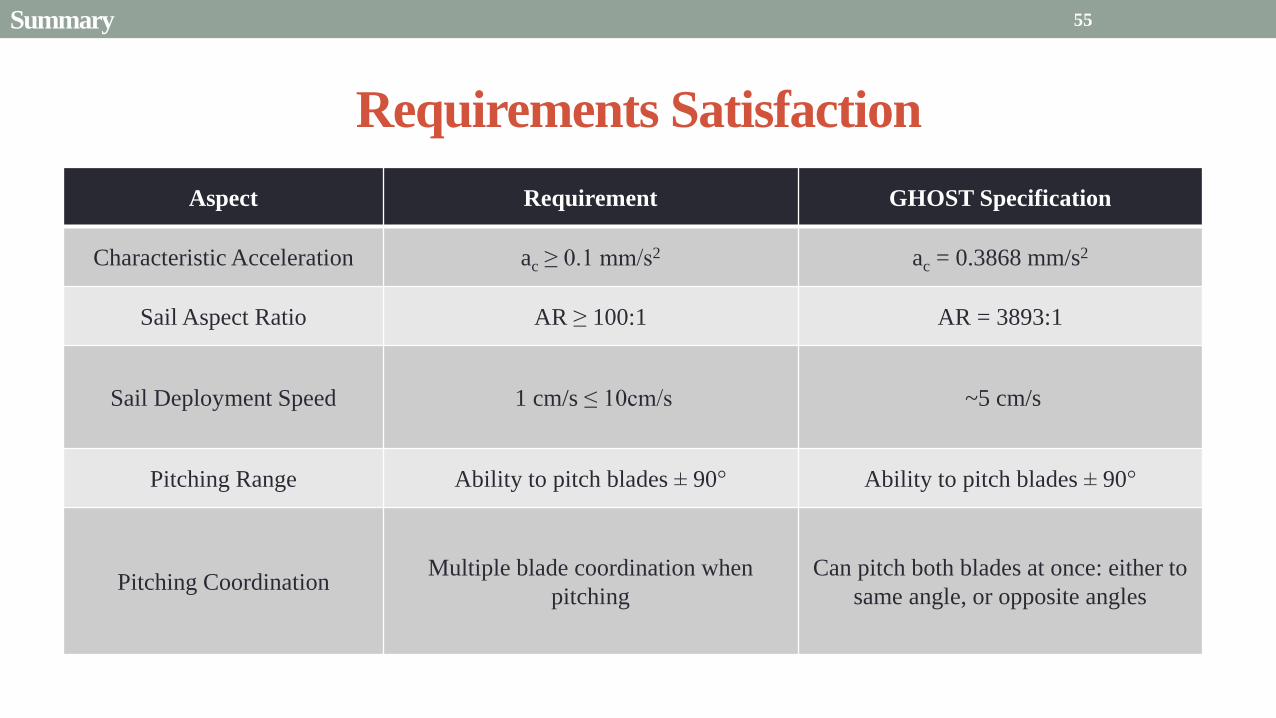
Requirements Satisfaction
Aspect Requirement GHOST Specification
Characteristic Acceleration ac ge 01 mms2 ac = 03868 mms2
Sail Aspect Ratio AR ge 1001 AR = 38931
Sail Deployment Speed 1 cms le 10cms ~5 cms
Pitching Range Ability to pitch blades plusmn 90deg Ability to pitch blades plusmn 90deg
Pitching Coordination Multiple blade coordination when
pitching
Can pitch both blades at once either to
same angle or opposite angles
55 Summary
Presentation Sections
bullPurpose and Objectives
bullGHOST Design Solution
bullCritical Project Elements
bullRequirement Satisfaction
bullRemaining Risks
bullVerification and Validation of Design
bullProject Planning
56
Design Risks
Severity
Likelihood Marginal Major
Often Pitch angle error root not
following tip
Occasional Power loss COMM loss
Structural survivability
pitching motor failure
Improbable Small tear in Mylar Deploy too fast stowage
and deployment of Mylar
Axle failure
launch fail
space dust
deployment motor failure
57 Remaining Risks
Logistical Risks
Severity
Likelihood Minor Marginal Major
Often Parts delayed due to US
Postal Service
Occasional Structural consultation
unavailable
Ball vibrations test is not
available machine parts
not done on schedule
Government shutdown and
we canrsquot get Mylar or help
from NASA
Improbable No time for pitching test
High Bay in Fleming is
unavailable motors donrsquot
show up
58 Remaining Risks
Financial Risks
Severity
Likelihood Minor Marginal Major
Often Repurchase parts
Occasional Motor breaks Price of shake table
Improbable Hyper inflation
59 Remaining Risks
Presentation Sections
bullPurpose and Objectives
bullGHOST Design Solution
bullCritical Project Elements
bullRequirement Satisfaction
bullRemaining Risks
bullVerification and Validation of Design
bullProject Planning
60
Deployment System
Validate that the blade is deployed at a constant rate of 1-10 cms in a high bay
room
Verify that the motor can deploy at constant rate
Verify with test that the deployment system does not use more than the maximum power available of 10W
Validate that the blade can successfully deploy a blade with tape measure
material at a constant rate along ground
Verify with demonstration that the tape measure material can extend length of
blade
Verification and Validation
Verification and Validation
61
Blade Deployment Testing Information
bull Location Prof Frewrsquos High Bay Lab
bull Scheduled MarchApril with late night access to avoid
scheduling conflicts
bull Measurement Tape measure for distance and video
camera for time
bull Power Delivered 6253A Dual DC Power Supply
delivers 0-20 V and 0-3A
Tape measure
marking
distance up
wall
Kinematic Model
bull Torque from motor drives a constant velocity deployment
120591119898119900119905119900119903 = 120591119903119900119897119897 + 120591119901119906119904ℎ119894119899119892 119879119872 minus 120591119892119903119886119907119894119905119910 119879119872
120591119903119900119897119897 =119889119868119903119900119897119897
119889119905120596119903119900119897119897 + 119868119903119900119897119897
119889120596119903119900119897119897
119889119905
120591119901119906119904ℎ119894119899119892 119879119872 =119889119898119890119909119905
119889119905119903119903119900119897119897119907 + 119898119890119909119905
119889119903119903119900119897119897
119889119905119907
120591119892119903119886119907119894119905119910 119879119872 = 119898119890119909119905119903119903119900119897119897119892 bull 120649119945119952119949119941119946119951119944 = 120782 120782120790120787 N∙m 120649119950119952119941119942119949119950119938119961 = 120782 120782120782120789 N∙m
Power Supply
Verification and Validation
CubeSat Wire
62
Pitching System
Validate that the blade reel modules experience coordinated pitching
Verify that one blade reel module experiences periodic
motion
Verify that the blade reel module rotates to 0deg upon
initialization
Verify that the blade pitches to a given command
angle
Verify that the motorencoder system does not exceed power
available
Verification and Validation
Verification and Validation
63
Verify Pitching Angle Experiment Equipment and Specs
bull Use R60D RVIT (Rotary Variable Inductance Transducer) sensor to measure angles attaches to pin (red) in line with pitching axis bull Measures ranges of plusmn60deg rotation
bull Input Voltage = plusmn15 V
bull Output Voltage = plusmn75 V
bull Resolution = 0125 Vdeg
bull 119891119898119886119909 = 20 Hz
bull Use AD524 Precision Amplifier Instrumentation for signal conditioning bull Input Voltage plusmn10 V
bull Output Voltage plusmn10V
bull Requires Supply Voltage plusmn15
bull Use NI 9201 bull Input Voltage plusmn10 V
bull Has a USB output that can connect to a computer where vi program records
Experiment Set-Up
R60D RVIT
AD524
NI 9201 PC via USB
Verification and Validation 64
Verify Periodic Motion Experiment
bull Using the R60D RVIT set-up to measure deflection angles
bull With data of the angle deflection 120579 angular velocity 120596 and angular acceleration 120572 can be measured bull Motor restriction 120591119898119886119909 = 032 Nmiddotm
bull Model restriction 120596119898119886119909 = Ω2 if Ω = 2rpm 120596119898119886119909 = 02094 rads
Validation Model
bull R60D RVIT measures plusmn60deg deflection angles bull Critical condition blade reel module pitches plusmn90deg Ω=2rpm
bull 120572119888 = 00172 rads2 and 120596119898 = 0164 rads thus 120591119898 = 0083 mNmiddotm (119868119898119900119889 = 00048 kgmiddotm2)
120579 119905 120596 119905 120572 119905
Verification and Validation 65
Verification and Validation
Structural System
Validate that the final design can survive launch by using a shake
table
Verify the structural integrity by demonstrating that all stationary parts are
static
Verification and Validation 66
Trade Study FEM vs Vibration Table
Cost Time Experience
Similar to
Actual
Launch
Guaranteed Can
Do Total
FEM 4 1 1 3 4 215
Vibration
Table 2 3 4 4 2 32
Weight () 5 30 25 20 20 100
67 Verification and Validation
See Appendix for Full Trade Study
Validate Structural Stability
bull Will use a shaker table from Ball Aerospace
bull Cost = $250hr
bull Schedule Time to be determined in April
bull Specifications Peak vibration occurs with 34g at
frequency of 16 Hz (Saturn V)
bull Will be verified by examining the structural integrity
of the manufacturing
Verification and Validation 68
CubeSat
Shake Table
Presentation Sections
bullPurpose and Objectives
bullGHOST Design Solution
bullCritical Project Elements
bullRequirement Satisfaction
bullRemaining Risks
bullVerification and Validation of Design
bullProject Planning
69
Organizational Chart
Mark
Dolezal
Emily
Proano
Lauren
Persons
Casey
Myers
Nicholas
Busbey
Taylor
Smith
Karynna
Tuan
Megan
Scheele
Project
Manager
Software
Lead
Electrical
Lead
Systems Test and
Safety
Manufacturing
Lead Mechanics
Lead
CFO and
Materials
Lead
Organizing
team
meetings
Supporting
other leads
Non CPE
Tasks
Deployment
Control
Pitching
Control Motors and
Electronics
Power
Integrate
all system Perform
and Plan
tests
Manufacture
all in-house
parts
SolidWorks
Keep track
of financial
spending
Right
materials
are being
utilized
CubeSat
Assembly
Specific
System
Requirements
70 Project Planning
GHOST
Materials Mechanical Electrical Software Documents
Shake Table
Vibration
Analysis
Mechanical
Layout
Power Budget Pitch Control
Algorithm
Deployment
Rate Control
Algorithm SolidWorks
Model
Electrical
Wiring Layout
Thermodynamic
Analysis of
Electronic System
Mass Budget
Prototype of
CubeSat Bus
Motor
Subsystem
CDR
FFR
Spring
Schedule
Financial
Budget
Work Breakdown Structure (WBS)
Mylar from
NASA
Spin Up
Algorithm
Emergency
StopRestart System
71 Project Planning
PCB Design
Spring
Documents
113 120 127 203 210 217 224 303 310 317 324 331 407 414 421 428
MSR TRR SFR PFR
Time (date)
Purchase
motorsdrivers
Preliminary code
Electronic
integration
Test code
Electronicscode
interface
Purchase
raw materials
Manufacture frame
Assemble bus
Manufacture
remaining parts
Integrate system
Deployment test
Pitching test
Vibration test
Ta
sks
72
GHOST Spring Schedule
Project Planning
Planned Uncertainty
Key
Test Plan Test Scheduled Facility Specialized Equipment
Verify Pitch Angle 317 ITLL R60D RVIT NI 9201 AD524 Oscilloscope bench
power source
Zero Pitch Angle 317 ITLL R60D RVIT NI 9201 AD524 Oscilloscope bench
power source
Measure power used in
pitchdeployment 317 ITLL Ammeter voltmeter bench power source
Verify constant deployment 324 ITLL Firewire camera bench power source
ASEN2003BallTrackervi
Verify periodic motion 324 ITLL R60D RVIT NI 9201 AD524 Oscilloscope bench
power source
Validate tape measure ground
deployment 331 ITLL
Bench power source tape measure stop watch rollers
for tip mass
Validate coordinated pitching 331 ITLL R60D RVIT NI 9201 AD524 oscilloscope bench
power source
Validate 1g blade deployment 331-414 Prof Frew
high bay
Portable 6253A Dual DC Power Supply ladder tape
measure video camera
Validate launch ready 414 Ball Aero Shake Table
Project Planning 73
Cost Table ndash Structural Components
Part Price per
part NeededVolume Needed Total Price Supplier
Aluminum 6061 Sheet
(18rdquo thick) $ 8976 2ft times 2ft times 18 in $ 8976 The Metals Depot
Aluminum 6061 rod
(14 in diameter) $280 2 ft $280 The Metals Depot
Aluminum6061 rod
(716 in diameter) $494 2 ft $494 The Metals Depot
Steel Corner Brackets
(34rdquo times 12rdquo)
$197 4
braces 16 $788 Home Depot
Hardened 302 Stainless
Steel $3300 2 cm times 5 m times 127 microm $3300 McMaster-Carr
Total $11834
74 Project Planning
Cost Table ndash Electrical Components
Part Price per
part Needed Total Price Supplier
Sanyo Stepper Motor $ 5995 2 $11990 Pololu Electronics and Robotics
DRV8834 Low-Voltage Stepper
Motor Driver $995 2 $1990 Pololu Electronics and Robotics
FAULHABER 2036 BLDC
Servo Motor $23000 2 $46000 MicroMo Micro Motion Solutions
Atmel ATA6832-DK Brushless
DC Motor Controller $20800 2 $41600 Atmel
Encoder AU-ZSD1000A $22500 2 $45000 MicroMo Micro Motion Solutions
PIC18F87K22 Microcontroller $500 1 $500 Microchip
AD-524 Signal Converter $1767 1 $1767 Agilent
Total $148847
75 Project Planning
Questions
76
References
bull wwwloctiteproductscom
bull Vallado D A Fundamentals of Astrodynamics and Applications
bull Guerrant D Lawrence D Heaton A Earth Escape Capabilities of the Heliogyro Sail AIAA Paper
bull wwwspaceflightnowcom
bull Guerrant D HGVizGuim MATLAB Program
bull httpwwwmicromocombrushless-dc-motorsaspx
bull httpwwwfaulhabercomservletcomitmrwawservletAnzeigefremdaufruf=jaampkdid=40929ampsprachid=1amphtdigurl=n169933i95222html
bull httpwwwpololucom
bull httpasmmatwebcomsearchSpecificMaterialaspbassnum=MA6061t6
bull httpwwwruagcomthermalSpace_Thermal_HardwareMulti_Layer_Insulation
bull Helgesen Bryan Sierra Nevada Corporation
77
GyroSail Launch Configuration and Deployment Sequence
78
1 Launch configuration (6U) 2 Blade reel modules pitch to zero Fits within a 6U or 12U dispenser
3 PV arrays deploy
Other array configurations are possible
williamkwilkienasagov NASA PREDECISIONAL - FOR DISCUSSION PURPOSES ONLY
78 Appendix
GyroSail Primary Bus Systems Based on modified JPLU MichUCLACal PolyUT INSPIRE bus
williamkwilkienasagov
05U cold gas thruster ACS for detumbling
and initial spin-up
(httpwwwaustinsatnet)
05U EPS battery CampDH UHF backup
comms (U Mich) 05U DSN-compatible X-band
communications (JPL)
05U COTS star trackerimager ADC (BCT) sail
module processor (CU)
Klesh A et al 2013 ldquoINSPIRE Interplanetary NanoSpacecraft Pathfinder In Relevant Environmentrdquo Proceedings of the AIAAUSU Conference on Small Satellites Around the Corner SSC13-
XI-8 httpdigitalcommonsusuedusmallsat2013all2013127
NASA PREDECISIONAL - FOR DISCUSSION PURPOSES ONLY
79 Appendix
COMM Subsystem
bull 18 m Ka-band antennas at White
Sands New Mexico
bull Goddard Space Flight Center
Greebelt Maryland USA
supplied the Mulemba Space
Center in Angola
80 Appendix
Orion Crew
Module
6U Canisterized Satellite
Dispenser (CSD) ESPA Ring
Spacecraft
Adapter
Interim Cryogenic Propulsion
Stage (ICPS)
Secondary Payload Attachment to SLS
The SLS design is currently going through CDR An ESPA
ring is not currently in place but is mentioned in the SLS
CONOPS in order to accommodate secondary payloads
81 Appendix
Max Thrust Condition Collective 90deg pitch profile
Max thrust normal to orbital plane
(Halo orbits orbital plane rotation ie
inclination change)
82
Credit to Dan Guerrant
Appendix
Max Thrust Condition
F vs β M vs β
83
Credit to Dan Guerrant
Appendix
No Thrust Condition Collective 0deg pitch profile
Zero thrust
84
Credit to Dan Guerrant
Appendix
No Thrust Condition
F vs β M vs β
85
Credit to Dan Guerrant
Appendix
Max Torque Condition Collective 35deg pitch profile
Max torque used for spinning up sc
(opposite orientation for despinning)
86
Credit to Dan Guerrant
Appendix
Max Torque Condition
F vs β M vs β
87
Credit to Dan Guerrant
Appendix
Max In-Plane Thrust Condition Cyclic 35deg pitch profile
Max thrust in in-plane (d2) direction for orbit raising
88
Credit to Dan Guerrant
Appendix
Max In-Plane Thrust Condition
F vs β M vs β
89
Credit to Dan Guerrant
Appendix
Orbit Raising
F
90 Appendix
Thermal Space Concerns
bull Material Concerns
bull Aluminum 6061 -196 degC to 160deg C
bull Electronics Concerns
bull Typical Operating Temperature -55 to 80 degC
bull Countermeasures
bull Multi-layer Insulation AAErotherm S10-190
bull (0005 ndash 0035 Wm2K)
bull Battery operated heaters for pre-sail deployment
Multi-layer Insulation
Layer 1 1 x Outer layer
Layer 2 8 x 03 mil VDAPolyimideVDA perf
8 x Woven Polyester netting
Layer 3 1 x Outer layer
Layer 4 1 x Woven Polyester netting
91 Appendix
Rolled Up Blade Reel Calculation Optimal Sail Length 545 m ndash Sail chord of 14 cm
Max Diameter of Spool 598 cm
Diameter of Axle 05 cm
Length of Stiff Material 5 m
Dimension of Stiff Material 5 m times 2 cm times 127 microm
92 Appendix
Torque calculation
bull Note current calculated via T=kI (where T is torque I is amp k is the torque
constant specific to the motor)
T = kI
(k = 005 NmA)
93 Appendix
Servo Controller
94 Appendix
Encoder Dimensions and Interface
bull FAULHABER IE2-1024
95 Appendix
Stepper Motor Torque
96 Appendix
Motor Phases (Stepper)
97 Appendix
98 Appendix
99 Appendix
100 Appendix
101 Appendix
Microcontroller
102 Appendix
ATA6832 Phase Output Chip
103 Appendix
ATA6624 Bypassed Chip
bull Bypassed chip
on servo controller
104 Appendix
Power Budget
105 Appendix
Wire Gauge
bull Stepper Motor 26AWG (04 mm diameter)
bull Servomotor 24 AWG (051 mm diameter)
bull Encoder 24 AWG
Voltage Drop () AWG Max Gauge
001 5
01 15
1 25
5 32
NOTE Voltage drop calculated at 1A and 40 cm of wire
106
24 AWG Wire
Appendix
Trade Study ndash FEM vs Vibration Table
Factor 4 3 2 1
Cost No money 0 gt C gt $100 $100 gt C gt $300 $300 lt C
Time 0 min lt T lt 30 min 30 min lt T lt 2 hrs 2 hrs lt T lt 1 day 1day lt T
Experience Everyone has
experience
A couple people
know how to
1 person has
experience
No one has
experience
Similar To Actual
Launch Simulate real launch
Doesnrsquot have all
variables experienced
Has only a couple
similarities
No similarities to
launch
Guaranteed Can Do
Donrsquot need any
outside equipment or
help
Need outside
equipment but
guaranteed use
Need outside
equipment but own
work at higher
priority
Need outside
equipment but canrsquot
use
Scoring
107 Appendix
Weighting
Weight () Category Reasoning
5 Cost Have a lot of extra $ in the budget
30 Time Have a strict schedule but not a main focus of the
project
25 Experience If no one has experience it will take a lot of time
20 Similar to Actual Launch Needs to be like actual launch
20 Guaranteed Can Do Needs to be able to accomplish but not the most
important focus
108 Appendix
Finite Element Method (FEM)
Objectives Description ProCon
Cost No money because one of us
would do it Pro
Time A lot of time to learn and then
perform FEM Con
Experience No one in group has FEM
experience Con
Similar to Actual Launch Very similar to actual launch Pro
Guaranteed Can Do All we need is paper pen and
theory to do Pro
109 Appendix
Vibration Table
Objective Description ProCons
Cost $250hr Con
Time A hour on the table should simulate
launch Pro
Experience Donrsquot need experience to run
vibration table Pro
Similar to Actual Launch Actually putting our system through
vibration stress Pro
Guaranteed Can Do No guarantee but most likely can Con
110 Appendix
SpinUp State
1 Check value of SpinUp to see if satellite is already spun up
bull Continue if satellite is not already spun-up
2 Deploy the tape stiffened length of the blade
3 Pitch to the spin up angle
4 Wait until characteristic angular velocity is reached
5 Pitch to pre-deployment position
6 Save SpinUp as completed
Appendix 111
Deployment State
1 Check if satellite has been spun up yet
bull Continue if it has
2 Check if blades are already deployed
bull Continue if they havenrsquot
3 Run deploy algorithm until blades are fully deployed
4 Save value saying blades have been deployed
Appendix 112
Pitching State
1 Check if satellite has been spun up
bull Continue if satellite has been spun up
2 Check if blades have been deployed
bull Continue if blades have been deployed
3 Look at commanded pitch profile
4 Find correlated sinusoid command
5 Command servo to pitch angle for the time in the orbit
6 Continue until given a new pitch command
Appendix 113
Emergency Stop
1 Save which state was interrupted
2 Save last position in interrupted
state
3 Wait until Restart command is
received
1 Check two previous states to see
what is being restarted
2 Look at saved last position in
state being restarted
3 Adapt the algorithm of the state
to continue where left off
Restart
Appendix 114
Comparison with Previous Heliogyro Concepts MIT (1989) NASA (2011) GHOST
Total sail craft mass (kg) 18 84
288 (6)
Characteristic acceleration ac
(mms2) 06 10 03868 (01854)
Sail reflective area (m2) 1200 960 1526
Non-sail mass (kg) 5 5 --
Number of sail blades 8 6 2
Blade chord (m) 15 08 014
Blade length (m) 100 200 545
Rotational period (minutes) 3 3 1
Blade root stress (Pa) 8650 34000 --
Blade root allowable stress (Pa) 55 M 55 M --
Blade root tension load (N) 01 007 --
115 Appendix
Presentation Sections
bullPurpose and Objectives
bullGHOST Design Solution
bullCritical Project Elements
bullRequirement Satisfaction
bullRemaining Risks
bullVerification and Validation of Design
bullProject Planning
56
Design Risks
Severity
Likelihood Marginal Major
Often Pitch angle error root not
following tip
Occasional Power loss COMM loss
Structural survivability
pitching motor failure
Improbable Small tear in Mylar Deploy too fast stowage
and deployment of Mylar
Axle failure
launch fail
space dust
deployment motor failure
57 Remaining Risks
Logistical Risks
Severity
Likelihood Minor Marginal Major
Often Parts delayed due to US
Postal Service
Occasional Structural consultation
unavailable
Ball vibrations test is not
available machine parts
not done on schedule
Government shutdown and
we canrsquot get Mylar or help
from NASA
Improbable No time for pitching test
High Bay in Fleming is
unavailable motors donrsquot
show up
58 Remaining Risks
Financial Risks
Severity
Likelihood Minor Marginal Major
Often Repurchase parts
Occasional Motor breaks Price of shake table
Improbable Hyper inflation
59 Remaining Risks
Presentation Sections
bullPurpose and Objectives
bullGHOST Design Solution
bullCritical Project Elements
bullRequirement Satisfaction
bullRemaining Risks
bullVerification and Validation of Design
bullProject Planning
60
Deployment System
Validate that the blade is deployed at a constant rate of 1-10 cms in a high bay
room
Verify that the motor can deploy at constant rate
Verify with test that the deployment system does not use more than the maximum power available of 10W
Validate that the blade can successfully deploy a blade with tape measure
material at a constant rate along ground
Verify with demonstration that the tape measure material can extend length of
blade
Verification and Validation
Verification and Validation
61
Blade Deployment Testing Information
bull Location Prof Frewrsquos High Bay Lab
bull Scheduled MarchApril with late night access to avoid
scheduling conflicts
bull Measurement Tape measure for distance and video
camera for time
bull Power Delivered 6253A Dual DC Power Supply
delivers 0-20 V and 0-3A
Tape measure
marking
distance up
wall
Kinematic Model
bull Torque from motor drives a constant velocity deployment
120591119898119900119905119900119903 = 120591119903119900119897119897 + 120591119901119906119904ℎ119894119899119892 119879119872 minus 120591119892119903119886119907119894119905119910 119879119872
120591119903119900119897119897 =119889119868119903119900119897119897
119889119905120596119903119900119897119897 + 119868119903119900119897119897
119889120596119903119900119897119897
119889119905
120591119901119906119904ℎ119894119899119892 119879119872 =119889119898119890119909119905
119889119905119903119903119900119897119897119907 + 119898119890119909119905
119889119903119903119900119897119897
119889119905119907
120591119892119903119886119907119894119905119910 119879119872 = 119898119890119909119905119903119903119900119897119897119892 bull 120649119945119952119949119941119946119951119944 = 120782 120782120790120787 N∙m 120649119950119952119941119942119949119950119938119961 = 120782 120782120782120789 N∙m
Power Supply
Verification and Validation
CubeSat Wire
62
Pitching System
Validate that the blade reel modules experience coordinated pitching
Verify that one blade reel module experiences periodic
motion
Verify that the blade reel module rotates to 0deg upon
initialization
Verify that the blade pitches to a given command
angle
Verify that the motorencoder system does not exceed power
available
Verification and Validation
Verification and Validation
63
Verify Pitching Angle Experiment Equipment and Specs
bull Use R60D RVIT (Rotary Variable Inductance Transducer) sensor to measure angles attaches to pin (red) in line with pitching axis bull Measures ranges of plusmn60deg rotation
bull Input Voltage = plusmn15 V
bull Output Voltage = plusmn75 V
bull Resolution = 0125 Vdeg
bull 119891119898119886119909 = 20 Hz
bull Use AD524 Precision Amplifier Instrumentation for signal conditioning bull Input Voltage plusmn10 V
bull Output Voltage plusmn10V
bull Requires Supply Voltage plusmn15
bull Use NI 9201 bull Input Voltage plusmn10 V
bull Has a USB output that can connect to a computer where vi program records
Experiment Set-Up
R60D RVIT
AD524
NI 9201 PC via USB
Verification and Validation 64
Verify Periodic Motion Experiment
bull Using the R60D RVIT set-up to measure deflection angles
bull With data of the angle deflection 120579 angular velocity 120596 and angular acceleration 120572 can be measured bull Motor restriction 120591119898119886119909 = 032 Nmiddotm
bull Model restriction 120596119898119886119909 = Ω2 if Ω = 2rpm 120596119898119886119909 = 02094 rads
Validation Model
bull R60D RVIT measures plusmn60deg deflection angles bull Critical condition blade reel module pitches plusmn90deg Ω=2rpm
bull 120572119888 = 00172 rads2 and 120596119898 = 0164 rads thus 120591119898 = 0083 mNmiddotm (119868119898119900119889 = 00048 kgmiddotm2)
120579 119905 120596 119905 120572 119905
Verification and Validation 65
Verification and Validation
Structural System
Validate that the final design can survive launch by using a shake
table
Verify the structural integrity by demonstrating that all stationary parts are
static
Verification and Validation 66
Trade Study FEM vs Vibration Table
Cost Time Experience
Similar to
Actual
Launch
Guaranteed Can
Do Total
FEM 4 1 1 3 4 215
Vibration
Table 2 3 4 4 2 32
Weight () 5 30 25 20 20 100
67 Verification and Validation
See Appendix for Full Trade Study
Validate Structural Stability
bull Will use a shaker table from Ball Aerospace
bull Cost = $250hr
bull Schedule Time to be determined in April
bull Specifications Peak vibration occurs with 34g at
frequency of 16 Hz (Saturn V)
bull Will be verified by examining the structural integrity
of the manufacturing
Verification and Validation 68
CubeSat
Shake Table
Presentation Sections
bullPurpose and Objectives
bullGHOST Design Solution
bullCritical Project Elements
bullRequirement Satisfaction
bullRemaining Risks
bullVerification and Validation of Design
bullProject Planning
69
Organizational Chart
Mark
Dolezal
Emily
Proano
Lauren
Persons
Casey
Myers
Nicholas
Busbey
Taylor
Smith
Karynna
Tuan
Megan
Scheele
Project
Manager
Software
Lead
Electrical
Lead
Systems Test and
Safety
Manufacturing
Lead Mechanics
Lead
CFO and
Materials
Lead
Organizing
team
meetings
Supporting
other leads
Non CPE
Tasks
Deployment
Control
Pitching
Control Motors and
Electronics
Power
Integrate
all system Perform
and Plan
tests
Manufacture
all in-house
parts
SolidWorks
Keep track
of financial
spending
Right
materials
are being
utilized
CubeSat
Assembly
Specific
System
Requirements
70 Project Planning
GHOST
Materials Mechanical Electrical Software Documents
Shake Table
Vibration
Analysis
Mechanical
Layout
Power Budget Pitch Control
Algorithm
Deployment
Rate Control
Algorithm SolidWorks
Model
Electrical
Wiring Layout
Thermodynamic
Analysis of
Electronic System
Mass Budget
Prototype of
CubeSat Bus
Motor
Subsystem
CDR
FFR
Spring
Schedule
Financial
Budget
Work Breakdown Structure (WBS)
Mylar from
NASA
Spin Up
Algorithm
Emergency
StopRestart System
71 Project Planning
PCB Design
Spring
Documents
113 120 127 203 210 217 224 303 310 317 324 331 407 414 421 428
MSR TRR SFR PFR
Time (date)
Purchase
motorsdrivers
Preliminary code
Electronic
integration
Test code
Electronicscode
interface
Purchase
raw materials
Manufacture frame
Assemble bus
Manufacture
remaining parts
Integrate system
Deployment test
Pitching test
Vibration test
Ta
sks
72
GHOST Spring Schedule
Project Planning
Planned Uncertainty
Key
Test Plan Test Scheduled Facility Specialized Equipment
Verify Pitch Angle 317 ITLL R60D RVIT NI 9201 AD524 Oscilloscope bench
power source
Zero Pitch Angle 317 ITLL R60D RVIT NI 9201 AD524 Oscilloscope bench
power source
Measure power used in
pitchdeployment 317 ITLL Ammeter voltmeter bench power source
Verify constant deployment 324 ITLL Firewire camera bench power source
ASEN2003BallTrackervi
Verify periodic motion 324 ITLL R60D RVIT NI 9201 AD524 Oscilloscope bench
power source
Validate tape measure ground
deployment 331 ITLL
Bench power source tape measure stop watch rollers
for tip mass
Validate coordinated pitching 331 ITLL R60D RVIT NI 9201 AD524 oscilloscope bench
power source
Validate 1g blade deployment 331-414 Prof Frew
high bay
Portable 6253A Dual DC Power Supply ladder tape
measure video camera
Validate launch ready 414 Ball Aero Shake Table
Project Planning 73
Cost Table ndash Structural Components
Part Price per
part NeededVolume Needed Total Price Supplier
Aluminum 6061 Sheet
(18rdquo thick) $ 8976 2ft times 2ft times 18 in $ 8976 The Metals Depot
Aluminum 6061 rod
(14 in diameter) $280 2 ft $280 The Metals Depot
Aluminum6061 rod
(716 in diameter) $494 2 ft $494 The Metals Depot
Steel Corner Brackets
(34rdquo times 12rdquo)
$197 4
braces 16 $788 Home Depot
Hardened 302 Stainless
Steel $3300 2 cm times 5 m times 127 microm $3300 McMaster-Carr
Total $11834
74 Project Planning
Cost Table ndash Electrical Components
Part Price per
part Needed Total Price Supplier
Sanyo Stepper Motor $ 5995 2 $11990 Pololu Electronics and Robotics
DRV8834 Low-Voltage Stepper
Motor Driver $995 2 $1990 Pololu Electronics and Robotics
FAULHABER 2036 BLDC
Servo Motor $23000 2 $46000 MicroMo Micro Motion Solutions
Atmel ATA6832-DK Brushless
DC Motor Controller $20800 2 $41600 Atmel
Encoder AU-ZSD1000A $22500 2 $45000 MicroMo Micro Motion Solutions
PIC18F87K22 Microcontroller $500 1 $500 Microchip
AD-524 Signal Converter $1767 1 $1767 Agilent
Total $148847
75 Project Planning
Questions
76
References
bull wwwloctiteproductscom
bull Vallado D A Fundamentals of Astrodynamics and Applications
bull Guerrant D Lawrence D Heaton A Earth Escape Capabilities of the Heliogyro Sail AIAA Paper
bull wwwspaceflightnowcom
bull Guerrant D HGVizGuim MATLAB Program
bull httpwwwmicromocombrushless-dc-motorsaspx
bull httpwwwfaulhabercomservletcomitmrwawservletAnzeigefremdaufruf=jaampkdid=40929ampsprachid=1amphtdigurl=n169933i95222html
bull httpwwwpololucom
bull httpasmmatwebcomsearchSpecificMaterialaspbassnum=MA6061t6
bull httpwwwruagcomthermalSpace_Thermal_HardwareMulti_Layer_Insulation
bull Helgesen Bryan Sierra Nevada Corporation
77
GyroSail Launch Configuration and Deployment Sequence
78
1 Launch configuration (6U) 2 Blade reel modules pitch to zero Fits within a 6U or 12U dispenser
3 PV arrays deploy
Other array configurations are possible
williamkwilkienasagov NASA PREDECISIONAL - FOR DISCUSSION PURPOSES ONLY
78 Appendix
GyroSail Primary Bus Systems Based on modified JPLU MichUCLACal PolyUT INSPIRE bus
williamkwilkienasagov
05U cold gas thruster ACS for detumbling
and initial spin-up
(httpwwwaustinsatnet)
05U EPS battery CampDH UHF backup
comms (U Mich) 05U DSN-compatible X-band
communications (JPL)
05U COTS star trackerimager ADC (BCT) sail
module processor (CU)
Klesh A et al 2013 ldquoINSPIRE Interplanetary NanoSpacecraft Pathfinder In Relevant Environmentrdquo Proceedings of the AIAAUSU Conference on Small Satellites Around the Corner SSC13-
XI-8 httpdigitalcommonsusuedusmallsat2013all2013127
NASA PREDECISIONAL - FOR DISCUSSION PURPOSES ONLY
79 Appendix
COMM Subsystem
bull 18 m Ka-band antennas at White
Sands New Mexico
bull Goddard Space Flight Center
Greebelt Maryland USA
supplied the Mulemba Space
Center in Angola
80 Appendix
Orion Crew
Module
6U Canisterized Satellite
Dispenser (CSD) ESPA Ring
Spacecraft
Adapter
Interim Cryogenic Propulsion
Stage (ICPS)
Secondary Payload Attachment to SLS
The SLS design is currently going through CDR An ESPA
ring is not currently in place but is mentioned in the SLS
CONOPS in order to accommodate secondary payloads
81 Appendix
Max Thrust Condition Collective 90deg pitch profile
Max thrust normal to orbital plane
(Halo orbits orbital plane rotation ie
inclination change)
82
Credit to Dan Guerrant
Appendix
Max Thrust Condition
F vs β M vs β
83
Credit to Dan Guerrant
Appendix
No Thrust Condition Collective 0deg pitch profile
Zero thrust
84
Credit to Dan Guerrant
Appendix
No Thrust Condition
F vs β M vs β
85
Credit to Dan Guerrant
Appendix
Max Torque Condition Collective 35deg pitch profile
Max torque used for spinning up sc
(opposite orientation for despinning)
86
Credit to Dan Guerrant
Appendix
Max Torque Condition
F vs β M vs β
87
Credit to Dan Guerrant
Appendix
Max In-Plane Thrust Condition Cyclic 35deg pitch profile
Max thrust in in-plane (d2) direction for orbit raising
88
Credit to Dan Guerrant
Appendix
Max In-Plane Thrust Condition
F vs β M vs β
89
Credit to Dan Guerrant
Appendix
Orbit Raising
F
90 Appendix
Thermal Space Concerns
bull Material Concerns
bull Aluminum 6061 -196 degC to 160deg C
bull Electronics Concerns
bull Typical Operating Temperature -55 to 80 degC
bull Countermeasures
bull Multi-layer Insulation AAErotherm S10-190
bull (0005 ndash 0035 Wm2K)
bull Battery operated heaters for pre-sail deployment
Multi-layer Insulation
Layer 1 1 x Outer layer
Layer 2 8 x 03 mil VDAPolyimideVDA perf
8 x Woven Polyester netting
Layer 3 1 x Outer layer
Layer 4 1 x Woven Polyester netting
91 Appendix
Rolled Up Blade Reel Calculation Optimal Sail Length 545 m ndash Sail chord of 14 cm
Max Diameter of Spool 598 cm
Diameter of Axle 05 cm
Length of Stiff Material 5 m
Dimension of Stiff Material 5 m times 2 cm times 127 microm
92 Appendix
Torque calculation
bull Note current calculated via T=kI (where T is torque I is amp k is the torque
constant specific to the motor)
T = kI
(k = 005 NmA)
93 Appendix
Servo Controller
94 Appendix
Encoder Dimensions and Interface
bull FAULHABER IE2-1024
95 Appendix
Stepper Motor Torque
96 Appendix
Motor Phases (Stepper)
97 Appendix
98 Appendix
99 Appendix
100 Appendix
101 Appendix
Microcontroller
102 Appendix
ATA6832 Phase Output Chip
103 Appendix
ATA6624 Bypassed Chip
bull Bypassed chip
on servo controller
104 Appendix
Power Budget
105 Appendix
Wire Gauge
bull Stepper Motor 26AWG (04 mm diameter)
bull Servomotor 24 AWG (051 mm diameter)
bull Encoder 24 AWG
Voltage Drop () AWG Max Gauge
001 5
01 15
1 25
5 32
NOTE Voltage drop calculated at 1A and 40 cm of wire
106
24 AWG Wire
Appendix
Trade Study ndash FEM vs Vibration Table
Factor 4 3 2 1
Cost No money 0 gt C gt $100 $100 gt C gt $300 $300 lt C
Time 0 min lt T lt 30 min 30 min lt T lt 2 hrs 2 hrs lt T lt 1 day 1day lt T
Experience Everyone has
experience
A couple people
know how to
1 person has
experience
No one has
experience
Similar To Actual
Launch Simulate real launch
Doesnrsquot have all
variables experienced
Has only a couple
similarities
No similarities to
launch
Guaranteed Can Do
Donrsquot need any
outside equipment or
help
Need outside
equipment but
guaranteed use
Need outside
equipment but own
work at higher
priority
Need outside
equipment but canrsquot
use
Scoring
107 Appendix
Weighting
Weight () Category Reasoning
5 Cost Have a lot of extra $ in the budget
30 Time Have a strict schedule but not a main focus of the
project
25 Experience If no one has experience it will take a lot of time
20 Similar to Actual Launch Needs to be like actual launch
20 Guaranteed Can Do Needs to be able to accomplish but not the most
important focus
108 Appendix
Finite Element Method (FEM)
Objectives Description ProCon
Cost No money because one of us
would do it Pro
Time A lot of time to learn and then
perform FEM Con
Experience No one in group has FEM
experience Con
Similar to Actual Launch Very similar to actual launch Pro
Guaranteed Can Do All we need is paper pen and
theory to do Pro
109 Appendix
Vibration Table
Objective Description ProCons
Cost $250hr Con
Time A hour on the table should simulate
launch Pro
Experience Donrsquot need experience to run
vibration table Pro
Similar to Actual Launch Actually putting our system through
vibration stress Pro
Guaranteed Can Do No guarantee but most likely can Con
110 Appendix
SpinUp State
1 Check value of SpinUp to see if satellite is already spun up
bull Continue if satellite is not already spun-up
2 Deploy the tape stiffened length of the blade
3 Pitch to the spin up angle
4 Wait until characteristic angular velocity is reached
5 Pitch to pre-deployment position
6 Save SpinUp as completed
Appendix 111
Deployment State
1 Check if satellite has been spun up yet
bull Continue if it has
2 Check if blades are already deployed
bull Continue if they havenrsquot
3 Run deploy algorithm until blades are fully deployed
4 Save value saying blades have been deployed
Appendix 112
Pitching State
1 Check if satellite has been spun up
bull Continue if satellite has been spun up
2 Check if blades have been deployed
bull Continue if blades have been deployed
3 Look at commanded pitch profile
4 Find correlated sinusoid command
5 Command servo to pitch angle for the time in the orbit
6 Continue until given a new pitch command
Appendix 113
Emergency Stop
1 Save which state was interrupted
2 Save last position in interrupted
state
3 Wait until Restart command is
received
1 Check two previous states to see
what is being restarted
2 Look at saved last position in
state being restarted
3 Adapt the algorithm of the state
to continue where left off
Restart
Appendix 114
Comparison with Previous Heliogyro Concepts MIT (1989) NASA (2011) GHOST
Total sail craft mass (kg) 18 84
288 (6)
Characteristic acceleration ac
(mms2) 06 10 03868 (01854)
Sail reflective area (m2) 1200 960 1526
Non-sail mass (kg) 5 5 --
Number of sail blades 8 6 2
Blade chord (m) 15 08 014
Blade length (m) 100 200 545
Rotational period (minutes) 3 3 1
Blade root stress (Pa) 8650 34000 --
Blade root allowable stress (Pa) 55 M 55 M --
Blade root tension load (N) 01 007 --
115 Appendix
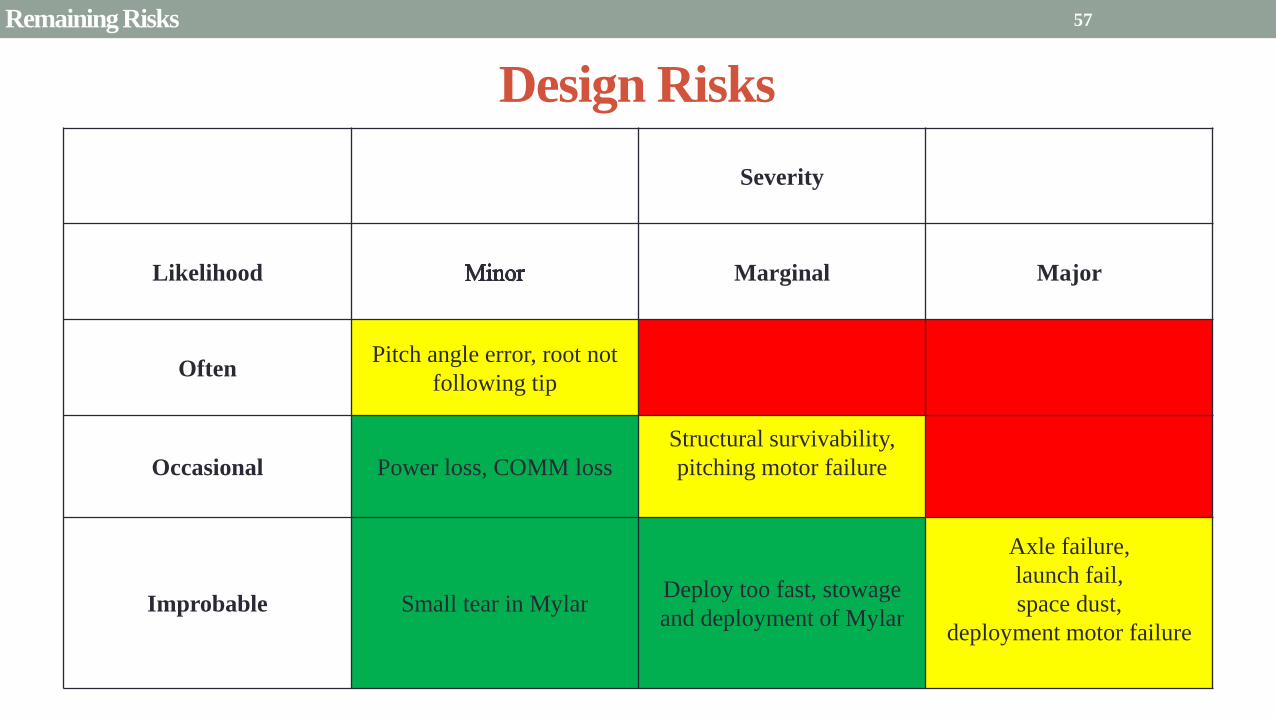
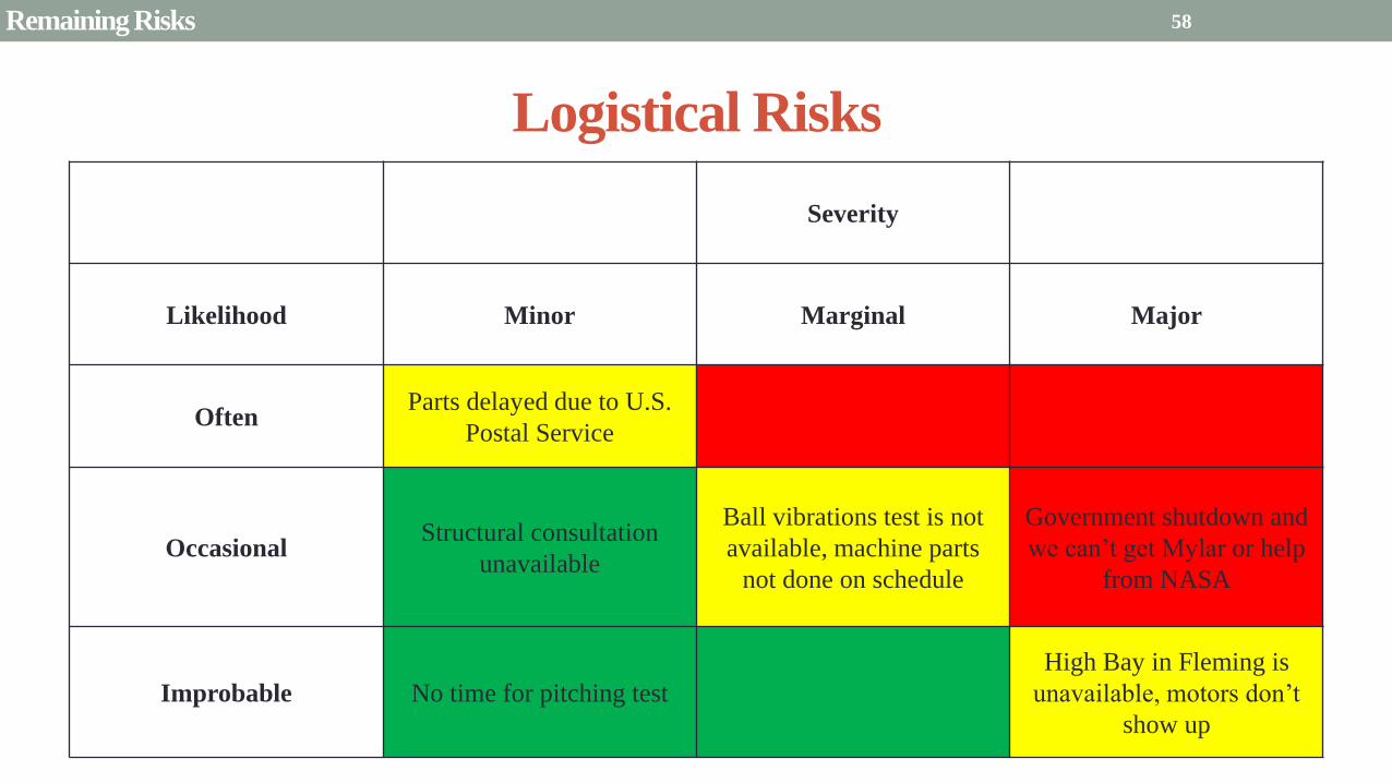
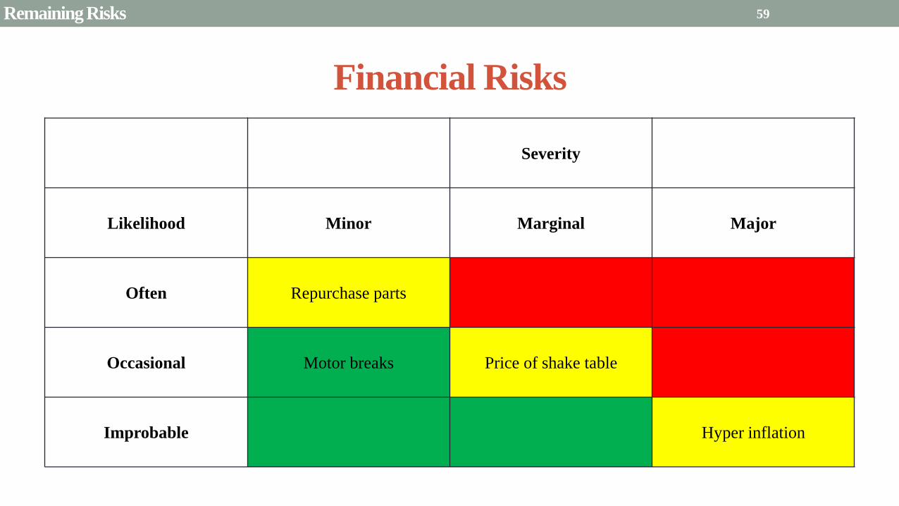
Presentation Sections
bullPurpose and Objectives
bullGHOST Design Solution
bullCritical Project Elements
bullRequirement Satisfaction
bullRemaining Risks
bullVerification and Validation of Design
bullProject Planning
60
Deployment System
Validate that the blade is deployed at a constant rate of 1-10 cms in a high bay
room
Verify that the motor can deploy at constant rate
Verify with test that the deployment system does not use more than the maximum power available of 10W
Validate that the blade can successfully deploy a blade with tape measure
material at a constant rate along ground
Verify with demonstration that the tape measure material can extend length of
blade
Verification and Validation
Verification and Validation
61
Blade Deployment Testing Information
bull Location Prof Frewrsquos High Bay Lab
bull Scheduled MarchApril with late night access to avoid
scheduling conflicts
bull Measurement Tape measure for distance and video
camera for time
bull Power Delivered 6253A Dual DC Power Supply
delivers 0-20 V and 0-3A
Tape measure
marking
distance up
wall
Kinematic Model
bull Torque from motor drives a constant velocity deployment
120591119898119900119905119900119903 = 120591119903119900119897119897 + 120591119901119906119904ℎ119894119899119892 119879119872 minus 120591119892119903119886119907119894119905119910 119879119872
120591119903119900119897119897 =119889119868119903119900119897119897
119889119905120596119903119900119897119897 + 119868119903119900119897119897
119889120596119903119900119897119897
119889119905
120591119901119906119904ℎ119894119899119892 119879119872 =119889119898119890119909119905
119889119905119903119903119900119897119897119907 + 119898119890119909119905
119889119903119903119900119897119897
119889119905119907
120591119892119903119886119907119894119905119910 119879119872 = 119898119890119909119905119903119903119900119897119897119892 bull 120649119945119952119949119941119946119951119944 = 120782 120782120790120787 N∙m 120649119950119952119941119942119949119950119938119961 = 120782 120782120782120789 N∙m
Power Supply
Verification and Validation
CubeSat Wire
62
Pitching System
Validate that the blade reel modules experience coordinated pitching
Verify that one blade reel module experiences periodic
motion
Verify that the blade reel module rotates to 0deg upon
initialization
Verify that the blade pitches to a given command
angle
Verify that the motorencoder system does not exceed power
available
Verification and Validation
Verification and Validation
63
Verify Pitching Angle Experiment Equipment and Specs
bull Use R60D RVIT (Rotary Variable Inductance Transducer) sensor to measure angles attaches to pin (red) in line with pitching axis bull Measures ranges of plusmn60deg rotation
bull Input Voltage = plusmn15 V
bull Output Voltage = plusmn75 V
bull Resolution = 0125 Vdeg
bull 119891119898119886119909 = 20 Hz
bull Use AD524 Precision Amplifier Instrumentation for signal conditioning bull Input Voltage plusmn10 V
bull Output Voltage plusmn10V
bull Requires Supply Voltage plusmn15
bull Use NI 9201 bull Input Voltage plusmn10 V
bull Has a USB output that can connect to a computer where vi program records
Experiment Set-Up
R60D RVIT
AD524
NI 9201 PC via USB
Verification and Validation 64
Verify Periodic Motion Experiment
bull Using the R60D RVIT set-up to measure deflection angles
bull With data of the angle deflection 120579 angular velocity 120596 and angular acceleration 120572 can be measured bull Motor restriction 120591119898119886119909 = 032 Nmiddotm
bull Model restriction 120596119898119886119909 = Ω2 if Ω = 2rpm 120596119898119886119909 = 02094 rads
Validation Model
bull R60D RVIT measures plusmn60deg deflection angles bull Critical condition blade reel module pitches plusmn90deg Ω=2rpm
bull 120572119888 = 00172 rads2 and 120596119898 = 0164 rads thus 120591119898 = 0083 mNmiddotm (119868119898119900119889 = 00048 kgmiddotm2)
120579 119905 120596 119905 120572 119905
Verification and Validation 65
Verification and Validation
Structural System
Validate that the final design can survive launch by using a shake
table
Verify the structural integrity by demonstrating that all stationary parts are
static
Verification and Validation 66
Trade Study FEM vs Vibration Table
Cost Time Experience
Similar to
Actual
Launch
Guaranteed Can
Do Total
FEM 4 1 1 3 4 215
Vibration
Table 2 3 4 4 2 32
Weight () 5 30 25 20 20 100
67 Verification and Validation
See Appendix for Full Trade Study
Validate Structural Stability
bull Will use a shaker table from Ball Aerospace
bull Cost = $250hr
bull Schedule Time to be determined in April
bull Specifications Peak vibration occurs with 34g at
frequency of 16 Hz (Saturn V)
bull Will be verified by examining the structural integrity
of the manufacturing
Verification and Validation 68
CubeSat
Shake Table
Presentation Sections
bullPurpose and Objectives
bullGHOST Design Solution
bullCritical Project Elements
bullRequirement Satisfaction
bullRemaining Risks
bullVerification and Validation of Design
bullProject Planning
69
Organizational Chart
Mark
Dolezal
Emily
Proano
Lauren
Persons
Casey
Myers
Nicholas
Busbey
Taylor
Smith
Karynna
Tuan
Megan
Scheele
Project
Manager
Software
Lead
Electrical
Lead
Systems Test and
Safety
Manufacturing
Lead Mechanics
Lead
CFO and
Materials
Lead
Organizing
team
meetings
Supporting
other leads
Non CPE
Tasks
Deployment
Control
Pitching
Control Motors and
Electronics
Power
Integrate
all system Perform
and Plan
tests
Manufacture
all in-house
parts
SolidWorks
Keep track
of financial
spending
Right
materials
are being
utilized
CubeSat
Assembly
Specific
System
Requirements
70 Project Planning
GHOST
Materials Mechanical Electrical Software Documents
Shake Table
Vibration
Analysis
Mechanical
Layout
Power Budget Pitch Control
Algorithm
Deployment
Rate Control
Algorithm SolidWorks
Model
Electrical
Wiring Layout
Thermodynamic
Analysis of
Electronic System
Mass Budget
Prototype of
CubeSat Bus
Motor
Subsystem
CDR
FFR
Spring
Schedule
Financial
Budget
Work Breakdown Structure (WBS)
Mylar from
NASA
Spin Up
Algorithm
Emergency
StopRestart System
71 Project Planning
PCB Design
Spring
Documents
113 120 127 203 210 217 224 303 310 317 324 331 407 414 421 428
MSR TRR SFR PFR
Time (date)
Purchase
motorsdrivers
Preliminary code
Electronic
integration
Test code
Electronicscode
interface
Purchase
raw materials
Manufacture frame
Assemble bus
Manufacture
remaining parts
Integrate system
Deployment test
Pitching test
Vibration test
Ta
sks
72
GHOST Spring Schedule
Project Planning
Planned Uncertainty
Key
Test Plan Test Scheduled Facility Specialized Equipment
Verify Pitch Angle 317 ITLL R60D RVIT NI 9201 AD524 Oscilloscope bench
power source
Zero Pitch Angle 317 ITLL R60D RVIT NI 9201 AD524 Oscilloscope bench
power source
Measure power used in
pitchdeployment 317 ITLL Ammeter voltmeter bench power source
Verify constant deployment 324 ITLL Firewire camera bench power source
ASEN2003BallTrackervi
Verify periodic motion 324 ITLL R60D RVIT NI 9201 AD524 Oscilloscope bench
power source
Validate tape measure ground
deployment 331 ITLL
Bench power source tape measure stop watch rollers
for tip mass
Validate coordinated pitching 331 ITLL R60D RVIT NI 9201 AD524 oscilloscope bench
power source
Validate 1g blade deployment 331-414 Prof Frew
high bay
Portable 6253A Dual DC Power Supply ladder tape
measure video camera
Validate launch ready 414 Ball Aero Shake Table
Project Planning 73
Cost Table ndash Structural Components
Part Price per
part NeededVolume Needed Total Price Supplier
Aluminum 6061 Sheet
(18rdquo thick) $ 8976 2ft times 2ft times 18 in $ 8976 The Metals Depot
Aluminum 6061 rod
(14 in diameter) $280 2 ft $280 The Metals Depot
Aluminum6061 rod
(716 in diameter) $494 2 ft $494 The Metals Depot
Steel Corner Brackets
(34rdquo times 12rdquo)
$197 4
braces 16 $788 Home Depot
Hardened 302 Stainless
Steel $3300 2 cm times 5 m times 127 microm $3300 McMaster-Carr
Total $11834
74 Project Planning
Cost Table ndash Electrical Components
Part Price per
part Needed Total Price Supplier
Sanyo Stepper Motor $ 5995 2 $11990 Pololu Electronics and Robotics
DRV8834 Low-Voltage Stepper
Motor Driver $995 2 $1990 Pololu Electronics and Robotics
FAULHABER 2036 BLDC
Servo Motor $23000 2 $46000 MicroMo Micro Motion Solutions
Atmel ATA6832-DK Brushless
DC Motor Controller $20800 2 $41600 Atmel
Encoder AU-ZSD1000A $22500 2 $45000 MicroMo Micro Motion Solutions
PIC18F87K22 Microcontroller $500 1 $500 Microchip
AD-524 Signal Converter $1767 1 $1767 Agilent
Total $148847
75 Project Planning
Questions
76
References
bull wwwloctiteproductscom
bull Vallado D A Fundamentals of Astrodynamics and Applications
bull Guerrant D Lawrence D Heaton A Earth Escape Capabilities of the Heliogyro Sail AIAA Paper
bull wwwspaceflightnowcom
bull Guerrant D HGVizGuim MATLAB Program
bull httpwwwmicromocombrushless-dc-motorsaspx
bull httpwwwfaulhabercomservletcomitmrwawservletAnzeigefremdaufruf=jaampkdid=40929ampsprachid=1amphtdigurl=n169933i95222html
bull httpwwwpololucom
bull httpasmmatwebcomsearchSpecificMaterialaspbassnum=MA6061t6
bull httpwwwruagcomthermalSpace_Thermal_HardwareMulti_Layer_Insulation
bull Helgesen Bryan Sierra Nevada Corporation
77
GyroSail Launch Configuration and Deployment Sequence
78
1 Launch configuration (6U) 2 Blade reel modules pitch to zero Fits within a 6U or 12U dispenser
3 PV arrays deploy
Other array configurations are possible
williamkwilkienasagov NASA PREDECISIONAL - FOR DISCUSSION PURPOSES ONLY
78 Appendix
GyroSail Primary Bus Systems Based on modified JPLU MichUCLACal PolyUT INSPIRE bus
williamkwilkienasagov
05U cold gas thruster ACS for detumbling
and initial spin-up
(httpwwwaustinsatnet)
05U EPS battery CampDH UHF backup
comms (U Mich) 05U DSN-compatible X-band
communications (JPL)
05U COTS star trackerimager ADC (BCT) sail
module processor (CU)
Klesh A et al 2013 ldquoINSPIRE Interplanetary NanoSpacecraft Pathfinder In Relevant Environmentrdquo Proceedings of the AIAAUSU Conference on Small Satellites Around the Corner SSC13-
XI-8 httpdigitalcommonsusuedusmallsat2013all2013127
NASA PREDECISIONAL - FOR DISCUSSION PURPOSES ONLY
79 Appendix
COMM Subsystem
bull 18 m Ka-band antennas at White
Sands New Mexico
bull Goddard Space Flight Center
Greebelt Maryland USA
supplied the Mulemba Space
Center in Angola
80 Appendix
Orion Crew
Module
6U Canisterized Satellite
Dispenser (CSD) ESPA Ring
Spacecraft
Adapter
Interim Cryogenic Propulsion
Stage (ICPS)
Secondary Payload Attachment to SLS
The SLS design is currently going through CDR An ESPA
ring is not currently in place but is mentioned in the SLS
CONOPS in order to accommodate secondary payloads
81 Appendix
Max Thrust Condition Collective 90deg pitch profile
Max thrust normal to orbital plane
(Halo orbits orbital plane rotation ie
inclination change)
82
Credit to Dan Guerrant
Appendix
Max Thrust Condition
F vs β M vs β
83
Credit to Dan Guerrant
Appendix
No Thrust Condition Collective 0deg pitch profile
Zero thrust
84
Credit to Dan Guerrant
Appendix
No Thrust Condition
F vs β M vs β
85
Credit to Dan Guerrant
Appendix
Max Torque Condition Collective 35deg pitch profile
Max torque used for spinning up sc
(opposite orientation for despinning)
86
Credit to Dan Guerrant
Appendix
Max Torque Condition
F vs β M vs β
87
Credit to Dan Guerrant
Appendix
Max In-Plane Thrust Condition Cyclic 35deg pitch profile
Max thrust in in-plane (d2) direction for orbit raising
88
Credit to Dan Guerrant
Appendix
Max In-Plane Thrust Condition
F vs β M vs β
89
Credit to Dan Guerrant
Appendix
Orbit Raising
F
90 Appendix
Thermal Space Concerns
bull Material Concerns
bull Aluminum 6061 -196 degC to 160deg C
bull Electronics Concerns
bull Typical Operating Temperature -55 to 80 degC
bull Countermeasures
bull Multi-layer Insulation AAErotherm S10-190
bull (0005 ndash 0035 Wm2K)
bull Battery operated heaters for pre-sail deployment
Multi-layer Insulation
Layer 1 1 x Outer layer
Layer 2 8 x 03 mil VDAPolyimideVDA perf
8 x Woven Polyester netting
Layer 3 1 x Outer layer
Layer 4 1 x Woven Polyester netting
91 Appendix
Rolled Up Blade Reel Calculation Optimal Sail Length 545 m ndash Sail chord of 14 cm
Max Diameter of Spool 598 cm
Diameter of Axle 05 cm
Length of Stiff Material 5 m
Dimension of Stiff Material 5 m times 2 cm times 127 microm
92 Appendix
Torque calculation
bull Note current calculated via T=kI (where T is torque I is amp k is the torque
constant specific to the motor)
T = kI
(k = 005 NmA)
93 Appendix
Servo Controller
94 Appendix
Encoder Dimensions and Interface
bull FAULHABER IE2-1024
95 Appendix
Stepper Motor Torque
96 Appendix
Motor Phases (Stepper)
97 Appendix
98 Appendix
99 Appendix
100 Appendix
101 Appendix
Microcontroller
102 Appendix
ATA6832 Phase Output Chip
103 Appendix
ATA6624 Bypassed Chip
bull Bypassed chip
on servo controller
104 Appendix
Power Budget
105 Appendix
Wire Gauge
bull Stepper Motor 26AWG (04 mm diameter)
bull Servomotor 24 AWG (051 mm diameter)
bull Encoder 24 AWG
Voltage Drop () AWG Max Gauge
001 5
01 15
1 25
5 32
NOTE Voltage drop calculated at 1A and 40 cm of wire
106
24 AWG Wire
Appendix
Trade Study ndash FEM vs Vibration Table
Factor 4 3 2 1
Cost No money 0 gt C gt $100 $100 gt C gt $300 $300 lt C
Time 0 min lt T lt 30 min 30 min lt T lt 2 hrs 2 hrs lt T lt 1 day 1day lt T
Experience Everyone has
experience
A couple people
know how to
1 person has
experience
No one has
experience
Similar To Actual
Launch Simulate real launch
Doesnrsquot have all
variables experienced
Has only a couple
similarities
No similarities to
launch
Guaranteed Can Do
Donrsquot need any
outside equipment or
help
Need outside
equipment but
guaranteed use
Need outside
equipment but own
work at higher
priority
Need outside
equipment but canrsquot
use
Scoring
107 Appendix
Weighting
Weight () Category Reasoning
5 Cost Have a lot of extra $ in the budget
30 Time Have a strict schedule but not a main focus of the
project
25 Experience If no one has experience it will take a lot of time
20 Similar to Actual Launch Needs to be like actual launch
20 Guaranteed Can Do Needs to be able to accomplish but not the most
important focus
108 Appendix
Finite Element Method (FEM)
Objectives Description ProCon
Cost No money because one of us
would do it Pro
Time A lot of time to learn and then
perform FEM Con
Experience No one in group has FEM
experience Con
Similar to Actual Launch Very similar to actual launch Pro
Guaranteed Can Do All we need is paper pen and
theory to do Pro
109 Appendix
Vibration Table
Objective Description ProCons
Cost $250hr Con
Time A hour on the table should simulate
launch Pro
Experience Donrsquot need experience to run
vibration table Pro
Similar to Actual Launch Actually putting our system through
vibration stress Pro
Guaranteed Can Do No guarantee but most likely can Con
110 Appendix
SpinUp State
1 Check value of SpinUp to see if satellite is already spun up
bull Continue if satellite is not already spun-up
2 Deploy the tape stiffened length of the blade
3 Pitch to the spin up angle
4 Wait until characteristic angular velocity is reached
5 Pitch to pre-deployment position
6 Save SpinUp as completed
Appendix 111
Deployment State
1 Check if satellite has been spun up yet
bull Continue if it has
2 Check if blades are already deployed
bull Continue if they havenrsquot
3 Run deploy algorithm until blades are fully deployed
4 Save value saying blades have been deployed
Appendix 112
Pitching State
1 Check if satellite has been spun up
bull Continue if satellite has been spun up
2 Check if blades have been deployed
bull Continue if blades have been deployed
3 Look at commanded pitch profile
4 Find correlated sinusoid command
5 Command servo to pitch angle for the time in the orbit
6 Continue until given a new pitch command
Appendix 113
Emergency Stop
1 Save which state was interrupted
2 Save last position in interrupted
state
3 Wait until Restart command is
received
1 Check two previous states to see
what is being restarted
2 Look at saved last position in
state being restarted
3 Adapt the algorithm of the state
to continue where left off
Restart
Appendix 114
Comparison with Previous Heliogyro Concepts MIT (1989) NASA (2011) GHOST
Total sail craft mass (kg) 18 84
288 (6)
Characteristic acceleration ac
(mms2) 06 10 03868 (01854)
Sail reflective area (m2) 1200 960 1526
Non-sail mass (kg) 5 5 --
Number of sail blades 8 6 2
Blade chord (m) 15 08 014
Blade length (m) 100 200 545
Rotational period (minutes) 3 3 1
Blade root stress (Pa) 8650 34000 --
Blade root allowable stress (Pa) 55 M 55 M --
Blade root tension load (N) 01 007 --
115 Appendix
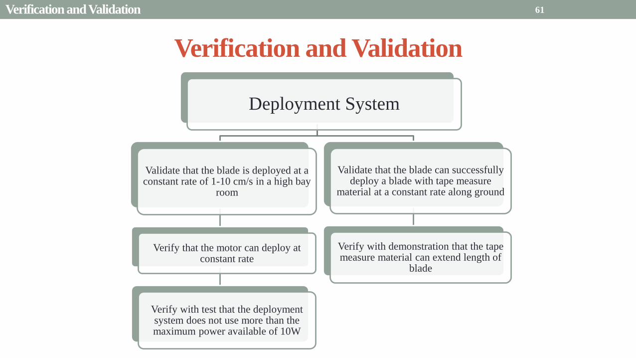
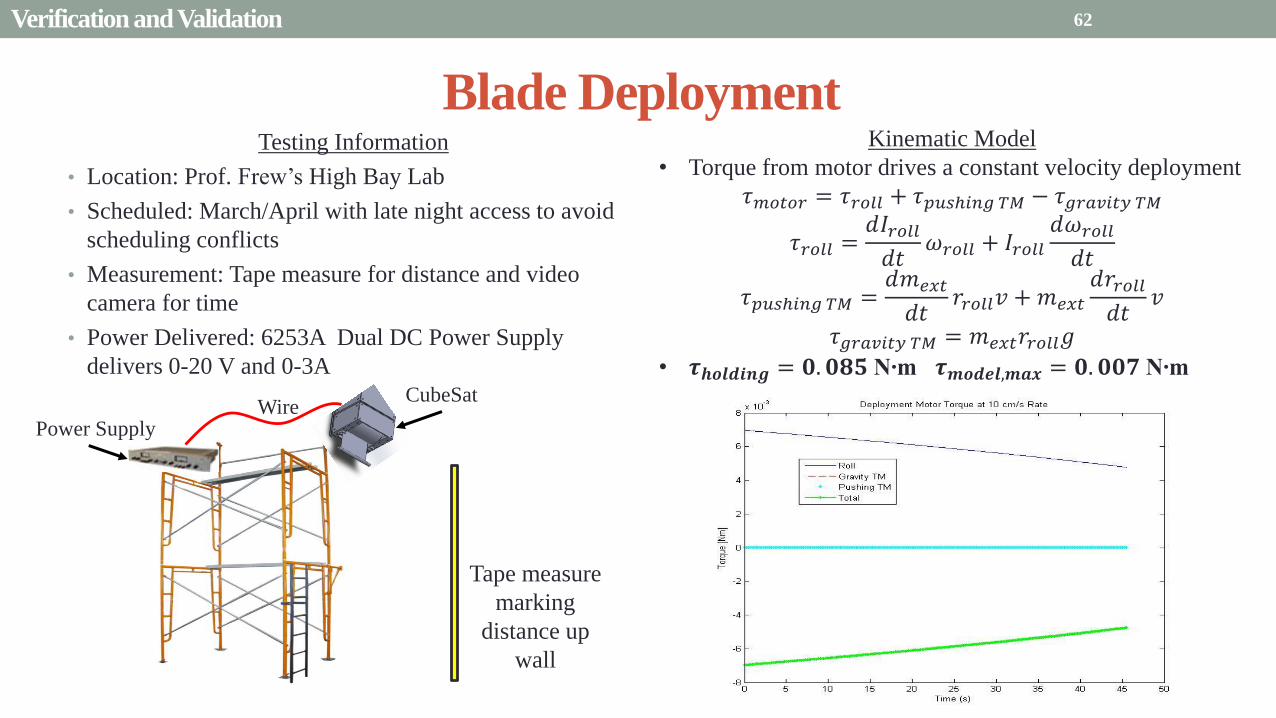
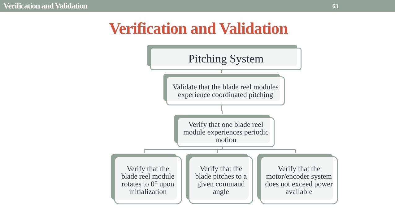
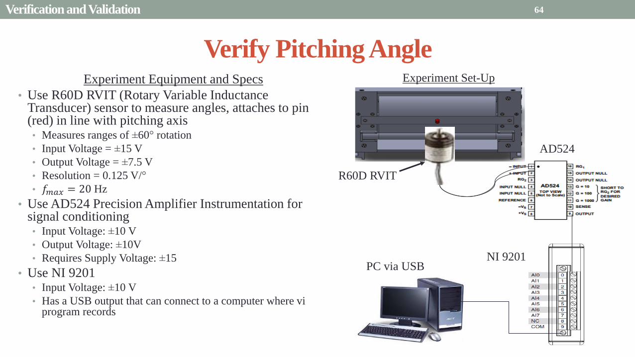
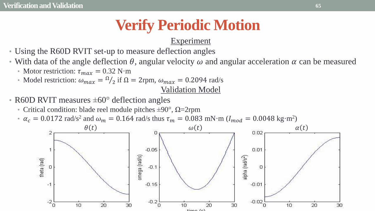
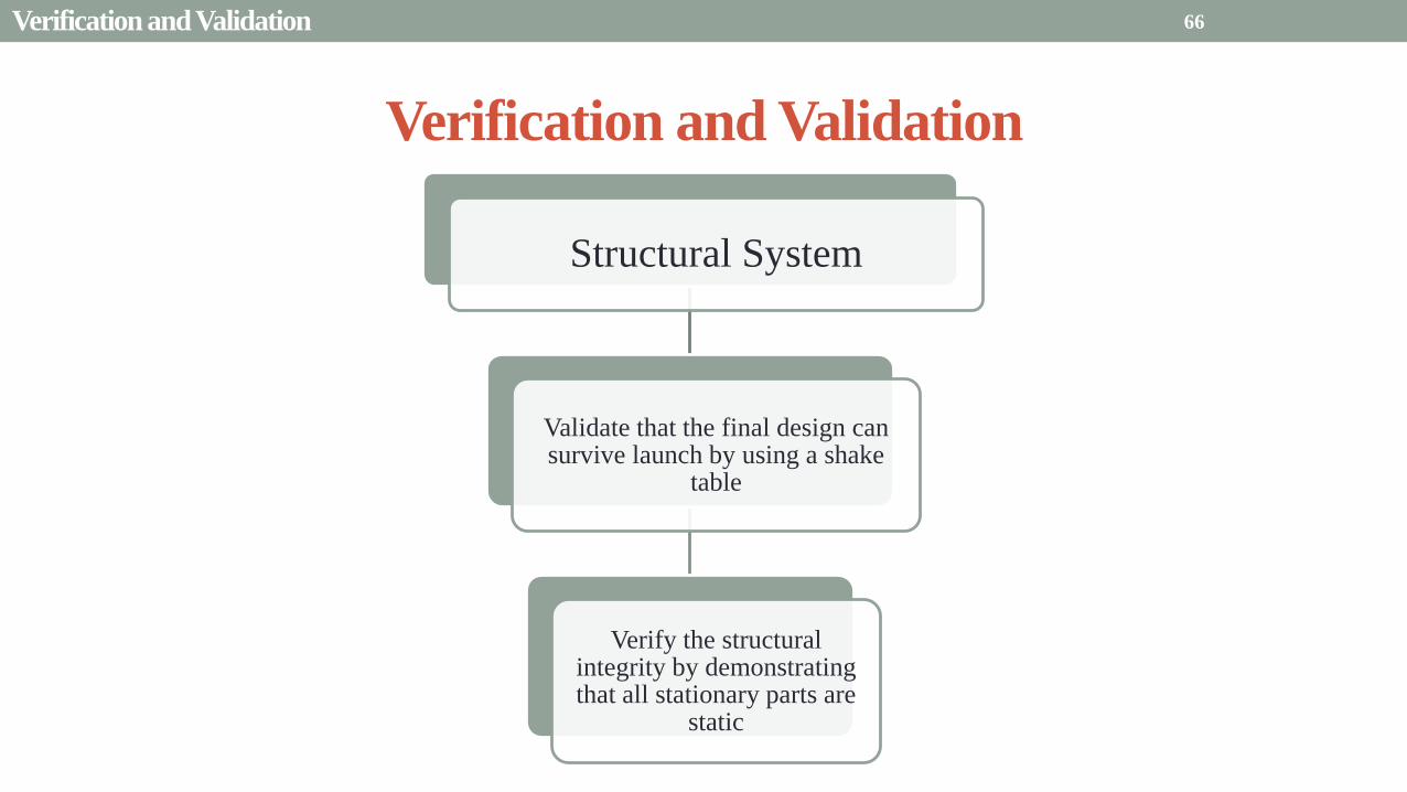
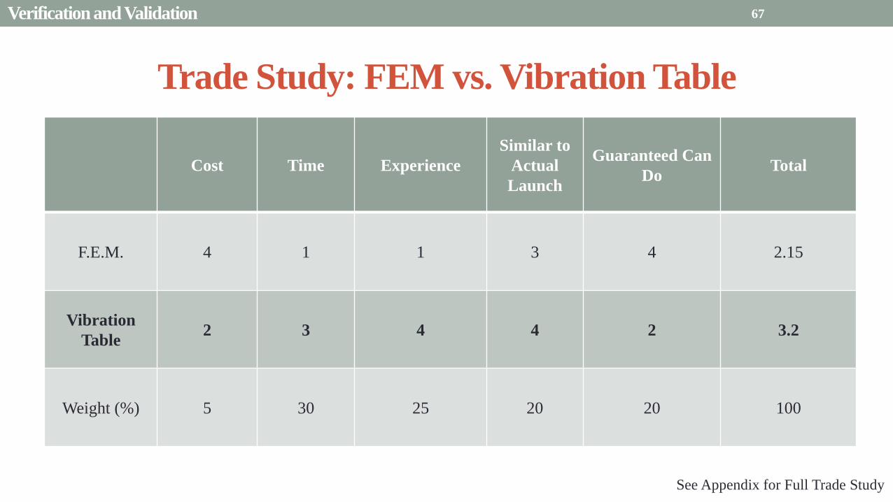
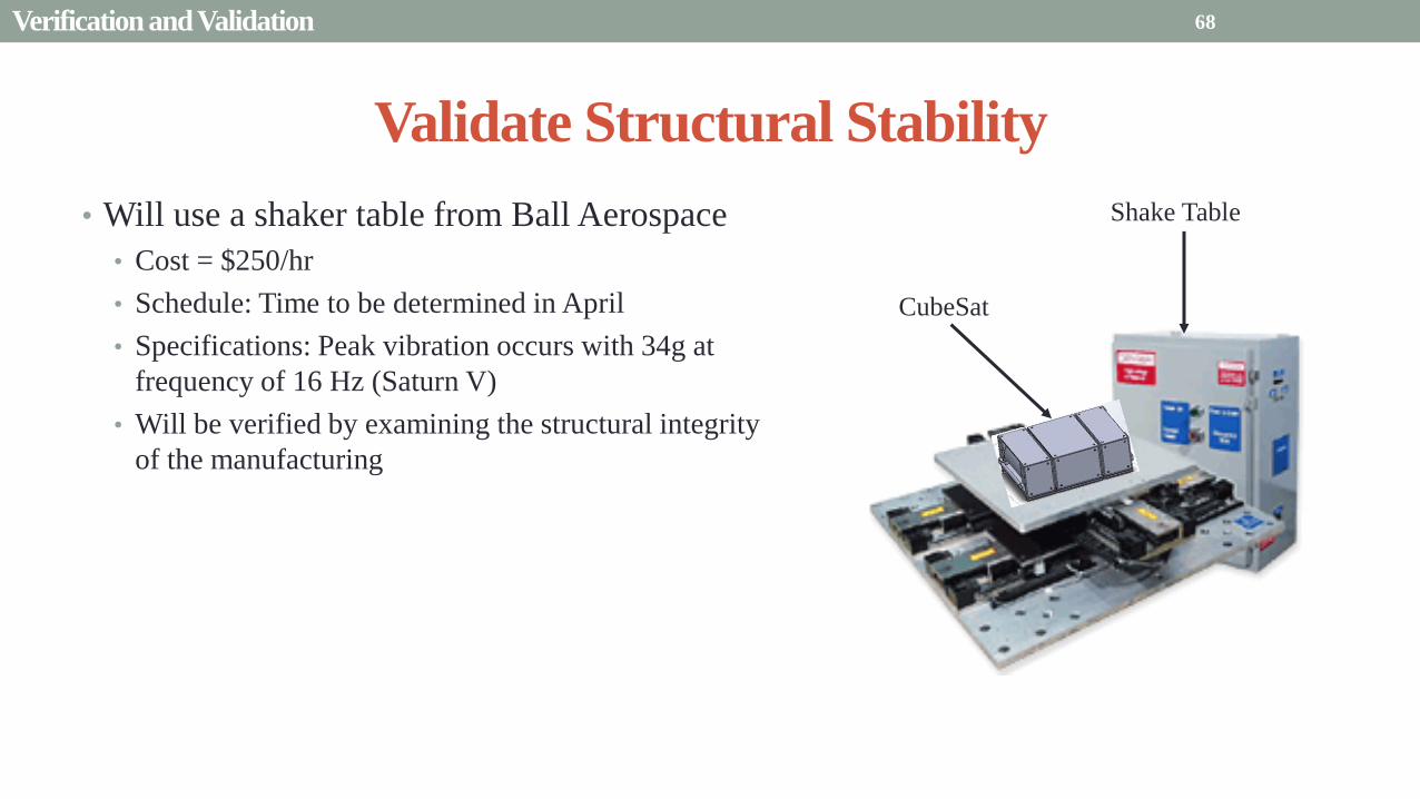
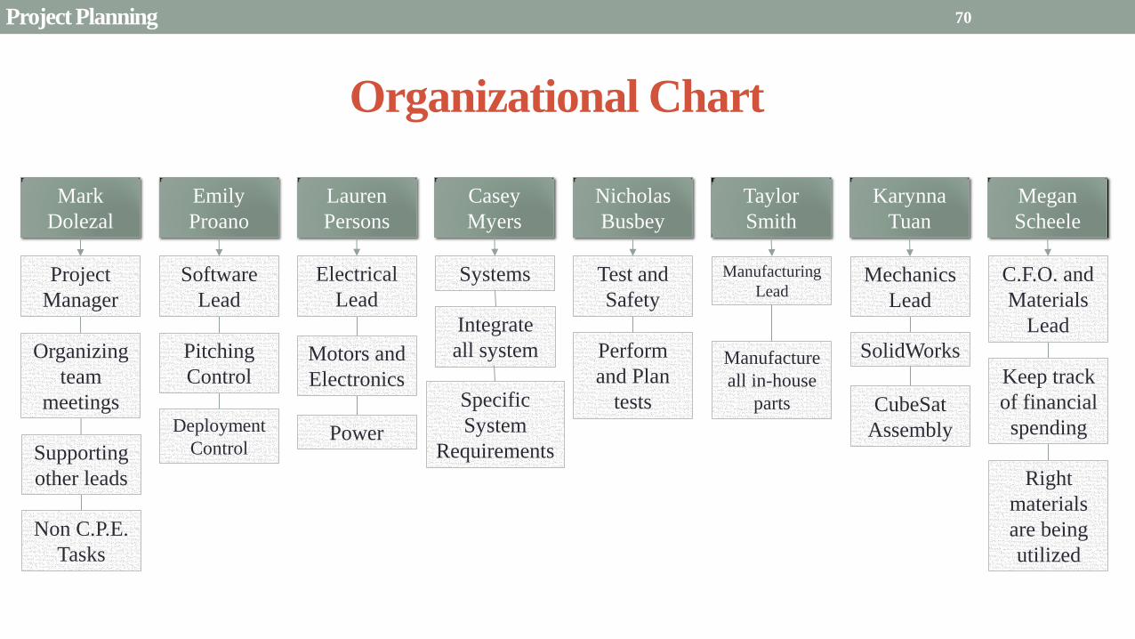
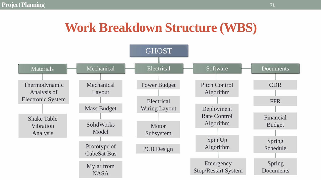
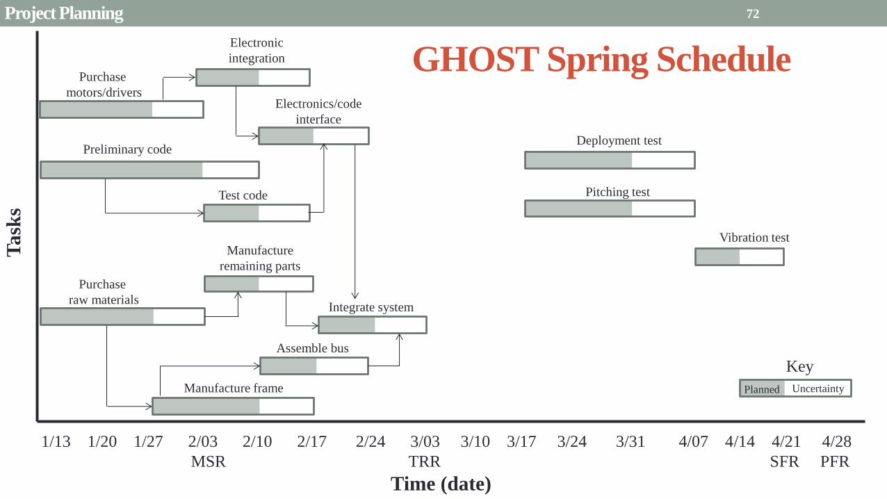
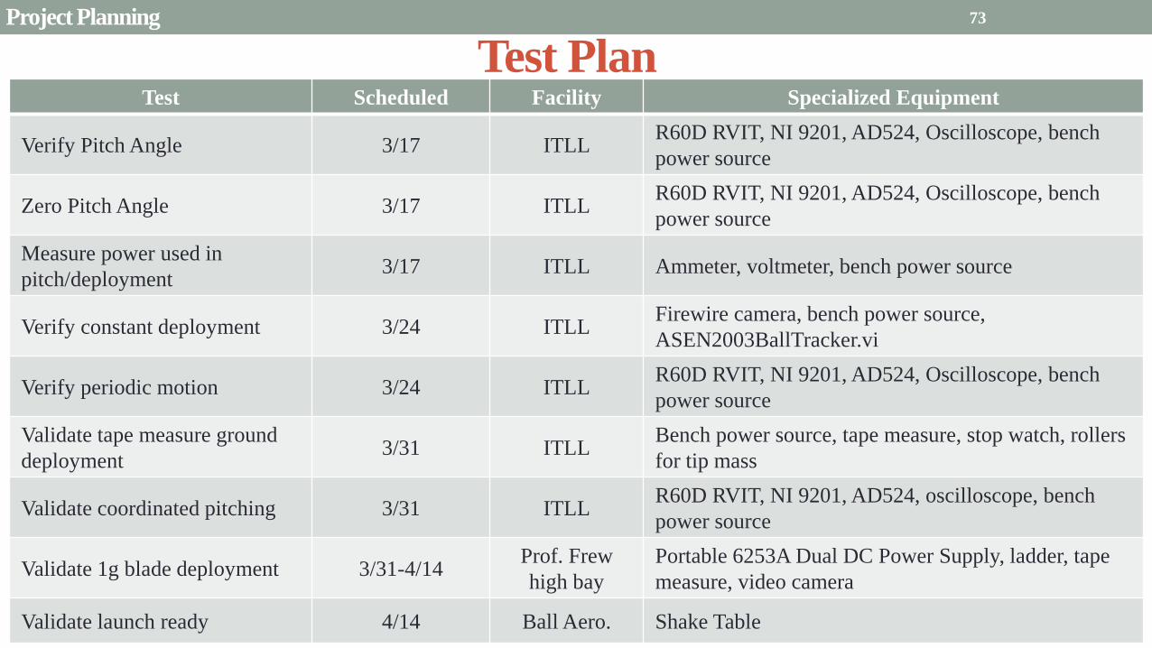
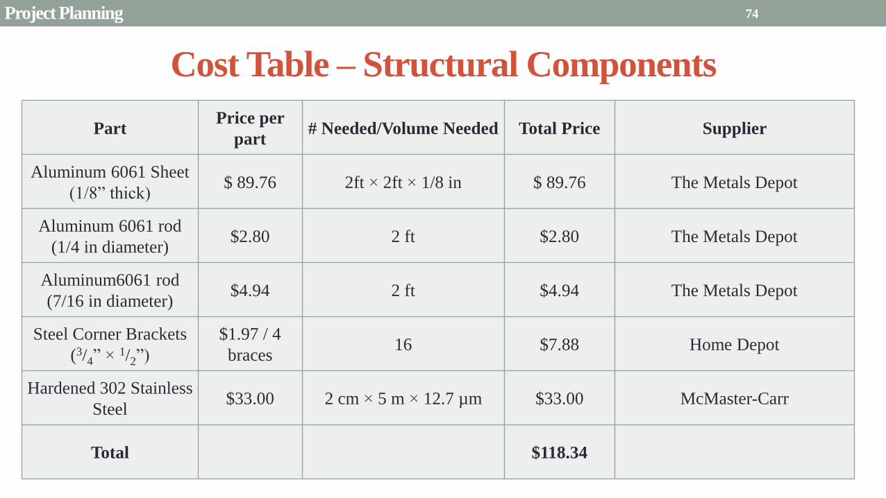
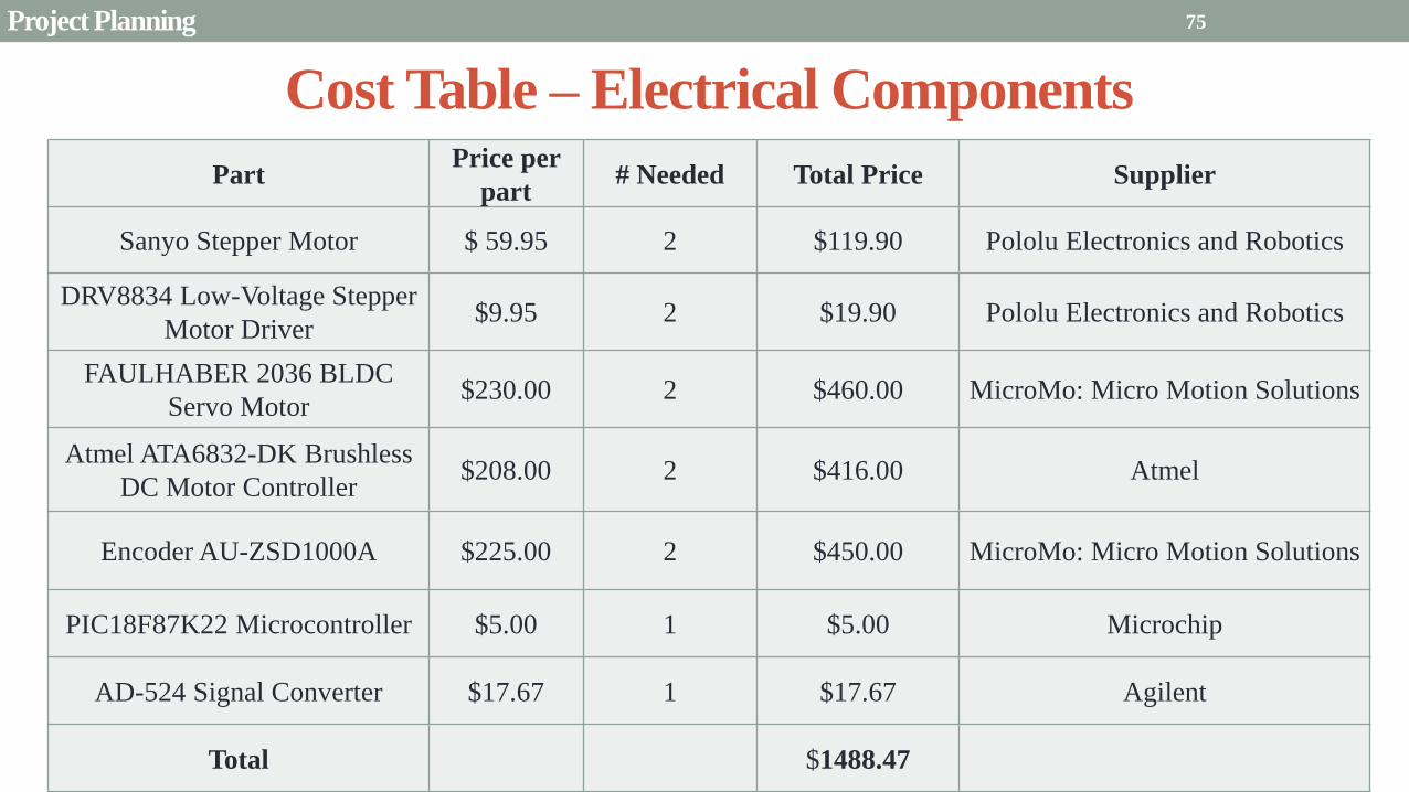
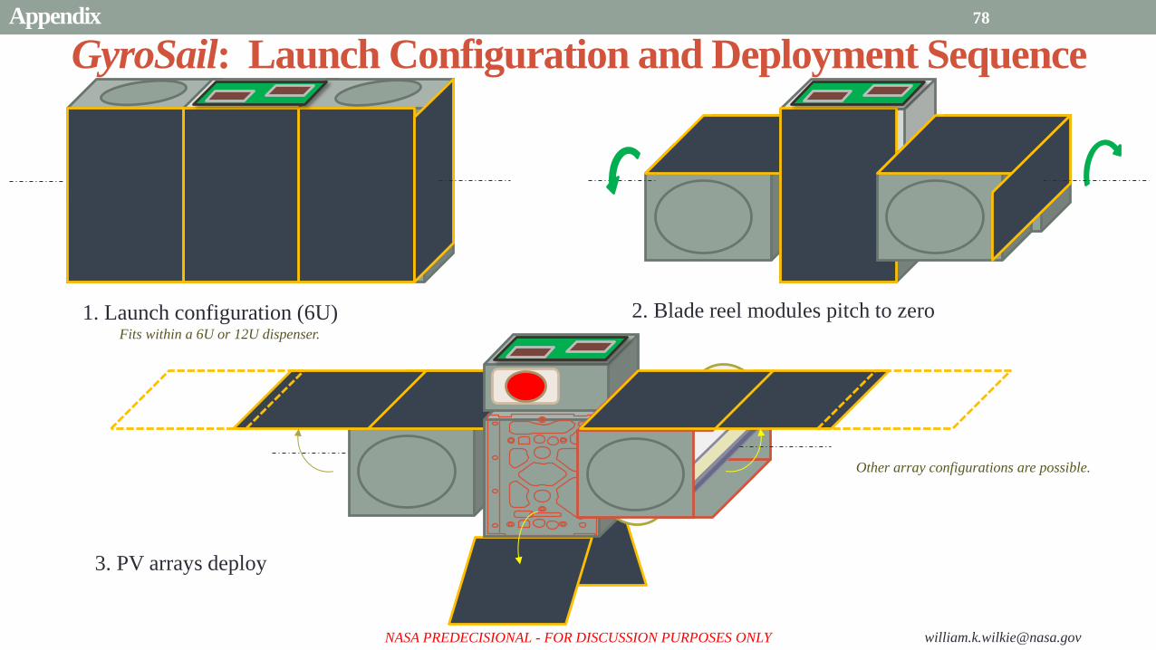
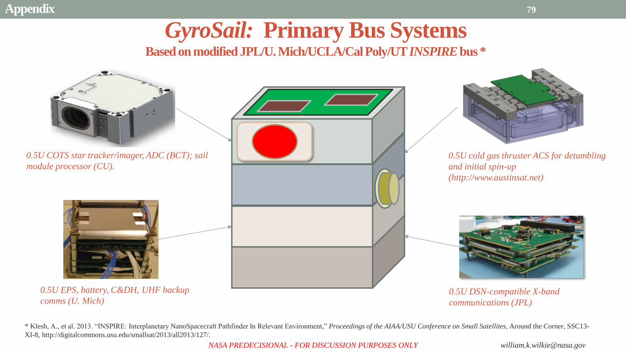
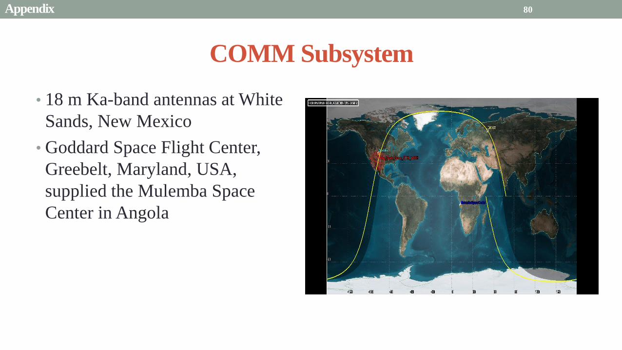
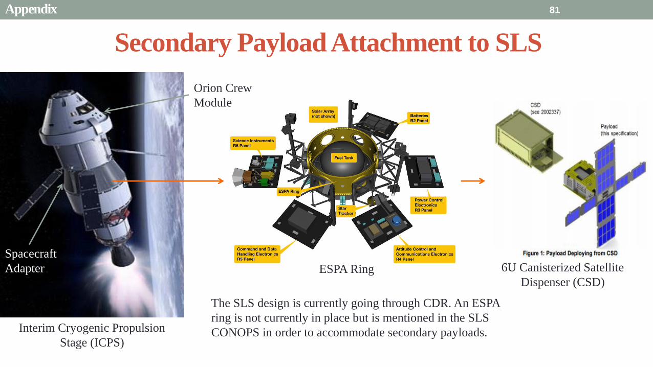
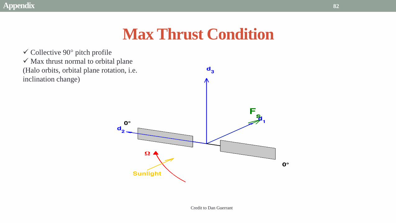
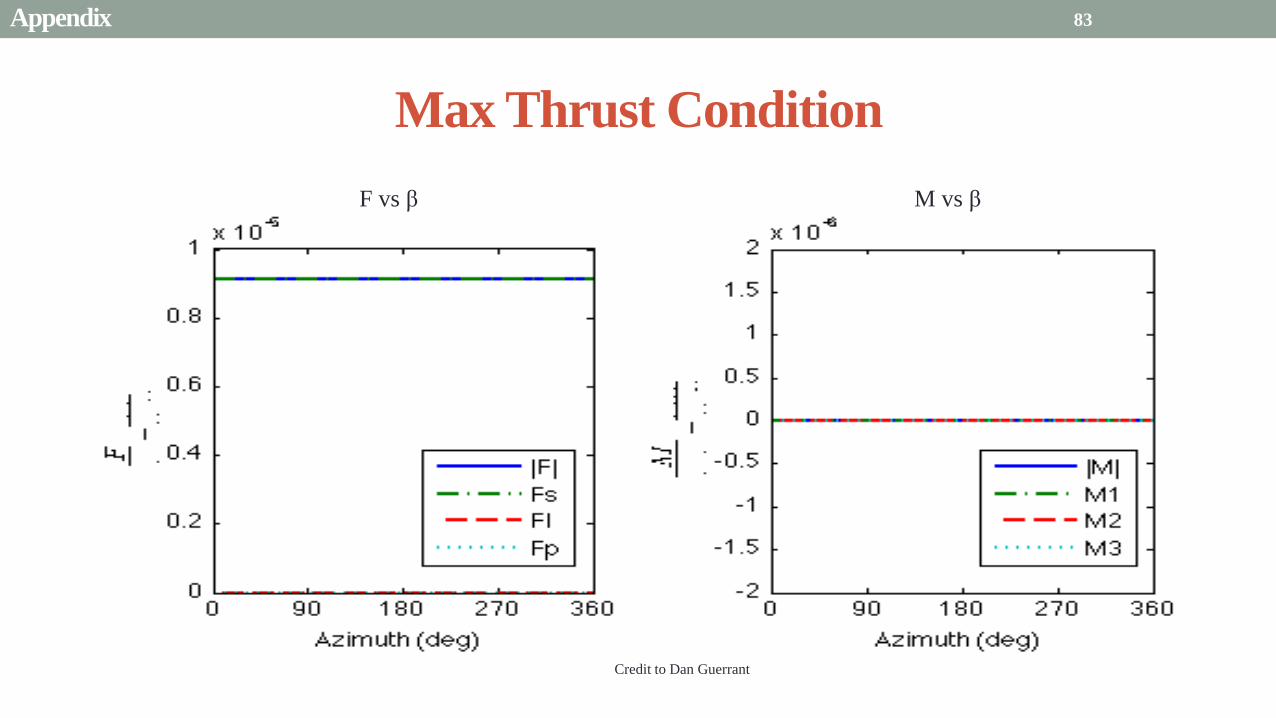
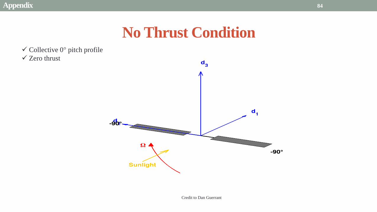
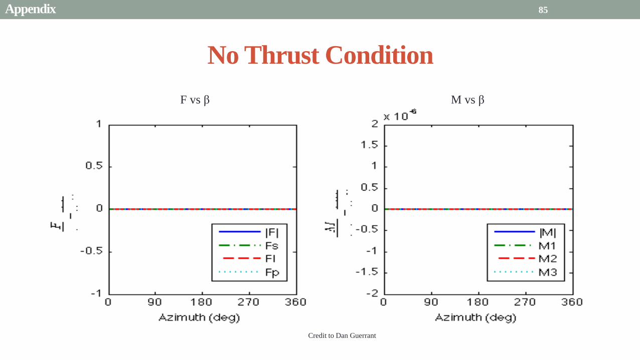
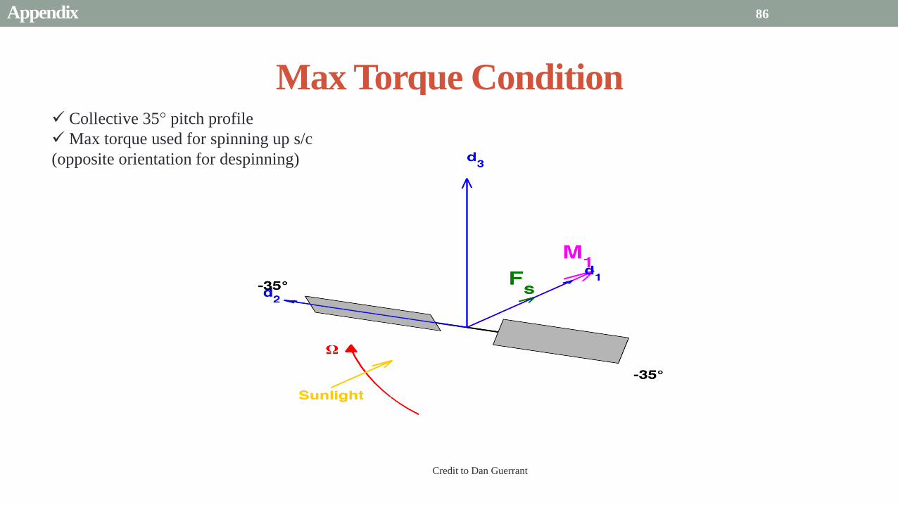
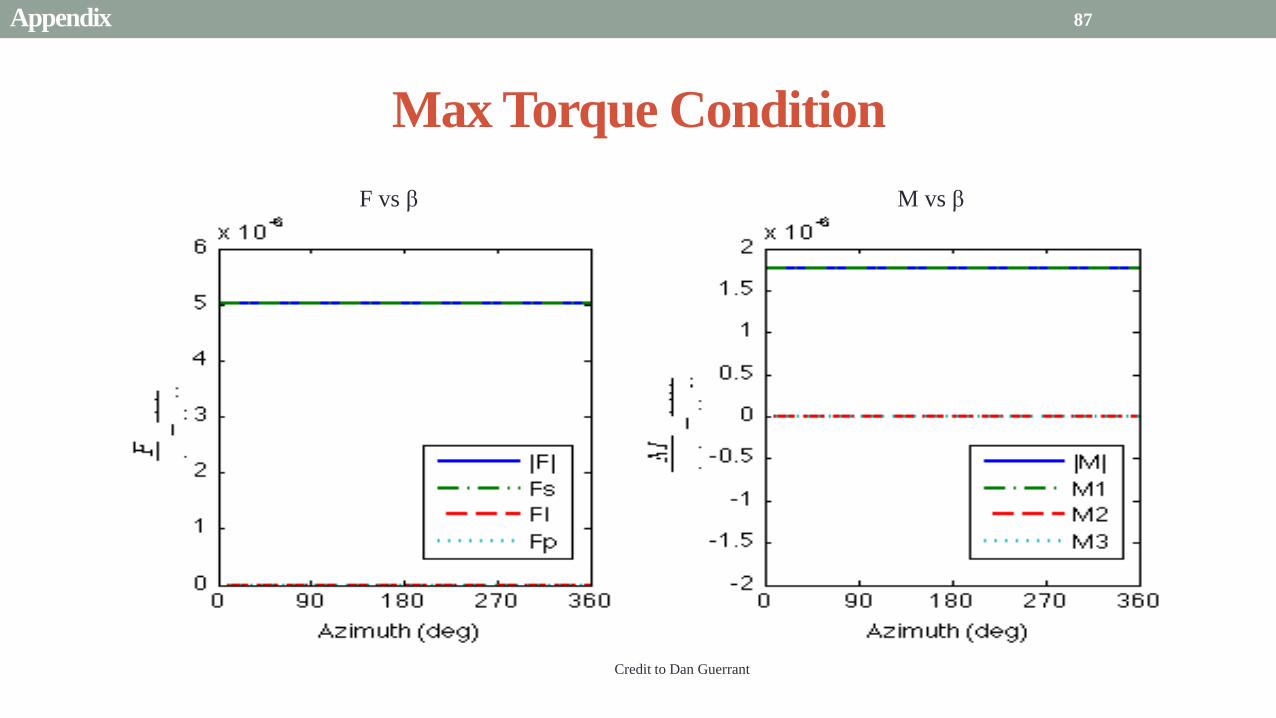
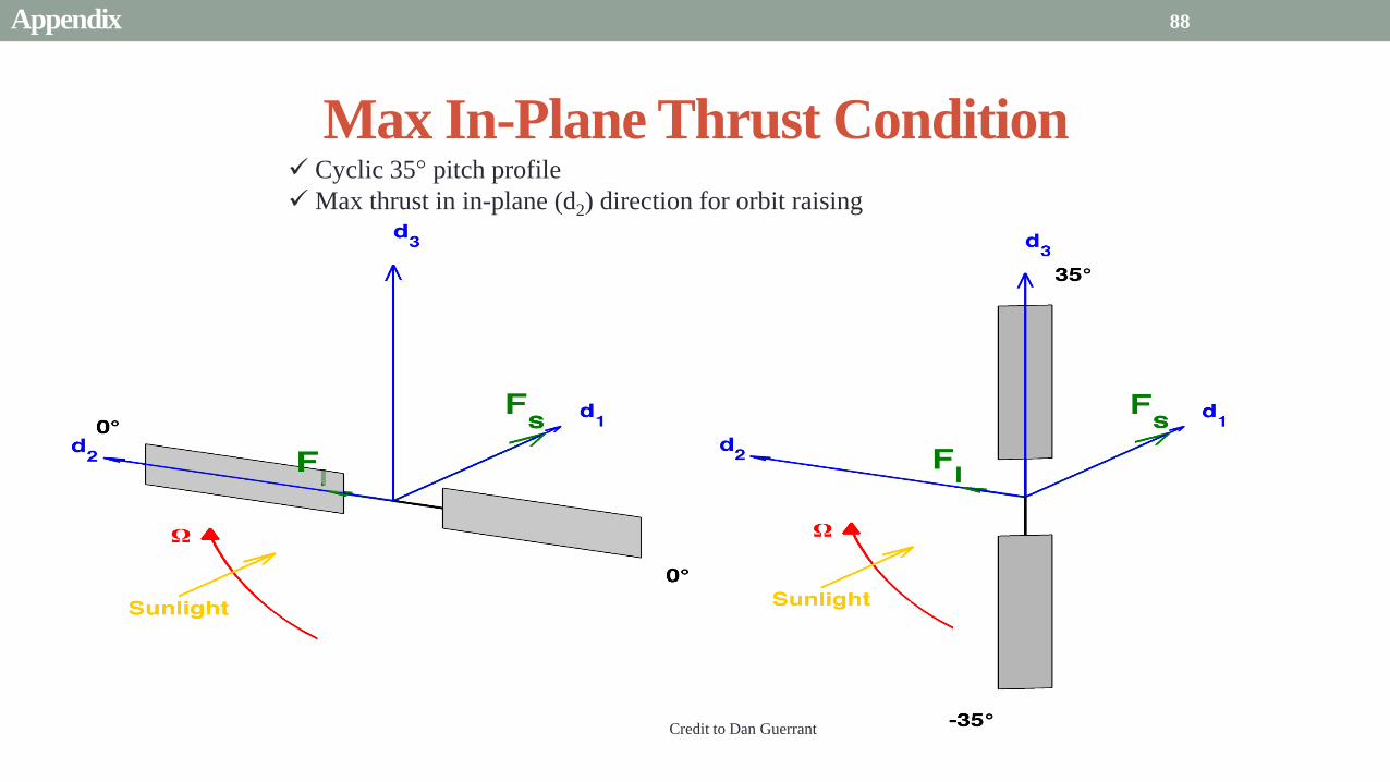
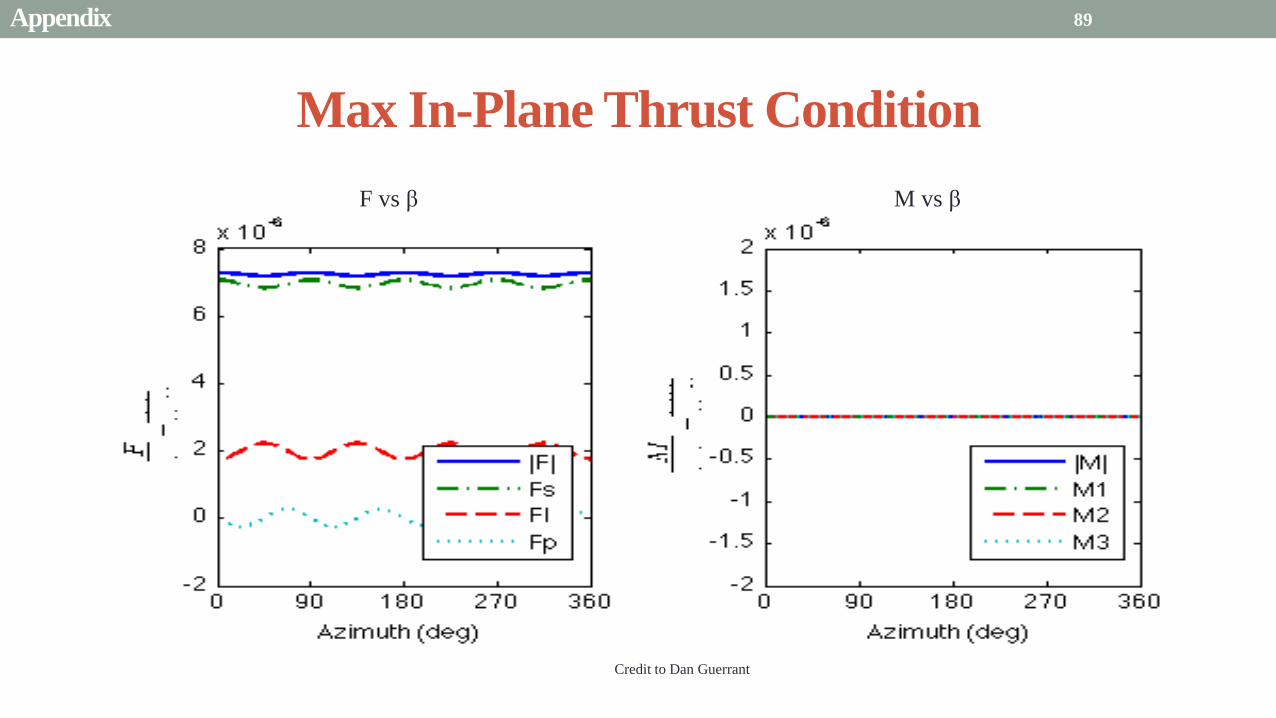
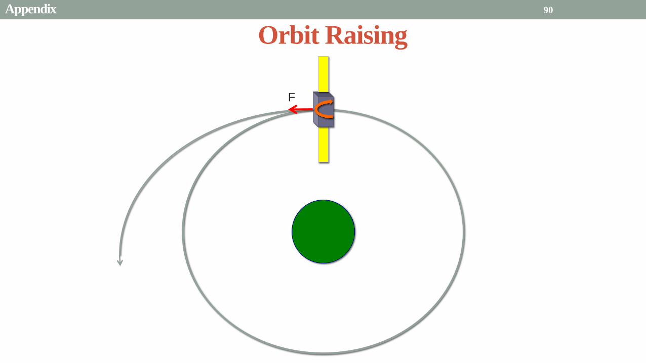
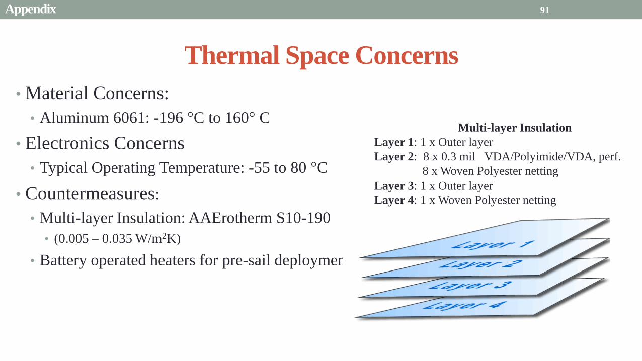
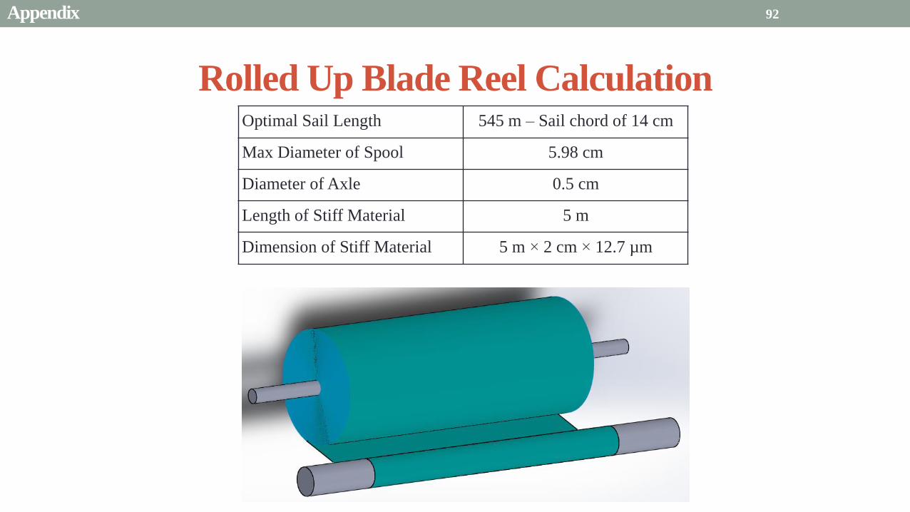
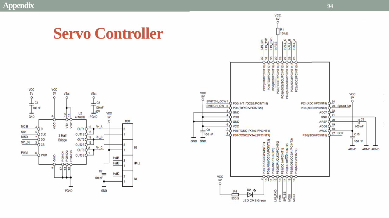
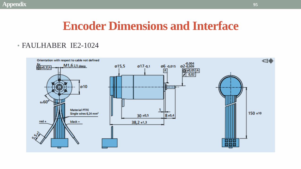
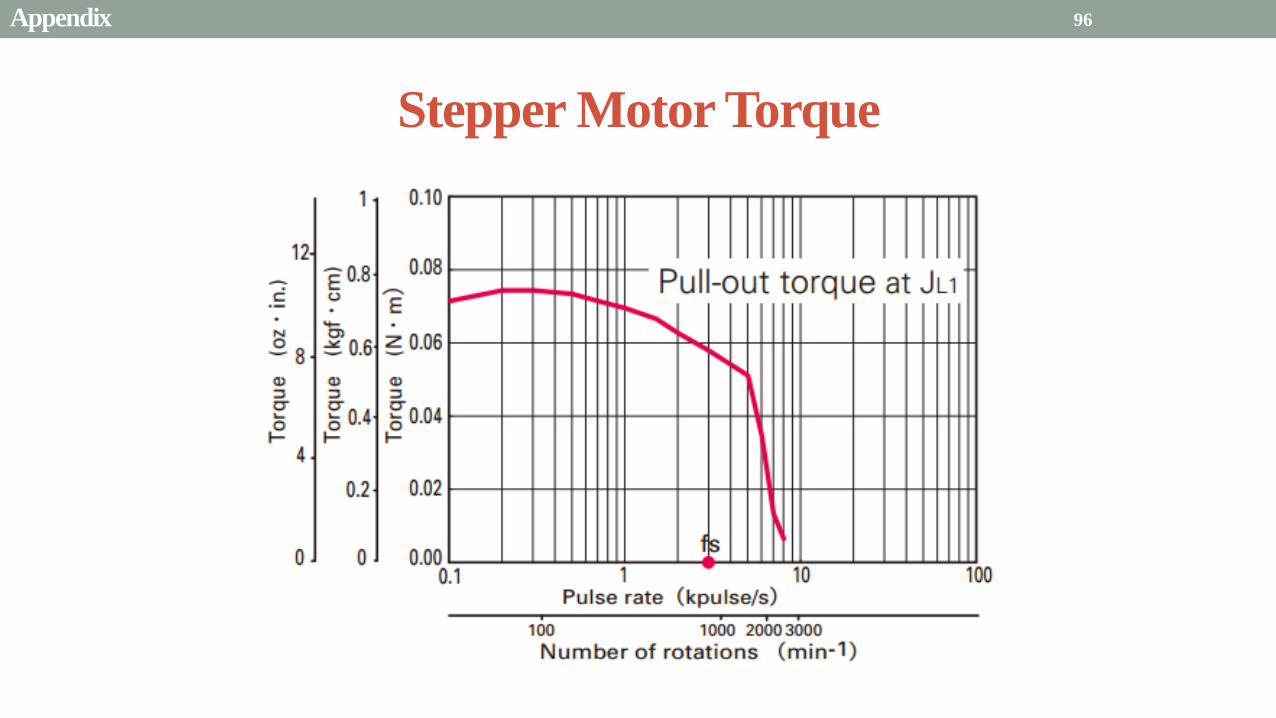
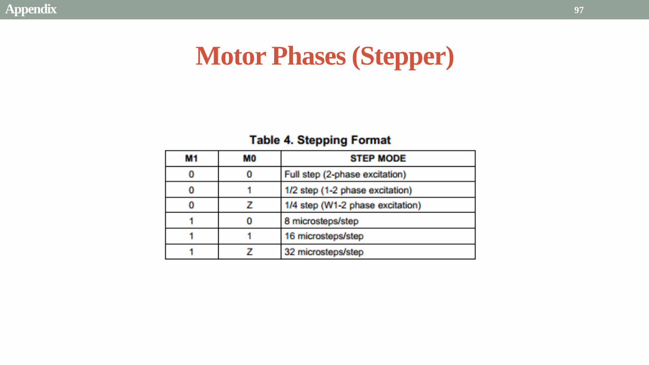
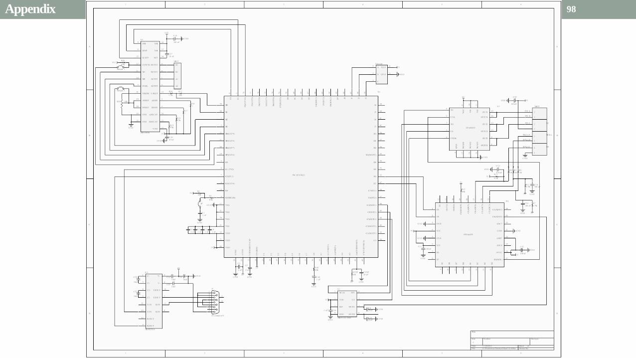
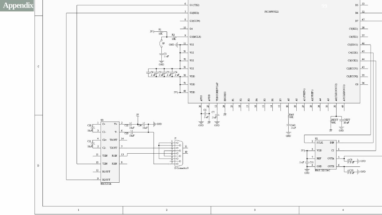
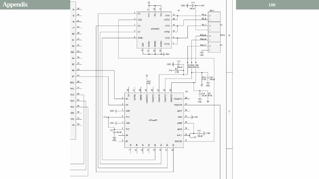
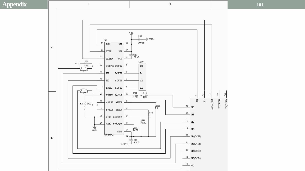
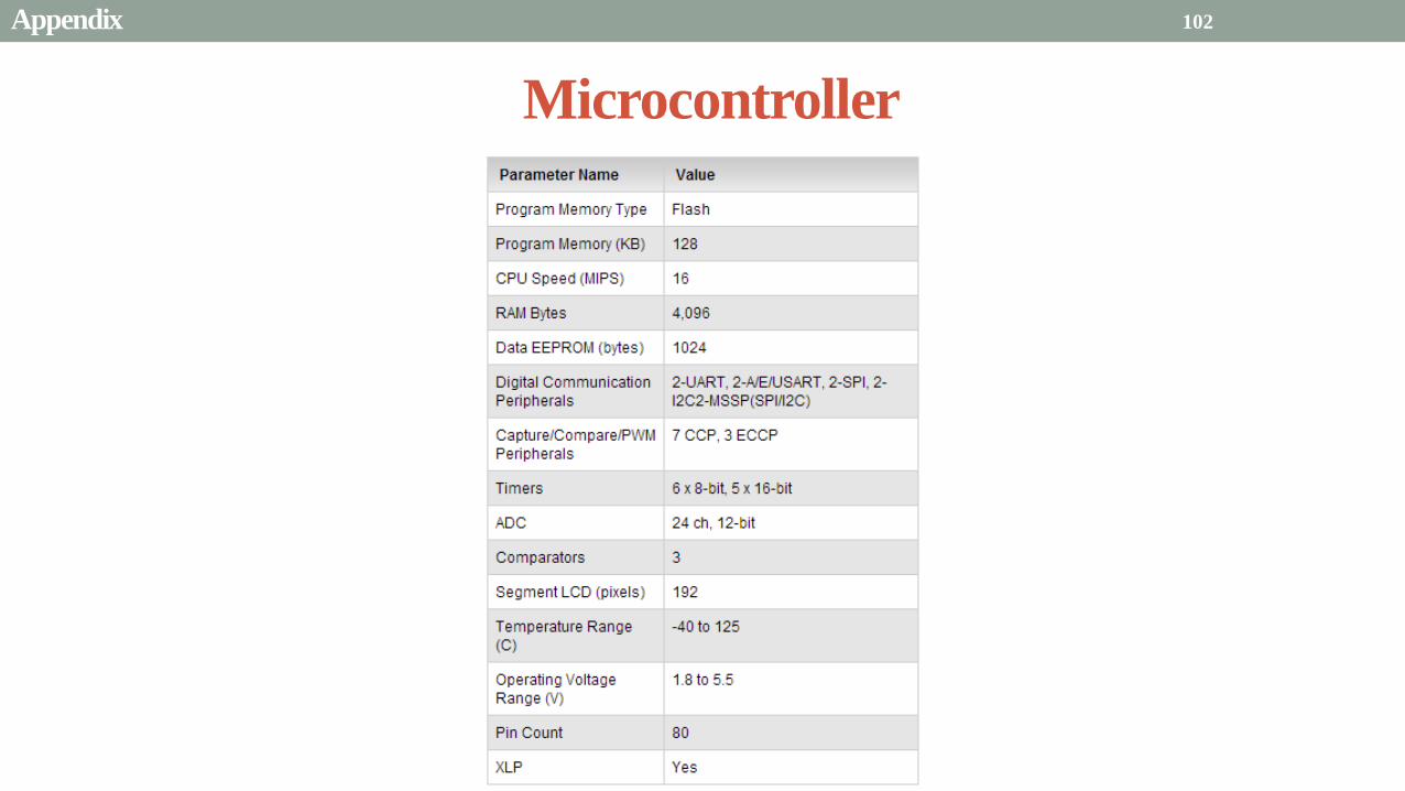
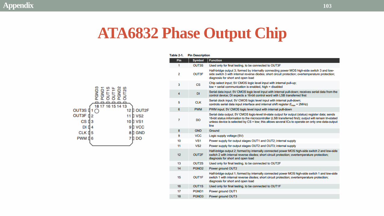
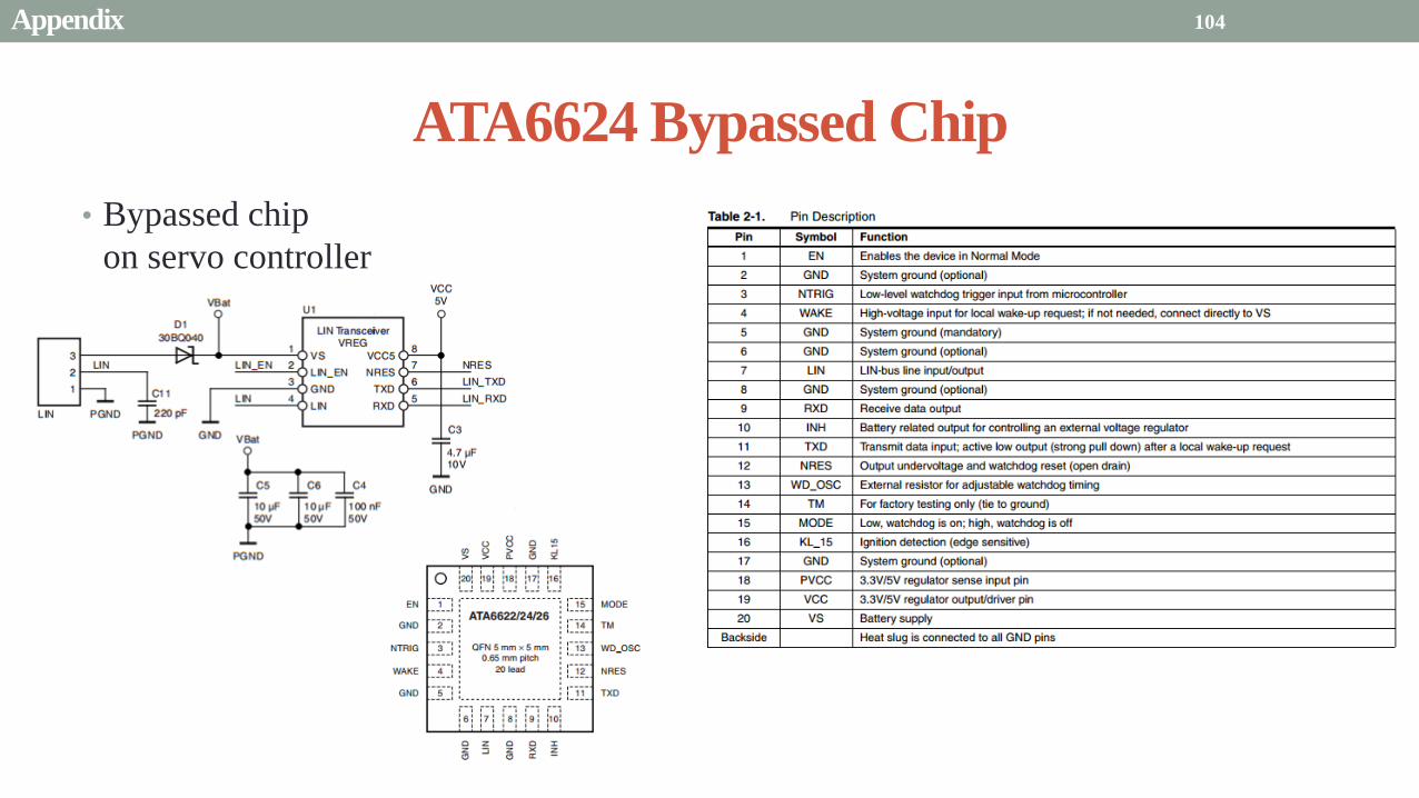
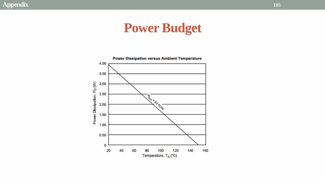
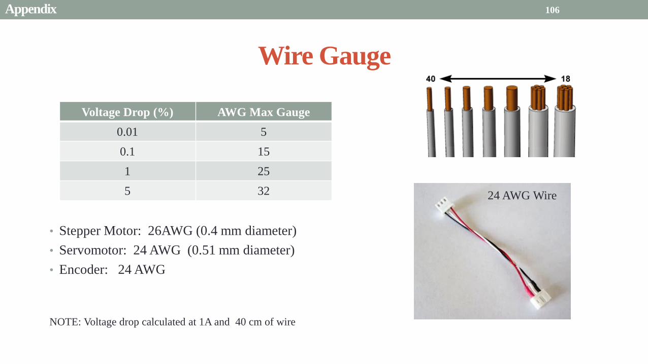
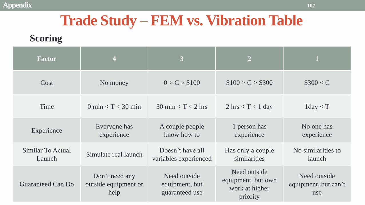
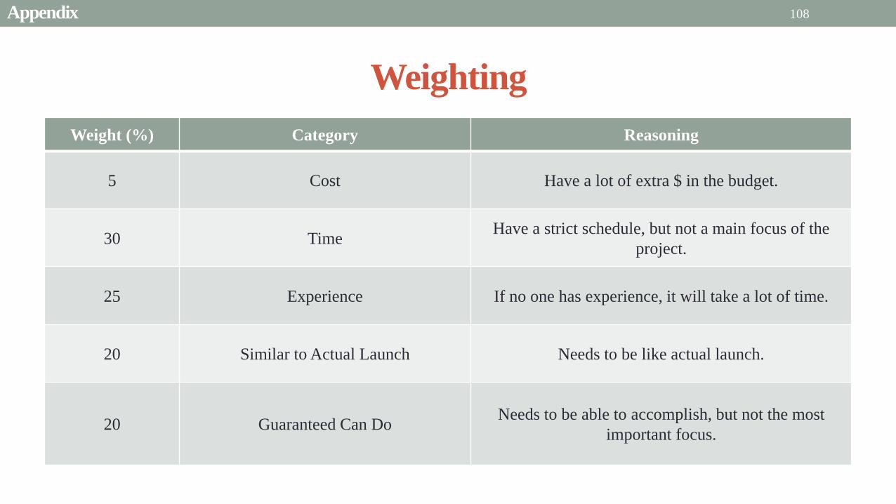
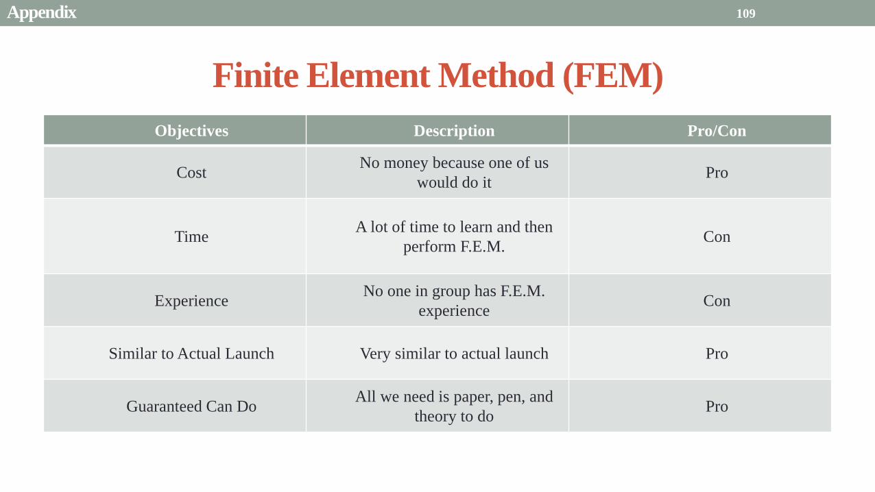
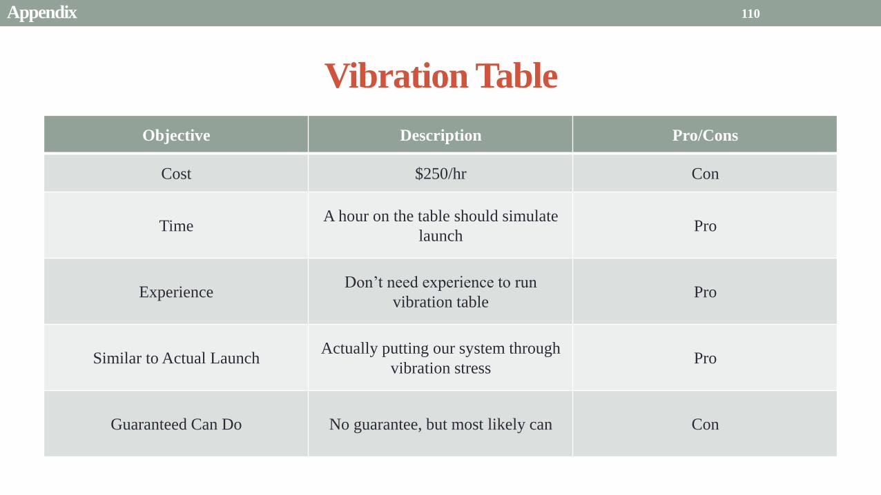
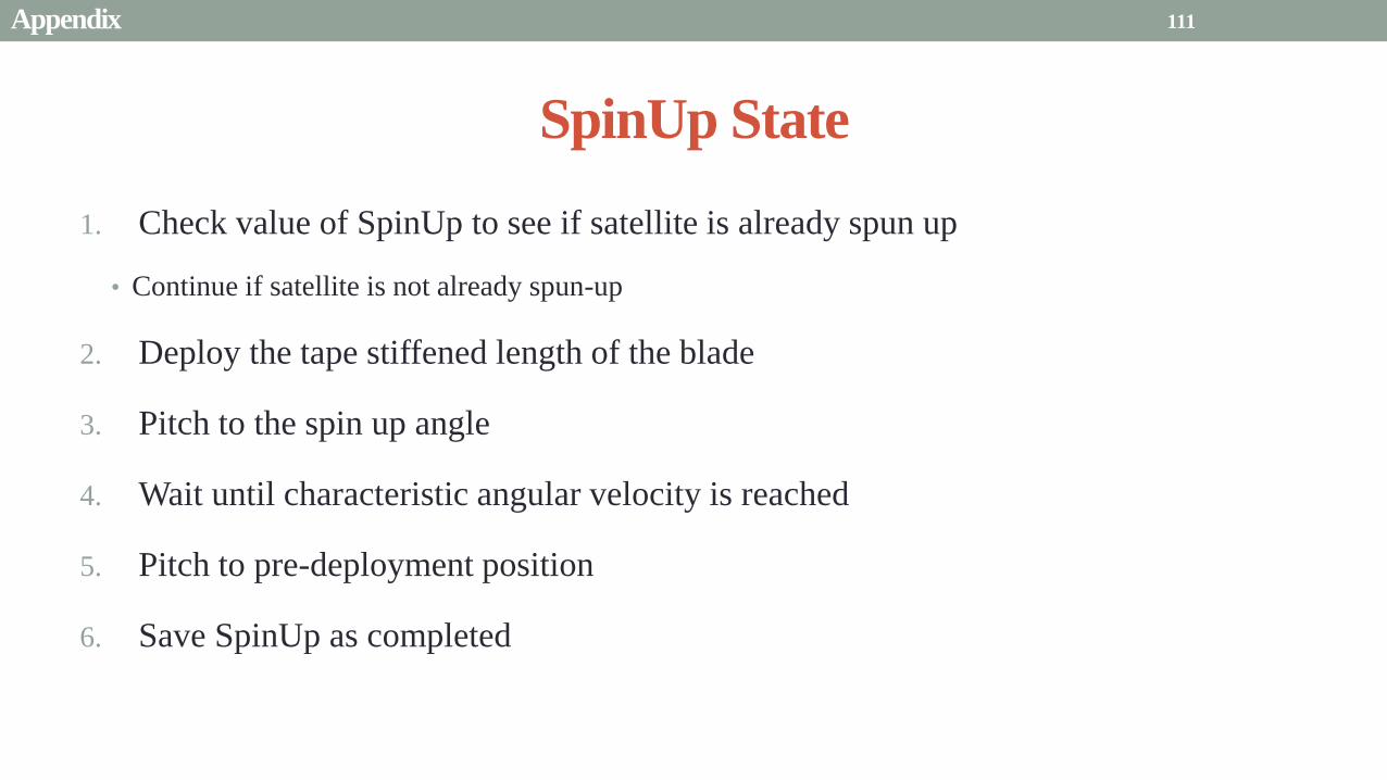
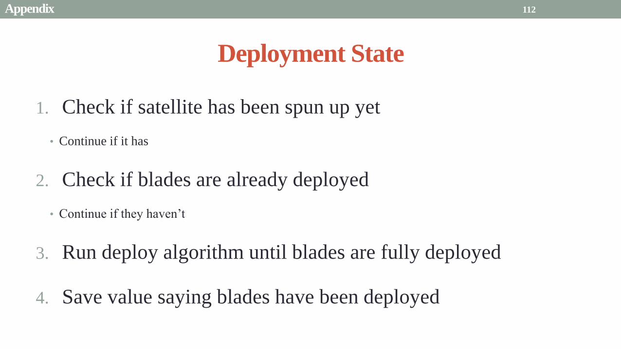
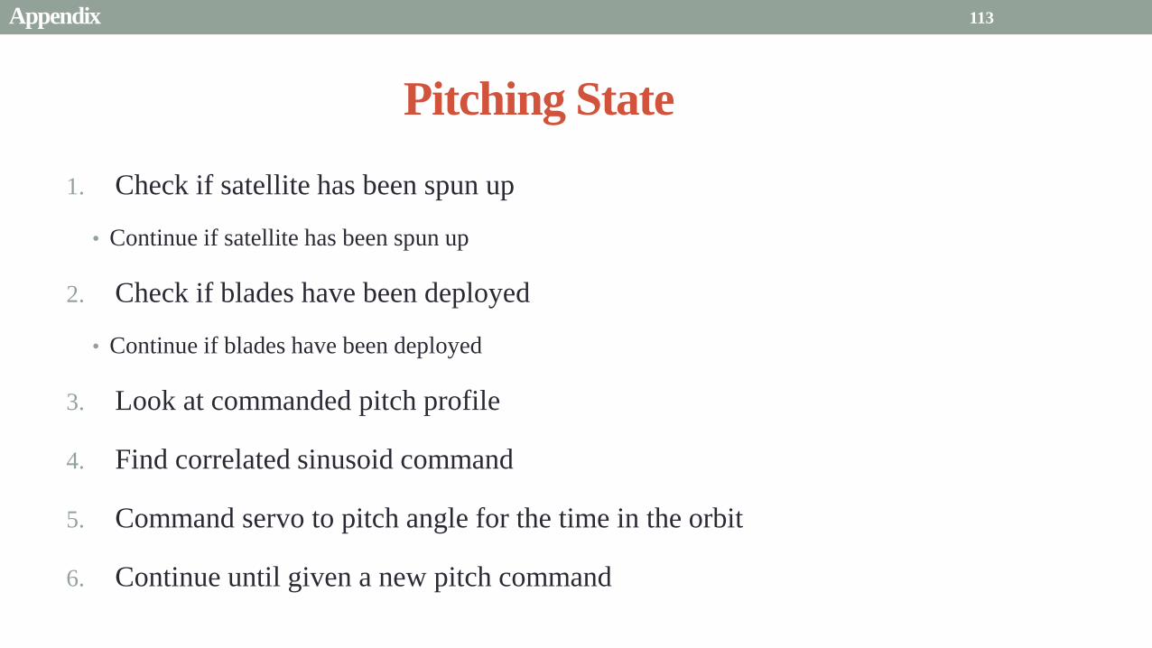
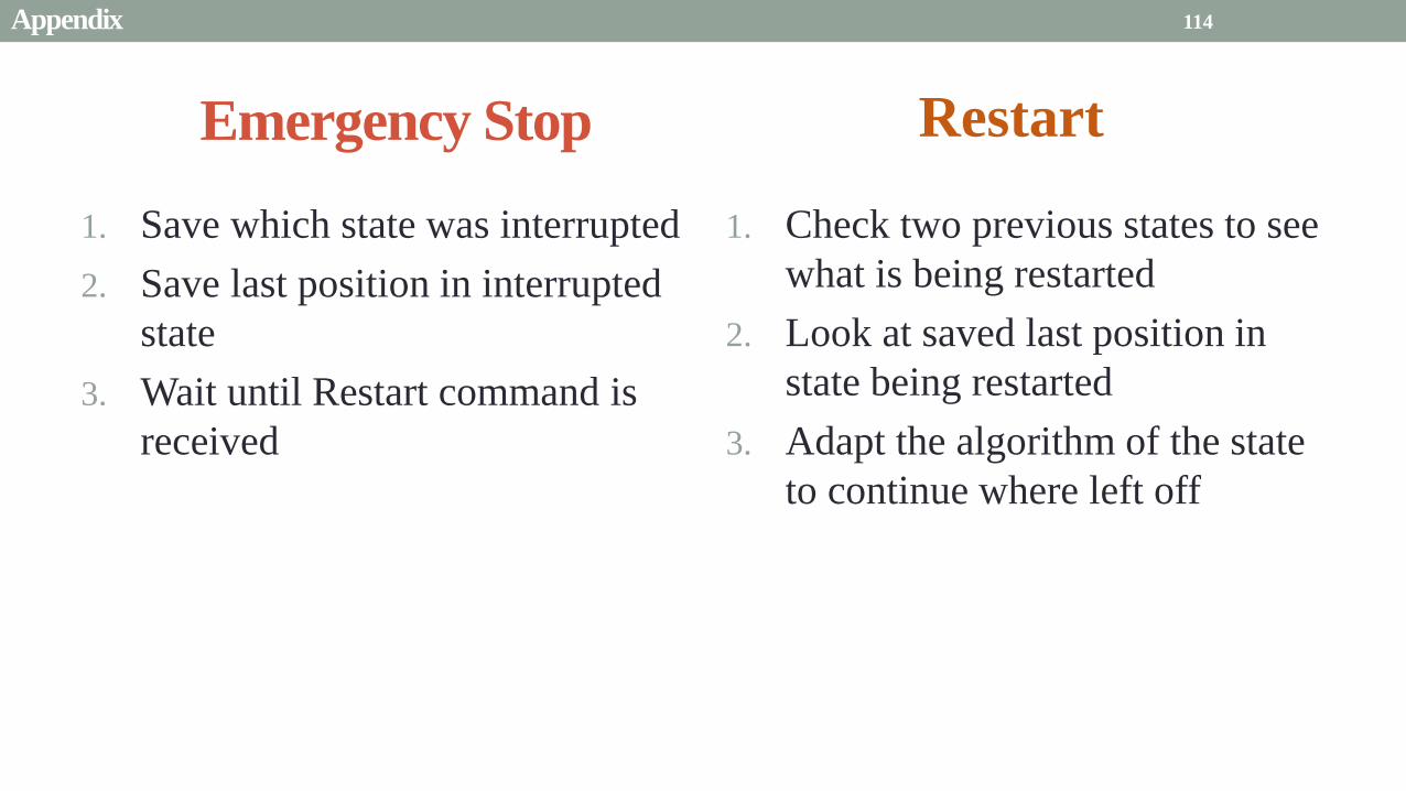
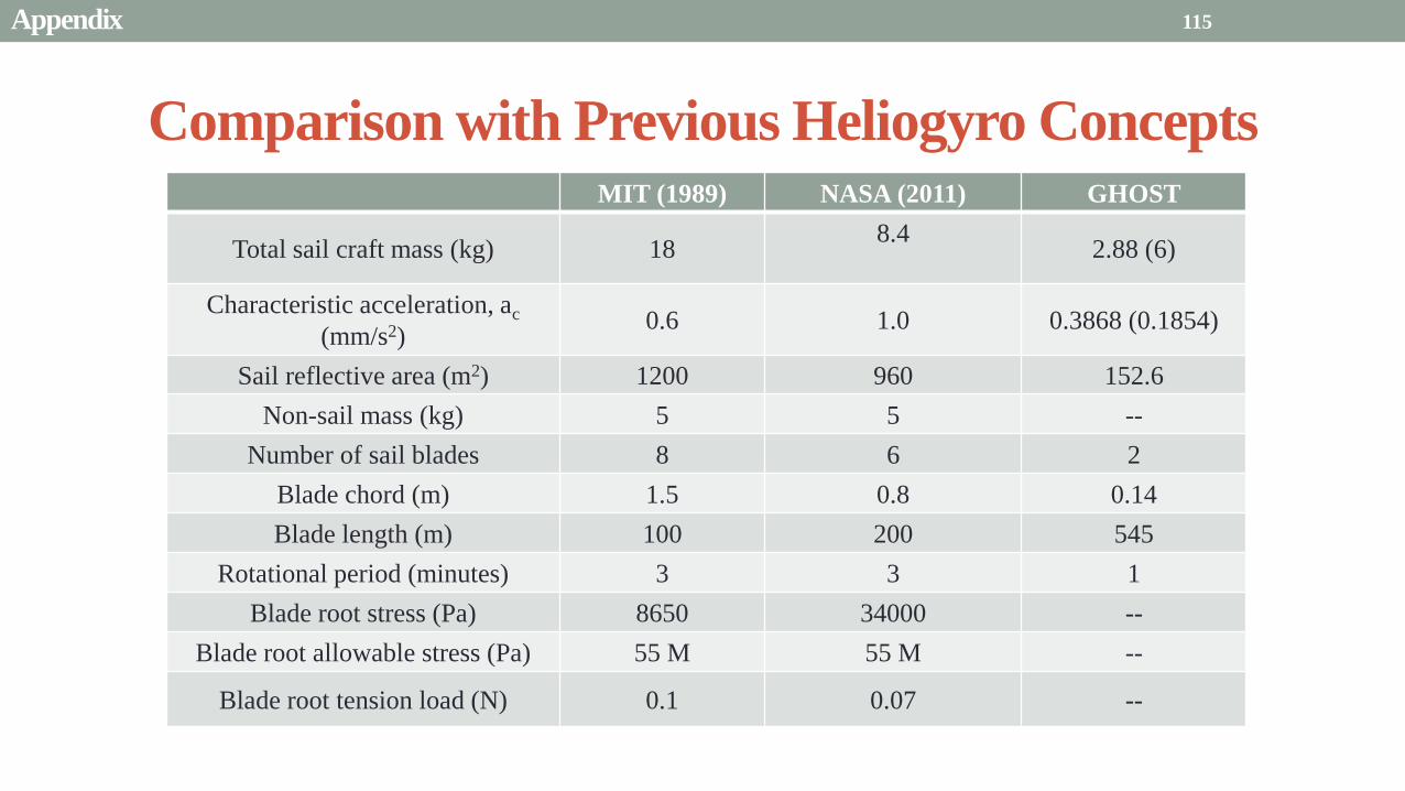