Embed Size (px)
Citation preview
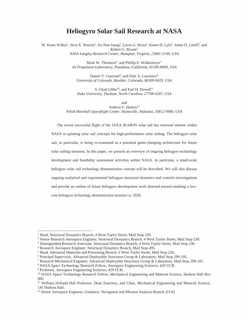
Heliogyro Solar Sail Research at NASA
W. Keats Wilkie1, Jerry E. Warren2, Jer-Nan Juang3, Lucas G. Horta2, Karen H. Lyle2, Justin D. Littell4, and Robert G. Bryant5
NASA Langley Research Center, Hampton, Virginia, 23681-2199, USA
Mark W. Thomson6, and Phillip E. Walkemeyer7 Jet Propulsion Laboratory, Pasadena, California, 91109-8099, USA
Daniel V. Guerrant8, and Dale A. Lawrence9 University of Colorado, Boulder, Colorado, 80309-0429, USA
S. Chad Gibbs10, and Earl H. Dowell11 Duke University, Durham, North Carolina, 27708-0287, USA
and Andrew F. Heaton12
NASA Marshall Spaceflight Center, Huntsville, Alabama, 35812-9900, USA
The recent successful flight of the JAXA IKAROS solar sail has renewed interest within
NASA in spinning solar sail concepts for high-performance solar sailing. The heliogyro solar
sail, in particular, is being re-examined as a potential game-changing architecture for future
solar sailing missions. In this paper, we present an overview of ongoing heliogyro technology
development and feasibility assessment activities within NASA. In particular, a small-scale
heliogyro solar sail technology demonstration concept will be described. We will also discuss
ongoing analytical and experimental heliogyro structural dynamics and controls investigations
and provide an outline of future heliogyro development work directed toward enabling a low-
cost heliogyro technology demonstration mission ca. 2020.
1 Head, Structural Dynamics Branch, 4 West Taylor Street, Mail Stop 230. 2 Senior Research Aerospace Engineer, Structural Dynamics Branch, 4 West Taylor Street, Mail Stop 230. 3 Distinguished Research Associate, Structural Dynamics Branch, 4 West Taylor Street, Mail Stop 230. 4 Research Aerospace Engineer, Structural Dynamics Branch, Mail Stop 495. 5 Head, Advanced Materials and Processing Branch, 6 West Taylor Street, Mail Stop 226. 6 Principal Supervisor, Advanced Deployable Structures Group & Laboratory, Mail Stop 299-101. 7 Research Mechanical Engineer, Advanced Deployable Structures Group & Laboratory, Mail Stop 299-101. 8 NASA Space Technology Research Fellow, Aerospace Engineering Sciences, 429 UCB. 9 Professor, Aerospace Engineering Sciences, 429 UCB. 10 NASA Space Technology Research Fellow, Mechanical Engineering and Material Science, Hudson Hall Box 900 11 William Holland Hall Professor, Dean Emeritus, and Chair, Mechanical Engineering and Material Science, 141 Hudson Hall. 12 Senior Aerospace Engineer, Guidance, Navigation and Mission Analysis Branch, EV42.
I. Introduction
he heliogyro is a helicopter-like, spinning solar sail first introduced by MacNeal in the 1960s.[1] The
heliogyro possesses the primary advantage of a spinning disk sail, namely low weight, while avoiding
many of the difficulties associated with stowage and deployment of large membrane areas. The sail elements of
the heliogyro are long – up to kilometers – high aspect ratio reflective membrane strips. These membrane strips,
or “blades”, spin about a central spacecraft hub and are stiffened by centrifugal forces only, thus making the
design exceedingly light weight. Blades are stowed and deployed from reels; eliminating deployment and
packaging problems associated with handling extremely large, and delicate, membrane sheets used with most
traditional square-rigged or spinning disk solar sail designs. Attitude control is accomplished by pitching the
blades at the root to change their orientation with respect to the sun. This may be performed collectively, to
generate torques about the spin axis, for example to spin up or spin down the heliogyro, or cyclically, in a per-
revolution fashion, to generate thrust components in the plane of rotation. Combinations of collective and cyclic
pitch create overturning moments. Attitude control may thus be accomplished about all six axes using blade
pitch actuation alone.
Despite these compelling advantages, very few heliogyro designs exist in the literature. The most in-depth
heliogyro study, and one of the most detailed studies of any solar sail concept, was that conducted in 1977 by
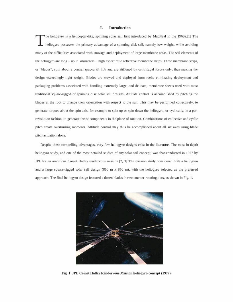
JPL for an ambitious Comet Halley rendezvous mission.[2, 3] The mission study considered both a heliogyro
and a large square-rigged solar sail design (850 m x 850 m), with the heliogyro selected as the preferred
approach. The final heliogyro design featured a dozen blades in two counter-rotating tiers, as shown in Fig. 1.
Fig. 1 JPL Comet Halley Rendezvous Mission heliogyro concept (1977).
T
Each blade was approximately 8 meters wide and 7500 meters long, and packaged would have required the
full cargo bay of the Space Shuttle for launch; which, at that time, was still several years away from flight.
Ultimately, a solar electric propulsion approach was selected over the heliogyro, due primarily to the perceived
overall high risk associated with unproven solar sail technology.[3]
Heliogyro conceptual studies since 1977 have been very rare, with the most notable example a being a small
heliogyro study in 1989 performed by an MIT design team as an entry into a solar sail race to Mars proposed by
the Columbus Quincentenary Commission.[4] The MIT team proposed a very small, 8-bladed, 200 meter
diameter heliogyro. Further heliogyro solar sail development since the MIT study has been almost nonexistent;
the exception being some analytical heliogyro control and dynamics investigations by Blomquist; one of the
original MIT design team members.[5]
The recent successful flight of the JAXA IKAROS solar sail [6] has renewed interest within NASA in
spinning solar sail concepts for high performance solar sailing. The heliogyro solar sail, in particular, is being re-
examined as a potential game-changing architecture for future solar sailing missions.[7] Demonstrating system-
level feasibility of a large, spinning heliogyro on the ground is impossible; however, recent advances in
microsatellite bus technologies for solar sails and other space missions, make an affordable, small-scale
heliogyro technology flight demonstration potentially feasible.[8, 9] However, significant fundamental work in
heliogyro membrane structural dynamics, guidance and control, and solarelastic stability and flutter [10] remains
to be performed before the practicality of a heliogyro flight demonstrator can be determined. In this paper, we
present an overview of recent heliogyro technology development and feasibility assessment activities within, and
sponsored by, NASA. In particular, a small scale, approximately 440-m diameter, heliogyro technology
demonstration concept, serving as a reference for our more detailed dynamics and controls studies, is discussed.
We also give an overview of related ongoing analytical and experimental heliogyro investigations. Lastly, we
provide some recommendations for future heliogyro development work to enable a low-cost, small heliogyro
technology demonstration mission in the near-term, ca. 2020.
II. HELIOS: A Reference Design Concept for Heliogyro Technology Development
HELIOS (High-Performance, Enabling, Low-Cost, Innovative, Operational Solar Sail) is a conceptual, low-
cost, CubeSat-based flight demonstration reference mission for our heliogyro technology development activities.
HELIOS is based upon the 200-m diameter MIT heliogyro concept proposed in 1989 [4], and is designed to be
capable of characteristic accelerations on the order of 0.5 mm/s2 at 1.0 AU; placing it in the range of solar sail
technologies required to enable a variety of science and human exploration support missions.[11] The HELIOS
spacecraft uses modern small-sat and CubeSat technology to minimize bus weight, and is packageable within a
standard Evolved Expendable Launch Vehicle (EELV) Secondary Payload Adaptor (ESPA) rideshare payload
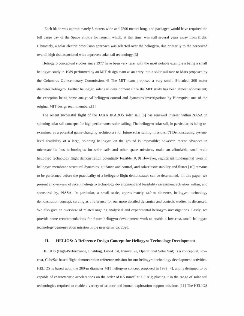
envelope [12] in order to reduce launch costs. The HELIOS heliogyro vehicle, with blade reels, blades, and
videogrammetry camera mast deployed, is shown in Fig. 2. Details of the current HELIOS working concept,
including mission systems and mission design, are described below.
Fig. 2 HELIOS heliogyro technology flight demonstration reference concept. Blades at full deployment are 220 m long. Deployed blade area is 990 m2. Total mass is 18.3 kg.
A. The HELIOS Heliogyro Concept
The primary objectives for the HELIOS reference mission are: 1) validation of heliogyro deployment
technologies; 2) demonstration of controlled heliogyro solar sail flight at mission-enabling characteristic
accelerations, ac, defined here as an ac on the order of 0.5 mm/s2 or more; 3) validation of heliogyro structural
dynamics behavior, including solarelastic stability, and thrust models; and 4) demonstration of orbit changing
capabilities, specifically orbit raising and orbit lowering. These demonstration objectives must further be
accomplished in an affordable manner, which constrains us to design a heliogyro technology demonstration
spacecraft that can be packaged and flown as a low-cost rideshare payload. This also will, most likely, confine us
to operations in a low Earth orbit (LEO), a difficult, but not impossible flight regime for solar sails. To minimize
aerodynamics drag effects, we selected a 1200-1500 km altitude, initially dawn-dusk sun-synchronous orbit as
our best option for a LEO mission. We also desire minimal eclipsing to avoid potential complications of thermal-
elastic transient dynamic effects. A nominal mission duration of approximately four months, with an intentional
de-orbit at mission end-of-life, was also a requirement.
Packaging of the HELIOS heliogyro spacecraft as an ESPA auxiliary payload permits a number of rideshare
launch options, depending on the intended orbit of the primary vehicle. The U.S. Department of Defense Space
Test Program Mission S26 (STP-26) provides a particularly attractive launch scenario, well suited to HELIOS
mission requirements.[13] STP-26 demonstrated a dual-orbit capability using the Hydrazine Auxiliary
Propulsion System (HAPS), which achieved a secondary orbit of 1200 km altitude, which is at the edge of our
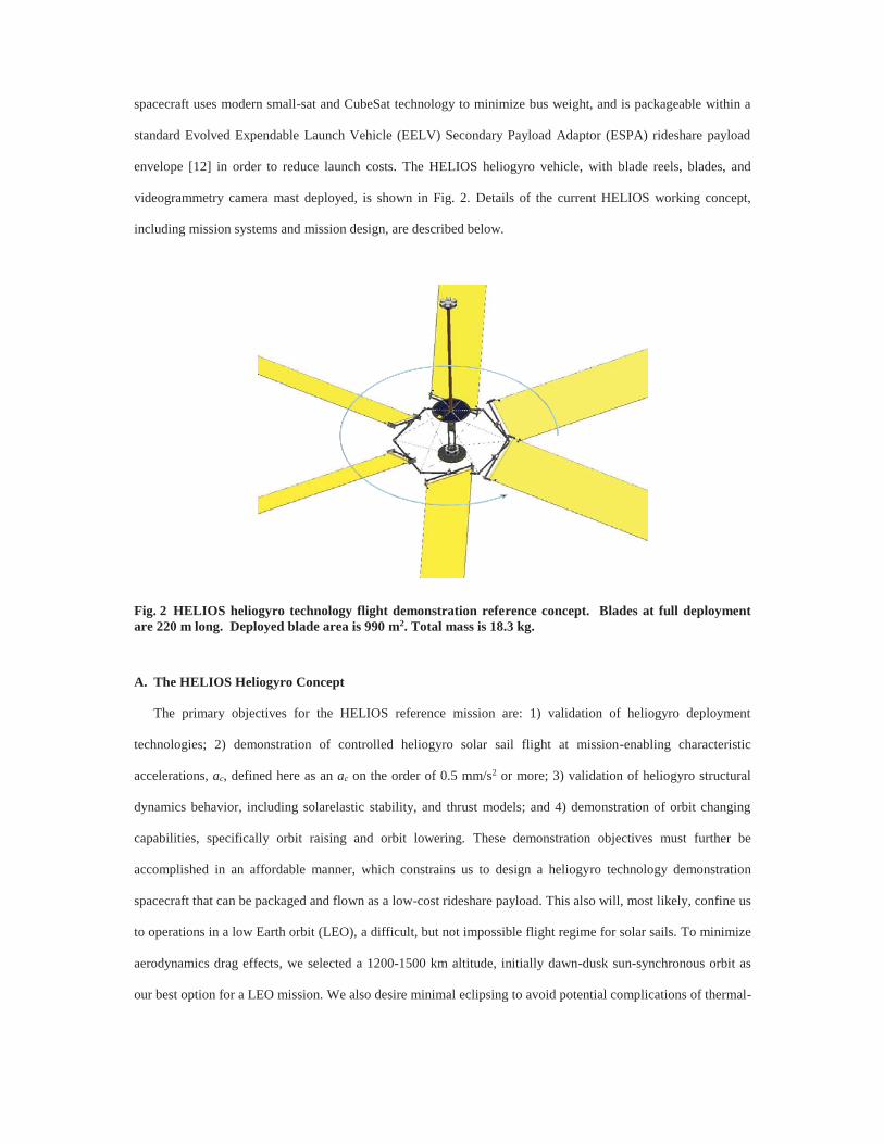
acceptable minimum mission altitude. The stowed HELIOS spacecraft, with ESPA payload envelope indicated,
is shown in a potential launch configuration on a Minotaur IV MPA atop HAPS in Fig. 3.
Fig. 3 HELIOS stowed payload, with potential Minotaur IV HAPS launch configuration shown.
After insertion into orbit, HELIOS separates from the launch vehicle with push-off springs, using a Light
Band separation system, and will be tumbling. The HELIOS spacecraft must first acquire the sun, establish a
sun-pointed attitude, deploy the blade reel hex truss, and spin-up prior to deployment of the sail blade
membranes. The HELIOS spacecraft determines its attitude via sun sensors, providing 4 pi steradian coverage,
and magnetometers. Attitude control of the core vehicle is accomplished using magnetic torque coils with large
loop areas. The blade reel truss must be deployed prior to spin-up to establish the deployed axis of symmetry as
the primary axis, with appropriate margin. The HELIOS deployment sequence is illustrated in Fig. 4.
Because the rotational speed will decrease as the sail deploys due to conservation of angular momentum, the
spin-rate will initially be relatively high; on the order of 5 RPM. Achieving this initial high spin-rate without the
assistance of thrusters could take some time. A mass-efficient approach using magnetic coils, with large loop
HELIOS sail-craft w/ ESPA envelope
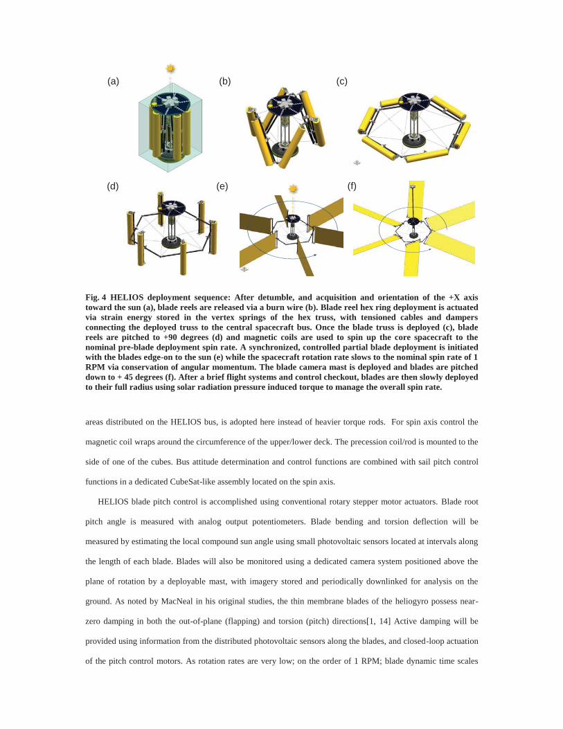
Fig. 4 HELIOS deployment sequence: After detumble, and acquisition and orientation of the +X axis toward the sun (a), blade reels are released via a burn wire (b). Blade reel hex ring deployment is actuated via strain energy stored in the vertex springs of the hex truss, with tensioned cables and dampers connecting the deployed truss to the central spacecraft bus. Once the blade truss is deployed (c), blade reels are pitched to +90 degrees (d) and magnetic coils are used to spin up the core spacecraft to the nominal pre-blade deployment spin rate. A synchronized, controlled partial blade deployment is initiated with the blades edge-on to the sun (e) while the spacecraft rotation rate slows to the nominal spin rate of 1 RPM via conservation of angular momentum. The blade camera mast is deployed and blades are pitched down to + 45 degrees (f). After a brief flight systems and control checkout, blades are then slowly deployed to their full radius using solar radiation pressure induced torque to manage the overall spin rate.
areas distributed on the HELIOS bus, is adopted here instead of heavier torque rods. For spin axis control the
magnetic coil wraps around the circumference of the upper/lower deck. The precession coil/rod is mounted to the
side of one of the cubes. Bus attitude determination and control functions are combined with sail pitch control
functions in a dedicated CubeSat-like assembly located on the spin axis.
HELIOS blade pitch control is accomplished using conventional rotary stepper motor actuators. Blade root
pitch angle is measured with analog output potentiometers. Blade bending and torsion deflection will be
measured by estimating the local compound sun angle using small photovoltaic sensors located at intervals along
the length of each blade. Blades will also be monitored using a dedicated camera system positioned above the
plane of rotation by a deployable mast, with imagery stored and periodically downlinked for analysis on the
ground. As noted by MacNeal in his original studies, the thin membrane blades of the heliogyro possess near-
zero damping in both the out-of-plane (flapping) and torsion (pitch) directions[1, 14] Active damping will be
provided using information from the distributed photovoltaic sensors along the blades, and closed-loop actuation
of the pitch control motors. As rotation rates are very low; on the order of 1 RPM; blade dynamic time scales
(a) (b) (c)
(e)(d) (f)
will be very long and easily within the control bandwidth of the blade root pitch motors. Hub vibration will also
be sensed using a centrally located MEMS 3-axis accelerometer. Blade deployment operations will take place at
very slow rates; on the order of mm/sec. Controlled collective pitching of the blades, to adjust spin rate, will also
take place during deployment. Deployment will be paused periodically to evaluate overall spin balance,
structural dynamics, and flight control characteristics.
HELIOS science data consists of camera images from the six mast-mounted cameras, vibration data from
bus-mounted accelerometers, and time series data from photovoltaic sensors on the sail blades. The data volume
is much larger than most typical CubeSats and the higher orbit required by HELIOS also complicates
communications. Our communications approach is to combine VHF/UHF for all uplink and engineering
downlink and use S-Band for high rate downlink. As the HELIOS bus configuration is not favorable for omni-
directional antennas, antennas will be mounted on both the +X and –X deck faces, with a 3 dB beam-splitter
connecting the two. The S-Band antenna will be a patch antenna, which is commercially available and
compatible with a 1U cube. The VHF/UHF antenna is a pop-up monopole antenna with the deck acting as a
ground plane.
HELIOS power requirement is estimated to be 34 W, which exceeds the largest advertised single CubeSat
power supply, which is capable of 30 W of power. Our approach is to place a separate 20 W supply in each cube.
The solar cells on the +X deck will provide 35 W to 50 W. The –X deck has half the cells of the +X deck in
order to support initial post-separation payload operations. A partial power budget for HELIOS systems is shown
in Table 1.
The estimated nominal HELIOS spacecraft bus mass for all systems exclusive of the sail deployment
mechanisms and sails is 4.5 kg, with a maximum expected mass, including mass contingency, of 5 kg.
Unfortunately, the separation system scar mass, which must remain with the HELIOS sailcraft, is relatively
heavy, at 785 gm. Mass of the sail deployment and pitch control system is also somewhat heavy, at 8.4 kg,
although component masses have not yet been optimized and some mass savings may be achievable in a more
detailed design.
A schematic of the sail membrane assembly is shown in Fig. 5. Each sail blade membrane consists of a 220-
m x 0.75-m x 2.54- m Mylar carrier film metallized on both sides with 0.1 m of aluminum. Aluminized Mylar
was deemed to have acceptable durability for the nominal HELIOS mission environment, based on previous
materials testing performed under the NASA In-Space Propulsion Technology solar sail program.[15] Total
mass allocated for all sail blades, including fittings, battens, tip mass and mass contingency, is 5.0 kg.
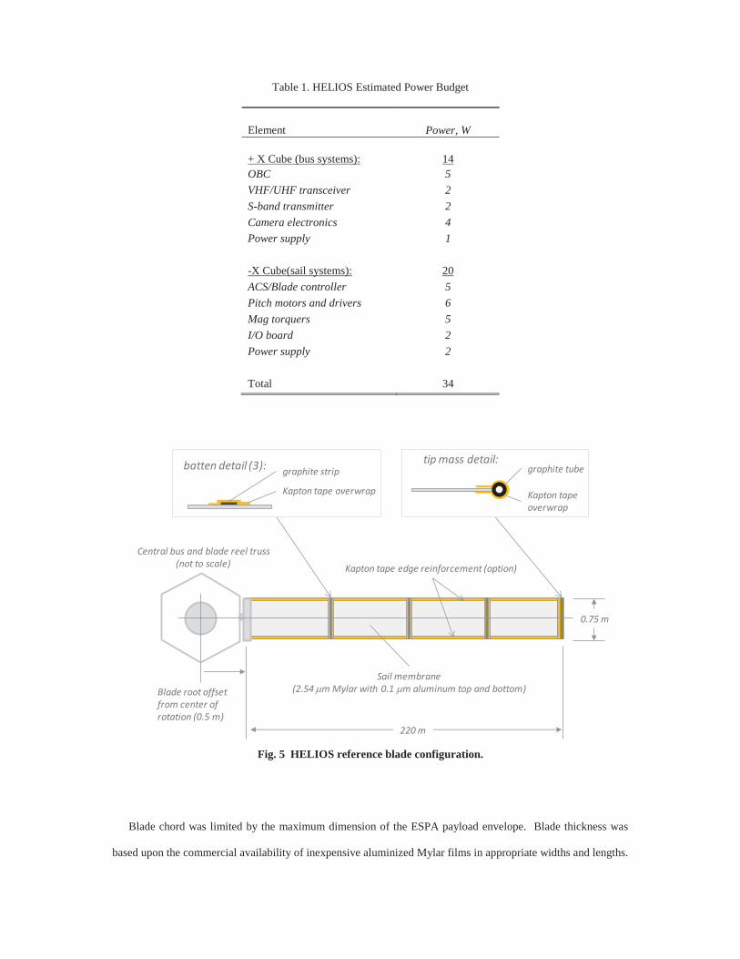
Table 1. HELIOS Estimated Power Budget
Element Power, W + X Cube (bus systems): 14 OBC 5 VHF/UHF transceiver 2 S-band transmitter 2 Camera electronics 4 Power supply 1 -X Cube(sail systems): 20 ACS/Blade controller 5 Pitch motors and drivers 6 Mag torquers 5 I/O board 2 Power supply 2 Total 34
Fig. 5 HELIOS reference blade configuration.
Blade chord was limited by the maximum dimension of the ESPA payload envelope. Blade thickness was
based upon the commercial availability of inexpensive aluminized Mylar films in appropriate widths and lengths.
Blade root offset from center of rotation (0.5 m)
Central bus and blade reel truss(not to scale)
220 m
0.75 m
Kapton tape edge reinforcement (option)
Sail membrane(2.54 m Mylar with 0.1 m aluminum top and bottom)
batten detail (3):
Kapton tape overwrap
graphite striptip mass detail:
Kapton tape overwrap
graphite tube
Blade length was constrained by the available blade stowage volume, blade thickness, and packaging efficiency
of the blades around the blade reels. Three thin battens composed of graphite strips are secured to the membrane
film using Kapton tape at approximately 25% span intervals. The stiff battens provide resistance to chordwise
curling of the blade membranes, which can introduce undesirable solarelastic dynamic responses.[14] Blade tip
weights consist of graphite tubes attached with a 12.5 m Kapton tape overwrap. Kapton tape edge
reinforcements are applied along the blade leading and trailing edges. Edge reinforcements make the blades
more robust to damage and tears in the membranes, and also act to carry the blade centrifugal loads, although,
given the very low centrifugal stresses in the blades, blade designs without edge reinforcement may also be
practical and are also under consideration. Eliminating edge reinforcements could reduce blade weight and
increase packaging efficiency on the blade reels. This could permit longer blades to be stowed within the
existing blade and reel stowage volume, and therefore larger sail areas to be deployed without significant
modifications to the baseline HELIOS sail deployment mechanisms. At full deployment, the HELIOS sail area is
990 m2. Assuming a reflective efficiency of 85%, HELIOS will have a conservative characteristic acceleration
of 0.46 mm/s2 at 1.0 AU, which is reasonably close to our nominal performance goal of 0.5 mm/s2.
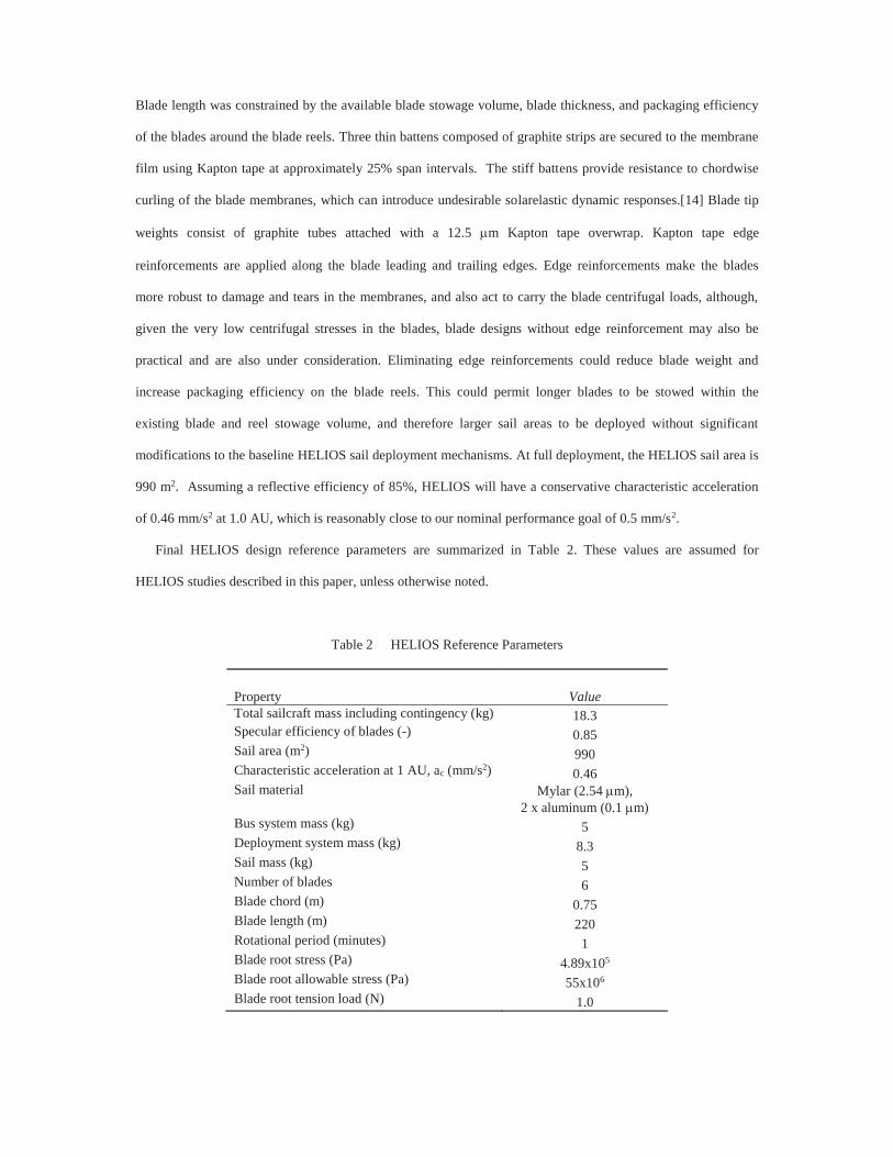
Final HELIOS design reference parameters are summarized in Table 2. These values are assumed for
HELIOS studies described in this paper, unless otherwise noted.
Table 2 HELIOS Reference Parameters
Property Value Total sailcraft mass including contingency (kg) 18.3 Specular efficiency of blades (-) 0.85 Sail area (m2) 990 Characteristic acceleration at 1 AU, ac (mm/s2) 0.46 Sail material Mylar (2.54 m),
2 x aluminum (0.1 m) Bus system mass (kg) 5 Deployment system mass (kg) 8.3 Sail mass (kg) 5 Number of blades 6 Blade chord (m) 0.75 Blade length (m) 220 Rotational period (minutes) 1 Blade root stress (Pa) 4.89x10⁵ Blade root allowable stress (Pa) 55x106 Blade root tension load (N) 1.0
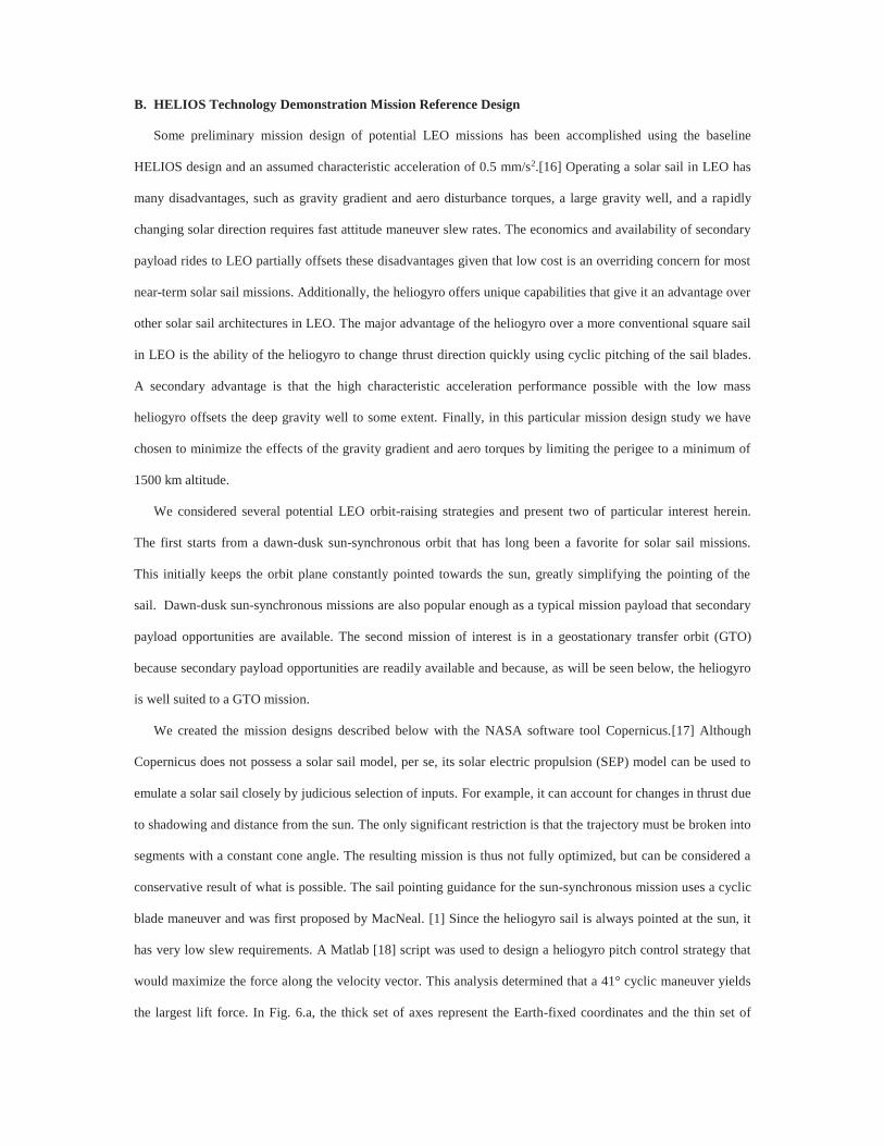
B. HELIOS Technology Demonstration Mission Reference Design
Some preliminary mission design of potential LEO missions has been accomplished using the baseline
HELIOS design and an assumed characteristic acceleration of 0.5 mm/s2.[16] Operating a solar sail in LEO has
many disadvantages, such as gravity gradient and aero disturbance torques, a large gravity well, and a rapidly
changing solar direction requires fast attitude maneuver slew rates. The economics and availability of secondary
payload rides to LEO partially offsets these disadvantages given that low cost is an overriding concern for most
near-term solar sail missions. Additionally, the heliogyro offers unique capabilities that give it an advantage over
other solar sail architectures in LEO. The major advantage of the heliogyro over a more conventional square sail
in LEO is the ability of the heliogyro to change thrust direction quickly using cyclic pitching of the sail blades.
A secondary advantage is that the high characteristic acceleration performance possible with the low mass
heliogyro offsets the deep gravity well to some extent. Finally, in this particular mission design study we have
chosen to minimize the effects of the gravity gradient and aero torques by limiting the perigee to a minimum of
1500 km altitude.
We considered several potential LEO orbit-raising strategies and present two of particular interest herein.
The first starts from a dawn-dusk sun-synchronous orbit that has long been a favorite for solar sail missions.
This initially keeps the orbit plane constantly pointed towards the sun, greatly simplifying the pointing of the
sail. Dawn-dusk sun-synchronous missions are also popular enough as a typical mission payload that secondary
payload opportunities are available. The second mission of interest is in a geostationary transfer orbit (GTO)
because secondary payload opportunities are readily available and because, as will be seen below, the heliogyro
is well suited to a GTO mission.
We created the mission designs described below with the NASA software tool Copernicus.[17] Although
Copernicus does not possess a solar sail model, per se, its solar electric propulsion (SEP) model can be used to
emulate a solar sail closely by judicious selection of inputs. For example, it can account for changes in thrust due
to shadowing and distance from the sun. The only significant restriction is that the trajectory must be broken into
segments with a constant cone angle. The resulting mission is thus not fully optimized, but can be considered a
conservative result of what is possible. The sail pointing guidance for the sun-synchronous mission uses a cyclic
blade maneuver and was first proposed by MacNeal. [1] Since the heliogyro sail is always pointed at the sun, it
has very low slew requirements. A Matlab [18] script was used to design a heliogyro pitch control strategy that
would maximize the force along the velocity vector. This analysis determined that a 41° cyclic maneuver yields
the largest lift force. In Fig. 6.a, the thick set of axes represent the Earth-fixed coordinates and the thin set of
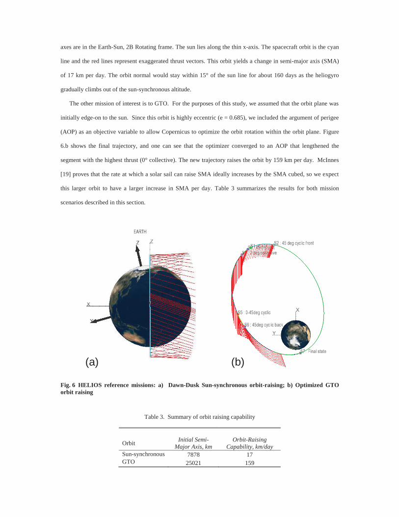
axes are in the Earth-Sun, 2B Rotating frame. The sun lies along the thin x-axis. The spacecraft orbit is the cyan
line and the red lines represent exaggerated thrust vectors. This orbit yields a change in semi-major axis (SMA)
of 17 km per day. The orbit normal would stay within 15° of the sun line for about 160 days as the heliogyro
gradually climbs out of the sun-synchronous altitude.
The other mission of interest is to GTO. For the purposes of this study, we assumed that the orbit plane was
initially edge-on to the sun. Since this orbit is highly eccentric (e = 0.685), we included the argument of perigee
(AOP) as an objective variable to allow Copernicus to optimize the orbit rotation within the orbit plane. Figure
6.b shows the final trajectory, and one can see that the optimizer converged to an AOP that lengthened the
segment with the highest thrust (0° collective). The new trajectory raises the orbit by 159 km per day. McInnes
[19] proves that the rate at which a solar sail can raise SMA ideally increases by the SMA cubed, so we expect
this larger orbit to have a larger increase in SMA per day. Table 3 summarizes the results for both mission
scenarios described in this section.
Fig. 6 HELIOS reference missions: a) Dawn-Dusk Sun-synchronous orbit-raising; b) Optimized GTO orbit raising
Table 3. Summary of orbit raising capability
Orbit Initial Semi-Major Axis, km
Orbit-Raising Capability, km/day
Sun-synchronous 7878 17 GTO 25021 159
(a) (b)
Both of these preliminary mission designs are viable candidates for a HELIOS heliogyro mission. The sun-
synchronous orbit employs a much simpler control scheme using only one continuous maneuver. The GTO
mission option would demonstrate orbit-raising more quickly and has the longest time-scales, which could also
simplify flight validation operations.
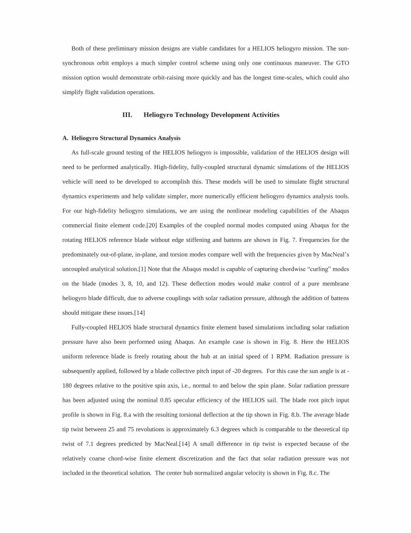
III. Heliogyro Technology Development Activities
A. Heliogyro Structural Dynamics Analysis
As full-scale ground testing of the HELIOS heliogyro is impossible, validation of the HELIOS design will
need to be performed analytically. High-fidelity, fully-coupled structural dynamic simulations of the HELIOS
vehicle will need to be developed to accomplish this. These models will be used to simulate flight structural
dynamics experiments and help validate simpler, more numerically efficient heliogyro dynamics analysis tools.
For our high-fidelity heliogyro simulations, we are using the nonlinear modeling capabilities of the Abaqus
commercial finite element code.[20] Examples of the coupled normal modes computed using Abaqus for the
rotating HELIOS reference blade without edge stiffening and battens are shown in Fig. 7. Frequencies for the
predominately out-of-plane, in-plane, and torsion modes compare well with the frequencies given by MacNeal’s
uncoupled analytical solution.[1] Note that the Abaqus model is capable of capturing chordwise “curling” modes
on the blade (modes 3, 8, 10, and 12). These deflection modes would make control of a pure membrane
heliogyro blade difficult, due to adverse couplings with solar radiation pressure, although the addition of battens
should mitigate these issues.[14]
Fully-coupled HELIOS blade structural dynamics finite element based simulations including solar radiation
pressure have also been performed using Abaqus. An example case is shown in Fig. 8. Here the HELIOS
uniform reference blade is freely rotating about the hub at an initial speed of 1 RPM. Radiation pressure is
subsequently applied, followed by a blade collective pitch input of -20 degrees. For this case the sun angle is at -
180 degrees relative to the positive spin axis, i.e., normal to and below the spin plane. Solar radiation pressure
has been adjusted using the nominal 0.85 specular efficiency of the HELIOS sail. The blade root pitch input
profile is shown in Fig. 8.a with the resulting torsional deflection at the tip shown in Fig. 8.b. The average blade
tip twist between 25 and 75 revolutions is approximately 6.3 degrees which is comparable to the theoretical tip
twist of 7.1 degrees predicted by MacNeal.[14] A small difference in tip twist is expected because of the
relatively coarse chord-wise finite element discretization and the fact that solar radiation pressure was not
included in the theoretical solution. The center hub normalized angular velocity is shown in Fig. 8.c. The
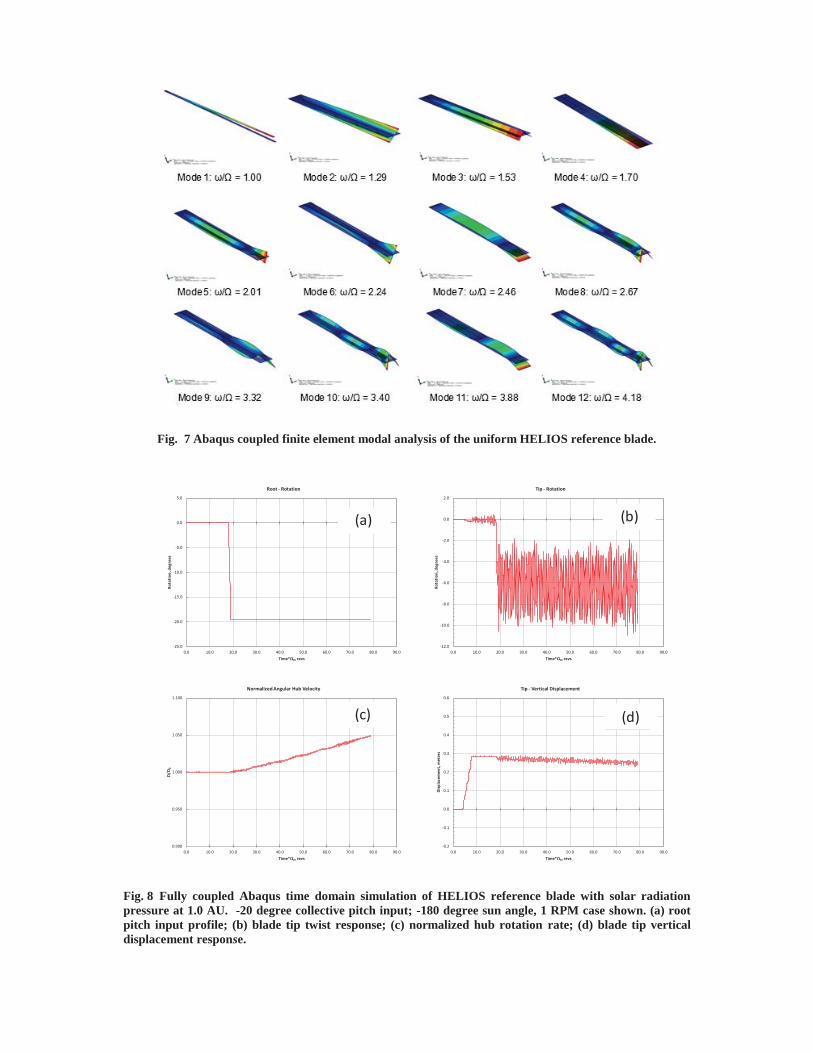
Fig. 7 Abaqus coupled finite element modal analysis of the uniform HELIOS reference blade.
Fig. 8 Fully coupled Abaqus time domain simulation of HELIOS reference blade with solar radiation pressure at 1.0 AU. -20 degree collective pitch input; -180 degree sun angle, 1 RPM case shown. (a) root pitch input profile; (b) blade tip twist response; (c) normalized hub rotation rate; (d) blade tip vertical displacement response.
0.900
0.950
1.000
1.050
1.100
0.0 10.0 20.0 30.0 40.0 50.0 60.0 70.0 80.0 90.0
Ω/Ω
0
Time*Ω0, revs
Normalized Angular Hub Velocity
pbar = 0.00094
-12.0
-10.0
-8.0
-6.0
-4.0
-2.0
0.0
2.0
0.0 10.0 20.0 30.0 40.0 50.0 60.0 70.0 80.0 90.0
Rota
tion,
deg
rees
Time*Ω0, revs
Tip - Rotation
pbar = 0.00094
-0.2
-0.1
0.0
0.1
0.2
0.3
0.4
0.5
0.6
0.0 10.0 20.0 30.0 40.0 50.0 60.0 70.0 80.0 90.0
Disp
lace
men
t, m
eter
s
Time*Ω0, revs
Tip - Vertical Displacement
pbar = 0.00094
-25.0
-20.0
-15.0
-10.0
-5.0
0.0
5.0
0.0 10.0 20.0 30.0 40.0 50.0 60.0 70.0 80.0 90.0
Rota
tion,
deg
rees
Time*Ω0, revs
Root - Rotation
pbar = 0.00094(a) (b)
(c) (d)
angular velocity increases as the blade is pitched due to the resulting solar radiation pressure induced torque
about the spin axis. This is expected since the blade is freely spinning as it would be in flight. The average blade
tip vertical displacement is shown in Fig. 8.d. The average blade tip vertical displacement before application of
the root pitch input is approximately 0.286 meters which compares with the theoretical displacement of 0.281
meters.[1] Blade vertical deflection decreases over time as the blade and hub rotation rate, and resulting
centrifugal forces, increase. Future studies will include nonuniform blade features and examine sensitivities of
the finite element mesh discretization in more detail.
B. Heliogyro Flutter and Solarelastic Stability Studies
Heliogyro dynamics and solarelastic stability studies are possible using the fully-coupled, finite element
analysis methods described above, although these simulations are computationally expensive and more efficient
heliogyro analytical tools appropriate for rapid design and trade studies are needed. Our approach [21],
previously explored by Natori [22], adapts rotating beam equations of motion developed for conventional
helicopter rotor blade analysis [23] for use with the heliogyro. These equations can be numerically solved using
MATLAB-based codes, and although not applicable to all heliogyro flight conditions, can be used to evaluate
heliogyro structural dynamic and stability behavior for many restricted, yet still relevant, cases. One such case is
for a heliogyro operating at zero blade pitch angle with the spin axis pointed toward the sun. For this case, the
equations of motion can be transformed into a second-order set of ordinary differential equations with constant
coefficients valid for small dynamic deflections. The eigenvalues of this system can be evaluated as a function of
fixed rotational speed and incident solar radiation pressure to determine operational stability boundaries for a
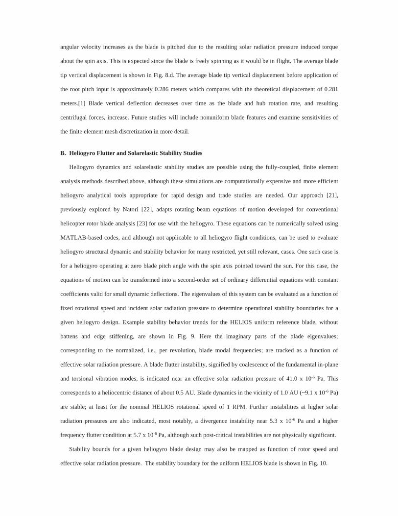
given heliogyro design. Example stability behavior trends for the HELIOS uniform reference blade, without
battens and edge stiffening, are shown in Fig. 9. Here the imaginary parts of the blade eigenvalues;
corresponding to the normalized, i.e., per revolution, blade modal frequencies; are tracked as a function of
effective solar radiation pressure. A blade flutter instability, signified by coalescence of the fundamental in-plane
and torsional vibration modes, is indicated near an effective solar radiation pressure of 41.0 x 10⁻⁶ Pa. This
corresponds to a heliocentric distance of about 0.5 AU. Blade dynamics in the vicinity of 1.0 AU (~9.1 x 10⁻⁶ Pa)
are stable; at least for the nominal HELIOS rotational speed of 1 RPM. Further instabilities at higher solar
radiation pressures are also indicated, most notably, a divergence instability near 5.3 x 10⁻⁶ Pa and a higher
frequency flutter condition at 5.7 x 10⁻⁶ Pa, although such post-critical instabilities are not physically significant.
Stability bounds for a given heliogyro blade design may also be mapped as function of rotor speed and
effective solar radiation pressure. The stability boundary for the uniform HELIOS blade is shown in Fig. 10.
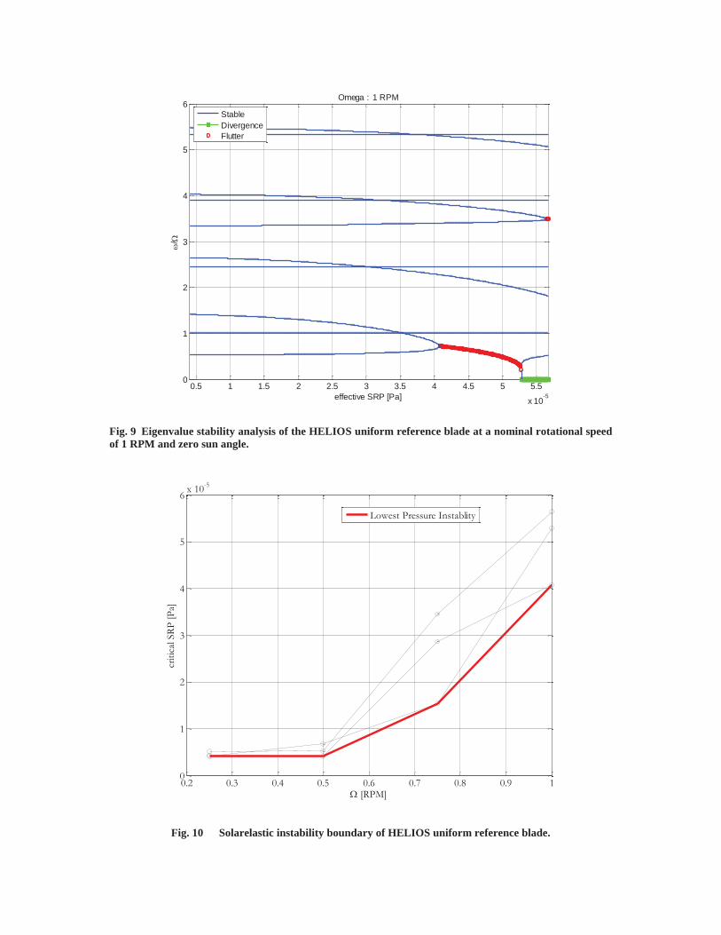
Fig. 9 Eigenvalue stability analysis of the HELIOS uniform reference blade at a nominal rotational speed of 1 RPM and zero sun angle.
Fig. 10 Solarelastic instability boundary of HELIOS uniform reference blade.
0.5 1 1.5 2 2.5 3 3.5 4 4.5 5 5.5
x 10-5
0
1
2
3
4
5
6 Omega : 1 RPM
effective SRP [Pa]
/
StableDivergenceFlutter
0.2 0.3 0.4 0.5 0.6 0.7 0.8 0.9 10
1
2
3
4
5
6 x 10⁻⁵
[RPM]
criti
cal S
RP [P
a]
Lowest Pressure Instablity
Here, all unstable eigenvalues over the rotor speed range indicated have been tracked with the critical radiation
pressure required to induce instability plotted against rotor speed. The lower bound in radiation pressure is
indicated by the thick red line, with stable regions of rotational speed and radiation pressure lying below the line.
Examination of this stability boundary plot indicates that at 1.0 AU solar radiation pressures (9.1 x 10⁻⁶ Pa) the
HELIOS blade will encounter a solarelastic instability when rotational speed drops below approximately 0.6
RPM. Experimental verification of solarelastic stability characteristics would actually be an important goal of a
heliogyro flight technology demonstration mission.[24] In practice, this could be accomplished by gradually
reducing heliogyro rotation speed through the application of blade collective pitch; pausing periodically to
experimentally evaluate the sub-critical changes in blade modal frequencies. As the dynamics of the heliogyro
are relatively slow in real-time, stability boundaries may be approached slowly, and backed away from relatively
quickly by re-application of blade collective pitch to increase the vehicle spin rate.
C. Ground Validation Experiments
Membrane structural damping will have a significant effect on all the dynamics of heliogyro blades, and
reliable membrane damping estimates will be critical for designing the heliogyro blade control and damping
augmentation systems. Although membrane damping is expected to be very small, even a small energy
dissipation capability could be sufficiently stabilizing for many heliogyro blade vibration modes, particularly
higher-order elastic modes which may cause undesirable narrow band instabilities at certain rotational speeds.
To better understand and characterize damping mechanisms for very lightly loaded membranes, a series of
modal tests on small-scale membrane blade test specimens were performed under 1 g in a vacuum chamber.[25]
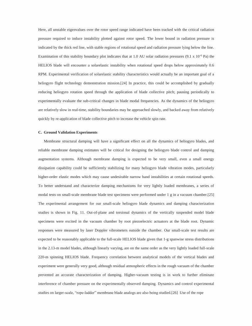
The experimental arrangement for our small-scale heliogyro blade dynamics and damping characterization
studies is shown in Fig. 11. Out-of-plane and torsional dynamics of the vertically suspended model blade
specimens were excited in the vacuum chamber by root piezoelectric actuators at the blade root. Dynamic
responses were measured by laser Doppler vibrometers outside the chamber. Our small-scale test results are
expected to be reasonably applicable to the full-scale HELIOS blade given that 1-g spanwise stress distributions
in the 2.13-m model blades, although linearly varying, are on the same order as the very lightly loaded full-scale
220-m spinning HELIOS blade. Frequency correlation between analytical models of the vertical blades and
experiment were generally very good, although residual atmospheric effects in the rough vacuum of the chamber
prevented an accurate characterization of damping. Higher-vacuum testing is in work to further eliminate
interference of chamber pressure on the experimentally observed damping. Dynamics and control experimental
studies on larger-scale, “rope-ladder” membrane blade analogs are also being studied.[26] Use of the rope
Fig. 11 1-g vertical membrane dynamics testing in 2.5 m vacuum sphere.
ladder models, which closely emulate the dynamics of membranes, permits us to conduct many structural
dynamics and control experiments on blade-like structures in air, and at scales larger than those possible in our
available vacuum chambers.
Although exact dynamic similitude with full-scale spinning heliogyros, including solar radiation pressure
effects, is not possible on the ground due to the presence of gravity, analytical models of the sub-scale spinning
membrane system at one-g can be validated and used to build confidence in analytical simulations of the full-
scale vehicle. Such experiments were proposed during the JPL heliogyro study of the 1970s, although no
experiments were performed,[27] and earlier heliogyro spin dynamics validation experiments attempted in air by
MacNeal were severely complicated by atmospheric effects.[14] As an inexpensive pathfinder experiment, we
have recently begun testing small-scale spinning membrane blades in our 2.5-m diameter vacuum sphere using a
system constructed around low-cost, commercially available radio-controlled helicopter components. Fig. 12
shows the spin test apparatus in the vacuum chamber during initial testing.
The entire assembly is mounted upside-down to prohibit the blades from wrapping around the drive system
during spin up. A hub-mounted videogrammetry camera system is used to recover displacement information
from the spinning membrane blades. Post-test processing of the rotating system camera imagery using
commercial videogrammetry software is now underway. Further calibration of the camera system should
increase contrast and improve our ability to extract deflection time histories for the retroreflective targets located
Piezoelectric Actuator
(bending or torsion)
2.13 m vertically suspended blade
test article
Scanning Laser Doppler Vibrometer
(SLDV)
SLDV field of view
Retro- reflective targets
Observation ports (x3)
Single-point Laser Doppler
Vibrometers (x2)
2.5 m Vacuum Sphere
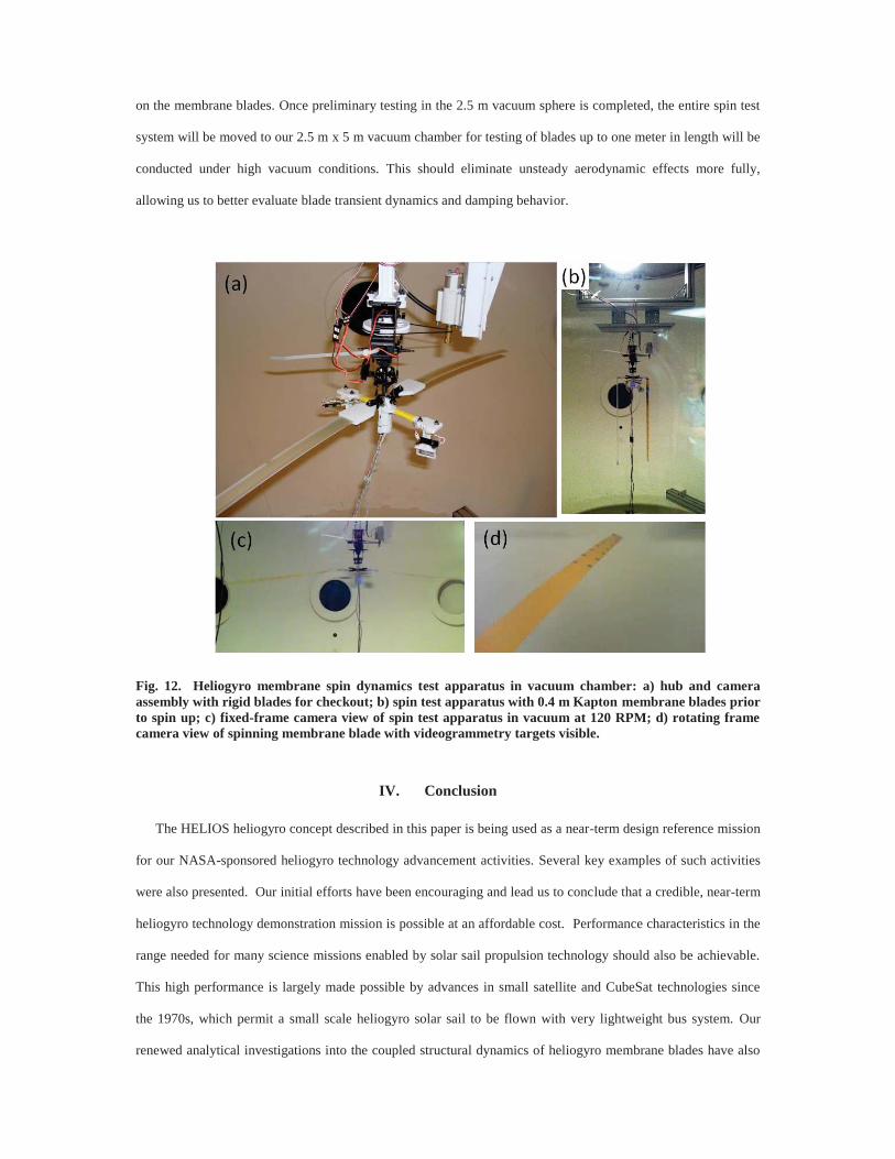
on the membrane blades. Once preliminary testing in the 2.5 m vacuum sphere is completed, the entire spin test
system will be moved to our 2.5 m x 5 m vacuum chamber for testing of blades up to one meter in length will be
conducted under high vacuum conditions. This should eliminate unsteady aerodynamic effects more fully,
allowing us to better evaluate blade transient dynamics and damping behavior.
Fig. 12. Heliogyro membrane spin dynamics test apparatus in vacuum chamber: a) hub and camera assembly with rigid blades for checkout; b) spin test apparatus with 0.4 m Kapton membrane blades prior to spin up; c) fixed-frame camera view of spin test apparatus in vacuum at 120 RPM; d) rotating frame camera view of spinning membrane blade with videogrammetry targets visible.
IV. Conclusion
The HELIOS heliogyro concept described in this paper is being used as a near-term design reference mission
for our NASA-sponsored heliogyro technology advancement activities. Several key examples of such activities
were also presented. Our initial efforts have been encouraging and lead us to conclude that a credible, near-term
heliogyro technology demonstration mission is possible at an affordable cost. Performance characteristics in the
range needed for many science missions enabled by solar sail propulsion technology should also be achievable.
This high performance is largely made possible by advances in small satellite and CubeSat technologies since
the 1970s, which permit a small scale heliogyro solar sail to be flown with very lightweight bus system. Our
renewed analytical investigations into the coupled structural dynamics of heliogyro membrane blades have also
revealed no intractable stability and control issues, although to what degree major damping augmentation
systems will be needed to ensure solarelastic stability and damping of blade transient responses remains a subject
for future work.
Also the subject of future work is the development of higher-fidelity blade deployment mechanisms.
Development of these systems to high technology readiness levels should be possible with standard flight
systems engineering practices and well designed ground tests. High altitude, balloon tests could also be used to
experimentally validate deployment reel mechanisms at HELIOS-like full-scales, although without rotational
dynamics. Ultimately, an actual spaceflight validation mission will be needed to prove feasibility of the
heliogyro solar sail concept and retire risk. Fortunately, this appears possible at an affordable, non-flagship
mission cost. Given a near term effort to advance the technology readiness of critical systems, most notably
blade dynamics simulation capabilities, deployment mechanisms, solarelastic flutter dynamics and control
systems including damping augmentation, and relevant ground test demonstrations, a HELIOS or HELIOS-like,
low-cost heliogyro flight demonstration could be ready for launch in as few as five years.
Acknowledgments
The authors wish to thank the following individuals for their technical assistance and support with this
project: P. Douglas Lisman (JPL), Thomas Cleckner (Governor’s School, Hampton, VA), Christopher Savage
(NASA, LaRC), R. Wayne Matthews (NASA, LaRC), Thomas Walker (NASA, LaRC), Joel Alexa (NASA,
LaRC), Jack Lu (National Institute of Aerospace), Christina Wilson (Wichita State University), and John
Thomson (San Diego State University).
References
[1] MacNeal, R., “The Heliogyro: An Interplanetary Flying Machine,” NASA Contractor Report CR 84460, June 1967.
[2] Friedman, L., “Solar Sailing Development Program (FY 1977) Final Report Vol I”, Report 720-9, Jet Propulsion
Laboratory, January 30, 1978.
[3] MacNeal, R. H., Hedgepeth, J. M., “Helicopters for Interplanetary Space Flight,” 34th National Forum of the American
Helicopter Society, Washington, D. C., May 1978.
[4] Blomquist, R., “Design Study of a Solid-State Heliogyro Solar Sail,” M.S. thesis, Massachusetts Institute of Technology,
Cambridge, MA, September 1990.
[5] Blomquist, R., “Heliogyro Control,” Ph.D. dissertation, Carnegie Mellon University, Pittsburgh, PA, 2009.
[6] Mori, O., et al., “World’s First Demonstration of Solar Power Sailing by IKAROS,” in: Vazquez-Poritz, J.F. (Ed.),
Abstracts of the Second International Symposium on Solar Sailing, New York, USA, 20–22 July, 2010, pp. 19–20, 2010.
[7] Wilkie, W., et al. “The Heliogyro Reloaded.” JANNAF 5th Spacecraft Propulsion Subcommittee Joint Meeting,
December 2011.
[8] Lappas, V., et al., “CubeSail: A Low Cost CubeSat Based Solar Sail Demonstration Mission,” Advances in Space
Research, 48 (2011) 1890–1901.
[9] Johnson, L., et al., “NanoSail-D: A Solar Sail Demonstration Mission,” Acta Astronautica, 68 (2011) 571-575.
[10] Dowell, E., “Can Solar Sails Flutter?,” AIAA Journal, Vol. 49 (2011) 1305-1307.
[11] Macdonald, M., McInnes, C., “Solar Sail Science Mission Applications and Advancement,” Advances in Space
Research, 48 (2011) 1702–1716.
[12] Evolved Expendable Launch Vehicle Secondary Payload Adapter Rideshare Users Guide (ESPA RUG), May 2010.
[13] Borowski, H., et al., “Responsive Access to Space: Space Test Program Mission S26,” IEEE Aerospace Conference,
paper #1220, January 2009.
[14] MacNeal, R. H., “Structural Dynamics of the Heliogyro,” NASA CR-17445A, 1971.
[15] Edwards, D., Hovater, M., Hubbs, W., et al., “Characterization of Candidate Solar Sail Material Exposed to Space
Environmental Effects,” 42nd AIAA Aerospace Sciences Meeting and Exhibit, AIAA 2004-1085, Jan. 2004.
[16] Guerrant, D., Lawrence, D., Heaton, A., “Earth-Escape Capabilities of the Heliogyro Solar Sail,” to be presented at
AAS/AIAA Astrodynamics Specialist Conference, Hilton Head, SC, August 2013.
[17] http://www.nasa.gov/centers/johnson/techtransfer/technology/MSC-24209-1-copernicus.html
[18] The Mathworks, Inc., Natick, MA, USA.
[19] McInnes, Colin R., Solar Sailing: Technology, Dynamics and Mission Applications, 1st ed., Springer-Praxis,
Chichester, UK, 1999.
[20] Dassault Systèmes Simulia Corp., Providence, RI, USA.
[21] Gibbs, S., Dowell, E., “Solarelastic Stability of the Heliogyro,” to be presented at the Third International Symposium
on Solar Sailing, Glasgow, UK, June 2013.
[22] Natori, M., Nemat-Nasser, S., Mitsugi, J., “Instability of a Rotating Blade Subjected to Solar Radiation Pressure,”
AIAA 30th Structures, Structural Dynamics and Materials Conference, April 1989.
[23] Hodges, D., Dowell, E., “Nonlinear Equations of Motion for the Elastic Bending and Torsion of Twisted Nonuniform
Rotor Blades,” NASA TN D-7818, December 1974.
[24] “Heliogyro Preliminary Design, Phase II Final Report,” NASA Contractor Report CR-157128, January, 1978.
[25] Gibbs, S., Guerrant, D., Wilkie, W., Dowell, E., “Rectangular Solar Sail Flutter,” presented at the 54th AIAA
Structures, Dynamics, and Materials Conference, Boston, MA, April 2013.
[26] Huang, Y., Juang, J., Hung, C., Wilkie, W., “Dynamics of a Coupled Pendulum Model of a Heliogyro Membrane
Blade,” to be presented at the Third International Symposium on Solar Sailing, Glasgow, UK, June 2013.
[27] Solar Sail Technology Readiness Report, 720-1, Jet Propulsion Laboratory, July 1977.