Embed Size (px)
Citation preview

General index
E.10
ITALY
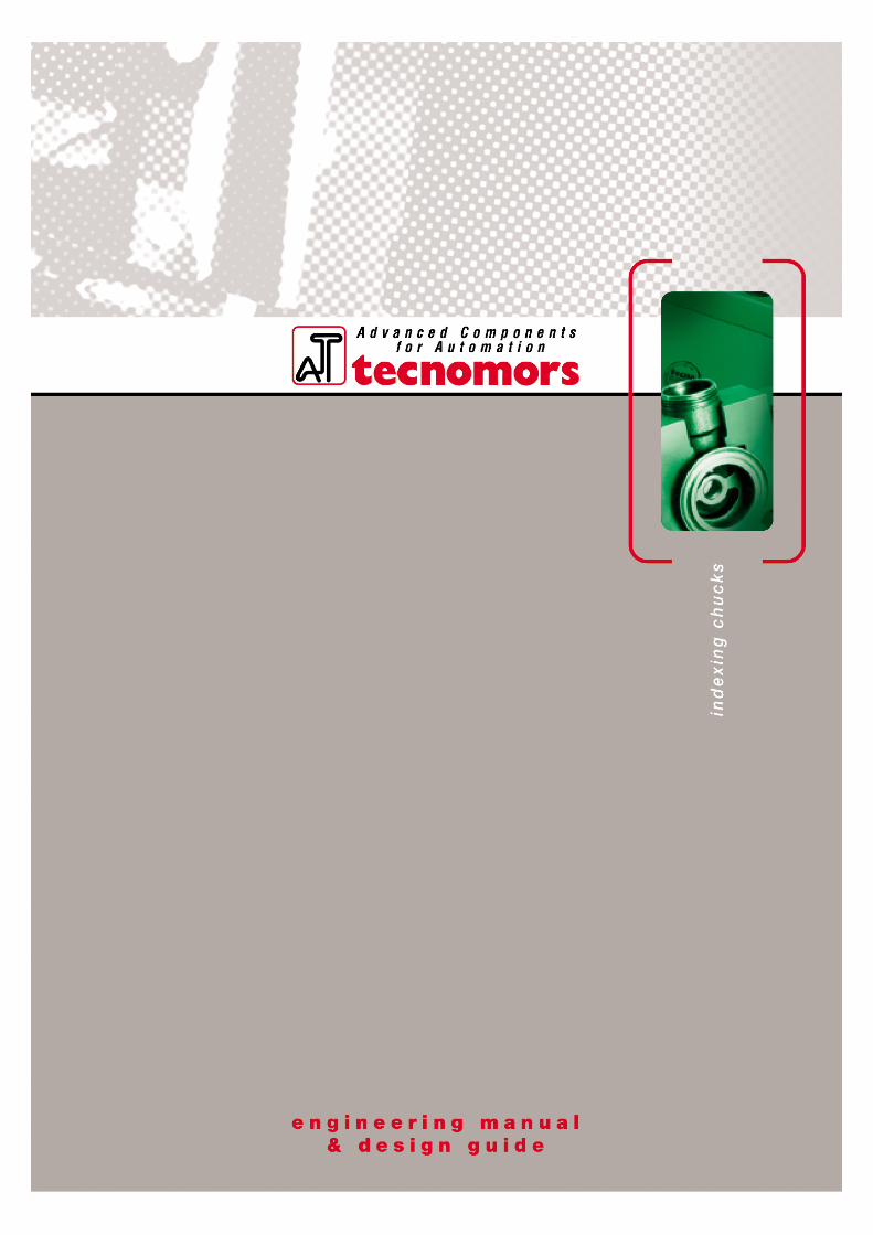
MD/MDEMD4x90° / MDE8x45°- Automatic indexing power chuck.Hydraulic feed.
MADVManual self-centering power chuck. Manual clamping and manual indexing.
MADTSemi-automatic self-centering power chuck. Draw rod clamping and manual indexing.
EQUIPMENTAdapter plate for machine spindle .
E.13 - E.32
E.35 - E.38
E.39 - E.42
E.43
Overview
E.11
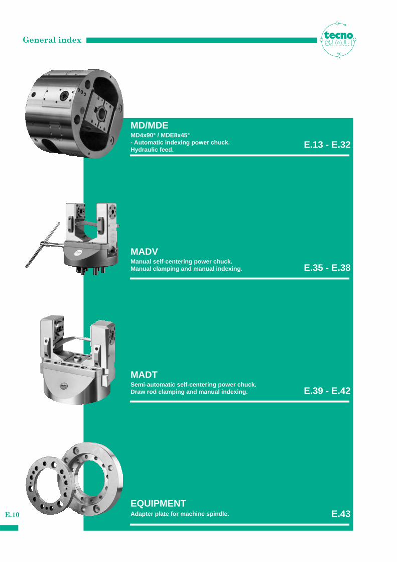
INDEXING CHUCKS
Mechanical indexing power chucks are used
by industries to work pieces with faces at rightand axial angles using single loading andblockage.
To work these profiles with traditional chucks
every side needs a new clamping and a repla-cement : this causes precision and time lost.
The complete working with indexing power
chucks is made with only a rotation clamping,during rotation and indexing processes theworkpiece is closed in the chuck.
w i th the automatic version it is happend
without stopping chuck on the lathe.
Initially conceived to work crosspieces and
valve bodies, over the last years constantimprovements have been made to their construction and quality; this has led to a vasterapplication in the automobile, aeronautical,industrial components and in all industrial sectors needing to work pieces with a crossedaxis in a single hold.
A utomatic and semi-automatic indexing
chucks are a good alternative to expencivespecial working machine or transfert machinewith rotary table.
Manual power chucks are the best solution to
work small series, prototype and equipment onlathe and on milling machines.
Very precise references and technical specifi-
cations adopted permit fast retooling of thepower chuck between jobs and fast mountingand dismounting on the machine.
With this catalog we would help our custo-
mers giving all the tecnical informations andspecifications they need about our indexingpower chucks production.
Special chucks can be designed and manufac-
tured on customer request.
ITALY
This photo shows some pieces which can be worked with indexing chucks
Selection of the chuck
E.12
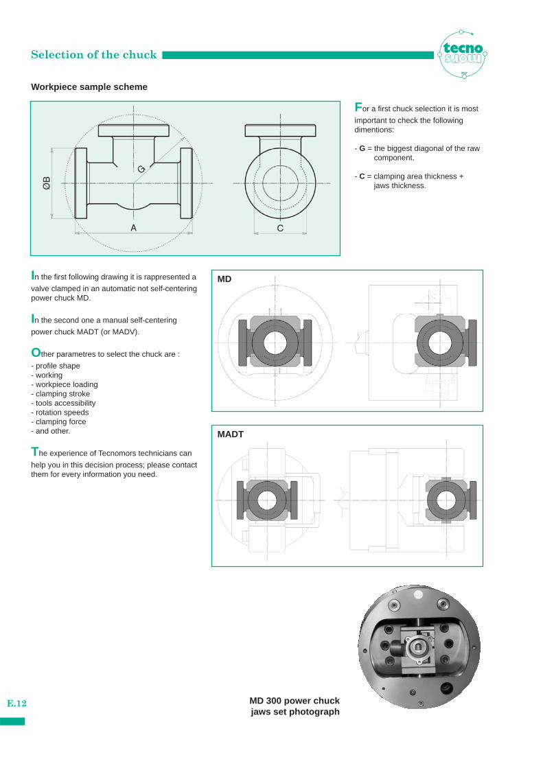
Workpiece sample scheme
ITALY
In the first following drawing it is rappresented a
valve clamped in an automatic not self-centeringpower chuck MD.
In the second one a manual self-centering
power chuck MADT (or MADV).
Other parametres to select the chuck are :
- profile shape- working- workpiece loading- clamping stroke- tools accessibility- rotation speeds- clamping force- and other.
The experience of Tecnomors technicians can
help you in this decision process; please contactthem for every information you need.
For a first chuck selection it is most
important to check the followingdimentions:
- G = the biggest diagonal of the raw component.
- C = clamping area thickness + jaws thickness.
MD
MADT
MD 300 power chuck jaws set photograph
MD/MDE • Features
E.13
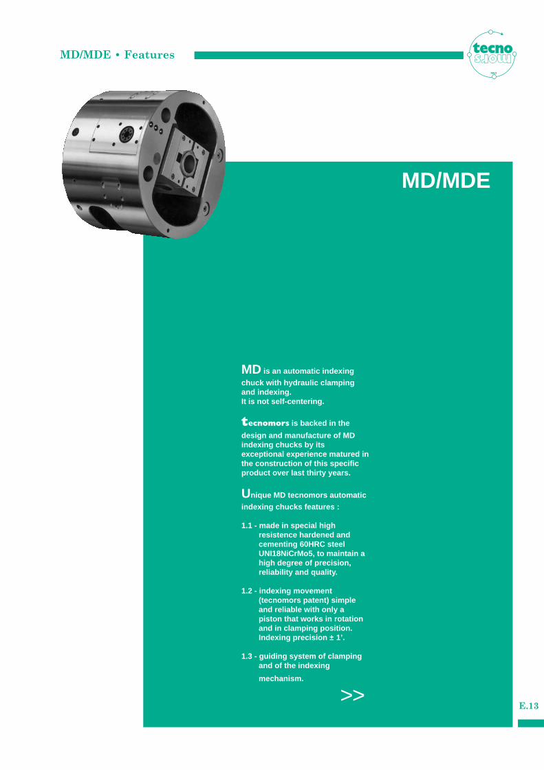
MD is an automatic indexing
chuck with hydraulic clampingand indexing. It is not self-centering.
tecnomors is backed in the
design and manufacture of MDindexing chucks by its exceptional experience matured inthe construction of this specificproduct over last thirty years.
Unique MD tecnomors automatic
indexing chucks features :
1.1 - made in special high resistence hardened and cementing 60HRC steel UNI18NiCrMo5, to maintain a high degree of precision, reliability and quality.
1.2 - indexing movement (tecnomors patent) simple and reliable with only a piston that works in rotation and in clamping position. Indexing precision ± 1’.
1.3 - guiding system of clamping and of the indexing
mechanism.
>>
ITALY
MD/MDE
MD/MDE • Features
E.14
ITALY
- This system uses 2 pre-loaded solid
straight roller radially and 1 axial bearing.
1.4 - seals against contamination by coolant,
chips or dust.
1.5 - constant and long lasting precision.
1.6 - easy installation to the machine.
1.7 - the chuck is connected to the rear
rotating oil manifold thanks to the nest tube. This tube system is supplied with grinding hardened steel clutchs.
1.8 - centrifugal force compensation system
for parts susceptible to deformations to obtain an higher productivity performance.
1.9 - indexing control device.
1.10 - a good automation system level grows
using robot to load and to unload workpieces.
tecnomors co-operates with
anthropomorphic and/or cartesian robot manufacturers also in grippers supply.
Other MD automatic indexing chuck technical
features:
2.1 - indexing process is possible also in
rotation position to allow a fast indexing position passage. The rotation speed has to be not at the maximum power.
2.2 - indexing takes, with position control,
approx. 2-4 seconds per 90°, depending on the size of the chuck.
2.3 - very simple hydraulic system
based on 2 indexing mechanism ports, 2 clamping pistons ports and 1 manifold drain.
2.4 - the chucking piston is
connected to a safety device and keeps the working securely gripped in the jaws even in the event of a complete pressure loss.
2.5 - costant and automatic
control of the indexing position and other working parametres by a separate electronic interface (not supplied) by the machine CNC.
2.6 - Optional:
• Retractable Locator see (pag. E.30)
2.7 - Complete “Operating Manual”
is supplied with the chuck.
2.8 - The MDE 8x45° chucks are supplied on
request.
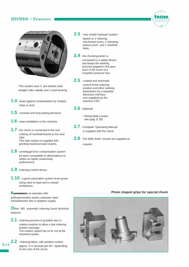
Photo shaped grips for special chuck
MD 4x90°• Indexing - Clamping system
E.15
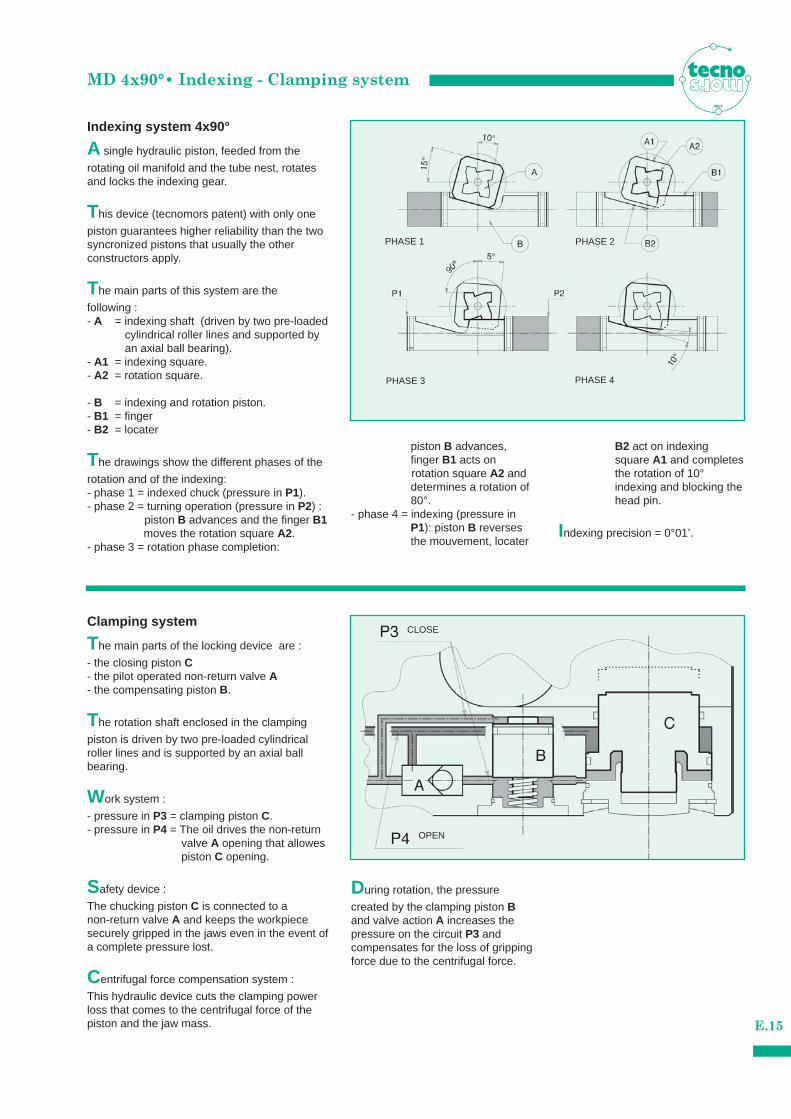
Indexing system 4x90°
Clamping system
A single hydraulic piston, feeded from the
rotating oil manifold and the tube nest, rotatesand locks the indexing gear.
This device (tecnomors patent) with only one
piston guarantees higher reliability than the twosyncronized pistons that usually the other constructors apply.
The main parts of this system are the
following :- A = indexing shaft (driven by two pre-loaded
cylindrical roller lines and supported by an axial ball bearing).
- A1 = indexing square.- A2 = rotation square.
- B = indexing and rotation piston.- B1 = finger- B2 = locater
The drawings show the different phases of the
rotation and of the indexing:- phase 1 = indexed chuck (pressure in P1).- phase 2 = turning operation (pressure in P2) :
piston B advances and the finger B1moves the rotation square A2.
- phase 3 = rotation phase completion:
The main parts of the locking device are :
- the closing piston C- the pilot operated non-return valve A- the compensating piston B.
The rotation shaft enclosed in the clamping
piston is driven by two pre-loaded cylindrical roller lines and is supported by an axial ball bearing.
Work system :
- pressure in P3 = clamping piston C.- pressure in P4 = The oil drives the non-return
valve A opening that allowes piston C opening.
Safety device :
The chucking piston C is connected to a non-return valve A and keeps the workpiecesecurely gripped in the jaws even in the event ofa complete pressure lost.
Centrifugal force compensation system :
This hydraulic device cuts the clamping powerloss that comes to the centrifugal force of thepiston and the jaw mass.
piston B advances, finger B1 acts on rotation square A2 and determines a rotation of 80°.
- phase 4 = indexing (pressure in P1): piston B reverses the mouvement, locater
During rotation, the pressure
created by the clamping piston Band valve action A increases thepressure on the circuit P3 and compensates for the loss of grippingforce due to the centrifugal force.
B2 act on indexing square A1 and completes the rotation of 10°indexing and blocking the head pin.
Indexing precision = 0°01’.
ITALY
PHASE 4PHASE 3
PHASE 2PHASE 1
CLOSE
OPEN
MD 4x90° • Technical specifications
E.16
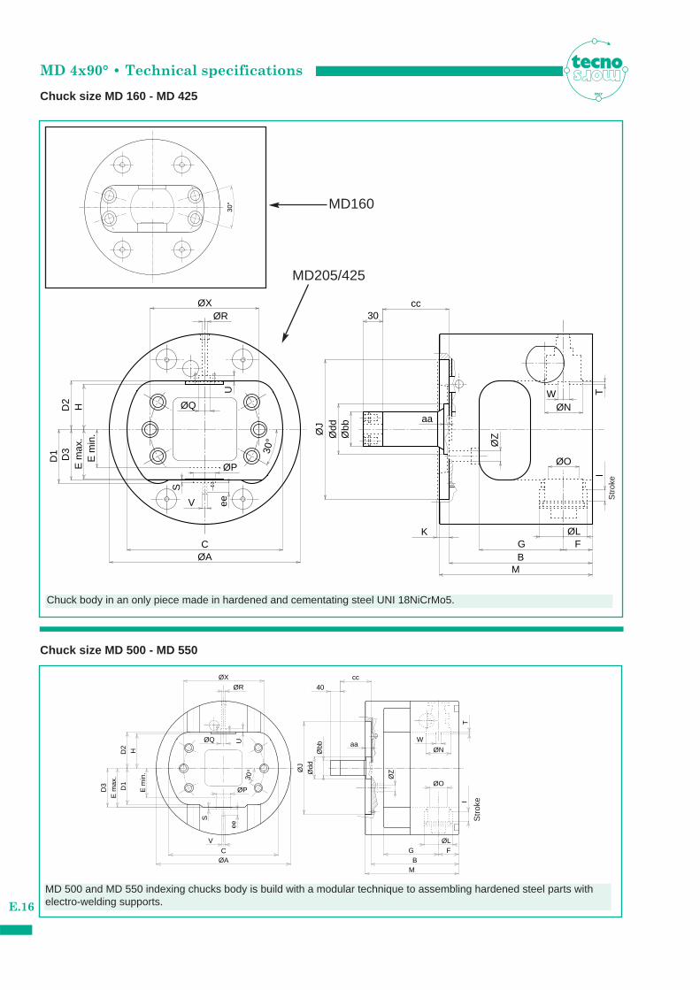
Chuck size MD 160 - MD 425
Chuck size MD 500 - MD 550
ITALY
aa
S
30°
eeVØ
Z
ØQ
D3
Ødd
ITW
B
ØLG F
M
ØN
ØOØP
ØR
D2
E m
in.
30
ØA
ccØX
C
D1
E m
ax.
H
ØJ
Øbb
K
U30
°
S
aa
30°
V
U
T
ØZ
ØO
I
ØN
W
BØAFGC
40
M
ØL
D3
E m
ax.
D1
E m
in.
D2 H
ØXØR
ØQ
ØP
ee
ØJ
Ødd
Øbb
cc
Chuck body in an only piece made in hardened and cementating steel UNI 18NiCrMo5.
MD 500 and MD 550 indexing chucks body is build with a modular technique to assembling hardened steel parts with electro-welding supports.
Str
oke
Str
oke
MD160
MD205/425
MD 4x90° • Technical specifications
E.17
ITALY
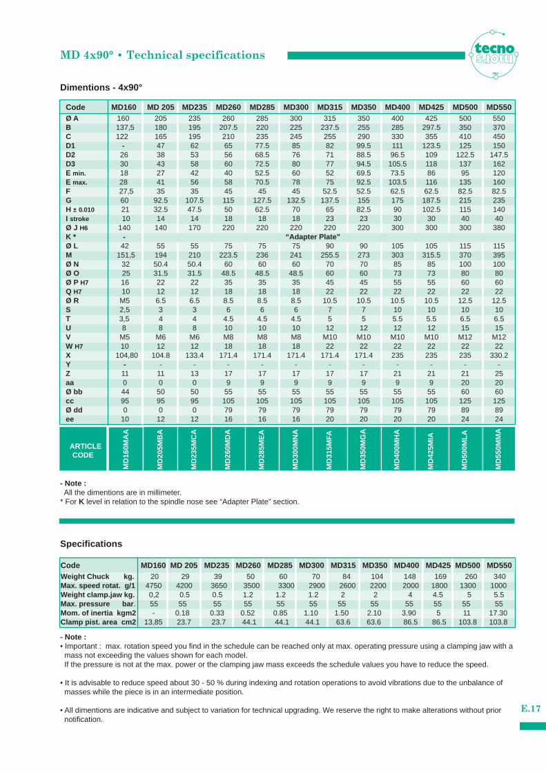
Dimentions - 4x90°
Specifications
- Note :• Important : max. rotation speed you find in the schedule can be reached only at max. operating pressure using a clamping jaw with a
mass not exceeding the values shown for each model.If the pressure is not at the max. power or the clamping jaw mass exceeds the schedule values you have to reduce the speed.
• It is advisable to reduce speed about 30 - 50 % during indexing and rotation operations to avoid vibrations due to the unbalance of masses while the piece is in an intermediate position.
• All dimentions are indicative and subject to variation for technical upgrading. We reserve the right to make alterations without prior notification.
- Note :All the dimentions are in millimeter.
* For K level in relation to the spindle nose see “Adapter Plate” section.
Code MD160 MD 205 MD235 MD260 MD285 MD300 MD315 MD350 MD400 MD425 MD500 MD550Ø A 160 205 235 260 285 300 315 350 400 425 500 550B 137,5 180 195 207.5 220 225 237.5 255 285 297.5 350 370C 122 165 195 210 235 245 255 290 330 355 410 450
G 60 92.5 107.5 115 127.5 132.5 137.5 155 175 187.5 215 235H ± 0.010 21 32.5 47.5 50 62.5 70 65 82.5 90 102.5 115 140I stroke 10 14 14 18 18 18 23 23 30 30 40 40Ø J H6 140 140 170 220 220 220 220 220 300 300 300 380
Ø L 42 55 55 75 75 75 90 90 105 105 115 115M 151,5 194 210 223.5 236 241 255.5 273 303 315.5 370 395Ø N 32 50.4 50.4 60 60 60 70 70 85 85 100 100Ø O 25 31.5 31.5 48.5 48.5 48.5 60 60 73 73 80 80Ø P H7 16 22 22 35 35 35 45 45 55 55 60 60Q H7 10 12 12 18 18 18 22 22 22 22 22 22Ø R M5 6.5 6.5 8.5 8.5 8.5 10.5 10.5 10.5 10.5 12.5 12.5S 2,5 3 3 6 6 6 7 7 10 10 10 10T 3,5 4 4 4.5 4.5 4.5 5 5 5.5 5.5 6.5 6.5U 8 8 8 10 10 10 12 12 12 12 15 15V M5 M6 M6 M8 M8 M8 M10 M10 M10 M10 M12 M12W H7 10 12 12 18 18 18 22 22 22 22 22 22X 104,80 104.8 133.4 171.4 171.4 171.4 171.4 171.4 235 235 235 330.2Y - - - - - - - - - - - -Z 11 11 13 17 17 17 17 17 21 21 21 25aa 0 0 0 9 9 9 9 9 9 9 20 20Ø bb 44 50 50 55 55 55 55 55 55 55 60 60cc 95 95 95 105 105 105 105 105 105 105 125 125Ø dd 0 0 0 79 79 79 79 79 79 79 89 89ee 10 12 12 16 16 16 20 20 20 20 24 24
D1 - 47 62 65 77.5 85 82 99.5 111 123.5 125 150D2 26 38 53 56 68.5 76 71 88.5 96.5 109 122.5 147.5D3 30 43 58 60 72.5 80 77 94.5 105.5 118 137 162E min. 18 27 42 40 52.5 60 52 69.5 73.5 86 95 120E max. 28 41 56 58 70.5 78 75 92.5 103.5 116 135 160F 27,5 35 35 45 45 45 52.5 52.5 62.5 62.5 82.5 82.5
K * - “Adapter Plate”
ARTICLECODE
MD
205M
BA
MD
160M
AA
MD
235M
CA
MD
260M
DA
MD
285M
EA
MD
300M
NA
MD
315M
FA
MD
350M
GA
MD
400M
HA
MD
425M
IA
MD
500M
LA
MD
550M
MA
Weight Chuck kg. 20 29 39 50 60 70 84 104 148 169 260 340Max. speed rotat. g/1 4750 4200 3650 3500 3300 2900 2600 2200 2000 1800 1300 1000Weight clamp.jaw kg. 0,2 0.5 0.5 1.2 1.2 1.2 2 2 4 4.5 5 5.5
Mom. of inertia kgm2 - 0.18 0.33 0.52 0.85 1.10 1.50 2.10 3.90 5 11 17.30Clamp pist. area cm2 13,85 23.7 23.7 44.1 44.1 44.1 63.6 63.6 86.5 86.5 103.8 103.8
Max. pressure bar . 55 55 55 55 55 55 55 55 55 55 55 55
Code MD160 MD 205 MD235 MD260 MD285 MD300 MD315 MD350 MD400 MD425 MD500 MD550
MD 4x90° • Rear rotating oil manifold
E.18
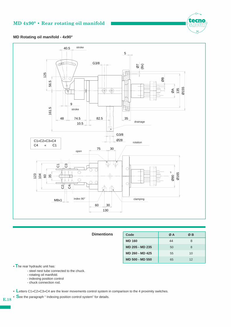
MD Rotating oil manifold - 4x90°
ITALY
35
5
82.5
ØA
9
Ø15
5
Ø90
h7
G3/8
M8x1
C1
C2
C3
C4
C1»C2»C3»C4C4 « C1
ØB
Ø28Ø
7(8
x)
Ø16
5
3060
130
G3/8
74.5
40.556
.516
1.5
125
60
10.5
104
48
135
30
123
75
35
Dimentions
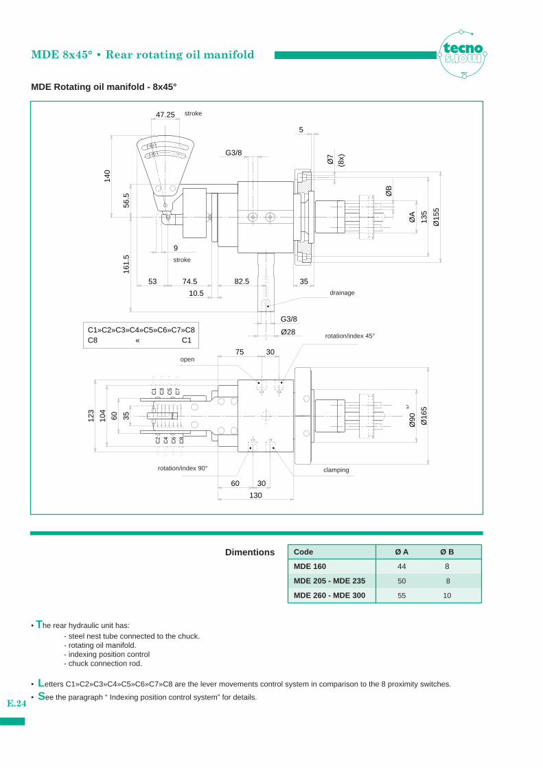
• The rear hydraulic unit has:- steel nest tube connected to the chuck.- rotating oil manifold.- indexing position control - chuck connection rod.
• Letters C1»C2»C3»C4 are the lever movements control system in comparison to the 4 proximity switches.
• See the paragraph “ Indexing position control system” for details.
Code Ø A Ø B
MD 160 44 8
MD 205 - MD 235 50 8
MD 500 - MD 550 65 12
MD 260 - MD 425 55 10
index 90°
rotation
open
drainage
stroke
stroke
clamping
MD 4x90° • Indexing position control system
E.19
C1
C4
C2
C3
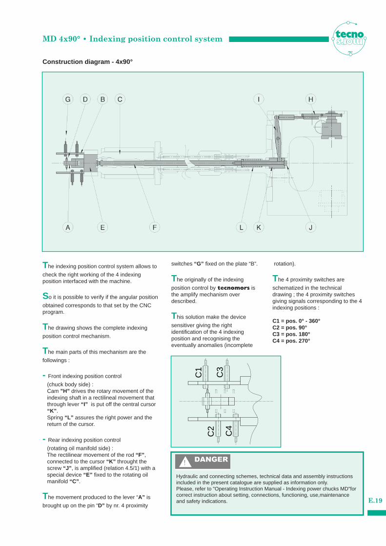
Construction diagram - 4x90°
The indexing position control system allows to
check the right working of the 4 indexing position interfaced with the machine.
So it is possible to verify if the angular position
obtained corresponds to that set by the CNCprogram.
The drawing shows the complete indexing
position control mechanism.
The main parts of this mechanism are the
followings :
- Front indexing position control
(chuck body side) :Cam ”H” drives the rotary movement of the indexing shaft in a rectilineal movement that through lever “I” is put off the central cursor “K” . Spring “L” assures the right power and the return of the cursor.
- Rear indexing position control
(rotating oil manifold side) :The rectilinear movement of the rod “F” , connected to the cursor “K” throught the screw “J” , is amplified (relation 4.5/1) with a special device “E” fixed to the rotating oil manifold “C” .
The movement produced to the lever “A” is
brought up on the pin “D” by nr. 4 proximity
switches “G” fixed on the plate “B”.
The originally of the indexing
position control by tecnomors isthe amplify mechanism over described.
This solution make the device
sensitiver giving the right identification of the 4 indexing position and recognising the eventually anomalies (incomplete
rotation).
The 4 proximity switches are
schematized in the technical drawing ; the 4 proximity switchesgiving signals corresponding to the 4indexing positions :
C1 = pos. 0° - 360°C2 = pos. 90°C3 = pos. 180°C4 = pos. 270°
ITALY
Hydraulic and connecting schemes, technical data and assembly instructionsincluded in the present catalogue are supplied as information only.Please, refer to "Operating Instruction Manual - Indexing power chucks MD"forcorrect instruction about setting, connections, functioning, use,maintenance and safety indications.
�60 bar
10 - 55 bar
60 - 100 lt.
55 bar
0.7÷
1 lt
20 b
ar
M
10 µm
16 lt/min
125 µm
2.5 Kw
MD 4x90° • Hydraulic system
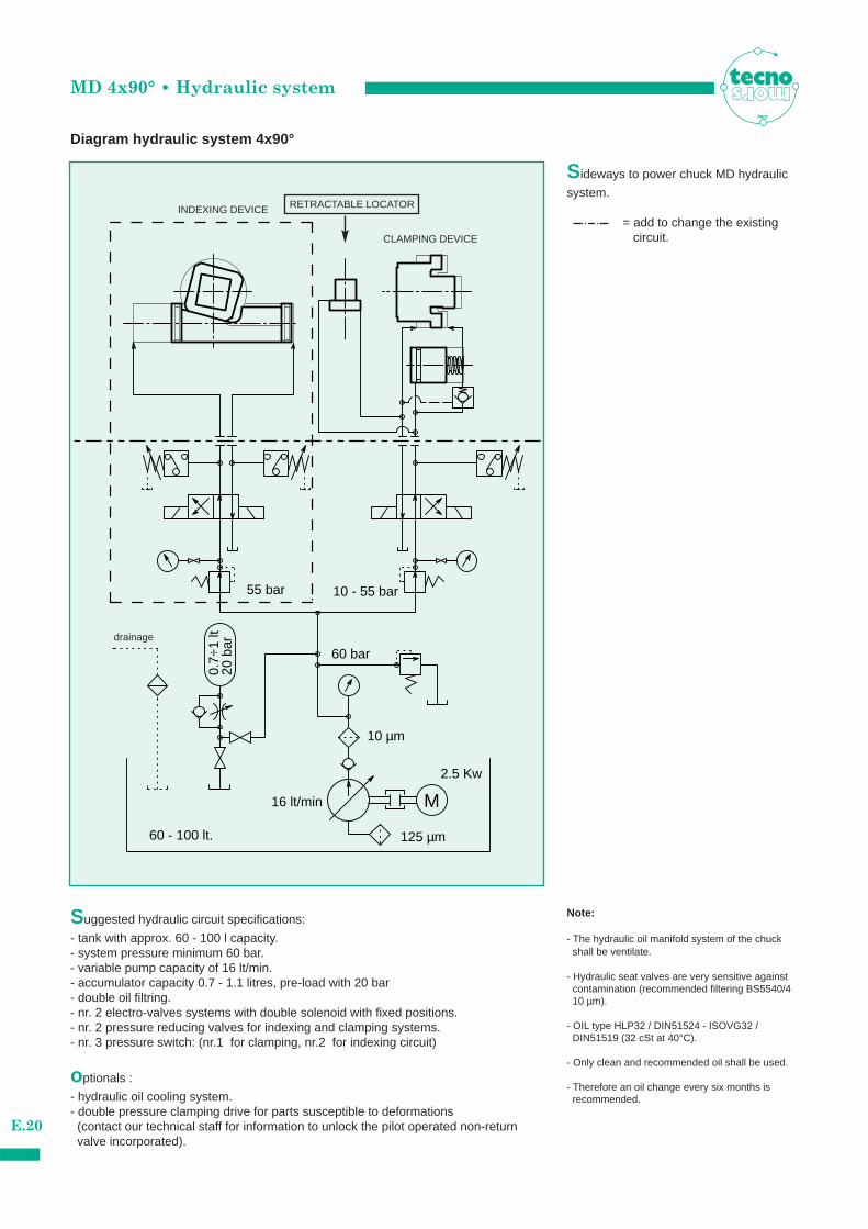
Diagram hydraulic system 4x90°
ITALY
Suggested hydraulic circuit specifications:
- tank with approx. 60 - 100 l capacity.- system pressure minimum 60 bar.- variable pump capacity of 16 lt/min.- accumulator capacity 0.7 - 1.1 litres, pre-load with 20 bar- double oil filtring.- nr. 2 electro-valves systems with double solenoid with fixed positions.- nr. 2 pressure reducing valves for indexing and clamping systems.- nr. 3 pressure switch: (nr.1 for clamping, nr.2 for indexing circuit)
optionals :
- hydraulic oil cooling system.- double pressure clamping drive for parts susceptible to deformations
(contact our technical staff for information to unlock the pilot operated non-return valve incorporated).
Sideways to power chuck MD hydraulic
system.
= add to change the existing circuit.
Note:
- The hydraulic oil manifold system of the chuck shall be ventilate.
- Hydraulic seat valves are very sensitive against contamination (recommended filtering BS5540/4 10 µm).
- OIL type HLP32 / DIN51524 - ISOVG32 / DIN51519 (32 cSt at 40°C).
- Only clean and recommended oil shall be used.
- Therefore an oil change every six months is recommended.
E.20
INDEXING DEVICE
CLAMPING DEVICE
RETRACTABLE LOCATOR
drainage
MDE 8x45° • Indexing - Clamping system
E.21
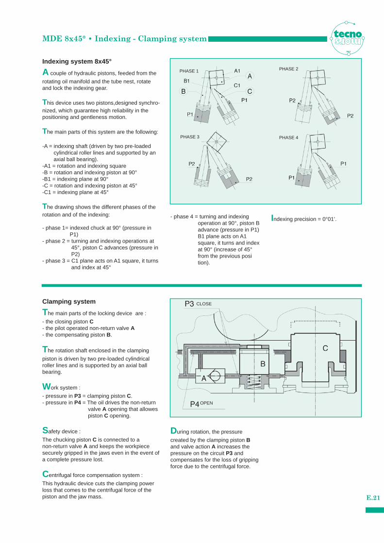
Indexing system 8x45°
Clamping system
A couple of hydraulic pistons, feeded from the
rotating oil manifold and the tube nest, rotateand lock the indexing gear.
This device uses two pistons,designed synchro-nized, which guarantee high reliability in thepositioning and gentleness motion.
The main parts of this system are the following:
-A = indexing shaft (driven by two pre-loaded cylindrical roller lines and supported by an axial ball bearing).
-A1 = rotation and indexing square-B = rotation and indexing piston at 90°-B1 = indexing plane at 90°-C = rotation and indexing piston at 45°-C1 = indexing plane at 45°
The drawing shows the different phases of therotation and of the indexing:
- phase 1= indexed chuck at 90° (pressure in P1)
- phase 2 = turning and indexing operations at 45°, piston C advances (pressure in P2)
- phase 3 = C1 plane acts on A1 square, it turns and index at 45°
The main parts of the locking device are :
- the closing piston C- the pilot operated non-return valve A- the compensating piston B.
The rotation shaft enclosed in the clamping
piston is driven by two pre-loaded cylindrical roller lines and is supported by an axial ball bearing.
Work system :
- pressure in P3 = clamping piston C.- pressure in P4 = The oil drives the non-return
valve A opening that allowes piston C opening.
Safety device :
The chucking piston C is connected to a non-return valve A and keeps the workpiecesecurely gripped in the jaws even in the event ofa complete pressure lost.
Centrifugal force compensation system :
This hydraulic device cuts the clamping powerloss that comes to the centrifugal force of thepiston and the jaw mass.
- phase 4 = turning and indexingoperation at 90°, piston Badvance (pressure in P1)B1 plane acts on A1 square, it turns and indexat 90° (increase of 45°from the previous position).
During rotation, the pressure
created by the clamping piston Band valve action A increases thepressure on the circuit P3 and compensates for the loss of grippingforce due to the centrifugal force.
Indexing precision = 0°01’.
ITALY
PHASE 1 PHASE 2
PHASE 3 PHASE 4
OPEN
CLOSE
MDE 8x45° • Technical specifications
E.22
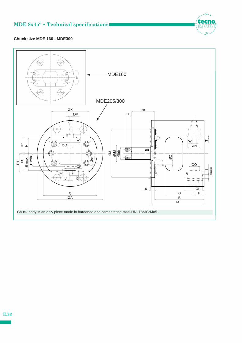
Chuck size MDE 160 - MDE300
ITALY
aa
S
30°
eeV
ØZ
ØQ
D3
Ødd
ITW
B
ØLG F
M
ØN
ØOØP
ØR
D2
E m
in.
30
ØA
ccØX
C
D1
E m
ax.
H
ØJ
Øbb
K
U30
°
Chuck body in an only piece made in hardened and cementating steel UNI 18NiCrMo5.st
roke
MDE160
MDE205/300
MDE 8x45° • Technical specifications
E.23
ITALY
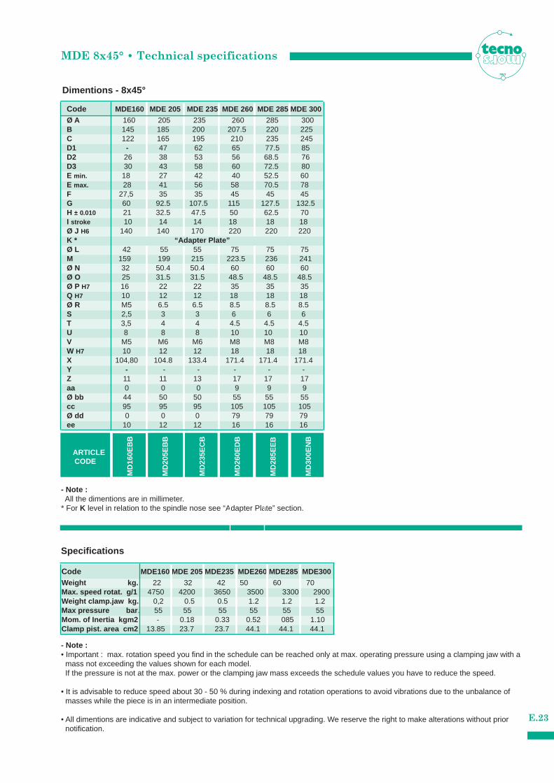
Specifications
- Note :All the dimentions are in millimeter.
* For K level in relation to the spindle nose see “Adapter Plate” section.
Code MDE160 MDE 205 MDE 235 MDE 260 MDE 285 MDE 300
Ø A 160 205 235 260 285 300B 145 185 200 207.5 220 225C 122 165 195 210 235 245
G 60 92.5 107.5 115 127.5 132.5H ± 0.010 21 32.5 47.5 50 62.5 70I stroke 10 14 14 18 18 18Ø J H6 140 140 170 220 220 220
Ø L 42 55 55 75 75 75M 159 199 215 223.5 236 241Ø N 32 50.4 50.4 60 60 60Ø O 25 31.5 31.5 48.5 48.5 48.5Ø P H7 16 22 22 35 35 35Q H7 10 12 12 18 18 18Ø R M5 6.5 6.5 8.5 8.5 8.5S 2,5 3 3 6 6 6T 3,5 4 4 4.5 4.5 4.5U 8 8 8 10 10 10V M5 M6 M6 M8 M8 M8W H7 10 12 12 18 18 18X 104,80 104.8 133.4 171.4 171.4 171.4Y - - - - - -Z 11 11 13 17 17 17aa 0 0 0 9 9 9Ø bb 44 50 50 55 55 55cc 95 95 95 105 105 105Ø dd 0 0 0 79 79 79ee 10 12 12 16 16 16
D1 - 47 62 65 77.5 85D2 26 38 53 56 68.5 76D3 30 43 58 60 72.5 80E min. 18 27 42 40 52.5 60E max. 28 41 56 58 70.5 78F 27,5 35 35 45 45 45
ARTICLECODE
MD
205E
BB
MD
160E
BB
MD
235E
CB
MD
260E
DB
MD
285E
EB
MD
300E
NB
K * “Adapter Plate”
Weight kg. 22 32 42 50 60 70 Max. speed rotat. g/1 4750 4200 3650 3500 3300 2900Weight clamp.jaw kg. 0,2 0.5 0.5 1.2 1.2 1.2
Mom. of Inertia kgm2 - 0.18 0.33 0.52 085 1.10 Clamp pist. area cm2 13.85 23.7 23.7 44.1 44.1 44.1
Max pressure bar . 55 55 55 55 55 55
Code MDE160 MDE 205 MDE235 MDE260 MDE285 MDE300
- Note :• Important : max. rotation speed you find in the schedule can be reached only at max. operating pressure using a clamping jaw with a
mass not exceeding the values shown for each model.If the pressure is not at the max. power or the clamping jaw mass exceeds the schedule values you have to reduce the speed.
• It is advisable to reduce speed about 30 - 50 % during indexing and rotation operations to avoid vibrations due to the unbalance of masses while the piece is in an intermediate position.
• All dimentions are indicative and subject to variation for technical upgrading. We reserve the right to make alterations without prior notification.
Dimentions - 8x45°
MDE 8x45° • Rear rotating oil manifold
E.24
MDE Rotating oil manifold - 8x45°
ITALY
C1
35
5
82.5
ØA
9
Ø15
5
Ø90
h7
G3/8C1»C2»C3»C4»C5»C6»C7»C8C8 « C1
C3
C7
C2
C6
C4
C8
C5
ØB
Ø28Ø
7(8
x)
Ø16
5
53
140
47.25
3060
130
G3/8
74.5
56.5
161.
5
60
10.5
104
135
30
123
75
35
Dimentions
• The rear hydraulic unit has:- steel nest tube connected to the chuck.- rotating oil manifold.- indexing position control - chuck connection rod.
• Letters C1»C2»C3»C4»C5»C6»C7»C8 are the lever movements control system in comparison to the 8 proximity switches.
• See the paragraph “ Indexing position control system” for details.
Code Ø A Ø B
MDE 160 44 8
MDE 205 - MDE 235 50 8
MDE 260 - MDE 300 55 10
stroke
drainage
rotation/index 45°
open
clampingrotation/index 90°
stroke
MDE 8x45° • Indexing position control system
E.25
C2
C4
C6
C8
C1 C3 C5 C7
C2 C4 C6 C8
C1
C3
C7
C5
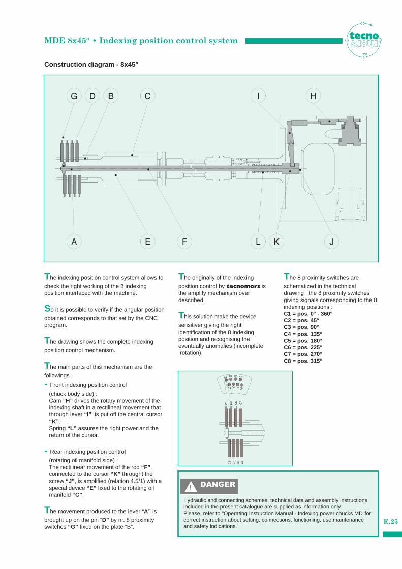
Construction diagram - 8x45°
The indexing position control system allows to
check the right working of the 8 indexing position interfaced with the machine.
So it is possible to verify if the angular position
obtained corresponds to that set by the CNCprogram.
The drawing shows the complete indexing
position control mechanism.
The main parts of this mechanism are the
followings :
- Front indexing position control
(chuck body side) :Cam ”H” drives the rotary movement of the indexing shaft in a rectilineal movement that through lever “I” is put off the central cursor “K” . Spring “L” assures the right power and the return of the cursor.
- Rear indexing position control
(rotating oil manifold side) :The rectilinear movement of the rod “F” , connected to the cursor “K” throught the screw “J” , is amplified (relation 4.5/1) with a special device “E” fixed to the rotating oil manifold “C” .
The movement produced to the lever “A” is
brought up on the pin “D” by nr. 8 proximityswitches “G” fixed on the plate “B”.
The originally of the indexing
position control by tecnomors isthe amplify mechanism over described.
This solution make the device
sensitiver giving the right identification of the 8 indexing position and recognising the eventually anomalies (incompleterotation).
The 8 proximity switches are
schematized in the technical drawing ; the 8 proximity switchesgiving signals corresponding to the 8indexing positions :C1 = pos. 0° - 360°C2 = pos. 45°C3 = pos. 90°C4 = pos. 135°C5 = pos. 180°C6 = pos. 225°C7 = pos. 270°C8 = pos. 315°
ITALY
Hydraulic and connecting schemes, technical data and assembly instructionsincluded in the present catalogue are supplied as information only.Please, refer to "Operating Instruction Manual - Indexing power chucks MD"forcorrect instruction about setting, connections, functioning, use,maintenance and safety indications.
MDE 8x45° • Hydraulic system
E.26
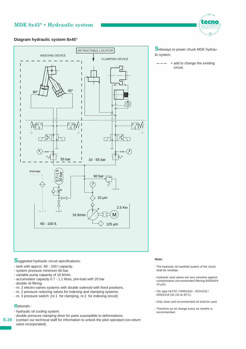
Diagram hydraulic system 8x45°
ITALY
M
0.7÷
1 lt
20 b
ar
60 bar
10 µm
16 lt/min
125 µm
2.5 Kw
60 - 100 lt.
55 bar 10 - 55 bar
90° 45°
Suggested hydraulic circuit specifications:
- tank with approx. 60 - 100 l capacity.- system pressure minimum 60 bar.- variable pump capacity of 16 lt/min.- accumulator capacity 0.7 - 1.1 litres, pre-load with 20 bar- double oil filtring.- nr. 2 electro-valves systems with double solenoid with fixed positions.- nr. 2 pressure reducing valves for indexing and clamping systems.- nr. 3 pressure switch: (nr.1 for clamping, nr.2 for indexing circuit)
optionals :
- hydraulic oil cooling system.- double pressure clamping drive for parts susceptible to deformations
(contact our technical staff for information to unlock the pilot operated non-return valve incorporated).
Sideways to power chuck MDE hydrau-
lic system.
= add to change the existing circuit.
Note:
- The hydraulic oil manifold system of the chuck shall be ventilate.
- Hydraulic seat valves are very sensitive against contamination (recommended filtering BS5540/4 10 µm).
- OIL type HLP32 / DIN51524 - ISOVG32 / DIN51519 (32 cSt at 40°C).
- Only clean and recommended oil shall be used.
- Therefore an oil change every six months is recommended.
INDEXING DEVICECLAMPING DEVICE
RETRACTABLE LOCATOR
drainage
MD/MDE • General connecting supply
E.27
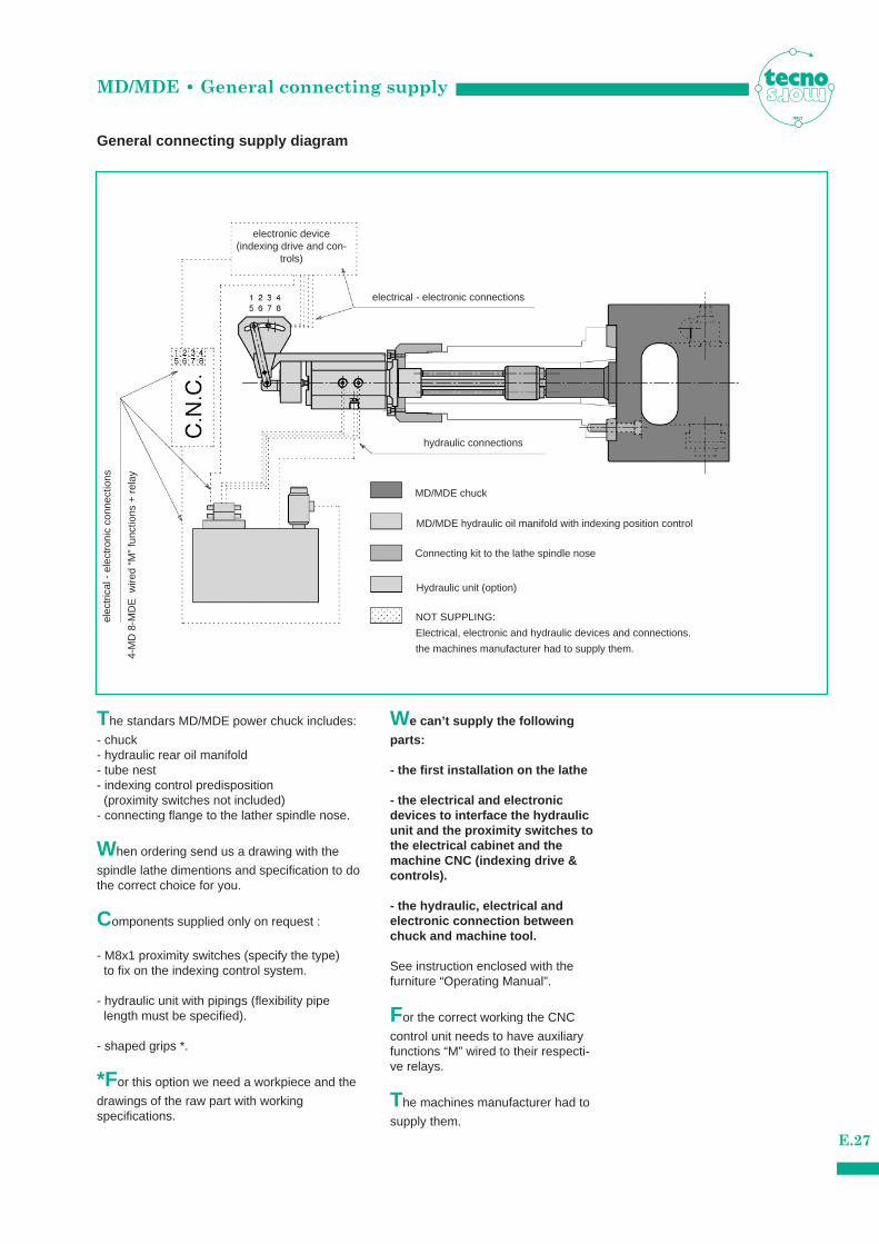
General connecting supply diagram
The standars MD/MDE power chuck includes:
- chuck- hydraulic rear oil manifold - tube nest - indexing control predisposition
(proximity switches not included)- connecting flange to the lather spindle nose.
When ordering send us a drawing with the
spindle lathe dimentions and specification to dothe correct choice for you.
Components supplied only on request :
- M8x1 proximity switches (specify the type) to fix on the indexing control system.
- hydraulic unit with pipings (flexibility pipe length must be specified).
- shaped grips *.
*For this option we need a workpiece and the
drawings of the raw part with working specifications.
We can’t supply the following
parts:
- the first installation on the lathe
- the electrical and electronic devices to interface the hydraulicunit and the proximity switches tothe electrical cabinet and themachine CNC (indexing drive &controls).
- the hydraulic, electrical and electronic connection betweenchuck and machine tool.
See instruction enclosed with the furniture “Operating Manual”.
For the correct working the CNC
control unit needs to have auxiliaryfunctions “M” wired to their respecti-ve relays.
The machines manufacturer had to
supply them.
ITALY
electrical - electronic connections
hydraulic connections
MD/MDE chuck
MD/MDE hydraulic oil manifold with indexing position control
Connecting kit to the lathe spindle nose
Hydraulic unit (option)
NOT SUPPLING:
Electrical, electronic and hydraulic devices and connections.
the machines manufacturer had to supply them.
elec
tric
al -
ele
ctro
nic
conn
ectio
ns
4-M
D 8
-MD
E w
ired
“M”
func
tions
+ r
elay
electronic device(indexing drive and con-
trols)
MD/MDE • Mounting instructions
Mounting diagram
ITALY
W
V
U
R
Q
P
O
N
I
K
H
F
J
D1
C
A1
L
X
T
S
M
G
D2
G1
E
A2
B
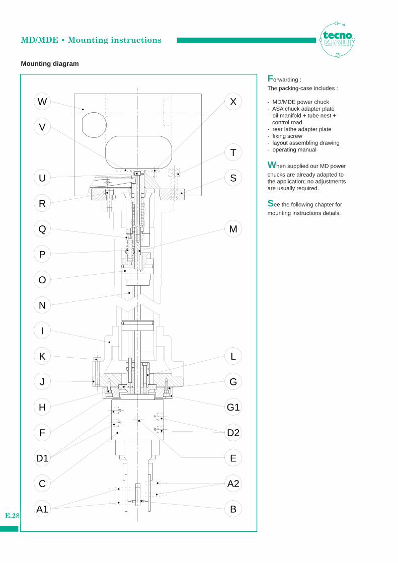
Forwarding :
The packing-case includes :
- MD/MDE power chuck- ASA chuck adapter plate- oil manifold + tube nest +
control road- rear lathe adapter plate- fixing screw- layout assembling drawing- operating manual
When supplied our MD power
chucks are already adapted tothe application; no adjustmentsare usually required.
See the following chapter for
mounting instructions details.
E.28
MD/MDE • Mounting instructions
E.29
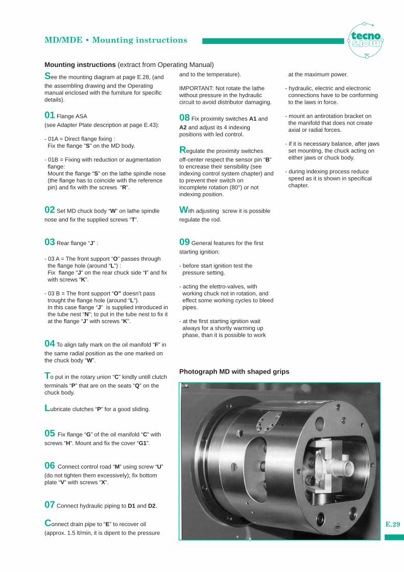
Mounting instructions (extract from Operating Manual)
See the mounting diagram at page E.28, (and
the assembling drawing and the Operatingmanual enclosed with the furniture for specificdetails).
01 Flange ASA
(see Adapter Plate description at page E.43):
- 01A = Direct flange fixing :Fix the flange ”S” on the MD body.
- 01B = Fixing with reduction or augmentation flange:Mount the flange “S” on the lathe spindle nose (the flange has to coincide with the reference pin) and fix with the screws “R”.
02 Set MD chuck body “W” on lathe spindle
nose and fix the supplied screws “T”.
03 Rear flange “J” :
- 03 A = The front support “O” passes through the flange hole (around “L”) :Fix flange “J” on the rear chuck side “I” and fix with screws “K”.
- 03 B = The front support “O” doesn’t pass trought the flange hole (around “L”).In this case flange “J” is supplied introduced in the tube nest “N”; to put in the tube nest to fix it at the flange “J” with screws “K”.
04 To align tally mark on the oil manifold “F” in
the same radial position as the one marked onthe chuck body “W”.
To put in the rotary union “C” kindly untill clutch
terminals “P” that are on the seats “Q” on thechuck body.
Lubricate clutches “P” for a good sliding.
05 Fix flange “G” of the oil manifold “C” with
screws “H”. Mount and fix the cover “G1”.
06 Connect control road “M” using screw “U”
(do not tighten them excessively); fix bottomplate “V” with screws “X”.
07 Connect hydraulic piping to D1 and D2.
Connect drain pipe to “E” to recover oil
(approx. 1.5 lt/min, it is dipent to the pressure
and to the temperature).
IMPORTANT: Not rotate the lathewithout pressure in the hydraulic circuit to avoid distributor damaging.
08 Fix proximity switches A1 and
A2 and adjust its 4 indexing positions with led control.
Regulate the proximity switches
off-center respect the sensor pin “B”to encrease their sensibility (seeindexing control system chapter) andto prevent their switch onincomplete rotation (80°) or notindexing position.
With adjusting screw it is possible
regulate the rod.
09 General features for the first
starting ignition:
- before start ignition test the pressure setting.
- acting the elettro-valves, with working chuck not in rotation, and effect some working cycles to bleed pipes.
- at the first starting ignition wait always for a shortly warming up phase, than it is possible to work
at the maximum power.
- hydraulic, electric and electronic connections have to be conforming to the laws in force.
- mount an antirotation bracket on the manifold that does not create axial or radial forces.
- if it is necessary balance, after jaws set mounting, the chuck acting on either jaws or chuck body.
- during indexing process reduce speed as it is shown in specifical chapter.
ITALY
Photograph MD with shaped grips
MD/MDE Retractable LocatorITALY
Down
Close Open
Up
B CA
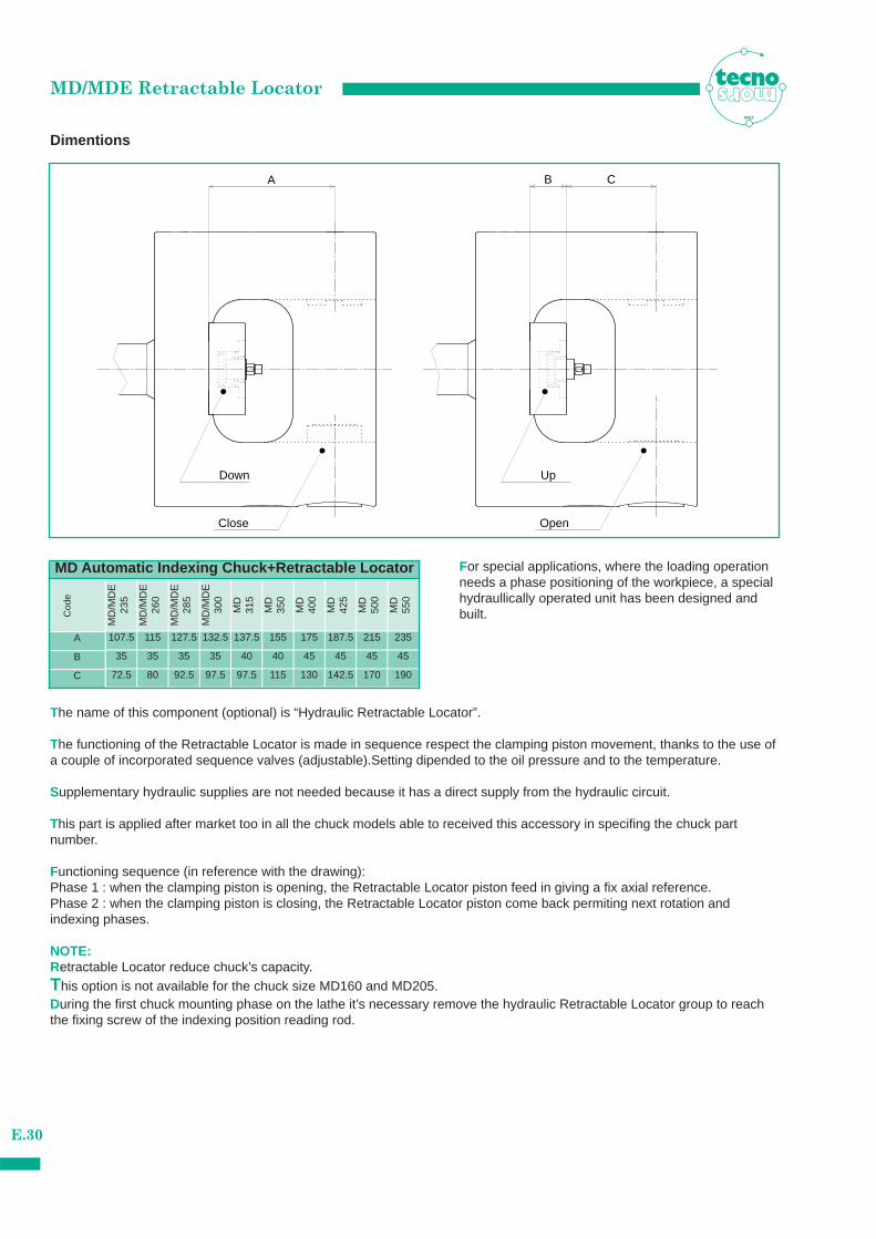
For special applications, where the loading operationneeds a phase positioning of the workpiece, a specialhydraullically operated unit has been designed andbuilt.
The name of this component (optional) is “Hydraulic Retractable Locator”.
The functioning of the Retractable Locator is made in sequence respect the clamping piston movement, thanks to the use ofa couple of incorporated sequence valves (adjustable).Setting dipended to the oil pressure and to the temperature.
Supplementary hydraulic supplies are not needed because it has a direct supply from the hydraulic circuit.
This part is applied after market too in all the chuck models able to received this accessory in specifing the chuck part number.
Functioning sequence (in reference with the drawing):Phase 1 : when the clamping piston is opening, the Retractable Locator piston feed in giving a fix axial reference.Phase 2 : when the clamping piston is closing, the Retractable Locator piston come back permiting next rotation andindexing phases.
NOTE:Retractable Locator reduce chuck’s capacity.This option is not available for the chuck size MD160 and MD205.During the first chuck mounting phase on the lathe it’s necessary remove the hydraulic Retractable Locator group to reachthe fixing screw of the indexing position reading rod.
Dimentions
E.30
MD Automatic Indexing Chuck+Retractable Locator
107.5 115 127.5 132.5 137.5 155A
Cod
e
MD
/MD
E23
5
MD
/MD
E26
0
MD
/MD
E28
5
MD
/MD
E30
0
MD
315
MD
350
175
MD
400
187.5
MD
425
215
MD
500
235
35 35 35 35 40 40B 45 45 45 45
72.5 80 92.5 97.5 97.5 115C 130 142.5 170 190
MD
550
E.31
MD
/MD
E26
0
MD
/MD
E23
5
D
J E
H
ØF
ØG
I
L
K
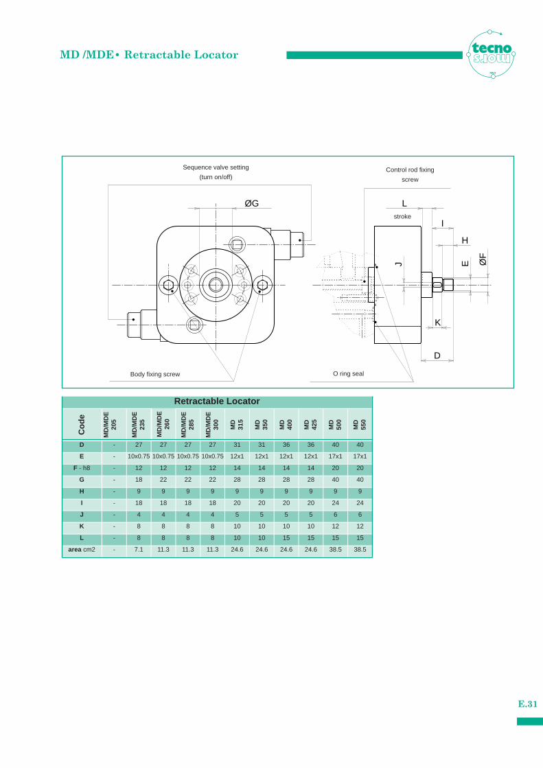
- 27 27 27 27 31 31D
Cod
e
MD
/MD
E20
5
MD
/MD
E28
5
MD
/MD
E30
0
MD
315
MD
350
36
MD
400
36
MD
425
40
MD
500
40
- 10x0.75 10x0.75 10x0.75 10x0.75 12x1 12x1E 12x1 12x1 17x1 17x1
- 12 12 12 12 14 14F - h8 14 14 20 20
- 18 22 22 22 28 28G 28 28 40 40
- 9 9 9 9 9 9H 9 9 9 9
- 18 18 18 18 20 20I 20 20 24 24
- 4 4 4 4 5 5J 5 5 6 6
- 8 8 8 8 10 10K 10 10 12 12
- 8 8 8 8 10 10L 15 15 15 15
- 7.1 11.3 11.3 11.3 24.6 24.6area cm2 24.6 24.6 38.5 38.5
MD
550
Body fixing screw O ring seal
Sequence valve setting
(turn on/off)Control rod fixing
screw
Retractable Locator
MD /MDE• Retractable LocatorITALY
stroke

NotesITALY
E.32
MADV - MADT • Features
E.33
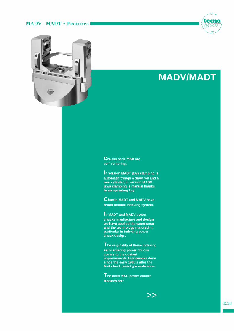
Chucks serie MAD are self-centering.
In version MADT jaws clamping is
automatic trough a draw rod and arear cylinder, in version MADVjaws clamping is manual thanksto an operating key.
Chucks MADT and MADV have
booth manual indexing system.
In MADT and MADV power
chucks manifacture and designwe have applied the experienceand the technology matured inparticular in indexing powerchuck design.
The originality of these indexing
self-centering power chuckscomes to the costant improvements tecnomors donesince the early 1960’s after thefirst chuck prototype realisation.
The main MAD power chucks
features are:
>>
ITALY
MADV/MADT
MADV - MADT • Features
E.34
ITALY
1.1 - made in special high resistence
hardened and cementing 60HRC steel UNI18NiCrMo5, to maintain a high degree of precision, reliability and quality.
1.2 - jaws slideways execution with gib allows
a good sliding surface finish with possibility to recover clearances consequent to wear.
1.3 - indexing movement simple and reliable:
a conical shutter guarantees the mechanical indexing. Indexing precision ±1’30” .
1.4 - shaft guide system with two lines of big
filled cylindrical pre-loaded roller radially and with a strong axial ball bearing axially.
1.5 - seals against contamination by coolant,
chips and dust.
1.6 - constant and long lasting precision.
1.7 - easy installation to the machine.
1.8 - standard with 4 indexing 90°
+ 1 indexing 45°.
On request special indexing positions
available (8x45°, 6x60°).
2.1 - MADT specifications :
- self-centering clamping.- big clamping capacity.- versions with long jaw for workpieces
that need a big radius of revolution.- quick and easy installation to the
machine, it is request only the connection to the hydraulic cylinder on the lathe.
2.2 - MADT benefits:
- manufacturing of different pieces and also of small series.
- workpieces with big radius of revolution and flanges with big diameter.
- could be apply in the same machine with a conventional 3 jaws power chuck thanks to the quick retooling increasing unit flexibility and productivity.
- the indexing device allowing a quick change between the multiple workingaxes.
- good tools accessibility thanks to the chuck shape.
2.3 - a special tecnomors device
with titled plane transmits the clamping force to the jaws.
2.4 - Chuck is supplied without
driving cylinder. See the specific chapter to check cylinder and chuck size.
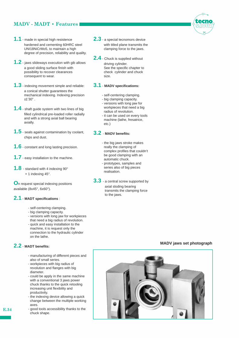
3.1 - MADV specifications:
- self-centering clamping.- big clamping capacity.- versions with long jaw for
workpieces that need a big radius of revolution.
- it can be used on every tools machine (lathe, fresatrice, etc.)
3.2 - MADV benefits:
- the big jaws stroke makes really the clamping of complex profiles that couldn’t be good clamping with an automatic chuck.
- prototypes, samples and series also of big pieces realisation.
3.3 - a central screw supported by
axial sloding bearing transmits the clamping force to the jaws.
MADV jaws set photograph
MADV • Indexing - Clamping system
E.35
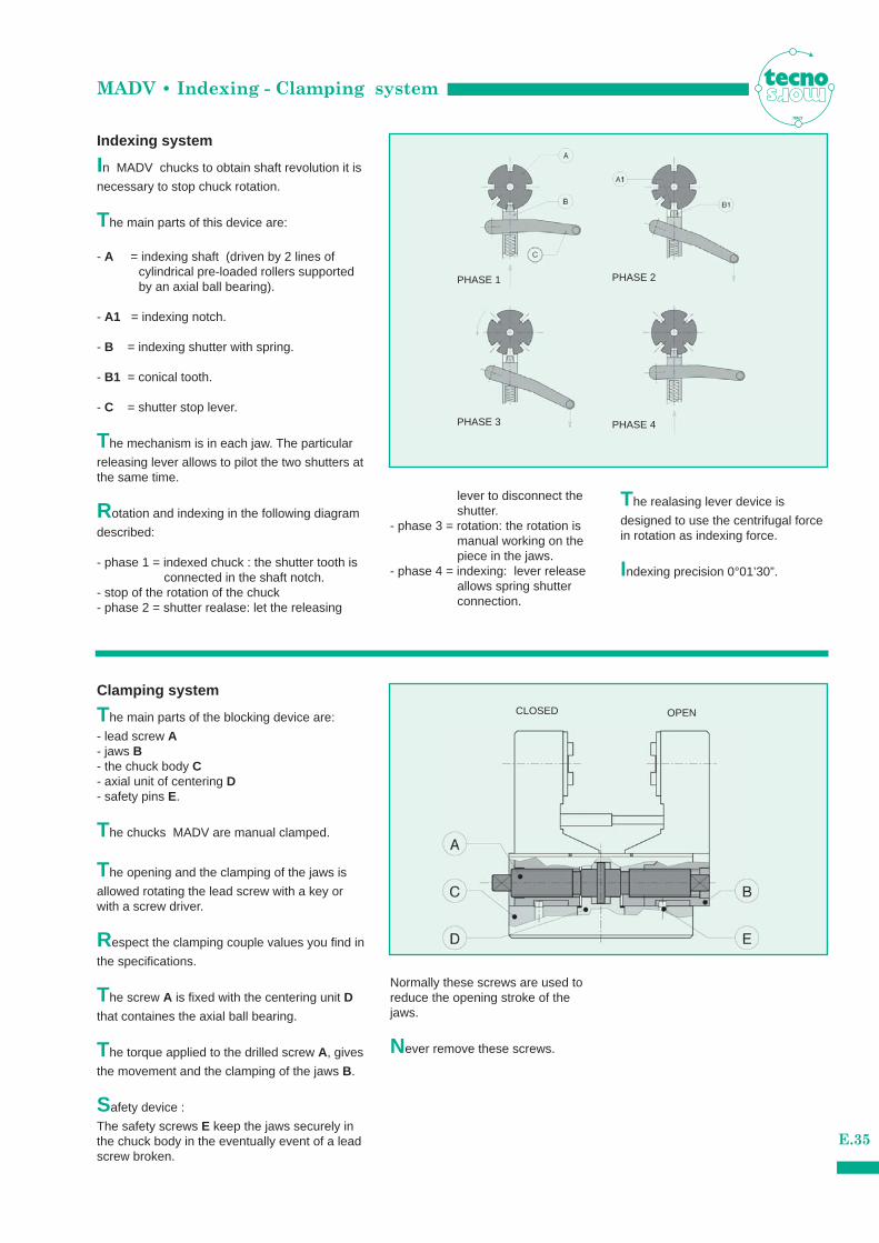
Indexing system
Clamping system
In MADV chucks to obtain shaft revolution it is
necessary to stop chuck rotation.
The main parts of this device are:
- A = indexing shaft (driven by 2 lines of cylindrical pre-loaded rollers supported by an axial ball bearing).
- A1 = indexing notch.
- B = indexing shutter with spring.
- B1 = conical tooth.
- C = shutter stop lever.
The mechanism is in each jaw. The particular
releasing lever allows to pilot the two shutters atthe same time.
Rotation and indexing in the following diagram
described:
- phase 1 = indexed chuck : the shutter tooth is connected in the shaft notch.
- stop of the rotation of the chuck- phase 2 = shutter realase: let the releasing
The main parts of the blocking device are:
- lead screw A- jaws B- the chuck body C - axial unit of centering D- safety pins E.
The chucks MADV are manual clamped.
The opening and the clamping of the jaws is
allowed rotating the lead screw with a key orwith a screw driver.
Respect the clamping couple values you find in
the specifications.
The screw A is fixed with the centering unit D
that containes the axial ball bearing.
The torque applied to the drilled screw A, gives
the movement and the clamping of the jaws B.
Safety device :
The safety screws E keep the jaws securely inthe chuck body in the eventually event of a leadscrew broken.
lever to disconnect the shutter.
- phase 3 = rotation: the rotation is manual working on the piece in the jaws.
- phase 4 = indexing: lever release allows spring shutter connection.
Normally these screws are used toreduce the opening stroke of thejaws.
Never remove these screws.
The realasing lever device is
designed to use the centrifugal forcein rotation as indexing force.
Indexing precision 0°01’30”.
ITALY
PHASE 1
PHASE 3
PHASE 2
PHASE 4
CLOSED OPEN
MADV • Technical specifications
E.36
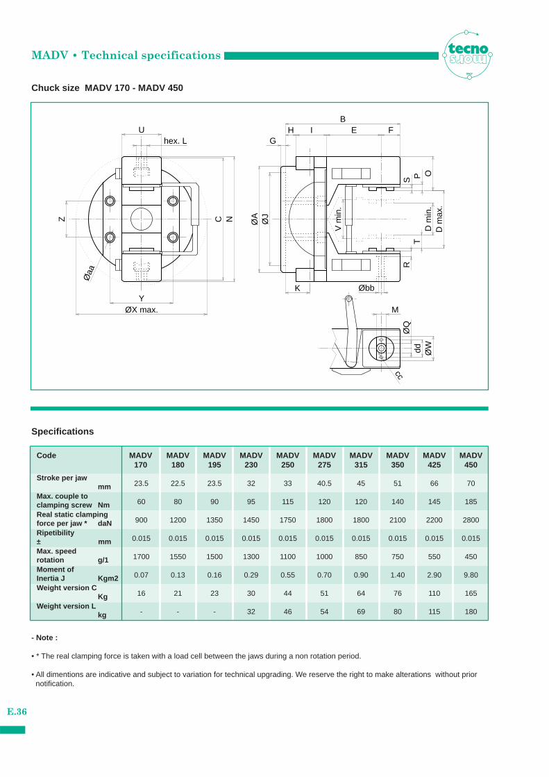
Chuck size MADV 170 - MADV 450
ITALY
Øaa
R
V m
in.
cc
U
Øbb
T
C N
O
S
H
D m
in.
D m
ax.
FE
P
M
hex. L
B
ØA
K
Z
YØX max.
I
ØJ
ØQ
dd ØW
G
Specifications
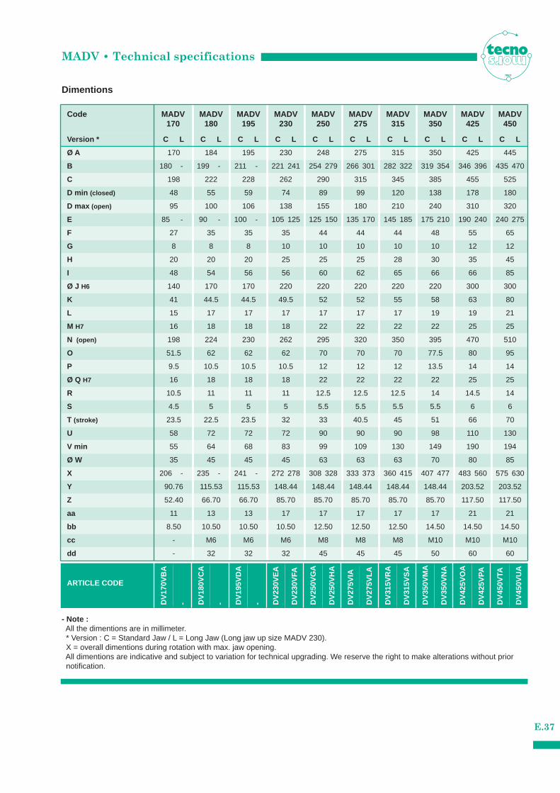
Code MADV MADV MADV MADV MADV MADV MADV MADV MADV MADV170 180 195 230 250 275 315 350 425 450
Stroke per jawmm
Max. speedrotation g/1Moment ofInertia J Kgm2Weight version C
KgWeight version L
kg
- Note :
• * The real clamping force is taken with a load cell between the jaws during a non rotation period.
• All dimentions are indicative and subject to variation for technical upgrading. We reserve the right to make alterations without priornotification.
23.5 22.5 23.5 32 33 40.5 45 51 66 70
Max. couple to clamping screw Nm 60 80 90 95 115 120 120 140 145 185
Real static clamping force per jaw * daN 900 1200 1350 1450 1750 1800 1800 2100 2200 2800
Ripetibility± mm 0.015 0.015 0.015 0.015 0.015 0.015 0.015 0.015 0.015 0.015
1700 1550 1500 1300 1100 1000 850 750 550 450
0.07 0.13 0.16 0.29 0.55 0.70 0.90 1.40 2.90 9.80
16 21 23 30 44 51 64 76 110 165
- - - 32 46 54 69 80 115 180
Dimentions
Code MADV MADV MADV MADV MADV MADV MADV MADV MADV MADV170 180 195 230 250 275 315 350 425 450
Ø A 170 184 195 230 248 275 315 350 425 445
Vers ion * C L C L C L C L C L C L C L C L C L C L
180 - 199 - 211 - 221 241 254 279 266 301 282 322 319 354 346 396 435 470
85 - 90 - 100 - 105 125 125 150 135 170 145 185 175 210 190 240 240 275
206 - 235 - 241 - 272 278 308 328 333 373 360 415 407 477 483 560 575 630
B
C 198 222 228 262 290 315 345 385 455 525
D min (closed) 48 55 59 74 89 99 120 138 178 180
D max (open) 95 100 106 138 155 180 210 240 310 320
E
F 27 35 35 35 44 44 44 48 55 65
G 8 8 8 10 10 10 10 10 12 12
H 20 20 20 25 25 25 28 30 35 45
I 48 54 56 56 60 62 65 66 66 85
Ø J H6 140 170 170 220 220 220 220 220 300 300
K 41 44.5 44.5 49.5 52 52 55 58 63 80
L 15 17 17 17 17 17 17 19 19 21
M H7 16 18 18 18 22 22 22 22 25 25
N (open) 198 224 230 262 295 320 350 395 470 510
O 51.5 62 62 62 70 70 70 77.5 80 95
P 9.5 10.5 10.5 10.5 12 12 12 13.5 14 14
Ø Q H7 16 18 18 18 22 22 22 22 25 25
R 10.5 11 11 11 12.5 12.5 12.5 14 14.5 14
S 4.5 5 5 5 5.5 5.5 5.5 5.5 6 6
T (stroke) 23.5 22.5 23.5 32 33 40.5 45 51 66 70
U 58 72 72 72 90 90 90 98 110 130
V min 55 64 68 83 99 109 130 149 190 194
Ø W 35 45 45 45 63 63 63 70 80 85
X
Y 90.76 115.53 115.53 148.44 148.44 148.44 148.44 148.44 203.52 203.52
Z 52.40 66.70 66.70 85.70 85.70 85.70 85.70 85.70 117.50 117.50
aa 11 13 13 17 17 17 17 17 21 21
bb 8.50 10.50 10.50 10.50 12.50 12.50 12.50 14.50 14.50 14.50
cc
dd
- M6 M6 M6 M8 M8 M8 M10 M10 M10
- 32 32 32 45 45 45 50 60 60
MADV • Technical specifications
E.37
ITALY
- Note :All the dimentions are in millimeter.* Version : C = Standard Jaw / L = Long Jaw (Long jaw up size MADV 230).X = overall dimentions during rotation with max. jaw opening.All dimentions are indicative and subject to variation for technical upgrading. We reserve the right to make alterations without prior notification.
ARTICLE CODE
DV
170V
BA
- DV
180V
CA
- DV
195V
DA
- DV
230V
EA
DV
230V
FA
DV
250V
GA
DV
250V
HA
DV
275V
IA
DV
275V
LA
DV
315V
RA
DV
315V
SA
DV
350V
MA
DV
350V
NA
DV
425V
OA
DV
425V
PA
DV
450V
TA
DV
450V
UA
MADV• Standard supply
E.38
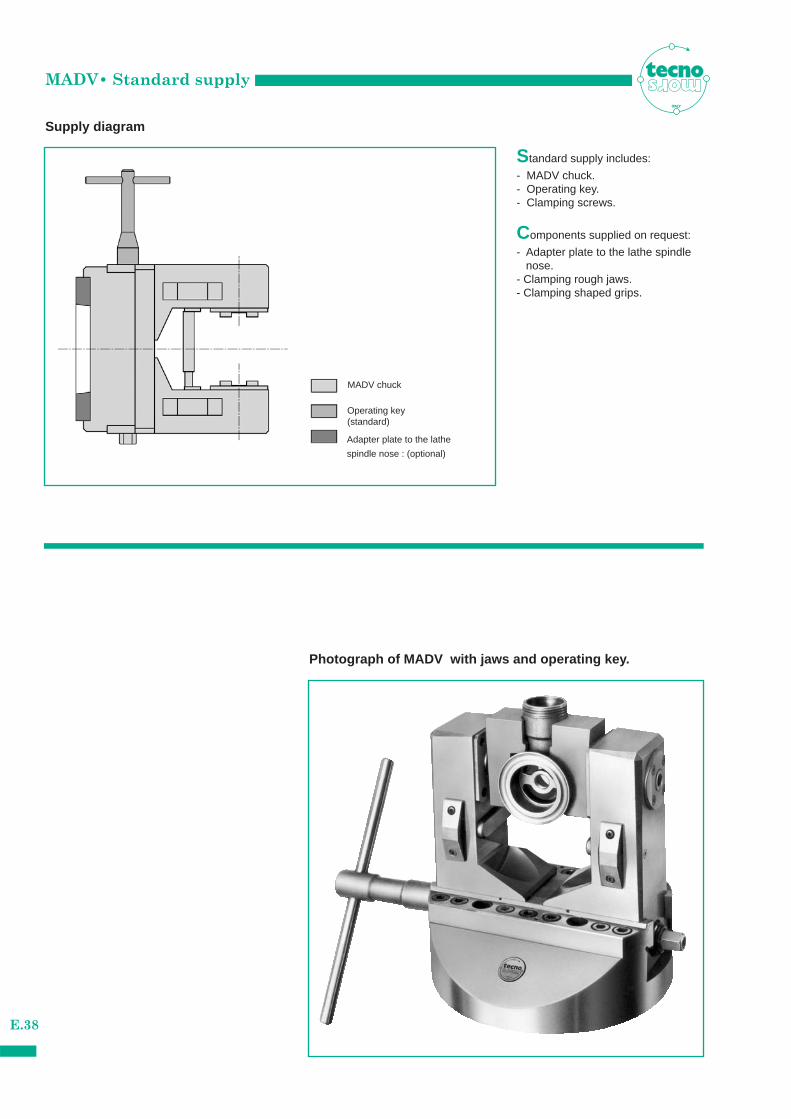
Supply diagram
ITALY
Standard supply includes:
- MADV chuck.- Operating key.- Clamping screws.
Components supplied on request:
- Adapter plate to the lathe spindle nose.
- Clamping rough jaws.- Clamping shaped grips.
Photograph of MADV with jaws and operating key.
MADV chuck
Operating key (standard)
Adapter plate to the lathe
spindle nose : (optional)
MADT • Indexing - Clamping system
E.39
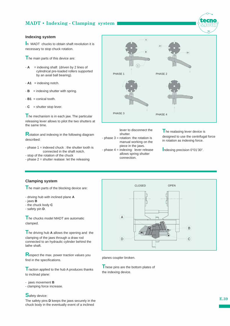
Indexing system
Clamping system
In MADT chucks to obtain shaft revolution it is
necessary to stop chuck rotation.
The main parts of this device are:
- A = indexing shaft (driven by 2 lines of cylindrical pre-loaded rollers supported by an axial ball bearing).
- A1 = indexing notch.
- B = indexing shutter with spring.
- B1 = conical tooth.
- C = shutter stop lever.
The mechanism is in each jaw. The particular
releasing lever allows to pilot the two shutters atthe same time.
Rotation and indexing in the following diagram
described:
- phase 1 = indexed chuck : the shutter tooth is connected in the shaft notch.
- stop of the rotation of the chuck- phase 2 = shutter realase: let the releasing
The main parts of the blocking device are:
- driving hub with inclined plane A- jaws B- the chuck body C- safety pin D.
The chucks model MADT are automatic
clamped.
The driving hub A allows the opening and the
clamping of the jaws through a draw rod connected to an hydraulic cylinder behind thelathe shaft.
Respect the max. power traction values you
find in the specifications.
Traction applied to the hub A produces thanks
to inclinad plane:
- jaws movement B- clamping force increase.
Safety device:
The safety pins D keeps the jaws securely in thechuck body in the eventually event of a inclined
lever to disconnect the shutter.
- phase 3 = rotation: the rotation is manual working on the piece in the jaws.
- phase 4 = indexing: lever release allows spring shutter connection.
planes coupler broken.
These pins are the bottom plates of
the indexing device.
The realasing lever device is
designed to use the centrifugal forcein rotation as indexing force.
Indexing precision 0°01’30”.
ITALY
PHASE 1 PHASE 2
PHASE 3 PHASE 4
CLOSED OPEN
MADT • Technical specifications
E.40
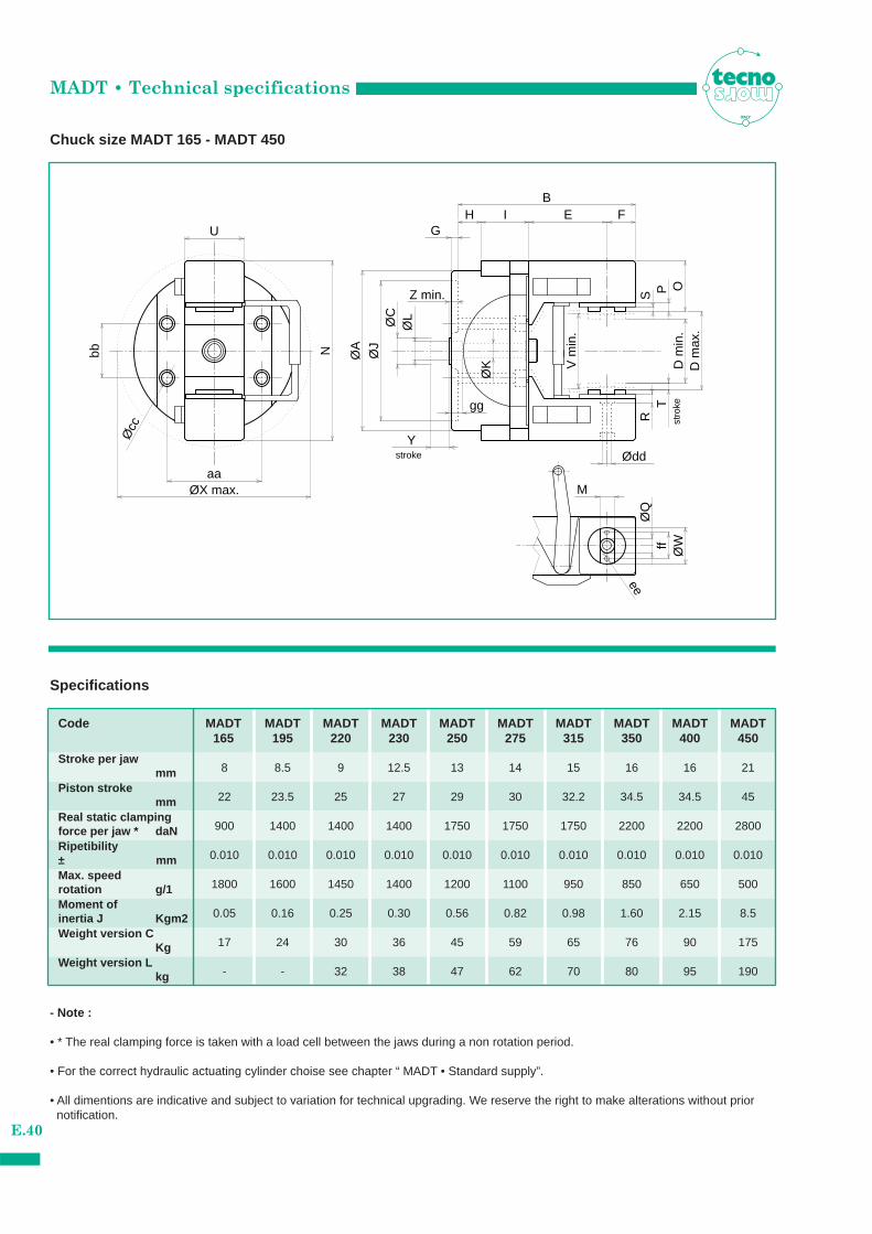
Chuck size MADT 165 - MADT 450
ITALY
Øcc
Z min.
gg T
ØK V
min
.
ee
stro
ke
stroke Ødd
ØJ
I
Y
aaØX max.
O
E
PR
ØW
M
D m
in.
D m
ax.
Sff
ØQ
bb
BH
U
N
F
ØA
ØC
ØL
G
Specifications
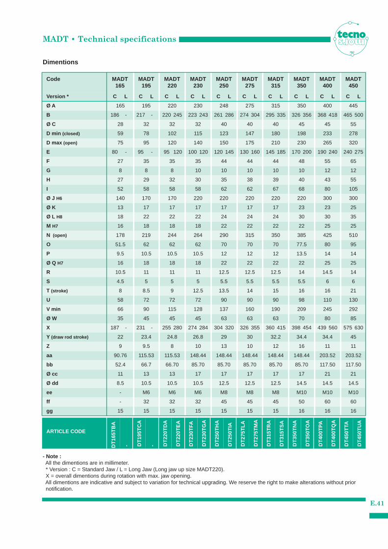
Code MADT MADT MADT MADT MADT MADT MADT MADT MADT MADT165 195 220 230 250 275 315 350 400 450
Stroke per jawmm
Max. speedrotation g/1Moment of inertia J Kgm2Weight version C
KgWeight version L
kg
- Note :
• * The real clamping force is taken with a load cell between the jaws during a non rotation period.
• For the correct hydraulic actuating cylinder choise see chapter “ MADT • Standard supply”.
• All dimentions are indicative and subject to variation for technical upgrading. We reserve the right to make alterations without prior notification.
8 8.5 9 12.5 13 14 15 16 16 21
Piston strokemm 22 23.5 25 27 29 30 32.2 34.5 34.5 45
Real static clamping force per jaw * daN 900 1400 1400 1400 1750 1750 1750 2200 2200 2800
Ripetibility± mm 0.010 0.010 0.010 0.010 0.010 0.010 0.010 0.010 0.010 0.010
1800 1600 1450 1400 1200 1100 950 850 650 500
0.05 0.16 0.25 0.30 0.56 0.82 0.98 1.60 2.15 8.5
17 24 30 36 45 59 65 76 90 175
- - 32 38 47 62 70 80 95 190
Dimentions
Code MADT MADT MADT MADT MADT MADT MADT MADT MADT MADT165 195 220 230 250 275 315 350 400 450
Ø A 165 195 220 230 248 275 315 350 400 445
Vers ion * C L C L C L C L C L C L C L C L C L C L
186 - 217 - 220 245 223 243 261 286 274 304 295 335 326 356 368 418 465 500
80 - 95 - 95 120 100 120 120 145 130 160 145 185 170 200 190 240 240 275
187 - 231 - 255 280 274 284 304 320 326 355 360 415 398 454 439 560 575 630
B
Ø C 28 32 32 32 40 40 40 45 45 55
D min (closed) 59 78 102 115 123 147 180 198 233 278
D max (open) 75 95 120 140 150 175 210 230 265 320
E
F 27 35 35 35 44 44 44 48 55 65
G 8 8 8 10 10 10 10 10 12 12
H 27 29 32 30 35 38 39 40 43 55
I 52 58 58 58 62 62 67 68 80 105
Ø J H6 140 170 170 220 220 220 220 220 300 300
Ø K 13 17 17 17 17 17 17 23 23 25
Ø L H8 18 22 22 22 24 24 24 30 30 35
M H7 16 18 18 18 22 22 22 22 25 25
N (open) 178 219 244 264 290 315 350 385 425 510
O 51.5 62 62 62 70 70 70 77.5 80 95
P 9.5 10.5 10.5 10.5 12 12 12 13.5 14 14
Ø Q H7 16 18 18 18 22 22 22 22 25 25
R 10.5 11 11 11 12.5 12.5 12.5 14 14.5 14
S 4.5 5 5 5 5.5 5.5 5.5 5.5 6 6
T (stroke) 8 8.5 9 12.5 13.5 14 15 16 16 21
U 58 72 72 72 90 90 90 98 110 130
V min 66 90 115 128 137 160 190 209 245 292
Ø W 35 45 45 45 63 63 63 70 80 85
X
Y (draw rod stroke) 22 23.4 24.8 26.8 29 30 32.2 34.4 34.4 45
Z 9 9.5 8 10 13 10 12 16 11 11
aa 90.76 115.53 115.53 148.44 148.44 148.44 148.44 148.44 203.52 203.52
bb 52.4 66.7 66.70 85.70 85.70 85.70 85.70 85.70 117.50 117.50
Ø cc
Ø dd
11 13 13 17 17 17 17 17 21 21
8.5 10.5 10.5 10.5 12.5 12.5 12.5 14.5 14.5 14.5
ee - M6 M6 M6 M8 M8 M8 M10 M10 M10
ff - 32 32 32 45 45 45 50 60 60
gg 15 15 15 15 15 15 15 16 16 16
MADT • Technical specifications
E.41
ITALY
- Note :All the dimentions are in millimeter.* Version : C = Standard Jaw / L = Long Jaw (Long jaw up size MADT220).X = overall dimentions during rotation with max. jaw opening.All dimentions are indicative and subject to variation for technical upgrading. We reserve the right to make alterations without prior notification.
ARTICLE CODE
DT
165T
BA
- DT
195T
CA
- DT
220T
DA
DT
220T
EA
DT
230T
FA
DT
230T
GA
DT
250T
HA
DT
250T
IA
DT
275T
LA
DT
275T
MA
DT
315T
RA
DT
315T
SA
DT
350T
NA
DT
350T
OA
DT
400T
PA
DT
400T
QA
DT
450T
TA
DT
450T
UA
MADT• Standard supply
E.42
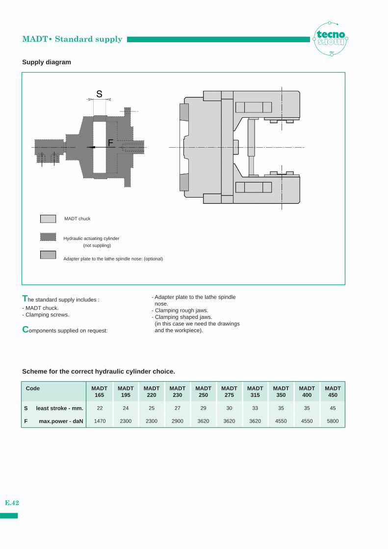
Supply diagram
ITALY
The standard supply includes :
- MADT chuck.- Clamping screws.
Components supplied on request:
- Adapter plate to the lathe spindle nose.
- Clamping rough jaws.- Clamping shaped jaws.
(in this case we need the drawings and the workpiece).
Scheme for the correct hydraulic cylinder choice.
Code MADT MADT MADT MADT MADT MADT MADT MADT MADT MADT165 195 220 230 250 275 315 350 400 450
S least stroke - mm. 22 24 25 27 29 30 33 35 35 45
F max.power - daN 1470 2300 2300 2900 3620 3620 3620 4550 4550 5800
MADT chuck
Hydraulic actuating cylinder
(not suppling)
Adapter plate to the lathe spindle nose: (optional)
EquipmentITALY
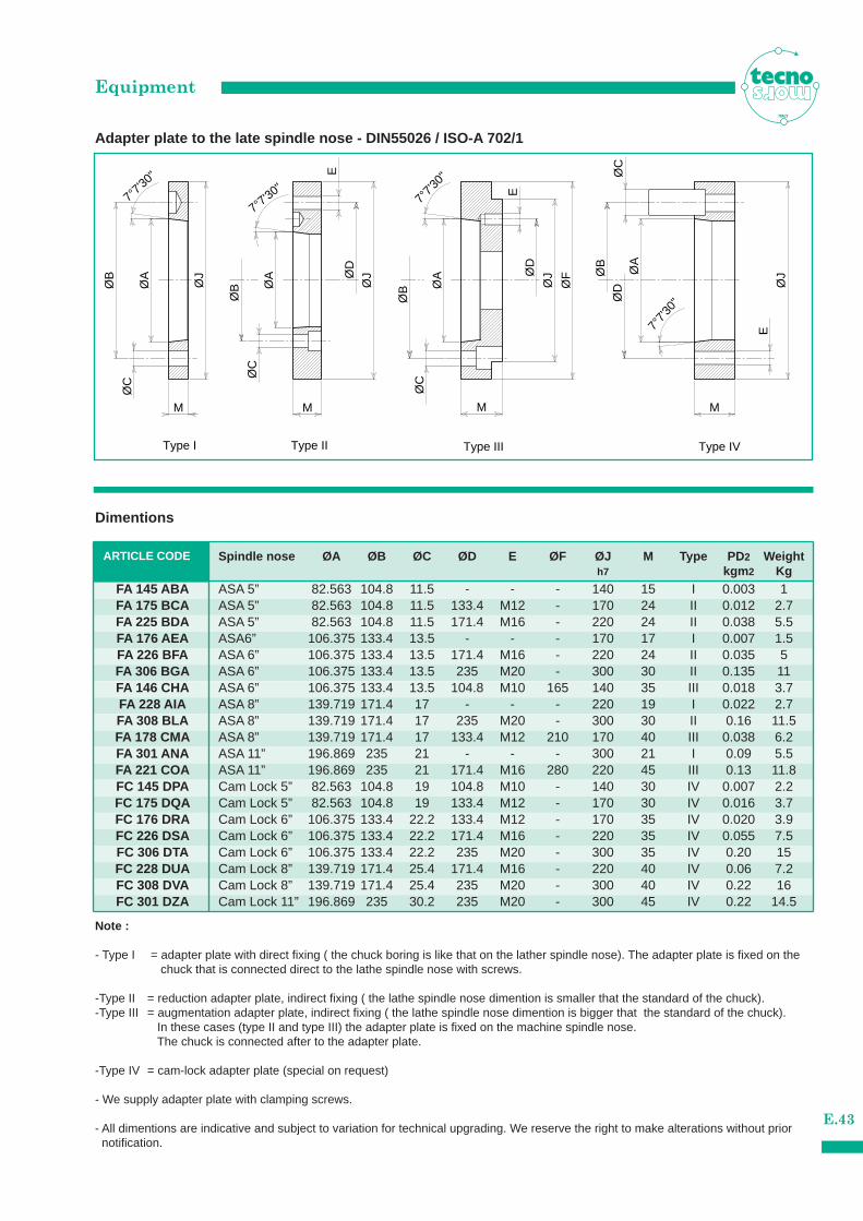
Spindle nose ØA ØB ØC ØD E ØF ØJ M Type PD 2 Weighth7 kgm 2 Kg
Note :
- Type I = adapter plate with direct fixing ( the chuck boring is like that on the lather spindle nose). The adapter plate is fixed on the chuck that is connected direct to the lathe spindle nose with screws.
-Type II = reduction adapter plate, indirect fixing ( the lathe spindle nose dimention is smaller that the standard of the chuck).-Type III = augmentation adapter plate, indirect fixing ( the lathe spindle nose dimention is bigger that the standard of the chuck).
In these cases (type II and type III) the adapter plate is fixed on the machine spindle nose.The chuck is connected after to the adapter plate.
-Type IV = cam-lock adapter plate (special on request)
- We supply adapter plate with clamping screws.
- All dimentions are indicative and subject to variation for technical upgrading. We reserve the right to make alterations without prior notification.
ARTICLE CODE
7°7'3
0"
7°7'3
0"
7°7'30" E
7°7'3
0"
E
ØB
Type I
ØB
ØD
ØB
ØD
ØD
Type II Type IVType III
M MØ
C
ØC
ØC
ØB
ØA
ØJ
ØA
ØA
ØJ
M
ØJ
M
ØC
E
ØF
ØJØ
A
Adapter plate to the late spindle nose - DIN55026 / ISO-A 702/1
FA 145 ABAFA 175 BCAFA 225 BDAFA 176 AEAFA 226 BFAFA 306 BGAFA 146 CHAFA 228 AIAFA 308 BLAFA 178 CMAFA 301 ANAFA 221 COAFC 145 DPAFC 175 DQAFC 176 DRAFC 226 DSAFC 306 DTAFC 228 DUAFC 308 DVAFC 301 DZA
ASA 5” 82.563 104.8 11.5 - - - 140 15 I 0.003 1ASA 5” 82.563 104.8 11.5 133.4 M12 - 170 24 II 0.012 2.7ASA 5” 82.563 104.8 11.5 171.4 M16 - 220 24 II 0.038 5.5ASA6” 106.375 133.4 13.5 - - - 170 17 I 0.007 1.5ASA 6” 106.375 133.4 13.5 171.4 M16 - 220 24 II 0.035 5ASA 6” 106.375 133.4 13.5 235 M20 - 300 30 II 0.135 11ASA 6” 106.375 133.4 13.5 104.8 M10 165 140 35 III 0.018 3.7ASA 8” 139.719 171.4 17 - - - 220 19 I 0.022 2.7ASA 8” 139.719 171.4 17 235 M20 - 300 30 II 0.16 11.5ASA 8” 139.719 171.4 17 133.4 M12 210 170 40 III 0.038 6.2ASA 11” 196.869 235 21 - - - 300 21 I 0.09 5.5ASA 11” 196.869 235 21 171.4 M16 280 220 45 III 0.13 11.8Cam Lock 5” 82.563 104.8 19 104.8 M10 - 140 30 IV 0.007 2.2Cam Lock 5” 82.563 104.8 19 133.4 M12 - 170 30 IV 0.016 3.7Cam Lock 6” 106.375 133.4 22.2 133.4 M12 - 170 35 IV 0.020 3.9Cam Lock 6” 106.375 133.4 22.2 171.4 M16 - 220 35 IV 0.055 7.5Cam Lock 6” 106.375 133.4 22.2 235 M20 - 300 35 IV 0.20 15Cam Lock 8” 139.719 171.4 25.4 171.4 M16 - 220 40 IV 0.06 7.2Cam Lock 8” 139.719 171.4 25.4 235 M20 - 300 40 IV 0.22 16Cam Lock 11” 196.869 235 30.2 235 M20 - 300 45 IV 0.22 14.5
Dimentions
E.43

NotesITALY
E.44

NotesITALY
E.45