Embed Size (px)
Citation preview
INSTRUCTIONS P_T,ZMI_Ry OEK-2499OA
DC-3062 SCR POWER CONVERSION MODULES
THREE PHASE FULL WAVE
OPERATION TROUBLESHOOTING
These instructtons do not purport to cover all details or variations in equipment nor to provtde for every possible contingency to be met in connection wtth
installation, operation or maintenance. Should further mformation be desired or should particular problems arise which are not covered sufficiently for the
purchaser's purposes, the matter should be referred to the General Electric Company
GENERAL ELECTRIC
THREE PHASE FULL WAVE POWER CONVERSION MODULES
TABLE OF CONTENTS
General Page
Description 3
RatingsandSpecifications 3ACPowerInput 3
DCPowerOutput 3ControlInput 3
ControlOutput 4
PrinciplesofOperation 4
SCRPowerConversion 4ProtectiveComponents 6
FeedbackCircuitry 6
Start-UR 7
Troubleshooting 7
GeneralApproach 7
CheckingforMalfunctions 8
VoltageWaveShapeChecklist 11
RepairandReplacement 11
WARNING
HIGH VOLTAGE. ELECTRIC SHOCK CAN CAUSE SERIOUS OR FATAL INJURY.
WHETHER THE AC VOLTAGE SUPPLY IS GROUNDED OR NOT, HIGH VOLTAGESTO GROUND WILL BE PRESENT AT MANY POINTS WITHIN THE SCR DRIVE.
EXTREME CARE MUST BE EXERCISED IN THE SELECTION AND USE OF TESTINSTRUMENTS.
OPERATORS SHOULD NOT STAND ON GROUNDED SURFACES OR BE IN CONTACT
WITH GROUND WHEN APPLYING TEST INSTRUMENTS TO TEST POINTS. TEST
INSTRUMENTS SHOULD NOT HAVE CHASSIS GROUNDED WHILE TESTS ARE BE-ING MADE. THUS THEIR CHASSIS WiLL BE AT A HIGH VOLTAGE WITH
RESPECT TO GROUND DURING TESTING. EXTREME CARE SHOULD BE TAKEN
WHILE ATTEMPTING TO ADJUST, TROUBLESHOOT OR MAINTAIN ANY DRIVESYSTEM DESCRIBED HEREIN°
INSTRUCTIONS GEK-24990AERRATASHEETNUMBERJUNE, 1978
DC-3062 SCR POWER CONVERSION MODULES
THREE PHASE FULL WAVE
OPERATION TROUBLESHOOTING
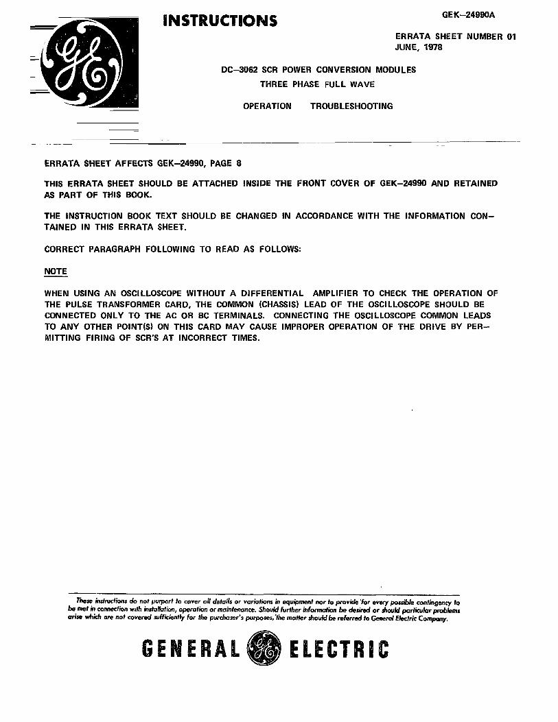
ERRATA SHEET AFFECTS GEK-24990, PAGE 8
THIS ERRATA SHEET SHOULD BE ATTACHED INSIDE THE FRONT COVER OF GEK--24990 AND RETAINEDAS PART OF THIS BOOK.
THE INSTRUCTION BOOK TEXT SHOULD BE CHANGED IN ACCORDANCE WITH THE INFORMATION CON-TAINED IN THIS ERRATA SHEET.
CORRECT PARAGRAPH FOLLOWING TO READ AS FOLLOWS:
NOTE
WHEN USING AN OSCILLOSCOPE WITHOUT A DIFFERENTIAL AMPLIFIER TO CHECK THE OPERATION OFTHE PULSE TRANSFORMER CARD, THE COMMON (CHASSIS) LEAD OF THE OSCILLOSCOPE SHOULD BECONNECTED ONLY TO THE AC OR BC TERMINALS. CONNECTING THE OSCILLOSCOPE COMMON LEADSTO ANY OTHER POINT(S) ON THIS CARD MAY CAUSE IMPROPER OPERATION OF THE DRIVE BY PER-MITTING FIRING OF SCR'S AT INCORRECT TIMES.
Theminsfnuctionsdo notpurportto coveralldetailsor variationsinequipmentnortoprovide'foreverypossiblecontingencyfobemetinconnectionw_thinstallation,operationormaintenance.Shouldfurther/nformaf/onbedesiredor shouldparticularproblemsarisewhicharenotcoveredsufficientlyfor thepurchaser'spurposes,'themattershouMbereferredtoGeneralElectricCompany.
GENERAL0 ELECTRIC
THREE PHASE FULL WAVE POWER CONVERSION MODULES
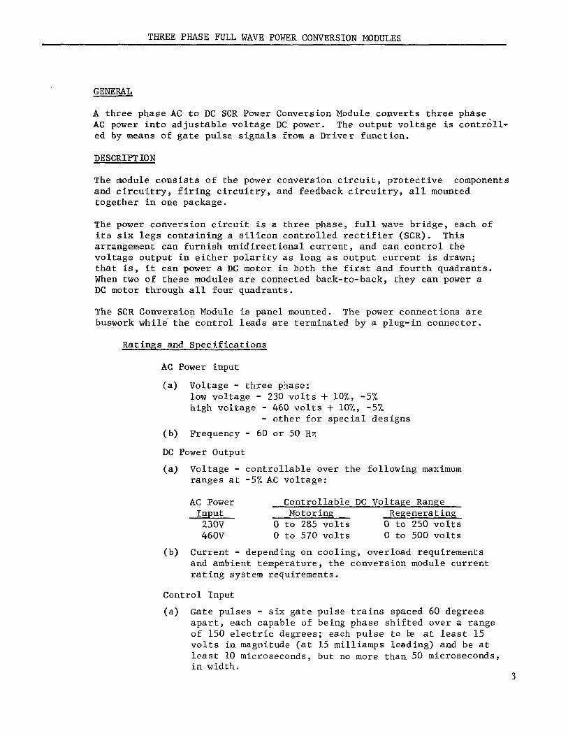
GENERAL
A three phase AC to DC SCR Power Conversion Module converts three phase
AC power into adjustable voltage DC power. The output voltage is controll-
ed by means of gate pulse signals from a Driver function.
DESCRIPTION
The module consists of the power conversion circuit, protective components
and circuitry, firing circuitry, and feedback circuitry, all mounted
together in one package.
The power conversion circuit is a three phase, full wave bridge, each of
its six legs containing a silicon controlled rectifier (SCR). This
arrangement can furnish unidirectional current, and can control the
voltage output in either polarity as long as output current is drawn;
that is, it can power a DC motor in both the first and fourth quadrants.
When two of these modules are connected back-to-back, they can power a
DC motor through all four quadrants.
The SCR Conversion Module is panel mounted. The power connections are
buswork while the control leads are terminated by a plug-in connector.
Ratings and Specifications
AC Power input
(a) Voltage - three phase:
low voltage - 230 volts + 10%, -5%
high voltage - 460 volts + 10%, -5%
- other for special designs
(b) Frequency - 60 or 50 Hz
DC Power Output
(a) Voltage - controllable over the following maximum
ranges at -5% AC voltage:
AC Power Controllable DC Voltage Range
Input Motoring Regenerating230V 0 to 285 volts 0 to 250 volts
460V 0 to 570 volts 0 to 500 volts
(b) Current - depending on cooling, overload requirements
and ambient temperature, the conversion module current
rating system requirements.
Control Input
(a) Gate pulses - six gate pulse trains spaced 60 degrees
apart, each capable of being phase shifted over a range
of 150 electric degrees; each pulse to _ at least 15
volts in magnitude (at 15 milliamps loading) and be at
least t0 microseconds, but no more than 50 microseconds,in width.
3
THREE PHASE FULL WAVE POWER CONVERSION MODULES
(b) Power Supply: +20 volts DC for operation of gate pulseamplifying circuitry.
Control Output
(a) Current Feedback - 0 to approximately +2.5 volts DC for
rated operating current range.
(b) Thermoswitch Interlock - normally closed interlock which opens
for excessive Conversion Module temperature due to loss of
cooling air.
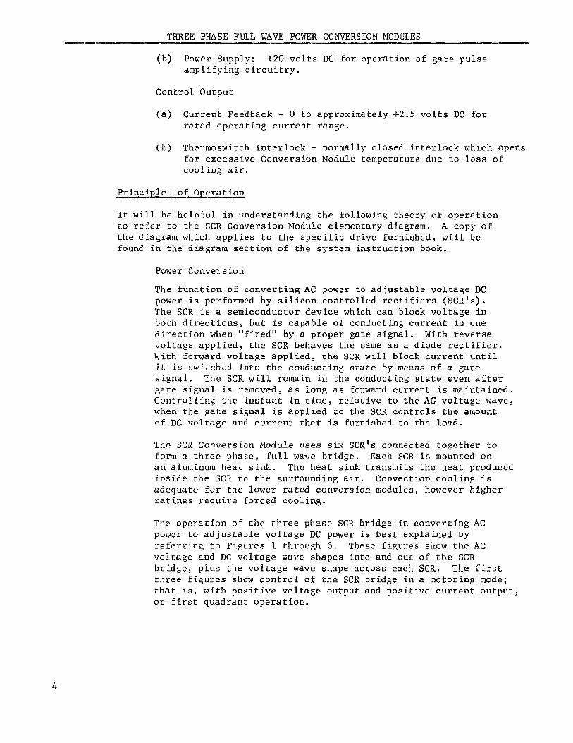
Principles of Operation
It will be helpful in understanding the following theory of operation
to refer to the SCR Conversion Module elementary diagram. A copy of
the diagram which applies to the specific drive furnished, will be
found in the diagram section of the system instruction book.
Power Conversion
The function of converting AC power to adjustable voltage DC
power is performed by silicon controlled rectifiers (SCR's).
The SCR is a semiconductor device which can block voltage in
both directions, but is capable of conducting current in one
direction when "fired" by a proper gate signal. With reverse
voltage applied, the SCR behaves the same as a diode rectifier.
With forward voltage applied, the SCR will block current until
it is switched into the conducting state by means of a gatesignal. The SCR will remain in the conducting state even after
gate signal is removed, as long as forward current is maintained.
Controlling the instant in time, relative to the AC voltage wave,
when the gate signal is applied to the SCR controls the amountof DC voltage and current that is furnished to the load.
The SCR Conversion Module uses six SCR's connected together to
form a three phase, full wave bridge. Each SCR is mounted on
an aluminum heat sink. The heat sink transmits the heat produced
inside the SCR to the surrounding air. Convection cooling is
adequate for the lower rated conversion modules, however higher
ratings require forced cooling.
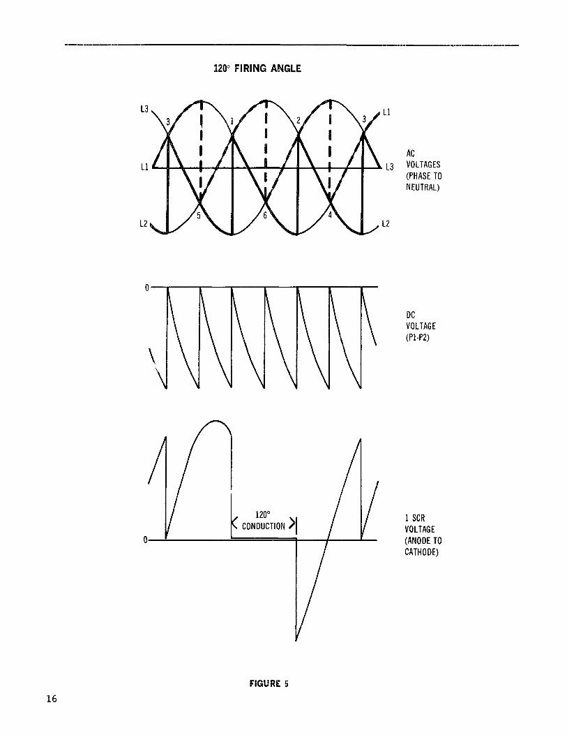
The operation of the three phase SCR bridge in converting ACpower to adjustable voltage DC power is best explained by
referring to Figures 1 through 6. These figures show the AC
voltage and DC voltage wave shapes into and out of the SCR
bridge, plus the voltage wave shape across each SCR. The first
three figures show control of the SCR bridge in a motoring mode;
that is, with positive voltage output and positive current output,or first quadrant operation.
THREE PHASE FULL WAVE POWER CONVERSION MODULES
(continued)
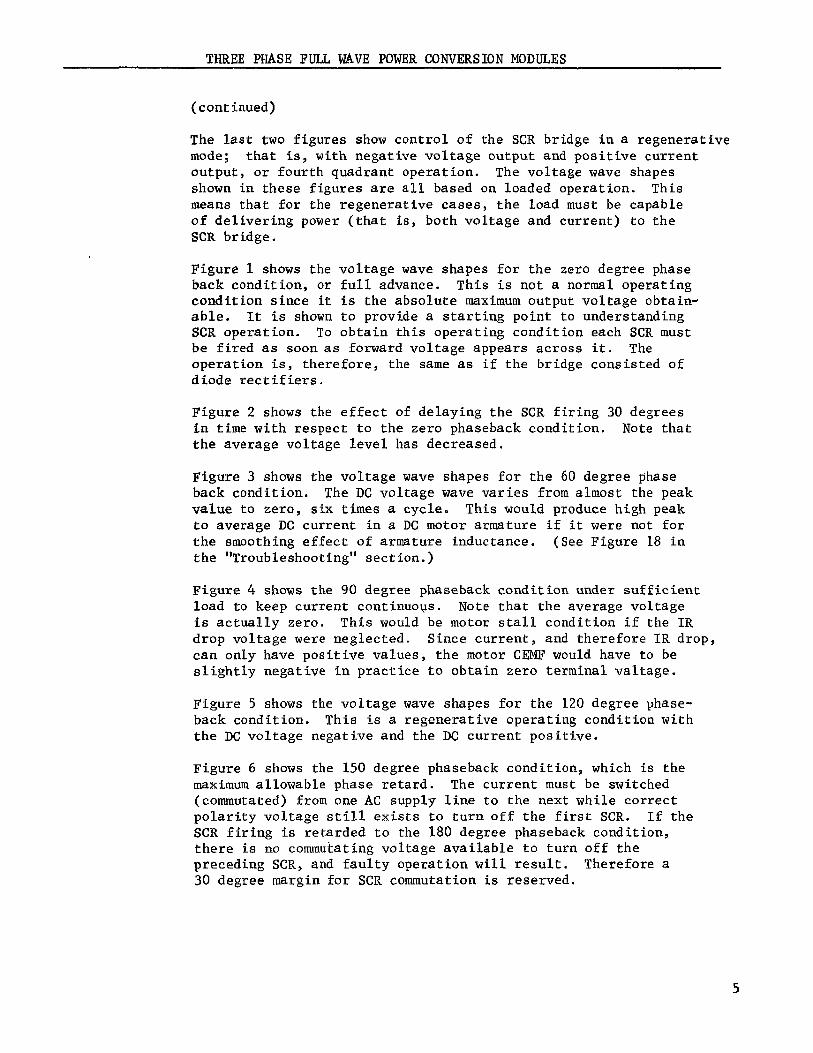
The last two figures show control of the SCR bridge in a regenerative
mode; that is, with negative voltage output and positive current
output, or fourth quadrant operation. The voltage wave shapes
shown in these figures are all based on loaded operation. This
means that for the regenerative cases, the load must be capable
of delivering power (that is, both voltage and current) to the
SCR bridge.
Figure 1 shows the voltage wave shapes for the zero degree phaseback condition, or full advance. This is not a normal operating
condition since it is the absolute maximum output voltage obtain-
able. It is shown to provide a starting point to understanding
$CR operation. To obtain this operating condition each SCR must
be fired as soon as forward voltage appears across it. The
operation is, therefore, the same as if the bridge consisted ofdiode rectifiers.
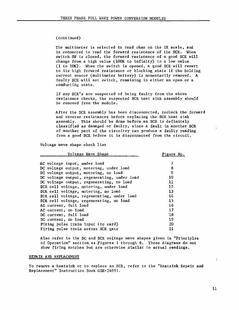
Figure 2 shows the effect of delaying the SCR firing 30 degrees
in time with respect to the zero phaseback condition. Note that
the average voltage level has decreased.
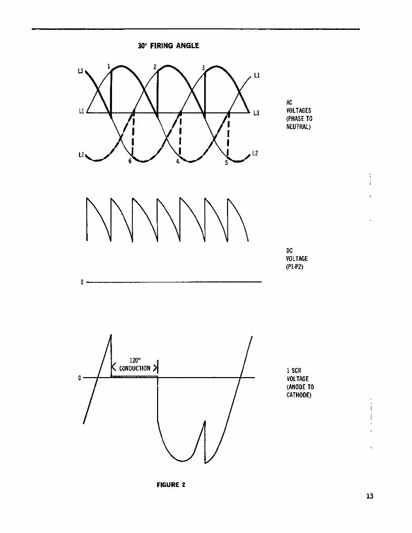
Figure 3 shows the voltage wave shapes for the 60 degree phase
back condition. The DC voltage wave varies from almost the peak
value to zero, six times a cycle. This would produce high peak
to average DC current in a DC motor armature if it were not for
the smoothing effect of armature inductance. (See Figure 18 in
the "Troubleshooting" section.)
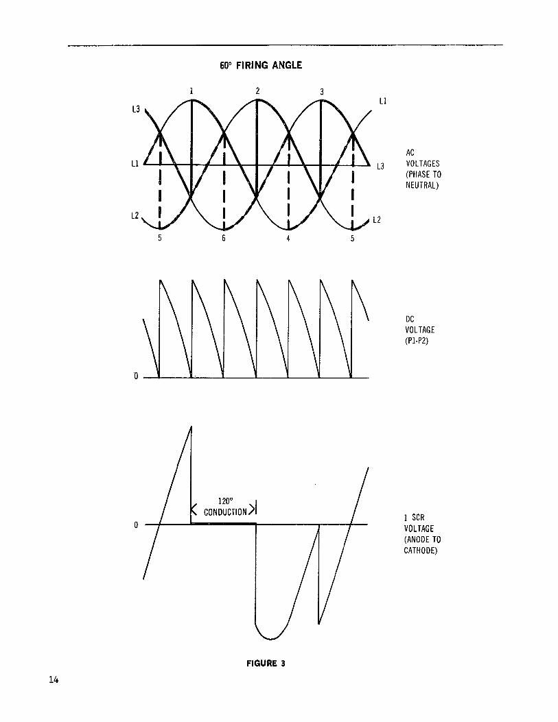
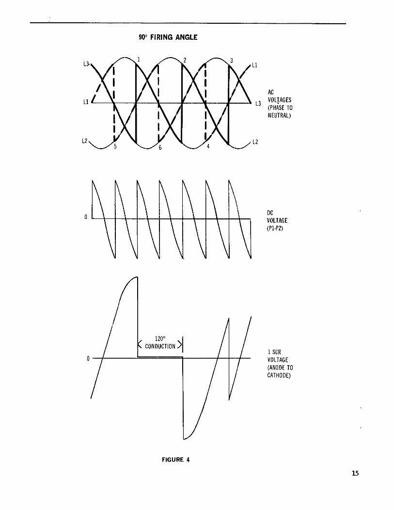
Figure 4 shows the 90 degree phaseback condition under sufficient
load to keep current continuous. Note that the average voltage
is actually zero. This would be motor stall condition if the IR
drop voltage were neglected. Since current, and therefore IR drop,
can only have positive values, the motor CEMF would have to be
slightly negative in practice to obtain zero terminal valtage.
Figure 5 shows the voltage wave shapes for the 120 degree phase-
back condition. This is a regenerative operating condition with
the DC voltage negative and the DC current positive.
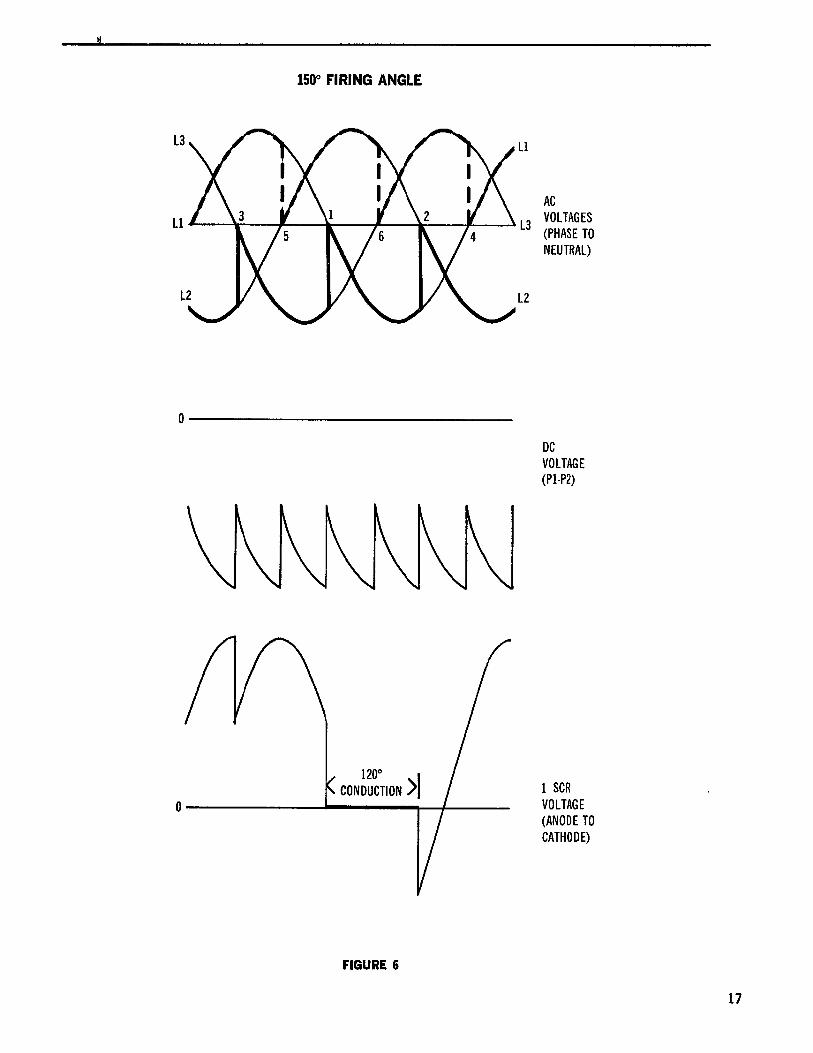
Figure 6 shows the 150 degree phaseback condition, which is the
maximum allowable phase retard. The current must be switched
(commutated) from one AC supply line to the next while correct
polarity voltage still exists to turn off the first SCR. If the
SCR firing is retarded to the 180 degree phaseback condition,
there is no commutating voltage available to turn off the
preceding SCR, and faulty operation will result. Therefore a
30 degree margin for SCR commutation is reserved.
5
THREE PHASE FULL WAVE POWER CONVERSION MODULES
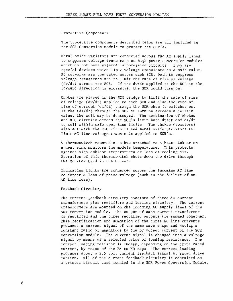
Protective Components
The protective components described below are all included in
the SCR Conversion Module to protect the SCR's.
Metal oxide varistors are connected across the AC supply lines
to suppress voltage transients on high power conversion modules
which do not have external suppression circuits. They are
special devices which limit voltage transients to a safe value.
RC networks are connected across each SCR, both to suppress
voltage transients and to limit the rate of rise of voltage
(dv/dt) across the SCR. If the dv/dt applied to the SCR in the
forward direction is excessive, the SCR could turn on.
Chokes are placed in the SCR bridge to limit the rate of rise
of voltage (dv/dt) applied to each SCR and also the rate of
rise of current (di/dt) through the SCR when it switches on.
If the (di/dt) through the SCR at turn-on exceeds a certain
value, the cell may be destroyed. The combination of chokesand R-C circuits across the SCR's limit both dv/dt and di/dt
to well within safe operating limits. The chokes (reactors)also act with the R-C circuits and metal oxide varistors to
limit AC line voltage transients applied to SCR's.
A thermoswitch mounted on a bus attached to a heat sink or on
a heat sink monitors the module temperature. This protects
against high ambient temperatures or loss of cooling air.
Operation of this thermoswitch shuts down the drive throughthe Monitor Card in the Driver.
Indicating lights are connected across the incoming AC line
to detect a loss of phase voltage (such as the failure of an
AC line fuse).
Feedback Circuitry
The current feedback circuitry consists of three AC current
transformers plus rectifiers and loading circuitry. The current
transformers are mounted on the incoming AC supply lines of the
SCR conversion module. The output of each current transformer
is rectified and the three rectified outputs are summed together.This rectification and summation of the three AC line currents
produces a current signal of the same wave shape and having a
constant ratio of magnitude to the DC output current of the $CR
conversion module° The current signal is changed into a voltage
signal by means of a selected value of loading resistance. The
correct loading resistor is chosen, depending on the drive rated
current, by means of the XA to XD taps° The correct loading
produces about a 2.5 volt current feedback signal at rated drive
current. All of the current feedback circuitry is contained on
a printed circuit card mounted in the SCR Power Conversion Module.
THREE PHASE FULL WAVE POWER CONVERSION MODULES
(continued)
The table on the SCR Conversion Module elementary diagram
gives the correct tap (XA to XD) to use for the specific
drive horsepower rating.
START-UP
The Power Conversion Module is ready for operation when ventilation is
proper and three phase power of 1, 2, 3 sequence is applied to the SCR
Conversion Module input terminals (Ti, T2 and T3) and when the controlharness has been connected to the Driver.
TROUBLESHOOT ING
General Approach
When incorrect operation is first noticed, it is often possible to
reduce the overall servicing time by studying the symptoms in order
to localize the trouble. A good understanding of the functional
operation, as explained in the "Principles of Operation" section,
will be very helpful in isolating the problem. A systematic check
of voltage wave shapes and comparison of them with the correct
readings, as given later in this section, should reveal the source
of many malfunctions.
The use of a good quality oscilloscope is required to properlytroubleshoot this equipment.
WARNING
HIGH VOLTAGE. ELECTRIC SHOCK CAN CAUSE SERIOUS OR FATAL INJURY.
WHETHER THE AC VOLTAGE SUPPLY IS GROUNDED OR NOT, HIGH VOLTAGESTO 'GROUND WILL BE PRESENT AT MANY POINTS WITHIN THE SCR DRIVE.
EXTREME CARE MUST BE EXERCISED IN THE SELECTION AND USE OF TEST
INSTRUMENTS.
OPERATORS SHOULD NOT STAND ON GROUNDED SURFACES OR BE IN CONTACT
WITH GROUND WHEN APPLYING TEST INSTRUMENTS TO TEST POINTS. TEST
INSTRUMENTS SHOULD NOT HAVE CHASSIS GROUNDED WHILE TESTS ARE
BEING MADE. EXTREME CARE SHOULD BE TAKEN DURING THE USE OF TEST
INSTRUMENTS, SUCH AS AN OSCILLOSCOPE, SINCE THEIR CHASSIS WILL BEAT A HIGH VOLTAGE WITH RESPECT TO GROUND DURING TESTING.
The use of an oscilloscope with a differential amplifier will
result in much greater safety to operating personnel, since the
oscilloscope chassis may then be grounded. However, much greater
care in the selection of probes and leads and in the adjustment
of the oscilloscope must be used to produce accurate readings.
The DC balance and the voltage gain calibration of each channel
must be accurately adjusted to obtain common mode voltage rejection.
THREE PHASE FULL WAVE POWER CONVERSION MODULES
(continued)
When properly adjusted, good results can be obtained with the differ-ential amplifier connected oscilloscope for most readings. However,
unless the common mode voltage rejection is perfect, it may be difficultto obtain accurate readings of low voltages such as SCR gate signals.
No matter which oscilloscope connection is used, voltage attenuating
probes will be required for most readings. The probes should be adjusted
for correct frequency compensation using the voltage calibrator as a
square wave standard. The vertical gain and the sweep should also becalibrated to allow interpretation of observations.
Checking for Malfunctions
NO_T__E
When using an oscilloscope without a differential amplifier to checkthe operation of the pulse transformer card, the common (chassis) lead
of the oscilloscope should be connected only to the F or C terminals.
Connecting the oscilloscope common leads to any other point(s) on thiscard may cause improper operation of the drive by permitting firing ofSCR's at incorrect times.
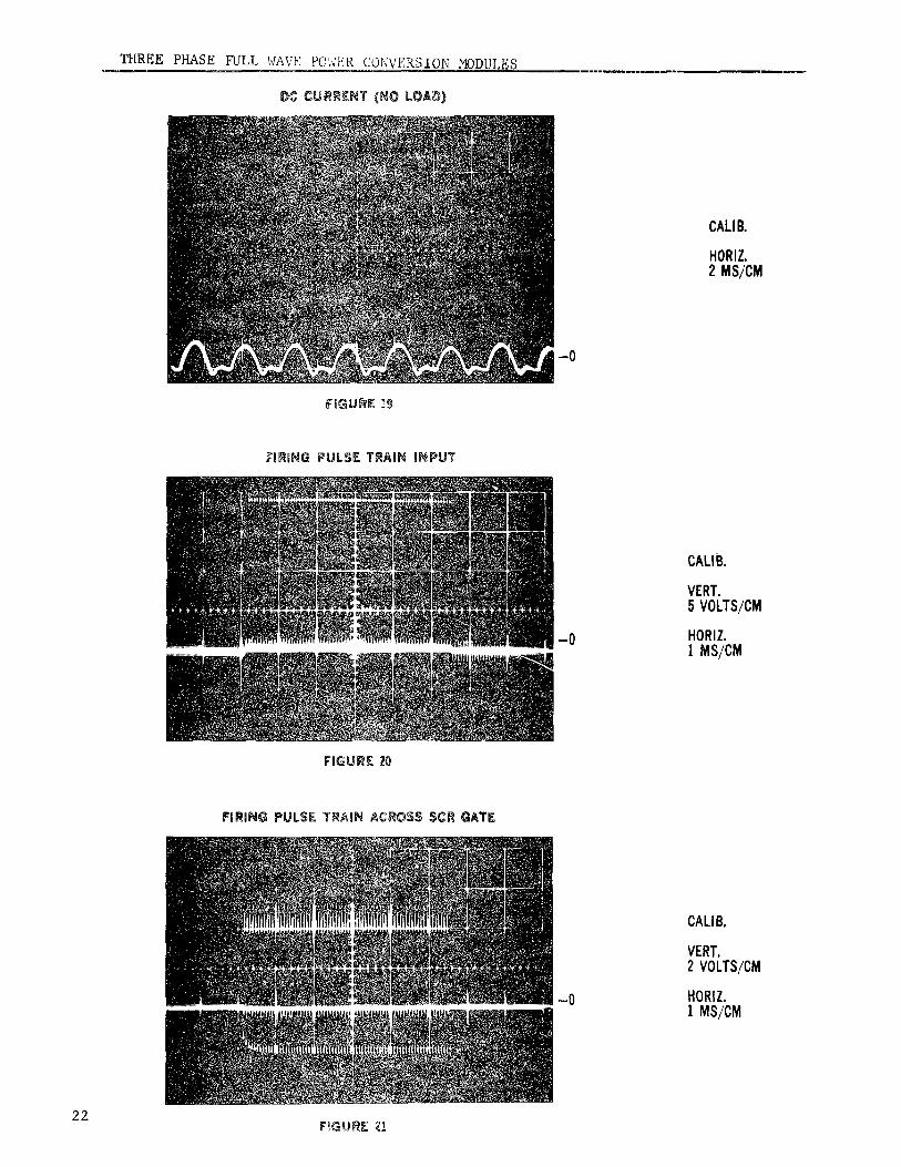
Missing output voltage and current pulses causing unbalanced
wave shape.
(a) Check for firing pulses at input to pulse transformer cards,
and at output of card to SCR's and compare with those givenin Figures 20 and 21 of the voltage wave shape checklist.
If no input is present, refer to the instruction book on
the Driver. If input is OK but no output is present, pulsetransformer card must be defective and should be replaced.
(b) Check SCR's to see if one of them is open or will not fire.Use the test circuit and follow the instructions under
"Checking SCR's" in this section.
Cannot obtain any output voltage or current
(a) Check for firing pulses at input to pulse transformer cards
and at output of cards to SCR's. If no input is present,refer to the instruction book on the Driver. Check the cable
connections between the Driver Signal Distribution Assembly
(if used) and the SCR Conversion Module. If inputs are OK
but no outputs are present, check 20 volt power supply to
pulse transformer card terminals A and B.
(b) Check for AC power at incoming terminals Ti, T2 and T3 ofthe SCR conversion Module.
THREE PHASE FULL WAVE POWER CONVERSION MODULES
One large output voltage and current pulse which cannot be
turned off and causes unbalanced wave shape
(a) Check for one SCR not being able to hold off forwardvoltage. Disconnect the cable from the SCR conversion
module and apply AC power. Connect oscilloscope acrosseach SCR, one at a time (T1-DC1, T2-DC1, T3-DC1, DC2-T1,
DC2-T2, DC2-T3) and check voltage wave shape across SCR
in the forward direction. Observe for SCR firing, or the
voltage being lower across one SCR in the forward directionthan the others. Also check SCR's with multimeter for
excessive leakage as explained under "Checking SCR's" in
this section. If a defective SCR is suspected, it shouldbe replaced and the module rechecked.
SCR Conversion Module trips out AC breaker when energized
(a) Check for shorted SCR (see instructions under "Checking
SCR's" in this section).
(b) Check for loose power connections or shorted bus bar. Usemultimeter selected to read ohms to check for shorts.
Paralleled SCR Conversion Modules and sharing current
Check for firing pulses into and out of Pulse Transformer Card,
for a defective SCR, or for presence of AC power at moduleterminals. See instructions under malfunctions on page 8.
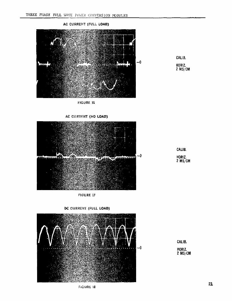
No current feedback signal or distorted current feedback signal
(a) Check the signal at test points A1 and A2 of the CurrentFeedback Card and compare with those given in Figures 18
and 19 of the voltage wave shape check list. If missing
or distorted, check output of current transformers at J1and J2, J3 and J4, and J5 and J6 on the Current Feedback
Card, and compare wave shapes with those given in Figures16 and 17.
If the current transformer outputs are all OK, but some of
the pulses are missing at card output terminals A1 and A2,the Current Feedback Card is defective and should be re-
placed. If the output of one of the current transformers
is missing or distorted, the current transformer may be
defective. Before removing the Conversion Module to
replace the suspected curremt transformer, try to check
the DC current with an oscilliscope across a shunt todetermine if a defective SCR is causing the trouble.
THREE PHASE FULL WAVE POWER CONVERSION MODUL_S
Thermoswitch open or trips often
If the thermoswitch opens, check for air flow obstruction orfor correct fan or blower rotation. If there is no air
obstruction and the rotation is correct, the thermoswitchmay be defective.
Erratic operation with motor load
(a) Check for correct phase sequence (see START-UP, page 7).
(b) Check for excessive dv/dt spikes across SCR's and wide
voltage notches in AC voltage wave. If a number of large
SCR drives are operating off the same AC supply, line
filtering may be necessary. Consult the General Electric
Company.
Checking SCR's
Disconnect the AC power and make sure the DC armature loopcontactor is open. Using a multimeter selected to read ohms
on the times - 1K scale, check the forward and reverse re-
sistance of each individual SCR cell. This is done by readingacross module terminals T1 and DC1, T2 and DCi, T3 and DC1,
DC2 and Ti, DC2 and T2, and DC2 and T3. (See SCR Conversion
Module elementary diagram.) Good or faulty SCR's will give the
following typical readings:
SCR
Description Fwd. Reading Reverse Reading.Good SCR 100K to Infinity 100K to InfinityShortedSCR Zero Zero
InoperativeSCR 1 to 2K 100K to Infinity
Open SCR 100K to Infinity 100K to Infinity
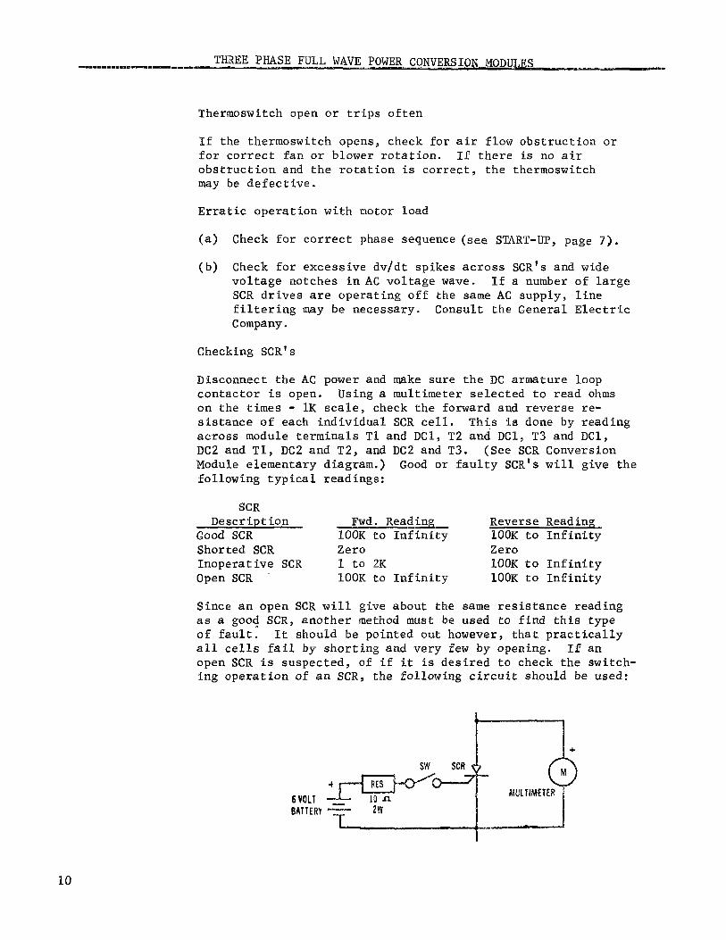
Since an open SCR will give about the same resistance reading
as a good SCR, another method must be used to find this typeof fault. It should be pointed out however, that practically
all cells fail by shorting and very few by opening. If an
open SCR is suspected, of if it is desired to check the switch-
ing operation of an SCR, the following circuit should be used:
+
SW SCR
- (>iV_ULTIMETER
BATTERY_ ZW
10
THREE PHASE FULL WAVE POWER CONVERSION MODULES
(continued)
The multimeter is selected to read ohms on the 1K scale, andis connected to read the forward resistance of the SCR. When
switch SW is closed, the forward resistance of a good SCR will
change from a high value (100K to infinity) to a low value
(1 to 10K). When the switch is opened, a good SCR will revert
to its high forward resistance or blocking state if the holding
current source (multimeter battery) is momentarily removed. A
faulty SCR will not switch, remaining in either an open or a
conducting state.
If any SCR's are suspected of being faulty from the above
resistance checks, the suspected SCR heat sink assembly shouldbe removed from the module.
After the SCR assembly has been disconnected, recheck the forwardand reverse resistances before replacing the SCR heat sink
assembly. This should be done before an SCR is definitely
classified as damaged or faulty, since a fault in another SCR
of another part of the circuitry can produce a faulty readingfrom a good SCR before it is disconnected from the circuit.
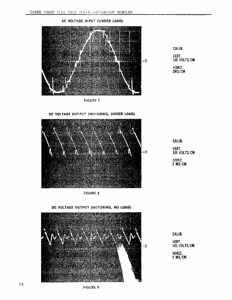
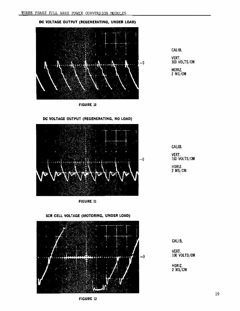
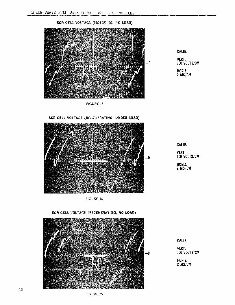
Voltage wave shape check list
VoltageWave Shape -- Figure Noo
AC voltageinput,underload 7
DC voltage output, motoring, under load 8
DC voltage output,motoring,no load 9
DC voltage output, regenerating, under load 10
DC voltage output, regenerating, no load 11
SCR cell voltage, motoring, under load 12
SCR cell voltage,motoring,no load 13
SCR cell voltage, regenerating, under load 14
SCR cell voltage, regenerating, no load 15AC current,fullload 16
AC current,no load 17
DC current,fullload 18
DC current,no load 19
Firingpulse traininput(to card) 20
Firing pulse trainacross SCR gate 21
Also refer to the DC and SCR voltage wave shapes given in "Principles
of Operation" section, as Figures 1 through 6. These diagrams do not
show firing notches but are otherwise s-imilar to actual readings.
REPAIR AND REPLACEMENT
To remove a heatsink or to replace an SCR, refer to the "Heatsink Repair and
Replacement" Instruction Book GEK-24991.
11

0° FIRING ANGLE
L31%_V_" _ LI
/\/\/\/\ AC
L1 L3 VOLTAGES(PHASE TO
NEUTRAL)
L2 L2
DC
VOLTAGE
(P1-P2)
j_ 120o>jCONDUCTION 1SCR
0 / "' VOLTAGE
/(ANODETO
CATHODE)
FIGURE 1
12
30° FIRING ANGLE
L3_ L]
AC
L1_ L3 VOLTAGES
Yi(PHASETONEUTRAL)
L2 I L25
DCVOLTAGE(P1-P2)
0
120 °
CONDUCTION,_ I SCR0 VOLTAGE
(ANODETOCATHODE)
FIGURE2
13
60° FIRING ANGLE
1 2 3
L3 A I ,_ I _ i,_1_ L1 AC
L1 \]/ ] \]/ !\1/Ij_ L3 VOLTAGES(PHASE TO
'I_ NEUTRAL)L2 L2
5 6 4 5
DcVOLTAGE
(PI*P2)
0
120° i
CONDUCTION)I 1 SCR
0 VOLTAGE
(ANODE TO
CATHODE)
FIGURE 3
1:+
90° FIRING ANGLE
L3,/ !l_ 'L1 AC
I_ VOLTAGES
L1 L3 (PH/[SETONEUTRAL)
L2, L26
/'t 12oo>[CONDUCTION
1 SCR0 VOLTAGE
(ANODETOCATHODE)
FIGURE4
15
120° FIRING ANGLE
L33 Ac3L1VOLTAGES(PHASETONEUTRAL)
L2 L2
0
VOLTAGE
(PI*P2)
\
120° _,m 1SCR
_o,_u_,o,tI vo_T^cE0 (ANODETO
CATHODE)
FIGURE5
16
150° FIRING ANGLE
L3 L1
ACVOLTAGES
L1 L3 (PHASETONEUTRAL)
0
DCVOLTAGE(P1-P2)
120°_,CONDUCTION_ 1 SCR
0 ,,, VOLTAGE(ANODETOCATHODE)
FIGURE 6
17
TIIREE PHASE FULL WAVE Pt)Wt,.F, {,O?;VERSION MODULESm .
AC VOLTAGEmNPUT(UNDERLOAD)
CALIB.
VERT.-0 100VOLTS/CM
HORiZ.2MS/CM
FIGURE 7
DC VOLTAGEOUTPUT(MOTORING,UNDERLOAD)
CALIB.
VERT.-0 100VOLTS/CM
HORIZ.2 MS/CM
FIGURE8
DC VOLTAGEOUTPUT(MOTORING,NO LOAD)
CALIB.
VERT.-0 100VOLTS/CM
HORIZ.2 MS/CM
18FtGU_[
THREE PHASE FULL WAVE POWER CONVERSION MODULES
DC VOLTAGEOUTPUT(REGENERATING,UNDERLOAD)
CALIB.
VERT.-0 100VOLTS/CM
HORIZ.2 MS/CM
FIGURE10
DC VOLTAGEOUTPUT(REGENERATING,NO LOAD)
CALIB.
VERT.-0 100VOLTS/CM
HORIZ.2 MS/CM
FIGURE11
SCRCELLVOLTAGE(MOTORING,UNDERLOAD)
CALIB.
VERT.-0 100VOLTS/CM
HORIZ.2 MS/CM
19FIGURE12
]:'HFLE]gPHASE FULL WA\'I_ ?U'47,_'' i,_)_:Vi'-_{S1ONMODULES
$CR CELLVOLTAGe:([,_!O'_OR]l'4_,NO LOAD)
CALIB.
VERT.-0 100VOLTS/CM
HORIZ.2 MS/CM
FiGUrE 13
$CR CELLVOLTAGE(REGEN[RATtNG,UNDERLOAD)
CALIB.
VERT.-0 100VOLTS/CM
HORIZ.2 MS/CM
FIGURE14
SCRCELLVOLTAGE(REGENERATING,NO LOAD)
CALIB.
VERT.-0 100VOLTS/CM
HORIZ.2 MS/CM
20
THREE PHASE FULL WAVE POWER CONVERSION MODULESIT _ T I
AC CURRENT (FULL LOAD)
CALIB.
-0 HORIZ.2 MS/eM
FmGURE1G
AC CUR_F.NT (NO LOAD)
CALIB.
-0 HORIZ.2 MS/CM
FIGUR[ 17
DC CORA[NY (FULL LOAD)
CALIB.
-0 HORIZ.2 MS/CM
21F_UR[ 18
THREE PHASE FULL WAVE' POWER CONVERSION MODUL_ES
DC CURRENT(NO LOAD)
CALIB.
HORIZ.2MS/CM
-0
FIGURE.[9
FIRINGPULSET_AgN INPUT
CALIB.
VERT.5 VOLTS/CM
-0 HORIZ.1MS/CM
FIGURE20
FIRINGPULSETRAmNACROSS$CRGATE
CALIB.
VERT.2 VOLTS/CM
-0 HORIZ.
1 MS/CM22
F_GU_E21

GENERAL ELI'CI'RIC COMPANY - DIRECT CURRENT MOTOR & GENERATOR PROr)UCTS DI-'PARTMENT
ERIF, PENNSYLVANIA 16531
GENERAL_ ELECTRIC '";?':