Embed Size (px)
Citation preview
GENERAL DESCRIPTION OF MODEL 9602-GSM
Version 1.0
December 5th, 2011
TN2011-041-V1.0
Copyright © 2011 by NAL Research Corporation 9300 West Courthouse Road
Manassas, Virginia 20110 USA
Phone: 703-392-1136 x203
E-mail: [email protected]
NAL Research Corporation (TN2011-041-V1.0) 2
LEGAL DISCLAIMER AND CONDITIONS OF USE
This document contains information for the Iridium 9602-GSM Tracker and accompanying accessories
(“Product”) is provided “as is.” Reasonable effort has been made to make the information in this document
reliable and consistent with specifications, test measurements and other information. However, NAL
Research Corporation and its affiliated companies, directors, officers, employees, agents, trustees or
consultants (“NAL Research”) assume no responsibility for any typographical, technical, content or other
inaccuracies in this document. NAL Research reserves the right in its sole discretion and without notice to
you to change Product specifications and materials and/or revise this document or withdraw it at any time.
User assumes the full risk of using the Product specifications and any other information provided.
NAL Research makes no representations, guarantees, conditions or warranties, either express or
implied, including without limitation, any implied representations, guarantees, conditions or warranties of
merchantability and fitness for a particular purpose, non-infringement, satisfactory quality, non-interference,
accuracy of informational content, or arising from a course of dealing, law, usage, or trade practice, use, or
related to the performance or nonperformance of any products, accessories, facilities or services or
information except as expressly stated in this guide and/or the Product and/or satellite service
documentation. Any other standards of performance, guarantees, conditions and warranties are hereby
expressly excluded and disclaimed to the fullest extent permitted by the law. This disclaimer and exclusion
shall apply even if the express limited warranty contained in this guide or such documentation fails of its
essential purpose.
In no event shall NAL Research be liable, whether in contract or tort or any other legal theory, including
without limitation strict liability, gross negligence or negligence, for any damages in excess of the purchase
price of the Product, including any direct, indirect, incidental, special or consequential damages of any kind,
or loss of revenue or profits, loss of business, loss of privacy, loss of use, loss of time or inconvenience, loss
of information or data, software or applications or other financial loss caused by the Product (including
hardware, software and/or firmware) and/or the Iridium satellite services, or arising out of or in connection
with the ability or inability to use the Product (including hardware, software and/or firmware) and/or the
Iridium satellite services to the fullest extent these damages may be disclaimed by law and whether advised
of the possibilities of such damages. NAL Research is not liable for any claim made by a third party or made
by you for a third party.
NAL Research Corporation (TN2011-041-V1.0) 3
TABLE OF CONTENTS
TABLE OF CONTENTS ....................................................................................................... 3
GLOSSARY ...................................................................................................................... 4
1.0 PURPOSE ................................................................................................................... 5
2.0 GENERAL SPECIFICATIONS .......................................................................................... 6
3.0 USER INTERFACES ..................................................................................................... 8
4.0 IMPORTANT FEATURES ................................................................................................ 14
5.0 CONFIGURING THE 9602-GSM ..................................................................................... 16
6.0 TYPICAL POWER USAGE PROFILE ................................................................................. 37
7.0 TECHNICAL SUPPORT ................................................................................................... 40
APPENDIX A: STANDARDS OF COMPLIANCE ........................................................................ 41
APPENDIX B: EXPORT COMPLIANCE INFORMATION .............................................................. 42
APPENDIX C: DESCRIPTION OF THE IRIDIUM NETWORK ....................................................... 43
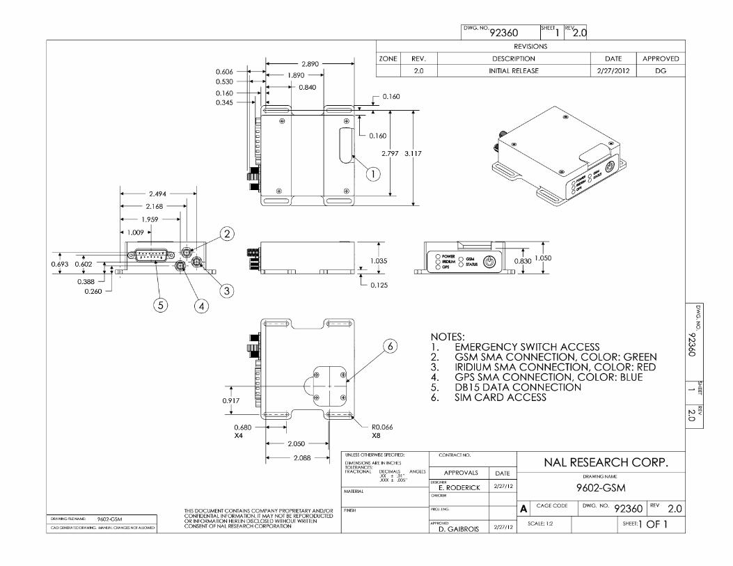
MECHANICAL DRAWING .................................................................................................... 49
NAL Research Corporation (TN2011-041-V1.0) 4
GLOSSARY
AES Advanced Encryption Standard
BIS Bureau of Industry and Security
CEP Circular Error Probable
DGPS Differential Global Positioning System
DoD EMSS DoD Enhanced Mobile Satellite Services
DTE Data Terminal Equipment
DSN Defense Switch Network
EAR Export Administration Regulations
EMI Electromagnetic Interference
FDMA Frequency Division Multiple Access
GND Ground
GPS Global Positioning System
GUI Graphical User Interface
ID Static Identifier
ISU Iridium Subscriber Units
LED Light Emitting Diode
LiIon Lithium Ion
LNA Low Noise Amplifier
LP Low Power
NOC Network Operation Center
OFAC Office of Foreign Asset Controls
PMS PECOS Message Structure
PSTN Public Switch Telephone Network
PWR Power
RHCP Right Hand Circular Polarization
RUDICS Router-Based Unrestricted Digital Internetworking Connectivity Solution
SBAS Satellite Based Augmentation System
SBD Short Burst Data
SMA Sub-Miniature Version A
SMS Short Message Service
TDD Time Division Duplex
TDMA Time Division Multiple Access
VSWR Voltage Standing Wave Ratio
NAL Research Corporation (TN2011-041-V1.0) 5
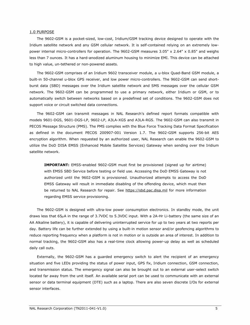
1.0 PURPOSE
The 9602-GSM is a pocket-sized, low-cost, Iridium/GSM tracking device designed to operate with the
Iridium satellite network and any GSM cellular network. It is self-contained relying on an extremely low-
power internal micro-controllers for operation. The 9602-GSM measures 3.05" x 2.64" x 0.85" and weighs
less than 7 ounces. It has a hard-anodized aluminum housing to minimize EMI. This device can be attached
to high value, un-tethered or non-powered assets.
The 9602-GSM comprises of an Iridium 9602 transceiver module, a u-blox Quad-Band GSM module, a
built-in 50-channel u-blox GPS receiver, and low power micro-controllers. The 9602-GSM can send short-
burst data (SBD) messages over the Iridium satellite network and SMS messages over the cellular GSM
network. The 9602-GSM can be programmed to use a primary network, either Iridium or GSM, or to
automatically switch between networks based on a predefined set of conditions. The 9602-GSM does not
support voice or circuit switched data connections.
The 9602-GSM can transmit messages in NAL Research’s defined report formats compatible with
models 9601-DGS, 9601-DGS-LP, 9602-LP, A3LA-XGS and A3LA-RGS. The 9602-GSM can also transmit in
PECOS Message Structure (PMS). The PMS complies with the Blue Force Tracking Data Format Specification
as defined in the document PECOS 200907-001 Version 1.7. The 9602-GSM supports 256-bit AES
encryption algorithm. When requested by an authorized user, NAL Research can enable the 9602-GSM to
utilize the DoD DISA EMSS (Enhanced Mobile Satellite Services) Gateway when sending over the Iridium
satellite network.
IMPORTANT: EMSS-enabled 9602-GSM must first be provisioned (signed up for airtime)
with EMSS SBD Service before testing or field use. Accessing the DoD EMSS Gateway is not
authorized until the 9602-GSM is provisioned. Unauthorized attempts to access the DoD
EMSS Gateway will result in immediate disabling of the offending device, which must then
be returned to NAL Research for repair. See https://sbd.pac.disa.mil for more information
regarding EMSS service provisioning.
The 9602-GSM is designed with ultra-low power consumption electronics. In standby mode, the unit
draws less that 65A in the range of 3.7VDC to 5.3VDC input. With a 2A-Hr Li-battery (the same size of an
AA Alkaline battery), it is capable of delivering uninterrupted service for up to two years at two reports per
day. Battery life can be further extended by using a built-in motion sensor and/or geofencing algorithms to
reduce reporting frequency when a platform is not in motion or is outside an area of interest. In addition to
normal tracking, the 9602-GSM also has a real-time clock allowing power-up delay as well as scheduled
daily call outs.
Externally, the 9602-GSM has a guarded emergency switch to alert the recipient of an emergency
situation and five LEDs providing the status of power input, GPS fix, Iridium connection, GSM connection,
and transmission status. The emergency signal can also be brought out to an external user-select switch
located far away from the unit itself. An available serial port can be used to communicate with an external
sensor or data terminal equipment (DTE) such as a laptop. There are also seven discrete I/Os for external
sensor interfaces.
NAL Research Corporation (TN2011-041-V1.0) 6
2.0 GENERAL SPECIFICATIONS
2.1 Mechanical Specifications
Dimensions: 3.05” L x 2.64” W x 0.85” D (77 mm x 67 mm x 22 mm)
Weight: 6.4 oz. (181 g)
Enclosure: Hard anodized aluminum/EMI shielding
Multi-Interface Connector: 15-Pin D-Sub
Antenna Interfaces: Color-coded connectors
Iridium Antenna: SMA female (Red)
GSM Antenna: SMA female (Green)
GPS Antenna: SMA female (Blue)
OFF/ON Switch: Push button
Emergency Switch: Guarded button and/or external via multi-interface connector
GSM SIM Chip Reader: Located on bottom of the 9602-GSM
Status LED Displays: Power, GPS, Iridium, GSM and message sent status
2.2 Iridium RF Specifications
Operating Frequency: 1616 to 1626.5 MHz
Duplexing Method: TDD
Input/Output Impedance: 50
Multiplexing Method: TDMA/FDMA
2.3 Iridium Radio Characteristics
Average Power during a Transmit Slot (Max): 1.6W
Receiver Sensitivity at 50 (Typical): –117 dBm
Maximum Cable Loss Permitted: 2dB
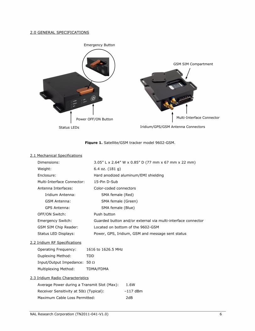
Figure 1. Satellite/GSM tracker model 9602-GSM.
Emergency Button
Power OFF/ON Button
Status LEDs
Multi-Interface Connector
Iridium/GPS/GSM Antenna Connectors
GSM SIM Compartment
NAL Research Corporation (TN2011-041-V1.0) 7
Link Margin – Downlink: 13dB
Link Margin – Uplink: 7dB
2.4 GSM RF Specifications
Receiver Type: u-blox LEON-G100, Quad-Band 850/900/1800/1900 MHz
Sensitivity: 110 dBm @850/900 MHz, 109 dBm @1800/1900 MHz
2.5 GSM Radio Characteristics
Power Class: Class 4 (33 dBm) for GSM/EGSM (850/900 MHz)
Class 1 (30 dBm) for DCS/PCS (1800/1900 MHz)
Receive Sensitivity: –110 dBm for GSM/EGSM (850/900 MHz)
–109 dBm for DCS/PCS (1800/1900 MHz)
2.6 GPS Receiver performance data
Type of GPS Receiver: NEO-6Q from u-blox AG
Receiver Type: L1 frequency
C/A code
50-Channel
SBAS: WAAS, EGNOS, MSAS, GAGAN
Update Rate: 5Hz
Accuracy: Position 8.2 feet (2.5 meters) CEP
Position DGPS/SBAS 6.6 feet (2.0 meters) CEP
Acquisition (typical): Hot starts 1 second
Aided starts 1 second
Warm starts 28 seconds
Cold starts 28 seconds
Sensitivity: Tracking 160 dBm
Reacquisition 160 dBm
Cold starts 147 dBm
Operational Limits: COCOM restrictions apply
Altitude 164,000 feet (50,000 meters)
Velocity 1,640 feet/sec (500 m/sec)
One of the limits may be exceeded but not both
As long as power is provided to the 9602-GSM, the GPS receiver will store ephemeris data in its
memory before powering down (sleep between reports). The ephemeris data are valid up to two hours and
can be used in future startup to improve time-to-first-fix.
2.7 Electrical Specifications
Input Voltage Range: +4.0V to +5.3V or +6.0V to +32V
Main Input Voltage Ripple: < 40mV peak-to-peak
Transmit Current (Average): 200mA @ 5V
Transmit Current (Peak): 1.5A @ 5V for Iridium; 2.5A @ 5V for GSM
Receive Current (Average): 45mA @ 5V
NAL Research Corporation (TN2011-041-V1.0) 8
Receive Current (Peak): 195mA @ 5V
Message Transfer Power (Average): <= 1.1W @ 5V
Current in Between Reports: Less than 65A @ 5V
Power Input Type: DC power or LiIon battery
NOTE: The DC power requirement was measured at the 9602-GSM multi-interface
connector and not at the DC power supply. Users must take into account voltage drop
across the power supply cable to ensure adequate current provided to the 9602-GSM during
transmission. If input voltage does not stay above 4.0V during surge or high current
demand, the 9602-GSM will reset itself.
NOTE: The average current drawn during transmission may vary depending on the field-
of-view between the 9602-GSM antenna and the Iridium satellite, the type of Iridium
antenna used and cable loss, and GSM signal strength.
2.8 Environmental Specifications
Operating Temperature Range: –22oF to +158oF (–30oC to +70oC)
Operating Humidity Range: ≤ 75% RH
Storage Temperature Range: –40oF to +185oF (–40oC to +85oC)
Storage Humidity Range: ≤ 93% RH
2.9 Data I/O Specifications
Short-Burst Data Mobile-Originated: 340 bytes per message (Iridium)
Short-Burst Data Mobile-Terminated: 270 bytes per message (Iridium)
Short Message Service (SMS): 140 bytes or 160 seven-bit characters per message (GSM)
Hardware Interface: 3-Wire RS232
Software Interface: AT commands
2.10 Related Hardware
Iridium/GSM/GPS Antenna: SAF7352-IGG
Iridium/GPS Antenna: SAF4070-IG and SAF7352-IG
Iridium Antenna: SYN7391 series, SAF2040 series, SAF5340 series and SAF5350 series
GPS Antenna: SAF5270-G
AC Power Adapter: LA-3098 (100240VAC, 4760Hz input)
Car Adapter: LA-7021 (12VDC car battery input)
Power Cable: HRC-24-12, HRC-24-12A
3.0 USER INTERFACES
3.1 Power Button
The 9602-GSM has a single power ON/OFF button. With the correct internal voltage setting either at
4.0V 5.3V or 6.0V 32.0V (see Section 3.3), the 9602-GSM is set to power up automatically when DC
power is first applied to either pin 1 or pin 9 on the multi-interface connector. It can be turned off/on again
by momentarily holding down the power button and release. If the device is sleeping in between reporting
cycles, pressing the power button will turn the 9602-GSM on for 10 seconds. During this time, user can
NAL Research Corporation (TN2011-041-V1.0) 9
take the device out of Tracking mode into Command mode by entering a sequence three pluses, “+++”.
The 9602-GSM can now operate as a standard modem ready to accept AT commands. If “+++” is not
entered within 10 seconds, the 9602-GSM goes back to “sleep” (see Section 4.2). The AT command ^IPS,
‘Initial Power State’, is used to set whether the 9602-GSM will begin operation when power is first applied
or if the power button must be pressed to activate the device.
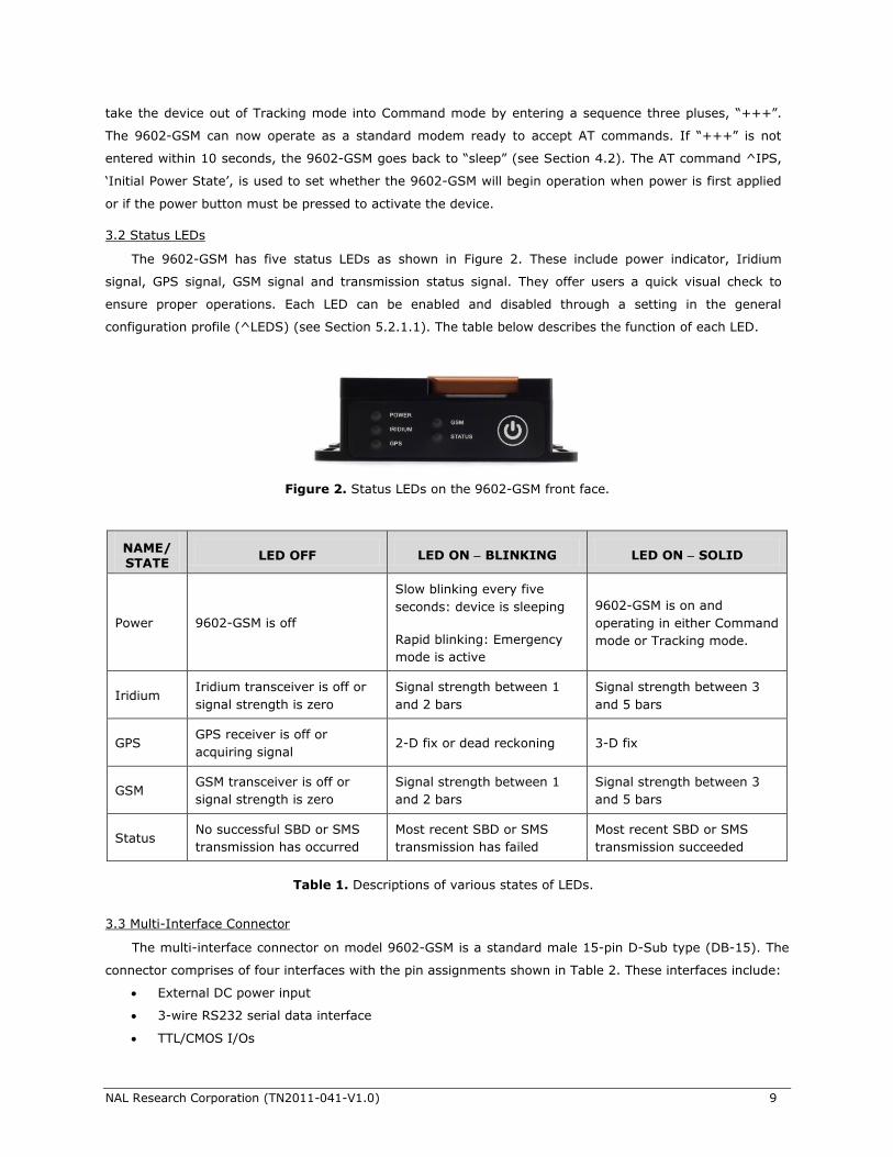
3.2 Status LEDs
The 9602-GSM has five status LEDs as shown in Figure 2. These include power indicator, Iridium
signal, GPS signal, GSM signal and transmission status signal. They offer users a quick visual check to
ensure proper operations. Each LED can be enabled and disabled through a setting in the general
configuration profile (^LEDS) (see Section 5.2.1.1). The table below describes the function of each LED.
Table 1. Descriptions of various states of LEDs.
3.3 Multi-Interface Connector
The multi-interface connector on model 9602-GSM is a standard male 15-pin D-Sub type (DB-15). The
connector comprises of four interfaces with the pin assignments shown in Table 2. These interfaces include:
External DC power input
3-wire RS232 serial data interface
TTL/CMOS I/Os
NAME/ STATE
LED OFF LED ON BLINKING LED ON SOLID
Power 9602-GSM is off
Slow blinking every five
seconds: device is sleeping
Rapid blinking: Emergency
mode is active
9602-GSM is on and
operating in either Command
mode or Tracking mode.
Iridium Iridium transceiver is off or
signal strength is zero
Signal strength between 1
and 2 bars
Signal strength between 3
and 5 bars
GPS GPS receiver is off or
acquiring signal 2-D fix or dead reckoning 3-D fix
GSM GSM transceiver is off or
signal strength is zero
Signal strength between 1
and 2 bars
Signal strength between 3
and 5 bars
Status No successful SBD or SMS
transmission has occurred
Most recent SBD or SMS
transmission has failed
Most recent SBD or SMS
transmission succeeded
Figure 2. Status LEDs on the 9602-GSM front face.
NAL Research Corporation (TN2011-041-V1.0) 10
Reserved RS232 serial data interface
Table 2. Pin assignments for the 9602-GSM multi-interface connector.
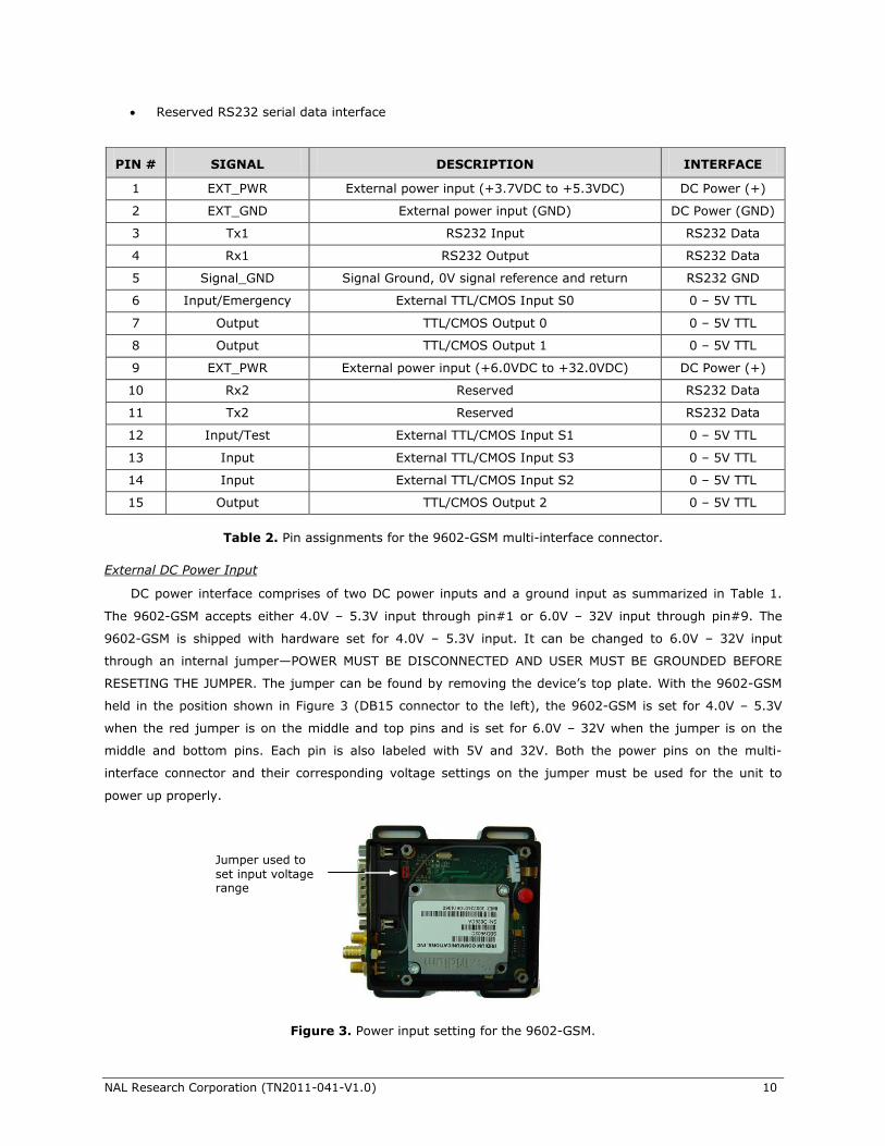
External DC Power Input
DC power interface comprises of two DC power inputs and a ground input as summarized in Table 1.
The 9602-GSM accepts either 4.0V – 5.3V input through pin#1 or 6.0V – 32V input through pin#9. The
9602-GSM is shipped with hardware set for 4.0V – 5.3V input. It can be changed to 6.0V – 32V input
through an internal jumper—POWER MUST BE DISCONNECTED AND USER MUST BE GROUNDED BEFORE
RESETING THE JUMPER. The jumper can be found by removing the device’s top plate. With the 9602-GSM
held in the position shown in Figure 3 (DB15 connector to the left), the 9602-GSM is set for 4.0V – 5.3V
when the red jumper is on the middle and top pins and is set for 6.0V – 32V when the jumper is on the
middle and bottom pins. Each pin is also labeled with 5V and 32V. Both the power pins on the multi-
interface connector and their corresponding voltage settings on the jumper must be used for the unit to
power up properly.
PIN # SIGNAL DESCRIPTION INTERFACE
1 EXT_PWR External power input (+3.7VDC to +5.3VDC) DC Power (+)
2 EXT_GND External power input (GND) DC Power (GND)
3 Tx1 RS232 Input RS232 Data
4 Rx1 RS232 Output RS232 Data
5 Signal_GND Signal Ground, 0V signal reference and return RS232 GND
6 Input/Emergency External TTL/CMOS Input S0 0 – 5V TTL
7 Output TTL/CMOS Output 0 0 – 5V TTL
8 Output TTL/CMOS Output 1 0 – 5V TTL
9 EXT_PWR External power input (+6.0VDC to +32.0VDC) DC Power (+)
10 Rx2 Reserved RS232 Data
11 Tx2 Reserved RS232 Data
12 Input/Test External TTL/CMOS Input S1 0 – 5V TTL
13 Input External TTL/CMOS Input S3 0 – 5V TTL
14 Input External TTL/CMOS Input S2 0 – 5V TTL
15 Output TTL/CMOS Output 2 0 – 5V TTL
Figure 3. Power input setting for the 9602-GSM.
Jumper used to
set input voltage range
NAL Research Corporation (TN2011-041-V1.0) 11
NOTE: User MUST remember not to apply voltage higher than 5.3V on pin 1 (or accidently
swap voltage between pins 1 and 9). The 9602-GSM will be damaged beyond repair with
warranty voided if this were to occur.
IMPORTANT: User can remove the 9602-GSM’s top plate to set the jumper but not for
repair or services. The warranty is voided if the 9602-GSM is disassembled for any reason
other than to set the jumper.
Cables used to supply power to the 9602-GSM should be kept as short as possible to prevent significant
voltage drop, which can cause the 9602-GSM to malfunction during an SBD/SMS session. Power reset by the
9602-GSM during an SBD/SMS transmission is an indicative of the DC power source unable to sustain
voltage above 4.0V or above 6V at peak current demand. Plots of DC power requirement for the 9602-GSM
are found in Section 6.
RS232 Serial Data Interface
The 9602-GSM supports 3-wire serial interface to a host DTE through the multi-interface connector. The
serial connection comprises of a transmit (Tx) line on pin 3, a receive (Rx) line on pin 4 and a signal GND on
pin 5 as described in Table 2. The 9602-GSM does not support auto-baud and the default baud rate is
factory set at 19.2kbits/sec. The baud rate can be reconfigured with the +IPR command ranging from
4.8kbits/sec to 115.2kbits/sec.
The serial port allows a connected DTE to configure the 9602-GSM using NAL Research’s defined AT
commands and any terminal emulator software. These AT commands can be found in the manual “AT
Commands for Model 9602-GSM” TN2011-042-V1.0. Instead of trying to memorize various functions of AT
commands, NAL Research recommends the use of SatTerm graphical user interface (GUI) software to
configure the 9602-GSM.
TTL/CMOS Inputs/Outputs
The 9602-GSM has four TTL/CMOS inputs and three TTL/CMOS outputs. All I/Os are brought out to
the multi-interface connector. The four CMOS/TTL inputs, denoted as S0 through S3, have internal pull
ups which allow the inputs to float as high. The inputs can be configured as emergency, test, or general
input with a trigger on a rising and/or falling edge. The trigger activates the special functionality of the
input type. Emergency configured inputs enable the Emergency tracking mode when triggered. Test
configured inputs enable the Test tracking mode. General configured inputs queue the transmission of an
input report (see Appendix C in “AT Commands for Model 9602-GSM” TN2011-042-V1.0). Regardless of
the type or trigger configuration, the value of the input will be included in any Version 5 GPS report or
higher. By default, S0 is configured as an emergency input triggered by a falling edge and S1 is
configured as a test input triggered by a falling edge. S0 is shared with the on board emergency button.
This means both the guarded emergency button on the 9602-GSM and S0 can be used to activate
Emergency tracking.
The AT command ^PR controls input value reporting. When ^PR is enabled and a pin changes state,
an unsolicited response, ^PV, will be sent on the serial port indicating the values of the input pins. Setting
the outputs is controlled by the AT command ^Pn. Outputs can also be set by remote update. For detailed
information regarding I/Os, users are referred to the manual “AT Commands for Model 9602-GSM”.
NAL Research Corporation (TN2011-041-V1.0) 12
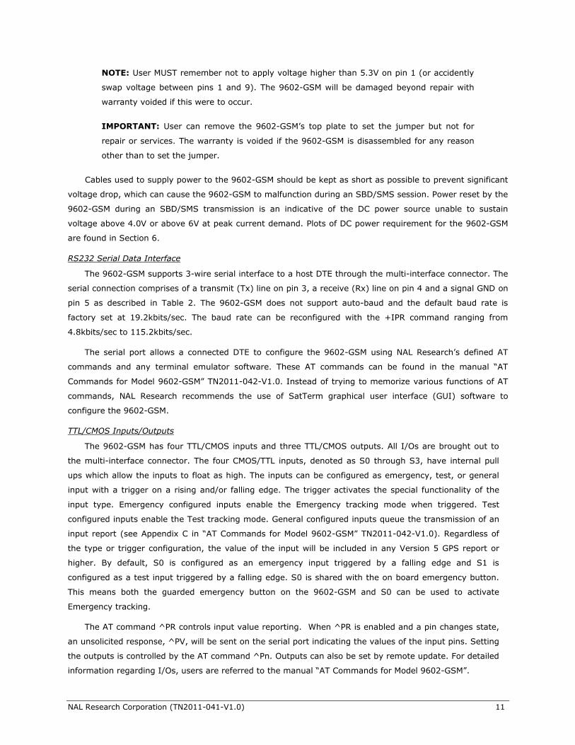
3.4 SIM Card Holder for GSM Network
The 9602-GSM contains an integrated SIM reader. The device uses a GSM SIM chip for operation
when using the cellular network including AT&T and T-Mobile. The SIM chip is inserted into the opening
located on the bottom of the modem. A plastic locking mechanism is used hold the SIM in place. Slide the
SIM chip reader’s plastic bracket in the direction indicated by the arrow and lift up the bracket. Place the
SIM chip (facing down) into the SIM bracket as shown in Figure 4. There is a small cut-off on one of the
corners of the SIM chip. Make sure that the cut-off is pointing upward which should align the SIM chip
with the SIM chip reader. Lower the bracket and lock the SIM bracket by sliding in the reverse direction.
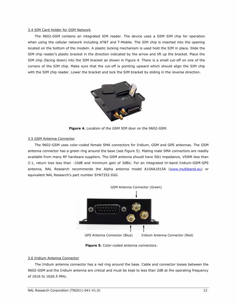
3.5 GSM Antenna Connector
The 9602-GSM uses color-coded female SMA connectors for Iridium, GSM and GPS antennas. The GSM
antenna connector has a green ring around the base (see Figure 5). Mating male SMA connectors are readily
available from many RF hardware suppliers. The GSM antenna should have 50 impedance, VSWR less than
2:1, return loss less than 10dB and minimum gain of 3dBic. For an integrated tri-band Iridium-GSM-GPS
antenna, NAL Research recommends the Alpha antenna model A10AA1815A (www.multiband.eu) or
equivalent NAL Research’s part number SYN7352-IGG.
3.6 Iridium Antenna Connector
The Iridium antenna connector has a red ring around the base. Cable and connector losses between the
9602-GSM and the Iridium antenna are critical and must be kept to less than 2dB at the operating frequency
of 1616 to 1626.5 MHz.
Figure 4. Location of the GSM SIM door on the 9602-GSM.
Figure 5. Color-coded antenna connectors.
Iridium Antenna Connector (Red) GPS Antenna Connector (Blue)
GSM Antenna Connector (Green)
NAL Research Corporation (TN2011-041-V1.0) 13
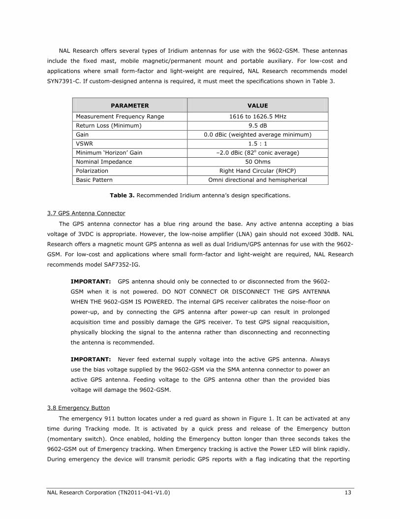
NAL Research offers several types of Iridium antennas for use with the 9602-GSM. These antennas
include the fixed mast, mobile magnetic/permanent mount and portable auxiliary. For low-cost and
applications where small form-factor and light-weight are required, NAL Research recommends model
SYN7391-C. If custom-designed antenna is required, it must meet the specifications shown in Table 3.
Table 3. Recommended Iridium antenna’s design specifications.
3.7 GPS Antenna Connector
The GPS antenna connector has a blue ring around the base. Any active antenna accepting a bias
voltage of 3VDC is appropriate. However, the low-noise amplifier (LNA) gain should not exceed 30dB. NAL
Research offers a magnetic mount GPS antenna as well as dual Iridium/GPS antennas for use with the 9602-
GSM. For low-cost and applications where small form-factor and light-weight are required, NAL Research
recommends model SAF7352-IG.
IMPORTANT: GPS antenna should only be connected to or disconnected from the 9602-
GSM when it is not powered. DO NOT CONNECT OR DISCONNECT THE GPS ANTENNA
WHEN THE 9602-GSM IS POWERED. The internal GPS receiver calibrates the noise-floor on
power-up, and by connecting the GPS antenna after power-up can result in prolonged
acquisition time and possibly damage the GPS receiver. To test GPS signal reacquisition,
physically blocking the signal to the antenna rather than disconnecting and reconnecting
the antenna is recommended.
IMPORTANT: Never feed external supply voltage into the active GPS antenna. Always
use the bias voltage supplied by the 9602-GSM via the SMA antenna connector to power an
active GPS antenna. Feeding voltage to the GPS antenna other than the provided bias
voltage will damage the 9602-GSM.
3.8 Emergency Button
The emergency 911 button locates under a red guard as shown in Figure 1. It can be activated at any
time during Tracking mode. It is activated by a quick press and release of the Emergency button
(momentary switch). Once enabled, holding the Emergency button longer than three seconds takes the
9602-GSM out of Emergency tracking. When Emergency tracking is active the Power LED will blink rapidly.
During emergency the device will transmit periodic GPS reports with a flag indicating that the reporting
PARAMETER VALUE
Measurement Frequency Range 1616 to 1626.5 MHz
Return Loss (Minimum) 9.5 dB
Gain 0.0 dBic (weighted average minimum)
VSWR 1.5 : 1
Minimum ‘Horizon’ Gain –2.0 dBic (82o conic average)
Nominal Impedance 50 Ohms
Polarization Right Hand Circular (RHCP)
Basic Pattern Omni directional and hemispherical
NAL Research Corporation (TN2011-041-V1.0) 14
device is in active Emergency mode. The Emergency trigger can further be customized using the I/Os
configuration screen (see Section 5.2.1.1).
4.0 IMPORTANT FEATURES
4.1 Networks
The 9602-GSM uses Iridium and any GSM cellular network to send its location reports. The device can
be configured for either Iridium or GSM, or to automatically switch between the two networks based on
network availability.
NOTE: To use GSM, the 9602-GSM must first be provided with an active Subscriber
Identity Module (SIM) card from a GSM cellular provider. Pre-paid SIM cards are
acceptable. Example of GSM cellular providers in the United States are AT&T and T-Mobile.
4.2 Modes of Operation
The 9602-GSM is always in one of two modes: (1) Command mode, or (2) Tracking mode. It can be
configured to power up in one of these modes. The factory-set power-up mode is Command mode, which
can be changed with the ‘Start-Up Mode’ configuration (Section 5.2.1.1).
4.2.1 Command Mode
When in Command mode, the 9602-GSM accepts AT commands through a 3-wire RS-232 serial
interface from a connected DTE. The command set is detailed in the document “AT Commands for Model
9602-GSM”. The commands can be used to configure the 9602-GSM operating parameters, to allow the
9602-GSM be operated as a modem, and to query the GPS receiver. Command mode can be switched to
Tracking mode by AT command ^TRK. To switch back, the escape sequence ‘+++’ is used.
4.2.2 Tracking Mode
When in Tracking mode, the 9602-GSM automatically transmits GPS reports using parameters contained
in a tracking profile (see Section 5.2.1.2). It can be configured to send at an interval ranging from
continuous (as fast as the transmitter can handle) to once every 7 days. The 9602-GSM can also be
configured to operate with the GPS receiver and Iridium/GSM transmitter ON at all times or it can operate in
a low-power mode whereby the device powers down and sleeps between reports. When operates in low-
power mode, the device consumes less than 65A of current during sleep.
There are a number of options that impact Tracking mode, but the most commonly used are “Time
Between Reports” (AT^TBR), “Time to Keep Trying” (AT^TTKT), and “Callable” (AT^CALn). These settings
have impact on the reporting interval and power consumption. The motion detection and geofencing
features can also be implemented to further tailor Tracking mode to a specific application.
While in Tracking mode, the 9602-GSM can load tracking profiles dynamically. By default there are three
tracking profiles set aside for Normal tracking, Test tracking, and Emergency tracking. Typically, when
Tracking mode starts, the tracking profile for Normal tracking is loaded, specified by the "Tracking Profile
Normal" (AT^TPN) setting. When the Test pin or Emergency pin is triggered, Tracking mode will switch to
using the tracking profile for Test tracking, specified by the "Tracking Profile Test" (AT^TPT) setting, or the
tracking profile for Emergency Tracking, specified by the "Tracking Profile Emergency" (AT^TPE) setting,
respectively. This allows the user to configure the 9602-GSM to operate differently when there is an external
NAL Research Corporation (TN2011-041-V1.0) 15
stimulus. Tracking mode will also load a different tracking profile if Geofences are enabled and the 9602-
GSM enters or exits a geofence. Priorities are assigned to the different stimuli and the 9602-GSM will only
switch to the associated tracking profile if it has a higher priority. Emergency tracking has the highest
priority, Test tracking is the second highest, Geofence is the third highest, and Normal tracking is the
default.
The 9602-GSM can transmit messages in NAL Research's defined report formats and can also transmit
messages according to the PECOS Message Structure (PMS) compatible with the US NORTHCOM MMC
server. The PMS complies with the Blue Force Tracking Data Format Specification as defined in the
document PECOS 200907-001 Version 1.7.
4.3 Call-Outs and Power-Up Delay
Using an onboard real-time clock, the 9602-GSM can be configured to send daily call-out reports at
specified UTC times. These call-out reports are in addition to tracking reports sent at a pre-defined tracking
interval and they are indistinguishable from each other. Call-outs can be used as a heartbeat to determine if
the device is still operational (see Section 5.2.3).
In addition, using the onboard real-time clock, the 9602-GSM can be configured for a power-up delay. A
power-up delay is set for a specific UTC time and date up to 45 days in the future. When a delay is set and
tracking is started, the device will remain in its low-power sleep mode until the configured date and time
upon which the device will power on automatically and begin its Tracking mode. This is useful for conserving
battery power while the tracker is in transit to a destination (see Section 5.2.1.3).
4.4 Geofencing
The 9602-GSM can utilize location information from its GPS receiver to determine whether it has
entered or exited the bounds of preconfigured geofences. A geofence is a set of connected latitude and
longitude coordinates that defines a region or zone of interest. A geofence is defined by a minimum of 3
coordinates and a maximum of 50. Multiple geofences can be configured, each with a unique set of tracking
parameters that will cause the 9602-GSM to change its tracking behavior while in a specific geofence. Each
geofence can also be configured to send a report upon entering and exiting the defined geofence region. In
addition, geofences can be configured to turn off all transmitting radio links (Iridium and GSM) for regions
that require radio silence.
4.5 Motion Detection
The 9602-GSM has a built-in sensor that can reliably detect motion. It is truly an omni-directional
movement sensor and will function regardless of how the 9602-GSM is mounted or aligned. It is sensitive to
both tilt (static acceleration) and vibration (dynamic acceleration). The sensor produces a series of TTL level
logic or pulse train. The signal level is fed directly into the 9602-GSM’s micro-controller to “wake up” the
9602-GSM out of low-power mode when activity is sensed and to transmit location report. The 9602-GSM’s
motion sensor has a variety of settings that impact its detection sensitivity. The 9602-GSM’s motion sensor
can be enabled or disabled (see Section 5.2.1.1).
4.6 Encryption
The 9602-GSM can be configured to encrypt/decrypt all transmitted and received data using 256-bit
AES encryption. To enable encryption, the user needs to assign a cryptographic administrator for the
NAL Research Corporation (TN2011-041-V1.0) 16
device who will be responsible for modifying the encryption and decryption keys and setting the device to
use encryption (see Section 5.2.1.3). The 256-bit AES encryption algorithms implemented here complies
with NIST FIPS140-2 (see documents Security Requirements for Cryptographic Modules, FIPS PUB 140-2,
US Department of Commerce, National Institute of Standards and Technology, May 25th, 2001 and Security
Requirements for Cryptographic Modules, Annex A: Approved Security Functions for FIPS PUB 140-2, US
Department of Commerce, National Institute of Standards and Technology, February 19th, 2003).
4.7 Remote Updates
The 9602-GSM can be configured over the air through the use of remote update option. This allows for
remote unattended trackers to be reconfigured without requiring direct access to the device. All of the
tracking profile parameters and most of the general parameters can be configured via remote updates.
NAL Research provides two software applications that can be used to compose and transmit remote
updates—Server for Trackers and Remote Configure. These programs can be downloaded from the NAL
Research’s website (www.nalreseach.com). Users are referred to the software applications for the list of
remotely configurable parameters.
5.0 CONFIGURING THE 9602-GSM
5.1 Profile Descriptions
A profile is a group of user-modifiable settings saved to non-volatile memory. There are three types of
profiles on the 9602-GSM: general profiles, tracking profiles, and additional setup parameters. General
profiles contain settings that have a general impact on the operation of the 9602-GSM. Tracking profiles
contain settings that have an impact on the 9602-GSM during Tracking mode. Additional setup parameters
are global settings.
5.1.1 General Profiles
There are two general profiles numbered 0 and 1. General profiles contain settings that have a general
impact on the operation of the 9602-GSM. Settings that fall under general profiles can be displayed through
AT&V. Either general profile 0 or 1 can be retrieved from non-volatile memory and loaded into an "active"
general profile at power-up. By default, the general profile at storage location 0 is loaded into the “active”
general profile. User can reset the default power-up profile using AT&Yn to a specified general profile (0 or
1). In addition, after the 9602-GSM is powered-up and the “active” general profile is loaded, user can also
replace the “active” general profile with any stored general profile using the Soft Reset command ATZn.
Once loaded, any modifications made to the device settings are temporary. To save the modifications, user
must write changes in the "active" general profile to any of the general profiles (0 or 1) using AT&Wn. To
revert back to factory default settings, AT&F is used to retrieve and load factory default general profile into
the "active" general profile. After loading the factory default profile, user can save the "active" general
profile through AT&Wn to the power-up general profile.
5.1.2 Tracking Profile Description
Tracking profiles contain settings that have an impact on the 9602-GSM during Tracking mode. Settings
that fall under tracking profiles can be displayed through AT&VT. There are twelve stored tracking profiles
numbered from 0 to 11. The tracking profile 0 is loaded into the "active" tracking profile at power-up. Unlike
general profiles, the device cannot be forced to load any tracking profile other than 0 at power-up. Only
after the 9602-GSM is powered up, user then can retrieve any one of twelve stored tracking profiles using
NAL Research Corporation (TN2011-041-V1.0) 17
the Soft Reset command ATZTn. Once retrieved and loaded into the “active” tracking profile, modifications
made to the settings associated with the “active” tracking profile are temporary. To save the modifications,
user must write changes in the "active" tracking profile to any of the tracking profiles (0 to 11) using
AT&WTn. To revert back to factory default settings, AT&FT is used to retrieve and load default tracking
profile into the "active" tracking profile. After loading the factory default profile, user can save the "active"
tracking profile through AT&WTn to power-up tracking profile 0.
5.1.3 Additional Setup Parameters
Additional setup parameters affect the 9602-GSM globally and immediately. Unlike general profiles and
tracking profiles, there is no "active" profile associated with these parameters to be saved or retrieved. Any
modifications to these settings are saved to non-volatile memory directly. Settings that fall under this
category include "Remote Update Password" (AT^RUP) setting, "Change Identifier" (AT^ID) setting, "Key
for Encryption" (AT^KE) setting, "Key for Decryption" (AT^KD)setting, "Change Crypto Officer Password"
(AT^CCOP) setting, and "Power Up Delay" (AT^PUPD) setting.
5.2 Using SatTerm
SatTerm is a software developed by NAL Research that runs on Windows® operating system. It is
used to communicate with a family of NAL Research devices through RS232 or USB interface. The
following sections cover how to use SatTerm to configure the 9602-GSM.
5.2.1 Configure Window Option
SatTerm Configure Window option allows users to setup of the profiles described in section 5.1. Follow
the steps below first to synchronize communication between the 9602-GSM and a connected DTE.
1. Attach the 9602-GSM to a computer with an available serial RS232 port. For computers without a
serial port, a USB-to-serial adaptor can be purchased separately from any electronic store
including Digi-Key.
2. Launch SatTerm software from the Windows® Start tab. If SatTerm is not installed, the SatTerm
installer can be downloaded from NAL Research’s website http://nalresearch.com.
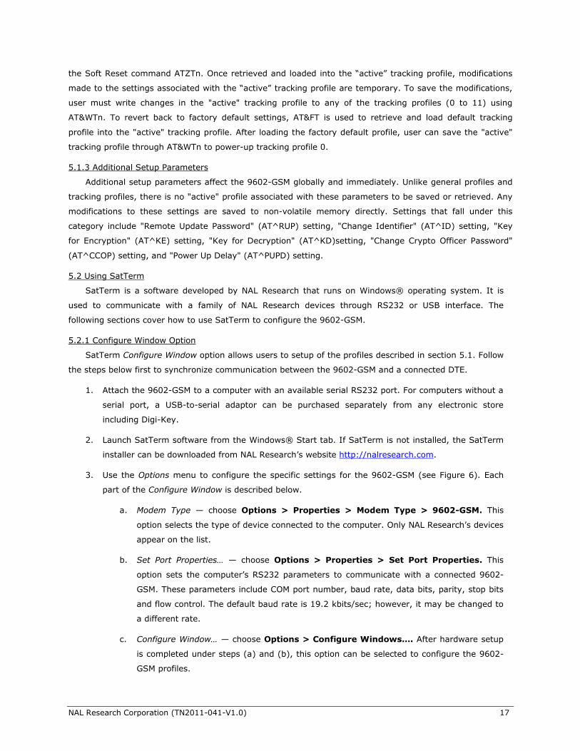
3. Use the Options menu to configure the specific settings for the 9602-GSM (see Figure 6). Each
part of the Configure Window is described below.
a. Modem Type — choose Options > Properties > Modem Type > 9602-GSM. This
option selects the type of device connected to the computer. Only NAL Research’s devices
appear on the list.
b. Set Port Properties… — choose Options > Properties > Set Port Properties. This
option sets the computer’s RS232 parameters to communicate with a connected 9602-
GSM. These parameters include COM port number, baud rate, data bits, parity, stop bits
and flow control. The default baud rate is 19.2 kbits/sec; however, it may be changed to
a different rate.
c. Configure Window… — choose Options > Configure Windows…. After hardware setup
is completed under steps (a) and (b), this option can be selected to configure the 9602-
GSM profiles.
NAL Research Corporation (TN2011-041-V1.0) 18
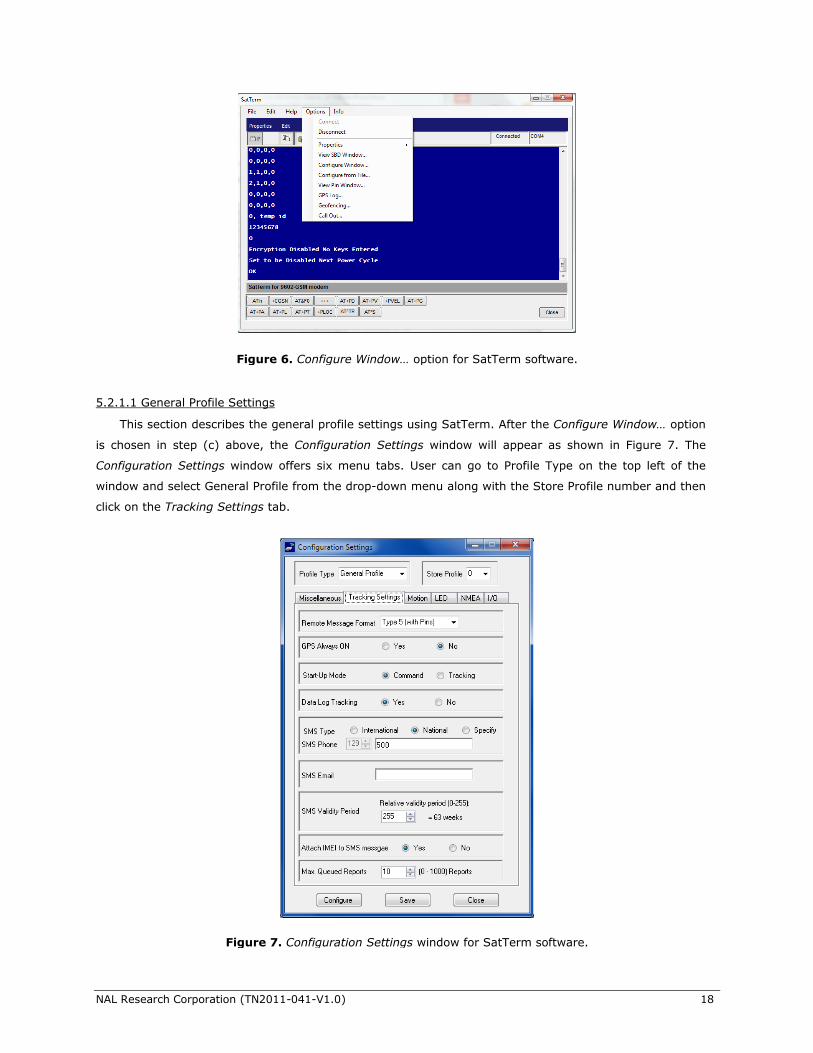
5.2.1.1 General Profile Settings
This section describes the general profile settings using SatTerm. After the Configure Window… option
is chosen in step (c) above, the Configuration Settings window will appear as shown in Figure 7. The
Configuration Settings window offers six menu tabs. User can go to Profile Type on the top left of the
window and select General Profile from the drop-down menu along with the Store Profile number and then
click on the Tracking Settings tab.
Figure 6. Configure Window… option for SatTerm software.
Figure 7. Configuration Settings window for SatTerm software.
NAL Research Corporation (TN2011-041-V1.0) 19
Tracking Settings
Tracking Settings offers nine settings as shown in Figure 7 — Remote Message Format, GPS Always
ON, Start-up Mode, Data Log Tracking, SMS Type/SMS Phone, SMS Email, SMS Validity Period, Attach
IMEI to SMS message, and Max. Queued Reports.
Remote Message Format
This option sets the format of the messages that will be sent from the 9602-GSM to the recipient. The
AT command associated with this setting is AT^RMF. Currently available message formats are:
1. GPS v3 (same format as on the A3LA trackers)
2. GPS v4 (includes HDOP and VDOP GPS values, and motion and low battery values)
3. GPS v5 (includes I/O pin states)
4. PECOS P3
5. PECOS P4
6. GPS v6 (includes short codes and free text fields)
7. 10 byte GPS version 0
GPS Always On
This option forces the GPS receiver to remain ON in between reports allowing the 9602-GSM to have
immediate location information (GPS hot start assuming the 9602-GSM always has full view of the sky)
each time it is ready to transmit a tracking report. When low-power consumption is not critical, enabling
the GPS receiver in between reports is recommended for faster GPS acquisition and more accurate
location information. Setting Callable to “No” (see Section 5.2.1.2) over-rides an enabled GPS Always On
and turns the GPS receiver off in between reports. The command associated with this setting is AT^GAO.
Start-Up Mode
This option sets the operating mode of the unit on power-up. The default is to power-up the unit in
Command mode allowing users to enter AT commands via a connected computer. Alternatively, the 9602-
GSM can also be configured to power-up in Tracking mode enabling it to automatically send reports at a
pre-determined interval. The AT command associated with this setting is AT^START.
Data Log Tracking
This option forces the 9602-GSM to save all tracking reports, whether successfully sent or attempted
to send during Tracking mode, to non-volatile memory. The device can save up to about 4,000 reports in
a circular memory (oldest saved reports are over-written when memory reaches maximum capacity).
SatTerm can be used to retrieve tracking reports at a later time using Options > GPS Log…. The AT
command associated with this setting is AT^DLTRK.
SMS Type/SMS Phone
This option sets the destination phone number of all reports sent as SMS messages using the GSM
link. If supported by the GSM carrier, a special phone number can be used to send SMS messages to an e-
mail address. For example, when using T-Mobile and in order to send to an e-mail address, the destination
number is set to 500. A destination e-mail address must also be specified in the SMS Email setting. Check
with the GSM carrier for proper destination number in order to send to an e-mail address. The AT
command associated with this setting is AT^TRKSMSD.
NAL Research Corporation (TN2011-041-V1.0) 20
SMS Email
This option sets the destination e-mail address when a special phone number is required to send to e-
mail. If the SMS destination is not a phone number, this setting should be kept blank. SMS Email setting is
only used for SMS messages sent over the GSM link. Check with the GSM carrier for proper destination
number to send to an e-mail address. The AT command associated with this setting is AT^TRKSMSE.
SMS Validity Period
This option sets how long an SMS message is stored in the GSM carrier’s SMS service center when an
SMS message cannot be delivered. This setting is only used for SMS message sent over the GSM link. The
AT command associated with this setting is AT^TRKSMSVP.
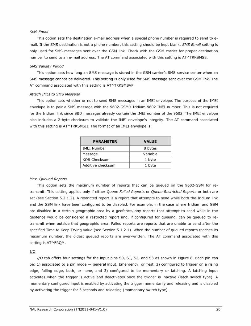
Attach IMEI to SMS Message
This option sets whether or not to send SMS messages in an IMEI envelope. The purpose of the IMEI
envelope is to pair a SMS message with the 9602-GSM’s Iridium 9602 IMEI number. This is not required
for the Iridium link since SBD messages already contain the IMEI number of the 9602. The IMEI envelope
also includes a 2-byte checksum to validate the IMEI envelope's integrity. The AT command associated
with this setting is AT^TRKSMSII. The format of an IMEI envelope is:
Max. Queued Reports
This option sets the maximum number of reports that can be queued on the 9602-GSM for re-
transmit. This setting applies only if either Queue Failed Reports or Queue Restricted Reports or both are
set (see Section 5.2.1.2). A restricted report is a report that attempts to send while both the Iridium link
and the GSM link have been configured to be disabled. For example, in the case where Iridium and GSM
are disabled in a certain geographic area by a geofence, any reports that attempt to send while in the
geofence would be considered a restricted report and, if configured for queuing, can be queued to re-
transmit when outside that geographic area. Failed reports are reports that are unable to send after the
specified Time to Keep Trying value (see Section 5.1.2.1). When the number of queued reports reaches its
maximum number, the oldest queued reports are over-written. The AT command associated with this
setting is AT^ERQM.
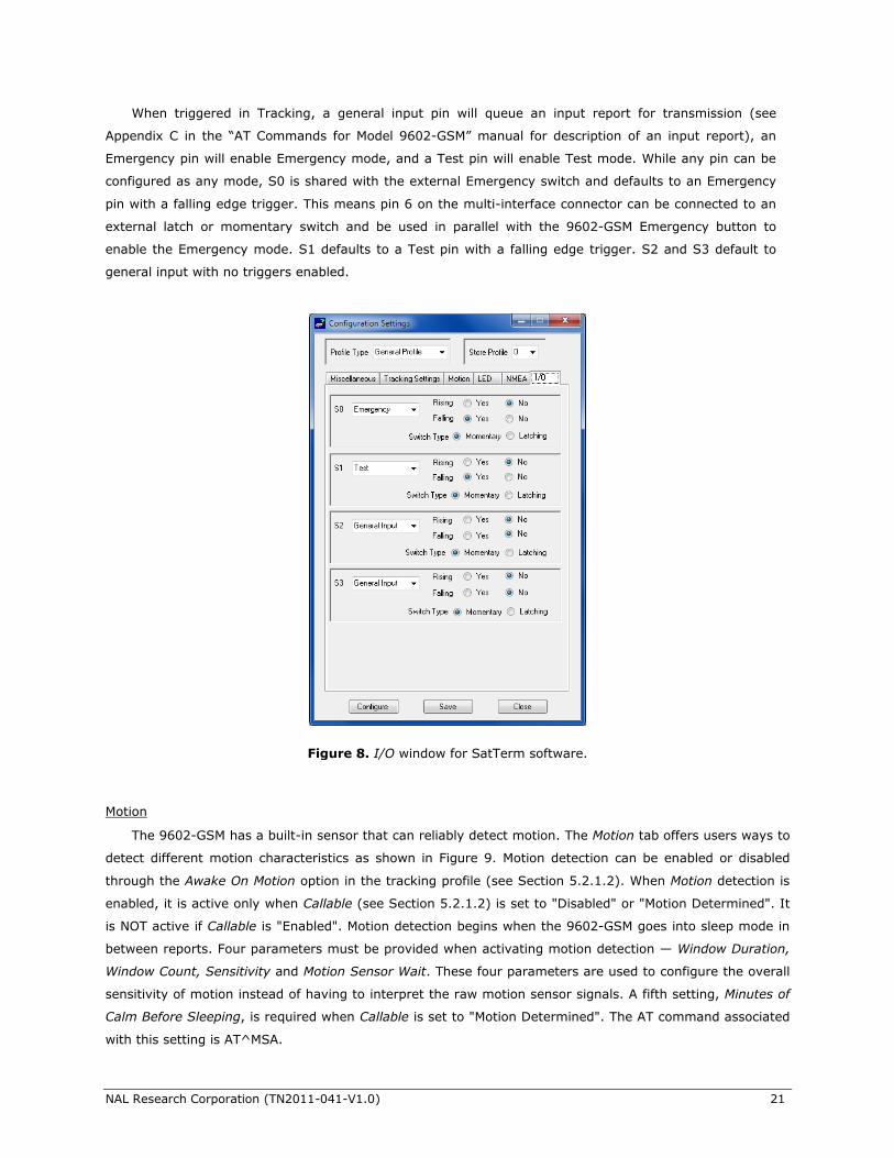
I/O
I/O tab offers four settings for the input pins S0, S1, S2, and S3 as shown in Figure 8. Each pin can
be: 1) associated to a pin mode — general input, Emergency, or Test, 2) configured to trigger on a rising
edge, falling edge, both, or none, and 3) configured to be momentary or latching. A latching input
activates when the trigger is active and deactivates once the trigger is inactive (latch switch type). A
momentary configured input is enabled by activating the trigger momentarily and releasing and is disabled
by activating the trigger for 3 seconds and releasing (momentary switch type).
PARAMETER VALUE
IMEI Number 8 bytes
Message Variable
XOR Checksum 1 byte
Additive checksum 1 byte
NAL Research Corporation (TN2011-041-V1.0) 21
When triggered in Tracking, a general input pin will queue an input report for transmission (see
Appendix C in the “AT Commands for Model 9602-GSM” manual for description of an input report), an
Emergency pin will enable Emergency mode, and a Test pin will enable Test mode. While any pin can be
configured as any mode, S0 is shared with the external Emergency switch and defaults to an Emergency
pin with a falling edge trigger. This means pin 6 on the multi-interface connector can be connected to an
external latch or momentary switch and be used in parallel with the 9602-GSM Emergency button to
enable the Emergency mode. S1 defaults to a Test pin with a falling edge trigger. S2 and S3 default to
general input with no triggers enabled.
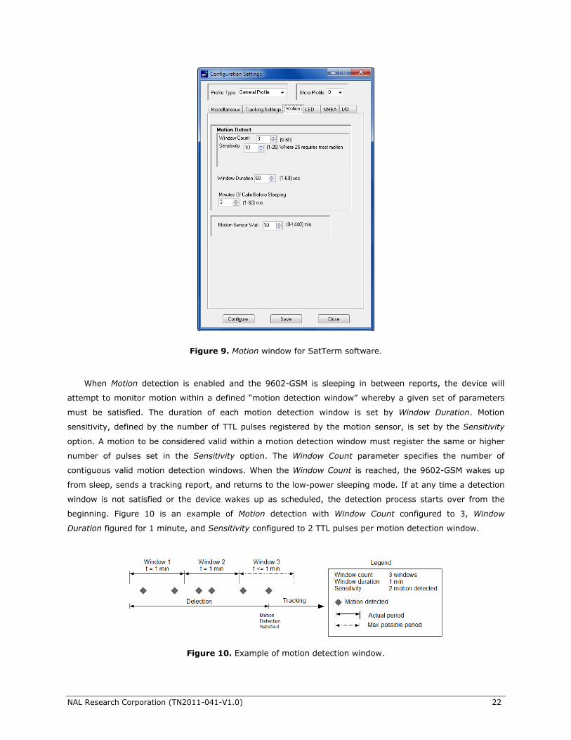
Motion
The 9602-GSM has a built-in sensor that can reliably detect motion. The Motion tab offers users ways to
detect different motion characteristics as shown in Figure 9. Motion detection can be enabled or disabled
through the Awake On Motion option in the tracking profile (see Section 5.2.1.2). When Motion detection is
enabled, it is active only when Callable (see Section 5.2.1.2) is set to "Disabled" or "Motion Determined". It
is NOT active if Callable is "Enabled". Motion detection begins when the 9602-GSM goes into sleep mode in
between reports. Four parameters must be provided when activating motion detection — Window Duration,
Window Count, Sensitivity and Motion Sensor Wait. These four parameters are used to configure the overall
sensitivity of motion instead of having to interpret the raw motion sensor signals. A fifth setting, Minutes of
Calm Before Sleeping, is required when Callable is set to "Motion Determined". The AT command associated
with this setting is AT^MSA.
Figure 8. I/O window for SatTerm software.
NAL Research Corporation (TN2011-041-V1.0) 22
When Motion detection is enabled and the 9602-GSM is sleeping in between reports, the device will
attempt to monitor motion within a defined “motion detection window” whereby a given set of parameters
must be satisfied. The duration of each motion detection window is set by Window Duration. Motion
sensitivity, defined by the number of TTL pulses registered by the motion sensor, is set by the Sensitivity
option. A motion to be considered valid within a motion detection window must register the same or higher
number of pulses set in the Sensitivity option. The Window Count parameter specifies the number of
contiguous valid motion detection windows. When the Window Count is reached, the 9602-GSM wakes up
from sleep, sends a tracking report, and returns to the low-power sleeping mode. If at any time a detection
window is not satisfied or the device wakes up as scheduled, the detection process starts over from the
beginning. Figure 10 is an example of Motion detection with Window Count configured to 3, Window
Duration figured for 1 minute, and Sensitivity configured to 2 TTL pulses per motion detection window.
Figure 10. Example of motion detection window.
Figure 9. Motion window for SatTerm software.
NAL Research Corporation (TN2011-041-V1.0) 23
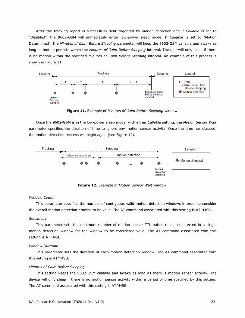
After the tracking report is successfully sent triggered by Motion detection and if Callable is set to
"Disabled", the 9602-GSM will immediately enter low-power sleep mode. If Callable is set to "Motion
Determined", the Minutes of Calm Before Sleeping parameter will keep the 9602-GSM callable and awake as
long as motion persists within the Minutes of Calm Before Sleeping interval. The unit will only sleep if there
is no motion within the specified Minutes of Calm Before Sleeping interval. An example of this process is
shown in Figure 11.
Once the 9602-GSM is in the low-power sleep mode, with either Callable setting, the Motion Sensor Wait
parameter specifies the duration of time to ignore any motion sensor activity. Once the time has elapsed,
the motion detection process will begin again (see Figure 12).
Window Count
This parameter specifies the number of contiguous valid motion detection windows in order to consider
the overall motion detection process to be valid. The AT command associated with this setting is AT^MSB.
Sensitivity
This parameter sets the minimum number of motion sensor TTL pulses must be detected in a single
motion detection window for the window to be considered valid. The AT command associated with this
setting is AT^MSB.
Window Duration
This parameter sets the duration of each motion detection window. The AT command associated with
this setting is AT^MSB.
Minutes of Calm Before Sleeping
This setting keeps the 9602-GSM callable and awake as long as there is motion sensor activity. The
device will only sleep if there is no motion sensor activity within a period of time specified by this setting.
The AT command associated with this setting is AT^MSE.
Figure 11. Example of Minutes of Calm Before Sleeping window.
Figure 12. Example of Motion Sensor Wait window.
NAL Research Corporation (TN2011-041-V1.0) 24
Motion Sensor Wait
This setting specifies the duration of time to ignore the motion sensor when the 9602-GSM is in sleep
mode. Once that time has elapsed, motion detection will begin again. The related AT command is AT^MSW.
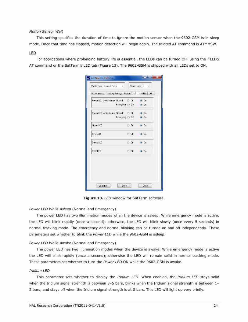
LED
For applications where prolonging battery life is essential, the LEDs can be turned OFF using the ^LEDS
AT command or the SatTerm’s LED tab (Figure 13). The 9602-GSM is shipped with all LEDs set to ON.
Power LED While Asleep (Normal and Emergency)
The power LED has two illumination modes when the device is asleep. While emergency mode is active,
the LED will blink rapidly (once a second); otherwise, the LED will blink slowly (once every 5 seconds) in
normal tracking mode. The emergency and normal blinking can be turned on and off independently. These
parameters set whether to blink the Power LED while the 9602-GSM is asleep.
Power LED While Awake (Normal and Emergency)
The power LED has two illumination modes when the device is awake. While emergency mode is active
the LED will blink rapidly (once a second); otherwise the LED will remain solid in normal tracking mode.
These parameters set whether to turn the Power LED ON while the 9602-GSM is awake.
Iridium LED
This parameter sets whether to display the Iridium LED. When enabled, the Iridium LED stays solid
when the Iridium signal strength is between 3–5 bars, blinks when the Iridium signal strength is between 1–
2 bars, and stays off when the Iridium signal strength is at 0 bars. This LED will light up very briefly.
Figure 13. LED window for SatTerm software.
NAL Research Corporation (TN2011-041-V1.0) 25
GPS LED
This parameter sets whether to display the GPS LED. When enabled, the GPS LED stays solid when
there is a valid GPS position fix, blinks when there is 2D fix or using dead reckoning, and stays off when
unable to obtain a position fix. This LED might light up very briefly.
Status LED
This parameter sets whether to display the Status LED. When enabled and during Tracking mode, this
LED stays solid if the last SBD/SMS transmission was successfully, blinks if the last SBD/SMS transmission
was unsuccessfully, and stays off if no SBD/SMS transmission was sent.
GSM LED
This parameter sets whether to display the GSM LED. When enabled, the GSM LED stays solid when the
GSM signal strength is between 3–5 bars, blinks when the GSM signal strength is between 1–2 bars, and
stays off when the GSM signal strength is at 0 bars. This LED will light up very briefly.
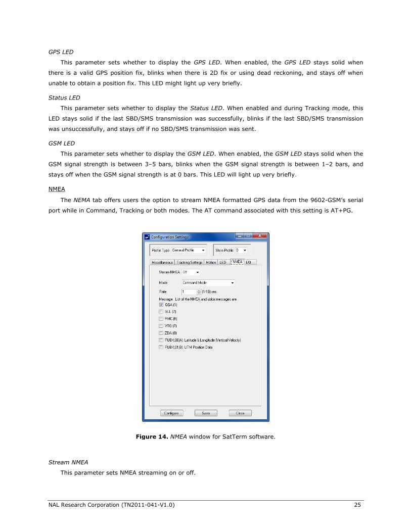
NMEA
The NEMA tab offers users the option to stream NMEA formatted GPS data from the 9602-GSM’s serial
port while in Command, Tracking or both modes. The AT command associated with this setting is AT+PG.
Stream NMEA
This parameter sets NMEA streaming on or off.
Figure 14. NMEA window for SatTerm software.
NAL Research Corporation (TN2011-041-V1.0) 26
Mode
This parameter selects the mode (Tracking, Command or both modes) in which GPS data streaming is
active.
Rate
This parameter sets the NMEA streaming update rate in seconds.
Message
The checked boxes select which NMEA packages are streamed through the 9602-GSM’s serial port.
Though the default serial port baud rate of 19.2 kbits/sec is sufficient to stream the entire set of NMEA
messages at a 1-second rate, care should be taken to select an appropriate streaming rate when using lower
serial baud rates.
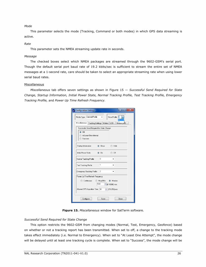
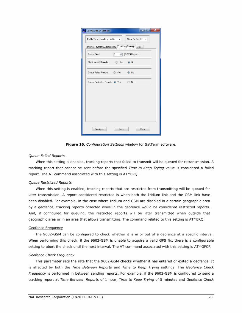
Miscellaneous
Miscellaneous tab offers seven settings as shown in Figure 15 — Successful Send Required for State
Change, Startup Information, Initial Power State, Normal Tracking Profile, Test Tracking Profile, Emergency
Tracking Profile, and Power Up Time Refresh Frequency.
Successful Send Required for State Change
This option restricts the 9602-GSM from changing modes (Normal, Test, Emergency, Geofence) based
on whether or not a tracking report has been transmitted. When set to off, a change to the tracking mode
takes effect immediately (i.e. Normal to Emergency). When set to “At Least One Attempt”, the mode change
will be delayed until at least one tracking cycle is complete. When set to “Success”, the mode change will be
Figure 15. Miscellaneous window for SatTerm software.
NAL Research Corporation (TN2011-041-V1.0) 27
blocked until a tracking report is transmitted successfully. The AT command associated with this setting is
AT^SSR.
Statup Information
This option hides/shows the power-up text (copyright, model number, etc.) that is echoed to the 9602-
GSM’s serial port. The AT command associated with this setting is AT^START.
Initial Power State
This option sets whether the device is powered up when DC power is applied (On) or if the power button
must first be pressed to power up the unit (Off). The command associated with this setting is AT^IPS.
Normal Tracking Profile
This option selects the stored tracking profile to be used in Normal mode. The AT command associated
with this setting is AT^TPN.
Test Tracking Profile
This option selects the stored tracking profile to be used in Test mode. The AT command associated with
this setting is AT^TPT.
Emergency Tracking Profile
This option selects the stored tracking profile to be used in Emergency mode. The AT command
associated with this setting is AT^TPE.
Power Up Time Refresh Frequency
Periodically, the 9602-GSM wakes up from sleep to adjust its internal clock against the GPS receiver
timing signal. In the case when the GPS receiver does not yet have a time fix, the 9602-GSM will stay
awake for a specified period of time (Allowed GPS Acquisition Time) waiting for a GPS time fix. After which,
the 9602-GSM will sleep for another period of time (Power Up Time Refresh Frequency) before retrying to
find a time fix. These values are configured through an AT command (^PUPT).
5.2.1.2 Tracking Profile Settings
This section covers the configuration tabs associated with the tracking profile settings. After the
Configure Window… option is selected, users can go to Profile Type on the top left of the window and
select Tracking Profile along with the Store Profile number (Figure 16).
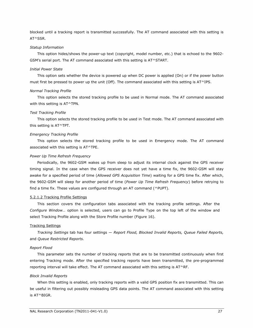
Tracking Settings
Tracking Settings tab has four settings — Report Flood, Blocked Invalid Reports, Queue Failed Reports,
and Queue Restricted Reports.
Report Flood
This parameter sets the number of tracking reports that are to be transmitted continuously when first
entering Tracking mode. After the specified tracking reports have been transmitted, the pre-programmed
reporting interval will take effect. The AT command associated with this setting is AT^RF.
Block Invalid Reports
When this setting is enabled, only tracking reports with a valid GPS position fix are transmitted. This can
be useful in filtering out possibly misleading GPS data points. The AT command associated with this setting
is AT^BIGR.
NAL Research Corporation (TN2011-041-V1.0) 28
Queue Failed Reports
When this setting is enabled, tracking reports that failed to transmit will be queued for retransmission. A
tracking report that cannot be sent before the specified Time-to-Keep-Trying value is considered a failed
report. The AT command associated with this setting is AT^ERQ.
Queue Restricted Reports
When this setting is enabled, tracking reports that are restricted from transmitting will be queued for
later transmission. A report considered restricted is when both the Iridium link and the GSM link have
been disabled. For example, in the case where Iridium and GSM are disabled in a certain geographic area
by a geofence, tracking reports collected while in the geofence would be considered restricted reports.
And, if configured for queuing, the restricted reports will be later transmitted when outside that
geographic area or in an area that allows transmitting. The command related to this setting is AT^ERQ.
Geofence Frequency
The 9602-GSM can be configured to check whether it is in or out of a geofence at a specific interval.
When performing this check, if the 9602-GSM is unable to acquire a valid GPS fix, there is a configurable
setting to abort the check until the next interval. The AT command associated with this setting is AT^GFCF.
Geofence Check Frequency
This parameter sets the rate that the 9602-GSM checks whether it has entered or exited a geofence. It
is affected by both the Time Between Reports and Time to Keep Trying settings. The Geofence Check
Frequency is performed in between sending reports. For example, if the 9602-GSM is configured to send a
tracking report at Time Between Reports of 1 hour, Time to Keep Trying of 5 minutes and Geofence Check
Figure 16. Configuration Settings window for SatTerm software.
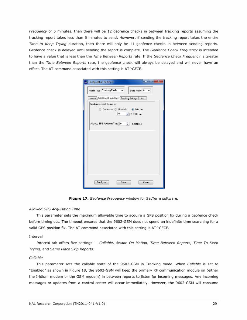
NAL Research Corporation (TN2011-041-V1.0) 29
Frequency of 5 minutes, then there will be 12 geofence checks in between tracking reports assuming the
tracking report takes less than 5 minutes to send. However, if sending the tracking report takes the entire
Time to Keep Trying duration, then there will only be 11 geofence checks in between sending reports.
Geofence check is delayed until sending the report is complete. The Geofence Check Frequency is intended
to have a value that is less than the Time Between Reports rate. If the Geofence Check Frequency is greater
than the Time Between Reports rate, the geofence check will always be delayed and will never have an
effect. The AT command associated with this setting is AT^GFCF.
Allowed GPS Acquisition Time
This parameter sets the maximum allowable time to acquire a GPS position fix during a geofence check
before timing out. The timeout ensures that the 9602-GSM does not spend an indefinite time searching for a
valid GPS position fix. The AT command associated with this setting is AT^GFCF.
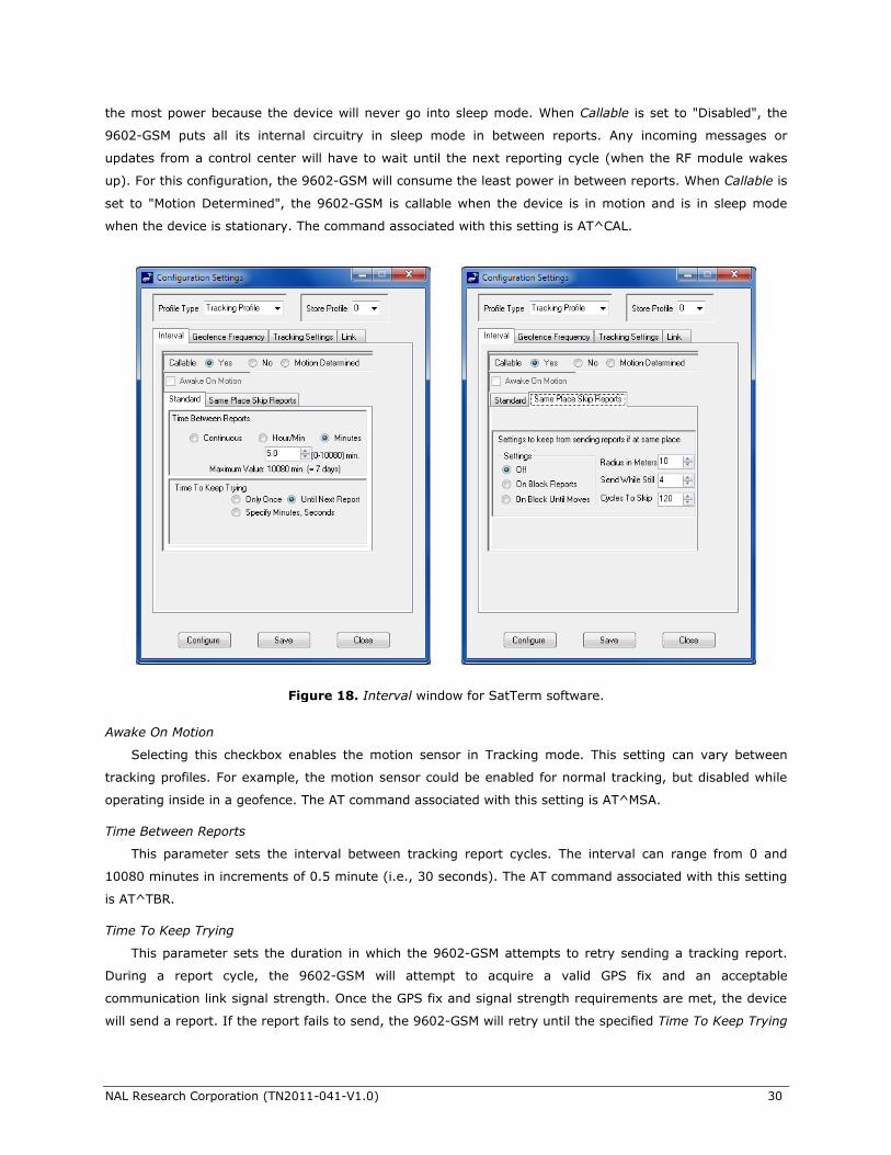
Interval
Interval tab offers five settings — Callable, Awake On Motion, Time Between Reports, Time To Keep
Trying, and Same Place Skip Reports.
Callable
This parameter sets the callable state of the 9602-GSM in Tracking mode. When Callable is set to
"Enabled" as shown in Figure 18, the 9602-GSM will keep the primary RF communication module on (either
the Iridium modem or the GSM modem) in between reports to listen for incoming messages. Any incoming
messages or updates from a control center will occur immediately. However, the 9602-GSM will consume
Figure 17. Geofence Frequency window for SatTerm software.
NAL Research Corporation (TN2011-041-V1.0) 30
the most power because the device will never go into sleep mode. When Callable is set to "Disabled", the
9602-GSM puts all its internal circuitry in sleep mode in between reports. Any incoming messages or
updates from a control center will have to wait until the next reporting cycle (when the RF module wakes
up). For this configuration, the 9602-GSM will consume the least power in between reports. When Callable is
set to "Motion Determined", the 9602-GSM is callable when the device is in motion and is in sleep mode
when the device is stationary. The command associated with this setting is AT^CAL.
Awake On Motion
Selecting this checkbox enables the motion sensor in Tracking mode. This setting can vary between
tracking profiles. For example, the motion sensor could be enabled for normal tracking, but disabled while
operating inside in a geofence. The AT command associated with this setting is AT^MSA.
Time Between Reports
This parameter sets the interval between tracking report cycles. The interval can range from 0 and
10080 minutes in increments of 0.5 minute (i.e., 30 seconds). The AT command associated with this setting
is AT^TBR.
Time To Keep Trying
This parameter sets the duration in which the 9602-GSM attempts to retry sending a tracking report.
During a report cycle, the 9602-GSM will attempt to acquire a valid GPS fix and an acceptable
communication link signal strength. Once the GPS fix and signal strength requirements are met, the device
will send a report. If the report fails to send, the 9602-GSM will retry until the specified Time To Keep Trying
Figure 18. Interval window for SatTerm software.
NAL Research Corporation (TN2011-041-V1.0) 31
window expires. There are two additional special values for Time To Keep Trying – Only Once and Until Next
Report. Only Once will force the 9602-GSM to send only once per report cycle regardless of whether the
tracking report was successfully transmitted or not. Until Next Report will force the 9602-GMS to retry
sending a tracking report up to the next reporting cycle if there is no successful transmission. Time To Keep
Trying is specified in 5-second increments. It has a minimum value of 1.5 minutes and a maximum value of
21 minutes and 10 seconds. The AT command associated with this setting is AT^TTKT.
Same Place Skip Reports
This parameter limits the 9602-GSM from sending tracking reports when it has not moved out of a
specified radius. When enabled, Same Place Skip Reports causes the unit to be bounded by a sphere with a
specified radius. Report sending is halted when the unit remains in the sphere for a specified Cycles to Skip
number of report cycles. When the specified Cycles to Skip value is reached, the 9602-GSM will report for a
specified Send While Still cycles. The process is repeated until the unit leaves the sphere. Upon leaving the
bounding sphere, a new boundary will be created at the current location of the unit and the 9602-GSM will
report for the specified Send While Still cycles. If On Block Until Moves is selected, the Cycles To Skip
parameter is disregarded and the unit only sends the Send While Still cycles each time it moves out of the
sphere. The AT command associated with this setting is AT^SPSR.
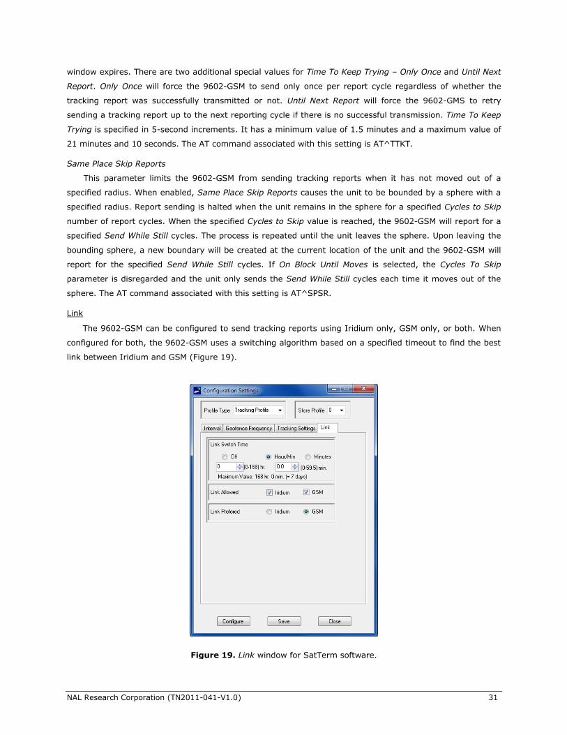
Link
The 9602-GSM can be configured to send tracking reports using Iridium only, GSM only, or both. When
configured for both, the 9602-GSM uses a switching algorithm based on a specified timeout to find the best
link between Iridium and GSM (Figure 19).
Figure 19. Link window for SatTerm software.
NAL Research Corporation (TN2011-041-V1.0) 32
Link Switch Time
This is the timeout for switching between communication links when the current link fails to successfully
send a report. This parameter applies only if the Links Allowed setting is configured to both and Links
Preferred is configured to either Iridium or GSM. For example, if Links Allowed is configured to both, Links
Preferred is configured to Iridium, and Link Switch Time is configured to 30 seconds, the 9602-GSM will
switch to GSM if unable to send a tracking report via Iridium within 30 seconds. Subsequently, the device
will either toggle between Iridium and GSM until a successful tracking report is sent or stop when the Time
to Keep Trying value is reached. The AT command associated with this setting is AT^LNKSWT.
Links Allowed
This option sets an active communication link – Iridium and/or GSM. When set to Iridium or GSM, the
9602-GSM will only send tracking reports using the Iridium link or GSM link, respectively. And when set to
both, the device will toggle between Iridium and GSM using the timeout value configured in the Link Switch
Time setting. The AT command associated with this setting is AT^LNK.
Links Preferred
This option sets the preferred communication link – either Iridium or GSM. When the Links Allowed
setting is configured to both, the first communication link used to send a report is the preferred link.
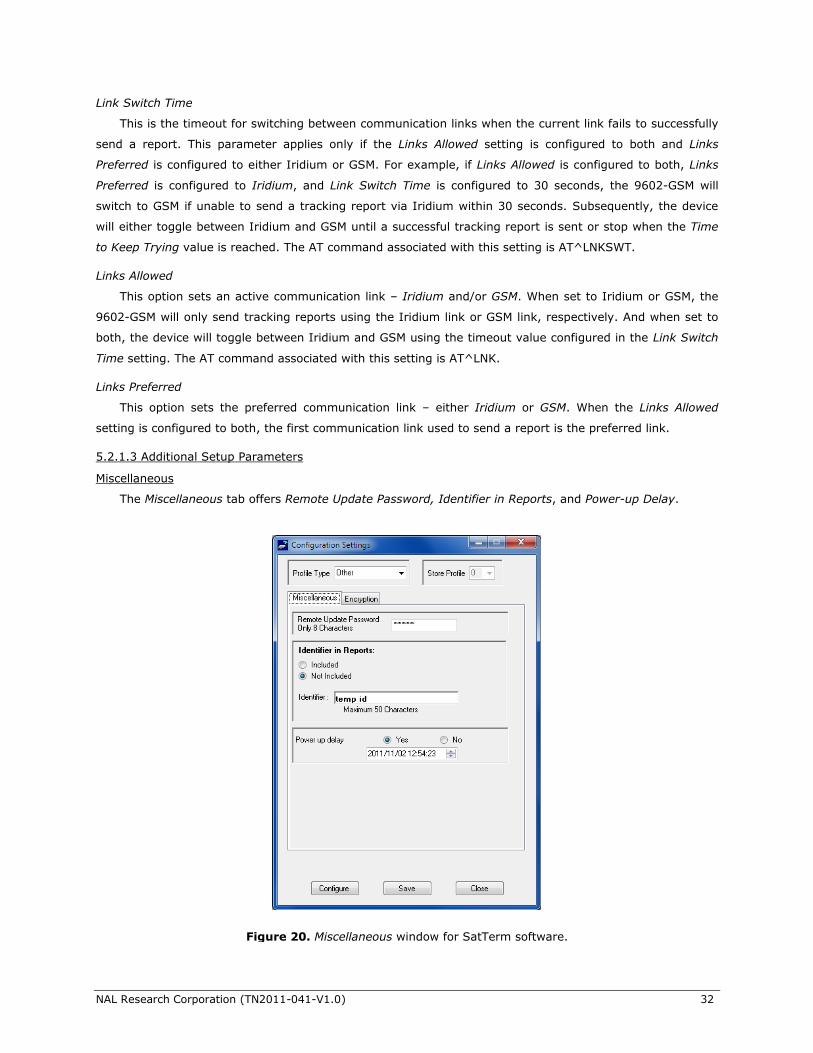
5.2.1.3 Additional Setup Parameters
Miscellaneous
The Miscellaneous tab offers Remote Update Password, Identifier in Reports, and Power-up Delay.
Figure 20. Miscellaneous window for SatTerm software.
NAL Research Corporation (TN2011-041-V1.0) 33
Remote Update Password
Unattended 9602-GSM can be reconfigured without requiring direct access to the device. All of the
tracking profile parameters and most of the general parameters can be configured via remote updates. This
parameter sets the required remote update password. The <password> entered must be eight characters in
length. All printable characters are allowed. The factory-set default password is 12345678 and user can
keep it as-is. There is no requirement for this password to be changed. The AT command associated with
this setting is AT^RUP.
Identifier in Reports
Tracking reports from a 9602-GSM can be identified by its Iridium 9602 IMEI number. The IMEI
number is included by default when transmitted via SBD. However, Attach IMEI to SMS Message must be
enabled when transmitted via GSM to have the IMEI number included in the reports. In addition, unique
device name can be assigned to the 9602-GSM. Identifier in Reports parameter sets an identifier of up to
50 characters (platform identifier of the 9602-GSM) to be included in the tracking report. User should
keep the identifier short to reduce airtime cost especially when on the Iridium link. The AT command
associated with this setting is AT^ID.
Power up Delay
This parameter enables the power-up delay to a specified date and time. The date and time format is as
follow YYYY/MM/DD HH:MM:SS (i.e., 2012/11/30 12:54:23). When in Tracking mode and immediately after
power is applied to the 9602-GSM, the device remains in a power-saving sleep mode until the user-specified
date and time. And at which point, the device enters Tracking mode. The AT command associated with this
setting is AT^PUPD.
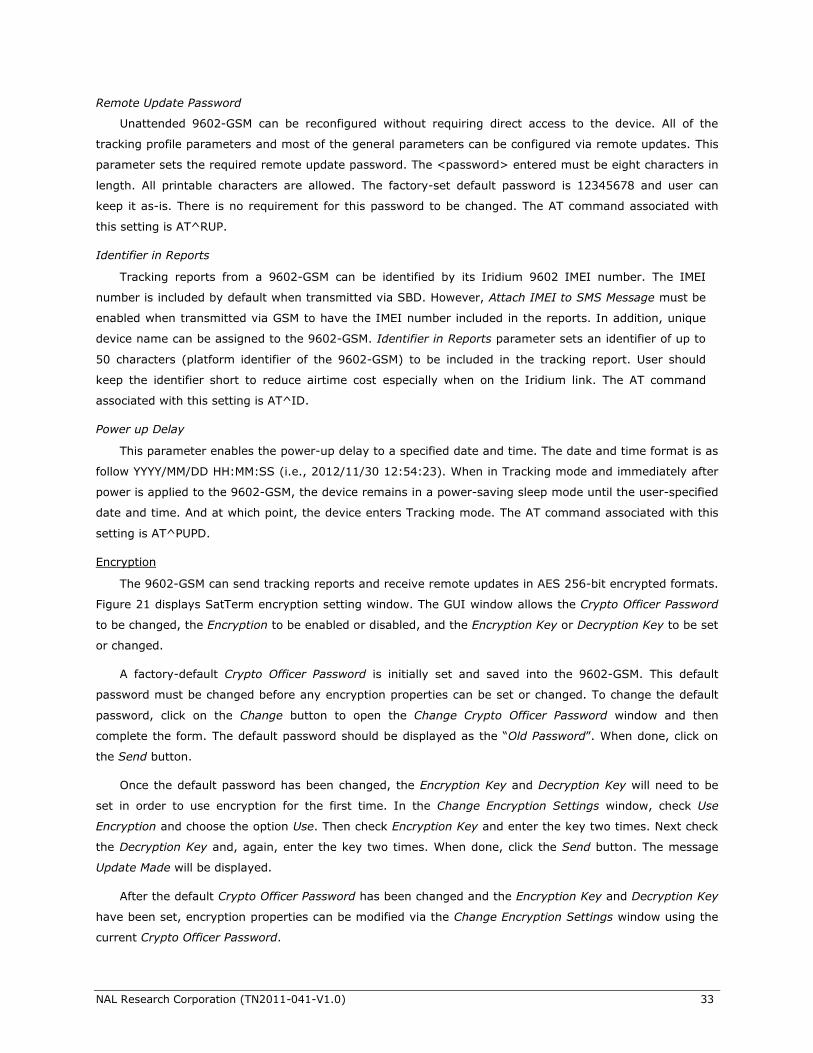
Encryption
The 9602-GSM can send tracking reports and receive remote updates in AES 256-bit encrypted formats.
Figure 21 displays SatTerm encryption setting window. The GUI window allows the Crypto Officer Password
to be changed, the Encryption to be enabled or disabled, and the Encryption Key or Decryption Key to be set
or changed.
A factory-default Crypto Officer Password is initially set and saved into the 9602-GSM. This default
password must be changed before any encryption properties can be set or changed. To change the default
password, click on the Change button to open the Change Crypto Officer Password window and then
complete the form. The default password should be displayed as the “Old Password”. When done, click on
the Send button.
Once the default password has been changed, the Encryption Key and Decryption Key will need to be
set in order to use encryption for the first time. In the Change Encryption Settings window, check Use
Encryption and choose the option Use. Then check Encryption Key and enter the key two times. Next check
the Decryption Key and, again, enter the key two times. When done, click the Send button. The message
Update Made will be displayed.
After the default Crypto Officer Password has been changed and the Encryption Key and Decryption Key
have been set, encryption properties can be modified via the Change Encryption Settings window using the
current Crypto Officer Password.
NAL Research Corporation (TN2011-041-V1.0) 34
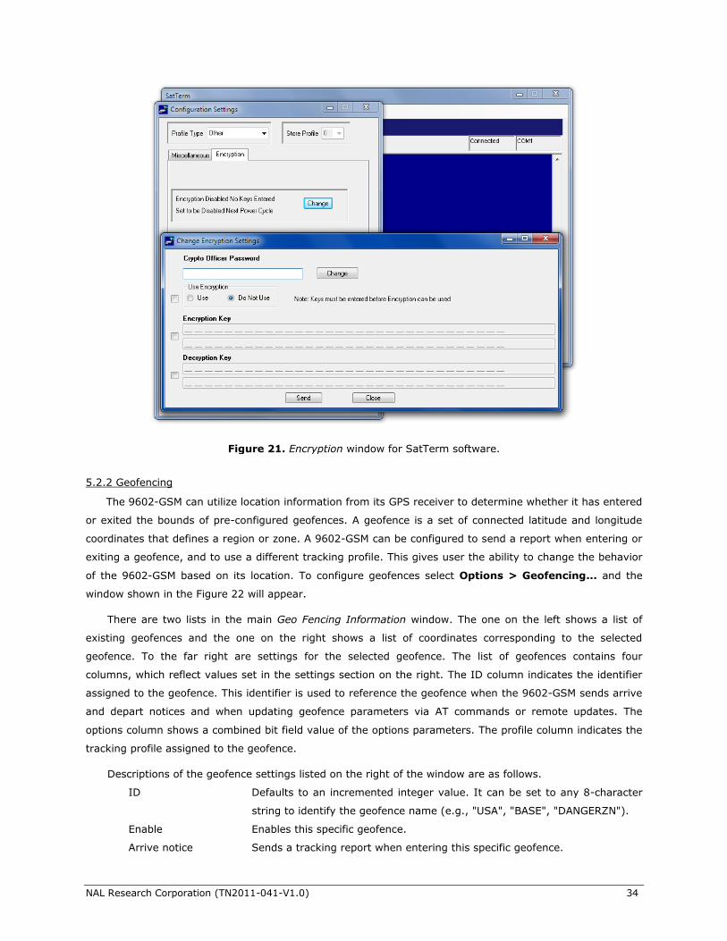
5.2.2 Geofencing
The 9602-GSM can utilize location information from its GPS receiver to determine whether it has entered
or exited the bounds of pre-configured geofences. A geofence is a set of connected latitude and longitude
coordinates that defines a region or zone. A 9602-GSM can be configured to send a report when entering or
exiting a geofence, and to use a different tracking profile. This gives user the ability to change the behavior
of the 9602-GSM based on its location. To configure geofences select Options > Geofencing... and the
window shown in the Figure 22 will appear.
There are two lists in the main Geo Fencing Information window. The one on the left shows a list of
existing geofences and the one on the right shows a list of coordinates corresponding to the selected
geofence. To the far right are settings for the selected geofence. The list of geofences contains four
columns, which reflect values set in the settings section on the right. The ID column indicates the identifier
assigned to the geofence. This identifier is used to reference the geofence when the 9602-GSM sends arrive
and depart notices and when updating geofence parameters via AT commands or remote updates. The
options column shows a combined bit field value of the options parameters. The profile column indicates the
tracking profile assigned to the geofence.
Descriptions of the geofence settings listed on the right of the window are as follows.
ID Defaults to an incremented integer value. It can be set to any 8-character
string to identify the geofence name (e.g., "USA", "BASE", "DANGERZN").
Enable Enables this specific geofence.
Arrive notice Sends a tracking report when entering this specific geofence.
Figure 21. Encryption window for SatTerm software.
NAL Research Corporation (TN2011-041-V1.0) 35
Depart notice Sends a tracking report when exiting this specific geofence.
Profile Sets a tracking profile to be used while inside this specific geofence.
At the bottom of the Geo Fencing Information window are a set of buttons. Descriptions of the buttons
are as follows.
Configure Selecting the configure button saves the list of geofences on the 9602-GSM.
Delete Deletes the selected geofence.
Clear Deletes all configured geofences.
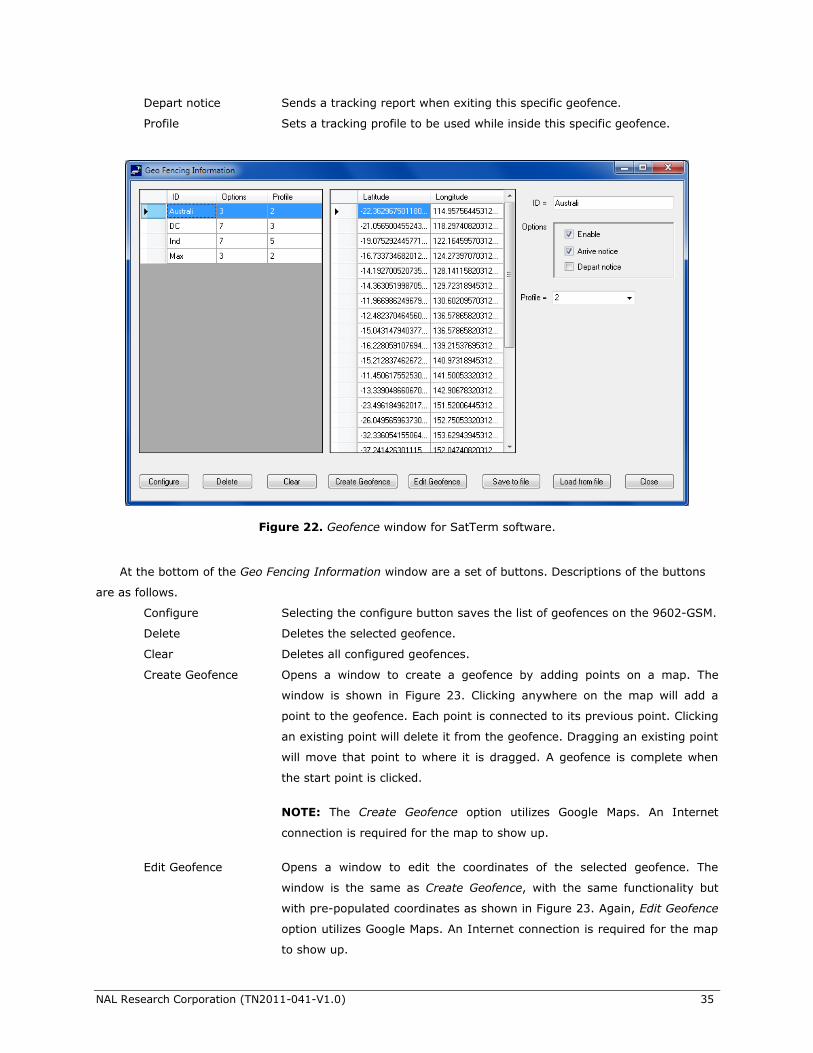
Create Geofence Opens a window to create a geofence by adding points on a map. The
window is shown in Figure 23. Clicking anywhere on the map will add a
point to the geofence. Each point is connected to its previous point. Clicking
an existing point will delete it from the geofence. Dragging an existing point
will move that point to where it is dragged. A geofence is complete when
the start point is clicked.
NOTE: The Create Geofence option utilizes Google Maps. An Internet
connection is required for the map to show up.
Edit Geofence Opens a window to edit the coordinates of the selected geofence. The
window is the same as Create Geofence, with the same functionality but
with pre-populated coordinates as shown in Figure 23. Again, Edit Geofence
option utilizes Google Maps. An Internet connection is required for the map
to show up.
Figure 22. Geofence window for SatTerm software.
NAL Research Corporation (TN2011-041-V1.0) 36
Save to Excel Saves the list of geofences to an Excel defined Comma Separated Values
(CSV) file.
Load from file Loads geofences from a Comma Separated Values (CSV) file.
Close Closes the Geo Fencing Information window.
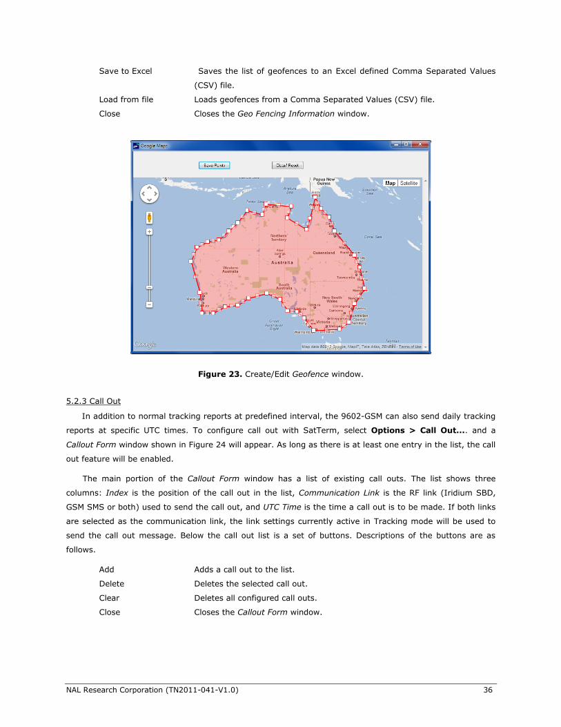
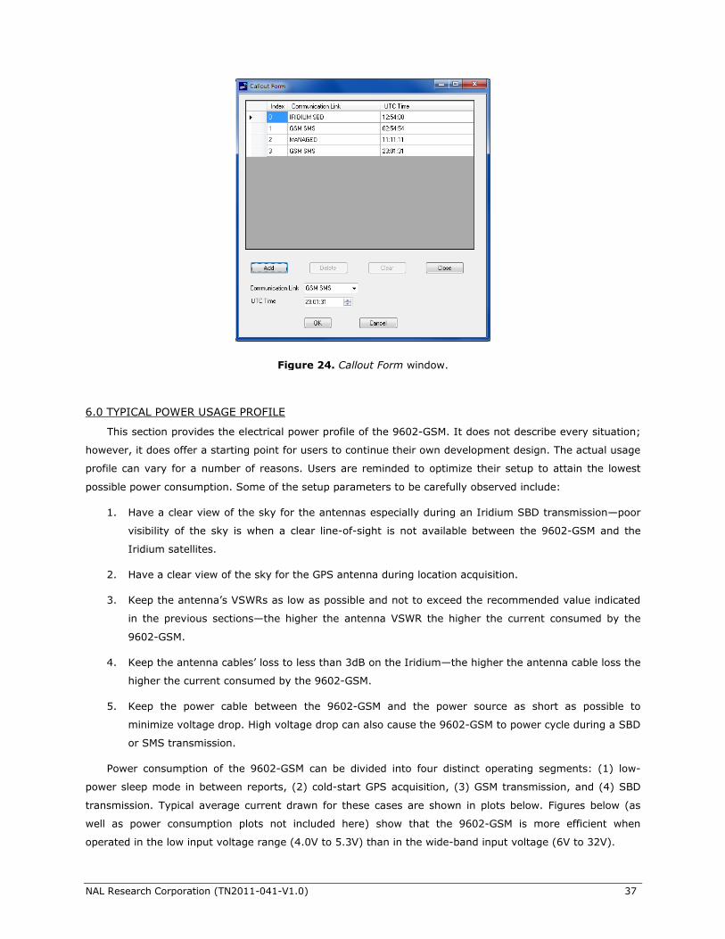
5.2.3 Call Out
In addition to normal tracking reports at predefined interval, the 9602-GSM can also send daily tracking
reports at specific UTC times. To configure call out with SatTerm, select Options > Call Out.... and a
Callout Form window shown in Figure 24 will appear. As long as there is at least one entry in the list, the call
out feature will be enabled.
The main portion of the Callout Form window has a list of existing call outs. The list shows three
columns: Index is the position of the call out in the list, Communication Link is the RF link (Iridium SBD,
GSM SMS or both) used to send the call out, and UTC Time is the time a call out is to be made. If both links
are selected as the communication link, the link settings currently active in Tracking mode will be used to
send the call out message. Below the call out list is a set of buttons. Descriptions of the buttons are as
follows.
Add Adds a call out to the list.
Delete Deletes the selected call out.
Clear Deletes all configured call outs.
Close Closes the Callout Form window.
Figure 23. Create/Edit Geofence window.
NAL Research Corporation (TN2011-041-V1.0) 37
6.0 TYPICAL POWER USAGE PROFILE
This section provides the electrical power profile of the 9602-GSM. It does not describe every situation;
however, it does offer a starting point for users to continue their own development design. The actual usage
profile can vary for a number of reasons. Users are reminded to optimize their setup to attain the lowest
possible power consumption. Some of the setup parameters to be carefully observed include:
1. Have a clear view of the sky for the antennas especially during an Iridium SBD transmission—poor
visibility of the sky is when a clear line-of-sight is not available between the 9602-GSM and the
Iridium satellites.
2. Have a clear view of the sky for the GPS antenna during location acquisition.
3. Keep the antenna’s VSWRs as low as possible and not to exceed the recommended value indicated
in the previous sections—the higher the antenna VSWR the higher the current consumed by the
9602-GSM.
4. Keep the antenna cables’ loss to less than 3dB on the Iridium—the higher the antenna cable loss the
higher the current consumed by the 9602-GSM.
5. Keep the power cable between the 9602-GSM and the power source as short as possible to
minimize voltage drop. High voltage drop can also cause the 9602-GSM to power cycle during a SBD
or SMS transmission.
Power consumption of the 9602-GSM can be divided into four distinct operating segments: (1) low-
power sleep mode in between reports, (2) cold-start GPS acquisition, (3) GSM transmission, and (4) SBD
transmission. Typical average current drawn for these cases are shown in plots below. Figures below (as
well as power consumption plots not included here) show that the 9602-GSM is more efficient when
operated in the low input voltage range (4.0V to 5.3V) than in the wide-band input voltage (6V to 32V).
Figure 24. Callout Form window.
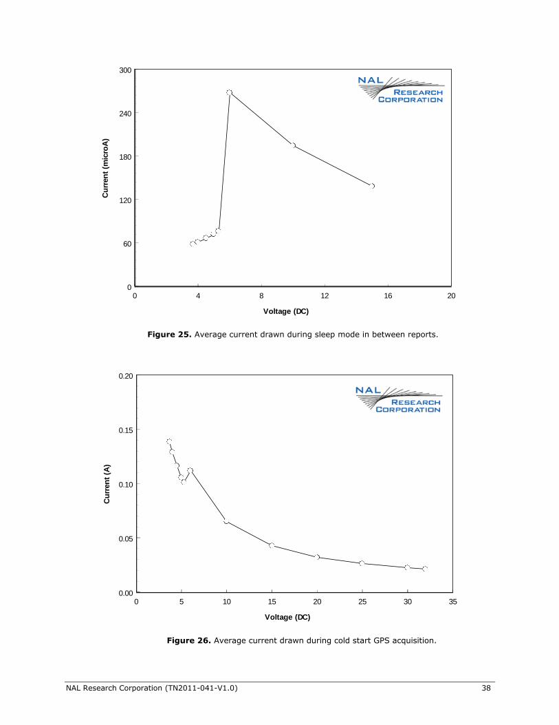
NAL Research Corporation (TN2011-041-V1.0) 38
0 5 10 15 20 25 30 35
Voltage (DC)
0.00
0.05
0.10
0.15
0.20
Cu
rren
t (A
)
Figure 26. Average current drawn during cold start GPS acquisition.
0 4 8 12 16 20
Voltage (DC)
0
60
120
180
240
300
Cu
rren
t (m
icro
A)
Figure 25. Average current drawn during sleep mode in between reports.
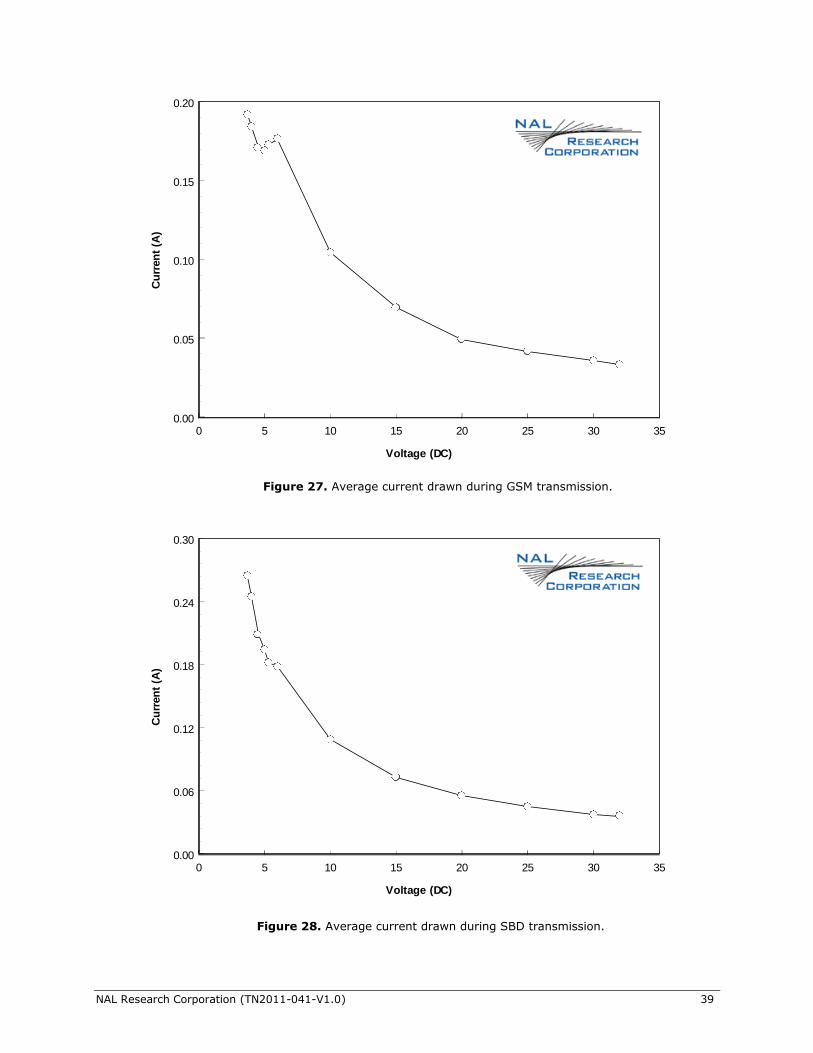
NAL Research Corporation (TN2011-041-V1.0) 39
Figure 28. Average current drawn during SBD transmission.
0 5 10 15 20 25 30 35
Voltage (DC)
0.00
0.06
0.12
0.18
0.24
0.30
Cu
rren
t (A
)
0 5 10 15 20 25 30 35
Voltage (DC)
0.00
0.05
0.10
0.15
0.20
Cu
rren
t (A
)
Figure 27. Average current drawn during GSM transmission.
NAL Research Corporation (TN2011-041-V1.0) 40
7.0 TECHNICAL SUPPORT
FOR TECHNICAL SUPPORT, PLEASE CONTACT US AT
Phone: 703-392-1136 FAX: 703-392-6795
E-mail: [email protected]
Technical documents are also available to download on NAL Research’s website www.nalresearch.com

NAL Research Corporation (TN2011-041-V1.0) 41
APPENDIX A: STANDARDS COMPLIANCE
The 9602 transceiver is designed to meet the regulatory requirements for approval for FCC, Canada,
and CE assuming an antenna with a gain of ~3 dBi and adequate shielding. The 9602 transceiver is tested to
the regulatory and technical certifications shown in table below.
Regulatory Approvals
Radio Tests EMC Tests Mechanical/ Electrical Tests
CE
FCC
Industry Canada
ETSI EN 301 441 V1.1.1 (2000-05)
FCC CFR47 Parts 2, 15, and 25
Industry Canada RSS170 Issue 1, Rev 1, November
6, 1999
ETSI EN 301 489-1 V1.8.1 (2008-04)
ETSI EN 301 489-20 V1.2.1 (2002-11)
EN61000-4-2: 1995/A2: 2001 Part 4.2
EN61000-4-3: 2002 Part 4.3
EN61000-4-4: 2004
EN61000-4-6: 1996/A1: 2001 Part 4.6
EN55022: 2006
EN60950-1:2006 Part 1
NAL Research Corporation (TN2011-041-V1.0) 42
APPENDIX B: EXPORT COMPLIANCE INFORMATION
The 9602-GSM is controlled by the export laws and regulations of the United States of America (U.S.). It
is the policy of NAL Research to fully comply with all U.S. export and economic sanction laws and
regulations. The export of NAL Research products, services, hardware, software and technology must be
made only in accordance with the laws, regulations and licensing requirements of the U.S. Government. NAL
Research customers must also comply with these laws and regulations. Failure to comply can result in the
imposition of fines and penalties, the loss of export privileges, and termination of your contractual
agreements with NAL Research.
The export and re-export of NAL Research products and services are subject to regulation by the Export
Administration Regulations (15 CFR 730-744), as administered by the U.S. Department of Commerce,
Bureau of Industry and Security (“BIS”). See: http://www.bxa.doc.gov for further information on BIS and
the Export Administration Regulations (EAR). Additional export restrictions are administered by the U.S.
Department of the Treasury’s Office of Foreign Asset Controls (“OFAC”). See: http://www.ustreas.gov/ofac
for further information on OFAC and its requirements.
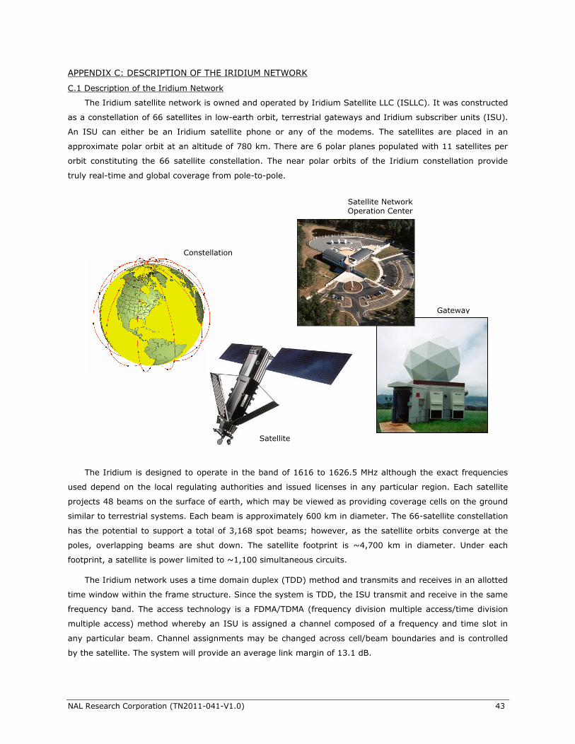
NAL Research Corporation (TN2011-041-V1.0) 43
APPENDIX C: DESCRIPTION OF THE IRIDIUM NETWORK
C.1 Description of the Iridium Network
The Iridium satellite network is owned and operated by Iridium Satellite LLC (ISLLC). It was constructed
as a constellation of 66 satellites in low-earth orbit, terrestrial gateways and Iridium subscriber units (ISU).
An ISU can either be an Iridium satellite phone or any of the modems. The satellites are placed in an
approximate polar orbit at an altitude of 780 km. There are 6 polar planes populated with 11 satellites per
orbit constituting the 66 satellite constellation. The near polar orbits of the Iridium constellation provide
truly real-time and global coverage from pole-to-pole.
The Iridium is designed to operate in the band of 1616 to 1626.5 MHz although the exact frequencies
used depend on the local regulating authorities and issued licenses in any particular region. Each satellite
projects 48 beams on the surface of earth, which may be viewed as providing coverage cells on the ground
similar to terrestrial systems. Each beam is approximately 600 km in diameter. The 66-satellite constellation
has the potential to support a total of 3,168 spot beams; however, as the satellite orbits converge at the
poles, overlapping beams are shut down. The satellite footprint is ~4,700 km in diameter. Under each
footprint, a satellite is power limited to ~1,100 simultaneous circuits.
The Iridium network uses a time domain duplex (TDD) method and transmits and receives in an allotted
time window within the frame structure. Since the system is TDD, the ISU transmit and receive in the same
frequency band. The access technology is a FDMA/TDMA (frequency division multiple access/time division
multiple access) method whereby an ISU is assigned a channel composed of a frequency and time slot in
any particular beam. Channel assignments may be changed across cell/beam boundaries and is controlled
by the satellite. The system will provide an average link margin of 13.1 dB.
Constellation
Satellite
Gateway
Satellite Network Operation Center
(SNOC)
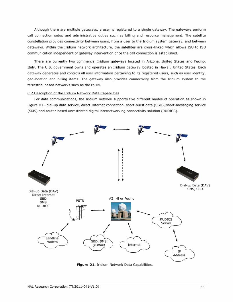
NAL Research Corporation (TN2011-041-V1.0) 44
Although there are multiple gateways, a user is registered to a single gateway. The gateways perform
call connection setup and administrative duties such as billing and resource management. The satellite
constellation provides connectivity between users, from a user to the Iridium system gateway, and between
gateways. Within the Iridium network architecture, the satellites are cross-linked which allows ISU to ISU
communication independent of gateway intervention once the call connection is established.
There are currently two commercial Iridium gateways located in Arizona, United States and Fucino,
Italy. The U.S. government owns and operates an Iridium gateway located in Hawaii, United States. Each
gateway generates and controls all user information pertaining to its registered users, such as user identity,
geo-location and billing items. The gateway also provides connectivity from the Iridium system to the
terrestrial based networks such as the PSTN.
C.2 Description of the Iridium Network Data Capabilities
For data communications, the Iridium network supports five different modes of operation as shown in
Figure D1—dial-up data service, direct Internet connection, short-burst data (SBD), short-messaging service
(SMS) and router-based unrestricted digital internetworking connectivity solution (RUDICS).
Dial-up Data (DAV) Direct Internet
SBD SMS
RUDICS
Dial-up Data (DAV) SMS, SBD
Internet
AZ, HI or Fucino
SBD, SMS (e-mail)
RUDICS Server
IP
Address
PSTN
Landline Modem
Figure D1. Iridium Network Data Capabilities.
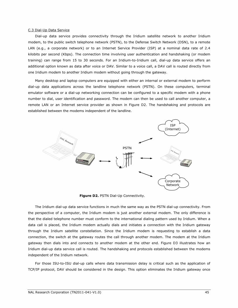
NAL Research Corporation (TN2011-041-V1.0) 45
C.3 Dial-Up Data Service
Dial-up data service provides connectivity through the Iridium satellite network to another Iridium
modem, to the public switch telephone network (PSTN), to the Defense Switch Network (DSN), to a remote
LAN (e.g., a corporate network) or to an Internet Service Provider (ISP) at a nominal data rate of 2.4
kilobits per second (Kbps). The connection time involving user authentication and handshaking (or modem
training) can range from 15 to 30 seconds. For an Iridium-to-Iridium call, dial-up data service offers an
additional option known as data after voice or DAV. Similar to a voice call, a DAV call is routed directly from
one Iridium modem to another Iridium modem without going through the gateway.
Many desktop and laptop computers are equipped with either an internal or external modem to perform
dial-up data applications across the landline telephone network (PSTN). On these computers, terminal
emulator software or a dial-up networking connection can be configured to a specific modem with a phone
number to dial, user identification and password. The modem can then be used to call another computer, a
remote LAN or an Internet service provider as shown in Figure D2. The handshaking and protocols are
established between the modems independent of the landline.
The Iridium dial-up data service functions in much the same way as the PSTN dial-up connectivity. From
the perspective of a computer, the Iridium modem is just another external modem. The only difference is
that the dialed telephone number must conform to the international dialing pattern used by Iridium. When a
data call is placed, the Iridium modem actually dials and initiates a connection with the Iridium gateway
through the Iridium satellite constellation. Since the Iridium modem is requesting to establish a data
connection, the switch at the gateway routes the call through another modem. The modem at the Iridium
gateway then dials into and connects to another modem at the other end. Figure D3 illustrates how an
Iridium dial-up data service call is routed. The handshaking and protocols established between the modems
independent of the Iridium network.
For those ISU-to-ISU dial-up calls where data transmission delay is critical such as the application of
TCP/IP protocol, DAV should be considered in the design. This option eliminates the Iridium gateway once
Figure D2. PSTN Dial-Up Connectivity.
4.4 VDC
RS232
NAL Research
Antenna
PSTN
ISP
(Internet)
Corporate Network
4.4 VDC
RS232
NAL Research
Antenna
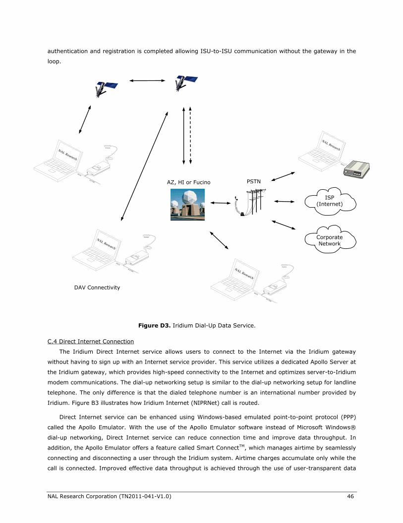
NAL Research Corporation (TN2011-041-V1.0) 46
authentication and registration is completed allowing ISU-to-ISU communication without the gateway in the
loop.
C.4 Direct Internet Connection
The Iridium Direct Internet service allows users to connect to the Internet via the Iridium gateway
without having to sign up with an Internet service provider. This service utilizes a dedicated Apollo Server at
the Iridium gateway, which provides high-speed connectivity to the Internet and optimizes server-to-Iridium
modem communications. The dial-up networking setup is similar to the dial-up networking setup for landline
telephone. The only difference is that the dialed telephone number is an international number provided by
Iridium. Figure B3 illustrates how Iridium Internet (NIPRNet) call is routed.
Direct Internet service can be enhanced using Windows-based emulated point-to-point protocol (PPP)
called the Apollo Emulator. With the use of the Apollo Emulator software instead of Microsoft Windows®
dial-up networking, Direct Internet service can reduce connection time and improve data throughput. In
addition, the Apollo Emulator offers a feature called Smart ConnectTM, which manages airtime by seamlessly
connecting and disconnecting a user through the Iridium system. Airtime charges accumulate only while the
call is connected. Improved effective data throughput is achieved through the use of user-transparent data
Figure D3. Iridium Dial-Up Data Service.
4.4 VDC
RS232
NAL Research
Antenna
PSTN
ISP
(Internet)
Corporate Network
4.4 VDC
RS232
NAL Research
Antenna
4.4 VDC
RS232
NAL Research
Antenna
AZ, HI or Fucino
4.4 VDC
RS232
NAL Research
Antenna
DAV Connectivity
NAL Research Corporation (TN2011-041-V1.0) 47
compression. The channel rate is still 2.4 Kbps. However, 10 Kbps effective throughput can be achieved
depending on content (graphics and images will result in lower effective throughput).
C.5 Short-Burst Data (SBD)
SBD is a simple and efficient bi-directional transport capability used to transfer messages with sizes
ranging from zero (a mailbox check) to 1960 bytes. SBD takes advantage of signals within the existing air
interface, without using the dedicated traffic channels. As a result, small amounts of data can be transferred
more efficiently than those associated with circuit-switched data calls. Messages that originate from an
Iridium modem can be delivered to a variety of destinations. Commonly, data are delivered across terrestrial
communications networks (NIPRnet and Internet) to servers and applications that process data from one or
multiple fielded Iridium modems. SBD service also supports the transfer of messages to Iridium modems,
where messages may originate from terrestrial sources. Delivery methods and options are initially
configured when the Iridium modem is first purchased and may be easily modified via web pages at a later
time.
C.6 Short Messaging Service (SMS)
SMS is a mechanism to deliver short data messages over the Iridium satellite network to the
NIPRNet/Internet. Iridium SMS service incorporates a subset of the GSM SMS features. Each SMS message
can be up to 160 text characters (7-bit coded) in length. The text characters are based on a 7-bit alphabet,
which is encoded and transmitted as 8-bit data, hence the 140 octet (byte) maximum message size.
SMS service is a store and forward method of transmitting messages to and from an Iridium modem.
The short message from the modem is stored in a central Short Message Center (SMSC) which then
forwards it to the destination. In the case that the recipient is not available, the SMSC will attempt to deliver
the SMS until it is delivered or the validity period expires. SMS supports a limited confirmation of message
delivery. The sender of the short message can request to receive a return message notifying them whether
the short message has been delivered or not. With this option, the originator gets a confirmation that the
message was delivered to the SMSC. Unlike standard GSM, the Iridium SMS can only acknowledge that the
message was delivered to the SMSC and not the end-destination.
SMS messages can be sent and received simultaneously while a voice call is in progress. This is possible
because SMS messages travel over and above the radio channel using the signaling path, whereas the voice
call uses a dedicated “traffic” radio channel for the duration of the call.
C.7 RUDICS
RUDICS is an enhanced gateway termination and origination capability for circuit switched data calls
across the Iridium satellite network. When an Iridium modem places a call to the RUDICS Server located at
the Iridium Gateway, the RUDICS Server connects the call to a pre-defined IP address allowing an end-to-
end IP connection between the Host Application and the Iridium modem. There are three key benefits of
using RUDICS over the conventional PSTN circuit switched data connectivity or mobile-to-mobile data
solutions: (1) elimination of analog modem training time, (2) increased call connection quality, reliability,
and maximized throughput and (3) protocol independence.
NAL Research Corporation (TN2011-041-V1.0) 48
C.8 Iridium Geo-Location
The Iridium network makes calculations of the geographical location (geo-location) of an ISU each time
a call is placed. The technique employed to determine the geo-location of an ISU is based on measurements
of the ISU and satellite propagation delay and Doppler frequency shift. These measurements are used to
estimate cosines of spherical angles that identify the ISU’s location relative to the satellite by the gateway.
The Iridium network can locate an ISU to within 10 km only about 78% of the time. The so-called error
ellipse can have a large eccentricity with the major axis oriented in the azimuth dimension and the minor
axis oriented in the radial dimension. The position of the ISU in the radial dimension relative to the satellite
can almost always be determined to within 10 km with just one measurement. Errors in the azimuth
dimension relative to the satellite are largest along the satellite’s ground path and tend to increase with
distance from the satellite. Geo-location errors in the east-west dimension, therefore, are sometimes more
than 100 times greater than in the north-south dimension.