Embed Size (px)
Citation preview
9602 SBD Modem Short Burst Data Modem
Installation & User Manual
Beam Communications Pty Ltd
www.beamcommunications.com
www.beamcommunications.com2 9602 SBD Modem | Installation and User Manual
9602 SBD ModemInstallation and User Manual
GLOBAL HEAD OFFICE8 Anzed Court
Mulgrave, Victoria, Australia, 3170
Information furnished by Beam Communications Pty Ltd (Beam) is believed to be accurate and reliable. However, no responsibility is assumed by Beam for its use, or for any infringement of patents or other rights of third parties, which may result from its use. No license is granted by
implication or otherwise under any patent or patent rights of Beam. Beam reserves the right to change specifications at any time without notice.
Copyright © 2011 Beam Communications Pty Ltd. All rights reserved
Product name: 9602 SBD Modem Installation & User Manual
Manual revision: 01
Part Number USRMAN007501
Issue Date: November 2011
www.beamcommunications.com9602 SBD Modem | Installation and User Manual 3
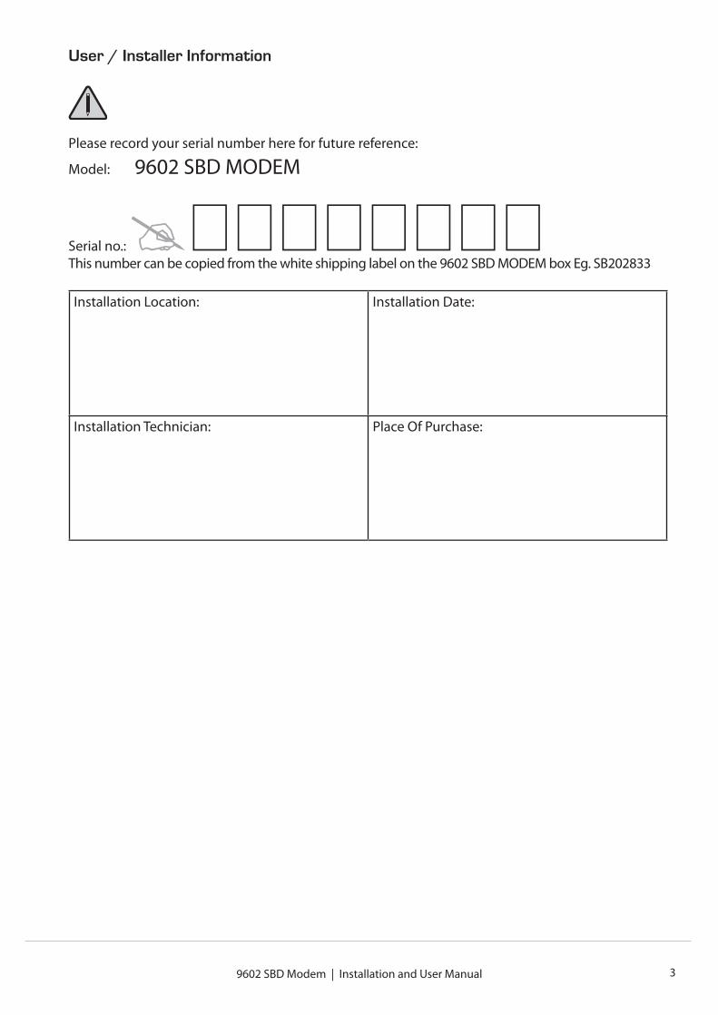
User / Installer Information
Please record your serial number here for future reference:
Model: 9602 SBD MODEM
Serial no.: This number can be copied from the white shipping label on the 9602 SBD MODEM box Eg. SB202833
Installation Location: Installation Date:
Installation Technician: Place Of Purchase:
www.beamcommunications.com4
Content
User / Installer Information 3Equipment Overview 5About BEAM Communications 6Conventions in this Manual 7Safety Information 7What is the 9602 SBD Modem? 8Package Contents 8Optional BEAM Accessories 8Installing the 9602 SBD Modem 9Connecting the antenna cable 9Connecting the power and IO cables and USB cable 10How to Mount the 9602 SBD Modem 11Installing the USB Drivers 12Dimensions 15Specification Summary 16RS232 Specification 17Physical Connection 17RS232 Port signal support and handshaking 17RS232 port electrical parameters 19Data Connectivity 19Configuration Settings 19Modes of Operation 20Hardware failure reporting 20RF Interface 21Antenna Connector 21Antenna Connector Type 21Radio Characteristics 21Troubleshooting the 9602 SBD Modem 22BEAM Warranty conditions 23
9602 SBD Modem | Installation and User Manual 5
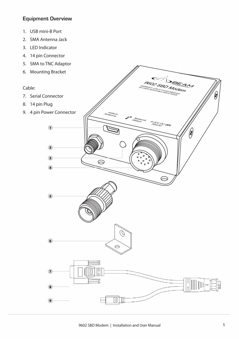
Equipment Overview
1. USB mini-B Port
2. SMA Antenna Jack
3. LED Indicator
4. 14 pin Connector
5. SMA to TNC Adaptor
6. Mounting Bracket
Cable:
7. Serial Connector
8. 14 pin Plug
9. 4 pin Power Connector
1
2
3
4
5
7
6
8
9

www.beamcommunications.com6
About BEAM Communications
BEAM Communications, a wholly owned subsidiary of World Reach Limited (WRR), listed on the Australian Stock Exchange, is a world leader in design, manufacture and distribution of specialized communications equipment for the Iridium Satellite Network.
BEAM’s commitment to be at the forefront has continued to increase its share of the global satellite communications market. Its premium distribution network spans the world.
Recognized as a leading provider of satellite communication solutions, BEAM specializes in Voice, Data, Tracking and customized solutions. BEAM develops innovative products and services to meet market demands and niche applications.
BEAM’s leading edge products are deployed in a wide range of markets including Maritime, Transport, Government, Defence, Mining, Construction, Forestry, Emergency Services, Relief Aid, Telemetry and Rural Telephony.
Supported by a dedicated team of professionals, BEAM has developed solid relationships with its peers and network of distributors worldwide.
Beam Communications Pty Ltd
8 Anzed Court, Mulgrave,
Victoria, 3170, AUSTRALIA
Web: www.beamcommunications.com
Info: [email protected]
Support: [email protected]
Tel: +61 3 8588 4500
Fax: +61 3 9560 9055
9602 SBD Modem | Installation and User Manual 7
Conventions in this Manual
Warnings, cautions and notes appear throughout this manual.
They are represented by following conventions.
Warning: This symbol and associated text indicate a warning note providing information to prevent personal injury or damage to equipment. Note: This symbol and associated text indicate a note providing general operating information. Interference: All wireless phones may get interference, which could affect performance.
Safety Information
Note: Read the following information before installing and using the BEAM 9602 SBD Modem.
Your 9602 SBD Modem is a low power radio transmitter and receiver. When it is ON, it receives and sends out radio frequency (RF) signals.
The design of your 9602 SBD MODEM system complies with international safety standards.
Refer to the appropriate section of the 9602 SBD MODEM User Manual for additional relevant safety information.
Warning: Do not open equipment. There are no user-serviceable parts inside.If a DC power supply is to be used, its output must comply with the Safety Extra Low Voltage (SELV) requirements of IEC60950.All connectors must only be connected to equipment ports which comply with the Safety Extra Low Voltage (SELV) requirements of IEC60950.”
www.beamcommunications.com8 9602 SBD Modem | Installation and User Manual
What is the 9602 SBD Modem?
The 9602 SBD MODEM is a Remote Satellite Short Burst Data only modem designed to provide a reliable and cost effective means of Iridium SBD development.
It utilizes the Iridium SBD (Short Burst Data) module and provides both D9 RS232 and USB Mini-B connectors, for direct connection to a PC.
Key Features:
• Small form Factor
• No SIM Card Required
• Maximum mobile originated message size of 340 bytes
• Maximum mobile terminated message size of 270 bytes
• Visual indication of network availability
Package Contents
The 9602 SBD MODEM package contains:
• 1 x 9602 SBD MODEM Short Burst Data Modem
• 1 x Mounting L Bracket with attaching screw
• 1 x Power & IO Cable [CBLASY014604*]
• 1 x DC External Cable [CBLASY008003*]
• 1 x 2m USB Cable [CBLASY006701*]
• 1 x TNC-F to SMA-M coaxial adaptor [TNCF-SMAM]
• SBD9602 Quick Start Guide [USRQSG007501*]
• 1 x Resources CD (includes User Manual) [CDROM000401*]
* The last 2 digits of the part number indicate the revision. A higher number may be supplied
Optional Beam Accessories
RST710 Fixed Mast Antenna
RST715 Magnetic Mount Antenna
RST720 Bolt Mount Antenna
RST985 Serial to USB Converter Cable
See your Service Provider for pricing and availability of these optional accessories
www.beamcommunications.com9602 SBD Modem | Installation and User Manual 9
Installing the 9602 SBD MODEM
Connecting the Antenna Cable
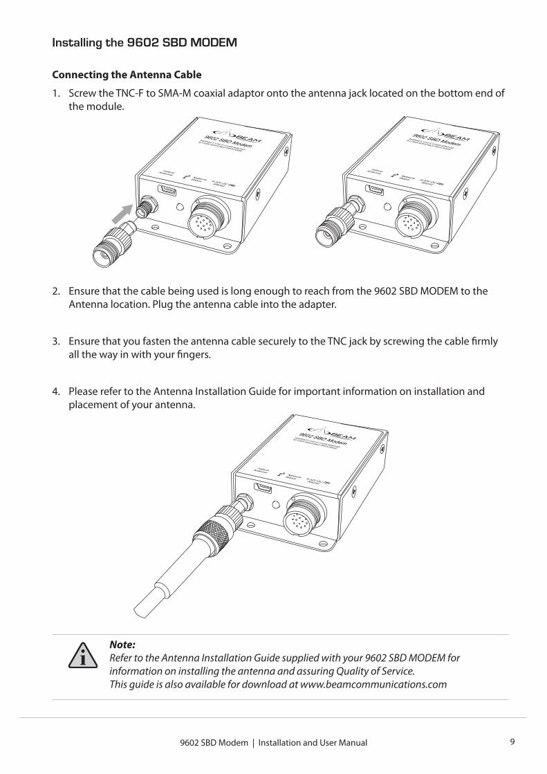
1. Screw the TNC-F to SMA-M coaxial adaptor onto the antenna jack located on the bottom end of the module.
2. Ensure that the cable being used is long enough to reach from the 9602 SBD MODEM to the Antenna location. Plug the antenna cable into the adapter.
3. Ensure that you fasten the antenna cable securely to the TNC jack by screwing the cable firmly all the way in with your fingers.
4. Please refer to the Antenna Installation Guide for important information on installation and placement of your antenna.
Note: Refer to the Antenna Installation Guide supplied with your 9602 SBD MODEM for information on installing the antenna and assuring Quality of Service.This guide is also available for download at www.beamcommunications.com
www.beamcommunications.com10
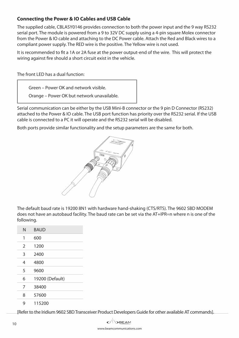
Connecting the Power & IO Cables and USB CableThe supplied cable, CBLASY0146 provides connection to both the power input and the 9 way RS232 serial port. The module is powered from a 9 to 32V DC supply using a 4-pin square Molex connector from the Power & IO cable and attaching to the DC Power cable. Attach the Red and Black wires to a compliant power supply. The RED wire is the positive. The Yellow wire is not used.
It is recommended to fit a 1A or 2A fuse at the power output-end of the wire. This will protect the wiring against fire should a short circuit exist in the vehicle.
The front LED has a dual function:
Green – Power OK and network visible.
Orange – Power OK but network unavailable.
Serial communication can be either by the USB Mini-B connector or the 9 pin D Connector (RS232) attached to the Power & IO cable. The USB port function has priority over the RS232 serial. If the USB cable is connected to a PC it will operate and the RS232 serial will be disabled.
Both ports provide similar functionality and the setup parameters are the same for both.
The default baud rate is 19200 8N1 with hardware hand-shaking (CTS/RTS). The 9602 SBD MODEM does not have an autobaud facility. The baud rate can be set via the AT+IPR=n where n is one of the following.
N BAUD
1 600
2 1200
3 2400
4 4800
5 9600
6 19200 (Default)
7 38400
8 57600
9 115200
[Refer to the Iridium 9602 SBD Transceiver Product Developers Guide for other available AT commands].
9602 SBD Modem | Installation and User Manual 11
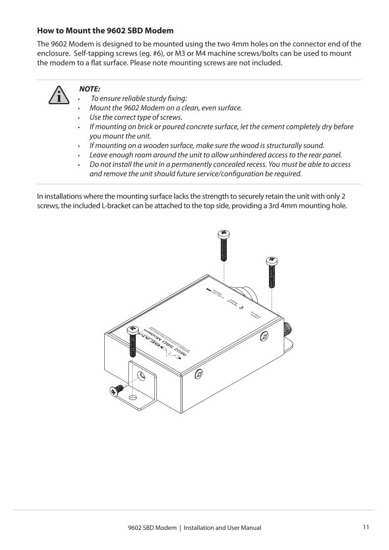
How to Mount the 9602 SBD ModemThe 9602 Modem is designed to be mounted using the two 4mm holes on the connector end of the enclosure. Self-tapping screws (eg. #6), or M3 or M4 machine screws/bolts can be used to mount the modem to a flat surface. Please note mounting screws are not included.
NOTE: • To ensure reliable sturdy fixing:• Mount the 9602 Modem on a clean, even surface.• Use the correct type of screws. • If mounting on brick or poured concrete surface, let the cement completely dry before
you mount the unit. • If mounting on a wooden surface, make sure the wood is structurally sound.• Leave enough room around the unit to allow unhindered access to the rear panel. • Do not install the unit in a permanently concealed recess. You must be able to access
and remove the unit should future service/configuration be required.
In installations where the mounting surface lacks the strength to securely retain the unit with only 2 screws, the included L-bracket can be attached to the top side, providing a 3rd 4mm mounting hole.
www.beamcommunications.com12 9602 SBD Modem | Installation and User Manual
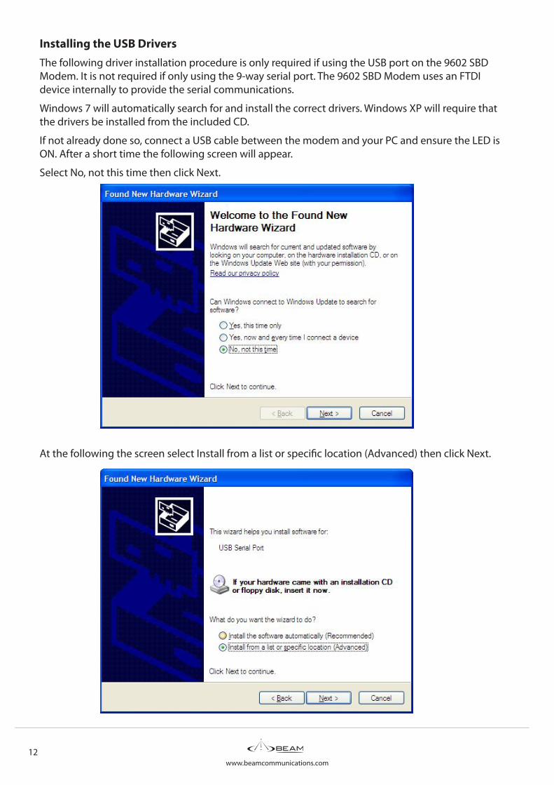
Installing the USB DriversThe following driver installation procedure is only required if using the USB port on the 9602 SBD Modem. It is not required if only using the 9-way serial port. The 9602 SBD Modem uses an FTDI device internally to provide the serial communications.
Windows 7 will automatically search for and install the correct drivers. Windows XP will require that the drivers be installed from the included CD.
If not already done so, connect a USB cable between the modem and your PC and ensure the LED is ON. After a short time the following screen will appear.
Select No, not this time then click Next.
At the following the screen select Install from a list or specific location (Advanced) then click Next.
www.beamcommunications.com9602 SBD Modem | Installation and User Manual 13
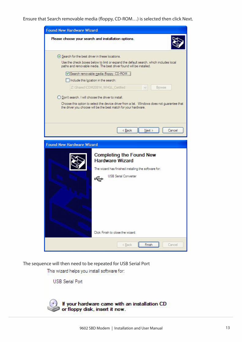
Ensure that Search removable media (floppy, CD-ROM…) is selected then click Next.
The sequence will then need to be repeated for USB Serial Port
www.beamcommunications.com14 9602 SBD Modem | Installation and User Manual
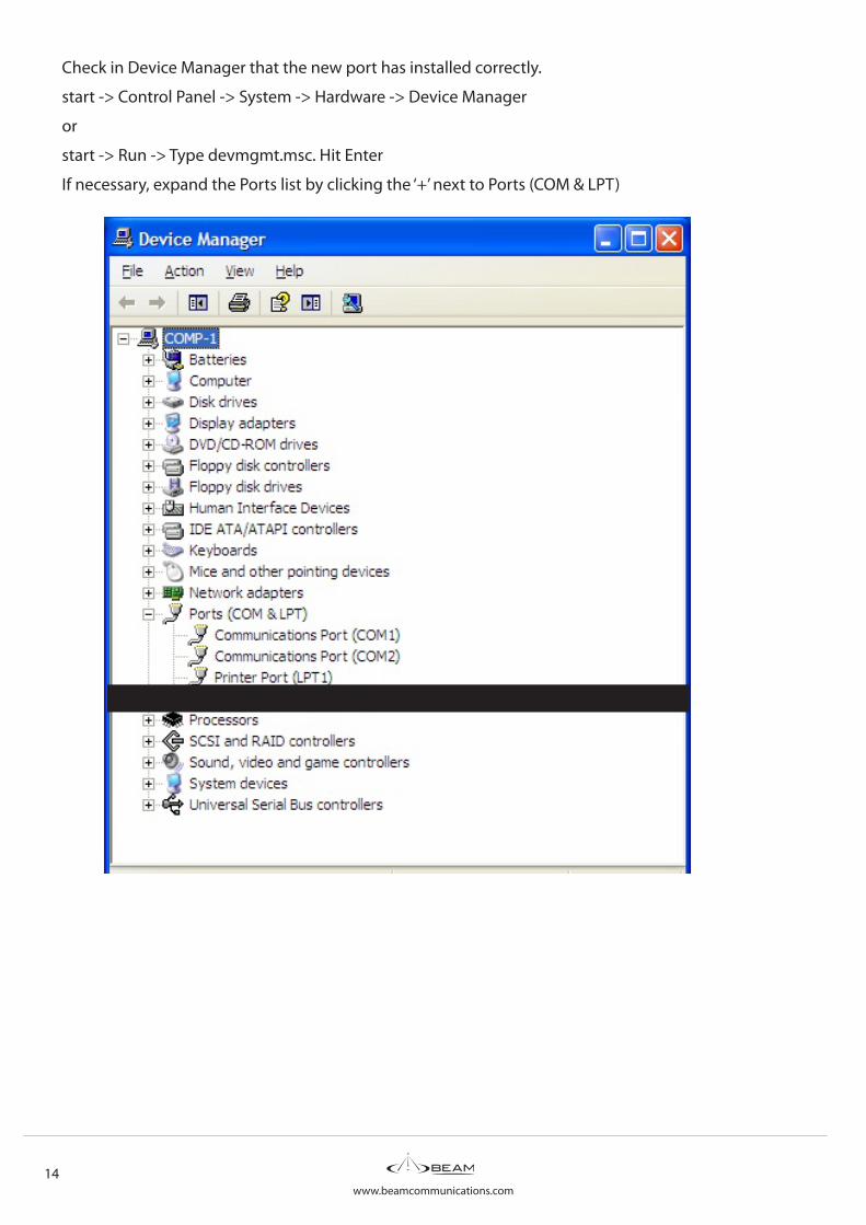
Check in Device Manager that the new port has installed correctly.
start -> Control Panel -> System -> Hardware -> Device Manager
or
start -> Run -> Type devmgmt.msc. Hit Enter
If necessary, expand the Ports list by clicking the ‘+’ next to Ports (COM & LPT)
www.beamcommunications.com9602 SBD Modem | Installation and User Manual 15
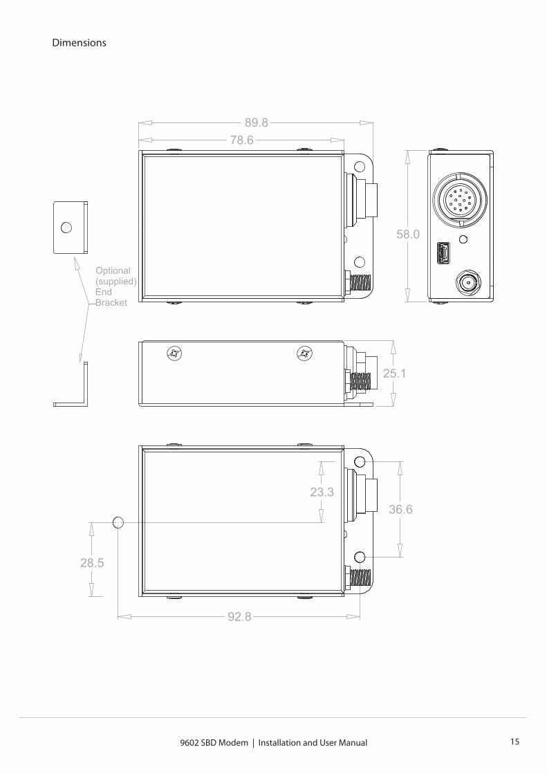
Dimensions
36.6
92.8
23.3
28.5
78.689.8
25.1
58.0
Optional (supplied) End Bracket
www.beamcommunications.com16 9602 SBD Modem | Installation and User Manual
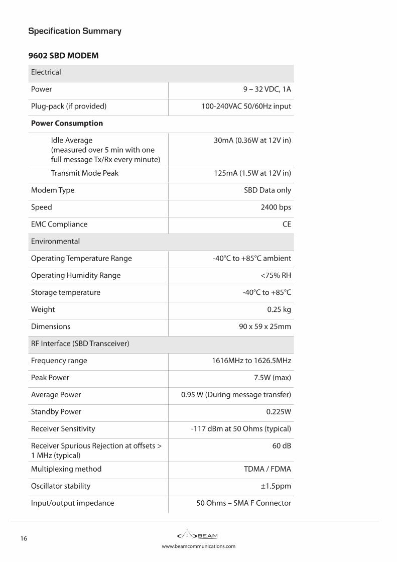
Specification Summary
9602 SBD MODEM
Electrical
Power 9 – 32 VDC, 1A
Plug-pack (if provided) 100-240VAC 50/60Hz input
Power Consumption
Idle Average (measured over 5 min with one full message Tx/Rx every minute)
30mA (0.36W at 12V in)
Transmit Mode Peak 125mA (1.5W at 12V in)
Modem Type SBD Data only
Speed 2400 bps
EMC Compliance CE
Environmental
Operating Temperature Range -40°C to +85°C ambient
Operating Humidity Range <75% RH
Storage temperature -40°C to +85°C
Weight 0.25 kg
Dimensions 90 x 59 x 25mm
RF Interface (SBD Transceiver)
Frequency range 1616MHz to 1626.5MHz
Peak Power 7.5W (max)
Average Power 0.95 W (During message transfer)
Standby Power 0.225W
Receiver Sensitivity -117 dBm at 50 Ohms (typical)
Receiver Spurious Rejection at offsets > 1 MHz (typical)
60 dB
Multiplexing method TDMA / FDMA
Oscillator stability ±1.5ppm
Input/output impedance 50 Ohms – SMA F Connector
www.beamcommunications.com9602 SBD Modem | Installation and User Manual 17
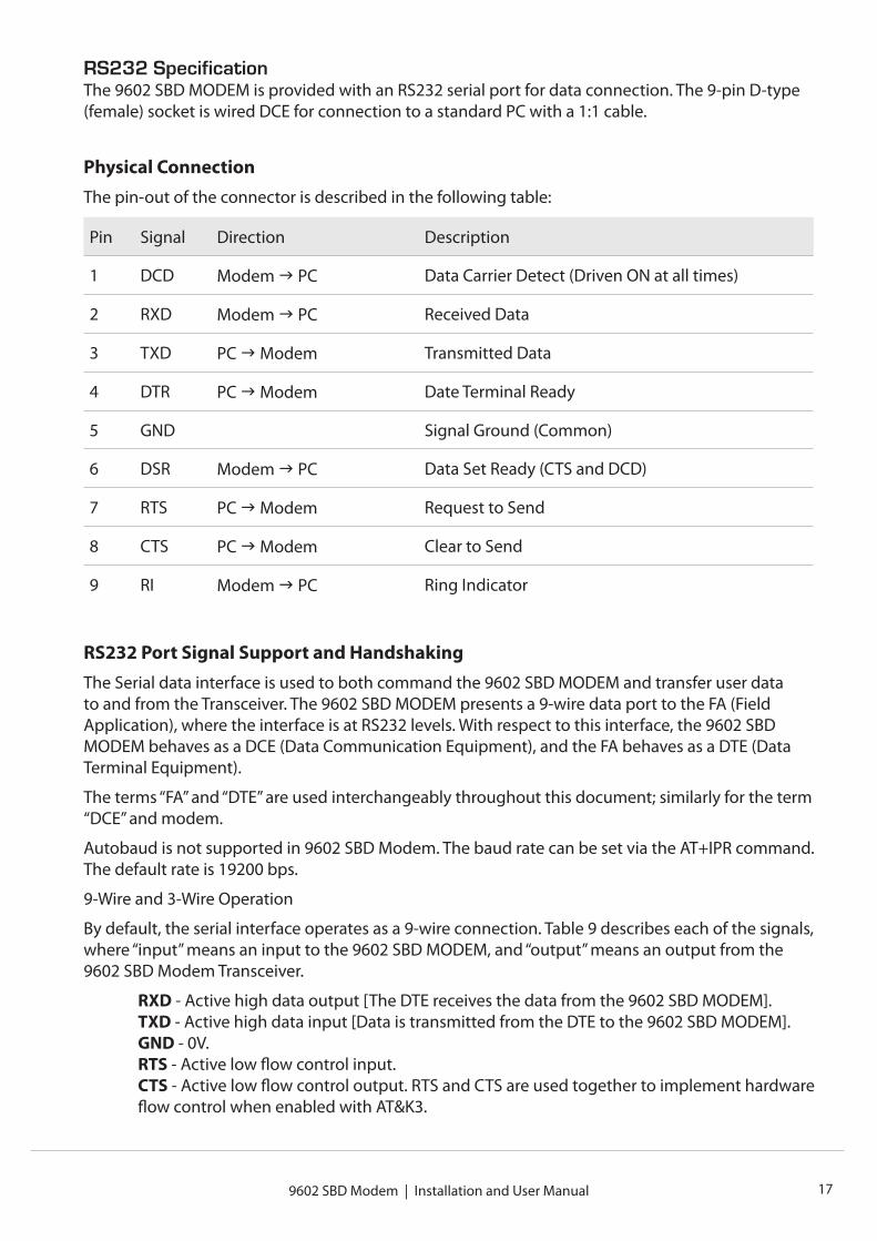
RS232 SpecificationThe 9602 SBD MODEM is provided with an RS232 serial port for data connection. The 9-pin D-type (female) socket is wired DCE for connection to a standard PC with a 1:1 cable.
Physical ConnectionThe pin-out of the connector is described in the following table:
Pin Signal Direction Description
1 DCD Modem PC Data Carrier Detect (Driven ON at all times)
2 RXD Modem PC Received Data
3 TXD PC Modem Transmitted Data
4 DTR PC Modem Date Terminal Ready
5 GND Signal Ground (Common)
6 DSR Modem PC Data Set Ready (CTS and DCD)
7 RTS PC Modem Request to Send
8 CTS PC Modem Clear to Send
9 RI Modem PC Ring Indicator
RS232 Port Signal Support and HandshakingThe Serial data interface is used to both command the 9602 SBD MODEM and transfer user data to and from the Transceiver. The 9602 SBD MODEM presents a 9-wire data port to the FA (Field Application), where the interface is at RS232 levels. With respect to this interface, the 9602 SBD MODEM behaves as a DCE (Data Communication Equipment), and the FA behaves as a DTE (Data Terminal Equipment).
The terms “FA” and “DTE” are used interchangeably throughout this document; similarly for the term “DCE” and modem.
Autobaud is not supported in 9602 SBD Modem. The baud rate can be set via the AT+IPR command. The default rate is 19200 bps.
9-Wire and 3-Wire Operation
By default, the serial interface operates as a 9-wire connection. Table 9 describes each of the signals, where “input” means an input to the 9602 SBD MODEM, and “output” means an output from the 9602 SBD Modem Transceiver.
RXD - Active high data output [The DTE receives the data from the 9602 SBD MODEM].TXD - Active high data input [Data is transmitted from the DTE to the 9602 SBD MODEM].GND - 0V.RTS - Active low flow control input.CTS - Active low flow control output. RTS and CTS are used together to implement hardware flow control when enabled with AT&K3.
www.beamcommunications.com18 9602 SBD Modem | Installation and User Manual
DTR - Active low handshaking input AT&Dn controls how the 9602 SBD MODEM uses DTR:If set to AT&D0, DTR is always ignored. Otherwise DTR set to OFF places the data port into UART test mode after 10 seconds, or immediately on bootup. A subsequent transition of DTR to ON returns the data port to DCE mode and resets it to its power-on state.The UART test mode is provided for factory testing of the data port UART. An FA should never activate test mode; if it does, the 9602 SBD MODEM will stop responding to AT commands until the data port is returned to DCE mode.DSR - Active low handshaking output.The 9602 SBD MODEM drives DSR ON when the data port is in DCE mode, and OFF when the data port is in test mode. The DTE may use this signal as an indication that the 9602 SBD MODEM is powered up and ready to receive AT commands.RI - Active low ring indicator output.The 9602 SBD MODEM drives RI ON when it receives a AutomaticNotification from the network that a Mobile Terminated SBD Message is queued at the Gateway, and drives RI OFF after 5 seconds or when the DTE initiates an SBD session, whichever occurs first.DCD - Active low handshaking output.DCD is driven OFF at all times.
Note: The Ring Indicator (RI) pin is used by the 9602 SBD MODEM SBD Transceiver to indicate that a Mobile Terminated SBD (MT-SBD) message is queued at the Gateway. The Field Application can monitor this pin and use appropriate AT Commands to command the Transceiver to retrieve the MT-SBD message.
The serial interface may be operated with a 3-wire connection, where only transmit, receive and ground signals are used. However the 9 wire interface offers better control and is the recommended implementation. Iridium is only able to provide limited 3-wire interface support. When operating with a 3-wire connection, the following rules apply:
• AT&Dn must be set to AT&D0 to ignore the DTR input
• AT&Kn must be set to AT&K0 to disable RTS/CTS flow control
• The other output signals may be connected, and operate as follows:
x CTS driven ON (low) x DSR operates as normal x RI operates as normal x DCD driven ON (low)
Note: RTS/CTS flow control, when enabled, is only used when the data port is in SBD data mode. In AT command mode, RTS is ignored and CTS is driven ON (low).
www.beamcommunications.com9602 SBD Modem | Installation and User Manual 19
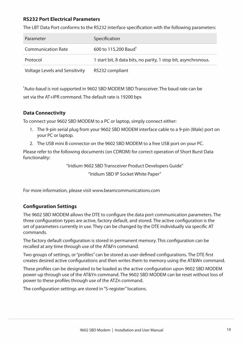
RS232 Port Electrical ParametersThe LBT Data Port conforms to the RS232 interface specification with the following parameters:
Parameter Specification
Communication Rate 600 to 115,200 Baud1
Protocol 1 start bit, 8 data bits, no parity, 1 stop bit, asynchronous.
Voltage Levels and Sensitivity RS232 compliant
1Auto-baud is not supported in 9602 SBD MODEM SBD Transceiver. The baud rate can be
set via the AT+IPR command. The default rate is 19200 bps
Data ConnectivityTo connect your 9602 SBD MODEM to a PC or laptop, simply connect either:
1. The 9-pin serial plug from your 9602 SBD MODEM interface cable to a 9-pin (Male) port on your PC or laptop.
2. The USB mini B connector on the 9602 SBD MODEM to a free USB port on your PC.
Please refer to the following documents (on CDROM) for correct operation of Short Burst Data functionality:
“Iridium 9602 SBD Transceiver Product Developers Guide”
“Iridium SBD IP Socket White Paper”
For more information, please visit www.beamcommunications.com
Configuration SettingsThe 9602 SBD MODEM allows the DTE to configure the data port communication parameters. The three configuration types are active, factory default, and stored. The active configuration is the set of parameters currently in use. They can be changed by the DTE individually via specific AT commands.
The factory default configuration is stored in permanent memory. This configuration can be recalled at any time through use of the AT&Fn command.
Two groups of settings, or “profiles” can be stored as user-defined configurations. The DTE first creates desired active configurations and then writes them to memory using the AT&Wn command.
These profiles can be designated to be loaded as the active configuration upon 9602 SBD MODEM power-up through use of the AT&Yn command. The 9602 SBD MODEM can be reset without loss of power to these profiles through use of the ATZn command.
The configuration settings are stored in “S-register” locations.
www.beamcommunications.com20 9602 SBD Modem | Installation and User Manual
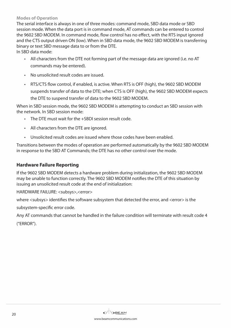
Modes of OperationThe serial interface is always in one of three modes: command mode, SBD data mode or SBD session mode. When the data port is in command mode, AT commands can be entered to control the 9602 SBD MODEM. In command mode, flow control has no effect, with the RTS input ignored and the CTS output driven ON (low). When in SBD data mode, the 9602 SBD MODEM is transferring binary or text SBD message data to or from the DTE.In SBD data mode:
• All characters from the DTE not forming part of the message data are ignored (i.e. no AT commands may be entered).
• No unsolicited result codes are issued.
• RTS/CTS flow control, if enabled, is active. When RTS is OFF (high), the 9602 SBD MODEM suspends transfer of data to the DTE; when CTS is OFF (high), the 9602 SBD MODEM expects the DTE to suspend transfer of data to the 9602 SBD MODEM.
When in SBD session mode, the 9602 SBD MODEM is attempting to conduct an SBD session with the network. In SBD session mode:
• The DTE must wait for the +SBDI session result code.
• All characters from the DTE are ignored.
• Unsolicited result codes are issued where those codes have been enabled.
Transitions between the modes of operation are performed automatically by the 9602 SBD MODEM in response to the SBD AT Commands; the DTE has no other control over the mode.
Hardware Failure ReportingIf the 9602 SBD MODEM detects a hardware problem during initialization, the 9602 SBD MODEM may be unable to function correctly. The 9602 SBD MODEM notifies the DTE of this situation by issuing an unsolicited result code at the end of initialization:
HARDWARE FAILURE: <subsys>,<error>
where <subsys> identifies the software subsystem that detected the error, and <error> is the
subsystem-specific error code.
Any AT commands that cannot be handled in the failure condition will terminate with result code 4
(“ERROR”).
www.beamcommunications.com9602 SBD Modem | Installation and User Manual 21
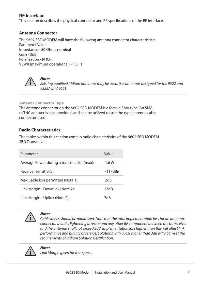
RF InterfaceThis section describes the physical connector and RF specifications of the RF Interface.
Antenna ConnectorThe 9602 SBD MODEM will have the following antenna connector characteristics:Parameter ValueImpedance - 50 Ohms nominalGain - 3dBiPolarization - RHCPVSWR (maximum operational) - 1.5 : 1
Note: Existing qualified Iridium antennas may be used. (i.e. antennas designed for the 9522 and 9522A and 9601)
Antenna Connector TypeThe antenna connector on the 9602 SBD MODEM is a female SMA type. An SMAto TNC adapter is also provided, and can be utilized to suit the type antenna cableconnector used.
Radio CharacteristicsThe tables within this section contain radio characteristics of the 9602 SBD MODEMSBD Transceiver.
Parameter Value
Average Power during a transmit slot (max): 1.6 W
Receiver sensitivity: -117dBm
Max Cable loss permitted (Note 1): 2dB
Link Margin –Downlink (Note 2): 13dB
Link Margin –Uplink (Note 2): 7dB
Note:Cable losses should be minimized. Note that the total implementation loss for an antenna, connectors, cable, lightening arrestor and any other RF component between the transceiver and the antenna shall not exceed 3dB. Implementation loss higher than this will affect link performance and quality of service. Solutions with a loss higher than 3dB will not meet the requirements of Iridium Solution Certification.
Note:Link Margin given for free space.
www.beamcommunications.com22 9602 SBD Modem | Installation and User Manual
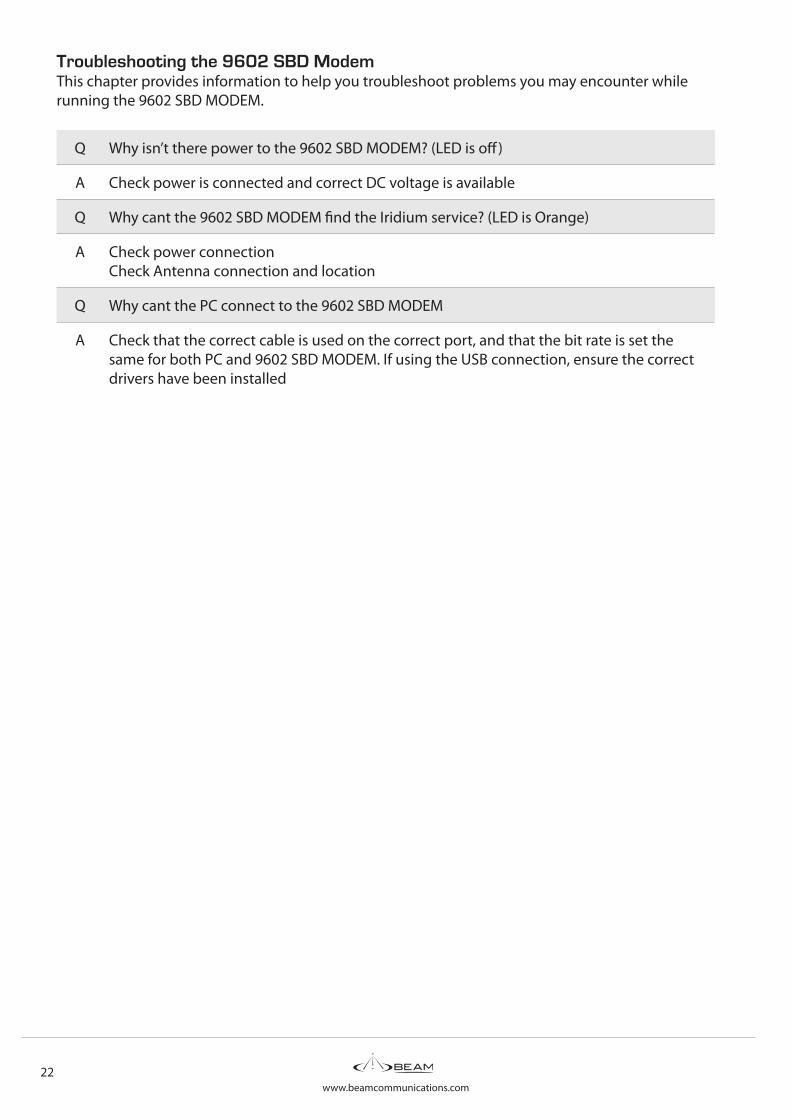
Troubleshooting the 9602 SBD ModemThis chapter provides information to help you troubleshoot problems you may encounter while running the 9602 SBD MODEM.
Q Why isn’t there power to the 9602 SBD MODEM? (LED is off)
A Check power is connected and correct DC voltage is available
Q Why cant the 9602 SBD MODEM find the Iridium service? (LED is Orange)
A Check power connectionCheck Antenna connection and location
Q Why cant the PC connect to the 9602 SBD MODEM
A Check that the correct cable is used on the correct port, and that the bit rate is set the same for both PC and 9602 SBD MODEM. If using the USB connection, ensure the correct drivers have been installed
www.beamcommunications.com9602 SBD Modem | Installation and User Manual 23
Beam Warranty Conditions
Beam Communications gives this express warranty (along with extended warranty endorsements, where applicable) in lieu of all other warranties, express or implied, including (without limitation), warranties of merchantability and fitness for a particular purpose. This constitutes our sole warranty and obligation with regard to our products as well as the Customer’s sole remedy.Beam Communications expressly disclaims all liability and responsibility for any special, indirect or consequential damages or any further loss of any kind whatsoever resulting from the use of our product(s). The Customer’s sole and exclusive remedy and the limit of Beam’s liability for any loss whatsoever, shall not exceed the purchase price paid by the Customer for the product to which a claim is made.All products manufactured by Beam Communications are warranted to be free from defects in material and workmanship in accordance with and subject to the following terms and conditions:1. This warranty is limited to the original Customer only. It cannot be transferred or assigned to
third parties unless the intent to transfer to a third party is expressly indicated in a purchase order and/or warranty-processing arrangements have been agreed upon in writing by Beam.
2. Beam Communications does not warrant any installation, maintenance or service of the Products not performed by Beam, nor does it warrant the use of Products with unapproved ancillary products.
3. Beam Communications will correct any defects in material or workmanship of products manufactured by Beam which appear within (12) months, from the date of shipment by Beam Communications to the Customer. Beam Communications will repair or replace, at our option, any defective product, provided that our analysis and/or inspection discloses that such defects developed under normal and proper use.
4. This warranty does not extend to goods subjected to liquid or particulate ingress, extreme humidity, misuse, neglect, accident or improper installation, or to maintenance or repair of products that have been altered or repaired by anyone except Beam Communications unless otherwise stated in writing.
5. The warranty is a return-to-base warranty and freight is paid by the sender.6. A charge of USD150 including return freight will be made for testing returned product which is
not defective or is found to be defective as the result of improper use, maintenance or neglect.7. Beam Communications will not accept responsibility for any invoiced goods or services that are
not covered by a Beam Communications written purchase order. Under no circumstances does Beam Communications agree to pay for labour or other related expenses associated with the troubleshooting and/or repair of our product without prior specific written authorization.
8. Information in our descriptive literature is based on product specifications that are current at the time of publication. Product specifications, designs and descriptive literature are subject to change as improvements are introduced. Although we announce changes as they occur, we cannot guarantee notification to every Customer. Beam Communications warrants delivered product to conform to the most current specifications, designs and descriptive literature.
9. This warranty policy may be expanded or limited, for particular categories of products or Customers, by information sheets published as deemed appropriate by Beam Communications. In particular, the warranty for third party Products is that of the third party and not Beams warranty.

GLOBAL HEAD OFFICE8 Anzed Court
Mulgrave, Victoria, Australia, 3170
Tel: +61 3 8588 4500 | Fax: +61 3 9560 9055
AMERICAS
Tel: +1 954 524 2326 | Fax: +1 954 337 3778
EUROPE
Tel: +44 208 144 1405 | Fax: +44 208 289 3542
Sales | [email protected] | [email protected]
Support | [email protected]
www.beamcommunications.com
BEAM Resellers
Part Number: USRMAN007501