Embed Size (px)
Citation preview
GOTHAM AUDIO SALES Co. Inc.
GENERAL CATALOG
www.americanradiohistory.com
We represent:
NEUMANN
GOTHAM AUDIO SALES Co. Inc.
GENERAL CATALOG
Condenser microphones and microphone systems, precision disk recording equipment, stereo pickups and disk players
BEYER - - - Dynamic and ribbon microphones, dyanmic headphones, transformers
LYREC - - - Synchronous 3 -speed drive motors
AGFA - - - - Ultra low -noise Mylar recording tape
ORTOFON - - - Dynamic compressors, peak indicating volume meters
A T F - - - - Dynamic compressors
VIERLING - - - Transistorized miniature test equipment
GOTHAM -GRAMPIAN - Lateral disk cutting cutterhead system
otham udio sales co. inc. 2 west 46th street new york 36, new york COlumbus 5 -4111 cable: telaudio newyork
www.americanradiohistory.com
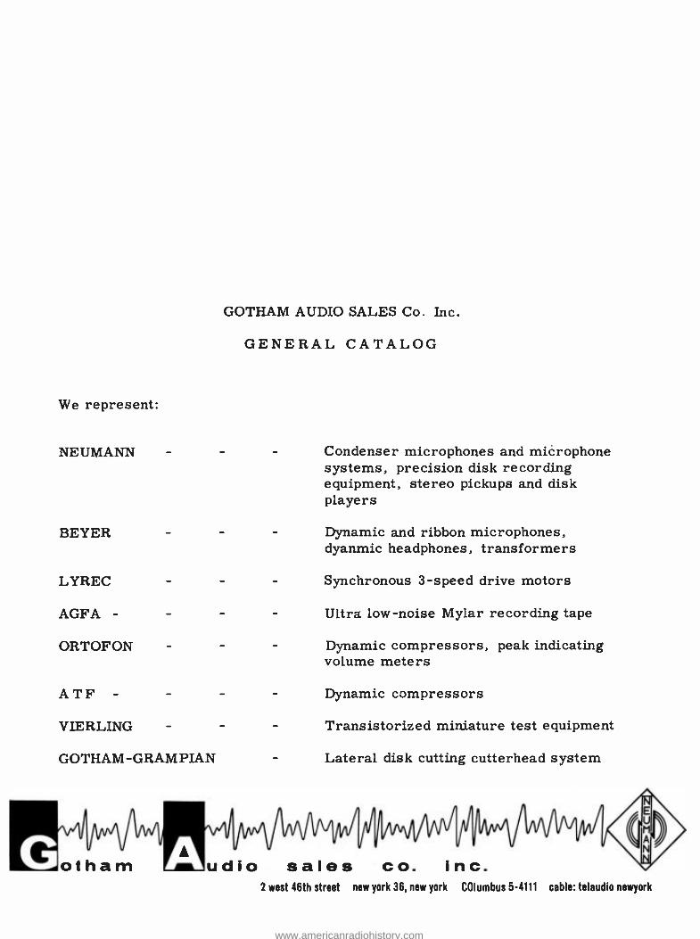
N.Y. PHILHARMONIC LEONARD BERNSTEIN, COND.
ISAAC STERN, VIOLIN AT COLUMBIA RECORDS
LONG PLAYING STEREO RECORD ALBUM - CAPITOL RECORDS INC.
LONG PLAYING RECORD ALBUM RELEASE - CAPITOL RECORDS INC.
CHANCELLOR ADENAUER ADDRESSING BUNDESTAG - BONN, GERMANY
1
g'; - SOW 'FM z, 40 iz - r? , .
*is
swinging sketches
Kdv
and hi. nUItii(
SELECTED EVERY TIME...FOR QUALITY & DEPENDABILITY
www.americanradiohistory.com
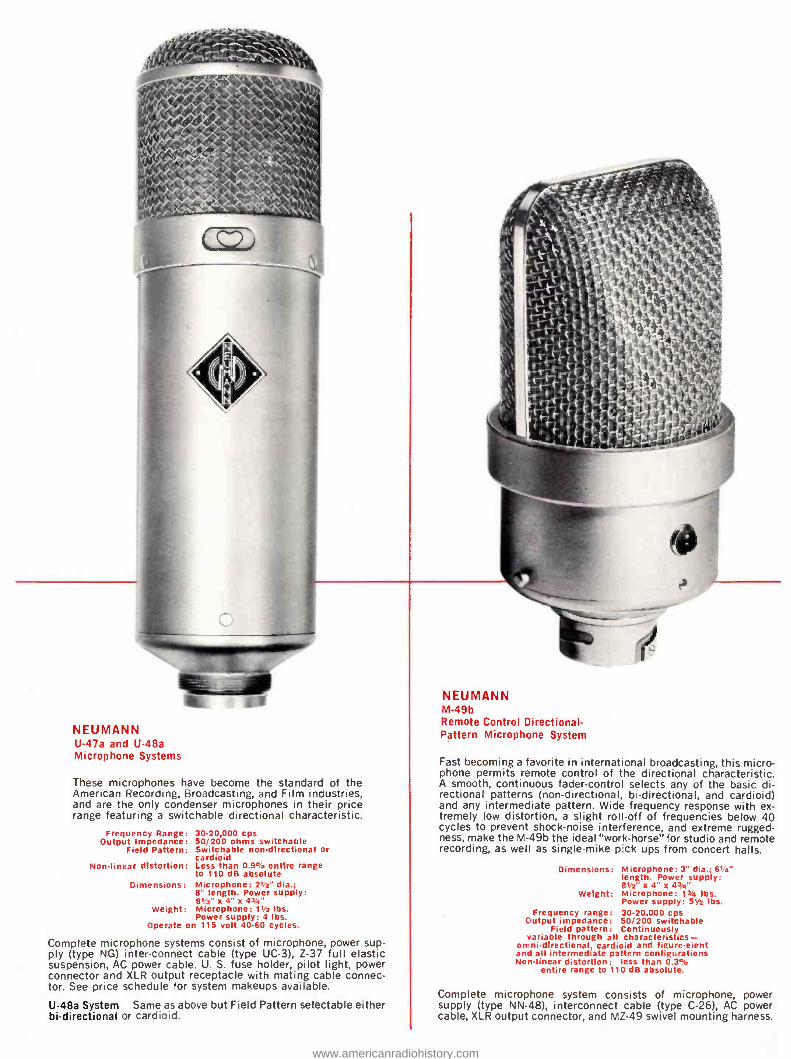
NEUMANN U -47a and U -48a Microphone Systems
These microphones have become the standard of the American Recording, Broadcasting, and Film industries, and are the only condenser microphones in their price range featuring a switchable directional characteristic.
Frequency Range: Output Impedance:
Field Pattern:
30- 20,000 cps 50/200 ohms switchable Switchable non -directional or cardioid
Non -linear distortion: Less than 0.9% entire range to 110 dB absolute
Dimensions: Microphone: 21/2' dia.; 8" length. Power supply: 81/2 "x4 "x43/4'
Weight: Microphone: 11/2 lbs. Power supply: 4 lbs.
Operate on 115 volt 40 -60 cycles.
Complete microphone systems consist of microphone, power sup- ply (type NG) inter- connect cable (type UC -3), Z -37 full elastic suspension, AC power cable. U. S. fuse holder, pilot light, power connector and XLR output receptacle with mating cable connec- tor. See price schedule for system makeups available.
U -48a System Same as above but Field Pattern selectable either bi- directional or cardioid.
NEUMANN M -49b Remote Control Directional - Pattern Microphone System
Fast becoming a favorite in international broadcasting, this micro- phone permits remote control of the directional characteristic. A smooth, continuous fader -control selects any of the basic di- rectional patterns (non -directional, bi- directional, and cardioid) and any intermediate pattern. Wide frequency response with ex- tremely low distortion, a slight roll -off of frequencies below 40 cycles to prevent shock -noise interference, and extreme rugged- ness, make the M -49b the ideal "work- horse" for studio and remote recording, as well as single -mike pick ups from concert halls.
Dimensions: Microphone: 3" dia.; 61/2" length. Power supply: 81/2' x 4" x 43/4"
Weight: Microphone: 13/4 lbs. Power supply: 51/2 lbs.
Frequency range: 30. 20,000 cps Output impedance: 50/200 switchable
Field pattern: Continuously variable through all characteristics -
omni-directional, cardioid and. figure -eicht and all intermediate pattern configurations Non -linear distortion: less than 0.3%
entire range to 110 dB absolute.
Complete microphone system consists of microphone, power supply (type NN -48), interconnect cable (type C -26), AC power cable, XLR output connector, and MZ -49 swivel mounting harness.
www.americanradiohistory.com
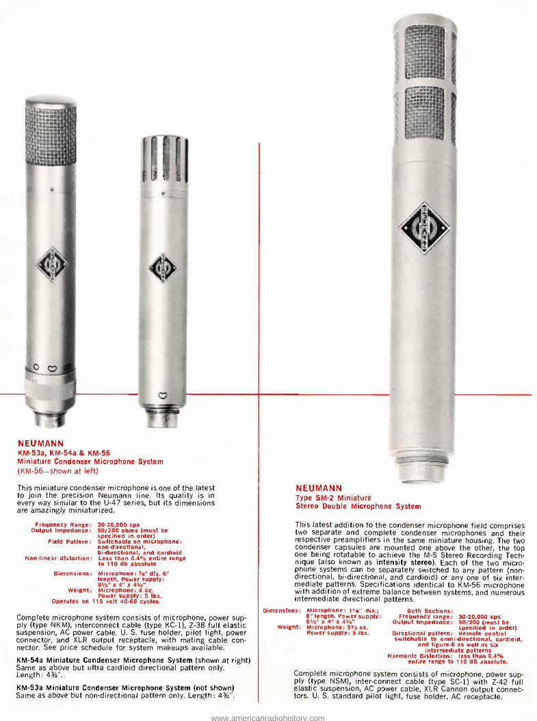
NEUMANN KM -53a, KM -54a & KM -56 Miniature Condenser Microphone System (KM -56 -shown at left)
This miniature condenser microphone is one of the latest to join the precision Neumann line. Its quality is in every way similar to the U -47 series, but its dimensions are amazingly miniaturized.
Frequency Range: Output Impedance:
Field Pattern:
Non -linear distortion:
Dimensions:
Weight:
Operates on
30- 20,000 cps 50/200 ohms (must be specified in order) Switchable on microphone: non -directional, bi- directional, and cardioid Less than 0.4% entire range to 110 db absolute Microphone: 7/e" dia. 6" length. Power supply: 81/2" x 4" x 47/4" Microphone: 4 oz. Power supply: 5 lbs.
115 volt 40 -60 cycles.
Complete microphone system consists of microphone, power sup- ply (type NKM), interconnect cable (type KC -1), Z -38 full elastic suspension, AC power cable. U. S. fuse holder, pilot light, power connector, and XLR output receptacle, with mating cable con- nector. See price schedule for system makeups available.
KM -54a Miniature Condenser Microphone System (shown at right) Same as above but ultra cardioid directional pattern only. Length: 43/4 ".
KM -53a Miniature Condenser Microphone System (not shown) Same as above but non -directional pattern only. Length: 43/4".
NEUMANN Type SM -2 Miniature Stereo Double Microphone System
This latest addition to the condenser microphone field comprises two separate and complete condenser microphones and their respective preamplifiers in the same miniature housing. The two condenser capsules are mounted one above the other, the top one being rotatable to achieve the M -S Stereo Recording Tech- nique (also known as intensity stereo). Each of the two micro- phone systems can be separately switched to any pattern (non - directional, bi- directional, and cardioid) or any one of six inter- mediate patterns. Specifications identical to KM -56 microphone with addition of extreme balance between systems, and numerous intermediate directional patterns.
Dimensions: Microphone: Pia" dia.; 8" length. Power supply: 8112" x4" x 42/4'
Weight: Microphone: 9112 oz. Power supply: 5 lbs.
Both Sections: Frequency range: 30. 20,000 cps
Output Impedance: 50/200 (must be specified in order)
Directional pattern: Remote control switchable to omni -directional, cardioid,
and figure -8 as well as six intermediate patterns
Harmonic Distortion: less than 0.4% entire range to 110 dB absolute.
Complete microphone system consists of microphone, power sup- ply (type NSM), inter -connect cable (type SC -1) with Z -42 full elastic suspension, AC power cable, XLR Cannon output connec- tors. U. S. standard pilot light, fuse holder, AC receptacle.
www.americanradiohistory.com
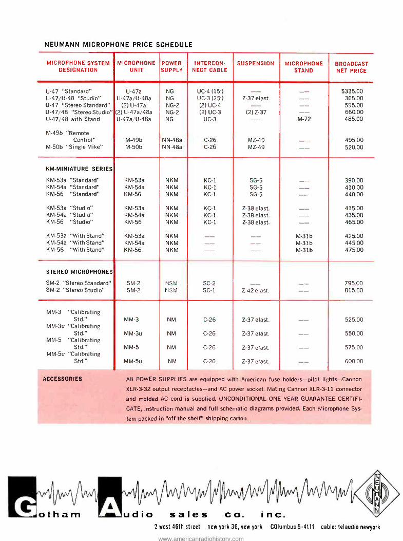
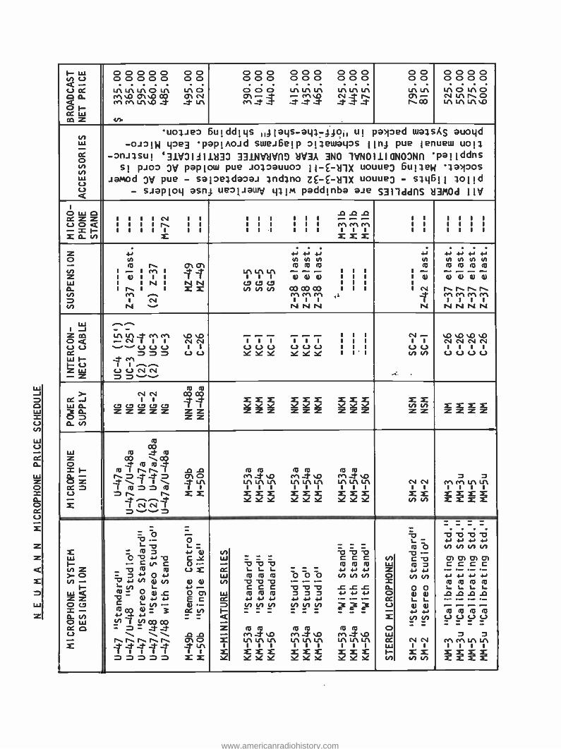
NEUMANN MICROPHONE PRICE SCHEDULE
MICROPHONE SYSTEM DESIGNATION
MICROPHONE UNIT
POWER SUPPLY
INTERCON- NECT CABLE
SUSPENSION MICROPHONE STAND
BROADCAST NET PRICE
U -47 "Standard" U -47a NG UC -4 (15') -- -- $335.00 U- 47/U -48 "Studio" U- 47a/U -48a NG UC -3 (25') Z -37 elast. -- 365.00 U -47 "Stereo Standard" (2) U -47a NG -2 (2) UC -4 -- -- 595.00 U -47/48 "Stereo Studio" (2) U- 47a/48a NG -2 (2) UC -3 (2) Z -37 -- 660.00 U -47/48 with Stand U -47a-U -48a NG UC -3 -- M -72 485.00
M -49b "Remote Control" M -49b NN -48a C -26 MZ -49 -- 495.00
M -50b "Single Mike" M -50b NN -48a C -26 MZ -49 -- 520.00
KM- MINIATURE SERIES
KM -53a "Standard" KM -53a NKM KC -1 SG -5 -- 390.00 KM -54a "Standard" KM -54a NKM KC -1 SG -5 -- 410.00 KM -56 "Standard" KM -56 NKM KC -1 SG -5 -- 440.00
KM -53a "Studio" KM -53a NKM KC -1 Z- 38elast. -- 415.00 KM -54a "Studio" KM -54a NKM KC -1 Z- 38elast. -- 435.00 KM -56 "Studio" KM -56 NKM KC -1 Z- 38elast. -- 465.00
KM -53a "With Stand" KM -53a NKM -- -- M -31b 425.00 KM -54a "With Stand" KM -54a NKM -- -- M -31b 445.00 KM -56 "With Stand" KM -56 NKM -- -- M -31b 475.00
STEREO MICROPHONES
SM -2 "Stereo Standard" SM -2 NSM SC -2 -- -- 795.00 SM -2 "Stereo Studio" SM -2 NSM SC -1 Z -42 elast. -- 815.00
MM -3 "Calibrating Std." MM -3 NM C -26 Z -37 elast. -- 525.00
MM -3u "Calibrating Std." MM -3u NM C -26 Z -37 elast. -- 550.00
MM -5 "Calibrating Std." MM -5 NM C -26 Z -37 elast. -- 575.00
MM -5u "Calibrating Std." MM -5u NM C -26 Z -37 elast. -- 600.00
ACCESSORIES All POWER SUPPLIES are equipped with American fuse holders -pilot lights- Cannon
XLR -3 -32 output receptacles -and AC power socket. Mating Cannon XLR -3 -11 connector
and molded AC cord is supplied. UNCONDITIONAL ONE YEAR GUARANTEE CERTIFI-
CATE, instruction manual and full schematic diagrams provided. Each Microphone Sys-
tem packed in "off- the -shelf" shipping carton.
otham dio sales co. inc. 2 west 46th street new york 36, new york COlumbus 5 -4111 cable: telaudio newyork
www.americanradiohistory.com
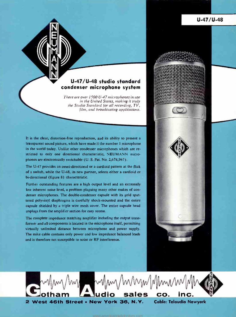
U-47/U-48
U- 47/U -48 studio standard condenser microphone system
There are over 1500 U-47 microphones in use in the United States, making it truly
the Studio Standard for all recording, TV, film, and broadcasting applications.
It is the clear, distortion -free reproduction, and its ability to present a
transparent sound picture, which have made it the number 1 microphone
in the world today. Unlike other condenser microphones which are re-
stricted to only one directional characteristic, NEUMANN micro-
phones are electronically switchable (U. S. Pat. No. 2,678,967) .
The U -47 provides an omni -directional or a cardioid pattern at the flick of a switch, while the U -48, its new partner, selects either a cardioid or
bi- directional (figure 8) characteristic.
Further outstanding features are a high output level and an extremely
low inherent noise level, a problem plaguing many other makes of con-
denser microphones. The double- condenser capsule with its gold sput-
tered polyvinyl diaphragms is carefully shock- mounted and the entire
capsule shielded by a triple wire mesh cover. The entire capsule head
unplugs from the amplifier section for easy access.
The complete impedance matching amplifier including the output trans-
former and all components is located in the microphone itself, permitting
virtually unlimited distance between microphone and power supply.
The mike cable contains only power and low impedance balanced leads
and is therefore not susceptible to noise or RF interference.
otham udio sales 2 West 46th Street New York 36, N. Y
co. inc. Cable: Telaudio Newyork
www.americanradiohistory.com
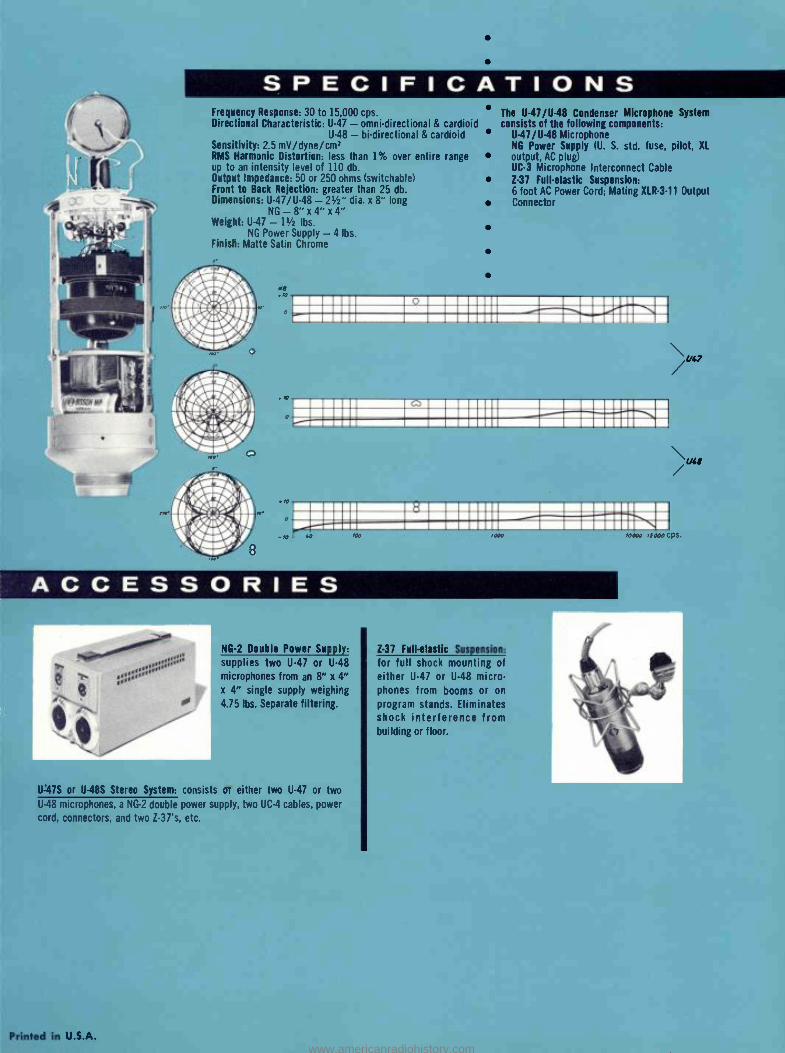
SPECIFICATIONS Frequency Response: 30 to 15,000 cps. Directional Characteristic: U -47 - omni- directional & cardioid
U -48 - bi- directional & cardioid Sensitivity: 2.5 mV /dyne /cm= RMS Harmonic Distortion: less than 1% over entire range up to an intensity level of 110 db. Output Impedance: 50 or 250 ohms (switchable) Front to Back Rejection: greater than 25 db. Dimensions: U- 41/U -48 - 21/2" dia. x 8" long
NG- 8 "x4 "x4" Weight: U -47 - 11/2 lbs.
NG Power Supply -4 lbs. Finish: Matte Satin Chrome
The U- 47/U -48 Condenser Microphone System consists of the following components:
U- 41/U -48 Microphone NG Power Supply (U. S. std. fuse, pilot, XL
output. AC plug) UC -3 Microphone Interconnect Cable Z -37 Full -elastic Suspension: 6 foot AC Power Cord; Mating X1R -3 -11 Output Connector
=MENU INOMMI
K1=MIII -II =MEMO 4^7NIIM11III =MIMI =MEMIII isiM111iiiIl>tititill
ACCESSORIES
.'ÿ NG -2 Double Power Supply:
supplies two U -47 or U -48
microphones from an 8" x 4" x 4" single supply weighing
4.75 lbs. Separate filtering.
U =41S or U -48S Stereo System: consists of either two U -47 or two
U -48 microphones, a NG -2 double power supply. two UC -4 cables, power
cord. connectors, and two I -31s, etc.
Printed in U.S.A.
Z -37 Full- elastic Suspension:
for full shock mounting of
either U -47 or U -48 micro- phones from booms or on
program stands. Eliminates shock interference from building or floor.
www.americanradiohistory.com
M-49b / M-50 b
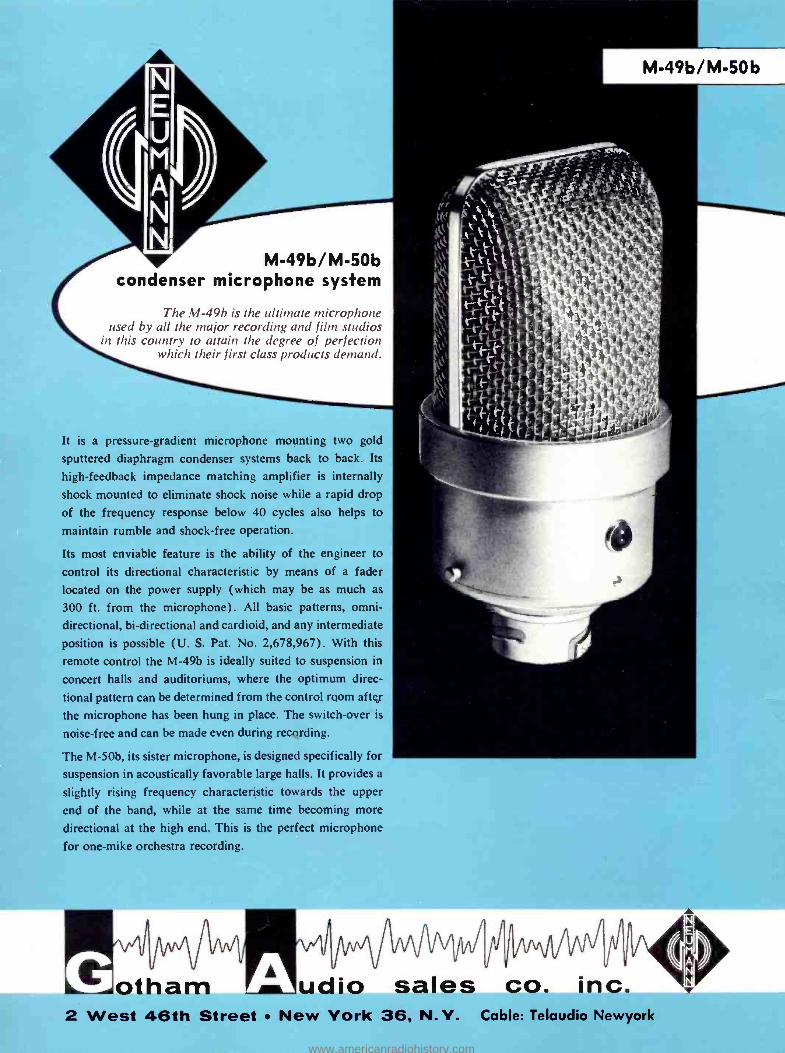
M- 49b /M -50b condenser microphone system
The M-49b is the ultimate microphone used by all the major recording and film studios
in this country to attain the degree of perfection which their first class products demand.
It is a pressure -gradient microphone mounting two gold
sputtered diaphragm condenser systems back to back. Its
high- feedback impedance matching amplifier is internally
shock mounted to eliminate shock noise while a rapid drop
of the frequency response below 40 cycles also helps to
maintain rumble and shock -free operation.
Its most enviable feature is the ability of the engineer to
control its directional characteristic by means of a fader
located on the power supply (which may be as much as
300 ft. from the microphone). All basic patterns, omni-
directional, bi- directional and cardioid, and any intermediate
position is possible (U. S. Pat. No. 2,678,967). With this
remote control the M -49b is ideally suited to suspension in
concert halls and auditoriums, where the optimum direc-
tional pattern can be determined from the control room after
the microphone has been hung in place. The switch -over is
noise -free and can be made even during recording.
The M -50b, its sister microphone, is designed specifically for
suspension in acoustically favorable large halls. It provides a
slightly rising frequency characteristic towards the upper
end of the band, while at the same time becoming more
directional at the high end. This is the perfect microphone
for one -mike orchestra recording.
w1
oinar Pl/i/vgivq,
udio sales co. inc. 2 West 46th Street New York 36, N.Y. Cable: Telaudio Newyork
www.americanradiohistory.com
O
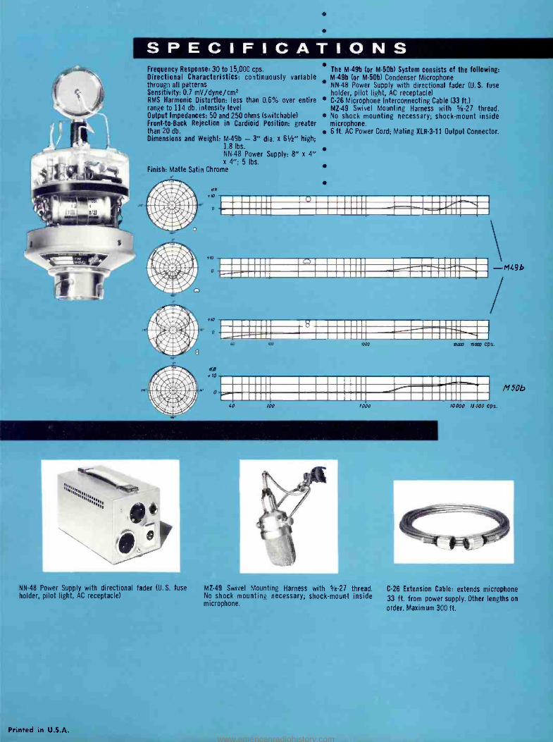
SPECIFICATIONS Frequency Response: 30 to 15,000 cps. Directional Characteristics: continuously variable through all patterns Sensitivity: 0.7 mV /dyne /cml RMS Harmonic Distortion: less than 0.6% over entire range to 114 db. intensity level Output Impedances: 50 and 250 ohms (switchable) Front -to -Back Rejection in Cardioid Position: greater than 20 db. Dimensions and Weight: M -49b - 3" dia. x 61/2" high;
1.8 lbs. NN -48 Power Supply: 8" x 4" x 4 "; 5 lbs.
Finish: Matte Satin Chrome
I
The M -49b (or M -50b) System consists of the following: M -49b for M -50b) Condenser Microphone NN -48 Power Supply with directional fader (U.S. fuse holder, pilot light, AC receptacle) C -26 Microphone Interconnecting Cable (33 ft.) MZ -49 Swivel Mounting Harness with 5/e -27 thread. No shock mounting necessary; shock -mount inside microphone. 6 ft. AC Power Cord; Mating X1.R -3 -11 Output Connector.
MEn11111711111MII 111111 rM' MM EMMNI immulm_ oori iC° os 1immomoom '
MEMO =.Go IMON ii: tis 11111111=tiN
-M49b
poop 500 cps.
10000 75000 ps.
M50b
er
NN -48 Power Supply with directional fader (U. S. fuse holder, pilot light, AC receptacle)
Printed in U.S.A.
.1"
MZ -49 Swivel Mounting Harness with s/8 -27 thread. No shock mounting necessary; shock -mount inside microphone.
C -26 Extension Cable: extends microphone
33 ft. from power supply. Other lengths on
order. Maximum 300 ft.
www.americanradiohistory.com
KM-54a/ KM-53a
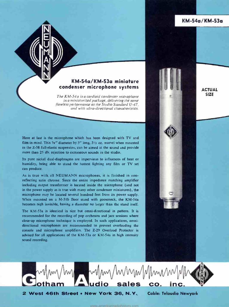
KM- 54a /KM -53a miniature condenser microphone systems
The KM -54a is a cardioid condenser microphone in a miniaturized package, delivering the same
flawless performance as the Studio Standard U-47 .
and with ultra -directional characteristics.
ACTUAL SIZE
Here at last is the microphone which has been designed with I V and film in mind. This 7 /H" diameter by 5" long, 31/2 oz. marvel when mounted in the Z -38 full- elastic suspension, can be aimed at the sound and provide more than 25 db. rejection to extraneous sounds in the studio.
Its pure nickel dual- diaphragms are impervious to influences of heat or humidity, being able to stand the hottest lighting any film or TV set
can produce.
As is true with all NEUMANN microphones, it is finished in non- reflecting satin chrome. Since the entire impedance matching amplifier including output transformer is located inside the microphone (and not in the power supply as is true with many other condenser miniatures), the microphone may be located several hundred feet from its power supply. When mounted on a M-3 lb floor stand with gooseneck, the KM -54a becomes nigh invisible, having a diameter no larger than the stand itself.
The KM -53a is identical in size but omni -directional in pattern. It is
recommended for the recording of pop orchestra and jazz sessions where close -up microphone technique is employed. In such applications, omni- directional microphones are recommended to prevent overloading the console and microphone amplifiers. The Z -29 Overload Protector is
advised for all applications of the KM -53a or KM -54a in high intensity sound recording.
udio sales co. inc. 2 West 46th Street New York 36, N.Y. Cable: Telaudio Newyork
www.americanradiohistory.com
PdQ0 1d000
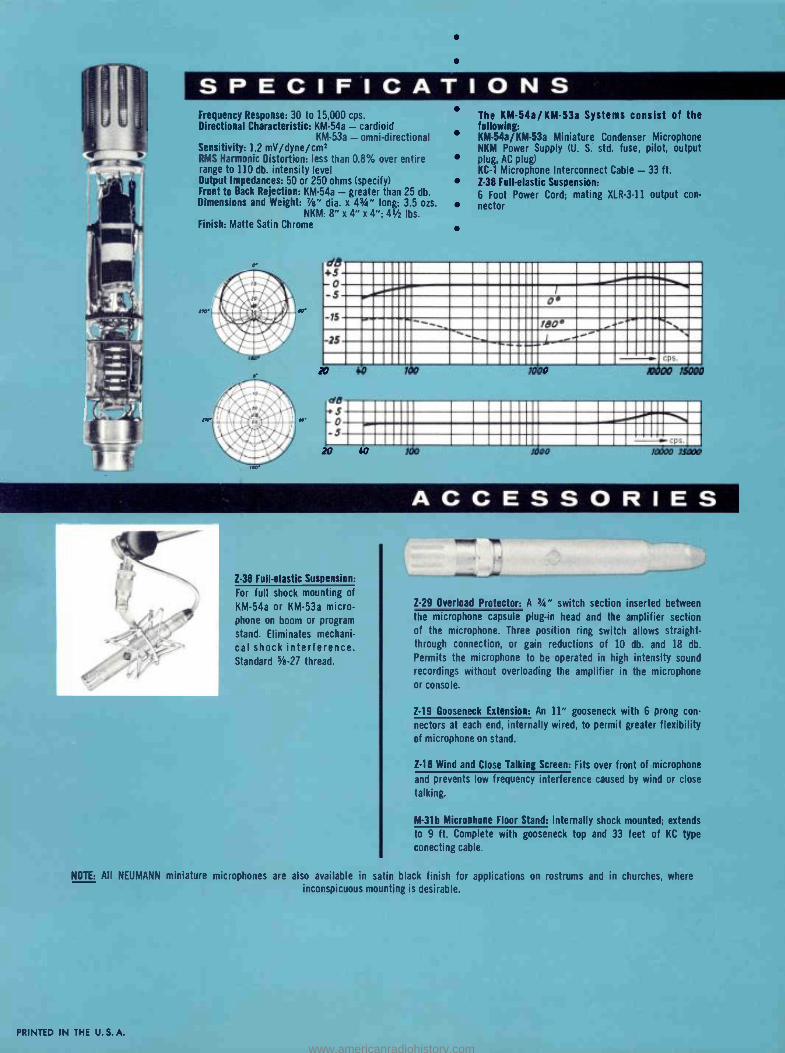
SPECIFICATIONS Frequency Response: 30 to 15,000 cps. Directional Characteristic: KM -54a - cardioid
KM -53a - omni- directional Sensitivity: 1.2 mV /dyne /cm1 RMS Harmonic Distortion: less than 0.8% over entire range to 110 db. intensity level Output Impedances: 50 or 250 ohms (specify) Front to Back Rejection: KM -54a - greater than 25 db. Dimensions and Weight: 78" dia. x 43/4" long; 3.5 ozs.
NKM: 8"x4 "x4";41 /z lbs. Finish: Matte Satin Chrome
The KM- 54a /KM -53a Systems consist of the following: KM- 54a /KM -53a Miniature Condenser Microphone NKM Power Supply (U. S. std. fuse, pilot, output plug, AC plug) KC -1 Microphone Interconnect Cable - 33 ft. Z -38 Full- elastic Suspension:
6 Foot Power Cord: mating XLR -3 -11 output con- nector
15 !BO °
2$ a cps.
40
.°w
o 5 4
rc
40 100 pko 1000 MOO
ACCESSORIES
Z -38 Full- elastic Suspension:
For full shock mounting of
KM -54a or KM -53a micro- phone on boom or program
stand. Eliminates mechani-
cal shock interference. Standard 1/4-27 thread.
NOTE: All NEUMANN miniature microphones are
PRINTED IN THE U.S.A.
lowly 'OR
Z -29 Overload Protector: A 3/4" switch section inserted between
the microphone capsule plug -in head and the amplifier section of the microphone. Three position ring switch allows straight -
through connection, or gain reductions of 10 db. and 18 db.
Permits the microphone to be operated in high intensity sound
recordings without overloading the amplifier in the microphone or console.
Z -19 Gooseneck Extension: An 11" gooseneck with 6 prong con-
nectors at each end, internally wired, to permit greater flexibility of microphone on stand.
Z -18 Wind and Close Talking Screen: Fits over front of microphone
and prevents low frequency interference caused by wind or close
talking.
M -31b Microphone Floor Stand: Internally shock mounted; extends
to 9 ft. Complete with gooseneck top and 33 feet of KC type
conecting cable.
also available in satin black finish for applications on rostrums and in churches, where inconspicuous mounting is desirable.
www.americanradiohistory.com
KM-56
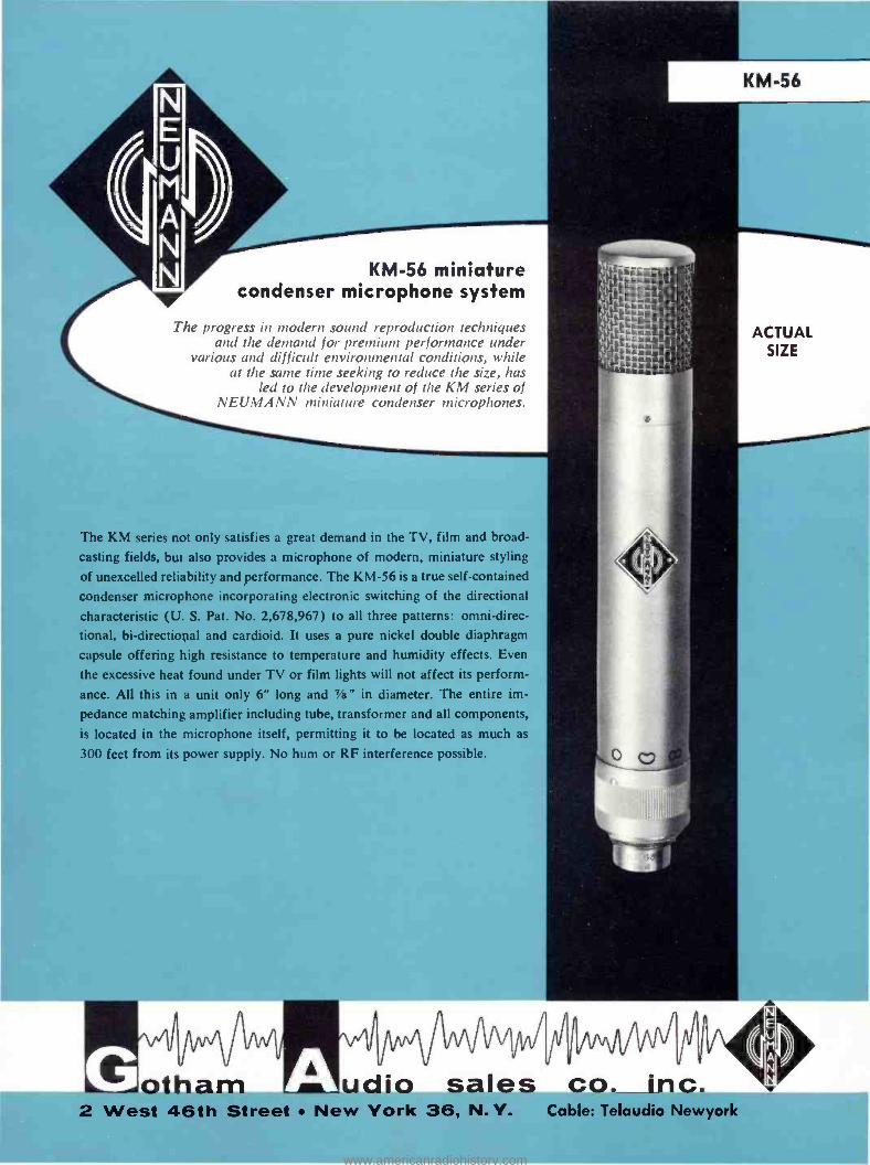
KM -56 miniature condenser microphone system
The progress in modern sound reproduction techniques and the demand for premium performance under
various and difficult environmental conditions, while at the same time seeking to reduce the size, has
led to the development of the KM series of NEUMANN miniature condenser microphones.
ACTUAL SIZE
The KM series not only satisfies a great demand in the TV, film and broad-
casting fields, but also provides a microphone of modern, miniature styling
of unexcelled reliability and performance. The KM -56 is a true self -contained
condenser microphone incorporating electronic switching of the directional
characteristic (U. S. Pat. No. 2,678,967) to all three patterns: omni- direc-
tional, bi- directional and cardioid. It uses a pure nickel double diaphragm
capsule offering high resistance to temperature and humidity effects. Even
the excessive heat found under TV or film lights will not affect its perform-
ance. All this in a unit only 6" long and 7 /s" in diameter. The entire im-
pedance matching amplifier including tube, transformer and all components, is located in the microphone itself, permitting it to be located as much as
300 feet from its power supply. No hum or RF interference possible.
otham Plqi/vgivol/f
udio sales co. inc. 2 West 46th Street New York 36, N.Y. Cable: Telaudio Newyork
www.americanradiohistory.com
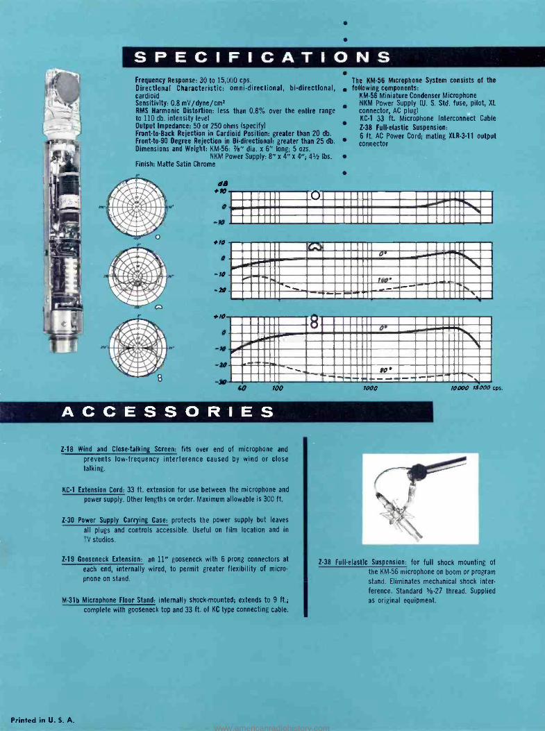
SPECIFICATIONS Frequency Response: 30 to 15.000 cps. Directional Characteristic: omni -directional, bi- directional, cardioid Sensitivity: 0.8 mV /dyne /cm' RMS Harmonic Distortion: less than 0.8% over the entire range to 110 db. intensity level Output Impedance: 50 or 250 ohms (specify) Front -to -Back Rejection in Cardioid Position: greater than 20 db. Front -to -90 Degree Rejection in Bi- directional: greater than 25 db. Dimensions and Weight: KM -56: "s" dia. x 6" long; 5 ozs.
NKM Power Supply: 8" x 4" x 4 "; 41/2 lbs. Finish: Matte Satin Chrome
11
The KM -56 Microphone System consists of the following components:
KM -56 Miniature Condenser Microphone NKM Power Supply (U. S. Std. fuse, pilot, XL
connector, AC plug) KC -1 33 ft. Microphone Interconnect Cable
2.38 Full- elastic Suspension: 6 ft. AC Power Cord; mating XLR -3 -11 output connector
NONNI -mum NUMB w111
014 ,,iIl1.,,M.i.::. .... . I11\\ í111111 .ii:l1111IIEf!=111111111111P*1111= 11 IliIIi7 111Morriiiiaifiin 11111IM71
8 0'
00'
ACCESSORIES Z -18 Wind and Close -talking Screen: fits over end of microphone and
prevents low- frequency interference caused by wind or close talking.
KC -1 Extension Cord: 33 ft. extension for use between the microphone and
power supply. Other lengths on order. Maximum allowable is 300 ft.
Z -30 Power Supply Carrying Case: protects the power supply but leaves
all plugs and controls accessible. Useful on film location and in
TV studios.
Z -19 Gooseneck Extension: an 11" gooseneck with 6 prong connectors at
each end, internally wired, to permit greater flexibility of micro-
phone on stand.
M -31b Microphone Floor Stand: internally shock -mounted: extends to 9 ft.;
complete with gooseneck top and 33 ft. of KC type connecting cable.
Printed in U. S. A.
Z-38 Full -elastic Suspension: for full shock mounting of
the KM -56 microphone on boom or program
stand. Eliminates mechanical shock inter- ference. Standard Vo-27 thread. Supplied
as original equipment.
www.americanradiohistory.com
E U M A N N
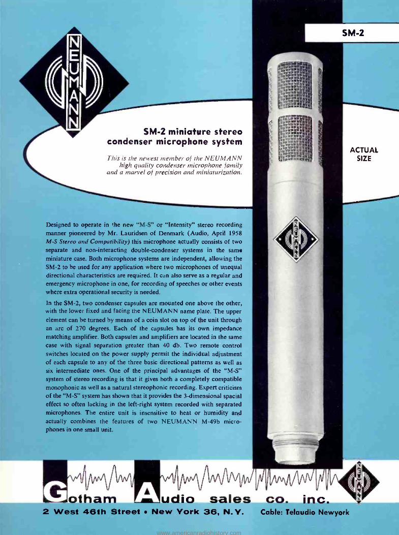
SM -2 miniature stereo condenser microphone system
This is the newest member of the NEUMANN high quality condenser microphone family
and a marvel of precision and miniaturization.
Designed to operate in the new "M -S" or "Intensity" stereo recording manner pioneered by Mr. Lauridsen of Denmark (Audio, April 1958 M -S Stereo and Compatibility) this microphone actually consists of two separate and non -interacting double- condenser systems in the same miniature case. Both microphone systems are independent, allowing the SM -2 to be used for any application where two microphones of unequal directional characteristics are required. It can also serve as a regular and emergency microphone in one, for recording of speeches or other events where extra operational security is needed.
In the SM -2, two condenser capsules are mounted one above the other, with the lower fixed and facing the NEUMANN name plate. The upper element can be turned by means of a coin slot on top of the unit through an arc of 270 degrees. Each of the capsules has its own impedance matching amplifier. Both capsules and amplifiers are located in the same case with signal separation greater than 40 db. Two remote control switches located on the power supply permit the individual adjustment of each capsule to any of the three basic directional patterns as well as six intermediate ones. One of the principal advantages of the "M -S" system of stereo recording is that it gives both a completely compatible monophonic as well as a natural stereophonic recording. Expert criticism of the "M -S" system has shown that it provides the 3- dimensional spacial effect so often lacking in the left -right system recorded with separated microphones. The entire unit is insensitive to heat or humidity and actually combines the features of two NEUMANN M -49b micro- phones in one small unit.
V"J
otham
SM-2
ACTUAL SIZE
udio sales co. inc. 2 West 46th Street New York 36, N.Y. Cable: Telaudio Newyork
www.americanradiohistory.com
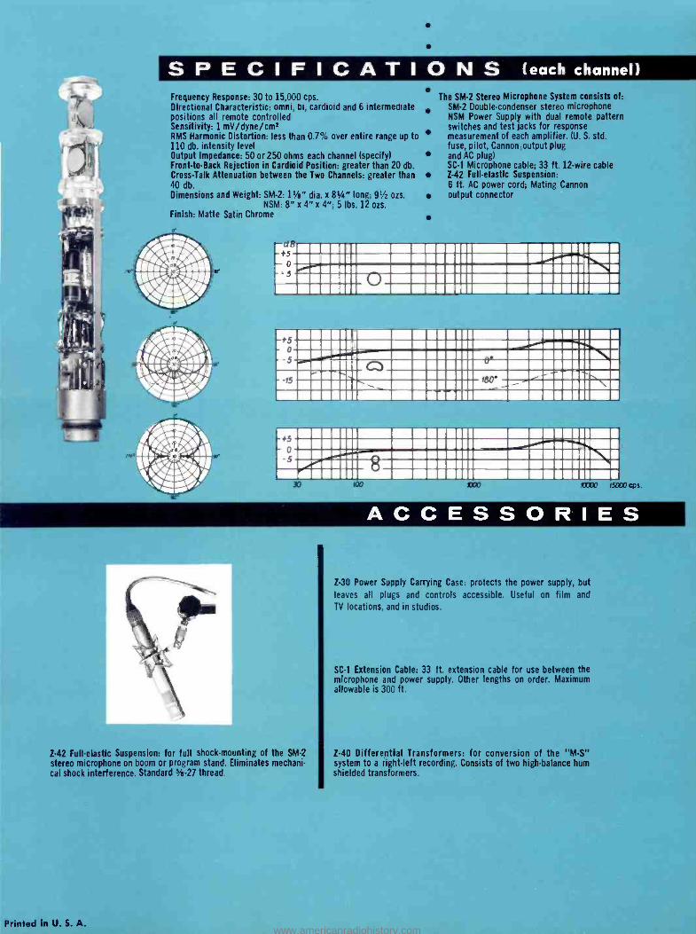
SPECIFICATIONS (each channel) Frequency Response: 30 to 15,000 cps. Directional Characteristic: omni, bi, cardioid and 6 intermediate positions all remote controlled Sensitivity: 1 mV /dyne /cm' RMS Harmonic Distortion: less than 0.7% over entire range up to 110 db. intensity level Output Impedance: 50 or 250 ohms each channel (specify) Front -to -Back Rejection in Cardioid Position: greater than 20 db. Cross -Talk Attenuation between the Two Channels: greater than 40 db. Dimensions and Weight: SM -2: 11/2" dia. x 81/2" long; 91/2 ozs.
NSM: 8" x 4" x 4 "; 5 lbs. 12 ozs. Finish: Matte Satin Chrome
The SM -2 Stereo Microphone System consists of: SM -2 Double- condenser stereo microphone NSM Power Supply with dual remote pattern switches and test jacks for response measurement of each amplifier. (U. S. std. fuse, pilot, Cannon output plug and AC plug) SC -1 Microphone cable: 33 ft. 12 -wire cable Z -42 Full- elastic Suspension: 6 ft. AC power cord; Mating Cannon output connector
+5 o 5 o
11 = 111
111II ENlllMIIIMMIRiIIMMII:1 .1111!12::ii111l111\ 111111 Q =MIlliMIIIIMM111.111 iilel lll rso M111ii\ii= MIII:111 11:01111MINI111 Q1/1111
110111n111 111 M111 111 =M111 iiì:! MIL!:::IAMIE11111=111HI\\ Mi111 w111 111m =a111is111 mo1mon lOODO 15(00 cps.
ACCESSORIE S
Z -42 Full- elastic Suspension: for full shock -mounting of the SM -2
stereo microphone on boom or program stand. Eliminates mechani- cal shock interference. Standard 5/e -27 thread.
Printed in U. S. A.
Z -30 Power Supply Carrying Case: protects the power supply, but
leaves all plugs and controls accessible. Useful on film and
TV locations, and in studios.
SC -1 Extension Cable: 33 ft. extension cable for use between the microphone and power supply. Other lengths on order. Maximum allowable is 300 ft.
Z -40 Differential Transformers: for conversion of the "M -S" system to a right -left recording. Consists of two high -balance hum shielded transformers.
www.americanradiohistory.com
"M -S" Stereophony and Compatibility
GERHART BORE and STEPHEN F. TEMMER
Anyone who has ever heard either track of a stereo tape by itself realizes that it is not a
good substitute for a well- recorded monaural tape. The author describes a system which will eliminate this trouble, not only on stereo tapes, but also on stereodiscs and in broad- casting -with particular emphasis on its value in combinations of FM and FM- multiplex.
OUR EARS ENABLE US not only to ap- preciate sounds according to their intensities and duration, but to
pin -point their origin in terms of direc- tion and distance. To determine the di- rection of sound we utilize several facul- ties: the ability to calculate the differ- ence in time of arrival of the two initial transient components of a sound at the two ears; the sensitivity to intensity and sound -color differences at the two ears; and, in the case of one ear alone, the perception of the curvature of the wave - front, which for point sources decreases with distance. As a means of measuring. the ear makes use of the phase differ- ence between pressure and velocity, par- ticularly in the low- frequency compo- nents and in low- frequency transients, which amounts to 90 deg. at the point of origin, and 0 deg. for plane -wave propagation. In the diffused sound field of enclosed spaces, it is also possible to estimate the distance of the sound source by means of the intensity difference be- tween the direct sound and its subse- quent reflections from the boundary sur- faces.
Practical Stereophonic Sound Transmission
Normal Classical Two -channel Trans- mission. In the "classical" method, pick -up is carried out by two micro- phones accurately matched as to fre- quency response and polar characteris- tic. In practice, adequate matching is only attainable in the case of high -grade condenser microphones, free from sub- sidiary resonances within the transmis- sion band. Cardioid microphones, which have proved particularly satisfactory in stereophonic sound -filin systems, are preferred. Thanks to their single -sided directional pattern, the direct sound, so
George Neumann Laboratories, Berlin, Germany.
"President, Gotham Audio Develop- ment Corporation, 2 W. 46th St., New York 16, N. Y.
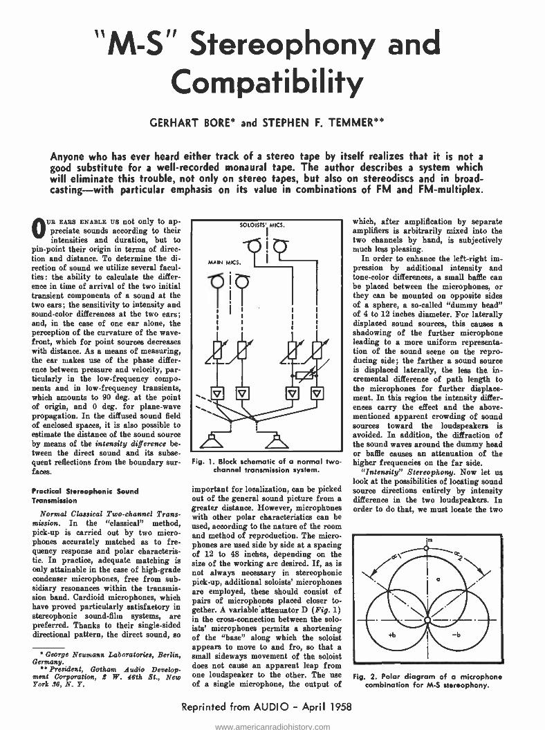
Fig. 1. Block schematic of a normal two - channel transmission system.
important for localization, can be picked out of the general sound picture from a greater distance. However, microphones with other polar characteristics can be used, according to the nature of the room and method of reproduction. The micro- phones are used side by side at a spacing of 12 to 48 inches, depending on the size of the working arc desired. If, as is not always necessary in stereophonic pick -up, additional soloists' microphones are employed, these should consist of pairs of microphones placed closer to- gether. A variable ' attenuator D (Fig. 1) in the cross- connection between the solo- ists' microphones permits a shortening of the "base" along which the soloist appears to move to and fro, so that a small sideways movement of the soloist does not cause an apparent leap from one loudspeaker to the other. The use of a single microphone, the output of
Reprinted from AUDIO April 1958
which, after amplification by separate amplifiers is arbitrarily mixed into the two channels by hand, is subjectively much less pleasing.
In order to enhance the left -right im- pression by additional intensity and tone -color differences, a small baffle can be placed between the microphones, or they can be mounted on opposite sides of a sphere, a so- called "dummy head" of 4 to 12 inches diameter. For laterally displaced sound sources, this causes a shadowing of the further microphone leading to a more uniform representa- tion of the sound scene on the repro- ducing side; the farther a sound source is displaced laterally, the less the in- cremental difference of path length to the microphones for further displace- ment. In this region the intensity differ- ences carry the effect and the above - mentioned apparent crowding of sound sources toward the loudspeakers is avoided. In addition, the diffraction of the sound waves around the dummy head or baffle causes an attenuation of the higher frequencies on the far side.
"Intensity" Stereophony. Now let us look at the possibilities of locating sound source directions entirely by intensity difference in the two loudspeakers. In order to do that, we must locate the two
Fig. 2. Polar diagram of a microphone combination for M -S stereophony.
www.americanradiohistory.com
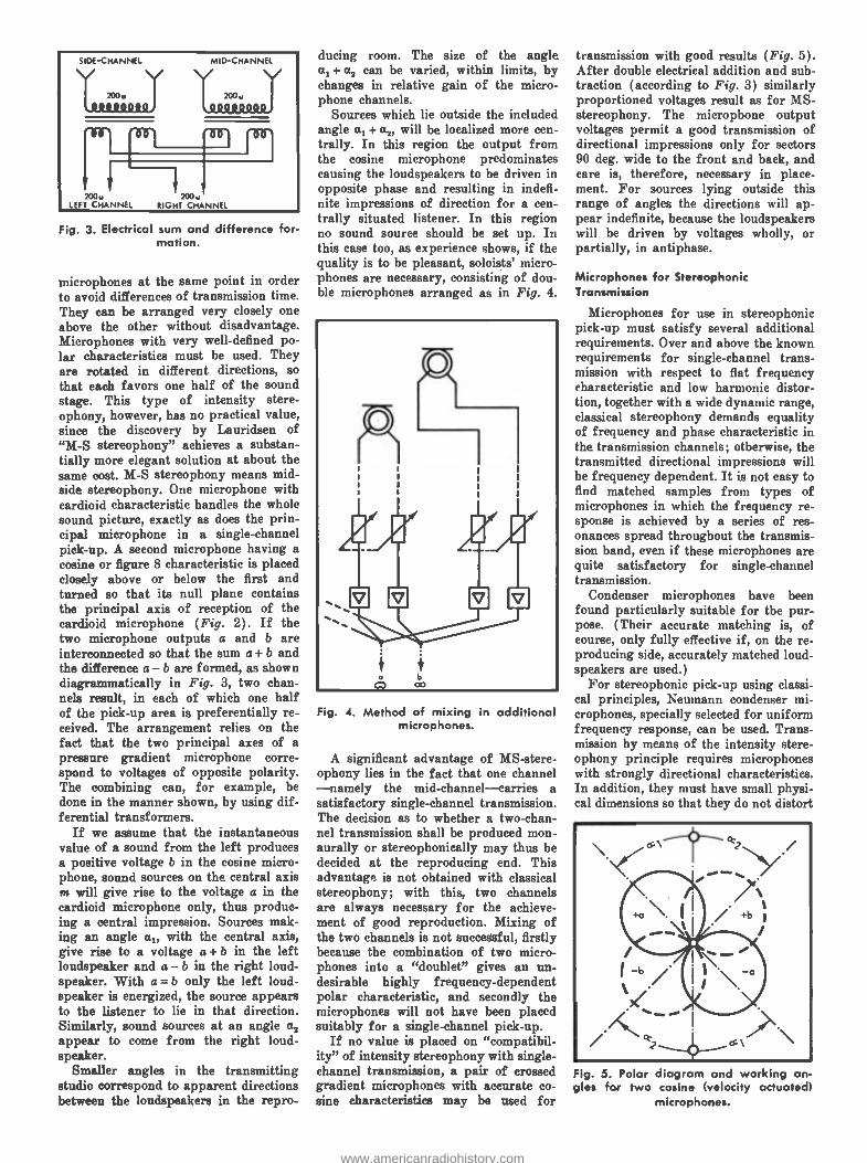
Fig. 3. Electrical sum and difference for- mation.
microphones at the saine point in order to avoid differences of transmission time. They can be arranged very closely one above the other without disadvantage. Microphones with very well -defined po- lar characteristics must be used. They are rotated in different directions, so that each favors one half of the sound stage. This type of intensity stere- ophony, however, has no practical value, since the discovery by Lauridsen of "M -S stereophony" achieves a substan- tially more elegant solution at about the same cost. M -S stereophony means mid - side stereophony. One microphone with cardioid characteristic handles the whole sound picture, exactly as does the prin- cipal microphone in a single -channel pick -up. A second microphone having a cosine or figure 8 characteristic is placed closely above or below the first and turned so that its null plane contains the principal axis of reception of the cardioid microphone (Fig. 2). If the two microphone outputs a and b are interconnected so that the sum a + b and the difference a b are formed, as shown diagrammatically in Fig. 3, two chan- nels result, in each of which one half of the pick -up area is preferentially re- ceived. The arrangement relies on the fact that the two principal axes of a pressure gradient microphone corre- spond to voltages of opposite polarity. The combining can, for example, be done in the manner shown, by using dif- ferential transformers.
If we assume that the instantaneous value of a sound from the left produces a positive voltage b in the cosine micro- phone, sound sources on the central axis m will give rise to the voltage a in the cardioid microphone only, thus produc- ing a central impression. Sources mak- ing an angle a with the central axis, give rise to a voltage a + b in the left loudspeaker and a b in the right loud- speaker. With a = b only the left loud- speaker is energized, the source appears to the listener to lie in that direction. Similarly, sound sources at an angle a, appear to come from the right loud- speaker.
Smaller angles in the transmitting studio correspond to apparent directions between the loudspeakers in the repro-
ducing room. The size of the angle a, + a2 can be varied, within limits, by changes in relative gain of the micro- phone channels.
Sources which lie outside the included angle a, + a will be localized more cen- trally. In this region the output from the cosine microphone predominates causing the loudspeakers to be driven in opposite phase and resulting in indefi- nite impressions of direction for a cen- trally situated listener. In this region no sound source should be set up. In this case too, as experience shows, if the quality is to be pleasant, soloists' micro- phones are necessary, consisting of dou- ble microphones arranged as in Fig. 4.
Fig. 4. Method of mixing in additional microphones.
A significant advantage of MS- stere- ophony lies in the fact that one channel -namely the mid -channel- carries a satisfactory single -channel transmission. The decision as to whether a two -chan- nel transmission shall be produced mon- aurally or stereophonically may thus be decided at the reproducing end. This advantage is not obtained with classical stereophony; with this, two channels are always necessary for the achieve- ment of good reproduction. Mixing of the two channels is not successful, firstly because the combination of two micro- phones into a "doublet" gives an un- desirable highly frequency- dependent polar characteristic, and secondly the microphones will not have been placed suitably for a single -channel pick -up.
If no value is placed on "compatibil- ity" of intensity stereophony with single - channel transmission, a pair of crossed gradient microphones with accurate co- sine characteristics may be used for
transmission with good results (Fig. 5). After double electrical addition and sub- traction (according to Fig. 3) similarly proportioned voltages result as for MS- stereophony. The microphone output voltages permit a good transmission of directional impressions only for sectors 90 deg. wide to the front and back, and care is, therefore, necessary in place- ment. For sources lying outside this range of angles the directions will ap- pear indefinite, because the loudspeakers will be driven by voltages wholly, or partially, in antiphase.
Microphones for Stereophonic Transmission
Microphones for use in stereophonic pick -up must satisfy several additional requirements. Over and above the known requirements for single -channel trans- mission with respect to flat frequency characteristic and low harmonic distor- tion, together with a wide dynamic range, classical stereophony demands equality of frequency and phase characteristic in the transmission channels; otherwise, the transmitted directional impressions will he frequency dependent. It is not easy to find matched samples from types of microphones in which the frequency re- sponse is achieved by a series of res- onances spread throughout the transmis- sion band, even if these microphones are quite satisfactory for single- channel transmission.
Condenser microphones have been found particularly suitable for the pur- pose. (Their accurate matching is, of course, only fully effective if, on the re- producing side, accurately matched loud- speakers are used.)
For stereophonic pick -up using classi- cal principles, Neumann condenser mi- crophones, specially selected for uniform frequency response, can be used. Trans- mission by means of the intensity stere- ophony principle requires microphones with strongly directional characteristics. In addition, they must have small physi- cal dimensions so that they do not distort
Fig. 5. Polar gles for two
diagram and working an- cosine (velocity actuated)
microphones.
www.americanradiohistory.com
the sound field when mounted in close proximity.
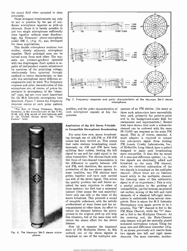
These stringent requirements can only be met in practice by the use of con- denser microphone capsules as pick -up elements. Since it is barely possible to put two single microphones sufficiently close together without some disadvan- tage, the Neumann' stereo -microphone model SM 2, (Fig. 6), was developed for these applications.
This double microphone contains two similar, closely adjacent, microphone capsules. Their principal axes can be turned away from each other. The cap- sules are pressure- gradient operated with two diaphragms. Each system is ca- pable of independent remote adjustment by variation of the polarizing voltage, continuously from spherical through cardioid to cosine characteristic, so that with this microphone many different ar- rangements may be tried. The frequency response and polar characteristics of this microphone are, of course, of prime im- portance in stereophony of the "classi- cal" type, but are even more important for the M -S Intensity stereophony here described. Figure 7 shows the frequency response curves at each polar pattern
' The firm of Georg Neumann, Berlin, Germany, is the manufacturer of the U -47, M -49, and BM series of microphones Bold in the United States under the "Tele- funken" label.
Fig. 6. The Neuman SM -2 stereo micro- phone.
as.
_5r...:: 10.
..... 70. ...00 .
db
i0oo
- 1,000
o;òoo ïs,000 15,000
db '
SV 01
30
1.... 100 a.
-10 e----.. Q - 1AOo
0 - ----- - 30 100 W00 10,000 15,000
.... 8 : . '
. . . . . ....
100 moo 1
I
Mn:: 0;0oo i 5,000
loo - 1,000 10,000
Fig. 7. Frequency response and polar characteristics of the Neuman SM -2 stereo microphone.
position, and the polar characteristics of each microphone capsule at key fre- quencies
Application of the M -S Stereo Principle to Compatible Stereophonic Broadcasting
For some time now, stereo broadcast- ing through use of AM -FM or FM -FM means has been carried on. This means that radio stations broadcasting simul- taneously on AM and FM have been splitting their outlets, feeding the left signal to one and the right signal to the other transmitter. The obvious fault with this form of two -channel transmission is the difference in quality between AM and FM, and, therefore, the uneven re- production of the two stereo signals. In some localities, two FM státions have gotten together and have each carried one side of the stereo signal. This solves the quality problem but still leaves un- solved the main objection to either of these systems: the fact that a monaural listener (that means the vast majority) hears only one side or the other of the stereo broadcast. This presents a sound of complete unbalance, with the melody predominant at some times and the ac- companiment at other times. An effort to reduce the distance between the micro- phones in the original pick -up will help this situation, but at the same time will reduce the stereo effect for the stereo listener.
Now let us examine the imminent start of FM Multiplex Stereo. In this method, one of the stereo signals is broadcast on one of the multiplex sub-
carriers of an FM station. (As many as three such subcarriers have successfully been used, primarily for point -to -point and in the background -music field for restaurants and supermarkets.) Recent tests have shown that such a subcarrier channel can be endowed with the same 50- 15,000 cps response as the main FM signal. This is, of course, essential. A small adapter is required to extract this sub- carrier signal from existing FM tuners. Crosby Laboratories, Inc., of Hicksville, Long Island, have a patent designed to make such broadcasting more compatible. It does this by means of a sum -and -difference system ; i.e., the two signals are electrically added and broadcast on the main FM channel, while the electrical subtraction of the two signals is broadcast on the multiplex channel. (Since there are no listeners tuned solely to the multiplex channel, the listening value of this subtractive signal is of no importance.) This is only a partial solution to the problem of compatibility ; partial because, as pointed out earlier, mixing of the left and right channels of a classical left -right stereo system is undesirable from several view- points. Here is where the M -S Intensity Stereophony once again proves to be a solution. The "M" channel is fed to the FM Main Channel, while the "S" chan- nel is fed to the Multiplex Channel. At the receiving end, the Main -Channel only listener will get the centrally placed monaural microphone output. Using the same sum- and -difference converter (Fig. 3) as shown previously will resolve these two signals into left and right stereo channels. The same converter, inciden-
www.americanradiohistory.com
tally, is needed for the Crosby sum -and- difference system.
The M -S Stereo Principle Applied to Stereo Tapes
It. is interesting to note that after the "M" and "S" channels have been converted into Left and Right channels, the insertion of another identical con- verter (Fig. 3) will reproduce the origi- nal "M" and "S" signals. This is in sharp contrast to recordings made in the Left -Right or classical system. A stereo -tape, whose left and right tracks were derived from a recording made with the Neumann SM -2 Intensity- Stereo Microphone, may be played back with a full -track playback head, which, in essence, acts as a converter and adds the two signals and restores the "M" channel; the true mid -channel of the cardioid element.
The M -S Stereo Principle Applied to Stereo Discs
Again here the Intensity Stereophony shows definite advantages. Indeed, these advantages are such that the M -S prin- ciple can be applied without the neces- sity of the previously described con- verter. We can actually use the geometry of the groove as a converter. The stereo-
disc principle which has recently been adopted is based on playback with a cartridge sensitive to signals placed in the groove at an angle of 45 deg. to the vertical. There is no compulsion placed on the record manufacturer for using a 45-45 cutterhead to achieve this groove. The 45 -deg. modulation can be assumed to be a vector resulting from lateral and vertical signal. Let us use a cutter capable of recording a vertical and lateral signal on a disc, and modulate the lateral channel with "M" output of the SM -2 Microphone, and the vertical channel with the, `.'S" output. A 45-45 stereo cartridge will effectively act as our converter (Fig. 3) in playback, pro- viding the sum of M and S on one side of the groove and the difference on the other. At the same time, this groove played back with a monaural lateral playback cartridge will reproduce the "M" or true mid -channel alone. (It must be pointed out that the damage to the vertical groove component by cartridges with low vertical compliance will be exactly the same as in stereo discs cut from left -right stereo tapes using a 45 -45 degree cutting head.)
Conclusions
Much research has been done in the field of stereophonies from the stand-
point of reproduction through ear- phones, loudspeakers, two-channel, three - channel, or multichannel systems. Judg- ment in the use of different recording techniques has been on the basis of many and varied criteria. These have included attempts to startle the listener; tries at spreading the orchestra out to many times its actual concert width; arbitrary assignment of instrumental sections and vocalists to left and right channels, without regard to representa- tion of realism; and many more. We believe that with the advent of stereo - disc and stereo multiplex FM, a tre- mendous interest in sound reproduction will be generated; an interest many times that of recent years. And after we have settled down to real enjoyment of our newly -discovered dimension, rather than the open- mouthed, startled look one sees nowadays on the faces of people when first confronted with stereo, then I believe we will go back and re- examine some of the basic truths of stereo recording with perhaps a view toward a return to realism and a true third dimension. The writers firmly be- lieve that the Intensity -Stereophony principle represents reproduction of a true third dimension. 16
www.americanradiohistory.com
Rotham 1
Broadcast
Audio
Price List
PRICES EFFECTIVE SEPTEMBER 1, 1959
I ivi/i/NAN'AfA4 dio sales co. inc.
2 west 46th street new york 36, new york COlumbus 5 -4111 cable: telautlio newyork
www.americanradiohistory.com
Z Z
E
W
Z
F- W (I) U Q - (..) CC D d < O F- cC w m =
00000 0 0 00000 O O . . .
II\ L11 Lf\ Q L1\ Lf\ 0 ML.O O\ 1.O 00 al N M M Lf\ O L(\
v).
000 O O O 000 0 0 0 000 O O O . . - 0 0 O LC) Lf\ Lf\ U\ LI\ L(\
01 - - M O N N. N1
0 0 00 L/\ L(1 CT - N. CO
0000 0000 . . .
Lf\ O Lf\ 0 N Lf\I 0 LI\ L(\ Lf\ \Q
V) W
e oN
N
U a
ul paed wa;s(S auoyd uolaeo 6uiddiys L ays-ayl-33o lo
-oaolW yoe3 papinoad swea6eip oilewayos uni pue lenuew uol1
-onalsu! `31tf313112130 331Ntf2itffl9 21ti311 3N0 lt/NOI1IaNO3Nfl Pa! Iddns sl paoo 0y paplow pue aoloauuoo lI--2llX uouue0 6ulleW laloos
aaMod 0y pue - saloeldaoaa lndlno z--a-lX uouue0 - sly6ll lolld - sJaploy asn3 ueolaawy y1jM paddlnba aJe S311ddflS 213MOd lIt/
1
o w D L r Z Z U O Q -2 F- E0_ V)
1 1 I 1 N 1 1
I 1 I 1 N . I I
1 1 1 1 1 1 I i _a _ca _a
1 I I 1 I I .- 1 I I 1 1 I M M M I I I 1 I I I 1 I EE>=
1 1
I I
1 I
1 1 I 1
1 1 1 1 MI I I
Z O - V) Z W d V) 0 N
1J U1
(0 N. O1 Q1 I - I 0'1 I
I N I 1 1 I 1 I NJ 1 N NJ 1 N. 1 I EX
M 1 N
N .-
aJ aJ aJ U1 In Vf (0 (0 (0
Lf\ Lfl LA - - -- 1 I 1
I t I N N N I 1 1
(.7 L7 C7 1 I 1
V) V) V) CO CO CO I 1 I
M M M I 1 I
N NJ NJ
aJ VI (0
I -- I N 1
I N 1
N
aJ aJ aJ a-' N U1 N U1
f0 f0 CO f0 -.- -- .- Q) 0) Q) N
N. N. N. 1 M M M M
1 1 1 1 1
NJ NJ IN NJ
LU 1 -) Z m
O Q U U CL W F- F- L) Z LU -Z
- - L1\ UN M M 1/40 \O .- N I 1 1 N N v U U U 1 I
D D D (...) U M
I 1
L) U N N n
I I I
I I 1 1 I 1 1 1 1
U U U U U U 1 1 1
Y Y Y ]C ]C X I I I
N- 1 1
U U N N
1/40 \O O %D N N N N 1 1 1 1
L.] 0 0 0
>-
LU 0- 3 O D Ii V)
co co NN CO 00
C7C7C7C7C7 1 I
z z z z z z z z z EEZ XXX XXX NC]C]C ]CYC CYY z z z z z z z z
f E NLN z z i>r2 i z z z z
W Z CD = F- d- O Z K O U - Z
(0 CO
IO . (0 CO CO -I- (o (o --I-
(0 I N. N. I .n _0 N. O4- . D Ql co _1-\ 1 1 \ LI 1
1 (0 O O (0 I t ON. N. >=i
----- --. 1 N N 1 p -' 0
(0 (0 (0 (0 CO (0 Ms..0 M CO MVD Lf\ L(\ If) L() L.I\ 1.11 Lf\ Lf\ Lf\
1 I 1 I 1 1 1 1 1 EEE >=ES EzE Y Y Y g ]C g Y
N N 1 I
E E N v)
7 7 M M L(\ LC)
1 1 1 1 f EEE f E f E
LU F- V) Z >- O V) - F- W Q Z Z O C7 2 - Ó W Lr D U Z
.. Jl
O O v -
7 (0 aJ 0I
C73 .1-, -0 C - C N C O - _ (0 (0 U E 7 a.( O aJ
-0 a-+ N (L) N LU D) L N L a-J .- D - O N L O O
(I) )-+ iJ E c C L 1n -- 6) -
CO 0) - 3 N 4" - - N N CO - O - -/- \ \\ _in .I) N. n N. N. N. Q\ 0
L1\ 1 1 1 1 1 1 1 >>>D E2
N W - W V)
W K O '- Q Z Z
I Z ]L
_
-0 17 '0 ___ C C C (0 (0 (0 L L L - - - +-+ aJ
(D (0 (D O O O (N LN V) -o -0 -0 .- .- .- C C C -D L t .0 (0 (0 ID 7 7 7 r-' a-' a' aJ aJ a-+ aJ aJ aJ - .- .- V) N N IN V) tN 3 _ _ _ _ _ _
(D (0 (0 (D (D (0 r.-1 _../- ..O M - LO M \O Lf\ LI\ LI\ LI\ Lf1 LI\ LI\ Lf\ L11
I I I I I I I I 1 XXX XXX XXX ]Cg]C ]C]LY ]C]C]L
V) W Z O 2 C1. 0 CC L) - E O LU [Y W F- v)
L - (1) O
C-p ÿ tN N O O N N
N N a aJ N (f) _ _
N N 1 1 XX V)VI
v v v +- N +J aJ V) N V V)
O) O) O) O)
-- C C C C
a-' a-' +' +-' (0 (1 (0 CO
L L L L -0 .0 .n .D
^ - --- --- (0 co (0 (0 0 0 0 U _ _ _ _
7 7 M M Lfl Lf\
I 1 1 1
X 2 i E EEEE
www.americanradiohistory.com
f W
z
-0 s- (0 U) L
a) _ o u) a) C (0 ++ O v N O .0 a L L O ut a) L L I L+' 0 4- C a) U O+' L UI EE> a(0 C7 O u - v++ O - Ol L ut +' I 7
w a- O- o z 3- 3 c L c++ 7 (o O o L U O C L a L C + E Q) a) a) + - - E L ++ - L 7 a) 4- > u (0 - L uf - + ; T U) N +
V1 U +' -+' T Ul L C Uf 1-+ (0 3 c L c(0 -- a) (0 c -17 E (A - a) +-+ (0 a) L 7 O E L 3 - _c
E c L O c _ v+-+ v O a 0 V O w o u a- .0 (o a L E o o a
+' a) a) L E +' a) a) 7 (0 u) T L O +-+ L ut L C - L L a 7(0 - L ut ++ L U - ++ UC O 1 E 7 3 + ++ O c- a) L+ c O a) - a) O. L +' L O O ^ a) L- O a (0 + +, a) O U (0 T o 7 T C L U V1 L N L a) U a) Uf U C (0 -L a) - (0 4- +' O N _ (0 1 +
c - 7 - ut C O - - E > u O T O a) 4- O a) ++ I O O a) - Ql 3 O E ]c L a- U - E- U c O ++ ++ L
CO C a) L 7 -+ a L C U U co - UI L+' - 7 - -0 - C N E u - L a)
9-13) (0 N T(0 L 1 O u, N (0
tT L a) ++ - a) - O ^ E a- +( +, + O a) a) L C a) U - a) X c < 4- c+' u, z(o -v 7 O (o a) L- O -- Z O a C ++ E O U O LU 4- -V L U 7 (0 7 L a) a) N L a m U c a) v a) L c rn a) co ut a E a) U 7 s-. O L L O ut 4- Q) (0 a) L Q) O 4- .- +' C V1 w a) + O a) - (0 (0 O a +' +' U1 L C T U L O+' C
W a) a) C 4- +' +, U a N C 0 - - - ++ U(0 z a) - - C C u 4- C - - - +' - a) - a) T L- I- L (a o r-. '- a) (n o a) O (0 O v 3 (o (o >= U c(o v
a) = (0 (0 ++ - N +' - - U (0 +'
"Cn
C L a) (0 7 W u 0 U c + ^ O L a) ++ - - a) (o a) O-. v u) zO Ql L (0 = U) O - 1 +' L a) U) 7 (0 +' U ,L +' N a L - a) Z L +' - - I- E+' u N o a- 7 0 L c a) u u) (o L- c u(o a) uf a- a) u -v O a) a) a) a O p O M w O L a) 3 +' a) N (0 b 4- a) 3 a) a U) UI a) U 1 +' L O L +' o ut C> 1 c a) L ut O - L T C= a W 7 a) +' T T C- C L!1 O +' - (0 (0 +> > C C Z O Ql Ql WI L ut O ++ - 00 N L L Ol L 0 O O T C C U ++ U U M a C O I- C+' L O 4- +' C (0 - ZI y a) L y w 1 O ._ ++ __ ++ +, O= C rn Q u) - a) LC ¢ C V) a1 ++ Ol N L L + - C (0 C L- ++ U (0 DI Q) a) ++ O C + u a) T + 3' (0 G. -(0 a) W _ C L C L ._ w Ql - a) 7 .- - w O + U1 L (0 U N L dI - I-a +(r\ c E t v a E c v ut ++ 7 c w u- a L f a) (o rn a) a) a L. o a) rn a) - +-( (o u) v -I
a) +' L 1 - L > U) 7 a) - _ 7 (0 4- (0 +) L +' C T Uf L UI O L O N a) - Ql U) a+-+ - - U C - V) a) _ ._ (0 y in 4-) w O rO a(o+- C u a (011\ u C 1] L E++ C ro E > 4 O L L Co a) - a) w(0 a +' a) (o Ql E U 1 (0 (0 j a) 4- - 1 L O 4 - , (1) -0 > . - . j ) 1 _ 7 a) u a) O a+' c co a) +' ++ O a) L! U N X L- (0 Ql a) a) U) C a) ut V1 ut - L ++ - U - Z u) u) - L c z a) rn a) (n C U+-+ o c (o O +' U O a) C u. OI T C E (D - O L - L C a) L C 1] +-( co C Q C - L (0 - ut 7 - L a O .- L U a) v a) I-- I - L 4-, N a) O (o O O U a) a) L - - a) U Q
_ + +' - ut z 1/I 4- a) C co ut + C L L L- + - O - a a1 CD= .1 ++ U 3 a) Ew - c O 7 ra U a) ++- a) -L 4 E cL7
c W ut v a) G. O a) O - 4 a) O u - + (O ;^ (0 u Ol O - -I a) UI (I) -0 +' V) C U1 L J-+ O Ql L i C C (0 U a) C +' N E c .. (o u) O (o Q (o + U) - w c v a) c ut ++ 7 WI a VI o a) a T V) U O U) + - a) 00 a) a) N u - co L U) 7 _co o -(A L- ut W L v c - 3 c 0 3+' - c (o u O a I 7 O a -0 (0 _ U +-) U) U (o O O O \ L +-+ X - O U 4- +.+ - +' L = E L Q (p 7 a WI
w - 0
a) u L+' c F- - L ut v uf a++ a n a +( E a) O (n U- - X V) E a) E L- C T - O 1 y U) 7 Ql IA c E 7 {nl E I- - - On u) - a) a) O d al + - L O- c - (n c 7 O a) O a) r 7 a) E+' a) J C a) L+' 4- E L - U - O - o - U U) L a) NI E +' v E w w no 3 a) ul 4- - a) L- - a) L - L a) L. U+-+ C I- L .- (0 a) O Ç L (1) +' T (0 -r)+' a) (O F L 3+' U.a - Q(0 (0 a) +' T C L Q) U
N J +i - N U) ut a) -++ .- I- u -- 3 L- w .a
E rn - LO TC N- E E4-- N v c; m +' L á(7o c L - 4- -T +' LL - ya)
1 Ó a) co co L 1.-. C C U u +-+ - E U'- a)
N co
O 7 C a) - ' (0 O N U) U) T O N (0 O Ql N (0 - L T
L 4- T O O L ut U O 7 T a) a) O (o ^ u) u a) C u L T v- O
co O +' U (0 a) - 3 a) +-+ v) L+' U S a) L- O co N Ql C L 7 - (O L C L V) +' (0 U) - t a) L 7 L U L 7 0 0 0 T a) L- 1 0 7 ( 0 - 0 4 - , = y L (I) +' O L I- + a) L a) '-+ O - VI U a) C U) +' L a) Ul L (0 C C E +' (i) a) U) L - C 4- Cl. a) (0 "0 (O I a) (0 U C-0 a) +' a O a) a) a) N 1+' a) L +' - y 4- E .0 a)-+'O L Q) a)- C C L- a)L-0 LL4-+'L i C L O -L-- F- L 4- u) ._, F- 4- E - co co 1- 3 ut a - I- +' O - +' - 1- 4- Q 3 3 -o N
0 o
H
To N
0
cc
O
i
CC
O
Z
CC
N
C
O L 4-,
-J
www.americanradiohistory.com
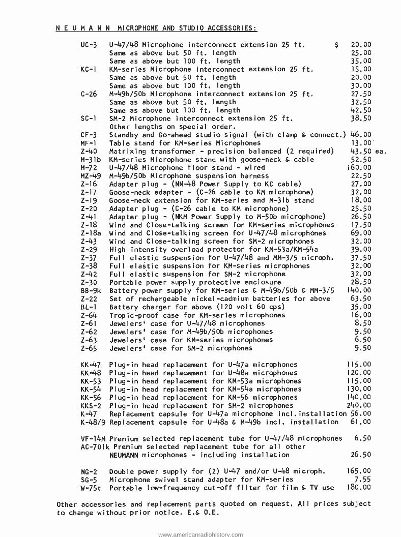
N E U M A N N MICROPHONE AND STUDIO ACCESSORIES:
UC -3 U -47/48 Microphone interconnect extension 25 ft. $ 20.00 Same as above but 50 ft. length 25.00 Same as above but 100 ft. length 35.00
KC -1 KM- series Microphone interconnect extension 25 ft. 15.00
Same as above but 50 ft. length 20.00
Same as above but 100 ft. length 30.00
C -26 M- 49b/50b Microphone interconnect extension 25 ft. 27.50 Same as above but 50 ft. length 32.50 Same as above but 100 ft. length 42.50
SC -1 SM -2 Microphone interconnect extension 25 ft. 38.50 Other lengths on special order.
CF -3 Standby and Go -ahead studio signal (with clamp & connect.) 46.00 MF -I Table stand for KM- series Microphones 13.00
Z -40 Matrixing transformer - precision balanced (2 required) 43.50 ea. M -31b KM- series Microphone stand with goose -neck S. cable 52.50 M -72 U -47/48 Microphone floor stand - wired 160.00
MZ -49 M- 49b/50b Microphone suspension harness 22.50 Z -16 Adapter plug - (NN -48 Power Supply to KC cable) 27.00 Z -17 Goose -neck adapter - (C -26 cable to KM microphone) 32.00 Z -19 Goose -neck extension for KM- series and M -31b stand 18.00
Z -20 Adapter plug - (C -26 cable to KM microphone) 25.50 Z -41 Adapter plug - (NKM Power Supply to M -50b microphone) 26.50 Z -18 Wind and Close -talking screen for KM- series microphones 17.50
Z -18a Wind and Close -talking screen for U -47/48 microphones 69.00 Z -43 Wind and Close -talking screen for SM -2 microphones 32.00 Z -29 High intensity overload protector for KM- 53a /KM -54a 39.00
Z -37 Full elastic suspension for U -47/48 and MM -3/5 microph. 37.50 Z -38 Full elastic suspension for KM- series microphones 32.00 Z -42 Full elastic suspension for SM -2 microphone 32.00 Z -30 Portable power supply protective enclosure 28.50
BB -9k Battery power supply for KM- series & M- 49b/50b & MM -3/5 140.00
Z -22 Set of rechargeable nickel -cadmium batteries for above 63.50
BL -1 Battery charger for above (120 volt 60 cps) 35.00 Z -64 Tropic -proof case for KM- series microphones 16.00
Z -61 Jewelers' case for U -47/48 microphones 8.50
Z -62 Jewelers' case for M-49b/50b microphones 9.50 Z -63 Jewelers' case for KM- series microphones 6.50
Z -65 Jewelers' case for SM -2 microphones 9.50
KK -47 Plug -in head replacement for U-47a microphones 115.00
KK-48 Plug -in head replacement for U-48a microphones 120.00
KK -53 Plug -in head replacement for KM -53a microphones 115.00
KK -54 Plug -in head replacement for KM -54a microphones 130.00
KK -56 Plug -in head replacement for KM -56 microphones 140.00
KKS -2 Plug -in head replacement for SM -2 microphones 240.00
K -47 Replacement capsule for U -47a microphone incl.installation 56.00
K -48/9 Replacement capsule for U -48a & M-49b incl. installation 61.00
VF-14M Premium selected replacement tube for U -47/48 microphones 6.50
AC -701k Premium selected replacement tube for all other
NEUMANN microphones - including installation 26.50
NG -2 Double power supply for (2) U -47 and /or U -48 microph. 165.00
SG -5 Microphone swivel stand adapter for KM- series 7.55
W -75t Portable low- frequency cut -off filter for film & TV use 180.00
Other accessories and replacement parts quoted on request. All prices subject
to change without prior notice. E.& O.E.
www.americanradiohistory.com
technical
noies
Frequency Response:
Channel separation:
Source Impedance: Recommended matching
impedance:
Sensitivity: Compliance: Tracking force:
Stylus radius:
Stylus material: Weight: Dimensions:
APPLICATION:
!!'voilitham udio sales co. inc.
A//
2 WEST 46th STREET, NEW YORK 36, NEW YORK
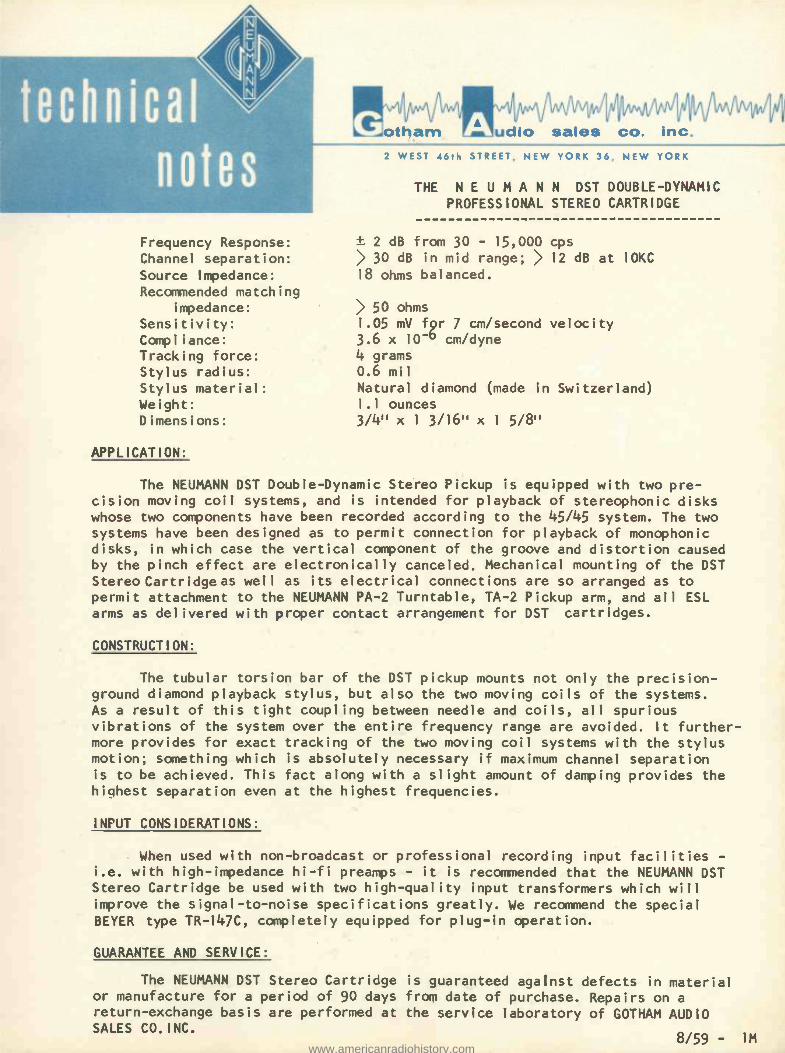
THE N E U M A N N DST DOUBLE -DYNAMIC PROFESSIONAL STEREO CARTRIDGE
± 2 dB from 30 - 15,000 cps 30 dB in mid range; > 12 dB at IOKC
18 ohms balanced.
50 ohms
1.05 mV f9r 7 cm /second velocity 3.6 x 10 -6 cm /dyne 4 grams 0.6 mil
Natural diamond (made in Switzerland) 1.1 ounces
3/4" x 1 3/16" x 1 5/8"
The NEUMANN DST Double -Dynamic Stereo Pickup is equipped with two pre- cision moving coil systems, and is intended for playback of stereophonic disks whose two components have been recorded according to the 45/45 system. The two
systems have been designed as to permit connection for playback of monophonic disks, in which case the vertical component of the groove and distortion caused by the pinch effect are electronically canceled. Mechanical mounting of the DST
Stereo Cartridge as well as its electrical connections are so arranged as to
permit attachment to the NEUMANN PA -2 Turntable, TA -2 Pickup arm, and all ESL arms as delivered with proper contact arrangement for DST cartridges.
CONSTRUCTION:
The tubular torsion bar of the DST pickup mounts not only the precision - ground diamond playback stylus, but also the two moving coils of the systems. As a result of this tight coupling between needle and coils, all spurious vibrations of the system over the entire frequency range are avoided. It further- more provides for exact tracking of the two moving coil systems with the stylus motion; something which is absolutely necessary if maximum channel separation is to be achieved. This fact along with a slight amount of damping provides the highest separation even at the highest frequencies.
INPUT CONSIDERATIONS:
When used with non -broadcast or professional recording input facilities -
i.e. with high- impedance hi -fi preamps - it is recommended that the NEUMANN DST Stereo Cartridge be used with two high -quality input transformers which will improve the signal -to -noise specifications greatly. We recommend the special BEYER type TR -147C, completely equipped for plug -in operation.
GUARANTEE AND SERVICE:
The NEUMANN DST Stereo Cartridge is guaranteed against defects in material or manufacture for a period of 90 days from date of purchase. Repairs on a
return -exchange basis are performed at the service laboratory of GOTHAM AUDIO SALES CO.INC.
8/59 - 1M www.americanradiohistory.com
S P EC Weight: 16 oz.
1
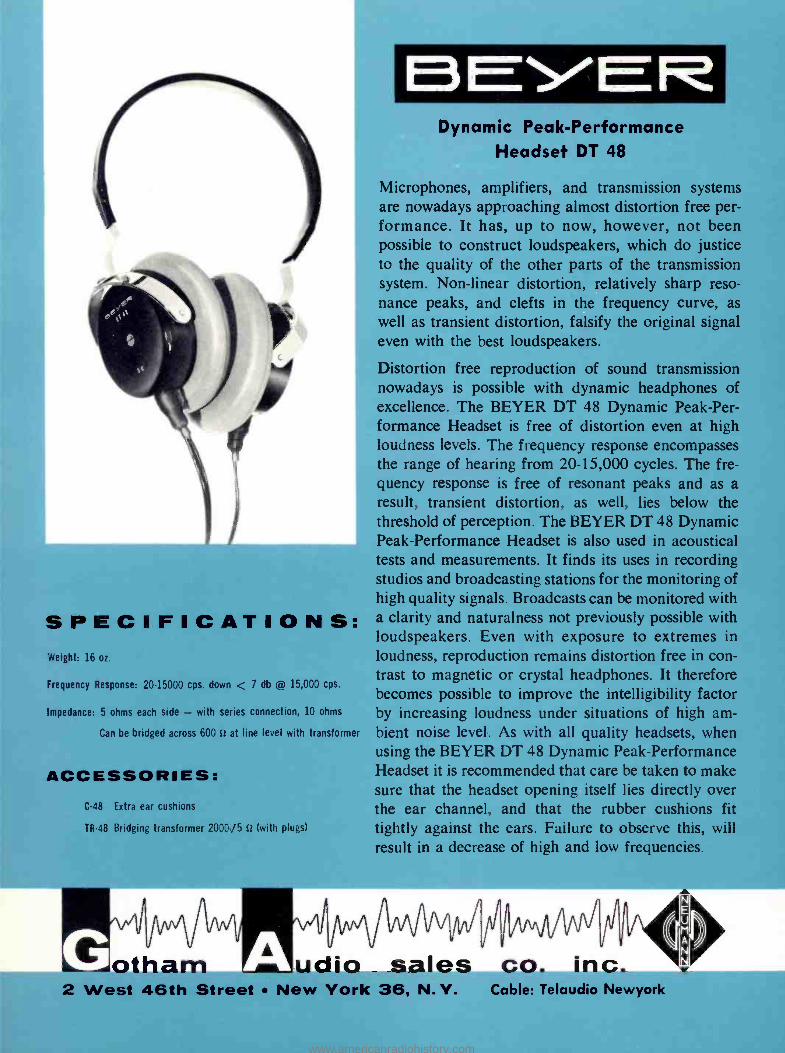
BEYER Dynamic Peak -Performance
Headset DT 48
Microphones, amplifiers, and transmission systems are nowadays approaching almost distortion free per- formance. It has, up to now, however, not been irossible to construct loudspeakers, which do justice o the quality of the other parts of the transmission
system. Non -linear distortion, relatively sharp reso- nance peaks, and clefts in the frequency curve, as well as transient distortion, falsify the original signal even with the best loudspeakers.
Distortion free reproduction of sound transmission nowadays is possible with dynamic headphones of excellence. The BEYER DT 48 Dynamic Peak -Per- formance Headset is free of distortion even at high loudness levels. The frequency response encompasses the range of hearing from 20- 15,000 cycles. The fre- quency response is free of resonant peaks and as a result, transient distortion, as well, lies below the threshold of perception. The BEYER DT 48 Dynamic Peak -Performance Headset is also used in acoustical tests and measurements. It finds its uses in recording studios and broadcasting stations for the monitoring of high quality signals. Broadcasts can be monitored with
F I C A T I O N S: a clarity and naturalness not previously possible with loudspeakers. Even with exposure to extremes in loudness, reproduction remains distortion free in con -
frequency Response: 20-15000 cps. down < 7 db @ 15,000 cps. trast to magnetic or crystal headphones. It therefore becomes possible to improve the intelligibility factor
Impedance: 5 ohms each side - with series connection, 10 ohms by increasing loudness under situations of high am- Can be bridged across 600 n at line level with transformer bient noise level. As with all quality headsets, when
using the BEYER DT 48 Dynamic Peak -Performance Headset it is recommended that care be taken to make sure that the headset opening itself lies directly over the ear channel, and that the rubber cushions fit
TR48 Bridging transformer 2000/5 tt (with plugs) tightly against the ears. Failure to observe this, will result in a decrease of high and low frequencies.
ACCESSORIES: C -48 Extra ear cushions
1
otham Ì
udio sales co. inc. 2 West 46th Street New York 36, N.Y. Cable: Telaudio Newyork
www.americanradiohistory.com
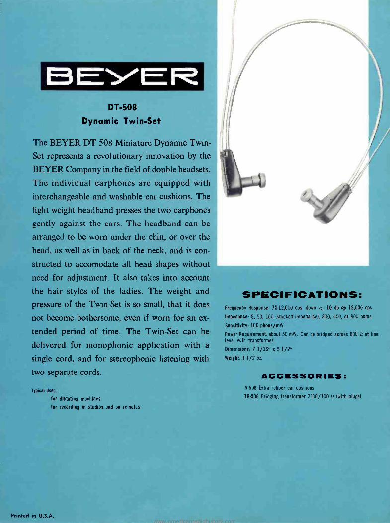
DT -508
Dynamic Twin -Set
The BEYER DT 508 Miniature Dynamic Twin
Set represents a revolutionary innovation by th
BEYER Company in the field of double headsets,
The individual earphones are equipped wit
interchangeable and washable ear cushions. The
light weight headband presses the two earphones
gently against the ears. The headband can be
arranged to be worn under the chin, or over the
head, as well as in back of the neck, and is con-
structed to accomodate all head shapes without
need for adjustment. It also takes into account
the hair styles of the ladies. The weight and
pressure of the Twin -Set is so small, that it does
not become bothersome, even if worn for an ex-
tended period of time. The Twin -Set can be
delivered for monophonic application with a
single cord, and for stereophonic listening with
two separate cords.
Typical Uses:
for dictating machines
for recording in studios and on remotes
Printed in U.S.A.
SPECIFICATIONS: Frequency Response: 70- 12,000 cps. down < 10 db @ 12,000 cps.
Impedance: 5, 50, 100 (stocked impedance), 200, 400, or 800 ohms
Sensitivity: 100 phons /mW.
Power Requirement: about 50 mW. Can be bridged across 600 tt at line level with transformer
Dimensions: 7 1/16" x 5 1/2"
Weight: 1 1/2 oz.
ACCESSORIES: N -508 Extra rubber ear cushions
TR -508 Bridging transformer 2000 /100 n (with plugs)
www.americanradiohistory.com
HF reports combining:
Audiolab Test Reports
Tested in the Home
prepared by Hirsch -Houck Laboratories
and the technical staff of High Fidelity
HF REPORT POLICY Equipment reports appearing in this section are of two types: Audiolab Test Reports and Tested in the Home Reports. AUDIOLAB TEST REPORTS are prepared for us by Hirsch -Houck Laboratories, a completely independent organization whose staff was responsible for the original Audio League Reports. Audiolab Reports are published exactly as they are received. Neither we nor manufacturers of the equipment tested are permitted to delete information from or add to the reports, to amend them in any way, or to withhold them from publication; manufacturers may add a short comment, how- ever, if they wish to do so. Audiolab Reports are made on all- electronic equipment (tuners, preampli- fiers, amplifiers, etc.). TESTED IN THE HOME REPORTS are prepared by members of our own staff on equipment that demands more subjective appraisals ( speakers, pickups, etc.). The policy concern- ing report publication and amendment by the manufacturer is the same as that for Audiolab Reports.
TIN Beyer DT -48 Headphones
SPECIFICATIONS (furnished by manufacturer): a dynamic headset for high -quality monitor- ing or private listening. Frequency range: 20 to 15,000 cps; no more than 7 db down at 15,000 cps; low- frequency response depends upon coupling of phones to ears. Impedance: .5 ohms per phone. C flans: two stand- ard phone plugs, one per phone. Price: S69. DISTRIBUTOR: Gotham Audio Sales Co., Inc., 2 W. 46th St., New York 36, N. Y.
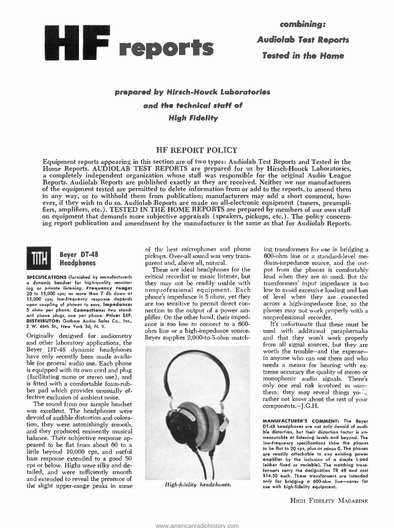
Originally designed for audiometry and other laboratory applications, the Beyer DT -48 dynamic headphones have only recently been made availa- ble for general audio use. Each phone is equipped with its own cord and plug (facilitating mono or stereo use), and is fitted with a comfortable foam -rub- ber pad which provides unusually ef- fective exclusion of ambient noise.
The sound from our sample headset was excellent. The headphones were devoid of audible distortion and colora- tion, they were astonishingly smooth, and they produced eminently musical balance. Their subjective response ap- peared to be flat from about 60 to a little beyond 10,000 cps, and useful bass response extended to a good 50 cps or below. Highs were silky and de- tailed, and were sufficiently smooth and extended to reveal the presence of the slight upper -range peaks in some
of the best microphones and phono pickups. Over -all sound was very trans- parent and, above all, natural.
These are ideal headphones for the critical recordist or music listener, but they may not be readily usable with nonprofessional equipment. Each phone's impedance is 5 ohms, yet they are too sensitive to permit direct con- nection to the output of a power am- plifier. On the other hand, their imped- ance is too low to connect to a 600 - ohm line or a high -impedance source. Beyer supplies 2,000- to -5-ohm match-
High -fidelity headphones.
ing transformers for use in bridging a 600 -ohm line or a standard -level me- dium- impedance source, and the out- put from the phones is comfortably loud when they are so used. But the transformers' input impedance is too low to avoid excessive loading and loss of level when they are connected across a high -impedance line, so the phones may not work properly with a nonprofessional recorder.
It's unfortunate that these must be used with additional paraphernalia and that they won't work properly from all signal sources, but they are worth the trouble -and the expense - to anyone who can use them and who needs a means for hearing with ex- treme accuracy the quality of stereo or monophonic audio signals. There's only one real risk involved in min,. them: they may reveal things yo:. rather not know about the rest of your components.- J.G.H.
MANUFACTURER'S COMMENT: The Beyer DT -48 headphones are not only devoid of audi- ble distortion, but their distortion factor is un- measurable at listening levels and beyond. The low- frequency specifications show the phones to be flat to 20 cps, plus or minus O. The phones are readily attachable to any existing power amplifier by the inclusion of a simple L -pad (either fixed or variable). The matching trans- formers carry the designation TR 48 and cost $14.50 each. These transformers are intended only for bridging a 600 -ohm line -never for use with high -fidelity equipment.
HIGH FIDELITY MAGAZINE
www.americanradiohistory.com
JA JV" /i
otham /Audio sales co. inc. 2 WEST 46th STREET, NEW YORK 36, NEW YORK
THE NEUMANN AM -32b MASTER STEREO DISK RECORDING LATHE
GENERAL:
It has been some time since the design of an entirely new disk lathe has come to the fore. Now with stereo disk placing even greater demands on the manufacturer - demands for quality and quantity - it is time to re- evaluate the entire line of equipment used in the production and reproduction of stereo- phonic records. One important link to date has been ignored: the disk cutting lathe itself. Reason for placing renewed emphasis on the lathe is the advent (or should we say "re- advent ") of vertical compliance in cartridges, which demands of the disk even more rumble -free performance than heretofore. Secondly, the complex excursions of the groove have made it necessary to reduce the amount of time possible on a disk, making an investigation into the possibilities of disk space conservation vital. Furthermore, since the hazards of Stereo are consider- ably more than double those of monophonic recording, further automation of the actual cutting process has become essential.
A. THE TURNTABLE UNIT - AM 32b:
The basic lathe bed is built up on a heavy cast iron base, standing on four rubber shock mountings. The turntable itself is of heavy cast iron, weigh- ing 65 lbs. Its edge is cast with three stroboscopic rings - one for each speed - which are illuminated by a small neon spotlight bulb for easy observation. The turntable is completely isolated from the drive below by means of an oil -filled coupling, preventing rumble and flutter from being transmitted from the drive. The turntable is driven solely by a film of oil between two walls of two concentric cylinders. Almost a pint of oil goes into this coupling. The lathe bed is of the slide type with two ball bearings riding the top of the bed to relieve the strain placed on the sled by the weight of the cutter suspension and cutterhead.
Directly beneath the lathe bed is a calibrated diameter scale on which are mounted the starting cams and end groove stop. Three cams, for 7 ", 10", and 12" disks are provided, the one to be used being raised into operating position. The end groove stop is adjustable to the three standard RIAA end groove diameters, and causes the cutterhead either to lift immediately (for eccentric grooves), or with a 1.25 revolution delay to provide a locked groove (now becom- ing standard for LP as well). The lead -screw engaging lever is interlocked in such a way that the cutter will lift at any time that it is not being driven by the lead- screw, making stylus catastrophies impossible.
www.americanradiohistory.com
B. THE DRIVE MOTOR UNIT - SM 8 /3A: Page 2
This motor, manufactured by LYREC of Copenhagen, Denmark, is unique in its field. It is of the synchronous type with motor RPM equal to disk RPM. A gear -like wheel, about 10 inches in diameter, rotates inside a similar inside gear in which, by means of a winding, a rotating magnetic field is set up. The motor must be started (for which a starting motor is mounted atop the unit) and requires a flywheel (the turntable) to continue "hunting" from one gear -tooth to the next. Since this type of motion has some inherent flutter, a second gear is placed next to the first, but out of phase. The winding for this gear is phase advanced by insertion of a condenser producing a 90 degree phase shift, and cutting the flutter in half. For each speed, 33, 45, and 78, there are two such gears and they are all arranged coaxially on the drive shaft. In this way, each speed has its own motor. Wow and flutter of the lathe is in the neighborhood of 0. 008% RMS total, at ALL speeds. The motor is connected to the turntable by a connecting rod with two simple rubber disk couplings. Alignment of the connecting rod is not critical. The connecting rod is extendable to suit any console height.
C. 16 -2/3 RPM CONVERTER - ZA 33:
This small 4" x 4" x 5" unit containing a selenium rectifier, reduces the 33 -1/3 RPM speed motor to 16 -2/3 by doubling the ripple of the rotating magnetic field. For experimental uses, this unit will also produce the half- speeds of 45 or 78 RPM, useful for cutting frequency response disks and the like. For those interested in the reverse cutting of disks, incidentally, the motor can, of course, rotate in either direction in synchronism, depending on the direction in which it is initially started.
D. 16 1/2" Vacuum -chuck Turntable - ZA 3:
This unit fits over the basic turntable of the AM 32b and provides vacuum hold -down for all size blanks from 10" to 17 -1/4 ". A disabling valve provides the correct group of holes for any given size lacquer disk, with vacuum, thus preventing air escape and hiss.
Eccentric Cutting: The vacuum hold -down turntable can be dis- placed by simple pressure against one side, so that eccentric and grooves can be cut right on the lathe itself. A calibrated stop sleeve which fits over the end groove stop pin makes it unnecessary to examine the meeting of the eccentric groove with the tail -out groove under a microscope; the meeting is accurate automatically.
E. THE CUTTERHEAD SUSPENSION - SA 32; Part of AM 32b:
All of the cutterhead connections and functions are accomplished by a rectangular device mounted on the lathe's transport sled. The cutter is plugged into this unit by means of a small metal plug attached to it, permitting exchange of cutters from monophonic to stereo without misalignment. The con- nections are made by means of two 6 -prong plugs on the suspension. These pro- vide the two drive signals, two feedback signals, and DC stylus heat. Both the heating current and the two input signals are switched off when the cutter is
www.americanradiohistory.com
Page 3
raised. A release solenoid immediately raises the cutterhead whenever the "stop" button is depressed, when the sled hits the end groove stop, or when the lead screw is disengaged.
A dash -pot at the front of the suspension is equipped with a per- forated piston. An adjustable shield over these perforations allows a wide range of damping effects without changing viscosity of fluid.
The wiring from the cutter is led concentrically through the pivot ball bearings to prevent any stiffness or resistance to free motion. The tilting mechanism to which the cutter is mounted is connected to a large moving coil system which, together with the depth -of -cut control provides electronic depth variation.
F. DEPTH -OF -CUT CONTROL PANEL - TE 2; Part of AM 32b:
Located on the base of the lathe bed is the depth -of -cut control panel. It supplies a DC current to the moving coil system in the cutter suspension which relieves cutterhead pressure on the disk. A simple potentiometer provides full range of cutting depth, which can be observed in the microscope while adjust- ment is made. A second, similar control pre -sets the increased depth generally used in lead in, lead out and spiraling grooves. A test button switches to the second pre -set control for proper adjustment prior to commencement of cutting operation. Two toggle switches permit automatic deepening of the grooves during spiraling, lead in or lead out, or disables it for any one of these functions.
G. THE PITCH CONTROL UNIT - VA 32a:
The pitch control and general control consolette is a separate piece of equipment, and is situated next to the lathe to its right. NO power or drive is taken from the turntable motor for any drive of the lead screw; the pitch drive is entirely self -contained, and is coupled to the lead screw by a four -way shock isolated coupling. The console mounts the following controls: motor stop and start; motor speed control selector; heated stylus control (D. C. ); stop; start; lead in; spiraling; lead out buttons and tally lights; heated stylus ammeter; micro- scope light switch; cutterhead pick up delay for concentric and groove; main pitch selection dial; and pitch control current meter. The depth of cut control current meter is mounted on the base of the lathe itself.
The pitch motor is connected by means of a belt and through an oil filled gear train and the flexible coupling to the lead screw. A copper disk on the shaft of this motor runs over the four poles of an electromagnet, in which a DC current produces a braking action which stabilizes the pitch motor's RPM. A second, identical motor is likewise belt connected to an overdrive in the gear train, and serves for speed up of pitch for lead in, spiraling, and lead out. It likewise has a stabilizing brake by means of which the lead in, spiraling and lead out pitch can be separately and accurately adjusted at each speed. The braking current on the pitch motor is approximately 100 ma, which is supplied from an internal recti- fier. The main pitch selector control which is calibrated from 54 to 475 lines /inch, is simply a powerstat controlling the AC voltage fed to the pitch drive motor.
www.americanradiohistory.com
Page 4
* H. THE AUTOMATIC PITCH AMPLIFIER - SV 32s:
In the rack space inside the base of the lathe are located three servo amplifiers required for stereodisk cutting control. The first of these is the SV 32s pitch control amplifier. A preview head is required for automatic control, and in this case, the head must be a stereo head. The signal from this head is fed to two tape playback amplifiers, and from there to a sum and difference trans- former converter.
In the 45/45 stereo system, the phasing is so arranged that the sum
of the two stereo signals forms the lateral -only component of the groove, while the difference of the signals is the purely vertical component. In order to sepa- rate the signals influencing the excursion of the stylus in a lateral plane, we must, therefore, add the two signals from the stereo preview head, and control with this sum the variation of pitch in order to attain maximum space utilization. This addition is now fed to the input of the pitch control amplifier.
In this amplifier, the signal is rectified and fed to an RC time constant circuit. A second rectifier leads to a second RC time constant circuit of shorter duration. A diode between the two RC circuits becomes conductive whenever the voltage of one of them falls below that of the other. This is so arranged that it will occur after one full revolution of the disk. Should no further signal be received from the preview head by that time, the resulting negative voltage is applied to the power output stage of the amplifier which delivers the necessary braking current needed by the pitch control motor, and that braking current, which was partially removed during the period of high input signal, is restored to normal, and the lead screw drive is again slowed down to the pitch adjusted on the main dial. The disk speed (time constant) as well as the pitch control range has to be adjusted on the amplifier. Since the pitch control is entirely electronic, it is fast acting, thus achieving optimum space conservation.
* I. THE DEPTH CONTROL AMPLIFIER - SV 32v:
The depth control amplifier SV 32v is in every detail identical to the pitch control unit. Its output, however, is fed to the solenoid in the cutter suspension, and produces there the varying relief of cutter pressure, acting against the weight and counterbalancing spring of the cutter. The time constants required are the same as in pitch control.
* J. THE INTEGRATION AMPLIFIER - SV 32t:
In lateral and vertical modulation, increased depth requires in- creased pitch, so that any deepening of the groove allowed by the depth control amplifier, must be translated in turn into increased pitch at the same time (but not conversely). The SV 32t integration amplifier does just that, by adding to the pitch control current whenever increased depth is called for. This unit is a simple recti- fier circuit without time constants, since these are already taken care of by the other two control units.
It has been shown over the past year and a half that this form of independent pitch and depth control can add up to 6 minutes to the playing time of one side of a 12" LP recording. Of course, as is always the case, recordings
www.americanradiohistory.com
Page 5
of a high dynamic range benefit most from such controls, while highly limited or compressed material gains almost nothing.
Each of the control amplifiers is equipped with a plug -in equalizer for RIAA equalization, which translates the RIAA pre -ehphasized velocity curve into its counterpart in stylus excursion. As such, both depth and pitch control are most active when low frequency signals are received, while high frequency sound of even the highest intensity produces practically no increased depth or pitch.
* Protected under one or more of the following German patents: 836, 116; 938, 586; 845, 413; 875, 732; 1, 013, 889. U. S. patents pending.
K. PHOTOELECTRIC AUTOMATION UNIT - ZA 34:
Each AM 32b Stereo Disk Mastering Lathe comes equipped with a unit for the complete automation of the mastering process. A photocell placed on the tape playback machine directly after the head assembly signals to this unit when- ever leader tape (or a light mark painted on the back of the tape at the end of each cut) comes by. On the unit itself, the operator has punched up on a series of 12 push buttons, the number of cuts the master is to have. On another row of 12 push buttons he selects the length of the spiral between cuts from 0. 5 to 5. 5 seconds in .5 second increments. The unit will then automatically signal to the lathe to spiral (with increased depth of cut) at the beginning of the first piece of leader. If desired, another button permits the lathe to spiral for the entire length of the leader tape, where such has been timed. As each cut is ended, a selector is stepped and the next numbered cut button lights up. At the last cut, a red lamp signals that the next leader or mark will produce the lead out spiral and either immediate cutter lift or concentric groove and lift.
L. THE MICROSCOPES - ZA 36:
A high power precision "Leitz Ultra Pak" microscope with concen- tric illumination and micrometer focusing, provides the clearest possible picture of the groove. It comes with multi -color light filters and blanking filters, making it possible to examine either half of the groove separately. The microscope is mounted at right angles to the disk surface for proper inspection, and moves exactly along its radius. A second, small microscope is attached to the cutterhead sus- pension unit and is transported with it, permitting observation of the last few grooves "standing still" as you cut. Lighting is also provided for this microscope. Both have reticle lines for calibration.
M. THE BUCHMANN MEYER LIGHT - Z 21:
One of the great aids to frequency response alignment is the Buchmann Meyer light; a parallel light source which is to be mounted on the ceiling to the left of the turntable, so as to throw a beam at the disk at a 45 degree angle. In this way, it is only necessary to cut a band of 1000 cycle tone, followed by one of 15 KC. Then, while observing the light band width of the 15 KC tone, the equali- zation is adjusted until the 1 KC and 15 KC widths are equal (equalization flat).
www.americanradiohistory.com
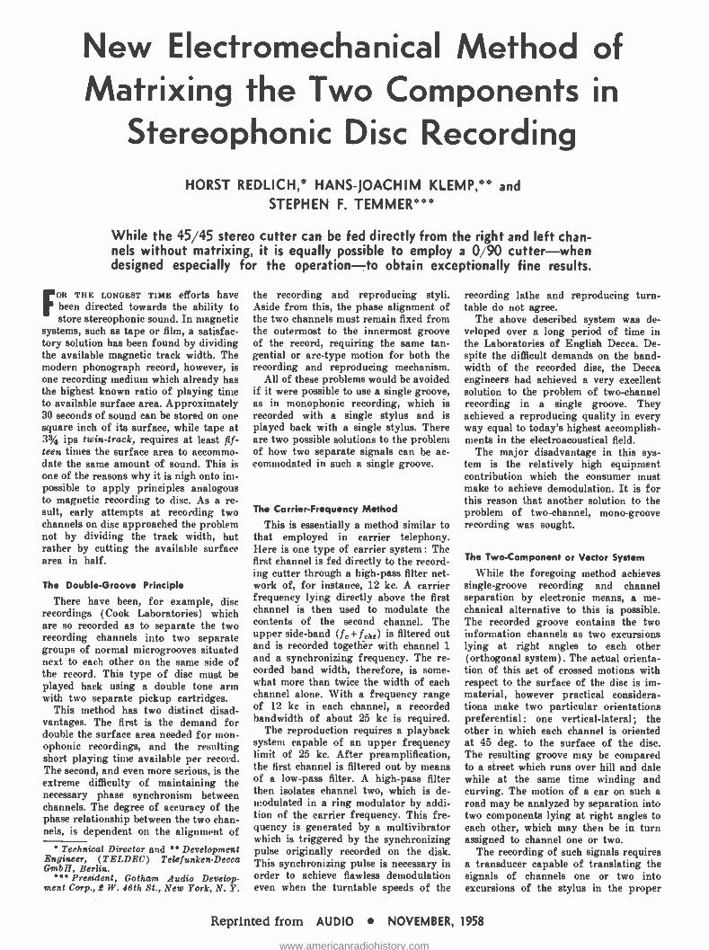
New Electromechanical Method of Matrixing the Two Components in
Stereophonic Disc Recording HORST REDLICH, HANS- JOACHIM KLEMP, and
STEPHEN F. TEMMER
While the 45 45 stereo cutter can be fed directly from the right and left chan- nels without matrixing, it is equally possible to employ a 0,%90 cutter -when designed especially for the operation -to obtain exceptionally fine results.
FOR THE LONGEST TIME efforts have been directed towards the ability to store stereophonic sound. In magnetic
systems, such as tape or film, a satisfac- tory solution has been found by dividing the available magnetic track width. The modern phonograph record, however, is one recording medium which already has the highest known ratio of playing time to available surface area. Approximately 30 seconds of sound can be stored on one square inch of its surface, while tape at 3% ips twin- track, requires at least fif- teen times the surface area to accommo- date the same amount of sound. This is one of the reasons why it is nigh onto im- possible to apply principles analogous to magnetic recording to disc. As a re- sult, early attempts at recording two channels on disc approached the problem not by dividing the track width, but rather by cutting the available surface area in half.
The Double- Groove Principle
There have been, for example, disc recordings (Cook Laboratories) which are so recorded as to separate the two recording channels into two separate groups of normal microgrooves situated next to each other on the same side of the record. This type of disc must be played back using a double tone arm with two separate pickup cartridges.
This method has two distinct disad- vantages. The first is the demand for double the surface area needed for mon- ophonic recordings, and the resulting short playing time available per record. The second, and even more serious, is the extreme difficulty of maintaining the necessary phase synchronism between channels. The degree of accuracy of the phase relationship between the two chan- nels, is dependent on the alignment of
Technical Director and Development Engineer, (TELDEC) Telefunken -Decca GmbH, Berlin.
President, Gotham Audio Develop- ment Corp., L W. 46th St., New York, N. Y.
the recording and reproducing styli. Aside from this, the phase alignment of the two channels must remain fixed from the outermost to the innermost groove of the record, requiring the same tan- gential or arc -type motion for both the recording and reproducing mechanism.
All of these problems would be avoided if it were possible to use a single groove, as in monophonic recording, which is recorded with a single stylus and is played back with a single stylus. There are two possible solutions to the problem of how two separate signals can be ac- commodated in such a single groove.
Th. Carrier -Frequency Method
This is essentially a method similar to that employed in carrier telephony. Here is one type of carrier system : The first channel is fed directly to the record- ing cutter through a high -pass filter net- work of, for instance, 12 kc. A carrier frequency lying directly above the first channel is then used to modulate the contents of the second channel. The upper side -band (fc +fdu) is filtered out and is recorded together with channel 1 and a synchronizing frequency. The re- corded band width, therefore, is some- what more than twice the width of each channel alone. With a frequency range of 12 kc in each channel, a recorded bandwidth of about 25 kc is required.
The reproduction requires a playback system capable of an upper frequency limit of 25 kc. After preamplification, the first channel is filtered out by means of a low -pass filter. A high -pass filter then isolates channel two, which is de- modulated in a ring modulator by addi- tion of the carrier frequency. This fre- quency is generated by a multivibrator which is triggered by the synchronizing pulse originally recorded on the disk. This synchronizing pulse is necessary in order to achieve flawless demodulation even when the turntable speeds of the
recording lathe and reproducing turn- table do not agree.
The above described system was de- veloped over a long period of time in the Laboratories of English Decca. De- spite the difficult demands on the band- width of the recorded disc, the Decca engineers had achieved a very excellent solution to the problem of two -channel recording in a single groove. They achieved a reproducing quality in every way equal to today's highest accomplish- ments in the electroacoustical field.
The major disadvantage in this sys- tem is the relatively high equipment contribution which the consumer must make to achieve demodulation. It is for this reason that another solution to the problem of two -channel, mono -groove recording was sought.
The Two -Component or Vector System
While the foregoing method achieves single- groove recording and channel separation by electronic means, a me- chanical alternative to this is possible. The recorded groove contains the two information channels as two excursions lying at right angles to each other (orthogonal system). The actual orienta- tion of this set of crossed motions with respect to the surface of the disc is im- material, however practical considera- tions make two particular orientations preferential : one vertical -lateral; the other in which each channel is oriented at 45 deg. to the surface of the disc. The resulting groove may be compared to a street which runs over hill and dale while at the same time winding and curving. The motion of a car on such a road may be analyzed by separation into two components lying at right angles to each other, which may then be in turn assigned to channel one or two.
The recording of such signals requires a transducer capable of translating the signals of channels one or two into excursions of the stylus in the proper
Reprinted from AUDIO NOVEMBER, 1958
www.americanradiohistory.com
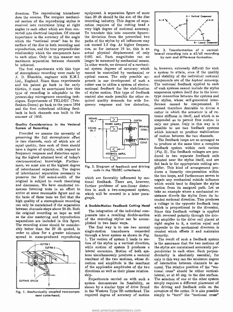
direction. The reproducing transducer does the reverse. The complex mechani- cal motion of the reproducing stylus is resolved into excursions lying at right angles to each other which are then con- verted into electrical impulses. Of utmost importance is the accuracy of the angle which the "motional cross" has to the surface of the disc in both recording and reproduction, and the true perpendicular relationship which the components have to each other. Only in this manner can maximum separation between channels be achieved.
The first experiments with this type of stereophonic recording were made by A. D. Blumlein, engineer with E.M.I. Ltd., England. Since these experiments and his patent go back to the early thirties, it must he ascertained how this type of recording is adaptable to the present -day microgroove recording tech- niques. Experiments of TELDEC (Tele- funken -Decca) go back to the years 1954 and the first cutterhead utilizing feed- back in both channels was built in the summer of 1955.
Quality Considerations in the Vectoral System of Recording
Provided we assume the necessity of preserving the full stereophonic effect in two channels, each of which are of equal quality, then each of them should have a degree of quality, with respect to frequency response and distortion equal- ing the highest attained level of today's electroacoustical knowledge. Further- more, we must aim at the highest degree of interchannel separation. The degree of interchannel separation necessary to preserve the full sound -width of the original is subject to much theorizing and discussion. We have conducted nu- merous listening tests in an effort to arrive at some reasonable figure and on the basis of these tests we feel that the high quality of a stereophonic recording can only be maintained if the separation between channels stays above 20 db. Both the original recording on tape as well as the disc mastering and reproduction separations are included in this figure. The recording alone should be consider- ably better than the 20 db quoted, in order to allow for a greater tolerance spread in mass- produced reproducing
Fig. 1. Mechanically coupled two- compo- nent cutterhead.
equipment. A separation figure of more than 30 db should be the aim of the disc recording industry. This degree of sepa- ration requires of the cutting head a very high degree of motional accuracy. To translate this into concrete figures: the deviation from the prescribed two paths of the stylus by all influences may not exceed 1.5 deg. At higher frequen- cies, as for instance 10 kc, this is an actual physical displacement of only 0.001 mil. Such magnitudes can no longer be measured by mechanical means. In other words, we demand of a mechani- cal system degrees of accuracy which cannot be controlled by mechanical or optical means. The only possible ap- proach in our development of such a cutter was to utilize a system of electro- motional feedback for the stabilization of stylus motion. This type of feedback control also made possible the other re- quired quality demands for wide fre- quency response and low distortion,
Fig. 2. Diagram of feedback and driving coils in the TELDEC cutterhead.
which are favorably influenced by mo- tional feedback. There are, however, further problems of non -linear distor- tion in such a two -component system, which will be covered in a later para- graph.
A Double -Motion Feedback Cutting Head
The integration of the individual com- ponents into a resulting double- motion of the recording stylus can be accom- plished in two basic ways.
The first way is to use two normal single- motion transducers connected through a lever system as shown in Fig. 1. The motion of system 1 leads to mo- tion of the stylus in a vertical direction, while motion of system 2 produces a lateral excursion. Motion of both sys- tems simultaneously produces a vectoral resultant of the two motions, whose di- rection and amplitude is the resultant of the applicable amplitudes of the two directions as well as their phase relation ship.
Experiments carried on with such a system demonstrate its feasibility, as shown by a similar type of drive found in the Westrea Type 3B cutterhead. The required degree of accuracy of motion
A-e \ - Vertical Component
Ae i i //\ / 4s
B - Lateral Component
ig. 3. Transformation of a vertical - lateral recording into a 45/45 recording
by sum and difference formation.
is, however, extremely difficult for such a system to attain, even if the quality and stability of the individual motional components are of the highest accuracy. The motional feedback applied to each of such systems cannot include the stylus suspension system itself due to the lever - type connection between the systems and the stylus, whose self- generated inter- ference cannot be compensated. It seemed therefore desirable to devise a cutter in which the armature is of ex- treme stiffness in itself, and which is so suspended as to permit free motion in only one plane. Only in this way is it possible to use two feedback systems which interact to produce stabilization of motion between the two channels.
The feedback loops are so arranged as to produce at the same time a complete feedback system within each motion (Fig. 2). The feedback voltages are pro- duced in two separate feedback coils situated near the stylus itself, and are fed back to the appropriate cutting am- plifier. This kind of arrangement pro- duces a linearity compensation within the two loops, and furthermore serves to negate any mechanical outside influence which would tend to displace the stylus motion from its assigned path. Let us take an example where a mechanical re- sistance diverts the stylus from its in- tended motional direction. This produces a voltage in the opposite feedback loop which is proportional to the diversion. Since this feedback voltage is applied with reversed polarity through the driv- ing amplifier to the drive coil placed at right angles to it, a motion equal and opposite to the mechanical diversion is created which offsets it and maintains linearity.
The result of such a feedback system is the assurance that the two motions of the stylus are maintained accurately per- pendicular to each other. Such perpen- dicularity is absolutely essential, for only in this way can the minimum degree of interaction between channels be as- sured. The relative position of the "mo- tional cross" should be either vertical - lateral, or at 45 deg. to the disc surface. The selection of one or the other system simply requires a different placement of the driving and feedback coils on the armature of the cutter. It is also possible simply to "turn" the "motional cross"
www.americanradiohistory.com
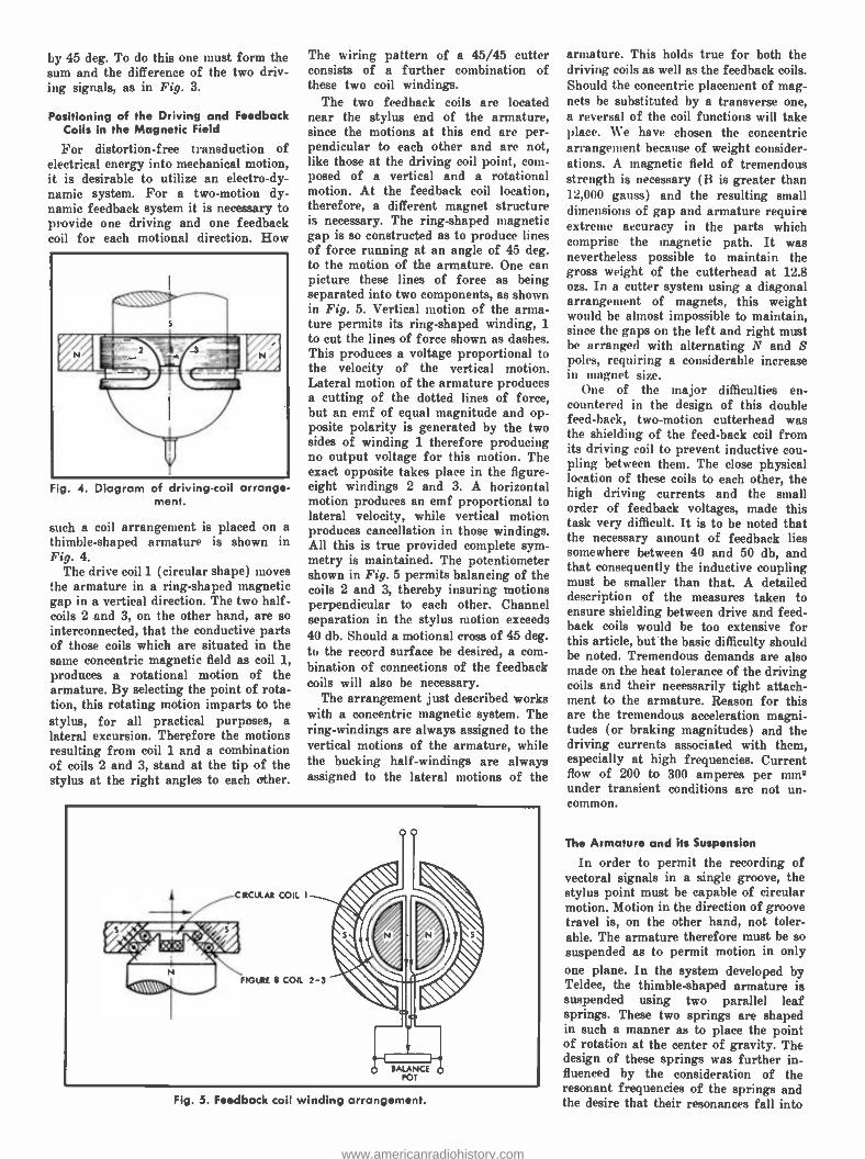
by 45 deg. To do this one must form the sum and the difference of the two driv- ing signals, as in Fig. 3.
Positioning of the Driving and Feedback Coils in the Magnetic Field
For distortion -free transduction of electrical energy into mechanical motion, it is desirable to utilize an electrody- namic system. For a two -motion dy- namic feedback system it is necessary to provide one driving and one feedback coil for each motional direction. How
(/ art. mihr
N
Fig. 4. Diagram of driving -coil arrange- ment.
such a coil arrangement is placed on a thimble -shaped armature is shown in Fig. 4.
The drive coil 1 (circular shape) moves the armature in a ring- shaped magnetic gap in a vertical direction. The two half - coils 2 and 3, on the other hand, are so interconnected, that the conductive parts of those coils which are situated in the same concentric magnetic field as coil 1, produces a rotational motion of the armature. By selecting the point of rota- tion, this rotating motion imparts to the stylus, for all practical purposes, a lateral excursion. Therefore the motions resulting from coil 1 and a combination of coils 2 and 3, stand at the tip of the stylus at the right angles to each other.
The wiring pattern of a 45/45 cutter consists of a further combination of these two coil windings.
The two feedback coils are located near the stylus end of the armature, since the motions at this end are per- pendicular to each other and are not, like those at the driving coil point, com- posed of a vertical and a rotational motion. At the feedback coil location, therefore, a different magnet structure is necessary. The ring -shaped magnetic gap is so constructed as to produce lines of force running at an angle of 45 deg. to the motion of the armature. One can picture these lines of force as being separated into two components, as shown in Fig. 5. Vertical motion of the arma- ture permits its ring -shaped winding, 1 to cut the lines of force shown as dashes. This produces a voltage proportional to the velocity of the vertical motion. Lateral motion of the armature produces a cutting of the dotted lines of force, but an emf of equal magnitude and op- posite polarity is generated by the two sides of winding 1 therefore producing no output voltage for this motion. The exact opposite takes place in the figure- eight windings 2 and 3. A horizontal motion produces an emf proportional to lateral velocity, while vertical motion produces cancellation in those windings. All this is true provided complete sym- metry is maintained. The potentiometer shown in Fig. 5 permits balancing of the coils 2 and 3, thereby insuring motions perpendicular to each other. Channel separation in the stylus motion exceeds 40 db. Should a motional cross of 45 deg. to the record surface be desired, a com- bination of connections of the feedback coils will also be necessary.
The arrangement just described works with a concentric magnetic system. The ring -windings are always assigned to the vertical motions of the armature, while the bucking half -windings are always assigned to the lateral motions of the
Fig. 5. Feedback coil winding arrangement.
armature. This holds true for both the driving coils as well as the feedback coils. Should the concentric placement of mag- nets be substituted by a transverse one, a reversal of the coil functions will take place. We have chosen the concentric arrangement because of weight consider- ations. A magnetic field of tremendous strength is necessary (B is greater than 12,000 gauss) and the resulting small dimensions of gap and armature require extreme accuracy in the parts which comprise the magnetic path. It was nevertheless possible to maintain the gross weight of the cutterhead at 12.8 ozs. In a cutter system using a diagonal arrangement of magnets, this weight would be almost impossible to maintain, since the gaps on the left and right must be arranged with alternating N and S poles, requiring a considerable increase in magnet size.
One of the major difficulties en- countered in the design of this double feed -back, two -motion cutterhead was the shielding of the feed -back coil from its driving coil to prevent inductive cou- pling between them. The close physical location of these coils to each other, the high driving currents and the small order of feedback voltages, made this task very difficult. It is to be noted that the necessary amount of feedback lies somewhere between 40 and 50 db, and that consequently the inductive coupling must be smaller than that. A detailed description of the measures taken to ensure shielding between drive and feed- back coils would be too extensive for this article, but the basic difficulty should be noted. Tremendous demands are also made on the heat tolerance of the driving coils and their necessarily tight attach- ment to the armature. Reason for this are the tremendous acceleration magni- tudes (or braking magnitudes) and the driving currents associated with them, especially at high frequencies. Current flow of 200 to 300 amperes per mm2 under transient conditions are not un- common.
The Armature and its Suspension
In order to permit the recording of vectoral signals in a single groove, the stylus point must be capable of circular motion. Motion in the direction of groove travel is, on the other hand, not toler- able. The armature therefore must be so suspended as to permit motion in only
one plane. In the system developed by Teldec, the thimble -shaped armature is suspended using two parallel leaf springs. These two springs are shaped in such a manner as to place the point of rotation at the center of gravity. The design of these springs was further in- fluenced by the consideration of the resonant frequencies of the springs and the desire that their resonances fall into
www.americanradiohistory.com
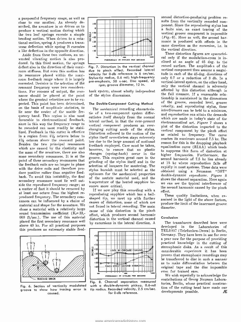
a purposeful frequency range, as well as close to one another. As already de- scribed, the armature is so driven as to produce a vertical motion during which the two leaf springs execute a simple bending motion. When driven to a rota- tional motion, spring A produces a trans- verse deflection while spring B executes a like deflection in the opposite direction.
Aside from these two motions, an un- wanted vibrating motion is also pro- duced. In this third motion, the springs deflect also in the direction of their maxi- mum stiffness. But even this motion has its resonance placed within the maxi- mum feedback range where it is largely corrected. Decisive in the selection of the resonant frequency were two considera- tions. For reasons of output, the reso- nance should be placed at the point where the greatest velocities are to be ex- pected. This point has been determined, on the basis of amplitude statistics, to lie near the center of the usable fre- quency band. This region is also most favorable to electromotional feedback, since in this way the frequency range to be recorded can most readily be stabi- lized. Feedback in this cutter is effective in a region from 41/2 octaves below to 41/2 octaves above the resonant point. Besides the two principal resonances which are caused by the elasticity and the mass of the armature, there are also some secondary resonances. It is at the point of these secondary resonances that the feedback coils are no longer in phase with the drive coils and therefore pro- duce positive rather than negative feed- back. To avoid this instability, the first secondary resonance must lie well out- side the reproduced frequency range; as a matter of fact it should be removed by at least one octave from the highest re- produced frequency. The secondary reso- nances can be influenced by a choice of material and shape for the armature. We chose a material with a relatively large sound transmission coefficient (K..= 33,- 000 ft /sec.). The use of this material placed the first secondary resonance well above 40 kc. For all practical purposes this produces an extremely stable feed-
Fig. 6. Section of vertically modulated groove to show how tracing error is
caused.
.10
0
10
-m _b -a _m
I
N. »s . . ..» FREQUENCY II. CYCLES PER SECOND
Fig. 7. Distortion in the vertical channel due to pinch effect. Recorded lateral velocity for 0 -db reference is 8 cm /sec. Stylus -tip radius, 0.6 mil; high- frequency pre- emphasis, 50 u-sec. Disc speed, 45
rpm; groove diameter, 12 in.
back system, almost wholly independent of the stylus dimensions.
The Double- Component Cutting Method
The mechanical recording characteris- tic of a two- component system differ- entiates itself sharply from the normal lateral method, in that the ever -present vertical component produces an ever - changing cutting mode of the stylus. Distortion referred to the motion of the stylus itself nevertheless stays extremely low due to the large amount of motional feedback employed. Care must be taken, however, to ensure that no plastic changes (spring -back) occur in the groove. This requires great care in the grinding of the stylus itself and in the selection of lacquers for mastering. The stylus burnish must be selected as the optimum for the mechanical properties of the acetate material used, and the temperature of the heated sapphire be- comes more critical.
If we now play this recording with a reproducing sapphire which has a ball - shaped tip, we meet up with further causes of distortion, some of which are not found in lateral recording. The main cause of this distortion is the pinch effect, which produces second harmonic distortion in the vertical channel caused by excursions in the lateral direction. A
10 0
Io
e A LEVEL IN OPPOSITE CHANNEL
c-= :.31.b
o-,- _to - P
o- . NCH EFFECT SECOND
4. HAR C Ì
NO
FREQUENCY
.
I... Moo
IN CYCLES FYI EECOND
Fig. 8. Channel separation measured with a double- dynamic pickup, 0.6 -mil tip radius. Recorded velocity, 2.5 cm /sec.
for 0 -db reference.
second distortion- producing problem re- sults from the vertically recorded com- ponent. Since the reproducing stylus has a finite size, an exact tracing of the vertical groove component is impossible (Fig.. 6). Here as well, the second har- monic is produced with effects in the same direction as the excursion, i.e. in the vertical direction.
These distortion figures are symmetri- cal only if the modulation -cross is in- clined at an angle of 45 deg. to the record surface. The amplitudes of the vertical component then assume a magni- tude in each of the 45 -deg. directions of only 0.7 or a reduction of 3 db. In a vertical- lateral system, on the other hand, only the vertical channel is adversely affected by this distortion although in the full measure. If a reasonable rela- tionship is maintained in the dimensions of the groove, recorded level, groove velocity, and reproducing stylus, these interferences can be held to a minimum, and reproduction can attain the demands which are made in today's state of the electroacoustical art. Figure 7 shows a plot of the distortion imparted to the vertical component by the pinch effect as related to frequency. The curve reaches its maximum around 7.5 kc. The reason for this is the dropping playback equalization curve (RIAA) which tends to suppress this form of distortion at higher frequencies. Furthermore, the second harmonic of 7.5 kc lies already at 15 kc where reproduction falls off rapidly in most systems. These data were obtained using a Neumann "DST" double- dynamic reproducer. Figure 8 shows the channel separation. Here again we can see the typical interference of the second harmonic caused by the pinch effect.
These quality limitations, when ex- amined in the light of the above factors, produce the limit of the innermost groove diameter.
Conclusion
The transducers described here were developed in the Laboratories of TELDEC (Telefunken -Decca) in Berlin, Germany. They have been in use for over a year now for the purpose of providing practical knowledge in the cutting of stereophonic disks. As a result of this considerable experience it has been proven that stereophonic recordings may be transferred to disc in such a manner as to make differentiation between the original tape and the disc impossible even for trained ears.
We wish especially to acknowledge the contributions of Georg Neuman Labora- tories, Berlin, whose practical construc- tion of the cutting head have made our developments possible. Æ
www.americanradiohistory.com
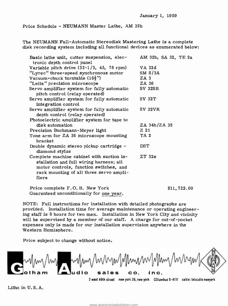
January 1, 1959
Price Schedule - NEUMANN Master Lathe, AM 32b
The NEUMANN Full- Automatic Stereodisk Mastering Lathe is a complete disk recording system including all functional devices as enumerated below:
Basic lathe unit, cutter suspension, elec- AM 32b, SA 32, TE 2a tronic depth control panel
Variable pitch drive (33 -1 /3, 45, 78 rpm) VA 32d "Lyrec" three -speed synchronous motor SM 8/3A Vacuum -chuck turntable (162 ") ZA 3
"Leitz" precision microscope ZA 36 Servo amplifier system for fully automatic SV 32SR
pitch control (relay operated) Servo amplifier system for fully automatic SV 32T
integration control Servo amplifier system for fully automatic SV 32VR
depth control (relay operated) Photoelectric amplifier system for tape to
disk automation ZA 34b /ZA 35 Precision Buchmann -Meyer light Z 21 Tone arm for ZA 36 microscope mounting TA 2
bracket Double dynamic stereo pickup cartridge - DST
diamond stylus Complete machine cabinet with suction in- ZT 32s
stallation and full wiring harness; all motor controls, function switches, and rack mounting of all three servo ampli- fiers
Price complete F.O. B. New York $11, 722.00 Guaranteed unconditionally for one year.
NOTE: Full instructions for installation with detailed photographs are provided. Installation time for average maintenance or operating engineer- ing staff is 8 hours for two men. Installation in New York City and vicinity will be supervised by a member of our staff. A charge for out -of- pocket expenses only is made for our installation supervision anywhere in the Western Hemisphere.
Price subject to change without notice.
RIVill otham udio sales co. inc. 2 west 46th street new york 36, new york COlumbus 5-4111 cable: telaudio newyork
iiiiiiimovrn
Litho in U.S. A.
www.americanradiohistory.com
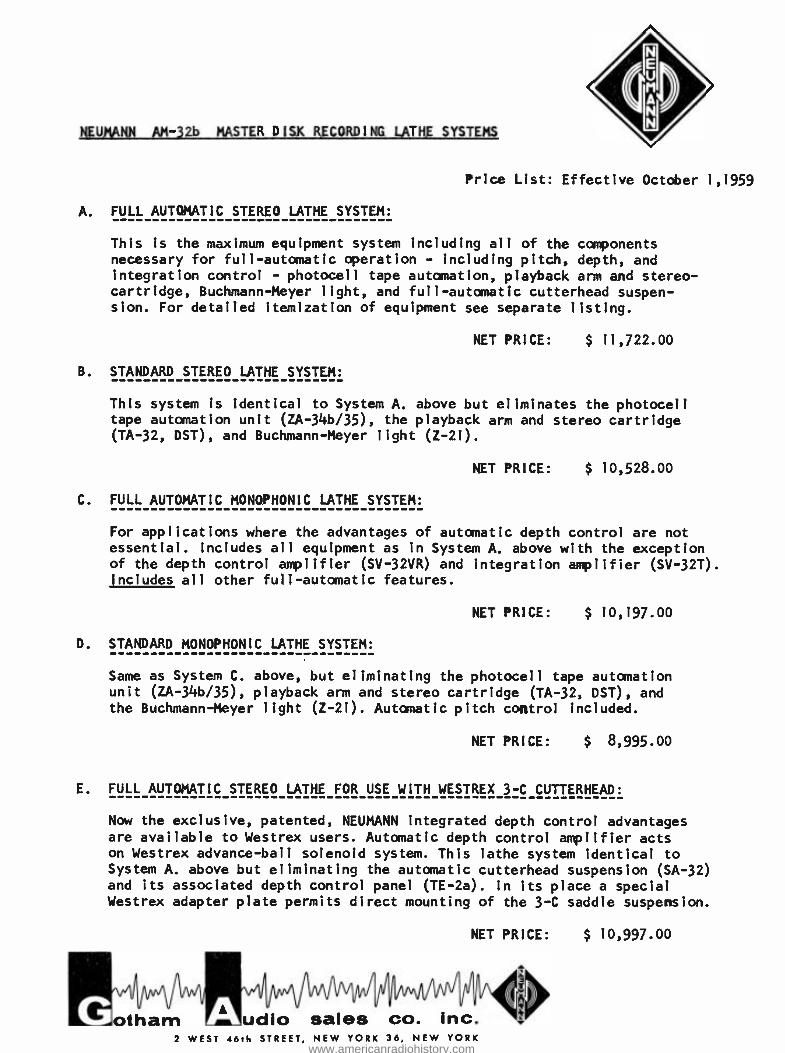
NEUMANN AM -32b MASTER DISK RECORDING LATHE SYSTEMS
Price List: Effective October 1,1959
A. FULL AUTOMATIC STEREO LATHE SYSTEM:
This is the maximum equipment system including all of the components necessary for full -automatic operation - including pitch, depth, and integration control - photocell tape automation, playback arm and stereo - cartridge, Buchmann -Meyer light, and full -automatic cutterhead suspen- sion. For detailed itemization of equipment see separate listing.
NET PRICE: $ 11,722.00
B. STANDARD STEREO LATHE SYSTEM:
This system is identical to System A. above but eliminates the photocell tape automation unit (ZA- 34b/35), the playback arm and stereo cartridge (TA -32, DST), and Buchmann -Meyer light (Z -21).
NET PRICE: $ 10,528.00
C. FULL AUTOMATIC MONOPHONIC LATHE SYSTEM:
For applications where the advantages of automatic depth control are not essential. Includes all equipment as in System A. above with the exception of the depth control amplifier (SV -32VR) and integration amplifier (SV -32T). Includes all other full -automatic features.
NET PRICE: $ 10,197.00
D. STANDARD MONOPHONIC LATHE SYSTEM:
Same as System C. above, but eliminating the photocell tape automation unit (ZA- 34b/35), playback arm and stereo cartridge (TA -32, DST), and the Buchmann -Meyer light (Z -21). Automatic pitch control included.
NET PRICE: $ 8,995.00
E. FULL AUTOMATIC STEREO LATHE FOR USE WITH WESTREX 3 -C CUTTERHEAD:
Now the exclusive, patented, NEUMANN integrated depth control advantages are available to Westrex users. Automatic depth control amplifier acts on Westrex advance -ball solenoid system. This lathe system identical to System A. above but eliminating the automatic cutterhead suspension (SA -32) and its associated depth control panel (TE -2a). In its place a special Westrex adapter plate permits direct mounting of the 3 -C saddle suspension.
NET PRICE: $ 10,997.00
otham udio sales co. inc. 2 WEST 46th STREET, NEW YORK 36, NEW YORK
www.americanradiohistory.com
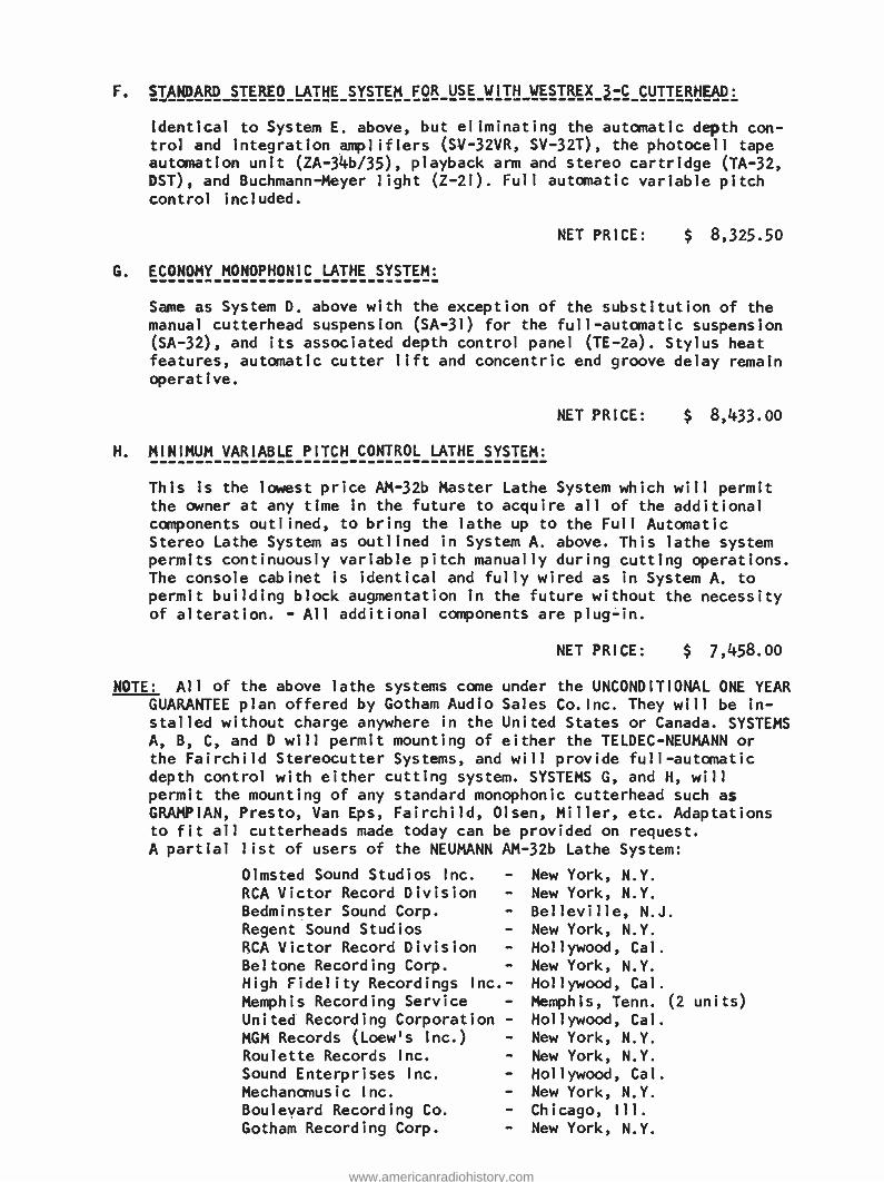
F. STANDARD STEREO LATHE SYSTEM FOR USE WITH WESTREX 3 -C CUTTERHEAD:
Identical to System E. above, but eliminating the automatic depth con- trol and integration amplifiers (SV -32VR, SV -32T), the photocell tape automation unit (ZA- 34b/35), playback arm and stereo cartridge (TA -32, DST), and Buchmann -Meyer light (Z -21). Full automatic variable pitch control included.
NET PRICE:
G. ECONOMY MONOPHONIC LATHE SYSTEM:
$ 8,325.50
Same as System D. above with the exception of the substitution of the
manual cutterhead suspension (SA -31) for the full -automatic suspension (SA -32), and its associated depth control panel (TE -2a). Stylus heat features, automatic cutter lift and concentric end groove delay remain operative.
NET PRICE: $ 8,433.00
H. MINIMUM VARIABLE PITCH CONTROL LATHE SYSTEM:
This is the lowest price AM -32b Master Lathe System which will permit the owner at any time in the future to acquire all of the additional components outlined, to bring the lathe up to the Full Automatic Stereo Lathe System as outlined in System A. above. This lathe system permits continuously variable pitch manually during cutting operations. The console cabinet is identical and fully wired as in System A. to
permit building block augmentation in the future without the necessity of alteration. - All additional components are plug -in.
NET PRICE: $ 7,458.00
NOTE: All of the above lathe systems come under the UNCONDITIONAL ONE YEAR GUARANTEE plan offered by Gotham Audio Sales Co.Inc. They will be in-
stalled without charge anywhere in the United States or Canada. SYSTEMS A, B, C, and D will permit mounting of either the TELDEC -NEUMANN or the Fairchild Stereocutter Systems, and will provide full -automatic depth control with either cutting system. SYSTEMS G, and H, will
permit the mounting of any standard monophonic cutterhead such as GRAMPIAN, Presto, Van Eps, Fairchild, Olsen, Miller, etc. Adaptations to fit all cutterheads made today can be provided on request. A partial list of users of the NEUMANN AM -32b Lathe System:
Olmsted Sound Studios Inc. -
RCA Victor Record Division -
Bedminster Sound Corp. -
Regent Sound Studios -
RCA Victor Record Division -
Beltone Recording Corp. -
High Fidelity Recordings Inc. -
Memphis Recording Service -
United Recording Corporation -
MGM Records (Loew's Inc.) -
Roulette Records Inc. -
Sound Enterprises Inc. -
Mechanornus i c Inc. -
Boulevard Recording Co. -
Gotham Recording Corp. -
New York, N.Y.
New York, N.Y.
Belleville, N.J
New York, N.Y.
Hollywood, Cal.
New York, N.Y.
Hollywood, Cal.
Memphis, Tenn. (2 units)
Hollywood, Cal.
New York, N.Y.
New York, N.Y.
Hollywood, Cal.
New York, N.Y.
Chicago, Ill.
New York, N.Y.
www.americanradiohistory.com
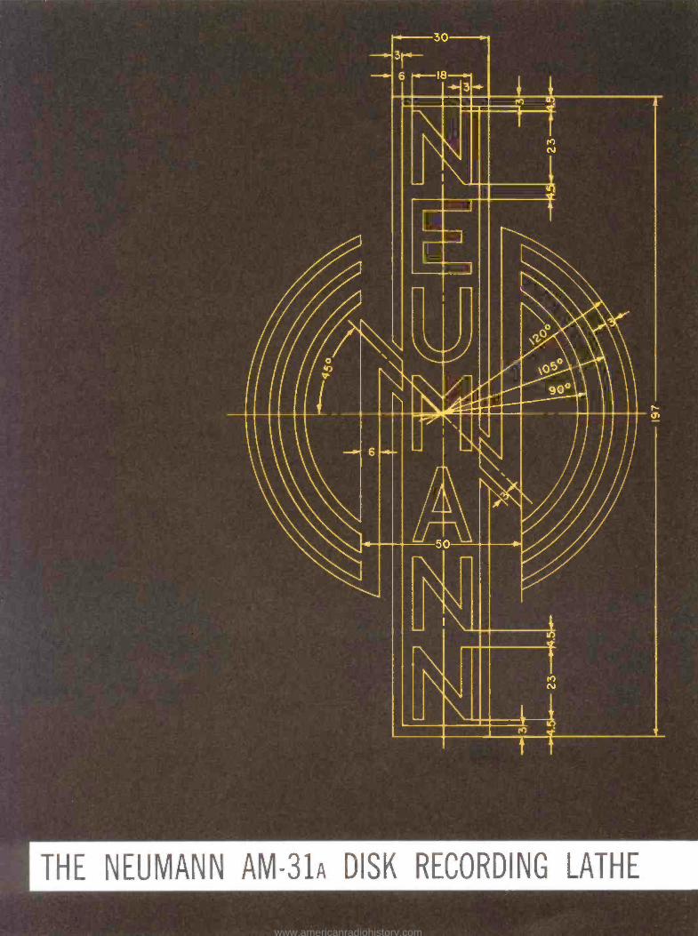
I THE NEUMANN AM -31a DISK RECORDING LATHE
www.americanradiohistory.com
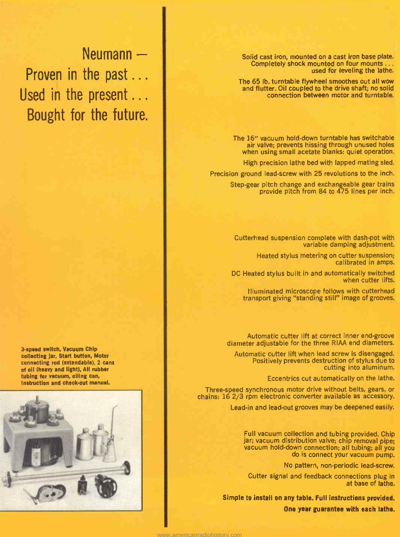
Neumann - Proven in the past...
Used in the present ... Bought for the future.
3 -speed switch, Vacuum Chip collecting jar, Start button, Motor connecting rod (extendable), 2 cans of oil (heavy and light), All rubber tubing for vacuum, oiling can, Instruction and check -out manual.
Solid cast iron, mounted on a cast iron base plate. Completely shock mounted on four mounts ...
used for leveling the lathe.
The 65 lb. turntable flywheel smoothes out all wow and flutter. Oil coupled to the drive shaft; no solid
connection between motor and turntable.
The 16" vacuum hold -down turntable has switchable air valve; prevents hissing through unused holes
when using small acetate blanks: quiet operation.
High precision lathe bed with lapped mating sled.
Precision ground lead -screw with 25 revolutions to the inch.
Step -gear pitch change and exchangeable gear trains provide pitch from 84 to 475 lines per inch.
Cutterhead suspension complete with dash -pot with variable damping adjustment.
Heated stylus metering on cutter suspension; calibrated in amps.
DC Heated stylus built in and automatically switched when cutter lifts.
Illuminated microscope follows with cutterhead transport giving "standing still" image of grooves.
Automatic cutter lift at correct inner end -groove diameter adjustable for the three RIAA end diameters.
Automatic cutter lift when lead screw is disengaged. Positively prevents destruction of stylus due to
cutting into aluminum.
Eccentrics cut automatically on the lathe.
Three -speed synchronous motor drive without belts, gears, or chains: 16 2/3 rpm electronic converter available as accessory.
Lead -in and lead -out grooves may be deepened easily.
Full vacuum collection and tubing provided. Chip jar; vacuum distribution valve; chip removal pipe; vacuum hold -down connection; all tubing; all you
do is connect your vacuum pump.
No pattern, non -periodic lead- screw.
Cutter signal and feedback connections plug in at base of lathe.
Simple to install on any table. Full instructions provided.
One year guarantee with each lathe.
www.americanradiohistory.com
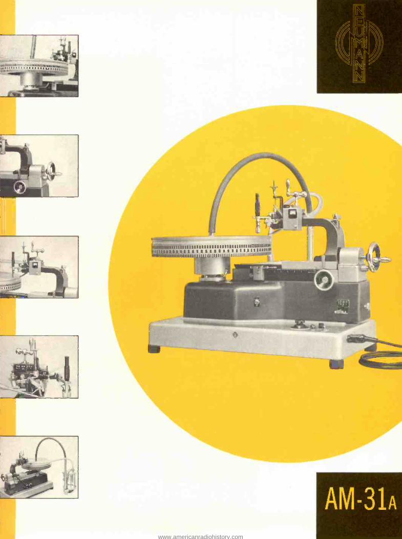
t
MUM UMW
I I u u u u 1U01
11111llID1t
r
AM -31n
www.americanradiohistory.com
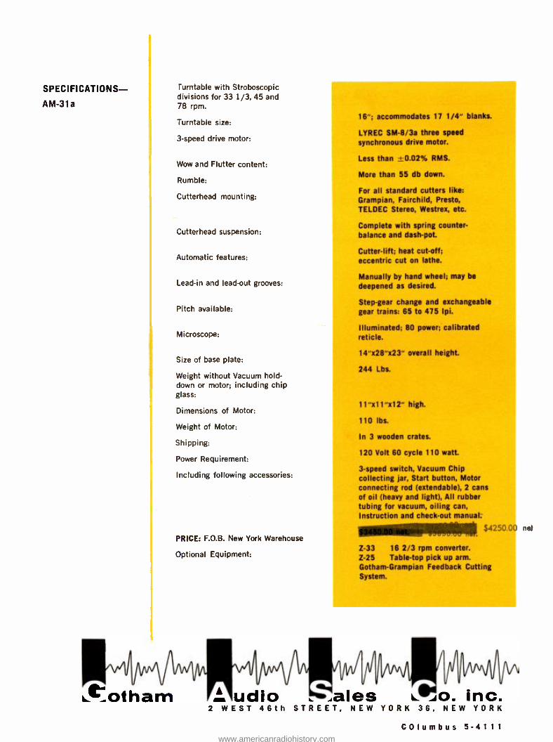
SPECIFICATIONS-
AM-31a
turntable with Stroboscopic divisions for 33 1/3, 45 and 78 rpm.
Turntable size:
3 -speed drive motor:
Wow and Flutter content:
Rumble:
Cutterhead mounting:
Cutterhead suspension:
Automatic features:
Lead -in and lead -out grooves:
Pitch available:
Microscope:
Size of base plate:
Weight without Vacuum hold - down or motor; including chip glass:
Dimensions of Motor:
Weight of Motor:
Shipping:
Power Requirement:
Including following accessories:
PRICE: F.O.B. New York Warehouse
Optional Equipment:
16 "; accommodates 17 1/4" blanks.
LYREC SM -8/3a three speed synchronous drive motor.
Less than , 0.02% RMS.
More than 55 db down.
For all standard cutters like: Grampian, Fairchild, Presto, TELDEC Stereo, Westrex, etc.
Complete with spring counter- balance and dash -pot.
Cutter -lift; heat cut -off; eccentric cut on lathe.
Manually by hand wheel; may be
deepened as desired.
Step -gear change and exchangeable gear trains: 65 to 475 Ipi.
Illuminated; 80 power; calibrated reticle.
14" x28"x23" overall height.
244 Lbs.
11 "x11 "x12" high.
110 lbs.
In 3 wooden crates.
120 Volt 60 cycle 110 watt.
3 -speed switch, Vacuum Chip collecting jar, Start button, Motor connecting rod (extendable), 2 cans of oil (heavy and light), All rubber tubing for vacuum, oiling can, Instruction and check -out manual. amemplops j4250.00
Z -33 16 2/3 rpm converter. Z -25 Table -top pick up arm. Gotham -Grampian Feedback Cutting System.
Pl/IAN udio !+.ales :o. inc.
2 W E S T 46 th S T R E E T , N E W Y O R K 36, N E W Y O R K
COlumbus 5-41 1 1
net
www.americanradiohistory.com
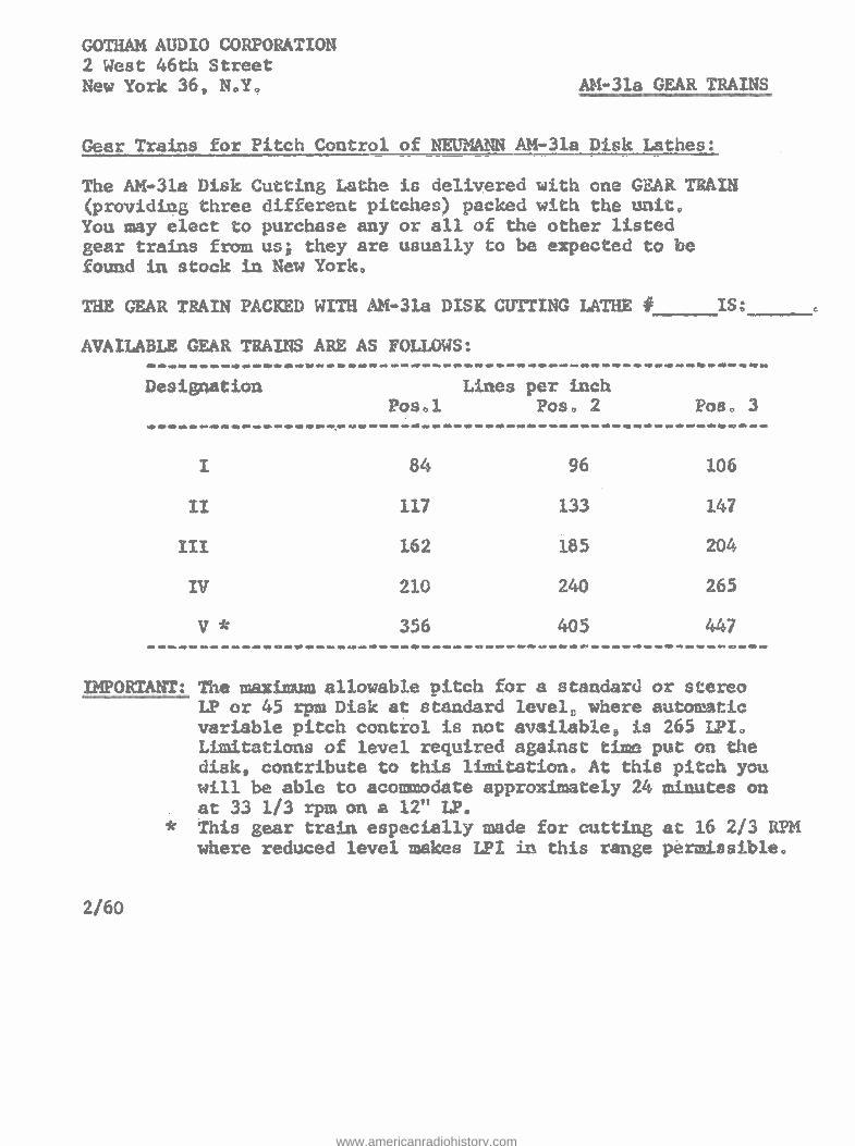
GOTHAM AUDIO CORPORATION 2 West 46th Street New York 36, N.Y. AM -31a GEAR TRAINS
Gear Trains for Pitch Control of NEUMANN AM -31a Disk Lathes:
The AM -31a Disk Cutting Lathe is delivered with one GEAR TRAIN (providing three different pitches) packed with the unit. You may elect to purchase any or all of the other listed gear trains from us; they are usually to be expected to be found in stock in New York.
THE CZAR TRAIN PACKED WITH AM.-313 nISy. CUTTING LATHE ñ TS
AVAILABLE GEAR TRAINS ARE AS FOLLOWS:
Designation Pos,l
Lines per inch Pos, 2 Pot 3
i 84 96 106
11 117 133 147
1I1 162 185 204
IV 210 240 265
* 3.56 405 447
I E'0I ANT: The maximum allowable pitch for a standard or stereo LP or 45 rpm Disk at standard level, where automatic variable pitch control is not avai1ab1e, is 265 LPI, Limitations of level required against time put on the disk, contribute to this limitation. At this pitch you will be able to acommodate approximately 24 minutes on at 33 1/3 rpm on a 12" LP.
* This gear train especially made for cutting at 16 2/3 RPH where reduced level makes LPI in this range permissible.
2/60
www.americanradiohistory.com
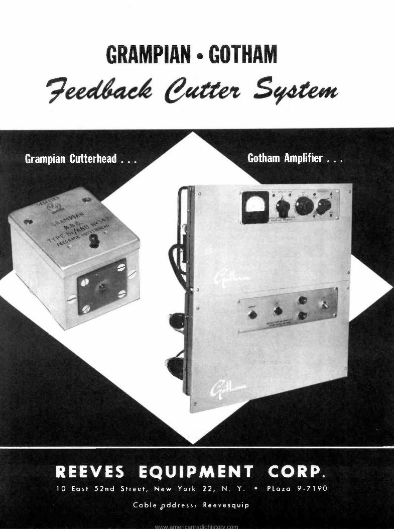
GRAMPIAN GOTHAM
9e;dead e4ee Sy¢teeu
REEVES EQUIPMENT CORP. 10 East 52nd Street, New York 22, N. Y. Plaza 9 -7190
Cable address: Reevesquip
www.americanradiohistory.com
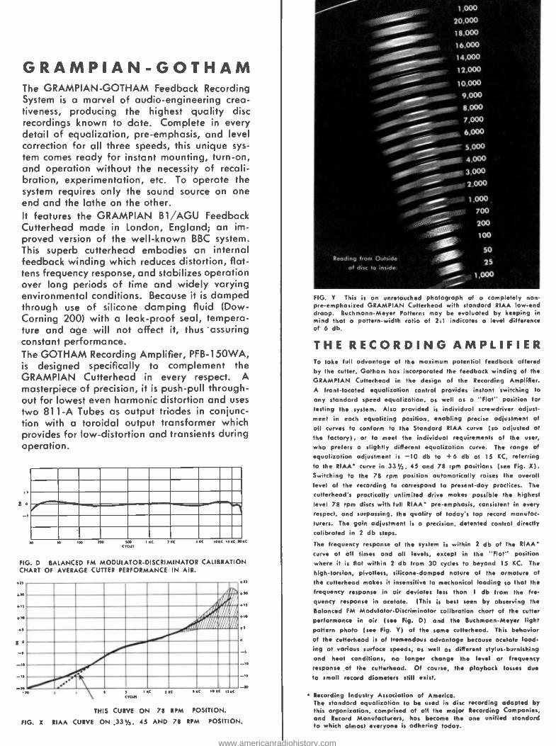
GRAMPIAN -GOTHAM The GRAMPIAN -GOTHAM Feedback Recording System is a marvel of audio -engineering crea- tiveness, producing the highest quality disc recordings known to date. Complete in every detail of equalization, pre- emphasis, and level correction for all three speeds, this unique sys- tem comes ready for instant mounting, turn -on, and operation without the necessity of recali- bration, experimentation, etc. To operate the system requires only the sound source on one end and the lathe on the other. It features the GRAMPIAN B1 /AGU Feedback Cutterhead made in London, England; an im- proved version of the well -known BBC system. This superb cutterhead embodies an internal feedback winding which reduces distortion, flat- tens frequency response, and stabilizes operation over long periods of time and widely varying environmental conditions. Because it is damped through use of silicone damping fluid (Dow - Corning 200) with a leak -proof seal, tempera- ture and age will not affect it, thus assuring constant performance. The GOTHAM Recording Amplifier, PFB- 150WA, is designed specifically to complement the GRAMPIAN Cutterhead in every respect. A masterpiece of precision, it is push -pull through- out for lowest even harmonic distortion and uses two 811-A Tubes as output triodes in conjunc- tion with a toroidal output transformer which provides for low- distortion and transients during operation.
E a
sao xc caes
s KC 5 K lost n < »u
FIG. D BALANCED FM MODULATOR- DISCRIMINATOR CALIBRATION CHART OF AVERAGE CUTTER PERFORMANCE IN AIR.
os
ao
+5
8 o
io
-U
}'/..
A
w
s
a
s
S
` IS r -x
tars C rxc SIM ,o C ur<
THIS CURVE ON 78 RPM POSITION.
FIG. X RIAA CURVE ON _33 s/s, 45 AND 78 RPM POSITION.
1,000
20,000
18,000
16,000
14,000
12,000
10,000
8,000
7,000 _ 6,000
s,0oo
4,000
3,000
-.1.1g 2'000
Reading from Outside of disc to inside:
1,000
700
200
100
50
25
1,000
FIG. Y This is on unretouched photogroph of a completely non -
pre- emphasized GRAMPIAN Cutterhead with standard RIAA lowend droop. Buchmann -Meyer Patterns may be evaluated by keeping in mind that a pattern -width ratio of 2:1 indicates a level difference of 6 db.
THE RECORDING AMPLIFIER To take full advantage of the maximum potential feedback offered by the cutter, Gotham has incorporated the feedback winding of the
GRAMPIAN Cutterhead in the design of the Recording Amplifier. A front- located equalization control provides instant switching to
any standard speed equalization, as well as a "Flat" position for fasting the system. Also provided is individual screwdriver adjust-
ment in each equalizing position, enabling precise adjustment of
all curves to conform to the Standard RIAA curve (so adjusted at the factory), or to meet the individual requirements of the user,
who prefers a slightly different equalization curve. The range of equalization adjustment is -10 db to +6 db at 15 KC, referring to the RIAA' curve in 33s /z, 45 and 78 rpm positions (see Fig. X). Switching to the 78 rpm position automatically raises the overall level of the recording to correspond to present -day practices. The
cutterhead's practically unlimited drive makes possible the highest level 78 rpm discs with full RIAA preemphasis, consistent in every respect, and surpassing, the quality of today's top record manufac- turers. The gain adjustment is a precision, detented control directly calibrated in 2 db steps.
The frequency response of the system is within 2 db of the RIAA curve at all times and all levels, except in the "Floc" position where it is flot within 2 db from 30 cycles to beyond 15 KC. The
high- torsion, pivolless, silicone- damped nature of the armature of
the culterheod makes it insensitive lo mechanical loading so that the
frequency response in air deviates less than 1 db from the fre-
quency response in acetate. (This is best seen by observing the
Balanced FM Modulator- Discriminator calibration chart of the cutter
performance in air (see Fig. D) and the Buchmann -Meyer light pattern photo (see Fig. Y) of the same cutterhead. This behavior of the cutterheod is of tremendous advantage because ocelote load- ing at various surface speeds, as well as different stylus- burnishing and heal conditions, no longer change the level or frequency response of the cutterhead. Of course, the playback losses due
to small record diameters still exist.
Recording Industry Association of America. The standard equalization to be used in disc recording adapted by this organization, comprised of all the major Recording Companies, and Record Manufacturers, has become the one unified standard to which almost everyone is adhering today.
www.americanradiohistory.com
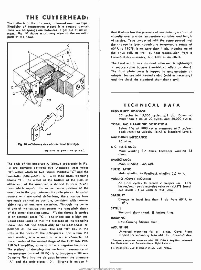
THE CUTTERHEAD: The Cutter is of the iron vane, balanced armature type. Simplicity of construction makes it a rugged device; there are no springs nor balances to get out of adjust- ment. Fig. 10 shows a cutaway view of the essential parts of the head.
Reprinted by permission of B.B.C.
The ends of the armature A (shown separately in Fig.
10 are clamped between two U- shaped steel yokes "B ", within which lie two Ticonal magnets "C" and the laminated pole -pieces "D ", with their brass clamping blocks "E ". The metal at the bottom of the slots at either end of the armature is shaped to form torsion bars which support the active center portion of the armature in the gap between the pole pieces. To avoid trouble with non -axial deflections, these torsion bars are made as short as possible, consistent with reason- able stress at maximum excursion. Through the center of one of the torsion bars passes the long plain shank of the cutter clamping screw "F "; the thread is carried in an external block "G ". The shank has a high tor- sional compliance so that the presence of the clamping screw does not add appreciably to the mechanical im-
pedance of the armature. The coil "H" lies in the slots in the faces of the pole -pieces, and within the main winding is a second coil which is connected to the cathodes of the second stage of the GOTHAM PFB-
150 WA amplifier, so as to provide negative feedback. The method of damping the mechanical resonance of the armature (around 10 KC) is to introduce a Silicone Damping Fluid into the air gaps between the armature "A" and the pole -pieces "D ". Silicone is unique in
that it alone has the property of maintaining a constant viscosity over a wide temperature variation and length of service. Tests conducted with the cutter proved that the change in level covering a temperature range of 60 °F. to 110 °F. is no more than 1 db. Heating up of the drive coil, as well as heat transmission from a
Thermo -Stylus assembly, had little or no effect.
The head will fit any standard lathe and is lightweight to reduce cutter bounce (marbleized effect on discs). The front plate cover is tapped to accommodate an adapter for use with heated stylus (sold as necessary) and the chuck fits standard short -shank styli.
TECHNICAL DATA FREQUENCY RESPONSE
30 cycles to 15,000 cycles ±2 db. Down no more than 4 db at 20 cycles and 20,000 cycles.
TOTAL RMS HARMONIC DISTORTION Below 1% at 1000 cycles measured at 7 cm /sec. peak recorded velocity (NARTB Standard level).
MATCHING IMPEDANCE 16 ohms.
D.C. RESISTANCE
Main winding 3.7 ohms, Feedback winding 23 ohms.
INDUCTANCE Main winding 1.65 MH.
TURNS RATIO
Main winding to Feedback winding 2:5 to 1.
*AUDIO POWER REQUIRED
At 1000 cycles to record 7 cm /per sec. (2% inches /sec.) peak recorded velocity (NARTB Stand- ard Level) - 1.26 watts or ±31 dbm.
STABILITY
Change in level less than 1 db from 60 °F. to 110 °F.
STYLUS
Standard short shank % inches long.
DAMPING Dow- Corning Silicone Fluid.
MOUNTING Universal mounting for all lathes. Cover Plate tapped for mounting Fairchild Hot Thermo -Stylus.
'Frequency response measured with PFB150WA Amplifier, balanced FM Modulator, and BuckmanMeyer Light Pattern.
FM Modulator, and Buchmonn -Meyer Light Pattern.
www.americanradiohistory.com
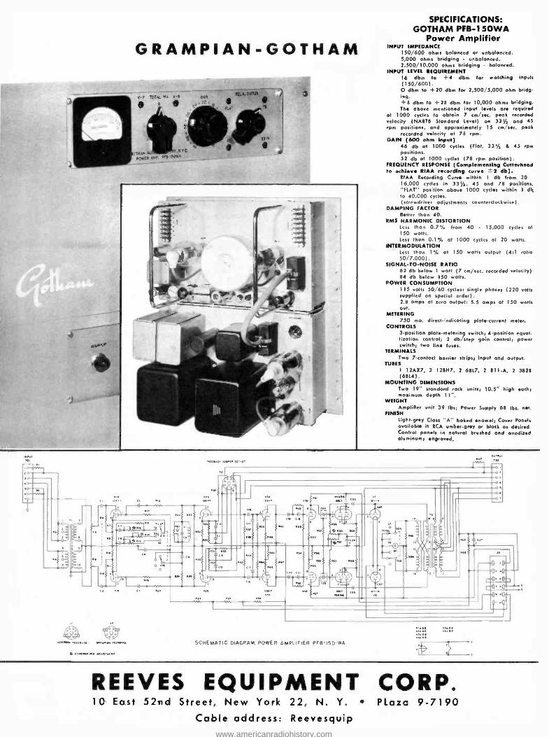
GRAMPIAN -GOTHAM
r:.+. ara i 3
SPECIFICATIONS: GOTHAM PFB -150WA
Power Amplifier INPUT IMPEDANCE
150, 600 ohms balanced or unbalanced. 5,000 ohms bridging unbalanced. 2,500/10,000 ohms bridging balanced.
INPUT LEVEL REQUIREMENT 16 dbm to +4 dbm for matching inputs (150 600). O dbm to +20 dbm for 2,500/5,000 ohm bridg- ing. +8 dbm to +28 dbm for 10,000 ohms bridging. The above mentioned input levels ore required
of 1000 cycles to obtain 7 cm /sec. peak recorded velocity (NARTB Standard Level)
o
n 33% and 45 rpm positions, and approximately 15 cm /sec. peok
recorded velocity at 78 rpm. GAIN (600 ohm input)
46 db at 1000 cycles (Flot, 33y, 6 45 rpm positions. 52 db at 1000 cycles ( 78 rpm position).
FREQUENCY RESPONSE (Complementing Cutterhead to achieve RIAA ding curve ' 2 db).
RIAA Recording Curve within 1 db from 30 16,000 cycles in 33 % , 45 and 78 positions. "FLAT" position above 1000 cycles within I db to 40,000 cycles. (screwdriver adjustments counterclockwise).
DAMPING FACTOR Better than 40.
RMS HARMONIC DISTORTION less than 0.7% from 40 - 15,000 cycles at 150 watts. Less thon 0.1 u,5 at 1000 cycles at 20 watts.
INTIRMODULATION less than 1% at 150 watts output (4:1 ratio 50 7,000).
SIGNAL -TO -NOISE RATIO 62 db below 1 watt (7 cm /sec. recorded velocity) 84 db below 150 watts.
POWER CONSUMPTION 115 volts 50 60 cycles; single phase; (220 volts supplied on special order). 2.8 amps at zero output; 5.5 amps at 150 watts out.
METERING 750 ma. direct -indicating plate- current meter.
CONTROLS 3- Position platemetering switch; 4- position equal. lization control; 2 db/step gain control; power switch; two line fuses.
TERMINALS Two 7.contact barrier strips; input and output.
TUBES 1 12AX7, 3 I 2BH7, 2 6BL7, 2 811.A, 2 3828 (6814).
MOUNTING DIMENSIONS Two 19" standard rack units; 10.5" high eoch: maximum depth 11 ".
WEIGHT Amplifier unit 39 lbs; Power Supply 68 lbs. net.
FINISH Light -grey Class "A" baked enamel; Cover Panels available in RCA umber -grey or block as desired. Control panels in natural brushed and anodized aluminum; engraved.
SCHEMATIC DIAGRAM. POWER AMPLIFIER PFB-150-WA
6 scrws.w..w.s.w.. rrH
rt
REEVES EQUIPMENT CORP. 10 East 52nd Street, New York 22, N. Y. Plaza 9 -7190
Cable address: Reevesquip www.americanradiohistory.com
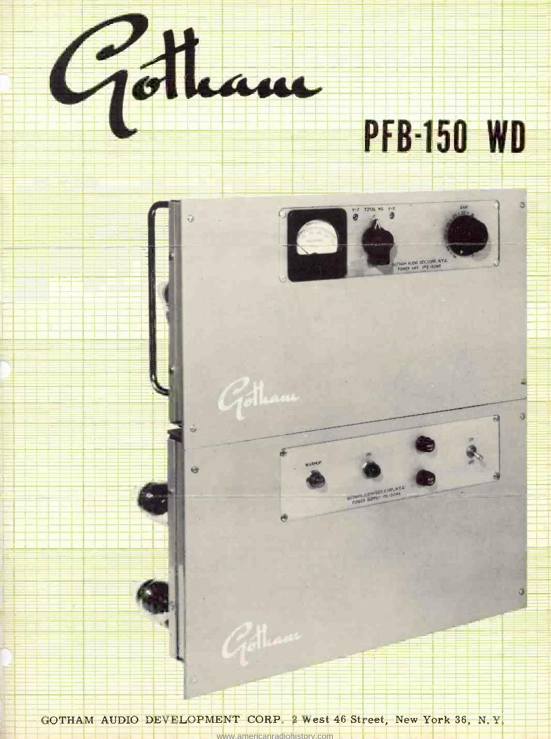
7
MINIM
PFB-150 WD
1-- C Emsrmumm. T swm.m. ammo - --
i w 11) p': ̀
)
GOTHAM AUDIO DEVELOPMENT CORP. 2 West 46 Street, New York 36, N. Y. www.americanradiohistory.com
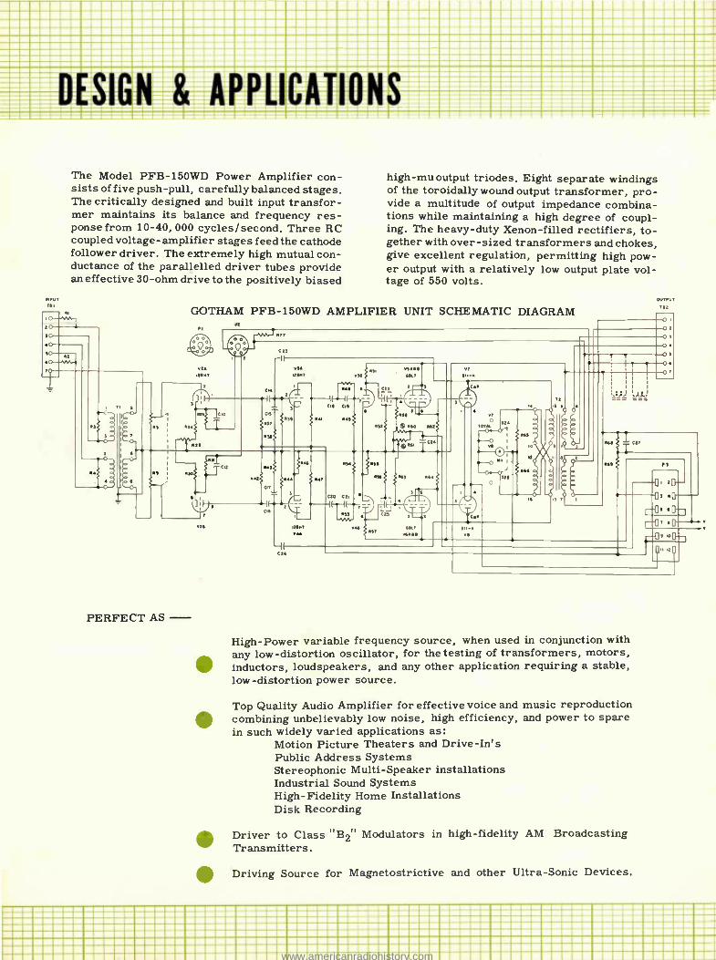
DESIGN & APPLICATIONS --MIMIMIMI
MIM::IN:IM:::::::: 11111111111111:_ :: =============== Z ==C ===== C =MINIMUM
The Model PFB -150WD Power Amplifier con- sists of five push -pull, carefully balanced stages. The critically designed and built input transfor- mer maintains its balance and frequency res- ponse from 10 -40, 000 cycles /second. Three RC coupled voltage - amplifier stages feed the cathode follower driver. The extremely high mutual con- ductance of the parallelled driver tubes provide an effective 30 -ohm drive to the positively biased
R11
high -mu output triodes. Eight separate windings of the toroidally wound output transformer, pro- vide a multitude of output impedance combina- tions while maintaining a high degree of coupl- ing. The heavy -duty Xenon -filled rectifiers, to- gether with over -sized transformers and chokes, give excellent regulation, permitting high pow- er output with a relatively low output plate vol- tage of 550 volts.
GOTHAM PFB -150WD AMPLIFIER UNIT SCHEMATIC DIAGRAM
PERFECT AS -
1
a, D
Ci.
High -Power variable frequency source, when used in conjunction with any low- distortion oscillator, for the testing of transformers, motors, inductors, loudspeakers, and any other application requiring a stable, low- distortion power source.
Top Quality Audio Amplifier for effective voice and music reproduction combining unbelievably low noise, high efficiency, and power to spare in such widely varied applications as:
Motion Picture Theaters and Drive -In's Public Address Systems Stereophonic Multi- Speaker installations Industrial Sound Systems High - Fidelity Home Installations Disk Recording
Driver to Class "B2" Modulators in high -fidelity AM Broadcasting Transmitters.
Driving Source for Magnetostrictive and other Ultra -Sonic Devices.
,---a, .
f--
_____°___i =MINIM i íriii0i MEE ..................NI...a... ...................... ...MI........
...NI.....NI.......NI.....NI... .............NI....NINI.íiNINI.MIMI..... NI NIMINI.MININIMIMINI.NI.MIMINIMI.NIMIMIMIMIMI.NI C.MIMIMIMIMI.NIMIMIMIMIMI..NIMIMIMIMIMIMIMIMINI.MIMIMIMIMIMIC.MIMI NI
MI.NIMIMIMIMIMI.NIMIMIMIMINIMIMIMIMIMIMIMIMIMIMIMIMI MIMIMIMIMINI.MIMIMIMI...MIMIMIMIMIMIMI...MIMIMI.MIMI....MIMIMI.MIMI .......... MEN MUM MEN MUM ....M www.americanradiohistory.com
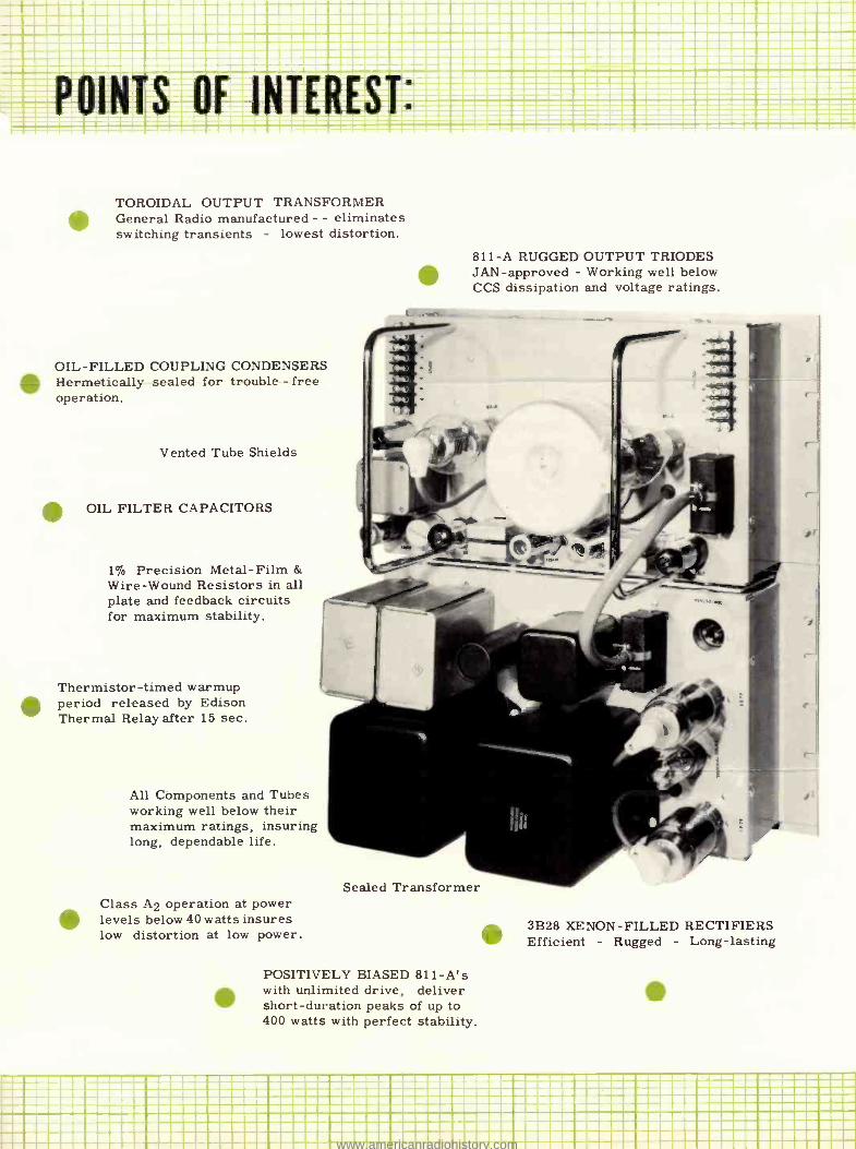
aaa .oaa _ a - aaaaaaaaaaaaaaaaamaa ________ .-...--..--..... aaa '----a-a°aaaa ' ---- ------ -- _- -------- - ,.r.----...=a
O =aCaaáaa- w'a-_ai 5= á POINTS OF INTEREST:
TOROIDAL OUTPUT TRANSFORMER General Radio manufactured - - eliminates switching transients - lowest distortion.
OIL -FILLED COUPLING CONDENSERS Hermetically sealed for trouble - free operation.
Vented Tube Shields
OIL FILTER CAPACITORS
1% Precision Metal -Film &
Wire -Wound Resistors in all plate and feedback circuits for maximum stability.
Thermistor -timed warmup period released by Edison Thermal Relay after 15 sec.
All Components and Tubes working well below their maximum ratings, insuring long, dependable life.
Class A2 operation at power levels below 40 watts insures low distortion at low power.
811 -A RUGGED OUTPUT TRIODES JAN- approved - Working well below CCS dissipation and voltage ratings.
Sealed Transformer
POSITIVELY BIASED 811 -A's with unlimited drive, deliver short -duration peaks of up to 400 watts with perfect stability.
3B28 XENON- FILLED RECTIFIERS Efficient - Rugged - Long - lasting
..... . MINCE
...... =a ............................................................. .... ... .............................................................. :aaaaaaaaaaaaaaaaaaaaaaaaaaaaaaaaaaaaaaaa::aaaaaaaaaaaaaaaaaaaaaaaaa .. MEN MM. ..MEIN .... MOM MIME ... MEN ..
www.americanradiohistory.com
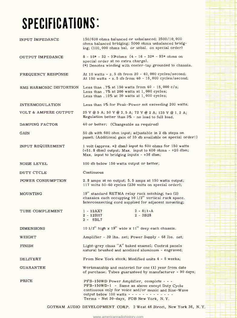
SPECIFICATIONS: INPUT IMPEDANCE
OUTPUT IMPEDANCE
FREQUENCY RESPONSE
RMS HARMONIC DISTORTION
INTERMODULATION
VOLT & AMPERE OUTPUT
DAMPING FACTOR
GAIN
INPUT REQUIREMENT
NOISE LEVEL
DUTY CYCLE
POWER CONSUMPTION
MOUNTING
TUBE COMPLEMENT
DIMENSIONS
WEIGHT
FINISH
DELIVERY
GUARANTEE
PRICE
150/600 ohms balanced or unbalanced; 2500/10, 000 ohms balanced bridging; 5000 ohms unbalanced bridg- ing; (100, 000 ohms bal, or unbal. on special order)
8 - 16* - 32 - 93ohms (4 - 16 - 32* - 93* ohms on special order at no extra charge). ( *) Denotes winding with center -tap grounded to chassis.
At 10 watts - ±. 5 db from 20 - 40, 000 cycles /second; At 150 watts - ±. 5 db from 40 - 15, 000 cycles /second;
Less than . 7% at 150 watts from 40 - 15, 000 c /s; Less than . 7% at 200 watts at 1, 000 cycles; Less than . 15% at 20 watts at 1, 000 cycles;
Less than 1% for Peak -Power not exceeding 200 watts;
25V @ 5 A ; 50 V @2.5A; 72 V @ 2 A ; 125V @ 1.2 A; Regulation better than 3% - no load to full load.
40 or better; (Changeable as required)
50 db with 600 ohm input; adjustable in 2 db steps on panel; (Additional gain of 35 db available on special order!)
1 volt (approx. +2 dbm) input to 600 ohms for 150 watts (+51.8 dbm) output; Max. input to 600 ohms - +20 dbm; Max. input to bridging inputs - +36 dbm;
100 db below 150 watts output or better;
Continuous
2.8 amps at no output; 5. 5 amps at 150 watts output; 117 volts 50 -60 cycles (230 volts on special order);
19" standard RETMA relay rack notching; two (2) chassies each occupying 10 1/2" vertical rack space. Interconnecting cord supplied for adjacent mounting;
1 - 12AX7 2 - 12BH7 2 - 6BL7
2 - 811 -A 2 - 3B28
10 1/2" high x 19" wide x 11" deep each chassis.
Amplifier - 39 lbs. net; Power Supply - 68 lbs. net;
Light -grey class "A" baked enamel; Control panels natural brushed and anodized aluminum - engraved;
From New York stock; Modified units 4 - 6 weeks;
Workmanship and materiel for one (1) year from date of purchase; Tubes guaranteed by manufacturer - 90 days;
PFB -150WD Power Amplifier, complete - - - PFB-150WD-1 - Same as above except Duty Cycle continuous only for voice and /or music and Sine -Wave output below 100 watts Terms - Net 30 -days, FOB New York, N. Y.
GOTHAM AUDIO DEVELOPMENT CORP. 2 West 46 Street, New York 36, N. Y.
www.americanradiohistory.com
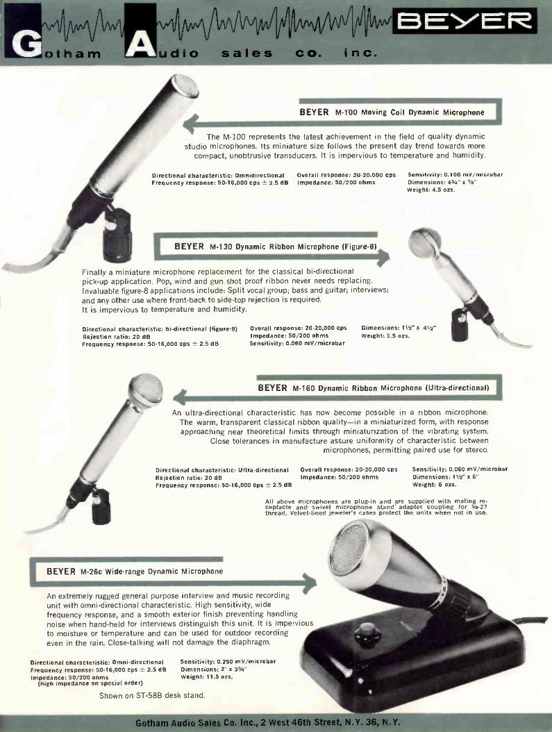
Al/i/Nmq, AN"
otham dio sales co. inc. BEYER
BEYER M -100 Moving Coil Dynamic Microphone
The M -100 represents the latest achievement in the field of quality dynamic studio microphones. Its miniature size follows the present day trend towards more
compact, unobtrusive transducers. It is impervious to temperature and humidity.
Directional characteristic: Omnidirectional Overall response: 20- 20.000 cps Sensitivity: 0.100 mV /microbar Frequency response: 50- 16,000 cps ± 2.5 dB Impedance: 50/200 ohms Dimensions: 4s/á' x s/e"
Weight: 4.5 ozs.
BEYER M -130 Dynamic Ribbon Microphone (Figure -8)
Finally a miniature microphone replacement for the classical bi- directional pick -up application. Pop, wind and gun shot proof ribbon never needs replacing. Invaluable figure -8 applications include: Split vocal group; bass and guitar; interviews; and any other use where front -back to side -top rejection is required. It is impervious to temperature and humidity.
Directional characteristic: bi- directional (figure -8) Overall response: 20-20,000 cps Dimensions: 11/z" x 41/2"
Rejection ratio: 20 dB Impedance: 50/200 ohms Weight: 5.5 ozs. Frequency response: 50. 16,000 cps - 2.5 dB Sensitivity: 0.080 mV /microbar
BEYER M -160 Dynamic Ribbon Microphone (Ultra -directional)
An ultra -directional characteristic has now become possible in a ribbon microphone. The warm, transparent classical ribbon quality -in a miniaturized form, with response approaching near theoretical limits through miniaturization of the vibrating system.
Close tolerances in manufacture assure uniformity of characteristic between microphones, permitting paired use for stereo.
Directional characteristic: Ultra- directional Overall response: 20- 20,000 cps Sensitivity: 0.060 mV /microbar Rejection ratio: 20 dB Impedance: 50/200 ohms Dimensions: 11h" x 6"
Weight: 6 ozs. Frequency response: 50- 16,000 cps ± 2.5 dB
All above microphones are plug -in and are supplied with mating re- ceptacle and swivel microphone stand' adapter coupling for 3b -27 thread. Velvet -lined jeweler's cases protect the units when not in use
BEYER M -26c Wide -range Dynamic Microphone
An extremely rugged general purpose interview and music recording unit with omni -directional characteristic. High sensitivity, wide frequency response, and a smooth exterior finish preventing handling noise when hand -held for interviews distinguish this unit. It is impervious to moisture or temperature and can be used for outdoor recording even in the rain. Close- talking will not damage the diaphragm.
Directional characteristic: Omni -directional Frequency response: 50. 16,000 cps ± 2.5 dB Impedance: 50/200 ohms
(high impedance on special order)
Shown on ST -588 desk stand.
Sensitivity: 0.250 mV /microbar Dimensions: 2" x 33/4"
Weight: 11.5 ozs.
Gotham Audio Sales Co. Inc., 2 West 46th StreriltrIWY. www.americanradiohistory.com
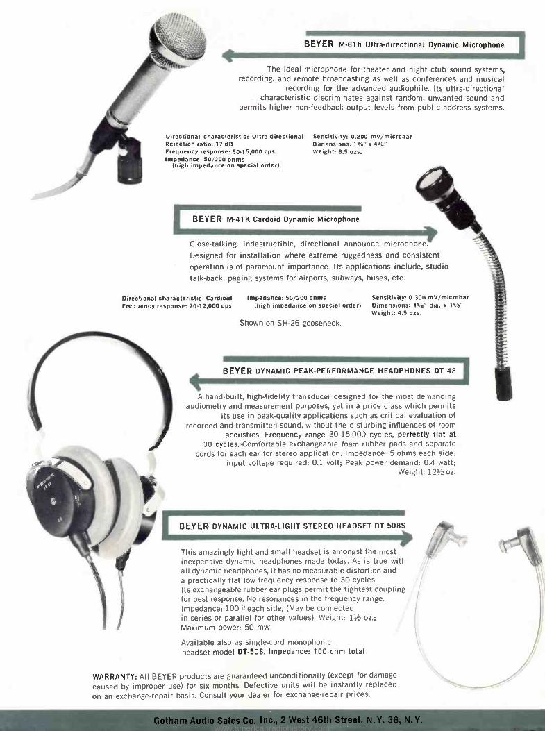
BEYER M -61b Ultra- directional Dynamic Microphone 1
The ideal microphone for theater and night club sound systems, recording, and remote broadcasting as well as conferences and musical
recording for the advanced audiophile. Its ultra -directional characteristic discriminates against random, unwanted sound and
permits higher non -feedback output levels from public address systems.
Directional characteristic: Ultra- directional Sensitivity: 0.200 mV /microbar Rejection ratio: 17 dB Dimensions: 1Y4' x 43/4' Frequency response: 50-15,000 cps Weight: 6.5 ozs. Impedance: 50/200 ohms
(high impedance on special order)
1 BEYER M -41K Cardoid Dynamic Microphone
Close- talking. indestructible, directional announce microphone.
Designed for installation where extreme ruggedness and consistent operation is of paramount importance. Its applications include, studio
talk -back; paging systems for airports, subways, buses, etc.
Directional characteristic: Cardioid Impedance: 50/200 ohms Frequency response: 70- 12,000 cps (high impedance on special order)
Shown on SH -26 gooseneck.
Sensitivity: 0.300 mV /microbar Dimensions: 15/e" dia. x 1s/a" Weight: 4.5 ozs.
BEYER DYNAMIC PEAK -PERFORMANCE HEADPHONES DT 48
A hand -built, high -fidelity transducer designed for the most demanding audiometry and measurement purposes, yet in a price class which permits
its use in peak -quality applications such as critical evaluation of recorded and transmitted sound, without the disturbing influences of room
acoustics. Frequency range 30- 15,000 cycles, perfectly flat at 30 cycles.'Comfortable exchangeable foam rubber pads and separate
cords for each ear for stereo application. Impedance: 5 ohms each side: input voltage required: 0.1 volt; Peak power demand: 0.4 watt;
Weight: 121/2 oz.
BEYER DYNAMIC ULTRA -LIGHT STEREO HEADSET DT 508S
This amazingly light and small headset is amongst the most inexpensive dynamic headphones made today. As is true with all dynamic headphones, it has no measurable distortion and a practically flat low frequency response to 30 cycles. Its exchangeable rubber ear plugs permit the tightest coupling for best response. No resonances in the frequency range. Impedance: 100 !leach side; (May be connected in series or parallel for other values). Weight: 11/2 oz.; Maximum power: 50 mW.
Available also as single -cord monophonic headset model DT -508. Impedance: 100 ohm total
WARRANTY: All BEYER products are guaranteed unconditionally (except for damage
caused by improper use) for six months. Defective units will be instantly replaced
on an exchange- repair basis. Consult your dealer for exchange- repair prices.
www.americanradiohistory.com
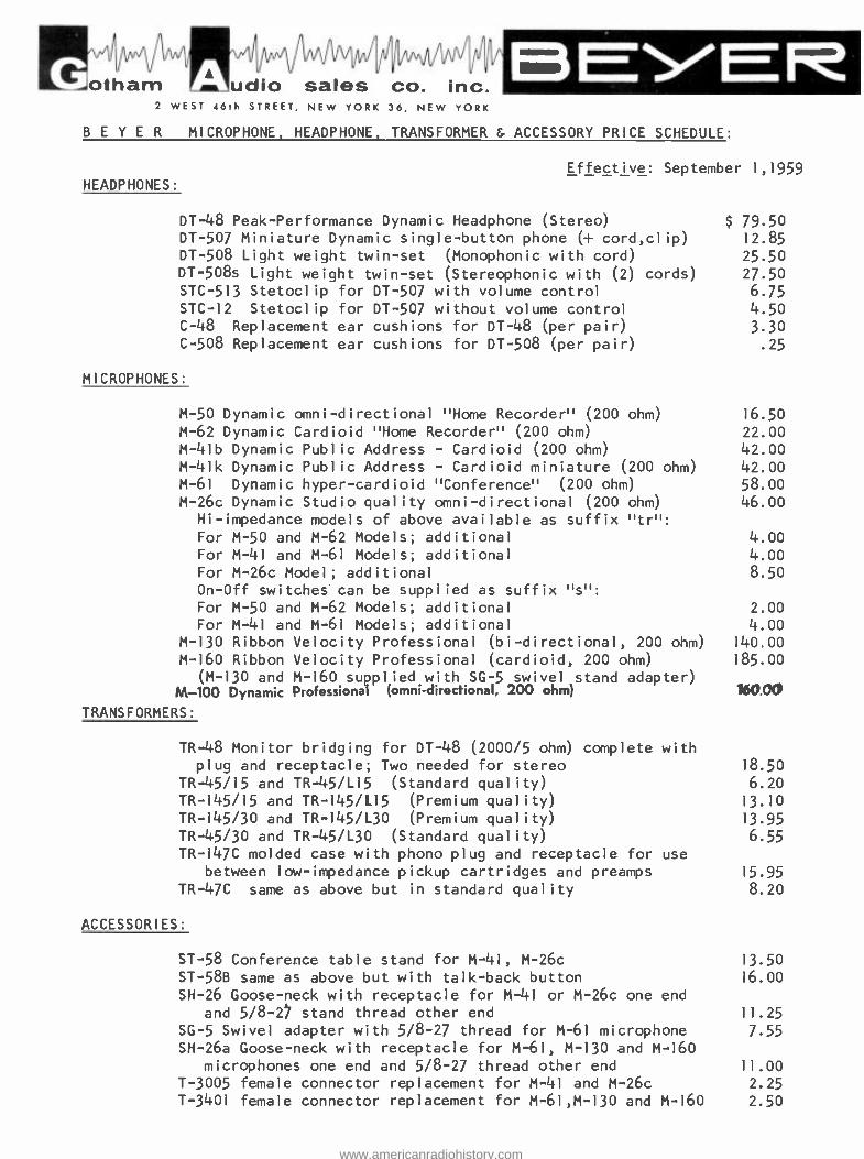
fri/lAmodpi, otham /`ludio sales co. inc.
2 WEST 46th STREET, NEW YORK 36, NEW YORK
B E Y E R MICROPHONE, HEADPHONE, TRANSFORMER & ACCESSORY PRICE SCHEDULE:
Effective: September 1,1959 HEADPHONES:
DT -48 Peak -Performance Dynamic Headphone (Stereo) DT -507 Miniature Dynamic single- button phone (+ cord,clip) DT -508 Light weight twin -set (Monophonic with cord) DT -508s Light weight twin -set (Stereophonic with (2) cords) STC -513 Stetoclip for DT -507 with volume control STC -12 Stetoclip for DT -507 without volume control C -48 Replacement ear cushions for DT -48 (per pair)
C -508 Replacement ear cushions for DT -508 (per pair)
MICROPHONES:
M -50 Dynamic omni -directional "Home Recorder" (200 ohm)
M -62 Dynamic Cardioid "Home Recorder" (200 ohm)
M -41b Dynamic Public Address - Cardioid (200 ohm)
M -41k Dynamic Public Address - Cardioid miniature (200 ohm) M -61 Dynamic hyper -cardioid "Conference" (200 ohm) M -26c Dynamic Studio quality omni- directional (200 ohm)
Hi- impedance models of above available as suffix "tr ": For M -50 and M -62 Models; additional For M -41 and M -61 Models; additional For M -26c Model; additional On -Off switches can be supplied as suffix "s ": For M -50 and M -62 Models; additional For M -41 and M -61 Models; additional
M -130 Ribbon Velocity Professional (bi- directional, 200 ohm)
M -160 Ribbon Velocity Professional (cardioid, 200 ohm)
(M -130 and M -160 supplied with SG -5 swivel stand adapter) M -100 Dynamic Professional (omen- directional, 200 ohm)
TRANSFORMERS:
TR -48 Monitor bridging for DT -48 (2000/5 ohm) complete with plug and receptacle; Two needed for stereo
TR -45/15 and TR- 45/L15 (Standard quality) TR- 145/15 and TR- 145/L15 (Premium quality) TR- 145/30 and TR- 145/L30 (Premium quality) TR -45/30 and TR- 45/L30 (Standard quality) TR -147C molded case with phono plug and receptacle for use
between low- impedance pickup cartridges and preamps TR -47C same as above but in standard quality
ACCESSORIES:
ST -58 Conference table stand for M -41, M -26c ST -58B same as above but with talk -back button SH -26 Goose -neck with receptacle for M -41 or M -26c one end
and 5/8 -27 stand thread other end SG -5 Swivel adapter with 5/8 -27 thread for M -61 microphone SH -26a Goose -neck with receptacle for M -61, M -130 and M -160
microphones one end and 5/8 -27 thread other end T -3005 female connector replacement for M -41 and M -26c T -3401 female connector replacement for M -61,M -130 and M -160
$ 79.50 12.85
25.50 27.50
6.75 4.50
3.30 .25
16.50
22.00 42.00 42.00 58.00
46.00
4.00 4.00 8.5o
2.00 4.00
140.00
185.00
160.00
18.50
6.20 13.10
13.95
6.55
15.95
8.20
13.50
16.00
11.25
7.55
11.00 2.25
2.50
www.americanradiohistory.com
PRICE R DUC ED TO:
1/4 "x2400'1 hub 1/2" x 2400' NAB hub
$ 14.50 list 29.00 list
AGFA ULTRA LOW -NOISE COBALT RECORDING TAPE
The AGFA Company, whose well known trade mark appears above, has just announced the release in the United States of its ultra low -noise recording
tape TYPE PE -22 - a tape which has been more than 5 years in the making.
This tape which has already swept the entire professional european recording field since its introduction in the spring of 1959, combines all
of the desirable physical properties with the latest revolutionary discover- ies in the magnetic particle field. The fundamentally new approach to the mag- netic coating is the use of COBALT in the iron oxide mixture, and the reduction
of the individual particle size to somewhere between one -fifth and one -tenth the diameter of current world production. The AGFA type PE -22 COBALT tape gives an actual net signal -to -noise improvement of about 7 dB - a figure
which has been verified by a number of users both here and abroad.
The mechanical properties are imparted to the tape by the use of
Mylar*, which has been pretensiled to a point where it actually equals the
strength of certain types of steel in these dimensions. The data below indi-
cates the results of the full test program of AGFA. Demonstration sample reels will be supplied upon request to interested parties in the professional field.
The PE -22 coating is available on 1 mil Mylar* (pretensiled) in widths
of 1/4" and 1/2" from New York stock in 2400 foot lengths on standard NAB hub.
Other lengths as well as special widths such as 16 mm, 17.5 mm and 35 mm will
be supplied on order.
MoJ tham fill/fAmoml
dio sales co. inc. 2 west 46th street new york 36, new york COlumbus 5 -4111 cable: telaudio newyork
www.americanradiohistory.com
AGFA High- Remanence COBALT Tape TYae PE -22:
Mechanical Specifications:
Thickness of backing (Mylar *): 25 micron (1 mil)
Thickness of coating: 25 micron (1 mil)
Elastic deformation coefficient: < 1% (2.2 lbs after 1 minute of loading or unloading @ 20 °C. -65% hum)
Plastic deformation coefficient: < 0.1% Breaking point loading: 28 kg /mm2 (14190 lbs /sq. in.)
Magnetic Specifications:
Coercivity: 285 Oersted Remanent saturating flux density: 1420 millimaxwell
Electroacoustic Specifications:
Flux density at standard reference level: 200 millimaxwell Flux density at peak recording level: 620 millimaxwell
Peak recording level in dB above reference: +9.8 dB (for 3% 3rd harm. dist.
at 15 ips and 5% and 7.5 ips)
Absolute sensitivity at 10KC referred to
1KC measured at -20 dB below reference: + 2.5 dB Total harm. dist. of 1KC at reference level: 0.28%
Print -through level after 24 hours at 1KC: > - 52 dB
Erase attenuation after 24 hours at 1KC: > 68 dB
Bias current for maximum output: 12.5 ma
NOTE: AGFA Type PE -22 tape is in every way compatible with all presently marketed domestic tapes, either acetate or Mylar* base, and can be
used on all machines without any realignment of equipment.
PRICES: AGFA Type PE -22 Mylar* base tape:
1/4" wide 2400 ft. on NAB hub $ 17.00 each LIST
1/2" wide 2400 ft. on NAB hub 34.00 each LIST
Discounts to bulk users available on application. Prices and specifi- cations subject to change without prior notice. E. & O.E.
;; Mylar - reg.T.M. DuPont
www.americanradiohistory.com
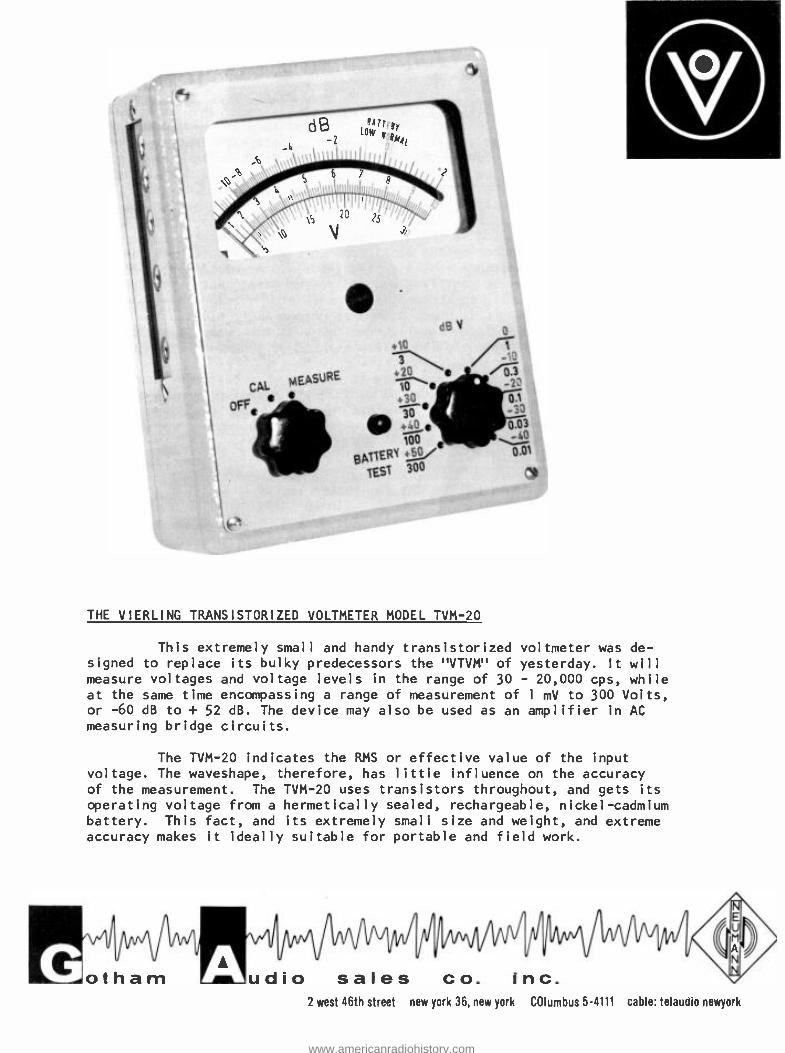
CAL MEASURE
oFFe
dß V
3 .20 _y
.3 / 0., 1 _;a o ._ 0.03
100 -i0
BpTTERY .5 0.0,
TEST 300
THE VIERLING TRANSISTORIZED VOLTMETER MODEL TVM -20
This extremely small and handy transistorized voltmeter was de- signed to replace its bulky predecessors the "VTVM" of yesterday. It will measure voltages and voltage levels in the range of 30 - 20,000 cps, while at the same time encompassing a range of measurement of 1 mV to 300 Volts, or -60 dB to + 52 dB. The device may also be used as an amplifier in AC measuring bridge circuits.
The TVM -20 indicates the RMS or effective value of the input voltage. The waveshape, therefore, has little influence on the accuracy of the measurement. The TVM -20 uses transistors throughout, and gets its
operating voltage from a hermetically sealed, rechargeable, nickel -cadmium battery. This fact, and its extremely small size and weight, and extreme accuracy makes it ideally suitable for portable and field work.
jyI
otham /AAllf
dio sales co. inc. 2 west 46th street new york 36, new york COlumbus 5 -4111 cable: telaudio newyork
www.americanradiohistory.com
FUNCTION AND CONSTRUCTION:
The TVM -20 consists of a three -stage, stabilized transistor ampli- fier with three pnp surface transistors. A feedback loop around two of those stages provides high stability and a sufficiently high input impedance for the amplifier. For purposes of calibration this feedback loop is con- trollable over a limited range. The amplifier is fully temperature compen- sated. . . .For re- calibration and alignment a test oscillator, using a
further pnp surface transistor is built into the unit. The output voltage of this 5000 cps oscillator is divided by means of a precision tapped transformer into two voltages, the quotient of which is equal to the re-
quired amplification factor of the amplifier. In the "Calibrate" position the smaller of these voltages is fed to the input of the amplifier. The higher voltage is likewise rectified and fed to the meter, but directly and with opposite polarity to the amplified oscillator voltage. By means of the feedback control it is now possible to change the amplification factor of the system until the total current through the meter is equal to
zero. The unit is thus aligned. The absolute level of the oscillator is
immaterial in this calibrating method. The TVM -20 is immediately ready to operate when switched on. Both
balanced and unbalanced voltages may be measured. The amplifier output is
brought out to earphone jacks and therefore the TVM -20 may be used as a
listening amplifier or the signal fed to an oscilloscope.
TECHNICAL DATA:
Frequency range: 30 - 20,000 cps Measurement range: In 10 steps of 10 dB each from
-40 dB to +50 dB (IOmV - 300 Volts) Smallest readable level (voltage): - 60 dB (1 mV)
Measurement error at 20 °C.(68 °F.): referred to full deflection:
Temperature coefficient of the
indication referred to full
deflection 0 °C. - 40 °C.:
Frequency response of indication over the range:
Measurement error for non sine - wave voltages:
Input resistance -
I. In ranges from -40 dB - 0 dB
(10 mV - 1 V): > 250,000 ohms -- 60 mmfd 2. In ranges from 0 dB - +50 dB
(3 V - 300 V): approx. 1.25 megohm -- 30 mmfd Greatest amplification factor in
most sensitive switch pos.: approx. 35 dB
Minimum earphone impedance: > 2000 ohms Average battery voltage: 6.25 volts Minimum useable battery voltage: 5.5 volts
Capacity of battery: 100 maH Current drain: "Calibrate ": approx. 2 ma
"Measure ": approx. 1.5 ma
Battery life in "Measure" pos.: > 72 hours Size: 3 13/16" x 5" x 2 1/2"
Weight: 28 ozs.
NET PRICE: $ 245.00
± 0.2 dB ( ±2 %)
<± 0.3 dB ( ±3 %)
<± 0.2 dB ( ±2 %)
< 0.5 dB ( 5 %)
www.americanradiohistory.com
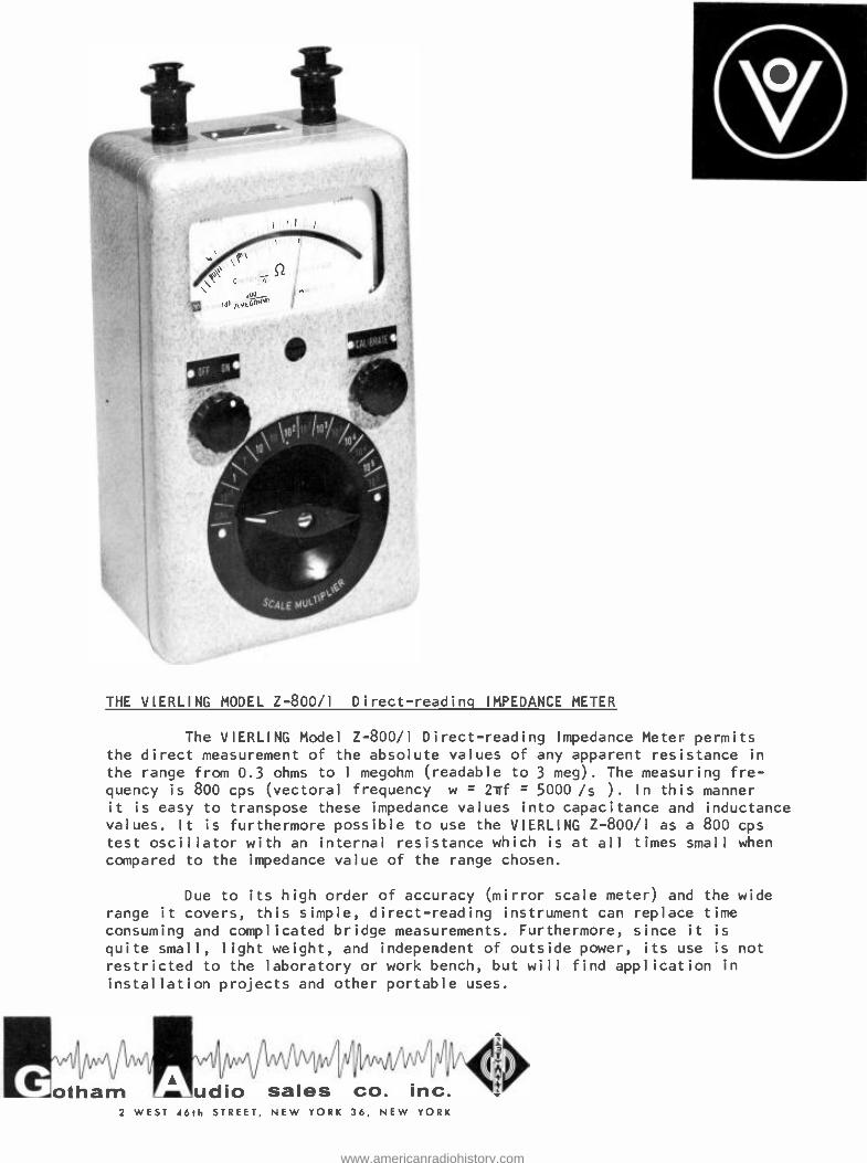
THE VIERLING MODEL Z -800/1 Direct -readinq IMPEDANCE METER
The VIERLING Model Z -800/1 Direct- reading Impedance Meter permits the direct measurement of the absolute values of any apparent resistance in
the range from 0.3 ohms to 1 megohm (readable to 3 meg). The measuring fre- quency is 800 cps (vectoral frequency w c 2irf = 5000 /s ). In this manner it is easy to transpose these impedance values into capacitance and inductance values. It is furthermore possible to use the VIERLING Z -800/1 as a 800 cps test oscillator with an internal resistance which is at all times small when compared to the impedance value of the range chosen.
Due to its high order of accuracy (mirror scale meter) and the wide range it covers, this simple, direct -reading instrument can replace time
consuming and complicated bridge measurements. Furthermore, since it is
quite small, light weight, and independent of outside power, its use is not
restricted to the laboratory or work bench, but will find application in
installation projects and other portable uses.
otham udio sales co. inc. 2 WEST 46th STREET, NEW YORK 36, NEW YORK
www.americanradiohistory.com
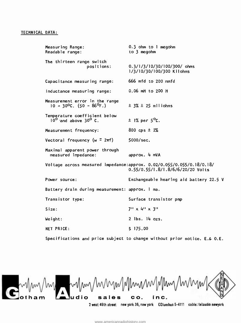
TECHNICAL DATA:
Mot1
ham
Measuring Range:
Readable range:
The thirteen range switch positions:
Capacitance measuring range:
Inductance measuring range:
Measurement error in the range 10 - 30 °C. (50 - 86 °F.)
Temperature coefficient below 10° .and above 30° C.
Measurement frequency:
Vectoral frequency (w = 2irf)
Maximal apparent power through measured impedance:
0.3 ohm to 1 megohm to 3 megohm
0.3/1/3/10/30/100 /300/ ohms 1/3/10/30/100/300 Kilohms
666 mfd to 200 mmfd
0.06 mH to 200 H
± 3% ± 25 miliohms
± 1% per 5 °C.
800 cps ± 2%
5000 /sec.
approx. 4 mVA
Voltage across measured impedance:approx. 0.02/0.055/0.055 /0.18/0.18/ 0.55/0.55/1.8/1.8 /6/6/20/20 Volts
Power source: Exchangeable hearing aid battery 22.5 V
Battery drain during measurement: approx. 1 ma.
Transistor type:
Size:
Weight:
NET PRICE:
Surface transistor pnp
7" x 4" x 3"
2 lbs. 14 ozs.
$ 175.00
Specifications and price subject to change without prior notice. E.& 0.E.
frilimodg dio sales co. inc.
2 west 46th street new york 36, new york COlumbus 5 -4111 cable: telaudio newyork
www.americanradiohistory.com
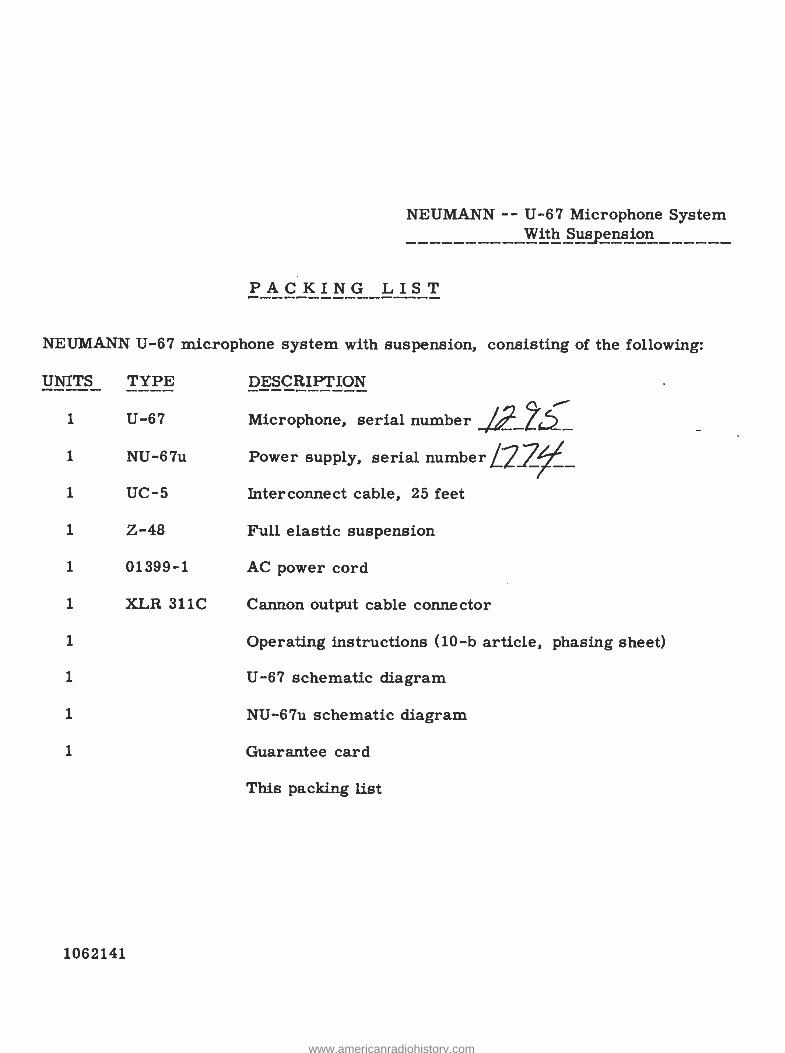
NEUMANN -- U -67 Microphone System With Suspension
PACKING LIST
NEUMANN U -67 microphone system with suspension, consisting of the following:
UNITS TYPE DESCRIPTION
1 U -67 Microphone, serial number
1 NU -67u
1 UC -5 Interconnect cable, 25 feet
1 Z -48 Full elastic suspension
1 01399 -1 AC power cord
1 XLR 311C Cannon output cable connector
1 Operating instructions (10 -b article, phasing sheet)
1 U -67 schematic diagram
1 NU -67u schematic diagram
1 Guarantee card
This packing list
Power supply, serial number L27_
1062141
www.americanradiohistory.com