Embed Size (px)
Citation preview

ectroricErujineennti
IIIIIMEoiiisOWAfifsi6ELECTRONICS. TELEVISION AND SHORT WAVE WORLD
PRINCIPAL
CONTENTS
Dielectric Strength of Ceramics.
Synchronisation of Oscillators.
The Encephalophone.
Data Sheet-R.C. Coupled Amplifiers.
MAR.,I943
PDF compression, OCR, web optimization using a watermarked evaluation copy of CVISION PDFCompressor

Electronic Engineering March, 1943
is now used for practically all radio coresbeing manufactured in this country. It is an,all -British Product, the result of extensiveresearch and development work carriedout during the last 15 years.
The use of a finely divided alloy of highmagnetic quality represents a furtheradvance in the science of Magnetic Powdermetallurgy in comparison with all thevarious grades of iron powder, most ofwhich previously have been imported.
MAIN ADVANTAGESO Higher permeability.CO Higher particle specific resistance.el Lower eddy current loss.O Non -rusting.
PEEL WORKS, SALFORD, 3. Telephones BLAckfriars 6688 (6 lines). Telegrams and Cables : "Sparkless, Manchester"
PROPRIETORS: THE GENERAL ELECTRIC Co. Ltd., OF ENGLAND
The fact that goods made of raw materials in short supply owing to war conditions are advertised inthis magazine should not be taken as an indication that they are necessarily available for export.
PDF compression, OCR, web optimization using a watermarked evaluation copy of CVISION PDFCompressor

March, 1943 Electronic Engineering 401
A
A Standard of Zero Loss AngleVARIABLE AIR CONDENSER TYPE D -1 4-A
This three -terminal double -screened condenser is provided with a guardcircuit which ensures that the dielectric of the plate -to -plate capacitance iscomposed entirely of air. This, together with the special surface treatmentof the plates redtices the plate -to -plate power loss to a quantity whichcan be disregarded even when measuring the smallest power factors.
BRIEF SPECIFICATIONCArACITANCE. 50 µµF min. 1,250 µMF max.
LOSS ANGLE. Approximately 1 micro -radian in a dryatmosphere : 7 micro -radians in 75% relative humidity,for the frequency range 50 c.p.s. to 10,000 c.p.s.
DRIVE. Worm reduction gear, 50: 1 ratio.
SCALE READING. To 1 part in 5,000 direct reading ;To 1 part in 20,000 by interpolation.
BACKLASH. Not exceeding 1 part in 20,000.
DIMENSIONS. 12. 71" x 10" x 13 5,'8".Write for Bulletin B -537-A giving further particulars.
MUIRHEADMUIRHEAD & COMPANY LTD., ELMERS END, BECKENHAM, KENT. TEL: BECKENHAM 0041-2.
FOR OVER 60 YEARS DESIGNERS AND MAKERS OF PRECISION INSTRUMENTS
C.R.C. 45
PDF compression, OCR, web optimization using a watermarked evaluation copy of CVISION PDFCompressor

402 Electronic Engineering March, 1943
;Availablein YCITi005
des cod ell thicfinessesin both fabric
and
?superliase,
IDELi110ZI
varyirtc:11aPproved
by the Admiralty,
try of SulapilGod the
.,ir i.fiittistri.fullest
details,samples
arid pricesas i-:11
os a co,p^:of our oev.
81.11.0.11fi,
'101be
sod on request.
11
" DELARON" is also supplied in panels cut and machined to your requirements. Ask too, for details of " HAMOFIL "Connecting Wires and Insulating Sleevings in all types ; and our NEW process-the printing of wiring diagrams, instructions,
etc., on " DELARON."
5, Regent Parade, Brighton Road, Sutton, Surrey. Telephone: Vigilant 4472
PDF compression, OCR, web optimization using a watermarked evaluation copy of CVISION PDFCompressor

March, 1943 403Electronic Engineering
Made in ThreePrincipal Materials
FREQUELEX-An Insulatingmaterial of Low Dielectric Loss.For Coil formers, Aerial Insulators,Valve Holders, etc.
PERMALEX-A High Permit-tivity Material. For the constructionof Condensers of the smallest possibledimensions.
TEMPLEX -A Condensermaterial of medium permittivity. Forthe constructionof Condensers havinga constant capacity at all temperatures.
"EverythingO.K. Sir !"
DIELECTRIC Loss problems in HighFrequency circuits have been solved by the use ofBullers Radio -Frequency Ceramics.
Many years of research and development in ourLaboratories have brought these materials to a highdegree of efficiency.
They are in constant use for transmission andreception and play an important part in maintainingcommunication under all conditions.
BullersLOW LOSS CERAMICS
BULLERS, LTD., THE HALL, OATLANDS DRIVE, WEYBRIDGE, SURREYTelephone : Walton -on -Thames 2451. Manchester Office : 196, Deansgate, Manchester
PDF compression, OCR, web optimization using a watermarked evaluation copy of CVISION PDFCompressor

Electronic Engineering March, 1943
COMMUNICATIONS, DEPEND....
Announcement
We manufacture Low Loss
Ceramic Parts at least asgood as any on the market
but we regret that we areat present unable to accept
orders for these as our pro-
duciion of these materials
is already being used forwork of national importance
6 sb: st,\4
by
6
, 7
,h sh,k! h
CHead Office : Eastwood, Hanley,Staffs. London : 85, StreathamHill, S.117.2. Factories at Han-ley, Stone and Longton, Staffs.Telephone: Twice Hill 5255-6
and Stoke-on-Trent 5272-4.
TAB/Tr/44
BULGINFOR
FUSESThe finest Radio and small Elec-trical Glass -enclosed Fuses in
the world. The comprehensiverange, from 60 MA. to 25 A.,covers every requirement.Accurate and uniform incharacteristics and made to BritishStandard Specification No. 646,R M.A.- , and R.C.M.F.-Specifi-cation. Absolutely fireproof andsafe, sure in action upon 50-75%overload.
ON SMALLPARTS....
In countless instances quiteintricate pieces of apparatusare wholly dependent on theproved reputation and relia-
bility of their component parts.
All products from the Houseof Bulgin are pre-eminent forsuperior design and workman-ship, and every article bearingour Trade Mark has to passexacting and exhaustive testsduring the course of its
production.
We ask the kind indulgenceof the public on delivery until
peaceful conditions return.
ALWAYS DEPEND ON
BULCINREGIST,ERED TRADE MARK
A. F. BULGIN X, CO. LTD., BY-PASS RD., BARKING, ESSEXTel. Rippleway 3474 (4 lines)
PDF compression, OCR, web optimization using a watermarked evaluation copy of CVISION PDFCompressor

Electronic Engineering 405March, 1943
QUALITATIVE EXAMINATIONOF SPECTRA.
The composition of materials used inthe manufacture of
Westinghouse Metal Rectifiersis determined by examination of aspectrogram on which are photographi.cally recorded the spectrum lines due tothe elements contained in the sampleIn many cases impurities of the order
of 0.00005% are detectable.
With nearly all our output earmarked,we regret that Westinghouse Rectifiersare so difficult to obtain. But behindthe ever increasing demands, technicians
work ceaselessly after new developments. After the warthere will be available to industry Westinghouse Rectifiersof remarkably advanced design-born of the persistant
research now going on.
WESTINGHOUSE BRAKE & SIGNAL CO. LTD.,PEW HILL HOUSE, CHIPPENHAM, WILTS
RECEIVERS
TRANSMITTERS
POWER PACKSfor priority con/rods only
PENTRANSFORMER CO.
Thornley Street, Wolverhampton Tel: Wolverhampton 22829
ElectronicEngineering
MARCH, 1943
Volume XV. No. 181.
CONTENTSPAGE
Editorial ... 407
Dielectric Strength of Porcelain and OtherCeramic Materials 408
The Synchronisation of Oscillators ... 412
A Single Sweep Time Base ... 418
The Encephalophone 419
Data Sheets 45 and 46 Performance of R.C.Coupled Amplifiers .. 421
Experimental Demonstrations for RadioTraining Classes 426
Standard Values of Resistors .. 430
A Circular Aerial for U.H.F. 432
A New Industrial X -Ray Unit 433
Straight Line Rotating Plate Condensers 434
March Meetings 435
Notes from the Industry 436
Abstracts of Electronic Literature 438
Patents Record 440
CONDITIONS OF SALE --This periodical is sold subject to thefollowing conditions, namely, that it shall not without thewritten consent of the publishers first given, be lent, re -sold,hired out or otherwise disposed of by way of Trade except at thefull retail price of 2/- and that it shall not be lent, re -sold, hiredout or otherwise disposed of in a mutilated condition or in anyunauthorised cover by way of Trade, or affixed to or as part ofany publication or advertising, literary or pictorial matter
whatsoever.
PDF compression, OCR, web optimization using a watermarked evaluation copy of CVISION PDFCompressor

406 Electronic Engineering March, 1943
THE EDISON SWAN ELECTRIC CO. LTD. 155, CHARING CROSS RD., LONDON, W.C.2
For full particulars write to Technical Service Department
PDF compression, OCR, web optimization using a watermarked evaluation copy of CVISION PDFCompressor
March, 1943 Electronic Engineering 407
PROPRIETORS a
HULTON PRESS LTD.,
ran
ectronicEngineering
EDITOR
G. PARR
EDITORIAL, ADVERTISING AND PUBLISHING OFFICES, 43-44, SHOE LANE, LONDON, E.C.4
TELEPHONE:
CENTRAL 7400
Monthly (published last day of preced-ing month) 2/- net. Subscription Rates :Post Paid to any part of the World -3 months, 6/6; 6 months, 13/- ; 12
months, 26/-. Registered for Trans-mission by Canadian Magazine Post.
TELEGRAMS:
HULTONPRES LUDLONDON.
TWO official glossaries of elec-trical terms and definitionshave recently appeared, the
one published by the AmericanInstitute of Electrical Engineers*and the other by the British Stan-dards institution f (Part r only).
While it is obviously unfair todraw any comparison between thepublications-the American one pro-duced without restriction on sizeand content, and the British onelimited by war conditions-it is per-missibk; to compare the definitionsas drawn up by engineers on bothsides of the Ntlantic.
What is the object of a glossary?It is obviously not intended to takethe place of a technical dictionary,but to crystallise the meaning of cer-tain technical terms which areliable to confusion or to regu-larise others which have creptinto the language.' It is not al-ways necessary to explain a termin order to define it, and acting onthis dictum, the B.S.I. glossary hasconfined itself to as few words aspossible and deals only with essen-tial terms. This lays the Glossaryopen to the usual criticism that whatis non -essential to some readers isof importance to others. For exam-ple, it is assumed that Ohm's Law
American Standard Definitions of ElectricalTerms (The American Institute of Electrical Engineers,
tr.s.A.) ;1.25.t Glossary of Terms used In Electrical Engineering
(Section 1), (The British Standards Institution),BS.206, Part 1. 21- net.
Glossariesis so familiar that it is not foundamong the fundamental electric andmagnetic terms. But the Americanglossary has it between Lenz andJoule, with a rider that it does notapply to all circuits.
In the fundamental units theAmerican glossary gives three orfour pages of explanatory defini-tions, an example which could wellbe followed. These may be foundin any text -book, but it is conveni-ent to have a master reference bookwhich will set them out clearly inrelation to one another. As a men-tal exercise, readers might definethe following without reference to abook :
Abtmpere, Gilbert, Maxwell,
ELECTRONIC ENGINEERINGMONOGRAPHS.
Owing to the demand for copies of thefirst Monograph on
FREQUENCY MODULATION "by K. R. Sturley
the initial printing order was exhaustedwithin a few weeks of issue.
The publishers have now been able toreprint a further number of copies whichcan be obtained through the usualchannels, or, in cases of difficulty, fromthis office. The price is 2s. 6d. net.
Will readers who have been disap-pointed in obtaining copies please writeto the Circulation Dept., Hulton Press,43, Shoe Lane, E.C.4.
A remittance for 2s. 8d. to includepostage should accompany the order.
Newton, and if these are too easy,try Phot and Apostilb.
It is not possible to draw a fullcomparison in the electrical defini-tions as the B.S.I. Glossary is pub-lished in separate parts. The one ofmost interest to radio engineers(Terms relating to Telecommunica-tion) which comprised sections 9and to of the 1936 edition is beingpublished separately under B.S.204, 5943.
It is, however, embarrassing tofind that the British electron isactually fatter than its Americancounterpart, even under war -timeconditions. Here are the figures :American definition:
An electron is the natural elemen-tary qualify of negative electricity.
The quantity of electricity on anelectron is 1.592 x so-" coulomb,or 4.774 x lo -1° electrostatic unit.
The mass of the electron at restis 9.00 x 50-28 gm.British definition:
An elementary particle cqntain-ing the smallest negative electriccharge (4.803 x ro--" E.S. unit)and having a mass of 9.11 xto' gm. at low velocities.
In these days of brains trusts andquizzes the B.S.I. Glossary is a use-ful book to carry round where scien-tists gather. It is pretty sure tostart an argument and it has thegreat advantage that the topics arenot on the secret list.
PDF compression, OCR, web optimization using a watermarked evaluation copy of CVISION PDFCompressor

408 Electronic Engineering March, 1943
Dielectric or Puncture Strength of Porcelainand Other Ceramic Materials
THE dielectric or breakdownstrength of an insulating mate-rial is that property which deter-
mines its suitability for use as a hightension insulator. The dielectricstrength may be defined as the voltagegradient at which the electrical break-down occurs. The dielectric strengthof porcelain and other ceramic in-sulating materials-as well as that ofall other solid insulating materials --is, to a very high degree, dependentupon the test conditions. It is cal-culated by dividing the breakdownvoltage by the thickness of the testspecimen between the electrodes antis commonly expressed in volts permil or kilovolts per millimetre (I voltper mil corresponds approximately to25 kV per millimetre).
The test values for dielectricstrength of an insulating materialvary to an extent not generally appre-ciated with :-
(1) The thickness of material.(2) The duration and rate of in-
crease of the voltage applied.(3) The characteristics of the volt-
age applied (frequency andwave shape).
(4) Electrostatic field distribution(edge effects, surroundingmedia).
(5) Temperature of the material.In order to obtain comparable
values for the breakdown character-istics of the dielectric, the conditionsenumerated above must be exactlythe same for the material tested.
Tests on specimens of differentthicknesses, tests made with differentelectrodes, tests made with differentrates of voltage increase, or in dif-ferent surrounding media, are notcomparable.
The test methods for ascertainingthe dielectric strength of electrical in-sulating materials at power. fre-quencies are, therefore, standardisedin various countries. In the UnitedStates, for instance, there are Speci-fications designated D. 149/40 T. andD. 116 (Standard Methods of TestingElectrical Porcelain) and in GermanyV.D.E. 0303/1929. But since wallthickness, rate of increase of voltageand the nature of electrodes are notthe same, the values obtained in ac-cordance with the A.S.T.M. Methodsand the V.D.E. Methods are not com-parable-the V.D.E. Method givingmuch higher Test Values.
The main difference between the
By Dr. Ing. E. ROSENTHAL
a
b
)
Fig I. Test Specimens. (a) with the electrodesformed by metal coatings provided on thesurface of two spherical cavities. (b) with onemetal coated cavity and a metal disk with
rounded edges.
American and V.D.E. Methods is asfollows :-The American TentativeMethods specify (for porcelain)electrodes having the shape of ametal disk 0.75 in. diameter, withedges rounded to a radius of On.Plain, unrecessed, test pieces of uni-form thickness are used. The V.D.E.recommends electrodes formed bymetal coatings deposited on both sur-faces of a recessed test disk. The testdisk has, therefore, not a uniformthickness since one or two hemis-pherical cavities are inserted in thecentre of one or both of the faces ofthe disk, the smallest wall thicknessof the porcelain between the two metalcoatings being 2 mm. (Fig. I). Onthe other hand, the American TestStandards for electrical porcelainprovide for a thickness of a test speci-men being 0.250 in. (6.35 mm.), 0.4 in.(10.16 mm.), 0.75 in. (19.05 mm.) orI in. (2.54 mm.).
The breakdown in the case of theGerman test specimen.. generallyoccurs across the shortest distance be-tiveen the two hemispherical metalcoatings inserted into the disk. Fieldconcentrations which may occur in airor under oil around the peripheraledges of the two metal coatings haveno influence on the breakdownstrength because the porcelain thick-ness between these two edges is somuch greater than the shortest dis-tance between the two hemisphericalelectrodes that breakdown betweenthese electrodes occurs before anyedge effects can influence the dielectric properties of the test specimen.
In the case of test arrangements, asspecified by the A.S.T.M. Methods,edge effects under oil develop betweenthe rounded edges of the electrodeand the test specimen, resulting inpremature breakdown' of the specimen.Relation of Breakdown Strength to
Thickness of MaterialFig. 2 illustrates, the breakdown
voltage of porcelain disks of varyingthicknesses in different surroundingmedia, and illustrates the consider-
able influence which the surroundingmedia have on the breakdown voltageowing to edge effects caused by sur-rounding media having higher break-down strength and lower dielectricconstant than porcelain.
The same Fig. (Curve 1) shows thebreakdown voltage of porcelain disksof varying thicknesses when edgeeffects are eliminated, that is to say,the actual breakdown strength ofporcelain.
Curve 2 shows the breakdownstrength of porcelain disks of variousthicknesses in transformer oil of bestinsulating quality. Curve 3 shows thesame plates in used transformer oil,and Curve 4 the same plates in lowresistance oil.
In explanation of the considerabledecrease in dielectric strength permil, with increasing thickness ofsolid materials, many theories havebeen advanced. In the early days thisphenomenon was explained by the as-sumption that it is much more diffi-cult to produce thick-walled porcelaindisks than thin -walled ones, and thatthe decreasing puncture strength istherefore caused by the lower qualityof thicker specimens. This explana-tion is, however, unsatisfactory be-cause the decrease in puncturestrength can be ascertained withalmost any kind of solid insulatingmaterial and even with those wherethick-walled articles are easier tomanufacture than thin ones. Further-more, thin slices cut out of an insula-tor disk have often a higher puncturestrength per mil than that of theoriginal complete disk.
Within the last few years physicistshave made prpnounced progress in thestudy of the dielectric failure, but inspite of this progress our knowledgeof the phenomena involved is stillvery incomplete so far as solid insu-lating materials are concerned.
In order to form an idea. as to whythe dielectric strength of solid insulat-ing materials decreases with increas-ing thickness, it may be as well to dis-cuss at this stage the theory of break-down.Theory of Breakdown
Dielectric failure of solid insulat-ing materials may occur in one of thefollowing ways, or in a combinationof both :-
(a) In disruptive breakdown; and(b) In thermal breakdown.
PDF compression, OCR, web optimization using a watermarked evaluation copy of CVISION PDFCompressor

March, 1943 Electronic Engineering 409
500
kV.
400
300
200
00
0 10 20Thickness in mm
2
30
Fig. 2. Breakdown voltage of porcelain disks. (I With no edge effects (Wagner and We cker).(2) Plates in transformer oil (pure). (3) Plates in transformer oil (used). (4) Plates n low
resistance oil.
Disruptive failure is one which re-sults directly from an electrical over-stress of the dielectric material with-out perceptible internal temperaturerise. It is caused by ionisation andcollision within the molecular struc-ture of the material.
Disruptive failure only occurs in thecase of solid insulating materialsunder special conditions, and accuratetest values of pure disruptive dielec-tric strength for such materials arenot easily obtained. If tests are madeon very thin specimens so that heatmay easily be dissipated by the elec-trodes and a sufficiently high voltageis applied to cause instantaneousbreakdown, that there is no time forheat to develop in the thin section,the failure is purely disruptive. Im-pulse tests on thin ceramic sectionscause a breakdown which is pre-dominantly, or almost purely disrup-tive. With increasing thickness inter-nal temperature effects modify thecharacteristics of disruptive failure.The breakdown strength per unit wallthickness at first decreases slowlywith increasing wall thickness andthen more rapidly when a certain wallthickness is reached, the breakdownshowing more and more the character-istics of thermal breakdown with in-creasing wall thickness. Heat de-veloped under the influence of thealternating electric field between theelectrodes can less easily be dissipatedwhen the wall thickness increases.When a certain thickness of thespecimen is reached, a further increase in wall thickness will then nolonger result in an increase of break-down voltage. The curves (Fig. z)show that this critical wall thickness,the increase of which would not causea further increase in breakdown volt-age, depends not only on the dielecztric properties of the test specimen,
B
but also on the nature of the surround-ing medium. Theoretically, thedisruptive breakdown voltage isproportional to the thickness ofthe test specimen* The curves showthat for commercial frequencies andfor thicknesses such as are used inactual insulation design, disruptivebreakdown is the smaller and thermalbreakdown the larger of the two com-ponents causing the actual breakdown.Disruptive breakdown strength is thehigher the more homogeneous thestructure of the insulating materials.Thermal breakdown strength is deter-mined :
(i) By electrical conductivity(volume resistance).
(2) By thermal conductivity.(3) Power factor.(4) Dielectric constant of the
sulating material (specificductive capacity, or per-mitivity).
The higher the dielectric constantand the higher the power factor of thetest specimen, the higher will be theelectrical losses and more heat will bedeveloped. The heat developed de-creases the volume resistance of thematerial and more current will de-velop further heat until breakdownoccurs.
It is well known that every insulatorcoming within the influence of an elec-tric alternating field consumes a cer-tain amount of electric energy andtransforms it into heat. The electricalenergy lost in this way is given nearlyenough by the following equation :-
N = V227fC tan 8V is the voltagef the frequencyC the capacity
specimentan 8 the tangent of the loss
angle, or the power factorof the insulating material.
where
in-in -
of the test
It can be concluded from thisformula that insulating materials hav-ing a higher power factor possess alower dielectric breakdown strength,particularly at high frequencies andif the voltage is applied for a longperiod, or increased at a small rate,i.e., if the thermal component of theactual breakdown is predominant.The disruptive breakdown, however,seems to be less dependent on thepower factor.
The curves illustrating the depend-ence of temperature on the breakdownstrength of various ceramic materialsshow the influence of the power factoron the thermal breakdown strength.(Fig. 5).
Although the phenomena causingbreakdown cannot be attributed ex-clusively to the two factors " disrup-tive " and " thermal " breakdown,there is no doubt that these are thetwo most important factors and thebreakdowns which occur in practiceare in most cases the result of thesetwo factors.
Short -time (or impulse) tests arepredominately disruptive in theirnature and long-time tests, high fre-quency tests and tests at elevated tem-peratures are predominately thermal.In most cases, disruptive and thermaleffects combine to produce failure. Ifthe breakdown is purely disruptivethe breakdown current increases froma substantial steady value to break-down in a fraction of a microsecond.
Electrostatic Field Distribution andEdge EffectsBoth in the actual application of
insulation and in the testing of it forbreakdown strength, it is not easy toavoid conditions which lead to localfield concentrations and similareffects which reduce the breakdownvoltage.* These are generally re-ferred to as " edge effects " becausethey are observed at the edges of elec-trodes, although field concentrationsare, of course, not limited to theedges of the electrodes. Unequalfield distribution, concentration of thefield, edge effects, etc., etc., have agreat influence on breakdown voltage.
E. B. Shand : Dielectric Strength of Glass.Electrical Engineering Transactions-August, x941.
.26
24
:122
120
IS40 80 1200 160
Temperature °C200
Fig. 3. The breakdown strength of porcelainwith temperature. (a) Impulse voltage. (b)Voltage increased at the rate of 250 v/sec.
(c) Voltage Increased at the rate of 25 v/sec.(Rosenthal-Mitteilungen 1926)
PDF compression, OCR, web optimization using a watermarked evaluation copy of CVISION PDFCompressor
410 Electronic Engineering March, 1943
100
kV.
80
8)60
ao
20
01
2 3 4Thickness in rrTn.
5
a
b
6
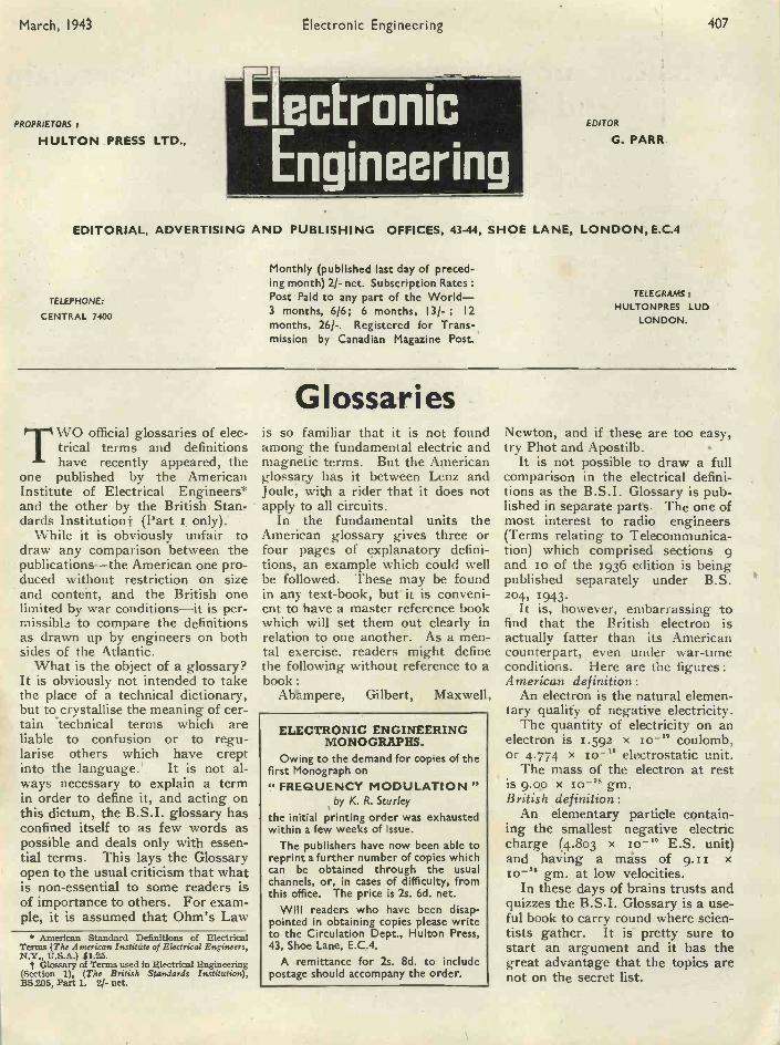
Fig. 4 Variation of breakdown voltage of Porcelain with wall thickness and rate of Increase ofvoltage. (a) Impulse voltage. (b) Voltage increased by 250 v/sec. (c) Voltage increased by
25 v/sec.
Even in elaborate tests it is not easyto eliminate electric field concentra-tions completely. Many discrepanciesin published data on the breakdownstrengths of solid materials resultfrom small differences in the test ar-rangements causing edge effects ofvarious strengths. In addition to theconcentrations at the edges of theelectrodes, these effects are producedby imperfect contact between the elec-trodes and the insulation, by scratchesin the electrode surface, when theelectrode is in the form of a thinmetal foil or metal coating, by in-cluded air -pockets or pores in the testspecimen, and by scratches and otherimperfections of the surface of thedielectric itself. A special type ofedge effect is that connected with theinfluence of the ambient medium onthe field distribution, such as insulat-ing oil.
Dielectric tests are frequently madeunder oil in order to eliminate flash-over of the test specimen. Insulatingoils have a dielectric constant muchlower than that of porcelain andglass so that the electrical stress inthe oil will be correspondingly higherthan in the material having the higherdielectric constant. Under these con-ditions, Corona discharges will formin the oil long before the breakdownvoltage of the test spqcimen is ap-proached. Streamers develop on thesurface of the test specimen, com-mencing on the edges of the electrode.The higher the resistance of the in-
(Rosenthal-Mitteilungen 1926)
sulating oil, the more concentratedare these discharges. These streamerscause intense voltage gradients alongthe surface of the insulation rapidlycausing disintegration. If this actioncontinues for a certain time a holemay be bored into the surface of thetest specimen causing dielectricfailure before the actual breakdownstrength of the test specimen has beenapproached. This type of failure isdependent on the dielectric resistanceof the oil, and, to a lesser degreeonly on the dielectric propertiesof the test specimen. (Fig. 2) showsthe influence of various oils on thepuncture strength of porcelain. Itcan be seen that the higher the dielec-tric strength of the surroundingmedium, the lower the breakdownstrength of the test specimen. Thesecurves show very clearly the great in-fluence which the dielectric propertiesof the surrounding medium have onthe dielectric properties of the testspecimen and that tests made in dif-ferent surrounding media are notcomparable.
Edge effects, also, play a very im-portant part in actual breakdownunder normal service conditions. Im-perfections between the electrode andthe insulator surface produce fieldconcentration which, very often islargely responsible for breakdown atvoltages far below the actual break-down voltage of the insulating mate-rial in question.
In the design of electrical insulators
and components like bushings, etc.,where metal parts have to be affixedto the porcelain insulator, these con-ditions have to be carefully con-sidered and field concentrationsavoided as far as possible. This .canbe achieved by suitable design of boththe electrodes and the insulator andby suitable assembly methods. Theapplication.of conductive and semi -conductive coatings on the surface ofthe insulator (particularly on curva-tures with generous radii and by con-necting the metal coatings with themetal work) has been used to an in-creasing extent during recent years inorder to improve field distribution.
In this connexion reference may bemade to the importance of the hardand non -attackable surface of porce-lain and porcelain glazes. Surfaceirregularities and scratches producedon the surfaces of the insulator bymetal parts during assembly, maycause edge effects which may beresponsible for early breakdown.Fortunately, both porcelain andporcelain glazes are so hard thatscratches caused by metal parts arepractically excluded. Any imperfec-tions of the surface (whether they bedue to scratches caused by a tool orby the live metal -work under serviceconditions, or whether they be cavitiesinvisible to the naked eye caused byatmospheric conditions and resultingin a matt surface) are bound to causeedge effects with the inherent detri-mental influence on breakdownstrength. Very few insulating mate-rials possess the same hardness andunattackability ' by chemical and
atmospheric influences as does porce-lain.Duration and Rate of Increase of
Applied VoltageFig. 4 shows the dependence of
breakdown voltage of porcelain onwall thickness and the rate of in-crease of voltage. It can be seen thatfor thin sections the influence of dif-ferent rates of voltage increase is verysmall. The influence of rate of volt-age increase becomes more pro-nounced with increasing wall thick-ness. The breakdown strength of testspecimens with great wall thickness islower when the voltage is slowly in-crealed, compared with breakdownstrength measured at more rapid ratesof voltage increase. In the case ofimpulse voltage, the breakdownstrength is higher than in the case oftests carried out at commercial fre-quencies-the more so the thicker thetest specimen. It can be seen, there-fore, that the rate of voltage increase,or in other words the time duringwhich the voltage is applied, is an im-portant factor in determining break-down voltage.
PDF compression, OCR, web optimization using a watermarked evaluation copy of CVISION PDFCompressor
March, 1943 Electronic Engineering 411
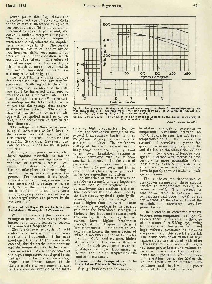
Curve (c) in this Fig. shows thebreakdown voltage of porcelain disksif the voltage is increased by 25 voltsper second ; curve (b) if the voltage isincreased by 25o volts per second, andcurve (a) under a steep wave impulse.The tests at commercial frequencywere made in oil, whereas the impulsetests were made in air. The resultsof impulse tests in oil and in air donot, however, differ very much if thetests are made under conditions whichexclude edge effects. The effect ofrate of increase of voltage on dielec-tric strength is more pronounced inthe case of bakelised laminated in-sulating material (Fig. 5a).
The A.S.T.M. Standards providefor short -time tests and for step-by-step tests. With fegard to the short -time tests, it is provided that the volt-age shall be increased from zero tobreakdown at a uniform rate. Therate of rise is o.5 or i.o kV per second,depending on the total test time re-quired and the voltage time charac-teristic of the material. The step-by-step test provides that an initial volt-age will be applied equal to 5o percent, of the breakdown voltage in theshort -time test.
The voltage will then be increasedin equal increments as laid down inthe various material specifications.For testing electrical porcelain theA.S.T.M. Standards, however, pro-vide no specifications for the step-by-step test.
With regard to porcelain and otherdense ceramic materials, it can bestated tliat it does not age under theinfluence of electrical stress. Testscarried out show that depreciationdoes not take place-at least during aperiod of many years at power fre-quency. For instance, if the break-down strength of a. test specimen hasbeen ascertained, a voltage of to percent, below the breakdown voltagecan be applied to it for. many yearsWithout causing breakdown (of courseif no irregularities are present in thetest specimen).
Effect of Voltage Characteristics onBreakdown Strength of Ceramics
With direct current the breakdownvoltage of 'porcelain is 20-3o per cent.higher than with alternating currentat commercial frequencies.
The breakdown strength of solidmaterials is lower at high frequenciesthan at low frequencies. It has beenmentioned that as the frequency is in-creased, the dielectric losses increaseand the temperature in the test speci-men increases. As a consequence ofthe high temperature developed in thetest specimen, the breakdown voltagedrops. The power factor of thedielectric plays a very important paiton the dielectric strength of the mate -
E 1.6
0.
-1 I 2
00
600
400E5,
200
1
2
0
MEIMIEN'U...IIMMIIIIIMEIIIMEMMEMMMEMI111111111111111111111111111MINELIIII
11111111111111111111MEMENNEMEN MEM
50 100 150 200Degrees Centigrade
3Time in minutes
250
Fig. 5. Upper curves. Variation of breakdown strength of three C inoenstatite materialsw'th temperature. (I) AlSiMag 196 (p.f. 0.14 per cent, at 60 c/s). (2) AlSiMag 35 (p.f. 0.30 percent. at c/s). (3) AlSiMag 192 (p.f. 0.20 per cent. at 60 c/s).Fig. Sa. Lower Curve. The effect of rate of increase in voltage on the dielectric strength of
black varnished cambric.(A.S.T.M. Standards, p.69).
rials at high frequencies. For in-stance, the breakdown strength of im-proved Clinoenstatite bodies is 35-45kV per mm. at 5o cycles, and 25-27 kVper mm. at i Mc/s. The breakdownvoltage of this special type of ceramicbody drops, therefore, only by about4o per cent. (breakdown voltage at
Mc/s. compared with that at com-mercial frequency). In the case ofporcelain the breakdown voltagedrops by 50-60 per cent. and in thecase of most glasses by 70 per cent.,under corresponding conditions.
The influence of wall thickness onbreakdown strength is more importantat high than at low frequencies. If,by employing thin sections and mas-sive electrodes the heat developed bythe high frequency field is quickly dis-sipated, the breakdown strength perunit is higher than otherwise. Thereare puzzling exceptions to the generalrule that the breakdown strength ishigher at low frequencies than at highfrequencies. Rutile bodies, for in-stance, have higher breakdownstrength at high frequencies than atlow frequencies. This refers to cer-tain rutile bodies, the power factor ofwhich is too times higher at 800 cyclesthan at x Mc/s., and 300 times higherat commercial frequencies than at
Mc/s. In such very special cases thebreakdown at low frequencies isthermal and at high frequencies dis-ruptive in. character.Influence of the Temperature of theMaterial on Dielectric Strength
Fig. 3 illustrates the dependence of
breakdown strength of porcelain ontemperature variations between 20-160° C. It can be seen that within thistemperature range the breakdownstrength of porcelain at power fre-quency decreases only very slightly,and the less so the slower the voltageincrease. In the case of impulse volt-age the decrease with increasing tem-perature is more noticeable. Fromthese curves it can be inferredthat ata temperature of 16o° C. the break-down is purely thermal under all volt-age conditions.
Fig. 5 shows the dependence ofbreakdown strength of three steatitearticles at temperatures varying be-tween 25-25o° C. The decrease inbreakdown strength between roomtemperature and about too° C. is notconsiderable in the case of two of thematerials both possessing a very lowpower factor.
The decrease in dielectric strengthbetween room temperature and 250° C.is only about 15 per cent. in the caseof the material AlSiMag 196, owingto the extremely low .power factor andhigh volume resistance at elevatedtemperatures of this special material.The same breakdown values at hightemperatures are attained with otherClinoenstatite type materials havingthe same power factor and volume re-sistance. Breakdown strength at tem-peratures higher than 8od C. is, gener-ally speaking, better the higher thevolume resistivity at elevated tem-peratures and the lower the powerfactor of the material under test.
PDF compression, OCR, web optimization using a watermarked evaluation copy of CVISION PDFCompressor
412 Electronic Engineering March, 1943
The Synchronisation of OscillatorsBy D. G. TUCKER, B.Sc. (Eng.), A.M.I.E.E.*
Part I.- The Direct Synchronisation of Feedback Oscillators
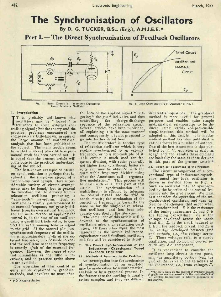
Pig. I. Basic Circuit of Inductance -CapacitanceTuned Feedback Oscillator. ,
I. IntroductionIT is probably well-known thatoscillators may be " locked " infrequency to some external con-
trolling signal ; but the theory and thepractical problems encountered arecomparatively little-known, in spite ofthe large amount of mathematicalanalysis that has been published onthe subject. The main trouble seemsto be that in recent years little experi-mental work has been carried out. Itis hoped that the present article willcontribute to the practical understand-ing of the subject.
The best-known example of oscillator synchronisation is perhaps that in-volved in the time -base circuit of acathode-ray oscillograph. Here a con-siderable variety of circuit arrange-ments may be found,' but in generalthe time -base will be derived from arelaxation oscillator producing a" saw -tooth " wave -form. Such anoscillator is readily synchroniseed toan external frequency not greatly dif-ferent from its own natural frequency,and the usual method of applying thecontrol is, in the case of an oscillatorusing a gas -filled triode valve, to con-nect the synchronising tone or signalto the grid. If the natural (i.e., un-synchronised) frequency of the oscillator is approximately 1/nth of the ex-ternal frequency, it is possible to con-trol the oscillator so that its frequencyis exactly i /nth of the external fre-quency. However, the range of con-trol diminishes as the ratio n in-creases, and in practice ratios aboveso are avoided.
The operation of this control isquite simply explained by graphicalmethods, and involves no more than
* P.O. Research Station
Fig. 2. Loop Characteristics of Oscillator of Fig. I.
the idea of the applied signal " trig-gering " the gas -filled valve and thuscontrolling the charge -dischargesequence pf the relaxation circuit.Several articles have been published,all explaining it in the same manner'and consequently it is not proposed togo into further detail here.
The multivibrator8 is another typeof relaxation oscillator which is veryreadily synchronised to an externalfrequency, or to a sub -multiple of it.This circuit is much used for fre-quency division, with ratios generallynot higher than 5, although better re-sults can now be obtained with thequasi -stable frequency divider' usingwhat the Americans call " regenera-tive modulation." This process willbe dealt with in a later part of thisarticle. The synchronisation of amultivibrator is effected by injectingthe control signal into the grid oranode circuit ; the mechanism of thecontrol of frequency is basically thesame as for the single -valve relaxa-tion oscillator, and has been ade-quately described in the literature.'
The remainder of this article will bedevoted to the synchronisation ofoscillators other than relaxation oscil-lators. Of these other types, the mostimportant is the simple inductance -capacitance tuned feedback oscillator,and this will be considered in detail.2. The Direct Synchronisation of the
Inductance - Capacitance TunedFeedback Oscillator
2.1. Methods of Approach to the ProblemAn investigation into the mechanism
of synchronisation of an oscillatormay be made either by a mathematicalanalysis or by a graphical process. Inthe former case the working is usuallyrather complex and involves difficult
differential equations. The graphicalmethod is more useful for generalpurposes and enables quite simplemathematical relationships to be. de-duced using readily comprehensiblesimplifications-this method will be
'adopted in this article. The mathe-matical method has been published invarious forms by a number of authors.One of the best treatments is that pub-lished by E. V. Appleton as early as1923," and the results there obtainedare basically the same as those derivedin this part of the present article.*
2.2. Graphical Treatment of the Problem.The circuit arrangement of a con-
ventional type of inductance -capacit-ance tuned feed -back oscillator isshown in skeleton form in Fig. i.Such an oscillator may be synchron-ised by the injection of the control fre-quency into the grid circuit. We mustfirst consider the operation of the un-synchronised oscillator, and then de-termine the changes that occur whenit is synchronised. R is the resistanceof the tuning inductance L, and C isthe tuning capacitaince. E. is thevoltage developed across the anodeload R.. E. is the e.m.f. induced inL from the feedback circuit, and Eg isthe voltage developed between gridand cathode, i.e., tile voltage acrossC. These voltages refer to a steadyoscillation, and do not, of course, in-clude any d.c. component.
It is convenient to consider theoscillator loop circuit in two parts,one, the amplifying portion from thegrid of the valve to the terminals ofthe inductance, i.e., from voltages Eg -
*The early work on the subject of synchronisationof oscillators was concerned with the mutual effect oftwo wireless transmitters in relative proximity toone another.
PDF compression, OCR, web optimization using a watermarked evaluation copy of CVISION PDFCompressor

March, 1943 Electronic Engineering 413
M
E.4
A
CURVE OF E, COS 0 V E.
/ CURVE, OF E,v E
(a)
E,_I
ESC
( b)
x
B
Fig. 3. Graphical Construction.Fig. 4. Typical Locking Characteristic ; 1 kc s
oscillator with Q = 15, and Eg = I volt.(From P.O.E.E.I.)
to E.; and the other, the tuned cir-cuit, i.e., from voltages E. to Eg.The first is non-linear in that theamplification of the valve decreases asthe applied voltage increases. Thesecond may be considered linear forthe present purpose, although in prac-tice, if the inductance is iron -cored,there is a slight non -linearity herealso.
Fig. 2 shows the voltage relationsof the loop circuit graphically. Ifoscillation is to take place, it isclearly essential that the two curvesshould intersect at some point (repre-senting the condition of stable oscilla-tion) remote from the origin; in otherwords, the resultant loss or gain roundthe loop must be zero in the steadystate. The greater the gain of thevalve at low voltages, the greater isthe voltage to which the oscillationwill build up, in order that the loopgain may be reduced to zero. Anotherfundamental requirement is that thephase shift round the loop shall bezero or a multiple of 360°. This canonly be adjusted by a slight changein frequency, which changes the phaserelation between Eg and E. in thetuned circuit. This requirement ex-plains why oscillators rarely oscillateat the natural frequency of the tunedcircuit. Evidently, it will be neces-sary to determine the frequency ofoscillation from this phase -shift re-quirement before the graph of Egagainst E. for the tuned circuit canbe plotted in Fig. 2. Having deter-mined the mode of oscillation of theunsynchronised oscillator, let us nextconsider the circuit relationships if asynchronising or " locking " signal,*E.y,, is injected into the grid circuit,as shown in Fig. i. If the naturalfrequency of the oscillator is 630/27r,then the phase difference go betweenE. and the current in the tuned cir-
Throughout the article the word "synchronising"and " locking " will be regarded as synonymous.
rO
O
!.14
lH
2
0 05 IO 15 20 25 30VOLTAGE OF LOCKING SIGNAL
35 4.0
cuit, when the oscillator is unsyn-chronised is given by tan 95. =(coL - pa.0 IR. But if the oscillatoris forced by the injected signal tooscillate at a different frequencyco.../27r, then the phase difference be-comes ', where tan 951
- I POsynC
RReferring now to Fig. 3, which
shows in (a) the loop gain character-istic, we can construct a vector dia-gram as shown in (b). AB is taken asthe direction of the vector represent-ing the voltage E. on the grid. Byforcing the oscillator to change itsfrequency, we have changed the phaseshift in the tuned circuit by an amount
= 951 - O. and consequently the volt-age Ec across the condenser differs inphase from Eg by an amount 95. Thedirection AC of the vector represent-ing E, can now be indicated in Fig.(3b).
It is convenient to arrange thatpoint A of the vector diagram is inline with OY, and to replot thestraight line graph to represent therelation between Ec cos q and E.. Letthe intersection of this line with thecurve be L. If any horizontal linethrough a point M on OY is drawn tocut the curve and straight line aboveL, and from the point of intersectionwith the straight line a perpendicularis dropped to the Ee vector line at P,and from the point of intersection withthe curve a perpendicular is droppedto the Eg vector line at Q, then com-plete vectors Ec = AP and Eg = AQare obtained corresponding to a cer-tain value of E,. It is evident that
to " lock " the oscillator stably inthis particular condition at this fre-quency co.,12qr, it is necessarey to adda synchronising vector E., PQ tocomplete the vector triangle.
If less synchronising voltage thanthat corresponding to PQ is injected,then the E. and E. vectors adjustthemselves to a smaller value, andOM becomes smaller. When thehorizontal line passes through L, thevector E., is vertical. This conditionrepresents the boundary of the syn-chronised range of operation; if E.,is reduced further, the oscillator willnot synchronise. The vertical condi-tion where synchronisation fails isgenerally referred tg as the " pull-out."
2.3. Conclusions from the above work J '
The vector diagram determinedabove (which was first published byU.Bab.6) does not, of course, explainhow " pull -in " and " pull-out "occur, but it does demonstrate clearlythe magnitudes and phase angles ob-tained in a synchronised oscillator.The following properties of the cir-cuit will be noted :-
(a) The greater the locking voltageE.y., the greater can be the angle g;and since g is a measure of the differ-ence between the natural frequency ofthe oscillator and the control fre-quency, it is clear that the greater isE.,. the greater is the frequency rangeover which synchronisation is pos-sible.
(b) Since the output of the oscilla-tor will normally be taken from acrossthe anode load, we can consider thephase of the output to be determined
PDF compression, OCR, web optimization using a watermarked evaluation copy of CVISION PDFCompressor
414 Electronic Engineering March, 1943
exactly by the phase of Eg. The phaseof Eg relative to E., is go° at pull-out. If E., remains constant, andthe frequency difference is reduced,then 55 is reduced, and the angle PQAbecomes acute. When the frequencydifference is zero, E.g. and E. are ex-actly in phase. As the frequency dif-ference is increased again in theopposite direction s becomes nega-tive, and the phase difference betweenEs and E. is now of opposite sign,reaching a limit of -go° at pull-out.
These two properties of the syn-chronised oscillator generally deter-mine the practical design of syn-chronised systems. It is useful toplot them for any particular oscillatoras
(a) a locking characteristic; {thisshows the difference between thenatural and control frequencies plot-ted against the voltage of control fre-quency required just to effect pull -in.A typical curve measured on a certaini kc/s. oscillator is shown in Fig. 4.
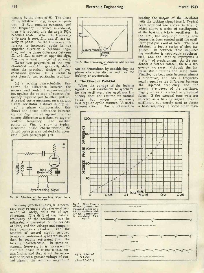
(b) a phase characteristic; thisshows the phase difference betweenEg and E, plotted against the fre-quency difference at a fixed voltage ofcontrol frequency. The markedpoints in Fig. 5 show a typicalmeasured phase characteristic ; thedotted curve is a calculated character-istic. (See paragraph 5.2).
Synchronising Signal
Fig. B. Injection of Synchronising Signal in a
Practical Case.
In many practical cases, it is neces-sary only to ensure that the oscillatornever, or rarely, pulls out of syn-chronism. The drift of the naturalfrequency of the oscillator can beestimated or measured for the periodsof time, and the voltage and tempera-ture conditions involved, and theamount of control signal requiredto ensure continuous synchronism canthen be readily estimated from thelocking characteristic. In some in-stances, however, it is necessary tomaintain phase relations within cer-tain limits, and then it will be neces-sary to inject a greater voltage of con-trol signal ; the required magnitude
Fig. 7. Beat Frequency of Oscillator with InjectedTone.
can be determined by considering thephase characteristic as well as thelocking characteristic.
3. The Effect of Pull -OutWhen the voltage of the locking
signal is just insufficient to synchron-ise the oscillator, the oscillator fre-quency does not assume io naturalvalue, but varies continuouslyin a regular cyclic manner. A usefuldemonstration of this is obtained by
beating the output of the oscillatorwith the locking signal itself. Typicalbeats obtained are shown in Fig. 6,which shows a series of oscillogramsof the beat of a 6 kc/s. oscillator. Inthe first, the oscillator tuning con-denser has been. rotated until the oscil-lator just pulls out of lock. The beatobtained is just a series of slow im-pulses. In between these impulsesthe oscillator is apparently synchron-ised, and the impulse represents a" slip " of synchronism. As the con-denser is further rotated, the beat fre-quency increases, although the im-pulse itself retains the same form.Finally, the beat note becomes almosta sine -wave, and has a frequencynearly equal to the difference betweenthe injected frequency and thenatural frequency of the oscillator.Fig. 7 shows this effect in graphicalform. If the external tone were notinjected as a locking signal into theoscillator, but merely used to obtaina beat -frequency in some other man -
100 UMMIIIIMME MU= MIIIIIIIIIIMINu, 1111111111M11111111111M MIN= MEE NM=(..) 111111MMIIIIIIIIIMIIIMEMF4111111111111z IIMIIIIIIMIIIIIIIIIIIIIIMIEWIIIIMINIMIllwcc8° INIIIIMMIIIIIMMINIMIIIIINEW MENUIt: MIEMINIIIIIMMIIIIMIMMEN111111111M1111111113 MIIMMIIIIIIIIMMIEMIMINEIMMIIIIE
60.................511...M.111..11111.11111.1111......115111111.M.tn
cti IIMMIIIIIIIIMIIIMIIIINIMMIIIIII11111111111110111=11111M111M211111111=11111111M1
4 01111=1=11111111111111MIPONIIIMIIIMINIEllcc' IMMINIIIIIIIIIMPIIIIIMIIIMEM111111110 1111111M1M11111111121111111MIIIME EWEN41121 IIIIMIIMINEMIIIIIIIIMIMMENMI= =IEEEEMMEN MMIMMIIIIIIIMIll
MENEM ENIIIIMMIIIIMIIIMMEMIIMINsmignomminimmiumunimaginummommornmoomEN........ EMI= INNIMIll100 '°-(0.05 O 1 4'00.15
20
0 2 0.25
Fig. 5. Phase Charac-teristic. Crosses aremeasured values on a6 kc/s oscillator withQ= 125. Dotted curveis calculated from
eqn. 3.
Fig. 6. Effect ofPull -Out.
(From P.O.E.E.1.)
PDF compression, OCR, web optimization using a watermarked evaluation copy of CVISION PDFCompressor

March, 1943 Electronic Engineering 415
ner, the curve of beat -note against ex-ternal frequency would be merely twostraight lines at 45° to the axes, asshown dotted. But when the externaltone is used as a controlling signal,the effect is as shown in full lines, andover the locking range, the beat -noteis, of course, zero. Some interestingmeasurements on this beat -note havebeen published by Subra.7
4. Method of Injection of Synchronis-ing Tone
Although in Fig. r the synchronis-ing voltage is shown injected directlybetween the tuned circuit and thegrid, this connexion would not gener-ally be desirable in practice. It isbetter to inject the voltage across aresistance connected between thetuned circuit and the H.T. negative,as shown in Fig. 8. The value of theresistance can be determined by thenature of the circuit supplying thesynchronising signal.
There are other methods of inject-ing the synchronising tone; one thatis sometimes convenient at high fre-quencies is to couple the synchronis-ing circuit to the tuning inductor bymeans of a loosely coupled coil.
0.1
.075
.05
.025
5. Simple Quantitative Relationshipsin Synchronised Feedback Oscil-lators
S.I. Dependence of the Locking -range Charac-teristics on the Circuit Parameters
Some very useful quantitative rela-tions may be deduced from the pre-ceding work. We have stated, 95. =(40E. - 030
where wa/zir is thenatural frequency, and tan 0i =<4.yaL - co.,,C
where way./zqr is theR
controlled frequency.Now the angle 0 of the vector dia-
gram (Fig. 4) is given by 0 = 01 - 0..If all these anglps are small, we mayassume that tan 0 = tan 0i - tan 00so that
cusy,IL - woL - cuoC
tan =R R
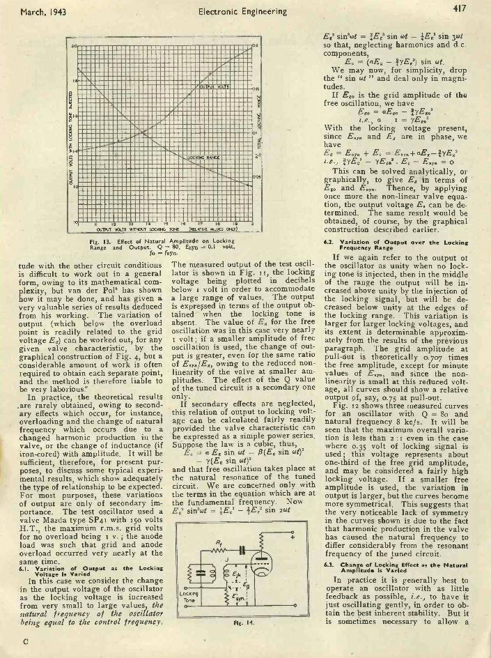
Fig. 9 ( right). Locking Characteristicof 4 kc/s Oscillator Q=50, Eg =0.5
volt.Fig. 10 (below). Locking Range in
Relation to Q. Eg = I volt.Fig. II. Increase in Output asLocking Tone Increased. Eg =
I volt.
000
02540
0520
.075 1 IA10 Q
6.7.,, - coo 1
- L +R coow.y.0 -I
It is usual to refer to the Q value of acoil rather than to its resistance ;therefore we can substitute IIR=Q/waLfor convenience. Also, if way. - wois small, we can replace t/woway.0 byi/wa2C, and since 0.0.2C = L verynearly, we obtain
Q(64,0 - 00)tan 45 = (2L). =
w0L
4(0.y.-63.)(1)
Wa
In the majority of practical casesthe voltage of synchronising signal re-quired just to lock the oscillator is theimportant value in the design of thesynchronising system; only wheregreat phase stability is required willany other value be a design factor. Atthe limit of the locking range, the
x
Q=80
Q .15
80 70 60 50 40 30 20 10LEVEL OF LOCKING TONE IN db. RELATIVE TO I v.
I3O
PDF compression, OCR, web optimization using a watermarked evaluation copy of CVISION PDFCompressor

416 Electronic Engineering
vector Egy is perpendicular to Eg; letthe limiting value of Esyn byThen
= tan 95
EgSo that we now have
co.y. - woEyna = 2Q Eg. ... (2)
Wp
Q is known, but it should not be for-gotten that allowance must be madefor the damping of Rf + R. on thetuned circuit. Eg is known or can bedetermined for any particular valveand loop gain characteristic. Thegrid voltage is not constant over thelocking range, and the value of Eg inequation (2) is strictly the value justbefore pull-out; but fortunately thisvalue is related to the amplitude offree oscillation independently ofEgy or Q or (to,- co.)/too-it is 0.707 xthe free amplitude for a cube lawvalve characteristic (see Appendix).Thus Eg above is somewhat less thanthe r.m.s. voltage required to causethe valve to run into grid current.Thus for a given oscillator circuitEgya.i cc (togyn - o) for small lockingranges. It is, in practice, found thatthe locking characteristic is a straightline for the usual small ranges, say0.1 per cent. on the frequency scale ofa normal LC oscillator, as may beseen in Fig. g.
Another important result to be ob-served from the equation above is thatfor a given locking voltage, but avariable Q, we obtain (co". - coo) cct/Q which means that the greater theQ (i.e., the lower the resistance of thecoil), the smaller is the range of fre-quency over which the oscillator canbe synchronised. Fig. so shows agraph of this relation actually
measured on a working oscillator, inwhich the tuned circuit could bedamped by a parallel resistance as re-quired. For every reading the loopgain was adjusted so that the circuitjust oscillated gently, and Eg waskept constant. The valve used wastype SP4i (Mazda). Egyn was kept at0.025 volts ; Eg was about i volt. Themeasured results agree reasonablyclosely with equation (i) for smalllocking ranges. The tests were car-ried out at about so kc/s, but the lock-ing range has been plotted as (weyn -0.).)1(oo x too, in order to express it in aconvenient form independent of theactual frequency.5.2. Derivation of the Equation to the Phase
CharacteristicReferring again to the vector dia-
gram of Fig. 3, it is seen that thephase angle between the lockingsignal and the resultant grid voltageis LPQA, which we may designate O.
Let to/27r be any synchronised fre-quency and w,12.77- be the frequency oflocking signal at which pull-outoccurs. The natural frequency of theoscillator is 64/27, as before.
From the vector triangle,Ellyn Eg
sin cb sin (0 + 95)since sin (cr - 0 - s6) = sin (9 + 0) sothat sin B cos + cos B sin cb
= (Eg sin cb)/E.y..Since 95 is small, sin 95 95 and cos'
thus sin B + 95 cos 0 = Eg561 EsynUsing equation (s) of the preceding
section, we obtainCO - CO.
sin B + cos 0.2Qwo
Eg w - wo0o-.2Q
E.,.
March, 1943
and equation (2) gives us (changingsymbols as necessary)
Eg wo
. 2Q -Es,. cuy - coo
E gy coo
2Q =Eg w, - w.
so that
and
Egy -w-w.sin 0 + cos 0
Eg 63, -63o - coand since Esyni Eg is generally small,and since as cos 0 increases
(w - wo)
(c,h - too)
decreases, we have finally (and ap-proximately)
sin - - CO°
(3)co, - too
So that the phase characteristic asdescribed earlier and illustrated inFig. 5 should be very nearly a sine -wave. That this is so in the case ofFig. 5 may be seen by comparing themeasured curve (marked with crosses)with the curve calculated from equa-tion (3) (shown in dotted lines). Theagreement is very close.
6. Considerations of Oscillator Out-put Amplitude
It was seen from the graphicalanalysis of Fig. 3 that the workingpoints on the loop characteristic curveswere altered by the addition of thesynchronising signal. This meansthat the output of the oscillator variesas the synchronising tone is varied,both in magnitude and frequency,relative to the free oscillation. Theexact law relating the output ampli-
1 5
.Gl4
9EC
123..,=0.
o 1.oo..,eu
..p,>
E 8
2
60.
8
Locking Voltage 035v..--.-----...,
01v.
0.032 v.,
0 100 200 300 400 500 600 700 800 900ARBITRARY FREQUENCY SCALE 900 divs . 75 04
Fig. 12. Variation in Output over the Locking Range. Q 80.
PDF compression, OCR, web optimization using a watermarked evaluation copy of CVISION PDFCompressor
March, 1943 Electronic Engineering 417
aTPUT VOLTS 0
0
RANGE
0ti
12 13 14 1'5 IS
OUTPUT %O -TS WITHOUT LOCKING TONE
FS 1.9 2
(RELAT WE VALUES ONLY)
Fig. 13. Effect of Natural Amplitude on LockingRange and Output. Q = 80, Esyq = 0.1 volt,
fo = fsyn
tude with the other circuit conditionsis difficult to work out in a generalform, owing to its mathematical com-plexity, but van der Pole has shownhow it may be done, and has given avery valuable series of results deducedfrom his working. The variation ofoutput (which below the overloadpoint is readily related to the gridvoltage E.) can be worked out, for anygiven valve characteristic, by thegraphical construction of Fig. 4, but aconsiderable amount of work is oftenrequired to obtain each separate point,and the method is therefore liable tobe very laborious.'
In practice, the theoretical results.are rarely obtained, owing to second-ary effects which occur, for instance,overloading and the change of naturalfrequency which occurs due to achanged harmonic production in thevalve, or the change of inductance (ifiron -cored) with amplitude. It will besufficient, therefore, for present pur-poses, to discuss some typical experi-mental results, which show adequatelythe type of relationship to be expected.For most purposes, these variationsof output are only of secondary im-portance. The test oscillator used avalve Mazda type SP41 with sso voltsH.T., the maximum r.m.s. grid voltsfor no overload being v.; the anodeload was such that grid and anodeoverload occurred very nearly at thesame time.6.1. Variation of Output as the Locking
Voltage is VariedIn this case we consider the change
in the output voltage of the oscillatoras the locking voltage is increasedfrom very small to large values, thenatural frequency of the oscillatorbeing equal to the control frequency.
C
The measured output of the test oscil-lator is shown in Fig. is, the lockingvoltage being plotted in decibelsbelow i volt in order to accommodatea large range of values. The outputis exprqsed in terms of the output ob-tained when the locking tone isabsent. The value of E. for the freeoscillation was in this case very nearly
volt; if a smaller amplitude of freeoscillation is used, the change of out-put is greater, even for the same ratioof owing to the reduced non -linearity of the valve at smaller am-plitudes. The effect of theof the tuned circuit is a secondary oneonly.
If secondary effects are neglected,this relation of output to locking volt-age can be calculated fairly readilyprovided the valve characteristic ,canbe expressed as a simple power series.Suppose the law is a cubic, thus,
E. = a Eg sin cot - 13(E, sin wt)'- 7(Eg sin (st)'
and that free oscillation takes place atthe natural resonance of the tunedcircuit. We are concerned only withthe terms in the equation which are atthe fundamental' frequency. Now
=: V2,2 - sin zwtsin'cut
Fig. 14.
E.' sinawt = PiEe sin cut - lEge sin yotso that, neglecting harmonics and d.c.components,
Ec = (aE. - 17E.8) sin wt.We may now, for simplicity, drop
the " sin tut " and deal only in magni-tudes.
If Ego is the grid amplitude of thefree oscillation, we have
Ego = aEi.e., a = yE'go2
With the locking voltage present,since E.1. and E. are in phase, wehaveEg = E. + E, = E...-FaE.-IyEgai.e., ,VEY3 - . E.- E.y. = o
This can be solved analytically, orgraphically, to give E. in terms ofE80 and E.,,.. Thence, by applying,once more the non-linear valve equa-tion, the output voltage E. can be de-termined. The same result would beobtained, of course, by the graphicalconstruction described earlier.6.2. Variation of Output over the Locking
Frequency Range
If we again refer to the output ofthe oscillator as unity when no lock-ing tone is injected, then in the middleof the range the output will be in-'creased above unity by the injection ofthe locking signal, but will be de-creased below unity at the edges ofthe locking range. This variation islarger for larger locking voltages, andits extent is determinable approxim-ately from the results of the previousparagraph. The grid amplitude atpull-out is theoretically 0.707 timesthe free amplitude, except for minutevalues of E.", and since the non -linearity is small at this reduced volt-age, all curves should show a relativeoutput of, say, 0.75 at pull-out.
Fig. 12 shows three measured curvesfor an oscillator with Q = 8o andnatural frequency 8 kc/s. It will beseen that the maximum overall varia-tion is less than 2 :1 even in the casewhere o.5 volt of locking signal isused; this voltage represents aboutone-third of the free grid amplitude,and may be considered a fairly highlocking voltage. If a smaller freeamplitude is used, the variation inoutput is larger, but the curves becomemore symmetrical. This suggests thatthe very noticeable lack of symmetryin the curves shown is due to the factthat harmonic production in the valvehas caused the natural frequency todiffer considerably from the resonantfrequency of the tuned circuit.6.3. Change of Locking Effect as the Natural
Amplitude is VariedIn practice it is generally best to
operate an oscillator with as littlefeedback as possible, i.e., to have itjust oscillating gently, in order to ob-tain the best inherent stability. But itis sometimes necessary to allow a
PDF compression, OCR, web optimization using a watermarked evaluation copy of CVISION PDFCompressor

418 Electronic Engineering March,' 1943
much larger natural amplitude, and itis important then to see how thisaffects the locking performance. Forconvenience, the output of the oscilla-tor may be called unity in the ", gentlyoscillating " condition. Fig. 13 showsthe output volts when a locking signalof o. r volt is applied to the oscillatorwhose natural (i.e., unsynchronised)output, amplitude is varied from 1 to2 ; this indicates that the effect of thelocking signal diminishes rapidly asthe natural amplitude increases-a re-sult only to be expected, of course.The change of the locking range withnatural output amplitude is alsoshown. Equation (2) shows that thelocking range is inversely propor-tional to the grid amplitude, and itwill be seen that considering the valvenon -linearity, the curve supports this.
7. The Effect of Taking the OutputAcross the Tuned Circuit insteadof From the Anode
In practice it is advantageous totake the output to a buffer amplifierfrom the terminals of the tuned cir-cuit. This gives a pure sine wave,although the output amplitude is less.
BIBLIOGRAPHY-PART I.0. S. Puckle, " Time Bases," J.I.E.E.,1942, Part III, p. too.
2a Ghiron, " The Synchronization ofRelaxation Oscillators," Alta Fre-quenea, July, 1938 (I).
213 G. Builder and N. , F. Roberts," Synchronization of a Simple Relaxa-tion Oscillator," A.W.A. Review, 1939,p. 165.
2c G. Builder, " A Stabilized FrequencyDivider," Proc. I.R.E., April, 1941,p. 177.
3 F. E. Terman, " Measurements inRadio Engineering," (Text -book),McGraw-Hill, p. 129, and other stan-dard works.
4a R. L. Fortescue, " Quasi -stable Fre-quency Dividing Circuits," J.I.E.E.,June, 1939, p. 693.
'lb R. L. Miller, " Fractional -frequencyGenerators utilizing RegenerativeModulation," Proc. I.R.E., July, 1939,P. 446.
lc D. G. Tucker and H. J. Marchant," Frequency Division without FreeOscillation," P.O. Elect. Engrs., J.July, 1942, p. 62.
5 E. V. Appleton, " Automatic Synchro-nization of Triode Oscillators, Proc.Camb. Phil. Soc., Vol. XXI, 1922-3,p. 231.U. Bab, " Graphical Treatment ofPull -In Phenomena," Elekt. Nachrich-ten Technik, May, 1.934, (G).H. Subra, " Operation of an Auto -Oscillator disturbed by an external waveof frequency little different from itsown," Annales des P.T.T., 1933, p. 797(F).B. van der Pol, "Forced Oscillations ina Circuit with non-linear Resistance,"Phil. Mag., January, 1927, p. 65.
A Hard Valve Single Sweep Time Base
X,
1111-1---'\11MI V
C2
mn,
R6
HT.0
0
FOR a number of investigationswith the cathode-ray tube, andparticularly with transient pheno-
mena, it is required to operate thetime base once only, the start of thesweep being synchronised with theswitching of the circuit under test.
After the single sweep has takenplace the beam remains off the screenuntil the time base circuit is re -setready for a second trace.
In a hard valve time -base circuit ofthe Cossor type (0. S. Puckle'spatent), the single sweep can be ac-complished by modifying the circuitas shown in the accompanying figure.
In normal operation the condenserC, is charged through the pentode V,the discharge valve V, being biasednegatively by the voltage drop acrossthe resistance R4 in the circuit of thevalve V,.
When the condenser is charged toa pre -determined value the cathode ofV, approaches the potential of thegrid and current commences to flowin the anode circuit. This produces avoltage drop across R, which is ap-plied to the suppressor grid of 1/8,causing it to become increasinglynegative with respect to the cathodeand reducing the anode current of V,.
This in turn causes the grid of V, tobecome positive, accelerating the dis-charge of the condenser through V,.When the condenser is fully dis-charged the anode current in '172ceases and the original conditions arerestored until the condenser chargesonce more to the point at which cur-rent commences in V,. ,
From the above it will be seen thatthe automatic discharge of the con-denser is occasioned by the applica-tion of a negative potential to the sup-pressor grid of V,. If this potential isprevented from being applied to thesuppressor grid the condenser will
remain charged and the time base willnot repeat its traverse of the screen.
The suppressor grid is maintainedat a constant potential by connectingit to the negative line by the switch
The condenser voltage will then re-main constant until its discharge isstarted by applying a negative pulseto the control grid of V, which has thesame effect as a pulse applied to thesuppressor grid.
This negative pulse needs only tobe of sufficient duration to enable thecondenser to discharge completelyafter which the grid of V, should beallowed to return to the potential ofthe H.T. -ye line in order to allowthe condenser to recharge.
In practice a negative potential of16 v. can be applied to the controlgrid through a fixed condenser ofo.0o5 p.F. capacity for the slowerspeeds of traverse of the time base.For higher speeds, 0.0002 ELF. shouldbe used.
In the commercial Cossor oscillo-graph, this negative potential is ap-plied to the synchronising terminal onthe control panel, the existing con-denser and resistance (C, and R,) inthe circuit being short-circuited by aswitch S2.
The external fixed condenser shouldbe shunted by a resistance of 5.omegohms to enable it to dischargebetween successive sweeps.
The correct value of negative pulsefor full traverse of the screen can befound by trial, and in the commercialoscillograph by adjustment of the" Synchronising " control knob,
This refinement of the time base cir-cuit is fitted to the latest models of theCossor Oscillograph (Model 339) andthe description of it is given bycourtesy of Messrs. A.C. Cossor.
PDF compression, OCR, web optimization using a watermarked evaluation copy of CVISION PDFCompressor

March, 1943 Electronic Engineering 419
The EncephalophoneA New Method for Investigating Electro-Encephalographic Potentials
By C. A. BEEVERS, D.Sc., and Dr. R. FURTH*The following is a brief description of a new electronic apparatus developed for electrobiological research.
which was recently demonstrated before the Royal Society of Edinburgh.
HT -
°Telephones
0 170
r C9
RIO
0 1000 500 75
Co
11-Rs
+ 200 050 o
ToElectrodes <'RII
R,3
14 132
V6 RI4
CI5
VALUES OF COMPONENTSClC4
Variable 0 - 200 p.p.F.I00 µp,F.
C, to C inclusiveC14 and C,, 2 µF.
5 X 10µµF. R,, and R1,R13 and R14
2 megohms15 X 10' ohms
C3 Variable 0 - 10 µm,F. R1 to R4 inclusive 5 X 10' ohms R15 and R14 5 X 10³ ohmsC4 100 µµ.F. R, 2 megohmsC5 100 Auf. R, to R,0 inclusive 5X ,103 ohms
Present Experimental Methods.-Two methods are in commonuse at the present time for the
observation of the potentials of thehuman brain. One method usescathode-ray oscillographs in . con-nexion with voltage amplifiers with, very high amplification, since thescalp potentials must be amplifiedabout a million -fold before being ableto produce a sufficiently large deflec-tion of the cathode -rays in the oscillo-graph tube. This method is accurate,permits long watches to be made ofthe activity, and lends itself to photo-graphic recording. These ,characteris-tics suggest that the cathode-ray oscil-lograph method is ideal for researchinvestigations, but for clinical use,and especially for a series of clinicalstudies, the method is troublesome andslow.
The second method in use at thepresent time (developed especially inAmerica) is that of electromagneticoscillographs writing with ink directlyon to moving paper strip. These re-quire the use of power amplifiers asdistinct from voltage amplifiers. The
* Edinburgh Royal Infirmary.
oscillographs themselves are, madesubstantial, although the moving partsmust be as light as possible for speedand sensitivity. The mechanical oscil-lograph is, therefore, necessarily acompromise which, however, is fairlysatisfactory for most purposes. Thegreat advantage of the method is thatit gives immediately and cheaplypermanent record of the electricalactivity during the whole period of ob-servation. This feature has led to theadoption of this method in most EEG*laboratories. The installation, how-ever, comprises quite a large mass ofelectrical machinery, and the records(generally on paper strip 3 in. wideand tin. long per second's observa-tion) soon become so bulky that theyare difficult to manage.
The Scope of Audio MethodsIt is felt that there is scope for anapparatus mainly for clinical as dis-tinct from purely research purposeswhich will convert the potentialchanges from the head into appropri-ate sounds. It would seem that suchan apparatus can be made which is
* Electrgencephalograph or Electroencephalogramdepending do the context.-Ed.
cheap both in its first cost and in run-ning costs, which can be made read-ily portable, and .in other ways pos-sesses some convenience comparedwith writing. methods. Such an ap-paratus would be suitable for surveysof large numbers of cases, appro-priate ones of which could be ex-amined by equipment giving a per-manent record.
A comprehensive study of the EEGin unconscious patients would be ofgreat interest and value, but suchstudies are not easily made, largelyowing to practical difficulties in deal-ing with unconscious patients. Suchpatients are frequently undergoingnecessary treatment which precludestheir being taken off to a special EEGlaboratory. A portable apparatus inthese circumstances would be of con-siderable value. In such cases anaudio method would also be moreconvenient for the elimination ofartefacts. In the separation of ex-traneous potentials arising from fric-tion, from body movements or frommuscle activity or eyelid movement,it is of the greatest value to be ableto watch a non -co-operative patient
PDF compression, OCR, web optimization using a watermarked evaluation copy of CVISION PDFCompressor

420 Electronic Engineering March, 1943
closely during the actual observationof potentials. In the visual methodsof observation this is not easy to do, -whereas in an audio method the ob-server's visual perceptions are leftdntirely free to watch the patient.
The .Encephalophone. - As men-tion above, the idea of the newmethod is to make the EEG potential,changes audible. It is, however, notpossible to do this simply by connect-ing the electrodes through an ampli-fier to a telephone,* as the frequenciesinvolved are in all cases far belowthe range of audibility. On the otherhand, just because of this compara-tively slow rate of potential change, a" frequency modulation " method canbe used which consists in the produc-tion of an electric oscillation in theaudible range which is changed in itsfrequency by the change of brainpotential. Thus in a telephone asteady musical tone is heard as longas the potential is constant, and thepitch of the note will go up or downwhen the potential is increasing ordiminishing.
After some preliminary experimentshad been carried out on these lineswith good results, an instrument wasconstructed which proved to be effi-cient for the present purpose.' Theauthors propose to call this instru-ment an ' Encephalophone.'"
The circuit diagram of the instru-ment is shown in the figure. It con-tains two high -frequency valve, oscil-lators of the Hartley type, each con-sisting of a triode valve (V, and V,), asingle layer coil of ten turns withcentre tapping (Ls and Ls) and a con-denser of too AAF (one of which, C,,is variable and the other fixed). Rs andRs are grid leak resistances of 5 x Jewand C, and C, are coupling condensersof too AAF capacity. C, is a smallvariable condenser of to AAF max.capacity, used for the fine adjustmentof the frequency of the first oscillator.The.order of magnitude of the oscilla-tion frequency is 5 Mc/sec.
The two high -frequency oscillationsthus produced are electronicallymixed by means of the heptode valveV, with the help of the two couplingcondensers C, and C, of 5 x so' AAFcapacity and the coupling resistancesR, and R, of ; x so'w each. C8, C,,Cgg, CI, are decoupling condensers. of5 x so' AAF capacity and R,, 7,R_ R,,R, decoupling resistances of 5 x Teta,meant to prevent interlocking be-tween the two oscillators. T is an out-put transformer and P a potentio-meter.
The anode current of V, containstwo a.c. components with frequencies
Some secondary effects, such as the variation ofbackground noise due to variation of amplification -factor with EEG potential may, however, be obtainedwith such a straight -forward arrangement (Adrian,1934).
equal to the sum and to the differenceof the two h.f. oscillations. The latter,the " beat frequency " can, by properadjustment of C, and C,, be easily setto a convenient value in the audiblerange and will consequently be heardas a tone in a telephone connected tothe secondary coil of T. The intensityof this tone can be controlled with thehelp of P. The " summation tone "is suppressed by the impedance of thetransformer coils.
The advantage of this arrangementis that evidently a very slight relativechange of frequency of one of the twoh.f. oscillations will result in a con-siderable relative change of the beatfrequency and hence in an easily de-tectable alteration of the pitch of thetelephone tone. If, for example, thetwo high frequencies are set to 5 Mc/s.and Soo c/s. respectively, the beat fre-quency is soo c/s. If now the firstoscillation is increased in frequencyby 5o c/s. corresponding to a frac-tional change of one thousandth percent., the beat frequency drops from50o to 45o c/s. or about to per cent.and the pitch of the tone is lowered bya whole (small) tone. This also showsthat the lower the beat note the higherwill be the sensitivity of the instru-ment. Unfortunately it was not pos-sible to lower the note as much aswould have been desirable in the pre-sent arrangement, as interlocking be-tween the two h.f. oscillators tookplace if the frequency differencereached a certain minimum value, inspite of the decoupling precautions;but it is hoped that this difficulty willbe overcome eventually.
The frequency modulation isachieved in the usual way with thehelp of the valve V,, a variable A -pen-tode which, as it appears from the dia-gram, is connected effectively inparallel to the second oscillating cir-cuit. A change of the control gridpotential of this valve alters its im-pedance and hence the oscillating fre-quency of the circuit according to wellknown general principles. Thus achange of this potential is eventuallyconverted into a change of pitch of the -telephone tone as intended. Rs thegrid leak resistance of V. has a valueof 2 megohm ; the decoupling con-densers C,, and C,, are of ; x to' AAFcapacity and the decoupling resistanceR,, is 5 x
The sensitivity of this arrangementwas measured by applying knownpotential differences between cathodeand control grid of V,, and it wasfound that a voltage of 0.01 volt couldjust be detected by a good musical earand a voltage of o.1 volt could beeasily recognised by anybody. Butthis is not nearly enough for the pre-sent purpose as the amplitude of thenormal EEG effect is in the order of
magnitude of so-' volts, and it there-fore is desirable to be able to detectpotential changes of about one micro-volt.
Thus the potential changes betweenthe electrodes must first be amplifiedat least in the ratio s : io,000 beforebeing applied to the frequencychanger valve. The.amplifier must bespecially designed for the amplifica-tion of very slow oscillations since, inabnormal cases 3 c/sec. and evenlower frequencies occur ; the responseof the amplifier should also be fair,lyuniform over a wide range.
In the present experimental instru-ment a two -stage amplifier was used,shown in the lower part of the figure.It consists of two tetrode valves V, andV,. with resistance -capacity coupling.The coupling resistances (R,s and R,4)are 15 x so'w each and the couplingcondensers C,4 and C,, are of 2 AFcapacity. The control grids of thevalves are biased to 1.5 volts negativeby means of the two cells B, and B, inconnexion with the grid leak resist-ances R,, and Rs: of 2 Mw each. Thereason for this is to reduce the averageanode current of the valves as muchas possible so as to be able to employfairly high coupling resistances with-out being forced to increase the anodevoltage over 200 .volts. R,s and Rs.,are screen grid resistances of 5 x so'w.
This amplifier, although satisfyingthe conditions stated above, was notefficient enough, as it gave a voltageamplification of only about Soo. Inactual operation the instrument hadtherefore to be used in conjunctionwith a pre -amplifier of two stages forwhich the first two stages of one ofthe amplifier units of an EdiswanElectroencephalograph were used.There can, of course, be no questionthat a similar instrument can be builtas one single compact unit.
It may be added that all the valveswere indirectly heated, operated bytwo small accumulator cells in seriesas the heater battery. All the anodeand grid potentials were provided by,two high tension dry batteries inseries, with various tapping terminals.S, and S, are the battery and heaterswitches. The whole set was mountedon an aluminium chassis and coveredby a metal shield which also containedthe dry batteries (but not the heaterbattery). The leads to the electrodeswere also shielded by an earthedcovering.
Concluded on page 442
1. The general idea for an audio method is due toC. A. Beevers; the principle of the present methodis due to R. Furth, who has also mainly carried outthe construction of the instrument in the Departmentof Mathematical Physics of Edinburgh University.The necessary money was provided by the RockefellerFoundation to whom the authors are much obliged.
A preliminary note describing the encephalophonehas already been published (Furth and Beevers,1943)2, following a suggestion by Dr. George Dawson.
PDF compression, OCR, web optimization using a watermarked evaluation copy of CVISION PDFCompressor

4-2-1
DATA SHEETS XLV and XLVIPerformance of Resistance Capacity
Coupled AmplifiersHE uncompensated R.C.C. Am-plifier is extensively used in thelower range of the frequency
spectrum for the amplification of bothsinusoidal and square wave signals.The most general form of the circuitis shown in Fig. I.
R, represents the coupling resist-ance which is unavoidably shunted bythe capacity C. and by the capacity C.in series with the coupling condenserC2. The capacity C, represents theanode -earth inter -electrode capacityof valve V, plus all stray capacities onthe anode side of condenser C,, whileC4 includes the total input capacity ofvalve V2 (including Miller effects) aswell as all stray capacities on thegrid side of condenser C2. The resist-ance R. represents the resistance ofthe grid leak of valve V2 in parallelwith the input (Miller) resistance ofvalve V2.
When as is often the case C2> C.we can simplify the circuit of Fig. isto that shown in Fig. ib, where C. =C. + C.. The generalised solution ofFig. ib is given by :E. gR. L0-= CR.12-+and the phase angle by :
R.p.
= tan-' P2R8
CIR4- i
1212
p,R.j(i)
C2R2
where R. = (1/R, + IR.) and R9 =(1/Ri /R. + 1/R,); P2 = GiC2R, andP4 = 63C1R4.
The time delay based on phasedelay is given by (6/w) secs.
A better insight into the action ofthe circuit of Fig. 2 is obtained by con-sidering separately the attenuation ofthe higher frequencies (given by theratio of E,/E,) due to the presence ofC,. This is obtained by letting P. be-come infinite.
Similarly the attenuation of thelower frequencies (given by the ratioE,/ E,) due to the finite value of C2 isgiven by making C, = o or p. = o.Performance at Higher FrequenciesWith CR. = co, p. = co, we have :
gR.L03 ... (3)
El V + (p4).
D
and theE, is :
Figs. la and lb
phase angle of E, relative to
= tan -2 (p.) ...At the lower frequencies where the
shunting action of the capacity C. isnegligible the stage gain is
-=El
so that the " Relative Gain " M or theratio of the gain at a frequency / tothe gain at very low frequencies isgiven by :
M in db = 20 log 20 (5)V I +
Equations (4) and (5) have been plot-ted on Data Sheet No. 45, where inaddition is plotted a curve of time de-lay. In order to be able to plot ageneralised time delay curve the timedelay ( - ti) is expressed in the form
tan -1p.,f4t1 = so. (6)
27P.
ElectronicEngineering
where /4 - (7)27/-C,R,
On Data Sheet No. 45 the curvesare shown up to a value of p, = 5. Forhigher values of P. the followingsimple approximations may beemployed
db = 20 log,. - (8)
The bandwidth for a i db. attenua-tion can be obtained directly from thegR2 = o curve of Data Sheet 43.*Example I
To obtain the " Relative Gain " Mand the absolute gain at 15,00o c/s ofan amplifier 'consisting of a triodehaving a mutual conductance g of
mA/V at the working point and anAnode A.C. Resistance R. of 35,000ohms. The anode coupling resistancehas a value of ioo,000 ohms with atotal shunting capacity of zoo NIF. Inaddition R, = 0.5 megohm and C, =0.005 µF.
We have thereforeR4=24,7o0 ohms and R.=25,9o0 ohms
and fi, -= 247 and p4 = 0.465R.
therefore M = - o.85 db.and the amplification
= 22.4
Performance at the Lower FrequenciesAt the lower end of the frequency
scale the rising reactance of thecapacity C, will produce increased at-tenuation in the network C2/?2. Thisattenuation is given by :
Es gR,-
EL0.
P.R.gR,
Le, (9)
oC,(R. + R3)1 +is/E Tand the phase angle of E relative toE. is
R.62 = tan -2 - ... (to)
and therefore the time delay - ti basedphase delay can be expressed as beforein the form* See last month's Data Sheets.
PDF compression, OCR, web optimization using a watermarked evaluation copy of CVISION PDFCompressor
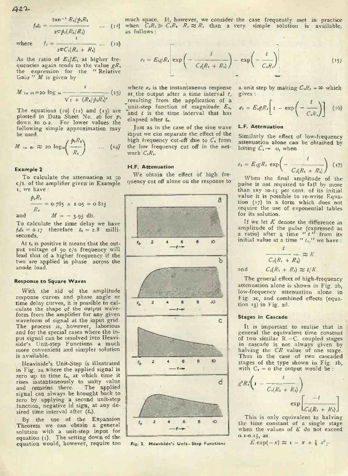
4 2-1--
tan-i R0/P2R3=
247P3(R3/R4)
where f, - ... (12)27TC2(R2 R.)
As the ratio of E3/E1 at higher fre-quencies again tends to the value gR.the expression for the " RelativeGain " M is given by
M in. db =20 log 10 (1.3)V i + (R./M.)2
The equations (to) (u) and (r3) areplotted in Data Sheet No. 46 for t,2down to 0.2. For lower values thefollowing simple approximation maybe used.
p2Ra(M in db Z 20 lOgto -.-
R4... (14)
Example 2To calculate the attenuation at so
c/s. of the amplifier given' in Example1, we have:
p2R,= 0.785 X 1.05 = 0.825
R.and M = - 3.95 db.To calculate the time delay we havefax = o.17 therefore t1 = 2.8 milli-seconds.
At ti is positive it means that the out-put voltage of so c/s frequency willlead that of a higher frequency if thetwo are applied in phase across theanode load.
Response to Square Waves
With the aid of the amplituderesponse curves and phase angle ortime delay curves, it is possible to cal-culate the shape of the output wave-form from the amplifier for any givenwaveform of signal at the input grid.The process Is, however, laboriousand for the special cases where the in-put signal can be resolved into Heavi-side's Unit -step Functions a muchmore convenient and simpler solutionis available.
Heaviside's Unit -Step is illustratedin Fig. 2a where the applied signal iszero up to time to, at which time itrises instantaneously to unity valueand remains there. The appliedsignal can always be brought back tozero by applying a second unit -stepfunction, negative iii sign, at any de-sired titre interval after (t.).
By the use of the ExpansionTheorem we can obtain a generalsolution with a unit -step input forequation (t).. The setting down of theequation would, 'however, require too
much space. If, however, we consider the case frequently met in practice... (III when C.R.>> R3 than a very simple solution is available,
as follows :
e, =t
exp exp(- --C3(R2 + R3) CiR4
where e, is the instantaneous responseat, the output after a time interval t,resulting from the application of aunit -step function of magnitude E1,and t is the time interval that haselapsed after to.
Just as in the case of the sine waveinput we can separate the effect of thehigh frequency cut-off due to C1 fromthe low frequency cut off in the net-work C,R,.
H.F. AttenuationWe obtain the effect of high fre-
quency cut off alone on the response to
to 2 4 6 8 I0
a
tc, 2 4 6 8 _X)
b
to 2 4 8 8
C
to 2 4 6
-t=0-8 io
d
Fig. 2. Heaviside's Unit -Step Functions
-(15)
a unit step by making C.R2-o 00 whichgives :
e3 = Eigl?.11 - exp( - -)] (16)C3R4
L.F. Attenuation
Similarly the effect of low -frequencyattenuation alone can be obtained byletting C1-4- o, when
e3 = E1gR4 exp( (i7)C2(R2 R,)
When the final amplitude of thepulse is not required to fall by morethan say to -15 per cent. of its initialvalue it is possible to re -write Equa-tion (17) in a form which does notrequire the use of exponential tablesfor its solution.
If we let K denote the difference inamplitude of the pulse (expressed asa ratio) after a time " t"- from itsinitial value at a time " to," we have :
KC2(R2 + R.)
and C2(R2 + R3) t/K.The general effect of high -frequency
attenuation alone is shown in Fig. 2b,low -frequency attenuation alone inFig. 2c, and combined effects (equa-tion 15) in Fig. 2d.
Stages in Cascade
It is important to realise that ingeneral the equivalent time constantof two similar R. -C. coupled stagesin cascade is not always given byhalving the CR value of one stage.Thus in the case of two cascadedstages of the type shown in Fig. lb,with C, = o the output would be:
tg2 R43(1
C2(R2 + R2)
-t+ R3)]
This is only equivalent to halvingthe time constant of a single stagewhen the values of K do not exceed0.1-0.15, as
E.exp(-x) -x + x2;.-
exp
1
t
PDF compression, OCR, web optimization using a watermarked evaluation copy of CVISION PDFCompressor

11
FTT
II
IT
HE
HIG
H F
RE
QU
EN
CY
RE
SP
ON
SE
OF
AN
R -
C. C
. AM
PLI
FIE
Rn
.
Ele
ctro
nic
R2=
C°
Eng
inee
rg
(,,
-2 -
20.
DA
TA
SH
EE
T-3
-30
MN
o. 4
5
RC
I-4
--4
0
.ugR
-S.6
50-0
E..c
a3
-660
se:
f4t1
e2f4
t1..
.40 -g
-73
70<
/.2
...°)
,,,=
20I
ogA
/I'D
i-8
4' f
304.
0 0 CC
et) = a.
+ (
P4)
2-I
e2 =
tan
p4-9
-90
-.I
tan
pft
=--
--4
412r
t f4
-10-
1f
-4
2,T
rci R
4-I
1
----
,.--+
-+bi
-12
II
R4
I
Re
I
RI
III
IIII
Iri
2
III
---
.-P4
= S
CI
R4
= f
/f4I
iI
II
-A
II
..I
A
1111 a
III
-712
.Cal
2-3
.4.5
D15
0I 0 05
PDF compression, OCR, web optimization using a watermarked evaluation copy of CVISION PDFCompressor
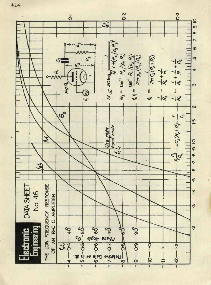
Ele
ctro
nic
Eng
inee
ring
TH
E L
OW
OF
FR
EQ
UE
NC
Y
AN
R -
C.
DA
TA
SH
EE
T
No
46R
ES
PO
NS
E
C. A
MP
LIF
IER
..a...
.,....
...._
_
f5t,
M
82R
IC
2
4t,
figR
a
.ez4
4 -0
.4-4
8xi
'5-
'5
.40
m_5
0E- 3
1
. g.
0
.6.,0
-5.
a1 1:*
oir
R2
1
/M
an: 2
0 lo
g
-0.6
0 0
-,&
-60
6 "0
CL_
_,.s
eright
15t,
117
/4.(R4 /02 R3)2
e2=
tan-I
R4
Ap2
R3)
/f5
hand
t,sc
ale
7..,-
-07
n) 41)
'8-
2 7o
cL
.2
0=
9 -
U
9 6)
-I
tan
R4 /(p2 R3)
f-
5t I
0.9
27rp2 (R3/R4)
f-
/5
2fl'C2(R3+ R2)
/.
/+
/
1010
111
1 2n
R3
-C2
R)
fR
3R
.R
I
/-i +
I_+
I-
i21
I/ 1
11
111
1111
1111
'1-
R4
thP
- --
(R2+
f5
II
1
Rs
_111
1Ra
pi i11
1111
111
R2
11.2
.3.4
.5.6
7 .8
.9 1
0
1
02 03
1.5
23
45
67
8 9
10
PDF compression, OCR, web optimization using a watermarked evaluation copy of CVISION PDFCompressor

March, 1943 Electronic Engineering 425
I
IT WAS HARD TO BELIEVE JOHN HATFIELDJohn Hatfield was a soldier under William III. One night when on guard duty atWindsor Castle he was accused of being asleep at his post. He stoutly denied this,saying that far from being asleep he had actually heard St. Paul's Cathedral clockstrike thirteen. Independent evidence eventually proved his case but his storywas hard to believe at first.There is rather a HATFIELD quality about the claims of DISTRENE (Regd.).This modern insulating material has such outstanding merits that electrical andradio engineers may be forgiven for regarding them a little quizzically. The databelow condenses the story; may we send working samples for practical verification?
SPECIFIC GRAVITY I'06 COMPRESSION STRENGTH 7 TONS PER SQ. IN.
WATER ABSORPTION NIL COEFFICIENT OF LINEAR EXPANSION . '0601
DIELECTRIC CONSTANT 60-106 CYCLES 2'60-2'70 POWER FACTOR UP TO 100 MEGACYCLES '0002-'0003
SURFACE RESISTIVITY (24 HOURS IN WATER) 3 X 10⁶ MEGOHMS
We are the distributors in this country of DISTRENE (Regd.). It is made insheets, rods and tubes and also in powder form for injection moulding. Owing toits low density, it gives more mouldings per pound of material, and has a fastermoulding cycle than any other class of injection moulding powder.
BX PLASTICS LTD., LONDON, E.4 AND ELSEWHERE
Lund Humphries/RX 168
PDF compression, OCR, web optimization using a watermarked evaluation copy of CVISION PDFCompressor
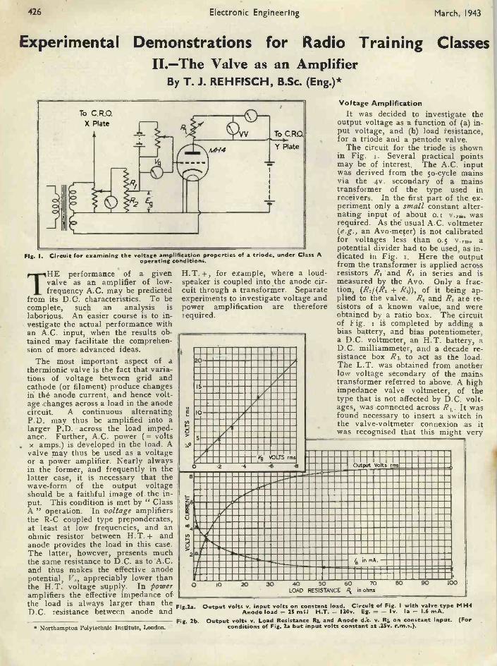
426 Electronic Engineering March, 1943
Experimental Demonstrations for Radio Training ClassesIL-The Valve as an Amplifier
By T. J. REHFISCH, B.Sc. (Eng.)*
Voltage AmplificationTo C. R.O.
X PlateV
T
To C.110.
Y Plate
Fig. I. Circuit for examining the voltage amplification properties of a triode, under Class Aoperating conditions.
THE performance of a givenvalve as an amplifier of low -frequency A.C. may be predicted
from its D.C. characteristics. To becomplete, such an analysis islaborious. An easier course is to in-vestigate the actual performance withan A.C. input, when the results ob-tained may facilitate the comprehen-sion of more, advanced ideas.
The most important aspect of athermionic valve is the fact that varia-tions of voltage between grid andcathode (or filament) produce changesin the anode current, and hence volt-age changes across a load in the anodecircuit. A continuous alternatingP.D. may thus be amplified into alarger P.D. across the load imped-ance. Further, A.C. power (= voltsx amps.) is developed in the load. Avalve may thus be used as a voltageor a power amplifier. Nearly alwaysin the former, and frequently in thelatter case, it is necessary that thewave -form of the output voltageshould be a faithful image of the in-put. This condition is met by " ClassA " operation. In voltage amplifiersthe R -C coupled type preponderates,at least at low frequencies, and anohmic resistor between H.T. + andanode provides the load in this case.The latter, however, presents muchthe same resistance to D.C. as to 'A.C.and thus makes the effective anodepotential, V., appreciably lower thanthe H.T. voltage supply. In poweramplifiers the effective impedance ofthe load is always larger than theD.C. resistance between anode and
Northampton Polytechnic Institute, London.
H. T. +, for example, where a loud-speaker is coupled into the anode cir-cuit through a transformer. Separateexperiments to investigate voltage andpower amplification are thereforerequired.
tn
20
15
10
5
Vg VOLTS rms
O -6 6
It was decided to investigate theoutput voltage as 'a function of (a) in-put voltage, and (b) load 'resistance,for a triode and a pentode valve.
The circuit for the triode is shownin Fig. I. Several practical pointsmay be of interest. The A.C. inputwas derived from the 50 -cycle mainsvia the 4v. secondary of a mainstransformer of the type used inreceivers. In the first part of the ex-periment only a small constant alter-nating input of about 0.5 v.... wasrequired. As the usual A.C. voltmeter(e.g., an Avo-meter) is not calibratedfor voltages less than 0.5 v.rm. apotential divider had to be used, as in-dicated in Fig. 5. Here the outputfrom the transformer is applied acrossresistors R. 'and R. in series and ismeasured by the Avo. Only a frac-tion, (R./ (R. + R2)), of it being ap-plied to the valve. R, and R. are re-sistors of a known value, and wereobtained by a ratio box. The circuitof Fig. i is completed by adding abias battery, and bias potentiometer,a D.C. voltmeter, an H.T. battery, aD.C. milliammeter, and a decade re-sistance box RL to act as the load.The L.T. was obtained from anotherlow voltage secondary of the mainstransformer referred to above. A highimpedance valve voltmeter, of thetype that is not affected by D.C. volt-ages, was connected across RL. It wasfound necessary to insert a switch inthe valve -voltmeter connexion .as itwas recognised that this might very
Output Volts rms
/, in mA.
0 10 20 30 40 50 60 70LOAD RESISTANCE in ohms
80 90 00
Fig.2a. Output volts v. input volts on constant load. Circuit of Fig. I with valve type MH4Anode load = 25 m52 H.T. = I20v. Eg. - Iv. la = 1.6 mA.
Fig. 2b. Output volts v. Load Resistance RI, and Anode cl:c. v. RI, on constant input. (Forconditions of Fig. 2a but input volts constant at .25v. r.m.s.).
PDF compression, OCR, web optimization using a watermarked evaluation copy of CVISION PDFCompressor

March, 19 43 Electronic Engineering 427
Fig. 3a. Output volts V. input volts on constalload as for Fig. 2a but using a pentode tyl
2v., H.T. 150 ScreeMSP4, with Vg. = = v.volts = 75 v. Suppressor grid connected ,
cathode.0
15 Fig. 3b. Output volts v. Load Resistance IF..
and anode and screen d.c. v. RL on consta,input for conditions of Fig. 2b, but with co
input.r.1
stant voltage = .075 v. r.m.s.T 10
..c
IP5 I
r ionl-N3rd Harmonic Distortset
11 in volts
' 4
/a in rnAw
in./.4
/s mA
0 10 20 30 40 50 60 70 80 90RL in ohms x 103
well distort the output voltage. Adouble -beam C.R.O. was available,and both the input and output voltagescould be observed by connecting itsAi and A, terminals to the points in-dicated in Fig i. By adjustment ofthe amplifier controls on the C.R.O.both traces could be made equallylarge, and any distortion thus readilyobserved.
conditions specified inFigs. i and 2(a), the output voltage,V., was measured as the input was in-creased from zero. The output volt-age remained undistorted up to apoint well beyond the range of thevalve -voltmeter. When the inputvoltage just exceeded 2.6v. in this ex-periment the negative half of the out-put voltage became noticeably dis-torted. The wave -form on the C.R.O.did not include the distorting effectwhich the valve voltmeter would havehad throughout, as the latter was dis-connected for each observation. Fur-ther, it is known from theory that theinput voltage and the output voltageacross a purely resistive load shouldhave a phase difference of 18o°. Thisis borne out by the traces on the.C.R.O. screen, where they appear inphase by virtue of the construction ofthe deflector plate system in double -beam tubes itself producing a i8o°phase displacement.
The experimental procedure out-lined above was now repeated forvarying load resistances the inputvoltage being kept constant at o.25v.The results are shown in Fig. 3(a).
It
0
Lt
Both parts of the experiment wererepeated for an MSP4 pentode valve,which replaced the MH4 triode. Thescreen was fed from a tapping on theH.T. battery, no further modificationto the circuit of Fig. z being neces-sary. The results are shown in Figs.2(b) and 3(b).
It must now be stressed that with novalue of input voltage or load was itpossible to obtain a perfectly undis-torted output wave -form from thepentode circuit. The positive halfwas always more " compressed " thanthe negative half, a type of distortionwhich the mathematician attributesessentially to the presence of 2nd har-monics. The point at which the otherhalf of the output wave -form also be-came distorted is marked in Fig. 3(b).It introduces a 3rd harmonic, andindicates an overload point.
b
C
Fig. 4. A.C. equivalent circuits of Class Aamplifiers. (a) and (b) are rigid equivalents,(c) a simplification which usually holds well forpentodes. (a) is most suited for use with
triodes.Discussion of Results
An analysis of D.C. valve charac-teristics leads to the well-knownexpression
AVgR,output voltage, V. - (z)
.12,+ R.where g and R. are the amplificationfactor and internal A.C. resistance ofthe valve respectively. Hence thevoltage amplification factor
V. ARL
m (2)V. RL+R.
= slope of Fig. 2a or 3aUsing the nominal value R.= i 1,000f1for the MH4 triode and the knownvalues of RL and I m I, equation (2)gives ig = 36 compared with thenominal value of µ = 4o for thisvalve. The discrepancy may be at-tributed to the valve specimen or thevalve -voltmeter which was used tomeasure V0. At any rate, the resultsof Fig. 2(a) indicate that m is con-stant in a given circuit, over the rangeof input volts investigated.
Similarly, the results shown in Fig.2(b) satisfy the requirements of equa-tion (2). For RL = R. = i i Kn, V. =
AVg, and from this equation =36 x 0.25/2 = 4.5v., a value somewhatless than that actually obtained. WhenRL is much greater than R. we shouldexpect V. to be approximately equalto µV g, i.e., to qv. The highest valueactually observ,ed was 8.6, which wasnot very far off the theoretical value.
Fig. 5. Circuit for examining the properties of an amplifying circuit under Class A operatingconditions.
PDF compression, OCR, web optimization using a watermarked evaluation copy of CVISION PDFCompressor

428 Electronic Engineering March, 1943
10
8
6z
a.
0-I- 2
8
7
III
IMO
.5.5n eso18o,o.154a
= la
n=30
O 20 30
100
80
,60
-140
20
40 50in ohms
60 70 80
5000R2=2. a -30.60.,8 a.--
0 utputp ewer
Necative Bias volts
D rive Jolts rms
a
O to 30 40 50R in ohms
60 70
6
Fig. 6. Output power v. load resistance for constant grid conditions. Vg. = 1.1 volt r.m.s.Eg. - 2v., Ea = 118, la = 13.2 mA.
Fig. 7. Output powerBias Volts Eg }v. load resistanceDrive Volts Vg
for max. undistorted power output with each value of Rs n 18.
Of course, V. = AV, can never be ob- of the three constituents of Fig. 4.tained in practice, because distortion Second harmonic distortion, for ex -will eventually set in as RL is furtherincreased.
The A.C. Internal resistance. Thecurve of Fig. 2(b) is similar to thecurves, of output -voltage vs. load im-pedance for a source having internalresistance. (cf. the curve with thosein the first of these articles). Hencethe A.C. properties of a Class Aamplifying valve circuit may be re-presented by means of a valve" equivalent circuit." In the versionsuggested in Fig. 4 a negative signhas been attached to the internale.m.f. so as to account for the pre-viously noted phase difference of i8o°between V. and Vg, and a circle en-closes R. and -µV, to indicate theirpresence within the valve. No difficul-ties arise in regarding the valve as asimple A.C. generator if one bears inmind that the equivalent circuit refersto A.C. only. Distortion, input 'im-pedance, feedback, etc., can always beaccounted for by suitable modification
ample, may be introduced by insert-ing a generator of twice the frequencyof V, in series with the one actuallyshown. (See Terman " RadioEngineering " for details of thismethod).
Comparing the two valves, the out-standing feature of Fig. 2(b) is thatits slope is over twice that of Fig. 2(a)although the mutual conductance ofthe triode (3.6 mA/v) is greater thanthat of the pentode (2.4 mA/v). Agreater sensitivity is therefore obtain-able with the pentode. This valve,however, gives greater distortion thanthe triode. Hence, where distortion -less amplification is vital, as in audiowork, pentodes may only be used itgreat care is taken to compensate fortheir inherent distortion, for example,by negative feedback and push-pullcircuits.
The V. - R,, characteristic, Fig.3(b) for the pentode is of the samegeneral shape as for the triode. The
fact that it is so obviously more linearis due to the greater value of R. com-pared to RL for the pentode. As amatter of fact, equation (2) may be re-written as
-µV,RLIR.
1-FRLIR.-gmRL Vg
for the usual pentode amplifier. ThusV. is approximately proportional toRL. A form of A.C. equivalent cir-cuit most suitable for pentodes isshown in Figs. 4(b) and 4(c). Thecurrent /,(;:-.., - gmVg) flows into theparallel combination of R. and RL,the proportion flowing into the ex-ternal resistance RL depending on theratio RL/R.. Usually, the shuntingeffects of R. may be neglected, andthe simplified circuit of Fig. 4(c)may be used.Power Amplification
Fig. 5 is a diagram of the circuitfor investigating the properties of aClass A power amplifier. It is simi-lar to the circuit, Fig. r previouslyused, except that the load is now ofthe coupled type; the small universaltransformer described in the firstarticle was used to couple the load R.into the anode side of the valve. Adouble -beam C.R.O. was again turnedto good account in comparing thewave -forms of the input voltage withthe voltage developed across RL (andhence also the current in RL). Outputpower was measured in the usual way(volts x amps). The alternating in-put, Vg, was derived from a r,000 c/s.audio oscillator, and its magnitudecould be both adjusted and measured.The only additional feature worthnoting in Fig. 5 is the resistor placedin series with the grid. Its value is afew thousand ohms, and its purpose isto make noticeable the flow of gridcurrent in the case of the appliedalternating P.D. driving the gridpositive. If this occurs the actual grid -cathode P.D. becomes disturbed, andhence the output voltage. This, ofcourse, is what happens in an actualpower amplifier excited by a sourceof appreciable internal impedance. A2 -volt battery " power " triode-actually a Mullard PM2A-was usedin these experiments.
In the first part, moderate gridbias, Eg, and drive, V., were used andkept constant as the load R,, wasvaried. The resulting load current,/L, was observed. The output power(iL2RL) was calculated, and is shownplotted against Rz in Fig. 6. This wasrepeated for another transformerratio, n.
In the second part of the experi-ment the output current and outputpower were again measured as RT, wasvaried, but this time for any givenvalue of RL, both V, and E, were ad-
Vo _-gmRLV,
PDF compression, OCR, web optimization using a watermarked evaluation copy of CVISION PDFCompressor

March, 1943 Electronic Engineering 429
Anole E19ciency
i.Anode D.C.
8
6
4
0 10 20 30 40 50R2 in ohms
60 70 .80
Fig. 8. Anode d.c. and Anode efficiency v. load resistance Rs for conditions of F g. 7.
justed for maximum undistorted out-put power. The latter condition wasactually met by observing the trace inthe output voltage on the C.R.O.screen, and, each time, increasingV5 and simultaneously adjusting E,until distortion became just noticeableat both top and bottom of the outputwave -form. This procedure may ap-pear somewhat difficult, but provideda picture of the input wave -form isalso obtained on the screen it becomesquite simple after a short while.
The following headings of the listof observations may help, as the num-ber of dependent variables in the ex-periment are large :-
which, with correct matching, be-comes a maximum of magnitude(p V.)2/ 4R. ;here µ=13, V.= iv, and R.=5,000n.. maximum output power,
(13 X 1.1)2(PL)me. - - It> mW,
4 x 5,000which checks up well with Fig. 6.
In the second part of this experi-ment, however, it was seen that moreoutput power is obtainable if the gridbe driven harder for a given load. Thegrid drive is limited on its positivepeaks, though, 'by the condition(V,) p.nk = E5, and, at the negative
RLohms
Vg
volts-Egvolts
IL
mAPLIL'RL
mW
la
mA lava
too PLis the " efficiency "
output power
total power suppliedThe more important results and theirderivatives are plotted against RL InFigs. 7 and 8.
Discussion of ResultsThe relationship between output
power, PL, and load resistance, RL, inthe case of constant grid conditionsis analogous to the case of the simpleA.C. generator with internal resist-ances, /21, already referred to in theprevious article. It was stated therethat the output power, PL, is a maxi-mum when the load, RL, is equal toRipe.. With the valve, R1 = R., andthe calculated condition for matchingis shown in Fig. 6 for two differentvalues of transformer -ratio, n. Thevalue R. = 5,000i was obtained fromthe D.C. characteristics of the valvespecimen actually used. Moreover,the output power is
PVgR.+RLx RL,
end, by the bottom curvature of thedynamic mutual characteristic. In-spection of Fig. 7 indicates that thisdanger region recedes until RL = 500as the' load is increased. WhenRL = 502 the output power de-creases, and at this point the peak ofthe drive voltage approaches thevalue of the static cut-off bias.
Thus, when V, and RL both in-crease, we can state that there are twoconflicting results so far as power isconcerned. In the former case, thetotal A.C. power generated increases,but when RL is increased the total A.C.power generated decreases, althougha larger share of this power is thendeveloped in RL.
In terms of algebra, total A.C.power = (µV5)21R. + RL. This in-creases when RL is constant and V5 in-creases, but decreases if V5 is con-stant and RL is increased. At thesame time the power in RL is a frac-tion of the total A.C. power given by= RL IR.+ RL which increases as RLincreases. Thus a larger share is de-veloped in RL as RL increases. Whenthese contrasting properties are con-sidered for an idealised valve (i.e.,
one whose characteristics are straightlines without bottom curvature) it canbe shown that /2, = 2R. is the condi-tion for maximum output power.The expression for the latter thenbecomes
(µV,)2 x 2R. µ'VePL -
(R. + 2R.)2 4.5 R.Fig. 7 indicates that this conditionobtains with RL = 30f2.By calculation,
2R. 2 X 5,000RL -
n' 18'The output power PL, by calculation
13' X 3.5'- 92 mW,
4.5 X 5,000and actually came to 91 mW on thegraph. The maximum permissible griddrive was about 4v r.m.s., and could,of course, have been forecast from theD.C. characteristics of the valve.
D.C. and A.C. EfficienciesThe anode d.c. values and anode
efficiency are shown in Fig. 8. Themaximum efficiency reached is 17.5per cent., which is somewhat less thanthe theoretical 25 per cent. for anidealised valve. It should be notedthat this max. efficiency occurs at aload larger than that correspondingto max. A.C. efficiency. As RL is in-creased beyond the value 2R./n' andthe grid is biased further back, theD.C. power supplied to the anode fallsoff more rapidly than the A.C. poweroutput until a point is reached whenno further appreciable increase of V5drive is possible. Remembering thatpractically all the D.C. power notconverted into A.C. power is dis-sipated at the anode in the form ofheat, it is not surprising that mucheffort has been spent on devising moreefficient methods of amplification suchas Class B, Class C, and push-pulloperation.
In conclusion, it should be notedand stressed that these considerationsdo not in any way indicate faults inthe equivalent A.C. circuit of thevalve. It is still correct for A.C.power relations in the actual valve
' circuit. In order, however, to obtaininformation on just how large V, andhow small I. and E. (the anode volt-age) can be made the D.C. character-istics of the valve must be studied oran experiment performed. It is as ab-surd to maintain that this means abreakdown in the equivalent valve cir-cuit as to say that the electrical ch-cuit diagram of an amplifier is incor-rect because the weight of its chassiscannot be deduced from it !
Thanks are due to Mr. M. Nelkon,B.Sc., A.K.C., for his help with theM.S.
PDF compression, OCR, web optimization using a watermarked evaluation copy of CVISION PDFCompressor
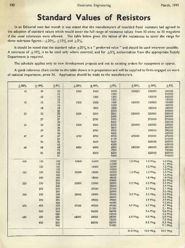
430 Electronic Engineering March, 1943
Standard Values of ResistorsIn an Editorial note last month it was stated that the manufacturers of moulded fixed resistors had agreed to
the adoption of standard values which would cover the full range of resistance values from 10 ohms to 10 megohmsif the usual tolerances were allowed. The table below gives the values of the resistances to cover the range forthree tolerance figures -±20%, +10% and +5%.
It should be noted that the standard value +20% is a " preferred value " and should be used wherever possible.A tolerance of ±10% is to be used only where essential, and for ±5% authorisation from the appropriate SupplyDepartment is required.
The schedule applies only to new development projects and not to existing orders for equipment or spares.
A quick reference chart similar to the table shown is in preparation and will be supplied to firms engaged on workof national importance, price 3d. Application should be made to the manufacturers.
±20% +10% +5% +20% ±10% +5% ±20% ±10% +5%
10 10 0 1000 1000 000 100000 100000 000001 100 10000
12 2 1200 200 120000 200003 300 30000
IS 15 5 1500 1500 500 150000 150000 500006 600 60000
18 8 1800 800 180000 8000020 2000 200000
22 22 22 2200 2200 2200 220000 220000 22000024 2400 240000
27 27 2700 2700 270000 27000030 3000 300000
33 33 33 3300 3300 3300 330000 330000 33000036 3600 360000
39 39 3900 3900 390000 39000043 4300 430000
47 47 47 4700 4700 4700 470000 470000 47000051 5100 510000
56 56 5600 5600 560000 56000062 6200 620000
68 68 68 6800 6800 6800 680000 680000 68000075 7500 750000
82 82 8200 8200 820000 82000091 9100 910000
100 100 00 10000 10000 0000 1.0 Meg. 1.0 Meg. .0 Meg.10 1000 .1 Meg.
120 20 12000 2000 1.2 Meg. .2 Meg.30 3000 .3 Meg.
150 150 50 15000 15000 5000 1.5 Meg. 1.5 Meg. .5 Meg.60 6000 .6 Meg.
180 80 18000 8000 1.8 Meg. .8 Meg.200 20000 2.0 Meg.
220 220 220 22000 22000 22000 2.2 Meg. 2.2 Meg. 2.2 Meg.240 24000 2.4 Meg.
270 270 27000 27000 2.7 Meg. 2.7 Meg.300 30000 3.0 Meg.
330 330 330 33000 33000 33000 3.3 Meg. 3.3 Meg. 3.3 Meg.360 36000 3.6 Meg.
390 390 39000 39000 3.9 Meg. 3.9 Meg.430 43000 4.3 Meg.
470 470 470 47000 47000 47000 4.7 Meg. 4.7 Meg. 4.7 Meg.510 51000 5.1 Meg.
560 560 56000 56000 5.6 Meg. 5.6 Meg.620 62000 6.2 Meg.
680 680 680 68000 68000 68000 6.8 Meg. 6.8 Meg. 6.8 Meg.750 75000 7.5 Meg.
820 820 82000 82000 8.2 Meg. 8.2 Meg.910 91000 9.1 Meg.
10.0 Meg. 10.0 Meg. 10.0 Meg.
PDF compression, OCR, web optimization using a watermarked evaluation copy of CVISION PDFCompressor

March, 1943 ElectronicjEngineering 431
P.14
One too manyIN these days of high endeavour the manufacturer must sometimes
feel rather like an anxious juggler, half wondering whether thenext ticklish problem will be one too many for him. With all hisingenuity in organization he may find it impossible to increaseoutput still further without some impairment of quality. It is herethat Simmonds can help.
The Simmonds products were designed to solve preciselythis problem and solving it they are, all over the country. Theyare calculated to save time, to save material and to simplify assembly:in a word, to speed up production all round without fuss or delay.
SIMMLONDSThe Creative Impulse in
AERONAUTICAL, INDUSTRIAL & MARINEConstruction
THE SIMMONDS NUT PINNACLE NUT SPIRE NUTSIMMONDS GAUGES, INSTRUMENTS AND CONTROLS
FRAM OIL & ENGINE CLEANER
SIMMONDS AEROCESSORIES LTD.GREAT WEST ROAD, LONDON
A COMPANY OF THE SIMMONDS GROUP
LONDON, MELBOURNE, PARIS, NEW YORK.
PDF compression, OCR, web optimization using a watermarked evaluation copy of CVISION PDFCompressor

432 Electronic Engineering Mai:ch, 1943
A Circular Aerial for(From Q.S.T.-Nov. 1942)
AT a paper presented before theSummer Convention of the In-stitution of Radio Engineers,
M. W. Sheldorf described a "circularend -loaded folded dipole " whichradiates equally well in all horizontaldirections and has very little verticalradiation.
Designed mainly for f.m. broadcast-ing, the aerial is as simple as possiblein construction and can be mounted onan earthed metal pole. Individualaerials can be stacked to form a multi-unit system. While the resonancecharacteristic is not broad enough fortelevision transmission it is suffi-ciently good for wide -band frequencymodulation. The resonant frequencyis adjustable after installation.
HORIZONTAL
PATTERN
VERTICAL
PATTERN
Fig. 3. Simple loop aerial. To obtain atrue circular pattern in the horizontal planethe total length of loop must be smallenough in comparison with the i-wavelengthso that the current is substantially the same
in all parts.The final aerial design was evolved
from a cubical aerial consisting of twohorizontal sets of four half -wave ele-ments each, the elements of a set be-ing arranged in the form of a square.Subsequent work showed that thesame effect could be secured by re-placing the square set of four ele-ments by a pair of elements arrangedin the form of a V having a 9o -degreeopening, as shown in Fig. i. Thisgave the horizontal pattern also shownin Fig. i; the shape could be con-trolled by altering the angle betweenthe arms of the V, an angle smallerthan 90 degrees giving an improve-ment over the pattern shown. How-ever, the 'aerial was still bulky andthe elements had to be insulated fromthe support.
The next step is shown in Fig. 2,where the aerial consists of two quar-ter -wave sections each bent in theform of a U having sides of equallength, the two sections being fitted
U. H.F.
Fig. 1. 90° V -aerial and radiation pattern.Fig. 2 (below). Overlapping square aerials.together in the form of a square withtwo of the sides overlapping. Thisgives a circular radiation pattern,since the currents in the overlappingsections are in phase and the resultant" effective " current tends to be uni-form around the square. This type ofaerial is also obviously much smallerthan the V or cubical arrangements.Because of the capacity between theadjacent sections of the aerial, theoverlapping square aerial is prac-tically the equivalent of a loop. aerial
FOLDED /ERIAL
111111111M
Current Distribution1111111111111111
END CAPACITY ADDED
ELEMEANTS8ESIT INCIRCLE
18110Fig. 5. The evolution of the circular aerial
from a folded dipole.
having capacity loading, as shown inFig. 3.'
The final system used is shown inFig. 4. Because the radiation re-sistance of a circular aerial such asthat shown in Fig. 3 is quite low, asecond element was added to providea step-up impedance transformation,using the principle of the foldeddipole.' The effective length of theelements, including the loading of theena capacity C, is one-half wave-length overall. Point D, Fig. 4, is atearth potential and the aerial there-fore can be mounted directly on ametal supporting pole at this point,without insulation. In the practicalaerial the elements are made of steelpipe formed into a circle having a dia-
HORIZONTAL
PATTERN
Pero toI Neutral Plane
E Y:A eV.
- -
o
1
s
Fig. 4. The circular aerial described inthe text.
meter of 33 inches, for a centre fre-quency of about 46 Mc/s. This com-pares with a length of slightly overio ft. for a half -wave dipole at thesame frequency.
Fig. 5 shows the development of theaerial from the plain folded arrange-ment. In the top drawing, the cur-rent distribution is close to that char-acteristic of an ordinary half -waveaerial. By adding end capacity,Stage 2, the current distribution ismade more uniform because an ap-preciable current flows into the endcapacitors. In the final stage theaerial system is formed into a circlewith the end capacitors facing eachother to form a condenser.
The relative diameters of the twoelements A and B determine the mag-nitude of the impedance step-up. Ithas been found experimentally thata wide range of impedance changecan be obtained. In the commercialdesign the terminal impedance isabout 35 ohms, at resonance at ' 46Mc/s. when the aerial is mounted on
PDF compression, OCR, web optimization using a watermarked evaluation copy of CVISION PDFCompressor

March, 1943 Electronic Engineering 433
THE practice of using X-rays asa method of inspection in indus-try is rapidly being adopted, and
numerous new applications are con-stantly being found, with the resultthat X-ray equipment is now beingdesigned for specific types of work.An example of this is the new M. tooIndustrial X-ray Unit developed byMessrs. Philips Lamps, Ltd., Shaftes-bury Avenue, London, W.C.2.
The equipment consists of an H.T.Transformer, a shockproof and ray -proof X-ray tube and a portable con-trol table. The shockproof X-raytube is provided with forced air cool-ing and connexion to the H.T. Trans-former is effected by means of twoshockproof H.T. cables. The H.T.transformer is accommodated on thebase of a mobile trolley and theshockproof X-ray tube is mounted ona vertical column, provided with uni-versal movements so that the X-raytube can be angulated in virtually anydirection. For ease in transportation,the control table is mounted on an
' angle iron frame over the H.T. trans-former, and can be removed andplaced if desired, on a bench in anadjoining room. Alternatively, theframe which is also removable can beused as a stand. Connexion to theH.T. transformer from the controltable is made via a multi -core cable.
This type of equipment is capableof delivering up to too kVp, and thecontrols are of a very simple nature.With this apparatus it is possible toexamine up to in. steel and 4 in. ofaluminium by the radiographicmethod. It is eminently suitable forthe inspection of electrical assemblies,thin gauge spot welding and plasticmaterials, etc. The unit design of theequipment readily lends itself for in-corporation in a conveyor belt systemfor the continuous visual inspection ofsuch commodities as sparking plugsand moulded assemblies.
A New Industrial X -Ray Unit
A Circular Aerial (continued)
a 4 -inch diameter steel pole. Withpoles of larger diameter the radiationresistance decreases because of out -of -phase currents induced in the sum -face of the pole.
Since the aerial is appreciablysmaller than an ordinary dipole, someloss of signal strength is to be ex-pected as compared to the latter. How-ever, it turns out that this loss is onlyone decibel as compared to a verticaldipole (which also has a uniformhorizontal pattern). The aerials canbe stacked vertically to increase thefield strength, and it has been foundthat optimum gain is obtained whenthe spacing between units is about onewavelength. The gain in decibelsover a vertical half -wave aerial, as a
.c;vzzTc0
t
NO. O'r BAYS)
2 4 6 8 if
4
function of number of aerials or" bays," is shown in Fig. 6. It canbe seen that doubling the number ofelements results in approximately 3db. gain. This is to be expected inview of the fact that the mutual im-pedance between aerial units or bayshas been determined experimentallyto be very low, when the spacing isone wavelength, hence the bays actalmost independently of one another.
REFERENCES.1 A. Alford and A. G. Kandoian, " Ultrahigh -
Frequency Loop Aerials " A.I.E.E. Trans. Sup-plement, 1940.
2 P. S. Carter, " Simple Television Aerials," RCARev. October, 1939.
Fig. 6. Gain of circular antenna over avertical half -wave dipole. Bay spacing is
I wavelength.
PDF compression, OCR, web optimization using a watermarked evaluation copy of CVISION PDFCompressor

434 Electronic Engineering March, 1943
Straight Line Rotating Plate Condensers with LargeAngle of Rotation
IN high grade special appliancesfor ultra short wave engineeringspecial rotating plate condensers
are desirable for selecting from alarge number of u.h.f. channels. Theyshould fulfil the following require-ments :
(a) small space(b) high accuracy of tuning(c) easy adjustment(d) large angle of rotation(e). linear relation between capacit-
ance and angle of rotation.How these requirements may best be
fulfilled is described in a recent pub-lication of E. Leider and 0. Zinke:mIn the following an abstract is givenof its principal contents.
With the usual shape of statorplates covering one quadrant andhaving a circular face neither a. rotorwith regularly stepped circularquadrants nor one in which the circu-lar faces were replaced by spiralsgave a straight capacitance character-istic. An improvement is obtainableby cutting the stator face as well asthe rotor face in a spiral.
F ig. i and 2 show the usual type ofa rotating plate condenser if insteadof the customary angle of 18o° anangle of 270° is chosen for the rotorwhile the stator angle is 90°. InFig. t the rotor face has three circu-lar steps, while the stator face is alsocircular. In Fig. 2 the rotor faces areformed by spirals. As is shown inFig. 3 the capacitance is by no mean,proportional to the angle of rotation.Calling C = capacitance
e = the dielectric constantF = the active arean = the sum of stator and
rotor plates diminishedby
d distance of plates.we have
C=eFn
Fig. I (left). Condenser with stepped circularfaces of rotor, stator face circular.Fig. 2 (right). Condenser with spiral faces ofrotor, stator face circular.
Elektrotechnische Zeus. 63, PP. 433-436, Sept. 24,1942
Stator
Angle of rotation 0° 30° 60° 90.
a ,
K-aet
ar0° + K- (cm2)
astrl (cm)
0
1.0
1.0
0.48
1.48
1.22
0.96
1.96
1.40
1.44
2.44
1.56
Rotor
Angle of rotation 0° 30° 60° 90°
aK-
asta
Ro2 + K- (cm2)ast
R (cm)
0
2.44
1.56
0.48
2.92
1.71
0.96
3.40
1.84
1.44
3.88
1.97
Angle of rotation ' 120° 150° 180°
aK-
alta
Ro1 ± K- (cm2)ast
R (cm)
1.92
4.36
2.09
2.40
4.84
2.20
2.88
5.32
2.31
Angle of rotation 210° 240° 270°
aK -
asta
Re + K - (cm2)aet
R (cm)
3.36
5.80
2.41
3.84
6.28
2.51
4.32
6.76
2.60
As we require a linear re ation be-tween capacitance C and angle ofrotation a we get
K KF = - a and therefore dF = - da
2 2
The constant K/2 is then given by therelation
K C... d2 en a ..x
and has the dimension of an area.Calling the variable rotor radius R
and the variable stator radius r andreferring to Fig. 4 we see that thearea F for a certain angle of rotationa is given by the relation
a a a
F da - da = if(R2 - r') da2
thereforedF
= RR' - r = K/2da
or for a given angle a= +K
Similar relations are found for thesecond and third quadrant.
In order to get smooth transitionwhen passing through a = 900 or -more general -through ast, i.e., theangle of the stator plate, it is essen-tial that r at angle ast equals R.. The
tO
pf 6
4 /.90 90 ,r, aro vd'
Fig. 3. Characteristics with circular statorface.(I) Rotor face stepped circular.(2) Rotor face stepped spiral.
PDF compression, OCR, web optimization using a watermarked evaluation copy of CVISION PDFCompressor
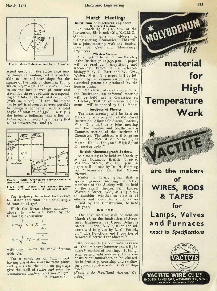
March, 1943 Electronic Engineering 435
Fig. 4. Area F determined by a, R and r,
actual curve for the stator face maybe chosen at random, but it is prefer-able to use a linear slope for thesquare of the radii as shown in Fig. 5which represents the connexion be-tween the face curves of rotor andstator for three quadrants correspond-ing to a total angle of rotation of 2700(with ast = 90°). If for the statorangle 3o° is chosen it is even possibleto design a condenser with a totalangle of rotation of 330°. In Fig. 5the index 2 indicates that a lies be-tween a.: and 2a..; the index 3 thata lies between 2a. and 3ast.
R,r
-
.4;27-1; R!, -2K
last
Rz
3K
cz O ast last 3a,
Fig. 5. (right) Connexion between the facecurves of stator and rotor.Fig. 6. (left) Actual face curves for con-denser with total angle of rotation of 270`.
Fig. 6 shows the actual face curvesfor stator and rotor for a total angleof rotation of 270°.
With the linear slope mentionedabove the radii are given by thefollowing expressions
a=,\/ 702 K -
a.t
R R.' + Ka
ct.t
with other words the radii ittcreasewith Va.
For a condenser of C... = xopFhaving one stator and two rotor platesand ro = r cm. the table on page 434give the radii of stator and rotor fora maximum angle of rotation of no°.
R. NEUMANN.
March MeetingsInstitution of Electrical Engineers
Ordinary Meetings.On March 25 at 5.30 15.m. at the
Institution, Sir Frank Gill, K.C.M.G.,O.B.E., will give an address on" Engineering Edonomics." This willbe a joint meeting with the Institu-tions of Civil and MechanicalEngineers.
Wireless Section.At a meeting to be held on March 3
at the Institution at 5.30 p.m., a paperwill be read on Amplifying andRecording Technique in Electro-biology " by G. Parr and W. GreyWalter, M.A. The paper will be fol-lowed by a demonstration of theelectrical potentials produced by thehuman brain.
On March 16, also at 5.30 p.m. atthe Institution, an informal meetingwill be held and a .discussion on" Factory Testing of Radio Equip-ment " will be opened by F. L. Hogg.
Institute of Physics.The next meeting will be held on
March 17 at 2.3o p.m. at the RoyalInstitution, Albemarle Street, London,W.I. This will be a joint meetingwith the London and South -EasternCounties section of the Institute ofChemistry. The address will be givenby E. D. Eyles, B.Sc., A.Inst.P., ofMessrs. Kodak, Ltd., on " High SpeedKinematography."
British Kinematograph Society.At a meeting to be held on March 17
at the Gaumont British Theatre,Wardour Street, WI, at_ 6 p.m., apaper will be read by Dr. N. Flemingon " Acoustics and the MotionPicture."
Notice is hereby given that aspecial general meeting of activemembers of the Society will be heldat the small theatre, Film House,Wardour Street, W.', at 5.45 p.m.,to consider whether an election ofofficers and committee shall, as re-quired by the Constitution, be heldthis year.
Brit. I.R.E.The next meeting will be held on
March 26, at the Institution of Struc-tural Engineers, II Upper BelgraveStreet, London, S.W.i, when tIA ad-dress will be given by L. C. Pocock,on " The Functions and Properties ofAcousto-Electric Transducers."
Do realise that a poor view is takenof the " heavy -hammer -and -a -light -heart " method of working. If thingsstick or get tight suddenly, there's anobstruction somewhere. to be cleared.As in dentistry, courtship and sardine -tin opening, persuasion is better thanforce.(From a de Havilland Aircraft CoAdvt.)
materialfor
HighTemperature
Work
are the makersof
WIRES, RODS& TAPES
forLamps, Valvesand Furnacesexact to Specifications
VACTITEIMPF
zoN D
VACTITE WIRE Co LTD..19 QUEEN ANNE'S GATE, WESTMINSTER, S.W. I
TELEPHONE: WHITEHALL 2552
PDF compression, OCR, web optimization using a watermarked evaluation copy of CVISION PDFCompressor

436 Electronic Engineering March, 1943
NOTES FROMTHE INDUSTRY
B.S.I.British Standard Electrical Glossary
At the outbreak of war a revision ofthe B.S. Glossary of Terms used inElectrical Engineering had alreadycommenced. The progress has neces-sarily been slow, but it has nowreached a stage where publication insections can begin. Under presentconditions the main portion of thework will be issued in 8 parts.
Terms relating to Telecommunica-tion, which were given in Sections 9and io of the 1936 Edition of theGlossary will be issued separately indue course as a revision of B.S. 204.
Each part will be published at 2s.Part t is now ready, the others willfollow at short intervals. Orders forother parts may now be placed.
Copies may be obtained from thePublications Department, BritishStandards Institution, 28 VictoriaStreet, London,
Inserted Tip Drills for Economy inHigh Speed Steel
The idea of using drills with in-serted tips is not new, but in view ofthe urgent need for the utmosteconomy in high speed steel, it is sug-gested that the principle might withadvantage be applied more extensivelyat the present time.
It is true that the drills have certainlimitations. They cannot, for instance,be used for drilling from the solid,although they are perfectly satisfac-tory for opening out holes producedby a pilot drill, or by piercing.
One type of drill has two flutes andthe other four. The fluted stem andtapered shank in each instance aremanufactured from carbon steel, andthe inserted tips are made from 18 percent. tungsten high speed steel.
The 2 -flute drill is provided with atube for carrying cutting fluid to thecutting edge.
The saving in high speed steel willbe appreciated from the followingfigures :-
The 2 -flute drill is 2 inches in dia-meter, and the overall length is 2Iinches. The total weight is 2o lb., ofwhich only 6 oz. is high speed steel.The 4 -flute drill is 25 inches long over-all, and 2.70 inches in diameter. 1 lb.of high speed steel is used for the tipand 46 lb. of carbon steel for the bodyand shank of the tool.
Production and Engineering Bul-letin, Vol. 2, No. 4, 1943.
Conference on X -Ray AnalysisThe Institute of Physics is arrang-
ing a second conference to take place
In the new R.C.A.research labora-tories the opticallaboratory bayshave hatches inthe walls to per-mit of long focusset-ups for tele-vision testing. Thebenches are fittedwith numerouselectrical outletsas shown and inaddition are pipedfor air gas, water
H. and 0.
in Cambridge on April 9 and to. Theprovisional programme includes a lec-ture on " Future Developments in X -Ray Crystallography " by Prof. J. D.Bernal and discussions on " Quanta-tive Treatment of Powder Photo-graphs," " The Fine Structure ofX -Ray Diffraction " and " LineBroadening."
Further particulars may be obtainedfrom the Secretary of the Institute ofPhysics, The University, Reading.
Catalogues ReceivedResistances and Resistance Networks
Messrs. Muirhead's publicationC. Io2A gives full information on therange of resistance boxes, slide wiresand attenuators manufactured bythem. Their " Munit " construction,in which the various components areassembled in metal boxes with drilledflanges on two sides, enables appara-tus such as Wheatstone bridges,special attenuators, etc., to be madeup in semi -permanent form from stockcomponents.
Preciion slide wires of constant in-ductance can be supplied in circularform with resistances from 0.5-10 t1.
There is also an attenuator avail-able wound to 75 ohms impedance foruse with H.F. cables at frequenciesup to several Mc/s. Muirhead & Co.,Elmers End, Beckenham.
Potentiometers and Stud SwitchesMessrs. Painton & Co. (Kings-
thorpe, Northampton) can supply studswitches of instrument quality withberyllium copper brushes (if required).It has been found that the use of thesebrushes lowers the contact resistanceappreciably and that the " noise " onrotating the switch is reduced.
The type CV.z5S potentiometer is ofmassive construction with a substan-tial metal shielding case. Resistancesfrom too to 50,000 ohms. Dissipation25 watts. Vitreous enamelled andother types of fixed resistances are alsomanufactured.
Further Letter from Dr. J. R. Baker
SIR,-A friend has pointed out tome that one sentence in my letter inthe January number of ELECTRONICENGINEERING implies that Prof. J. D.Bernal introduced contradictory pas-sages into his book, The SocialFunction of Science, from unworthymotives. I wish to retract this im-plication as to Prof. Bernal's motives.The retraction is particularly neces-sary because the discussion has beenclosed and Prof. Bernal is thus pre-vented from answering in yourcolumns.-Yours faithfully,
JOHN R. BAKER.
PDF compression, OCR, web optimization using a watermarked evaluation copy of CVISION PDFCompressor

437March, 1943 Electronic Engineering
Aletala3tikRUBBER -TO -METAL WELD
plus3eientilic application
METALASTIK pioneered the high -dutyrubber -to -metal weld, thereby vastly increas-ing the scope of rubber in combating vibration.
But the attractions of that manufacturingtechnique must not be allowed to obscurethe fundamental requirement ; sound designbased on knowledge of the behaviour of rubberunder all conditions.
That knowledge we possess ; it is at the dis-posal of all who have vibration problems, andit is always increasing.
The photographs show stages in the manufacture ofour patent 'cross' -type mounting : the smallest size issuitable for instruments and carries a pound load, thelargest, for heavy machines, carries a ton ; this rangecovers a variety of frequencies. This simple design hasoutstanding features ; the bonding areas on inner andouter members are equal, stress concentrations areavoided ; the rubber is stressed in shear, and is thusused to the best advantage.
YOUR VIBRATION PROBLEMS ARE WELCOME
Metalastik Ltd. Leicester.
METALASTkKANTI
PDF compression, OCR, web optimization using a watermarked evaluation copy of CVISION PDFCompressor

438 Electronic Engineering March, 1943.
ABSTRACTS OFELECTRONIC LITERATURE
TELEVISIONAnalysis, Synthesis, and Evaluation ofthe Transient Response of Television
Equipment(A. V. Bedford and G. L Fredendall)The sharpness of detail in a tele-
vision picture is directly dependentupon the capability of the transmitterfor the transmission of abruptchanges in picture half tone. A suit-able test signal is a square wave ofsufficiently long period.
Rules are deduced for the evalua-tion of the subjective sharpness to beexpected in transmitted pictures andmay be applied when the square waveresponse of the transmitting apparatusis known. Rapid chart methods havebeen devised for (s) the analysis of asquare wave output into sine -waveamplitude and phase response and (2)the synthesis of a square waveresponse from a given set of ampli-tude and phase characteristics. Analy-sis furnishes an immediate solu-tion to the familiar but troublesomeproblem of finding the sine -wave char-acteristics of television apparatus.The four aspects of the application ofsquare waves to television, i.e.,measurement, analysis, synthesis andevaluation are presented as a basis fora unified and complete technique.
The authors hope that this paperwill be a contribution to the generalproblem of working out electricalspecifications for television transmit-ters and other television apparatus,giving information regarding thesteepness of rise and the amplitude ofoverswing of the square waveresponse.
-Proc. I.R.E., Vol. 30, No. io(1942), page 440.
A Portable High Frequency SquareWave Oscillograph for Television(R. D. Kell, A. V. Bedford and H.W. Kozanow-
ski)A portable high frequency oscillo-
graph for television is described bywhich a square wave (ioo-kilocycle)response may be viewed as a dottedwave and readily recorded as a seriesof readings. The dots are spaced at5/30-(or 1/20) microsecond intervals.No electrical connexion is requiredbetween the oscillograph and thesquare wave generator other than thatestablished through the apparatusunder test since the synchronoussweep and timing dots are derivedfrom the square wave response of theapparatus. Circuit diagrams of thesquare wave generator and squarewave oscillograph are given.
-Ibid., page 458.
THERMIONIC DEVICESA Diffraction Adapter for the Electron
Microscope(J. Hillier, R. F. Baker and V. K. Zworykin)An adapter has been developed
which allows a. conventional electronmicroscope to be used interchange-ably as an electron diffraction cameraor an electron microscope. The adap-ter comprises a unit which takes theplace of the projection lens unit ofthe microscope, and includes a newlydesigned microscope projection lens,a specimen holder and a focusing lens.
To transfer the instrument from amicroscope to a diffraction camera (orvice versa) it is necessary only totransfer the specimen from the regu-lar object chamber to the adapter. Dif-fraction patterns may be obtained byeither refiexion or transmission. As aresult of the excellent reproducibil-ity of voltages and currents from theregulated power supplies used in theelectron microscope, the diffractioncamera holds its calibration to within0.5 per cent. over long periods. Usinga calibration determined by measure-ments of gold patterns, lattice spac-ings of a number of common materials,were determined and found to agreewith X-ray values to within 0.5 percent.
-Jour. App. Phys. vol. 13, No. 9(5942), page 571.
Electronic Counter for RapidImpulses
(B. Wellman and K. Roeder)In a circuit for the biological study
of nerve potentials this thyraton cir-cuit scales down the incoming pulsesso that 600 impulses per second canbe counted.
-Electronics, Vol. 15, No. so(1942), page 75.
An Electronic Circuit for StudyingHunting
(M. J. Deherno and R. T. Basnett)A method for the determination of
the power angle oscillations of a syn-chronous motor during hunting isdescribed. Mirrors, arranged 36oelectrical degrees apart on the motorcoupling, reflect a beam of light onto a photo -electric cell which is so'connected, as to discharge a condenserevery time it receives a light flash.The condenser cycle is observed withan oscilloscope with a speciallyarranged non -repeating sweep suchthat the envelope of the resultantoscillogram indicates the huntingcharacteristics.
-El. Engg. December, 1942,page 6o3.*
Operation of a,Thyratrqn as a Rectifier(L. A. Ware)
The half -wave thyratron rectifiercircuit is treated theoretically takinginto account the difference betweenthe firing potential and the tube dropduring conduction. Four loads areconsidered ranging from a pure re-sistance to a pure inductance, theimpedance angles being o, 59.15,85.6 and 90. The first three of theseare checked oscillographically andgood correspondences are obtainedbetween (s) calculated average cur-rent and measured current, and (2)oscillographic waveshape of currentand calculated waveshape. It is alsonoted that errors in current calcula-tion due to erroneous values of Ef(firing potential) are higher for loadsof higher impedance angle.
-Proc. I.R.E., Vol. 3o, No. 55(5942), page 5oo.
INDUSTRYAn Instrument for Measuring Surface
Roughness(C. K. Gravley)
A tracer instrument for the meas-urement of surface roughness isdescribed, and details of the mainparts are given. These are a pickupusing a bimorph element of piezo-electric Rochelle salt, a three -stageamplifier with a gain of approxi-mately roo,000 and a direct inkingoscillograph. The calibration andchecking of the instrument are des-cribed and examples are given of itsuse.
-Electronics, November, 5942,page 7o.*
Magnetostriction made Visible(S. C. Leonard)
It is suggested that the audio -soundof iron -core apparatus is due tomagnetostriction. An optical methodof measuring the effect of a magneticfield on the length of a specimen inthe direction of the applied field isdescribed. Elongation or contractionof from o.5 to 8o x zo-6 ins. can beobserved and a photoelectric -record-ing type fluxmeter records magneto-striction against flux -density directly.No exact correlation between audio -sound and magnetostriction is derived.Other uses of the instrument, e.g.,for tensile strength and temperaturecoefficient measurements are men-tioned
-G. E. Rev., November, 5942,page 637.*
Supplied by the courtesy of Metropolitan -VickersElectrical Co. Ltd., Trafford Park, Manchester.
PDF compression, OCR, web optimization using a watermarked evaluation copy of CVISION PDFCompressor

March, 1943 Electronic Engineering 439
PRODUCTS FOR THEELECTRICAL INDUSTRY
INCLUDE.
PRECIOUS METAL CONTACTS of all descriptions . .
.BI -METAL CONTACTS AND CONTACT MATERIALSUPERFINE WIRES FOR RESISTANCES AND FUSESPURE SILVER FUSE WIRESSILVER BRAZING ALLOYS for low temperature joint-
ing of metalsPRECISION DRAWN TUBES in fine dimensions .
For information regarding the availability of any of theseproducts you are invited to write to
JOHNSON, MATTHEY& CO., LIMITED.
73/83, HATTON GARDEN,LONDON, E.C.I
Telephone: HOLborn 6989
75/73, Vittoria Street, Oakes, Turner & Co., Ltd.Birmingham 75/79, Eyre Street, Sheffield,
111001111111110.
....11.141.100.1111.......00611.1.0.100.0
WAVIOIMPAVOMMAWMPIZtrIrr
WHEN THE FLOOD OF WAR HASSUBSIDED ....the bird of Peace will bring witlyitgei-------nano---1,-----for \ducts to assist in the enjoyment
of freedom and security, Goo f/Industries then, e -war days, will be able to
d Ideal "- the perfectconcentrate on " The Attainme od ' n of sound.
best possible acoustic apparatus.,
is devoted to roduction of thesign a pIn the meantime the whole of ou
The best of today will in turn lea o something better still in1 i
e future, i yhich Goodman1
Industries will maiatain their tation for establishing f dards fi design for highfidelity sound reproducers..
GOODMANS INDUSTRIES LIMITED * LANCELOT ROAD * WEMBLEY* MIDDX.
PDF compression, OCR, web optimization using a watermarked evaluation copy of CVISION PDFCompressor

440 Electronic Engineering March, 19443
PATENTS RECORDThe information and illustrations on this page are given with the permission of the Con-troller of H.M. Stationery Office. Complete copies of the Specifications can be obtained
from the Patent Office, 25, Southampton Buildings, London, W.C.2, price Is. each.
CIRCUITSCarrier -Signal Frequency -Detector
SystemThe ideal detector for frequency
modulation is one which not onlyfaithfully reproduces the true form ofthe f.m. components, but also is un-responsive to amplitude fluctuations ofthe carrier signal.
This invention is to provide an im-proved frequency detector systemwhich, while of general application, isespecially suitable for use in a fre-quency -modulated carrier -signal re-ceiver.
fleeting coils upon the screen grid of apentode.
The mutual conductance of theamplifier varies in the same sense asthe screen grid potential. Thus dur-ing the interval of trace the anode tocathode resistance of the pentode de-creases by a relatively small amount,but during the retrace interval a rela-tively high negative potential peak isimpressed on the screen grid througha condenser. The anode to cathoderesistance of the pentode arises to ahigh value. This means that the cur-rent in the primary winding of the out-
s_
FRMINcyAMPLIFIER
The output of the i.f. amplifier 14 isapplied to an additional stage of i.f.amplification 15 which may be biasedto operate to limit to a predeterminedamplitude level carrier signals trans-lated by this amplification stage. Thecarrier signals developed across loadimpedances 23 and 24 at the nominalfrequency of the carrier signal are ofopposing phase, but of equal intensityand are, therefore, balanced voltageswith respect to earth. These are ap-plied to a frequency selective stage 16consisting of a pair of impedance net-works 27 and 28.
The output is applied to a rectifierstage 17 which includes a pair of pen-tode valves biased near to cutoff tooperate as anode current rectifiers fordetecting amplitude variations. Modu-lation components are applied to theinput of the a.f. amplifier.
-Hazeltine Corp. (Assignees ofH. A. Wheeler). Patent No.549,342.
Beam Deflecting Circuit for C.R. TubesMeans for reducing the flyback in
magnetic scanning.In the invention means are provided
for applying alternating potentialsdeveloped across the secondary wind-ing of the output transformer and de -
put transformer drops to a low value.This value is theoretically zero,though in reality, due to the capacityof the transformer windings, the cur-rent drops back quickly to the valueit had at the beginning of the traceperiod.
Consequently, the rate of change ofcurrent in, the transformer isaccelerated appreciably Ind the anodeto cathode resistance of the valve ex-erts a reduced damping effect uponthe deflecting coils.
-The British Thomson -HoustonCo., Ltd. Patent No. 548,463.
Attenuation EqualiserTransmission circuits often require
the use of variable attenuationequalisers which may be 'regulated tocompensate for attenuation changescaused by changes in the temperatureor other weather conditions. Undersome circumstances it is desirable thatthe equaliser be continuously adjust-able to provide a family of similarloss characteristics all of which passthrough a common point. To make theequaliser more useful it is sometimesrequired that the family of curves beextended into the region of transmis-sion gain.
According to the invention the net-
work comprises a number of sectionsconnected in parallel at their inputends and coupled at their output endsby means of a potentiometer to a highimpedance load. The potentiometermay be of the condenser type and theoutput load the input circuit of avalve. The equaliser sections are pre-ferably of the constant resistance typeand one or more of the sections maybe designed to provide a voltage gainover part of the useful frequencyrange. The individual sections maybe so designed that their loss char-acteristics over the useful frequencyrange are substantially straight lineshaving different slopes, some positiveand some negative, but all having thesame loss at some reference frequency.Under these circumstances by an ad-justment of the potentiometer theremay be selected any one of an infinitefamily of loss characteristics all ofwhich are linear and in effect pivotabout a fixed point.
-Standard Telephones and Cables,Ltd. (Assignees of W. R.Lundry). Patent No. 549,926.
TELEVISIONElectron Camera
To correct for irregularities in thephotoelectric of a cathode ina dissector' employed as a line scan-ning apparatus.
This is effected by an arrangementin which a distorted line image from acontinuously moving film is formedon a photosensitive cathode surface bymeans of a lens combination which isslightly cylindrical about a horizontal.axis. The effect of the cylindricallens is to spread the line image outinto a broad 'band covering a largenumber of granules of the photo-sensitive surface.
A vertical slit is provided in thedissector to scan the electron streamfrom the cathode instead of the squareaperture usually used, in order to pickup simultaneously all electrons emit-ted from an elemental transverse stripof the band. The effect ,of any irre-gularly sensitised spot of the photo-electric cathode is thus minimised bybeing combined with the effects froma large number of other spots, theimage current depending on the aver-age effect.
-Standard Telephones and Cables,Ltd, (Assignees of H. E. Ives).Patent No. 54.9,89o.
PDF compression, OCR, web optimization using a watermarked evaluation copy of CVISION PDFCompressor

March, 1943 Electronic Engineering 441
S T COMEnew dawn for Radio as a
yreaier Man Pi/g14 public henefli;announcing Me blessings of peaceinsiead of Me horror.;) of war,
TRADE
Advt., of A.11 HUNT' L.T. LONDON, S.W. 18
o -ti toilire-nsti InMoulded Tubes, (U.K. Patent No. 506024 andapplication pending) are designed to operatecontinuously in extremely arduous conditionsof temperature and humidity.
BRITISH INSULATED CABLES LTD..Hood Office:- PRESCOT - LANCS. Tel No PRESCOT 45571
PDF compression, OCR, web optimization using a watermarked evaluation copy of CVISION PDFCompressor
442 Electronic Engineering March, 1943
The Encephalophone-Continued from page 420.Because of the high value of the
time constant of the amplifier it takesa considerable time (in the order ofmagnitude of one minute) beforenoimal conditions are establishedafter the electrodes had been handledor the instrument had been switchedon. During this period the pitch ofthe telephone tone changes and finallybecomes steady. Only then the sen-sitivity of the instrument reaches itsnormal value. With the two -stageamplifier alone the waving of acharged insulator (fountain pen) at a,distance of about to cm from the unearthed electrode transforms thesteady tone into a trill, and with thepre -amplifier in operation (normalsensitivity) the same effect is obtainedat a distance of about 6o cm.
Disturbances from 5o, c/s. alternat-ing currents are heard as a kind ofroughness of the telephone tone, whichmakes the observation of small altera-tions in pitch difficult. Such disturb-ances must therefore be avoided as faras possible by working at some dis-tance from leads carrying a.c. and byhaving such leads shielded by earthedmetal tubes. Otherwise the instru-ment is remarkably steady in its opera-tion and corrections in the setting ofthe different controls are hardlynecessary once they have been pro-perly done.
The experimental model of theEncephalophone described above hasbeen tried out in Edinburgh RoyalInfirmary for a period of a month. Itgives a readily perceivable and oftenvery striking indication of the brainpotentials.
Some of the finer details of waveforms are, of course, beyond the
"` analytical capacity of the listener'sauditory mechanism, such details are,however, so far of little diagnosticvalue. It seems therefore likely thatthe apparatus will provide an adequatemethod for clinical purposes. Themost important feature of the EEG isthe frequency of the waves, and thisis directly heard on the encephalo-phone ; it can with experience be esti-mated with accuracy sufficient formost practical purposes.
Finally, the following future de-velopment of the instrument may besuggested. In its present form theaudio method does not permit a veryaccurate mgasurement to be made ofthe size of the activity, but this can beimproved by fitting the instrumentwith an artificial source of very smallpotential changes which can be madeto produce the same changes in pitchas the EEG, and measured by meansof a potentiometer. Also it is oftenimportant to observe the EEG poten-tials between more than. one pair of
electrodes simultaneously, in older tostudy phase relations between theactivity in different parts of the brain.In Ihe standard methods of examina-tion this is accomplished by using anumber (usually three) of "channels"simultaneously. In the audio methodthe simultaneous observation of tworegions could be carried out by isino.two independent channels and lead-ing'sthe outputs of these to the twoears of the observer. If the activitiesof the two regions were entirely dif-ferent the observer would probablyfind it difficult to analyse the twosounds together. However, in normalsubjects the two hemispheres of thebrain are always very similar, show-ing waves of the same frequency, size,wave -form, and phase. A departurefrom identity in any of .these featuresprovides evidence suggestive of dys-function, so that if the two audiochannels were used symmetrically onboth' hemispheres an experienced ob-server would readily detect any asym-metry of electrical activity.
ACKNOWLEDGMENTS.-We thankthe University of Edinburgh and Mr,Norman M. Dott for the opportunityof doing this work, and the latter foradvice and encouragement.
BIBLIOGRAPAYAdrian (1934), Brain, Vol. 57, p. 357.Berger (1929), Arch. f. Psycl,batr., 87, p. 527.Furth and Beevers (1934), Nature, Vol. 151, p. 111.
WHAT PRODUCTION MODIFICATIONS IN
SOLDERING PROCESSES ARE NECESSARY
WHEN USING WAR -TIME ALLOYS
This, and numerous other queries are answered in reference sheet 2 of "Technical Notes onSoldering," published by the manufacturers of Ersin Multicore-the A.I.D. approved solderwire with three cores of non -corrosive Ersin activated flux.Firms engaged on Government contracts are invited to write for a copy of this referencesheet and samples of ERSIN MULTICORE SOLDER wire.
The Solder Wire with 3 cores of Non -corrosive Ersin Flux
MULTICORE SOLDERS LTD., BUSH HOUSE, LONDON, W.C.2.TEMpleBar5583/4
PDF compression, OCR, web optimization using a watermarked evaluation copy of CVISION PDFCompressor

March, 1943 Electronic Engineering 443
BELLING & LEE LTDCAMBRIDGE ARTERIAL ROAD, ENFIELD, MIDDX
(6874)
PAINTON
COMMUNICATIONCOMPONENTS
STUD SWITCHES
PAINTON & CO. LTD. NORTHAMPTON
THE "FLUXITE QUM"AT WORK
" I'd just like to meet the youngkite
Who fixed this without FLUXITEWe should all be in bedBut we're working instead
In a blue, blind, blank blusteringnight I"
For all SOLDERING work-you need FLUXITEthe paste flux-with which even dirty metals are soldered and " tinned." Forthe jointing of lead-without solder ; and the " running " ofwhite metal bearings-without " tinning " the bearing.It is suitable for ALL METALS --excepting ALUMINIUM- andcan be used with safety on ELECTRICAL and other sensitiveapparatus.
With Fluxite joints can be " wiped " success-fully that are impossible by any other method.
Used for over 30 years in Government Works, andby leading Engineers and Manufacturers, OF ALLIRONMONGERS -1N TINS -8d., 1/4 and 2/8. Askto see the FLUXITE SMALL SPACE SOLDERINGSET-compact but substantial-complete withfull instructions, 7/6.
ALL MECHANICS W/LL HAVE\s"---,The " FLUXITEGUN" putsFLUXITE whereyou want it by asimple pressure.
Price 1/6, orfilled 2/6
FLUXITEIT SIMPLIFIES ALL SOLDERING
Write for Leaflets on CASE HARDENING STEEL and TEMPERING TOOLSwith FLUXITE also on " WIPED JOINTS." Price Id. each.
FLUXITE LTD. (Dept. T.V.) Bermondsey Street, London, S.E.1
PDF compression, OCR, web optimization using a watermarked evaluation copy of CVISION PDFCompressor

444 Electronic Engineering March, 1943
GALPINS ELECTRICALSTORES
21 WILLIAM ST., SLOUGH, Bucks.Phone : Slough 20855. Terms: Cash with order.
(Eire and Northern Ireland orders cannot beaccepted.)
ELECTRIC LIGHT CHECK METERS, well-knownmakers, first-class condition, electrically guaranteed,for A.C. mains 200/250 volts 50-cy. I phase 5 amp. loadI0/- each ; 10 amp. load, 12/6, carriage 1/,I.K.W. FIRE ELEMENTS, mounted, size16 x It x I ins., for 220 volts A.C. or D.C., as new6/-, post free.POWER PACKS for smoothing, etc., consistingof two 300 ohm Choker and two 2 MF Condensers.Price 8/6, post free.ROTARY CONVERTOR, D.C. to D.C., Input12 volts ; Output 1,100 volts at 30 M/A, Ex R.A.F.,new. Price 50/-, carriage paid.HEAVY DUTY Knife Switches, D.P., D.T., quickbreak, 100 amps., in first-class condition. Price20/-, carriage paid.LOUD RINGING BELLS, working on 100 voltsD.C., 8 in. dia. gong (bell metal), plated, waterproof,absolutely as new. Price 30/-, carriage 2/-.
HEAVY DUTY CABLE, V.I.R., and braided, infirst-class condition, size 37/13, lengths 30 to 40 yardsPrice by the length 6/- per yard, or 8/- per yard forshort lengths, carriage paid.Is WATT WIRE END RESISTANCES, new andunused, assorted sizes (our assortment), 6/6 per doz.,post free.EPOCH SUPER CINEMA SPEAKER, 20 watt,IS in. Cone, 15 ohm. speech coil, 6 volt field, (noenergising), weight 65 lbs. Price ET 10s., carriagepaid.ROTARY CONVERTERS, D.C. to D.C., permanentmagnet fields, small size, windings not guaranteed,ball bearing, contained in cart alli box, size I2in. x 4in.x 4in. Price 15/-, carriage paid.2 M.F. CONDENSERS, 250 volt working T.C.C.,type, I doz. lots only. Price 15/-, per doz., post free.TWO -GANG Variable Condensers, small sizecapacity .0005. Price 3/-, post free.DYNAMO, output 20 volts, 15 amp's., shunt wound,slow speed, ball bearing, condition as new. PriceE3 10s. Od., carriage paid.
QualityComponents
I.F. TRANSFORMERSWIRE WOUND RESISTANCESL.F. CHOKES & TRANSFORMERSMAINS TRANSFORMERSDELAY SWITCHES
Varley (Prop. Oliver Pell Control Ltd.)Cambridge Row Woolwich, S.E.18
LOUDSPEAKERIN
WE CARRY ONSINCLAIR SPEAKERS
170 Copenhagen Street, London, N.1
to customers' specifica-tions or in accordancewith standard list.
W. BRYAN SAVAGE LTD.Westmoreland Rood, London, N.W.9. Colindale 7131
LONDEX for RELAYSfor A.C. and'D.C.
TWO STEP RELAY LIF/FS(Heavy Silver Contacts)
First Impulse" ON " SecondImpulse': OFF "
Also AerialChange - over
Relays.
Ask for leaflet88a/E0
LONDE X LTD7,f -1,W 20 T"AVERIE ; /1'84. 'I.ONSDOONS".rf'-2^1;',,,,,,:XZ22,c.
WARD
1cX Sliding-interlockingand& co vro vibration -proof contacts
For immediate and comprehensive adapt -acknowledgment ability are characteristics ofquote our de- interest to designers of un-partmental sym- usual schemes in thesebol SD/AB. unusual times.Edward Wilcox & Co., Ltd., Sharston Road,
Wythenshawe, Manchester.
USES
VDLOK
Classified AnnouncementsThe charge for miscellaneous advertisements on thispage Is 12 words or less 3/-, and 3d. for everyadditional word. Single -column Inch rate displayed,El. All advertisements must be accompanied by
remittance. Cheques and Postal Orders should bemade payable to Hulcon Press, Ltd., and crossed, andshould reach this office, 43, Shoe Lane, London, E C.4,not later than the 15th of the month previous to
date of Issue.
CAPACITY AVAILABLECAPACITY will be available at well establishedengineers for production and assembly or part assem-blies of light Electrical Equipment and Apparatus.Essential work only. " Electronic Engineering,"Box No. 651.
FOR SALEIN STOCK, Rectifiers, Accumulator Chargers,Rotary Converters, P.A. Amplifiers, Mikes, MainsTransformers, Speakers of most types, Test Meters,etc., Special Transformers quoted for.-UniversityRadio, Ltd., 238, Euston Road, London, N.W.T.Ger. 4447.200 G.E.C. P.M. SPEAKERS with Transformer instock, complete in metal cabinets, £2 5s. each, c.w.o.plus r/- carriage and packing. Brand new in maker'scarton. A. Imhof Ltd., 112 New Oxford Street, W.C.T.
LITERATURE7,000 MEMBERS of the Scientific Book Club believethat Knowledge is Power. Are you a member ?Particulars from 121, Charing Cross Road, London,W.C.2.
LOUDSPEAKERS3,000 SPEAKERS P.M. and energised 4" to 14',
ncluding several Epoch re. Sinclair Speakers,17o, Copenhagen Street, N.T.
LOUDSPEAKER repairs, British, American, anymake, 24 -hour service ; moderate prices.-SinclaiSpeakers, 170, Copenhagen Street, N.T.
MISCELLANEOUSWE WILL BUY at your price used radios, ampli-fiers, converters, test meters, motors, pick-ups,speakers, etc., radio and electrical accessories. Write,phone or call, University Radio Ltd., 238, EustonRoad, London, N.W.x. Ger. 4447.
MORSE EQUIPMENTFULL range of Transmitting Keys, practice sets andother equipment for Morse training.-Webb's Radio,14, Soho Street, London, W.T. Phone : GERrard 2089.
RADIO MAPWEBB'S Radio Map of the World enables you tolocate any station heard. Size 40" by 30 2 colour heavyArt Paper, 4/6, post 6d. Limited supply on Linen, 10/6,post 6d.-Webb's Radio, 14, Soho Street, London' W.T'Phone : GERrard 2089.
WANTEDWE OFFER cash for good modern Communicationand all -wave Receivers.-A.C.S. Radio, 44, WidmoreRoad, Bromley.DIRECTOR OF RESEARCH and development, totake complete charge of these departments, requiredby a London firm of Electrical Engineers manufacturingradio frequency, acoustic and electrical instruments.First class qualifications in Physics or ElectricalEngineering essential, coupled with wide industrialexperience. Write, stating full particulars, to" Electronic Engineering," Box No. 652.CHIEF DESIGNER (mechanical) required rdevelopment department of a firm of Communica nEngineers. Good experience in the design of electricalinstruments and apparatus essential. Write givingfull details to " Electronic Engineering," Box No. 653.
a'teisAufrolk
CHAT. D. APPROVED LIST
CLARKES (Redditch) LTDSINEW WORKS
R EDDITCHTEL. 100 ENGLAND ESTAB.1920
\\,
REGISTERED TRADE MARK
DURA TUBETYPE SLEEVINGS
AND TUBESFOR ELECTRICAL
AND OTHER PURPOSESEXTRUDED
IN CONTINUOUSLENGTHS
FROM POLYVINYLCHLORIDE.
MICANITE & INSULATORSCOMPANY LIMITED
WALTHAMSTOWrREo
0,0" LONDON, E.17
NIEWOR,
MI orlCow
''Telephone: LAP kswood 1044 (Pte. Br. Each)
PDF compression, OCR, web optimization using a watermarked evaluation copy of CVISION PDFCompressor

Electronic EngineeringMarch, 1943 Ili
GEo.TUCKER EYELET co.i.To.
WALSALL ROAD, BIRMINGHAM,22
Phone: BIRcn fields 5024
SHAWS
HEWLETT-PACKARD
Resistance Tuned OscillatorsModel ers the Frequency
Write for full details o{ the series.
INSTRUMENTS LTD21,J0 HLONDONZ: ROW,TELEPHONE: CHANCERY 8765
CLOUGH-BRENGLEBOONTONFERRISBARANTINEHEWIETT-PACKARD
ADV NCE
cojtAittdia#eTRANSFORMERSLine Voltage Variations of
± 15% reduced to + 1%Typical Specification:
Input Voltage 090-260 v. 5o c.Output Voltage 23o V. ±Max. load 15o watts.
Input power factor over 90%.Prices on application.
Write far details.
PDF compression, OCR, web optimization using a watermarked evaluation copy of CVISION PDFCompressor

0.1 Electronic Engineering lOc' k March, 1943
Typical Webb's ServicesSPECIAL PRODUCTS DEPT. This Department offersvery useful facilities for the construction of specialisedequipment for transmission and reception. One of its recentproductions-a 75 watt 'phone and C.W. Transmitter isillustrated above.
SHORT WAVE COMPONENTS. We are still able tooffer practically any component required by the Short-waveenthusiast at our Retail Sales Dept., 54, Soho Street. If youare unable to call, our Mail Order Dept. provides a veryefficient and careful service.
SERVICE OF COMMUNICATION RECEIVERS.
Practically every component the short-wave worker is
likely to want is in stock at Webb's, and where equipment
of a specialised nature is required for official workWebb's have facilities for constructing it. In fact, if it is
anything to do with short wave radio . . . see Webb's
about it.
EBBA Wartime Servicerestricted service can now be given on all types of Communi-
cation Receivers but please do not despatch instrumentswithout first communicating with us.
WEBB'S RADIO, 14, SOHO ST., LONDON, W.I. Phone: GER. 2089Hours of Business 9 a.m.-5 p.m. Saturdays 9 a.m.--12 noon.
Printed in Great Britain by The Press at Coombelands, Ltd., Addlestone, Surrey, for the Proprietors and Publishers, Holton Press, Ltd., 43-44 Shoe Lane, London, E.C.4,Sole Ae_ots for Australia and New Zealand : Gordon and Gotch (A/sia), Ltd. South Africa : Central News Agency, Ltd.
Registered for Transmission by Canadian Magazine Post.
PDF compression, OCR, web optimization using a watermarked evaluation copy of CVISION PDFCompressor