Embed Size (px)
Citation preview

www.se.com
Catalog | April 2021
Wireless industrial radio remote control
Harmony® eXLhoist

Discover HarmonyAdvanced operator interface and industrial relaysHarmony operator interface and industrial relays enhance operational efficiency and equipment availability across industrial and building applications. Harmony includes intelligent connected products and edge terminals that visualize, gather and process data, enabling informed operator decisions
Explore our offer - Harmony Push Buttons and Switches - Harmony HMI Operator Terminals, IPC and EdgeBox - Harmony Signaling Devices - Harmony Electrical Relays - Harmony Safety
Harmony

Find your catalog
> With just 3 clicks, you can access the Industrial Automation and Control catalogs, in both English and French > Consult digital automation catalogs at Digi-Cat Online
Select your training
> Find the right Training for your needs on our Global website > Locate the training center with the selector tool, using this link
Quick access to product information
Get technical information about your product
Each commercial reference presented in a catalog contains a hyperlink. Click on it to obtain the technical information of the product:
– Characteristics, Dimensions and drawings, Mounting and clearance, Connections and schemas, Performance curves
– Product image, Instruction sheet, User guide, Product certifications, End of life manual
• Up-to-date catalogs• Embedded product selectors,360° pictures• Optimized search by commercial references
1
General contents
Harmony® eXLhoist, wireless industrial radio remote control b General presentation ................................................................................ page 2
Selection guide . . . . . . . . . . . . . . . . . . . . . . . . . . . . . . . . . . . . . . . . . . . . . . .page 4
b Presentation ............................................................................................ page 10
b Description ...............................................................................................page 11 v Harmony eXLhoist Standard ..................................................................... page 13 v Harmony eXLhoist Compact ..................................................................... page 13
b References v Remote control device .............................................................................. page 13 v Base station .............................................................................................. page 13 v Wireless remote control system ................................................................ page 13 v Starting kit ................................................................................................. page 14 v Accessories .............................................................................................. page 14
b Product reference index ......................................................................... page 16

2
The Harmony® eXLhoist range of wireless remote control systems is an operator control station used in hoisting and material handling applications. It is based on 2 types of device:
> Remote control device, which is the operator interface with the machine. > Base station, which is hardwired to the machine. It receives control commands
from the remote device and transmits information to the operator.
The remote control system is a combination of these devices which communicates via radio transmission.
Dedicated ergonomics > Its innovative design and the button positions on the remote device allow
intuitive and easy one-hand operation.
Maximize application uptime > Advanced battery technology ensures quick charging time, a long working life
and excellent autonomy. >
Operator protectionThe Harmony eXLhoist station incorporates devices to prevent unexpected operation and helps to protect the operator, equipment, and load.
> The wireless Emergency stop is compliant up to Performance Level ‘e’ according to EN ISO 13849-1, and SIL 3 in accordance with IEC 61508 and IEC 62061.
> In-built protection against unintended operation is compliant with Performance Level ‘c’ according to EN ISO 13849-1, and SIL 1 in accordance with IEC 61508 and IEC 62061.
> An accelerometer is embedded in the remote control device to detect and stop the system if the operator trips or falls.
(1) Typical at temperature of 25ºC/77ºF(2) Runtime will be slightly reduced in the MBC (Multi base control) application
General Presentation Harmony eXLhoistWireless industrial radio remote control
Innovative operator control offer for hoisting applications
First worldwide automation supplier to offer a complete range of hoisting solutions
Remote device design allows the operator to control the machine without focusing on the buttons, but concentrating on the load instead
Improve energy saving and optimize energy consumption while communi-cating via the remote control system
30 hrs runtime (1) (2)
15 min to recharge
Up to 5 years of working life
Robust performance and safety compliance

3
General Presentation (continued)
Harmony eXLhoistWireless industrial radio remote control
Universal and reliable application
> Harmony eXLhoist uses the globally-compatible 2.4 GHz frequency which is in unrestricted worldwide use.
> It helps prevent interference between several remote control stations, allowing up to 50 systems to run simultaneously in a 100 x 100 m /328 x 328 ft area.
Easy maintenance
> Remote diagnostic capabilities to reduce machine downtime. > Discovering function allows the remote device to be replaced automatically
without intervention by the base station.
Complete offer
> Tested, validated, and documented architectures for optimized results providing the right solution at every stage of the installation life cycle.
Unrestricted worldwide use with a global 2.4 GHz frequency
Key diagnostic data at the user’s fingertips. Alarm notification by vibrate function
2.4GHz frequency
100 x 100 m area
Unrestricted worldwide use with a global frequency
Up to 50 systems running at the same time
Pre alarm Alarm
Over-load
Over-wind
Over-speed
Generic

More technical Information on www.se.com More technical Information on www.se.com
Single-speed
2-speed
Emergency stop
Applications Pendant control stations Pendant control stations
Control circuits Control circuits Power circuitsSimple hoisting: 1 movement Handling-hoisting:
2 movementsHandling-hoisting: 3 movements Simple hoisting: 1 movement Handling-hoisting:
2 movements
3 movements
Motor control
Number of operators 2 1(2-directional)
2 2 4 4 6 6 8 8 1 (2-directional)
2 4 6
Enclosure material Polypropylene Polyester Polypropylene Polyester Polypropylene Polyester Polypropylene Polyester Polypropylene Polyester
Shock resistance Conforming to standard IEC 60068-2-27
100 gn 70 gn 100 gn 100 gn 100 gn
Conformity to standards EN/IEC 60947-5-1,EN/IEC 60204-32,UL 508,CSA 22-2 No. 14, and EN/IEC 60947-5-5, EN/ISO 13850 (1)
EN/IEC 60947-5-1 and CSA 22-2 No. 14
EN/IEC 60947-5-1,EN/IEC 60204-32,UL 508,CSA 22-2 No. 14, and EN/IEC 60947-5-5, EN/ISO 13850 (1)
EN/IEC 60947-5-1,CSA 22-2 No. 14
EN/IEC 60947-5-1,EN/IEC 60204-32,UL 508,CSA 22-2 No. 14, and EN/IEC 60947-5-5, EN/ISO 13850(1)
EN/IEC 60947-5-1 and CSA 22-2 No. 14
EN/IEC 60947-5-1,EN/IEC 60204-32,UL 508,CSA 22-2 No. 14, and EN/IEC 60947-5-5, EN/ISO 13850(1)
EN/IEC 60947-5-1 and CSA 22-2 No. 14
EN/IEC 60947-5-1,EN/IEC 60204-32,UL 508,CSA 22-2 No. 14,EN/IEC 60947-3, and EN/IEC 60947-5-5,EN/ISO 13850(1)
Protective treatment Standard version, “TH” Standard version, “TH” Standard version, “TH”
Degree of protection Conforming to standard IEC 60529
IP65 IP65 IP65
Conforming to standard EN 50102
IK08 IK08 IK08
Cable entries Rubber sleeve with stepped entry diameter for cableØ 7 to 15 mm/ 0.28 to 0.59 in.
Rubber sleeve with stepped entry diameter for cableØ 7 to 18 mm/ 0.28 to 0.71 in.
Rubber sleeve with stepped entry diameter for cableØ 8 to 26 mm/ 0.31 to 1.02 in.
Rubber sleeve with stepped entry diameter for cableØ 7 to 13 mm/0.28 to 0.51 in.,Ø 10 to 22 mm/0.39 to 0.87 in.,Ø 22 to 35 mm/0.87 to 1.38 in.
Rubber sleeve with stepped entry diameter for cableØ 8 to 26 mm/0.31 to 1.02 in.
Rubber sleeve with stepped entry diameter for cableØ 7 to 13 mm/ 0.28 to 0.51 in.,Ø 10 to 22 mm/ 0.39 to 0.87 in.,Ø 22 to 35 mm/ 0.87 to 1.38 in.
Rubber sleeve with stepped entry diameter for cableØ 8 to 26 mm/ 0.31 to 1.02 in.
Rubber sleeve with stepped entry diameter for cableØ 7 to 13 mm/ 0.28 to 0.51 in.,Ø 10 to 22 mm/ 0.39 to 0.87 in.,Ø 22 to 35 mm/ 0.87 to 1.38 in.
Rubber sleeve with stepped entry diameter for cableØ 8 to 26 mm/ 0.31 to 1.02 in.
Rubber sleeve with stepped entry diameter for cableØ 7 to 13 mm/ 0.28 to 0.51 in.,Ø 10 to 22 mm/ 0.39 to 0.87 in.,Ø 22 to 35 mm/ 0.87 to 1.38 in.
Rubber sleeve with stepped entry diameter for cableØ 7 to 18 mm/ 0.28 to 0.71 in.
Rubber sleeve with stepped entry diameter for cableØ 10 to 22 mm/0.39 to 0.87 in.
Operator control station type reference XACA XACD XACA XACB XACA XACB XACA XACB XACA XACB XACD XACB XACB XACB(1) For versions with trigger action Emergency stop.
Click here for Pendant control station catalog
54
Pendant control stations Complete stations “ready for use”
Selection guide

More technical Information on www.se.com More technical Information on www.se.com
76
Applications Pendant control stations Pendant control stations
Control circuits Control circuits Power circuits
Number of cut-outs 1 or 2 2, 3, 4, 5, 6, 8, or 12 2, 3, 4, 6, 8, or 12 in 1 row or 2 rows of 6
Up to 30 1 or 2 2, 3, 4, 6, 8, or 12 in 2 rows of 6
Enclosure material Polypropylene Polyester Polyester Polypropylene Polyester
Shock resistance Conforming to standard IEC 60068-2-27
100 gn 100 gn 100 gn
Conformity to standards EN/IEC 60947-5-1,EN/IEC 60204-32,UL 508,CSA 22-2 No. 14,EN/IEC 60947-3,andEN/IEC 60947-5-5,EN/ISO 13850 (1)
EN/IEC 60947-5-1,EN/IEC 60204-32,UL 508,CSA 22-2 No. 14,EN/IEC 60947-3,andEN/IEC 60947-5-5,EN/ISO 13850 (1)
EN/IEC 60947-5-1,EN/IEC 60204-32,UL 508,CSA 22-2 No. 14,EN/IEC 60947-3,andEN/IEC 60947-5-5,EN/ISO 13850 (1)
Protective treatment Standard version, “TH” Standard version, “TH” Standard version, “TH”
Degree of protection Conforming to standard IEC 60529
IP65 IP65 IP65
Conforming to standard EN 50102
IK08 IK08 IK08
Equipment b Emergency stop (front mounted)
b Contact blocks for 1 or 2 speeds
b Pushbuttonsb Selector/key switchesb Pilot lightsb Emergency stop (front or
base mounted)b Wobblesticksb Contact blocks for 1 or 2
speeds
b Pushbuttonsb Selector/key switchesb Pilot lightsb Emergency stop (front or
base mounted)b Wobblesticksb Contact blocks for 1 or 2
speeds
b Pushbuttonsb Selector/key switchesb Pilot lightsb Emergency stop (front or base mounted)b Wobblesticksb Contact blocks for 1 or 2 speeds
b Emergency stop (front mounted) b Contact blocks for 1 or 2 speeds
b Pushbuttonsb Selector/key switchesb Pilot lightsb Emergency stop (front or base
mounted)b Wobblesticksb Contact blocks for 1 or 2 speeds
Cable entries Rubber sleeve with stepped entry diameter for cableØ 7 to 18 mm/0.28 to 0.71 in.
Rubber sleeve with stepped entry diameter for cableØ 8 to 26 mm/0.31 to 1.02 in.
Rubber sleeve with stepped entry diameter for cableØ 10 to 22 mm/0.39 to 0.87 in.
Rubber sleeve with stepped entry diameter for cableØ 10 to 22 mm/0.39 to 0.87 in. and Ø 22 to 35 mm/0.87 to 1.38 in.
Rubber sleeve with stepped entry diameter for cable Ø 7 to 18 mm/0.28 to 0.71 in.
Rubber sleeve with stepped entry diameter for cable Ø 10 to 22 mm/ 0.39 to 0.87 in.
Operator control station type reference XACD XACA XACB XACF XACD XACB
Click here for Pendant control station catalog
Pendant control stations Variable composition stations
Selection guide (continued)
More technical Information on www.se.com More technical Information on www.se.com
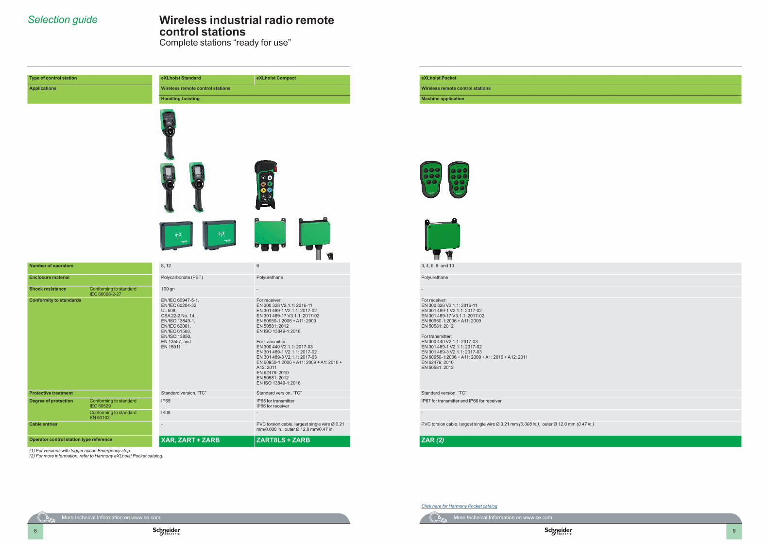
Type of control station eXLhoist Standard eXLhoist Compact eXLhoist Pocket
Applications Wireless remote control stations Wireless remote control stations
Handling-hoisting Machine application
Number of operators 8, 12 6 3, 4, 6, 8, and 10
Enclosure material Polycarbonate (PBT) Polyurethane Polyurethane
Shock resistance Conforming to standard IEC 60068-2-27
100 gn - -
Conformity to standards EN/IEC 60947-5-1,EN/IEC 60204-32,UL 508,CSA 22-2 No. 14,EN/ISO 13849-1, EN/IEC 62061,EN/IEC 61508,EN/ISO 13850,EN 13557, andEN 15011
For receiver: EN 300 328 V2.1.1: 2016-11 EN 301 489-1 V2.1.1: 2017-02 EN 301 489-17 V3.1.1: 2017-02 EN 60950-1:2006 + A11: 2009 EN 50581: 2012 EN ISO 13849-1:2016
For transmitter: EN 300 440 V2.1.1: 2017-03 EN 301 489-1 V2.1.1: 2017-02 EN 301 489-3 V2.1.1: 2017-03 EN 60950-1:2006 + A11: 2009 + A1: 2010 + A12: 2011 EN 62479: 2010 EN 50581: 2012 EN ISO 13849-1:2016
For receiver:EN 300 328 V2.1.1: 2016-11EN 301 489-1 V2.1.1: 2017-02EN 301 489-17 V3.1.1: 2017-02EN 60950-1:2006 + A11: 2009EN 50581: 2012
For transmitter:EN 300 440 V2.1.1: 2017-03EN 301 489-1 V2.1.1: 2017-02EN 301 489-3 V2.1.1: 2017-03EN 60950-1:2006 + A11: 2009 + A1: 2010 + A12: 2011EN 62479: 2010EN 50581: 2012
Protective treatment Standard version, “TC” Standard version, “TC” Standard version, “TC”
Degree of protection Conforming to standard IEC 60529
IP65 IP65 for transmitterIP66 for receiver
IP67 for transmitter and IP66 for receiver
Conforming to standard EN 50102
IK08 - -
Cable entries - PVC torsion cable, largest single wire Ø 0.21 mm/0.008 in., outer Ø 12.0 mm/0.47 in.
PVC torsion cable, largest single wire Ø 0.21 mm (0.008 in.), outer Ø 12.0 mm (0.47 in.)
Operator control station type reference XAR, ZART + ZARB ZART8LS + ZARB ZAR (2)(1) For versions with trigger action Emergency stop.(2) For more information, refer to Harmony eXLhoist Pocket catalog.
Click here for Harmony Pocket catalog
98
Wireless industrial radio remote control stations Complete stations “ready for use”
Selection guide
10
Presentation Harmony eXLhoist 4 Wireless industrial radio remote control
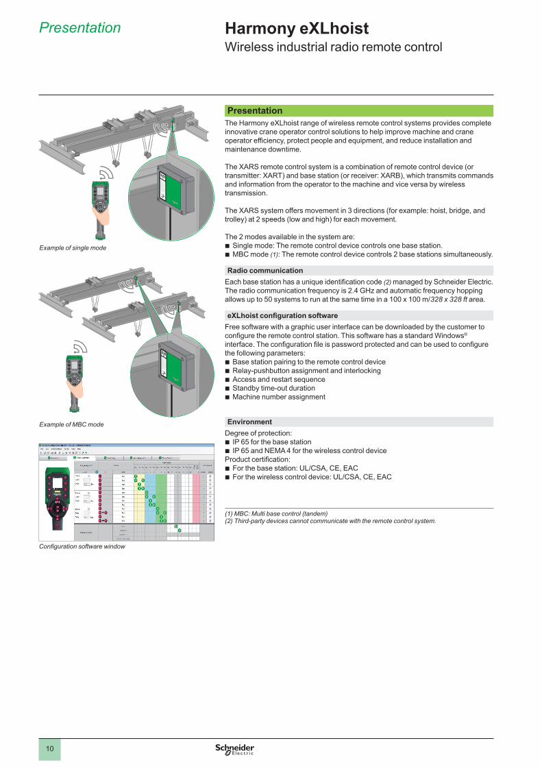
PresentationThe Harmony eXLhoist range of wireless remote control systems provides complete innovative crane operator control solutions to help improve machine and crane operator efficiency, protect people and equipment, and reduce installation and maintenance downtime.
The XARS remote control system is a combination of remote control device (or transmitter: XART) and base station (or receiver: XARB), which transmits commands and information from the operator to the machine and vice versa by wireless transmission.
The XARS system offers movement in 3 directions (for example: hoist, bridge, and trolley) at 2 speeds (low and high) for each movement.
The 2 modes available in the system are: b Single mode: The remote control device controls one base station.b MBC mode (1): The remote control device controls 2 base stations simultaneously.
Radio communication Each base station has a unique identification code (2) managed by Schneider Electric. The radio communication frequency is 2.4 GHz and automatic frequency hopping allows up to 50 systems to run at the same time in a 100 x 100 m/328 x 328 ft area.
eXLhoist configuration software Free software with a graphic user interface can be downloaded by the customer to configure the remote control station. This software has a standard Windows® interface. The configuration file is password protected and can be used to configure the following parameters:b Base station pairing to the remote control deviceb Relay-pushbutton assignment and interlockingb Access and restart sequenceb Standby time-out durationb Machine number assignment
EnvironmentDegree of protection:b IP 65 for the base stationb IP 65 and NEMA 4 for the wireless control deviceProduct certification:b For the base station: UL/CSA, CE, EACb For the wireless control device: UL/CSA, CE, EAC
(1) MBC: Multi base control (tandem)(2) Third-party devices cannot communicate with the remote control system.
Configuration software window
Example of single mode
Example of MBC mode

11
Harmony eXLhoist 4 Wireless industrial radio remote control Harmony eXLhoist Standard
Description 4
DescriptionRemote control device
The remote control device has the following controls:1-6 Auxiliary buttons (for ZART8D and ZART8L only
buttons 5 and 6 are available)7 Display (for ZART8L LED display only)8 E-stop LED9 OFF/Stop button10 ON/Start/Horn button11 Motion buttons12 Cover 13 RJ45 connector14 Reset button15 Trigger button16 Connector for charging remote device17 Connector cover18 E-stop button
Base stationThe base station has the following controls:1 M12 for external antenna (1)2 Status LEDs3 M20 for the Safeguarding function input wires (1)4 62-pin connector (1)5 M25 for output wires (2)6 M25 for detected application alarm input wires (1)7 4 holes for standard mounting on support (1)
(1) Covered by an end cap(2) Covered by a cable gland
Front view of ZART12D remote device
2746810
1359
11
Underside view of remote device handle
161718
Rear view of remote device
12
15
1413
Underside view of ZARBpH base station
4 3 2 1
Underside view of ZARBpW base station
6 5 3 2 1
Front view of base station with cover
ZAR
BpW
ZAR
BpH
7 7
12
Harmony eXLhoist 4 Wireless industrial radio remote control Harmony eXLhoist Compact
Description 4
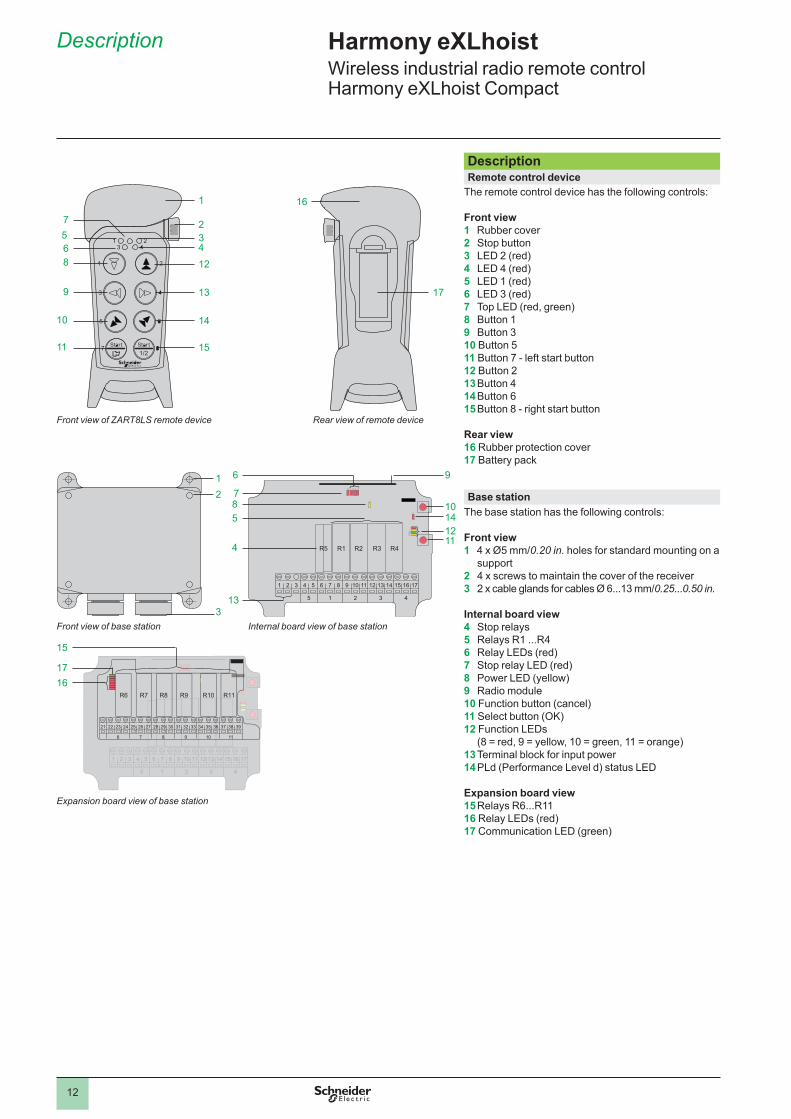
DescriptionRemote control device
The remote control device has the following controls:
Front view1 Rubber cover2 Stop button3 LED 2 (red)4 LED 4 (red)5 LED 1 (red)6 LED 3 (red)7 Top LED (red, green)8 Button 19 Button 310 Button 511 Button 7 - left start button12 Button 213 Button 414 Button 615 Button 8 - right start button
Rear view16 Rubber protection cover17 Battery pack
Base stationThe base station has the following controls:
Front view1 4 x Ø5 mm/0.20 in. holes for standard mounting on a
support2 4 x screws to maintain the cover of the receiver3 2 x cable glands for cables Ø 6...13 mm/0.25...0.50 in.
Internal board view 4 Stop relays5 Relays R1 ...R46 Relay LEDs (red)7 Stop relay LED (red)8 Power LED (yellow)9 Radio module10 Function button (cancel)11 Select button (OK)12 Function LEDs
(8 = red, 9 = yellow, 10 = green, 11 = orange)13 Terminal block for input power14 PLd (Performance Level d) status LED
Expansion board view 15 Relays R6...R1116 Relay LEDs (red)17 Communication LED (green)
R1 R2 R4R3
43215
1716151413121110987654321
R5
710
6 9
141211
85
4
13
1617
15
43215
1716151413121110987654321
R10 R11R9R6 R7 R8
11109876
39383736353433323130292827262524232221
12
3
2
12
13
14
1511
10
9
86
75
43
1
17
16
Front view of ZART8LS remote device
Front view of base station Internal board view of base station
Expansion board view of base station
Rear view of remote device

13
References 4
Remote control deviceDescription Characteristics Reference Weight
kg/lbMotion pushbuttons
Auxiliary pushbuttons
Standard MBC (1)
Harmony eXLhoist StandardWith LEDs
6 2 ZART8L ZART8LM (slave)
0.650/1.433
With display
6 2 ZART8D ZART8DM (master or slave)
0.650/1.433
With display
6 6 ZART12D ZART12DM (master or slave)
0.650/1.433
Harmony eXLhoist CompactWith LEDs
6 1 ZART8LS - 0.300/0.661
Base stationDescription Characteristics Reference Weight
kg/lbOutputs Inputs Power supply V
Standard MBC (1)
Harmony eXLhoist StandardWired connection cable gland
12 relays + 2 safety relays
- 24...240 z ZARB12W - 1.450/3.197
Industrial plug connection
12 relays + 2 safety relays
- 24...48 z ZARB12H - 1.450/3.197
Wired connection cable gland
18 relays + 2 safety relays
18 digital (12 limiters + 6 alarms)
24...240 z ZARB18W ZARB18WM 1.450/3.197
Industrial plug connection
18 relays + 2 safety relays
18 digital(12 limiters + 6 alarms)
24...48 z ZARB18H ZARB18HM 1.450/3.197
Harmony eXLhoist CompactWired connection cable gland
10 relays + 2 safety relays
- 48...240 a ZARB10WS - 0.430/0.947
Wired connection (pre-wired with 1.5 m/ 4 .92 ft cable)
10 relays + 2 safety relays
- 48...240 a ZARB10WSP - 0.880/1.940
Wired connection (pre-wired with 1.5 m/ 4 .92 ft cable)
10 relays + 2 safety relays
- 12...24 z ZARB10WSPDC- 0.880/1.940
Wireless remote control systemDescription Characteristics Reference Weight
kg/lbSpecial functions
Connection
Complete unit (without charger device)
- Wiring XARS8L12W(ZART8L + ZARB12W)
2.100/4.640
- Industrial plug
XARS8L12H(ZART8L + ZARB12H)
2.100/4.640
Limiter protectionMovement monitoring
Wiring XARS8D18W(ZART8D + ZARB18W)
2.100/4.640
Industrial plug
XARS8D18H(ZART8D + ZARB18H)
2.100/4.640
Wiring XARS12D18W(ZART12D + ZARB18W)
2.100/4.640
Industrial plug
XARS12D18H(ZART12D + ZARB18H)
2.100/4.640
(1) MBC: Multi base control (tandem)
Harmony eXLhoist 4 Wireless industrial radio remote control Remote control device, base station, and wireless remote control system
ZARB12H ZARB18W
XARS12D18H
ZART8L
ZART8LS
ZARB10WS
ZARB10WSPDC
ZART8D
PF12
2406
A-32
-QXA
R_6
2193
_CPS
CT1
7001
BPF
1224
10A-
32-Q
XAR
_621
93_C
PSC
T170
15
PF12
2439
A-32
-Q
PF12
2408
A-32
-Q
XAR
_621
93_C
PSC
T170
03C
PF12
2411
A-32
-QPF
1224
07A-
32-Q
14
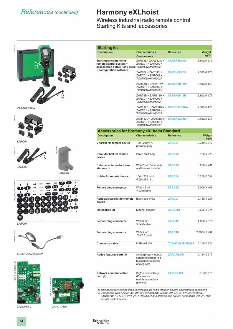
Starting kitDescription Characteristics Reference Weight
kg/lb Components
References (continued) 4 Harmony eXLhoist 4 Wireless industrial radio remote control Starting Kits and accessories
XARSK8D18W
Starting kit comprising remote control system + accessories + USB/RJ45 cable + configuration software
ZART8L + ZARB12W + ZARC01 + ZARC02 + TCSMCNAM3M002P
XARSK8L12W 2.800/6.173
ZART8L + ZARB12H + ZARC01 + ZARC02 + TCSMCNAM3M002P
XARSK8L12H 2.800/6.173
ZART8D + ZARB18W + ZARC01 + ZARC02 + TCSMCNAM3M002P
XARSK8D18W 2.800/6.173
ZART8D + ZARB18H + ZARC01 + ZARC02 + TCSMCNAM3M002P
XARSK8D18H 2.800/6.173
ZART12D + ZARB18W + ZARC01 + ZARC02 + TCSMCNAM3M002P
XARSK12D18W 2.800/6.173
ZART12D + ZARB18H + ZARC01 + ZARC02 + TCSMCNAM3M002P
XARSK12D18H 2.800/6.173
Accessories for Harmony eXLhoist StandardDescription Characteristics Reference Weight
kg/lbCharger for remote device 100...240 V a
power supplyZARC01 0.350/0.772
Shoulder belt for remote device
2 m/6.56 ft long ZARC02 0.100/0.220
External antenna for base station (1)
With 2 m/6.56 ft cable and bracket included
ZARC03 0.200/0.441
Holder for remote device 104 x 239 mm/ 4.09 x 9.41 in.
ZARC04 0.250/0.551
Female plug connector With 1.5 m/ 4.92 ft cable
ZARC05 2.000/4.409
Adhesive label kit for remote device
Black and white ZARC07 0.150/0.331
Installation kit Magnet support ZARC091 0.625/1.375
Female plug connector With 3 m/ 9.84 ft cable
ZARC12 4.000/8.818
Female plug connector With 5 m/ 16.40 ft cable
ZARC18 7.000/15.432
Connector cable USB to RJ45 TCSMCNAM3M002P 0.100/0.220
Added features card (2) Analog input modbus serial line card (Field bus communication analog card)
ZARCFBA01 0.144/0.317
Network communication card (2)
Sigfox connectivity (Preventive maintenance data gateway)
ZARCIOT01 0.05/0.110
(1) This accessory can be used to increase the radio range in severe environment conditions.(2) Compatible with XARS12D18W, XARSK8D18W, ZARB12W, ZARB18W, ZARB18WM,
ZARB12WR, ZARB18WR, ZARB18WRM base stations and are not compatible with ZART8L remote control device.
ZARCFBA01 ZARCIOT01
PF12
2426
XAR
_621
93_C
PDPM
1800
1
XAR
_621
93_C
PDPM
1800
2
ZARC01
PF12
2413
ZARC02
PF12
2414
ZARC04
DF5
1432
4
ZARC07
XAR
_621
93_C
POD
A201
6005
TCSMCNAM3M002P
\PF5
1433
7-68
-Q

15
Accessories for Harmony eXLhoist CompactDescription Characteristics Reference Weight
kg/lbMulti-charger power supply 6W, 5 V c /1.2 A (for ZARC702 Li-Ion rechargeable battery only)
100...240V a power supply
ZARC701 0.100/0.220
Li-Ion rechargeable battery with battery table charger
83 x 46 mm/ 3.268 x 1.811 in.
ZARC702 0.050/0.110
Battery pack for 3 x AAA (batteries not included)
83 x 46 mm/ 3.268 x 1.811 in.
ZARC704 0.020/0.044
Battery table charger,(for ZARC702 Li-Ion rechargeable battery only)
5 V c power supply
ZARC703 0.120/0.265
Front label cover for ZART8LS pushbuttons
120 x 60 mm/ 4.724 x 2.362 in.
ZARC705 0.005/0.011
Rubber protection cover for ZART8LS
Rubber material, black ZARC706 0.107/0.24
Shoulder belt to support ZART8LS
Nylon material, black ZARC707 0.130/0.29
Harmony eXLhoist 4 Wireless industrial radio remote control Accessories
References (continued) 4
ZARC701
ZARC702 ZARC703
ZARC706 ZARC707
ZARC705
XAR
_621
93_C
PSC
T170
04XA
R_6
2193
_CPS
CT1
7005
XAR
_621
93_C
PSC
T170
06
XAR
_621
93_C
PSC
T170
08B
XAR
_621
93_C
PSC
T170
09
XAR
_621
93_C
PSC
T170
10
16
Product reference indexIndex
TTCSMCNAM3M002P 14X
XARS12D18H 13XARS12D18W 13XARS8D18H 13XARS8D18W 13XARS8L12H 13XARS8L12W 13XARSK12D18H 14XARSK12D18W 14XARSK8D18H 14XARSK8D18W 14XARSK8L12H 14XARSK8L12W 14Z
ZARB10WS 13ZARB10WSP 13ZARB10WSPDC 13ZARB12H 13ZARB12W 13ZARB18H 13ZARB18HM 13ZARB18W 13ZARB18WM 13ZARC01 14ZARC02 14ZARC03 14ZARC04 14ZARC05 14ZARC07 14ZARC091 14ZARC12 14ZARC18 14ZARC701 15ZARC702 15ZARC703 15ZARC704 15ZARC705 15ZARC706 15ZARC707 15ZARCFBA01 14ZARCIOT01 14ZART12D 13ZART12DM 13ZART8D 13ZART8DM 13ZART8L 13ZART8LM 13ZART8LS 13

The information provided in this documentation contains general descriptions and/or technical characteristics of the performance of the products contained herein. This documentation is not intended as a substitute for and is not to be used for determining suitability or reliability of these products for specific user applications. It is the duty of any such user or integrator to perform the appropriate and complete risk analysis, evaluation and testing of the products with respect to the relevant specific application or use thereof. Neither Schneider Electric nor any of its affiliates or subsidiaries shall be responsible or liable for misuse of the information contained herein.
Design: Schneider ElectricPhotos: Schneider Electric
Learn more about our products at www.se.com/harmony-exlhoist
DIA5ED2140103ENApril 2021 - V6.0
Schneider Electric Industries SASHead Office35, rue Joseph Monier - CS 30323F-92500 Rueil-Malmaison CedexFrance