Embed Size (px)
Citation preview

NASA-CR-192953
GENE_IC HYPERSONIC VEHICLE....... PERFORMANCE MODEL
Interim Task Renort
O
o
- for
_ NASA Grant NAG-I-1341
= On Research Performed for the
=
__ ____--= _
NASA LangleyResearch Center
Hampton, VA
estlgaPrifi/:ipal lnv tors
k R. Chavez and Dr. David K. Sch_dt
Aerospace Research center
Sciences
||
4
- 1m _ii
!i ma CI o
J N
! w'?.J u<_I z,.-
J _C_b.
U,s aC _.
UJ_ c_
tl
d W_ e'_
L_) LtJ Uj 4._
ge of Engineering and AppliedArizonaStateUniversity
Tempe, AZ 85287-8006
Internal Report No. ARC93-3
__ April 1993
li
I
https://ntrs.nasa.gov/search.jsp?R=19930015973 2018-06-15T10:16:46+00:00Z

w
W
W
m
o
i
J
i,t
_e
wTABLE OF CONTENTS
SECTION PAGE
w t
w
w
N
w
L
= =
L_
w
r_w
H
w
w
mqlW
tJ
I
m
w
II
III
IV
V
INTRODUCTION ................................................................................................... 1
AERODYNAMIC ANALYSIS ............................................................................. 2
Compression Surface .......................................................................................... 2
Control Surface ................................................................................................... 2
Expansion Surface .............................................................................................. 3
Skin-friction Drag ............................................................................................... 3
The Total Aerodynamic Force and Moment ...................................................... 3
ENGINE ANALYSIS ............................................................................................. 5
Engine Inlet ......................................................................................................... 5
Engine Diffuser ................................................................................................... 6
Engine Combustor .............................................................................................. 6
Engine Expansion Nozzle ................................................................................... 7
The Total Engine Force and Moment ............................................................... 7
EXHAUST PLUME ANALYSIS ........................................................................... 9
Plume Position and Pressure Calculation ........................................................... 9
The Total Exhaust Gas Force and Moment ....................................................... I0
MATLAB ® PROGRAM DESCRIPTION ............................................................ 12
Program Flow Chart ........................................................................................... 12
Program NASPmain ........................................................................................... 14
Subroutine MODCP ........................................................................................... 16
Subroutine AEROBODY .................................................................................... 17
S ubroutine AEROCNSF ..................................................................................... 17
Subroutine ENGINE ........................................................................................... 18
Subroutine PLUME ............................................................................................ 20
Subroutine DIFFUSER ....................................................................................... 21
Subroutine COMBUSTOR ................................................................................. 21
Subroutine NOZZLE .......................................................................................... 22
Subroutine GTAD ............................................................................................... 22
mw

SECTION PAGE
Subroutine GTTO ............................................................................................... 23
Subroutine REORDR .......................................................................................... 23
Subroutine GTNORML ...................................................................................... 23
mm
I
-____g
VI INPUT/OUTPUT EXAMPLE ................................................................................ 25
Sample NASPinput File ...................................................................................... 25
Sample Output File ............................................................................................ 27
I
m
VII REFERENCES ....................................................................................................... 28!
!1
m
m
i
I
I
m
m
i
ii
g
-S.. _
m
g

FIGURE
LIST OF FIGURES
PAGE
o
2.
3.
4.
5.
Vehicle Geometry ................................................................................................ 4
Control Surface Geometry ................................................................................... 4
Engine Station Locations ..................................................................................... 8
Engine Inlet Velocity Vector Diagram ................................................................ 8
Plume Shape Calculation Coordinate System .................................................... 11
L
=
r_
W
H
w
N
m
U
I$
!
m
_mm
g
RI
I
m
I
_m
g
W
i
m
w
I
u
_g
I
g
l
II
ii
J
U
m

I_RODUCTION
W
w
W
r.=_=_IEi
2--
t_
U
rma
tmW
!
ID
U
An integrated computational model of a generic hypersonic vehicle has been
developed for the purpose of determining the vehicle's performance characteristics, which
include the Lift, Drag, Thrust, and Moment acting on the vehicle at specified altitude, flight
condition, and vehicular configuration. The material presented herein is based on the prior
work reported in [1]. The Lift, Drag, Thrust, and Moment are developed for the body fixed
coordinate system. These forces and moments arise from both aerodynamic and propulsive
sources. SCRAMjet engine performance characteristics, such as fuel flow rate, can also be
determined.
The vehicle is assumed to be a lifting body with a single aerodynamic control surface.
The body shape and control surface location are arbitrary and must be defined.
The aerodynamics are calculated using either 2-Dimensional Newtonian or Modified
Newtonian theory and approximate high-Mach-number Prandtl-Meyer expansion theory.
Skin-friction drag has also been accounted for. The skin-friction drag coefficient is a
function of the freestream Mach number. The data for the skin-friction drag coefficient
values were taken from NASA Technical Memorandum 102610 [2].
The modeling of the vehicle's SCRAMjet engine is based on quasi 1-Dimensional
gasdynamics for the engine diffuser, nozzle, and the combustor with heat addition. The
engine has three variable inputs for control. These are the engine inlet diffuser area ratio, the
total temperature rise through the combustor due to combustion of the fuel, and the engine
internal expansion nozzle area ratio.
The pressure distribution over the vehicle's lower aftbody surface, which acts as an
external nozzle, is calculated using a combination of quasi 1-Dimensional gasdynamic theory
and Newtonian or Modified Newtonian theory. The exhaust plume shape is determined by
matching the pressure inside the plume, calculated from the gasdynamic equations, with the
freestream pressure, calculated from Newtonian or Modified Newtonian theory. In this
manner, the pressure distribution along the vehicle afterbody expansion surface is then
determined.
The following three sections describe the aerodynamic modeling, the engine
modeling, and the exhaust plume analysis in more detail. Section four gives a description of
the computer code used to perform the above calculations, and an input/output example is
then given in section five. The computer code is available on a Macintosh floppy disk.
[]
U

w
AERODYNAMIC ANALYSIS m
Compression Surface
The non-dimensional pressure coefficient as given by Modified Newtonian theory is
given below as [3]
Cpcom(7, M.., 0 ) -2
y M_ 2 [ (7+1)2 M**24 T M.2 -2 (y-l)
7
_[ 2 Y M_*2 - (7-1)-y+l - 11 sin2(O) (1)
where 0 is the local flow deflection angle defined as
0 = ot + "_ (2)
The angles ot and x are, respectively, the angle of attack and the local surface slope relative
to the body fixed axis as shown in Fig 1. For Newtonian theory, the pressure coefficient
value is given by Cpcom(T,M.., 0) = 2.0 sin2(0). The compression surface is divided into
sections or panels each of which has a constant value for % say "q. The pressure coefficient
on the corresponding panel is then given as
Cpi = Cpcom(7, M_,, 0i) (3)
where 0i = (z + zi. The force per unit width acting on the ith panel is given by
F_= -P** (1+ 1 _/M**2 Cpi) dsi ni (4)
where dsi is the area per unit width of the ith panel and _i is a unit vector normal to the ith
panel pointing outward, also shown in Fig 1. The moment per unit width acting about the
vehicle's center of mass is given by
fii = ;i X F-'i (5)
where _i is the vector from the vehicle's mass center to the centroid of the ith panel.
Control Surface
The force per unit width acting on the control surface is given by
F'-'cs= P** [1+ 2y M**2 Cpcom(y,M**,0¢s) ]Scs _s (6)
where 0cs = o_ + 5, and 8 is the control surface deflection, Scs is the control surface area per
unit width, and ncs is a unit vector normal to the control surface as shown in Fig 2. The
moment per unit width acting about the vehicle's mass center is given by-.,#
Mcs = _cs x Fcs (7)
where _cs is a vector from the vehicle's mass center to the center of the control surface, which
is where the aerodynamic center of the control surface is assumed to be located.
m
m
J
Ill
m
mm
I
I
J
III
lip
i
g
J
m
Ill
qll
W
2m
__4
m

=
U
r==
L3
Expansion Surface
The pressure coefficient as given by the approximate high Mach number Prandtl-
Meyer expansion theory is [4]
Cpexp(7, M_., a ) = ._._2___7 M_. 2
where tx is the angle of attack.
is given by
-7
y-11+ (7-1__)M**22 - 1 (8)
(y-l) M_ 21+ 2
[1- (T-I) O_M_l 22
With this, the force per unit width acting on the upper surface
Fus =- P [1+ 1 It M,,.2 Cpexp(qr, M**, o0]Lu _u (9)
where Lu is the area per unit width of the vehicle's upper surface and _u is a unit vector
normal to the upper surface pointing outward as shown in Fig 1. The moment per unit width
acting about the vehicle's mass center is given by
flus=_us x F_ (10)
where _us is a vector from the vehicle's mass center to the center of the vehicle's upper
surface.
=
=_
L_
w
w
w
im
U
Skin-Friction Drag
The skin-friction drag term is given as
Dsf = q** Cdo(M**) Sref (1 l)
where qoo is the freestream dynamic pressure. The data used for Cdo(M**) and Sref were
obtained from NASA Technical Memorandum 102610 "Hypersonic Vehicle Simulation:
Winged Cone Configuration" [2]. This drag term is in the velocity fixed coordinate system.
In the body fixed coordinate system, the lift and drag terms are as follows
Lo = Dsf sin(or) (12)
Do = Dsf cos(tx) (13)
The Total Aerodynamic Force and Moment
The total aerodynamic force and moment per unit width is determined by adding all
the separate contributioris from the compression surface panels, the control surface, the upper
surface, and the skin-friction drag.
FA = _ Fi + Fus + Fcs - (Do i + Lo (14)i
i

An
control surface
ZB
g
m
J
m
Figure 1. Vehicle Geometry
Control Surface
Figure 2. Control Surface Geometry
u
W
m
!W
m
m
W
w
IIw
4
m
qll
=
¢amaENGINE ANALYSIS
=
z :
W
!
v
u
D
m
w
w
t
m
iw
im
m
J
!
Ig
I
!¢
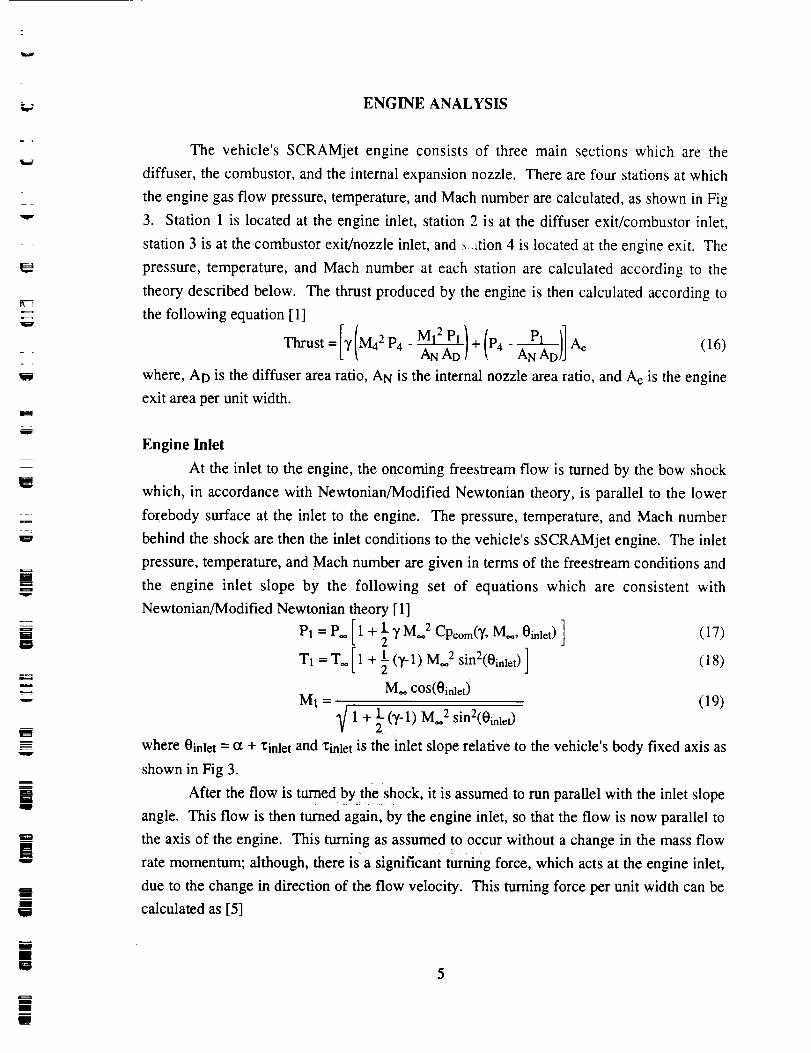
The vehicle's SCRAMjet engine consists of three main sections which are the
diffuser, the combustor, and the internal expansion nozzle. There are four stations at which
the engine gas flow pressure, temperature, and Mach number are calculated, as shown in Fig
3. Station 1 is located at the engine inlet, station 2 is at the diffuser exit/combustor inlet,
station 3 is at the combustor exit/nozzle inlet, and __ztion 4 is located at the engine exit. The
pressure, temperature, and Mach number at each station are calculated according to the
theory described below. The thrust produced by the engine is then calculated according to
the following equation [ 1]
= p___h_Thrust [)r(M4 2P4-M12P_/+ANAD/(P4-ANAD)]Ae (16)
where, AD is the diffuser area ratio, AN is the internal nozzle area ratio, and A e is the engine
exit area per unit width.
Engine Inlet
At the inlet to the engine, the oncoming freestream flow is turned by the bow shock
which, in accordance with Newtonian/Modified Newtonian theory, is parallel to the lower
forebody surface at the inlet to the engine. The pressure, temperature, and Mach number
behind the shock are then the inlet conditions to the vehicle's sSCRAMjet engine. The inlet
pressure, temperature, and Mach number are given in terms of the freestream conditions and
the engine inlet slope by the following set of equations which are consistent with
Newtonian/Modified Newtonian theory [1]
P1 = P_ [1+ 2y M**2 Cpcom(Y, M**, 0inlet)] (17)
T1 = T.[I+ 1 (y-l)M** 2 sin2(0inlet) ] (18)
M** cos(0inlet)
M1 = (19)
V 1 + 21-(y-l) M**2 sin2(0inlet)
where 0inlet = _ + 1;inlet and "l:inlet is the inlet slope relative to the vehicle's body fixed axis as
shown in Fig 3.
After the flow is turned by theshock, it is assumed to run parallel with the inlet slope
angle. This flow is then turned again, by the engine inlet, so that the flow is now parallel to
the axis of the engine. This turning as assumed to occur without a change in the mass flow, = : ::: :
rate momentum; although, there is a significant turning force, which acts at the engine inlet,
due to the change in direction of the flow velocity. This turning force per unit width can be
calculated as [5]
5

W
F-inlet = 7 M12 Pl [(1- cos0inlet ) i + (sin0inlet) k] Ae (20)AD AN
which can be seen from the vector diagram in Fig 4. Again, it is noted that this turning force
is due solely to the change in the flow velocity direction as it turns into the engine. The
moment per unit width acting about the vehicle mass center due to this turning force is given
by
Minlet = _mlet x F"*mlet (21)
where _inlet is the vector from the vehicle mass center to the engine inlet.
_I
U
Ill
g
uI
Engine Diffuser
The gasdynamic equations which relate the diffuser exit conditions to the diffuser
inlet conditions are given by [4]
(1 + 1 (_'-1) M22_ -_ _ AD 2 {1 +1_. (7-1) M12_ -_ (22)
M2 2 M12
[l+lP2 = P1 _- (y-l) M12 _ (23)
1 + 2 (y-l) M22J
1 + l(y-1) MI 2]T2 = T1 2
1 + 2_(Y-1)MzzJ (24)
The inlet conditions to the diffuser are simply the inlet conditions to the engine given by
Eqns (17), (18), and (19).
m.!
g
W
iJ
i
m
u
Engine Combustor
The gasdynamic equations which relate the combustor exit conditions to the
combustor inlet conditions are given by [4]
M32[ l + 1 (Y'I)M32] = M22[ 1 + 1 (3t-l)M22] + M22 To (25)
(yM32 + 1) 2 (yM22 + i) 2 (yM22 + 1)2 T2
P3=P2[I+yM221+yM32j (26)
T3=T2 ([_1+ Y M22) ME] 2+ 2' M32) (27)
The inlet conditions to the combustor are simply the exit conditions from the diffuser, which
are given by Eqns (22), (23), and (24). The quantity To, which denotes the total temperature
rise across the combustor due to combustion of the fuel, is related to the mass flow rate of
fuel by the following equation [6]
=_____
g
W
nB
g
m
D
m
m

5
W
L_
w
W
m
m
W
m_ir I qc._._Q.Q
L _ m_r IJ
where rhfuel is the mass flow rate of fuel to the engine, ri'lai r is the mass flow rate of air
through the engine, rio is the combustion efficiency, Q is the heating value of the fuel, and Cp
is the specif'c heat at constant pressure for the fuel/air mixture.
In the above equation for M3; i.e., Eqn (25), it is important to note that M3 is
essentially a function of diffuser area ratio, AD, and total temperature rise, To. For given
values of AD and To, the exit Mach number, M3, must remain above M3 = 1; i.e., the flow
must not be choked.
Engine Internal Expansion Nozzle
The gasdynamic equations which relate the nozzle exit conditions to the nozzle inlet
conditions are given by [4]
2 (29)
M42 M32
P4 = P3 (30)
1+ M42J
T4 = T3 1 (31)
+ 1)
The inlet conditions to the nozzle are simply the exit conditions from the combustor which
are given by Eqns (25), (26), and (27). These nozzle exit conditions are also the engine exit
conditions which are used in Eqn (16), along with the engine inlet conditions given by Eqns
(17), (18), and (19), to determine the thrust produced by the engine.
m
m
!qP
g
Eg
N
m
The Total Engine Force and Moment
With the thrust given by Eqn (16), the thrust force per unit width is given as
FTh = Thrust i (32)
The moment per unit width acting about the vehicle mass center is given byA
MTh = (zinl_t Thrust)j (33)
where Zinlet is the distance from the mass center to the centerline of the engine, which is
assumed to be parallel with the vehicle's body fixed x-axis.
The total engine force and moment per unit width is then given by the sum of the
separate contributions as
7

= FTh + Finlet
ME = MTh + Minlet
(34)
(35)
u
i
I I© ®
CombustorInternal Nozzle
®Figure 3. Engine Station Locations
....)
V2
--4
Z B
X B
Figure 4. Engine Inlet Velocity Vector Diagram
=_
J
g
m
m
m
m
W
i
I
m
D
m
m
HI
1me
w
m
w

EXHAUST PLUME ANALYSIS
m
5
gV
!lt
m
qg_
i
llp
[]
MW
!t_g
[]
Plume Position and Pressure Calculation
In Fig 5, the geometry used to perform the plume shape calculation is shown. The
region enclosed by the vehicle's lower aftbody expansion surface and the plume surface is
discretized into several sections. The plume shape is assumed to have a quadratic form along
each of these sections given by
Yi = ai + bi (x - Xi_l) + Ci (X - Xi_l) 2 (36)
The slope of the plume shape, denoted as 13i, is then simply given by the derivative of Eqn
(36)
tan(_i) = bi + 2 ci (x- xi.1) (37)
The Mach number and pressure at station (i) is given in terms of the Mach number and
pressure at station (i-1) through the gasdynamic equations for an expansion [4]
(1+ 1 Mi_12_-iL(1 + _-(T-l)Mi2_ -_ (AD)i2 2- (T"I)= (38)Mi 2 Mi_l 2
f 1 +2(T -1) Mi-12:
(Pi)inner=(Pi_l)inner L 1+} (T'I) Mi2 J (39)
The area ratio for section (i) is given by
(AD)i = yi(xi)- Si (40)yi(xi-1) - si-1
where si is the position of the vehicle's lower aftbody surface at station (i). The pressure
given by Eqn (39) is the pressure on the inside of the plume at station (i). The pressure on
the outside of the plume at station (i) is given by Newtonian/Modified Newtonian theory as
(Pi)outer = P. [1 + 1 T M,2 Cpcom(T, M., 0i) ] (41)
where 0i = a + 13i.
The plume shape at each section has three coefficients to be determined, ai, bi, and ci.
Two of the coefficients, ai and bi, can be determined by enforcing that the plume position and
slope at each station is continuous; i.e.,
yi(xi.1) = ai = Yi-l(Xi-1)
-_(xi-t) = bi = _xi-1)
(42)
(43)
The coefficient ci is determined by imposing the condition that the inner pressure value
determined from Eqn (39) and the outer pressure determined from Eqn (41) are equal. An
iterative approach is used to determine the proper value of ci at each station.
9

The solution procedure begins at the engine exit, where the plume position and the
pressure are known. The initial values for al and bl are given by
m
mw
al = 1 (44) m
It ]bl tan sin "1 P**= - a (45)1
y M**- Cpcom(7, M.., 2 )
The solution at each station is then determined successively using the solution obtained at the
previous station.
The Total Exhaust Gas Force and Moment
With the pressure at each station now known from the above procedure, the force per
unit width acting on each panel of the vehicle's lower aftbody expansion surface can be
written as
Fi = - (Pi-1 + Pi) dsi ni (46)
where dsi is the area per unit width of the ith panel and _i is a unit vector normal to the ith
panel pointing outward. The moment per unit width acting about the vehicle mass center due
to the i th panel is given by
Mi = _i x Fi (47)
where _'i is a unit vector from the mass center to the centroid of the ith panel.
The total force and moment per unit width is then just the sum of the separate
contributions from each of the panels
Ex=r i (48)MEx = ]_Mi (49)
M
I
W
iiE
g
ID
i
m
g
m
g
i
i
m
: ,=
m
I
i
J
10
: =
z
J

L_
F_
L--
m
D
= .
C.G.
S i+l
Afterbody Expansion Surface
s./
Internal Nozzle I_e
_Plume Sha Je
v
x I
Figure 5. Plume Shape Calculation Coordinate Sysytem
M
W
li
i
U
liJ
W
11

MATLAB® PROGRAM DESCRIPTIONm
In this section, a program flow chart is given followed by a description of the
subroutines called by the main program, NASPmain. The program is written in MATLAB®.
The input file is named NASPinput and contains the information as shown in the example
case of the next section.
Program Flow Chart
NASPinput ]
NASPmain ]
-t I
g
m
I
g
g
m
w
il
g
AEROBODY
b
J
-t ooRI
GTNORML
I
z
=
I
12J

= :
vu_
w
m
g
IW
IW
AEROCNSF
ENGINE
_[ DIFFUSER
_[ COMBUSTOR
NOZZLE
GTAD
_1 GTFO
PLUME
REORDR
t GTNORML
13

=w
Program NASPmain
The inputs are:
given in the input file NASPinput
g
The outputs are:
any of the following variables described below
Variable names description:
Cpmax - Maximum pressure coefficient value determined from Newtonian
or Modified Newtonian Theory
gama - Ratio of specific heats, set to 1.43
dtr - Conversion factor for converting from degrees to radians
rtd - Conversion factor for converting from radians to degrees
R - Gas constant for air, set to 1686.0 [(lb ft)/(slug ° K)]
To - Total temperature rise across the combustor [° K]
Ad - Engine diffuser area ratio
Vi - Freestream velocity [ft/s]
Machi - Freestream Mach number
Ti - Freestream temperature [° K]
dynpres - Dynamic pressure [lb/ft 2]
Pi - Freestream pressure [lb/ft 2]
arotyp - Parameter used to determine type of 'Cpmax' calculation
arotyp = 0: Newtonian theory
arotyp = 1: Modified Newtonian theory
uspts - Array of two (x,z) data points defining the upper surface [ft]
lspts - Array of (x,z) data points defining the lower forebody compression
surface [ft]
alpha - Angle of attack [degrees]
Lb - Lift per unit width due to upper and lower compression
surface[lb/ft]
Db - Drag per unit width due to upper and lower compression
surface [lb/ft]
Mb - Moment per unit width about the mass center due to upper and
lower compression surface [lb]
delta - Control surface deflection, positive down [degrees]
Scs - Control surface area per unit width (includes both sides) [ft]
14
m
m
m
mm
iRm
ill
m
e
lI
m
li
III
m
m
J
I
2---
B
g
J

L
w
g
Vt=_
t_
[]t_mU
u
im
U
Ii
mmW
xcs
zCS
Lcs
Dcs
Mcs
Laero
Daero
Maero
inslp
xinlt
zinlt
ctyp
An
Ae
Leng
Teng
Meng
Engdat
exspts
Lex
Tex
Mex
plmpts
- x-axis location of the control surface [ft]
- z-axis location of the control surface [ft]
- Lift per unit width due to the control surface [lb/ft]
- Drag per unit width due to the control surface [lb/ft]
-Moment per unit width about the mass center due to the control
surface[lb]
- Total lift per unit width due to aerodynamics [lb/ft]
- Total drag per unit width due to aerodynamics [lb/ft]
- Total moment per unit width about the mass center due to
aerodynamics [lb/ft]
- Engine inlet angle [degrees]
- x-axis position of the engine inlet [ft]
- z-axis position of the engine inlet [ft]
- parameter used in ENGINE to set the type of engine control
ctyp = 0: calculate flow quantities based on given Ad and To
ctyp = 1: For the given To, Ad is calculated which will give a
choked flow condition at the combustor exit
ctyp = 2: For the given Ad, To is calculated which will give a
choked flow condition at the combustor exit
- Engine internal nozzle area ratio
- Engine exit area per unit width [ft]
- Lift per unit width due to the engine [Ib/ft]
- Thrust per unit width due to the engine [lb/ft]
- Moment per unit width about the mass center due to the engine [lb]
- Matrix containing the engine flow quantity values
Engdat = P1 [lb/ft 2] P2 [lb/ft 2] P3 [Ib/ft 2] P4 [lb/ft 2]
T1 [K] T2 [K] T3 [K] T4 [K]
M1 M2 M3 M4
- Array of (x,z) data points defining the lower aftbody expansion
surface [ft]
- Lift per unit width due to the exhaust gas [lb/ft]
- Thrust per unit width due to the exhaust gas [lb/ft]
- Moment per unit width about the mass center due to the exhaust
gas [lb]
- Array of (x,z) data points defining the calculated plume
position [ft]
15

W
Lift
Drag
Thrust
Momnt
igraph
scale
- Total lift per unit width on the vehicle [lb/ft]
- Total drag per unit width on the vehicle [lb/ft]
- Total thrust per unit width on the vehicle [Ib/ft]
- Total moment per unit width about the mass center on the
vehicle [lb]
- draws the vehicle and plume shape for igraph = 1
- sets the axis scale for the vehicle/plume diagram [ft]
The maximum value for the compression surface pressure coefficient is first
determined based on Newtonian or Modified Newtonian theory depending on the value of
'arotyp'. Next, the program calls AEROBODY, which calculates the lift, drag, and moment
values due to the vehicle's upper expansion surface, lower compression surface, and the skin-
friction drag, and AEROCNSF, which calculates the lift, drag, and moment values due to the
control surface, and then adds them to obtain the total aerodynamic contribution to the
vehicle's total lift, drag, and moment. Note that the 'uspts' array contains only two data points
which are the coordinates of the trailing edge and leading edge of the upper surface, which is
assumed to be parallel with the body fixed x-axis. The engine contribution to the total
vehicle lift, thrust, and moment are then calculated by calling ENGINE. Finally, PLUME is
called which calculates the lift, thrust, and moment due to the exhaust gas flow over the
vehicle's lower aftbody expansion surface. The plume shape is also calculated and returned
for graphing if desired. The total vehicle lift, drag, thrust, and moment is then calculated by
adding the separate contributions from the aerodynamics, engine, and exhaust gas flow.
Subroutine MODCP
The inputs are:
M - Freestream Mach number
g
g
i
mD
m
m
Hi
nm
i
mIn
NI
u
!
D
u
Mu
|
iII
The outputs are:
cpvalue - The maximum pressure coefficient value calculated from
Modified Newtonian theory
This subroutine calculates the maximum pressure coefficient value based on Modified
Newtonian theory which is the coefficient on the sin2(0) term in Eqn (1).
[]W
mtg
g
UW
16Ul
w

7
w
w
t
Subroutine AEROBODY
The inputs are:
uspts
lspts
Mi
Pi
qi
alpha
- Array of (x,z) data points defining the upper surface [ft]
- Array of (x,z) data points defining the lower forebody compression
surface [ft]
- Freestream Mach number
- Freestream pressure [lb/ft 2]
- Freestream dynamic pressure [lb/ft 2]
- Angle of attack [degrees]
The outputs are:
L
D
M
- Lift per unit width due to upper and lower compression
surface[lb/ft]
- Drag per unit width due to upper and lower compression
surface [Ib/ft]
- Moment per unit width about the mass center due to upper and
lower compression surface [Ib]
t:::l
m
[]w
M
EJ
m
m
n
J
W
The subroutine first determines if the upper surface is an expansion surface (o_ > 0) or
a compression surface (o_ < 0) and determines the upper surface pressure accordingly. The
two points defining the upper surface are then reordered, through a call to REORDR, so that
the GTNORML subroutine returns the correct direction for the upper surface unit normal
vector. The upper surface force and moment is then calculated according to Eqns (9) and
(10). The same procedure is followed for the lower compression surface panels. For each
panel, the unit normal vector is determined from which the panel force and moment are
calculated according to Eqns (4) and (5). The separate panel forces and moments are then
summed to obtain the total force and moment due the compression surface. Next, the skin-
friction drag coefficient is obtained for the particular freestream Mach number input. The
skin-friction drag force is then calculated and transformed from the velocity fixed coordinate
system to the body fixed coordinate system using Eqns (11), (12), and (13). The total lift and
drag is then determined from the components of the total force vector.
Subroutine AEROCNSF
The inputs are:
delta - Control surface deflection, positive down [degrees]
Scs - Control surface area per unit width (includes both sides) [ft]
17

xcs
zCS
Mi
Pi
qi
alpha
The outputs are:
L
D
M
- x-axis location of the control surface [ft]
- z-axis location of the control surface [ft]
- Freestream Mach number
- Freestream pressure [lb/ft 2]
- Dynamic pressure [lb/ft 2]
- Angle of attack [degrees]
- Lift per unit width due to the control surface [lb/ft]
- Drag per unit width due to the control surface [lb/ft]
-Moment per unit width about the mass center due to the control
surface[lb]
J
I
I
I
I
e
This subroutine calculates the lift, drag, and moment about the vehicle mass center
due to the control surface. The force acting on the control surface is first calculated in the
velocity fixed coordinate system. This force is then transformed to the body fixed coordinate
system depending on which side (upper or lower) of the control surface is exposed to the
oncoming freestream flow. The lift and drag are then determined from the components of the
force vector. The moment about the vehicle mass center is calculated according to Eqn (7).
m
m
D
Subroutine ENGINE
The inputs are:
alpha
inslp
xinlt
zinlt
Pi
Ti
Mi
ctyp
An
- Angle of attack [degrees]
- Engine inlet angle [degrees]
- x-axis position of the engine inlet [ft]
- z-axis position of the engine inlet [ft]
- Freestream pressure [lb/ft 2]
- Freestream temperature [° K]
- Freestream Mach number
- Parameter used in ENGINE to set the type of engine control
ctyp = 0: calculateflow quantities based on given Ad and To
ctyp = 1: For the given To, Ad is calculated which will give a
choked flow condition at the combustor exit
ctyp = 2: For the given Ad, To is calculated which will give a
choked flow condition at the combustor exit
- Engine nozzle area ratio
18
D
g
zg
g
m
l

vme - Engine exit area per unit width [ft]
F •
L_
2_d
L •
==
N
The outputs are:
L
T
My
data
- Lift per unit width due to the engine [Ib/ft]
- Thrust per unit width due to the engine [Ib/ft]
- Moment per unit width about the mass center due to the engine [lb]
- Matrix containing the engine flow quantity values
data = P1 [lb/ft 2] P2 [lb/ft 2] P3 [Ib/ft 2] P4 [lb/ft 2]
T1 [K] T2 [K] T3 [K] T4 [K]
M1 M2 M3 M4
P1 - Pressure at engine/diffuser inlet
T 1 - Temperature at engine/diffuser inlet
M1 - Mach no. at engine/diffuser inlet
P2 - Pressure at diffuser exit/combustor inlet
T2 - Temperature at diffuser exit/combustor inlet
M2 - Mach no. at diffuser exit/combustor inlet
P3 - Pressure at combustor exit/nozzle inlet
T3 - Temperature at combustor exit/nozzle inlet
M3 - Mach no. at combustor exit/nozzle inlet
P4 - Pressure at nozzle/engine exit
T4 - Temperature at nozzle/engine exit
M4 - Mach no. at nozzle/engine exit
The inlet conditions to the engine are first calculated using Eqns (17), (18), and (19).
Next, depending on the type of engine control; i.e. 'ctyp' value, the flow conditions across the
diffuser, combustor, and internal nozzle are calculated through calls to the subroutines
DIFFUSER, COMBUSTOR, NOZZLE, GTAD, and GTTO. The subroutines GTAD and
GTTO are called to determine the di_tiser_ea ratio, AD, or total temperature rise required,
To, to give a choked flow condition; i.e., M3 = 1.1, at the combustor exit. The values are
then stored in the matrix 'data'. The engine thrust and turning force are then determined using
Eqns (16) and (20) respectivley. The total moment about the vehicle's mass center is then
calculated from Eqn (35).
m
D
til19

Subroutine PLUME
The inputs are:
exspts
Pi
Mi
Engdat
me
alpha
- Array of (x,z) data points defining the lower aftbody expansion
surface [ft]
- Freestream pressure [lb/ft 2]
- Freestream Mach number
- Matrix containing the engine flow quantity values
Engdat -- P 1 [lb/ft 2] P2 [lb/ft 2] P3 [lb/ft 2]
T1 [K] T2 [K] T3 [K]
M1 M2 M3
- Engine exit area per unit width [ft]
- Angle of attack [degrees]
P4 [Ib/ft 2]
T4 [KI
M4
The outputs are:L
T
My
plmpts
- Lift per unit width due to the exhaust gas [lb/ft]
- Thrust per unit width due to the exhaust gas [lb/ft]
- Moment per unit width about the mass center due to the exhaust
gas [lb]
- Array of (x,z) data points defining the calculated plume
position [ft]
The lower aftbody surface points are first transformed to the local plume calculation
coordinate system as shown in Fig 5 and the initial values for the coefficients 'a' and 'b' are
set according to Eqns (44) and (45).
The iterative process for determing the plume position begins by initialy setting the
coefficient 'c' to c = 0. The section area ratio is then determined form Eqn (40) and an inner
iteration method is used to solve Eqn (38) for the current station Mach number. The inner
pressure is then determined from Eqn (39). The slope of the plume is calculated from Eqn
(37) and used in Eqn (41) to determine the outer pressure due to aerodynamics. A Newton
Method is then used to obtain an updated value for 'c' based on the difference in inner and
outer pressure value. The above procedure is repeated until the difference in inner and outer
pressure values is within a specified tolerance. The (x,z) data points defining the position of
the plume are then transformed back to the body fixed coordinate system and stored in the
array 'plmpts'.
J
g
mJ
m
m
mi
Q
m
i
im
l
[]I
I
t
I
m
w
w
2OJ

w The force on each lower surface panel is determined according to Eqn (46) and the
total lift and thrust is determined from the total force vector components. The total moment
about the vehicle mass center is determined according to Eqns (47) and (49).
Ew
Subroutine DIFFUSER
The inputs are:
P1
T1
M1
- Diffuser inlet pressure [lb/ft 2]
- Diffuser inlet temperature [° K]
- Diffuser inlet Mach number
W
The outputs are:
P2
T2
M2
- Diffuser exit pressure [lb/ft 2]
- Diffuser exit temperature [° K]
- Diffuser exit Mach number
The subroutine simply solves Eqns (22), (23), and (24) for the diffuser exit conditions
for a specified diffuser area ratio. An iterative method is used to solve Eqn (22) for 'M2'.
w
U
[:N
W
w
u
t_
t_
J
lmJ
Subroutine COMBUSTOR
The inputs are:
P1
T1
MI
- Combustor inlet pressure [Ib/ft 2]
- Combustor inlet temperature [° K]
- Combustor inlet Mach number
The outputs are:
P2
T2
M2
- Combustor exit pressure [lb/ft 2]
- Combustor exit temperature [° K]
- Combustor exit Mach number
The subroutine simply solves Eqns (25), (26), and (27) for the combustor exit
conditions for a specified total temperature rise across the combustor. The subroutine checks
for choked flow conditions. If the inlet conditions and total temperature rise value
combination yields a subsonic exit Mach number, then an error message is displayed. An
iterative method is used to solve Eqn (25) for 'M2'.
21

SubroutineNOZZLE
Theinputsare:P1
TIM1
An
- Nozzleinlet pressure[lb/ft2]
- Nozzleinlet temperature[° K]- Nozzleinlet Machnumber
- Enginenozzlearearatio
Theoutputsare:
P2
T2
M2
- Nozzle exit pressure [lb/ft 2]
- Nozzle exit temperature [° K]
- Nozzle exit Mach number
The subroutine simply solves Eqns (29), (30), and (31) for the internal nozzle exit
conditions. An iterative method is used to solve Eqn (29) for 'M2'.
Subroutine GTAD
The inputs are:
P1
T1
M1
- Diffuser inlet pressure [lb/ft 2]
- Diffuser inlet temperature [* K]
- Diffuser inlet Mach number
The outputs are:
P2
T2
M2
P3
T3
M3
- Diffuser exit/Combustor inlet pressure [lb/ft 2]
- Diffuser exit/Combustor inlet temperature [° K]
- Diffuser exit/Combustor inlet Mach number
- Combustor exit pressure [lb/ft 2]
- Combustor exit temperature [* K]
- Combustor exit Mach number
U
Jm
u
m
I
!I
g
i
IllU
m
l
B
Dg
J
J
m
This subroutine determines the diffuser area ratio required for combustor choked flow
exit conditions given engine/diffuser inlet conditions and the total temperature rise through
the combustor. Eqn (24) is first substituted into Eqn (25) for 'T2', then the resulting equation
is solved for 'M2' which gives a choked flow combustor exit Mach number M3 = 1.1. With
'M2' known, Eqn (22) is used to determine 'Ad', the diffuser area ratio. The diffuser exit
pressure and temperature are determined from Eqns (23) and (24) and the combustor exit
pressure and temperature are determined from Eqns (26) and (27).
22
J
m
g
m
mw
J

Subroutine GTTO
The inputs are:
P1
T1
M1
The outputs are:
P2
T2
M2
- Combustor inlet pressure [lb/ft 2]
- Combustor inlet temperature [° K]
- Combustor inlet Mach number
- Combustor exit pressure [Ib/ft 2]
- Combustor exit temperature [° K]
- Combustor exit Mach number
U
U
w
r==tU
W
g
U
This subroutine determines the total temperature rise through the combustor required
for combustor choked flow exit conditions given the combustor inlet conditions. Eqn (25) is
solved for 'To', the total temperature rise through the combustor. The choked flow exit Mach
number is set at M2 = 1.1. Eqns (26) and (27) are used to determine the exit pressure and
temperature.
Subroutine REORDR
The inputs are:
xypts
sgn
-An array containing (x,z) data points to be reordered
- A parameter specifying the type of reordering to be performed
sgn > 0 points ordered such that the x coordinates are in
ascending order
sgn < 0 points ordered such that the x coordinates are in
descending order
The outputs are:
xyptso -An array containing the reordered (x,z) data points
This subroutine simple orders the (x,z) data points such that the x coordinate is in
ascending or descending order, depending on the sign of 'sgn'.
Subroutine GTNORML
The inputs are:
x2 - x coordinate of data point (x,z)2
z2 - z coordinate of data point (x,z)2
23

U
xl
zl
- x coordinate of data point (x,z) 1
- z coordinate of data point (x,z) l
The outputs are:
r
n
ds
- vector from the coordinate system origin to the center of a line
connecting points (x,z)l and (x,z)2
- unit vector normal to the line pointing away from the origin.
- length of the line
line 'ds', from the input data points.
following set of equations
This subroutine first determines the components of the vector 'r' and the length of the
The unit normal is then calculated according to the
where _ is the vector from (x,z)! to (x,z)2.
J
g
J
m
g
iIg
w
II
D
g
m
m
m
I
W
i
I
uM
=_
U
24i
g

INPUT/OUTPUT EXAMPLE
= :
k_
w
E 1
w
m
Hw
w
U
H
U
In this section an example case is given. The input file, NASPinput, is shown below.
The output forces and moments are given on pages 24 and 25.
Sample NASPinput File
% Flight Conditions at 100,000 ft altitude
Machi=8;
Pi--44.95;
Ti=396.36;
%
% Vehicle Configuration
alpha=2;
delta=5;
Scs=22.5;
xcs=-35;
zcs=- 10;
%
% Engine Configuration
inslp= 18.4349;
Ae=5;
xinlt=5;
zinlt=10;
Ad=0.1482;
To=2000.0;
An=6.35;
%
% Newtonian (arotyp=0) or Modified Newtonian (arotyp=l)
arotyp=0;
%
% Type of engine control
% ctyp=0
% ctyp=l
% ctyp=2
ctyp=0;
- straight calculation
determine Ad to choke the flow for given To
- determine To to choke the flow for given Ad
25

%
%BodyGeometry
uspts=[-35, - 10;65, -10];
%
lspts=[65.0000,- 10.0000;59.0000
53.000047.0000
41.0000
35.000029.0000
23.000017.0000
11.0000
-8.0000;-6.0000;
-4.0000;
-2.0000;
-0.0000;2.0000; --
4.0000;6.0000;
8.0000;
5.0000, 10.0000;-5.0000, 10.0000];
%
exspts=[-5.0000,10.0000;-8.0000, 6.6761;
-11.0000, 3.6464;
-14.0000, 0.9109;-17.0000, -1.5304;
-20.0000, -3.6775;-23.0000, -5.5304;
-26.0000, -7.0891;-29.0000, -8.3536;
-32.0000, -9.3239;-35.0000,-10.0000];
%
igraph---0;sc_e=65;
U
!
m
II
iz
I
I
I
I
l
I
!l
I
g
e
m
m
m
g
t
g
t-wnj
26m

Sample NASP output
_=_
L_
J
r_
Lb = 3.2443e+04
Db = 7.43_4
Mb = 1.1016e+06
Lcs = 2.3770e+03
Dcs = 207.9627
Mcs = -8.1116e_4
Laero = 3.4820e+04
Daero = 7.4552e_4
Maero = 1.0205e+06
Leng = -2.7557e_4
Teng = 1.4958e_4
Meng = 1.1791e_4
i
= =
Lex = 5.9956e_3
Tex = 5.2346e_3
Mex = -6.0108e_4
Lift = 1.3258e_4
Drag = 7.4552e_4
Thrust = 2.0192e+04
Momnt = 9.7221e_5
t
_J
±
u
0
0
27

l)
REFERENCES
Chavez, F.R. and Schmidt, D.K., " An Integrated Analytical Aeropropulsive /
Aeroelastic Model for the Dynamic Analysis of Hypersonic VehicIes", Final Task
Report ARC92-2, June 1992.
U
il
l
Ill
2) Shaughnessy, J.D., Pinckney, S.Z., McMinn, J.D., Cruz, C.I., and Kelley, M.,
"Hypersonic Vehicle Simulation Model: Winged Cone Configuration", NASA
Technical Memorandum 102610, November 1990.
m
II
3)
4)
Lees, L., "Hypersonic Flow", Fifth International Aeronautical Conference, Los
Angeles, CA, 1955,
Anderson, John D., Modem Compressible Flow with Historic Perspective, McGraw-
Hill, 1982.
IIII
M
it
I
ii
5) Bilimoria K.D., Schmidt D.K., "An Integrated Development of the Equations of
Motion for an Elastic Hypersonic Flight Vehicle", Final Task Report ARC92-3, July
1992.
J
---__U
6) Bossard, J.A., Peck, R.E., and Schmidt D.K., "An Extended Supersonic Combustion
Model for the Dynamic Analysis of Hypersonic Vehicles", Interim Task Report
ARC93-2, March 1993. m
mm
m
I
J
28
i
w
m
J