Embed Size (px)
Citation preview

7/26/2019 GE Electronic Refrigerator Diagnostics Part II
http://slidepdf.com/reader/full/ge-electronic-refrigerator-diagnostics-part-ii 1/52
GE Electronic Refrigerator Diagnostics
Part II
AgendaThermistors
DC Powered Fans
Electronic Dampers
Multi-Speed Inverter / Compressors

7/26/2019 GE Electronic Refrigerator Diagnostics Part II
http://slidepdf.com/reader/full/ge-electronic-refrigerator-diagnostics-part-ii 2/52
Thermistor Replacement

7/26/2019 GE Electronic Refrigerator Diagnostics Part II
http://slidepdf.com/reader/full/ge-electronic-refrigerator-diagnostics-part-ii 3/52
"# $%&'()% *+% (,$ *+%$-,.*#$/ $%-#0% *+% *+%$-,.*#$ 1$#- *+% 2$,''% (34)5* *+% *+%$-,.*#$ 6,$,32 (. )'#.% *# *+% *+%$-,.*#$ (. &#..,7'%8
9*$,& *+% #5*%$ ,3.5'(*,#3 1$#- *+%thermistor case harness back 1”.9*$,& *+% *6# ,3*%$3(' 6,$%. 7():3/16” for splicing.
;< =()*#$> 9%$0,)% %)+3,),(3. ($%
$%?5,$%4 *# ('6(>. 6%($ )5*
$%.,.*(3* 2'#0%. &$,#$ *#
)#--%3),32 *+% $%&(,$8
"+%$-,.*#$ @%&'()%-%3*

7/26/2019 GE Electronic Refrigerator Diagnostics Part II
http://slidepdf.com/reader/full/ge-electronic-refrigerator-diagnostics-part-ii 4/52
A$%&($% *+% $%&'()%-%3* *+%$-,.*#$ BC@DDEFGGHDI 7> )5**,32 *+% 6,$,324” back from the thermistor and strip the wires back 3/16”. Using two
C@GFJFGKLL B7%'' )#33%)*#$.IM .&',)% *+% 6,$,328 N1*%$ *+% .&',)%. ($%)#-&'%*%M 1,'' *+% 7%'' )#33%)*#$. 15''> 6,*+ C@OPJFLQ .,',)#3% 2$%(.%8!"#$% '$()*+$ ,*# +"-*./ 0*#1 1$2# 3$24 +"..$+#"(3
C@GFJFGKLL
"+%$-,.*#$ 9&',),32

7/26/2019 GE Electronic Refrigerator Diagnostics Part II
http://slidepdf.com/reader/full/ge-electronic-refrigerator-diagnostics-part-ii 5/52
<0(&#$(*#$ *+%$-,.*#$ '#)(*,#3 (34 4$,& '##&
N'6(>. $%(**()+ *+% *+%$-,.*#$ *# ,*. #$,2,3(' '#)(*,#3 *# (''#6 1#$ &$#&%$*%-&%$(*5$% .%3.,328
R%0%$ S5.* '%(0% (3 %0(&#$(*#$ *+%$-,.*#$ +(32,32T
@#5*% *+% *+%$-,.*#$ 6,$,32 ,3 ( 4#636($4 (32'% *# )$%(*% ( 4$,& '##&8 "+,. 6,''-,3,-,U% *+% &#..,7,',*> #1 -#,.*5$% -,2$(*,32 ,3*# *+% *+%$-,.*#$ 7#4> #0%$ *,-%8

7/26/2019 GE Electronic Refrigerator Diagnostics Part II
http://slidepdf.com/reader/full/ge-electronic-refrigerator-diagnostics-part-ii 6/52
Check the FZ Evaporator thermistor:
• If it is biased towards a high temperature, it will terminate the defrost
cycle before the heater melts the frost. The thermistor is telling the
board not to do defrost, so change it and verify that you get a valid
temperature.
• If it is biased towards a low temperature, the defrost will run for along time, and it will time out, and the system will run defrost too
often.
• A new installation is set from the factory to defrost the refrigerator
after 8 hours of compressor run time.
Defrost problems?

7/26/2019 GE Electronic Refrigerator Diagnostics Part II
http://slidepdf.com/reader/full/ge-electronic-refrigerator-diagnostics-part-ii 7/52
Defrost problems?

7/26/2019 GE Electronic Refrigerator Diagnostics Part II
http://slidepdf.com/reader/full/ge-electronic-refrigerator-diagnostics-part-ii 8/52
Main Electronic Board DC Circuits
The main board outputs both AC and DC voltages to the refrigerator components. The one half of the
board is AC inputs and outputs; while the other half of the board is DC inputs and outputs.
Note: Wiring connectors are not shown for a better view of the board.
DC

7/26/2019 GE Electronic Refrigerator Diagnostics Part II
http://slidepdf.com/reader/full/ge-electronic-refrigerator-diagnostics-part-ii 9/52
Main Electronic Board DC Circuits
All “J” connectors are labeled on the main board, check the schematic for each model; since
there may be some difference. The same connector can control different functions
depending on the model.

7/26/2019 GE Electronic Refrigerator Diagnostics Part II
http://slidepdf.com/reader/full/ge-electronic-refrigerator-diagnostics-part-ii 10/52
Main Electronic Board Testing DC Output
For DC voltage measurement, you will need to read between a DC common connection
and the connection for the specific DC component you are checking. DC commons can
be found at either J2 pin 3 or J4 pin 3.
DC
J2-3 (Common)
J4-3 (Common)

7/26/2019 GE Electronic Refrigerator Diagnostics Part II
http://slidepdf.com/reader/full/ge-electronic-refrigerator-diagnostics-part-ii 11/52
Main Electronic Board Testing DC Output
When the refrigerator is connected to line power the main board power supply outputs two critical voltages
for operation, 12vdc and 5vdc. To check the DC power supply of the main board; read the 12-13 volts DC
from the J4 pins 2 and 3; 5 volts DC can be read from J1 pin 5 to either board common.

7/26/2019 GE Electronic Refrigerator Diagnostics Part II
http://slidepdf.com/reader/full/ge-electronic-refrigerator-diagnostics-part-ii 12/52
Main Electronic Board J4 ConnectorOne common symptom of a communication problem on the J4-1 smart trolley is for the HMI
board to flash zeros when trying to change settings. Some models will flash all 8’s instead of 0’s.
To test the smart trolley communication; you can substitute the test board into the HMI
connector. If you receive a Comm error the problem is not with the HMI board – check the
smart trolley wiring. You can also plug the test board directly into the main board J4
connector to verify if the main board has a failed communication circuit.

7/26/2019 GE Electronic Refrigerator Diagnostics Part II
http://slidepdf.com/reader/full/ge-electronic-refrigerator-diagnostics-part-ii 13/52
Main Electronic Board J3 Connector - Encoder
Some model steel liner side by sides use knob controls (Encoder) for
temperature setting. These knobs connect to a small circuit board which
utilizes diodes to communicate the settings to the main board.

7/26/2019 GE Electronic Refrigerator Diagnostics Part II
http://slidepdf.com/reader/full/ge-electronic-refrigerator-diagnostics-part-ii 14/52
Main Electronic Board J3 Connector - Encoder
If you suspect an Encoder board has the refrigerator shut down, unplug the
refrigerator disconnect the J3 connector from the main board. When power is
reapplied the refrigerator will turn on at a default setting of 5-5. If the refrigerator
starts, follow up with a diode test.
If the refrigerator has had the Encoder board replaced recently and the cabinet
temperatures are incorrect, the Encoder board may have been installed upside
down. The Encoder board does have markings on the front of the board indicating
which side each knob controls.

7/26/2019 GE Electronic Refrigerator Diagnostics Part II
http://slidepdf.com/reader/full/ge-electronic-refrigerator-diagnostics-part-ii 15/52
Main Electronic Board J3 Connector - DamperMost models utilize a damper door to control air flow into the fresh food compartment. The
damper door is operated by two stepper motors controlled by the main board. One motor opens
the damper door – the other motor closes the damper door. The stepping voltage from the main
board to the motors can not be read directly. You must read the damper voltage to the board
common.
•Pins 1 to 2 are the door opening voltage
•Pins 3-4 are the door closing voltage
•When the damper is not opening or closing, you will see a
standing voltage on these pins to board common of approximately
2vdc

7/26/2019 GE Electronic Refrigerator Diagnostics Part II
http://slidepdf.com/reader/full/ge-electronic-refrigerator-diagnostics-part-ii 16/52
Main Electronic Board J3 Connector - DamperDiagnostic code 1-0 operates the dampers, or,
Unplug the refrigerator and move the damper door to a partially open position as shown
below. When the refrigerator is plugged back in, the main board will drive the door.
If the door fails to open or close – check the four wires of the damper to board ground. Youshould read 6vdc on all four wires as the damper is opening and closing.

7/26/2019 GE Electronic Refrigerator Diagnostics Part II
http://slidepdf.com/reader/full/ge-electronic-refrigerator-diagnostics-part-ii 17/52
Main Electronic Board J3 Connector - DamperIf the voltage is present and the damper still does not operate – remove the J3 connector
and read the resistance of both motors. The typical resistance of the stepper motor is 380-
420 ohms. If your meter is not auto ranging, set it on the 2k scale for testing resistance.
If you read an open circuit check the damper directly. If you suspect the problem may be in the
wiring or a connection, jumper the wires at the damper plug. Test for full continuity at the same
wiring connections as before. If the voltage and resistance are ok replace the damper.

7/26/2019 GE Electronic Refrigerator Diagnostics Part II
http://slidepdf.com/reader/full/ge-electronic-refrigerator-diagnostics-part-ii 18/52
Electronic Refrigerator Fans
Fresh Food FanNot available on all models.
Freezer Fan
Condenser Fan
C
7/26/2019 GE Electronic Refrigerator Diagnostics Part II
http://slidepdf.com/reader/full/ge-electronic-refrigerator-diagnostics-part-ii 19/52
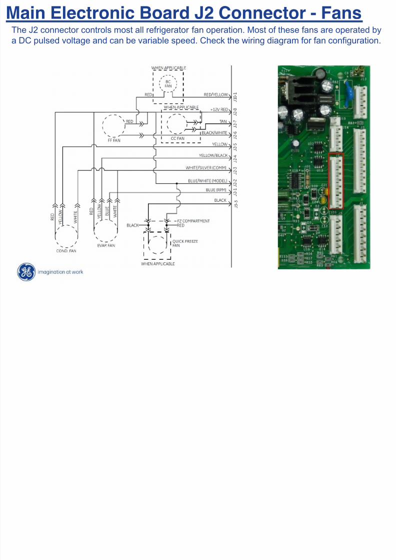
Main Electronic Board J2 Connector - FansThe J2 connector controls most all refrigerator fan operation. Most of these fans are operated by
a DC pulsed voltage and can be variable speed. Check the wiring diagram for fan configuration.
F O i

7/26/2019 GE Electronic Refrigerator Diagnostics Part II
http://slidepdf.com/reader/full/ge-electronic-refrigerator-diagnostics-part-ii 20/52
Fan OperationFans in the electronic refrigerators are DC fans and they operate on what we call Pulse Width
Modulation (PWM). Each fan is pulsed with voltage (frequency) to operate that specific fan
motor and can operate at different speeds depending on the PWM signal supplied to that fan
motor.
The pulses can not be measured with a voltmeter because the pulse has an ON point and an
OFF point (see the chart below). A voltmeter will average the ON and OFF points to read
what we call “effective voltage” and that is what the chart below shows.
The slower the fan speed, the longer the OFF point will be, the faster the fan speed the
longer the ON point will be; and for the fastest speed the PWM is constant.

7/26/2019 GE Electronic Refrigerator Diagnostics Part II
http://slidepdf.com/reader/full/ge-electronic-refrigerator-diagnostics-part-ii 21/52
Main Electronic Board J2 Connector Fans

7/26/2019 GE Electronic Refrigerator Diagnostics Part II
http://slidepdf.com/reader/full/ge-electronic-refrigerator-diagnostics-part-ii 22/52
Most fans receive supply voltage through the J2 pin 8 supply circuit as long as the refrigerator is
connected to AC power.
The supply voltage can be measured by placing your meter leads across J2 pin 8 and J2 pin 3. You
should read 12vdc. The presence of this voltage does NOT indicate that a fan should be operating.
Main Electronic Board J2 Connector - Fans
"+,. *%.* .+#5'4 7% &%$1#$-%4 6,*+ *+% 1(3. )#33%)*%48
Main Electronic Board J2 Connector Fans

7/26/2019 GE Electronic Refrigerator Diagnostics Part II
http://slidepdf.com/reader/full/ge-electronic-refrigerator-diagnostics-part-ii 23/52
Fan operation begins when the main board sends a “signal” voltage to the specific fan motor that needs
to operate. This “signal” voltage is read between the J2 pin 3 and J2 pin 5 for the condenser fan, J2 pin 3
and J2 pin 4 for the evaporator fan, and J2 pin 6 and J2 pin 8 for the fresh food fan.
The voltage will depend on what speed the fan motor is supposed to operate at and the voltages will vary
between 4vdc up to 12vdc.
Main Electronic Board J2 Connector - Fans
M i El t i B d J2 C t F

7/26/2019 GE Electronic Refrigerator Diagnostics Part II
http://slidepdf.com/reader/full/ge-electronic-refrigerator-diagnostics-part-ii 24/52
Some fan motors send an RPM signal back to the main board, this signal lets the board
monitor the fan speed. If this signal is not detected by the main board, the main board will
default the fan to a fixed speed. This DC voltage feedback can be read from the RPM wire
to the fan common connection.
Not all models use an RPM feed back, the schematic will show (RPM) for the feedback
wire.
Main Electronic Board J2 Connector - Fans
M i El t i B d J2 C t F

7/26/2019 GE Electronic Refrigerator Diagnostics Part II
http://slidepdf.com/reader/full/ge-electronic-refrigerator-diagnostics-part-ii 25/52
Main Electronic Board J2 Connector - Fans
C,$% )#'#$. )(3 0($>M )+%): *+% .)+%-(*,) 6,*+ *+% 53,*8
R#*%V WX RX" $%0%$.% *+% 7(**%$> '%(4. ,3 *+,.*%.*M *+% 1(3 -#*#$ 6,'' 7% 4(-(2%48
Main Electronic Board J2 Connector Fans

7/26/2019 GE Electronic Refrigerator Diagnostics Part II
http://slidepdf.com/reader/full/ge-electronic-refrigerator-diagnostics-part-ii 26/52
In some cases a fan motor can fail and take down the 12vdc supply on the main board. If the
refrigerator is not running and this voltage check fails; remove the J2 connector from the main
board. If the refrigerator compressor starts, suspect a bad fan motor. You can isolate the
condenser fan by unplugging it directly and then reinstall the J2 connector. If the refrigerator
stops running, the evaporator fan is shorted, if not the condenser fan is shorted.
Main Electronic Board J2 Connector - Fans
Main Electronic Board J2 Connector Fans

7/26/2019 GE Electronic Refrigerator Diagnostics Part II
http://slidepdf.com/reader/full/ge-electronic-refrigerator-diagnostics-part-ii 27/52
Main Electronic Board J2 Connector - Fans
Some main boards have ! watt resistors in the fan circuit directly located to the J2
connector.
If you should find a burnt resistor, replace the main board and the fan motor – thefan motor has shorted out which caused the resistor to burn. The evaporator fan
resistor is closest to the capacitors and the condenser fan resistor is farthest from
the capacitors.
7/26/2019 GE Electronic Refrigerator Diagnostics Part II
http://slidepdf.com/reader/full/ge-electronic-refrigerator-diagnostics-part-ii 28/52
ARCTICA
SXS
REFRIGERATOR
INVERTER
COMPRESSOR

7/26/2019 GE Electronic Refrigerator Diagnostics Part II
http://slidepdf.com/reader/full/ge-electronic-refrigerator-diagnostics-part-ii 29/52
TECHNICAL SERVICE GUIDE
Pub # 31-9090
Arctica Side-By-Side RefrigeratorInverter Compressor
Low Noise - High Performance

7/26/2019 GE Electronic Refrigerator Diagnostics Part II
http://slidepdf.com/reader/full/ge-electronic-refrigerator-diagnostics-part-ii 30/52
NOMENCLATURE
PSH23SGNAFBS
P --- Brand / ProductS --- Configuration
H --- Power (Inverter Compressor)23 --- VolumeS --- Interior / ShelvesG --- Icemaker / ExteriorN --- Model Year
A --- Engineering NomenclatureF --- Door TypeBS --- Exterior Color

7/26/2019 GE Electronic Refrigerator Diagnostics Part II
http://slidepdf.com/reader/full/ge-electronic-refrigerator-diagnostics-part-ii 31/52
!""#$"%&$
(#)*%+# "#+,$%+%!$
!"#$% '"()%$**"% +,%"-., /01$%2$% 30456
+-../012.3 0-456/77-6 826/019: 1- !;+ 5-</6<299 6/7=91 2. 5/64>./.1 0-456/77-6 8>4>3/?

7/26/2019 GE Electronic Refrigerator Diagnostics Part II
http://slidepdf.com/reader/full/ge-electronic-refrigerator-diagnostics-part-ii 32/52
INVERTER COMPRESSOR
• The new inverter compressor does notreceive 120 VAC from the main control
board, as in previous models.
• The inverter compressor receives it’spower from the inverter.
• It is not possible to start the compressor
without the inverter.

7/26/2019 GE Electronic Refrigerator Diagnostics Part II
http://slidepdf.com/reader/full/ge-electronic-refrigerator-diagnostics-part-ii 33/52
INVERTER COMPRESSOR con’t
• The compressor is a reciprocating, variable speed, 4pole type.
• It operates on 3-phase, 80 to 230 VAC within a
range of 57 to 104 Hz.• Compressor speed is controlled by voltage,
frequency and pulse wave modulation.
• Increasing frequency from the inverter will producean increase in compressor speed.

7/26/2019 GE Electronic Refrigerator Diagnostics Part II
http://slidepdf.com/reader/full/ge-electronic-refrigerator-diagnostics-part-ii 34/52
INVERTER COMPRESSOR con’t
• NOTE: Many voltmeters will not be able to read thevoltage output from the inverter.
• Compressor wattages at various speeds are:
LOW - 65 Watts
MED - 100 Watts
HIGH - 150 Watts

7/26/2019 GE Electronic Refrigerator Diagnostics Part II
http://slidepdf.com/reader/full/ge-electronic-refrigerator-diagnostics-part-ii 35/52
INVERTER COMPRESSOR con’t
• Compressor speed is based on the temperaturesetpoint in conjunction with the cabinet temperature.
8°F to 19.5°F above setpoint = high speed
3.5°F to 7.5°F above setpoint = medium speed
1°F to 3°F above setpoint = low speed
• NOTE: The compressor will run at medium speed if
the cabinet temperature is 20°F or more above the
setpoint.

7/26/2019 GE Electronic Refrigerator Diagnostics Part II
http://slidepdf.com/reader/full/ge-electronic-refrigerator-diagnostics-part-ii 36/52
INVERTER COMPRESSOR con’t
• The use of 3-phase power eliminates the need forthe PTCR relay, capacitor, and individual start and
run windings.
• Compressor pin functions are identical andcompressor lead wire configuration is of no
importance.
• A resistance of 9 to 11 ohms should be read
between any 2 of 3 pins.

7/26/2019 GE Electronic Refrigerator Diagnostics Part II
http://slidepdf.com/reader/full/ge-electronic-refrigerator-diagnostics-part-ii 37/52
INVERTER COMPRESSOR con’t
• Should an open or short occur in the compressor
winding or should one of the compressor lead wires
become open or disconnected, the inverter will stop
voltage output to the compressor.• High compressor torque enables the compressor to
start against high pressure in the sealed system.

7/26/2019 GE Electronic Refrigerator Diagnostics Part II
http://slidepdf.com/reader/full/ge-electronic-refrigerator-diagnostics-part-ii 38/52
INVERTER COMPRESSOR con’t
• Compressor and sealed system operation is extremelysmooth & cool.
• The compressor exterior may be room temperature while
operating.
• A running unit may be difficult to detect.
• To verify that the compressor is running:
Remove power from the unit and place a hand on the
compressor. Reconnect power and feel for a vibration whenthe compressor tries to re-start.
ACCESSING THE INVERTER

7/26/2019 GE Electronic Refrigerator Diagnostics Part II
http://slidepdf.com/reader/full/ge-electronic-refrigerator-diagnostics-part-ii 39/52
ACCESSING THE INVERTER- (Freestanding Inverter)
Remove the water valve and fresh food drain tube from the
cabinet. Carefully bend the process stub out of the way.
ACCESSING THE INVERTER

7/26/2019 GE Electronic Refrigerator Diagnostics Part II
http://slidepdf.com/reader/full/ge-electronic-refrigerator-diagnostics-part-ii 40/52
Remove the ¼” (1.6cm) hex head screw holding the inverter
to the mounting bracket.
Y<J Y<NW
ACCESSING THE INVERTER
ACCESSING THE INVERTER

7/26/2019 GE Electronic Refrigerator Diagnostics Part II
http://slidepdf.com/reader/full/ge-electronic-refrigerator-diagnostics-part-ii 41/52
Disengage the inverter from the mounting bracket by twisting
to the left and pulling it from the cabinet.
ACCESSING THE INVERTER

7/26/2019 GE Electronic Refrigerator Diagnostics Part II
http://slidepdf.com/reader/full/ge-electronic-refrigerator-diagnostics-part-ii 42/52
ACCESSING THE INVERTER - (Mounted Inverter)
• @%-#0% *+% +%EZ+%(4 .)$%6 *+(*
+#'4. *+% 6(*%$ 0('0% *# *+% )(7,3%* M
*+%3 )($%15''> &5'' *+% 6(*%$ 0('0% #5*
1$#- *+% )(7,3%* 8
• W,.)#33%)* *+% H 6,$% +($3%..%. *#
*+% ,30%$*%$8
• @%-#0% *+% +%EZ+%(4 .)$%6 (34 *+%
,30%$*%$ 2$#534 6,$% 1$#- *+%
)(7,3%*8
W,.)#33%)*
[30%$*%$ ;$#534 C,$%
ACCESSING THE INVERTER

7/26/2019 GE Electronic Refrigerator Diagnostics Part II
http://slidepdf.com/reader/full/ge-electronic-refrigerator-diagnostics-part-ii 43/52
ACCESSING THE INVERTER
• +% ,30%$*%$ ,. (**()+%4 *# *+%
)#-&$%..#$ 7> ( ',& (7#0% *+%
)#-&$%..#$ *%$-,3('.M ( *(7
B'#)(*%4 (* *+% 7#**#- $%($ )#$3%$IM
(34 ( A+,'',&.Z+%(4 .)$%6
• @%-#0% *+% A+,'' ,&.Z+%(4 .)$%6 1$#-
*+% ,30%$*%$8
• \,1* (34 $#*(*% *+% ,30%$*%$
)#53*%$)'#):6,.%8
• W,.)#33%)* *+% )#-&$%..#$ +($3%.. 1$#-
*+% )#-&$%..#$ *%$-,3('.8
ACCESSING THE INVERTER

7/26/2019 GE Electronic Refrigerator Diagnostics Part II
http://slidepdf.com/reader/full/ge-electronic-refrigerator-diagnostics-part-ii 44/52
ACCESSING THE INVERTER
• "#$%&''(%) *'+(,)(,-./0 1,&2 %&2-,($$&,
)(,2#'3.$
NOTE: DO NOT ATTEMPT TO DIRECT-START THE COMPRESSOR
Inverter Compressor Testing

7/26/2019 GE Electronic Refrigerator Diagnostics Part II
http://slidepdf.com/reader/full/ge-electronic-refrigerator-diagnostics-part-ii 45/52
Inverter Compressor Testing
FI KZL]W^
HI FHG]N^
QI FG #+-.
Compressor & Inverter

7/26/2019 GE Electronic Refrigerator Diagnostics Part II
http://slidepdf.com/reader/full/ge-electronic-refrigerator-diagnostics-part-ii 46/52
Compressor & Inverter
• ^#--53,)(*,#3 .,23(' 1$#- -(,3)#3*$#' 7#($4 _FD %3(7'%. ,30%$*%$
#5*&5*BKZL ]W^ )#33%)*%4I
BFFZFD ]W^ 53&'522%4I
• ]($,(7'% 0#'*(2% #5*&5* *#
)#-&$%..#$ 1$#- ,30%$*%$
• <E)%..,0% )5$$%3* 4$(6 ` K(-&.Z.*#&. 7$,%1'>M FH (**%-&*.M #3% %0%$>FH .%)#34.M *+%3 a -,35*% $%.*8
• X&%$(*%. 7%*6%%3 aG]N^ (34HQG]N^
• YU $(32% #1 DP YU *# FGK YU
!"#$ &'()*"++'*,•
- ."+.+ .' (#/"
Inverter Line Voltage

7/26/2019 GE Electronic Refrigerator Diagnostics Part II
http://slidepdf.com/reader/full/ge-electronic-refrigerator-diagnostics-part-ii 47/52
Inverter Line Voltage
Measure the input AC voltage for the Inverter at the connector with
black & orange wires, you should measure ~120VAC.
Inverter Command Voltage

7/26/2019 GE Electronic Refrigerator Diagnostics Part II
http://slidepdf.com/reader/full/ge-electronic-refrigerator-diagnostics-part-ii 48/52
Inverter Command Voltage
b%(.5$% %,*+%$ (*)#33%)*#$ #$ (* _FD
&,3. FcH d K *#L]W^8
Inverter

7/26/2019 GE Electronic Refrigerator Diagnostics Part II
http://slidepdf.com/reader/full/ge-electronic-refrigerator-diagnostics-part-ii 49/52
•4 56 7(8 9 :;#)(
)(,2#'3.$ 1&,$#0'3. +&.)30(
Inverter
• <=> ?"@ A#);A#,($ %&''(%)(8
•55=56 ?"@"#$%&''(%)(8
•
B,(C/('%D%;3'0($%&2-,($$&,$-((8E
Compressor Terminals

7/26/2019 GE Electronic Refrigerator Diagnostics Part II
http://slidepdf.com/reader/full/ge-electronic-refrigerator-diagnostics-part-ii 50/52
Compressor Terminals
Read ~10Ω between any 2 terminals - ∞Ω to Compressor case.
Compressor (Review)

7/26/2019 GE Electronic Refrigerator Diagnostics Part II
http://slidepdf.com/reader/full/ge-electronic-refrigerator-diagnostics-part-ii 51/52
Compressor (Review)
• 3 Phase Compressor
Compressor wattages at various speedsare:
LOW - 65 watts (1700 rpm) 57Hz
• MED - 100 watts (2100 rpm) 70Hz
• HIGH - 150 watts (3120 rpm) 104Hz
Compressor speed is based on the temperature set point in conjunction with the
specific cabinet temperature. Speeds are selected according to the following
cabinet temperatures, with freezer temperature being the primary:
• 7°F to 19.5°F above freezer set point = high speed.
• 4.5°F to 6.5°F above freezer set point = medium speed.• 1°F to 4°F above freezer set point = low speed.
Note : The compressor will run at medium speed if the freezertemperature is 20°F or more above the set point.

7/26/2019 GE Electronic Refrigerator Diagnostics Part II
http://slidepdf.com/reader/full/ge-electronic-refrigerator-diagnostics-part-ii 52/52