Embed Size (px)
DESCRIPTION
PFSS6NKW service manual
Citation preview
GE AppliancesGeneral Electric CompanyLouisville, Kentucky 40225
31-916231-9162
Profi le Bottom Freezer
Technical Service GuideMarch 2008
GE Consumer & Industrial
PFSS6NKWPFSF6NKW

– 2 –
IMPORTANT SAFETY NOTICE
The information in this service guide is intended for use byindividuals possessing adequate backgrounds of electrical,electronic, and mechanical experience. Any attempt to repair amajor ap pli ance may result in personal injury and property damage. The man u fac tur er or seller cannot be responsible for the in ter pre ta tion of this in for ma tion, nor can it assume any liability in connection with its use.
WARNING
To avoid personal injury, disconnect power before servicing this prod uct . If electrical power is required for diagnosis or test purposes, disconnect the power immediately after performing the necessary checks.
RECONNECT ALL GROUNDING DEVICES
If grounding wires, screws, straps, clips, nuts, or washers used to complete a path to ground are removed for service, they must be returned to their original position and properly fastened.
GE Consumer & IndustrialTechnical Service Guide
Copyright © 2008All rights reserved. This service guide may not be reproduced in whole or in partin any form without written permission from the General Electric Company.

– 3 –
Table of Contents
Articulating Door Mullion ...........................................................................................................................................62
Auger Motor Assembly ................................................................................................................................................61
Circuit Boards ..................................................................................................................................................................65
Components .....................................................................................................................................................................29
Components Locator Views ......................................................................................................................................25
Compressor ......................................................................................................................................................................52
Condenser Fan ................................................................................................................................................................43
Control Board Connector Locator ..........................................................................................................................27
Control Features .............................................................................................................................................................19
Control Panel Operation .............................................................................................................................................67
Damper Assembly .......................................................................................................................................................56
Defrost Cycle ....................................................................................................................................................................24
Defrost Heaters ..........................................................................................................................................................49
Dispenser Assembly ....................................................................................................................................................54
Dispenser Display Assembly ....................................................................................................................................53
Dispenser Heater ..........................................................................................................................................................55
Dispenser Lock ................................................................................................................................................................24
Door Gaskets ....................................................................................................................................................................34
Duct Heater ...................................................................................................................................................................50
EMI Filter and Power Cord ..........................................................................................................................................51
Evacuation and Charging Procedure ................................................................................................................... 9
Freezer Basket and Drawer .......................................................................................................................................32
Freezer Door Handle ...................................................................................................................................................13
Freezer Evaporator .....................................................................................................................................................39
Freezer Evaporator Cover ........................................................................................................................................37
Freezer Fan .....................................................................................................................................................................40
Fresh Food Crispers and Pans .................................................................................................................................31
Fresh Food Door Handle ............................................................................................................................................12
Fresh Food Evaporator .............................................................................................................................................37
Fresh Food Evaporator Cover ................................................................................................................................35
Fresh Food Fan ...........................................................................................................................................................42
Fresh Food Shelves and Bins ....................................................................................................................................29
(Continued next page)
– 4 –
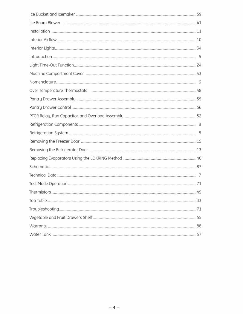
Ice Bucket and Icemaker ...........................................................................................................................................59
Ice Room Blower .........................................................................................................................................................41
Installation .......................................................................................................................................................................11
Interior Airfl ow .................................................................................................................................................................10
Interior Lights ...................................................................................................................................................................34
Introduction ...................................................................................................................................................................... 5
Light Time-Out Function .............................................................................................................................................24
Machine Compartment Cover ...............................................................................................................................43
Nomenclature .................................................................................................................................................................. 6
Over Temperature Thermostats .........................................................................................................................48
Pantry Drawer Assembly ..........................................................................................................................................55
Pantry Drawer Control ...............................................................................................................................................56
PTCR Relay, Run Capacitor, and Overload Assembly ....................................................................................52
Refrigeration Components ........................................................................................................................................ 8
Refrigeration System ................................................................................................................................................... 8
Removing the Freezer Door .....................................................................................................................................15
Removing the Refrigerator Door ...........................................................................................................................13
Replacing Evaporators Using the LOKRING Method .....................................................................................40
Schematic ..........................................................................................................................................................................87
Technical Data ................................................................................................................................................................. 7
Test Mode Operation ....................................................................................................................................................71
Thermistors .......................................................................................................................................................................45
Top Table ............................................................................................................................................................................33
Troubleshooting ..............................................................................................................................................................71
Vegetable and Fruit Drawers Shelf .......................................................................................................................55
Warranty ...........................................................................................................................................................................88
Water Tank .....................................................................................................................................................................57
– 5 –
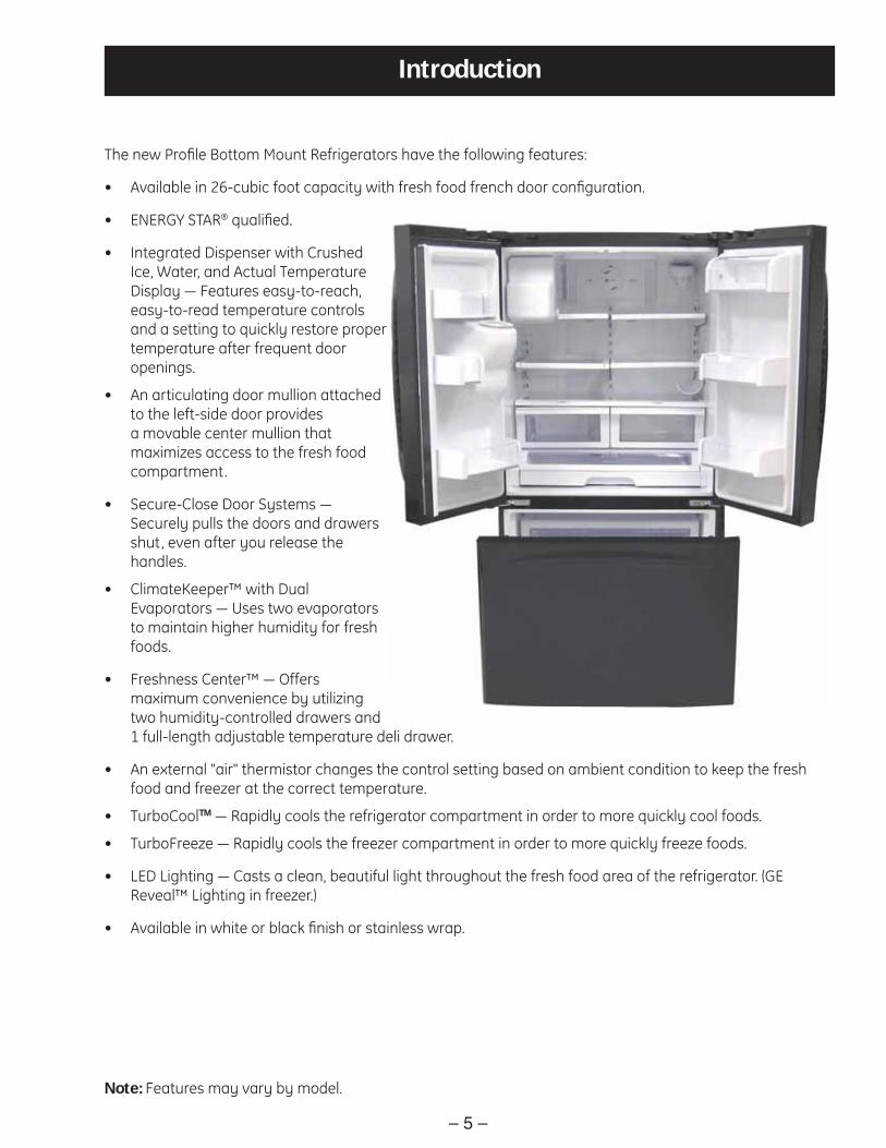
The new Profi le Bottom Mount Refrigerators have the following features:
Available in 26-cubic foot capacity with fresh food french door confi guration.•
ENERGY STAR• ® qualifi ed.
Integrated Dispenser with Crushed • Ice, Water, and Actual Temperature Display ― Features easy-to-reach, easy-to-read temperature controls and a setting to quickly restore proper temperature after frequent door openings.
• An articulating door mullion attached to the left-side door provides a movable center mullion that maximizes access to the fresh food compartment.
Secure-Close Door Systems ― • Securely pulls the doors and drawers shut, even after you release the handles.
• ClimateKeeper™ with Dual Evaporators ― Uses two evaporators to maintain higher humidity for fresh foods.
Freshness Center™ ― Offers • maximum convenience by utilizing two humidity-controlled drawers and 1 full-length adjustable temperature deli drawer.
An external "air" thermistor changes the control setting based on ambient condition to keep the fresh • food and freezer at the correct temperature.
TurboCool• TM ― Rapidly cools the refrigerator compartment in order to more quickly cool foods.
TurboFreeze ― Rapidly cools the freezer compartment in order to more quickly freeze foods.•
LED Lighting ― Casts a clean, beautiful light throughout the fresh food area of the refrigerator. (GE • Reveal™ Lighting in freezer.)
Available in white or black fi nish or stainless wrap.•
Introduction
Note: Features may vary by model.

– 6 –
Nomenclature
The nomenclature tag is located on the left wall of the fresh food compartment. It contains the following information:
Exterior ColorWW - White on WhiteBB - Black on BlackSS - Stainless Steel
Model Year W - 2007
Brand/Product P - Profi le
Capacity6 - 26 Cubic Foot
Mini-Manual Location
• Model and Serial Number
• Minimum Installation Clearances
• Electrical Voltage, Frequency
• Maximum Amperage Rating
• Refrigerant Charge and Type
Nomenclature
P F S S 6 N K W S S
ExteriorF - High GlossS - Stainless
Ice/WaterK - External Cubed & Crushed Ice &
Water, 1Year Filter/Icemaker
StyleS - Standard Depth
Confi gurationF - French Door w/FZ Drawer
Feature PackN - Full Width Meat Pan
The letter des ig nat ing the year re peats every 12 years.
Example: T - 1974 T - 1986 T - 1998
Serial NumberThe fi rst two numbers of the serial numberidentify the month and year of manufacture.Example: AR123456S = January, 2008
A - JAN 2008 - RD - FEB 2007 - MF - MAR 2006 - LG - APR 2005 - HH - MAY 2004 - GL - JUN 2003 - FM - JUL 2002 - DR - AUG 2001 - AS - SEP 2000 - ZT - OCT 1999 - VV - NOV 1998 - TZ - DEC 1997 - S

– 7 –
Technical Data
DISCONNECT POWER CORD BEFORE SERVICINGIMPORTANT - RECONNECT ALL GROUNDING DEVICESAll parts of this appliance capable of conducting electrical current aregrounded. If grounding wires, screws, straps, clips, nuts or washers usedto complete a path to ground are removed for service, they must bereturned to their original position and properly fastened.
ELECTRICAL SPECIFICATIONSTemperature Control (Position 5) ...........................................................16-(-11)°FDefrost Control (w/no door openings) ...........................................................16hrsThermistor kilo-ohm resistance .....................................................-2°F.......30.6.........................................................................................................38°F.......11.6.......................................................................................................77°F.........5.0kOvertemperature Thermostat ................................................................140-104°FDefrost Thermistor ............................................................................................50°FElectrical Rating: 115V AC 60 Hz ..................................................................5.2 AMaximum Current Leakage .......................................................................0.75 mAMaximum Ground Path Resistance .............................................................0.14
NO LOAD PERFORMANCEControl Position 5/5 and Ambient of 70°F to 90°FFresh Food, °F ........................................................................................33 to 42°FFrozen Food, °F .........................................................................................-7 to 3°FRun Time, % @ 70°F .................................................................................25 to 45Run Time, % @ 90°F .................................................................................45 to 75
REFRIGERATION SYSTEMCompressor 26 Model ...........................................................................897BTU/hrMinimum Equalized Pressure@ 90°F...............................................................................................60 to 65 PSIG@ 110°F.............................................................................................75 to 82 PSIG
REFRIGERANT CHARGE (R134a)26 Model ............................................................................................5.643 ounces
IMPORTANT SAFETY NOTICEThis information is intended for use by individuals possessing adequatebackgrounds of electrical, electronic and mechanical experience. Anyattempt to repair a major appliance may result in personal injury andproperty damage. The manufacturer or seller cannot be responsible forthe interpretation of this information, nor can it assume any liability inconnection with its use.

– 8 –
Refrigeration System
Refrigeration Components

– 9 –
Evacuation and Charging Procedure
WARNING:
• Before cutting or using a torch on refrigerant tubes, recover the refrigerant from the system using approved recovery equipment.
• Never charge new refrigerant through the purge valve. This valve is always located on the high pressure side of the system.
• Never apply heat from any source to a container of refrigerant. Such action will cause excessive pressure in the container.
• Always wear goggles when working with refrigerants and nitrogen holding charge in some replacement parts. Contact with these gases may cause injury.
1. Attach the hose from the R-134a charging cylinder to the process tube port on the compressor.
2. Evacuate the system to a minimum 20-in. vacuum using the refrigerator compressor and recovery pump, which is attached to the new drier assembly.
3. Turn off the recovery pump. Close the ball valve on the hose connected to the high-side port connection. Add 3 ounces of R-134a refrigerant to the system. Let the refrigerator operate and circulate the refrigerant for 5 minutes.
4. Open the ball valve. Recover the purge/sweep charge using the recovery pump and the refrigerator compressor until a 20-in. vacuum is attained. Close the ball valve and remove the recovery hose.
5. Charge the system with the exact amount of R-134a refrigerant specifi ed.
6. Disconnect the power cord to the refrigerator. This allows the pressure to equalize. After 3 to 5 minutes, the low side pressure will be positive and then the hose-to-charging port can be disconnected.
7. Using an electronic leak detector, check all brazed joints and both schrader ports. Reinstall caps to schrader.

– 10 –
Interior Airfl ow
FanFan
FanFan
(Air inlet)(Air inlet)(Air inlet)(Air inlet)
Heat exchangerHeat exchanger
FFaannFan
((AAiirr iinnlleett))(Air inlet)
Heat exchanger
Air Flow (side view) Air Flow (front view)
The fresh food evaporator fan forces air through the evaporator into the fresh food compartment. Air from the evaporator can also pass through the pantry room damper/heater assembly to the deli drawer, through the fresh food compartment, and return to the evaporator. The damper/heater assembly is controlled by the main control board. When open, the damper allows the chilled air from the fresh food evaporator to move into the deli drawer. Air returns from the fresh food compartment to the fresh food evaporator via two return vents located on the top left and right sides of the evaporator cover.
The freezer evaporator fan forces air through the evaporator into the freezer compartment. An additional ice room fan circulates air into and returns air from the ice room via plastic conduits embedded in the cabinet foam insulation. Air returns from the freezer compartment to the freezer evaporator via two return vents located on the bottom of the evaporator cover.

– 11 –
Installation
POWER CORD
The power cord of this appliance is equipped with a 3-prong (grounding) plug, which mates with a standard 3-prong (grounding) wall outlet to minimize the possibility of electric shock hazard from this appliance.
Have the wall outlet and circuit checked by a qualifi ed electrician to make sure the outlet is properly grounded.
If the outlet is a standard 2-prong outlet, it is your personal responsibility and obligation to have it replaced with a properly grounded 3-prong wall outlet.
WARNING: Do not, under any circumstances, cut or remove the third (ground) prong from the power cord. For personal safety, this appliance must be properly grounded.
The refrigerator should always be plugged into its own individual electrical outlet, which has a voltage rating that matches the rating plate.
USE OF EXTENSION CORDS
Because of potential safety hazards under certain conditions, we strongly recommend against the use of an extension cord.
However, if you must use an extension cord, it is absolutely necessary that it be a UL-listed (in the United States) or a CSA-listed (in Canada), 3-wire grounding type appliance extension cord having a grounding type plug and outlet, and that the electrical rating of the cord be 15 amperes (minimum) and 120 volts.
REFRIGERATOR LOCATION
• Do not install the refrigerator where thetemperature will go below 60°F (16°C) because itwill not run often enough to maintain propertemperatures.
• Do not install the refrigerator where thetemperature will go above 100°F (37°C) because itwill not perform properly.
• Install it on a floor strong enough to support it fullyloaded.
CLEARANCES
Allow the following clearances for ease of installation,proper air circulation and plumbing and electricalconnections.
Sides 1/8″ (3 mm)Top 1″ (25 mm)Back 1″ (25 mm)

– 12 –
Fresh Food Door Handle
REMOVE THE FRESH FOOD DOOR HANDLE Stainless steel:
REMOVINGTHE DOORHANDLE: Loosenthe set screwswith the 3/32″Allen wrench and remove the handle.
Plastic handle: REMOVINGTHE DOORHANDLE: Slidethe handle upand off of themountingfasteners.
NOTE: If the handle mounting fasteners need tobe tightened or removed, use a Phillips-headscrewdriver.
A
A
4
MountingFasteners
MountingFasteners
Badge
Badge
A
A
ATTACH THE FRESH FOODDOOR HANDLEStainless steel handle:
Attach the handleto the handlemountingfasteners andtighten the setscrews with a3/32“ Allenwrench.
Plastic handle:Attach the handle to the handle mountingfasteners by aligning the slots with the handlemounting fasteners.Slide it down until it is firmly locked intoposition.
A
A
6
A
MountingFasteners
Mountingfasteners
Slotson backof handle
A
A
ATTACH THE FRESH FOODATTACH THE FRESH FOODDOOR HANDLEDOOR HANDLEStainless steel handle:Stainless steel handle:
Plastic handle:Plastic handle:

– 13 –
Freezer Door Handle Removing the Refrigerator Door
REMOVE THE REFRIGERATOR DOORSOpen the refrigerator doors.Remove the two caps with a flat-headscrewdriver.Remove the three screws on top with a Phillips-head screwdriver.
Disengage the two electrical connectors.
To disconnect the water coupling, push in on thegray color of the coupling and pull out the tubing.
Remove the two grounding cables with a Phillips-head screwdriver.
Remove three 10 mm hex-head bolts (right and left).
CAUTION: When the bolts areremoved, the door may fall and cause personalinjury and/or damage to the door itself.
E
F
G
A
B
C
D
6
(Continued next page)
REMOVE THE FREEZER DOORHANDLEStainless steel and plastic handles:
Loosen the set screws located on the undersideof the handle with the 1/8″ Allen wrench andremove the handle.
NOTE: If the handle mounting fasteners need tobe tightened or removed, use a Phillips-headscrewdriver.
A
5
A
ATTACH THE FREEZER DOORHANDLEStainless steel and plastic handles:
Attach the handle firmly to the mountingfasteners and tighten the set screws on thebottom of the handle with a 1/8″ Allen wrench.
A
7
A
– 14 –
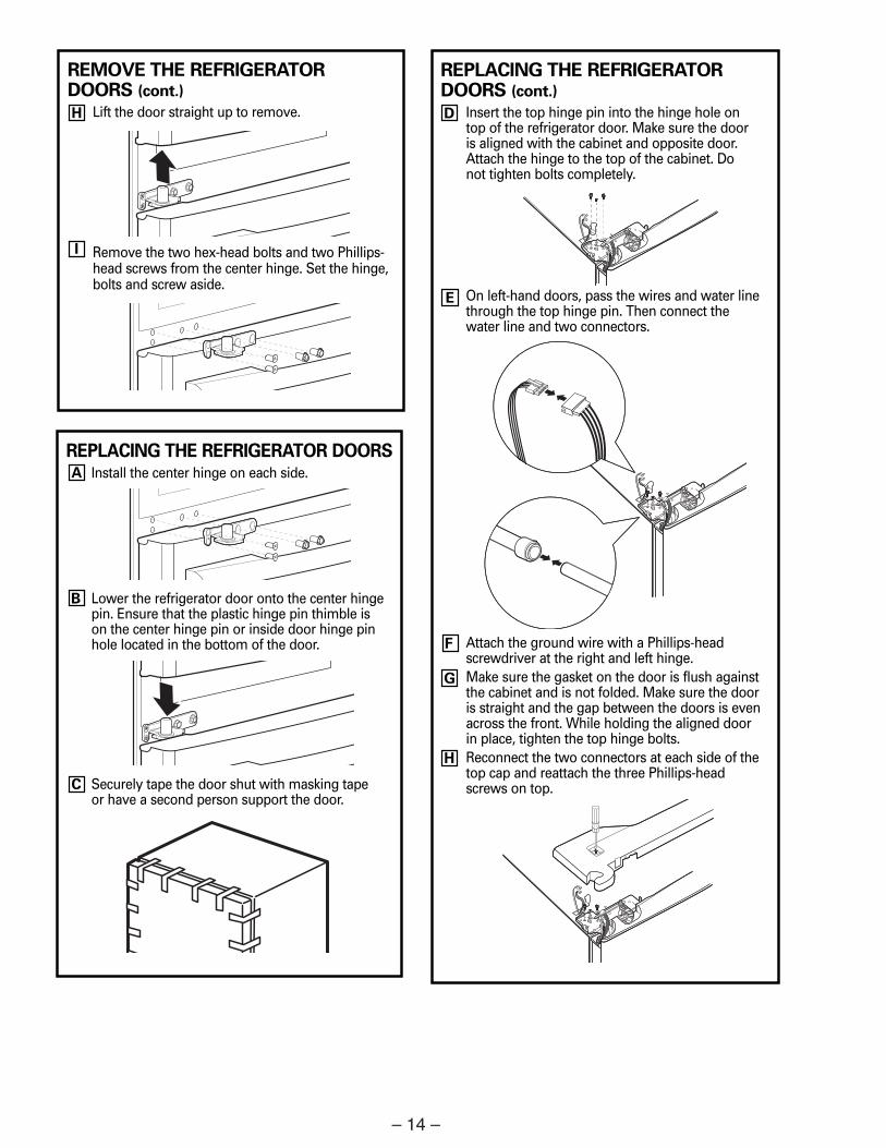
REPLACING THE REFRIGERATOR DOORSInstall the center hinge on each side.
Lower the refrigerator door onto the center hingepin. Ensure that the plastic hinge pin thimble ison the center hinge pin or inside door hinge pinhole located in the bottom of the door.
Securely tape the door shut with masking tape or have a second person support the door.
A
B
C
REMOVE THE REFRIGERATOR DOORS (cont.)
Lift the door straight up to remove.
Remove the two hex-head bolts and two Phillips-head screws from the center hinge. Set the hinge,bolts and screw aside.
I
H
REPLACING THE REFRIGERATORDOORS (cont.)
Insert the top hinge pin into the hinge hole on top of the refrigerator door. Make sure the door is aligned with the cabinet and opposite door.Attach the hinge to the top of the cabinet. Do not tighten bolts completely.
On left-hand doors, pass the wires and water linethrough the top hinge pin. Then connect thewater line and two connectors.
Attach the ground wire with a Phillips-headscrewdriver at the right and left hinge.Make sure the gasket on the door is flush againstthe cabinet and is not folded. Make sure the dooris straight and the gap between the doors is evenacross the front. While holding the aligned doorin place, tighten the top hinge bolts.Reconnect the two connectors at each side of thetop cap and reattach the three Phillips-headscrews on top.
E
F
G
D
H

– 15 –
Removing the Freezer Door
(Continued next page)
REMOVE THE FREEZER DOOR (cont.)
Use the tip of a screwdriver to separate the railfrom the rail cover. Tilt the front end up and liftthe entire door.
Set the door front on a nonscratching surface.
Push the rail assemblies back into the cabinet.
CAUTION: Push both sides of the railassemblies back at the same time.
E
F
G
REPLACING THE FREEZER DOORTwo people may be required to complete this procedure.
ATTACH AND SECURE THE DRAWERFRONT TO THE SLIDES
Pull out the rail assemblies to the full length oneach side of the cabinet.
CAUTION: Make sure to pull out theside rails evenly.
A
1
REMOVE THE FREEZER DOORPull the freezer door open to full extension. Remove the freezer bin by pulling both bracketsupward at the same time. (See page 8.)
Take out the lower basket by lifting the basket upfrom the rail system. (See page 10.)
Remove the two 10 mm hex-head bolts from theright and left side.
A
B
C
D

– 16 –
REPLACING THE FREEZER DOOR (cont.)
Hang the freezer door front onto open slots on the sides.
Tighten screws completely. (There are four 10 mm hex-head bolts.)
REPLACE THE FREEZER BASKET
Replace the freezer basket by lowering it into the frame.
B
C
2
Slot
REPLACING THE FREEZER DOOR (cont.)
REPLACE THE FREEZER BIN
Hook the ends of the freezer bin into bothbrackets, and push down until they lock into place. (See page 8.)
3
LEVEL THE REFRIGERATORThe leveling legs have 2 purposes:
1) Leveling legs adjust so the refrigeratoris firmly positioned on the floor anddoes not wobble.
2) Leveling legs serve as a stabilizingbrake to hold the refrigerator securelyin position during operation andcleaning. The leveling legs also preventthe refrigerator from tipping.
Turn the leveling legs clockwise to raise therefrigerator, counterclockwise to lower it.
CAUTION: To avoid possiblepersonal injury or property damage, theleveling legs must be firmly touching the floor.
8
A
Flat-Head Screwdriver
(Continued next page)

– 17 –
LEVEL THE REFRIGERATOR DOORSRemember a level refrigerator is necessaryfor getting the doors perfectly even. If youneed help, review the previous section onleveling the refrigerator.
If you open the freezer door, you can seethe center hinge.Insert the supplied 4 mm Allen wrenchinto the shaft of the center hinge.
9
A
B
Whenthe leftdoor islowerthan therightdoor.
Whenthe leftdoor ishigherthan therightdoor.
Adjustmentpoint
Adjustmentpoint
LEVEL THE REFRIGERATOR DOORS (cont.)
Adjust the height by turning clockwise or counterclockwise. When you turncounterclockwise, the door will move up.
After adjusting the doors, please insert thesupplied fastener ring using a pair of pliersin the gap between the hinge grommet andthe center hinge. The number of fastenerrings you will need to insert depends on the gap.
NOTE: Four fastener rings are enclosedwith the refrigerator. Thickness of eachfastener ring is 0.04″.
9
D
C
LEVEL THE FREEZER DOOR
Locate the height adjuster in the freezerdoor. Slightly loosen the four Phillips-head screws from the door on each side(right and left).
Loosen the controller screw with aPhillips-head screwdriver to adjust thelevel.
10
A
B
(Continued next page)

– 18 –
LEVEL THE FREEZER DOOR (cont.)
Find the best position to align the doorslope.
After adjustment, tighten all the screws.
10
C
D
Example: The slope is about2 mm as shown below.
Rotate the height adjuster to +2.0to reduce the door slope.
ReferencePlane
Slope

– 19 –
Control Features
About the controls with temperature settings.
The temperature controls are preset in the factory at 38°F for the refrigerator compartmentand -2°F for the freezer compartment. Allow 24 hours for the temperature to stabilize to thepreset recommended settings.The temperature controls can display both the SET temperature as well as the actualtemperature in the refrigerator and freezer. The actual temperature may vary slightly fromthe SET temperature based on usage and operating environment.
To change the temperature, press and release theADJUST FREEZER or ADJUST REFRIGERATOR pad.The display will show the actual temperature. Tochange the temperature, tap either the ADJUSTFREEZER or ADJUST REFRIGERATOR pad until thedesired temperature is displayed.
Once the desired temperature has been set, the temperature display will return to the actualrefrigerator and freezer temperatures after 10seconds. Several adjustments may be required.
Each time you adjust controls, allow 24 hours for therefrigerator to reach the temperature you have set.
Changing the Temperature
NOTE: The refrigerator is shipped with protective film covering the temperature controls. If this film was not removed during installation, remove it now.
(Hold 3 secto Lock Control)
ICE OFF/LOCK
(Hold 3 secfor Turbo Cool)
ADJUSTREFRIGERATOR
Light ON/OFF(Hold 3 seconds)
ALARM/LIGHT
(Hold 3 secto Reset Filter)
ICE &WATER
(Hold 3 secfor Turbo Freeze)
ADJUSTFREEZER
ENERGYSAVER TURBO FREEZE TURBO COOL
RESET FILTER CUBED CRUSHED WATER
ICEOFF
˚F38˚ F Recommended
˚F-2˚ F Recommended
CLIMATE KEEPER

– 20 –
About Energy SaverThis product is equipped with an EnergySaver feature. The refrigerator is shippedwith the Energy Saver feature off.
Over time, moisture can form on the frontsurface of the refrigerator cabinet and
cause rust. If moisture does appear on thefront surface of the refrigerator cabinet,turn off the Energy Saver feature bypressing and releasing the ENERGY SAVERpad on the control panel.
5
About TurboCool™ and TurboFreeze.™ ge.com
How it WorksTurboCool rapidly cools the refrigeratorcompartment in order to more quickly cool foods. Use TurboCool when adding alarge amount of food to the refrigeratorcompartment, putting away foods after theyhave been sitting out at room temperatureor when putting away warm leftovers. It canalso be used if the refrigerator has beenwithout power for an extended period.
The compressor and fresh food fan will run immediately until the fresh foodtemperature cools to approximately 25°F (–4°C), maximum run time two-and-a-halfhours. After reaching 25°F (–4°C), freshfood compartment will run at cold settingfor one hour and return to the originalsetting value.
How to Use
Press and hold the ADJUST REFRIGERATORpad for 3 seconds until you hear the soundand the displays.
After TurboCool is complete, the refrigeratorcompartment will return to the originalsetting.
NOTES: The refrigerator temperaturecannot be changed duringTurboCool.
The freezer temperature is notaffected during TurboCool.
(Hold 3 secfor Turbo Cool)
ADJUSTREFRIGERATOR
About Door AlarmThe door alarm will sound if any door is open for more than 3 minutes. Thebeeping stops when you close the door.
ENERGYSAVER
About Dispenser LightPress and hold the ALARM/LIGHT pad for 3 seconds to turn on the dispenser light. To turn off, press and hold the pad againfor 3 seconds.
Light ON/OFF(Hold 3 seconds)
ALARM/LIGHT
How it WorksTurboFreeze rapidly cools the freezercompartment in order to more quickly cool foods. Use TurboFreeze when adding a large amount of food to the freezercompartment, putting away foods after theyhave been sitting out at room temperatureor when putting away warm leftovers. It canalso be used if the refrigerator has beenwithout power for an extended period.
The compressor and fresh food fan will run immediately and keep running for two-and-a-half hours.
How to Use
Press and hold the ADJUST FREEZER padfor 3 seconds until you hear the sound and the displays.
After TurboFreeze is complete, the freezercompartment will return to the originalsetting.
NOTES: The freezer temperature cannot be changed during TurboFreeze.
The refrigerator temperature is not affected during TurboFreeze.
When opening the freezer doorduring TurboFreeze, the fans willcontinue to run if they have cycled on.
(Hold 3 secfor Turbo Freeze)
ADJUSTFREEZER
This product is equipped with an Energy Saver feature. The refrigerator is shipped with the Energy Saver feature on. Over time, moisture can form on the front surface of the door mullion and dispenser recess and can cause rust. If moisture does appear on the front surface of the door mullion and dispenser recess, turn off the Energy Saver feature by pressing and releasing the ENERGY SAVERENERGY SAVER pad on the control panel.
– 21 –
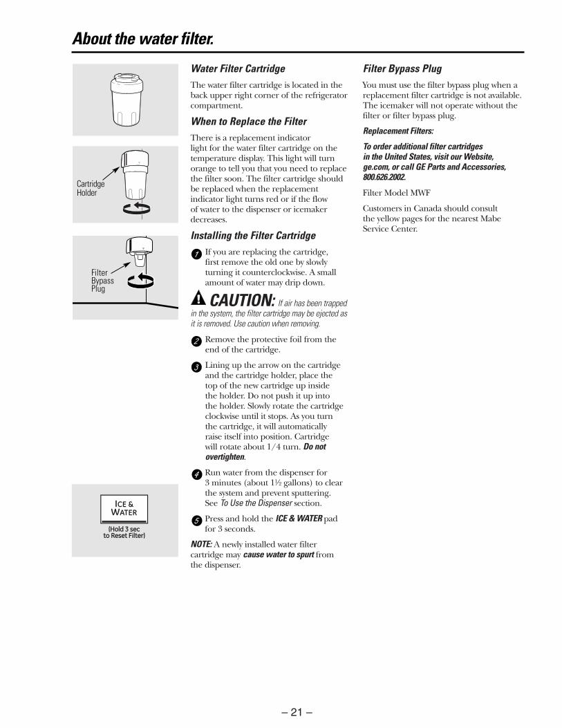
Water Filter CartridgeThe water filter cartridge is located in theback upper right corner of the refrigeratorcompartment.
When to Replace the FilterThere is a replacement indicator light for the water filter cartridge on thetemperature display. This light will turnorange to tell you that you need to replacethe filter soon. The filter cartridge shouldbe replaced when the replacementindicator light turns red or if the flow of water to the dispenser or icemakerdecreases.
Installing the Filter CartridgeIf you are replacing the cartridge, first remove the old one by slowlyturning it counterclockwise. A smallamount of water may drip down.
CAUTION: If air has been trappedin the system, the filter cartridge may be ejected asit is removed. Use caution when removing.
Remove the protective foil from theend of the cartridge.
Lining up the arrow on the cartridgeand the cartridge holder, place the top of the new cartridge up inside the holder. Do not push it up into the holder. Slowly rotate the cartridgeclockwise until it stops. As you turn the cartridge, it will automatically raise itself into position. Cartridge will rotate about 1/4 turn. Do notovertighten.
Run water from the dispenser for 3 minutes (about 11⁄2 gallons) to clearthe system and prevent sputtering. See To Use the Dispenser section.
Press and hold the ICE & WATER padfor 3 seconds.
NOTE: A newly installed water filtercartridge may cause water to spurt fromthe dispenser.
Filter Bypass PlugYou must use the filter bypass plug when areplacement filter cartridge is not available.The icemaker will not operate without thefilter or filter bypass plug.
Replacement Filters:
To order additional filter cartridges in the United States, visit our Website, ge.com, or call GE Parts and Accessories,800.626.2002.
Filter Model MWF
Customers in Canada should consult the yellow pages for the nearest MabeService Center.
About the water filter.
(Hold 3 secto Reset Filter)
ICE &WATER
CartridgeHolder
FilterBypassPlug

– 22 –
Refrigerator LightsAn authorized technician will need toreplace the LED light.
Replacing the light bulbs.
Freezer Light
CAUTION: Light bulbs may be hot.
Unplug the power cord from the outlet.
Pull drawer out to the stop position.
Rotate the shield down while pushing it backwards to remove it.
Turn the bulb counterclockwise.
Replace with an appliance bulb of thesame or lower wattage.
Replace the shield.
Plug the refrigerator back in.
NOTE: Appliance bulbs may be ordered from GEParts and Accessories, 800.626.2002.

– 23 –
About the automatic icemaker. ge.com
Automatic IcemakerThe icemaker will produce seven cubes per cycle—approximately 100–130 cubes in a 24-hour period, depending on freezercompartment temperature, roomtemperature, number of door openings and other use conditions.If the refrigerator is operated before thewater connection is made to the icemaker,turn on the ICE OFF feature by pressing andreleasing the ICE OFF/LOCK pad on thecontrol panel and the displays.When the refrigerator has been connectedto the water supply, turn off the ICE OFFfeature by pressing and releasing the ICEOFF/LOCK pad on the control panel.The icemaker will fill with water when itcools to 15°F (–10°C). A newly installedrefrigerator may take 12 to 24 hours tobegin making ice cubes.
You will hear a buzzing sound each time the icemaker fills with water.Throw away the first few batches of ice toallow the water line to clear.Be sure nothing interferes with the sweep of the feeler arm.When the bin fills to the level of the feelerarm, the icemaker will stop producing ice. It is normal for several cubes to bejoined together.If ice is not used frequently, old ice cubeswill become cloudy, taste stale and shrink. NOTE: In homes with lower-than-average waterpressure, you may hear the icemaker cycle multipletimes when making one batch of ice.NOTE: Turn on the ICE OFF feature if the watersupply is shut off.
ICEOFF
A newly installed refrigerator may take 12 to 24 hours to begin making ice.
To Use the DispenserSelect CUBED , CRUSHED or WATER
by pressing the ICE & WATER pad.Press the glass gently against the top of thedispenser cradle.The spill shelf is not self-draining. Toreduce water spotting, the shelf should be cleaned regularly.
If no water is dispensed when the refrigerator is firstinstalled, there may be air in the water line system.Press the dispenser arm for at least two minutes toremove trapped air from the water line and to fill thewater system. To flush out impurities in the waterline, throw away the first six full glasses of water.
CAUTION: Never put fingers or any other objects into the ice crusherdischarge opening.
To Lock and Unlock the DispenserTo lock, press and hold the ICE OFF/LOCKpad for 3 seconds. Repeat this step tounlock the dispenser.(Hold 3 sec
to Lock Control)
ICE OFF/LOCK
Dispenser LightPress and hold the ALARM/LIGHT pad for 3 seconds to turn the dispenser light onand off.
The light also comes on when the dispensercradle is pressed.
Light ON/OFF(Hold 3 seconds)
ALARM/LIGHT
Important Facts About Your Dispenser■■ Do not add ice from trays or bags to the storage drawer.
It may not crush or dispense well.■■ Avoid overfilling glass with ice and use of narrow glasses.
Backed-up ice can jam the chute or cause the door in thechute to freeze shut. If ice is blocking the chute, poke itthrough with a wodden spoon.
■■ Beverages and foods should not be quick-chilled in theice storage drawer. Cans, bottles or food packages in thestorage drawer may cause the icemaker or auger to jam.
■■ To keep dispensed ice from missing the glass, put theglass close to, but not touching, the dispenser opening.
■■ Some crushed ice may be dispensed even though youselected CUBED ICE. This happens occasionally when a fewcubes accidentally get directed to the crusher.
■■ After crushed ice is dispensed, some water may drip fromthe chute.
■■ Sometimes a small mound of snow will form on the door inthe ice chute. This condition is normal and usually occurswhen you have dispensed crushed ice repeatedly. The snow will eventually evaporate.
(Hold 3 secto Lock Control)
ICE OFF/LOCK
(Hold 3 secfor Turbo Cool)
ADJUSTREFRIGERATOR
Light ON/OFF(Hold 3 seconds)
ALARM/LIGHT
(Hold 3 secto Reset Filter)
ICE &WATER
(Hold 3 secfor Turbo Freeze)
ADJUSTFREEZER
ENERGYSAVER TURBO FREEZE TURBO COOL
RESET FILTER CUBED CRUSHED WATER
ICEOFF
˚F38˚ F Recommended
˚F-2˚ F Recommended
CLIMATE KEEPER
Spill Shelf
11
ICE &WATER
(Hold 3 secto Lock Control)
ICE OFF/LOCK

– 24 –
Defrost Cycle
Fresh Food Defrost Cycle
The refrigerator evaporator utilizes an adaptive defrost cycle that operates a metal sheath heater to remove frost from the evaporator.
If the main board senses any door opening, the defrost cycle is every 12 hours. Otherwise, the defrost cycle is 16 hours.
The control board determines the length of time the heater is energized. It does this by monitoring the fresh food evaporator thermistor. Once the temperature of the thermistor reaches 54°F (12°C), the control cycles the defrost heater off. A bimetal safety thermostat provides a backup in the event the evaporator thermistor fails. The safety thermostat prevents the temperature from exceeding 140°F (60°C).
Freezer Defrost Cycle
The freezer evaporator utilizes an adaptive defrost cycle that operates a metal sheath heater to remove frost from the evaporator.
If the main board senses any door opening, the defrost cycle is every 12 hours. Otherwise, the defrost cycle is 16 hours.
The control board determines the length of time the heater is energized. It does this by monitoring the freezer evaporator thermistor. Once the temperature of the thermistor reaches 50°F (10°C), the control cycles the defrost heater off. A bimetal safety thermostat provides a backup in the event the evaporator thermistor fails. The safety thermostat prevents the temperature from exceeding 140°F (60°C).
Dispenser Lock
When the dispenser system is locked, actual and set temperatures can be viewed but no dispenser command will be accepted. This includes the dispenser cradle and will prevent accidental dispensing that may be caused by children or pets. If a pad or the cradle is depressed with the system locked, it will not be acknowledged.
Light Time-Out Function
The refrigerator incorporates a light time-out function for the fresh food and freezer sections. If either of the fresh food doors or the freezer drawer is left open for 10 minutes, the main control board will turn off the lights in that section. If the open door or drawer is closed, and then reopened, the timer in the main control board will reset for another 10 minute count.

– 25 –
Components Locator Views
Fresh Food Compartment
Door Switch
Damper
LED Lights
Thermistor Location
(Continued next page)
Water Filter
Icemaker
Dispenser Water Tank
Fresh Food Evaporator Cover
Articulating Mullion Track
Fresh Food Evaporator (shown with cover removed)
Over Temperature Thermostat
Evaporator Thermistor
Evaporator
Defrost Heater
Evaporator Fan*
*The evaporator fan is attached to the inside of the cover.

– 26 –
Freezer Compartment
Rear View
Evaporator
Defrost Heater
Evaporator ThermistorOver Temperature
Thermostat
Light
Thermistor Location (behind light)
Compressor
DrierCondenser Fan
Condenser
Water Valve
Note: The evaporator fan is attached to the inside of the evaporator cover (not shown).
Noise Filter
Power Supply Board
Fresh Food LED Light Board
Main Control Board

– 27 –
Control Board Connector Locator
Main Control Board
(Continued next page)
CN73 CN72 CN71 CN70
CN91
CN90
CN75CN76CN32CN30
CN50
CN78
CN10
CN10 - Power Supply +5 VDC and +12 VDC Input
CN30 - FZ Door Switch, FF Left and Right Door Switches, FZ Sensor, FZ Defrost Sensor, FF Sensor, FF Defrost Sensor, Pantry Sensor
CN32 - Ambient Sensor, Ice Room Sensor
CN50 - Dispenser PBA Panel
CN70 - FZ Defrost Heater, FF Defrost Heater, Ice Pipe Heater, French Heater, Dispenser Heater
CN71 - Compressor, FZ Room Lamp
CN72 - Icemaker Heater, Icemaker G Motor
CN73 - Ice Cover Route G Motor, Icemaker Water Valve Solenoid, Dispenser Water Valve Solenoid, Auger Motor, Cube Motor
CN75 - FZ Fan Motor, FF Fan Motor, Compressor Fan Motor
CN76 - Ice Room Fan Motor
CN78 - FF LED Lights, Pantry Room Control, Water Tank Heater
CN90 - Icemaker, Icemaker Thermistor, Cycle Switch, Hall Sensors
CN91 - Pantry Room Damper
Pin 1
Pin 1
Pin 1
Pin 1
Note: Looking from behind the plugs into the board, pin#1 is always on the right side.

– 28 –
Power Supply Board
Fresh Food LED Light Board
CN1
CN2
CN1 - 115 VAC Input
CN2 - Power Supply +5 VDC and +12 VDC Output
Input
Output

– 29 –
Components
Rearranging the Shelves
To remove:
Remove all items from the shelf.
Tilt the shelf up at the front.
Lift the shelf up at the back and bring the shelf out.
To replace:
While tilting the shelf up, insert the tophook at the back of the shelf in a sloton the track.
Lower the front of the shelf until thebottom of the shelf locks into place.
Spillproof ShelvesSpillproof shelves have special edges to help prevent spills from dripping to lowershelves.
Shelves in the refrigerator compartment are adjustable.
Refrigerator Compartment
Quick Space Shelf This shelf splits in half and slides underitself for storage of tall items on the shelfbelow.
This shelf can be removed and replaced orrelocated (just like spillproof shelves).
Fresh Food Shelves and Bins
(Continued next page)

– 30 –
Non-Adjustable Bins on the DoorTo remove: Lift the bin straight up, then pull out.
To replace: Engage the bin in the moldedsupports on the door and push down. It will lock in place.
Adjustable Bins on the DoorAdjustable bins can easily be carried fromrefrigerator to work area.
To remove: Lift bin straight up, then pull out.
To replace or relocate: Slide in the bin justabove the molded door supports, and pushdown. The bin will lock in place.
Non-Adjustable Dairy BinTo remove: Lift the dairy bin straight up,then pull out.
To replace: Engage the bin in the moldeddoor supports and push down. The bin willlock in place.

– 31 –
Fresh Food Crispers and Pans
Fruit and Vegetable CrisperExcess water that may accumulate in thebottom of the drawers or under the drawersshould be wiped dry.
Adjustable Humidity CrisperSlide the control all the way to the high setting to provide high humidityrecommended for most vegetables.
Slide the control all the way to the lowsetting to provide lower humidity levelsrecommended for most fruits.
Adjustable Deli/Produce DrawerThe Adjustable Deli/Produce Drawer is a full-width drawer with adjustabletemperature control. This drawer can be used for large miscellaneous items.
There is a temperature control which canadjust the amount of cold air allowed intothe drawer.
The control is located on the right side ofthe drawer.
To remove:Pull the drawer out to the stop position.
Lift the front of the drawer up and out.
To replace:Lift the cover up.
Engage the pantry rollers into the side rails.
Push the drawer inwards (until it is in place).
How to Remove and Replace the Adjustable Deli/Produce Drawer
To remove:Pull the drawer out to the stop position.
Raise the front side of the divider to unhook it from the rear wall of the drawer.
To replace:Hook the back of the divider over therear wall of the drawer.
Push the divider down.
How to Remove and Replace Drawer Divider
Control
When Produce Drawer is selected, thetemperature of the drawer can be keptaround 38°F (3°C). This feature also helpskeep food fresh for a long time.
When Deli Drawer is selected, thetemperature of the drawer can be keptaround 34°F (1°C). This feature also helpskeep meat or fish fresh for a longer time.
NOTE: Fruits and vegetables may be damaged using the Deli Drawer setting. Do not store lettuce or other leafy produce in this drawer.
CAUTION: Do not store glass bottlesin this drawer. If they are frozen, they can break andcause personal injury.

– 32 –
Freezer Basket and Drawer
Freezer Basket and Drawer
Basket.
Drawer.
Basket RemovalTo remove:
Remove Freezer Bin. (See page 8.)
Pull basket out to the stop position.
Tilt up the rear of the bin.
Lift it out to remove.
To replace:
Place the basket into the rail assembly.
To remove:
Pull the drawer out to the stop position.
Remove both side knobs with a flat-head screwdriver.
Tilt up the rear of the drawer and liftstraight out.
To replace:
Pull both rails out to the stop position.
Place the drawer onto the rails andhook the support into the slots locatedon the side of the drawer.
Replace the side knob and push thedrawer back into place.
WARNING: Please do not losethe side knobs during disassembly since theymay present a choking hazard to children.
Basket Divider RemovalTo remove:
Pull basket out to the stop position.
Tilt up the rear of the bin.
Lift it out to remove.
To replace:
Hook the top corners of the dividerover the hole of the basket.
Drawer Removal
Non-Adjustable Bins in the FreezerTo remove: Pull the brackets upward untilyou hear a clicking sound and remove the bin.
To replace: Hook the ends of the bin intoboth brackets and push down until the binlocks into place.
8

– 33 –
Top Table
The top table is located on top of the refrigerator. The top table houses 2 reed switches and covers both door hinges, ambient sensor, wire harnesses, and the dispenser water tubing disconnect. Two hinge tabs position the top table over both door hinges and 3 screws attach it to the cabinet.
To remove the top table:
Open both doors. 1.
Insert a small fl at blade screwdriver under each 2. of the 2 top table caps, and carefully pry them away from the top table.
Remove the 3 recessed Phillips-head screws 3. that hold the top table to the cabinet.
Pull each side of the top table up to release each 4. hinge tab.
Place the top table upsidedown on top of the 5. cabinet and disconnect both reed switch wire harnesses.
Cap
Top Table
Door Reed Switches and Door Magnets
The top table houses 2 reed switches, (1 for each door). Each switch informs the main control board the status of each door, whether it is open or closed. Each switch is activated by a magnet recessed in the top of each door.
Replacement table tops are supplied with the switches installed. The switches are also available separately.
To replace the reed switches, it is necessary to remove the top table (See Top Table.) and place it inside-up on a protective surface.
Note: The reed switches may be lightly glued to the top table. It will be necessary to carefully pry and separate the switch from the glue.
Each reed switch is held in place by small tabs that can be carefully pried back.
Tab TabReed Switch
(Continued next page)

– 34 –
Interior Lights
Freezer Light
To replace the freezer light:
Unplug the refrigerator. 1. Remove the freezer upper drawer.2. (See Control Features.) Press in on the back of the light cover then lower 3. it down and out.
Replace the bulb with an appliance bulb of the 4. same or lower wattage, and reinstall the light cover.
Note: When reinstalling the light cover, make sure all top tabs snap securely in place.
Reinstall the upper drawer and plug the 5. refrigerator back in.
Refrigerator LED Light
To replace the refrigerator LED light:
Unplug the refrigerator. 1. Press in on the back of the LED light cover then 2. lower it down.
Door Gaskets
The fresh food and freezer doors have magnetic gaskets that create a positive seal to the front of the steel cabinet. The magnetic door gaskets are secured to the doors by a barbed edge that locks into a retainer channel.
To remove and replace the door gasket:
1. Starting at any corner, pull the old gasket out of the retaining channel.
2. Soak the new gasket in warm water to make it pliable.
3. Push the barbed edge of the gasket into the retainer channel.
Each door magnet is located in a recess at the top of each door. Using a small fl at blade screwdriver, each magnet can be removed by carefully prying each side out from the recess.
Pry Pry
(Continued next page)

– 35 –
Disconnect the LED light and the sensor wire 4. harnesses.
Remove the 2 Phillips-head screws that hold 3. the LED light housing to the ceiling of the refrigerator.
Remove the 2 Phillips-head screws and the LED 5. board.
Fresh Food Evaporator Cover
The fresh food evaporator cover is held to the back wall of the refrigerator with a Phillips-head screw and 2 tabs.
To remove the fresh food evaporator cover:
Remove the 2 fruit and vegetable drawers and 1. the shelves that are in front of the evaporator cover.
Using a small fl at blade screwdriver, pry off the 2. cap from the top of the shelf angle.
3. Remove the 2 Phillips-head screws that attach the shelf angle to the cover.
4. Remove the 2 Phillips-head screws that hold the evaporator cover to the back wall.
Cap
Shelf Angle
(Continued next page)

– 36 –
5. Grasp the shelf angle near the bottom and pull it out and down.
Note: Behind the cover there is a recessed area in the back wall that houses the evaporator assembly. The top of the cover is inserted into the top of the recess and the sides have small arrows that indicate the location of 6 tabs that lock into the recess.
Top of Recessed Area
6. Pull the cover out at the bottom, then lower the cover.
7. Turn the front of the cover towards the icemaker and disconnect the evaporator fan motor wire harness.
Disconnect

– 37 –
Fresh Food Evaporator
WARNING: Sharp edges may be exposed when servicing. Use caution to avoid injury. Wear Kevlar gloves or equivalent protection.
The following components must be removed in the appropriate order to access the fresh food evaporator:
Remove the fresh food evaporator cover. (See 1. Fresh Food Evaporator Cover.)
Push in the sides of the housing cover and pull 2. out the cover.
3. Disconnect the 3 fresh food evaporator defrost component harnesses.
1
2
3
Defrost ComponentsNo. Component Wire Colors1 Bimetal Thermostat Red and Black2 Defrost Heater Tan3 Thermistor Yellow
Housing Cover
(Continued next page)
4. Peel off the refl ective tape from the drain tray.
5. Remove the 2 Phillips-head screws that hold the evaporator to the back wall of the refrigerator.
6. Carefully pull the evaporator up to remove the heat conducting tab from the drain inlet in the recess.
Refl ective Tape
Heat Tab
Freezer Evaporator Cover
The freezer evaporator cover is held to the back wall of the refrigerator with 2 recessed Phillips-head screws.
To remove the freezer evaporator cover:
Remove the freezer basket and drawer. (See 1. Freezer Basket and Drawer.)
Remove the four 10-mm hex-head bolts (2 on 2. each side) that attach the drawer front to the rail assembly.

– 38 –
3. Tilt the bottom of the drawer out and lift the drawer off the rail assembly.
4. Place the drawer front on a protected surface.
8. Lift the bottom of the cover up and pull cover towards the front of the refrigerator.
9. Disconnect the 3 freezer evaporator cover component harnesses.
Disconnect
Disconnect
Disconnect
Lock Tab
Note: Behind the cover there is a recessed area in the back wall that houses the evaporator assembly. The cover is held in place by 2 recessed Phillips-head screws and 3 tabs inserted into the bottom of the recess.
7. Remove the 2 recessed Phillips-head screws that attach the cover to the back wall of the freezer compartment.
5. Using a fl at blade screwdriver, press in the rail lock tab on the left side rail cover then slide the rail out slightly to cover the lock tab. Repeat this procedure on the right-side rail.
6. Evenly pull the rail assembly away from the refrigerator until both rails are clear of the cabinet.

– 39 –
3. Disconnect the 3 freezer evaporator defrost component harnesses.
1
2
3
Defrost ComponentsNo. Component Wire Colors1 Bimetal Thermostat Red and Black2 Defrost Heater Tan3 Thermistor Yellow
Housing Cover
Freezer Evaporator
WARNING: Sharp edges may be exposed when servicing. Use caution to avoid injury. Wear Kevlar gloves or equivalent protection.
The following components must be removed in the appropriate order to access the freezer evaporator:
Remove the freezer evaporator cover. (See 1. Freezer Evaporator Cover.)
Push in the sides of the housing cover and pull 2. out the cover.
4. Pull out the foam block from the right side of the evaporator.
5. Peel off the refl ective tape from the drain tray.
6. Carefully pull the evaporator out and up to remove the heat conducting tab from the drain inlet in the recess.
Heat Tab
Refl ective Tape
Foam Block

– 40 –
Freezer Fan
The freezer fan is attached to the inside of the freezer evaporator cover.
To remove the freezer fan assembly:
Remove the freezer evaporator cover (See 1. Freezer Evaporator Cover.) and place the cover assembly on a protected surface so that the inside faces upward.
Note the positioning of the wiring and untape 2. the wire harnesses.
3. Remove the plastic wire tie and the freezer fan wires from the retainer.
4. Remove the 4 Phillips-head screws that attach the fan housing to the evaporator cover.
Wire Tie
Retainer
Freezer Fan
Replacing Evaporators Using the LOKRING Method
Fresh Food Evaporator
Parts Needed:Fresh Food Evaporator • Drier Assembly • Access Tube (part # WJ56X61) • LOKRING• Connectors- (part # WR97X10031)
(part # WR97X10085) (part # WR97X10021)
Freezer Evaporator
Parts Needed:Freezer Evaporator • Drier Assembly • Access Tube (part # WJ56X61) • LOKRING• Connectors- (2 of part # WR97X10021)
The LOKRING method provides a durable, vibration resistant compression connection for both copper and aluminum tubing. The connectors can be used within a temperature range of -58°F (-50°C) to +302°F (150°C) and showed to have a higher burst strength than that of the tube itself. Refer to Service Guide #31-9067 for complete instructions on using the LOKRING method of installing an evaporator.
(Continued next page)

– 41 –
5. Remove the fan housing and place it blade side up on the protected surface.
Note: An anti-slip adhesive is applied to the fan blade hub during factory assembly and the fan blade may be diffi cult to remove.
6. Using 2 large fl at blade screwdrivers, place each screwdriver under the fan blade hub, 180° apart, and over 2 opposite legs of the housing as shown. Carefully pry up and remove the fan blade from the motor shaft.
7. Remove the 2 Phillips-head screws, then rotate the fan motor 90° counterclockwise and remove the motor from the fan housing.
Leg (1 of 4 )
Retainer
Ice Room Blower
The ice room blower is attached to the inside of the freezer evaporator cover.
To remove the ice room blower assembly:
Remove the freezer evaporator cover (See 1. Freezer Evaporator Cover.) and place the cover assembly on a protected surface so that the inside faces upward.
Note the positioning of the wiring and untape 2. the wire harnesses.
Remove the 2 plastic wire ties (not shown) and 3. the blower wires from all retainers.
Remove the 4 Phillips-head screws that attach 4. the blower housing to the evaporator cover.
Ice Room Blower Assembly
(Continued next page)

– 42 –
5. Remove the blower housing and place it blower wheel-side up on the protected surface.
Note: An anti-slip adhesive is applied to the blower wheel hub during factory assembly and the blower wheel may be diffi cult to remove.
6. Firmly grasp the blower wheel and pull it off the motor shaft.
7. Remove the 2 Phillips-head screws then rotate the blower motor 90° counterclockwise and remove the motor from the blower housing.
Refl ective Tape
Masking Tape
Note: The fan blade may be diffi cult to remove from the motor shaft. Care must be taken to avoid damage to the fan blade and/or fan housing.
4. Place the fan housing blade side up on a protective surface.
5. Using 2 large fl at blade screwdrivers, place each screwdriver under the fan blade hub, 180° apart, and over 2 opposite legs of the housing as shown. Carefully pry up and remove the fan blade from the motor shaft.
Screwdriver
Screwdriver
Fresh Food Fan
The fresh food fan motor is attached to the inside of the fresh food evaporator cover.
To remove the fresh food fan:
Remove the fresh food evaporator cover. (See 1. Fresh Food Evaporator Cover.)
Peel off the masking tape from the top and the 2. refl ective tape from the bottom of the fan motor housing.
Remove the 4 Phillips-head screws that attach 3. the fan housing to the evaporator cover.
Leg (1 of 4 )
(Continued next page)

– 43 –
6. Remove the 2 Phillips-head screws, then rotate the fan motor 1/4-turn counterclockwise and remove the motor from the fan housing.
Machine Compartment Cover
The machine compartment cover is held to the rear of the refrigerator with 8 Phillips-head screws and 2 tabs. After removing the screws the cover can then be lifted from the tabs.
Tab
Note: When installing the machine compartment cover, be sure to place the cover over the 2 tabs before installing screws.
Condenser Fan
The condenser fan motor is mounted in the machine compartment between the compressor and the condenser. The machine compartment cover must be properly installed to ensure air passes through the condenser. (See Machine Compartment Cover.)
Condenser Fan Parameters
Disconnect
Front Tab
Room Temperature Condenser Fan OperationAbove 66°F Fan operates with
compressor.61 - 65°F Fan has 5-minute delay,
then operates with compressor.
Below 60°F Condenser fan does not operate at all.
To remove the condenser fan:
Remove the machine compartment cover. (See 1. Machine Compartment Cover.)
Disconnect the fan wire harness.2.
Using a fl at blade screwdriver or fi ngertip, 3. simultaneously lift the front tab of the fan housing and pull the fan assembly out approximately 1 inch.
(Continued next page)

– 44 –
4. Rotate the fan assembly clockwise then carefully maneuver the fan assembly out of the machine compartment.
5. Using a fl at blade screwdriver, remove the spring clip.
6. Pull the fan blade off the motor shaft.
Spring Clip
8. Remove the 2 Phillips-head screws from the fan housing.
9. Using a fl at blade screwdriver or fi ngertips, lift and spread each of the 2 tabs on the motor clamp and pull the fan motor out of the housing.
7. Note the routing of the wiring through the retainers and the position of the motor and clamp. Remove the wiring from the retainers.
Retainer
Retainer
Retainers

– 45 –(Continued next page)
Note: To accurately test a thermistor, place the thermistor in a glass of ice water (approximately 33°F (0.5°C)) for several minutes and check for approximately 12.7K Ω.
Thermistor Resistance
Temperature (°F)
Temperature (°C)
Resistance in Kilo-Ohms
-40 -40 88 kΩ
-31 -35 67.6 kΩ
-22 -30 52.4 kΩ
-13 -25 40.9 kΩ
-4 -20 32.2 kΩ
5 -15 25.6 kΩ
14 -10 20.4 kΩ
23 -5 16.4 kΩ
32 0 13.2 kΩ
41 5 10.8 kΩ
50 10 8.9 kΩ
59 15 7.3 kΩ
68 20 6.1 kΩ
77 25 5 kΩ
86 30 4.2 kΩ
95 35 3.5 kΩ
104 40 3 kΩ
113 45 2.5 kΩ
122 50 2.2 kΩ
131 55 1.9 kΩ
140 60 1.6 kΩ
Thermistors Fresh Food Thermistor
The fresh food thermistor is inserted in a recess located in the back of the fresh food LED light housing.
To access the thermistor it is necessary to remove the LED light housing. (See Interior Lights.)
The thermistor recess is covered with a foam insulator that must be peeled back to remove the thermistor.
Thermistor
Foam Insulator

– 46 –
Freezer Thermistor
The freezer thermistor is inserted in the thermistor cover located in the ceiling of the freezer compartment behind the light. To access the thermistor it is necessary to remove the freezer basket and drawer. (See Freezer Basket and Drawer.)
To remove the thermistor cover, insert a fl at blade screwdriver under the cover and gently pry the cover from the ceiling.
The thermistor is connected to the refrigerator with a wire harness.
Thermistor
Thermistor Cover
Disconnect
(Continued next page)
Fresh Food Evaporator Thermistor
To access the fresh food evaporator thermistor the fresh food evaporator cover must be removed. (See Fresh Food Evaporator Cover.) The housing cover can be removed to disconnect the wire harnesses to the thermistor. (See Fresh Food Evaporator.)
The fresh food thermistor is located on the evaporator inlet tube.
The thermistor wiring is attached to the evaporator with 2 plastic wire ties and is held to the inlet tube with a plastic clamp. The 2 tabs on the clamp can be pried open to release the thermistor.
Tab
TabThermistor

– 47 –
Freezer Evaporator Thermistor
To access the freezer thermistor the freezer evaporator cover must be removed. (See Freezer Evaporator Cover.) The housing cover can be removed to disconnect the wire harness to the thermistor. (See Freezer Evaporator.)
The freezer thermistor is located in a plastic holder attached to the evaporator.
The thermistor holder and the thermistor wiring are attached to the evaporator with 3 plastic wire ties. After the plastic wire ties are removed, the thermistor can be pulled out of the holder.
Thermistor
Holder
Ice Room Thermistor
The ice room thermistor is inserted in the auger motor cover. To replace the ice room thermistor the auger motor assembly must be removed. (See Auger Motor Assembly.)
The thermistor is connected to the auger motor assembly with a wire harness.
Thermistor
(Continued next page)
Pantry Thermistor
The pantry thermistor is inserted in the damper cover.
To replace the pantry thermistor:
Remove the damper assembly1. . (See Damper Assembly.)
Peel off the foam that seals the damper cover to 2. the back wall of the refrigerator.
3. Carefully pull out the damper assembly from the damper cover.
Foam Seal
4. Pull out the pantry thermistor from the damper cover.
Thermistor

– 48 –
Ambient Thermistor
The ambient thermistor is located under the right side of the top table.
To replace the ambient thermistor:
Note: In the following step you do not need to disconnect both reed switch wire harnesses.
Remove the top table1. . (See Top Table.)
Cut off the thermistor leads where they enter 2. the thermistor body.
3. Use plastic bell connectors and fi ll the connector with RTV102 silicone then splice a new thermistor into the wires as shown in the illustration.
RTV102
Thermistor
Cut Here
Cut Here
Over Temperature Thermostats
Fresh Food Over Temperature Thermostat
The over temperature thermostat is attached on a bracket located on the top left side of the evaporator. (See Component Locator Views.)
The thermostat wiring is attached to the evaporator with 2 plastic wire ties and the thermostat is held to the bracket with a metal clip. It is necessary to remove the FF evaporator from the recess to replace the over temperature thermostat. (See Fresh Food Evaporator.)
Bracket
Metal Clip
Over Temperature Thermostat
Left Side View of Evaporator
Freezer Over Temperature Thermostat
The over temperature thermostat is attached on a bracket located on the top right side of the evaporator. (See Component Locator Views.) The thermostat wiring is attached to the evaporator with a plastic wire tie and the thermostat is held to the bracket with a metal clip.
Top Right View of Evaporator
Over Temperature Thermostat
Bracket
Metal Clip

– 49 –
Defrost Heaters
Fresh Food Defrost Heater
The defrost heater is located on the sides and bottom of the evaporator.
The defrost heater wiring is attached to the evaporator with 4 plastic wire ties and the heater is held in 2 slots (1 on each side) at the bottom of the evaporator.
To remove the defrost heater:
Carefully bend open the tabs that form the 2 1. slots and pull down the heater.
Carefully pull the bottom of the evaporator 2. approximately 45 degrees from the recess.
Tab
Defrost Heater
Drain Tray
Slot
(Continued next page)
3. Using a small fl at bladed screwdriver, reach behind the drain tray and bend straight the 4 lock tabs that hold the evaporator to the drain tray.
4. Separate the drain tray from the evaporator.
5. Remove the defrost heater from the evaporator.
Note: When installing the heater to the drain tray, be sure heat tab is inserted into the drain tray outlet.
Rear View of Drain Tray
Lock Tab (1 of 4)

– 50 –
Freezer Defrost Heater
The defrost heater is located on the sides and bottom of the evaporator.
The defrost heater wiring is attached to the evaporator with 4 plastic wire ties and the heater is held in 4 slots) at the bottom of the evaporator.
To remove the defrost heater:
Remove the 4 plastic wire ties.1.
Remove the foam air block.2.
3. Peel off the refl ective tape.
4. Carefully bend open the tabs that form the 4 slots and pull down the heater.
5. Carefully pull the evaporator out and up to remove the heat conducting tab from the drain inlet in the recess.
Tab
Heat Tab
Refl ective Tape
Slot
Foam Air Block
(Continued next page)
6. Using a small fl at bladed screwdriver, reach behind the drain tray and bend straight the 2 lock tabs that hold the evaporator to the drain tray.
7. Separate the drain tray from the evaporator.
8. Remove the defrost heater from the evaporator.
Note: When installing the heater to the drain tray, be sure heat tab is inserted into the drain tray outlet.
Rear View of Drain Tray
Lock Tab (1 of 2)
Duct Heater
The duct heater is attached to the inside of the freezer evaporator cover. The duct heater prevents water from freezing and blocking air fl ow to the ice room.
The duct heater is in a parallel circuit with the freezer defrost heater. The heaters are in series with the bimetal defrost safety thermostat. Both heaters operate at 120 VAC when the freezer defrost circuit is energized by the main control board and the defrost safety thermostat is closed.
– 51 –
Retainer
To remove the duct heater:
Remove the freezer evaporator cover (See 1. Freezer Evaporator Cover.) and place the cover assembly on a protected surface so that the inside faces upward.
Note the positioning of the wiring and untape 2. the wire harnesses.
Remove the 2 plastic wire ties (not shown) and 3. the duct heater wires from all retainers.
Duct Heater Wire Harness
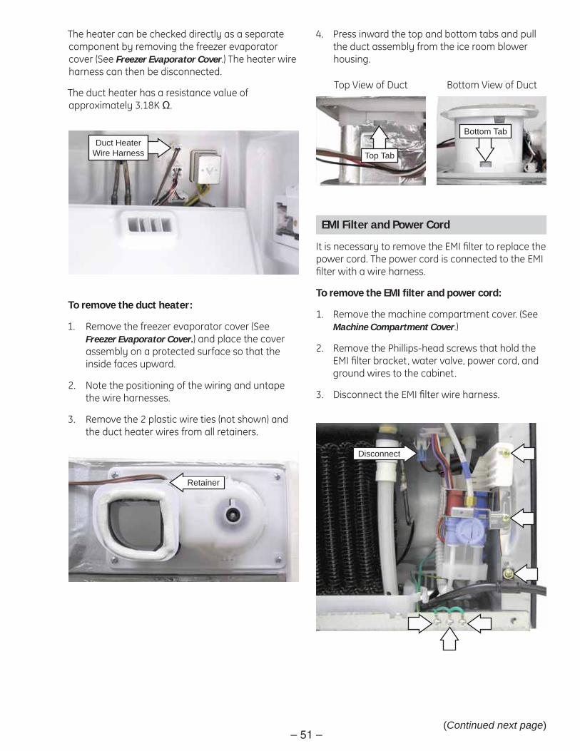
The heater can be checked directly as a separate component by removing the freezer evaporator cover (See Freezer Evaporator Cover.) The heater wire harness can then be disconnected.
The duct heater has a resistance value of approximately 3.18K Ω.
(Continued next page)
4. Press inward the top and bottom tabs and pull the duct assembly from the ice room blower housing.
Bottom Tab
Top Tab
Top View of Duct Bottom View of Duct
EMI Filter and Power Cord
It is necessary to remove the EMI fi lter to replace the power cord. The power cord is connected to the EMI fi lter with a wire harness.
To remove the EMI fi lter and power cord:
Remove the machine compartment cover. (See 1. Machine Compartment Cover.)
Remove the Phillips-head screws that hold the 2. EMI fi lter bracket, water valve, power cord, and ground wires to the cabinet.
Disconnect the EMI fi lter wire harness.3.
Disconnect

– 52 –
4. Position the water valve to the left side.
5. Pull the EMI fi lter bracket straight out.
6. Using a fl at blade screwdriver, press in the 2 tabs and open the bracket.
7. Disconnect the power cord wire harness.
8. Remove the 13 mm. hex nut and ground wire from the fi lter.
Disconnect
13 mm. Hex Nut
Ground Wire
PTCR Relay, Run Capacitor, and Overload Assembly
The PTCR relay, run capacitor, and overload assembly is held to the compressor by 2 legs at the bottom and a lock tab at the top.
To remove the PTCR relay, run capacitor, and overload assembly:
Remove the machine compartment cover. (See 1. Machine Compartment Cover.)
Disconnect the PTCR relay, run capacitor, and 2. overload wire harness.
3. Using a fl at blade screwdriver, press in the lock tab on top of the assembly and rotate the assembly counterclockwise.
Disconnect
Lock Tab
Compressor
The compressor is a reciprocating type. Refer to the mini-manual for the BTU/hour rating, refrigerant type, and correct charge for this model. A 1/4-in. O.D. copper tube is provided for access to the low pressure side of the refrigeration system.

– 53 –
Dispenser Display Assembly
The dispenser display assembly incorporates the interface used for temperature control and features and houses the dispenser LED lights. The display has 6 tabs that hold it to the dispenser recess.
To remove the dispenser display:
Remove the Phillips-head screw from the 1. housing.
2. Insert a small fl at-blade screwdriver into the small opening located at the bottom front corner of the display.
3. Pry the bottom right side of the dispenser display away from the dispenser recess.
4. Grasp display, pull it towards the right and remove it from the recess.
5. Disconnect the wire harness.
Caution: To prevent breaking tabs when installing the display, fi rst insert the left side tabs into the recess then snap the display in place.
Disconnect

– 54 –(Continued next page)
Dispenser Assembly
The dispenser assembly includes the duct door, duct door motor, cam and cam switches, and funnel. The assembly is held to the dispenser recess with 2 screws and 1 tab.
To replace the dispenser display:
Remove the dispenser display assembly. (See 1. Dispenser Display Assembly.)
Disconnect the motor and cam switches wire 2. harnesses.
Remove the 2 Phillips-head screws. Lower the 3. assembly down to disengage the tab and pull the dispenser assembly from the recess.
Disconnect
Disconnect
Tab
Caution: Wiring is fi rmly attached to the cradle switch. To prevent breaking mounting pins, care must be taken when removing wiring.
Carefully remove the cradle switch from the 4. dispenser assembly.
Cradle Switch
Note: When installing the dispenser assembly into the recess, ensure the water outlet is placed inside the funnel and tab is inserted into recess.
FunnelWater Outlet

– 55 –
The duct door motor rotates an eccentrically shaped plastic cam which operates the duct door. The cam operates 2 route switches attached to the dispenser assembly. The switches inform the main board the position of the duct door so the auger and/or cube solenoid can be activated. If communication is lost between the switches and the board, because of a switch failure for example, the symptom usually will be continuous operation of the duct door.
The duct door motor operates at 120 VAC when energized by the main control board.
The motor has resistance value of approximately 1.79K Ω. Check for the approximate resistance value of the motor on the main board from CN70 pin 1 to CN73 pin 9.
Cam
Duct DoorMotor
Route Switches
Dispenser Heater
The dispenser heater ensures that the dispensing recess does not sweat in high humidity. The dispenser heater operates at 120 VAC when energized by the main control board.
The heater has resistance value of approximately 4.4K Ω. Check for the approximate resistance value of the heater on the main board from CN70 pin 3 to CN1 pin 3.
Note: The dispenser heater is integral to the foamed in place dispenser recess in the left-side refrigerator door and is not replaceable.
Vegetable and Fruit Drawers Shelf
To remove the vegetable and fruit drawers shelf:
Pull the 2 fruit and vegetable drawers out to the 1. stop position. Lift and remove the drawers.
Lift and pull out the shelf.2.
4. Lift and pull out the drawer cover.
5. Lift the front of the pantry shelf and pull it out of the refrigerator.
Hinge Pin
Hole
Drawer Cover
Pantry Drawer Assembly
To remove the pantry drawer assembly:
Pull the 2 fruit and vegetable drawers out to the 1. stop position. Lift and remove the drawers.
Pull the pantry drawer out to the stop position. 2. Lift and remove the drawer.
Carefully lift the center of the drawer cover up 3. while pushing the cover to the left. When the right side hinge pin has disengaged from the hole in the rail assembly, slide the right side of the cover out.

– 56 –
Pantry Drawer Control
To remove the pantry drawer control:
Remove the pantry drawer assembly. (See 1. Pantry Drawer Assembly.)
2. Remove the 3 Phillips-head screws that attach each rail.
3. Pull the rail towards the front of the refrigerator.
4. Disconnect the wire harness from the right side rail.
5. Remove the Phillips-head screw that attaches the control to the rail.
Disconnect
Damper Assembly
The damper assembly is held to the back wall of the refrigerator with a Phillips-head screw and 2 tabs.
To remove the damper motor:
Remove the pantry drawer. (See 1. Pantry Drawer Assembly; follow steps 1 and 2.)
Remove the recessed Phillips-head screw from 2. the damper cover.
3. Pull the bottom of the damper cover out and down from the back wall of the refrigerator.
4. Disconnect the 2 wire harnesses.
Disconnect

– 57 –
Water Tank
To remove the water tank:
Remove the vegetable and fruit drawers shelf. 1. (See Vegetable and Fruit Drawers Shelf.)
Remove the 2. pantry drawer. (See Pantry Drawer.)
Remove the 2 Phillips-head screws that attach 3. the water tank assembly to the back wall of the refrigerator section.
4. Carefully pull the right side of the tank assembly approximately 5 inches out from the back wall.
5. Disconnect the water tank heater wire harness.
Disconnect
(Continued next page)
Note: The water tank heater is attached to the tank cover with a recessed Phillips-head screw and held to the water tank by a tab.
6. Remove the Phillips-head screw that attaches the water tank heater to the cover.
7. Pull out the tank heater to disengage the tab.
8. Remove the 2 Phillips-head screws that attach the water tank to the cover.
Tab

– 58 –(Continued next page)
Note: The water tank and the tank inlet and outlet tubes are replaced as an assembly. The tank inlet and outlet tubes are routed through separate conduits placed inside the cabinet wall.
9. Place the top table upsidedown on top of the cabinet. (See Top Table.)
10. Push in the rear collar on the water coupling then pull out the water tube.
11. Remove the machine compartment cover. (See Machine Compartment Cover.)
12. Remove the Phillips-head screw that holds the water valve in place.
Rear Collar
Water Coupling
14. Carefully pull out the water tank and remove the tubing from the conduits.
13. Push in the collar on the dispenser side of the valve then pull out the water tube from the valve assembly.
Collar

– 59 –(Continued next page)
Note: Arrows moulded on the water tank show water fl ow direction. When installing the water tank tubing into the cabinet conduits, insert the inlet tube in the top conduit and the outlet tube into the bottom conduit.
InletOutlet
Ice Bucket and Icemaker
Ice Bucket
The bucket can be removed by pulling the release lever towards the front of the refrigerator and sliding the bucket out.
Release Lever
Icemaker
Under normal operating conditions, the icemaker is capable of producing approximately 100-130 cubes (approximately 4.3 pounds of ice) in a 24-hour period. The rate of ice production depends on freezer compartment temperature, room temperature, number of door/drawer openings, and other use conditions.
To activate the icemaker cycle, press and hold the start button approximately 3 seconds.
The icemaker is attached to the ceiling of the iceroom by 2 key tabs.
Start Button

– 60 –
3. Using a small fl at blade screwdriver, pry the front of the cover out, then pull the cover towards the front of the refrigerator.
Wire Harness Cover
To remove the icemaker:
Remove the Ice bucket. (See 1. Ice Bucket.)
Remove the Phillips-head screw that attaches 2. the front of the wire harness cover.
4. Note the routing of the icemaker wire harness, then disconnect the harness.
5. Push in the release tab on the front of the icemaker, then pull the icemaker out of the ice room.
Disconnect
Release Tab
Icemaker
Note: When installing icemaker, engage key slots in key tabs before pushing icemaker in place.
Key Slot
Key Tab Key Tab
Key Slot

– 61 –
Auger Motor Assembly
To remove the auger motor assembly:
Remove the ice bucket and icemaker. (See1. Ice Bucket and Icemaker.)
Note the routing of the auger motor assembly 2. wire harness, then disconnect the harness.
3. Push the release tab on the front of the auger motor assembly to the right, then pull the auger motor assembly out of the iceroom.
Disconnect
Release Tab
Cube Solenoid
Ice Room Sensor
Auger Motor
Auger Assembly Components
Fresh Food Door Switch
Note: On early production models, the black wire is not connected to any circuit. It was added to protect the exposed unused terminal.
On later production models, the separate wiring will be changed to a plug-in harness and the black wire will be removed.
Early Production
Later Production
L1
BWNBLU
SWITCHEDNEUTRAL

– 62 –
Door Closed - Pin in Track
Door Opening - Pin Exiting Track
Articulating Door Mullion
The articulating door mullion is attached to the left side door, and provides a movable center mullion that maximizes access to the fresh food compartment. With both refrigerator doors closed or only the right side door opened, the mullion stays in position. When the left side door is opened, the spring-loaded mullion is activated to fold against the handle side of the door liner.
The pin on top of the mullion and the track, located at the top center front of the refrigerator, ensures proper mullion bar alignment upon closure of the left side door.
(Continued next page)
The articulating door mullion consists of the mullion, heater, external spring, and 3 hinges.
Note: If the Energy Saver indicator light is lit , then the articulating door mullion heater is disabled.
The heater operates on 120 VAC with the doors open or closed. The resistance of the heater is approximately 1.3K Ω. Check for the correct voltage and resistance on the main board at CN71 pin 5 to CN1 pin 3.
To remove the articulating door mullion assembly:
Using a small fl at blade screwdriver, pry off the 2 1. screw caps.
2. Remove the 2 Phillips-head screws from the wire harness cover.
Screw Cap
Screw Cap

– 63 –(Continued next page)
3. Grasp the mullion and pull it vertically upward to release it from the top and bottom retainers.
4. Pull out and disconnect the wire harness.
Disconnect
To disassemble the mullion assembly:
Remove the articulating door mullion assembly. 1. (See To remove the articulating door mullion assembly.)
Caution: In the following step, care must be taken to prevent breakage of the door closure cover and/or door closure hinge.
Remove the door closure spring by pulling the 2. top arm of the spring down and out of the door closure cover.
Lift the spring out of the door closure hinge.3.
Note: Be sure the spring sleeve is placed in the door closure cover before installing spring.
Note: The door closure support is held to the door closure cover with 13 tabs.
4. Using a putty knife or similar tool, carefully pry and lift the door closure support from the door closure cover.
Spring
Sleeve
Door Closure Cover
Door Closure Support

– 64 –(Continued next page)
5. Using a putty knife or similar tool, carefully pry and lift the door closure case from the door closure cover.
6. Remove the Phillips-head screw that attaches the center hinge cap to the door closure cover.
7. Using a small fl at blade screwdriver, pry out the center hinge cap.
Door Closure Case
Center Hinge Cap
Note: There is a closure gasket attached to each end of the door closure support. Each gasket has 2 pins that pull through 2 holes in each end of the door closure support.
Closure Gasket
Pins
8. Remove the door closure heater wire harness from the wire harness cover and the door closure cover.
Wire Harness Cover
Wire Harness

– 65 –
Note: In the following step, the ground wire connector utilizes a release/locking tab.
11. Using a fl at blade screwdriver, pry and push the tab that holds the bottom and top hinge caps to the door closure cover.
9. Disconnect the heater ground wire from the door closure support.
10. Peel the door closure heater from the door closure support.
ELECTRICAL TERMINALRELEASE/LOCKING TAB
Ground Wire Door Closure Heater
Hinge Cap
Circuit Boards
The main control, power supply, and fresh food LED light boards are installed in a recess located in the back of the refrigerator. The recess is concealed by a cover that is attached with 2 tabs at the bottom (not visible) and 2 Phillips-head screws at the top.
To access the boards, it is necessary to remove the 2 Phillips-head screws then lift the cover from the back of the refrigerator.
Main Control Board
The main control board is positioned behind 2 tabs at the bottom and attached to the recess with a Phillips-head screw and a lock tab at the top. The board is connected to the refrigerator with 13 wire harnesses. To remove the board, it is necessary to disconnect the wire harnesses, remove the Phillips-head screw, and push up the lock tab.
Tab
Lock Tab
Tab(Continued next page)

– 66 –
Power Supply Board
The power supply board is positioned behind 2 tabs at the top and attached to the recess with a lock tab at the bottom. The board is connected to the refrigerator with 2 wire harnesses. To remove the board, it is necessary to disconnect the wire harnesses, and push down the lock tab.
Fresh Food LED Light Board
The fresh food LED light board is positioned behind a tab at the bottom and attached to the recess with a lock tab at the top. The board is connected to the refrigerator with 2 wire harnesses. To remove the board, it is necessary to disconnect the wire harnesses, and push up the lock tab.
Lock Tab
Tab
Lock Tab
Tab
Tab

– 67 –
Control Panel Operation
Temperature Adjustment
The temperature controls are preset in the factory at 38°F (3.3°C) for the refrigerator compartment and -2°F (-18.9°C) for the freezer compartment. The refrigerator compartment can be set anywhere between 34°F (1.1°C) and 46°F (7.7°C). The feezer compartment can be set anywhere between -14°F (-25.5°C) and 8°F (-13.3°C). Press and release ADJUST FREEZER or ADJUST REFRIGERATOR pads continuously until the desired temperature is displayed.
OF OF
Showroom Mode
Note: There is no off mode that can be accessed using the display.
To enter the showroom mode, press ENERGY SAVER and ADJUST FREEZER pads simultaneously for 3 seconds. OF - OF will be displayed. The lights and fans (if previously operating) will still operate but the compressor will not operate. To return to normal operation, press ENERGY SAVER and ADJUST FREEZER pads simultaneously for 3 seconds. Unplugging the refrigerator does not escape showroom mode.

– 68 –
Energy Saver
Press ENERGY SAVER to turn the articulating mullion heater on or off.
Alarm/Light
When selected to the on mode, the door alarm will sound an alarm if a refrigerator door or the freezer drawer is open for more than 3 minutes. Pressing the ALARM/LIGHT pad for 3 seconds turns the dispenser lights on or off.

– 69 –
Turbo Freeze and Turbo Cool
Note: Select Turbo Freeze or Turbo Cool separately. When Turbo Freeze or Turbo Cool is selected, the set temperatures in the freezer and refrigerator are not changed. The set temperatures for the compartments can be changed while these functions are in use.
Turbo Freeze Function
To select or cancel Turbo Freeze, press and hold the ADJUST FREEZER pad for 3 seconds.
When you select Turbo Freeze, the LED indicator is displayed immediately, but there is 10 seconds lag time to engage the actual operation. When Turbo Freeze is cancelled, the Turbo Freeze function stops and the indicator turns off immediately. When selected, both the compressor and the freezer fan run for 2.5 hours continuously. After 2.5 hours has elapsed or if Turbo Freeze has been cancelled, the indicator goes off and the freezer set temperature will be restored.
Turbo Cool Function
To select or cancel Turbo Cool, press and hold the ADJUST REFRIGERATOR pad for 3 seconds. The operation of Turbo Cool is the same as Turbo Freeze with the following exception: When Turbo Cool is selected, the compressor and refrigerator fan will operate until the refrigerator temp reaches 25°F (-3.9°C), or if 2½ hours expires. At this point, the cycle will be terminated.
Note
When Turbo Freeze and Turbo Cool are selected to operate at the same time, the compressor and freezer • fan run continuously and the refrigerator fan runs until 25°F (-3.9°C) is reached in the refrigerator.
If Turbo Freeze is selected when the freezer and the refrigerator temperatures are higher than 14°F • (-10°C) and 50°F (10°C), respectively, the refrigerator fan will be off. If Turbo Cool is selected, then the freezer fan will be off. When both functions are selected, there is no benefi t of fast cooling for either compartment.

– 70 –
Ice & Water
To select cubed ice, crushed ice, or water, press the ICE & WATER pad. Repeated pressing of the pad will toggle between cubed ice, crushed ice and water.
Filter Reset Function
To reset the water fi lter indicator, press and hold the ICE & WATER pad for 3 seconds.
Note
The reset fi lter indicator will always be illuminated. If the fi lter is OK, the color is green. As the fi lter becomes restricted the indicator will turn yellow. A red color indicates the fi lter needs to be replaced. Resetting the fi lter indicator will turn the indicator back to green.
Ice Off/Lock
To turn off the ice maker, press the ICE OFF/LOCK pad.
To lock the control panel and dispenser, press and hold the ICE OFF/LOCK pad for 3 seconds.

– 71 –
Test Mode Operation
Test Mode – Manual Operation/Manual Defrost
To enter the test mode, press ENERGY SAVER and ADJUST REFRIGERATOR pads simultaneously for 8 seconds. The display panel will go blank. Press any pad within 15 seconds to initiate test mode.
If any pad is pressed within 15 seconds it will generate the following sequence:
1st press - Manual operation – Compressor and Fans (FF) Displayed
2nd press - Manual Defrost – Fresh Food Compartment (rd) Displayed
3rd press - Manual Defrost – FF and Frz Compartments (Fd) Displayed
4th press - Cancel – (Display Off) Normal Operation is restored after approximately 10 seconds.
Note: Test mode can also be canceled by removing power and then powering unit back up.
Troubleshooting

– 72 –
Display Function – Communication Errors
If there is no communication for 10 seconds after request between the control panel and the main board, the display will fl ash Pc Er until the communication error is corrected. The refrigerator will continue to operate normally. A fl ashing Pc Er can be caused by a communication circuit failure on the main board and/or the control panel board, or a loose connection.
Pc Er
If there is no communication for 20 seconds after request between the integrated circuits (IC Chips) on the main board, the display will fl ash Lc Er until the communication error is corrected. The pantry room control will also fl ash until the communication error is corrected. The refrigerator will continue to operate normally. A fl ashing Lc Er is caused by a communication circuit failure on the main board.
Lc Er

– 73 –
F-10 F-1 R-10 R-1
Failure and Load Condition Displays
The display can utilize individual segments of a particular fi gure “8” that will fl ash to indicate failure or load conditions.
a
b
c
d
e
f g

– 74 –
To return the display to normal, simultaneously press the ENERGY SAVER and ALARM/LIGHT pads for 8 seconds.
Note: The failure condition will still exist when returning the display to normal. For proper operation of the refrigerator, correct or replace the faulty component.
Failure Conditions – Initial Power Up
Upon initial power up, if certain failed components have been detected, individual segments of a particular fi gure “8” will fl ash to indicate the failed components.

– 75 –
Failure Condition Display Code Table
NO Trouble Item Display LED Trouble Contents 1 Icemaker Sensor Error R-1- Icemaker Sensor part error2 Refrigerator Sensor Error R-1- Refrigerator Sensor part error3 Refrigerator Defrost Sensor Error R-1- Refrigerator Defrost Sensor part error4 Refrigerator Fan Error R-1- Refrigerator inner part error5 Icemaker error R-1- Icemaker operation error6 Refrigerator Defrost Heater Error R-1- Refrigerator defrost part error7 Ambient Sensor Error F-1- External Sensor part error8 Freezer Sensor Error F-1- Freezer Sensor part error9 Freezer Defrost Sensor Error F-1- Freezer Defrost Sensor part error
10 Freezer Fan Error F-1- Freezer inner fan motor part error11 Condenser Fan Error F-1- Machine room fan motor part error12 Ice Room Sensor Error F-1- Ice Room Sensor part error13 Freezer Defrost Heater Error F-1- Freezer Defrost part error14 Ice Room Fan Error F-10- Ice Room inner fan motor part error15 Pantry Damper Heater Error R-10- Damper Heater open/wire error16 Pantry Sensor Error R-10- Pantry Room Sensor part error17 Panel-Main Micom Error F-10- Panel-Main Micom communication error18 L-M Communication Error F-10- LOAD-Main Micom communication error19 Water Tank Heater Error R-10- Water Tank Heater open/wire error
a
b
c
d
e
g
a
bc
d
e
fg
b
a
bg
fg

– 76 –
Load Condition Displays
To access the load condition display, press ENERGY SAVER and ALARM/LIGHT pads simultaneously for 6 seconds. The display will beep and start to fl ash. Immediately remove fi ngers from previous pads and press the adjust Refrigerator pad. The load condition mode will then be energized.
Segments of the fi gure “8”s will blink on and off corresponding to the loads that the main board has energized.
Note: Just because the board has a load energized, does not mean that the component is functioning.
1 1
2

– 77 –
Load Condition Display Code Table
Display LED Display Contents Operation Contents
R-1- Refrigerator Fan HighWhen fresh food compartment fan high operates, applicable LED ON
R-1- Refrigerator Fan LowWhen fresh food compartment fan low operates, applicable LED ON
R-1-Refrigerator Defrost Heater
When fresh food compartment defrost heater operates, applicable LED ON
R-1- Start Mode Initial power ON refrigerator, applicable LED ON
R-1- Overload ConditionWhen ambient temperature is more than 93°F (34°C), applicable LED ON
R-1-Low Temperature Condition
When ambient temperature is less than 72°F (22°C), applicable LED ON
F-1- ALL LED OFF Normal ConditionWhen ambient temperature is between 73°F (23°C) and 91°F (33°C), applicable LED ON
R-1- Exhibition Mode Display mode, applicable LED ONF-1- Compressor When compressor operates, applicable LED ON
F-1- Freezer Fan HighWhen freezer compartment fan high operates, applicable LED ON
F-1- Freezer Fan LowWhen freezer compartment fan low operates, applicable LED ON
F-1- Freezer Defrost HeaterWhen freezer compartment defrost heater operates, applicable LED ON
R-10- Condenser Fan High When condenser fan high operates, applicable LED ONR-10- Condenser Fan Low When condenser fan low operates, applicable LED ONF-10- French Heater When french heater operates, applicable LED ONF-1- Dispenser Heater When dispenser heater operates, applicable LED ON
F-10- Water Tank Heater When water tank heater operates, applicable LED ONF-10- Ice Room Fan High Ice When ice room fan high operates, applicable LED ONF-10- Ice Room Fan Low When ice room fan low operates, applicable LED ON
e f
a
b
c
d
e
f
g
a
b
c
d
e
fg
g
a
de

– 78 –
Self Diagnostics – During Normal Operation
To enter self diagnostics during normal operation of the refrigerator, press the ENERGY SAVER and ALARM/LIGHT pads for 6 seconds. The display will beep and fl ash. Continue to press both pads for an addition 2 seconds to enter the self-diagnostic mode.
If any failure functions are present, those segments will now begin to fl ash.
The self diagnostics mode will be displayed for 30 seconds, then the panel will return to normal display.

– 79 –
Self Diagnostics – During Normal Operation Table
LED Item Trouble Contents Diagnostic MethodR-1- Icemaker Sensor Error Display error: separation of
sensor housing part, contact error, disconnection, short circuit
Display error of detecting temperature of sensor: more than 149°F (+65°C) or less than -58°F (-50°C)
When checking the voltage of MAIN PCB CN90 #3 to CN90 #4: should be between 4.5 to 1.0V.
R-1- Refrigerator Sensor Error
When checking the voltage of MAIN PCB CN30 #6 to CN75 #1: should be between 4.5 to 1.0V.
R-1- Refrigerator Defrost Sensor Error
When checking the voltage of MAIN PCB CN #7 to CN75 #1: should be between 4.5V to 1.0V.
R-1- Refrigerator Fan Error Display error during operation of fan motor: feed back signal line contact error, separation of motor wire, motor error
Voltage of MAIN PCB CN75 orange to gray should be between 7v to 12V.
R-1- Icemaker Error Display error: ice making kit is harvested more than 3 times and level error. Note: Apply to the applicable icemaker model.
After replacing icemaker, check the operation by turning the appliance ON again.
R-1- Refrigerator Defrost Error
Display error: separation of fresh food compartment defrost heater housing part, contact error, disconnection, short circuit or temperature fuse error
Display error: the fresh food compartment defrosting does not fi nish. Defrost is heating continuously for more than 80 minutes.
After separating MAIN PCB CN70, CN71, from PCB, check the resistance value between CN70 white to CN71 orange. It should be 102 ohms ±7%. (Resistance value is varied by the input power.) Check 0 ohm: heater short, ∞ ohm: wire/bimetal open.
F-1- Ambient Sensor Error Display error: sensor housing separation, contact error, disconnection, short circuit
Display error by detecting temperature of sensor: more than 149°F (+65°C) or less than -58°F (-50°C)
Check the voltage of MAIN PCB CN32 #1 to #4. It should be between 4.5V to 1.0V.
F-1- Freezer Sensor Error Check the voltage of MAIN PCB CN30 #3 to CN75 #1. It should be between 4.5V to 1.0V.
F-1- Defrost Sensor Error Check the voltage of MAIN PCB CN30 #4 to CN75 #1. It should be between 4.5V to 1.0V.
F-1- Freezer Fan Error Display error during operation of fan motor: feed back signal line contact error, motor wire separation, motor error
Voltage of MAIN PCB CN75 yellow to gray should be between 7V to 12V.
F-1- Condenser Fan Error Display error during operation of fan motor: feed back signal line contact error, motor wire separation, motor error
Voltage of MAIN PCB CN75 sky blue to gray should be between 7V to 12V.
a
b
c
d
e
g
a
b
c
d
e
(Continued next page)
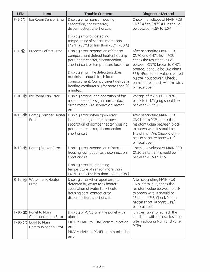
– 80 –
LED Item Trouble Contents Diagnostic MethodF-1- Ice Room Sensor Error Display error: sensor housing
separation, contact error, disconnection, short circuit
Display error by detecting temperature of sensor: more than 149°F (+65°C) or less than -58°F (-50°C)
Check the voltage of MAIN PCB CN32 #3 to CN75 #1. It should be between 4.5V to 1.0V.
F-1- Freezer Defrost Error Display error: separation of freezer compartment defrost heater housing part, contact error, disconnection, short circuit, or temperature fuse error
Display error: The defrosting does not fi nish through fresh food compartment. Compartment defrost is heating continuously for more than 70 minutes.
After separating MAIN PCB CN70 and CN71 from PCB, check the resistant value between CN70 brown to CN71 orange. It should be 102 ohms ±7%. (Resistance value is varied by the input power.) Check 0 ohm: heater short, ∞ ohm: wire/bimetal open.
F-10- Ice Room Fan Error Display error during operation of fan motor: feedback signal line contact error, motor wire separation, motor error
Voltage of MAIN PCB CN76 black to CN75 gray should be between 6V to 12V.
R-10- Pantry Damper Heater Error
Display error: when open error is detected by damper heater: separation of damper heater housing part, contact error, disconnection, short circuit
After separating MAIN PCB CN91 from PCB, check the resistant value between black to brown wire. It should be 145 ohms ±7%. Check 0 ohm: heater short, ∞ ohm: wire/bimetal open.
R-10- Pantry Sensor Error Display error: separation of sensor housing, contact error, disconnection, short circuit
Display error by detecting temperature of sensor: more than 149°F (+65°C) or less than -58°F (-50°C)
Check the voltage of MAIN PCB CN30 #8 to #9. It should be between 4.5V to 1.0V.
R-10- Water Tank Heater Error
Display error when open error is detected by water tank heater: separation of water tank heater housing part, contact error, disconnection, short circuit
After separating MAIN PCB CN78 from PCB, check the resistant value between black to brown wire. It should be 45 ohms ±7%. Check 0 ohm: heater short, ∞ ohm: wire/bimetal open.
F-10- Panel to Main Communication Error
Display of Pc/Lc Er in the panel with alarm: MICOM MAIN to LOAD communication errorMICOM MAIN to PANEL communication error
It is desirable to recheck the condition with the oscilloscope after replacing Main and Panel PCBs
F-10- Load to Main Communication Error
f
g
b
a
b
g
g
f

– 81 –
Sensor Resistance / Voltage Checks Table
°C °F Voltage Ohms °C °F Voltage Ohms °C °F Voltage Ohms
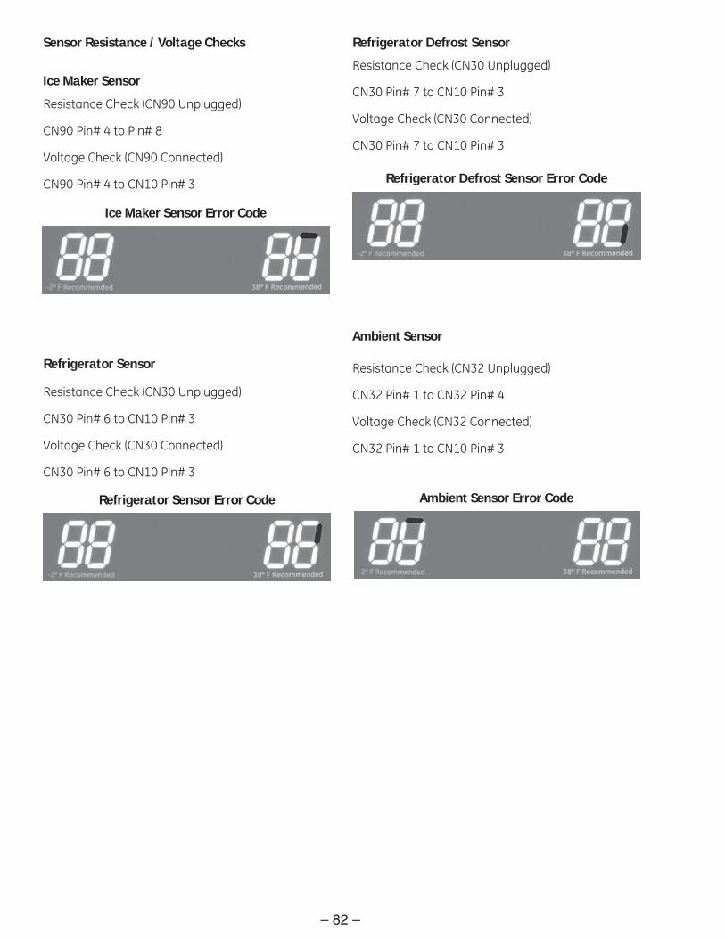
– 82 –
Sensor Resistance / Voltage Checks
Ice Maker Sensor
Resistance Check (CN90 Unplugged)
CN90 Pin# 4 to Pin# 8
Voltage Check (CN90 Connected)
CN90 Pin# 4 to CN10 Pin# 3
Refrigerator Sensor
Resistance Check (CN30 Unplugged)
CN30 Pin# 6 to CN10 Pin# 3
Voltage Check (CN30 Connected)
CN30 Pin# 6 to CN10 Pin# 3
Refrigerator Defrost Sensor
Resistance Check (CN30 Unplugged)
CN30 Pin# 7 to CN10 Pin# 3
Voltage Check (CN30 Connected)
CN30 Pin# 7 to CN10 Pin# 3
Ambient Sensor
Resistance Check (CN32 Unplugged)
CN32 Pin# 1 to CN32 Pin# 4
Voltage Check (CN32 Connected)
CN32 Pin# 1 to CN10 Pin# 3
Ice Maker Sensor Error Code
Refrigerator Sensor Error Code
Refrigerator Defrost Sensor Error Code
Ambient Sensor Error Code

– 83 –
Freezer Sensor
Resistance Check (CN30 Unplugged)
CN30 Pin# 3 to CN10 Pin# 3
Voltage Check (CN30 Connected)
CN30 Pin# 3 to CN10 Pin# 3
Freezer Defrost Sensor
Resistance Check (CN30 Unplugged)
CN30 Pin# 4 to CN10 Pin# 3
Voltage Check (CN32 Connected)
CN30 Pin# 4 to CN10 Pin# 3
Ice Room Sensor
Resistance Check (CN32 Unplugged)
CN32 Pin# 3 to CN10 Pin# 3
Voltage Check (CN32 Connected)
CN32 Pin# 3 to CN10 Pin# 3
Pantry Sensor
Resistance Check (CN30 Unplugged)
CN30 Pin# 8 to CN30 Pin# 9
Voltage Check (CN30 Connected)
CN30 Pin# 8 to CN10 Pin# 3
Freezer Sensor Error Code
Freezer Defrost Sensor Error Code
Ice Room Sensor Error Code
Pantry Sensor Error Code

– 84 –
Operational Fan Checks
Note: All fan voltage checks are from CN10 Pin# 3.
Check voltage to fans:
Freezer Fan – CN75 Pin#2 7 to 12 VDC
Refrigerator Fan – CN75 Pin#3 7 to 12 VDC
Condenser Fan – CN75 Pin#4 7 to 12 VDC
Check voltage from fans (indicates fans are turning):
Freezer Fan – CN75 Pin#5 2 to 3 VDC
Refrigerator Fan – CN75 Pin#6 2 to 3 VDC
Condenser Fan – CN75 Pin#7 2 to 3 VDC
GND
GND
GND
Freezer Fan Strip Circuit
Refrigerator Fan Strip Circuit
Condenser Fan Strip Circuit
Refrigerator Fan Error Code
Freezer Fan Error Code
Condenser Fan Error Code

– 85 –
Water Tank Heater
With CN78 unplugged from the board, read resistance between pins 4 and 5 of plug.
Heater should read approximately 48 ohms. When heater is energized, there should be approximately 12VDC between pins 4 and 5 of CN78. (Plug connected to board)
Ice Room Fan Checks
Note: All fan voltage checks are from CN10 Pin# 3
Check voltage to fan:
Ice Room Fan – CN76 Pin#1 7 to 12 VDC
Check voltage from fan (indicates fans are turning):
Ice Room Fan – CN76 Pin#2 2 to 3 VDC
Pantry Room Damper Heater
With CN91 unplugged from the board, read resistance between pins 1 and 2 of plug.
Heater should read approximately 145 ohms.
When the heater is energized, there should be approximately 12VDC between pins 1 and 2 of CN91. (Plug connected to board)
Ice Room Fan Error Code
Pantry Room Damper Heater Error Code
Water Tank Heater Error Code

– 86 –
Defrost Heaters
Freezer Defrost Heater
The Freezer Defrost Heater has a resistance value of approximately 56 Ω and is in a parallel circuit with the duct heater. (See Duct Heater.)
Disconnect CN70 from the board. Check for a combined resistance of 55 Ω between pin 9 to CN71 pin 9, when the defrost safety thermostat is closed. A reading of approximately 3.18K Ω will indicate an open freezer defrost heater, wiring, or connection.
Compressor
Note: There is a 5-minute delay start with a cold cabinet.
The compressor utilizes a “Switched Neutral” circuit. The L1 side is always “hot”.
Read between CN1 pin# 1 (L1) on power supply board to CN71 pin# 7. Test will show 120 VAC, if board wants compressor to run.
Refrigerator Defrost Heater Circuit
Freezer Defrost Heater Circuit Note: To functionally test the defrost heaters, energize the heaters by using the test mode. (See Test Mode Operation.)
Freezer Defrost Heater Error Code
Refrigerator Defrost Heater Error Code
Refrigerator Defrost Heater
With CN70 unplugged from the board, read resistance between pin 7 to CN71 pin 9. Refrigerator Defrost Heater should read approximately 120 ohms.
Compressor Circuit

– 87 –
Schematic
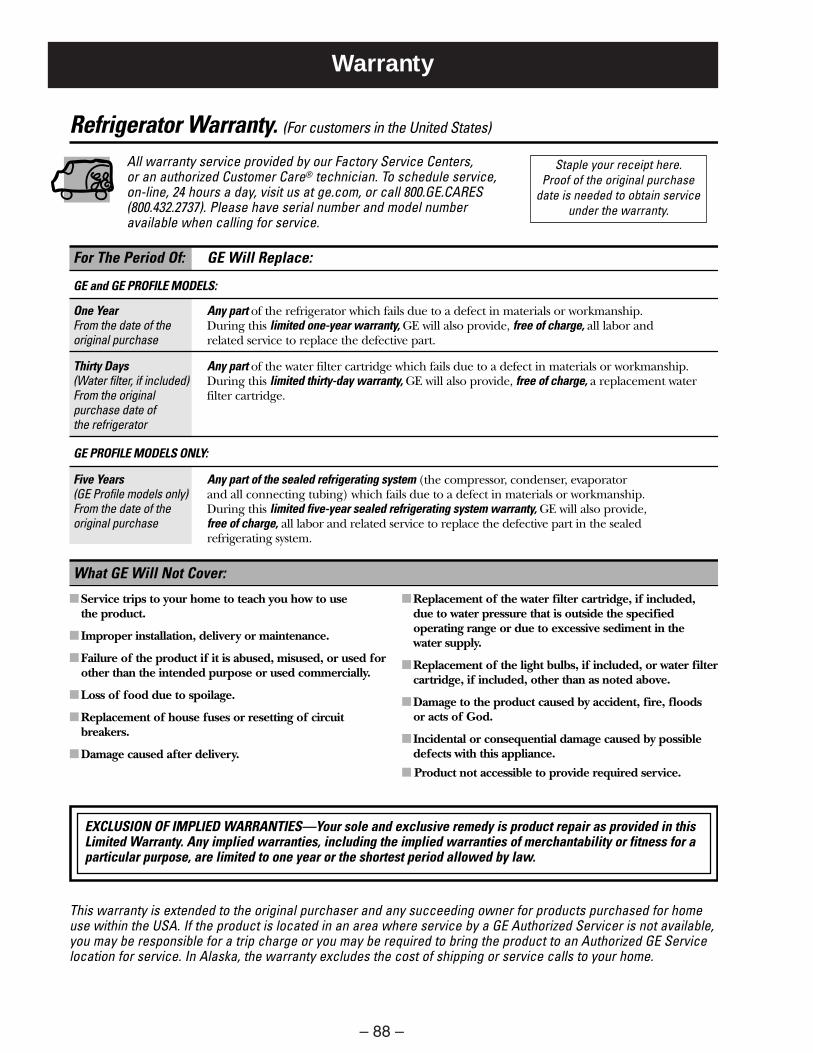
– 88 –
Warranty
Refrigerator Warranty. (For customers in the United States)
All warranty service provided by our Factory Service Centers, or an authorized Customer Care® technician. To schedule service, on-line, 24 hours a day, visit us at ge.com, or call 800.GE.CARES(800.432.2737). Please have serial number and model numberavailable when calling for service.
For The Period Of: GE Will Replace:
GE and GE PROFILE MODELS:
One Year Any part of the refrigerator which fails due to a defect in materials or workmanship.From the date of the During this limited one-year warranty, GE will also provide, free of charge, all labor and original purchase related service to replace the defective part.
Thirty Days Any part of the water filter cartridge which fails due to a defect in materials or workmanship.(Water filter, if included) During this limited thirty-day warranty, GE will also provide, free of charge, a replacement waterFrom the original filter cartridge.purchase date of the refrigerator
GE PROFILE MODELS ONLY:
Five Years Any part of the sealed refrigerating system (the compressor, condenser, evaporator (GE Profile models only) and all connecting tubing) which fails due to a defect in materials or workmanship.From the date of the During this limited five-year sealed refrigerating system warranty, GE will also provide, original purchase free of charge, all labor and related service to replace the defective part in the sealed
refrigerating system.
■ Service trips to your home to teach you how to use the product.
■ Improper installation, delivery or maintenance.
■ Failure of the product if it is abused, misused, or used forother than the intended purpose or used commercially.
■ Loss of food due to spoilage.
■ Replacement of house fuses or resetting of circuitbreakers.
■ Damage caused after delivery.
■ Replacement of the water filter cartridge, if included,due to water pressure that is outside the specifiedoperating range or due to excessive sediment in the water supply.
■ Replacement of the light bulbs, if included, or water filtercartridge, if included, other than as noted above.
■ Damage to the product caused by accident, fire, floods or acts of God.
■ Incidental or consequential damage caused by possibledefects with this appliance.
■ Product not accessible to provide required service.
What GE Will Not Cover:
This warranty is extended to the original purchaser and any succeeding owner for products purchased for homeuse within the USA. If the product is located in an area where service by a GE Authorized Servicer is not available,you may be responsible for a trip charge or you may be required to bring the product to an Authorized GE Servicelocation for service. In Alaska, the warranty excludes the cost of shipping or service calls to your home.
Staple your receipt here. Proof of the original purchase
date is needed to obtain serviceunder the warranty.
EXCLUSION OF IMPLIED WARRANTIES—Your sole and exclusive remedy is product repair as provided in thisLimited Warranty. Any implied warranties, including the implied warranties of merchantability or fitness for aparticular purpose, are limited to one year or the shortest period allowed by law.

– 89 –
TERMS AND CONDITIONS:This warranty applies only for single family domestic use inCanada when the Refrigerator has been properly installedaccording to the instructions supplied by Mabe and isconnected to an adequate and proper utility service.Damage due to abuse, accident, commercial use, and alterationor defacing of the serial plate cancels all obligations of thiswarranty.Service during this warranty period must be performed by anAuthorized Mabe Service Agent.
Neither Mabe nor the Dealer is liable for any claims ordamages resulting from failure of the Refrigerator or fromservice delays beyond their reasonable control.
To obtain warranty service, purchaser must present the originalBill of Sale. Components repaired or replaced are warrantedthrough the remainder of the original warranty period only.
This warranty is extended to the original purchaser and anysucceeding owner for products purchased for home use withinCanada. In home warranty service will be provided in areaswhere it is available and deemed reasonable by Mabe to provide.
This warranty is in addition to any statutory warranty.
WHAT IS NOT COVERED:• Owner is responsible to pay for service calls related to
product installation and/or teaching how to use the product.
• Damage to finish must be reported within 48 hours followingthe delivery of the appliance.
• Damage to finish after delivery.• Improper installation—proper installation includes adequate
air circulation to the refrigeration system, adequate electrical,plumbing and other connecting facilities.
• Replacement of house fuses or resetting of circuit breakers.• Replacement of light bulbs.• Damage to product caused by accident, fire, floods or acts
of God.• Loss of food due to spoilage.• Proper use and care of product as listed in the owner’s
manual, proper setting of controls.• Product not accessible to provide required service.• WARRANTOR IS NOT RESPONSIBLE FOR CONSEQUENTIAL
DAMAGES.
IMPORTANTKeep this warranty and your bill of sale as proof of original purchase and purchase date. Please have serial number and model number available when calling for service.
Mabe Service is available coast to coast. If further help is needed concerning this warranty, contact:
Manager, Consumer RelationsMabe Canada Inc., Consumer Service1 Factory Lane, Suite 310Moncton, New Brunswick E1C 9M31.800.561.3344
Staple your receipt here. Proof of the original purchase
date is needed to obtain serviceunder the warranty.
What is covered How Long Warranted Parts Labour(From Date of Sale) Repair or Replace
at Mabe’s Option
Compressor GE Profile: Ten (10) Years GE Profile: Ten (10) Years GE Profile: Five (5) YearsGE and All Other GE and All Other GE and All Other
Brands: One (1) Year Brands: One (1) Year Brands: One (1) Year
Sealed System (including GE Profile: Five (5) Years GE Profile: Five (5) Years GE Profile: Five (5) Yearsevaporator, condenser GE and All Other GE and All Other GE and All Othertubing and refrigerant) Brands: One (1) Year Brands: One (1) Year Brands: One (1) Year
All Other Parts One (1) Year One (1) Year One (1) Year
CUSTOMER WARRANTY(for customers in Canada)
Your refrigerator is warranted to be free of defects in material and workmanship.
EXCLUSION OF IMPLIED WARRANTIES—Your sole and exclusive remedy is product repair as provided in this LimitedWarranty. Any implied warranties, including the implied warranties of merchantability or fitness for a particular purpose,are limited to one year or the shortest period allowed by law.