Embed Size (px)
Citation preview
Gas Flotation Technology
C. TyrieJ.M. Walsh

The term “Gas Flotation” is sometimes used as if it is one technology.
It is not.
There is a wide range of flotation technologies available today. Some have 95 % separation efficiency, but are large and heavy,
others have 50 % separation efficiency but are compact. Others have 30 % separation efficiency but are inexpensive.
Our goal in this paper is to provide some guidance in selecting the most appropriate flotation technology for a given
application.
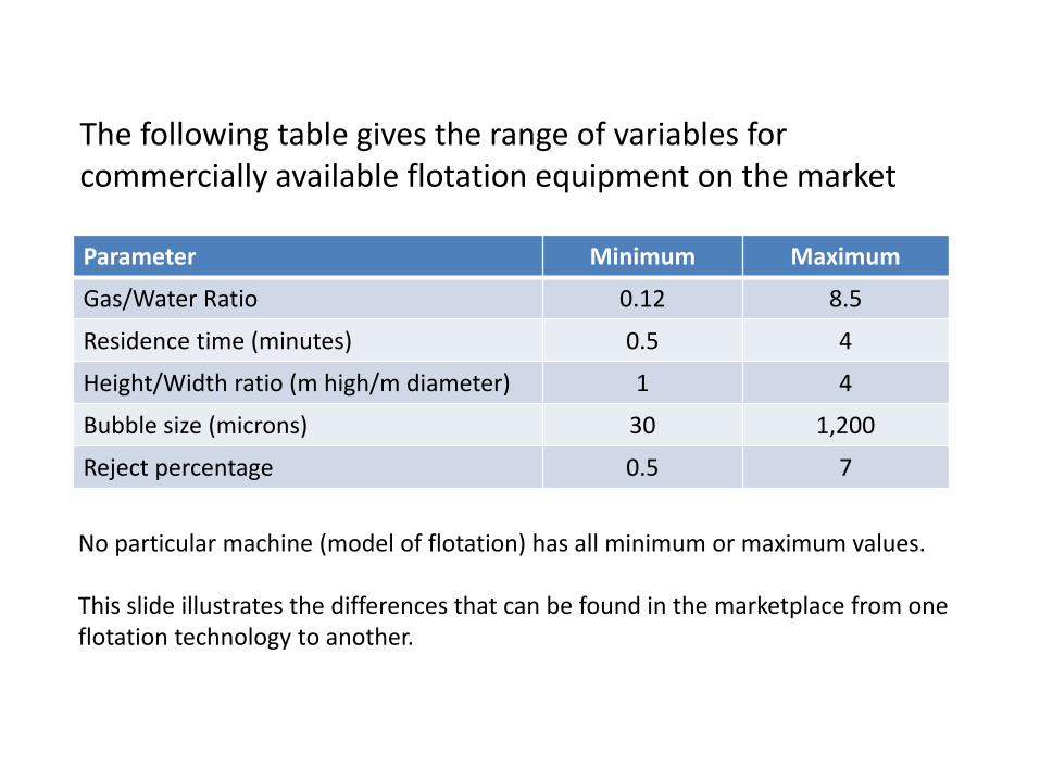
The following table gives the range of variables for commercially available flotation equipment on the market
Parameter Minimum Maximum
Gas/Water Ratio 0.12 8.5
Residence time (minutes) 0.5 4
Height/Width ratio (m high/m diameter) 1 4
Bubble size (microns) 30 1,200
Reject percentage 0.5 7
No particular machine (model of flotation) has all minimum or maximum values.
This slide illustrates the differences that can be found in the marketplace from one flotation technology to another.
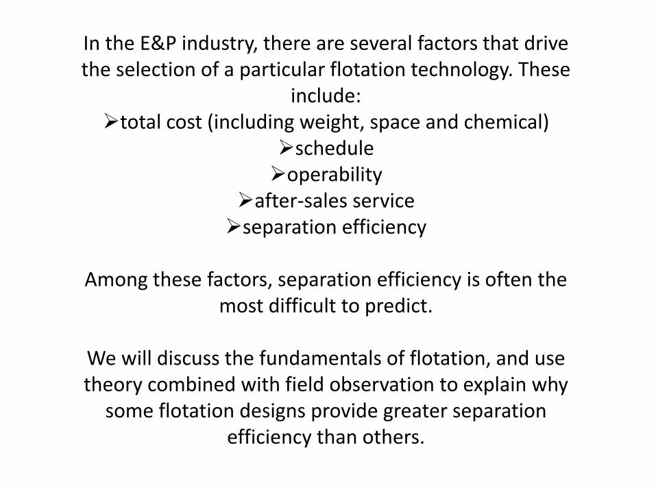
In the E&P industry, there are several factors that drive the selection of a particular flotation technology. These
include:total cost (including weight, space and chemical)
scheduleoperability
after-sales serviceseparation efficiency
Among these factors, separation efficiency is often the most difficult to predict.
We will discuss the fundamentals of flotation, and use theory combined with field observation to explain why
some flotation designs provide greater separation efficiency than others.
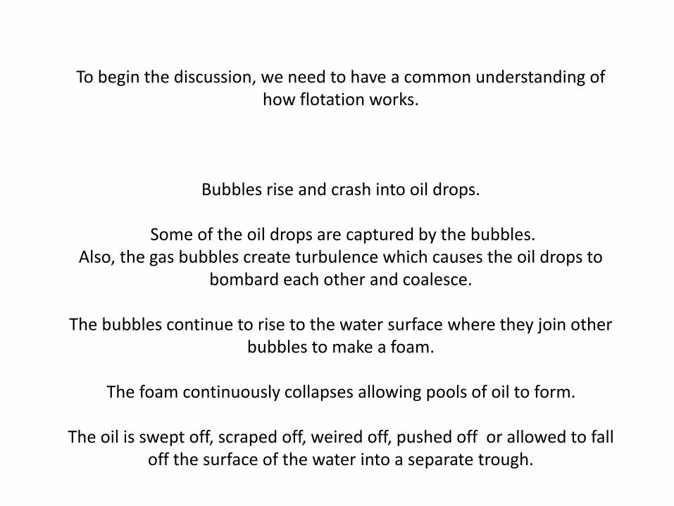
To begin the discussion, we need to have a common understanding of how flotation works.
Bubbles rise and crash into oil drops.
Some of the oil drops are captured by the bubbles.Also, the gas bubbles create turbulence which causes the oil drops to
bombard each other and coalesce.
The bubbles continue to rise to the water surface where they join other bubbles to make a foam.
The foam continuously collapses allowing pools of oil to form.
The oil is swept off, scraped off, weired off, pushed off or allowed to fall off the surface of the water into a separate trough.
Gas Flotation - Fundamentals
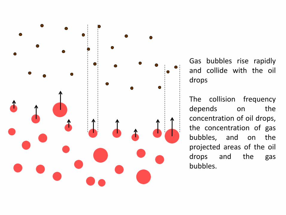
Gas bubbles rise rapidlyand collide with the oildrops
The collision frequencydepends on theconcentration of oil drops,the concentration of gasbubbles, and on theprojected areas of the oildrops and the gasbubbles.
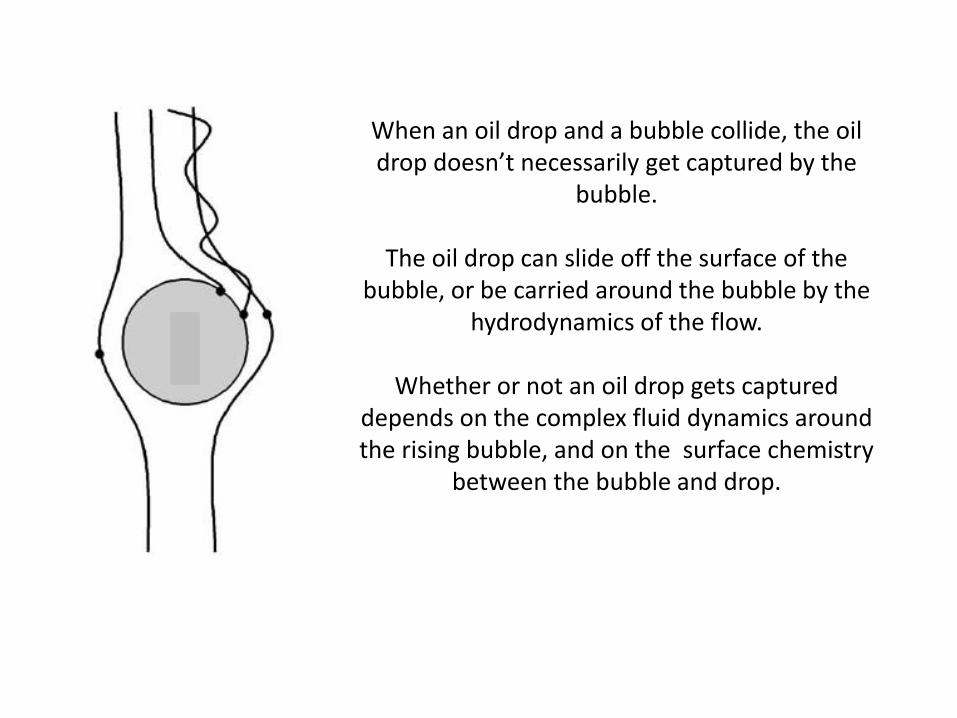
When an oil drop and a bubble collide, the oil drop doesn’t necessarily get captured by the
bubble.
The oil drop can slide off the surface of the bubble, or be carried around the bubble by the
hydrodynamics of the flow.
Whether or not an oil drop gets captured depends on the complex fluid dynamics around the rising bubble, and on the surface chemistry
between the bubble and drop.
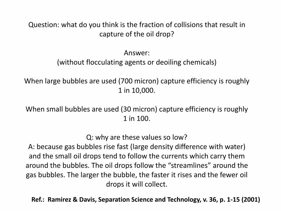
Question: what do you think is the fraction of collisions that result in capture of the oil drop?
Answer:(without flocculating agents or deoiling chemicals)
When large bubbles are used (700 micron) capture efficiency is roughly 1 in 10,000.
When small bubbles are used (30 micron) capture efficiency is roughly 1 in 100.
Q: why are these values so low?A: because gas bubbles rise fast (large density difference with water) and the small oil drops tend to follow the currents which carry them
around the bubbles. The oil drops follow the “streamlines” around the gas bubbles. The larger the bubble, the faster it rises and the fewer oil
drops it will collect.
Ref.: Ramirez & Davis, Separation Science and Technology, v. 36, p. 1-15 (2001)
1.00E-05
1.00E-04
1.00E-03
1.00E-02
1.00E-01
1.00E+00
0 500 1000 1500 2000
Cap
ture
Eff
icie
ncy
(ca
ptu
res/
colli
sio
n)
bubble diameter (microns)
without chemical
with chemical
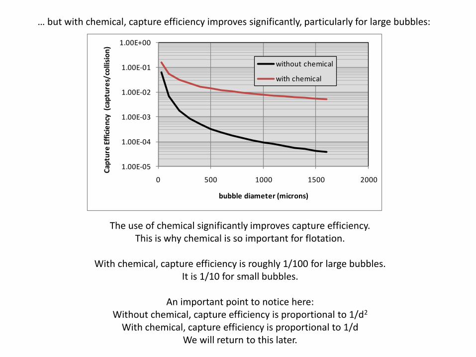
… but with chemical, capture efficiency improves significantly, particularly for large bubbles:
The use of chemical significantly improves capture efficiency.This is why chemical is so important for flotation.
With chemical, capture efficiency is roughly 1/100 for large bubbles.It is 1/10 for small bubbles.
An important point to notice here:Without chemical, capture efficiency is proportional to 1/d2
With chemical, capture efficiency is proportional to 1/dWe will return to this later.
Stokes law which shows that the smaller bubble rises much slower than the bigger bubble.
Hence there is a certain number which we call the small bubble, iefor DGF pumps we can look at 60/80 micron whereas the old wemco
is 140 micron.
That is why the wemco is more efficient when the inlet is 200ppm plus but droips at a lower ppm because the oil droplet is smaller.
Besides chemical, a bit of turbulence improves the capture efficiency.
Turbulence makes the trajectory of the oil drop and gas bubble more random and hence the oil drops deviate from the
hydrodynamic streamlines.
Large bubbles create more turbulence.
Rotating paddles also create turbulence.
Swirl motion increases the retention time.
Internal baffles force oil and gas bubbles to collide in a small cross sectional area.
Coalescing elements provide surface area for coalescence.
Other Factors:
Besides capture efficiency, the number of collisions is important as well.
But how important?
The more gas that is used, of course, the more bubbles are generated. The more bubbles, the more collisions there are
between bubbles and oil drops.
The more collisions there are, the more oil drops that are captured.
But, the more gas that is used, the more expensive (generally).Flotation using the DGF pump (Siemens, GLR and Edur) are generally cheaper than Wemco’s and their copies but they
deliver much less gas. For the same amount of gas, they are more expensive.
Can we quantify this (as we did for capture efficiency)?
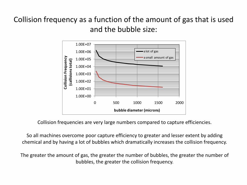
Collision frequency as a function of the amount of gas that is used and the bubble size:
Collision frequencies are very large numbers compared to capture efficiencies.
So all machines overcome poor capture efficiency to greater and lesser extent by adding chemical and by having a lot of bubbles which dramatically increases the collision frequency.
The greater the amount of gas, the greater the number of bubbles, the greater the number of bubbles, the greater the collision frequency.
1.00E+00
1.00E+01
1.00E+02
1.00E+03
1.00E+04
1.00E+05
1.00E+06
1.00E+07
0 500 1000 1500 2000
Co
llisi
on
Fre
qu
ency
(cal
lisio
ns
tota
l)
bubble diameter (microns)
a lot of gas
a small amount of gas
Gas Flotation - Fundamentals
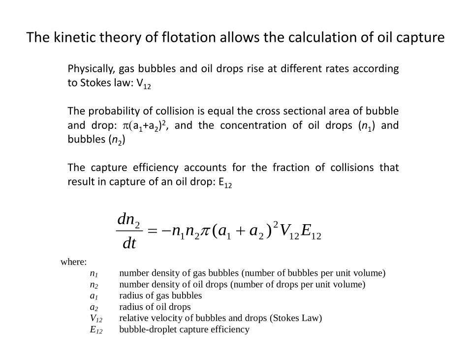
Physically, gas bubbles and oil drops rise at different rates accordingto Stokes law: V12
The probability of collision is equal the cross sectional area of bubbleand drop: p(a1+a2)2, and the concentration of oil drops (n1) andbubbles (n2)
The capture efficiency accounts for the fraction of collisions thatresult in capture of an oil drop: E12
1212
2
21212 )( EVaann
dt
dn p
where:
n1 number density of gas bubbles (number of bubbles per unit volume)
n2 number density of oil drops (number of drops per unit volume)
a1 radius of gas bubbles
a2 radius of oil drops
V12 relative velocity of bubbles and drops (Stokes Law)
E12 bubble-droplet capture efficiency
The kinetic theory of flotation allows the calculation of oil capture
Gas Flotation - Fundamentals
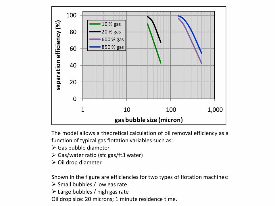
The model allows a theoretical calculation of oil removal efficiency as afunction of typical gas flotation variables such as: Gas bubble diameter Gas/water ratio (sfc gas/ft3 water) Oil drop diameter
Shown in the figure are efficiencies for two types of flotation machines: Small bubbles / low gas rate Large bubbles / high gas rateOil drop size: 20 microns; 1 minute residence time.
0
20
40
60
80
100
1 10 100 1,000
sep
arat
ion
eff
icie
ncy
(%)
gas bubble size (micron)
10 % gas
20 % gas
600 % gas
850 % gas
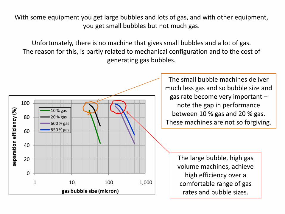
With some equipment you get large bubbles and lots of gas, and with other equipment, you get small bubbles but not much gas.
Unfortunately, there is no machine that gives small bubbles and a lot of gas.The reason for this, is partly related to mechanical configuration and to the cost of
generating gas bubbles.
0
20
40
60
80
100
1 10 100 1,000
sep
arat
ion
eff
icie
ncy
(%)
gas bubble size (micron)
10 % gas
20 % gas
600 % gas
850 % gas
The large bubble, high gas volume machines, achieve
high efficiency over a comfortable range of gas rates and bubble sizes.
The small bubble machines deliver much less gas and so bubble size and
gas rate become very important –note the gap in performance
between 10 % gas and 20 % gas. These machines are not so forgiving.
A summary of what we have discussed so far:
Collision Frequency: Collision frequency increases as gas flow rate increases because more gas means more bubbles.
Collision frequency increases as bubble size decreases because the number of bubbles increases as the bubble size decreases,
Capture Efficiency: Capture efficiency increases as the bubble size decreases because larger bubbles move too fast to capture the slow moving oil drops. But this
effect is less pronounced when chemical is added.
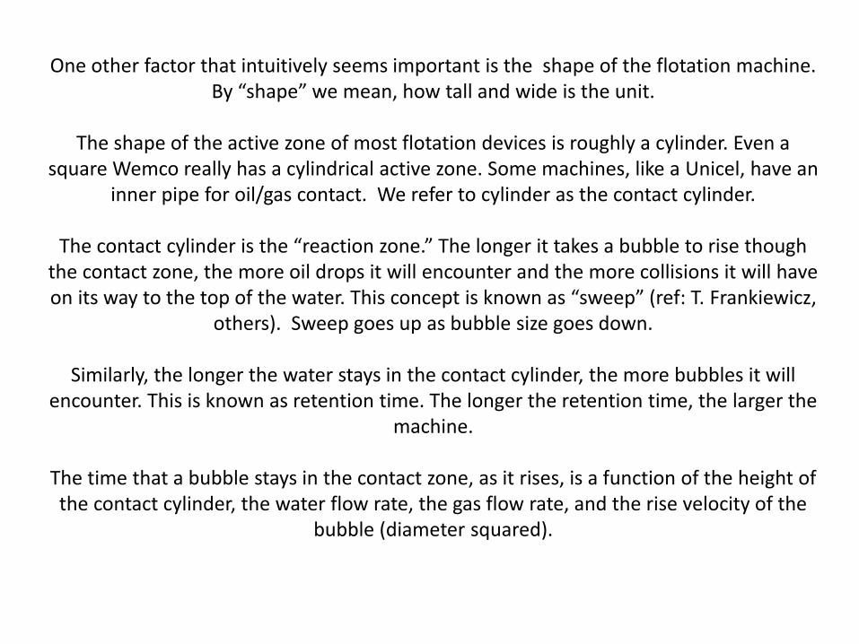
One other factor that intuitively seems important is the shape of the flotation machine.By “shape” we mean, how tall and wide is the unit.
The shape of the active zone of most flotation devices is roughly a cylinder. Even a square Wemco really has a cylindrical active zone. Some machines, like a Unicel, have an
inner pipe for oil/gas contact. We refer to cylinder as the contact cylinder.
The contact cylinder is the “reaction zone.” The longer it takes a bubble to rise though the contact zone, the more oil drops it will encounter and the more collisions it will have on its way to the top of the water. This concept is known as “sweep” (ref: T. Frankiewicz,
others). Sweep goes up as bubble size goes down.
Similarly, the longer the water stays in the contact cylinder, the more bubbles it will encounter. This is known as retention time. The longer the retention time, the larger the
machine.
The time that a bubble stays in the contact zone, as it rises, is a function of the height of the contact cylinder, the water flow rate, the gas flow rate, and the rise velocity of the
bubble (diameter squared).
Gas Flotation - Fundamentals
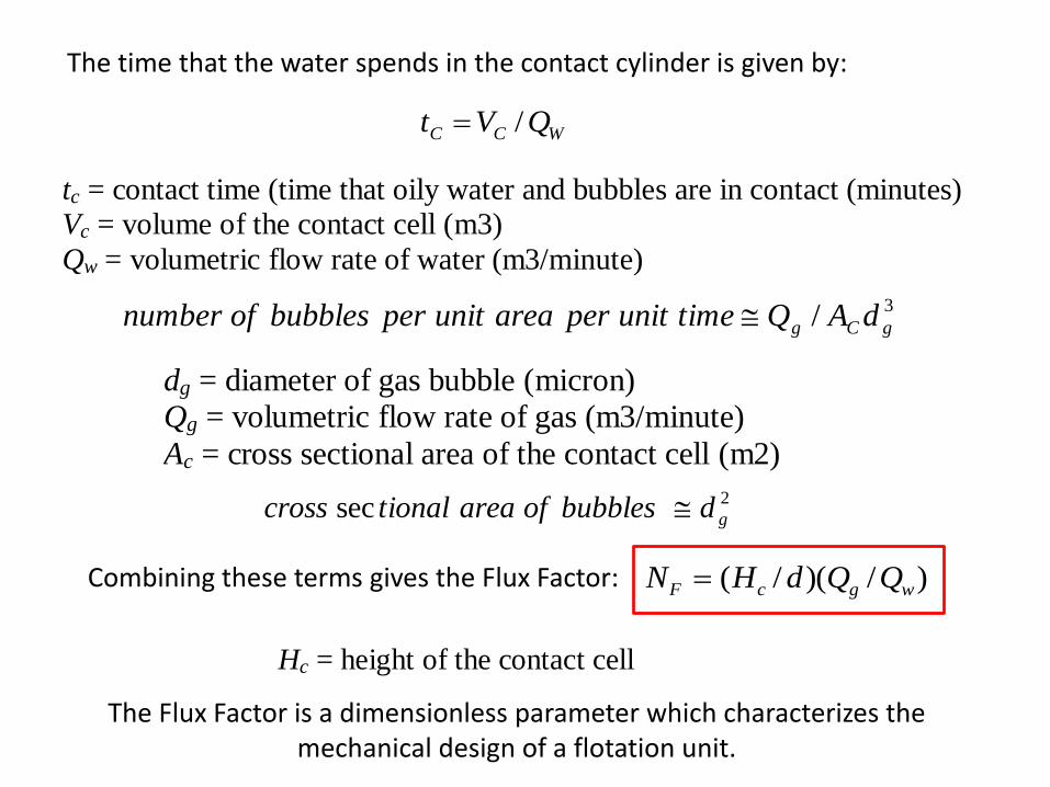
The time that the water spends in the contact cylinder is given by:
tc = contact time (time that oily water and bubbles are in contact (minutes)
Vc = volume of the contact cell (m3)
Qw = volumetric flow rate of water (m3/minute)
WCC QVt /
3/ gCg dAQtimeunitperareaunitperbubblesofnumber
dg = diameter of gas bubble (micron)
Qg = volumetric flow rate of gas (m3/minute)
Ac = cross sectional area of the contact cell (m2)
2sec gdbubblesofareationalcross
Combining these terms gives the Flux Factor: )/)(/( wgcF QQdHN Vc = volume of the cylindrical contact cell
Ac = cross sectional area of the contact cell
Hc = height of the contact cell
The Flux Factor is a dimensionless parameter which characterizes the mechanical design of a flotation unit.
In the material below, the Flux Factor is correlated with field observations of the separation efficiency.
This correlation will help us decide:
Should we buy a machine with long residence time, which may cost more? Or can we buy a less expensive machine that has a tall and narrow contact cylinder?
Is it worthwhile to invest in a machine that can generate a lot of gas? We know this is good, but again it is also more expensive. Also, it is more dependent on chemical selection and dosage.
Should we invest in a machine with small bubbles? They seem to do a better job capturing small oil drops, but they are limited in the amount of gas and hence in the number of collisions.
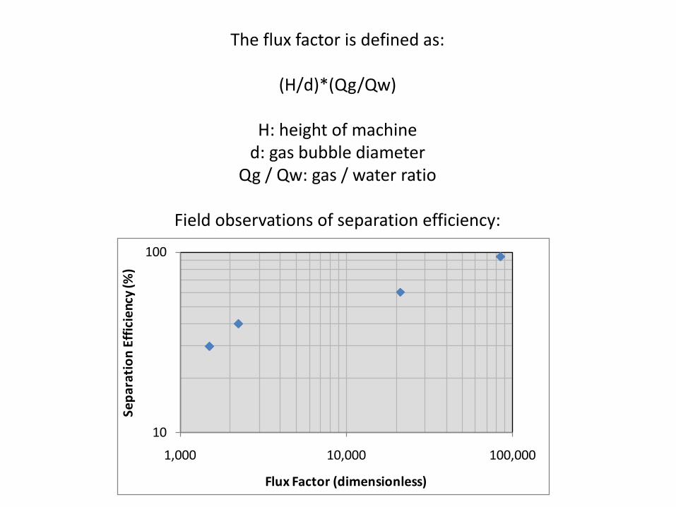
The flux factor is defined as:
(H/d)*(Qg/Qw)
H: height of machined: gas bubble diameter
Qg / Qw: gas / water ratio
Field observations of separation efficiency:
10
100
1,000 10,000 100,000
Sep
arat
ion
Eff
icie
ncy
(%)
Flux Factor (dimensionless)
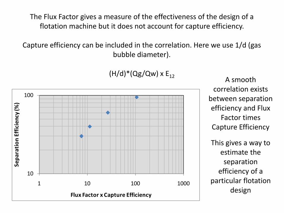
The Flux Factor gives a measure of the effectiveness of the design of a flotation machine but it does not account for capture efficiency.
Capture efficiency can be included in the correlation. Here we use 1/d (gas bubble diameter).
(H/d)*(Qg/Qw) x E12
10
100
1 10 100 1000
Sep
arat
ion
Eff
icie
ncy
(%)
Flux Factor x Capture Efficiency
A smooth correlation exists
between separation efficiency and Flux
Factor times Capture Efficiency
This gives a way to estimate the separation
efficiency of a particular flotation
design
The discussion presented here is useful for judging the design of one flotation unit versus another.
A good correlation was found between separation efficiency and Flux Factor times Capture Efficiency.
In the data shown, chemical was used.
Other factors are also important such as oil drop size, presence of coalescing elements or internal baffles, etc. These are not accounted for.
We do not wish to show which vendors give which results – call us to discuss.
... except to say that the horizontal, multi-stage IGF gives the highest Flux Factor and gives the highest separation efficiency, despite having large gas
bubble diameters. The large volume of gas and the multistage effect (J. Chen et al.) overcomes the detrimental effects of large bubbles.