Embed Size (px)
Citation preview
Please leave these instructions with the user
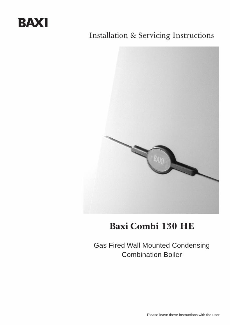
Baxi Combi 130 HE
Gas Fired Wall Mounted CondensingCombination Boiler
Installation & Servicing Instructions
2
Baxi is one of the leading manufacturers of domestic
heating products in the UK.
Our first priority is to give a high quality service to our
customers. Quality is designed into every Baxi product
- products which fulfil the demands and needs of
customers, offering choice, efficiency and reliability.
To keep ahead of changing trends, we have made a
commitment to develop new ideas using the
latest technology - with the aim of continuing to make
the products that customers want to buy.
Everyone who works at Baxi has a commitment to
quality because we know that satisfied customers
mean continued success.
We hope you get a satisfactory service from Baxi. If
not, please let us know.
Natural Gas
Baxi Combi 130 HEG.C.No 47 075 04
Baxi is a BS-EN ISO 9001 Accredited Company
The boiler meets the requirements of Statutory Instrument“ The Boiler (Efficiency) Regulations 1993 No 3083” and isdeemed to meet the requirements of Directive 92/42/EECon the energy efficiency requirements for new hot waterboilers fired with liquid or gaseous fuels:-
Type test for purpose of Regulation 5 certified by: Notified Body 0086.
Product/Production certified by:Notified Body 0086.Ref: 86-BL-647
For GB/IE only.
3
0.0 Legislation 4
1.0 Introduction 5
2.0 General Layout 6
3.0 Appliance Operation 7
4.0 Technical Data 8
5.0 Dimensions and Fixings 9
6.0 System Details 10
7.0 Site Requirements 13
8.0 Installation 19
9.0 Electrical 26
10.0 Commissioning the Boiler 28
11.0 Fitting the Outer Case 32
12.0 Servicing the Boiler 33
13.0 Changing Components 35
14.0 Short Parts List 46
15.0 Fault Finding 47
16.0 Operational Flow Chart 58
Section Page
Contents
0.0 Legislation
4
Baxi declare that no substances harmful to
health are contained in the appliance or used
during appliance manufacture.
The appliance is suitable only for installation inGB and IE and should be installed in accordancewith the rules in force, and only used in a suitablyventilated location.
In GB, the installation must be carried out by aCORGI Registered Installer. It must be carried out inaccordance with the relevant requirements of the:• Gas Safety (Installation & Use) Regulations.• The appropriate Building Regulations either The
Building Regulations, The Building Regulations (Scotland), Building Regulations (Northern Ireland).
• The Water Fittings Regulations or Water Byelaws in Scotland.
• The Current I.E.E. Wiring Regulations.
Where no specific instructions are given, referenceshould be made to the relevant British Standard Codeof Practice.
In IE, the installation must be carried out by acompetent person and installed in accordance withthe current edition of I.S. 813 ‘Domestic GasInstallations’, the current Building Regulations andreference should be made to the current ETCI rulesfor electrical installation.
All systems must be thoroughly flushed andtreated with inhibitor (see section 6.0).
IMPORTANT - Installation, Commissioning, Service & Repair
This appliance must be installed in accordance with the manufacturer’sinstructions and the regulations in force. Read the instructions fully beforeinstalling or using the appliance.
In GB, this must be carried out by a competent person as stated in the GasSafety (Installation & Use) Regulations.
Definition of competence: A person who works for a CORGI registeredcompany and holding current certificates in the relevant ACS modules, orvalid ACoP equivalents, is deemed competent.
In IE, this must be carried out by a competent person as stated in I.S. 813“Domestic Gas Installations”.
Lifting - This product should be lifted and handled by two people. Stoopingshould be avoided and protective equipment worn where necessary. Carrying& lifting equipment should be used as required.
The addition of anything that may interfere with the normal operation of theappliance without express written permission from the manufacturer or hisagent could invalidate the appliance warranty. In GB this could also infringethe Gas Safety (Installation and Use) Regulations.
Warning - Check the information on the data plate is compatible with localsupply conditions.
“Benchmark” Installation, Commissioning and Service Record Log Book
Please ensure that your installer has completed the Installation andCommissioning sections of the Log Book and hands the Log Book over. Thedetails of the Log Book will be required in the event of any warranty work.Keep the Log Book in a safe place and ensure that the relevant sections arecompleted at each subsequent regular service visit.
All CORGI registered installers carry a CORGI identification card and have aregistration number. Both should be recorded in your boiler Log Book. Youcan check your installer is registered by telephoning +44 (0)1256 372300 orwriting to:-
1 Elmwood,Chineham Business Park,
Crockford Lane,Basingstoke. RG24 8WG
Codes of Practice, most recent version shouldbe used
In GB the following Codes of Practice apply:Standard ScopeBS 6891 Gas Installation.BS 5546 Installation of hot water supplies for
domestic purposes.BS 5449 Forced circulation hot water systems.BS 6798 Installation of gas fired hot water boilers.BS 5440 Part 1 Flues.BS 5440 Part 2 Ventilation.BS 7074 Expansion vessels and ancillary equipment
for sealed water systems.BS 7593 Treatment of water in domestic hot water
central heating systems.
In IE the following Codes of Practice apply:Standard ScopeI.S. 813 Domestic Gas Installations.The following BS standards give valuable additional information;BS 5546 Installation of hot water supplies for
domestic purposes.BS 5449 Forced circulation hot water systems.BS 7074 Expansion vessels and ancillary equipment
for sealed water systems.BS 7593 Treatment of water in domestic hot water
central heating systems.
This boiler is fitted with a flow switchinterlock that prevents it from firing whenthe heating demand is satisfied.
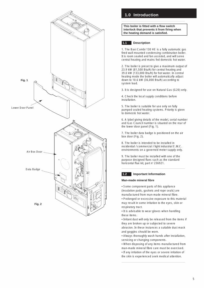
1.1 Description
1. The Baxi Combi 130 HE is a fully automatic gasfired wall mounted condensing combination boiler.It is room sealed and fan assisted, and will servecentral heating and mains fed domestic hot water.
2. The boiler is preset to give a maximum output of23.9 kW (81,500 Btu/h) for central heating and39.0 kW (133,000 Btu/h) for hot water. In centralheating mode the boiler will automatically adjustdown to 10.6 kW (36,000 Btu/h) according tosystem load.
3. It is designed for use on Natural Gas (G20) only.
4. Check the local supply conditions beforeinstallation.
5. The boiler is suitable for use only on fullypumped sealed heating systems. Priority is givento domestic hot water.
6. A label giving details of the model, serial numberand Gas Council number is situated on the rear ofthe lower door panel (Fig. 1).
7. The boiler data badge is positioned on the airbox door (Fig. 2).
8. The boiler is intended to be installed inresidential / commercial / light industrial E.M.C.environments on a governed meter supply only.
9. The boiler must be installed with one of thepurpose designed flues such as the standardhorizontal flue kit, part no 236921.
1.2 Important Information
Man-made mineral fibre
• Some component parts of this appliance(insulation pads, gaskets and rope seals) aremanufactured from man-made mineral fibre. • Prolonged or excessive exposure to this materialmay result in some irritation to the eyes, skin orrespiratory tract. • It is advisable to wear gloves when handlingthese items. • Irritant dust will only be released from the items ifthey are broken up or subjected to severeabrasion. In these instances a suitable dust maskand goggles should be worn.• Always thoroughly wash hands after installation,servicing or changing components. • When disposing of any items manufactured fromman-made mineral fibre care must be exercised.• If any irritation of the eyes or severe irritation ofthe skin is experienced seek medical attention.
1.0 Introduction
5
Fig. 1
Fig. 2
Lower Door Panel
Air Box Door
Data Badge
2.0 General Layout
6
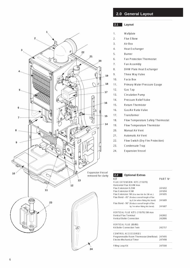
2.1 Layout
1. Wallplate
2. Flue Elbow
3. Air Box
4. Heat Exchanger
5. Burner
6. Fan Protection Thermostat
7. Fan Assembly
8. DHW Plate Heat Exchanger
9. Three Way Valve
10. Facia Box
11. Primary Water Pressure Gauge
12. Gas Tap
13. Circulation Pump
14. Pressure Relief Valve
15. Return Thermistor
16. Gas/Air Ratio Valve
17. Transformer
18. Flow Temperature Safety Thermostat
19. Flow Temperature Thermistor
20. Manual Air Vent
21. Automatic Air Vent
22. Flow Switch (Dry Fire Protection)
23. Condensate Trap
24. Expansion Vessel
2.2 Optional ExtrasKIT PART No
FLUE EXTENSION KITS (110/70)Horizontal Flue Kit 4M maxFlue Extension 0.25M 241692Flue Extension 0.5M 241694Flue Extension 1M (Use two kits for 2M etc.) 241695Flue Bend - 45° (Reduce overall length of flue
by 0.5m when fitting this bend) 241689Flue Bend - 90° (Reduce overall length of flue
by 1m when fitting this bend) 241687
VERTICAL FLUE KITS (110/70) 5M maxVertical Flue Terminal 242802Vertical Boiler Connection 242886
VERTICAL FLUE (80/80)Kit Boiler Connection Twin 242757
CONTROL ACCESSORIESProgrammable Room Thermostat (Intellistat) 247495Electro-Mechanical Timer 247498
Filling Loop Kit 247500
1
2
4
5
3
6
7
23
12
16
17
10
22
13
21
20
14
11
24
8
9
15
Expansion Vesselremoved for clarity
18
19
3.0 Appliance Operation
7
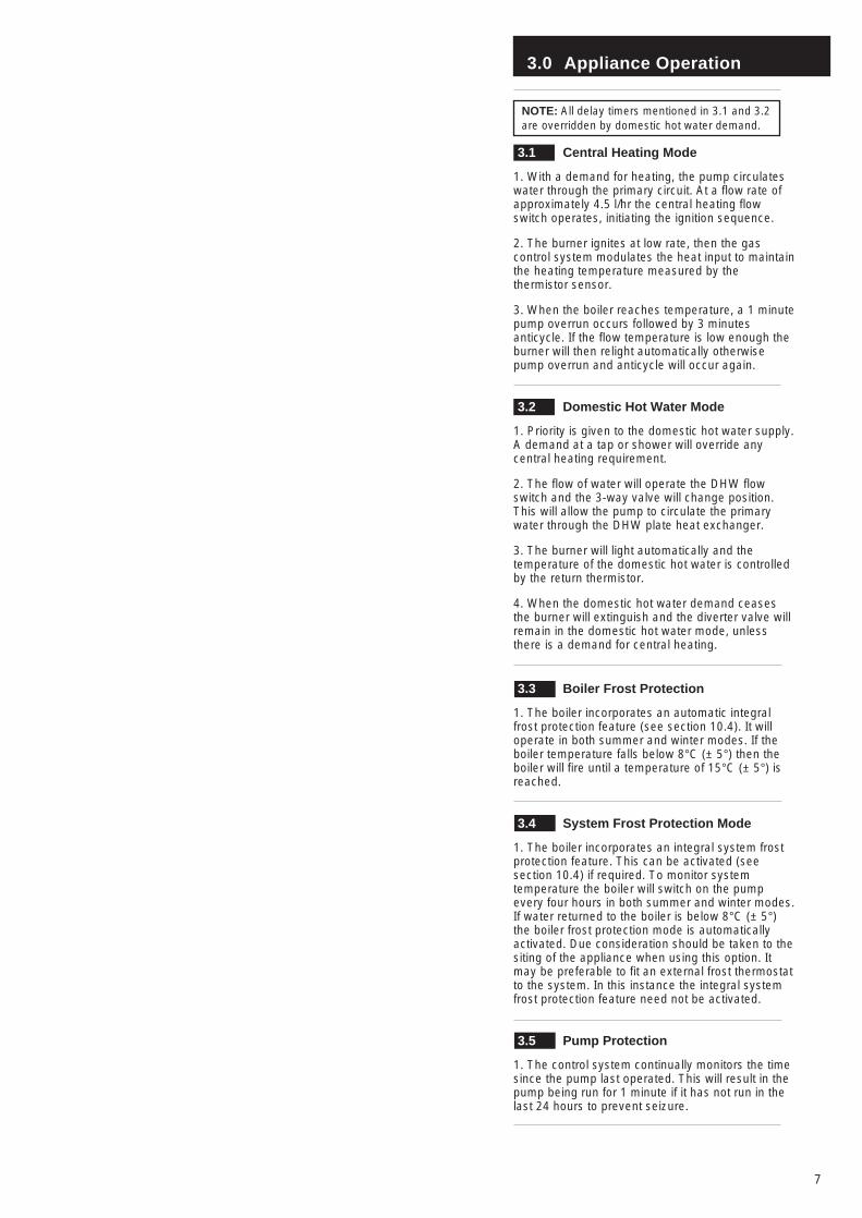
NOTE: All delay timers mentioned in 3.1 and 3.2are overridden by domestic hot water demand.
3.1 Central Heating Mode
1. With a demand for heating, the pump circulateswater through the primary circuit. At a flow rate ofapproximately 4.5 l/hr the central heating flowswitch operates, initiating the ignition sequence.
2. The burner ignites at low rate, then the gascontrol system modulates the heat input to maintainthe heating temperature measured by thethermistor sensor.
3. When the boiler reaches temperature, a 1 minutepump overrun occurs followed by 3 minutesanticycle. If the flow temperature is low enough theburner will then relight automatically otherwisepump overrun and anticycle will occur again.
3.2 Domestic Hot Water Mode
1. Priority is given to the domestic hot water supply.A demand at a tap or shower will override anycentral heating requirement.
2. The flow of water will operate the DHW flowswitch and the 3-way valve will change position.This will allow the pump to circulate the primarywater through the DHW plate heat exchanger.
3. The burner will light automatically and thetemperature of the domestic hot water is controlledby the return thermistor.
4. When the domestic hot water demand ceasesthe burner will extinguish and the diverter valve willremain in the domestic hot water mode, unlessthere is a demand for central heating.
3.3 Boiler Frost Protection
1. The boiler incorporates an automatic integralfrost protection feature (see section 10.4). It willoperate in both summer and winter modes. If theboiler temperature falls below 8°C (± 5°) then theboiler will fire until a temperature of 15°C (± 5°) isreached.
3.4 System Frost Protection Mode
1. The boiler incorporates an integral system frostprotection feature. This can be activated (seesection 10.4) if required. To monitor systemtemperature the boiler will switch on the pumpevery four hours in both summer and winter modes.If water returned to the boiler is below 8°C (± 5°)the boiler frost protection mode is automaticallyactivated. Due consideration should be taken to thesiting of the appliance when using this option. Itmay be preferable to fit an external frost thermostatto the system. In this instance the integral systemfrost protection feature need not be activated.
3.5 Pump Protection
1. The control system continually monitors the timesince the pump last operated. This will result in thepump being run for 1 minute if it has not run in thelast 24 hours to prevent seizure.
4.0 Technical Data
8
Flue Terminal Diameter 110mmDimensions Projection 150mm
Outercase DimensionsCasing Height - 850mmOverall Height Inc FlueElbow - 1000mmCasing Width - 490mmCasing Depth - 320mm
ClearancesBoth Sides 5mm MinAbove Casing 200mm MinBelow Casing 200mm MinFront 500mm Min (For Servicing)
Front 5mm Min (In Operation)
Weights kg lbPackaged Boiler Carton 62.5 137.8Packaged Flue Kit 3.8 8.4Weight Empty 55.7 122.8Installation Lift Weight 45.9 101.2
Central HeatingPrimary CircuitPressures
bar lb/in2
Safety Discharge 3 43.5Max Operating 2.5 36.3Min Operating 0.7 10.2Recommend Operating 1-2 14.5-29
DHW Circuit bar lb/in2
PressuresMax Operating 10 145Min Operating 0.1 1.45
Min Operating Pressureat 16 l/min 1.6 23.2
Flow Rates l/min gal/minDHW Flow Rate @ 30o CRise 18.7 4.11
DHW Flow Rate@ 35o CRise 16 3.52
Min WorkingDHW Flow Rate 3.5 0.77
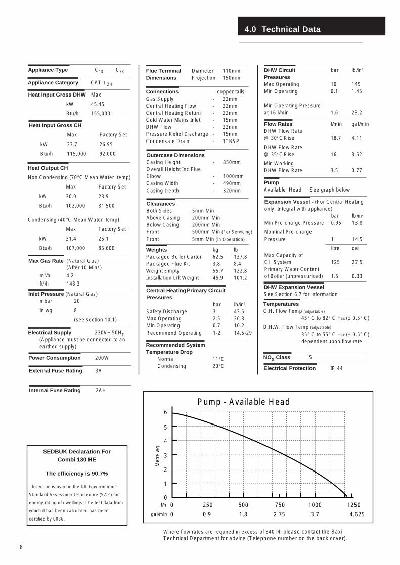
PumpAvailable Head See graph below
Expansion Vessel - (For Central Heatingonly. Integral with appliance)
bar lb/in2
Min Pre-charge Pressure 0.95 13.8
Nominal Pre-charge Pressure 1 14.5
litre galMax Capacity of CH System 125 27.5Primary Water Contentof Boiler (unpressurised) 1.5 0.33
Connections copper tailsGas Supply - 22mmCentral Heating Flow - 22mmCentral Heating Return - 22mmCold Water Mains Inlet - 15mmDHW Flow - 22mmPressure Relief Discharge - 15mmCondensate Drain - 1” BSP
Recommended SystemTemperature Drop
Normal 11°CCondensing 20°C
TemperaturesC.H. Flow Temp (adjustable)
45° C to 82° C max (± 0.5° C)
D.H.W. Flow Temp (adjustable)
35° C to 55° C max (± 0.5° C)dependent upon flow rate
Heat Input Gross DHW Max
kW 45.45
Btu/h 155,000
Heat Output CH
Non Condensing (70°C Mean Water temp)
Max Factory Set
kW 30.0 23.9
Btu/h 102,000 81,500
Condensing (40°C Mean Water temp)
Max Factory Set
kW 31.4 25.1
Btu/h 107,000 85,600
Electrical Supply 230V~ 50Hz (Appliance must be connected to an earthed supply)
Power Consumption 200W
External Fuse Rating 3A
Internal Fuse Rating 2AH
Appliance Category CAT I 2H
Max Gas Rate (Natural Gas)(After 10 Mins)
m3/h 4.2
ft3/h 148.3
Inlet Pressure (Natural Gas)mbar 20
in wg 8
(see section 10.1)
0250 500 750 1000
0 0.9 1.8 2.75 3.7
1
2
3
4
5
6
Met
re w
g
l/h
gal/min
Pump - Available Head
0 1250
4.625
Appliance Type C13 C33
NOx Class 5
DHW Expansion VesselSee Section 6.7 for information
Where flow rates are required in excess of 840 l/h please contact the BaxiTechnical Department for advice (Telephone number on the back cover).
The efficiency is 90.7%
This value is used in the UK Government’s
Standard Assessment Procedure (SAP) for
energy rating of dwellings. The test data from
which it has been calculated has been
certified by 0086.
SEDBUK Declaration For Combi 130 HE
Heat Input Gross CH
Max Factory Set
kW 33.7 26.95
Btu/h 115,000 92,000
Electrical Protection IP 44
5.0 Dimensions and Fixings
9
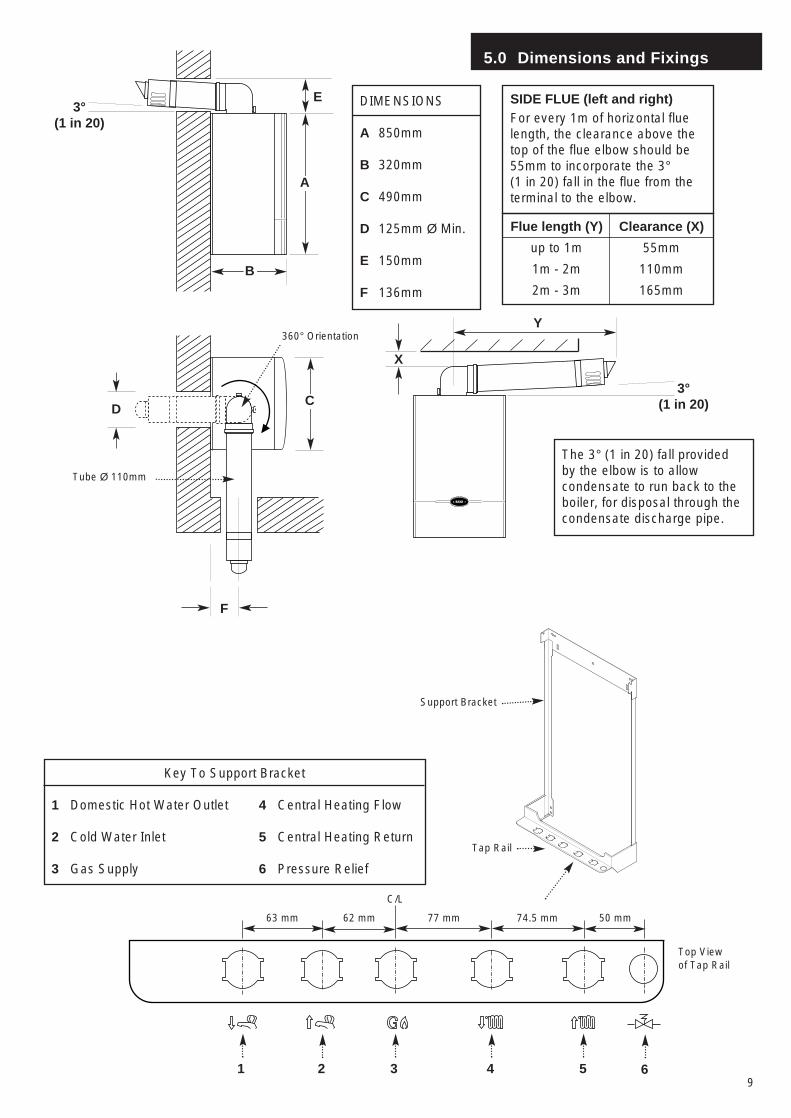
Key To Support Bracket
1 Domestic Hot Water Outlet 4 Central Heating Flow
2 Cold Water Inlet 5 Central Heating Return
3 Gas Supply 6 Pressure Relief
Support Bracket
1 2 3 4 5
63 mm 62 mm 77 mm 74.5 mm
Tap Rail
Top Viewof Tap Rail
C/L
6
50 mm
360° Orientation
Tube Ø 110mm
DC
B
A
E
F
3°(1 in 20)
DIMENSIONS
A 850mm
B 320mm
C 490mm
D 125mm Ø Min.
E 150mm
F 136mm
SIDE FLUE (left and right)For every 1m of horizontal fluelength, the clearance above thetop of the flue elbow should be55mm to incorporate the 3°(1 in 20) fall in the flue from theterminal to the elbow.
The 3° (1 in 20) fall providedby the elbow is to allowcondensate to run back to theboiler, for disposal through thecondensate discharge pipe.
Flue length (Y)
up to 1m
1m - 2m
2m - 3m
Clearance (X)
55mm
110mm
165mm
Y
3°(1 in 20)
X
6.0 System Details
10
6.1 Information
In GB it is necessary to comply with the WaterSupply (Water Fittings) Regulations 1999 (or forScotland, The Water Byelaws 2000, Scotland).The Baxi Combi 130 HE Combination Boiler is anApproved Product under the Water Regulations.
To comply with the Water Regulations your attentionis drawn to The Water Regulations Advisory Service(WRAS) which gives full details of the requirements.
In IE the requirements given in the current edition ofI.S. 813 “Domestic Gas Installations” and the currentBuilding Regulations must be followed.
6.2 Central Heating Circuit
1. The appliance is suitable for fully pumpedSEALED SYSTEMS ONLY.
This boiler is fitted with a flow switch interlock thatprevents it from firing when the heating demand issatisfied.
The boiler is designed so that it will heat the house tothe desired room temperature as quickly as possibleby running at the maximum boiler flow temperature of82°C.
When the room temperature is achieved the boilerwill then reduce the radiator temperature to as low alevel as possible, while still achieving the desiredroom temperature, thereby giving the most efficientuse of gas and the most comfortable roomtemperature possible.
The boiler will be able to achieve this performance ifa room thermostat is fitted or with a fully TRV’dsystem without a bypass. If the system is fully TRV’dwith a bypass then this feature will not be available,in this case the radiator temperature can be reducedto provide more efficient operation. (see Userinstructions).
• If the hot water delivery is greater than 18litres/minute the flow regulator must be fitted to theDomestic Hot Water inlet (A pint milk bottle will fill inunder 2 seconds).
• If the boiler is to be uprated to 100,000 Btu/hr CHoutput, an extra standard pump will be required andthe commissioning procedure will take approximately30 minutes longer.
• The condensate drain and pipes must be free fromleaks.
• Any timer and thermostat should be removedbefore installing optional Intellistat as it will overridetheir operation.
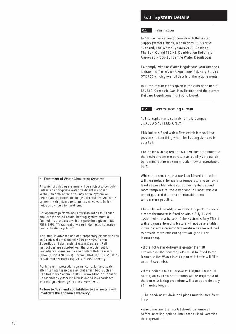
• Treatment of Water Circulating Systems
All water circulating systems will be subject to corrosionunless an appropriate water treatment is applied.Without treatment the efficiency of the system willdeteriorate as corrosion sludge accumulates within thesystem, risking damage to pump and valves, boilernoise and circulation problems.
For optimum performance after installation this boilerand its associated central heating system must beflushed in accordance with the guidelines given in BS7593:1992. “Treatment of water in domestic hot watercentral heating systems”.
This must involve the use of a proprietary cleanser, suchas BetzDearborn Sentinel X300 or X400, FernoxSuperfloc or Salamander System Cleanser. Fullinstructions are supplied with the products, but forimmediate information please contact BetzDearborn(0044 (0)151 420 9563), Fernox (0044 (0)1799 550 811)or Salamander (0044 (0)121 378 0952) directly.
For long term protection against corrosion and scale,after flushing it is necessary that an inhibitor such asBetzDearborn Sentinel X100, Fernox MB-1 or Copal orSalamander System Inhibitor is dosed in accordancewith the guidelines given in BS 7593:1992.
Failure to flush and add inhibitor to the system willinvalidate the appliance warranty.
6.0 System Details
11
6.3 System Control
1. The boiler is designed for use in a heatingsystem that incorporates external controls, i.e. aminimum of a timer device.
2. Suitable timer kits are available as optionalextras.
3. For optimum operating conditions and maximumeconomy the fitting of the Baxi Intellistat, isrecommended.
6.4 System Filling and Pressurising
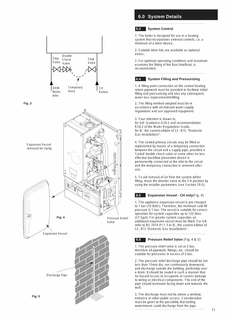
1. A filling point connection on the central heatingreturn pipework must be provided to facilitate initialfilling and pressurising and also any subsequentwater loss replacement/refilling.
2. The filling method adopted must be inaccordance with all relevant water supplyregulations and use approved equipment.
3. Your attention is drawn to,for GB: Guidance G24.2 and recommendationR24.2 of the Water Regulations Guide.for IE: the current edition of I.S. 813. "DomesticGas Installations".
4. The sealed primary circuits may be filled orreplenished by means of a temporary connectionbetween the circuit and a supply pipe, provided a'Listed' double check valve or some other no lesseffective backflow prevention device ispermanently connected at the inlet to the circuitand the temporary connection is removed afteruse.
5. To aid removal of air from the system whilstfilling, move the diverter valve to the CH position byusing the installer parameters (see Section 10.5).
6.5 Expansion Vessel - CH only(Fig. 4)
1. The appliance expansion vessel is pre-chargedto 1 bar (10 lb/in2). Therefore, the minimum cold fillpressure is 1 bar. The vessel is suitable for correctoperation for system capacities up to 125 litres(27.5gal). For greater system capacities anadditional expansion vessel must be fitted. For GBrefer to BS 7074 Pt 1. For IE, the current edition ofI.S. 813 “Domestic Gas Installations”.
6.6 Pressure Relief Valve (Fig. 4 & 5)
1. The pressure relief valve is set at 3 bar,therefore all pipework, fittings, etc. should besuitable for pressures in excess of 3 bar.
2. The pressure relief discharge pipe should be notless than 15mm dia, run continuously downward,and discharge outside the building, preferably overa drain. It should be routed in such a manner thatno hazard occurs to occupants or causes damageto wiring or electrical components. The end of thepipe should terminate facing down and towards thewall.
3. The discharge must not be above a window,entrance or other public access. Considerationmust be given to the possibility that boilingwater/steam could discharge from the pipe.
Fig. 3
Fig. 5
StopValve
DoubleCheckValve
DHWMainsInlet
CHReturn
TemporaryHose
Discharge Pipe
Pressure ReliefValve
Expansion Vesselremoved for clarity
Fig. 4
Expansion Vessel
StopValve
6.0 System Details
12
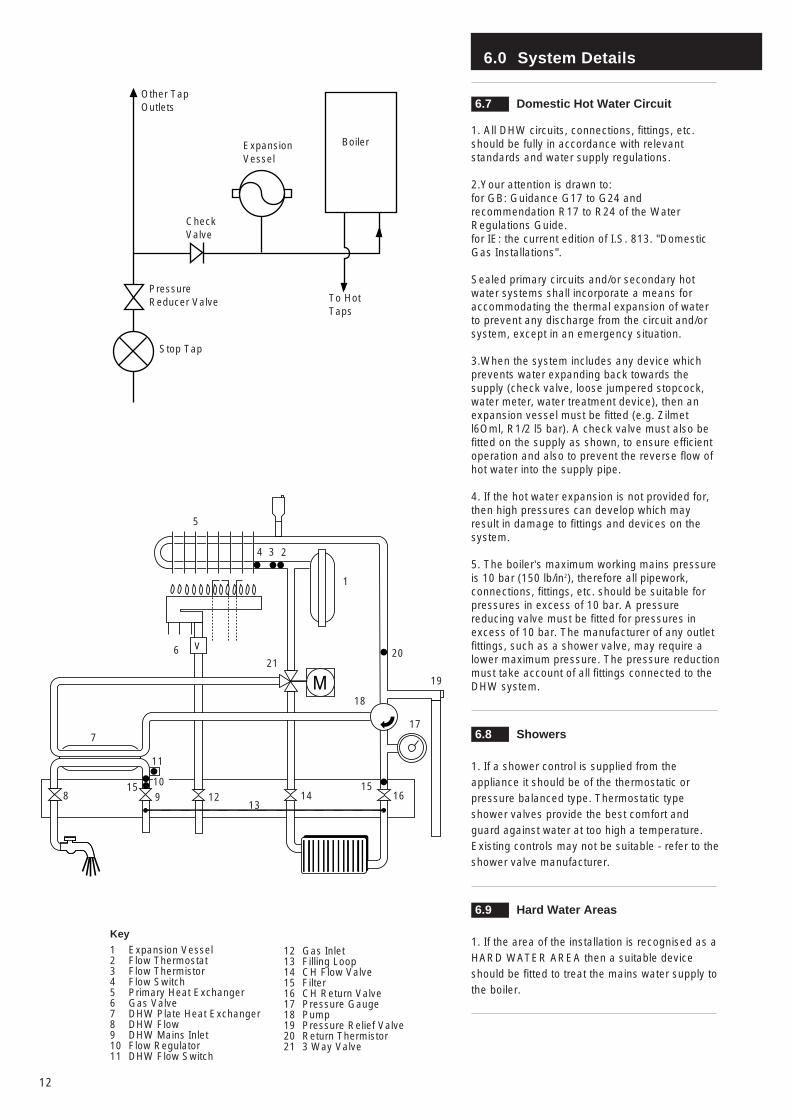
6.7 Domestic Hot Water Circuit
1. All DHW circuits, connections, fittings, etc.should be fully in accordance with relevantstandards and water supply regulations.
2.Your attention is drawn to:for GB: Guidance G17 to G24 andrecommendation R17 to R24 of the WaterRegulations Guide.for IE: the current edition of I.S. 813. "DomesticGas Installations".
Sealed primary circuits and/or secondary hotwater systems shall incorporate a means foraccommodating the thermal expansion of waterto prevent any discharge from the circuit and/orsystem, except in an emergency situation.
3.When the system includes any device whichprevents water expanding back towards thesupply (check valve, loose jumpered stopcock,water meter, water treatment device), then anexpansion vessel must be fitted (e.g. Zilmetl6Oml, R1/2 l5 bar). A check valve must also befitted on the supply as shown, to ensure efficientoperation and also to prevent the reverse flow ofhot water into the supply pipe.
4. If the hot water expansion is not provided for,then high pressures can develop which mayresult in damage to fittings and devices on thesystem.
5. The boiler’s maximum working mains pressureis 10 bar (150 lb/in2), therefore all pipework,connections, fittings, etc. should be suitable forpressures in excess of 10 bar. A pressurereducing valve must be fitted for pressures inexcess of 10 bar. The manufacturer of any outletfittings, such as a shower valve, may require alower maximum pressure. The pressure reductionmust take account of all fittings connected to theDHW system.
6.8 Showers
1. If a shower control is supplied from theappliance it should be of the thermostatic orpressure balanced type. Thermostatic typeshower valves provide the best comfort andguard against water at too high a temperature.Existing controls may not be suitable - refer to theshower valve manufacturer.
6.9 Hard Water Areas
1. If the area of the installation is recognised as aHARD WATER AREA then a suitable deviceshould be fitted to treat the mains water supply tothe boiler.
Key
1 Expansion Vessel2 Flow Thermostat3 Flow Thermistor4 Flow Switch5 Primary Heat Exchanger6 Gas Valve7 DHW Plate Heat Exchanger8 DHW Flow9 DHW Mains Inlet10 Flow Regulator11 DHW Flow Switch
Boiler
Other TapOutlets
ExpansionVessel
To HotTaps
CheckValve
PressureReducer Valve
Stop Tap
V
M
12 Gas Inlet13 Filling Loop14 CH Flow Valve15 Filter16 CH Return Valve17 Pressure Gauge18 Pump19 Pressure Relief Valve20 Return Thermistor21 3 Way Valve
1
5
4 3 2
2021
7
18
17
14129
11
16
19
13
10 15
6
815
7.0 Site Requirements
13
Zone 2
Zone 1
Zone 0
Zone 2Zone 3
Zone 3
Zone 2
WindowRecess
WindowRecess
0.6 m 2.4 m
Ceiling
OutsideZones
Outside Zones
Zone 3
Zone 3
Zone 2
Zone 2Zone 1
Zone 0
2.25 m
Zone 2
WindowRecess
3.0 m
2.4 m0.6 m
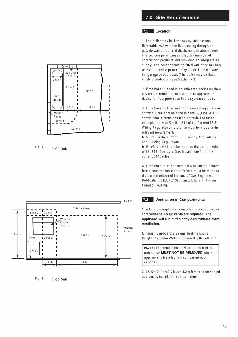
Fig. A
Fig. B
In GB Only
In GB Only
7.1 Location
1. The boiler may be fitted to any suitable non-flammable wall with the flue passing through anoutside wall or roof and discharging to atmospherein a position permitting satisfactory removal ofcombustion products and providing an adequate airsupply. The boiler should be fitted within the buildingunless otherwise protected by a suitable enclosurei.e. garage or outhouse. (The boiler may be fittedinside a cupboard - see Section 7.2).
2. If the boiler is sited in an unheated enclosure thenit is recommended to incorporate an appropriatedevice for frost protection in the system controls.
3. If the boiler is fitted in a room containing a bath orshower, it can only be fitted in zone 3, (Figs. A & Bshows zone dimensions for a bathtub. For otherexamples refer to Section 601 of the Current I.E.E.Wiring Regulations) reference must be made to therelevant requirements.In GB this is the current I.E.E. Wiring Regulationsand Building Regulations.In IE reference should be made to the current editionof I.S. 813 “Domestic Gas Installations” and thecurrent ETCI rules.
4. If the boiler is to be fitted into a building of timberframe construction then reference must be made tothe current edition of Institute of Gas EngineersPublication IGE/UP/7 (Gas Installations in TimberFramed Housing.
7.2 Ventilation of Compartments
1. Where the appliance is installed in a cupboard orcompartment, no air vents are required. Theappliance will run sufficiently cool without extraventilation.
Minimum Cupboard Size (inside dimensions)Height - 1250mm Width - 590mm Depth - 400mm
NOTE: The ventilation label on the front of theouter case MUST NOT BE REMOVED when theappliance is installed in a compartment orcupboard.
2. BS 5440: Part 2 Clause 4.2 refers to room sealedappliances installed in compartments.
7.0 Site Requirements
14
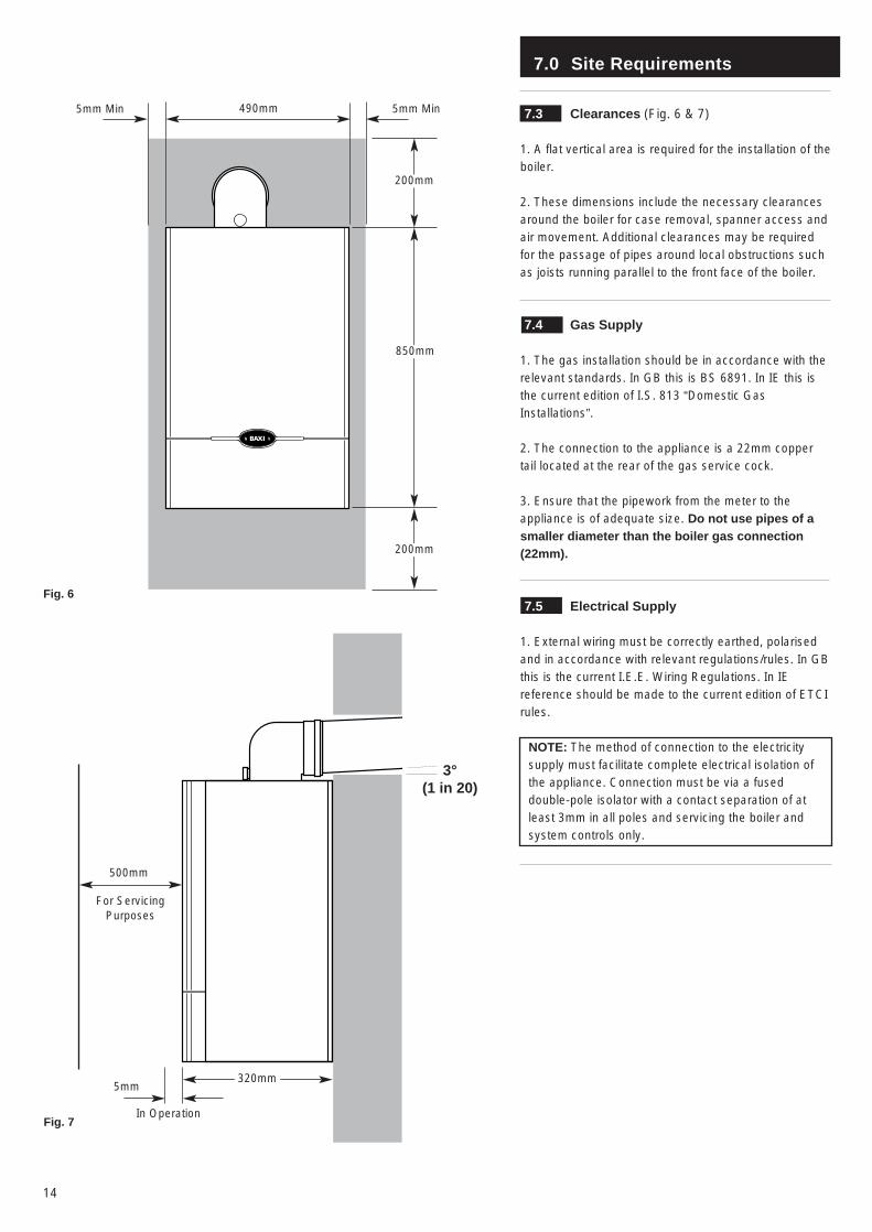
7.3 Clearances (Fig. 6 & 7)
1. A flat vertical area is required for the installation of theboiler.
2. These dimensions include the necessary clearancesaround the boiler for case removal, spanner access andair movement. Additional clearances may be requiredfor the passage of pipes around local obstructions suchas joists running parallel to the front face of the boiler.
7.4 Gas Supply
1. The gas installation should be in accordance with therelevant standards. In GB this is BS 6891. In IE this isthe current edition of I.S. 813 “Domestic GasInstallations”.
2. The connection to the appliance is a 22mm coppertail located at the rear of the gas service cock.
3. Ensure that the pipework from the meter to theappliance is of adequate size. Do not use pipes of asmaller diameter than the boiler gas connection(22mm).
7.5 Electrical Supply
1. External wiring must be correctly earthed, polarisedand in accordance with relevant regulations/rules. In GBthis is the current I.E.E. Wiring Regulations. In IEreference should be made to the current edition of ETCIrules.
NOTE: The method of connection to the electricitysupply must facilitate complete electrical isolation ofthe appliance. Connection must be via a fuseddouble-pole isolator with a contact separation of atleast 3mm in all poles and servicing the boiler andsystem controls only.
200mm
850mm
490mm
200mm
5mm Min5mm Min
5mm
500mm
For ServicingPurposes
Fig. 6
Fig. 7In Operation
3°(1 in 20)
320mm
7.0 Site Requirements
15
Boiler
2.5° Minimum fall
Termination to an internal soiland vent pipe
450mm min
Boiler
2.5° Minimum fall
External termination via internaldischarge branch
e.g sink waste - downstream
SinkPipe must terminateabove water level butbelow surroundingsurface
BoilerPipe must terminateabove water level butbelow surroundingsurface
2.5° Minimum fall
Termination to a drain or gully
Boiler
500mm min
2.5° Minimum fall
Termination to a purpose madesoak-away
Holes in the soak-awaymust face away from thebuilding
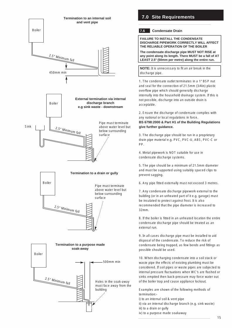
7.6 Condensate Drain
FAILURE TO INSTALL THE CONDENSATEDISCHARGE PIPEWORK CORRECTLY WILL AFFECTTHE RELIABLE OPERATION OF THE BOILER
The condensate discharge pipe MUST NOT RISE atany point along its length. There MUST be a fall of ATLEAST 2.5° (50mm per metre) along the entire run.
NOTE: It is unnecessary to fit an air break in thedischarge pipe.
1. The condensate outlet terminates in a 1” BSP nutand seal for the connection of 21.5mm (3/4in) plasticoverflow pipe which should generally dischargeinternally into the household drainage system. If this isnot possible, discharge into an outside drain isacceptable.
2. Ensure the discharge of condensate complies withany national or local regulations in force. BS 6798:2000 & Part H1 of the Building Regulationsgive further guidance.
3. The discharge pipe should be run in a proprietarydrain pipe material e.g. PVC, PVC-U, ABS, PVC-C orPP.
4. Metal pipework is NOT suitable for use incondensate discharge systems.
5. The pipe should be a minimum of 21.5mm diameterand must be supported using suitably spaced clips toprevent sagging.
6. Any pipe fitted externally must not exceed 3 metres.
7. Any condensate discharge pipework external to thebuilding (or in an unheated part of it e.g. garage) mustbe insulated to protect against frost. It is alsorecommended that the pipe diameter is increased to32mm.
8. If the boiler is fitted in an unheated location the entirecondensate discharge pipe should be treated as anexternal run.
9. In all cases discharge pipe must be installed to aiddisposal of the condensate. To reduce the risk ofcondensate being trapped, as few bends and fittings aspossible should be used.
10. When discharging condensate into a soil stack orwaste pipe the effects of existing plumbing must beconsidered. If soil pipes or waste pipes are subjected tointernal pressure fluctuations when WC's are flushed orsinks emptied then back-pressure may force water outof the boiler trap and cause appliance lockout.
Examples are shown of the following methods oftermination:-i) to an internal soil & vent pipeii) via an internal discharge branch (e.g. sink waste)iii) to a drain or gullyiv) to a purpose made soakaway
7.0 Site Requirements
16
N
I
I
G
F
M
I
AA
F
H
J,K
DE
H
Likely flue positions requiring a flue terminal guard
C
RA
I
J,K
I
L
S
B
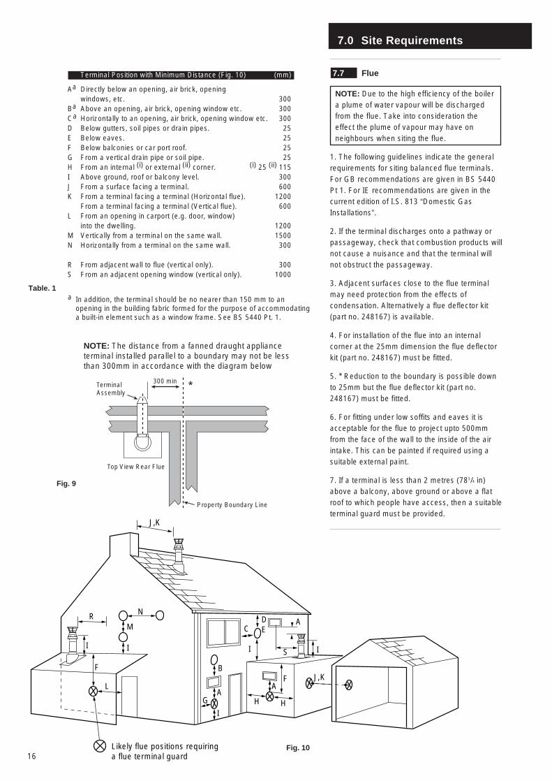
7.7 Flue
NOTE: Due to the high efficiency of the boilera plume of water vapour will be dischargedfrom the flue. Take into consideration theeffect the plume of vapour may have onneighbours when siting the flue.
1. The following guidelines indicate the generalrequirements for siting balanced flue terminals.For GB recommendations are given in BS 5440Pt 1. For IE recommendations are given in thecurrent edition of I.S. 813 “Domestic GasInstallations”.
2. If the terminal discharges onto a pathway orpassageway, check that combustion products willnot cause a nuisance and that the terminal willnot obstruct the passageway.
3. Adjacent surfaces close to the flue terminalmay need protection from the effects ofcondensation. Alternatively a flue deflector kit(part no. 248167) is available.
4. For installation of the flue into an internalcorner at the 25mm dimension the flue deflectorkit (part no. 248167) must be fitted.
5. * Reduction to the boundary is possible downto 25mm but the flue deflector kit (part no.248167) must be fitted.
6. For fitting under low soffits and eaves it isacceptable for the flue to project upto 500mmfrom the face of the wall to the inside of the airintake. This can be painted if required using asuitable external paint.
7. If a terminal is less than 2 metres (783/4 in)above a balcony, above ground or above a flatroof to which people have access, then a suitableterminal guard must be provided.
Fig. 10
Fig. 9
300 minTerminalAssembly
Top View Rear Flue
Property Boundary Line
NOTE: The distance from a fanned draught applianceterminal installed parallel to a boundary may not be lessthan 300mm in accordance with the diagram below
Table. 1
Terminal Position with Minimum Distance (Fig. 10) (mm)
Aa Directly below an opening, air brick, opening windows, etc. 300
Ba Above an opening, air brick, opening window etc. 300Ca Horizontally to an opening, air brick, opening window etc. 300D Below gutters, soil pipes or drain pipes. 25E Below eaves. 25F Below balconies or car port roof. 25G From a vertical drain pipe or soil pipe. 25H From an internal (i) or external (ii) corner. (i) 25 (ii) 115I Above ground, roof or balcony level. 300J From a surface facing a terminal. 600K From a terminal facing a terminal (Horizontal flue). 1200
From a terminal facing a terminal (Vertical flue). 600L From an opening in carport (e.g. door, window)
into the dwelling. 1200M Vertically from a terminal on the same wall. 1500N Horizontally from a terminal on the same wall. 300
R From adjacent wall to flue (vertical only). 300S From an adjacent opening window (vertical only). 1000
a In addition, the terminal should be no nearer than 150 mm to an opening in the building fabric formed for the purpose of accommodating a built-in element such as a window frame. See BS 5440 Pt. 1.
*
7.0 Site Requirements
17
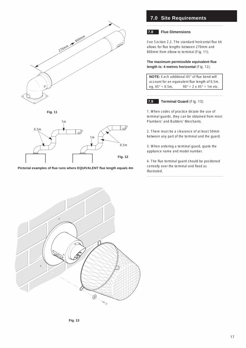
7.8 Flue Dimensions
See Section 2.2. The standard horizontal flue kitallows for flue lengths between 270mm and800mm from elbow to terminal (Fig. 11).
The maximum permissible equivalent fluelength is: 4 metres horizontal (Fig. 12).
NOTE: Each additional 45° of flue bend willaccount for an equivalent flue length of 0.5m.eg. 45° = 0.5m, 90° = 2 x 45° = 1m etc.
7.9 Terminal Guard (Fig. 13)
1. When codes of practice dictate the use ofterminal guards, they can be obtained from mostPlumbers’ and Builders’ Merchants.
2. There must be a clearance of at least 50mmbetween any part of the terminal and the guard.
3. When ordering a terminal guard, quote theappliance name and model number.
4. The flue terminal guard should be positionedcentrally over the terminal and fixed asillustrated.
Fig. 11
Fig. 12
Pictorial examples of flue runs where EQUIVALENT flue length equals 4m
Fig. 13
270mm
800mm
0.5m
1m
1m
0.5m
7.0 Site Requirement
18
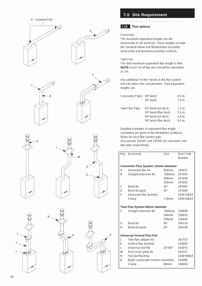
Key Accessory Size Baxi CodeNumber
Concentric Flue System 110mm diameterA Horizontal flue kit 850mm 236921B Straight extension kit 1000mm 241695
500mm 241694250mm 241692
C Bend kit 93° 241687D Bend kit (pair) 45° 241689E Horizontal flue terminal 243013BAX
Clamp 110mm 243014BAX
Twin Flue System 80mm diameterF Straight extension kit 1000mm 238690
500mm 238692250mm 238694
G Bend kit 90° 246139H Bend kit (pair) 45° 246138
Universal Vertical Flue KitsJ Twin flue adaptor kit 242757K Vertical flue terminal 242802L Universal roof tile 25°/50° 243015M Roof cover plate kit 243131N Flat roof flashing 243016BAXR Boiler connection vertical concentric 242886
Clamp 80mm 238684
7.10 Flue options
ConcentricThe maximum equivalent lengths are 4m(horizontal) or 5m (vertical). These lengths excludethe standard elbow and flue/terminal assembly(horizontal) and terminal assembly (vertical).
Twin FlueThe total maximum equivalent flue length is 40m.NOTE: Each 1m of flue duct should be calculatedas 2m.
Any additional “in line” bends in the flue systemmust be taken into consideration. Their equivalentlengths are:
Concentric Pipes: 45º bend 0.5 m93º bend 1.0 m
Twin Flue Pipe: 45º bend (air duct) 1.3 m45º bend (flue duct) 2.6 m90º bend (air duct) 4.8 m90º bend (flue duct) 9.6 m
Detailed examples of equivalent flue lengthcalculation are given in the Installation GuidanceNotes for each flue system type.(Documents 243501 and 243502 for concentric andtwin pipe respectively).
A - Standard Flue
D
C
B
E
K
L
M
D
J
F
J
N
H G
R
8.0 Installation
19
Check Site Requirements (section 7.0) beforecommencing.
Fitting an Extra Pump
To extract 100,000 Btu/hr from the boiler incentral heating mode an extra pump will need tobe fitted to increase flow. It must be fitted inparallel to the existing pump and in the returnpipe. See Pages 24 & 25 for wiring details.
8.1 Initial Preparation
The gas supply, gas type and pressure must bechecked for suitability before connection (seeSection 7.4).
NOTE: If the boiler is to be pre-plumbed, followboth these instructions and those on the boilerpack.
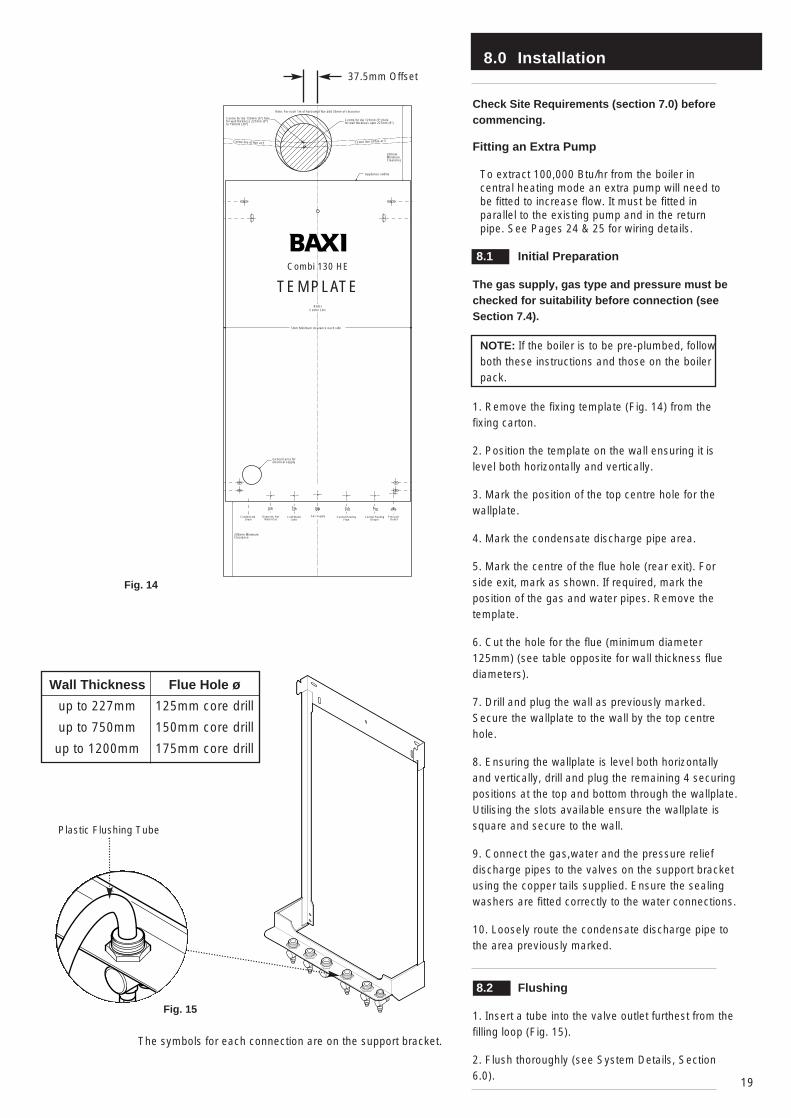
1. Remove the fixing template (Fig. 14) from thefixing carton.
2. Position the template on the wall ensuring it islevel both horizontally and vertically.
3. Mark the position of the top centre hole for thewallplate.
4. Mark the condensate discharge pipe area.
5. Mark the centre of the flue hole (rear exit). Forside exit, mark as shown. If required, mark theposition of the gas and water pipes. Remove thetemplate.
6. Cut the hole for the flue (minimum diameter125mm) (see table opposite for wall thickness fluediameters).
7. Drill and plug the wall as previously marked.Secure the wallplate to the wall by the top centrehole.
8. Ensuring the wallplate is level both horizontallyand vertically, drill and plug the remaining 4 securingpositions at the top and bottom through the wallplate.Utilising the slots available ensure the wallplate issquare and secure to the wall.
9. Connect the gas,water and the pressure reliefdischarge pipes to the valves on the support bracketusing the copper tails supplied. Ensure the sealingwashers are fitted correctly to the water connections.
10. Loosely route the condensate discharge pipe tothe area previously marked.
8.2 Flushing
1. Insert a tube into the valve outlet furthest from thefilling loop (Fig. 15).
2. Flush thoroughly (see System Details, Section6.0).
Wall Thickness
up to 227mm
up to 750mm
up to 1200mm
Flue Hole ø
125mm core drill
150mm core drill
175mm core drill
Plastic Flushing Tube
Fig. 15
Fig. 14
Centre for dia 125mm (5") holefor wall thickness upto 227mm (9")
Centre for dia 150mm (6") holefor wall thickness 227mm (9")to 750mm (30")
Note: For each 1m of horizontal flue add 55mm of clearance
Centre line of flue at 3 Centre line of flue at 3
General area for electrical supply
5mm Minimum clearance each side
Appliance outline
Gas Supply Central HeatingReturn
Central HeatingFlow
Cold WaterInlet
Domestic HotWater Out
Condensate Drain
Pressure Relief
Combi 130 HE
TEMPLATEBoiler
Centre Line
200mm MinimumClearance
200mm MinimumClearance
37.5mm Offset
The symbols for each connection are on the support bracket.
8.0 Installation
20
Fig. 16
Fig. 17
Outer CaseFixing Screw
Lower DoorPanel
Service Guidance NoteLabel on inside of panel
8.3 Preparing The Boiler
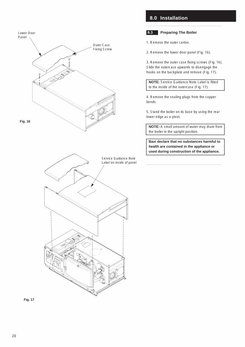
1. Remove the outer carton.
2. Remove the lower door panel (Fig. 16).
3. Remove the outer case fixing screws (Fig. 16).Slide the outercase upwards to disengage thehooks on the backplate and remove (Fig. 17).
NOTE: Service Guidance Note Label is fittedto the inside of the outercase (Fig. 17).
4. Remove the sealing plugs from the copperbends.
5. Stand the boiler on its base by using the rearlower edge as a pivot.
NOTE: A small amount of water may drain fromthe boiler in the upright position.
Baxi declare that no substances harmful tohealth are contained in the appliance orused during construction of the appliance.
8.0 Installation
21
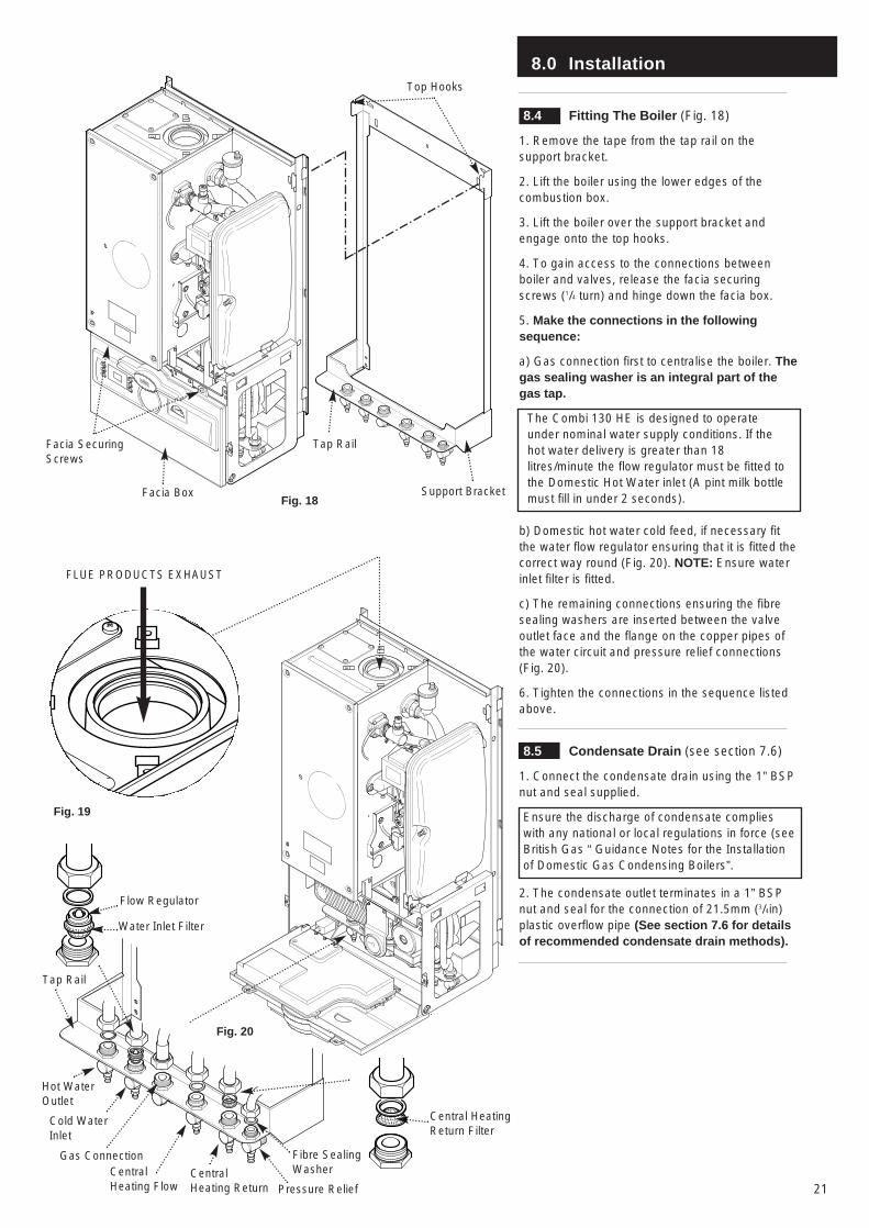
8.4 Fitting The Boiler (Fig. 18)
1. Remove the tape from the tap rail on thesupport bracket.
2. Lift the boiler using the lower edges of thecombustion box.
3. Lift the boiler over the support bracket andengage onto the top hooks.
4. To gain access to the connections betweenboiler and valves, release the facia securingscrews (1/4 turn) and hinge down the facia box.
5. Make the connections in the followingsequence:
a) Gas connection first to centralise the boiler. Thegas sealing washer is an integral part of thegas tap.
The Combi 130 HE is designed to operateunder nominal water supply conditions. If thehot water delivery is greater than 18litres/minute the flow regulator must be fitted tothe Domestic Hot Water inlet (A pint milk bottlemust fill in under 2 seconds).
b) Domestic hot water cold feed, if necessary fitthe water flow regulator ensuring that it is fitted thecorrect way round (Fig. 20). NOTE: Ensure waterinlet filter is fitted.
c) The remaining connections ensuring the fibresealing washers are inserted between the valveoutlet face and the flange on the copper pipes ofthe water circuit and pressure relief connections(Fig. 20).
6. Tighten the connections in the sequence listedabove.
8.5 Condensate Drain (see section 7.6)
1. Connect the condensate drain using the 1” BSPnut and seal supplied.
Ensure the discharge of condensate complieswith any national or local regulations in force (seeBritish Gas “ Guidance Notes for the Installationof Domestic Gas Condensing Boilers”.
2. The condensate outlet terminates in a 1” BSPnut and seal for the connection of 21.5mm (3/4in)plastic overflow pipe (See section 7.6 for detailsof recommended condensate drain methods).
Top Hooks
Support BracketFacia Box
Facia SecuringScrews
Gas Connection
Tap Rail
Fig. 18
Fig. 20
FLUE PRODUCTS EXHAUST
Tap Rail
Central HeatingReturn Filter
Fig. 19
Fibre SealingWasher
Flow Regulator
Water Inlet Filter
Hot WaterOutlet
Cold WaterInlet
CentralHeating Flow
CentralHeating Return Pressure Relief
8.0 Installation
22
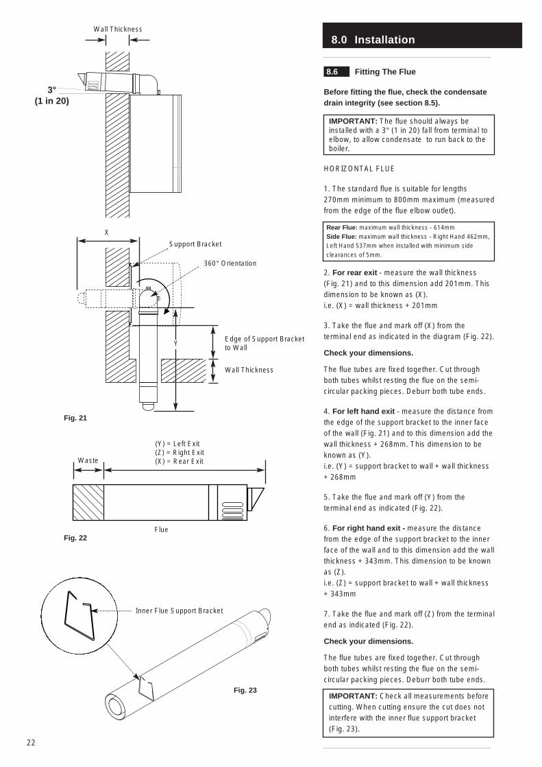
8.6 Fitting The Flue
Before fitting the flue, check the condensatedrain integrity (see section 8.5).
IMPORTANT: The flue should always beinstalled with a 3° (1 in 20) fall from terminal toelbow, to allow condensate to run back to theboiler.
HORIZONTAL FLUE
1. The standard flue is suitable for lengths270mm minimum to 800mm maximum (measuredfrom the edge of the flue elbow outlet).
Rear Flue: maximum wall thickness - 614mmSide Flue: maximum wall thickness - Right Hand 462mm, Left Hand 537mm when installed with minimum sideclearances of 5mm.
2. For rear exit - measure the wall thickness (Fig. 21) and to this dimension add 201mm. Thisdimension to be known as (X).i.e. (X) = wall thickness + 201mm
3. Take the flue and mark off (X) from theterminal end as indicated in the diagram (Fig. 22).
Check your dimensions.
The flue tubes are fixed together. Cut throughboth tubes whilst resting the flue on the semi-circular packing pieces. Deburr both tube ends.
4. For left hand exit - measure the distance fromthe edge of the support bracket to the inner faceof the wall (Fig. 21) and to this dimension add thewall thickness + 268mm. This dimension to beknown as (Y).i.e. (Y) = support bracket to wall + wall thickness+ 268mm
5. Take the flue and mark off (Y) from theterminal end as indicated (Fig. 22).
6. For right hand exit - measure the distancefrom the edge of the support bracket to the innerface of the wall and to this dimension add the wallthickness + 343mm. This dimension to be knownas (Z).i.e. (Z) = support bracket to wall + wall thickness+ 343mm
7. Take the flue and mark off (Z) from the terminalend as indicated (Fig. 22).
Check your dimensions.
The flue tubes are fixed together. Cut throughboth tubes whilst resting the flue on the semi-circular packing pieces. Deburr both tube ends.
IMPORTANT: Check all measurements beforecutting. When cutting ensure the cut does notinterfere with the inner flue support bracket (Fig. 23).
360° Orientation
Inner Flue Support Bracket
Wall Thickness
YEdge of Support Bracketto Wall
Wall Thickness
(Y) = Left Exit(Z) = Right Exit(X) = Rear Exit
Flue
Waste
Fig. 21
Fig. 22
Fig. 23
3°(1 in 20)
X
Support Bracket

8.0 Installation
23
8.6 Fitting the Flue (Cont)
8. Ensure the inner flue support bracket ispositioned in the flue (Fig. 24).
9. Engage the flue into the flue elbow usingsoap solution to ease the engagement ensuringthe flue is assembled as shown (Fig. 25).
10. Place the gasket over the flue exit on theboiler (Fig. 25).
11. Slide the flue assembly through the hole inthe wall. Ensure angled inner end slopesdownwards (Fig. 26).
12. Engage the elbow on to the flue connectionon top of the boiler. Secure with the four screwssupplied in the kit.
13. Make good between the wall and air ductoutside the building ensuring the 3° dropbetween the terminal and elbow.
14. The flue trim should be fitted once theinstallation is complete and the flue secure (Fig. 26). Making sure the brickwork is dust freeand dry apply a suitable mastic to the inside ofthe trim and press against the wall finish,
15. If necessary fit a terminal guard (seeSection 7.9).
VERTICAL FLUEING
Only flues approved with the Baxi Combi 130HE Boiler can be used.
For information on vertical flues consult theBaxi Combination Boilers Brochure or Notesfor Guidance supplied with the vertical fluepack.
Gasket
Flue Trim
Inner Flue Support Bracket
Flue
Flue Elbow
Fig. 24
Fig. 26
Fig. 25
8.0 Installation
24
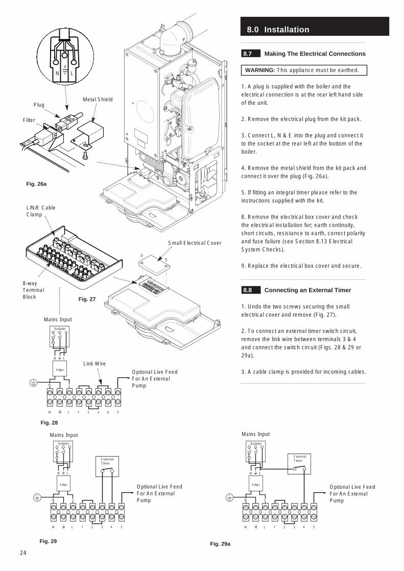
8.7 Making The Electrical Connections
WARNING: This appliance must be earthed.
1. A plug is supplied with the boiler and theelectrical connection is at the rear left hand sideof the unit.
2. Remove the electrical plug from the kit pack.
3. Connect L, N & E into the plug and connect itto the socket at the rear left at the bottom of theboiler.
4. Remove the metal shield from the kit pack andconnect it over the plug (Fig. 26a).
5. If fitting an integral timer please refer to theinstructions supplied with the kit.
8. Remove the electrical box cover and checkthe electrical installation for; earth continuity,short circuits, resistance to earth, correct polarityand fuse failure (see Section 8.13 ElectricalSystem Checks).
9. Replace the electrical box cover and secure.
8.8 Connecting an External Timer
1. Undo the two screws securing the smallelectrical cover and remove (Fig. 27).
2. To connect an external timer switch circuit,remove the link wire between terminals 3 & 4and connect the switch circuit (Figs. 28 & 29 or29a).
3. A cable clamp is provided for incoming cables.Filter
N L
Isolator
N L
1LN 2 3 4 5
Filter
N L
Isolator
N L
1LN 2 3 4 5
ExternalTimer
Small Electrical Cover
Fig. 27
Fig. 28
Fig. 29
Optional Live FeedFor An ExternalPump
Optional Live FeedFor An ExternalPump
L/N/E CableClamp
8-wayTerminalBlock
Mains Input
Mains Input
Fig. 26a
Filter
PlugMetal Shield
N L
Filter
N L
Isolator
N L
1LN 2 3 4 5
ExternalTimer
Mains Input
Optional Live FeedFor An ExternalPump
Fig. 29a
Link Wire
8.0 Installation
25
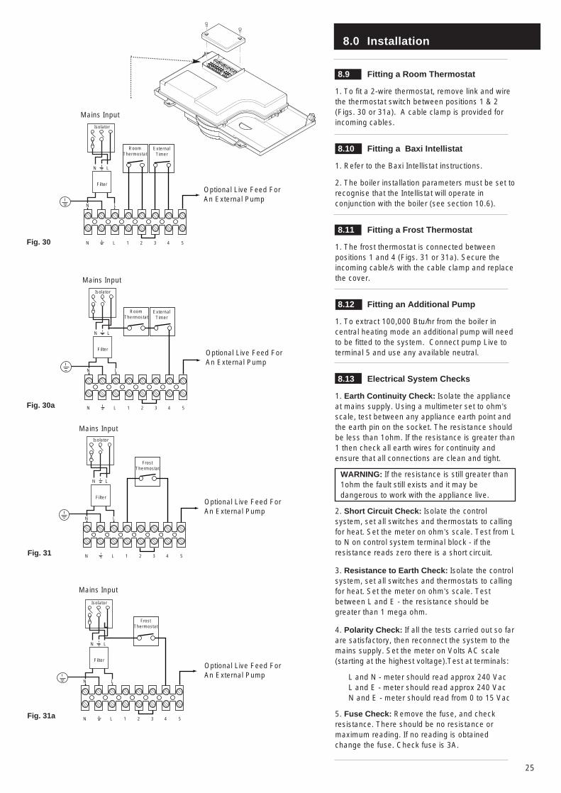
8.9 Fitting a Room Thermostat
1. To fit a 2-wire thermostat, remove link and wirethe thermostat switch between positions 1 & 2(Figs. 30 or 31a). A cable clamp is provided forincoming cables.
8.10 Fitting a Baxi Intellistat
1. Refer to the Baxi Intellistat instructions.
2. The boiler installation parameters must be set torecognise that the Intellistat will operate inconjunction with the boiler (see section 10.6).
8.11 Fitting a Frost Thermostat
1. The frost thermostat is connected betweenpositions 1 and 4 (Figs. 31 or 31a). Secure theincoming cable/s with the cable clamp and replacethe cover.
8.12 Fitting an Additional Pump
1. To extract 100,000 Btu/hr from the boiler incentral heating mode an additional pump will needto be fitted to the system. Connect pump Live toterminal 5 and use any available neutral.
8.13 Electrical System Checks
1. Earth Continuity Check: Isolate the applianceat mains supply. Using a multimeter set to ohm’sscale, test between any appliance earth point andthe earth pin on the socket. The resistance shouldbe less than 1ohm. If the resistance is greater than1 then check all earth wires for continuity andensure that all connections are clean and tight.
WARNING: If the resistance is still greater than1ohm the fault still exists and it may bedangerous to work with the appliance live.
2. Short Circuit Check: Isolate the controlsystem, set all switches and thermostats to callingfor heat. Set the meter on ohm’s scale. Test from Lto N on control system terminal block - if theresistance reads zero there is a short circuit.
3. Resistance to Earth Check: Isolate the controlsystem, set all switches and thermostats to callingfor heat. Set the meter on ohm’s scale. Testbetween L and E - the resistance should begreater than 1 mega ohm.
4. Polarity Check: If all the tests carried out so farare satisfactory, then reconnect the system to themains supply. Set the meter on Volts AC scale(starting at the highest voltage).Test at terminals:
L and N - meter should read approx 240 VacL and E - meter should read approx 240 VacN and E - meter should read from 0 to 15 Vac
5. Fuse Check: Remove the fuse, and checkresistance. There should be no resistance ormaximum reading. If no reading is obtainedchange the fuse. Check fuse is 3A.
Filter
N L
Isolator
N L
1LN 2 3 4 5
ExternalTimer
RoomThermostat
Optional Live Feed ForAn External Pump
Fig. 30
Filter
N L
Isolator
N L
1LN 2 3 4 5
FrostThermostat
Fig. 31
Optional Live Feed ForAn External Pump
Mains Input
Mains Input
Filter
N L
Isolator
N L
1LN 2 3 4 5
ExternalTimer
RoomThermostat
Optional Live Feed ForAn External Pump
Fig. 30a
Mains Input
Filter
N L
Isolator
N L
1LN 2 3 4 5
FrostThermostat
Fig. 31a
Optional Live Feed ForAn External Pump
Mains Input
L
9.0 Electrical
26
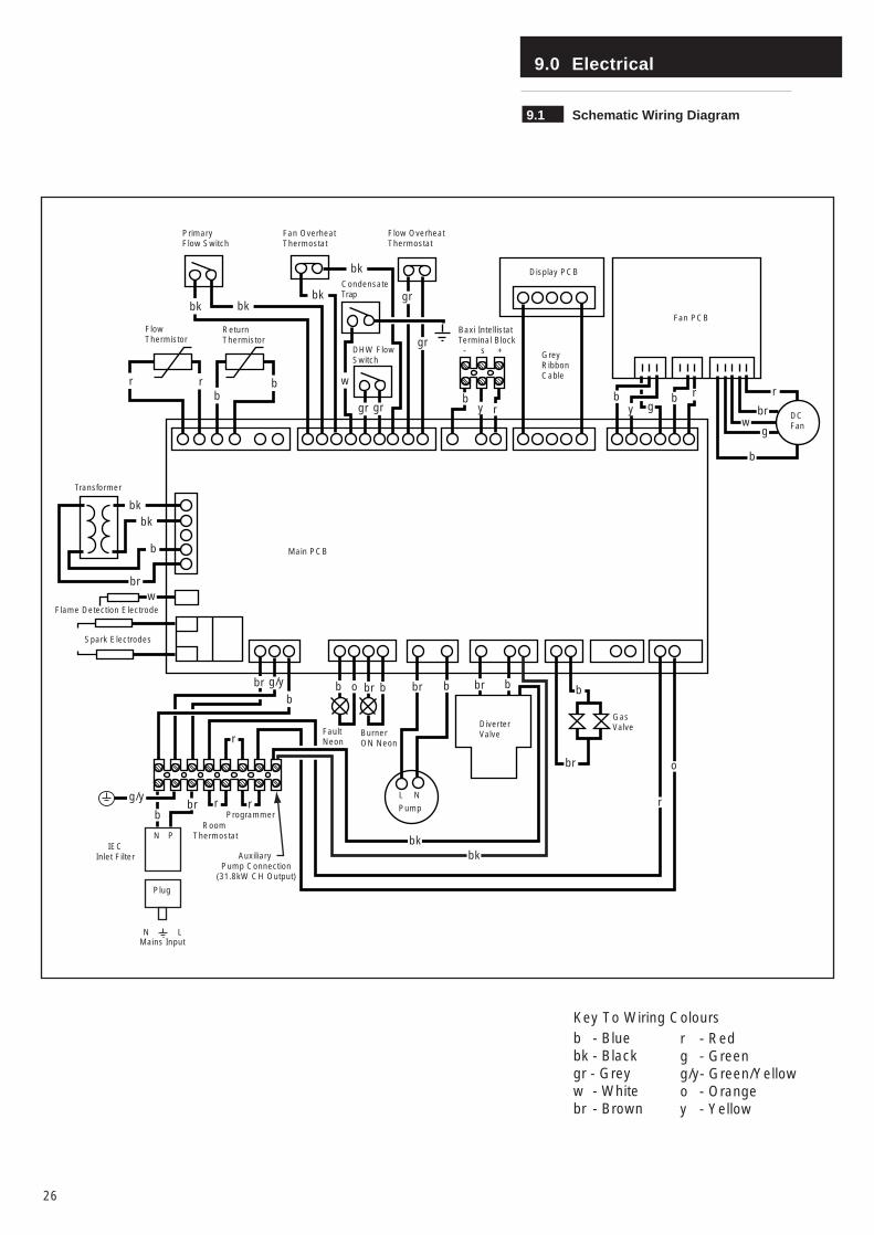
9.1 Schematic Wiring Diagram
PrimaryFlow Switch
Fan OverheatThermostat
Flow OverheatThermostat
CondensateTrap
DHW FlowSwitch
Flow Thermistor
bk
Return Thermistor
bk
r r bb
bk
bk
w
gr gr
gr
gr
by r
Baxi IntellistatTerminal Block - s + Grey
RibbonCable
Display PCB
Fan PCB
bg
r r
g
b
wbr DC
Fan
Main PCB
Transformer
Flame Detection Electrode
Spark Electrodes
bkbk
b
brw
br
r
r rProgrammer
Room Thermostat
Mains InputN L
FaultNeon
Burner ON Neon
bbrb o bbr
NL
Pump
DiverterValve
br b
br
b
GasValve
r
o
Auxiliary Pump Connection
(31.8kW CH Output)
brb
N PIEC
Inlet Filter
g/y
b
g/y
bkbk
by
Plug
Key To Wiring Colours b - Bluebk - Blackgr - Greyw - Whitebr - Brown
r - Redg - Greeng/y- Green/Yellowo - Orangey - Yellow
9.0 Electrical
27
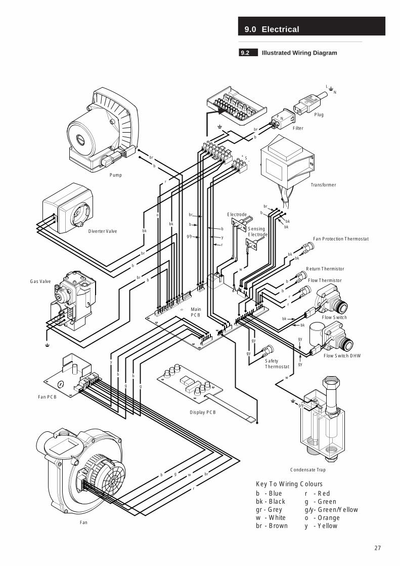
9.2 Illustrated Wiring Diagram
br
b
bk
br
b
brb
Pump
Diverter Valve
Gas Valve
Fan PCB
y
b
g
b
g
b g w br
Fan
Display PCB
Condensate Trap
SafetyThermostat
g/y
w
gy
gy
r
Flow Switch DHW
Flow Switch
Flow Thermistor
Return Thermistor
Fan Protection Thermostat
gy
gy
bk
bk
rb
b
bkbk
Transformer
Electrode
SensingElectrode
w
bkbk
br
bo
r
bk
br
b
g/y
b
y
r
MainPCB
+ S-
N
L
Filter
Plug
r
NP
br
b
Key To Wiring Colours b - Bluebk - Blackgr - Greyw - Whitebr - Brown
r - Redg - Greeng/y- Green/Yellowo - Orangey - Yellow
10.0 Commissioning the Boiler
28
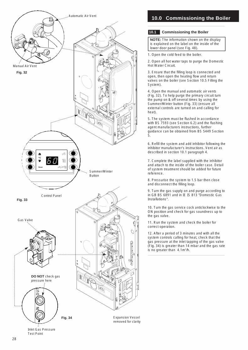
10.1 Commissioning the Boiler
NOTE: The information shown on the displayis explained on the label on the inside of thelower door panel (see Fig. 48).
1. Open the cold feed to the boiler.
2. Open all hot water taps to purge the DomesticHot Water Circuit.
3. Ensure that the filling loop is connected andopen, then open the heating flow and returnvalves on the boiler (see Section 10.5 Filling theSystem).
4. Open the manual and automatic air vents (Fig. 32). To help purge the primary circuit turnthe pump on & off several times by using theSummer/Winter button (Fig. 33) (ensure allexternal controls are turned on and calling forheat).
5. The system must be flushed in accordancewith BS 7593 (see Section 6.2) and the flushingagent manufacturers instructions, furtherguidance can be obtained from BS 5449 Section5.
6. Refill the system and add inhibitor following theinhibitor manufacturer’s instructions. Vent air asdescribed in section 10.1 paragraph 4.
7. Complete the label supplied with the inhibitorand attach to the inside of the boiler case. Detailof system treatment should be added for futurereference.
8. Pressurise the system to 1.5 bar then closeand disconnect the filling loop.
9. Turn the gas supply on and purge according toin GB BS 6891 and in IE IS 813 "Domestic GasInstallations".
10. Turn the gas service cock anticlockwise to theON position and check for gas soundness up tothe gas valve.
11. Run the system and check the boiler forcorrect operation.
12. After a period of 3 minutes and with all thesystem controls calling for heat, check that thegas pressure at the inlet tapping of the gas valve (Fig. 34) is greater than 14 mbar and the gas rateis no greater than 4.1m3/h.
INO
UT
Co
Reset
Summer/WinterButton
Control PanelFig. 33
Automatic Air Vent
Manual Air Vent
Fig. 32
Gas Valve
DO NOT check gaspressure here
Inlet Gas PressureTest Point
Fig. 34 Expansion Vesselremoved for clarity
10.0 Commissioning the Boiler
29
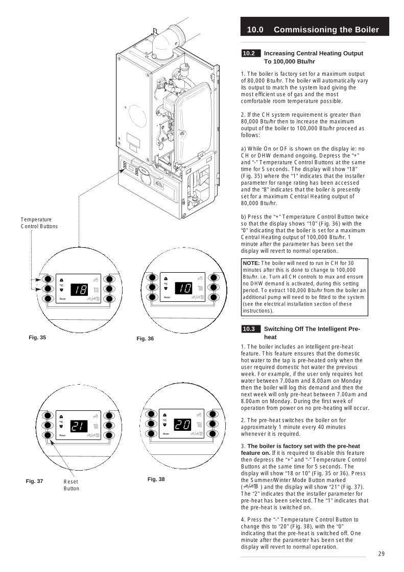
10.2 Increasing Central Heating Output To 100,000 Btu/hr
1. The boiler is factory set for a maximum outputof 80,000 Btu/hr. The boiler will automatically varyits output to match the system load giving themost efficient use of gas and the mostcomfortable room temperature possible.
2. If the CH system requirement is greater than80,000 Btu/hr then to increase the maximumoutput of the boiler to 100,000 Btu/hr proceed asfollows:
a) While On or OF is shown on the display ie: noCH or DHW demand ongoing. Depress the “+”and “-” Temperature Control Buttons at the sametime for 5 seconds. The display will show “18”(Fig. 35) where the “1” indicates that the installerparameter for range rating has been accessedand the “8” indicates that the boiler is presentlyset for a maximum Central Heating output of80,000 Btu/hr.
b) Press the “+” Temperature Control Button twiceso that the display shows “10” (Fig. 36) with the“0” indicating that the boiler is set for a maximumCentral Heating output of 100,000 Btu/hr. 1minute after the parameter has been set thedisplay will revert to normal operation.
NOTE: The boiler will need to run in CH for 30minutes after this is done to change to 100,000Btu/hr. i.e. Turn all CH controls to max and ensureno DHW demand is activated, during this settingperiod. To extract 100,000 Btu/hr from the boiler anadditional pump will need to be fitted to the system(see the electrical installation section of theseinstructions).
10.3 Switching Off The Intelligent Pre-heat
1. The boiler includes an intelligent pre-heatfeature. This feature ensures that the domestichot water to the tap is pre-heated only when theuser required domestic hot water the previousweek. For example, if the user only requires hotwater between 7.00am and 8.00am on Mondaythen the boiler will log this demand and then thenext week will only pre-heat between 7.00am and8.00am on Monday. During the first week ofoperation from power on no pre-heating will occur.
2. The pre-heat switches the boiler on forapproximately 1 minute every 40 minuteswhenever it is required.
3. The boiler is factory set with the pre-heatfeature on. If it is required to disable this featurethen depress the “+” and “-” Temperature ControlButtons at the same time for 5 seconds. Thedisplay will show “18 or 10” (Fig. 35 or 36). Pressthe Summer/Winter Mode Button marked ( ) and the display will show “21” (Fig. 37).The “2” indicates that the installer parameter forpre-heat has been selected. The “1” indicates thatthe pre-heat is switched on.
4. Press the “-” Temperature Control Button tochange this to “20” (Fig. 38), with the “0”indicating that the pre-heat is switched off. Oneminute after the parameter has been set thedisplay will revert to normal operation.
Co
Reset
Co
Reset
Co
Reset
Co
Reset
Fig. 35 Fig. 36
Fig. 37 Fig. 38
TemperatureControl Buttons
ResetButton
10.0 Commissioning the Boiler
30
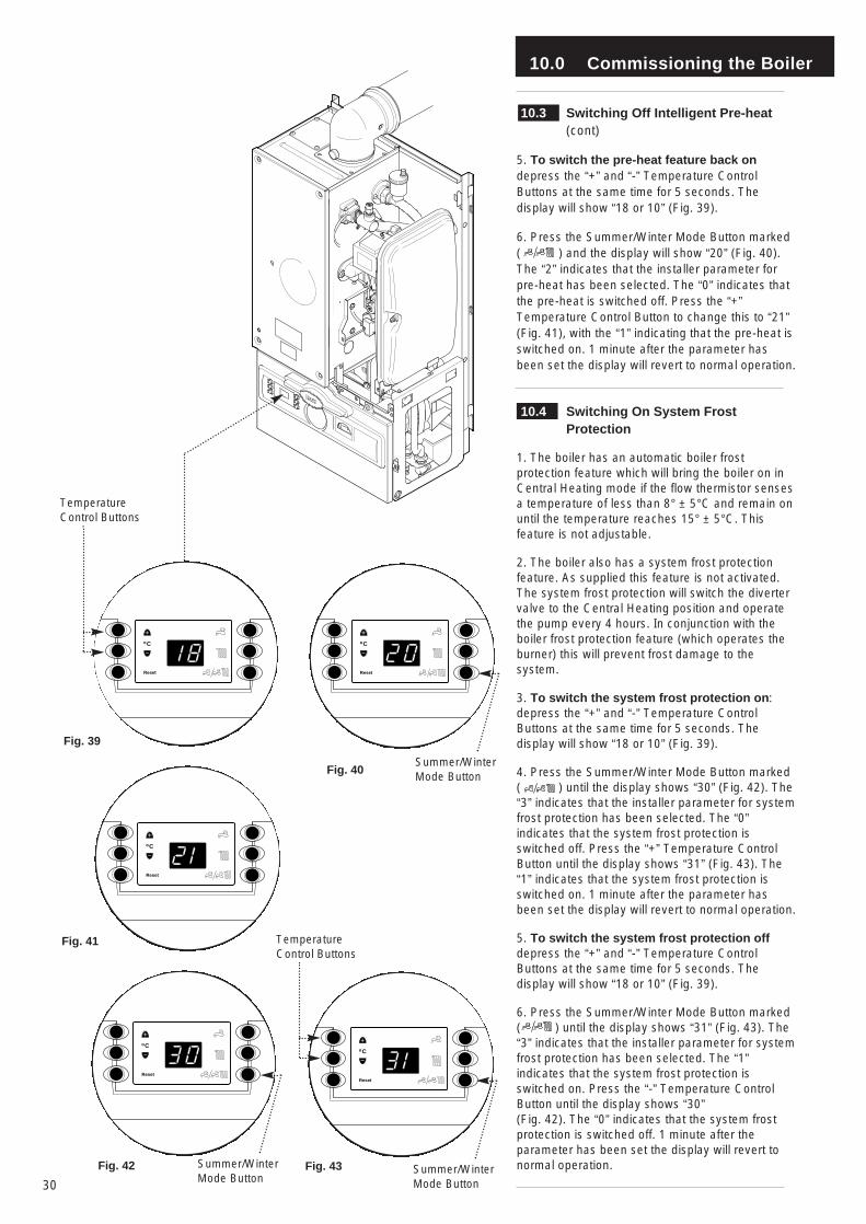
10.3 Switching Off Intelligent Pre-heat (cont)
5. To switch the pre-heat feature back ondepress the “+” and “-” Temperature ControlButtons at the same time for 5 seconds. Thedisplay will show “18 or 10” (Fig. 39).
6. Press the Summer/Winter Mode Button marked ( ) and the display will show “20” (Fig. 40).The “2” indicates that the installer parameter forpre-heat has been selected. The “0” indicates thatthe pre-heat is switched off. Press the “+”Temperature Control Button to change this to “21”(Fig. 41), with the “1” indicating that the pre-heat isswitched on. 1 minute after the parameter hasbeen set the display will revert to normal operation.
10.4 Switching On System Frost Protection
1. The boiler has an automatic boiler frostprotection feature which will bring the boiler on inCentral Heating mode if the flow thermistor sensesa temperature of less than 8° ± 5°C and remain onuntil the temperature reaches 15° ± 5°C. Thisfeature is not adjustable.
2. The boiler also has a system frost protectionfeature. As supplied this feature is not activated.The system frost protection will switch the divertervalve to the Central Heating position and operatethe pump every 4 hours. In conjunction with theboiler frost protection feature (which operates theburner) this will prevent frost damage to thesystem.
3. To switch the system frost protection on:depress the “+” and “-” Temperature ControlButtons at the same time for 5 seconds. Thedisplay will show “18 or 10” (Fig. 39).
4. Press the Summer/Winter Mode Button marked ( ) until the display shows “30” (Fig. 42). The“3” indicates that the installer parameter for systemfrost protection has been selected. The “0”indicates that the system frost protection isswitched off. Press the “+” Temperature ControlButton until the display shows “31” (Fig. 43). The“1” indicates that the system frost protection isswitched on. 1 minute after the parameter hasbeen set the display will revert to normal operation.
5. To switch the system frost protection offdepress the “+” and “-” Temperature ControlButtons at the same time for 5 seconds. Thedisplay will show “18 or 10” (Fig. 39).
6. Press the Summer/Winter Mode Button marked ( ) until the display shows “31” (Fig. 43). The“3” indicates that the installer parameter for systemfrost protection has been selected. The “1”indicates that the system frost protection isswitched on. Press the “-” Temperature ControlButton until the display shows “30” (Fig. 42). The “0” indicates that the system frostprotection is switched off. 1 minute after theparameter has been set the display will revert tonormal operation.
Co
Reset
Co
Reset
Fig. 42
Co
Reset
TemperatureControl Buttons
Fig. 39
Co
Reset
Fig. 40
Co
Reset
Fig. 41
Fig. 43
Summer/WinterMode Button
Summer/WinterMode Button
TemperatureControl Buttons
Summer/WinterMode Button
10.0 Commissioning the Boiler
31
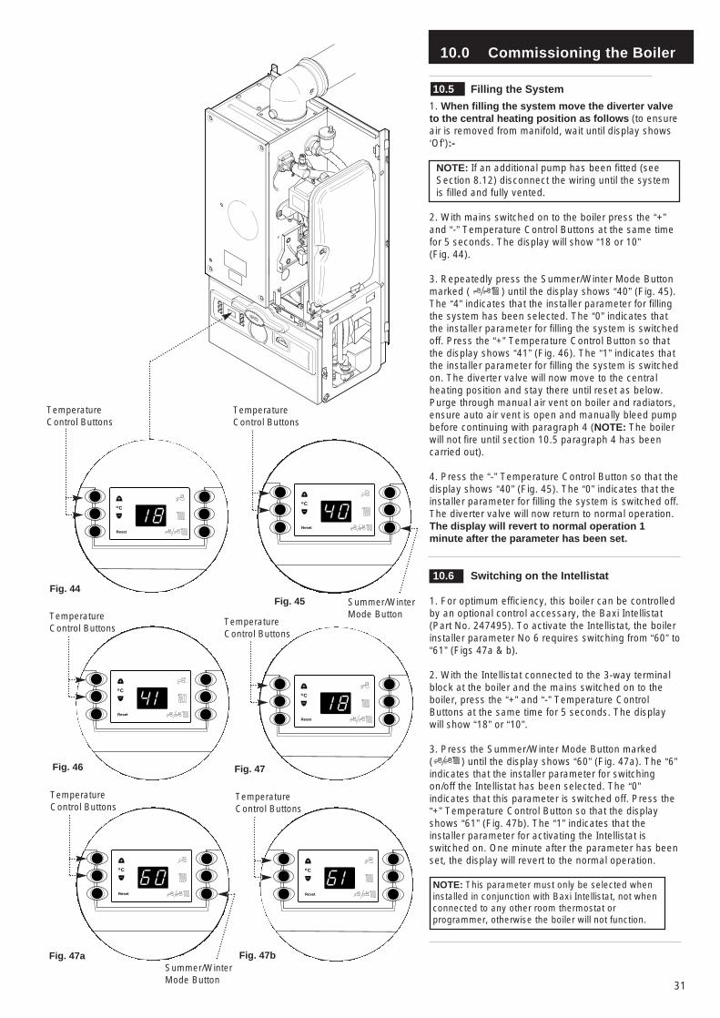
10.5 Filling the System
1. When filling the system move the diverter valveto the central heating position as follows (to ensureair is removed from manifold, wait until display shows‘Of’):-
NOTE: If an additional pump has been fitted (seeSection 8.12) disconnect the wiring until the systemis filled and fully vented.
2. With mains switched on to the boiler press the “+”and “-” Temperature Control Buttons at the same timefor 5 seconds. The display will show “18 or 10” (Fig. 44).
3. Repeatedly press the Summer/Winter Mode Buttonmarked ( ) until the display shows “40” (Fig. 45).The “4” indicates that the installer parameter for fillingthe system has been selected. The “0” indicates thatthe installer parameter for filling the system is switchedoff. Press the “+” Temperature Control Button so thatthe display shows “41” (Fig. 46). The “1” indicates thatthe installer parameter for filling the system is switchedon. The diverter valve will now move to the centralheating position and stay there until reset as below.Purge through manual air vent on boiler and radiators,ensure auto air vent is open and manually bleed pumpbefore continuing with paragraph 4 (NOTE: The boilerwill not fire until section 10.5 paragraph 4 has beencarried out).
4. Press the “-” Temperature Control Button so that thedisplay shows “40” (Fig. 45). The “0” indicates that theinstaller parameter for filling the system is switched off.The diverter valve will now return to normal operation.The display will revert to normal operation 1minute after the parameter has been set.
10.6 Switching on the Intellistat
1. For optimum efficiency, this boiler can be controlledby an optional control accessary, the Baxi Intellistat(Part No. 247495). To activate the Intellistat, the boilerinstaller parameter No 6 requires switching from “60” to“61” (Figs 47a & b).
2. With the Intellistat connected to the 3-way terminalblock at the boiler and the mains switched on to theboiler, press the “+” and “-” Temperature ControlButtons at the same time for 5 seconds. The displaywill show “18” or “10”.
3. Press the Summer/Winter Mode Button marked ( ) until the display shows “60” (Fig. 47a). The “6”indicates that the installer parameter for switchingon/off the Intellistat has been selected. The “0”indicates that this parameter is switched off. Press the“+” Temperature Control Button so that the displayshows “61” (Fig. 47b). The “1” indicates that theinstaller parameter for activating the Intellistat isswitched on. One minute after the parameter has beenset, the display will revert to the normal operation.
NOTE: This parameter must only be selected wheninstalled in conjunction with Baxi Intellistat, not whenconnected to any other room thermostat orprogrammer, otherwise the boiler will not function.
Co
Reset
Co
Reset
Co
Reset
TemperatureControl Buttons
Fig. 44Fig. 45 Summer/Winter
Mode ButtonTemperatureControl Buttons
Fig. 46
Co
Reset
TemperatureControl Buttons
Fig. 47
TemperatureControl Buttons
Co
Reset
Co
Reset
Fig. 47a Fig. 47b
TemperatureControl Buttons
TemperatureControl Buttons
Summer/WinterMode Button
11.0 Fitting the Outer Case
32
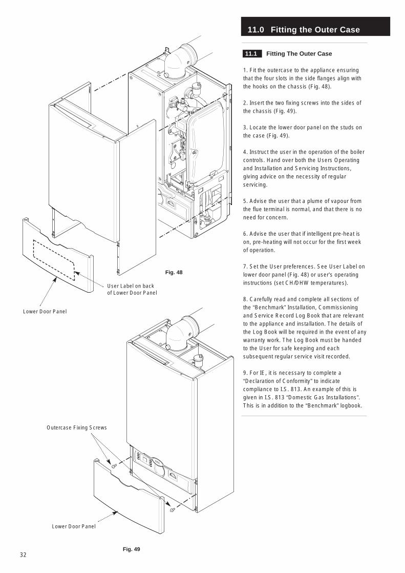
11.1 Fitting The Outer Case
1. Fit the outercase to the appliance ensuringthat the four slots in the side flanges align withthe hooks on the chassis (Fig. 48).
2. Insert the two fixing screws into the sides ofthe chassis (Fig. 49).
3. Locate the lower door panel on the studs onthe case (Fig. 49).
4. Instruct the user in the operation of the boilercontrols. Hand over both the Users Operatingand Installation and Servicing Instructions,giving advice on the necessity of regularservicing.
5. Advise the user that a plume of vapour fromthe flue terminal is normal, and that there is noneed for concern.
6. Advise the user that if intelligent pre-heat ison, pre-heating will not occur for the first weekof operation.
7. Set the User preferences. See User Label onlower door panel (Fig. 48) or user’s operatinginstructions (set CH/DHW temperatures).
8. Carefully read and complete all sections ofthe “Benchmark” Installation, Commissioningand Service Record Log Book that are relevantto the appliance and installation. The details ofthe Log Book will be required in the event of anywarranty work. The Log Book must be handedto the User for safe keeping and eachsubsequent regular service visit recorded.
9. For IE, it is necessary to complete a“Declaration of Conformity” to indicatecompliance to I.S. 813. An example of this isgiven in I.S. 813 “Domestic Gas Installations”.This is in addition to the “Benchmark” logbook.
Fig. 48
Fig. 49
Lower Door Panel
Outercase Fixing Screws
Lower Door Panel
User Label on backof Lower Door Panel
12.0 Servicing the Boiler
33
12.1 Annual Servicing
IMPORTANT: When servicing ensure that both thegas and electrical supplies to the boiler are isolatedbefore any work is started.
Hazardous materials are not used in theconstruction of Baxi products, however reasonablecare during service is recommended.
1. For reasons of safety and economy, it isrecommended that the boiler is serviced annually.
2. After servicing, complete the relevant sectionof the “Benchmark” Installation, Commissioningand Service Record Log Book. This should be inthe possession of the user.
3. Ensure that the boiler is cool.
4. Ensure that both the gas and electricalsupplies to the boiler are isolated.
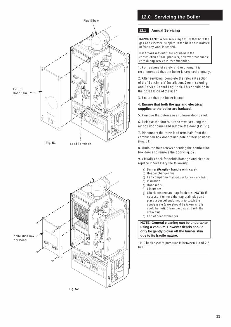
5. Remove the outercase and lower door panel.
6. Release the four 1/4 turn screws securing theair box door panel and remove the door (Fig. 51).
7. Disconnect the three lead terminals from thecombustion box door taking note of their positions(Fig. 51).
8. Undo the four screws securing the combustionbox door and remove the door (Fig. 52).
9. Visually check for debris/damage and clean orreplace if necessary the following:
a) Burner (Fragile - handle with care).b) Heat exchanger fins.c) Fan compartment (Check also for condensate leaks).
d) Insulation.e) Door seals.f) Electrodes.g) Check condensate trap for debris. NOTE: If
necessary remove the trap drain plug and place a vessel underneath to catch the condensate (care should be taken as this could be hot). Clean the trap and refit the drain plug.
h) Top of heat exchanger.
NOTE: General cleaning can be undertakenusing a vacuum. However debris shouldonly be gently blown off the burner skindue to its fragile nature.
10. Check system pressure is between 1 and 2.5bar.
Flue Elbow
Lead TerminalsFig. 51
Air BoxDoor Panel
Fig. 52
Combustion BoxDoor Panel
12.0 Servicing the Boiler
34
12.1 Annual Servicing (Cont)
NOTE: The information shown on the displayis explained on the label on the inside of thelower door panel (see Fig. 48).
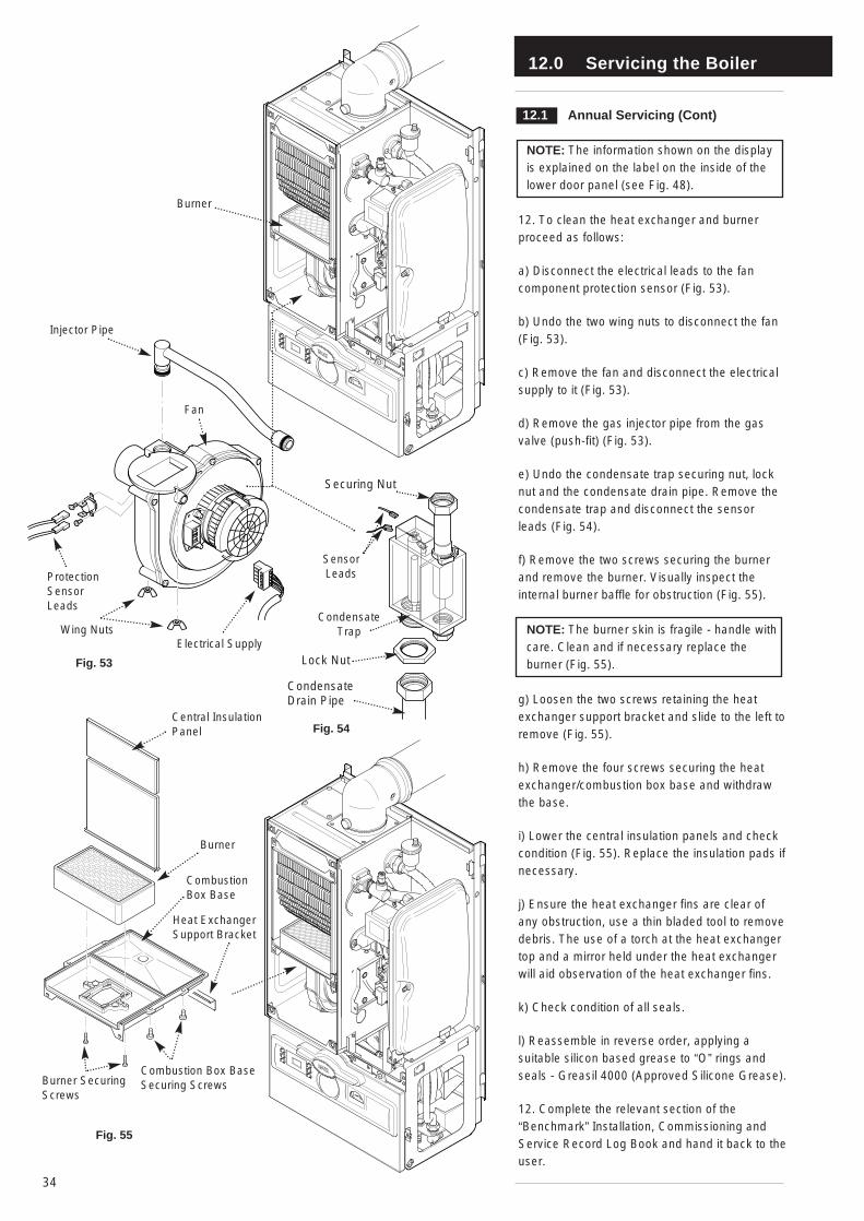
12. To clean the heat exchanger and burnerproceed as follows:
a) Disconnect the electrical leads to the fancomponent protection sensor (Fig. 53).
b) Undo the two wing nuts to disconnect the fan(Fig. 53).
c) Remove the fan and disconnect the electricalsupply to it (Fig. 53).
d) Remove the gas injector pipe from the gasvalve (push-fit) (Fig. 53).
e) Undo the condensate trap securing nut, locknut and the condensate drain pipe. Remove thecondensate trap and disconnect the sensorleads (Fig. 54).
f) Remove the two screws securing the burnerand remove the burner. Visually inspect theinternal burner baffle for obstruction (Fig. 55).
NOTE: The burner skin is fragile - handle withcare. Clean and if necessary replace theburner (Fig. 55).
g) Loosen the two screws retaining the heatexchanger support bracket and slide to the left toremove (Fig. 55).
h) Remove the four screws securing the heatexchanger/combustion box base and withdrawthe base.
i) Lower the central insulation panels and checkcondition (Fig. 55). Replace the insulation pads ifnecessary.
j) Ensure the heat exchanger fins are clear ofany obstruction, use a thin bladed tool to removedebris. The use of a torch at the heat exchangertop and a mirror held under the heat exchangerwill aid observation of the heat exchanger fins.
k) Check condition of all seals.
l) Reassemble in reverse order, applying asuitable silicon based grease to “O” rings andseals - Greasil 4000 (Approved Silicone Grease).
12. Complete the relevant section of the“Benchmark” Installation, Commissioning andService Record Log Book and hand it back to theuser.
Fig. 53
Burner
Fig. 54
Electrical Supply
Fig. 55
Wing Nuts
ProtectionSensorLeads
Fan
Injector Pipe
Central InsulationPanel
Burner
CombustionBox Base
Heat ExchangerSupport Bracket
Combustion Box BaseSecuring ScrewsBurner Securing
Screws
Lock Nut
Condensate Trap
CondensateDrain Pipe
Securing Nut
SensorLeads
13.0 Changing Components
35
13.1 Changing Components
IMPORTANT: When changing componentsensure that both the gas and electrical supplies tothe boiler are isolated before any work is started.
Hazardous materials are not used in theconstruction of Baxi products, howeverreasonable care during service is recommended.
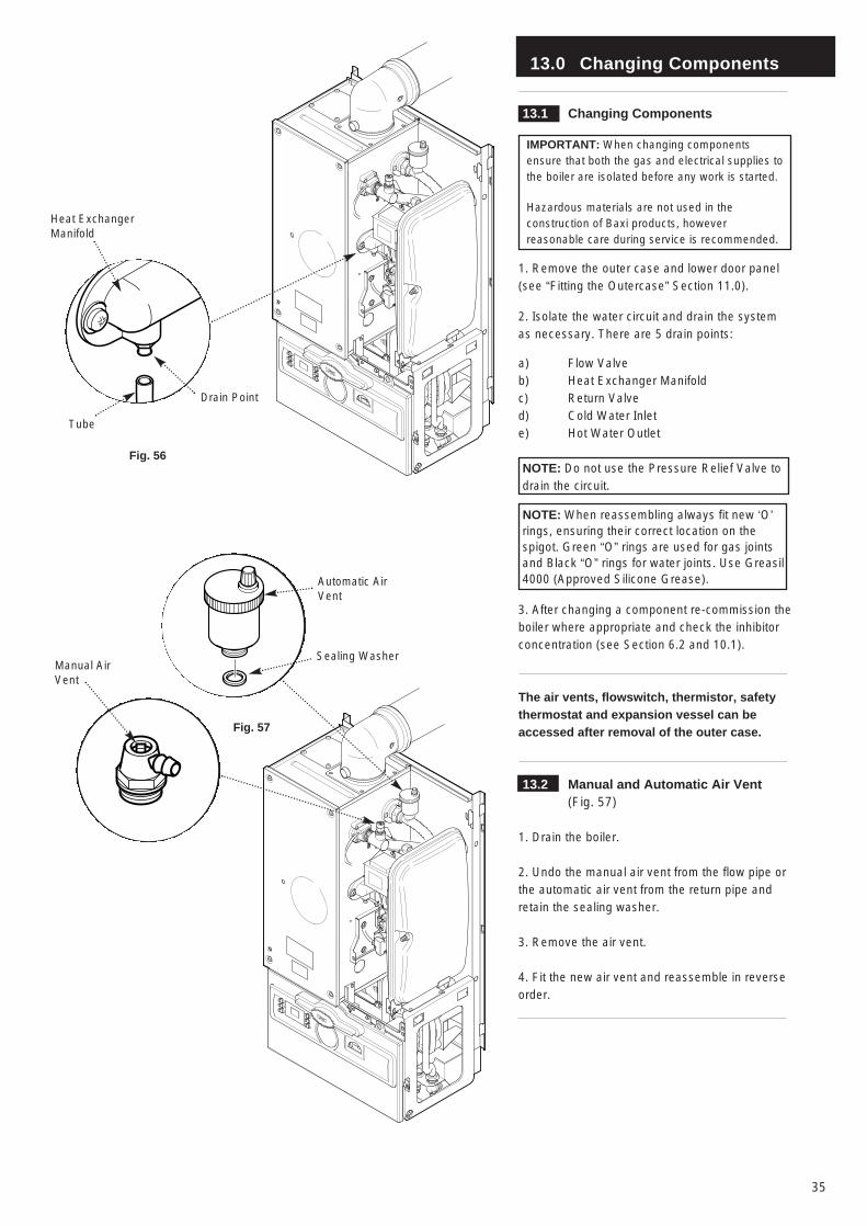
1. Remove the outer case and lower door panel(see “Fitting the Outercase” Section 11.0).
2. Isolate the water circuit and drain the systemas necessary. There are 5 drain points:
a) Flow Valveb) Heat Exchanger Manifoldc) Return Valved) Cold Water Inlete) Hot Water Outlet
NOTE: Do not use the Pressure Relief Valve todrain the circuit.
NOTE: When reassembling always fit new ‘O’rings, ensuring their correct location on thespigot. Green “O” rings are used for gas jointsand Black “O” rings for water joints. Use Greasil4000 (Approved Silicone Grease).
3. After changing a component re-commission theboiler where appropriate and check the inhibitorconcentration (see Section 6.2 and 10.1).
The air vents, flowswitch, thermistor, safetythermostat and expansion vessel can beaccessed after removal of the outer case.
13.2 Manual and Automatic Air Vent (Fig. 57)
1. Drain the boiler.
2. Undo the manual air vent from the flow pipe orthe automatic air vent from the return pipe andretain the sealing washer.
3. Remove the air vent.
4. Fit the new air vent and reassemble in reverseorder.
Fig. 56
Heat ExchangerManifold
Drain Point
Tube
Fig. 57
Automatic AirVent
Sealing WasherManual AirVent
13.0 Changing Components
36
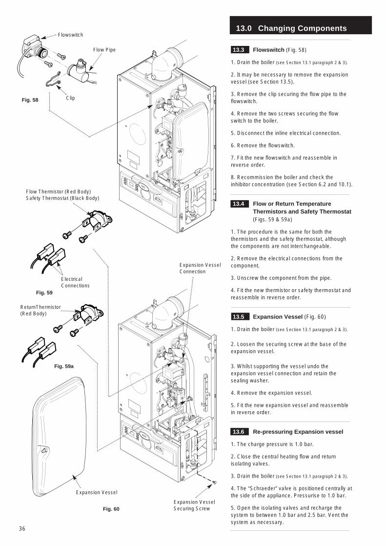
13.3 Flowswitch (Fig. 58)
1. Drain the boiler (see Section 13.1 paragraph 2 & 3).
2. It may be necessary to remove the expansionvessel (see Section 13.5).
3. Remove the clip securing the flow pipe to theflowswitch.
4. Remove the two screws securing the flowswitch to the boiler.
5. Disconnect the inline electrical connection.
6. Remove the flowswitch.
7. Fit the new flowswitch and reassemble inreverse order.
8. Recommission the boiler and check theinhibitor concentration (see Section 6.2 and 10.1).
13.4 Flow or Return Temperature Thermistors and Safety Thermostat(Figs. 59 & 59a)
1. The procedure is the same for both thethermistors and the safety thermostat, althoughthe components are not interchangeable.
2. Remove the electrical connections from thecomponent.
3. Unscrew the component from the pipe.
4. Fit the new thermistor or safety thermostat andreassemble in reverse order.
13.5 Expansion Vessel (Fig. 60)
1. Drain the boiler (see Section 13.1 paragraph 2 & 3).
2. Loosen the securing screw at the base of theexpansion vessel.
3. Whilst supporting the vessel undo theexpansion vessel connection and retain thesealing washer.
4. Remove the expansion vessel.
5. Fit the new expansion vessel and reassemblein reverse order.
13.6 Re-pressuring Expansion vessel
1. The charge pressure is 1.0 bar.
2. Close the central heating flow and returnisolating valves.
3. Drain the boiler (see Section 13.1 paragraph 2 & 3).
4. The “Schraeder” valve is positioned centrally atthe side of the appliance. Pressurise to 1.0 bar.
5. Open the isolating valves and recharge thesystem to between 1.0 bar and 2.5 bar. Vent thesystem as necessary.
Fig. 58
Flowswitch
Clip
Fig. 59
Fig. 60
Flow Pipe
Electrical Connections
Expansion Vessel
Expansion VesselSecuring Screw
Flow Thermistor (Red Body)Safety Thermostat (Black Body)
Expansion VesselConnection
ReturnThermistor(Red Body)
Fig. 59a
13.0 Changing Components
37
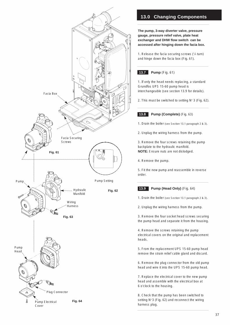
The pump, 3-way diverter valve, pressuregauge, pressure relief valve, plate heatexchanger and DHW flow switch can beaccessed after hinging down the facia box.
1. Release the facia securing screws (1/4 turn)and hinge down the facia box (Fig. 61).
13.7 Pump (Fig. 61)
1. If only the head needs replacing, a standardGrundfos UPS 15-60 pump head isinterchangeable (see section 13.9 for details).
2. This must be switched to setting No 3 (Fig. 62).
13.8 Pump (Complete) (Fig. 63)
1. Drain the boiler (see Section 13.1 paragraph 2 & 3).
2. Unplug the wiring harness from the pump.
3. Remove the four screws retaining the pumpbackplate to the hydraulic manifold. NOTE: Ensure nuts are not dislodged.
4. Remove the pump.
5. Fit the new pump and reassemble in reverseorder.
13.9 Pump (Head Only) (Fig. 64)
1. Drain the boiler (see Section 13.1 paragraph 2 & 3).
2. Unplug the wiring harness from the pump.
3. Remove the four socket head screws securingthe pump head and separate it from the housing.
4. Remove the screws retaining the pumpelectrical covers on the original and replacementheads.
5. From the replacement UPS 15-60 pump headremove the strain relief cable gland and discard.
6. Remove the plug connector from the old pumphead and wire it into the UPS 15-60 pump head.
7. Replace the electrical cover to the new pumphead and assemble with the electrical box at 6 o’clock to the housing.
8. Check that the pump has been switched tosetting No 3 (Fig. 62) and reconnect the wiringharness plug.
Fig. 61
Facia Box
Fig. 63
Facia SecuringScrews
Fig. 62
Pump Setting
Fig. 64
Plug Connector
HydraulicManifold
WiringHarness
Pump
Pump Head
Pump ElectricalCover
13.0 Changing Components
38
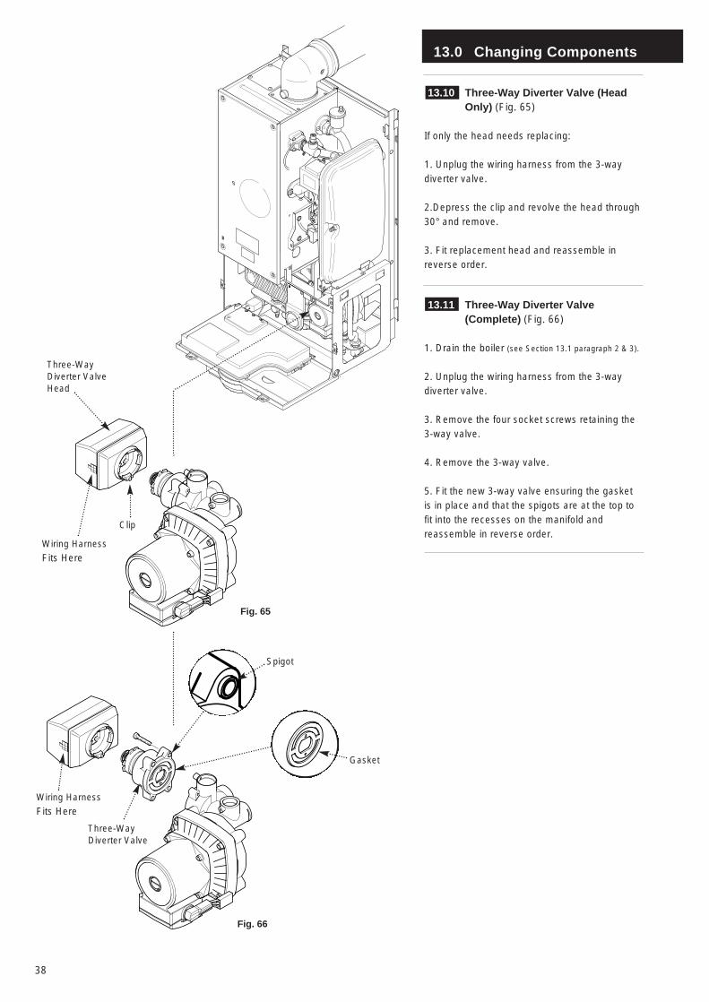
13.10 Three-Way Diverter Valve (Head Only) (Fig. 65)
If only the head needs replacing:
1. Unplug the wiring harness from the 3-waydiverter valve.
2.Depress the clip and revolve the head through30° and remove.
3. Fit replacement head and reassemble inreverse order.
13.11 Three-Way Diverter Valve (Complete) (Fig. 66)
1. Drain the boiler (see Section 13.1 paragraph 2 & 3).
2. Unplug the wiring harness from the 3-waydiverter valve.
3. Remove the four socket screws retaining the3-way valve.
4. Remove the 3-way valve.
5. Fit the new 3-way valve ensuring the gasketis in place and that the spigots are at the top tofit into the recesses on the manifold andreassemble in reverse order.
Fig. 65
Wiring Harness
Fits Here
Fig. 66
Clip
Three-WayDiverter ValveHead
Wiring Harness
Fits Here
Three-WayDiverter Valve
Spigot
Gasket
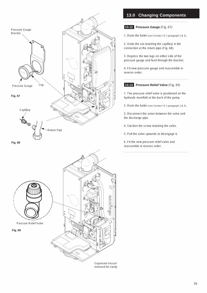
13.0 Changing Components
39
13.12 Pressure Gauge (Fig. 67)
1. Drain the boiler (see Section 13.1 paragraph 2 & 3).
2. Undo the nut retaining the capillary in theconnection at the return pipe (Fig. 68).
3. Depress the two lugs on either side of thepressure gauge and feed through the bracket.
4. Fit new pressure gauge and reassemble inreverse order.
13.13 Pressure Relief Valve (Fig. 69)
1. The pressure relief valve is positioned on thehydraulic manifold at the back of the pump.
2. Drain the boiler (see Section 13.1 paragraph 2 & 3).
3. Disconnect the union between the valve andthe discharge pipe.
4. Slacken the screw retaining the valve.
5. Pull the valve upwards to disengage it.
6. Fit the new pressure relief valve andreassemble in reverse order.
Fig. 67
LugPressure Gauge
Pressure GaugeBracket
Fig. 68
Capillary
Return Pipe
Fig. 69
Pressure Relief Valve
Expansion Vesselremoved for clarity
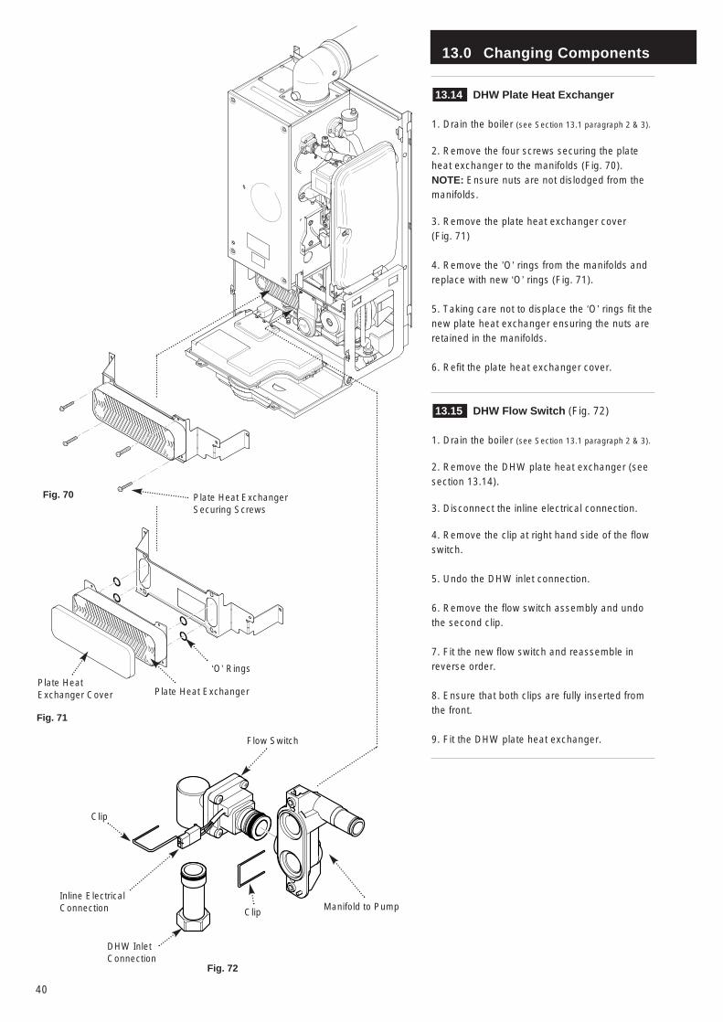
13.0 Changing Components
40
13.14 DHW Plate Heat Exchanger
1. Drain the boiler (see Section 13.1 paragraph 2 & 3).
2. Remove the four screws securing the plateheat exchanger to the manifolds (Fig. 70).NOTE: Ensure nuts are not dislodged from themanifolds.
3. Remove the plate heat exchanger cover (Fig. 71)
4. Remove the ’O’ rings from the manifolds andreplace with new ‘O’ rings (Fig. 71).
5. Taking care not to displace the ‘O’ rings fit thenew plate heat exchanger ensuring the nuts areretained in the manifolds.
6. Refit the plate heat exchanger cover.
13.15 DHW Flow Switch (Fig. 72)
1. Drain the boiler (see Section 13.1 paragraph 2 & 3).
2. Remove the DHW plate heat exchanger (seesection 13.14).
3. Disconnect the inline electrical connection.
4. Remove the clip at right hand side of the flowswitch.
5. Undo the DHW inlet connection.
6. Remove the flow switch assembly and undothe second clip.
7. Fit the new flow switch and reassemble inreverse order.
8. Ensure that both clips are fully inserted fromthe front.
9. Fit the DHW plate heat exchanger.
Fig. 70 Plate Heat ExchangerSecuring Screws
Fig. 71
Plate HeatExchanger Cover
‘O’ Rings
Fig. 72
Inline ElectricalConnection
Clip
Flow Switch
Manifold to PumpClip
DHW InletConnection
Plate Heat Exchanger
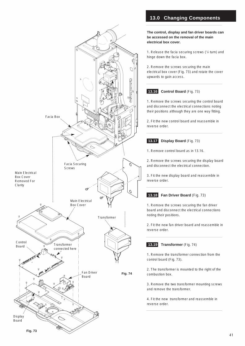
13.0 Changing Components
41
The control, display and fan driver boards canbe accessed on the removal of the mainelectrical box cover.
1. Release the facia securing screws (1/4 turn) andhinge down the facia box.
2. Remove the screws securing the mainelectrical box cover (Fig. 73) and rotate the coverupwards to gain access.
13.16 Control Board (Fig. 73)
1. Remove the screws securing the control boardand disconnect the electrical connections notingtheir positions although they are one way fitting.
2. Fit the new control board and reassemble inreverse order.
13.17 Display Board (Fig. 73)
1. Remove control board as in 13.16.
2. Remove the screws securing the display boardand disconnect the electrical connection.
3. Fit the new display board and reassemble inreverse order.
13.18 Fan Driver Board (Fig. 73)
1. Remove the screws securing the fan driverboard and disconnect the electrical connectionsnoting their positions.
2. Fit the new fan driver board and reassemble inreverse order.
13.19 Transformer (Fig. 74)
1. Remove the transformer connection from thecontrol board (Fig. 73).
2. The transformer is mounted to the right of thecombustion box.
3. Remove the two transformer mounting screwsand remove the transformer.
4. Fit the new transformer and reassemble inreverse order.
Fig. 73
Fig. 74
Main ElectricalBox Cover
ControlBoard Transformer
connected here
Transformer
Fan DriverBoard
DisplayBoard
Facia Box
Facia SecuringScrews
Main ElectricalBox CoverRemoved ForClarity

13.0 Changing Components
42
The fan and venturi, gas valve, injector pipe,condensate trap, fan protection thermostat,spark and sensing electrodes can beaccessed and changed on the removal of theairbox door panel.
1. Remove the airbox door panel by loosening thefour 1/4 turn screws (Fig. 75).
13.20 Spark and Sensing Electrodes (Fig. 76)
1. Disconnect the leads to the electrodes notingtheir positions (left to right):
Spark - Opaque LeadSpark - Opaque LeadSensing - White Lead
2. Remove the two screws securing each of theelectrodes to the combustion box door andremove the electrodes.
3. Fit the new electrodes and new gaskets,reassemble in reverse order, ensuring the sparkgap of 3.5mm ± 0.5mm is maintained.
13.21 Fan and Fan Protection Thermostat (Fig. 77)
1. Remove the electrical connections to the fanprotection thermostat on the fan.
2. Replacing the thermostat:- Unscrew thethermostat and replace with the new thermostat.Reassemble in reverse order.
3. Replacing the fan:- Remove the wing nutssecuring the fan to the base of the combustionbox.
4. Lower the fan and disconnect the electricalsupply from the right hand rear of the fan.Remove the fan/venturi assembly.
5. Remove the two screws securing the venturi tothe fan and remove the venturi together with thegasket.
6. Remove the fan protection thermostat and fix itto the new fan, together with the venturi andgasket.
7. Fit the new fan and reassemble in reverseorder.
The injector pipe, condensate trap and gasvalve can be changed after the removal of the fan.
Fig. 75
Air Box DoorPanel
Fig. 76
Fig. 77
CombustionBox Door
SensingElectrode
SparkElectrode
Fan ProtectionThermostat(Black Body)
Electrical SupplyWing Nuts
ProtectionThermostatLeads
Fan
Injector Pipe
SparkElectrodeLeads
Gaskets
Venturi
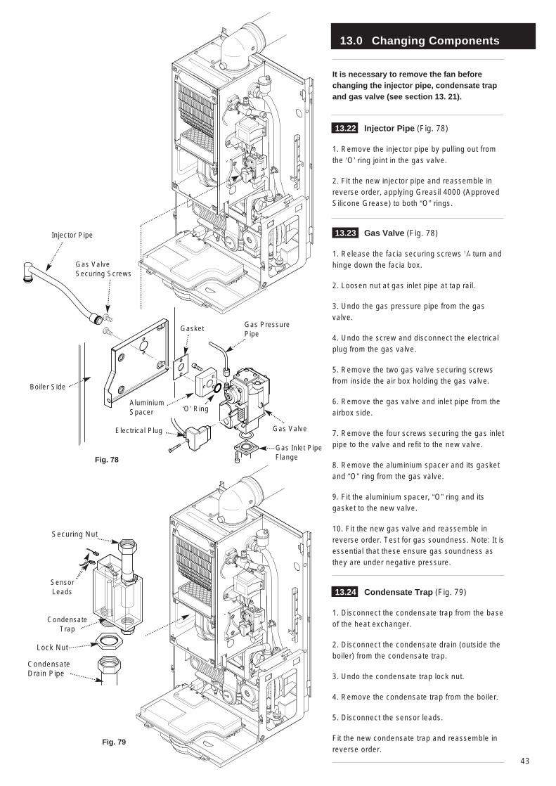
13.0 Changing Components
43
It is necessary to remove the fan beforechanging the injector pipe, condensate trapand gas valve (see section 13. 21).
13.22 Injector Pipe (Fig. 78)
1. Remove the injector pipe by pulling out fromthe ‘O’ ring joint in the gas valve.
2. Fit the new injector pipe and reassemble inreverse order, applying Greasil 4000 (ApprovedSilicone Grease) to both “O” rings.
13.23 Gas Valve (Fig. 78)
1. Release the facia securing screws 1/4 turn andhinge down the facia box.
2. Loosen nut at gas inlet pipe at tap rail.
3. Undo the gas pressure pipe from the gasvalve.
4. Undo the screw and disconnect the electricalplug from the gas valve.
5. Remove the two gas valve securing screwsfrom inside the air box holding the gas valve.
6. Remove the gas valve and inlet pipe from theairbox side.
7. Remove the four screws securing the gas inletpipe to the valve and refit to the new valve.
8. Remove the aluminium spacer and its gasketand “O” ring from the gas valve.
9. Fit the aluminium spacer, “O” ring and itsgasket to the new valve.
10. Fit the new gas valve and reassemble inreverse order. Test for gas soundness. Note: It isessential that these ensure gas soundness asthey are under negative pressure.
13.24 Condensate Trap (Fig. 79)
1. Disconnect the condensate trap from the baseof the heat exchanger.
2. Disconnect the condensate drain (outside theboiler) from the condensate trap.
3. Undo the condensate trap lock nut.
4. Remove the condensate trap from the boiler.
5. Disconnect the sensor leads.
Fit the new condensate trap and reassemble inreverse order.
Fig. 78
Injector Pipe
Gas ValveSecuring Screws
Boiler Side
Gas Valve
Gasket Gas PressurePipe
‘O’ RingAluminiumSpacer
Electrical Plug
Gas Inlet PipeFlange
Fig. 79
Lock Nut
Condensate Trap
CondensateDrain Pipe
Securing Nut
SensorLeads

13.0 Changing Components
44
The burner and heat exchanger can bechanged after removal of the combustion boxdoor. To change the heat exchanger, the fanand burner must be removed first (see section13. 21 & 13. 25).
1. Remove the combustion box door by undoingthe four 1/4 turn securing screws.
13.25 Burner (Fig. 80)
WARNING: The burner skin is fragile:(HANDLE WITH CARE)
1. Remove the two 8mm hex head screwssecuring the burner to the base of the combustionbox.
2. Remove the burner carefully from thecombustion box base, inspect gasket for damage,replace if necessary..
3. Fit the new burner and reassemble in reverseorder.
13.26 Heat Exchanger
1. Drain the boiler (see section 13.1 paragraph 2 & 3).
2. Remove the fan and condensate trap (seesection 13.21 and 13.24).
3. Undo the screws securing the flow switch andreturn connections. Remove the flow switch andreturn connection (Fig. 81).
4. Undo the screws securing the heat exchangermanifold and remove the manifold (Fig. 82).
5. Undo the M6 Hex Headed bolt on the left handside of the combustion box.
6. Undo the screws on the bracket supporting theheat exchanger and remove bracket.
7. Lift the heat exchanger assembly (Fig. 83) androtate the bottom upwards whilst pulling itforwards out of the airbox.
8. Fit the new heat exchanger and reassemble inreverse order.
9. Recommission the boiler and check theinhibitor concentration (see Section 6.2 and 10.1).
Fig. 80
SecuringScrews
Fig. 81
Burner
FlowSwitch
ReturnConnection
Heat ExchangerManifold
Fig. 82
Fig. 83
Heat ExchangerAssembly
Heat ExchangerSupport Bolt
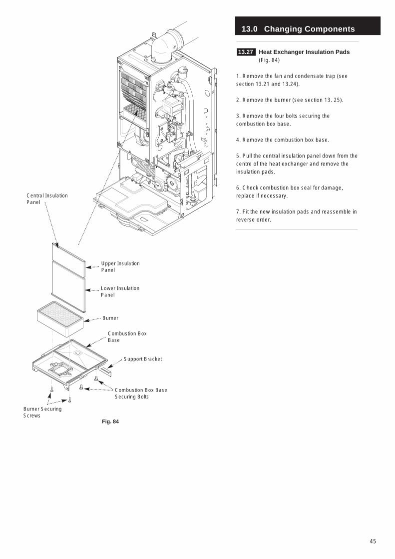
13.0 Changing Components
45
13.27 Heat Exchanger Insulation Pads (Fig. 84)
1. Remove the fan and condensate trap (seesection 13.21 and 13.24).
2. Remove the burner (see section 13. 25).
3. Remove the four bolts securing thecombustion box base.
4. Remove the combustion box base.
5. Pull the central insulation panel down from thecentre of the heat exchanger and remove theinsulation pads.
6. Check combustion box seal for damage,replace if necessary.
7. Fit the new insulation pads and reassemble inreverse order.
Fig. 84
Central InsulationPanel
Lower InsulationPanel
Upper InsulationPanel
Burner
Combustion BoxBase
Support Bracket
Burner SecuringScrews
Combustion Box BaseSecuring Bolts
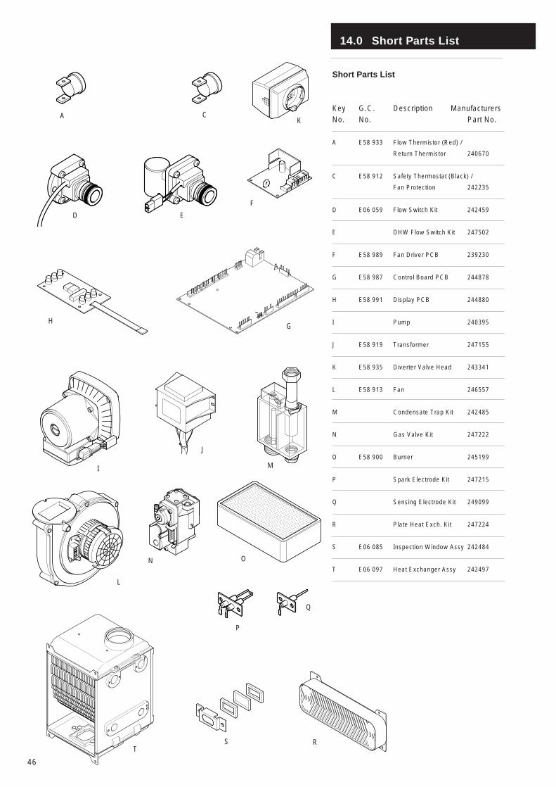
14.0 Short Parts List
46
Short Parts List
Key G.C. Description ManufacturersNo. No. Part No.
A E58 933 Flow Thermistor (Red) /
Return Thermistor 240670
C E58 912 Safety Thermostat (Black) /
Fan Protection 242235
D E06 059 Flow Switch Kit 242459
E DHW Flow Switch Kit 247502
F E58 989 Fan Driver PCB 239230
G E58 987 Control Board PCB 244878
H E58 991 Display PCB 244880
I Pump 240395
J E58 919 Transformer 247155
K E58 935 Diverter Valve Head 243341
L E58 913 Fan 246557
M Condensate Trap Kit 242485
N Gas Valve Kit 247222
O E58 900 Burner 245199
P Spark Electrode Kit 247215
Q Sensing Electrode Kit 249099
R Plate Heat Exch. Kit 247224
S E06 085 Inspection Window Assy 242484
T E06 097 Heat Exchanger Assy 242497
A
S
CK
D E
F
HG
I
J
M
ON
P
Q
R
L
T
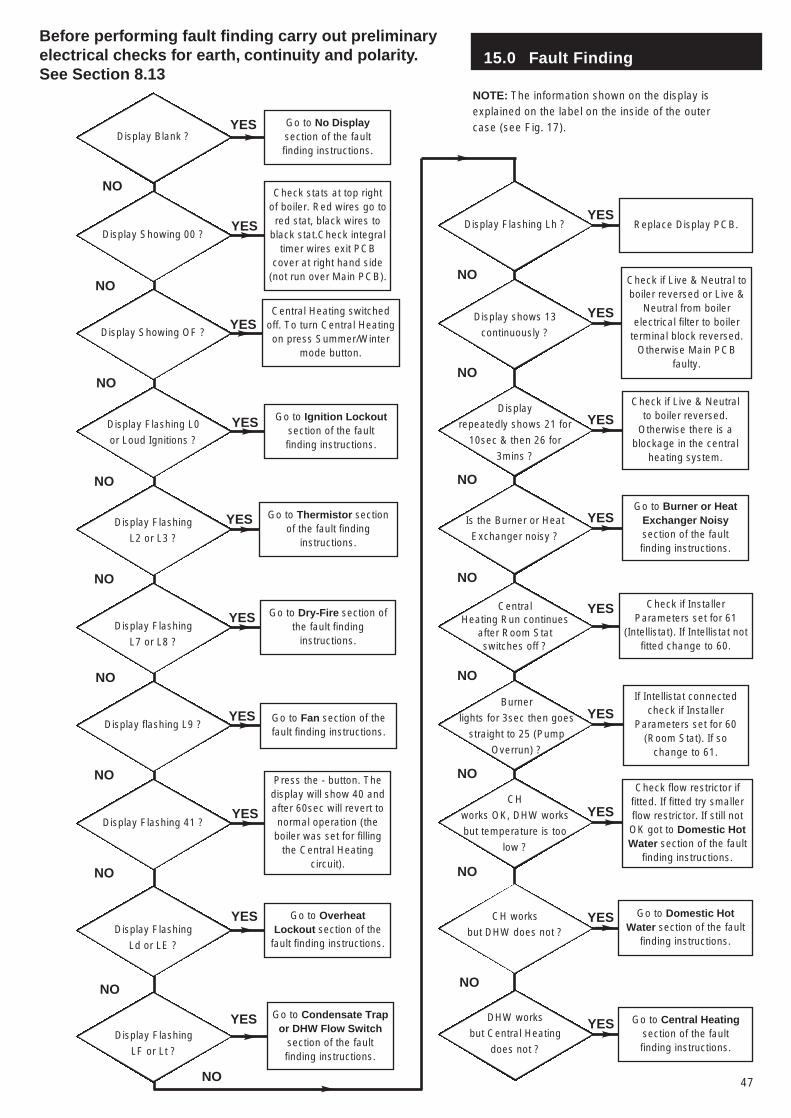
Display Blank ?
15.0 Fault Finding
47
Go to No Displaysection of the faultfinding instructions.
Display Showing 00 ?
Check stats at top rightof boiler. Red wires go tored stat, black wires to
black stat.Check integraltimer wires exit PCB
cover at right hand side(not run over Main PCB).
Display Showing OF ?
Central Heating switchedoff. To turn Central Heatingon press Summer/Winter
mode button.
Display Flashing L0
or Loud Ignitions ?
Go to Ignition Lockoutsection of the faultfinding instructions.
Display Flashing
L2 or L3 ?
Go to Thermistor sectionof the fault finding
instructions.
Display Flashing
L7 or L8 ?
Go to Dry-Fire section ofthe fault finding
instructions.
Display flashing L9 ?Go to Fan section of thefault finding instructions.
Display Flashing 41 ?
Press the - button. Thedisplay will show 40 andafter 60sec will revert tonormal operation (the
boiler was set for fillingthe Central Heating
circuit).
Display Flashing
Ld or LE ?
Go to OverheatLockout section of the
fault finding instructions.
NO
YES
Display Flashing Lh ? Replace Display PCB.
Display shows 13
continuously ?
Check if Live & Neutral toboiler reversed or Live &
Neutral from boilerelectrical filter to boiler
terminal block reversed.Otherwise Main PCB
faulty.
Display
repeatedly shows 21 for
10sec & then 26 for
3mins ?
Check if Live & Neutralto boiler reversed.
Otherwise there is ablockage in the central
heating system.
Is the Burner or Heat
Exchanger noisy ?
Go to Burner or HeatExchanger Noisysection of the faultfinding instructions.
Central Heating Run continues
after Room Stat switches off ?
Check if InstallerParameters set for 61
(Intellistat). If Intellistat notfitted change to 60.
Burner
lights for 3sec then goes
straight to 25 (Pump
Overrun) ?
If Intellistat connectedcheck if Installer
Parameters set for 60(Room Stat). If so
change to 61.
CH
works OK, DHW works
but temperature is too
low ?
Check flow restrictor iffitted. If fitted try smallerflow restrictor. If still notOK got to Domestic HotWater section of the fault
finding instructions.
CH works
but DHW does not ?
Go to Domestic HotWater section of the fault
finding instructions.
NO
NO
NO
NO
NO
NO
NO
YES
YES
YES
YES
YES
YES
YES
YES
YES
YES
YES
YES
YES
YES
YES
NO
NO
NO
NO
NO
NO
NO
Before performing fault finding carry out preliminaryelectrical checks for earth, continuity and polarity.See Section 8.13
NO
YES
NOTE: The information shown on the display isexplained on the label on the inside of the outercase (see Fig. 17).
Display Flashing
LF or Lt ?
NO
Go to Condensate Trapor DHW Flow Switch
section of the faultfinding instructions.
YES DHW works
but Central Heating
does not ?
Go to Central Heatingsection of the faultfinding instructions.
YES
NO
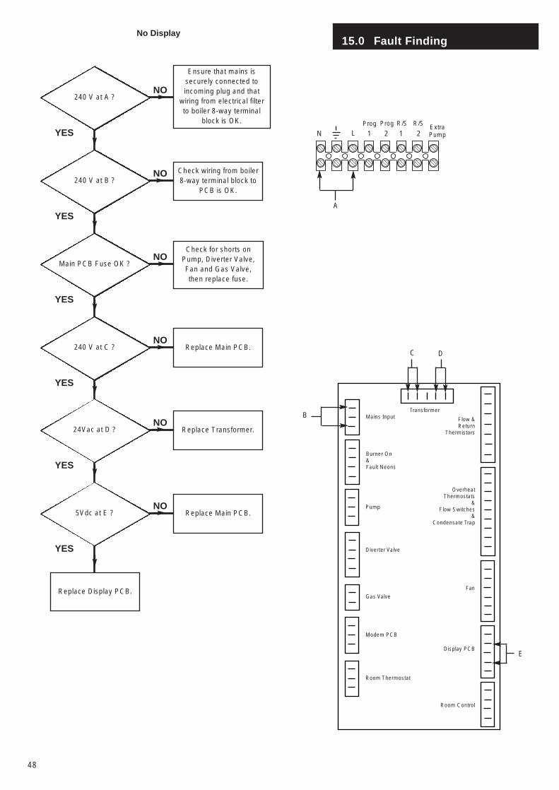
15.0 Fault Finding
48
240 V at A ?
Ensure that mains issecurely connected toincoming plug and that
wiring from electrical filterto boiler 8-way terminal
block is OK.
240 V at B ?Check wiring from boiler8-way terminal block to
PCB is OK.
Main PCB Fuse OK ?
Check for shorts onPump, Diverter Valve,Fan and Gas Valve,then replace fuse.
240 V at C ? Replace Main PCB.
24Vac at D ? Replace Transformer.
5Vdc at E ? Replace Main PCB.
YES
YES
YES
YES
YES
YES
NO
NO
NO
NO
NO
NO
Replace Display PCB.
No Display
Mains InputTransformer
Burner On&Fault Neons
Pump
Diverter Valve
Gas Valve
Modem PCB
Room Thermostat
Flow &Return
Thermistors
OverheatThermostats
&Flow Switches
&Condensate Trap
Room Control
Display PCB
Fan
A
DC
B
E
Prog
1 2 1 2LNProg R/S R/S
ExtraPump
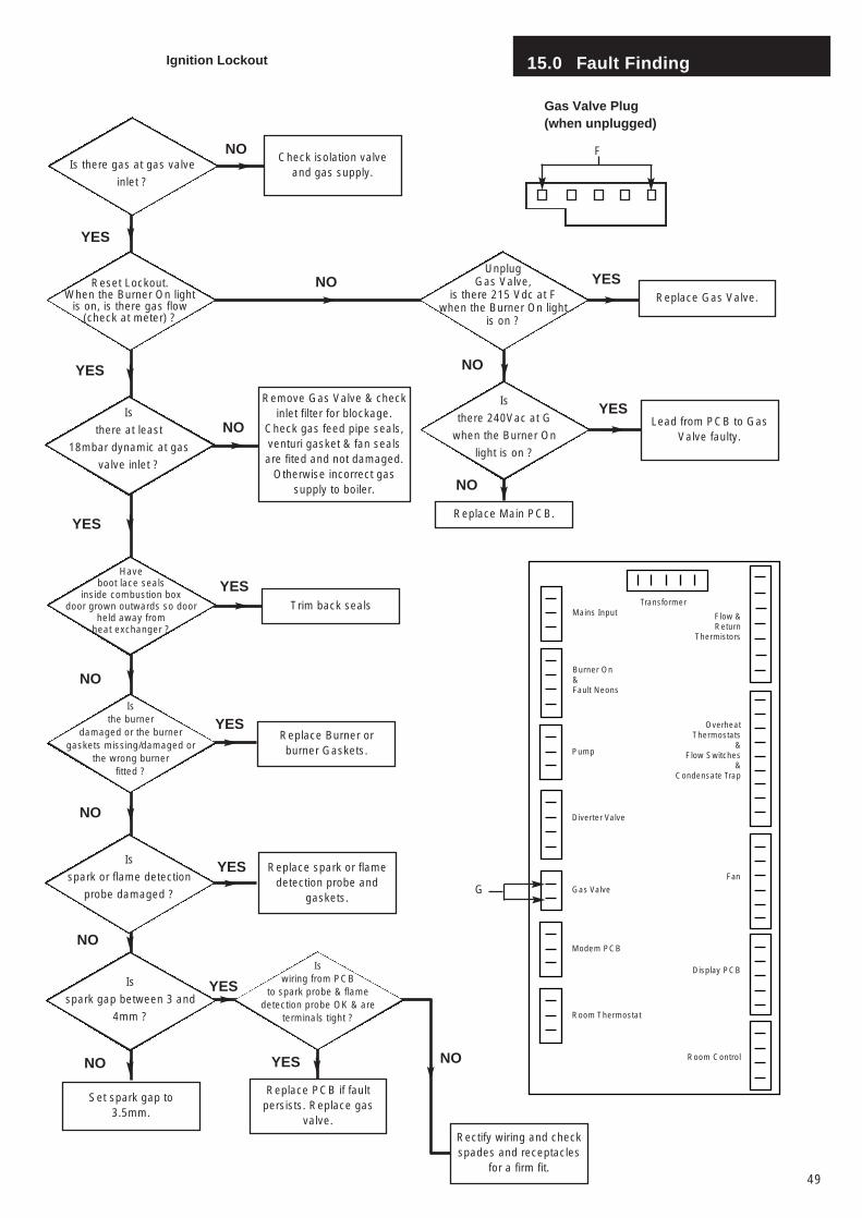
YES
15.0 Fault Finding
49
Is there gas at gas valve
inlet ?
Check isolation valveand gas supply.
YES
NO
Ignition Lockout
Reset Lockout. When the Burner On light
is on, is there gas flow(check at meter) ?
Unplug Gas Valve,
is there 215 Vdc at Fwhen the Burner On light
is on ?
Is
spark or flame detection
probe damaged ?
Have boot lace seals
inside combustion box door grown outwards so door
held away from heat exchanger ?
Is the burner
damaged or the burnergaskets missing/damaged or
the wrong burner fitted ?
Replace Main PCB.
Set spark gap to3.5mm.
Replace Gas Valve.
Trim back seals
Replace Burner orburner Gaskets.
Rectify wiring and checkspades and receptacles
for a firm fit.
Replace PCB if faultpersists. Replace gas
valve.
YES
YES
NO
NO
YES
Remove Gas Valve & checkinlet filter for blockage.
Check gas feed pipe seals,venturi gasket & fan sealsare fited and not damaged.
Otherwise incorrect gassupply to boiler.
Is
there at least
18mbar dynamic at gas
valve inlet ?
F
Gas Valve Plug(when unplugged)
Is
there 240Vac at G
when the Burner On
light is on ?
Lead from PCB to GasValve faulty.
Is
spark gap between 3 and
4mm ?
Replace spark or flamedetection probe and
gaskets.
NO
Is wiring from PCB
to spark probe & flamedetection probe OK & are
terminals tight ?
Mains InputTransformer
Burner On&Fault Neons
Pump
Diverter Valve
Gas Valve
Modem PCB
Room Thermostat
Flow &Return
Thermistors
OverheatThermostats
&Flow Switches
&Condensate Trap
Room Control
Display PCB
Fan
G
NO NO
YES
YES
NO
YES
NO
YES
YES
NO
NO
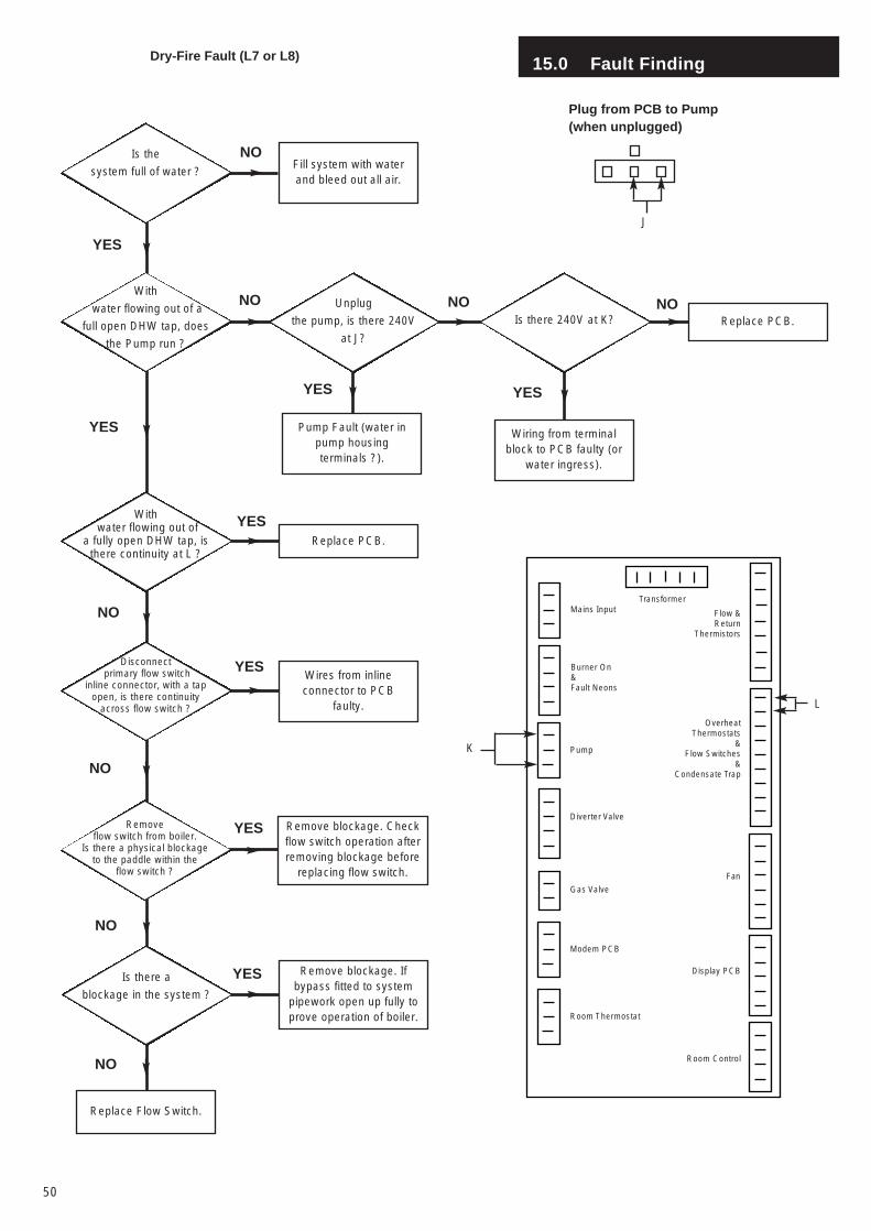
Remove blockage. Ifbypass fitted to system
pipework open up fully toprove operation of boiler.
NO
15.0 Fault Finding
50
Fill system with waterand bleed out all air.
Replace PCB.
YES
NO
Dry-Fire Fault (L7 or L8)
YES
YES
NO
NO
Is the
system full of water ?
With
water flowing out of a
full open DHW tap, does
the Pump run ?
Wires from inlineconnector to PCB
faulty.
Disconnectprimary flow switch
inline connector, with a tapopen, is there continuity
across flow switch ?
Remove blockage. Checkflow switch operation afterremoving blockage before
replacing flow switch.
Removeflow switch from boiler.
Is there a physical blockageto the paddle within the
flow switch ?
Replace Flow Switch.
NO
YES
NO
YES
Mains InputTransformer
Burner On&Fault Neons
Pump
Diverter Valve
Gas Valve
Modem PCB
Room Thermostat
Flow &Return
Thermistors
OverheatThermostats
&Flow Switches
&Condensate Trap
Room Control
Display PCB
Fan
Unplug
the pump, is there 240V
at J?
Is there 240V at K? Replace PCB.
Pump Fault (water inpump housingterminals ?).
Wiring from terminalblock to PCB faulty (or
water ingress).
Withwater flowing out of
a fully open DHW tap, isthere continuity at L ?
Is there a
blockage in the system ?
NO NO
YES YES
YES
K
L
J
Plug from PCB to Pump(when unplugged)
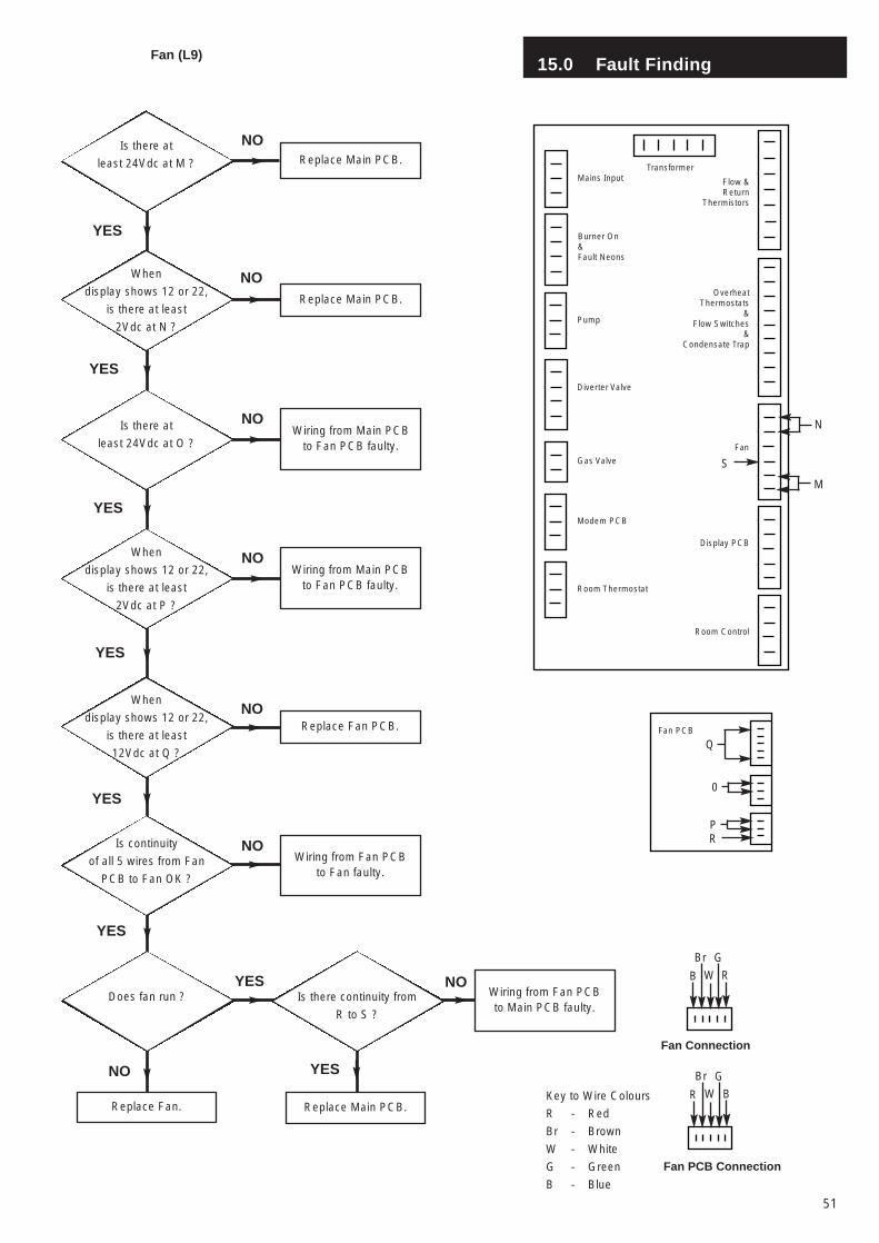
15.0 Fault Finding
51
Replace Main PCB.
Replace Main PCB.
Wiring from Main PCBto Fan PCB faulty.
YES
NO
Fan (L9)
YES
NO
NO
Is there at
least 24Vdc at M ?
Replace Fan PCB.
NO
YES
NO
YES
When
display shows 12 or 22,
is there at least
2Vdc at N ?
Is there at
least 24Vdc at O ?
Wiring from Fan PCBto Fan faulty.
NOIs continuity
of all 5 wires from Fan
PCB to Fan OK ?
Replace Fan.
NODoes fan run ?
YES
Mains InputTransformer
Burner On&Fault Neons
Pump
Diverter Valve
Gas Valve
Modem PCB
Room Thermostat
Flow &Return
Thermistors
OverheatThermostats
&Flow Switches
&Condensate Trap
Room Control
Display PCB
Fan
M
N
Fan PCB
Q
0
R
When
display shows 12 or 22,
is there at least
2Vdc at P ?
Wiring from Main PCBto Fan PCB faulty.
When
display shows 12 or 22,
is there at least
12Vdc at Q ?
Is there continuity from
R to S ?
Wiring from Fan PCBto Main PCB faulty.
Replace Main PCB.
YESNO
YES
YES
S
P
R
G
W
Br
B
B
G
W
Br
R
Fan Connection
Fan PCB Connection
Key to Wire Colours
R - Red
Br - Brown
W - White
G - Green
B - Blue
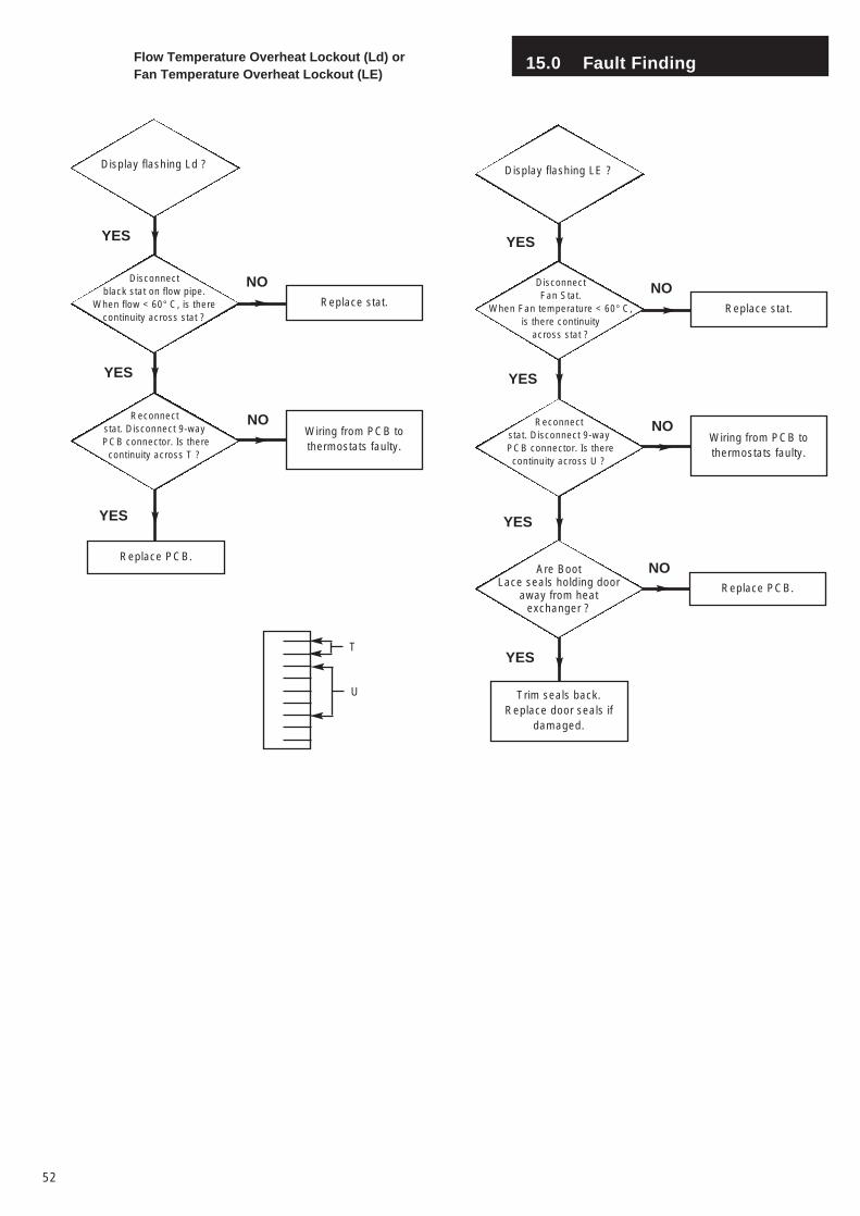
NO
15.0 Fault Finding
52
Replace stat.
Wiring from PCB tothermostats faulty.
YES
NO
YES
NO
Display flashing Ld ?
Disconnect black stat on flow pipe.
When flow < 60° C, is therecontinuity across stat ?
Flow Temperature Overheat Lockout (Ld) orFan Temperature Overheat Lockout (LE)
Replace PCB.
Reconnect stat. Disconnect 9-wayPCB connector. Is there
continuity across T ?
YES
Replace stat.
Wiring from PCB tothermostats faulty.
YES
NO
YES
NO
Display flashing LE ?
Disconnect Fan Stat.
When Fan temperature < 60° C, is there continuity
across stat ?
Replace PCB.
Reconnect stat. Disconnect 9-wayPCB connector. Is therecontinuity across U ?
YES
Are BootLace seals holding door
away from heatexchanger ?
Trim seals back.Replace door seals if
damaged.
YEST
U
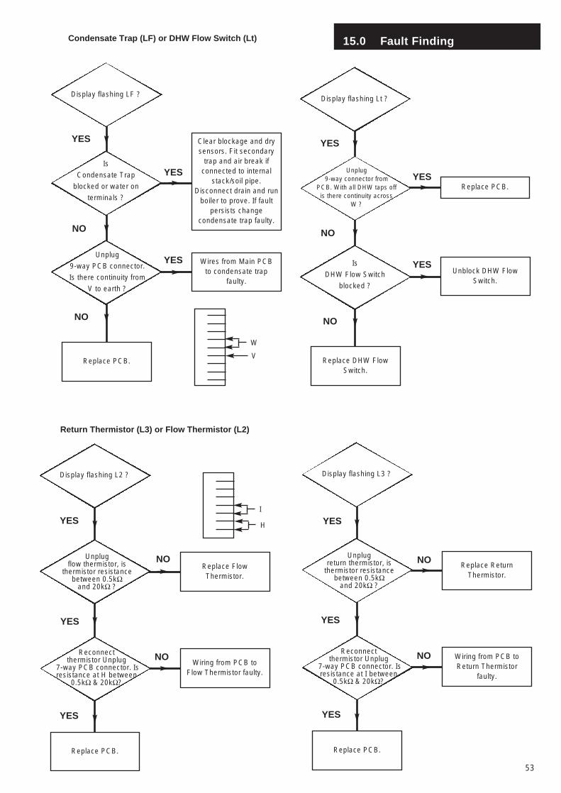
15.0 Fault Finding
53
Clear blockage and drysensors. Fit secondary
trap and air break ifconnected to internal
stack/soil pipe.Disconnect drain and run
boiler to prove. If faultpersists change
condensate trap faulty.
Wires from Main PCBto condensate trap
faulty.
YES
NO
YES
NO
Display flashing LF ?
Replace PCB.
Is
Condensate Trap
blocked or water on
terminals ?
Unplug
9-way PCB connector.
Is there continuity from
V to earth ?
YES
Condensate Trap (LF) or DHW Flow Switch (Lt)
Unblock DHW FlowSwitch.
YES
NO
YES
NO
Display flashing Lt ?
Replace DHW FlowSwitch.
Is
DHW Flow Switch
blocked ?
Unplug 9-way connector from
PCB. With all DHW taps offis there continuity across
W ?
YES
Replace PCB.
W
V
Display flashing L2 ?
Replace FlowThermistor.
Unplug flow thermistor, is
thermistor resistancebetween 0.5kΩ
and 20kΩ ?
Wiring from PCB toFlow Thermistor faulty.
NO
Return Thermistor (L3) or Flow Thermistor (L2)
Replace PCB.
YES
YES
NOReconnect thermistor Unplug
7-way PCB connector. Is resistance at H between
0.5kΩ & 20kΩ?
Display flashing L3 ?
Replace ReturnThermistor.
Unplug return thermistor, is
thermistor resistancebetween 0.5kΩ
and 20kΩ ?
Wiring from PCB toReturn Thermistor
faulty.
NO
Replace PCB.
YES
YES
NOReconnect thermistor Unplug
7-way PCB connector. Is resistance at I between
0.5kΩ & 20kΩ?
YESYES
I
H
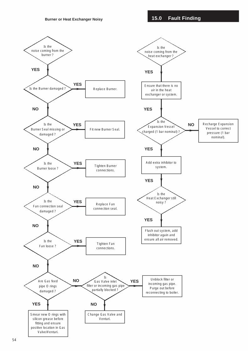
Unblock filter orincoming gas pipe.Purge out before
reconnecting to boiler.
YES
Tighten Fanconnections.
YES
Replace Fanconnection seal.
YES
Tighten Burnerconnections.
YES
Fit new Burner Seal.YES
15.0 Fault Finding
54
YES
Is thenoise coming from the
burner ?
Replace Burner.Is the Burner damaged ?
NO
YES
Burner or Heat Exchanger Noisy
Is the
Burner Seal missing or
damaged ?
Is the
Burner loose ?
Is the
Fan connection seal
damaged ?
Is the
Fan loose ?
Are Gas feed
pipe O rings
damaged ?
Is Gas Valve inlet
filter or incoming gas pipepartially blocked ?
Smear new O rings withsilicon grease before
fitting and ensurepositive location in Gas
Valve/Venturi.
Change Gas Valve andVenturi.
NO
NO
NO
NO
YES
NO
NO
Recharge ExpansionVessel to correctpressure (1 bar
nominal).
YES
YES
Is thenoise coming from the
heat exchanger ?
Ensure that there is noair in the heat
exchanger or system.
Is the Heat Exchanger still
noisy ?
NOIs the
Expansion Vessel
charged (1 bar nominal) ?
Add extra inhibitor tosystem.
Flush out system, addinhibitor again and
ensure all air removed.
YES
YES
YES
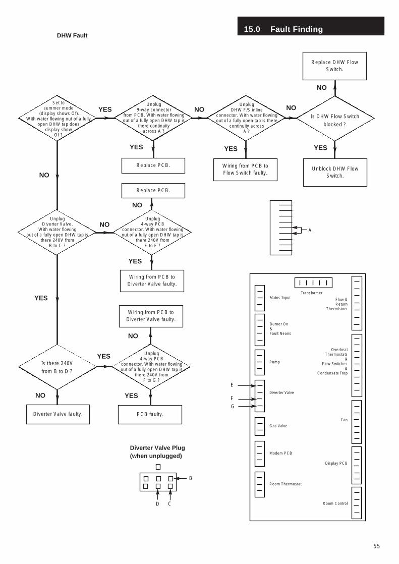
15.0 Fault Finding
55
NO
Replace PCB.
YES
NO
YES
Set tosummer mode
(display shows Of). With water flowing out of a fully
open DHW tap does display show
Of ?
Is there 240V
from B to D ?
Diverter Valve faulty.
NO
YES
DHW Fault
Mains InputTransformer
Burner On&Fault Neons
Pump
Diverter Valve
Gas Valve
Modem PCB
Room Thermostat
Flow &Return
Thermistors
OverheatThermostats
&Flow Switches
&Condensate Trap
Room Control
Display PCB
Fan
E
D
Diverter Valve Plug(when unplugged)
YES
Unplug9-way connector
from PCB. With water flowingout of a fully open DHW tap is
there continuity across A ?
UnplugDHW F/S inline
connector. With water flowingout of a fully open tap is there
continuity across A ?
Is DHW Flow Switch
blocked ?
Replace DHW FlowSwitch.
Wiring from PCB toFlow Switch faulty.
Unblock DHW FlowSwitch.
UnplugDiverter Valve.
With water flowingout of a fully open DHW tap is
there 240V from B to C ?
Unplug4-way PCB
connector. With water flowingout of a fully open DHW tap is
there 240V from E to F ?
Replace PCB.
Wiring from PCB toDiverter Valve faulty.
Unplug4-way PCB
connector. With water flowingout of a fully open DHW tap is
there 240V from F to G ?
Wiring from PCB toDiverter Valve faulty.
PCB faulty.
NO
YES
NO
NO NO
YES YES
NO
YES
F
G
B
C
A
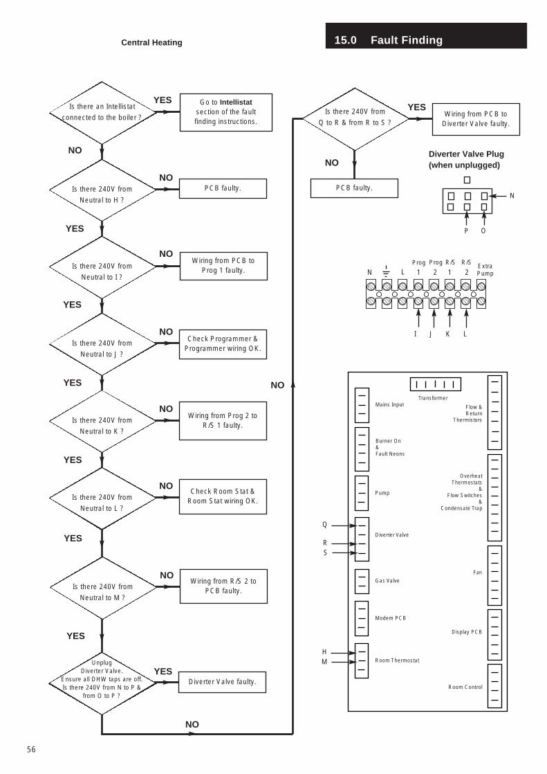
15.0 Fault Finding
56
Is there an Intellistat
connected to the boiler ?
Is there 240V from
Neutral to H ?
PCB faulty.
Is there 240V from
Neutral to I ?
Is there 240V from
Neutral to J ?
Check Programmer &Programmer wiring OK.
Is there 240V from
Neutral to K ?
Wiring from Prog 2 toR/S 1 faulty.
Is there 240V from
Neutral to L ?
Check Room Stat &Room Stat wiring OK.
YES
YES
YES
YES
YES
YES
NO
NO
NO
NO
NO
NO
Central Heating
Wiring from PCB toProg 1 faulty.
Mains InputTransformer
Burner On&Fault Neons
Pump
Diverter Valve
Gas Valve
Modem PCB
Room Thermostat
Flow &Return
Thermistors
OverheatThermostats
&Flow Switches
&Condensate Trap
Room Control
Display PCB
Fan
HM
Is there 240V from
Neutral to M ?
Wiring from R/S 2 toPCB faulty.
NO
UnplugDiverter Valve.
Ensure all DHW taps are off.Is there 240V from N to P &
from O to P ?
Diverter Valve faulty.
Is there 240V from
Q to R & from R to S ?Wiring from PCB to
Diverter Valve faulty.
NO
Go to Intellistatsection of the faultfinding instructions.
PCB faulty.
YES
NO
NO
YES
YES
RS
Q
L
Prog
1 2 1 2LNProg R/S R/S
ExtraPump
P
Diverter Valve Plug(when unplugged)
N
O
KJI
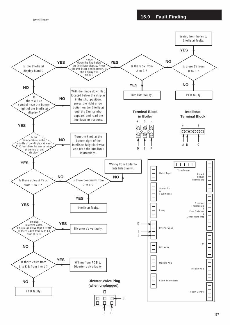
15.0 Fault Finding
57
NO
YES
Isthere a Sun
symbol near the bottom right of the Intellistat
display ?
Intellistat
Hingedown the flap below
the Intellistat display. Pressthe Intellistat Reset Button. Is
the display still blank ?
Is there 5V from
D to F ?
Wiring from boiler toIntellistat faulty.
Intellistat faulty. PCB faulty.NO
NO
YES NO
YES
Is the Intellistat
display blank ?
Is there 5V from
A to B ?
With the hinge down flaplocated below the display
in the shut position,press the right arrow
button on the Intellistatuntil the Sun symbolappears and read theIntellistat instructions.
Is thetemperature in the
middle of the display at least2° C less than the temperature
at the top of thedisplay ?
Turn the knob at thebottom right of the
Intellistat fully clockwiseand read the Intellistat
instructions.
Is there at least 4Vdc
from E to F ?
Is there continuity from
C to E ?
Wiring from boiler toIntellistat faulty.
Intellistat faulty.
UnplugDiverter Valve.
Ensure all DHW taps are off.Is there 240V from G to I &
from H to I ?
Diverter Valve faulty.
Is there 240V from
J to K & from J to L ?Wiring from PCB to
Diverter Valve faulty.
PCB faulty.
Mains InputTransformer
Burner On&Fault Neons
Pump
Diverter Valve
Gas Valve
Modem PCB
Room Thermostat
Flow &Return
Thermistors
OverheatThermostats
&Flow Switches
&Condensate Trap
Room Control
Display PCB
Fan
JL
K
I
Diverter Valve Plug(when unplugged)
G
H
+
FED
S -
Terminal Blockin Boiler
IntellistatTerminal Block
+ S-
CBA
YES
YES
NO
YES
NO NO
YES
YES
YES
NO
NO
YES
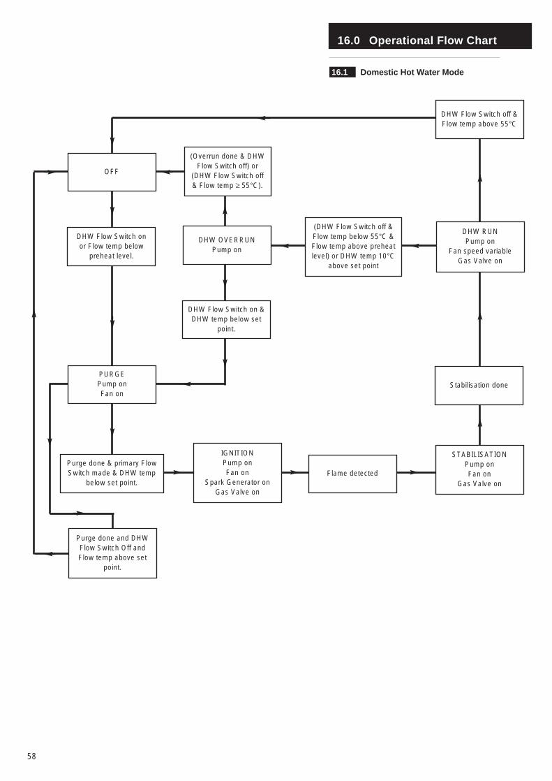
16.0 Operational Flow Chart
58
16.1 Domestic Hot Water Mode
Purge done and DHWFlow Switch Off andFlow temp above set
point.
PURGE Pump onFan on
Purge done & primary FlowSwitch made & DHW temp
below set point.
DHW Flow Switch onor Flow temp below
preheat level.
OFF
(Overrun done & DHWFlow Switch off) or
(DHW Flow Switch off& Flow temp ≥ 55°C).
DHW OVERRUNPump on
DHW Flow Switch on &DHW temp below set
point.
(DHW Flow Switch off &Flow temp below 55°C &Flow temp above preheatlevel) or DHW temp 10°C
above set point
IGNITIONPump onFan on
Spark Generator onGas Valve on
Flame detected
STABILISATIONPump onFan on
Gas Valve on
Stabilisation done
DHW RUNPump on
Fan speed variableGas Valve on
DHW Flow Switch off &Flow temp above 55°C
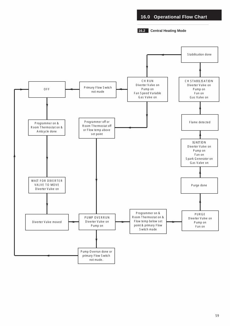
16.0 Operational Flow Chart
59
16.2 Central Heating Mode
Pump Overrun done orprimary Flow Switch
not made.
WAIT FOR DIVERTERVALVE TO MOVEDiverter Valve on
Diverter Valve moved
Programmer on &Room Thermostat on &
Anticycle done
OFF
Programmer off orRoom Thermostat offor Flow temp above
set point
CH RUNDiverter Valve on
Pump onFan Speed Variable
Gas Valve on
Programmer on &Room Thermostat on &
Flow temp below setpoint & primary Flow
Switch made
PUMP OVERRUNDiverter Valve on
Pump on
PURGEDiverter Valve on
Pump onFan on
Purge done
IGNITIONDiverter Valve on
Pump onFan on
Spark Generator onGas Valve on
Primary Flow Switchnot made
Flame detected
CH STABILISATIONDiverter Valve on
Pump onFan on
Gas Valve on
Stabilisation done

Comp No 245736 - Iss 04 - 11/03
BAXI POTTERTONA Trading Division of Baxi Heating UK LtdBrownedge Road Bamber Bridge Preston Lancashire PR5 6SNAfter Sales Service 08706 096 096 Technical Enquiries 08706 049 049Website www.baxi.co.uk