Embed Size (px)
Citation preview
DDuo-tec Combi
Installation and Service Manual
Gas Fired Wall Mounted Condensing Combination Boiler
24 - 28 - 33 - 4028 LPG
enUnited Kingdom
These instructions include the Benchmark Commissioning Checklist and should be left with theuser for safe keeping. They must be read in conjunction with the Flue Installation Guide.
2
1.0 Introduction
© Baxi Heating UK Ltd 2015
Natural Gas
Baxi Duo-tec 24 Combi ErPG.C.No 47 075 96Baxi Duo-tec 28 Combi ErPG.C.No 47 075 97Baxi Duo-tec 33 Combi ErPG.C.No 47 075 99Baxi Duo-tec 40 Combi ErPG.C.No 47 077 03
Propane
Baxi Duo-tec 28 LPG Combi ErPG.C.No 47 075 98
Building Regulations and the Benchmark CommissioningChecklist
Building Regulations (England & Wales) require notification ofthe installation of a heating appliance to the relevant LocalAuthority Building Control Department. From 1 April 2005 thiscan be achieved via a Competent Persons Self CertificationScheme as an option to notifying the Local Authority directly.Similar arrangements will follow for Scotland and will apply inNorthern Ireland from 1 January 2006.
The Health & Safety Executive operates the ‘Gas Safe Register’,a self-certification scheme for gas heating appliances.
These arrangements represent a change from the situationwhereby compliance with Building Regulations was accepted asbeing demonstrated by completion of the Benchmark Logbook(which was then left on site with the customer).
With the introduction of Self Certification Schemes, theBenchmark Logbook is being withdrawn. However, a similardocument in the form of a commissioning checklist and serviceinterval record is incorporated at the back of these instructions.
This company is a member of the Benchmark initiative and fullysupports the aims of the programme. Its aim is to improve thestandards of installation and commissioning of central heatingsystems in the UK and to encourage the regular servicing of allcentral heating systems to ensure safety and efficiency.
Building Regulations require that installations should complywith manufacturer's instructions. It is therefore important thatthe commissioning checklist is completed by the installer. Therelevant section of Building Regulations only relates todwellings. Therefore the checklist only applies if the appliance isbeing installed in a dwelling or some related structure.
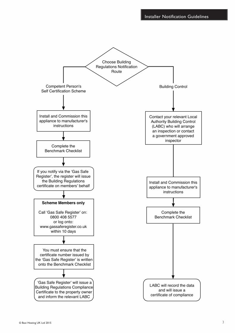
The flowchart opposite gives guidance for installers on theprocess necessary to ensure compliance with BuildingRegulations.
© Baxi Heating UK Ltd 2015 All rights reserved. No part of this publication maybe reproduced or transmitted in any form or by any means, or stored in anyretrieval system of any nature (including in any database), in each case whetherelectronic, mechanical, recording or otherwise, without the prior writtenpermission of the copyright owner, except for permitted fair dealing underCopyrights, Designs and Patents Act 1988.
Applications for the copyright owner’s permission to reproduce or make otheruse of any part of this publication should be made, giving details of the proposeduse, to the following address:
The Company Secretary, Baxi Heating UK Ltd,Brooks House, Coventry Road, Warwick. CV34 4LL
Full acknowledgement of author and source must be given.
WARNING: Any person who does any unauthorised act in relation to acopyright work may be liable to criminal prosecution and civil claims for damages.
The Benchmark Scheme
Benchmark places responsibilities on both manufacturers and installers. Thepurpose is to ensure that customers are provided with the correct equipment fortheir needs, that it is installed, commissioned and serviced in accordance with themanufacturer’s instructions by competent persons and that it meets therequirements of the appropriate Building Regulations. The Benchmark Checklistcan be used to demonstrate compliance with Building Regulations and should beprovided to the customer for future reference.
Installers are required to carry out installation, commissioning and servicing workin accordance with the Benchmark Code of Practice which is available from theHeating and Hotwater Industry Council who manage and promote the Scheme.Visit www.centralheating.co.uk for more information.
0086ISO 9001FM 00866
3
Installer Notification Guidelines
© Baxi Heating UK Ltd 2015
Choose BuildingRegulations Notification
Route
Contact your relevant LocalAuthority Building Control(LABC) who will arrangean inspection or contacta government approved
inspector
LABC will record the dataand will issue a
certificate of compliance
‘Gas Safe Register’ will issue aBuilding Regulations ComplianceCertificate to the property ownerand inform the relevant LABC
You must ensure that thecertificate number issued by
the ‘Gas Safe Register’ is written onto the Benchmark Checklist
Scheme Members only
Call ‘Gas Safe Register’ on: 0800 408 5577
or log onto:www.gassaferegister.co.uk
within 10 days
If you notify via the ‘Gas Safe Register’, the register will issue
the Building Regulationscertificate on members’ behalf
Complete theBenchmark Checklist
Install and Commission thisappliance to manufacturer's
instructions
Competent Person'sSelf Certification Scheme
Building Control
Complete theBenchmark Checklist
Install and Commission thisappliance to manufacturer's
instructions
4
Legislation
© Baxi Heating UK Ltd 2015
Codes of Practice - refer to the most recent version
This company declare that no substances harmful to healthare contained in the appliance or used during appliancemanufacture.
The appliance is suitable only for installation in GB and IE andshould be installed in accordance with the rules in force, andonly used in a suitably ventilated location.
In GB, the installation must be carried out by a Gas SafeRegistered Installer. It must be carried out in accordance withthe relevant requirements of the:• Gas Safety (Installation & Use) Regulations.• The appropriate Building Regulations either The Building
Regulations, The Building Regulations (Scotland), Building Regulations (Northern Ireland).
• The Water Fittings Regulations or Water Byelaws in Scotland.
• The Current I.E.E. Wiring Regulations.
Where no specific instructions are given, reference should bemade to the relevant British Standard Code of Practice.
In IE, the installation must be carried out by a competentPerson and installed in accordance with the current edition ofI.S. 813 ‘Domestic Gas Installations’, the current BuildingRegulations and reference should be made to the current ETCIrules for electrical installation.
All systems must be thoroughly flushed and treated withinhibitor (see section 6.2).
In GB the following Codes of Practice apply:Standard ScopeBS 6891 Gas Installation.BS 5546 Installation of hot water supplies for domestic
purposes.BS EN 12828 Heating systems in buildings.BS EN 14336 Installation & commissioning of water based
heating systems.BS 6798 Installation of gas fired hot water boilers.BS 5440 Part 1 Flues.BS 5440 Part 2 Ventilation.BS 7074 Expansion vessels and ancillary equipment for
sealed water systems.BS 7593 Treatment of water in domestic hot water
central heating systems.
In IE the following Codes of Practice apply:Standard ScopeI.S. 813 Domestic Gas Installations.The following standards give valuable additional information;BS 5546 Installation of hot water supplies for domestic
purposes.BS EN 12828 Heating systems in buildings.BS EN 14336 Installation & commissioning of water based
heating systems.BS 7074 Expansion vessels and ancillary equipment for
sealed water systems.BS 7593 Treatment of water in domestic hot water
central heating systems.
IMPORTANT - Installation, Commissioning, Service & Repair
This appliance must be installed in accordance with the manufacturer’s instructions andthe regulations in force. Read the instructions fully before installing or using theappliance.
In GB, this must be carried out by a competent person as stated in the Gas Safety(Installation & Use) Regulations.
Definition of competence: A person who works for a Gas Safe registered companyand holding current certificates in the relevant ACS modules, is deemed competent.
In IE, this must be carried out by a competent person as stated in I.S. 813 “DomesticGas Installations”.
The addition of anything that may interfere with the normal operation of the appliancewithout express written permission from the manufacturer or his agent could invalidatethe appliance warranty. In GB this could also infringe the Gas Safety (Installation andUse) Regulations.
Warning - Check the information on the data plate is compatible with local supplyconditions.
The boiler meets the requirements of Statutory Instrument “ The Boiler (Efficiency)Regulations 1993 No 3083” and is deemed to meet the requirements of Directive92/42/EEC on the energy efficiency requirements for new hot water boilers fired withliquid or gaseous fuels:-
Type test for purpose of Regulation 5 certified by: Notified Body 0085.
Product/Production certified by:Notified Bodies 0085 & 0086.
For GB/IE only.
All Gas Safe registered engineers carry an ID card with their licence number and aphotograph. You can check your engineer is registered by telephoning 0800 408 5500 or online at www.gassaferegister.co.uk
HomologationsCE Marking
EC - Declaration of ConformityBaxi Heating UK Limited being the manufacturer / distributor within the EuropeanEconomic Area of the following
Baxi Duo-tec 24 - 28 - 33 - 40 Combi ErPBaxi Duo-tec 28 LPG Combi ErP
declare that the above is in conformity with the provisions of the Council Directive
2009/142/EC 92/42/EEC 2004/108/EC 2006/95/EC2009/125/EC 2010/30/EU
and has been subject to the following conformity procedures laid down in
Annex 2 - Article 3 of 2009/142/EC
under the supervision of the British Standards Institution, a Notified Body authorizedby the United Kingdom Competent Authority, and carrying the Notified BodyNumber 0086.
Type test for purpose of Regulation 5 certified by: Notified Body 0085.
Product/Production certified by:Notified Body 0085 & 0086.
For GB/IE only.
5
Safe Manual Handling
© Baxi Heating UK Ltd 2015
General
The following advice should be adhered to, from when first handling the boiler to the final stages of installation, and also during maintenance.
Most injuries as a result of inappropriate handling and lifting are to the back, but all other parts of the body are vulnerable, particularly shoulders, arms and hands.Health & Safety is the responsibility of EVERYONE.
There is no ‘safe’ limit for one man - each person has different capabilities. The boiler should be handled and lifted by TWO PEOPLE.
Do not handle or lift unless you feel physically able.
Wear appropriate Personal Protection Equipment e.g. protective gloves, safety footwear etc.
Preparation
Co-ordinate movements - know where, and when, you are both going.
Minimise the number of times needed to move the boiler - plan ahead.
Always ensure when handling or lifting the route is clear and unobstructed. If possible avoid steps, wet or slippery surfaces, unlit areas etc. and take special careon ladders/into lofts.
Technique
When handling or lifting always use safe techniques - keep your back straight, bend your knees. Don’t twist - move your feet, avoid bending forwards andsideways and keep the load as close to your body as possible.
Where possible transport the boiler using a sack truck or other suitable trolley.
Always grip the boiler firmly, and before lifting feel where the weight is concentrated to establish the centre of gravity, repositioning yourself as necessary. See the‘Installation’ section of these instructions for recommended lift points.
Remember
The circumstances of each installation are different. Always assess the risks associated with handling and lifting according to the individual conditions.
If at any time when installing the boiler you feel that you may have injured yourself STOP !! DO NOT ‘work through’ the pain - you may cause further injury.
IF IN ANY DOUBT DO NOT HANDLE OR LIFT THE BOILER - OBTAIN ADVICE OR ASSISTANCE BEFORE PROCEEDING !!
6 © Baxi Heating UK Ltd 2015
CONTENTS
1.0 Introduction 7
2.0 General Layout 8
3.0 Appliance Operation 9
4.0 Technical Data 10
5.0 Dimensions and Fixings 11
6.0 System Details 12
7.0 Site Requirements 15
8.0 Flue Options 21
9.0 Installation 23
10.0 Commissioning 28
11.0 Completion 31
12.0 Servicing 32
13.0 Changing Components 34
14.0 Setting the Gas Valve 43
15.0 Electrical 44
16.0 Short Parts List 45
17.0 Fault Finding 46
18.0 LPG Model Supplement 52
19.0 Notes 52
Benchmark Checklist 58
Section Page
7
1.0 Introduction
© Baxi Heating UK Ltd 2015
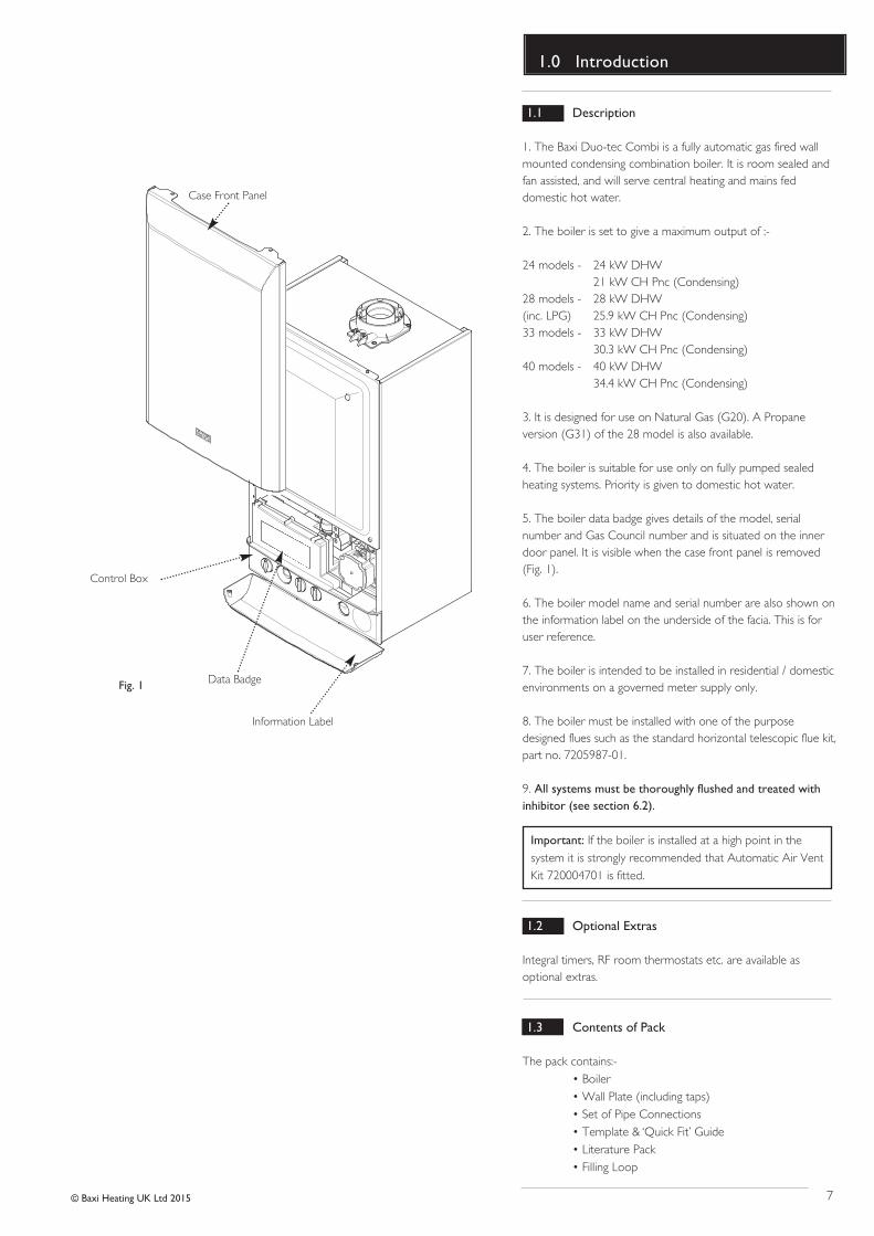
1.1 Description
1. The Baxi Duo-tec Combi is a fully automatic gas fired wallmounted condensing combination boiler. It is room sealed andfan assisted, and will serve central heating and mains feddomestic hot water.
2. The boiler is set to give a maximum output of :-
24 models - 24 kW DHW21 kW CH Pnc (Condensing)
28 models - 28 kW DHW(inc. LPG) 25.9 kW CH Pnc (Condensing)33 models - 33 kW DHW
30.3 kW CH Pnc (Condensing)40 models - 40 kW DHW
34.4 kW CH Pnc (Condensing)
3. It is designed for use on Natural Gas (G20). A Propaneversion (G31) of the 28 model is also available.
4. The boiler is suitable for use only on fully pumped sealedheating systems. Priority is given to domestic hot water.
5. The boiler data badge gives details of the model, serialnumber and Gas Council number and is situated on the innerdoor panel. It is visible when the case front panel is removed(Fig. 1).
6. The boiler model name and serial number are also shown onthe information label on the underside of the facia. This is foruser reference.
7. The boiler is intended to be installed in residential / domesticenvironments on a governed meter supply only.
8. The boiler must be installed with one of the purposedesigned flues such as the standard horizontal telescopic flue kit,part no. 7205987-01 .
9. All systems must be thoroughly flushed and treated withinhibitor (see section 6.2).
Important: If the boiler is installed at a high point in thesystem it is strongly recommended that Automatic Air VentKit 720004701 is fitted.
1.2 Optional Extras
Integral timers, RF room thermostats etc. are available asoptional extras.
1.3 Contents of Pack
The pack contains:-• Boiler• Wall Plate (including taps)• Set of Pipe Connections• Template & ‘Quick Fit’ Guide• Literature Pack• Filling Loop
Fig. 1
Control Box
Case Front Panel
Data Badge
Information Label
8
2.0 General Layout
© Baxi Heating UK Ltd 2015
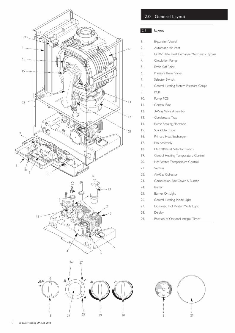
2.1 Layout
1. Expansion Vessel
2. Automatic Air Vent
3. DHW Plate Heat Exchanger/Automatic Bypass
4. Circulation Pump
5. Drain Off Point
6. Pressure Relief Valve
7. Selector Switch
8. Central Heating System Pressure Gauge
9. PCB
10. Pump PCB
11. Control Box
12. 3-Way Valve Assembly
13. Condensate Trap
14. Flame Sensing Electrode
15. Spark Electrode
16. Primary Heat Exchanger
17. Fan Assembly
18. On/Off/Reset Selector Switch
19. Central Heating Temperature Control
20. Hot Water Temperature Control
21. Venturi
22. Air/Gas Collector
23. Combustion Box Cover & Burner
24. Igniter
25. Burner On Light
26. Central Heating Mode Light
27. Domestic Hot Water Mode Light
28. Display
29. Position of Optional Integral Timer
1
18 19 20 8
bar
0
1
2
3
4
23
2
3
45
6
7
89
11
12
13
14
15
16
17
21
22
24
25
26 27
28 29
10
9
3.0 Appliance Operation
© Baxi Heating UK Ltd 2015
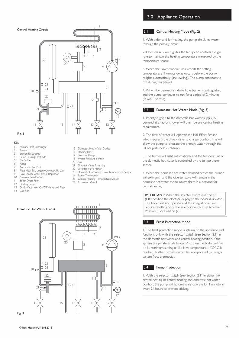
3.1 Central Heating Mode (Fig. 2)
1. With a demand for heating, the pump circulates waterthrough the primary circuit.
2. Once main burner ignites the fan speed controls the gasrate to maintain the heating temperature measured by thetemperature sensor.
3. When the flow temperature exceeds the settingtemperature, a 3 minute delay occurs before the burnerrelights automatically (anti-cycling). The pump continues torun during this period.
4. When the demand is satisfied the burner is extinguishedand the pump continues to run for a period of 3 minutes(Pump Overrun).
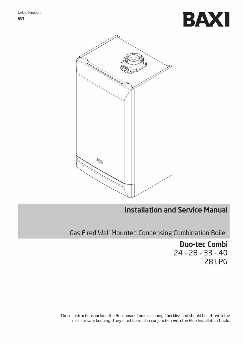
3.2 Domestic Hot Water Mode (Fig. 3)
1. Priority is given to the domestic hot water supply. Ademand at a tap or shower will override any central heatingrequirement.
2. The flow of water will operate the Hall Effect Sensorwhich requests the 3 way valve to change position. This willallow the pump to circulate the primary water through theDHW plate heat exchanger.
3. The burner will light automatically and the temperature ofthe domestic hot water is controlled by the temperaturesensor.
4. When the domestic hot water demand ceases the burnerwill extinguish and the diverter valve will remain in thedomestic hot water mode, unless there is a demand forcentral heating.
IMPORTANT: When the selector switch is in the ‘0’(Off) position the electrical supply to the boiler is isolated.The boiler will not operate and the integral timer willrequire resetting once the selector switch is set to eitherPosition (i) or Position (ii).
3.3 Frost Protection Mode
1. The frost protection mode is integral to the appliance andfunctions only with the selector switch (see Section 2.1) inthe domestic hot water and central heating position. If thesystem temperature falls below 5° C then the boiler will fireon its minimum setting until a flow temperature of 30° C isreached. Further protection can be incorporated by using asystem frost thermostat.
3.4 Pump Protection
1. With the selector switch (see Section 2.1) in either thecentral heating or central heating and domestic hot waterposition, the pump will automatically operate for 1 minute inevery 24 hours to prevent sticking.
Fig. 3
1
2
4
5 6
7
8
9
10
11
1213141516
17
18
21
22
24
25
263
1 Primary Heat Exchanger2 Burner 3 Ignition Electrodes4 Flame Sensing Electrode5 Gas Valve6 Pump7 Automatic Air Vent8 Plate Heat Exchanger/Automatic By-pass9 Flow Sensor with Filter & Regulator10 Pressure Relief Valve11 Boiler Drain Point12 Heating Return13 Cold Water Inlet On/Off Valve and Filter14 Gas Inlet
15 Domestic Hot Water Outlet16 Heating Flow17 Pressure Gauge18 Water Pressure Sensor20 Fan21 Diverter Valve Assembly22 Diverter Valve Motor23 Domestic Hot Water Flow Temperature Sensor24 Safety Thermostat25 Central Heating Temperature Sensor26 Expansion Vessel
Key
Central Heating Circuit
Domestic Hot Water Circuit1
2
4
5 6
7
8
9
10
11
1213141516
17
18
21
22
2425
263
Fig. 2
23
23
20
20
10
4.0 Technical Data
© Baxi Heating UK Ltd 2015
0200 400 600 800 1000 1200
0.5
1
1.5
2
2.5
3
3.5
4
Met
re (
wg)
Flow Rate (l/h)
Pump - Available Head
0
5
5.5
4.5
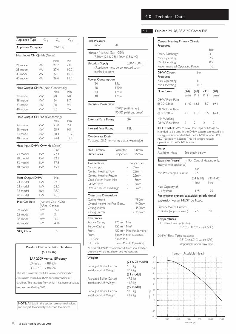
4.1 Duo-tec 24, 28, 33 & 40 Combi ErP
Flue Terminal Diameter 100mmDimensions Projection 125mm
Outercase DimensionsCasing Height - 780mmOverall Height Inc Flue Elbow - 940mmCasing Width - 450mmCasing Depth - 345mm
Central Heating Primary CircuitPressures
barSafety Discharge 3Max Operating 2.5Min Operating 0.5Recommended Operating Range 1-2
DHW Circuit barPressuresMax Operating 8Min Operating 0.15
Flow Rates (24) (28) (33) (40)l/min l/min l/min l/min
DHW Flow Rate @ 30o C Rise 11.43 13.3 15.7 19.1
DHW Flow Rate@ 35o C Rise 9.8 11.5 13.5 16.4
Min WorkingDHW Flow Rate 2 2 2 2
PumpAvailable Head See graph below
Expansion Vessel - (For Central Heating only.Integral with appliance)
barMin Pre-charge Pressure 0.5
(24 & 28) (33 & 40)litre litre
Max Capacity of CH System 125 125
For greater system capacities an additionalexpansion vessel MUST be fitted.
Primary Water Contentof Boiler (unpressurised) 2.5 2.8
Connections copper tailsGas Supply - 22mmCentral Heating Flow - 22mmCentral Heating Return - 22mmCold Water Mains Inlet - 15mmDHW Flow - 15mmPressure Relief Discharge - 15mm
TemperaturesC.H. Flow Temp (adjustable)
25°C to 80°C max (± 5°C)
D.H.W. Flow Temp (adjustable)
35°C to 60°C max (± 5°C)dependent upon flow rate
Heat Output CH Pn (Non-Condensing)Max Min
24 model kW 20 6.828 model kW 24 8.733 model kW 28 9.440 model kW 32 9.6
Electrical Supply 230V~ 50Hz (Appliance must be connected to an earthed supply)
Electrical Protection IPX0D (with timer)IPX5D (without timer)
Internal Fuse Rating F2L
Appliance Category CAT I 2H
Inlet Pressurembar 20
Injector (Natural Gas - G20)7.5mm (24 & 28) 12mm (33 & 40)
Appliance Type C13 C33 C53
Heat Output CH Pnc (Condensing)Max Min
24 model kW 21.0 7.428 model kW 25.9 9.533 model kW 30.3 10.240 model kW 34.4 12.1
Heat Output DHW Max24 model kW 24.028 model kW 28.033 model kW 33.040 model kW 40.0
Max Gas Rate (Natural Gas - G20)(After 10 mins)
24 model m3/h 2.6128 model m3/h 3.133 model m3/h 3.640 model m3/h 4.36
Condensate DrainTo accept 21.5mm (3/4 in) plastic waste pipe
Heat Input CH Qn Hs (Gross)
Max Min24 model kW 22.7 7.828 model kW 27.4 10.033 model kW 32.1 10.840 model kW 36.4 11.0
Heat Input DHW Qnw Hs (Gross)Max
24 model kW 27.428 model kW 32.133 model kW 37.840 model kW 45.7
External Fuse Rating 3A
ClearancesAbove Casing 175 mm MinBelow Casing 150 mm Min*Front 450 mm Min (For Servicing)
Front 5 mm Min (In Operation)
L.H. Side 5 mm MinR.H. Side 5 mm Min (In Operation)
*This is MINIMUM recommended dimension. Greaterclearance will aid installation and maintenance.
IMPORTANT: Where Low Flow Taps or Fittings areintended to be used in the DHW system connected it isstrongly recommended that the DHW flow rate DOESNOT fall below 2.5l/min. This will ensure reliableoperation of the DHW function.
NOTE: All data in this section are nominal values and subject to normal production tolerances.
NOx Class 5
SAP 2009 Annual Efficiency24 & 28 - 88.6%33 & 40 - 88.5%
This value is used in the UK Government’s Standard
Assessment Procedure (SAP) for energy rating of
dwellings. The test data from which it has been calculated
has been certified by 0085.
Product Characteristics Database(SEDBUK)
Power Consumption 24 85w28 120w33 125w40 125w
Weights(24 & 28 model)
Packaged Boiler Carton 46.0 kgInstallation Lift Weight 40.2 kg
(33 model)Packaged Boiler Carton 47.5 kgInstallation Lift Weight 41.7 kg
(40 model)Packaged Boiler Carton 48.0 kgInstallation Lift Weight 42.2 kg
11© Baxi Heating UK Ltd 2015
4.0 Technical Data
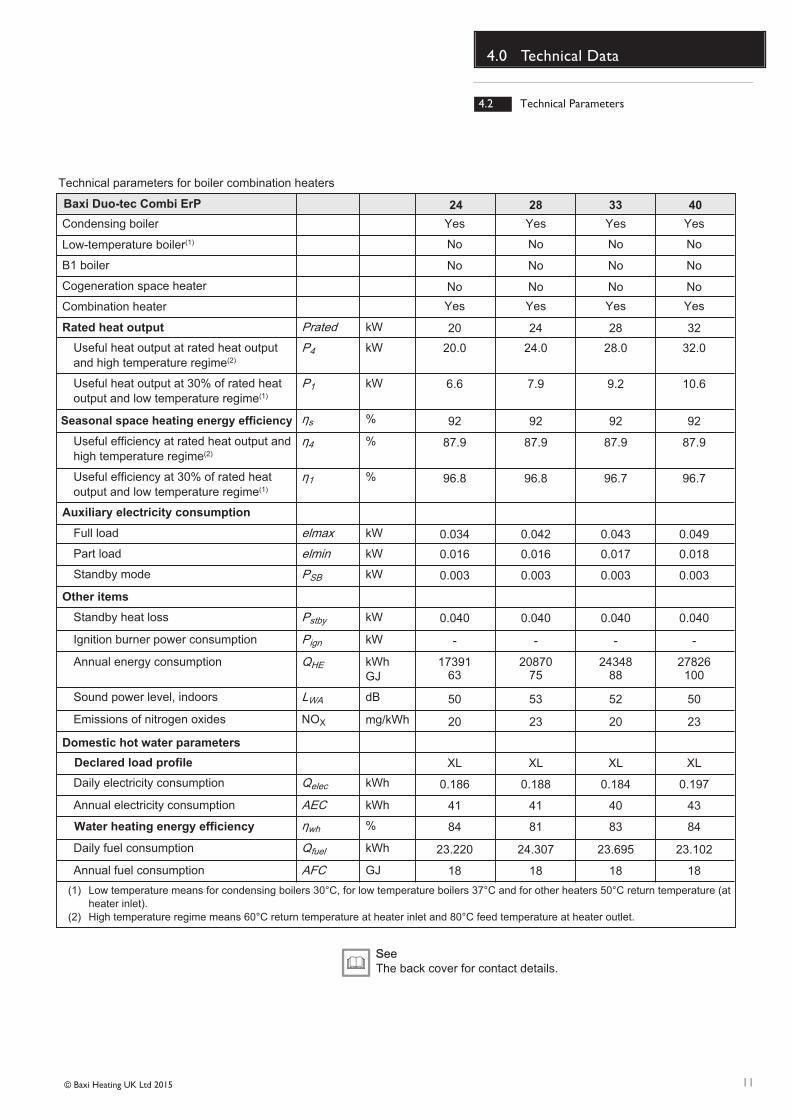
4.2 Technical Parameters
Technical parameters for boiler combination heaters
Condensing boiler Yes
24Baxi Duo-tec Combi ErP
Rated heat output
Seasonal space heating energy efficiency
Auxiliary electricity consumption
Other items
28 33 40
YesYes Yes
Low-temperature boiler(1) No NoNo No
B1 boiler
Cogeneration space heater
Combination heater
Prated kW
Useful heat output at rated heat output and high temperature regime(2)
P4 kW
Useful heat output at 30% of rated heat output and low temperature regime(1)
P1 kW
s %
Useful efficiency at rated heat output and high temperature regime(2)
4 %
Useful efficiency at 30% of rated heat output and low temperature regime(1)
1 %
Full load elmax kW
Part load elmin kW
Standby mode PSB kW
Standby heat loss Pstby kW
Ignition burner power consumption Pign kW
Annual energy consumption QHE kWhGJ
Sound power level, indoors LWA dB
Emissions of nitrogen oxides NOX
Daily electricity consumption
Domestic hot water parameters
Declared load profile
Water heating energy efficiency
Qelec kWh
Annual electricity consumption AEC kWh
wh %
Daily fuel consumption Qfuel kWh
Annual fuel consumption AFC GJ
(1) Low temperature means for condensing boilers 30°C, for low temperature boilers 37°C and for other heaters 50°C return temperature (at heater inlet).
(2) High temperature regime means 60°C return temperature at heater inlet and 80°C feed temperature at heater outlet.
SSeeThe back cover for contact details.
Yes YesYes Yes
No NoNo No
No NoNo No
20 2824 32
20.0 28.024.0 32.0
6.6 9.27.9 10.6
92 9292 92
87.9 87.987.9 87.9
96.8 96.796.8 96.7
0.034 0.0430.042 0.049
0.016 0.0170.016 0.018
0.003 0.0030.003 0.003
0.040 0.0400.040 0.040
- -- -
17391 2434820870 2782663 8875 100
50 5253 50
20 2023 23
XL XLXL XL
0.186 0.1840.188 0.197
41 4041 43
84 8381 84
23.220 23.69524.307 23.102
18 1818 18
mg/kWh
12
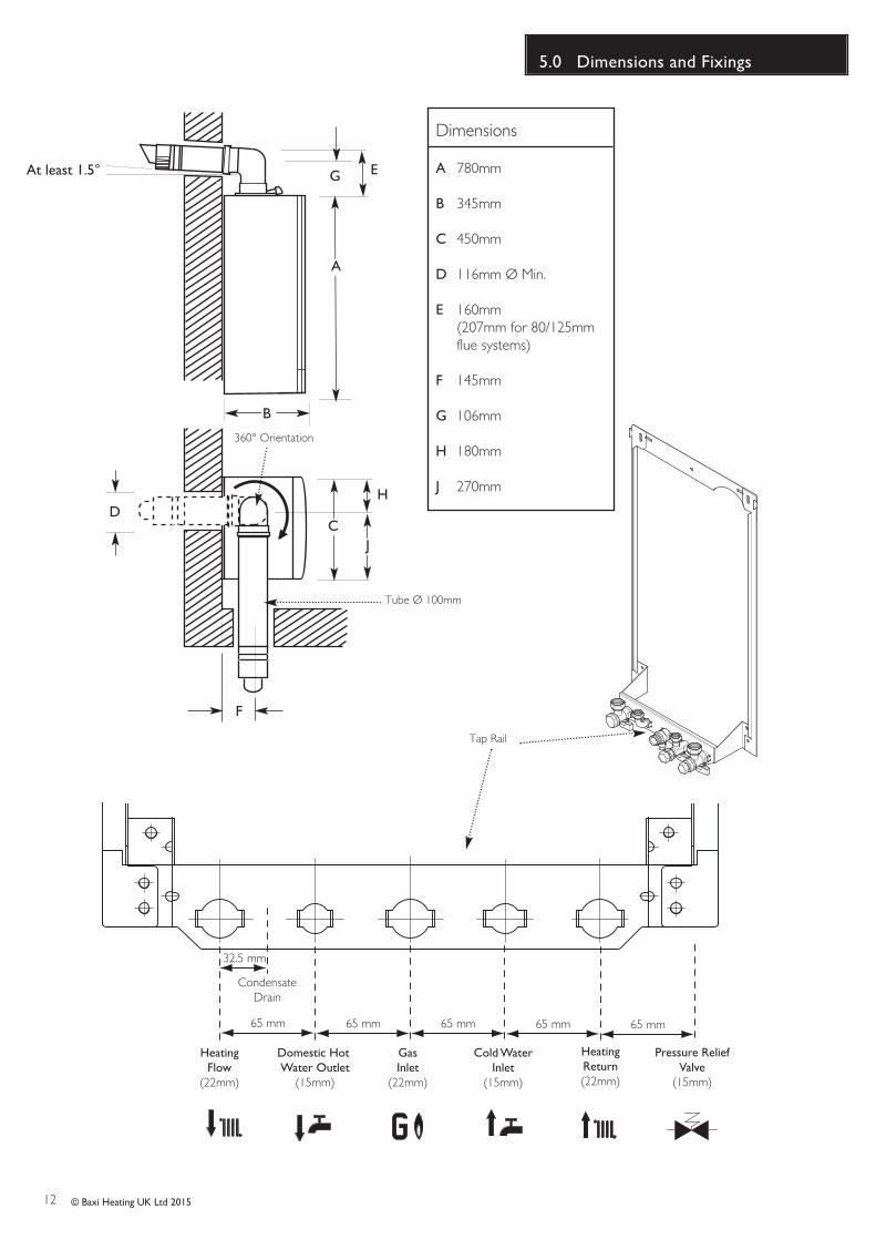
5.0 Dimensions and Fixings
© Baxi Heating UK Ltd 2015
Dimensions
A 780mm
B 345mm
C 450mm
D 116mm Ø Min.
E 160mm(207mm for 80/125mm flue systems)
F 145mm
G 106mm
H 180mm
J 270mm
Domestic Hot Water Outlet(15mm)
Cold WaterInlet(15mm)
HeatingReturn(22mm)
HeatingFlow(22mm)
Pressure ReliefValve(15mm)
GasInlet(22mm)
65 mm 65 mm 65 mm 65 mm 65 mm
32.5 mm
CondensateDrain
Tap Rail
360° Orientation
Tube Ø 100mm
DC
B
A
EG
F
At least 1.5°
H
J
13
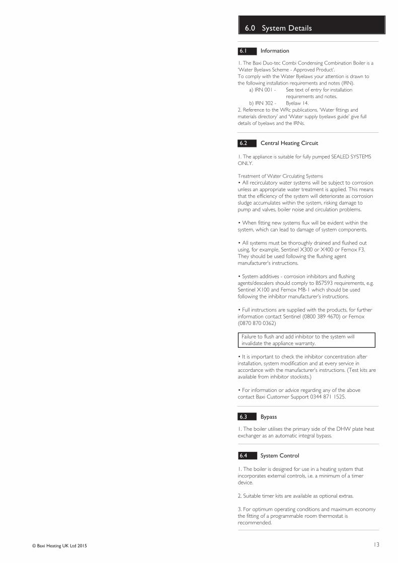
6.0 System Details
© Baxi Heating UK Ltd 2015
6.1 Information
1. The Baxi Duo-tec Combi Condensing Combination Boiler is a‘Water Byelaws Scheme - Approved Product’.To comply with the Water Byelaws your attention is drawn tothe following installation requirements and notes (IRN).
a) IRN 001 - See text of entry for installation requirements and notes.
b) IRN 302 - Byelaw 14.2. Reference to the WRc publications, ‘Water fittings andmaterials directory’ and ‘Water supply byelaws guide’ give fulldetails of byelaws and the IRNs.
6.2 Central Heating Circuit
1. The appliance is suitable for fully pumped SEALED SYSTEMSONLY.
Treatment of Water Circulating Systems• All recirculatory water systems will be subject to corrosionunless an appropriate water treatment is applied. This meansthat the efficiency of the system will deteriorate as corrosionsludge accumulates within the system, risking damage topump and valves, boiler noise and circulation problems.
• When fitting new systems flux will be evident within thesystem, which can lead to damage of system components.
• All systems must be thoroughly drained and flushed outusing, for example, Sentinel X300 or X400 or Fernox F3.They should be used following the flushing agentmanufacturer’s instructions.
• System additives - corrosion inhibitors and flushing agents/descalers should comply to BS7593 requirements, e.g.Sentinel X100 and Fernox MB-1 which should be usedfollowing the inhibitor manufacturer’s instructions.
• Full instructions are supplied with the products, for furtherinformation contact Sentinel (0800 389 4670) or Fernox(0870 870 0362)
Failure to flush and add inhibitor to the system willinvalidate the appliance warranty.
• It is important to check the inhibitor concentration afterinstallation, system modification and at every service inaccordance with the manufacturer’s instructions. (Test kits areavailable from inhibitor stockists.)
• For information or advice regarding any of the abovecontact Baxi Customer Support 0344 871 1525.
6.3 Bypass
1. The boiler utilises the primary side of the DHW plate heatexchanger as an automatic integral bypass.
6.4 System Control
1. The boiler is designed for use in a heating system thatincorporates external controls, i.e. a minimum of a timerdevice.
2. Suitable timer kits are available as optional extras.
3. For optimum operating conditions and maximum economythe fitting of a programmable room thermostat isrecommended.
14
6.0 System Details
© Baxi Heating UK Ltd 2015
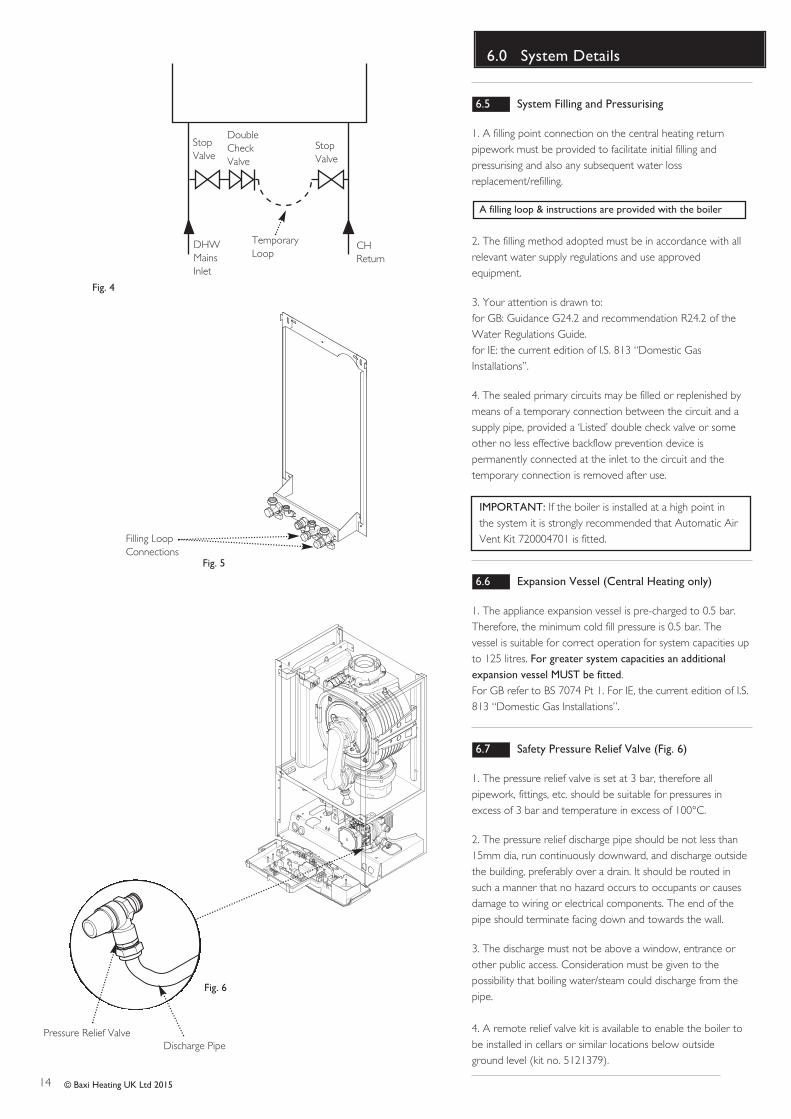
6.5 System Filling and Pressurising
1. A filling point connection on the central heating returnpipework must be provided to facilitate initial filling andpressurising and also any subsequent water lossreplacement/refilling.
A filling loop & instructions are provided with the boiler
2. The filling method adopted must be in accordance with allrelevant water supply regulations and use approvedequipment.
3. Your attention is drawn to: for GB: Guidance G24.2 and recommendation R24.2 of theWater Regulations Guide. for IE: the current edition of I.S. 813 “Domestic GasInstallations”.
4. The sealed primary circuits may be filled or replenished bymeans of a temporary connection between the circuit and asupply pipe, provided a ‘Listed’ double check valve or someother no less effective backflow prevention device ispermanently connected at the inlet to the circuit and thetemporary connection is removed after use.
IMPORTANT: If the boiler is installed at a high point inthe system it is strongly recommended that Automatic AirVent Kit 720004701 is fitted.
6.6 Expansion Vessel (Central Heating only)
1. The appliance expansion vessel is pre-charged to 0.5 bar.Therefore, the minimum cold fill pressure is 0.5 bar. Thevessel is suitable for correct operation for system capacities upto 125 litres. For greater system capacities an additionalexpansion vessel MUST be fitted. For GB refer to BS 7074 Pt 1. For IE, the current edition of I.S.813 “Domestic Gas Installations”.
6.7 Safety Pressure Relief Valve (Fig. 6)
1. The pressure relief valve is set at 3 bar, therefore allpipework, fittings, etc. should be suitable for pressures inexcess of 3 bar and temperature in excess of 100°C.
2. The pressure relief discharge pipe should be not less than15mm dia, run continuously downward, and discharge outsidethe building, preferably over a drain. It should be routed insuch a manner that no hazard occurs to occupants or causesdamage to wiring or electrical components. The end of thepipe should terminate facing down and towards the wall.
3. The discharge must not be above a window, entrance orother public access. Consideration must be given to thepossibility that boiling water/steam could discharge from thepipe.
4. A remote relief valve kit is available to enable the boiler tobe installed in cellars or similar locations below outsideground level (kit no. 5121379).
Fig. 4
Fig. 6
StopValve
DoubleCheckValve
DHWMainsInlet
CHReturn
TemporaryLoop
Pressure Relief ValveDischarge Pipe
StopValve
Filling LoopConnections
Fig. 5
15
6.0 System Details
© Baxi Heating UK Ltd 2015
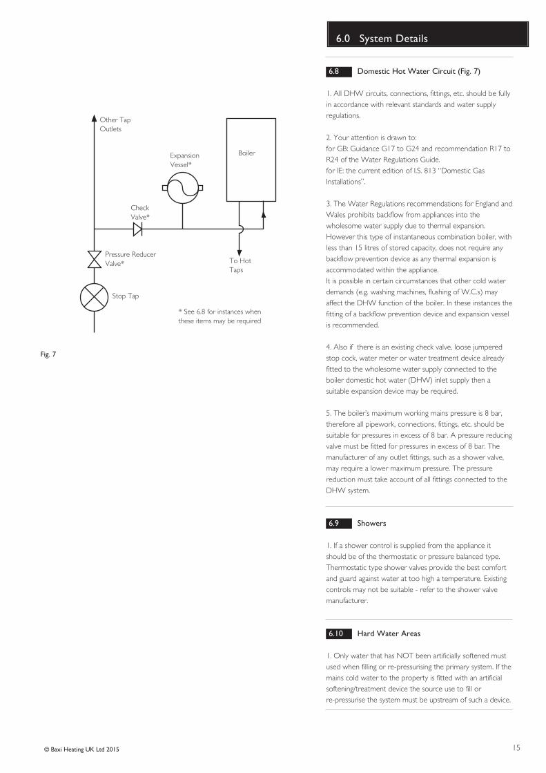
Boiler
Other TapOutlets
ExpansionVessel*
To HotTaps
CheckValve*
Pressure ReducerValve*
Stop Tap
Fig. 7
6.8 Domestic Hot Water Circuit (Fig. 7)
1. All DHW circuits, connections, fittings, etc. should be fullyin accordance with relevant standards and water supplyregulations.
2. Your attention is drawn to: for GB: Guidance G17 to G24 and recommendation R17 toR24 of the Water Regulations Guide.for IE: the current edition of I.S. 813 “Domestic GasInstallations”.
3. The Water Regulations recommendations for England andWales prohibits backflow from appliances into thewholesome water supply due to thermal expansion.However this type of instantaneous combination boiler, withless than 15 litres of stored capacity, does not require anybackflow prevention device as any thermal expansion isaccommodated within the appliance. It is possible in certain circumstances that other cold waterdemands (e.g. washing machines, flushing of W.C.s) mayaffect the DHW function of the boiler. In these instances thefitting of a backflow prevention device and expansion vesselis recommended.
4. Also if there is an existing check valve, loose jumperedstop cock, water meter or water treatment device alreadyfitted to the wholesome water supply connected to theboiler domestic hot water (DHW) inlet supply then asuitable expansion device may be required.
5. The boiler’s maximum working mains pressure is 8 bar,therefore all pipework, connections, fittings, etc. should besuitable for pressures in excess of 8 bar. A pressure reducingvalve must be fitted for pressures in excess of 8 bar. Themanufacturer of any outlet fittings, such as a shower valve,may require a lower maximum pressure. The pressurereduction must take account of all fittings connected to theDHW system.
6.9 Showers
1. If a shower control is supplied from the appliance itshould be of the thermostatic or pressure balanced type.Thermostatic type shower valves provide the best comfortand guard against water at too high a temperature. Existingcontrols may not be suitable - refer to the shower valvemanufacturer.
6.10 Hard Water Areas
1. Only water that has NOT been artificially softened mustused when filling or re-pressurising the primary system. If themains cold water to the property is fitted with an artificialsoftening/treatment device the source use to fill or re-pressurise the system must be upstream of such a device.
* See 6.8 for instances whenthese items may be required
16
7.0 Site Requirements
© Baxi Heating UK Ltd 2015
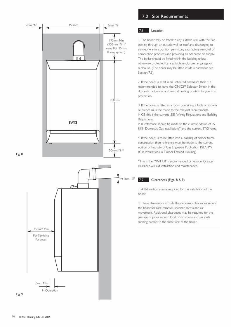
7.1 Location
1. The boiler may be fitted to any suitable wall with the fluepassing through an outside wall or roof and discharging toatmosphere in a position permitting satisfactory removal ofcombustion products and providing an adequate air supply.The boiler should be fitted within the building unlessotherwise protected by a suitable enclosure i.e. garage orouthouse. (The boiler may be fitted inside a cupboard-seeSection 7.3).
2. If the boiler is sited in an unheated enclosure then it isrecommended to leave the ON/OFF Selector Switch in thedomestic hot water and central heating position to give frostprotection.
3. If the boiler is fitted in a room containing a bath or showerreference must be made to the relevant requirements.In GB this is the current I.E.E. Wiring Regulations and BuildingRegulations.In IE reference should be made to the current edition of I.S.813 “Domestic Gas Installations” and the current ETCI rules.
4. If the boiler is to be fitted into a building of timber frameconstruction then reference must be made to the currentedition of Institute of Gas Engineers Publication IGE/UP/7(Gas Installations in Timber Framed Housing).
*This is the MINIMUM recommended dimension. Greaterclearance will aid installation and maintenance.
7.2 Clearances (Figs. 8 & 9)
1. A flat vertical area is required for the installation of theboiler.
2. These dimensions include the necessary clearances aroundthe boiler for case removal, spanner access and airmovement. Additional clearances may be required for thepassage of pipes around local obstructions such as joistsrunning parallel to the front face of the boiler.
150mm Min*
780mm
450mm
175mm Min(300mm Min if
using 80/125mmflueing system)
5mm Min
5mm Min
450mm Min
For ServicingPurposes
Fig. 8
Fig. 9In Operation
5mm Min
At least 1.5°
17
7.0 Site Requirement
© Baxi Heating UK Ltd 2015
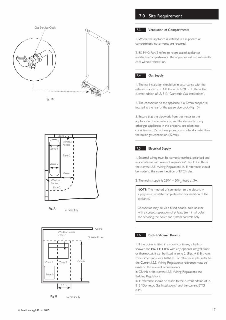
7.3 Ventilation of Compartments
1. Where the appliance is installed in a cupboard orcompartment, no air vents are required.
2. BS 5440: Part 2 refers to room sealed appliancesinstalled in compartments. The appliance will run sufficientlycool without ventilation.
7.4 Gas Supply
1. The gas installation should be in accordance with therelevant standards. In GB this is BS 6891. In IE this is thecurrent edition of I.S. 813 “Domestic Gas Installations”.
2. The connection to the appliance is a 22mm copper taillocated at the rear of the gas service cock (Fig. 10).
3. Ensure that the pipework from the meter to theappliance is of adequate size, and the demands of anyother gas appliances in the property are taken intoconsideration. Do not use pipes of a smaller diameter thanthe boiler gas connection (22mm).
7.5 Electrical Supply
1. External wiring must be correctly earthed, polarised andin accordance with relevant regulations/rules. In GB this isthe current I.E.E. Wiring Regulations. In IE reference shouldbe made to the current edition of ETCI rules.
2. The mains supply is 230V ~ 50Hz fused at 3A.
NOTE: The method of connection to the electricitysupply must facilitate complete electrical isolation of theappliance.
Connection may be via a fused double-pole isolatorwith a contact separation of at least 3mm in all polesand servicing the boiler and system controls only.
7.6 Bath & Shower Rooms
1. If the boiler is fitted in a room containing a bath orshower and NOT FITTED with any optional integral timeror thermostat, it can be fitted in zone 2, (Figs. A & B showszone dimensions for a bathtub. For other examples refer tothe Current I.E.E. Wiring Regulations) reference must bemade to the relevant requirements.In GB this is the current I.E.E. Wiring Regulations andBuilding Regulations.In IE reference should be made to the current edition of I.S.813 “Domestic Gas Installations” and the current ETCIrules.
Fig. 10
Gas Service Cock
Zone 2
Zone 1
Zone 0
Zone 2
Zone 2
WindowRecess
WindowRecess
0.6 m
Ceiling
Outside Zones
Zone 2Zone 1
Zone 0
2.25 m
Window RecessZone 2
0.6 m
Fig. A
Fig. B
In GB Only
In GB Only
18 © Baxi Heating UK Ltd 2015
7.0 Site Requirements
7.7 Condensate Drain
FAILURE TO INSTALL THE CONDENSATEDISCHARGE PIPEWORK CORRECTLY WILL AFFECTTHE RELIABLE OPERATION OF THE BOILER.
CAREFUL CONSIDERATION MUST BE GIVEN TO THEPOSSIBILITY OF THE PIPEWORK BEING SUBJECT TOFREEZING CONDITIONS AND APPROPRIATEMEASURES TAKEN TO PREVENT BLOCKAGE.CORRECT INSTALLATION IN ACCORDANCE WITHTHIS SECTION WILL CONSIDERABLY MINIMISE THELIKELIHOOD OF BLOCKAGE AND SUBSEQUENTBOILER LOCK-OUT.
A CONDENSATE DISCHARGE PUMP AND PIPE ‘TRACEHEATING’ ARE AVAILABLE AS ACCESSORIES - seeparagraphs 7.7.12 to 7.715 for further details.
The condensate discharge pipe MUST NOT RISE at anypoint along its length. There MUST be a fall of AT LEAST2.5° (50mm per metre) along the entire run EXCEPTwhen employing a suitable condensate pump in basementand cellar or similar applications.
The boiler condensate trap incorporates a seal of 75mm,therefore it is unnecessary to install an air break and trapin the discharge pipework.
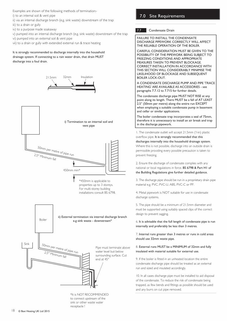
1. The condensate outlet will accept 21.5mm (3/4in) plasticoverflow pipe. It is strongly recommended that thisdischarges internally into the household drainage system. Where this is not possible, discharge into an outside drain ispermissible providing every possible precaution is taken toprevent freezing.
2. Ensure the discharge of condensate complies with anynational or local regulations in force. BS 6798 & Part H1 ofthe Building Regulations give further detailed guidance.
3. The discharge pipe should be run in a proprietary drain pipematerial e.g. PVC, PVC-U, ABS, PVC-C or PP.
4. Metal pipework is NOT suitable for use in condensatedischarge systems.
5. The pipe should be a minimum of 21.5mm diameter andmust be supported using suitably spaced clips of the correctdesign to prevent sagging.
6. It is advisable that the full length of condensate pipe is runinternally and preferably be less than 3 metres.
7. Internal runs greater than 3 metres or runs in cold areasshould use 32mm waste pipe.
8. External runs MUST be a MINIMUM of 32mm and fullyinsulated with material suitable for external use.
9. If the boiler is fitted in an unheated location the entirecondensate discharge pipe should be treated as an externalrun and sized and insulated accordingly.
10. In all cases discharge pipe must be installed to aid disposalof the condensate. To reduce the risk of condensate beingtrapped, as few bends and fittings as possible should be usedand any burrs on cut pipe removed.
21.5mm
2.5° Minimum fall
i) Termination to an internal soil andvent pipe
450mm min*
Boiler
2.5° Minimum fall
ii) External termination via internal discharge branch e.g sink waste - downstream*
SinkPipe must terminate abovewater level but belowsurrounding surface. Cutend at 45°
50mm per metre of pipe run
50mm per metre of pipe run
*450mm is applicable toproperties up to 3 storeys. For multi-storey buildinginstallations consult BS 6798.
Examples are shown of the following methods of termination:-i) to an internal soil & vent pipeii) via an internal discharge branch (e.g. sink waste) downstream of the trapiii) to a drain or gullyiv) to a purpose made soakawayv) pumped into an internal discharge branch (e.g. sink waste) downstream of the trapvi) pumped into an external soil & vent pipevii) to a drain or gully with extended external run & trace heating
It is strongly recommended to discharge internally into the household drainage system. If connecting to a rain water drain, that drain MUST discharge into a foul drain.
*It is NOT RECOMMENDEDto connect upstream of thesink or other waste waterreceptacle !
32mm Insulation
19© Baxi Heating UK Ltd 2015
7.0 Site Requirements
7.7 Condensate Drain (cont.)
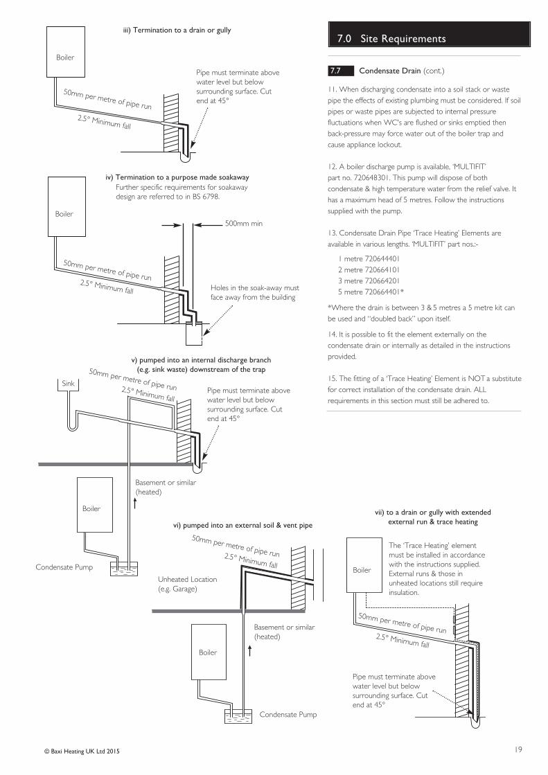
11. When discharging condensate into a soil stack or wastepipe the effects of existing plumbing must be considered. If soilpipes or waste pipes are subjected to internal pressurefluctuations when WC's are flushed or sinks emptied thenback-pressure may force water out of the boiler trap andcause appliance lockout.
12. A boiler discharge pump is available, ‘MULTIFIT’ part no. 720648301. This pump will dispose of bothcondensate & high temperature water from the relief valve. Ithas a maximum head of 5 metres. Follow the instructionssupplied with the pump.
13. Condensate Drain Pipe ‘Trace Heating’ Elements areavailable in various lengths. ‘MULTIFIT’ part nos.:-
1 metre 7206444012 metre 7206641013 metre 7206642015 metre 720664401*
*Where the drain is between 3 & 5 metres a 5 metre kit canbe used and “doubled back” upon itself.
14. It is possible to fit the element externally on thecondensate drain or internally as detailed in the instructionsprovided.
15. The fitting of a ‘Trace Heating’ Element is NOT a substitutefor correct installation of the condensate drain. ALLrequirements in this section must still be adhered to.
Boiler
2.5° Minimum fall
iii) Termination to a drain or gully
Boiler500mm min
2.5° Minimum fall
iv) Termination to a purpose made soakaway
Holes in the soak-away mustface away from the building
50mm per metre of pipe run
50mm per metre of pipe run
Further specific requirements for soakawaydesign are referred to in BS 6798.
Pipe must terminate abovewater level but belowsurrounding surface. Cutend at 45°
Boiler
vi) pumped into an external soil & vent pipe
2.5° Minimum fall
50mm per metre of pipe run
Condensate Pump
Unheated Location(e.g. Garage)
Basement or similar(heated)
Boiler
v) pumped into an internal discharge branch(e.g. sink waste) downstream of the trap
Pipe must terminate abovewater level but belowsurrounding surface. Cutend at 45°
2.5° Minimum fall
50mm per metre of pipe run
Condensate Pump
Sink
Basement or similar(heated)
Boiler
2.5° Minimum fall
50mm per metre of pipe run
Pipe must terminate abovewater level but belowsurrounding surface. Cutend at 45°
The ‘Trace Heating’ elementmust be installed in accordancewith the instructions supplied.External runs & those inunheated locations still requireinsulation.
vii) to a drain or gully with extended external run & trace heating
20
7.0 Site Requirements
© Baxi Heating UK Ltd 2015
7.8 Flue
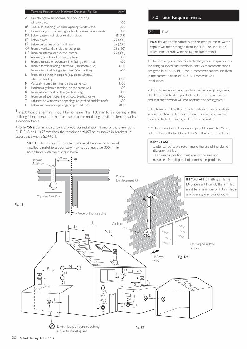
NOTE: Due to the nature of the boiler a plume of watervapour will be discharged from the flue. This should betaken into account when siting the flue terminal.
1. The following guidelines indicate the general requirementsfor siting balanced flue terminals. For GB recommendationsare given in BS 5440 Pt 1. For IE recommendations are givenin the current edition of I.S. 813 “Domestic GasInstallations”.
2. If the terminal discharges onto a pathway or passageway,check that combustion products will not cause a nuisanceand that the terminal will not obstruct the passageway.
3. If a terminal is less than 2 metres above a balcony, aboveground or above a flat roof to which people have access,then a suitable terminal guard must be provided.
4. * Reduction to the boundary is possible down to 25mmbut the flue deflector kit (part no. 5111068) must be fitted.
IMPORTANT:• Under car ports we recommend the use of the plume
displacement kit.• The terminal position must ensure the safe and
nuisance - free dispersal of combustion products.
N
I
I
G
F
M
I
AAF
H
J,K
DE
H
Likely flue positions requiring a flue terminal guard
C
RA
I
J,K
I
L
S
B
T
U
Fig. 12
Fig. 11
300 minTerminalAssembly
Top View Rear Flue
Property Boundary Line
NOTE: The distance from a fanned draught appliance terminalinstalled parallel to a boundary may not be less than 300mm inaccordance with the diagram below
Opening Windowor Door
150mmMIN.
IMPORTANT: If fitting a PlumeDisplacement Flue Kit, the air inletmust be a minimum of 150mm fromany opening windows or doors.
PlumeDisplacement Kit
Air Inlet
Fig. 12a
*
Terminal Position with Minimum Distance (Fig. 12) (mm)
A1 Directly below an opening, air brick, opening windows, etc. 300
B1 Above an opening, air brick, opening window etc. 300C1 Horizontally to an opening, air brick, opening window etc. 300D2 Below gutters, soil pipes or drain pipes. 25 (75)E2 Below eaves. 25 (200)F2 Below balconies or car port roof. 25 (200)G2 From a vertical drain pipe or soil pipe. 25 (150)H2 From an internal or external corner. 25 (300)I Above ground, roof or balcony level. 300J From a surface or boundary line facing a terminal. 600K From a terminal facing a terminal (Horizontal flue). 1200
From a terminal facing a terminal (Vertical flue). 600L From an opening in carport (e.g. door, window)
into the dwelling. 1200M Vertically from a terminal on the same wall. 1500N Horizontally from a terminal on the same wall. 300R From adjacent wall to flue (vertical only). 300S From an adjacent opening window (vertical only). 1000T Adjacent to windows or openings on pitched and flat roofs 600U Below windows or openings on pitched roofs 2000
1 In addition, the terminal should be no nearer than 150 mm to an opening in thebuilding fabric formed for the purpose of accommodating a built-in element such asa window frame.2 Only ONE 25mm clearance is allowed per installation. If one of the dimensionsD, E, F, G or H is 25mm then the remainder MUST be as shown in brackets, inaccordance with B.S.5440-1.
21
8.0 Flue Options
© Baxi Heating UK Ltd 2015
HorizontalFlues
Y
X
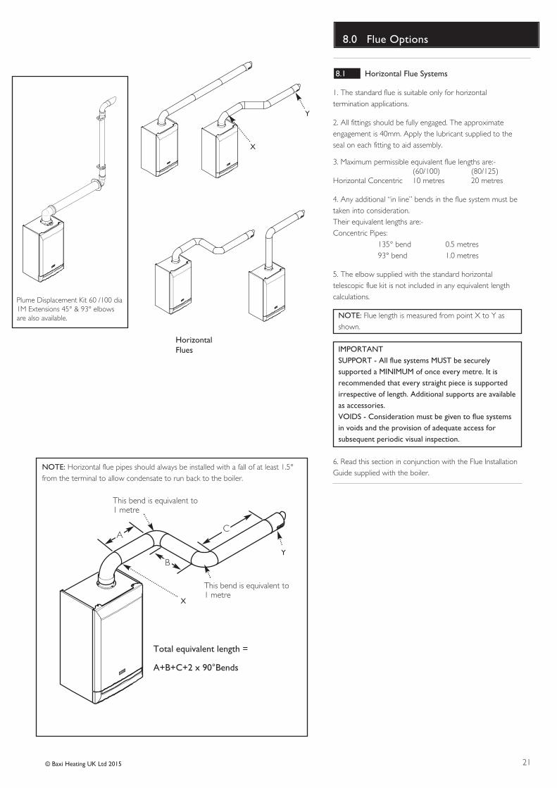
Plume Displacement Kit 60 /100 dia1M Extensions 45° & 93° elbowsare also available.
NOTE: Horizontal flue pipes should always be installed with a fall of at least 1.5°from the terminal to allow condensate to run back to the boiler.
Y
X
This bend is equivalent to1 metre
Total equivalent length =
A+B+C+2 x 90°Bends
B
AC
This bend is equivalent to1 metre
8.1 Horizontal Flue Systems
1. The standard flue is suitable only for horizontaltermination applications.
2. All fittings should be fully engaged. The approximateengagement is 40mm. Apply the lubricant supplied to theseal on each fitting to aid assembly.
3. Maximum permissible equivalent flue lengths are:-(60/100) (80/125)
Horizontal Concentric 10 metres 20 metres
4. Any additional “in line” bends in the flue system must betaken into consideration. Their equivalent lengths are:-Concentric Pipes:
135° bend 0.5 metres93° bend 1.0 metres
5. The elbow supplied with the standard horizontaltelescopic flue kit is not included in any equivalent lengthcalculations.
NOTE: Flue length is measured from point X to Y asshown.
IMPORTANTSUPPORT - All flue systems MUST be securelysupported a MINIMUM of once every metre. It isrecommended that every straight piece is supportedirrespective of length. Additional supports are availableas accessories.VOIDS - Consideration must be given to flue systemsin voids and the provision of adequate access forsubsequent periodic visual inspection.
6. Read this section in conjunction with the Flue InstallationGuide supplied with the boiler.
22 © Baxi Heating UK Ltd 2015
8.0 Flue Options
Fig. 13
Fig. 14
315mm
500mm
Flue Deflector
8.2 Flue Lengths
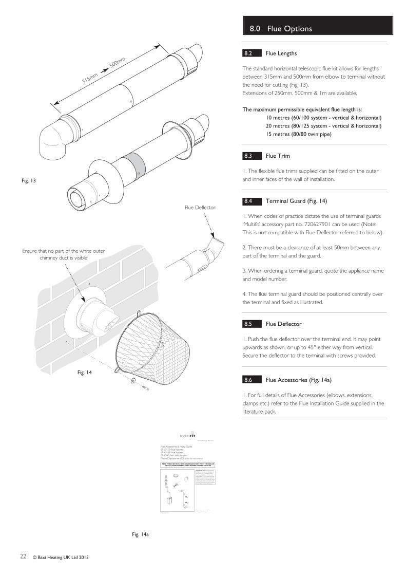
The standard horizontal telescopic flue kit allows for lengthsbetween 315mm and 500mm from elbow to terminal withoutthe need for cutting (Fig. 13).Extensions of 250mm, 500mm & 1m are available.
The maximum permissible equivalent flue length is: 10 metres (60/100 system - vertical & horizontal)20 metres (80/125 system - vertical & horizontal)15 metres (80/80 twin pipe)
8.3 Flue Trim
1. The flexible flue trims supplied can be fitted on the outerand inner faces of the wall of installation.
8.4 Terminal Guard (Fig. 14)
1. When codes of practice dictate the use of terminal guards‘Multifit’ accessory part no. 720627901 can be used (Note:This is not compatible with Flue Deflector referred to below).
2. There must be a clearance of at least 50mm between anypart of the terminal and the guard.
3. When ordering a terminal guard, quote the appliance nameand model number.
4. The flue terminal guard should be positioned centrally overthe terminal and fixed as illustrated.
8.5 Flue Deflector
1. Push the flue deflector over the terminal end. It may pointupwards as shown, or up to 45° either way from vertical.Secure the deflector to the terminal with screws provided.
8.6 Flue Accessories (Fig. 14a)
1. For full details of Flue Accessories (elbows, extensions,clamps etc.) refer to the Flue Installation Guide supplied in theliterature pack.
© Baxi Heating UK Ltd 2011
GU IDANC E NOT E S
Flue Accessories & Fitting GuideØ 60/100 Flue SystemsØ 80/125 Flue SystemsØ 80/80 Twin Flue SystemsPlume Displacement Kit (Ø 60/100 Flue Systems)
READ THESE INSTRUCTIONS IN CONJUNCTION WITH THE BOILERINSTALLATION INSTRUCTIONS BEFORE FITTING THE FLUE
Please leave these instructions with the Installation & Servicing Instructions.
IMPORTANT NOTE: This documentwill assist in the correct installation ofthe various flue & chimney systemsdescribed within. However, it is theresponsibility of the installer/Gas Saferegistered commissioning engineer toensure that the flue & chimney systemis fitted safely and in compliance withthe relevant standards and practices inforce in the country of installation.
Fig. 14a
Ensure that no part of the white outerchimney duct is visible
23© Baxi Heating UK Ltd 2015
Fig. 19
145mm
For Side Flue Exit
Central Heating Return
Flushing Tube
Wall Plate
Fig. 17
Flow Regulator
40 model only
Fig. 18
Fig. 15
Fig. 16
SNAP OFFLIFT HEREBOTH SIDES
To remove only the wall jig slide
banding to the edge and open flaps.
Slide the wall jig out of carton then
close the flaps. Slide banding back on.
Pre-plumbing
1.0 Introduction9.0 Installation
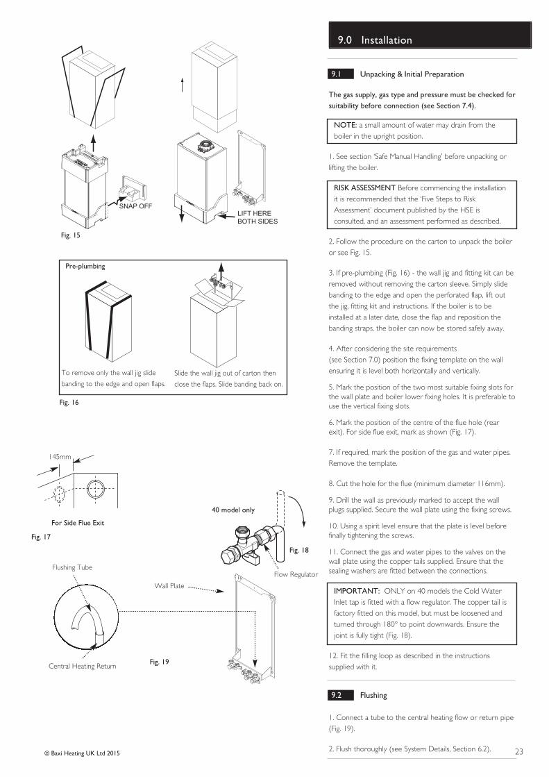
9.1 Unpacking & Initial Preparation
The gas supply, gas type and pressure must be checked forsuitability before connection (see Section 7.4).
NOTE: a small amount of water may drain from theboiler in the upright position.
1. See section ‘Safe Manual Handling’ before unpacking orlifting the boiler.
RISK ASSESSMENT Before commencing the installationit is recommended that the ‘Five Steps to RiskAssessment’ document published by the HSE isconsulted, and an assessment performed as described.
2. Follow the procedure on the carton to unpack the boileror see Fig. 15.
3. If pre-plumbing (Fig. 16) - the wall jig and fitting kit can beremoved without removing the carton sleeve. Simply slidebanding to the edge and open the perforated flap, lift outthe jig, fitting kit and instructions. If the boiler is to beinstalled at a later date, close the flap and reposition thebanding straps, the boiler can now be stored safely away.
4. After considering the site requirements (see Section 7.0) position the fixing template on the wallensuring it is level both horizontally and vertically.
5. Mark the position of the two most suitable fixing slots forthe wall plate and boiler lower fixing holes. It is preferable touse the vertical fixing slots.
6. Mark the position of the centre of the flue hole (rearexit). For side flue exit, mark as shown (Fig. 17).
7. If required, mark the position of the gas and water pipes.Remove the template.
8. Cut the hole for the flue (minimum diameter 116mm).
9. Drill the wall as previously marked to accept the wallplugs supplied. Secure the wall plate using the fixing screws.
10. Using a spirit level ensure that the plate is level beforefinally tightening the screws.
11. Connect the gas and water pipes to the valves on thewall plate using the copper tails supplied. Ensure that thesealing washers are fitted between the connections.
IMPORTANT: ONLY on 40 models the Cold WaterInlet tap is fitted with a flow regulator. The copper tail isfactory fitted on this model, but must be loosened andturned through 180° to point downwards. Ensure thejoint is fully tight (Fig. 18).
12. Fit the filling loop as described in the instructionssupplied with it.
9.2 Flushing
1. Connect a tube to the central heating flow or return pipe(Fig. 19).
2. Flush thoroughly (see System Details, Section 6.2).
24 © Baxi Heating UK Ltd 2015
9.0 Installation
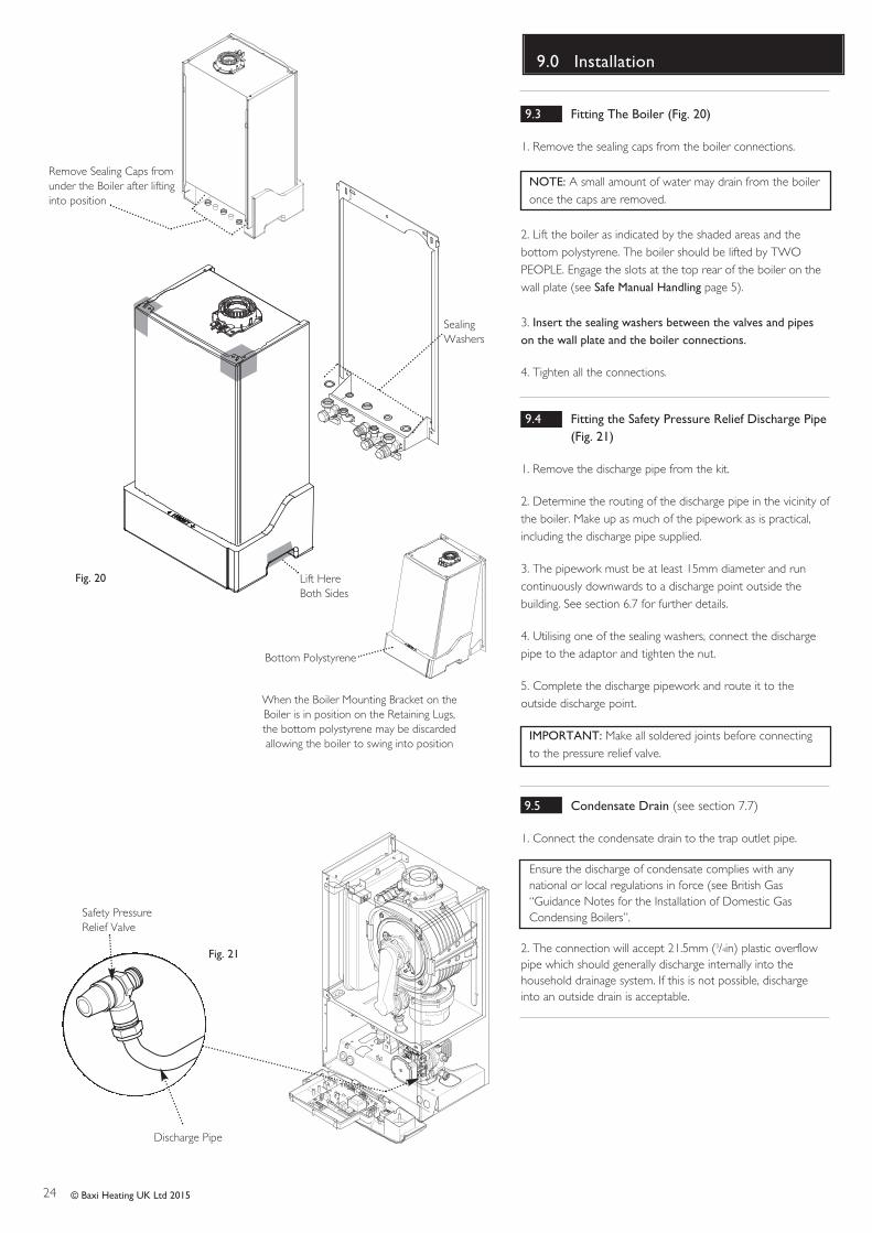
9.3 Fitting The Boiler (Fig. 20)
1. Remove the sealing caps from the boiler connections.
NOTE: A small amount of water may drain from the boileronce the caps are removed.
2. Lift the boiler as indicated by the shaded areas and thebottom polystyrene. The boiler should be lifted by TWOPEOPLE. Engage the slots at the top rear of the boiler on thewall plate (see Safe Manual Handling page 5).
3. Insert the sealing washers between the valves and pipeson the wall plate and the boiler connections.
4. Tighten all the connections.
9.4 Fitting the Safety Pressure Relief Discharge Pipe (Fig. 21)
1. Remove the discharge pipe from the kit.
2. Determine the routing of the discharge pipe in the vicinity ofthe boiler. Make up as much of the pipework as is practical,including the discharge pipe supplied.
3. The pipework must be at least 15mm diameter and runcontinuously downwards to a discharge point outside thebuilding. See section 6.7 for further details.
4. Utilising one of the sealing washers, connect the dischargepipe to the adaptor and tighten the nut.
5. Complete the discharge pipework and route it to theoutside discharge point.
IMPORTANT: Make all soldered joints before connectingto the pressure relief valve.
9.5 Condensate Drain (see section 7.7)
1. Connect the condensate drain to the trap outlet pipe.
Ensure the discharge of condensate complies with anynational or local regulations in force (see British Gas“Guidance Notes for the Installation of Domestic GasCondensing Boilers”.
2. The connection will accept 21.5mm (3/4in) plastic overflowpipe which should generally discharge internally into thehousehold drainage system. If this is not possible, dischargeinto an outside drain is acceptable.
Fig. 21
Safety PressureRelief Valve
Discharge Pipe
Fig. 20
SealingWashers
Remove Sealing Caps fromunder the Boiler after liftinginto position
Lift HereBoth Sides
When the Boiler Mounting Bracket on theBoiler is in position on the Retaining Lugs,the bottom polystyrene may be discardedallowing the boiler to swing into position
Bottom Polystyrene
25© Baxi Heating UK Ltd 2015
9.0 Installation
Fig. 22
Fig. 24
315mm
500mm
Terminal Assembly
Connection Assembly
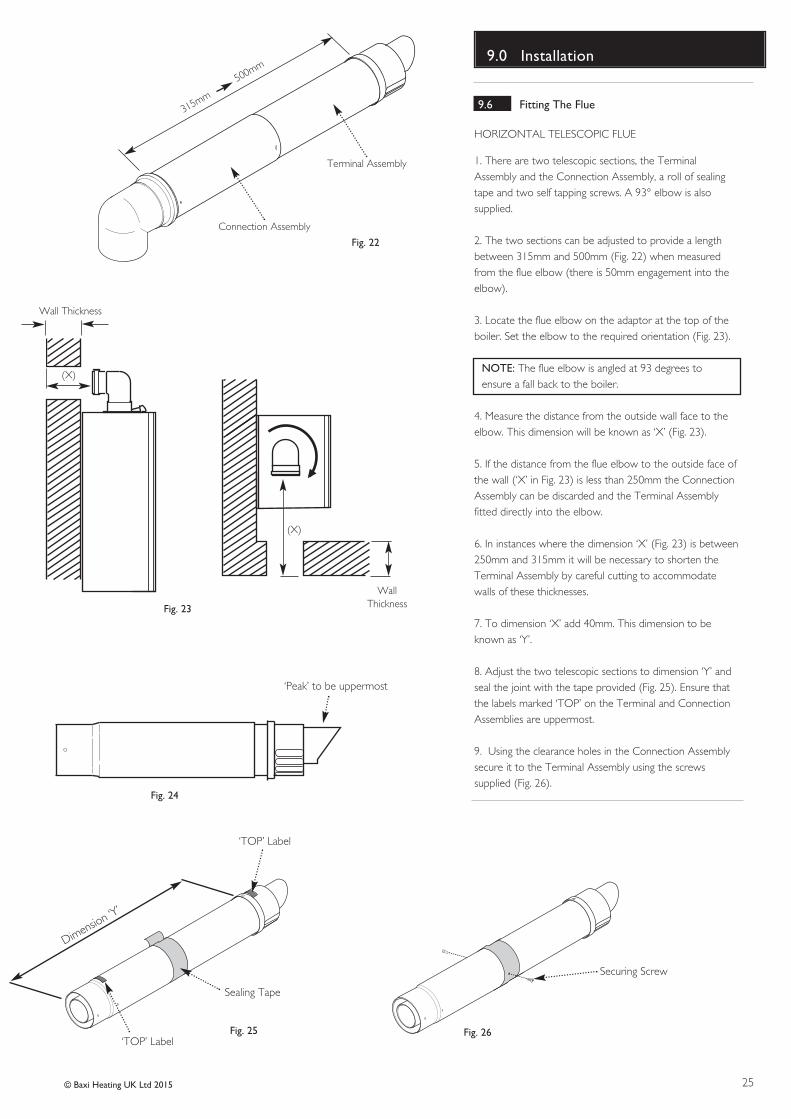
9.6 Fitting The Flue
HORIZONTAL TELESCOPIC FLUE
1. There are two telescopic sections, the TerminalAssembly and the Connection Assembly, a roll of sealingtape and two self tapping screws. A 93° elbow is alsosupplied.
2. The two sections can be adjusted to provide a lengthbetween 315mm and 500mm (Fig. 22) when measuredfrom the flue elbow (there is 50mm engagement into theelbow).
3. Locate the flue elbow on the adaptor at the top of theboiler. Set the elbow to the required orientation (Fig. 23).
NOTE: The flue elbow is angled at 93 degrees toensure a fall back to the boiler.
4. Measure the distance from the outside wall face to theelbow. This dimension will be known as ‘X’ (Fig. 23).
5. If the distance from the flue elbow to the outside face ofthe wall (‘X’ in Fig. 23) is less than 250mm the ConnectionAssembly can be discarded and the Terminal Assemblyfitted directly into the elbow.
6. In instances where the dimension ‘X’ (Fig. 23) is between250mm and 315mm it will be necessary to shorten theTerminal Assembly by careful cutting to accommodatewalls of these thicknesses.
7. To dimension ‘X’ add 40mm. This dimension to beknown as ‘Y’.
8. Adjust the two telescopic sections to dimension ‘Y’ andseal the joint with the tape provided (Fig. 25). Ensure thatthe labels marked ‘TOP’ on the Terminal and ConnectionAssemblies are uppermost.
9. Using the clearance holes in the Connection Assemblysecure it to the Terminal Assembly using the screwssupplied (Fig. 26).
WallThickness
(X)
Wall Thickness
(X)
Fig. 26
‘Peak’ to be uppermost
Dimension ‘Y’
Securing Screw
Sealing Tape
‘TOP’ Label
‘TOP’ Label
Fig. 23
Fig. 25
26 © Baxi Heating UK Ltd 2015
9.0 Installation
Slots at bottomFig. 29
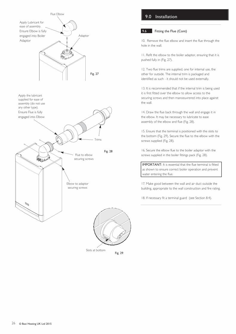
Flue Elbow
Adaptor
Apply Lubricant forease of assembly.
Ensure Elbow is fullyengaged into BoilerAdaptor
Apply the lubricantsupplied for ease ofassembly (do not useany other type).
Ensure Flue is fullyengaged into Elbow
Elbow to adaptorsecuring screws
Flue to elbowsecuring screws
Trims
9.6 Fitting the Flue (Cont)
10. Remove the flue elbow and insert the flue through thehole in the wall.
11. Refit the elbow to the boiler adaptor, ensuring that it ispushed fully in (Fig. 27).
12. Two flue trims are supplied, one for internal use, theother for outside. The internal trim is packaged andidentified as such - it should not be used externally.
13. It is recommended that if the internal trim is being usedit is first fitted over the elbow to allow access to thesecuring screws and then manoeuvrered into place againstthe wall.
14. Draw the flue back through the wall and engage it inthe elbow. It may be necessary to lubricate to easeassembly of the elbow and flue (Fig. 28).
15. Ensure that the terminal is positioned with the slots tothe bottom (Fig. 29). Secure the flue to the elbow with thescrews supplied (Fig. 28).
16. Secure the elbow flue to the boiler adaptor with thescrews supplied in the boiler fittings pack (Fig. 28).
IMPORTANT: It is essential that the flue terminal is fittedas shown to ensure correct boiler operation and preventwater entering the flue.
17. Make good between the wall and air duct outside thebuilding, appropriate to the wall construction and fire rating.
18. If necessary fit a terminal guard (see Section 8.4).
Fig. 27
Fig. 28
27© Baxi Heating UK Ltd 2015
9.0 Installation
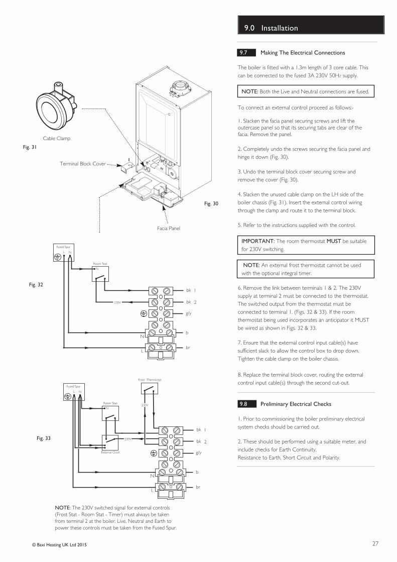
9.7 Making The Electrical Connections
The boiler is fitted with a 1.3m length of 3 core cable. Thiscan be connected to the fused 3A 230V 50HZ supply.
NOTE: Both the Live and Neutral connections are fused.
To connect an external control proceed as follows:-
1. Slacken the facia panel securing screws and lift theoutercase panel so that its securing tabs are clear of thefacia. Remove the panel.
2. Completely undo the screws securing the facia panel andhinge it down (Fig. 30).
3. Undo the terminal block cover securing screw andremove the cover (Fig. 30).
4. Slacken the unused cable clamp on the LH side of theboiler chassis (Fig. 31). Insert the external control wiringthrough the clamp and route it to the terminal block.
5. Refer to the instructions supplied with the control.
IMPORTANT: The room thermostat MUST be suitablefor 230V switching.
NOTE: An external frost thermostat cannot be usedwith the optional integral timer.
6. Remove the link between terminals 1 & 2. The 230Vsupply at terminal 2 must be connected to the thermostat.The switched output from the thermostat must beconnected to terminal 1. (Figs. 32 & 33). If the roomthermostat being used incorporates an anticipator it MUSTbe wired as shown in Figs. 32 & 33.
7. Ensure that the external control input cable(s) havesufficient slack to allow the control box to drop down.Tighten the cable clamp on the boiler chassis.
8. Replace the terminal block cover, routing the externalcontrol input cable(s) through the second cut-out.
9.8 Preliminary Electrical Checks
1. Prior to commissioning the boiler preliminary electricalsystem checks should be carried out.
2. These should be performed using a suitable meter, andinclude checks for Earth Continuity,Resistance to Earth, Short Circuit and Polarity.
b
br
bk
bk
g/y
1
N
L
2
N
N
L
Room ‘Stat
Fused Spur
230V
Fig. 31
Fig. 33
Cable Clamp
Terminal Block Cover
Facia Panel
b
br
bk
bk
g/y
1
N
L
Frost
Thermostat
External Clock
2
N
N
L
Room ‘Stat
Fused Spur
230V
230V
NOTE: The 230V switched signal for external controls(Frost Stat - Room Stat - Timer) must always be takenfrom terminal 2 at the boiler. Live, Neutral and Earth topower these controls must be taken from the Fused Spur.
Fig. 32
Fig. 30
28 © Baxi Heating UK Ltd 2015
10.0 Commissioning
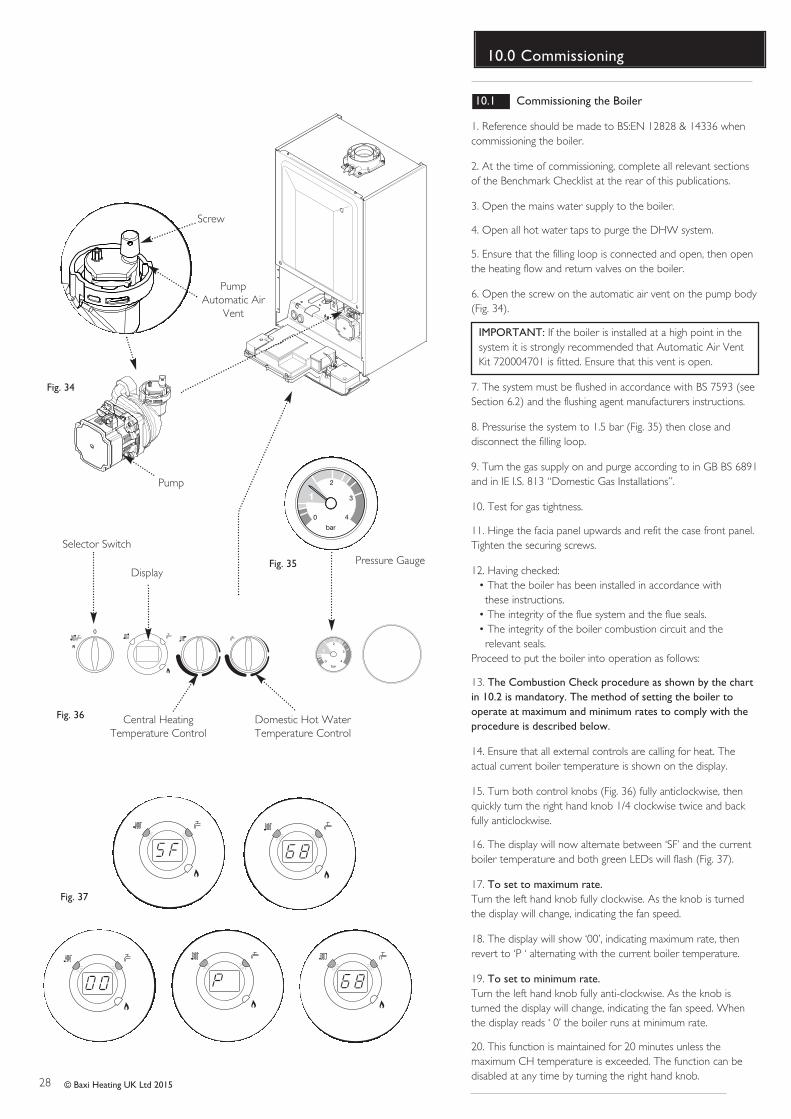
10.1 Commissioning the Boiler
1. Reference should be made to BS:EN 12828 & 14336 whencommissioning the boiler.
2. At the time of commissioning, complete all relevant sectionsof the Benchmark Checklist at the rear of this publications.
3. Open the mains water supply to the boiler.
4. Open all hot water taps to purge the DHW system.
5. Ensure that the filling loop is connected and open, then openthe heating flow and return valves on the boiler.
6. Open the screw on the automatic air vent on the pump body(Fig. 34).
IMPORTANT: If the boiler is installed at a high point in thesystem it is strongly recommended that Automatic Air VentKit 720004701 is fitted. Ensure that this vent is open.
7. The system must be flushed in accordance with BS 7593 (seeSection 6.2) and the flushing agent manufacturers instructions.
8. Pressurise the system to 1.5 bar (Fig. 35) then close anddisconnect the filling loop.
9. Turn the gas supply on and purge according to in GB BS 6891and in IE I.S. 813 “Domestic Gas Installations”.
10. Test for gas tightness.
11. Hinge the facia panel upwards and refit the case front panel.Tighten the securing screws.
12. Having checked:• That the boiler has been installed in accordance with
these instructions.• The integrity of the flue system and the flue seals.• The integrity of the boiler combustion circuit and the
relevant seals.Proceed to put the boiler into operation as follows:
13. The Combustion Check procedure as shown by the chartin 10.2 is mandatory. The method of setting the boiler tooperate at maximum and minimum rates to comply with theprocedure is described below.
14. Ensure that all external controls are calling for heat. Theactual current boiler temperature is shown on the display.
15. Turn both control knobs (Fig. 36) fully anticlockwise, thenquickly turn the right hand knob 1/4 clockwise twice and backfully anticlockwise.
16. The display will now alternate between ‘SF’ and the currentboiler temperature and both green LEDs will flash (Fig. 37).
17. To set to maximum rate.Turn the left hand knob fully clockwise. As the knob is turnedthe display will change, indicating the fan speed.
18. The display will show ‘00’, indicating maximum rate, thenrevert to ‘P ‘ alternating with the current boiler temperature.
19. To set to minimum rate.Turn the left hand knob fully anti-clockwise. As the knob isturned the display will change, indicating the fan speed. Whenthe display reads ‘ 0’ the boiler runs at minimum rate.
20. This function is maintained for 20 minutes unless themaximum CH temperature is exceeded. The function can bedisabled at any time by turning the right hand knob.
PumpAutomatic Air
Vent
Pressure Gauge
Screw
bar
0
1
2
3
4
Fig. 34
Selector Switch
Central Heating Temperature Control
Domestic Hot Water Temperature Control
bar
0
1
2
3
4
Pump
Fig. 36
Fig. 35Display
Fig. 37
29© Baxi Heating UK Ltd 2015
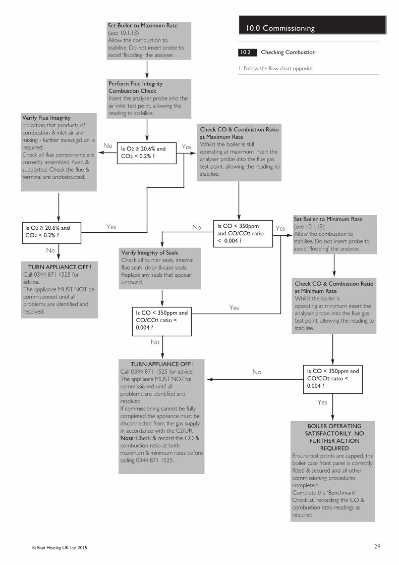
10.0 CommissioningSet Boiler to Maximum Rate(see 10.1.13)Allow the combustion to stabilise. Do not insert probe toavoid ‘flooding’ the analyser.
Perform Flue Integrity Combustion CheckInsert the analyser probe into theair inlet test point, allowing thereading to stabilise.
Is O2 � 20.6% andCO2 < 0.2% ?
Verify Flue IntegrityIndication that products ofcombustion & inlet air are mixing - further investigation isrequired.Check all flue components arecorrectly assembled, fixed &supported. Check the flue &terminal are unobstructed.
Is O2 � 20.6% andCO2 < 0.2% ?
TURN APPLIANCE OFF !Call 0344 871 1525 foradvice.The appliance MUST NOT becommissioned until all problems are identified andresolved.
Check CO & Combustion Ratioat Maximum RateWhilst the boiler is still operating at maximum insert theanalyser probe into the flue gastest point, allowing the reading tostabilise.
Is CO < 350ppmand CO/CO2 ratio< 0.004 ?
Verify Integrity of SealsCheck all burner seals, internalflue seals, door & case seals.Replace any seals that appearunsound.
Is CO < 350ppm andCO/CO2 ratio <0.004 ?
TURN APPLIANCE OFF !Call 0344 871 1525 for advice.The appliance MUST NOT becommissioned until all problems are identified and resolved.If commissioning cannot be fullycompleted the appliance must bedisconnected from the gas supplyin accordance with the GSIUR.Note: Check & record the CO &combustion ratio at bothmaximum & minimum rates beforecalling 0344 871 1525.
Set Boiler to Minimum Rate(see 10.1.19)Allow the combustion to stabilise. Do not insert probe toavoid ‘flooding’ the analyser.
YesNo
No Yes
No
Yes
Check CO & Combustion Ratioat Minimum RateWhilst the boiler is operating at minimum insert theanalyser probe into the flue gastest point, allowing the reading tostabilise.
Yes
No
Is CO < 350ppm andCO/CO2 ratio <0.004 ?
No
Yes
BOILER OPERATING SATISFACTORILY. NO
FURTHER ACTION REQUIRED
Ensure test points are capped, theboiler case front panel is correctlyfitted & secured and all othercommissioning procedurescompleted.Complete the ‘Benchmark’Checklist, recording the CO &combustion ratio readings asrequired.
10.2 Checking Combustion
1. Follow the flow chart opposite.
30 © Baxi Heating UK Ltd 2007
10.0 Commissioning
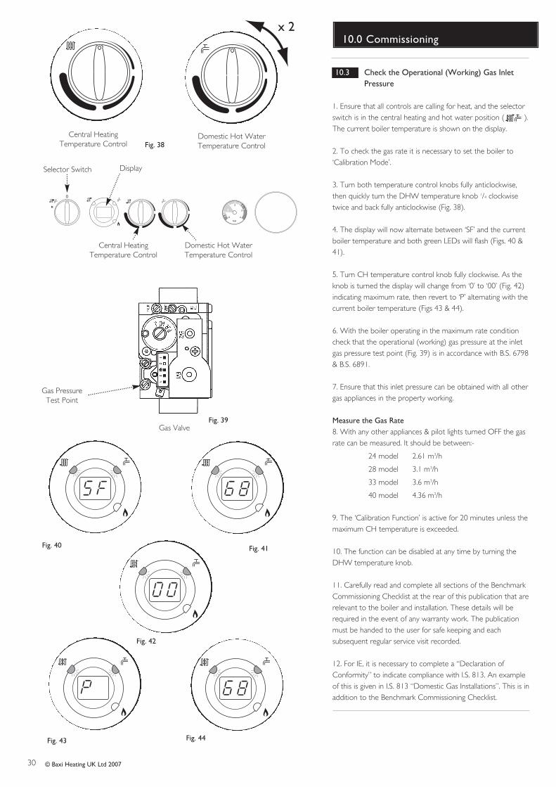
10.3 Check the Operational (Working) Gas Inlet
Pressure
1. Ensure that all controls are calling for heat, and the selectorswitch is in the central heating and hot water position ( ).The current boiler temperature is shown on the display.
2. To check the gas rate it is necessary to set the boiler to‘Calibration Mode’.
3. Turn both temperature control knobs fully anticlockwise,then quickly turn the DHW temperature knob 1/4 clockwisetwice and back fully anticlockwise (Fig. 38).
4. The display will now alternate between ‘SF’ and the currentboiler temperature and both green LEDs will flash (Figs. 40 &41).
5. Turn CH temperature control knob fully clockwise. As theknob is turned the display will change from ‘0’ to ‘00’ (Fig. 42)indicating maximum rate, then revert to ‘P’ alternating with thecurrent boiler temperature (Figs 43 & 44).
6. With the boiler operating in the maximum rate conditioncheck that the operational (working) gas pressure at the inletgas pressure test point (Fig. 39) is in accordance with B.S. 6798& B.S. 6891.
7. Ensure that this inlet pressure can be obtained with all othergas appliances in the property working.
Measure the Gas Rate8. With any other appliances & pilot lights turned OFF the gasrate can be measured. It should be between:-
24 model 2.61 m3/h
28 model 3.1 m3/h
33 model 3.6 m3/h
40 model 4.36 m3/h
9. The ‘Calibration Function’ is active for 20 minutes unless themaximum CH temperature is exceeded.
10. The function can be disabled at any time by turning theDHW temperature knob.
11. Carefully read and complete all sections of the BenchmarkCommissioning Checklist at the rear of this publication that arerelevant to the boiler and installation. These details will berequired in the event of any warranty work. The publicationmust be handed to the user for safe keeping and eachsubsequent regular service visit recorded.
12. For IE, it is necessary to complete a “Declaration ofConformity” to indicate compliance with I.S. 813. An exampleof this is given in I.S. 813 “Domestic Gas Installations”. This is inaddition to the Benchmark Commissioning Checklist.
Selector Switch Display
bar
0
1
2
3
4
Central Heating Temperature Control
Domestic Hot Water Temperature Control
Fig. 40 Fig. 41
Fig. 42
Fig. 43 Fig. 44
Central Heating Temperature Control
Domestic Hot Water Temperature ControlFig. 38
x 2
Gas Valve
Gas PressureTest Point
Fig. 39
31© Baxi Heating UK Ltd 2015
11.0 Completion
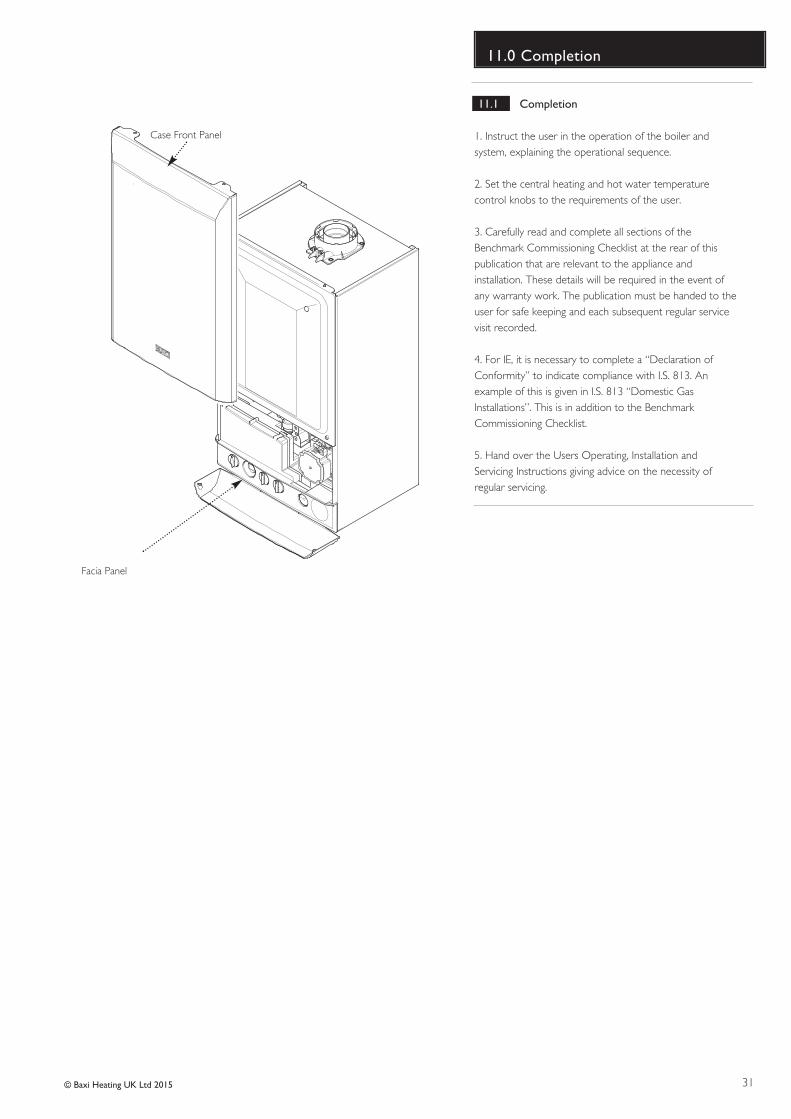
11.1 Completion
1. Instruct the user in the operation of the boiler andsystem, explaining the operational sequence.
2. Set the central heating and hot water temperaturecontrol knobs to the requirements of the user.
3. Carefully read and complete all sections of theBenchmark Commissioning Checklist at the rear of thispublication that are relevant to the appliance andinstallation. These details will be required in the event ofany warranty work. The publication must be handed to theuser for safe keeping and each subsequent regular servicevisit recorded.
4. For IE, it is necessary to complete a “Declaration ofConformity” to indicate compliance with I.S. 813. Anexample of this is given in I.S. 813 “Domestic GasInstallations”. This is in addition to the BenchmarkCommissioning Checklist.
5. Hand over the Users Operating, Installation andServicing Instructions giving advice on the necessity ofregular servicing.
Facia Panel
Case Front Panel
32 © Baxi Heating UK Ltd 2015
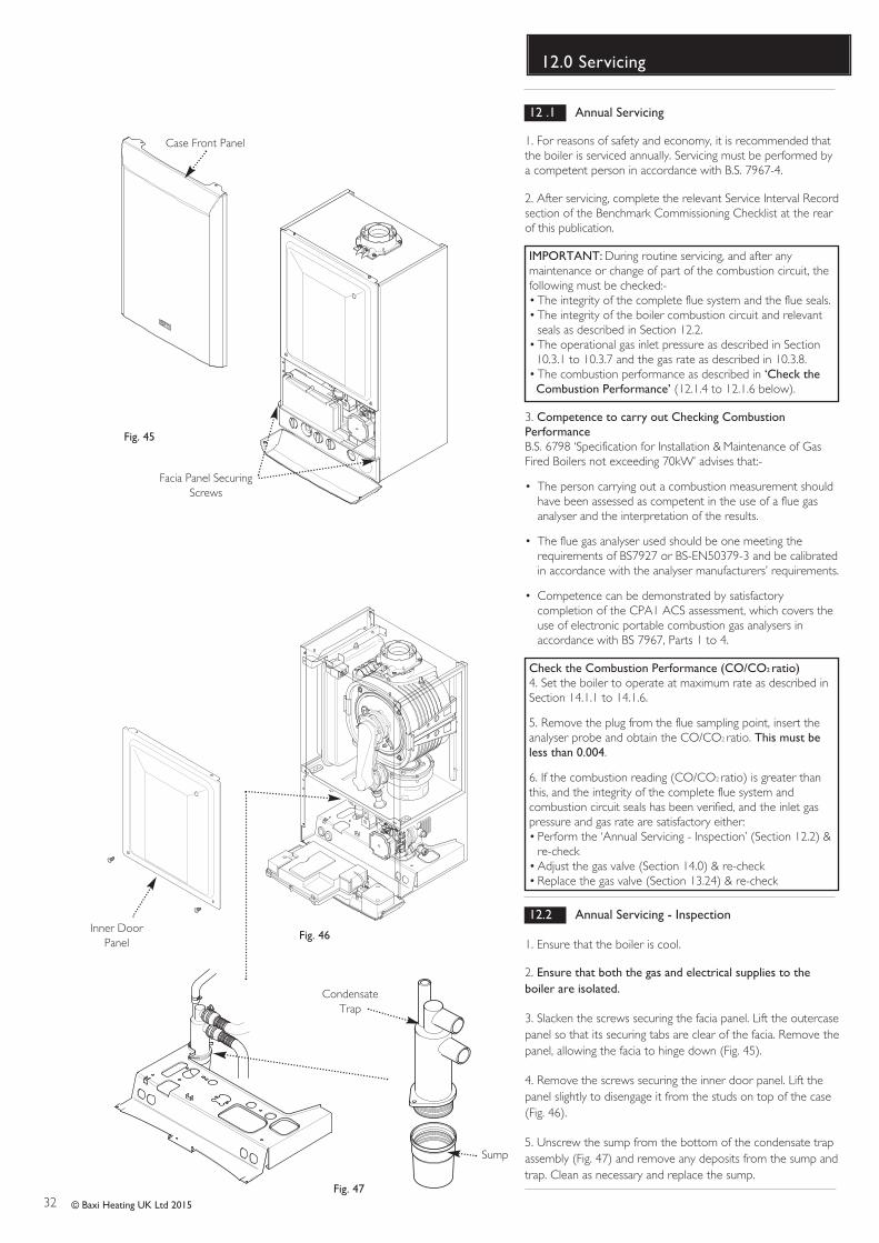
12.0 Servicing
Case Front Panel
Fig. 45
Facia Panel SecuringScrews
Fig. 46Inner Door
Panel
CondensateTrap
Sump
12 .1 Annual Servicing
1. For reasons of safety and economy, it is recommended thatthe boiler is serviced annually. Servicing must be performed bya competent person in accordance with B.S. 7967-4.
2. After servicing, complete the relevant Service Interval Recordsection of the Benchmark Commissioning Checklist at the rearof this publication.
IMPORTANT: During routine servicing, and after anymaintenance or change of part of the combustion circuit, thefollowing must be checked:-• The integrity of the complete flue system and the flue seals.• The integrity of the boiler combustion circuit and relevant
seals as described in Section 12.2.• The operational gas inlet pressure as described in Section
10.3.1 to 10.3.7 and the gas rate as described in 10.3.8.• The combustion performance as described in ‘Check the
Combustion Performance’ (12.1.4 to 12.1.6 below).
3. Competence to carry out Checking CombustionPerformanceB.S. 6798 ‘Specification for Installation & Maintenance of GasFired Boilers not exceeding 70kW’ advises that:-
• The person carrying out a combustion measurement should have been assessed as competent in the use of a flue gas analyser and the interpretation of the results.
• The flue gas analyser used should be one meeting the requirements of BS7927 or BS-EN50379-3 and be calibratedin accordance with the analyser manufacturers’ requirements.
• Competence can be demonstrated by satisfactory completion of the CPA1 ACS assessment, which covers the use of electronic portable combustion gas analysers in accordance with BS 7967, Parts 1 to 4.
Check the Combustion Performance (CO/CO2 ratio)4. Set the boiler to operate at maximum rate as described inSection 14.1.1 to 14.1.6.
5. Remove the plug from the flue sampling point, insert theanalyser probe and obtain the CO/CO2 ratio. This must beless than 0.004.
6. If the combustion reading (CO/CO2 ratio) is greater thanthis, and the integrity of the complete flue system andcombustion circuit seals has been verified, and the inlet gaspressure and gas rate are satisfactory either:• Perform the ‘Annual Servicing - Inspection’ (Section 12.2) &
re-check• Adjust the gas valve (Section 14.0) & re-check• Replace the gas valve (Section 13.24) & re-check
12.2 Annual Servicing - Inspection
1. Ensure that the boiler is cool.
2. Ensure that both the gas and electrical supplies to theboiler are isolated.
3. Slacken the screws securing the facia panel. Lift the outercasepanel so that its securing tabs are clear of the facia. Remove thepanel, allowing the facia to hinge down (Fig. 45).
4. Remove the screws securing the inner door panel. Lift thepanel slightly to disengage it from the studs on top of the case(Fig. 46).
5. Unscrew the sump from the bottom of the condensate trapassembly (Fig. 47) and remove any deposits from the sump andtrap. Clean as necessary and replace the sump.
Fig. 47
33© Baxi Heating UK Ltd 2015
12.0 Servicing
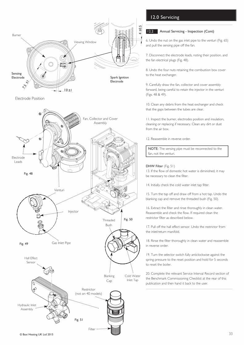
12.2 Annual Servicing - Inspection (Cont)
6. Undo the nut on the gas inlet pipe to the venturi (Fig. 65)and pull the sensing pipe off the fan.
7. Disconnect the electrode leads, noting their position, andthe fan electrical plugs (Fig. 48).
8. Undo the four nuts retaining the combustion box coverto the heat exchanger.
9. Carefully draw the fan, collector and cover assemblyforward, being careful to retain the injector in the venturi(Figs. 48 & 49).
10. Clean any debris from the heat exchanger and checkthat the gaps between the tubes are clear.
11. Inspect the burner, electrodes position and insulation,cleaning or replacing if necessary. Clean any dirt or dustfrom the air box.
12. Reassemble in reverse order.
NOTE: The sensing pipe must be reconnected to thefan, not the venturi.
DHW Filter (Fig. 51)13. If the flow of domestic hot water is diminished, it maybe necessary to clean the filter.
14. Initially check the cold water inlet tap filter.
15. Turn the tap off and draw off from a hot tap. Undo theblanking cap and remove the threaded bush (Fig. 50).
16. Extract the filter and rinse thoroughly in clean water.Reassemble and check the flow. If required clean therestrictor filter as described below.
17. Pull off the hall effect sensor. Undo the restrictor fromthe inlet/return manifold.
18. Rinse the filter thoroughly in clean water and reassemblein reverse order.
19. Turn the selector switch fully anticlockwise against thespring pressure to the reset position and hold for 5 secondsto reset the boiler.
20. Complete the relevant Service Interval Record section ofthe Benchmark Commissioning Checklist at the rear of thispublication and then hand it back to the user.
Fig. 48
Cold WaterInlet Tap
Blanking
Cap
Threaded
Bush
Fig. 50
Fig. 49
Hall EffectSensor
Hydraulic InletAssembly
Fig. 51
Gas Inlet Pipe
Venturi
Injector
Restrictor(not on 40 models)
Fan, Collector and CoverAssembly
ElectrodeLeads
7.5
±1
4±0
.5
10 ±1
Spark Ignition Electrode
Sensing Electrode
Electrode Position
Viewing Window
Burner
Filter
34 © Baxi Heating UK Ltd 2015
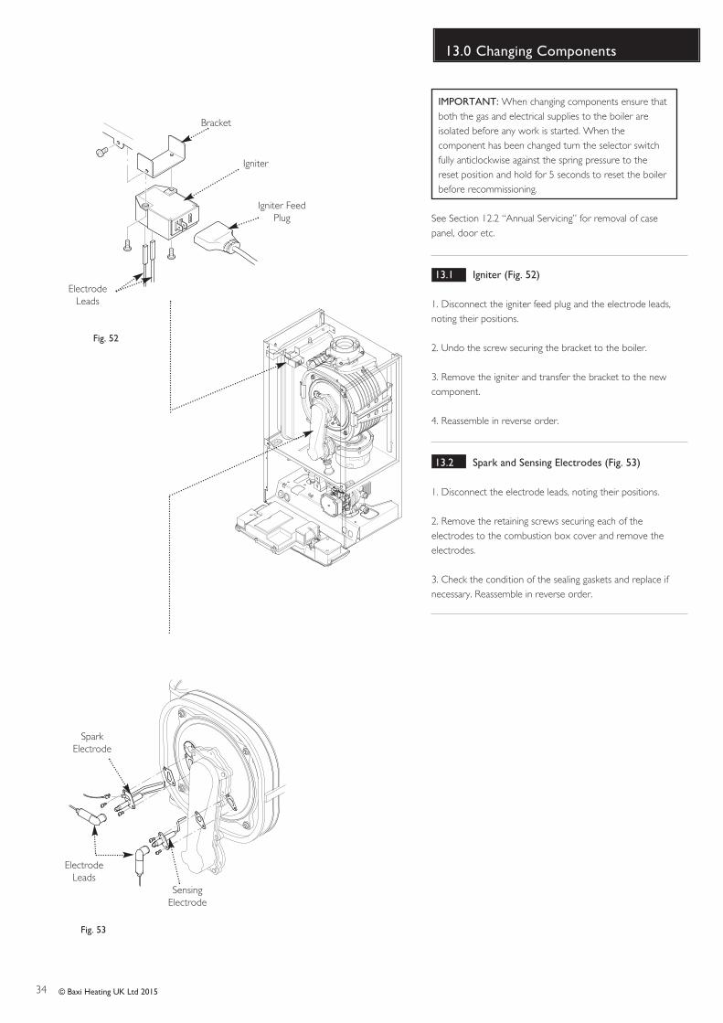
13.0 Changing Components
IMPORTANT: When changing components ensure thatboth the gas and electrical supplies to the boiler areisolated before any work is started. When thecomponent has been changed turn the selector switchfully anticlockwise against the spring pressure to thereset position and hold for 5 seconds to reset the boilerbefore recommissioning.
See Section 12.2 “Annual Servicing” for removal of casepanel, door etc.
13.1 Igniter (Fig. 52)
1. Disconnect the igniter feed plug and the electrode leads,noting their positions.
2. Undo the screw securing the bracket to the boiler.
3. Remove the igniter and transfer the bracket to the newcomponent.
4. Reassemble in reverse order.
13.2 Spark and Sensing Electrodes (Fig. 53)
1. Disconnect the electrode leads, noting their positions.
2. Remove the retaining screws securing each of theelectrodes to the combustion box cover and remove theelectrodes.
3. Check the condition of the sealing gaskets and replace ifnecessary. Reassemble in reverse order.
Fig. 52
Igniter
Igniter FeedPlug
ElectrodeLeads
Bracket
Fig. 53
SparkElectrode
SensingElectrode
ElectrodeLeads
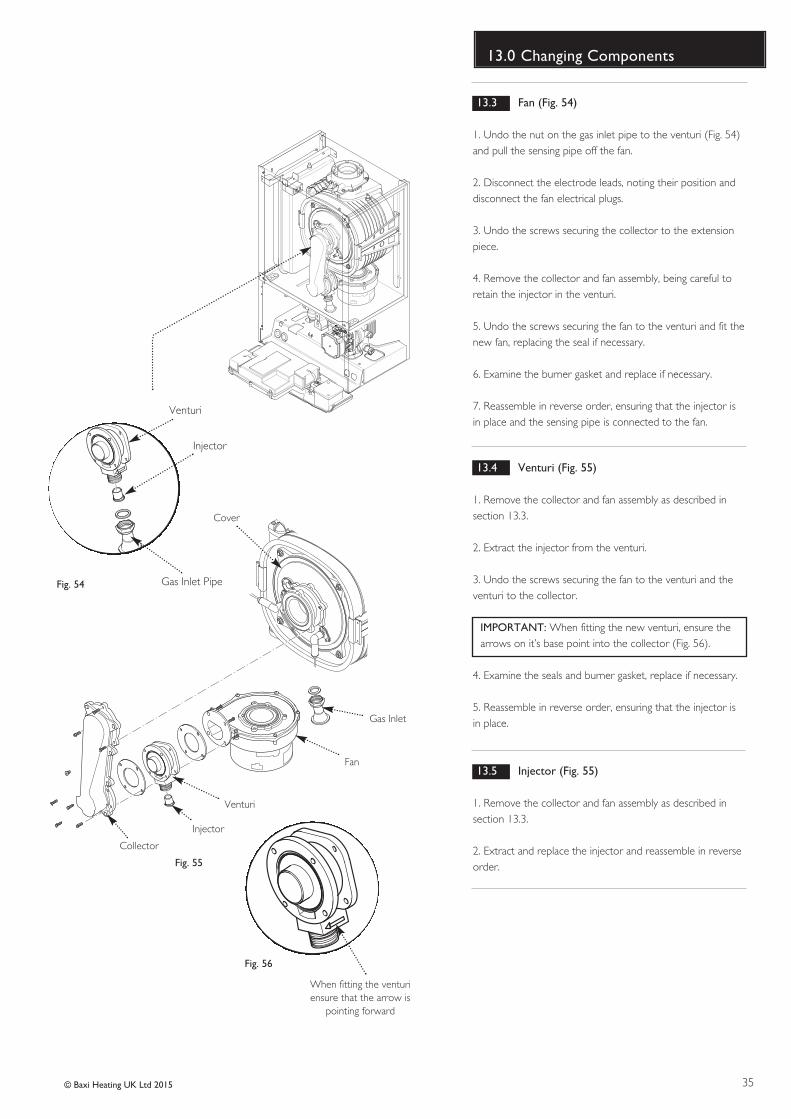
35© Baxi Heating UK Ltd 2015
13.0 Changing Components
13.3 Fan (Fig. 54)
1. Undo the nut on the gas inlet pipe to the venturi (Fig. 54)and pull the sensing pipe off the fan.
2. Disconnect the electrode leads, noting their position anddisconnect the fan electrical plugs.
3. Undo the screws securing the collector to the extensionpiece.
4. Remove the collector and fan assembly, being careful toretain the injector in the venturi.
5. Undo the screws securing the fan to the venturi and fit thenew fan, replacing the seal if necessary.
6. Examine the burner gasket and replace if necessary.
7. Reassemble in reverse order, ensuring that the injector isin place and the sensing pipe is connected to the fan.
13.4 Venturi (Fig. 55)
1. Remove the collector and fan assembly as described insection 13.3.
2. Extract the injector from the venturi.
3. Undo the screws securing the fan to the venturi and theventuri to the collector.
IMPORTANT: When fitting the new venturi, ensure thearrows on it’s base point into the collector (Fig. 56).
4. Examine the seals and burner gasket, replace if necessary.
5. Reassemble in reverse order, ensuring that the injector isin place.
13.5 Injector (Fig. 55)
1. Remove the collector and fan assembly as described insection 13.3.
2. Extract and replace the injector and reassemble in reverseorder.
Cover
Gas Inlet
Fan
Venturi
Injector
Collector
When fitting the venturiensure that the arrow is
pointing forward
Fig. 55
Fig. 54 Gas Inlet Pipe
Venturi
Injector
Fig. 56
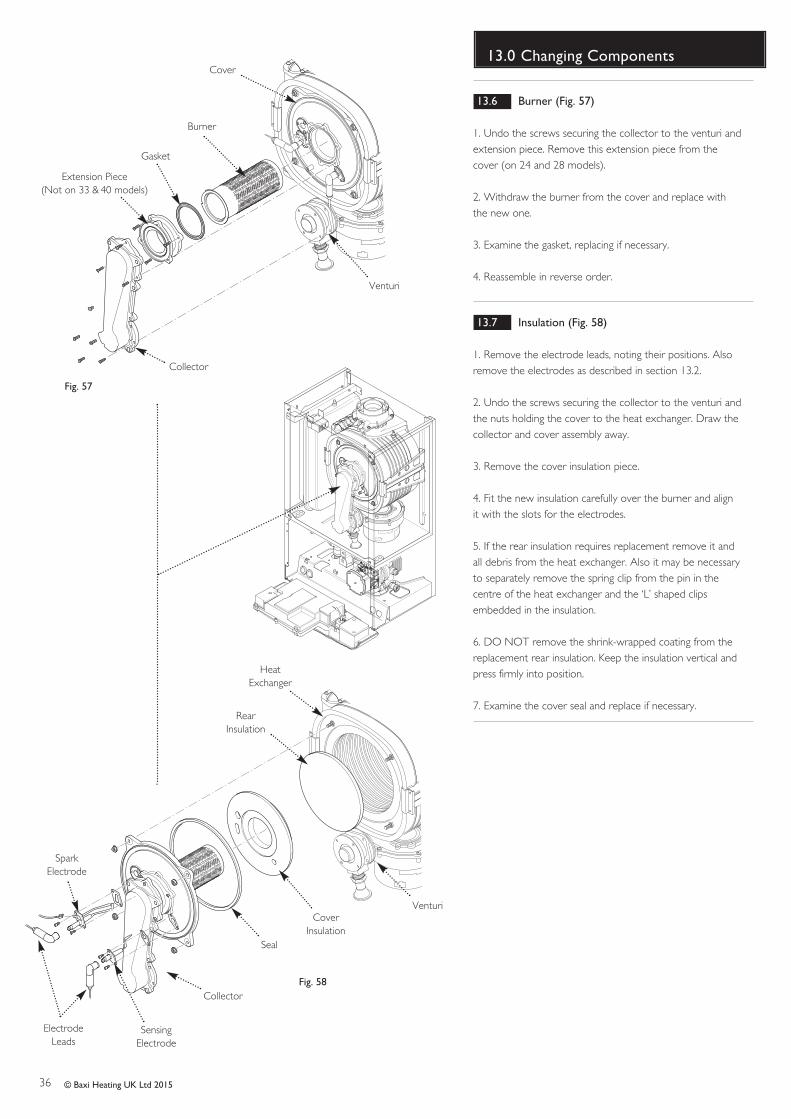
36 © Baxi Heating UK Ltd 2015
13.0 Changing Components
Fig. 57
Cover
Burner
Gasket
Extension Piece(Not on 33 & 40 models)
Collector
Venturi
HeatExchanger
RearInsulation
CoverInsulation
Seal
Collector
SparkElectrode
SensingElectrode
ElectrodeLeads
Venturi
Fig. 58
13.6 Burner (Fig. 57)
1. Undo the screws securing the collector to the venturi andextension piece. Remove this extension piece from thecover (on 24 and 28 models).
2. Withdraw the burner from the cover and replace withthe new one.
3. Examine the gasket, replacing if necessary.
4. Reassemble in reverse order.
13.7 Insulation (Fig. 58)
1. Remove the electrode leads, noting their positions. Alsoremove the electrodes as described in section 13.2.
2. Undo the screws securing the collector to the venturi andthe nuts holding the cover to the heat exchanger. Draw thecollector and cover assembly away.
3. Remove the cover insulation piece.
4. Fit the new insulation carefully over the burner and alignit with the slots for the electrodes.
5. If the rear insulation requires replacement remove it andall debris from the heat exchanger. Also it may be necessaryto separately remove the spring clip from the pin in thecentre of the heat exchanger and the ‘L’ shaped clipsembedded in the insulation.
6. DO NOT remove the shrink-wrapped coating from thereplacement rear insulation. Keep the insulation vertical andpress firmly into position.
7. Examine the cover seal and replace if necessary.
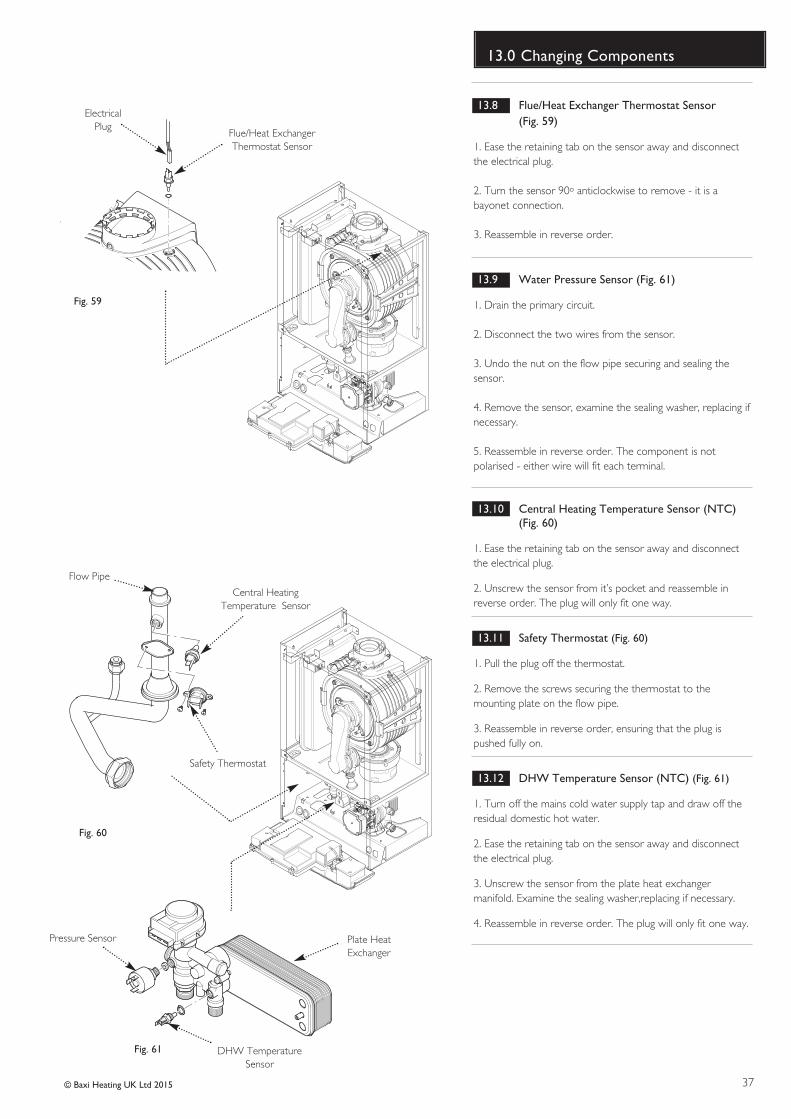
37© Baxi Heating UK Ltd 2015
13.0 Changing Components
13.8 Flue/Heat Exchanger Thermostat Sensor (Fig. 59)
1. Ease the retaining tab on the sensor away and disconnectthe electrical plug.
2. Turn the sensor 90o anticlockwise to remove - it is abayonet connection.
3. Reassemble in reverse order.
13.9 Water Pressure Sensor (Fig. 61)
1. Drain the primary circuit.
2. Disconnect the two wires from the sensor.
3. Undo the nut on the flow pipe securing and sealing thesensor.
4. Remove the sensor, examine the sealing washer, replacing ifnecessary.
5. Reassemble in reverse order. The component is notpolarised - either wire will fit each terminal.
13.10 Central Heating Temperature Sensor (NTC) (Fig. 60)
1. Ease the retaining tab on the sensor away and disconnectthe electrical plug.
2. Unscrew the sensor from it’s pocket and reassemble inreverse order. The plug will only fit one way.
13.11 Safety Thermostat (Fig. 60)
1. Pull the plug off the thermostat.
2. Remove the screws securing the thermostat to themounting plate on the flow pipe.
3. Reassemble in reverse order, ensuring that the plug ispushed fully on.
13.12 DHW Temperature Sensor (NTC) (Fig. 61)
1. Turn off the mains cold water supply tap and draw off theresidual domestic hot water.
2. Ease the retaining tab on the sensor away and disconnectthe electrical plug.
3. Unscrew the sensor from the plate heat exchangermanifold. Examine the sealing washer,replacing if necessary.
4. Reassemble in reverse order. The plug will only fit one way.
Central HeatingTemperature Sensor
Safety Thermostat
Flow Pipe
Fig. 60
DHW TemperatureSensor
Fig. 61
Plate HeatExchanger
Pressure Sensor
Flue/Heat ExchangerThermostat Sensor
ElectricalPlug
Fig. 59
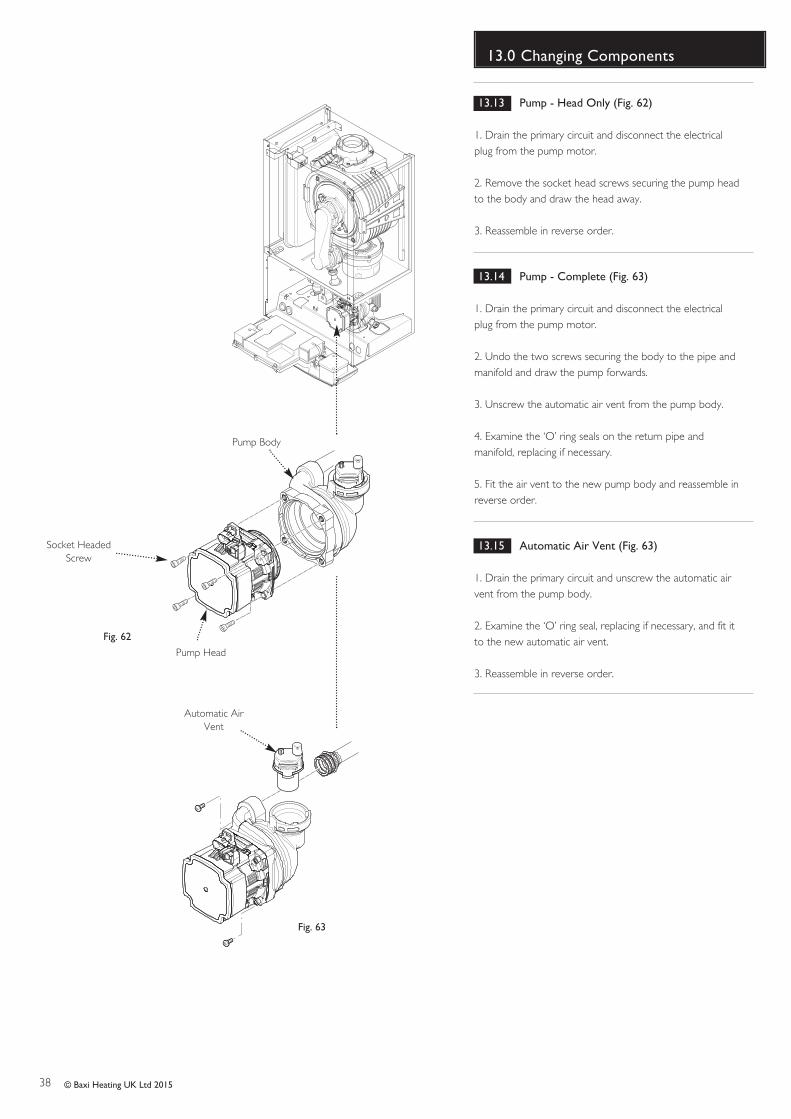
38 © Baxi Heating UK Ltd 2015
13.0 Changing Components
13.13 Pump - Head Only (Fig. 62)
1. Drain the primary circuit and disconnect the electricalplug from the pump motor.
2. Remove the socket head screws securing the pump headto the body and draw the head away.
3. Reassemble in reverse order.
13.14 Pump - Complete (Fig. 63)
1. Drain the primary circuit and disconnect the electricalplug from the pump motor.
2. Undo the two screws securing the body to the pipe andmanifold and draw the pump forwards.
3. Unscrew the automatic air vent from the pump body.
4. Examine the ‘O’ ring seals on the return pipe andmanifold, replacing if necessary.
5. Fit the air vent to the new pump body and reassemble inreverse order.
13.15 Automatic Air Vent (Fig. 63)
1. Drain the primary circuit and unscrew the automatic airvent from the pump body.
2. Examine the ‘O’ ring seal, replacing if necessary, and fit itto the new automatic air vent.
3. Reassemble in reverse order.
Socket HeadedScrew
Pump Head
Pump Body
Automatic AirVent
Fig. 62
Fig. 63
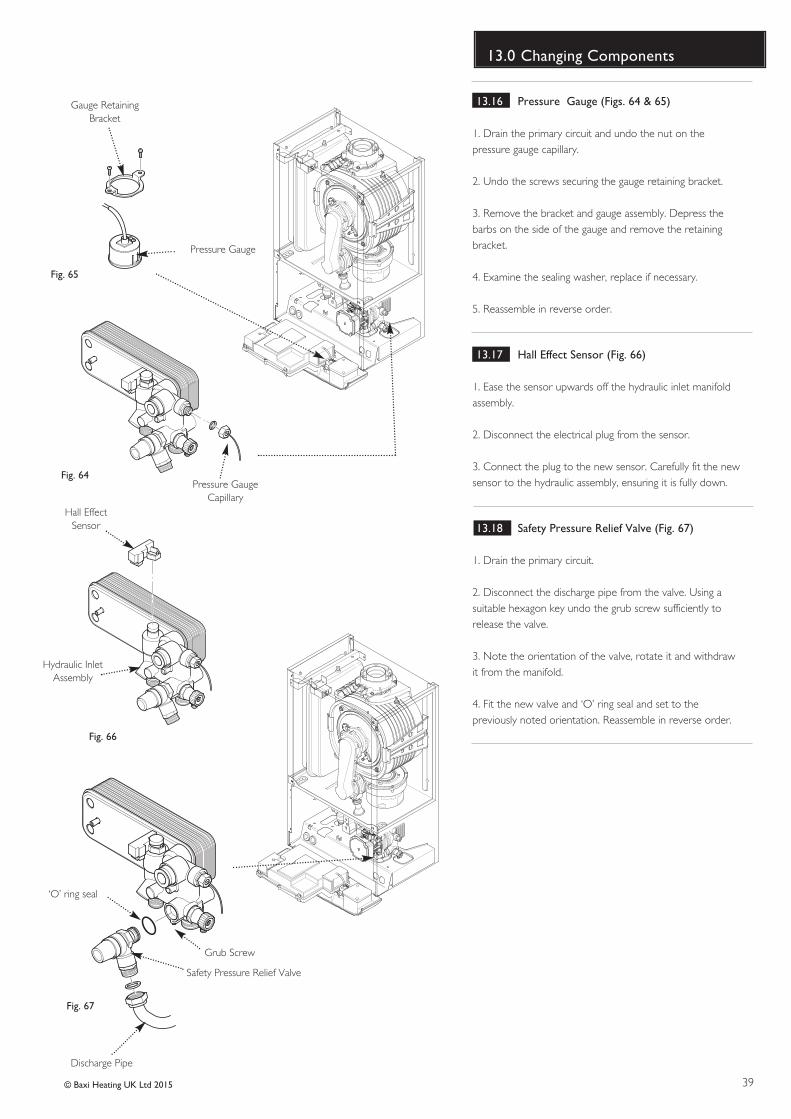
39© Baxi Heating UK Ltd 2015
13.0 Changing Components
13.16 Pressure Gauge (Figs. 64 & 65)
1. Drain the primary circuit and undo the nut on thepressure gauge capillary.
2. Undo the screws securing the gauge retaining bracket.
3. Remove the bracket and gauge assembly. Depress thebarbs on the side of the gauge and remove the retainingbracket.
4. Examine the sealing washer, replace if necessary.
5. Reassemble in reverse order.
13.17 Hall Effect Sensor (Fig. 66)
1. Ease the sensor upwards off the hydraulic inlet manifoldassembly.
2. Disconnect the electrical plug from the sensor.
3. Connect the plug to the new sensor. Carefully fit the newsensor to the hydraulic assembly, ensuring it is fully down.
13.18 Safety Pressure Relief Valve (Fig. 67)
1. Drain the primary circuit.
2. Disconnect the discharge pipe from the valve. Using asuitable hexagon key undo the grub screw sufficiently torelease the valve.
3. Note the orientation of the valve, rotate it and withdrawit from the manifold.
4. Fit the new valve and ‘O’ ring seal and set to thepreviously noted orientation. Reassemble in reverse order.
Pressure Gauge
Pressure GaugeCapillary
Gauge RetainingBracket
Fig. 64
Fig. 65
Safety Pressure Relief Valve
Grub Screw
‘O’ ring seal
Discharge Pipe
Fig. 67
Hall EffectSensor
Hydraulic InletAssembly
Fig. 66
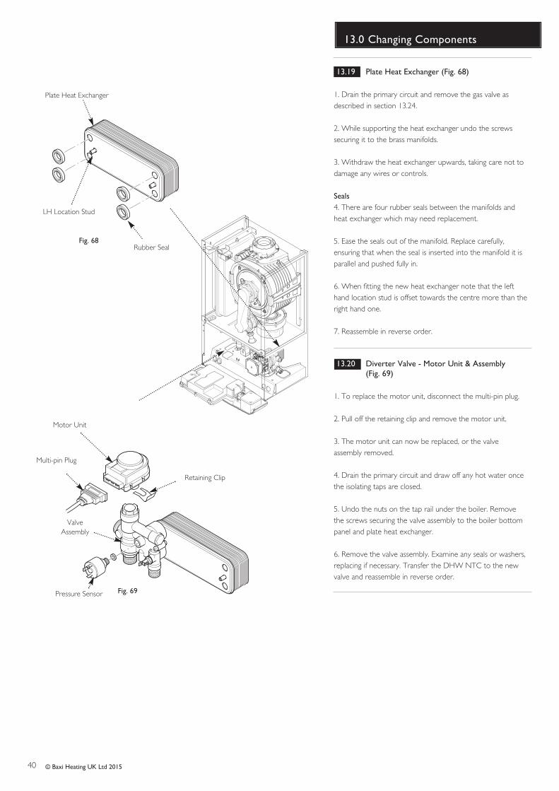
40 © Baxi Heating UK Ltd 2015
13.0 Changing Components
13.19 Plate Heat Exchanger (Fig. 68)
1. Drain the primary circuit and remove the gas valve asdescribed in section 13.24.
2. While supporting the heat exchanger undo the screwssecuring it to the brass manifolds.
3. Withdraw the heat exchanger upwards, taking care not todamage any wires or controls.
Seals4. There are four rubber seals between the manifolds andheat exchanger which may need replacement.
5. Ease the seals out of the manifold. Replace carefully,ensuring that when the seal is inserted into the manifold it isparallel and pushed fully in.
6. When fitting the new heat exchanger note that the lefthand location stud is offset towards the centre more than theright hand one.
7. Reassemble in reverse order.
13.20 Diverter Valve - Motor Unit & Assembly (Fig. 69)
1. To replace the motor unit, disconnect the multi-pin plug.
2. Pull off the retaining clip and remove the motor unit.
3. The motor unit can now be replaced, or the valveassembly removed.
4. Drain the primary circuit and draw off any hot water oncethe isolating taps are closed.
5. Undo the nuts on the tap rail under the boiler. Removethe screws securing the valve assembly to the boiler bottompanel and plate heat exchanger.
6. Remove the valve assembly. Examine any seals or washers,replacing if necessary. Transfer the DHW NTC to the newvalve and reassemble in reverse order.
Plate Heat Exchanger
Rubber SealFig. 68
Motor Unit
Multi-pin Plug
Retaining Clip
ValveAssembly
Fig. 69
LH Location Stud
Pressure Sensor
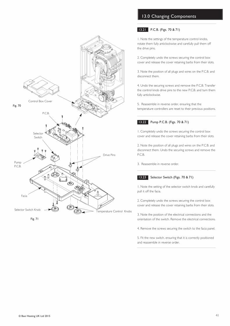
41© Baxi Heating UK Ltd 2015
13.0 Changing Components
13.21 P.C.B. (Figs. 70 & 71)
1. Note the settings of the temperature control knobs,rotate them fully anticlockwise and carefully pull them offthe drive pins.
2. Completely undo the screws securing the control boxcover and release the cover retaining barbs from their slots.
3. Note the position of all plugs and wires on the P.C.B. anddisconnect them.
4. Undo the securing screws and remove the P.C.B. Transferthe control knob drive pins to the new P.C.B. and turn themfully anticlockwise.
5. Reassemble in reverse order, ensuring that thetemperature controllers are reset to their previous positions.
13.22 Pump P.C.B. (Figs. 70 & 71)
1. Completely undo the screws securing the control boxcover and release the cover retaining barbs from their slots.
2. Note the position of all plugs and wires on the P.C.B. anddisconnect them. Undo the securing screws and remove theP.C.B.
3. Reassemble in reverse order.
13.23 Selector Switch (Figs. 70 & 71)
1. Note the setting of the selector switch knob and carefullypull it off the facia.
2. Completely undo the screws securing the control boxcover and release the cover retaining barbs from their slots.
3. Note the position of the electrical connections and theorientation of the switch. Remove the electrical connections.
4. Remove the screws securing the switch to the facia panel.
5. Fit the new switch, ensuring that it is correctly positionedand reassemble in reverse order.
Control Box Cover
P.C.B.
SelectorSwitch
Facia
Selector Switch Knob Temperature Control Knobs
Fig. 70
Fig. 71
Drive Pins
PumpP.C.B.
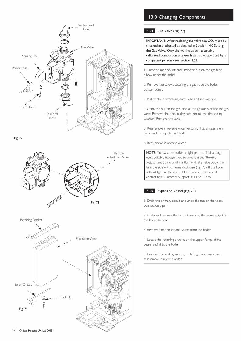
42 © Baxi Heating UK Ltd 2015
13.0 Changing Components
13.24 Gas Valve (Fig. 72)
IMPORTANT: After replacing the valve the CO2 must bechecked and adjusted as detailed in Section 14.0 Settingthe Gas Valve. Only change the valve if a suitablecalibrated combustion analyser is available, operated by acompetent person - see section 12.1.
1. Turn the gas cock off and undo the nut on the gas feedelbow under the boiler.
2. Remove the screws securing the gas valve the boilerbottom panel.
3. Pull off the power lead, earth lead and sensing pipe.
4. Undo the nut on the gas pipe at the gas/air inlet and the gasvalve. Remove the pipe, taking care not to lose the sealingwashers. Remove the valve.
5. Reassemble in reverse order, ensuring that all seals are inplace and the injector is fitted. 6. Reassemble in reverse order.
NOTE: To assist the boiler to light prior to final setting,use a suitable hexagon key to wind out the ThrottleAdjustment Screw until it is flush with the valve body, thenturn the screw 4 full turns clockwise (Fig. 73). If the boilerwill not light, or the correct CO2 cannot be achievedcontact Baxi Customer Support 0344 871 1525.
13.25 Expansion Vessel (Fig. 74)
1. Drain the primary circuit and undo the nut on the vesselconnection pipe.
2. Undo and remove the locknut securing the vessel spigot tothe boiler air box.
3. Remove the bracket and vessel from the boiler.
4. Locate the retaining bracket on the upper flange of thevessel and fit to the boiler.
5. Examine the sealing washer, replacing if necessary, andreassemble in reverse order.
Gas Valve
Earth Lead
Gas FeedElbow
Fig. 72
Power Lead
Expansion Vessel
Boiler Chassis
Lock Nut
Fig. 74
Retaining Bracket
Sensing Pipe
Venturi InletPipe
Fig. 73
Throttle Adjustment Screw
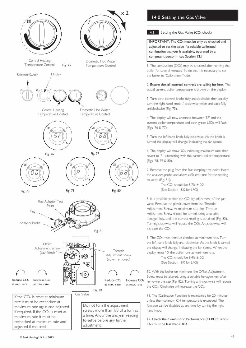
43© Baxi Heating UK Ltd 2015
14.0 Setting the Gas Valve
Selector Switch Display
bar
0
1
2
3
4
Central Heating Temperature Control
Domestic Hot Water Temperature Control
Fig. 76 Fig. 77
Fig. 78 Fig. 79 Fig. 80
Central Heating Temperature Control
Domestic Hot Water Temperature ControlFig. 75
x 2
Fig. 81
ThrottleAdjustment Screw(cover removed)
OffsetAdjustment Screw
(cap fitted)
Gas ValveFig. 82
Flue Adaptor TestPoint
Plug
Analyser Probe
If the CO2 is reset at minimumrate it must be rechecked atmaximum rate again and adjustedif required. If the CO2 is reset atmaximum rate it must berechecked at minimum rate andadjusted if required.
Do not turn the adjustmentscrews more than 1/8 of a turn ata time. Allow the analyser readingto settle before any furtheradjustment
Reduce CO2
at min. rateIncrease CO2
at min. rateReduce CO2
at max. rateIncrease CO2
at max. rate
14.1 Setting the Gas Valve (CO2 check)
IMPORTANT: The CO2 must be only be checked andadjusted to set the valve if a suitable calibratedcombustion analyser is available, operated by acompetent person - see Section 12.1
1. The combustion (CO2) may be checked after running theboiler for several minutes. To do this it is necessary to setthe boiler to ‘Calibration Mode’.
2. Ensure that all external controls are calling for heat. Theactual current boiler temperature is shown on the display.
3. Turn both control knobs fully anticlockwise, then quicklyturn the right hand knob 1/4 clockwise twice and back fullyanticlockwise (Fig. 75).
4. The display will now alternate between ‘SF’ and thecurrent boiler temperature and both green LEDs will flash(Figs. 76 & 77).
5. Turn the left hand knob fully clockwise. As the knob isturned the display will change, indicating the fan speed.
6. The display will show ‘00’, indicating maximum rate, thenrevert to ‘P ‘ alternating with the current boiler temperature(Figs. 78, 79 & 80).
7. Remove the plug from the flue sampling test point. Insertthe analyser probe and allow sufficient time for the readingto settle (Fig. 81).
The CO2 should be 8.7% ± 0.2(See Section 18.0 for LPG)
8. It is possible to alter the CO2 by adjustment of the gasvalve. Remove the plastic cover from the ThrottleAdjustment Screw. At maximum rate the ThrottleAdjustment Screw should be turned, using a suitablehexagon key, until the correct reading is obtained (Fig. 82). Turning clockwise will reduce the CO2. Anticlockwise willincrease th e CO2.
9. The CO2 must then be checked at minimum rate. Turnthe left hand knob fully anti-clockwise. As the knob is turnedthe display will change, indicating the fan speed. When thedisplay reads ‘ 0’ the boiler runs at minimum rate.
The CO2 should be 8.4% ± 0.2(See Section 18.0 for LPG)
10. With the boiler on minimum, the Offset AdjustmentScrew must be altered, using a suitable hexagon key, afterremoving the cap (Fig. 82). Turning anti-clockwise will reducethe CO2. Clockwise will increase th e CO2.
11. The ‘Calibration Function’ is maintained for 20 minutesunless the maximum CH temperature is exceeded. Thefunction can be disabled at any time by turning the righthand knob.
12. Check the Combustion Performance (CO/CO2 ratio).This must be less than 0.004.
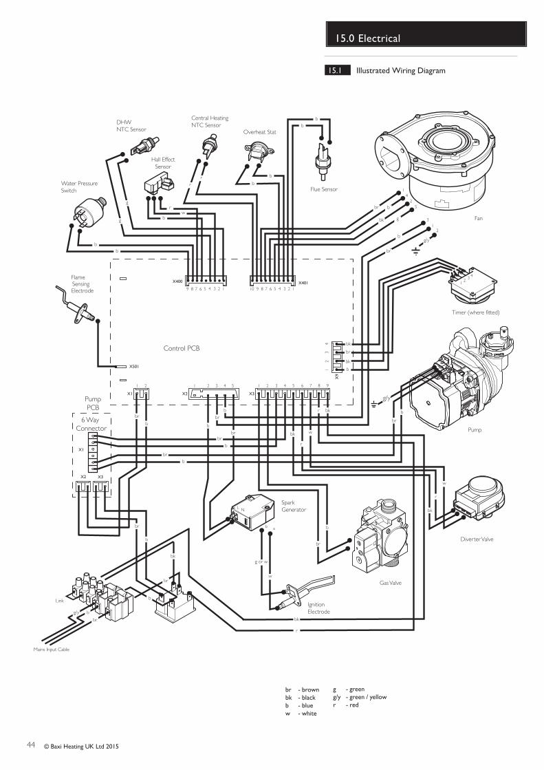
44 © Baxi Heating UK Ltd 2015
15.0 Electrical
- brown- black- blue- white
brbkbw
- green- green / yellow- red
gg/yr
Control PCB
X2 X3
X9
X501
1 21 2 33 44 55 6 7 8 9
X1
1 2
DHW NTC Sensor
Central Heating NTC Sensor
Fan
Gas Valve
Overheat Stat
FlameSensingElectrode
Pump
Flue Sensor
X400 X401
g
g
bb
rr
b
b
bb
bbr
bk g
b
br
g/y
b
br
b
br
br
b
b
br
br
b
b
br
r bk
r
bk
Water PressureSwitch
SparkGenerator
IgnitionElectrode
9 8 7 6 5 4 3 2 1 910 8 7 6 5 4 3 2 1
Hall EffectSensor
rw
b
w
r
bk
bk
r
w
Diverter Valve
12 34
12
34 bk
br
bk
b
NL
w
g or w
1425
312
ab
Link
bk
bg/y
br
Mains Input Cable
br
b
b
br
PumpPCB
Timer (where fitted)
X1
X2 X3
g/y
6 Way Connector
brb
15.1 Illustrated Wiring Diagram
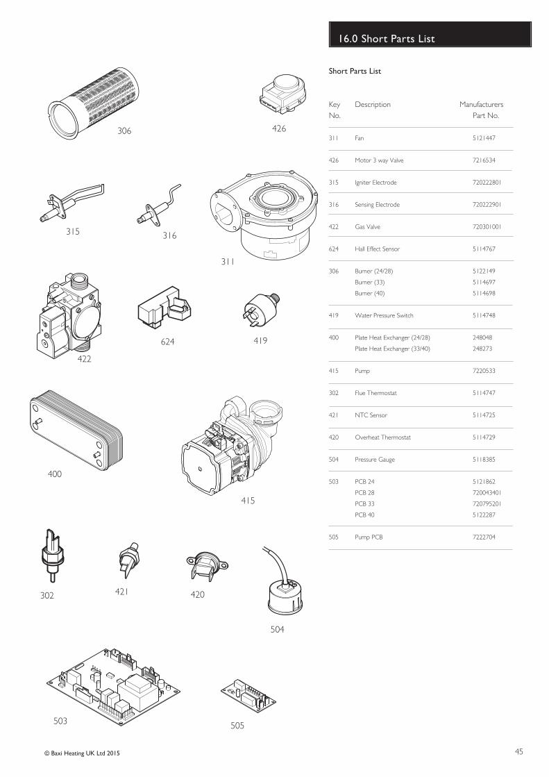
45© Baxi Heating UK Ltd 2015
16.0 Short Parts List
Short Parts List
Key Description ManufacturersNo. Part No.
311 Fan 5121447
426 Motor 3 way Valve 7216534
315 Igniter Electrode 720222801
316 Sensing Electrode 720222901
422 Gas Valve 720301001
624 Hall Effect Sensor 5114767
306 Burner (24/28) 5122149
Burner (33) 5114697
Burner (40) 5114698
419 Water Pressure Switch 5114748
400 Plate Heat Exchanger (24/28) 248048
Plate Heat Exchanger (33/40) 248273
415 Pump 7220533
302 Flue Thermostat 5114747
421 NTC Sensor 5114725
420 Overheat Thermostat 5114729
504 Pressure Gauge 5118385
503 PCB 24 5121862
PCB 28 720043401
PCB 33 720795201
PCB 40 5122287
505 Pump PCB 7222704
306 426
315 316
311
422
624 419
400
415
302 421 420
503
504
505
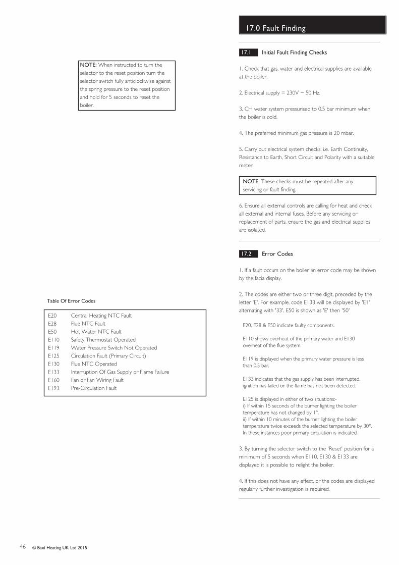
46 © Baxi Heating UK Ltd 2015
17.0 Fault Finding
NOTE: When instructed to turn theselector to the reset position turn theselector switch fully anticlockwise againstthe spring pressure to the reset positionand hold for 5 seconds to reset theboiler.
17.1 Initial Fault Finding Checks
1. Check that gas, water and electrical supplies are availableat the boiler.
2. Electrical supply = 230V ~ 50 Hz.
3. CH water system pressurised to 0.5 bar minimum whenthe boiler is cold.
4. The preferred minimum gas pressure is 20 mbar.
5. Carry out electrical system checks, i.e. Earth Continuity,Resistance to Earth, Short Circuit and Polarity with a suitablemeter.
NOTE: These checks must be repeated after anyservicing or fault finding.
6. Ensure all external controls are calling for heat and checkall external and internal fuses. Before any servicing orreplacement of parts, ensure the gas and electrical suppliesare isolated.
17.2 Error Codes
1. If a fault occurs on the boiler an error code may be shownby the facia display.
2. The codes are either two or three digit, preceded by theletter 'E'. For example, code E133 will be displayed by 'E1'alternating with '33'. E50 is shown as 'E' then '50'
E20, E28 & E50 indicate faulty components.
E110 shows overheat of the primary water and E130overheat of the flue system.
E119 is displayed when the primary water pressure is lessthan 0.5 bar.
E133 indicates that the gas supply has been interrupted,ignition has failed or the flame has not been detected.
E125 is displayed in either of two situations:-i) If within 15 seconds of the burner lighting the boilertemperature has not changed by 1°.ii) If within 10 minutes of the burner lighting the boilertemperature twice exceeds the selected temperature by 30°.In these instances poor primary circulation is indicated.
3. By turning the selector switch to the 'Reset' position for aminimum of 5 seconds when E110, E130 & E133 aredisplayed it is possible to relight the boiler.
4. If this does not have any effect, or the codes are displayedregularly further investigation is required.
Central Heating NTC FaultFlue NTC FaultHot Water NTC Fault Safety Thermostat OperatedWater Pressure Switch Not OperatedCirculation Fault (Primary Circuit)Flue NTC OperatedInterruption Of Gas Supply or Flame FailureFan or Fan Wiring FaultPre-Circulation Fault
E20E28E50E110E119E125E130E133E160E193
Table Of Error Codes
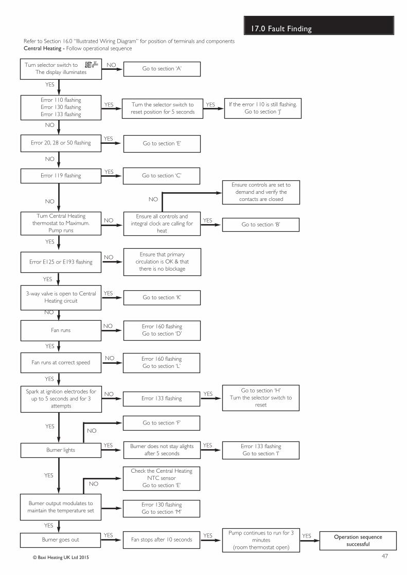
47© Baxi Heating UK Ltd 2015
17.0 Fault FindingRefer to Section 16.0 “Illustrated Wiring Diagram” for position of terminals and componentsCentral Heating - Follow operational sequence
Turn selector switch to The display illuminates
Error 20, 28 or 50 flashing
Error 119 flashing
Burner lights
Error 110 flashingError 130 flashingError 133 flashing
Turn Central Heatingthermostat to Maximum.
Pump runs
Fan runs
Spark at ignition electrodes forup to 5 seconds and for 3
attempts
3-way valve is open to CentralHeating circuit
Go to section ‘A’
Go to section ‘E’
Ensure all controls andintegral clock are calling for
heat
Go to section ‘K’
Go to section ‘B’
Error 160 flashingGo to section ‘D’
Error 133 flashing
Burner does not stay alightsafter 5 seconds
Error 133 flashingGo to section ‘I’
Operation sequencesuccessful
If the error 110 is still flashing.Go to section ‘J’
Fan runs at correct speed
YES
YES
NO
NO
NO
YES
YES
YES
YES
YES
YES YES
YES
NO
YES YES
YES
YES
NO
NO
NO
NO
NO
Burner output modulates tomaintain the temperature set
Burner goes out
Go to section ‘C’
Ensure controls are set todemand and verify the
contacts are closed
Error 160 flashingGo to section ‘L’
YESGo to section ‘H’
Turn the selector switch toreset
Go to section ‘F’
Error 130 flashingGo to section ‘M’
YES
Check the Central HeatingNTC sensor
Go to section ‘E’
Fan stops after 10 secondsPump continues to run for 3
minutes (room thermostat open)
NO
NO
YES
NO
YES YES
Turn the selector switch toreset position for 5 seconds
NO
Error E125 or E193 flashingEnsure that primary
circulation is OK & thatthere is no blockage
YES
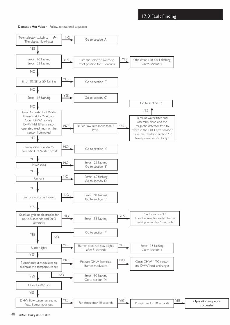
48 © Baxi Heating UK Ltd 2015
17.0 Fault Finding
Turn selector switch to The display illuminates
Error 20, 28 or 50 flashing
Error 119 flashing
Burner lights
Error 110 flashingError 133 flashing
Turn Domestic Hot Waterthermostat to Maximum.
Open DHW tap fully.DHW Hall Effect sensor
operated (red neon on thesensor illuminated
Fan runs
Spark at ignition electrodes forup to 5 seconds and for 3
attempts
3-way valve is open toDomestic Hot Water circuit
Go to section ‘A’
Go to section ‘E’
Is mains water filter andassembly clean and the
magnetic detector free tomove in the Hall Effect sensor ?Have the checks in section ‘G’
been passed satisfactorily ?
Go to section ‘K’
Go to section ‘B’
Error 160 flashingGo to section ‘D’
Error 133 flashing
Burner does not stay alightsafter 5 seconds
Error 133 flashingGo to section ‘I’
Operation sequencesuccessful
Turn the selector switch toreset position for 5 seconds
If the error 110 is still flashing.Go to section ‘J’
Fan runs at correct speed
YES
YES
NO
NO
NO
YES
YES
YES
YES
YES
YES YES
YES
NO
YES YES
YES
YES
NO
NO
NO
NO
NO
Burner output modulates tomaintain the temperature set
DHW flow sensor senses noflow. Burner goes out
Go to section ‘C’
DHW flow rate more than 2l/min
Error 160 flashingGo to section ‘L’
YESGo to section ‘H’
Turn the selector switch to thereset position for 5 seconds
Go to section ‘F’
Error 130 flashingGo to section ‘M’
YES
Reduce DHW flow rateBurner modulates
Fan stops after 10 seconds Pump runs for 30 seconds
NO
YES
NO
YES YES
Domestic Hot Water - Follow operational sequence
Pump runs
YES
Error 125 flashingGo to section ‘B’
NO
Close DHW tap
YES NO
YES
Clean DHW NTC sensorand DHW heat exchanger
NO
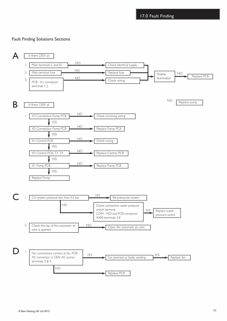
49© Baxi Heating UK Ltd 2015
17.0 Fault Finding
Fault Finding Solutions Sections
Is there 230V at:
Is there 230V at:
Main terminals L and N Check electrical supply1. NO
Main terminal fuse Replace fuseReplace PCB
Displayilluminated
2. NO
PCB - X1 connectorterminals 1,2
Check wiring3. NO
NO
A
X3 Connection Pump PCB
Replace pump
1. NO
YES
B
CH system pressure less than 0.5 bar Re-pressurise system1. YES
Check the tap of the automatic airvent is opened
Open the automatic air vent2. NO
C
1.
NO
YESFan connections correct at fan. PCB -X2 connector, is 230V AC acrossterminals 3 & 4
Fan jammed or faulty winding
Replace PCB
Replace fanYES
D
Check incoming wiring
NO
NO
Replace waterpressure switch
Check connection water pressureswitch terminalCOM - NO and PCB connectorX400 terminals 3,4
YES
X2 Connection Pump PCBNO
Replace Pump PCB
YES
X1 Control PCBNO
Check wiring
YES
X3 Control PCB, T3, T4NO
Replace Control PCB
YES
X1 Pump PCBNO
Replace Pump PCB
YES
Replace Pump
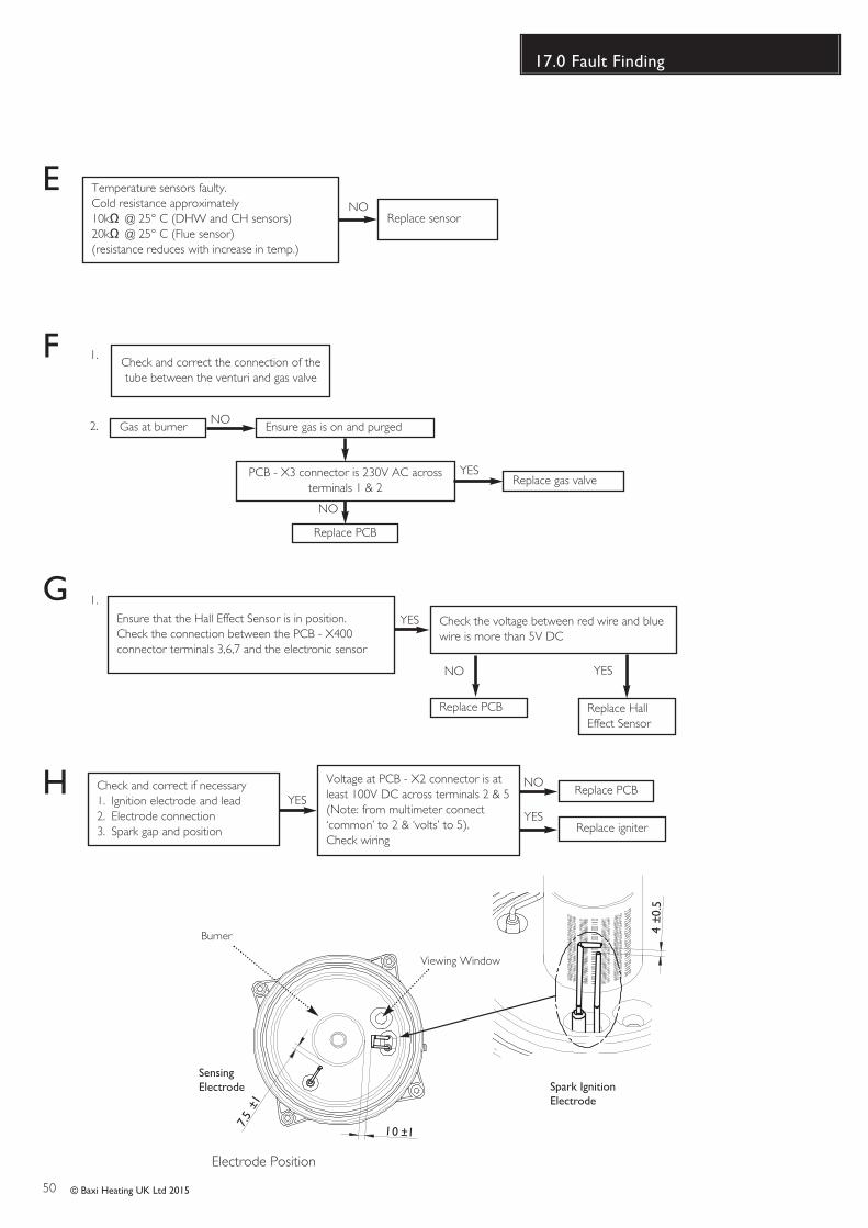
50 © Baxi Heating UK Ltd 2015
17.0 Fault Finding
Temperature sensors faulty.Cold resistance approximately10k� @ 25° C (DHW and CH sensors)20k� @ 25° C (Flue sensor)(resistance reduces with increase in temp.)
NO
EReplace sensor
Gas at burner Ensure gas is on and purged
Replace PCB
Replace gas valvePCB - X3 connector is 230V AC across
terminals 1 & 2YES
NO
NO
F
Replace PCB
G
Check and correct if necessary1. Ignition electrode and lead2. Electrode connection3. Spark gap and position
Voltage at PCB - X2 connector is atleast 100V DC across terminals 2 & 5(Note: from multimeter connect‘common’ to 2 & ‘volts’ to 5). Check wiring
YES
NO
Replace igniterYES
H
YES
1.
Ensure that the Hall Effect Sensor is in position.Check the connection between the PCB - X400connector terminals 3,6,7 and the electronic sensor
Check the voltage between red wire and bluewire is more than 5V DC
NO
Replace PCB
Check and correct the connection of thetube between the venturi and gas valve
Replace HallEffect Sensor
YES
1.
2.
7.5
±1
4±0
.5
10 ±1
Spark Ignition Electrode
Sensing Electrode
Electrode Position
Viewing Window
Burner
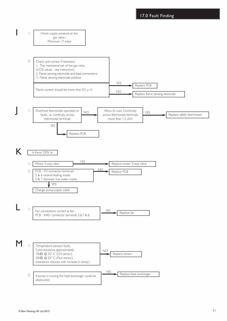
51© Baxi Heating UK Ltd 2015
17.0 Fault Finding
Check and correct if necessary1. The mechanical set of the gas valve(CO2 values - see instruction)2. Flame sensing electrode and lead connections3. Flame sensing electrode position
Flame current should be more than 0.5 � AReplace PCB
Replace PCB
YES
YES
Replace flame sensing electrodeNO
I
K
Replace safety thermostatYESNOOverheat thermostat operated or
faulty, i.e. continuity acrossthermostat terminals
Allow to cool. Continuityacross thermostat terminals
more than 1.5 ohm
J
L
M
Is there 230V at:
Motor 3-way valve Replace motor 3-way valve1. YES
PCB - X3 connector terminals 5 & 6 central heating mode 5 & 7 domestic hot water mode
Replace PCB2. NO
Change pump supply cable
YES
Fan connections correct at fan.PCB - X401 connector terminals 5,6,7 & 8
1. YESReplace fan
Temperature sensors faulty.Cold resistance approximately10k� @ 25° C (CH sensor)20k� @ 25° C (Flue sensor)(resistance reduces with increase in temp.)
NOReplace sensor
YESIf pump is running the heat exchanger could beobstructed
Replace heat exchanger
1.
2.
1.
2.
1.
Check supply pressure at the gas valve:-
Minimum 17 mbar
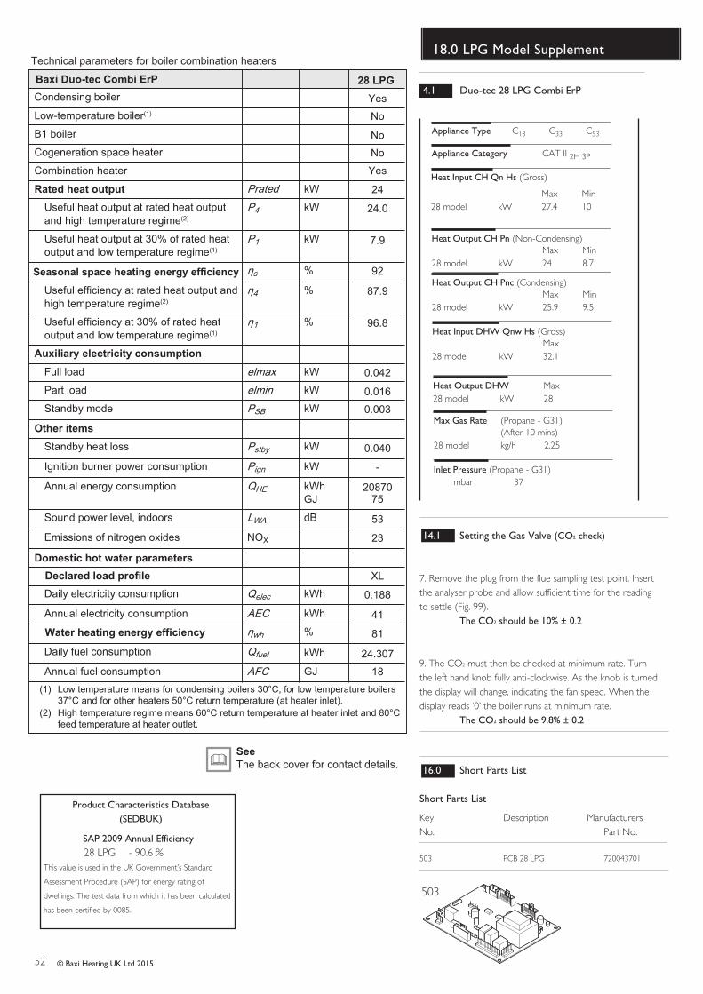
52 © Baxi Heating UK Ltd 2015
18.0 LPG Model Supplement
Inlet Pressure (Propane - G31)mbar 37
Heat Output CH Pn (Non-Condensing)Max Min
28 model kW 24 8.7
Appliance Category CAT II 2H 3P
Appliance Type C13 C33 C53
Heat Output CH Pnc (Condensing)Max Min
28 model kW 25.9 9.5
Heat Output DHW Max28 model kW 28
Max Gas Rate (Propane - G31)(After 10 mins)
28 model kg/h 2.25
Heat Input CH Qn Hs (Gross)
Max Min28 model kW 27.4 10
Heat Input DHW Qnw Hs (Gross)Max
28 model kW 32.1
14.1 Setting the Gas Valve (CO2 check)
7. Remove the plug from the flue sampling test point. Insertthe analyser probe and allow sufficient time for the readingto settle (Fig. 99).
The CO2 should be 10% ± 0.2
9. The CO2 must then be checked at minimum rate. Turnthe left hand knob fully anti-clockwise. As the knob is turnedthe display will change, indicating the fan speed. When thedisplay reads ‘0’ the boiler runs at minimum rate.
The CO2 should be 9.8% ± 0.2
4.1 Duo-tec 28 LPG Combi ErP
503
16.0 Short Parts List
Short Parts List
Key G.C. Description ManufacturersNo. No. Part No.
503 PCB 28 LPG 720043701
Technical parameters for boiler combination heaters
Condensing boiler
28 LPGBaxi Duo-tec Combi ErP
Rated heat output
Seasonal space heating energy efficiency
Auxiliary electricity consumption
Other items
Low-temperature boiler(1)
B1 boiler
Cogeneration space heater
Combination heater
Prated kW
Useful heat output at rated heat output and high temperature regime(2)
P4 kW
Useful heat output at 30% of rated heat output and low temperature regime(1)
P1 kW
s %
Useful efficiency at rated heat output and high temperature regime(2)
4 %
Useful efficiency at 30% of rated heat output and low temperature regime(1)
1 %
Full load elmax kW
Part load elmin kW
Standby mode PSB kW
Standby heat loss Pstby kW
Ignition burner power consumption Pign kW
Annual energy consumption QHE kWhGJ
Sound power level, indoors LWA dB
Emissions of nitrogen oxides NOX
Daily electricity consumption
Domestic hot water parameters
Declared load profile
Water heating energy efficiency
Qelec kWh
Annual electricity consumption AEC kWh
wh %
Daily fuel consumption Qfuel kWh
Annual fuel consumption AFC GJ
(1) Low temperature means for condensing boilers 30°C, for low temperature boilers 37°C and for other heaters 50°C return temperature (at heater inlet).
(2) High temperature regime means 60°C return temperature at heater inlet and 80°C feed temperature at heater outlet.
SeeThe back cover for contact details.
Yes
No
Yes
No
No
24
24.0
7.9
92
87.9
96.8
0.042
0.016
0.003
0.040
-
2087075
53
23
XL
0.188
41
81
24.307
18
SAP 2009 Annual Efficiency28 LPG - 90.6 %
This value is used in the UK Government’s Standard
Assessment Procedure (SAP) for energy rating of
dwellings. The test data from which it has been calculated
has been certified by 0085.
Product Characteristics Database(SEDBUK)

53© Baxi Heating UK Ltd 2015
19.0 Notes
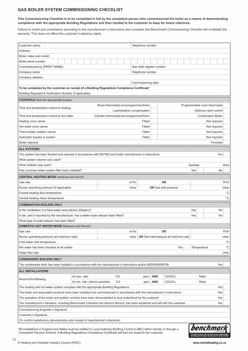
54
*All installations in England and Wales must be to Local Authority Building Control (LABC) either directly or through aCompetent Persons Scheme. A Building Regulations Compliance will then be issued to the customer.
www.centralheating.co.uk© Heating and Hotwater Industry Council (HHIC)
This Commissioning Checklist is to be completed in full by the competent person who commissioned the boiler as a means of demonstrating compliance with the appropriate Building Regulations and then handed to the customer to keep for future reference.
Failure to install and commission according to the manufacturer’s instructions and complete this Benchmark Commissioning Checklist will invalidate the warranty. This does not affect the customer’s statutory rights.
GAS BOILER SYSTEM COMMISSIONING CHECKLIST
Customer name: Telephone number:
Address:
Boiler make and model:
Boiler serial number:
Commissioned by (PRINT NAME): Gas Safe register number:
Company name: Telephone number:
Company address:
Commissioning date:
CONTROLS (tick the appropriate boxes)
Time and temperature control to heatingRoom thermostat and programmer/timer Programmable room thermostat
Load/weather compensation Optimum start control
Time and temperature control to hot water Cylinder thermostat and programmer/timer Combination Boiler
Heating zone valves Fitted Not required
Hot water zone valves Fitted Not required
Thermostatic radiator valves Fitted Not required
Automatic bypass to system Fitted Not required
Boiler interlock Provided
ALL SYSTEMS
’s instructions Yes
What system cleaner was used?
What inhibitor was used? Quantity litres
Yes No
CENTRAL HEATING MODE measure and record:
Gas rate m³/hr OR ft³/hr
Burner operating pressure (if applicable) mbar OR Gas inlet pressure mbar
°C
Central heating return temperature °C
COMBINATION BOILERS ONLY
Is the installation in a hard water area (above 200ppm)? Yes No
Yes No
DOMESTIC HOT WATER MODE Measure and Record:
Gas rate m³/hr OR ft³/hr
Burner operating pressure (at maximum rate) mbar OR Gas inlet pressure at maximum rate mbar
Cold water inlet temperature °C
Hot water has been checked at all outlets Yes Temperature °C
I/min
CONDENSING BOILERS ONLY
The condensate drain has been installed in accordance with the manufacturer’s instructions and/or BS5546/BS6798 Yes
ALL INSTALLATIONS
Record the following:At max. rate: CO ppm AND CO/CO² Ratio
At min. rate: (where possible) CO ppm AND CO/CO² Ratio
The heating and hot water system complies with the appropriate Building Regulations Yes
The boiler and associated products have been installed and commissioned in accordance with the manufacturer’s instructions Yes
The operation of the boiler and system controls have been demonstrated to and understood by the customer Yes
The manufacturer’s literature, including Benchmark Checklist and Service Record, has been explained and left with the customer Yes
Commissioning Engineer’s Signature
Customer’s Signature
www.centralheating.co.uk
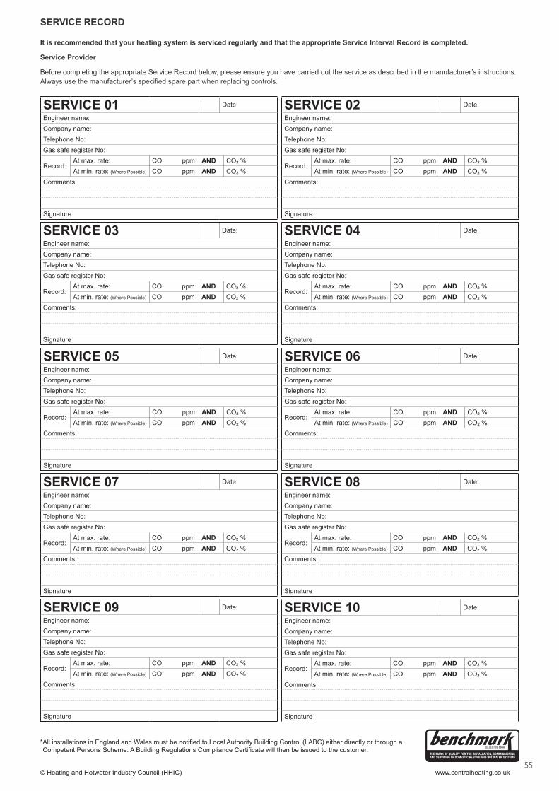
55www.centralheating.co.uk
It is recommended that your heating system is serviced regularly and that the appropriate Service Interval Record is completed.
Service Provider
Before completing the appropriate Service Record below, please ensure you have carried out the service as described in the manufacturer’s instructions.
SERVICE RECORD
SERVICE 01 Date:
Engineer name:
Company name:
Telephone No:
Gas safe register No:
Record:At max. rate: CO ppm AND CO² %
At min. rate: (Where Possible) CO ppm AND CO² %
Comments:
Signature
SERVICE 02 Date:
Engineer name:
Company name:
Telephone No:
Gas safe register No:
Record:At max. rate: CO ppm AND CO² %
At min. rate: (Where Possible) CO ppm AND CO² %
Comments:
Signature
SERVICE 03 Date:
Engineer name:
Company name:
Telephone No:
Gas safe register No:
Record:At max. rate: CO ppm AND CO² %
At min. rate: (Where Possible) CO ppm AND CO² %
Comments:
Signature
SERVICE 04 Date:
Engineer name:
Company name:
Telephone No:
Gas safe register No:
Record:At max. rate: CO ppm AND CO² %
At min. rate: (Where Possible) CO ppm AND CO² %
Comments:
Signature
SERVICE 05 Date:
Engineer name:
Company name:
Telephone No:
Gas safe register No:
Record:At max. rate: CO ppm AND CO² %
At min. rate: (Where Possible) CO ppm AND CO² %
Comments:
Signature
SERVICE 06 Date:
Engineer name:
Company name:
Telephone No:
Gas safe register No:
Record:At max. rate: CO ppm AND CO² %
At min. rate: (Where Possible) CO ppm AND CO² %
Comments:
Signature
SERVICE 07 Date:
Engineer name:
Company name:
Telephone No:
Gas safe register No:
Record:At max. rate: CO ppm AND CO² %
At min. rate: (Where Possible) CO ppm AND CO² %
Comments:
Signature
SERVICE 08 Date:
Engineer name:
Company name:
Telephone No:
Gas safe register No:
Record:At max. rate: CO ppm AND CO² %
At min. rate: (Where Possible) CO ppm AND CO² %
Comments:
Signature
SERVICE 09 Date:
Engineer name:
Company name:
Telephone No:
Gas safe register No:
Record:At max. rate: CO ppm AND CO² %
At min. rate: (Where Possible) CO ppm AND CO² %
Comments:
Signature
SERVICE 10 Date:
Engineer name:
Company name:
Telephone No:
Gas safe register No:
Record:At max. rate: CO ppm AND CO² %
At min. rate: (Where Possible) CO ppm AND CO² %
Comments:
Signature
*All installations in England and Wales must be to Local Authority Building Control (LABC) either directly or through aCompetent Persons Scheme. A Building Regulations Compliance will then be issued to the customer.
© Heating and Hotwater Industry Council (HHIC)
7219665 - 02 (10/15)
0086
Baxi Customer Support0344 871 1525
Opening hoursMonday - Friday, 8.00am-6.00pm
Weekends and Bank Holidays, 8.30am-2.00pm
Please note calls may be recorded for training and monitoring purposes
baxi.co.uk
Register now to activate your warranty:
www.baxi.co.uk/registration
For the warranty to be maintained, please make sure...
Benchmark checklist is completedWarranty is registered with BaxiThe boiler has an annual service
1
2
3
For full terms and conditions, visit www.baxi.co.uk/terms. Failure to adhere toterms and conditions will void your manufacturer’s warranty.
BaxiBrooks House,Coventry Road,Warwick, CV34 4LL
Please ensure the boiler is installed in accordance with these installationinstructions and that you adhere to the Building Regulations.
e&oeAll descriptions and illustrations provided in this document have beencarefully prepared but we reserve the right to make changes andimprovements in our products which may affect the accuracy of theinformation contained in this leaflet. All goods are sold subject to ourstandard Conditions of Sale which are available on request.