Embed Size (px)
Citation preview
GAS-FIRED, DIRECT VENT, CONDENSING, HOT WATER BOILER
INSTALLATION, OPERATION & MAINTENANCE MANUAL
An ISO 9001-2008 Certified Company
DUNKIRK BOILERS85 Middle Rd.Dunkirk, NY 14048www.dunkirk.com P/N# 14683301, Rev. C [12/2010]
2
These instructions must be affixed on or adjacent to the boiler.
90-50-100 GAS-FIRED BOILER
Model No.
90-50
90-75
90-100
!
CAUTION
Read all instructions carefully before starting the installation.
Save this manual for reference.
!
WARNING
Improper installation, adjustment, alteration, service, or maintenance can cause injury or property damage. Refer to this manual. For assistance or additional information consult a qualified installer, service agency, or the gas supplier.
H
3
Table of ConTenTs
! DANGER
Indicates an imminently hazardous situation which, if not avoided, WILL result in death, serious injury or substantial property damage.
Warnings and safeTy symbols
IMPORTANT: ThIS MANuAL MuST be kePT NeAR The bOILeR FOR FuTuRe ReFeReNce!!
! WARNING
Indicates an imminently hazardous situation which, if not avoided, may result in death, serious injury or substantial property damage.
! CAUTION
Indicates an imminently hazardous situation which, if not avoided, may result in injury or property damage.
NOTICE
Indicates information which should be followed to ensure proper installation and operation.
H
Warnings and Safety Symbols ....................................................................................................... 3
Introduction ................................................................................................................................ 4
boiler Ratings & capacities ........................................................................................................... 5
boilers For use At high Altitude ..................................................................................................... 6
Rules For Safe Installation And Operation ....................................................................................... 8
before Installing The boiler ........................................................................................................... 8
Placing The boiler .......................................................................................................................11
Near boiler Piping .......................................................................................................................12
combustion Air and Vent Pipe ......................................................................................................19
Gas Supply Piping .......................................................................................................................24
electrical Wiring .........................................................................................................................26
controls and Accessories .............................................................................................................30
Water Treatment & Freeze Protection ............................................................................................32
Start up ....................................................................................................................................34
Operating Instructions .................................................................................................................35
To Turn Off Gas To Appliance ........................................................................................................35
check Out Procedure and Adjustment ...........................................................................................36
Installation and Check-Out Certificate............................................................................................40
Maintenance And cleaning ...........................................................................................................41
Detailed Sequence Of Operation ...................................................................................................44
Troubleshooting ..........................................................................................................................47
Differential Air Pressure Switch check ...........................................................................................55
4
inTroduCTion
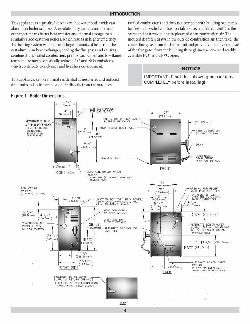
figure 1 - boiler dimensions
This appliance is a gas-fired direct vent hot water boiler with cast aluminum boiler sections. A revolutionary cast aluminum heat exchanger means better heat transfer and thermal storage than similarly sized cast iron boilers, which results in higher efficiency. The heating system water absorbs large amounts of heat from the cast aluminum heat exchanger, cooling the flue gases and causing condensation. Sealed combustion, premix gas burner, and low flame temperature means drastically reduced CO and NOx emissions, which contribute to a cleaner and healthier environment.
This appliance, unlike normal residential atmospheric and induced draft units, takes its combustion air directly from the outdoors
(sealed combustion) and does not compete with building occupants for fresh air. Sealed combustion (also known as “direct vent”) is the safest and best way to obtain plenty of clean combustion air. The induced draft fan draws in the outside combustion air, then takes the cooler flue gases from the boiler unit and provides a positive removal of the flue gases from the building through inexpensive and readily available PVC and CPVC pipes.
NOTICE
IMPORTANT: Read the following instructions cOMPLeTeLY before installing!
5
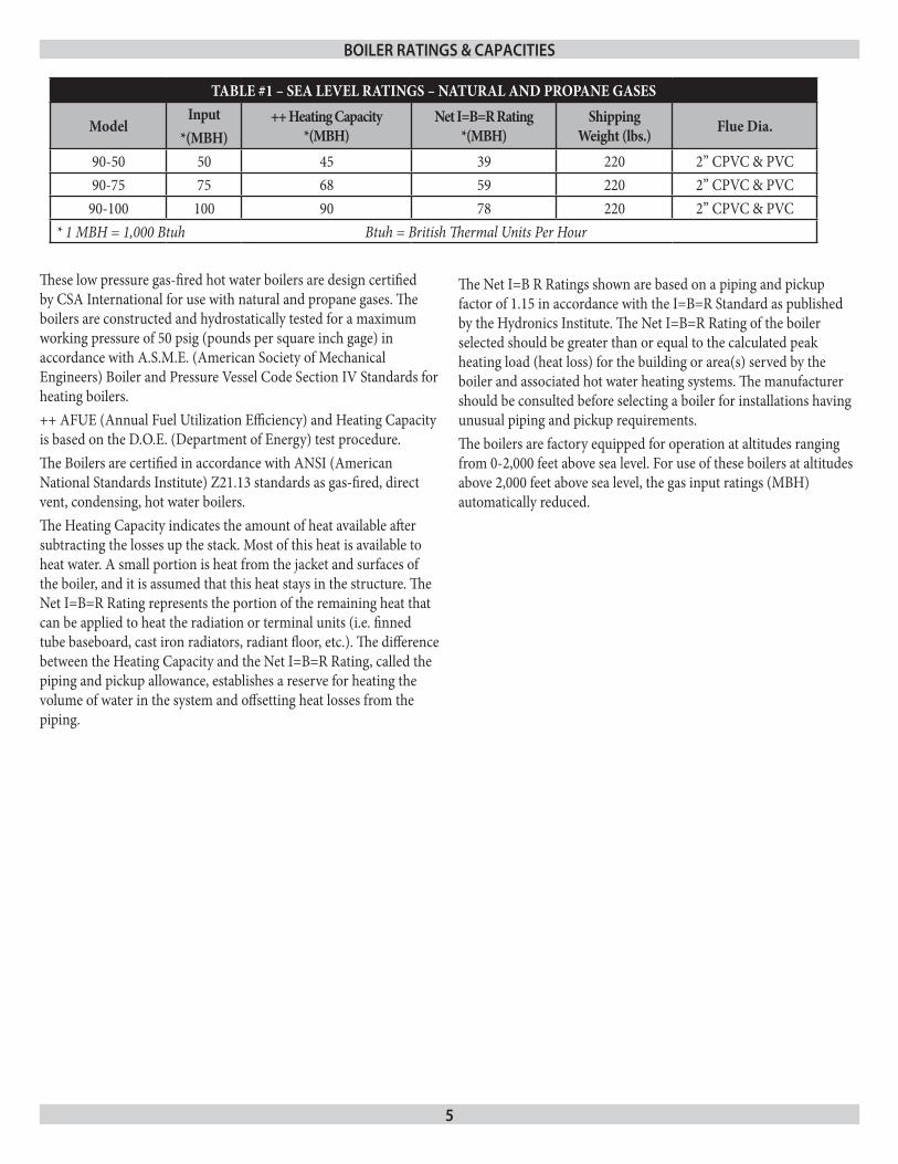
TABLE #1 – SEA LEVEL RATINGS – NATURAL AND PROPANE GASES
ModelInput
*(MBH)++ Heating Capacity
*(MBH)Net I=B=R Rating
*(MBH)Shipping
Weight (lbs.) Flue Dia.
90-50 50 45 39 220 2” CPVC & PVC90-75 75 68 59 220 2” CPVC & PVC
90-100 100 90 78 220 2” CPVC & PVC* 1 MBH = 1,000 Btuh Btuh = British Thermal Units Per Hour
boiler raTings & CapaCiTies
These low pressure gas-fired hot water boilers are design certified by CSA International for use with natural and propane gases. The boilers are constructed and hydrostatically tested for a maximum working pressure of 50 psig (pounds per square inch gage) in accordance with A.S.M.E. (American Society of Mechanical Engineers) Boiler and Pressure Vessel Code Section IV Standards for heating boilers.++ AFUE (Annual Fuel Utilization Efficiency) and Heating Capacity is based on the D.O.E. (Department of Energy) test procedure.The Boilers are certified in accordance with ANSI (American National Standards Institute) Z21.13 standards as gas-fired, direct vent, condensing, hot water boilers. The Heating Capacity indicates the amount of heat available after subtracting the losses up the stack. Most of this heat is available to heat water. A small portion is heat from the jacket and surfaces of the boiler, and it is assumed that this heat stays in the structure. The Net I=B=R Rating represents the portion of the remaining heat that can be applied to heat the radiation or terminal units (i.e. finned tube baseboard, cast iron radiators, radiant floor, etc.). The difference between the Heating Capacity and the Net I=B=R Rating, called the piping and pickup allowance, establishes a reserve for heating the volume of water in the system and offsetting heat losses from the piping.
The Net I=B R Ratings shown are based on a piping and pickup factor of 1.15 in accordance with the I=B=R Standard as published by the Hydronics Institute. The Net I=B=R Rating of the boiler selected should be greater than or equal to the calculated peak heating load (heat loss) for the building or area(s) served by the boiler and associated hot water heating systems. The manufacturer should be consulted before selecting a boiler for installations having unusual piping and pickup requirements.The boilers are factory equipped for operation at altitudes ranging from 0-2,000 feet above sea level. For use of these boilers at altitudes above 2,000 feet above sea level, the gas input ratings (MBH) automatically reduced.
6
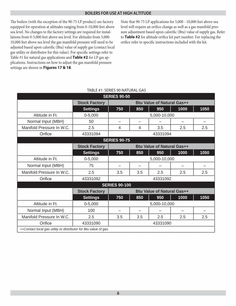
TABLE #1: SERIES 90 NATURAL GAS
SERIES 90-50Stock Factory Btu Value of Natural Gas++
Settings 750 850 950 1000 1050Altitude in Ft. 0-5,000 5,000-10,000
Normal Input (MBH) 50 – – – – –Manifold Pressure In W.C. 2.5 4 4 3.5 2.5 2.5
Orifice 43331094 43331094SERIES 90-75
Stock Factory Btu Value of Natural Gas++Settings 750 850 950 1000 1050
Altitude in Ft. 0-5,000 5,000-10,000Normal Input (MBH) 75 – – – – –
Manifold Pressure In W.C. 2.5 3.5 3.5 2.5 2.5 2.5Orifice 43331092 43331092
SERIES 90-100Stock Factory Btu Value of Natural Gas++
Settings 750 850 950 1000 1050Altitude in Ft. 0-5,000 5,000-10,000
Normal Input (MBH) 100 – – – – –Manifold Pressure In W.C. 2.5 3.5 3.5 2.5 2.5 2.5
Orifice 43331090 43331090++Contact local gas utility or distributor for Btu value of gas.
boilers for use aT HigH alTiTude
The boilers (with the exception of the 90-75 LP product) are factory equipped for operation at altitudes ranging from 0-10,000 feet above sea level. No changes to the factory settings are required for instal-lations from 0-5,000 feet above sea level. For altitudes from 5,000-10,000 feet above sea level the gas manifold pressure will need to be adjusted based upon calorific (Btu) value of supply gas (contact local gas utility or distributor for this value). For specific settings refer to Table #1 for natural gas applications and Table #2 for LP gas ap-plications. Instructions on how to adjust the gas manifold pressure settings are shown in Figures 17 & 18.
Note that 90-75 LP applications for 5,000 - 10,000 feet above sea level will require an orifice change as well as a gas manifold pres-sure adjustment based upon calorific (Btu) value of supply gas. Refer to Table #2 for altitude orifice kit part number. For replacing the orifice refer to specific instructions included with the kit.
7
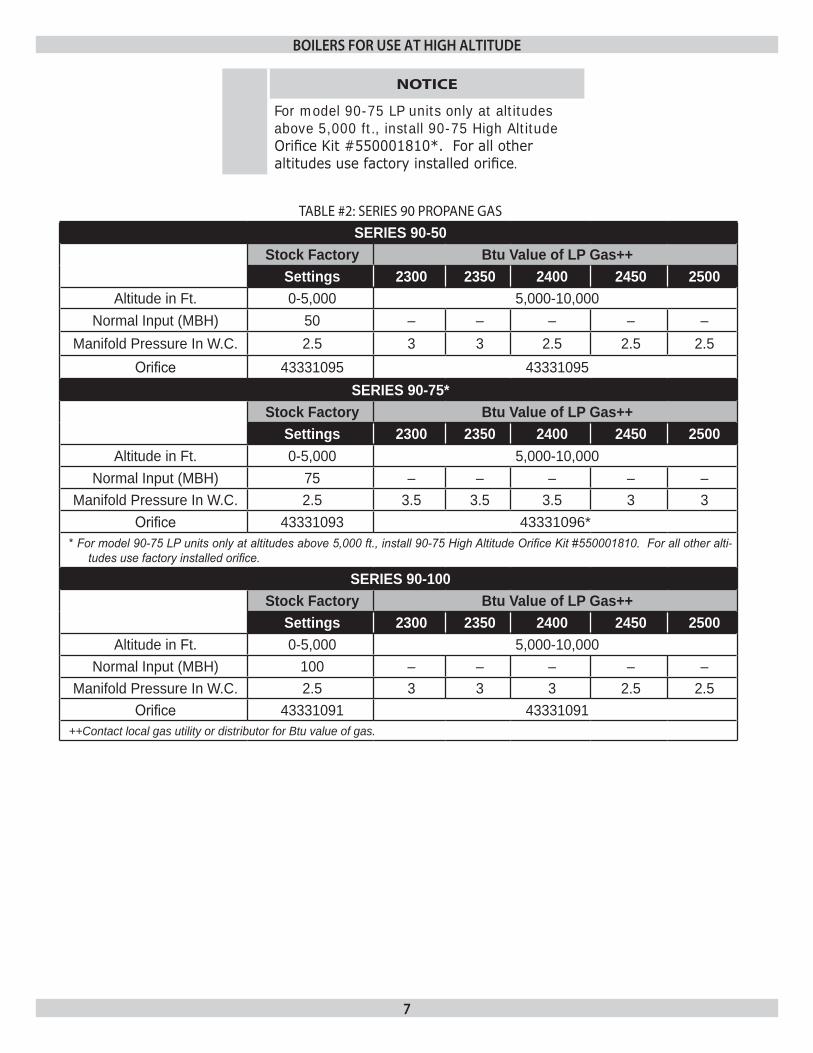
TABLE #2: SERIES 90 PROPANE GAS
SERIES 90-50Stock Factory Btu Value of LP Gas++
Settings 2300 2350 2400 2450 2500Altitude in Ft. 0-5,000 5,000-10,000
Normal Input (MBH) 50 – – – – –Manifold Pressure In W.C. 2.5 3 3 2.5 2.5 2.5
Orifice 43331095 43331095SERIES 90-75*
Stock Factory Btu Value of LP Gas++Settings 2300 2350 2400 2450 2500
Altitude in Ft. 0-5,000 5,000-10,000Normal Input (MBH) 75 – – – – –
Manifold Pressure In W.C. 2.5 3.5 3.5 3.5 3 3Orifice 43331093 43331096*
* For model 90-75 LP units only at altitudes above 5,000 ft., install 90-75 High Altitude Orifice Kit #550001810. For all other alti-tudes use factory installed orifice.
SERIES 90-100Stock Factory Btu Value of LP Gas++
Settings 2300 2350 2400 2450 2500Altitude in Ft. 0-5,000 5,000-10,000
Normal Input (MBH) 100 – – – – –Manifold Pressure In W.C. 2.5 3 3 3 2.5 2.5
Orifice 43331091 43331091++Contact local gas utility or distributor for Btu value of gas.
boilers for use aT HigH alTiTude
NOTICE
For model 90-75 LP units only at altitudes above 5,000 ft., install 90-75 high Altitude Orifice Kit #550001810*. For all other altitudes use factory installed orifice.
8
Complete all of the following prior to installing the boiler.
CodesThis boiler product is a gas-fired, direct vent, condensing boiler and must be installed to conform to the requirements of the authority having jursidiction or, in the absence of such requirements:United States - National Fuel Gas Code (NFPA-54/ANSI Z223.1).Canada - National Gas and Propane Installation Code, Can/CSA B149.1.
Where required by the authority having jurisdiction, the installation must conform to the American Society of Mechanical Engineers Safety Code for Controls and Safety Devices for Automatically Fired Boilers, No.CSD-1.
NOTICE
Important - In the state of Massachusetts this product must be installed by a licensed plumber or gas fitter and the installation must be in accordance with 248 cMR.
Installers - Follow local regulations with respect to installation of CO (Carbon Monoxide) Detectors. Follow maintenance recommen-dations in this manual.
Installation Requirements Specific To The State Of Massachusetts For Direct Vent, Mechanical Vent, And Domestic Hot Water Appliances
For all side wall horizontally vented gas fueled equipment installed in every dwelling, building or structure used in whole or in part for residential purposes, including those owned or operated by the commonwealth and where the side wall exhaust vent termination is less than seven (7) feet above finished grade in the area of the vent-ing, including but not limited to decks and porches, the following requirements shall be satisfied:
Installation of carbon monoxide detectors: at the time of instal-1. lation of the side wall horizontal vented gas fueled equipment, the installing plumber or gasfitter shall observe that a hard wired carbon monoxide detector with an alarm and battery back-up is installed on the floor level where the gas equipment is to be installed. In addition, the installing plumber or gasfitter shall observe that a battery operated or hard wired carbon mon-oxide detector with an alarm is installed on each additional level of the dwelling, building or structure served by the side wall horizontal vented gas fueled equipment. It shall be the respon-sibility of the property owner to secure the services of qualified licensed professionals for the installation of hard wired carbon monoxide detectors.
Read the entire installation manual before beginning the instal-1. lation. Failure to follow these rules for safe installation and operation and these instructions could cause a malfunction of the boiler and result in death, serious bodily injury, and/or property damage.Check all applicable state and local building codes and util-2. ity company requirements before installation. The installation must conform with these requirements in their entirety. In the absence of these codes, use NFPA Installation Codes and good industry practice.Before servicing the boiler - allow the boiler to cool. Always 3. shut off any electricity and gas supply connected to the boiler prior to servicing.Inspect gas line for leaks.4.
Be certain gas input rate is correct. Over firing may result in 5. early failure of the boiler sections. This may cause dangerous operation. Under firing may result in too much air for the pre-mix burner causing poor or loss of combustion.Never vent the products of combustion from this boiler to an 6. enclosed space. Always vent to the outdoors. Never vent to another room or to inside a building.Be sure there is adequate outdoor air supply to boiler for com-7. plete combustion.
Follow a regular service and maintenance schedule for efficient 8. and safe operation. Keep boiler area clean of debris and free of combustible and 9. flammable materials.Proper through the wall or through the roof combustion vent-10. ing shall be in accordance with the materials and methods described in this manual. Installation must comply with local codes.This boiler and related hot water heating systems are not do it 11. yourself items. They must be installed and serviced by qualified professionals.
rules for safe insTallaTion and operaTion
before insTalling THe boiler
!
WARNING
This boiler has been equipped for residential installations. If used for commercial applications, any additional code requirements must be adhered to for installation. This may require additional controls including but not limited to a low water cut off, a manual reset high temperature limit, and wiring and/or piping modifications. The manufacturer is not responsible for any field installation changes made to a boiler installation which are not described or acknowledged in this manual.
9
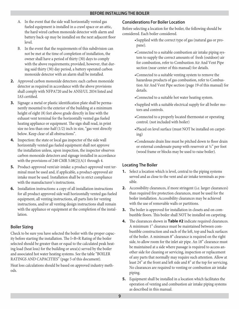
In the event that the side wall horizontally vented gas A. fueled equipment is installed in a crawl space or an attic, the hard wired carbon monoxide detector with alarm and battery back-up may be installed on the next adjacent floor level.In the event that the requirements of this subdivision can B. not be met at the time of completion of installation, the owner shall have a period of thirty (30) days to comply with the above requirements; provided, however, that dur-ing said thirty (30) day period, a battery operated carbon monoxide detector with an alarm shall be installed.
Approved carbon monoxide detectors: each carbon monoxide 2. detector as required in accordance with the above provisions shall comply with NFPA720 and be ANSI/UL 2034 listed and IAS certified.Signage: a metal or plastic identification plate shall be perma-3. nently mounted to the exterior of the building at a minimum height of eight (8) feet above grade directly in line with the exhaust vent terminal for the horizontally vented gas fueled heating appliance or equipment. The sign shall read, in print size no less than one-half (1/2) inch in size, “gas vent directly below. Keep clear of all obstructions”.Inspection: the state or local gas inspector of the side wall 4. horizontally vented gas fueled equipment shall not approve the installation unless, upon inspection, the inspector observes carbon monoxide detectors and signage installed in accordance with the provisions of 248 CMR 5.08(2)(A)1 through 4.Product-approved vent/air-intake: a product-approved vent ter-5. minal must be used and, if applicable, a product-approved air intake must be used. Installation shall be in strict compliance with the manufacturer’s instructions.Installation instructions: a copy of all installation instructions 6. for all product approved side wall horizontally vented gas fueled equipment, all venting instructions, all parts lists for venting instructions, and/or all venting design instructions shall remain with the appliance or equipment at the completion of the instal-lation.
boiler sizing Check to be sure you have selected the boiler with the proper capac-ity before starting the installation. The I=B=R Rating of the boiler selected should be greater than or equal to the calculated peak heat-ing load (heat loss) for the building or area(s) served by the boiler and associated hot water heating systems. See the table “BOILER RATINGS AND CAPACITIES” (page 5 of this document). Heat loss calculations should be based on approved industry meth-ods.
Considerations for boiler locationBefore selecting a location for the boiler, the following should be considered. Each boiler considered.
Supplied with the correct type of gas (natural gas or pro-•pane).
Connected to a suitable combustion air intake piping sys-•tem to supply the correct amounts of fresh (outdoor) air for combustion, refer to Combustion Air And Vent Pipe section (near center of this manual) for details.
Connected to a suitable venting system to remove the •hazardous products of gas combustion, refer to Combus-tion Air And Vent Pipe section (page 19 of this manual) for details.
Connected to a suitable hot water heating system.•
Supplied with a suitable electrical supply for all boiler mo-•tors and controls.
Connected to a properly located thermostat or operating •control. (not included with boiler)
Placed on level surface (must NOT be installed on carpet-•ing)
Condensate drain line must be pitched down to floor drain •or external condensate pump with reservoir at ¼” per foot (wood frame or blocks may be used to raise boiler).
locating The boilerSelect a location which is level, central to the piping systems 1. served and as close to the vent and air intake terminals as pos-sible.Accessibility clearances, if more stringent (i.e. larger clearances) 2. than required fire protection clearances, must be used for the boiler installation. Accessibility clearances may be achieved with the use of removable walls or partitions.The boiler is approved for installation in closets and on com-3. bustible floors. This boiler shall NOT be installed on carpeting.The clearances shown in 4. Table #2 indicate required clearances. A minimum 1” clearance must be maintained between com-bustible construction and each of the left, top and back surfaces of the boiler. A minimum 8” clearance is required on the right side, to allow room for the inlet air pipe. An 18” clearance must be maintained at a side where passage is required to access an-other side for cleaning or servicing, inspection or replacement of any parts that normally may require such attention. Allow at least 24” at the front and left side and 8” at the top for servicing. No clearances are required to venting or combustion air intake piping.Equipment shall be installed in a location which facilitates the 5. operation of venting and combustion air intake piping systems as described in this manual.
before insTalling THe boiler
10
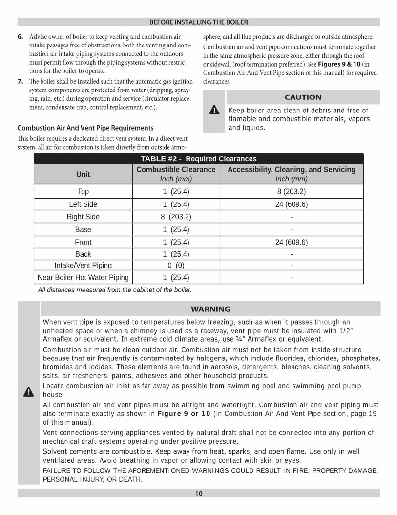
TABLE #2 - Required Clearances
Unit Combustible ClearanceInch (mm)
Accessibility, Cleaning, and Servicing Inch (mm)
Top 1 (25.4) 8 (203.2)Left Side 1 (25.4) 24 (609.6)
Right Side 8 (203.2) -Base 1 (25.4) -Front 1 (25.4) 24 (609.6)Back 1 (25.4) -
Intake/Vent Piping 0 (0) -Near Boiler Hot Water Piping 1 (25.4) -All distances measured from the cabinet of the boiler.
Advise owner of boiler to keep venting and combustion air 6. intake passages free of obstructions. both the venting and com-bustion air intake piping systems connected to the outdoors must permit flow through the piping systems without restric-tions for the boiler to operate.The boiler shall be installed such that the automatic gas ignition 7. system components are protected from water (dripping, spray-ing, rain, etc.) during operation and service (circulator replace-ment, condensate trap, control replacement, etc.).
Combustion air and Vent pipe requirementsThis boiler requires a dedicated direct vent system. In a direct vent system, all air for combustion is taken directly from outside atmo-
sphere, and all flue products are discharged to outside atmosphere.Combustion air and vent pipe connections must terminate together in the same atmospheric pressure zone, either through the roof or sidewall (roof termination preferred). See Figures 9 & 10 (in Combustion Air And Vent Pipe section of this manual) for required clearances.
before insTalling THe boiler
! CAUTION
keep boiler area clean of debris and free of flamable and combustible materials, vapors and liquids.
!
WARNING
When vent pipe is exposed to temperatures below freezing, such as when it passes through an unheated space or when a chimney is used as a raceway, vent pipe must be insulated with 1/2” Armaflex or equivalent. In extreme cold climate areas, use ¾” Armaflex or equivalent.combustion air must be clean outdoor air. combustion air must not be taken from inside structure because that air frequently is contaminated by halogens, which include fluorides, chlorides, phosphates, bromides and iodides. These elements are found in aerosols, detergents, bleaches, cleaning solvents, salts, air fresheners, paints, adhesives and other household products.Locate combustion air inlet as far away as possible from swimming pool and swimming pool pump house.All combustion air and vent pipes must be airtight and watertight. combustion air and vent piping must also terminate exactly as shown in Figure 9 or 10 (in combustion Air And Vent Pipe section, page 19 of this manual).Vent connections serving appliances vented by natural draft shall not be connected into any portion of mechanical draft systems operating under positive pressure.Solvent cements are combustible. Keep away from heat, sparks, and open flame. Use only in well ventilated areas. Avoid breathing in vapor or allowing contact with skin or eyes.FAILuRe TO FOLLOW The AFOReMeNTIONeD WARNINGS cOuLD ReSuLT IN FIRe, PROPeRTY DAMAGe, PeRSONAL INJuRY, OR DeATh.
11
Condensate drain requirementsCondensate drain line to be pitched down to floor drain at a mini-mum of ¼” per foot. An external condensate pump (not furnished) may be used if floor drain is not available. The condensate pump must be designed for flue gas condensate application.
before insTalling THe boiler
NOTICE
1. condensate trap is built into the boiler, an external trap is not required and should not be used.2. Wood frame or blocks may be used to raise the boiler to maintain drain pitch or to be above external condensate pump reservoir.3. There is a 115 Volt Ac receptacle provided on the service switch junction box which is located at the boiler right side, to provide power for an external condensate pump (if needed).
foundation requirementsBoiler must be placed on level surface. Boiler is NOT to be installed on carpeting.
NOTICE
If boiler is not level condensate drain lines will not function properly. Adjustable feet are located on the boiler to make up for minor surface irregularities or tilt.Wood frame or blocks may be used to raise boiler to maintain drain pitch or to be above external condensate pump reservoir.
removal of existing boiler from Common Vent systemWhen an existing boiler is removed from a common venting system, the common venting system is likely to be too large for proper vent-ing of the appliances remaining connected to it. At the time of re-
moval of an existing boiler, the following steps shall be followed with each appliance remaining connected to the common venting system placed in operation, while the other appliances remaining connected to the common venting system are not in operation.
Seal any unused openings in the common venting system.1.
Visually inspect the venting system for proper size and hori-2. zontal pitch and determine there is no blockage, or restrictions, leakage, corrosion and other deficiencies which could cause an unsafe condition.In-so-far as is practical, close all building doors and windows 3. and all doors between the space in which the appliances remain-ing connected to the common venting system are located and other spaces of the building. Turn on clothes dryer and any ap-pliance not connected to the common venting system. Turn on any exhaust fans, such as range hoods and bathroom exhaust, so they will operate at maximum speed. Do not operate a summer exhaust fan. Close fire dampers. Place in operation the appliance being inspected. Follow the 4. lighting instructions. Adjust thermostat so appliances will oper-ate continuously.Test for spillage at the draft hood relief opening after 5 minutes 5. of main burner operation. Use the flame of a match or candle, or the smoke from a cigarette, cigar or pipe.After it has been determined that each appliance remaining 6. connected to the common venting system properly vents when tested as outlined above, return doors, windows, exhaust fans, fire place dampers, and any other gas-burning appliance to their previous condition of use.Any improper operation of the common venting system should 7. be corrected so the installation conforms with the National Fuel Code, NFPA-54/ANSI -Z223.1 and/or the Natural Gas and Propane Installation Code, CAN/CSA B149.1.. When resizing any portion of the common venting system, the common vent-ing system should be resized to approach the minimum size as determined using the appropriate tables in Chapter 13 of the National Fuel Gas Code, NFPA-54/ANSI- Z223.1 and/or the Natural Gas and Propane Installation Code, CAN/CSA B149.1.
plaCing THe boiler
The boiler should be placed to provide the most direct connections to the combustion air, vent and system piping as possible.Place crated boiler as close to selected location as possible and uncrate boiler. The uncrated boiler may be moved into position with an appliance dolly or 2-wheel hand truck. The dolly or hand truck should be inserted under the left hand side of the boiler. It is possible to slide the boiler for a short distance on a smooth floor or surface.
NOTICE
Refer to manual section “locating the boiler” (page 9 of this manual), for required clearances for servicing and maintenance.
12
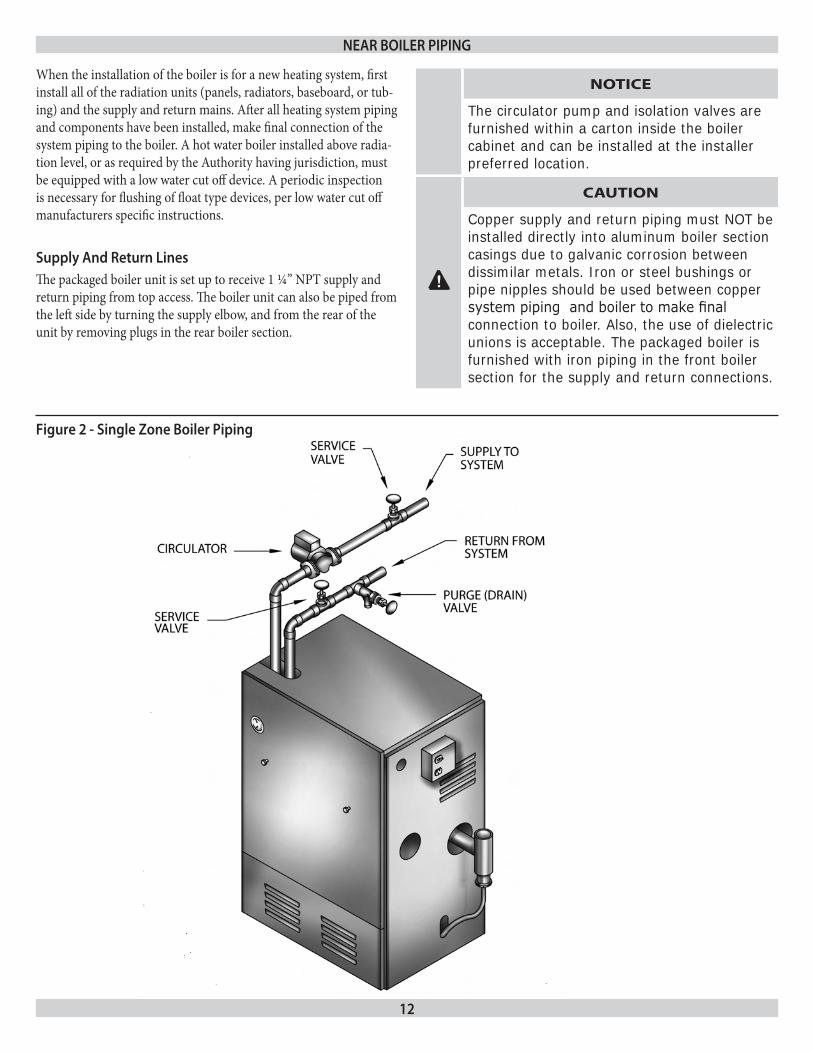
When the installation of the boiler is for a new heating system, first install all of the radiation units (panels, radiators, baseboard, or tub-ing) and the supply and return mains. After all heating system piping and components have been installed, make final connection of the system piping to the boiler. A hot water boiler installed above radia-tion level, or as required by the Authority having jurisdiction, must be equipped with a low water cut off device. A periodic inspection is necessary for flushing of float type devices, per low water cut off manufacturers specific instructions.
supply and return linesThe packaged boiler unit is set up to receive 1 ¼” NPT supply and return piping from top access. The boiler unit can also be piped from the left side by turning the supply elbow, and from the rear of the unit by removing plugs in the rear boiler section.
near boiler piping
!
CAUTION
copper supply and return piping must NOT be installed directly into aluminum boiler section casings due to galvanic corrosion between dissimilar metals. Iron or steel bushings or pipe nipples should be used between copper system piping and boiler to make final connection to boiler. Also, the use of dielectric unions is acceptable. The packaged boiler is furnished with iron piping in the front boiler section for the supply and return connections.
figure 2 - single Zone boiler piping
NOTICE
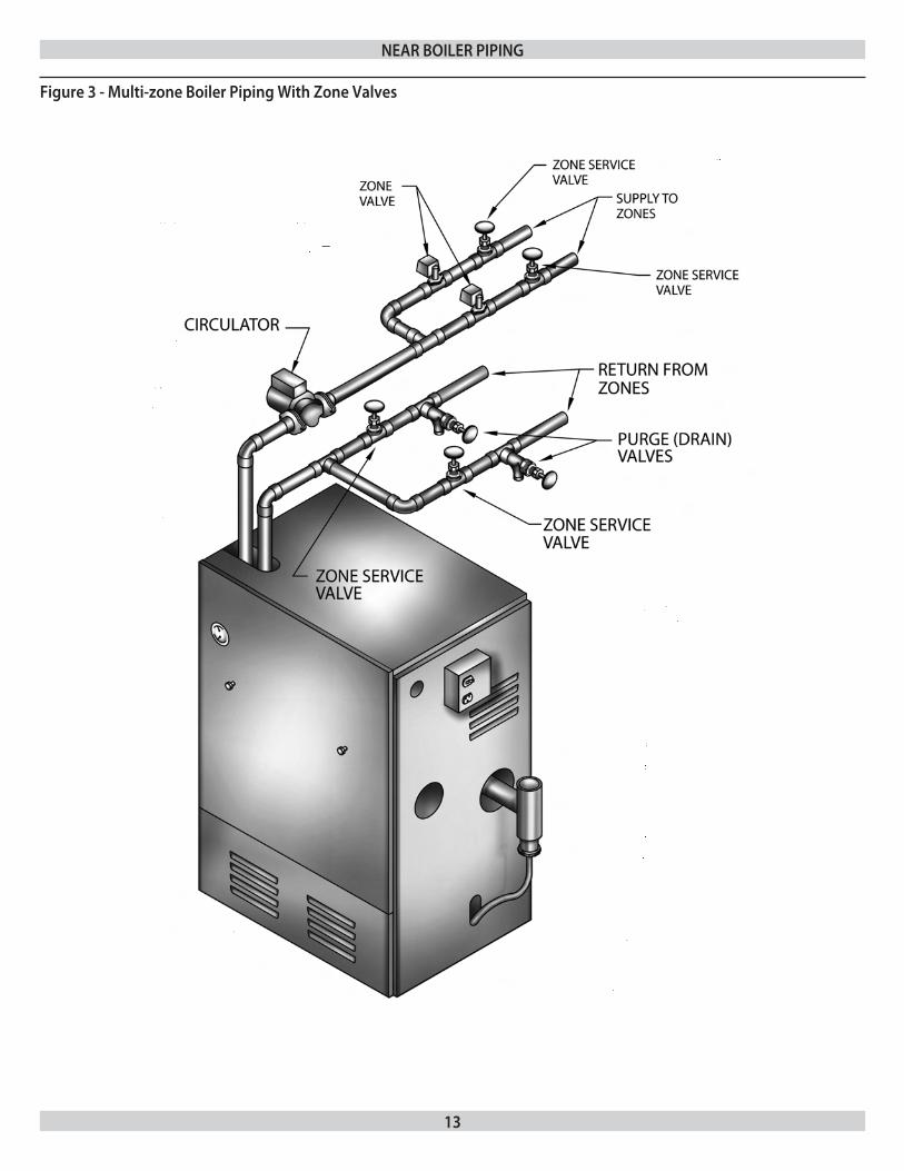
The circulator pump and isolation valves are furnished within a carton inside the boiler cabinet and can be installed at the installer preferred location.
13
figure 3 - multi-zone boiler piping With Zone Valves
near boiler piping
14
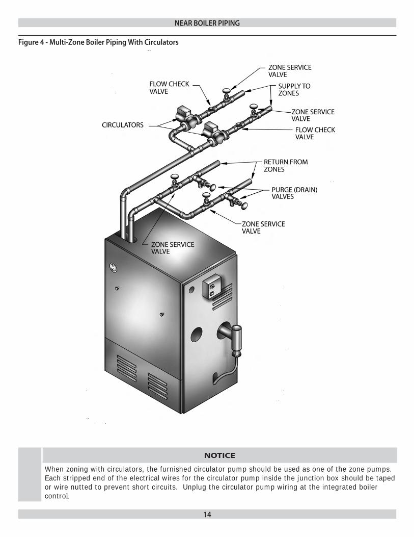
figure 4 - multi-Zone boiler piping With Circulators
near boiler piping
NOTICE
When zoning with circulators, the furnished circulator pump should be used as one of the zone pumps. each stripped end of the electrical wires for the circulator pump inside the junction box should be taped or wire nutted to prevent short circuits. unplug the circulator pump wiring at the integrated boiler control.
15
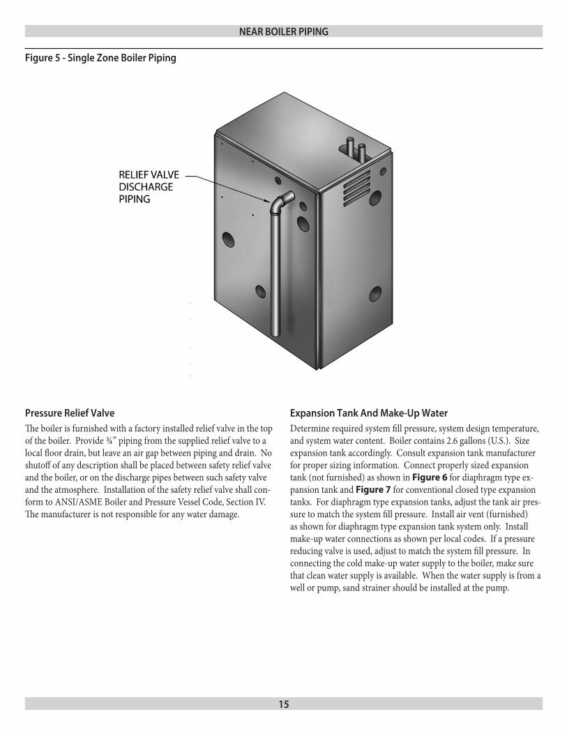
pressure relief ValveThe boiler is furnished with a factory installed relief valve in the top of the boiler. Provide ¾” piping from the supplied relief valve to a local floor drain, but leave an air gap between piping and drain. No shutoff of any description shall be placed between safety relief valve and the boiler, or on the discharge pipes between such safety valve and the atmosphere. Installation of the safety relief valve shall con-form to ANSI/ASME Boiler and Pressure Vessel Code, Section IV. The manufacturer is not responsible for any water damage.
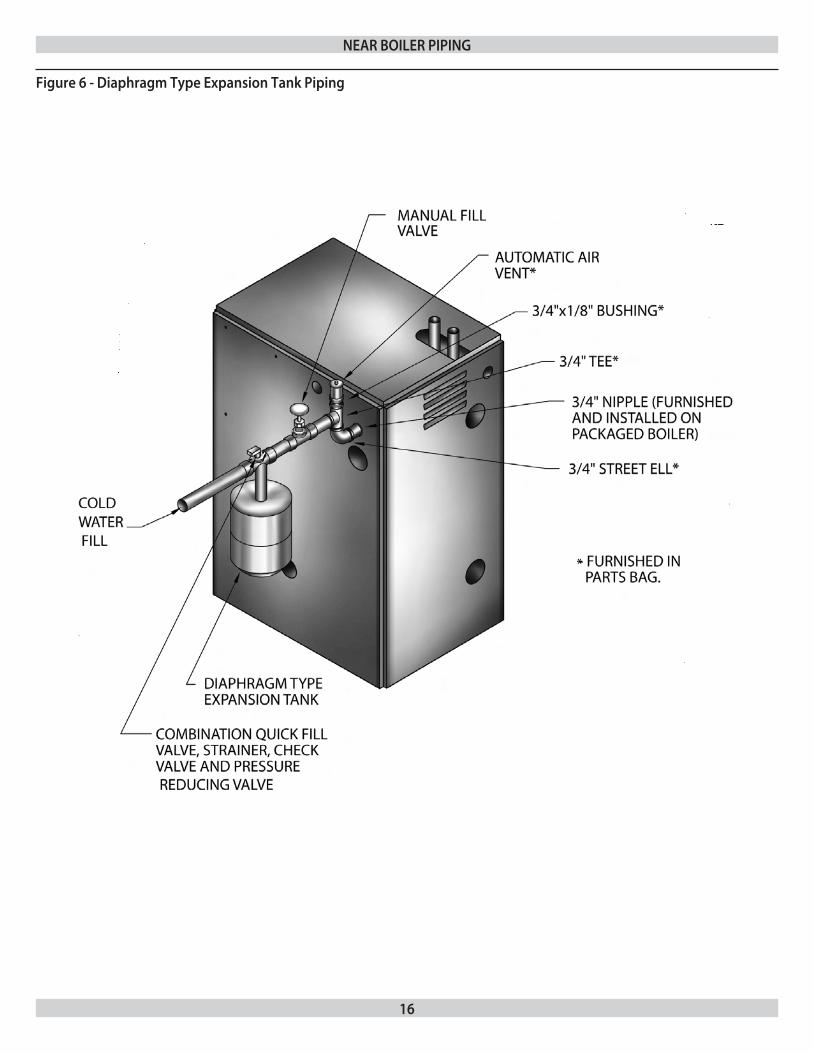
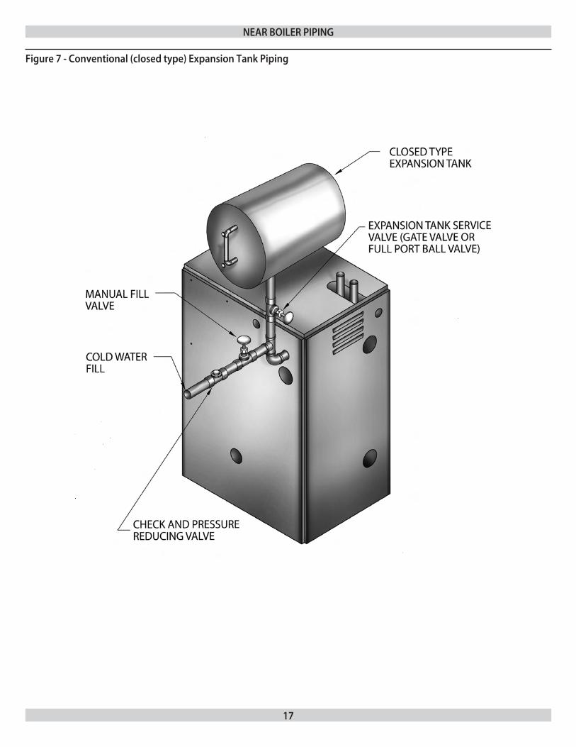
expansion Tank and make-up WaterDetermine required system fill pressure, system design temperature, and system water content. Boiler contains 2.6 gallons (U.S.). Size expansion tank accordingly. Consult expansion tank manufacturer for proper sizing information. Connect properly sized expansion tank (not furnished) as shown in Figure 6 for diaphragm type ex-pansion tank and Figure 7 for conventional closed type expansion tanks. For diaphragm type expansion tanks, adjust the tank air pres-sure to match the system fill pressure. Install air vent (furnished) as shown for diaphragm type expansion tank system only. Install make-up water connections as shown per local codes. If a pressure reducing valve is used, adjust to match the system fill pressure. In connecting the cold make-up water supply to the boiler, make sure that clean water supply is available. When the water supply is from a well or pump, sand strainer should be installed at the pump.
figure 5 - single Zone boiler piping
near boiler piping
16
figure 6 - diaphragm Type expansion Tank piping
near boiler piping
17
figure 7 - Conventional (closed type) expansion Tank piping
near boiler piping
18
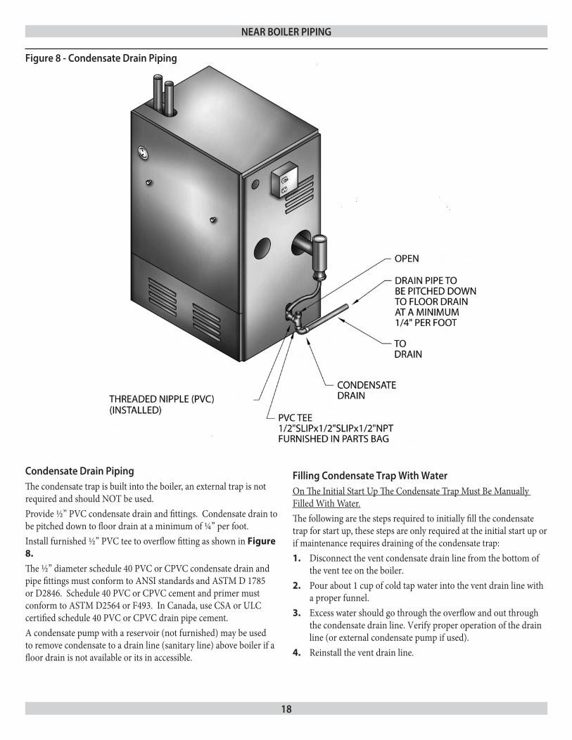
Condensate drain pipingThe condensate trap is built into the boiler, an external trap is not required and should NOT be used.Provide ½” PVC condensate drain and fittings. Condensate drain to be pitched down to floor drain at a minimum of ¼” per foot.Install furnished ½” PVC tee to overflow fitting as shown in Figure 8.
The ½” diameter schedule 40 PVC or CPVC condensate drain and pipe fittings must conform to ANSI standards and ASTM D 1785 or D2846. Schedule 40 PVC or CPVC cement and primer must conform to ASTM D2564 or F493. In Canada, use CSA or ULC certified schedule 40 PVC or CPVC drain pipe cement.A condensate pump with a reservoir (not furnished) may be used to remove condensate to a drain line (sanitary line) above boiler if a floor drain is not available or its in accessible.
figure 8 - Condensate drain piping
near boiler piping
filling Condensate Trap With Water On The Initial Start Up The Condensate Trap Must Be Manually Filled With Water.The following are the steps required to initially fill the condensate trap for start up, these steps are only required at the initial start up or if maintenance requires draining of the condensate trap:
Disconnect the vent condensate drain line from the bottom of 1. the vent tee on the boiler.Pour about 1 cup of cold tap water into the vent drain line with 2. a proper funnel.Excess water should go through the overflow and out through 3. the condensate drain line. Verify proper operation of the drain line (or external condensate pump if used).Reinstall the vent drain line.4.
19
Connections and TerminationProvisions for combustion and ventilation air must be in accordance with section, Air For Combustion and Ventilation, of the National Fuel Gas Code,ANSI 2223.1/NFPA54, or Sections 8.2, 8.3 or 8.4 of National Gas and Propane Installation Code, CAN/CGA-B 149.1 , or applicable provisions of the local building code.These boilers require a dedicated direct vent system. All air for com-bustion is taken directly from outdoors through the combustion air intake pipe. All flue products are discharged to the outdoors through the vent pipe.
Refer to Combustion Air And Vent Pipe section that follows, 1. also see Figures 9 & 10 for combustion air and vent pipe roof and sidewall termination. (Roof termination is preferred) Combustion air and vent pipes must terminate together in same atmo spheric pressure zone as shown. Construction through which vent and air intake pipes may be installed is a maximum 24 inches, minimum ¼” thickness.Combustion air and vent pipe fittings must conform to 2. American National Standards Institute (ANSI) standards and American Society for Testing and Materials (ASTM) standards D1784 (schedule-40 CPVC), D1785 (schedule-40 PVC), D2665 (PVC-DWV), D2241 (SDR-21 and SDR-26 PVC), D2661 (ABS-DWV), or F628 (schedule-40 ABS). Pipe cement and primer must conform to ASTM standards D2564 (PVC) or D2235 (ABS).
In Canada construct all combustion air and vent pipes for this unit of CSA or ULC certified schedule-40 CPVC, schedule-40 PVC, PVC-DWV or ABS-DWV pipe and pipe cement. SDR pipe is NOT approved in Canada.
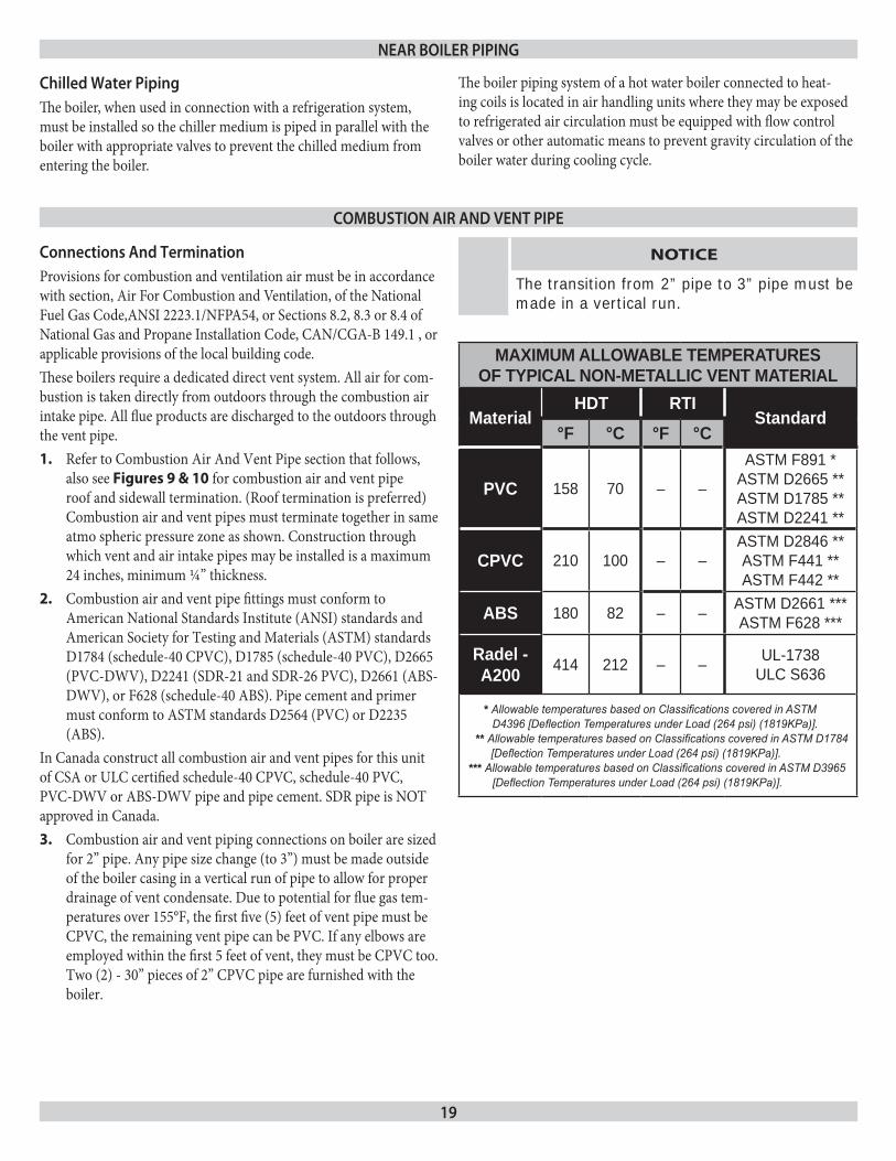
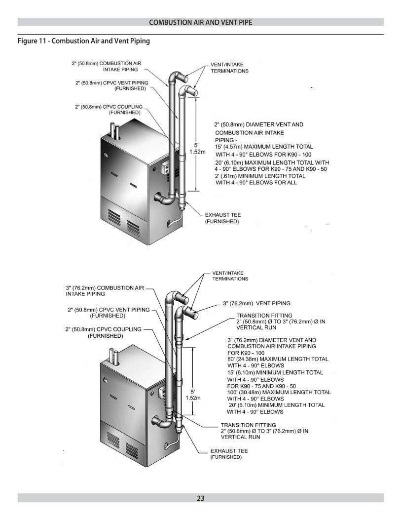
Combustion air and vent piping connections on boiler are sized 3. for 2” pipe. Any pipe size change (to 3”) must be made outside of the boiler casing in a vertical run of pipe to allow for proper drainage of vent condensate. Due to potential for flue gas tem-peratures over 155°F, the first five (5) feet of vent pipe must be CPVC, the remaining vent pipe can be PVC. If any elbows are employed within the first 5 feet of vent, they must be CPVC too. Two (2) - 30” pieces of 2” CPVC pipe are furnished with the boiler.
NOTICE
The transition from 2” pipe to 3” pipe must be made in a vertical run.
MAxIMUM ALLOwABLE TEMPERATURES OF TyPICAL NON-METALLIC VENT MATERIAL
MaterialHDT RTI
Standard°F °C °F °C
PVC 158 70 – –
ASTM F891 *ASTM D2665 **ASTM D1785 **ASTM D2241 **
CPVC 210 100 – –ASTM D2846 **ASTM F441 **ASTM F442 **
ABS 180 82 – – ASTM D2661 ***ASTM F628 ***
Radel - A200 414 212 – – UL-1738
ULC S636
* Allowable temperatures based on Classifications covered in ASTM D4396 [Deflection Temperatures under Load (264 psi) (1819KPa)].
** Allowable temperatures based on Classifications covered in ASTM D1784 [Deflection Temperatures under Load (264 psi) (1819KPa)].
*** Allowable temperatures based on Classifications covered in ASTM D3965 [Deflection Temperatures under Load (264 psi) (1819KPa)].
Chilled Water pipingThe boiler, when used in connection with a refrigeration system, must be installed so the chiller medium is piped in parallel with the boiler with appropriate valves to prevent the chilled medium from entering the boiler.
near boiler piping
CombusTion air and VenT pipe
The boiler piping system of a hot water boiler connected to heat-ing coils is located in air handling units where they may be exposed to refrigerated air circulation must be equipped with flow control valves or other automatic means to prevent gravity circulation of the boiler water during cooling cycle.
20
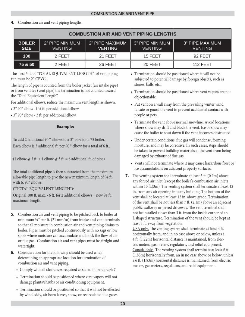
Combustion air and vent piping lengths:4.
CombusTion air and VenT pipe
Example:
To add 2 additional 90 ° elbows to a 3” pipe for a 75 boiler.Each elbow is 3 additional ft. per 90 ° elbow for a total of 6 ft..
(1 elbow @ 3 ft. + 1 elbow @ 3 ft. = 6 additional ft. of pipe)
The total additional pipe is then subtracted from the maximum allowable pipe length to give the new maximum length of 94 ft. with 6, 90° elbows. (“TOTAL EQUIVALENT LENGTH”):Original 100 ft. max. - 6 ft. for 2 additional elbows = new 94 ft. maximum length.
Combustion air and vent piping to be pitched back to boiler at 5. minimum ¼” per ft. (21 mm/m) from intake and vent terminals so that all moisture in combustion air and vent piping drains to boiler. Pipes must be pitched continuously with no sags or low spots where moisture can accumulate and block the flow of air or flue gas. Combustion air and vent pipes must be airtight and watertight.Consideration for the following should be used when 6. determining an appropriate location for termination of combustion air and vent piping.
Comply with all clearances required as stated in paragraph 7.•
Termination should be positioned where vent vapors will not •damage plants/shrubs or air conditioning equipment.
Termination should be positioned so that it will not be effected •by wind eddy, air born leaves, snow, or recirculated flue gases.
COMBUSTION AIR AND VENT PIPING LENGTHS
BOILER SIZE
2” PIPE MINIMUM VENTING
2” PIPE MAXIMUM VENTING
3” PIPE MINIMUM VENTING
3” PIPE MAXIMUM VENTING
100 2 FEET 21 FEET 15 FEET 92 FEET
75 & 50 2 FEET 26 FEET 20 FEET 112 FEET
Termination should be positioned where it will not be •subjected to potential damage by foreign objects, such as stones, balls, etc..
Termination should be positioned where vent vapors are not •objectionable.
Put vent on a wall away from the prevailing winter wind. •Locate or guard the vent to prevent accidental contact with people or pets.
Terminate the vent above normal snowline. Avoid locations •where snow may drift and block the vent. Ice or snow may cause the boiler to shut down if the vent becomes obstructed.
Under certain conditions, flue gas will condense, forming •moisture, and may be corrosive. In such cases, steps should be taken to prevent building materials at the vent from being damaged by exhaust of flue gas.
Vent shall not terminate where it may cause hazardous frost or •ice accumulations on adjacent property surfaces.
The venting system shall terminate at least 3 ft. (0.9m) above 7. any forced air inlet (except the boiler’s combustion air inlet) within 10 ft.(3m). The venting system shall terminate at least 12 in. from any air opening into any building. The bottom of the vent shall be located at least 12 in. above grade. Termination of the vent shall be not less than 7 ft. (2.1m) above an adjacent public walkway or paved driveway. The vent terminal shall not be installed closer than 3 ft. from the inside corner of an L shaped structure. Termination of the vent should be kept at least 3 ft. away from vegetation. USA only. The venting system shall terminate at least 4 ft. horizontally from, and in no case above or below, unless a 4 ft. (1.22m) horizontal distance is maintained, from elec-tric meters, gas meters, regulators, and relief equipment. Canada only. The venting system shall terminate at least 6 ft. (1.83m) horizontally from, an in no case above or below, unless a 6 ft. (1.83m) horizontal distance is maintained, from electric meters, gas meters, regulators, and relief equipment.
The first 5 ft. of “TOTAL EQUIVALENT LENGTH” of vent piping run must be 2” CPVC:The length of pipe is counted from the boiler jacket (air intake pipe) or from vent tee (vent pipe) the termination is not counted toward the “Total Equivalent Length”. For additional elbows, reduce the maximum vent length as shown: •2”90°elbow-1½ft.peradditionalelbow.•3”90°elbow-3ft.peradditionalelbow.
21
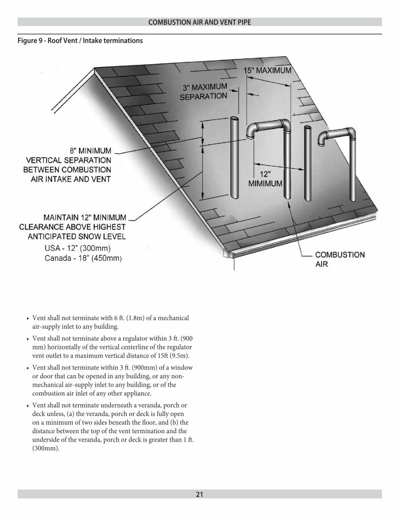
figure 9 - roof Vent / intake terminations
CombusTion air and VenT pipe
Vent shall not terminate with 6 ft. (1.8m) of a mechanical •air-supply inlet to any building.
Vent shall not terminate above a regulator within 3 ft. (900 •mm) horizontally of the vertical centerline of the regulator vent outlet to a maximum vertical distance of 15ft (9.5m).
Vent shall not terminate within 3 ft. (900mm) of a window •or door that can be opened in any building, or any non-mechanical air-supply inlet to any building, or of the combustion air inlet of any other appliance.
Vent shall not terminate underneath a veranda, porch or •deck unless, (a) the veranda, porch or deck is fully open on a minimum of two sides beneath the floor, and (b) the distance between the top of the vent termination and the underside of the veranda, porch or deck is greater than 1 ft. (300mm).
22
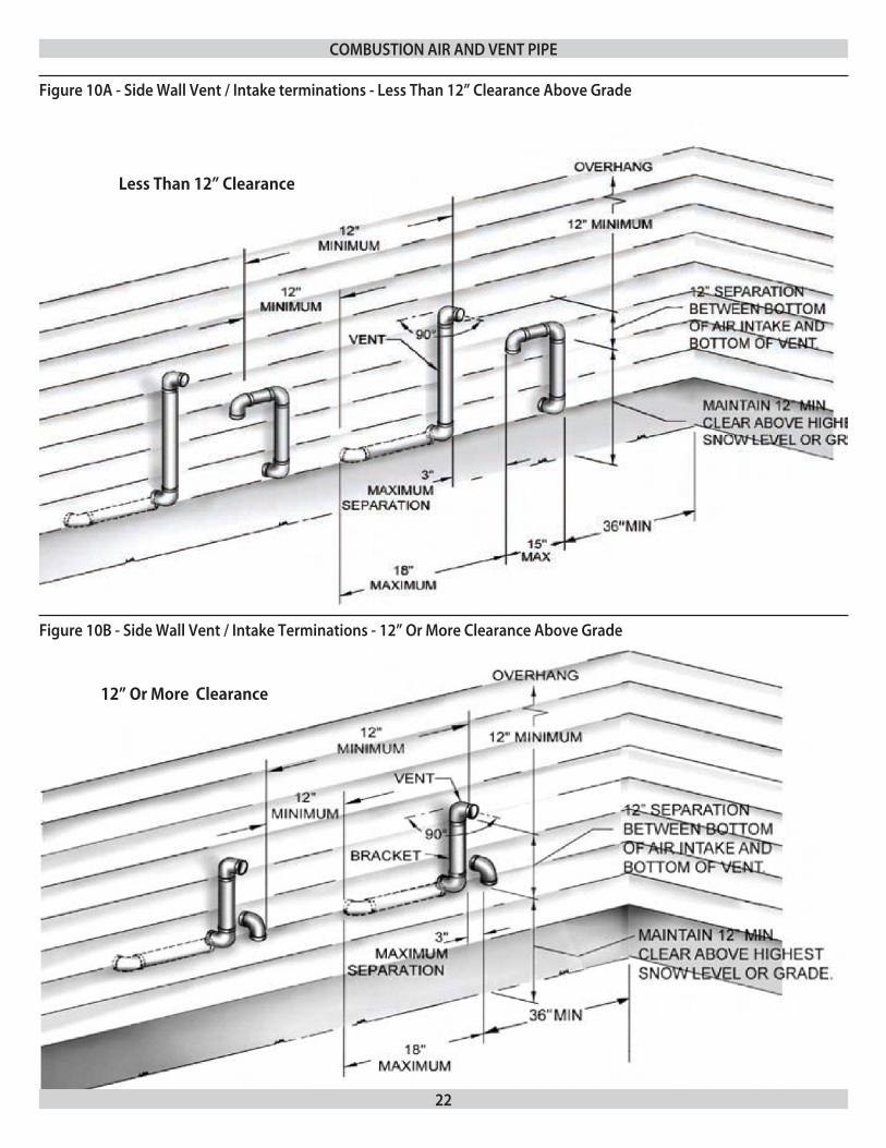
figure 10a - side Wall Vent / intake terminations - less Than 12” Clearance above grade
figure 10b - side Wall Vent / intake Terminations - 12” or more Clearance above grade
CombusTion air and VenT pipe
Less Than 12” Clearance
12” Or More Clearance
23
figure 11 - Combustion air and Vent piping
CombusTion air and VenT pipe
24
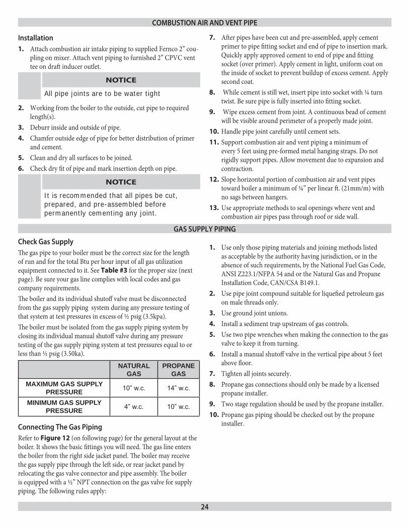
Check gas supplyThe gas pipe to your boiler must be the correct size for the length of run and for the total Btu per hour input of all gas utilization equipment connected to it. See Table #3 for the proper size (next page). Be sure your gas line complies with local codes and gas company requirements.The boiler and its individual shutoff valve must be disconnected from the gas supply piping system during any pressure testing of that system at test pressures in excess of ½ psig (3.5kpa).The boiler must be isolated from the gas supply piping system by closing its individual manual shutoff valve during any pressure testing of the gas supply piping system at test pressures equal to or less than ½ psig (3.50ka).
installationAttach combustion air intake piping to supplied Fernco 2” cou-1. pling on mixer. Attach vent piping to furnished 2” CPVC vent tee on draft inducer outlet.
NOTICE
All pipe joints are to be water tight
Working from the boiler to the outside, cut pipe to required 2. length(s).Deburr inside and outside of pipe.3.
Chamfer outside edge of pipe for better distribution of primer 4. and cement.Clean and dry all surfaces to be joined.5.
Check dry fit of pipe and mark insertion depth on pipe.6.
NOTICE
It is recommended that all pipes be cut, prepared, and pre-assembled before permanently cementing any joint.
After pipes have been cut and pre-assembled, apply cement 7. primer to pipe fitting socket and end of pipe to insertion mark. Quickly apply approved cement to end of pipe and fitting socket (over primer). Apply cement in light, uniform coat on the inside of socket to prevent buildup of excess cement. Apply second coat. While cement is still wet, insert pipe into socket with ¼ turn 8. twist. Be sure pipe is fully inserted into fitting socket. Wipe excess cement from joint. A continuous bead of cement 9. will be visible around perimeter of a properly made joint.Handle pipe joint carefully until cement sets.10.
Support combustion air and vent piping a minimum of 11. every 5 feet using pre-formed metal hanging straps. Do not rigidly support pipes. Allow movement due to expansion and contraction.Slope horizontal portion of combustion air and vent pipes 12. toward boiler a minimum of ¼” per linear ft. (21mm/m) with no sags between hangers.Use appropriate methods to seal openings where vent and 13. combustion air pipes pass through roof or side wall.
NATURAL GAS
PROPANE GAS
MAxIMUM GAS SUPPLy PRESSURE 10” w.c. 14” w.c.
MINIMUM GAS SUPPLy PRESSURE 4” w.c. 10” w.c.
CombusTion air and VenT pipe
gas supply piping
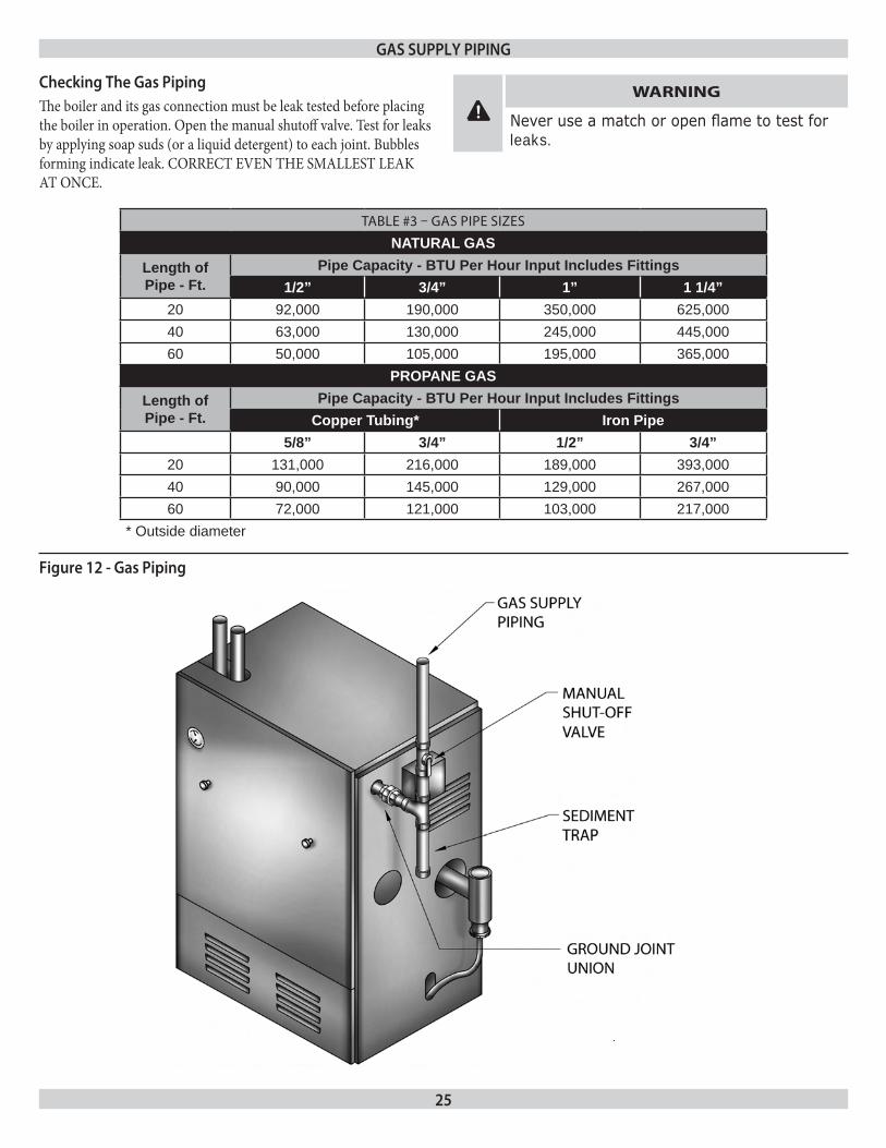
Connecting The gas pipingRefer to Figure 12 (on following page) for the general layout at the boiler. It shows the basic fittings you will need. The gas line enters the boiler from the right side jacket panel. The boiler may receive the gas supply pipe through the left side, or rear jacket panel by relocating the gas valve connector and pipe assembly. The boiler is equipped with a ½” NPT connection on the gas valve for supply piping. The following rules apply:
Use only those piping materials and joining methods listed 1. as acceptable by the authority having jurisdiction, or in the absence of such requirements, by the National Fuel Gas Code, ANSI Z223.1/NFPA 54 and or the Natural Gas and Propane Installation Code, CAN/CSA B149.1.Use pipe joint compound suitable for liquefied petroleum gas 2. on male threads only. Use ground joint unions.3.
Install a sediment trap upstream of gas controls.4.
Use two pipe wrenches when making the connection to the gas 5. valve to keep it from turning.Install a manual shutoff valve in the vertical pipe about 5 feet 6. above floor. Tighten all joints securely.7.
Propane gas connections should only be made by a licensed 8. propane installer.Two stage regulation should be used by the propane installer.9.
Propane gas piping should be checked out by the propane 10. installer.
25
TABLE #3 – GAS PIPE SIzES
NATURAL GASLength of Pipe - Ft.
Pipe Capacity - BTU Per Hour Input Includes Fittings1/2” 3/4” 1” 1 1/4”
20 92,000 190,000 350,000 625,00040 63,000 130,000 245,000 445,00060 50,000 105,000 195,000 365,000
PROPANE GASLength of Pipe - Ft.
Pipe Capacity - BTU Per Hour Input Includes FittingsCopper Tubing* Iron Pipe
5/8” 3/4” 1/2” 3/4”20 131,000 216,000 189,000 393,00040 90,000 145,000 129,000 267,00060 72,000 121,000 103,000 217,000
* Outside diameter
gas supply piping
Checking The gas pipingThe boiler and its gas connection must be leak tested before placing the boiler in operation. Open the manual shutoff valve. Test for leaks by applying soap suds (or a liquid detergent) to each joint. Bubbles forming indicate leak. CORRECT EVEN THE SMALLEST LEAK AT ONCE.
! WARNING
Never use a match or open flame to test for leaks.
figure 12 - gas piping
26
! WARNING
Turn off electrical power at fuse box before making any line voltage connections. Follow local electrical codes.
All electrical work must conform to local codes as well as the National Electrical Code, ANSI/NFPA70, and/or the Canadian Electrical Code, Part 1, CSA C22.1, Electrical Code.
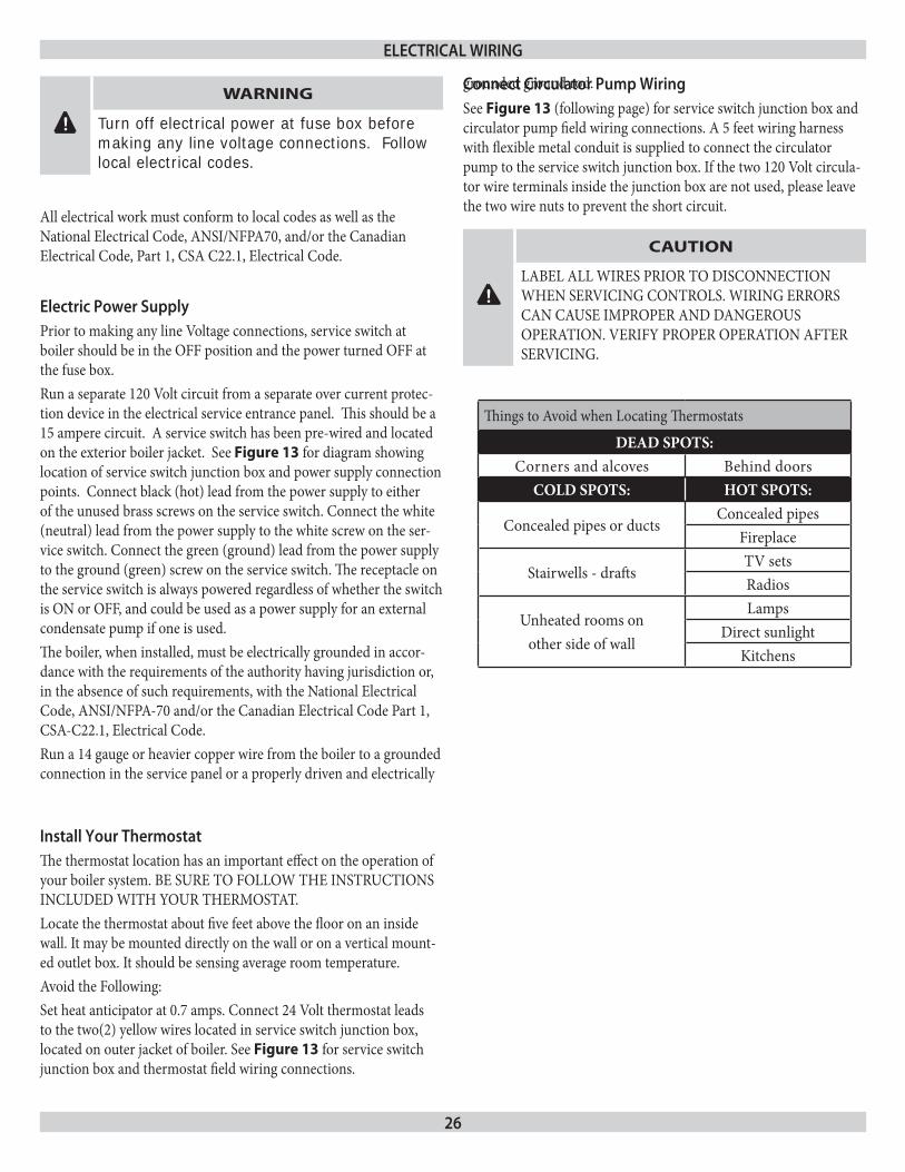
electric power supplyPrior to making any line Voltage connections, service switch at boiler should be in the OFF position and the power turned OFF at the fuse box.Run a separate 120 Volt circuit from a separate over current protec-tion device in the electrical service entrance panel. This should be a 15 ampere circuit. A service switch has been pre-wired and located on the exterior boiler jacket. See Figure 13 for diagram showing location of service switch junction box and power supply connection points. Connect black (hot) lead from the power supply to either of the unused brass screws on the service switch. Connect the white (neutral) lead from the power supply to the white screw on the ser-vice switch. Connect the green (ground) lead from the power supply to the ground (green) screw on the service switch. The receptacle on the service switch is always powered regardless of whether the switch is ON or OFF, and could be used as a power supply for an external condensate pump if one is used.The boiler, when installed, must be electrically grounded in accor-dance with the requirements of the authority having jurisdiction or, in the absence of such requirements, with the National Electrical Code, ANSI/NFPA-70 and/or the Canadian Electrical Code Part 1, CSA-C22.1, Electrical Code.Run a 14 gauge or heavier copper wire from the boiler to a grounded connection in the service panel or a properly driven and electrically
grounded ground rod.
eleCTriCal Wiring
install your ThermostatThe thermostat location has an important effect on the operation of your boiler system. BE SURE TO FOLLOW THE INSTRUCTIONS INCLUDED WITH YOUR THERMOSTAT.Locate the thermostat about five feet above the floor on an inside wall. It may be mounted directly on the wall or on a vertical mount-ed outlet box. It should be sensing average room temperature.Avoid the Following:Set heat anticipator at 0.7 amps. Connect 24 Volt thermostat leads to the two(2) yellow wires located in service switch junction box, located on outer jacket of boiler. See Figure 13 for service switch junction box and thermostat field wiring connections.
Things to Avoid when Locating Thermostats
DEAD SPOTS:Corners and alcoves Behind doors
COLD SPOTS: HOT SPOTS:
Concealed pipes or ductsConcealed pipes
Fireplace
Stairwells - draftsTV setsRadios
Unheated rooms onother side of wall
LampsDirect sunlight
Kitchens
!
CAUTION
LABEL ALL WIRES PRIOR TO DISCONNECTION WHEN SERVICING CONTROLS. WIRING ERRORS CAN CAUSE IMPROPER AND DANGEROUS OPERATION. VERIFY PROPER OPERATION AFTER SERVICING.
Connect Circulator pump WiringSee Figure 13 (following page) for service switch junction box and circulator pump field wiring connections. A 5 feet wiring harness with flexible metal conduit is supplied to connect the circulator pump to the service switch junction box. If the two 120 Volt circula-tor wire terminals inside the junction box are not used, please leave the two wire nuts to prevent the short circuit.
27
figure 13 - field Wiring Connections
eleCTriCal Wiring
28
W
BK12
0VA
C
VAC 1
WBK
CN7 R R
CN1
CN3
120V
AC
12
3
CN4
12
34
12
3
12
34321
47
58
69
1 2
CH2
21
13
54
YY
Y
Y
G
21
MV
3
CN9
MV
2
Y
Y
V
VBR
BR
PUR
BK
BKW
W
PUR
PUR
PUR
21
WR
*
CAST
ING
TEMP
ERAT
URE
SAFE
TY S
WITC
H (M
ANUA
L RES
ET)
1013
-10 IN
TEGR
ATED
BOI
LER
CONT
ROL
24V
THER
MOST
AT
CN6
CONT
ROL
PURG
EPO
WER
VALV
E/FL
AME
IGNI
TER
DIAG
NOST
IC
R R R G
120 V
AC60
HZ
1Ø
DRAF
T IND
UCER
CIRC
ULAT
OR
CN5
CIRC
ULAT
OR
DRAF
T IND
UCER
CN10
CONT
ROL
TRAN
SFOR
MER
AT14
0812
97
HOT S
URFA
CEIG
NITE
RIG
NITE
RCN
12
IGNI
TER
COLO
R DE
SIGNA
TION
W =
WHI
TEBK
= BL
ACK
Y = Y
ELLO
WG
= GRE
ENR
= RED
V =
VIOL
ETBR
= BR
OWN
PUR
=PUP
PLE
24 V
OLT W
IRIN
G
24 V
OLT F
IELD
WIR
ING
120 V
OLT W
IRIN
G12
0 VOL
T FIE
LD W
IRIN
GIN
DUCE
R
GAS
VALV
E
BLOW
ER TE
MPER
ATUR
ESA
FETY
SW
ITCH
DIFF
ERRE
NTIA
L AIR
PRES
SURE
SW
ITCH
(N.O
.)
HI LI
MIT
AQUA
STAT
CONT
ROL
24 VA
CTR
ANSF
ORME
R
HOT
NEUT
RAL
GRIU
ND
TRAN
SFOR
MER
PRIM
ARY
1PO
WER
SUP
PLY.
PROV
IDE
DISC
ONNE
CT M
EANS
AND
OVER
LODE
PRO
TECT
ION
AS R
EQUI
RED
USE
ONLY
COP
PER
WIR
E BE
TWEE
NDI
SCON
NECT
AND
THE
UNIT.
NOTE
: "CN"
LABE
L REF
EREN
CE
LOC
ATIO
N OF
CON
NECT
OR P
LUG
B
ETW
EEN
SCHE
MATIC
AND
LADD
ER
DIA
GRAM
.
24
PUMP
INDI
CATO
R LIG
HTS
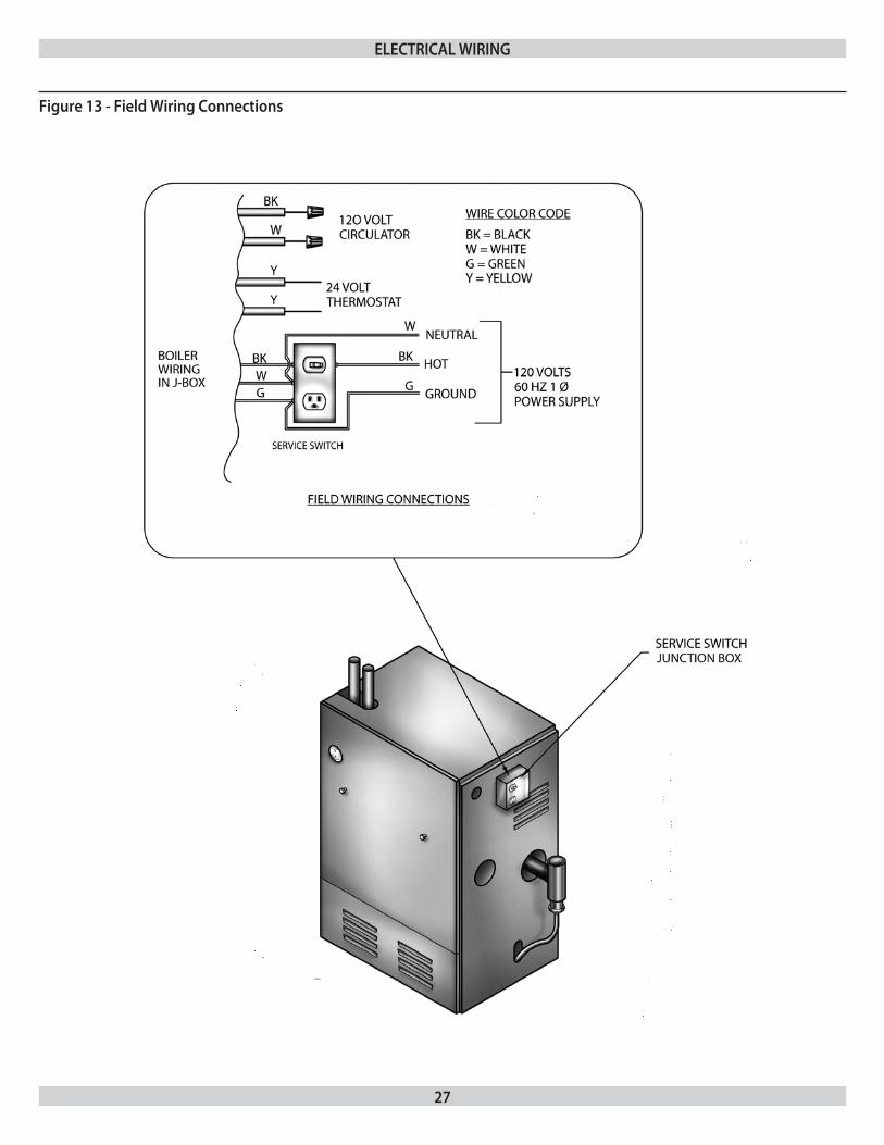
figure 14 - d - schematic Wiring diagram
eleCTriCal Wiring
If any of the original wire as supplied with this appliance must be replaced, it must be replaced with type 150°C Thermoplastic wire or its equivalent
29
DRAFT INDUCER
CASTING TEMPERATURE
AQUASTATCONTROL
MICROPROCESSORELECTRONIC
LOGIC & TIMERS
INDICATOR
VALVEIGNITERPURGEPOWER
5K4K3K2K1K
P3-7W
SAFETY SWITCH
TRANSFORMER
RP3-4
P3-6P3-3
4K1 3K1
P2-1P1-1
P1-3
P2-224
120
P3-1
L1HOT L2
P7-2
2K1
CIRCULATOR MOTOR1K1
5K1 P6-1 P6-2 5K2HOT SURFACE IGNITER
POWER SUPPLY
THERMOSTAT
1
1 POWER SUPPLY. PROVIDE
REQUIRED USE ONLY COPPER
DIFFERENTIAL AIR
P3-9HIGH LIMIT
(MANUAL RESET)
PRESSURE SWITCH
4 5
13
VR8205A
P12-1 P12-2
LOCATION OF CONNECTOR PLUGBETWEEN SCHEMATIC AND
BLK WHT
AND THE UNIT
RECEPTACLE IS LIVE WHEN* CAUTION:
*
ON/OFF SWITCH
1
2
3
1
P10-2
BOILER SWITCH IS OFF
LADDER DIAGRAM
NOTE: "P" LABEL REFERENCE
WIRE BETWEEN DISCONNECT
OVERLOAD PROTECTION ASDISCONNECT MEANS AND
120 VOLT
VAC
VAC
LIGHTS
BLOWER
SAFETY SWITCHTEMPERATURE
P3-5 P9-3 P9-2 P3-2MV MV
GAS VALVE
P4-1
P10-1
FLAME
1013-10 CONTROL
REFERENCES PLUG CONNECTION
P5-3
P7-1 P7-3P4-3
P5-1
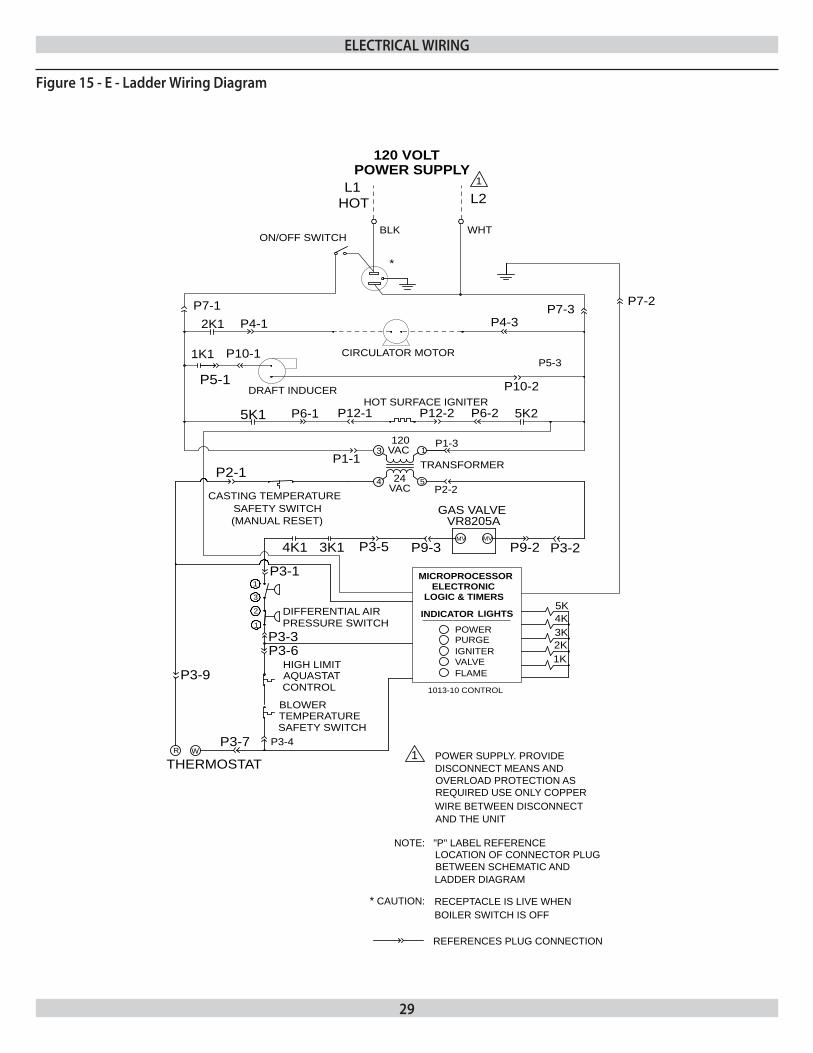
figure 15 - e - ladder Wiring diagram
eleCTriCal Wiring
30
This section provides a brief description of the key controls and accessories found in this boiler.See the Troubleshooting section (page 47 of the of this installation manual) for detailed sequences of operation and troubleshooting procedures. See the Repair Parts Manual for locations of all control components and accessories described.
integrated boiler Control (ibC)The Integrated Boiler Control (IBC) is a microprocessor based controller for a high efficiency gas boiler that monitors all safety controls and which controls the operation of the combustion air blower, circulator pump, burner, and a combination hot surface igniter/flame sensor. This controller is not intended for use with a vent damper. This controller is mounted on the control panel inside of the boiler and contains five (5) diagnostic indicator lights.
gas Control ValveThe electrically controlled 24 Volt Honeywell Model VR8205 Combination Gas Control Valve is designed to meet the requirements for use with hot surface ignition systems found in this boiler. The valve is piped to the gas/air mixer.
Hot surface igniterThe 120 Volt Hot Surface Igniter heats up to 1800 °F to initiate com-bustion of the gas in the burner. The igniter is mounted next to the burner through the gas/air mixer. The igniter also serves as a means for proving the main burner flame by flame rectification. In the event of a lack of flame signal on three (3) consecutive trials for igni-tion, the IBC will lockout. The “VALVE” and “FLAME” diagnostic indicator lamps (lamp “D” and “E” on the IBC, See Figure 16) will blink indicating the failure mode as a lack of flame signal. The IBC is manually reset from lockout by either removing and reestablishing the thermostat’s call for heat, or by turning the service switch OFF, then back ON.
High limit aquastat ControlThe High Limit Aquastat Control determines the maximum boiler water temperature and also provides a means for protecting the boiler and heating system from unsafe operating conditions which could damage the boiler. The aquastat is mounted in the ½” NPT control well and ¾”x½” bushing on the top of the front boiler section at the hot water outlet. The aquastat is tied in with the IBC and is factory set at 180 °F water temperature. The high limit setpoint is field adjustable and may be set anywhere between 100 °F and 200 °F. The field setpoint adjustment for each installation depends on heating system requirements. The aquastat automatically resets when the boiler water temperature decreases (5-30 °F adjustable differential). The differential can be adjusted with the (white) Differential Adjustment Wheel on the aquastat and gives the flexibility for boiler operation. The larger the differential, the longer the run cycle of the boiler.
NOTICE
The maximum setpoint of the Aquastat must not exceed 200 °F.
draft inducer Temperature safety switchThe Draft Inducer Temperature Safety Switch is a disc thermostat (180 °F setpoint) located on the induced draft fan outlet port. The switch protects the inducer and vent pipe from a potential high temperature condition for the discharging flue gases. This condition would typically be a result of higher aquastat setting or over firing. The temperature safety switch automatically resets when the higher aquastat setting or over firing. The temperature safety switch automatically resets when the vent temperature decreases. (15 °F switch differential).
Casting Temperature safety switchIn the event of lack of or loss of water in the boiler, the Casting Temperature Safety Switch (300 °F setpoint) installed on the top of the aluminum boiler section shuts off the boiler by shutting off power to the Integrated Boiler Control (IBC) and causes the Power Indicator Light to go out. This fault requires manual reset of the casting temperature safety switch to restart the boiler. Verify that the boiler is properly filled with water before resetting this switch. WARNING-Never run cold water into a hot empty boiler.
differential pressure air proving switch/blocked Vent safety shutoffAll 90 Series Hot Water Boilers come equipped with either one (100 Series) or two (200 Series) diaphragm-type differential pressure switches. The differential pressure switch monitors air flow by sensing the differential pressure measured in inches of water (” w.c.). The pressure switch contacts close when the draft inducer is running. The closed switch proves there is adequate air flow for combustion. The pressure switch shuts off the main burner if the differential pressure is inadequate due to a blocked vent pipe, a blocked air intake, blocked boiler sections, or a blocked draft inducer. After five (5) minutes of lack of adequate differential pressure, the IBC will lock out and the “Purge” indicator light will blink, indicating a failure to prove adequate combustion air flow or flue gas flow. The IBC will be automatically reset after fifteen (15) minutes or can be manually reset from lockout by (a) removing and reestablishing the thermostat call for heat or (b) by turning the service switch OFF and back ON again. If the boiler cannot be restored to normal operating conditions by resetting the control, contact a quallified service agency to check the heat exchanger flue-ways for blockage.
ConTrols and aCCessories
31
draft inducerThe draft inducer (blower) provides a means for pulling combustion air into and through the mixer, the burner, the flue ways of the cast aluminum boiler sections and the flue adapter before being discharged through the vent piping to the outdoors. See applicable sections for proper sizing and installation of combustion air and vent piping in this manual.
Circulator pumpEvery forced hot water system requires at least one circulating pump. The circulating pump imparts the necessary energy to move the water through the closed loop supply and return piping systems, terminal heating equipment (i.e. finned tube radiators, etc.) and back through the boiler for reheating. To provide the required hot water flow rates, the circulator pump must be properly sized to overcome frictional losses (usually measured in feet of water, also referred to as “pump head loss”) of the supply and return piping systems and boiler. The circulator pump is furnished in a carton within the boiler cabinet for a single zone or zone valve controlled heating system and should be correctly located on the downstream (i.e., pumping away) side of the expansion tank. For a pump controlled system (where there is a circulator for each zone) the circulator provided with the boiler can work for one zone. For more details on piping and circulators, see Near Boiler Piping section (page 12 of this manual).
drain ValveThe manual drain valve provides a means of draining the water in the heating system, including the boiler and hot water supply and return piping systems installed above the drain valve. This drain valve is installed in the ¾” tapping at the bottom of the front boiler section. Any piping installed below the elevation of this drain valve will require additional drain valves to be installed at low points in the piping systems in order to drain the entire system.
a.s.m.e. rated pressure relief ValveEach boiler must have a properly sized and installed American Society of Mechanical Engineers rated pressure relief valve. Water expands as it is heated by the burner/boiler sections. If there is no place for the water to expand its volume, (i.e. a properly sized and properly functioning expansion tank) pressure on the inside of the boiler and heating system will increase. The furnished relief valve will automatically open at 30 psig pressure to relieve the strain on the boiler and heating system from the increasing pressure. The pressure relief valve discharge must be piped with piping same size as the valve discharge opening to an open drain, tub or sink, or other suitable drainage point not subject to freezing, in accordance with A.S.M.E. specifications. Failure to provide the pressure relief valve with piping as herein described may cause water damage and/or serious bodily injury. The boiler manufacturer is not responsible for any water damage or personal injury.
blocked Vent safety shutoffThis boiler is equipped with a blocked vent safety shutoff means, which shuts off main burner gas in the event that the flow of combustion products through the flueways is reduced. In the event of blocked flueways, enough air will not be available to support combustion, and the S9301 Integrated Boiler Control (IBC) will lockout due to loss of adequate air flow (after 3 trials for ignition). The “PURGE” diagnostic indicator lamp (lamp “B” on the IBC, see Figure 16) will blink indicating the failure mode as a lack of adequate air flow. The IBC is manually reset from lockout by either removing and re-establishing the thermostat’s call for heat, or by turning the service switch OFF, then back ON. If the boiler cannot be restored to normal operating condition by resetting the control, contact a qualified service agency to check heat exchanger flueways for blockage.
external Condensate pump (optional) For installations where there is no floor drain or other appropriate drainage receptacle available to receive condensate from the boiler, an external float activated condensate pump with integral sump is required. This unit can be installed to pump the condensate to a remote tie in point to a sanitary sewer system. For this application, the boiler must be installed so that proper pitch of piping to the external condensate reservoir (sump) can be accomplished. Use wood frame or blocks to raise boiler as required for proper installation.
ConTrols and aCCessories
32
When filling the boiler water is the preferred heating solution. Most potable water supplies may be used to charge and re-fill provided the chlorine and chloride ions levels are less than 100 ppm. Antifreeze may be used in most applications provided all of the fol-lowing conditions are met:
Unless a strict schedule of sampling, analysis and maintenance 1. of the antifreeze solution is followed, the boiler must be piped as a primary loop connected to secondary loop as shown in the Piping & Wiring Diagram Appendix. Failure to perform regular maintenance to the antifreeze manufacturer’s instructions will result in damage to the heat exchanger and the voiding of boiler warranty.Only the antifreeze manufacturers listed below are selected.2.
At installation of a new or replacement boiler and at least on 3. an annual basis the system antifreeze must be analyzed by the antifreeze supplier or their recommended laboratory.Adjustments to the system antifreeze must be made according 4. to the antifreeze manufacturers recommendations using only their recommended products.All existing systems MUST be flushed of ALL old system fluid. 5. Failure to do so may void the boiler warranty if evidence of im-proper flushing is revealed. Consult with your heating profes-sional for recommendations.
piping recommendationsSystem leaks may not always be visible. An unseen system leak will become obvious if boiler pressure decreases when make up valve is closed.All system leaks must be repaired immediately. Constant introduc-tion of make up water will introduce dissolved oxygen, resulting in accelerated boiler corrosion.It is recommended that Primary/Secondary piping be used with any of the recommended antifreeze solutions found in this manual. See the Piping & Wiring Diagram Appendix.
Water ChemistryThis boiler is designed for a closed loop hydronic heat system ONLY! This boiler is not suitable for natural gravity type installations, or any other open type system.System fluid pH must be maintained between 7.0 and 8.0.Maintain water hardness below 7 grains hardness.Filling with chlorinated fresh water should be acceptable since drinking water chlorine levels are typically less than 5 ppm. Do not fill boiler with water containing chlorine and chloride ions levels greater than 100 ppm.Do not use inhibitors or other additives that are not specifically ap-proved by the antifreeze manufacturer for this product.Consult the antifreeze manufacturer if any of the above are outside the stated ranges.
Cleaning the Hydronic systemIMPORTANT: Do not mix different manufacturers’ products. Doing so will void the warranty of the boiler.Consideration MUST be given to cleaning the heating system, particularly in retrofit situations where a new boiler with an aluminum heat exchanger is being installed in an existing piping system.All existing systems must be cleaned and flushed according to the antifreeze manufacturer’s recommendations. Systems that have antifreeze that is not recommended by the boiler manufacturer must be completely flushed to ensure no unapproved antifreeze remains according to the recommended antifreeze manufactures recommendations. Evidence of an alternate antifreeze in the system may void the boiler warranty.In older systems obviously discolored, murky or dirty water; or a pH reading outside the boiler manufacturer’s stated acceptable range (pH 7.0 to 8.0) are indications that the system should be cleaned or treated.
Measure total capacity of the system including the piping, 1. tanks, boiler, collector plates, etc. The most accurate method of measuring fluid capacity is to fill the system and then completely drain it, volumetrically measuring the fluid drained.Thoroughly flush the system with clean water to remove any 2. sediment or contaminants. Sludge and iron oxide deposits can cause rapid breakdown of inhibitors.Cleaning fluid – Flushing with clean water is preferred. If 3. cleaning fluid is used, only use cleaner specifically approved for use with aluminum boilers. Use only cleaning fluids and the procedure recommended by the antifreeze manufacturer.
freeze protectionAluminum Safe Antifreeze, Treatments and Additive Guidelines:Antifreeze, if required, must be one of the antifreeze manufacturers listed in this manual. See the “Recommended Aluminum Antifreeze & Inhibitor Suppliers” section of this manual for a list of boiler manufacturer approved products.Always clean system prior to using antifreeze, refer to the Cleaning the Hydronic System section of this manual for details.Only use the antifreeze manufacturers’ products outlined in this document.Use of antifreeze must be in accordance with local plumbing codes.Dispose of old antifreeze and boiler system water in accordance with local authorities.Antifreeze will raise the pH of the hydronic solution in a heating system above the recommended level due to the corrosion inhibitors in the antifreeze. The solution must be treated to maintain a pH within the boiler manufacturer’s recommended level to avoid damage to the heat exchanger. Follow antifreeze manufacturer’s instructions for details on how to adjust the pH.
WaTer TreaTmenT & freeZe proTeCTion
33
WaTer TreaTmenT & freeZe proTeCTion
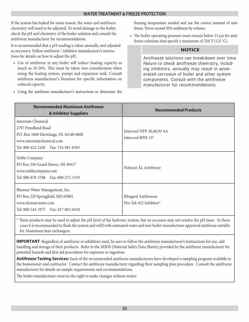
If the system has leaked for some reason, the water and antifreeze chemistry will need to be adjusted. To avoid damage to the boiler, check the pH and chemistry of the boiler solution and consult the antifreeze manufacturer for recommendations.It is recommended that a pH reading is taken annually, and adjusted as necessary. Follow antifreeze / inhibitor manufacturer’s instruc-tions for details on how to adjust the pH.
Use of antifreeze in any boiler will reduce heating capacity as •much as 10-20%. This must be taken into consideration when sizing the heating system, pumps and expansion tank. Consult antifreeze manufacturer’s literature for specific information on reduced capacity.
Using the antifreeze manufacturer’s instructions to determine the •
freezing temperature needed and use the correct amount of anti-freeze. Never exceed 50% antifreeze by volume.
The boiler operating pressure must remain below 15 psi for anti-•freeze solutions that specify a maximum of 250˚F (121˚C).
NOTICE
Antifreeze solutions can breakdown over time. Failure to check antifreeze chemistry, includ-ing inhibitors, annually may result in accel-erated corrosion of boiler and other system components. consult with the antifreeze manufacturer for recommendations.
Recommended Aluminum Antifreeze
& Inhibitor SuppliersRecommended Products
Interstate Chemical2797 Freedland RoadP.O. Box 1600 Hermitage, PA 16148-0600www.interstatechemical.comTel: 800-422-2436 Fax: 724-981-8383
Intercool NFP-30,40,50 AAIntercool RPH-15*
Noble CompanyPO Box 350 Grand Haven, MI 49417www.noblecompany.comTel: 800-878-5788 Fax: 800-272-1519
Noburst AL Antifreeze
Rhomar Water Management, Inc.PO Box 229 Springfield, MO 65801www.rhomarwater.comTel: 800-543-5975 Fax: 417-862-6410
Rhogard Antifreeeze Pro-Tek 922 Inhibitor*
* These products may be used to adjust the pH level of the hydronic system, but on occasion may not resolve the pH issue. In these cases it is recommended to flush the system and refill with untreated water and new boiler manufacturer approved antifreeze suitable for Aluminum heat exchangers.
IMPORTANT: Regardless of antifreeze or inhibitors used, be sure to follow the antifreeze manufacturer’s instructions for use, safe handling and storage of their products. Refer to the MSDS (Material Safety Data Sheets) provided by the antifreeze manufacturer for potential hazards and first aid procedures for exposure or ingestion.Antifreeze Testing Services: Each of the recommended antifreeze manufacturers have developed a sampling program available to the homeowner and contractor. Contact the antifreeze manufacturer regarding their sampling plan procedure. Consult the antifreeze manufacturer for details on sample requirements and recommendations.The boiler manufacturer reserves the right to make changes without notice.
34
filling boiler With Water and purging air for systems With diaphragm Type expansion TanksRefer to the appropriate diagrams in Section VII, “Near Boiler Pip-ing,” for more information.
Close all zone service valves on the supply and return piping. 1. Open the feed valve and fill boiler with water. Make sure air vent is open. Hold relief valve open until water runs air free for five seconds to rapidly bleed air from boiler, then let the relief valve snap shut.Open the zone service valve on the supply pipe for the first 2. zone. Open the purge valve on the first zone. Feed water will fill the zone, pushing air out the purge valve. Close the purge valve when the water runs air free. Close the zone service valve.Repeat step 2 for all remaining zones.3. Open all service valves. Any air remaining trapped in the return 4. lines between the service valves and the boiler will be pushed towards the air vent when the boiler is placed in operation.Inspect piping system. Repair any leaks immediately.5.
purging air for systems With Conventional Closed Type expansion Tanks:Refer to the appropriate diagrams in Section VII, “Near Boiler Piping,” for more information.
Close all zone service valves on the supply and return piping 1. and close the expansion tank service valve. Drain expansion tank. Open the feed valve and fill boiler with water. Hold relief valve open until water runs air free for five seconds to rapidly bleed air from boiler, then let the relief valve snap shut.Open the zone service valve on the supply pipe for the first 2. zone. Open the purge valve on the first zone. Feed water will fill the zone, pushing air out the purge valve. Close the purge valve when the water runs air free. Close the zone service valve.Repeat step 2 for all remaining zones.3. Open the expansion tank service valve and the tank vent. Fill 4. the tank to the proper level and close the tank vent. Remove the handle from the expansion tank service valve so the homeowner doesn’t accidentally close it.Open all service valves. Any air remaining trapped in the return 5. lines between the service valves and the boiler will be pushed towards the expansion tank when the boiler is placed in opera-tion.Inspect piping system. Repair any leaks immediately.6.
NOTICE
DO NOT use stop leak compounds. Leaks in threaded connections in the aluminum boiler sections must be repaired immediately. Aluminum threads will not seal themselves.
placing boiler in operation
!
WARNING
If you do not follow these instructions exactly, a fire or explosion may result causing property damage, personal injury or loss of life.
This appliance is equipped with an ignition device which A. automatically lights the pilot. Do not try to light the pilot by hand.BEFORE OPERATING smell all around the appliance area B. for gas. Be sure to smell next to the floor because some gas is heavier than air and will settle on the floor.
What To Do If You Smell Gas
Do not try to light any appliance.•
Do not touch any electrical switch; do not use any phone in •your building.
Immediately call your gas supplier from a neighbor’s •phone. Follow the gas supplier’s instructions.
If you cannot reach your gas supplier, call the fire depart-•ment.Use only your hand to move the system control switch. C. Never use tools. If the switch will not move by hand, don’t try to repair it, call a qualified service technician. Force or attempted repair may result in a fire or explosion.Do not use this appliance if any part has been under water. D. Immediately call a qualified service technician to inspect the appliance and to replace any part of the control system and any gas control which has been under water.
sTarT up
35
Safe lighting and other performance criteria were met with the gas manifold and control assembly provided on the boiler when the boiler underwent tests specified in ANSI Z21.13-latest revision.
STOP! Read the safety information above on this label.1.
Set thermostat to lowest setting.2.
Turn off all electric power to the appliance.3.
This appliance is equipped with an ignition device which 4. automatically lights the burner. DO NOT try to light the burner by hand.Remove the front jacket panel.5.
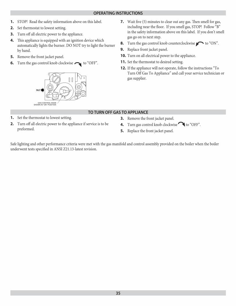
Turn the gas control knob clockwise 6. to “OFF”.
Wait five (5) minutes to clear out any gas. Then smell for gas, 7. including near the floor. If you smell gas, STOP! Follow “B” in the safety information above on this label. If you don’t smell gas go on to next step.Turn the gas control knob counterclockwise 8. to “ON”.Replace front jacket panel.9.
Turn on all electrical power to the appliance.10.
Set the thermostat to desired setting.11.
If the appliance will not operate, follow the instructions “To 12. Turn Off Gas To Appliance” and call your service technician or gas supplier.
OFF
ONINLET
GAS CONTROL KNOBSHOWN IN "ON" POSITION
Set the thermostat to lowest setting.1.
Turn off all electric power to the appliance if service is to be 2. preformed.
Remove the front jacket panel.3.
Turn gas control knob clockwise 4. to “OFF”.Replace the front jacket panel. 5.
operaTing insTruCTions
To Turn off gas To applianCe
36
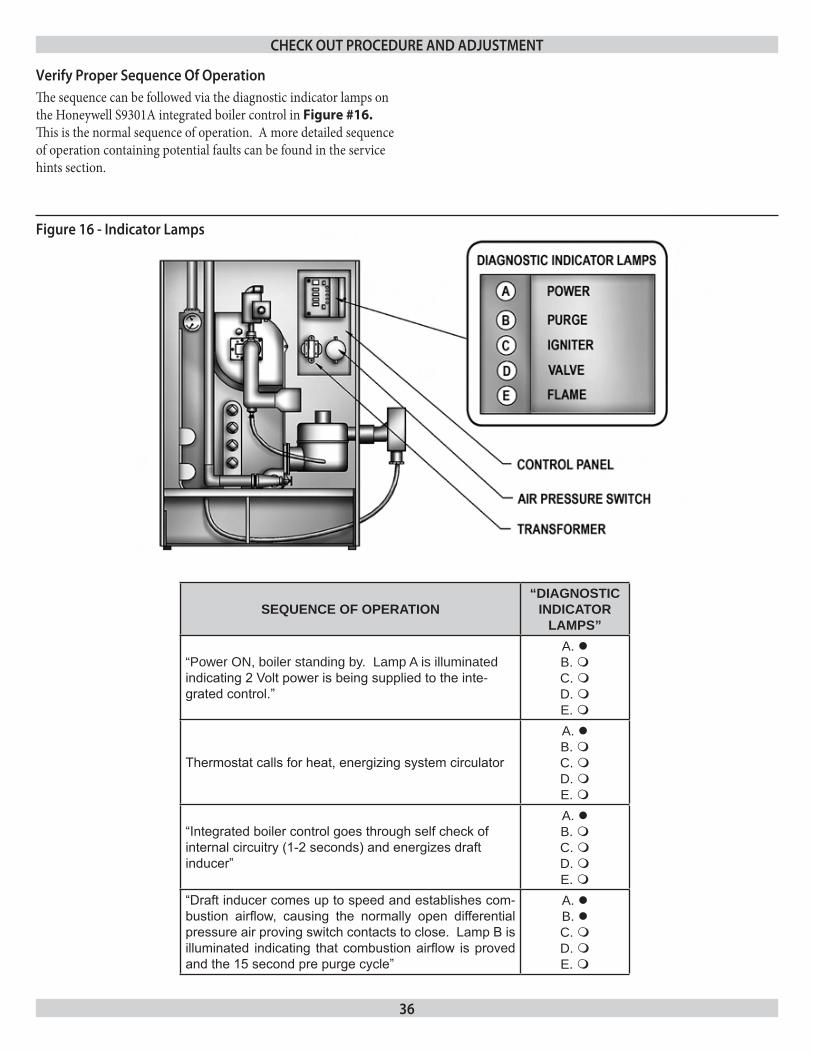
Verify proper sequence of operationThe sequence can be followed via the diagnostic indicator lamps on the Honeywell S9301A integrated boiler control in Figure #16. This is the normal sequence of operation. A more detailed sequence of operation containing potential faults can be found in the service hints section.
SEQUENCE OF OPERATION“DIAGNOSTIC
INDICATOR LAMPS”
“Power ON, boiler standing by. Lamp A is illuminated indicating 2 Volt power is being supplied to the inte-grated control.”
A. B. C. D. E.
Thermostat calls for heat, energizing system circulator
A. B. C. D. E.
“Integrated boiler control goes through self check of internal circuitry (1-2 seconds) and energizes draft inducer”
A. B. C. D. E.
“Draft inducer comes up to speed and establishes com-bustion airflow, causing the normally open differential pressure air proving switch contacts to close. Lamp B is illuminated indicating that combustion airflow is proved and the 15 second pre purge cycle”
A. B. C. D. E.
figure 16 - indicator lamps
CHeCk ouT proCedure and adjusTmenT
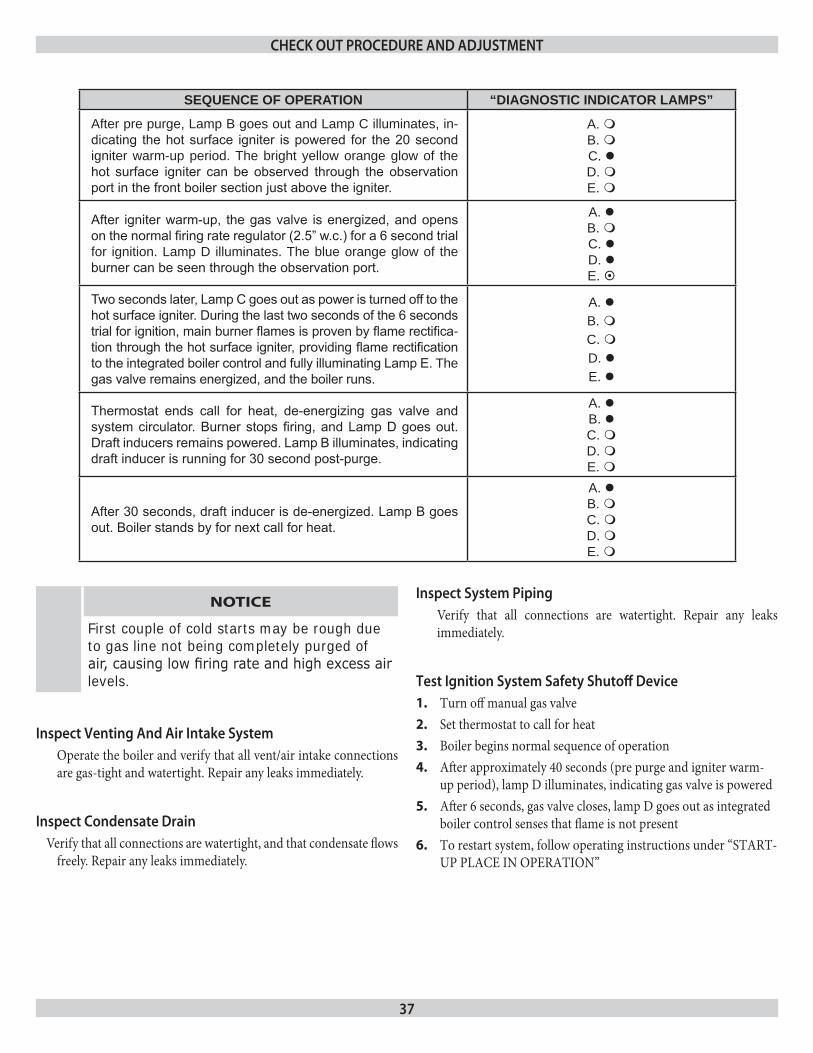
37
NOTICE
First couple of cold starts may be rough due to gas line not being completely purged of air, causing low firing rate and high excess air levels.
inspect Venting and air intake systemOperate the boiler and verify that all vent/air intake connections are gas-tight and watertight. Repair any leaks immediately.
inspect Condensate drain Verify that all connections are watertight, and that condensate flows
freely. Repair any leaks immediately.
inspect system pipingVerify that all connections are watertight. Repair any leaks immediately.
Test ignition system safety shutoff deviceTurn off manual gas valve1.
Set thermostat to call for heat2.
Boiler begins normal sequence of operation3.
After approximately 40 seconds (pre purge and igniter warm-4. up period), lamp D illuminates, indicating gas valve is poweredAfter 6 seconds, gas valve closes, lamp D goes out as integrated 5. boiler control senses that flame is not presentTo restart system, follow operating instructions under “START-6. UP PLACE IN OPERATION”
SEQUENCE OF OPERATION “DIAGNOSTIC INDICATOR LAMPS”
After pre purge, Lamp B goes out and Lamp C illuminates, in-dicating the hot surface igniter is powered for the 20 second igniter warm-up period. The bright yellow orange glow of the hot surface igniter can be observed through the observation port in the front boiler section just above the igniter.
A. B. C. D. E.
After igniter warm-up, the gas valve is energized, and opens on the normal firing rate regulator (2.5” w.c.) for a 6 second trial for ignition. Lamp D illuminates. The blue orange glow of the burner can be seen through the observation port.
A. B. C. D. E.
Two seconds later, Lamp C goes out as power is turned off to the hot surface igniter. During the last two seconds of the 6 seconds trial for ignition, main burner flames is proven by flame rectifica-tion through the hot surface igniter, providing flame rectification to the integrated boiler control and fully illuminating Lamp E. The gas valve remains energized, and the boiler runs.
A. B. C. D. E.
Thermostat ends call for heat, de-energizing gas valve and system circulator. Burner stops firing, and Lamp D goes out. Draft inducers remains powered. Lamp B illuminates, indicating draft inducer is running for 30 second post-purge.
A. B. C. D. E.
After 30 seconds, draft inducer is de-energized. Lamp B goes out. Boiler stands by for next call for heat.
A. B. C. D. E.
CHeCk ouT proCedure and adjusTmenT
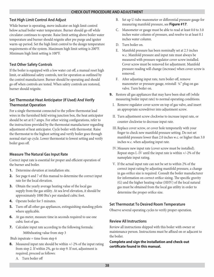
38
Test High limit Control and adjustWhile burner is operating, move indicator on high limit control below actual boiler water temperature. Burner should go off while circulator continues to operate. Raise limit setting above boiler water temperature and burner should reignite after pre purge and igniter warm-up period. Set the high limit control to the design temperature requirements of the system. Maximum high limit setting is 200°F. Minimum high limit setting is 100°F.
Test other safety ControlsIf the boiler is equipped with a low water cut off, a manual reset high limit, or additional safety controls, test for operation as outlined by the control manufacturer. Burner should be operating and should go off when controls are tested. When safety controls are restored, burner should reignite.
set Thermostat Heat anticipator (if used) and Verify Thermostat operationFor a single thermostat connected to the yellow thermostat lead wires in the furnished field wiring junction box, the heat anticipator should be set at 0.7 amps. For other wiring configurations, refer to the instructions provided by the thermostat manufacturer regarding adjustment of heat anticipator. Cycle boiler with thermostat. Raise the thermostat to the highest setting and verify boiler goes through normal start up cycle. Lower thermostat to lowest setting and verify boiler goes off.
measure The natural gas input rateCorrect input rate is essential for proper and efficient operation of the burner and boiler.
Determine elevation at installation site.1.
See page 6 and 7 of this manual to determine the correct input 2. rate for the local elevation.Obtain the yearly average heating value of the local gas 3. supply from the gas utility. At sea level elevation, it should be approximately 1000 Btu’s per standard cubic foot.Operate boiler for 5 minutes.4.
Turn off all other gas appliances, extinguishing standing pilots 5. where applicable.At gas meter, measure time in seconds required to use one 6. cubic foot of gas.Calculate input rate according to the following formula:7.
3600xheating value from step 3 Btuh inputrate = time from step 6
Measured input rate should be within +/-2% of the input rating 8. from step 2. If within 2%, go to step 9. If not, adjustment is required, proceed as follows:
Turn boiler offA.
Set up U-tube manometer or differential pressure gauge for B. measuring manifold pressure, see Figure #17.Manometer or gauge must be able to read at least 0.0 to 3.0 C. inches water column of pressure, and resolve to at least 0.1 inches water column.Turn boiler on.D. Manifold pressure has been nominally set at 2.5 inches E. w.c. Manifold pressure and input rate must always be measured with pressure regulator cover screw installed. Cover screw must be removed for adjustment. Manifold pressure reading will change (increase) when cover screw is removed.After adjusting input rate, turn boiler off, remove F. manometer or pressure gauge, reinstall ⅛” plug on gas valve. Turn boiler on.
Restore all gas appliances that may have been shut off (while 9. measuring boiler input rate) to normal operating conditions.
Remove regulator cover screw on top of gas valve, and insert I. an appropriate screwdriver into adjustment screw.
Turn adjustment screw clockwise to increase input rate, or II. counter clockwise to decrease input rate.
Replace cover screw, or cover hole temporarily with your III. finger to check new manifold pressure setting. Do not set manifold pressure lower than 2.0 inches w.c. or higher than 3.0 inches w.c. when adjusting input rate.
Measure new input rate (cover screw must be installed). IV. Repeat steps I.-IV until the input rate is within +/-2% of the nameplate input rating.
If the actual input rate can not be set to within 2% of the V. correct input rating by adjusting manifold pressure, a change in gas orifice size is required. Consult the boiler manufacturer for information on correct orifice sizing. The specific gravity (G) and the higher heating value (HHV) of the local natural gas must be obtained from the local gas utility in order to determine the proper orifice size.
set Thermostat To desired room TemperatureObserve several operating cycles to verify proper operation.
review all instructionsReview all instructions shipped with this boiler with owner or maintenance person. Instructions must be affixed on or adjacent to the boiler.Complete and sign the installation and check-out certificate found in this manual.
CHeCk ouT proCedure and adjusTmenT
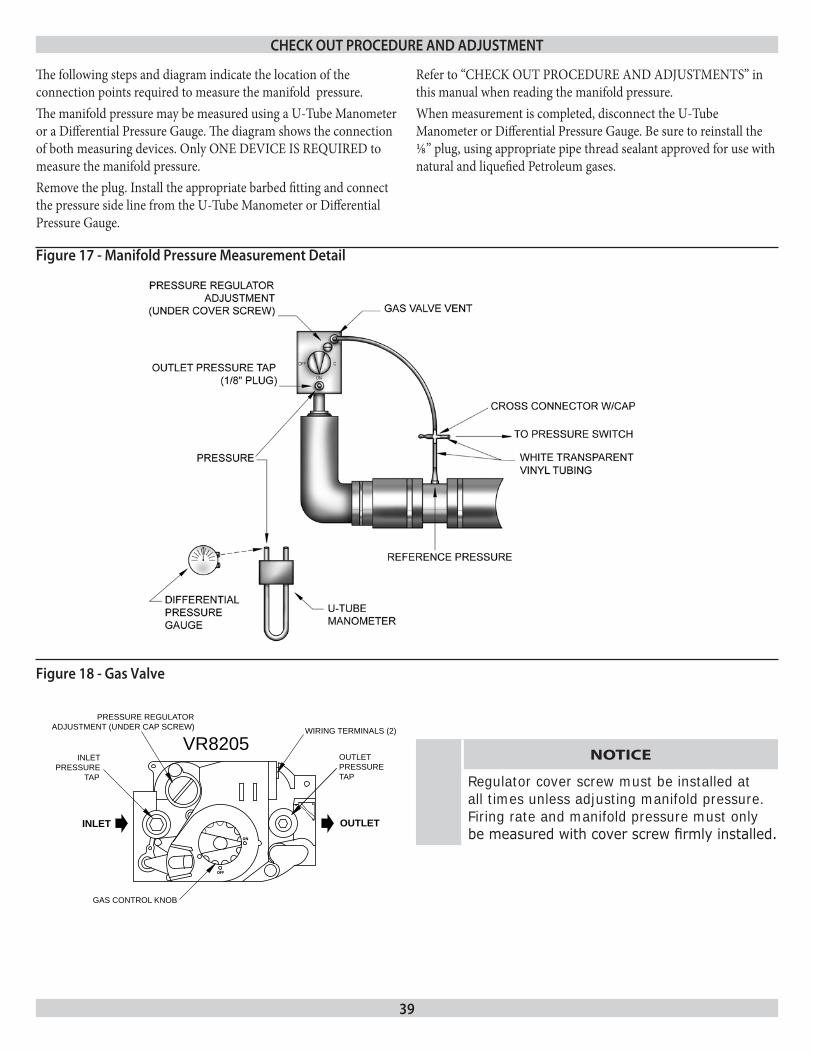
39
The following steps and diagram indicate the location of the connection points required to measure the manifold pressure.The manifold pressure may be measured using a U-Tube Manometer or a Differential Pressure Gauge. The diagram shows the connection of both measuring devices. Only ONE DEVICE IS REQUIRED to measure the manifold pressure.Remove the plug. Install the appropriate barbed fitting and connect the pressure side line from the U-Tube Manometer or Differential Pressure Gauge.
OFF
ON
INLET OUTLET
GAS CONTROL KNOB
PRESSURE REGULATOR ADJUSTMENT (UNDER CAP SCREW)
INLET PRESSURE
TAP
VR8205 WIRING TERMINALS (2)
OUTLET PRESSURE TAP
figure 17 - manifold pressure measurement detail
figure 18 - gas Valve
CHeCk ouT proCedure and adjusTmenT
NOTICE
Regulator cover screw must be installed at all times unless adjusting manifold pressure. Firing rate and manifold pressure must only be measured with cover screw firmly installed.
Refer to “CHECK OUT PROCEDURE AND ADJUSTMENTS” in this manual when reading the manifold pressure.When measurement is completed, disconnect the U-Tube Manometer or Differential Pressure Gauge. Be sure to reinstall the ⅛” plug, using appropriate pipe thread sealant approved for use with natural and liquefied Petroleum gases.
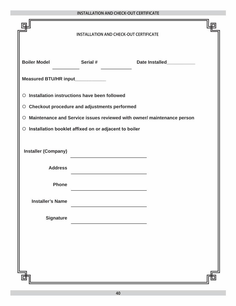
40
insTallaTion and CHeCk-ouT CerTifiCaTe
Boiler Model Serial # Date Installed___________
Measured BTU/HR input____________
Installation instructions have been followed
Checkout procedure and adjustments performed
Maintenance and Service issues reviewed with owner/ maintenance person
Installation booklet affixed on or adjacent to boiler
Installer (Company)
Address
Phone
Installer’s Name
Signature
insTallaTion and CHeCk-ouT CerTifiCaTe
41
Maintenance as outlined below can be performed by the owner unless otherwise noted.
The acidic nature of flue gasses condensing on the aluminum boiler sections will cause the formation of aluminum oxide. This oxide formation is normal, is generally uniform throughout the boiler sections, and represents a negligible mass of aluminum that is consumed by oxidation during the life of the boiler. If left unchecked, this buildup may eventually cause blockage of the flue gas passages in the boiler sections, reducing efficiency, and ultimately shutting down the boiler due to lack of combustion air flow. Regular service and maintenance by a qualified service agency must be performed to assure safe trouble free operation and maximum efficiency.
beginning of each Heating seasonAnnual service call by a qualified service agency, which 1. includes:
Examine flue passages between boiler sections, burner, A. and condensate lines, and clean if necessary following the annual examination and cleaning instructions in para graph “F” on the next page.Visually inspect venting and air intake system for proper B. function, deterioration or leakage. If the vent or air intake show any signs of deterioration or leakage, repair or replace them, immediately. Insure proper reassembly and resealing of the vent and air intake systemCheck for and remove any obstruction to the flow of C. combustion air or venting of flue gases. Check the air baffle located inside 1½” x 2” flexible coupling on the mixer, clean it if necessary and make sure to put it back. Refer to repair parts diagram of mixer and pressure switch assembly for exact location.Follow instructions for “PLACING BOILER IN D. OPERATION”.Follow instructions for” CHECK OUT PROCEDURE E. AND ADJUSTMENTS”.Visually inspect condensate drain line for proper operation F. and deterioration. Check for plugged condensate drain line.Check the silicone rubber seals between boiler sections. G. Insure that there are no leaks. Use RTV silicone rubber adhesive sealant (available in caulking gun tubes) rated for at least 400° F to replace or repair seals in locations where original seals have deteriorated.Check all gasketed joints for leakage, and tighten bolts or H. replace gaskets if necessary.Remove jacket front and top panels and check for piping I. leaks around relief valve and other fittings. Repair, if found. DO NOT use stop leak compounds.
Check that boiler area is free from combustible materials, 2. gasoline, and other flammable vapors and liquids.Circulator pump and blower motor furnished with boiler are 3. permanently lubricated from factory and require no further lubrication. Additional or non-factory supplied pumps and/or motors should be lubricated according to the pump and/or motor manufacturer’s instruction.
daily during Heating seasonCheck for and remove any obstruction to the flow of 1. combustion air or venting of flue gases.Check that boiler area is free from combustible materials, 2. gasoline, and other flammable vapors and liquids.
mainTenanCe and Cleaning
42
monthly during Heating season1. Remove jacket front and top panels and check for piping 1. leaks around relief valve and other fittings. If found, contact a qualified service agency to repair. DO NOT use stop leak compounds.2. Test relief valve. Refer to valve manufacturers instructions 2. packaged with relief valve.3. Visually inspect venting and air intake system for proper 3. function, deterioration, or leakage. If the vent or air intake show any signs of deterioration or leakage, contact a qualified service agency to repair or replace them immediately and to insure proper reassembly and resealing of the vent and air intake system.4. Visually inspect the clear vinyl condensate lines and the 4. PVC condensate drain pipe for proper operation, leakage, and deterioration. If the condensate lines or drain pipe show any signs of blockage, leakage, or deterioration contact a qualified service agency to clean, repair, or replace them immediately.5. Check the air baffle located inside 1 ½” x 2” flexible coupling, 5. clean it if necessary and make sure to put it back. Refer to repair parts diagram, mixer and pressure switch assembly.
periodically during Heating seasonWhere low water cut offs are used, a periodic inspection of the low water cut off is necessary, including flushing of float type devices. Refer to low water cut off manufacturer’s specific instructions.
end of each Heating season - annual shutdown procedureFollow instructions “TO TURN OFF GAS TO APPLIANCE”.If heating system is to remain out of service during freezing weather, and does not contain antifreeze, drain system completely. If boiler will be exposed to freezing temperatures, drain condensate lines. Otherwise, do not drain system or boiler.
annual examination and Cleaning of boiler Components
Before Servicing, turn off electrical power to boiler at service 1. switch. Close manual gas valve to turn off gas supply to boiler.
NOTICE
The following service procedures must be performed only by a qualified service agency. boiler owner should not attempt these procedures.
Cleaning Flue passages between boiler sections. 2. Any buildup of sediment or aluminum oxide (white A. powdery or flaky substance) in the flue passages must be cleaned as follows:Remove jacket front and top panels. Disconnect B. condensate drain line from the barbed fitting on the bottom of the boiler. Keep the open end of the drain line above the water level in the condensate trap to prevent the trap from draining. Disconnect pressure switch hose from barbed fitting on gas valve. Disconnect 1½ x 2” flexible coupling from air inlet. Disconnect air by-pass (½” transparent vinyl tube) from the bottom of the mixer.Remove air baffle from ½” x 2” flexible coupling and clean C. air baffle if necessary. Refer to repair parts diagram, mixer and pressure switch assembly.Confirm that manual gas valve is closed and disconnect gas D. line to gas valve at union. Disconnect wires to gas valve. and igniter.Loosen but do not remove five (5) nuts attaching mixer E. assembly to boiler. Remove two (2) igniter screws and very carefully remove the igniter. Use care when removing the igniter, it is very brittle!Remove five (5) nuts and remove mixer assembly. Remove F. burner and mixer gasket.Aluminum oxide deposits are water soluble and may be G. rinsed away with spraying or running water. Before rinsing, connect a ½” I.D. hose to the barbed fitting on the bottom of the boiler and run the hose to a bucket or drain.After rinsing, remove any remaining loosened sediment H. using a shop vacuum with a snorkel attachment.Inspect burner for any foreign matter in the flame ports or I. inside the burner. Any foreign matter should be removed by blowing with compressed air or vacuuming.Inspect interior of mixer for any signs of sediment or J. aluminum oxide and clean if necessary.
mainTenanCe and Cleaning
43
Reinstall burner and mixer gasket and position mixer K. assembly over studs. Install five (5) nuts but do not tighten. Reinstall igniter and igniter gasket and fasten with two (2) screws. Use care when installing the igniter. It is very brittle! Tighten five (5) nuts holding mixer assembly.Connect:L. Gas line to gas valve•
Condensate drain line to boiler •
Pressure switch hose to gas valve•
Air by-pass to mixer•
1 ½” x 2” flexible coupling to air inlet and make sure to put •air baffle back to correct position
Igniter wires •
Gas valve wires •
Visually inspect condensate lines leading from the boiler 3. sections and the vent tee to the condensate trap. Refer to repair parts diagrams. Any foreign material or debris that is visible in the condensate lines needs to be cleaned out as follows:
Raise condensate trap and drain condensate lines A. completely.Once the condensate trap is emptied of water, disconnect B. condensate lines from the fittings on the boiler, the vent tee, and the condensate outlet.Remove the condensate trap and run cold water through C. the condensate lines to thoroughly flush out any sediment or debris in the lines.Reinstall and connect the condensate trap, using the hose D. clamps to secure the various condensate lines to their fittings.Follow the instructions under “NEAR BOILER PIPING” E. for” filling condensate trap with water”
Inspection of the flue connector requires the following steps (Refer to 4. the repair parts diagram.)
Loosen the clamp on the draft inducer end of the 2” A. flexible coupling that connects the vent tee to the draft inducer. Disconnect (unplug) wiring harness from draft inducer motor and draft inducer temperature safety switch. Remove four (4) bolts that attach draft inducer to flue connector.Remove draft inducer and gasket from top of flue B. connector.Inspect interior of flue connector. Any buildup of sediment C. or aluminum oxide on the inside surface must be cleaned. Position the draft inducer gasket and the draft inducer and fasten with four (4) screws. Be sure to connect ground wire from draft inducer motor to one of the four mounting screws.Connect wiring harness leads to the draft inducer motor D. and the draft inducer temperature safety switch.Connect the 2” flexible coupling to the draft inducer outlet.E.
mainTenanCe and Cleaning
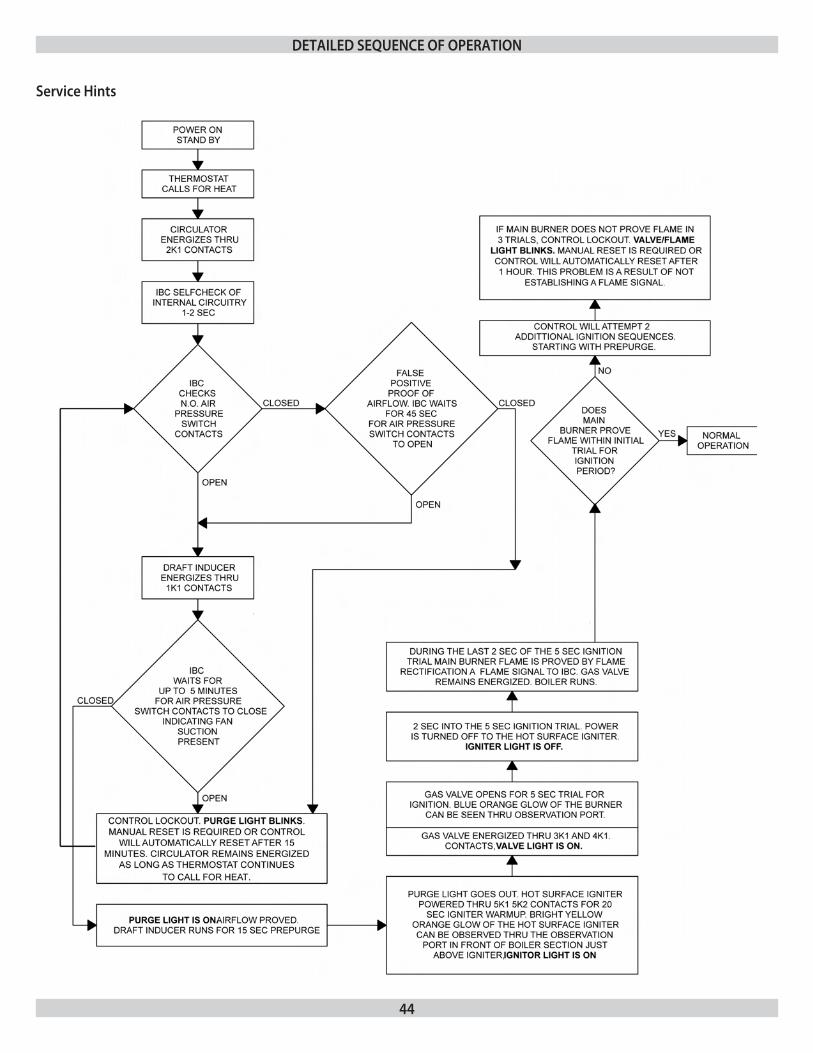
44
service Hints
deTailed sequenCe of operaTion
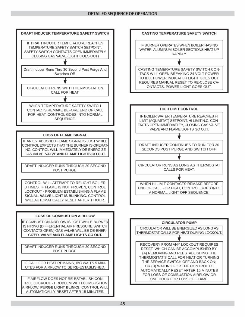
45
LOSS OF COMBUSTION AIRFLOwIF COMBUSTION AIRFLOW IS LOST WHILE BURNER IS FIRING (DIFFERENTIAL AIR PRESSURE SWITCH CONTACTS OPEN) GAS VALVE WILL BE DE-ENER-
GIzED. VALVE AND FLAME LIGHTS GO OUT.
DRAFT INDUCER RUNS THROUGH 30 SECOND POST PURGE.
IF CALL FOR HEAT REMAINS, IBC WAITS 5 MIN-UTES FOR AIRFLOW TO BE RE-ESTABLISHED.
IF AIRFLOW DOES NOT RE-ESTABLISH CON-TROL LOCkOUT - PROBLEM WITH COMBUSTION AIRFLOW. PURGE LIGHT BLINKS. CONTROL WILL
AUTOMATICALLY RESET AFTER 15 MINUTES.
LOSS OF FLAME SIGNALIF AN ESTABLISHED FLAME SIGNAL IS LOST WHILE
CONTROL EXPECTS THAT THE BURNER IS OPERAT-ING, CONTROL WILL IMMEDIATELY DE-ENERGIzE GAS VALVE. VALVE AND FLAME LIGHTS GO OUT.
DRAFT INDUCER RUNS THROUGH 30 SECOND POST PURGE.
CONTROL WILL ATTEMPT TO RELIGHT BOILER 3 TIMES. IF FLAME IS NOT PROVEN, CONTROL LOCkOUT - PROBLEM ESTABLISHING A FLAME SIGNAL. VALVE LIGHT IS BLINKING. CONTROL WILL AUTOMATICALLY RESET AFTER 1 HOUR.
CIRCULATOR PUMPCIRCULATOR WILL BE ENERGIzED AS LONG AS
THERMOSTAT CALLS FOR HEAT DURING LOCkOUT.
RECOVERY FROM ANY LOCkOUT REqUIRES RESET, WHICH CAN BE ACCOMPLISHED BY:(A) REMOVING AND REESTABLISHING THE
THERMOSTAT’S CALL FOR HEAT OR TURNINGTHE SERVICE SWITCH OFF AND BACk ON;
OR (B) WAITING FOR THE CONTROL TOAUTOMATICALLY RESET AFTER 15 MINUTESFOR LOSS OF COMBUSTION AIRFLOW OR
ONE HOUR FOR LOSS OF FLAME.
DRAFT INDUCER TEMPERATURE SAFETy SwITCH
IF DRAFT INDUCER TEMPERATURE REACHES TEMPERATURE SAFETY SWITCH SETPOINT,
SAFETY SWITCH CONTACTS OPEN IMMEDIATELY CLOSING GAS VALVE (LIGHT GOES OUT)
Draft Inducer Runs Thru 30 Second Post Purge And Switches Off.
CIRCULATOR RUNS WITH THERMOSTAT ON CALL FOR HEAT.
WHEN TERMPERATURE SAFETY SWITCH CONTACTS REMAkE BEFORE END OF CALL FOR HEAT, CONTROL GOES INTO NORMAL
SEqUENCE.
CASTING TEMPERATURE SAFETy SwITCH
IF BURNER OPERATES WHEN BOILER HAS NO WATER, ALUMINUM BOILER SECTIONS HEAT UP
RAPIDLY.
CASTING TEMERATURE SAFETY SWITCH CON-TACS WILL OPEN BREAkING 24 VOLT POWER TO IBC. POWER INDICATOR LIGHT GOES OUT. REqUIRES MANUAL RESET TO RE-CLOSE CA-
ONTACTS. POWER LIGHT GOES OUT.
HIGH LIMIT CONTROL
IF BOILER WATER TEMPERATURE REACHES HI LIMIT (AqUASTAT) SETPOINT, HI LIMIT N.C. CON-
TACTS OPEN IMMEDIATLEY, CLOSING GAS VALVE. VALVE AND FLAME LIGHTS GO OUT.
DRAFT INDUCER CONTINUES TO RUN FOR 30 SECONDS POST PURGE AND SWITCH OFF.
CIRCULATOR RUNS AS LONG AS THERMOSTAT CALLS FOR HEAT.
WHEN HI LIMIT CONTACTS REMAkE BEFORE END OF CALL FOR HEAT, CONTROL GOES INTO
A NORMAL LIGHT OFF SEqUENCE.
deTailed sequenCe of operaTion
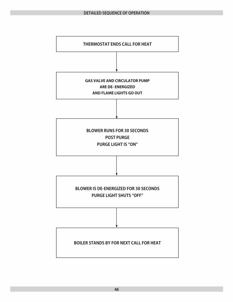
46
deTailed sequenCe of operaTion
THERMOSTAT ENDS CALL FOR HEAT
GAS VALVE AND CIRCULATOR PUMP
ARE DE- ENERGIZED
AND FLAME LIGHTS GO OUT
BLOWER RUNS FOR 30 SECONDS POST PURGE
PURGE LIGHT IS “ON”
BLOWER IS DE-ENERGIZED FOR 30 SECONDSPURGE LIGHT SHUTS “OFF”
BOILER STANDS BY FOR NEXT CALL FOR HEAT
47
importantI1. n a reset from lockout condition, all electrical meter readings at the gas control valve (24 vac) must be taken within the trial for ignition period.If any component does not function properly, make sure it is 2. correctly installed and wired before replacing it.Static electricity discharge can damage the integrated boiler 3. control (IBC). Touch metal surface to discharge static electricity before touching IBC.The IBC cannot be repaired. If it malfunctions it must be 4. replaced.Only trained, experienced service technicians should service the 5. IBC systems. Following troubleshooting, check out the system following the sequence of operation section of this chapter for a normal light off sequence.All controls are factory tested in the assembly process and 6. a defective control is generally the least likely cause. If you suspect you have a defective control, read through the troubleshooting chart before you replace it. It is extremely unlikely that the two consecutive controls are 7. defective. If it seems to be happening, chances are that either there is nothing wrong with the contorl or it is being damaged by some other problem (an electrical short burning out a transformer, for example).
initial service ChecksBefore troubleshooting:1.
Make sure that circuit breaker is on or fuse is ok at A. electrical panel.Make sure that service switch is on.B. Make sure that gas is on at the gas meter, at all appropriate C. manual shutoff valves and at the gas control valve.Make sure that the thermostat is calling for heat.D. Check that wire connectors at the integrated boiler control E. and at the originating control are securely plugged in or connected.Check that hoses are securely connected and are not F. plugged in or damaged.
TroublesHooTing
!
WARNING
Fire, explosion or shock hazard may cause property damage, severe injury or death. Do not attempt to modify the physical or electrical characteristics of this boiler in any way.
Troubleshooting tools:2. Voltmeter to check 120 vac and 24 vacA. Continuity tester.B. Inclined manometer or pressure gauge with 0-2.0” Range C. (0.01” Scale) for measuring suction pressures at pressure switch.U-tube manometer or differential pressure gauge with D. 0-14” range (0.1” Scale) for measuring inlet and manifold gas pressures.
What is system status?3. Consult the chart on the following page.A. Figure #16B. shows the location on the boiler of the diagnostic indicator lamps.
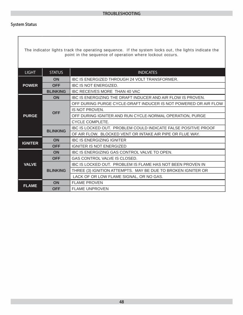
48
The indicator lights track the operating sequence. If the system locks out, the lights indicate the point in the sequence of operation where lockout occurs.
LIGHT STATUS INDICATES
POwERON IBC IS ENERGIzED THROUGH 24 VOLT TRANSFORMER.OFF IBC IS NOT ENERGIzED.
BLINKING IBC RECEIVES MORE THAN 40 VAC
PURGE
ON IBC IS ENERGIzING THE DRAFT INDUCER AND AIR FLOW IS PROVEN.
OFF
OFF DURING PURGE CYCLE-DRAFT INDUCER IS NOT POWERED OR AIR FLOWIS NOT PROVEN.OFF DURING IGNITER AND RUN CYCLE-NORMAL OPERATION, PURGECYCLE COMPLETE.
BLINKINGIBC IS LOCkED OUT. PROBLEM COULD INDICATE FALSE POSITIVE PROOFOF AIR FLOW. BLOCkED VENT OR INTAkE AIR PIPE OR FLUE WAY.
IGNITERON IBC IS ENERGIzING IGNITEROFF IGNITER IS NOT ENERGIzED
VALVE
ON IBC IS ENERGIzING GAS CONTROL VALVE TO OPEN.OFF GAS CONTROL VALVE IS CLOSED.
BLINKINGIBC IS LOCkED OUT. PROBLEM IS FLAME HAS NOT BEEN PROVEN INTHREE (3) IGNITION ATTEMPTS. MAY BE DUE TO BROkEN IGNITER OR LACk OF OR LOW FLAME SIGNAL, OR NO GAS.
FLAMEON FLAME PROVENOFF FLAME UNPROVEN
system status
TroublesHooTing
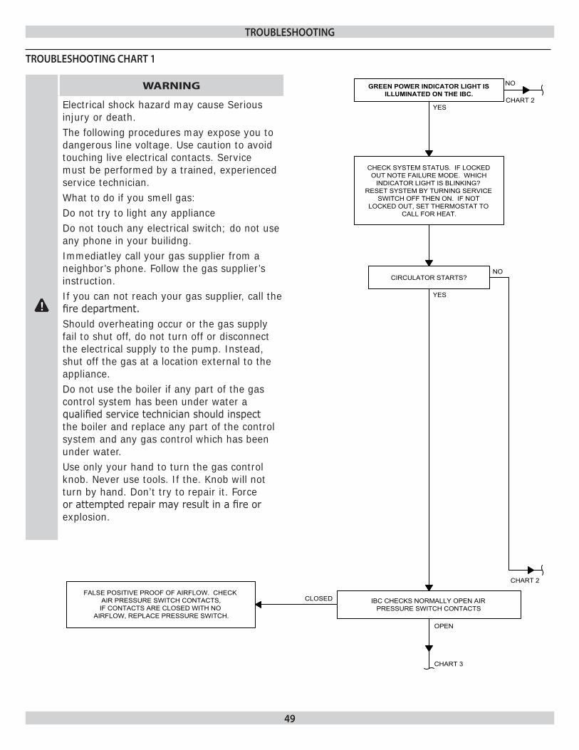
49
TroublesHooTing CHarT 1
TroublesHooTing
!
WARNING
electrical shock hazard may cause Serious injury or death.The following procedures may expose you to dangerous line voltage. use caution to avoid touching live electrical contacts. Service must be performed by a trained, experienced service technician.What to do if you smell gas:Do not try to light any applianceDo not touch any electrical switch; do not use any phone in your builidng.Immediatley call your gas supplier from a neighbor’s phone. Follow the gas supplier’s instruction.If you can not reach your gas supplier, call the fire department.Should overheating occur or the gas supply fail to shut off, do not turn off or disconnect the electrical supply to the pump. Instead, shut off the gas at a location external to the appliance.Do not use the boiler if any part of the gas control system has been under water a qualified service technician should inspect the boiler and replace any part of the control system and any gas control which has been under water.use only your hand to turn the gas control knob. Never use tools. If the. knob will not turn by hand. Don’t try to repair it. Force or attempted repair may result in a fire or explosion.
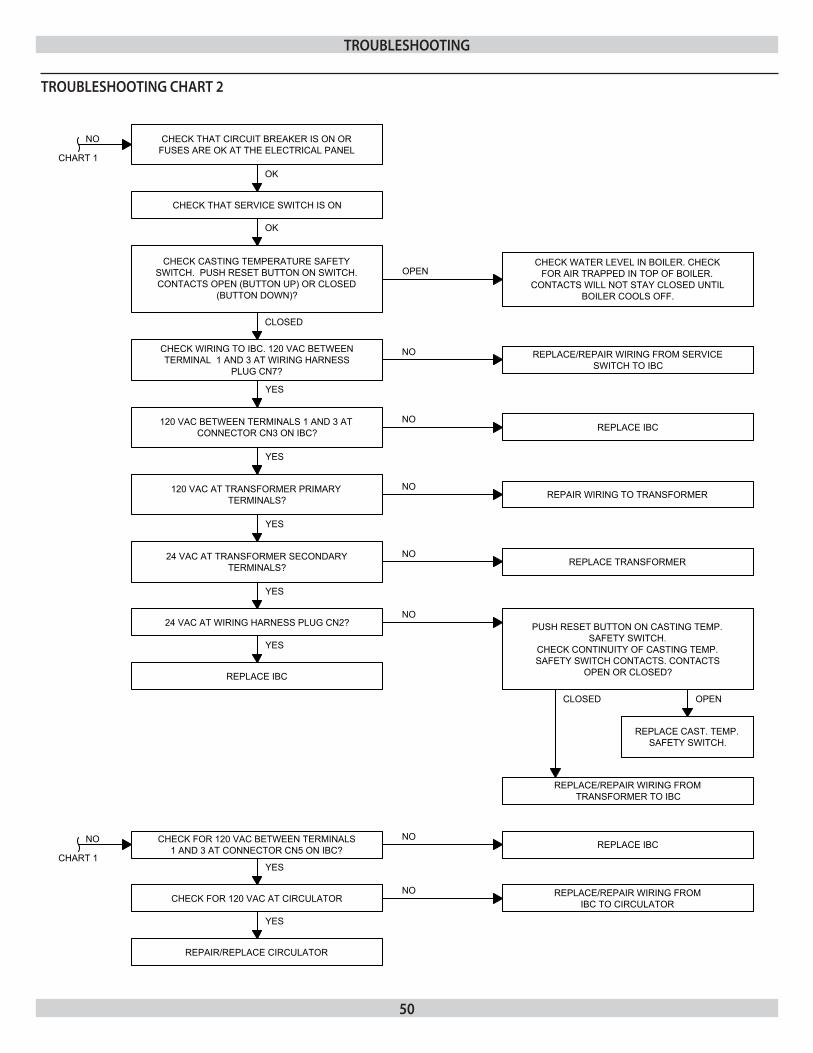
50
TroublesHooTing CHarT 2
TroublesHooTing
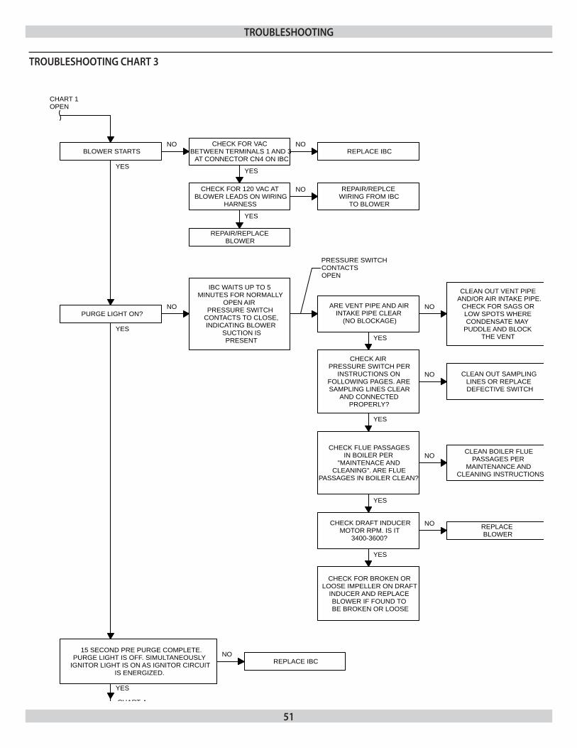
51
CHECK FOR VAC BETWEEN TERMINALS 1 AND 3
AT CONNECTOR CN4 ON IBC
NO NOBLOWER STARTS REPLACE IBC
CHART 1OPEN
PURGE LIGHT ON?NO
YES
IBC WAITS UP TO 5 MINUTES FOR NORMALLY
OPEN AIR PRESSURE SWITCH
CONTACTS TO CLOSE,INDICATING BLOWER
SUCTION IS PRESENT
YES
CHECK FOR 120 VAC AT BLOWER LEADS ON WIRING
HARNESS
YES
REPAIR/REPLACE BLOWER
NO REPAIR/REPLCE WIRING FROM IBC
TO BLOWER
PRESSURE SWITCH CONTACTS OPEN
ARE VENT PIPE AND AIR INTAKE PIPE CLEAR
(NO BLOCKAGE)
NO
CLEAN OUT VENT PIPE AND/OR AIR INTAKE PIPE.
CHECK FOR SAGS OR LOW SPOTS WHERE CONDENSATE MAY
PUDDLE AND BLOCK THE VENTYES
CHECK AIR PRESSURE SWITCH PER
INSTRUCTIONS ON FOLLOWING PAGES. ARE SAMPLING LINES CLEAR
AND CONNECTED PROPERLY?
NO CLEAN OUT SAMPLING LINES OR REPLACE DEFECTIVE SWITCH
YES
CHECK FLUE PASSAGES IN BOILER PER
"MAINTENACE AND CLEANING". ARE FLUE
PASSAGES IN BOILER CLEAN?
NO CLEAN BOILER FLUE PASSAGES PER
MAINTENANCE AND CLEANING INSTRUCTIONS
YES
CHECK DRAFT INDUCERMOTOR RPM. IS IT
3400-3600?
NO REPLACE BLOWER
YES
CHECK FOR BROKEN OR LOOSE IMPELLER ON DRAFT
INDUCER AND REPLACE BLOWER IF FOUND TO BE BROKEN OR LOOSE
YES
15 SECOND PRE PURGE COMPLETE.PURGE LIGHT IS OFF. SIMULTANEOUSLY
IGNITOR LIGHT IS ON AS IGNITOR CIRCUIT IS ENERGIZED.
YES
CHART 4
NOREPLACE IBC
TroublesHooTing CHarT 3
TroublesHooTing
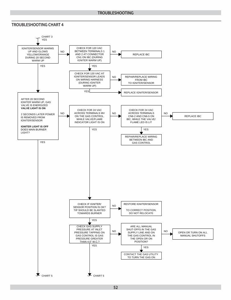
52
IGNITER/SENSOR WARMSUP AND GLOWS
YELLOW/ORANGEDURING 20 SECOND
WARM UP
CHART 3YES
NOCHECK FOR 120 VAC
BETWEEN TERMINALS 1 AND 2 AT CONNECTOR CN1 ON IBC (DURING IGNITER WARM UP)
NOREPLACE IBC
YES
CHECK FOR 120 VAC AT IGNITER/SENSOR LEADS
ON WIRING HARNESS (DURING IGNITER
WARM UP)
NO REPAIR/REPLACE WIRING FROM IBC
TO IGNITER/SENSOR
YES REPLACE IGNITER/SENSOR
AFTER 20 SECOND IGNITER WARM UP, GAS VALVE IS ENERGIZED VALVE LIGHT IS ON
2 SECONDS LATER POWER IS REMOVED FROM IGNITER/SENSOR
IGNITER LIGHT IS OFFDOES MAIN BURNER LIGHT?
CHECK FOR 24 VAC ACROSS TERMINALS MV ON THE GAS CONTROL.
WHILE VALVE/FLAME INDICATOR LIGHT IS ON
NO NOCHECK FOR 24 VAC ACROSS TERMINALS CN6-2 AND CN6-5 ON
IBC, WHILE THE VALVE/FLAME LED IS LIT
NOREPLACE IBC
YES
REPAIR/REPLACE WIRING BETWEEN IBC AND
GAS CONTROL
YES
CHECK IF IGNITER/SENSOR POSITION IS OK?TIP SHOULD BE SLANTED
TOWARDS BURNER
RESTORE IGNITER/SENSOR
TO CORRECT POSITION.DO NOT RELOCATE
NO
YES
CHECK GAS SUPPLY PRESSURE AT INLET
PRESSURE TAPPING ON GAS CONTROL IS GAS PRESSURE GREATER
THAN 4.0" W.C.?
NO
ARE ALL MANUAL SHUT-OFFS IN THE GAS SUPPLY LINE AND ON THE GAS CONTROL IN
THE OPEN OR ON POSITION?
OPEN OR TURN ON ALL MANUAL SHUTOFFS
NO
YES
CONTACT THE GAS UTILITY TO TURN THE GAS ON
YES
CHART 5 CHART 5
YES
YES
TroublesHooTing CHarT 4
TroublesHooTing
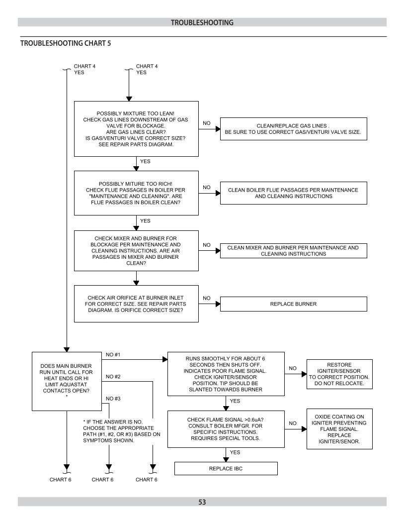
53
TroublesHooTing CHarT 5
TroublesHooTing
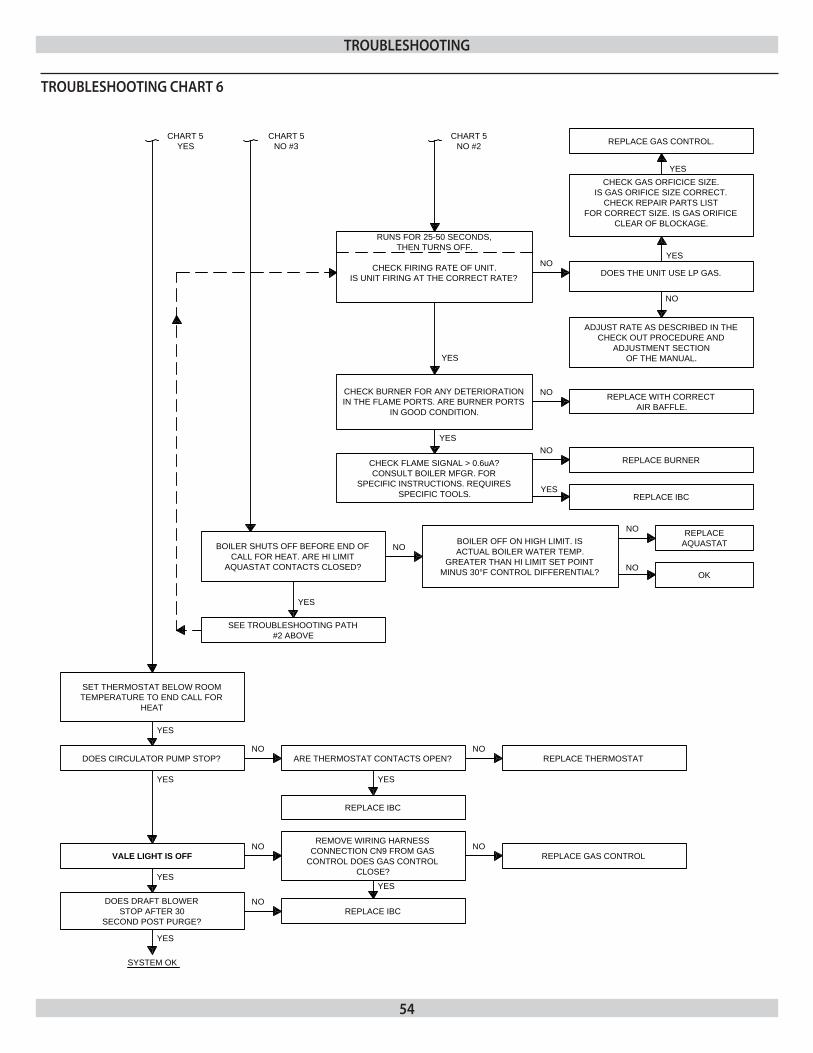
54
RUNS FOR 25-50 SECONDS, THEN TURNS OFF.
CHECK FIRING RATE OF UNIT.IS UNIT FIRING AT THE CORRECT RATE?
NODOES THE UNIT USE LP GAS.
YES
NO
CHECK GAS ORFICICE SIZE.IS GAS ORIFICE SIZE CORRECT.
CHECK REPAIR PARTS LIST FOR CORRECT SIZE. IS GAS ORIFICE
CLEAR OF BLOCKAGE.
ADJUST RATE AS DESCRIBED IN THE CHECK OUT PROCEDURE AND
ADJUSTMENT SECTIONOF THE MANUAL.
CHART 5NO #2
YES
CHECK BURNER FOR ANY DETERIORATION IN THE FLAME PORTS. ARE BURNER PORTS
IN GOOD CONDITION.
NO REPLACE WITH CORRECT AIR BAFFLE.
YES
CHECK FLAME SIGNAL > 0.6uA?CONSULT BOILER MFGR. FOR
SPECIFIC INSTRUCTIONS. REQUIRES SPECIFIC TOOLS.
NO
YES
REPLACE BURNER
REPLACE IBC
BOILER SHUTS OFF BEFORE END OF CALL FOR HEAT. ARE HI LIMIT
AQUASTAT CONTACTS CLOSED?
NOBOILER OFF ON HIGH LIMIT. IS ACTUAL BOILER WATER TEMP.
GREATER THAN HI LIMIT SET POINT MINUS 30°F CONTROL DIFFERENTIAL?
NO
NO
REPLACEAQUASTAT
OK
YES
SEE TROUBLESHOOTING PATH #2 ABOVE
CHART 5NO #3
CHART 5YES
SET THERMOSTAT BELOW ROOM TEMPERATURE TO END CALL FOR
HEAT
DOES CIRCULATOR PUMP STOP?NO
ARE THERMOSTAT CONTACTS OPEN? REPLACE THERMOSTATNO
YES
REPLACE IBC
YES
VALE LIGHT IS OFF
REMOVE WIRING HARNESS CONNECTION CN9 FROM GAS
CONTROL DOES GAS CONTROL CLOSE?
NOREPLACE GAS CONTROL
NO
YES
YES
DOES DRAFT BLOWER STOP AFTER 30
SECOND POST PURGE?
NOREPLACE IBC
YES
YES
SYSTEM OK
YES
REPLACE GAS CONTROL.
TroublesHooTing CHarT 6
TroublesHooTing
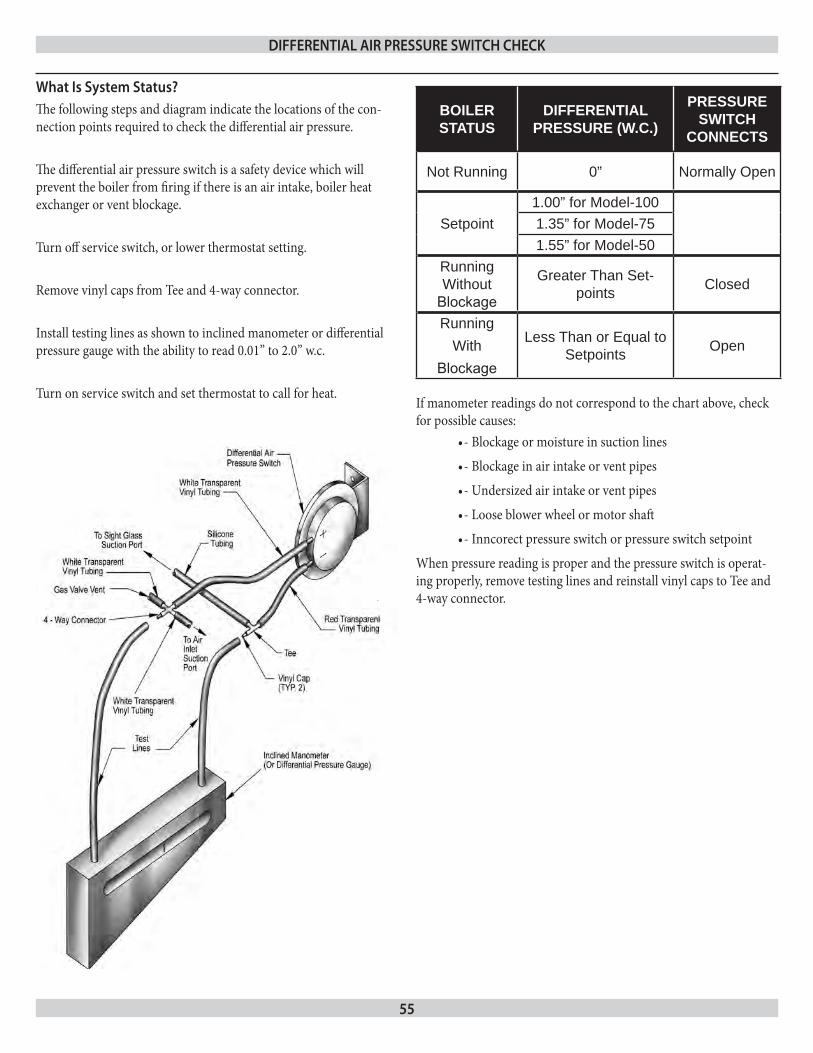
55
The following steps and diagram indicate the locations of the con-nection points required to check the differential air pressure.
The differential air pressure switch is a safety device which will prevent the boiler from firing if there is an air intake, boiler heat exchanger or vent blockage.
Turn off service switch, or lower thermostat setting.
Remove vinyl caps from Tee and 4-way connector.
Install testing lines as shown to inclined manometer or differential pressure gauge with the ability to read 0.01” to 2.0” w.c.
Turn on service switch and set thermostat to call for heat.
BOILER STATUS
DIFFERENTIAL PRESSURE (w.C.)
PRESSURE SwITCH
CONNECTS
Not Running 0” Normally Open
Setpoint1.00” for Model-1001.35” for Model-751.55” for Model-50
Running Without
Blockage
Greater Than Set-points Closed
Running With
Blockage
Less Than or Equal to Setpoints Open
If manometer readings do not correspond to the chart above, check for possible causes:
- Blockage or moisture in suction lines•
- Blockage in air intake or vent pipes•
- Undersized air intake or vent pipes•
- Loose blower wheel or motor shaft•
- Inncorect pressure switch or pressure switch setpoint•
When pressure reading is proper and the pressure switch is operat-ing properly, remove testing lines and reinstall vinyl caps to Tee and 4-way connector.
What is system status?
differenTial air pressure sWiTCH CHeCk

85 Middle Rd.Dunkirk, NY 14048