Embed Size (px)
Citation preview
Operation and Maintenance Manual 3681036666
GARAGE
TABLE OF CONTENTS
Warranty Information ................... 2
Safety Information ..................... 3
Safety Features ......................... 3
Important Installation Instructions ....... 3
Pre-lnstallation Checklist .............. 4-6
Adjustments .......................... 7-8
Programming the Remote Control ...... 8
Installing lightbulb and lens ............. 9
Scheduled Maintenance ............... 10
Troubleshooting Guide ............. 10-11
Wiring Diagram ........................ 12
Parts Lists and Exploded Views ..... 12 -13
Accessories ............................ 14
COMPLETE WiTH INTELLICODE ®REMOTE CONTROL AND SERIESIIELECTRONICS
For 7' 6" Doors. Extension Kit is available for 8' Doors
Included Wall Control MUST be installed prior to Operation
of this Garage Door Operator.
Safe-T-Beam ®Safety Reverse System Must be installed andthe Force Controls MUST be Properly Set to close door.
This Equipment meets or exceeds all Federal, State and UL 325Safety Requirements.
Having Difficulty? Need Help?Please call us:1-800-35-GENIE (354-3643)
www.geniecompany.com
Please have Model information ready when calling.
THE GENIE COMPANY LiMiTED WARRANTY
What is covered?
Any defect in material and product workmanship from personal, normalhousehold usein accordance with the Owner's Manual.
For how long?
MODEL 2020LSeries... 10 yearson motor and 2 yearson all other parts.
Who gets the warranty?
This warranty is limited to the consumer who originally purchasedthe product.
Geographic scope:
This warranty applies only to units installed and operated within the countrywhere they were purchased.
Limitations:
IMPLIEDWARRANTIES,INCLUDINGTHOSEOF FITNESSFORA PARTICULARPURPOSEANDMERCHANTABILITY(AN UNWRITTENWARRANTYTHATTHEPRODUCTISFITFORORDINARYUSE),ARELIMITEDTO ONEYEARFROMTHEDATEOF PURCHASE.GENIEWILL NOT PAY FOR:LOSSOF TIME;INCONVENIENCE;LOSSOF USEOF YOURGENIEPRODUCTORPROPERTYDAMAGECAUSEDBYYOURGENIEPRODUCTORITSFAILURETO WORK;ANYSPECIAL,INCIDENTALORCONSEQUENTIALDAMAGES;OR ANYDAMAGESRESULTINGFROMMISUSEORMODIFICATIONOFYOURGENIEPRODUCT.
Some states and provinces do not allow limitations on how long an impliedwarranty lasts or the exclusion of incidental or consequential damages, so theabove limitations or exclusions may not apply to you.
This warranty is the only one we will give on your Genie product, and it setsforth all our responsibilities regarding your Genie product.There are no otherexpress warranties.
State and province rights: This warranty gives you specific legal rights, andyou may also haveother rights which vary from state to state andprovince toprovince.
How to get warranty service:
To obtain warranty service for your Genie product, you must provide proof ofthe date and place of purchase of the product.
1. Do=it-Yourself-Service.
Call the Genie Customer Servicetoll free at 1.800.354.3643to speak inperson to a trained Genie representative for assistance in diagnosing theproblem and arranging to supply you with the required parts for do-it-yourself repairs.Trained service representatives are available Monday-Friday,8:00 a.m.- 9:00 p.m., EasternTime, and on Saturday, 10:00a.m. to 7:00 p.m.,EasternTime (subject to holidays) You may also get the information youneed at www.geniecompany.com.
2.Service From Authorized Dealers.Youalsomayobtainwarrantyservicefrom GenieauthorizeddealersbycallingtheGenieCustomerServiceat 1.800.354.3643or byvisitingwww.geniecompony.combeforeschedulingwarrantyservice.If warrantyserviceisprovidedbyan authorizeddealer,Geniewill provideallrequiredpartsunderwarrantyat no chargeto you,butthe dealersareindependentbusinesspeopleandmayrendera benchor servicecallchargefor their services.Geniewill not reimburseyouorotherwiseberesponsibleforthosecharges.
Wesuggestthat youretainyouroriginalpackingmaterialin theeventwe chooseto repairor replaceyour GenieProductand requestthat youshipit to us.Besuretoincludeyour name,address,telephonenumber,proof of dateand placeof purchaseand adescriptionof the operatingproblem.After repairingorreplacing,yourGenieproduct,we will ship it to yourhomeat no costto youfor partsand labor,but youwillhaveto paya minimumof $S.00forshippingand handlingcharges.
Yourchoiceof eitheroneof the above-describedserviceoptionsisyour exclusiveremedyunderthis warranty.
What this warranty does not cover:
Thiswarrantydoesnotcoverbatteries(whichareconsideredreplaceableparts),installation,commercialuse,defectsresultingfrom accidents,damagewhile intransit
to ourservicelocationordamageresultingfrom alterations,misuseorabuse,lackofpropermaintenance,unauthorizedrepairor modificationof the product,affixingofanyattachmentnot providedwith the product, programmingof the RemoteControlDevices,Safe-T-Beam®adjustment/cleaning,staplesthrough wiring, pinchedor brokenwires,Carriagedisengaged,ForceControladjustments,door out of balance,brokenspringsor cables,poweroutages,useof extensioncords,missingordamagedpartsondiscounted,clearanced,final saleor tapedcartons,phantomoperations(labor isnotcoveredif Openeris functioning properlywhile technicianis in garage),fire,flood,oractsof God,orother failureto follow the Owner'sManual.
Pleasenote the following information,soit is availableif youneed to call us.
Date Purchased / /
Serial Number*
Operator Model*Dealer Name
DealerAddress
City
State / Zip
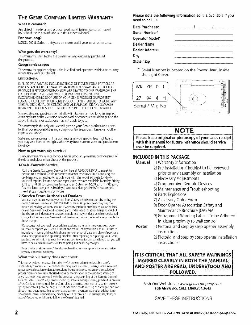
eeSerial Number is located on the Power Head, insidethe Light Cover.
WK YR P I'_
Serial/Mfg No.
NOTEPleasekeep original or photocopy of your sales receiptwith this manual for future reference shouldserviceever be required.
INCLUDED IN THIS PACKAGE
Manual 1)Warranty Information2) Pre Installation Checklist to be reviewed
prior to any assembly or installation3) Necessary Adjustments4) Programming Remote Devices5) Maintenance and Troubleshooting6) Parts Explosions7) Accessory Order Form8) Door Opener Association Safety and
Maintenance Brochure (DASMA)
9) Entrapment Warning Label- To be Adheredin close proximity to wall control
Poster 1) Pictorial and step by step opener assemblyinstructions
2) Pictorial and step by step opener installationinstructions
MARKED CLEARLY IN BOTH THE MANUALlAND POSTER ARE READ, UNDERSTOOD AND
FOLLOWED;
Visit Our Website at: www.geniecompany.comFORANSWERS:CALL1.800.354.3643
SAVE THESE INSTRUCTIONS
2 For Help, call 1=800-3S-GENIE or visit www.geniecompany.com

OVERVIEW OF POTENTIAL HAZARDSOverhead doors are large,heavy objects that move with the help of springs under high tension and electric motors. Sincemoving objects, springsunder tension, and electric motors cancauseinjuries, your safetyand the safety of others depend on you reading the information in this manual. If youhavequestions or do not understand the information presented, callThe Genie Company. or your local GenieDistributor.
In this section, and those that follow, the words Danger, Warning and Caution are used to emphasize important safetyinformation. The word:
DANGER: indicates an imminently hazardous situation which, if not avoided, will result in death or serious injury.
WARNING: indicates a potentially hazardous situation which, if not avoided, could result in death or serious injury.
CAUTION: indicates a potentially hazardous situation which, if not avoided, may result in injury or property damage.
The word NOTE is used to indicate important steps to be followed or important considerations.
POTENTIAL HAZARD
MOVING DOOR
ELECTRICALSHOCK
HIGH SPRINGTENSION
EFFECT PREVENTION
WARNING: . Keep people clear of opening while door is moving.Could result in death oDo Not allow children to play with the door operator.
or serious injury, oDo Not operate a door that jams or one that has a broken spring.
WARNING:Could result in death
or serious injury.
WARNING:Could result in death
or serious injury.
oTurn off power before removing operator cover.
oWhen replacing cover, make sure wires are not pinched or nearmoving parts.
oOperator must be properly grounded.
. Do Not try to remove, repair or adjust springs or anything towhich door spring parts are fastened, such as, wood blocks,steel brackets, cables or other like items.
o Repairs and adjustments must be made by a trained doorsystem technician using proper tools and instructions.
MPORTANT INSTALLATIONNSTRUCTIONS
WARN ING:TO REDUCE THI RISK
OF SEVERE INJURY OR DEATH:1 READAND FOLLOWALL SAFETY,INSTALLATIONAND OPERATION
INSTRUCTIONS.If you have any questions or do not understandan instruction, call your authorized Genie installation professional.
2 Do Not install operator on an improperly balanced door. Animproperly balanced door could cause severe injury. Repairs andadjustments to cables, spring assembly, and other hardwaremust be made by a trained service person using proper toolsand instructions.
3 Remove all ropes, and disable all locks connected to the doorbefore installing operator.
4 Install door operator 7 feet or more above the floor. Mount theemergency release knob 6 feet above the floor.
5 Do Not connect the operator to the source of power untilinstructed to do so.
6 Locatethe control button:
• Within s!ght of door.• At a minimum height of Sfeet, so small children cannot reach it.• Awayfrom all moving parts of the door.
7 Install the entrapment WARNING label next to the wall button orconsole. Install the emergency release tag on, or next to, theemergency release.
8 The operator must reverse when the door contacts a 1-1/2 inch
high object on the floor at the center of the doorway. This isabout the size ofa 2 x 4 board aid fat.
SAFETY FEATURES
Safe-T-Beam® (STB) Non-Contact
Reversing SystemPlacesan invisiblebeam across door opening, thatreverses the door during down travel to the fullyopen position if anything passesthrough beam.
Safe-T-Reverse® Contact Reversing SystemAutomatically stops and reverses a closing doorwithin 2 seconds of contact with an object.
Safe-T-Stop® Timed Reversed SystemAutomatically opens a closing door, if door does notclose within 30 seconds.
ForceGuard Control
Used to set the force required for opening and clos-ing door. For maximum safety, set the minimumforce required to fully open and close door.
Automatic Lighting SystemLight bulbs up to 60 Watts max., used for saferentries and exits. The lights turn on when doorisactivated and automatically turn off 4.5minutes later.
Manual Emergency ReleaseAllows the garage door to be opened or closedmanually for emergencies or maintenance.
For Help, {all 1-800-35-GENIE or visit www.geniecompany.com :3
PRE=INSTALLATION CHECKLISTThis Opener includes parts and supplies needed to install in mostgarages and connect to most garage doors. There are many variationsof garagesand garage doors. A few additional parts and supplies maybe needed to install Opener into your garage and connect to yourgarage door. While checking items listed below, note any additionalitems you will need.Tools used in this section:
• 12% Tape Measure • Pencil • Ladder • Level
Check following items before assembling Opener:
Check condition of vertical stile in center of door, and its connection to
door's top and bottom beams. (Figure 1)
A If door frame is nailed together and not a solid connection, doorframe must be braced or reinforced before installing Opener.
B If door is "lightweight" (made with frame and skin - not solid),door (including door frame) must be braced or reinforced beforeinstalling Opener.
C A door opener reinforcement bracket may also be needed toconnect garage door to Opener's Door Bracket. This Opener isdesigned for installation on a properly braced sectional door orsolidly braced one-piece door.
D Contact your Genie Factory Authorized Dealer or dealer of yourgarage door for any necessarybracing and a door openerreinforcement bracket (if needed) before proceeding.
E If you have a wooden door, measuredoor's thickness. If your dooris lessthan 2" thick, brace door or useshorter Door Bracket LagScrews(1/4" x 1-1/4"- not included)
AND BALANCE
A Raisedoor, check alignment and see if it moves freely (Figure 2).If door appears out of alignment, binds, or does not move smoothly,contact a Genie Factory Authorized Dealer or dealer of your garagedoor for repairs and adjustments to door mechanism.
B Raisedoor to 3' - 4' above ground and carefully let go. Doorshould stay stationary. Slight movement is acceptable. More thanslight movement meansdoor is out of balance. Contact a GenieFactory Authorized Dealer or dealer of your garagedoor for repairs and adjustments to door mechanism.
....::::-:::::: KEEP FEET CLEAR OF DOOR
One-PieceDoor
Figure 2 Checking door balance
WARNING:Ifyour door sticks, binds, or is out of balance, have it adjustedby a Genie Factory Authorized Dealer. Door springs, cables,pulleys, brackets and associatedhardware are under extremetension and can cause serious injury or death.
4
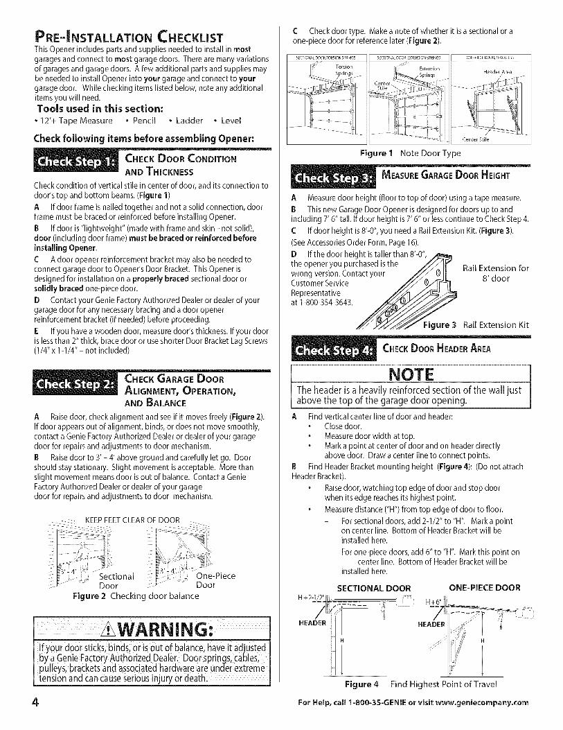
C Check door type. Makeanoteofwhetheritisasectionaloraone-piece door for reference later (Figure 2).
SECTIONAL DOOR,TORSION SPRINGS SECTIONAL DOOR, EXTENSION SPRINGS ONEPIECEDOOR,TRACKLESS
Header Area
Center Stile
Figure 1 Note Door Type
A Measuredoor height (floor to top of door) using a tape measure.
B This new Garage Door Opener is designed for doors up to andincluding 7' 6" tall. If door height is7' 6" or lesscontinue to Check Step 4.
C If door height is 8'-0", you need a Rail Extension Kit. (Figure 3).
(SeeAccessoriesOrder Form,Page 16).
D If the door height is taller than 8'-0",
the opener you purchased is the Rail Extension forwrong version. Contact 8' doorCustomer Service
Representativeat 1-800-354-3643.
Figure 3 Rail Extension Kit
NOTEThe header is a heavily reinforced section of the wall justabove the top of the garage door opening.
A Find vertical center line of door and header:• Close door.
• Measuredoor width at top.• Mark a point at center of door and on headerdirectly
above door. Draw a center line to connect points.
B Find Header Bracketmounting height (Figure 4): (Do not attachHeader Bracket).
• Raisedoor, watching top edge of door and stop doorwhen its edge reachesits highest point.
• Measuredistance ("H") from top edge of door to floor.
- Forsectional doors, add 2-1/2" to "H". Mark a pointon center line. Bottom of Header Bracket will beinstalled here.
- Forone-piece doors, add 6" to "H". Mark this point oncenter line. Bottom of Header Bracketwill be
installed here.
SECTIONAL DOOR
H÷2_J=2_......
H
ONE-PIECE DOOR
Figure 4 Find Highest Point of Travel
ForHelp,call 1-800-3S-GENIEorvisit www.geniecompany.com
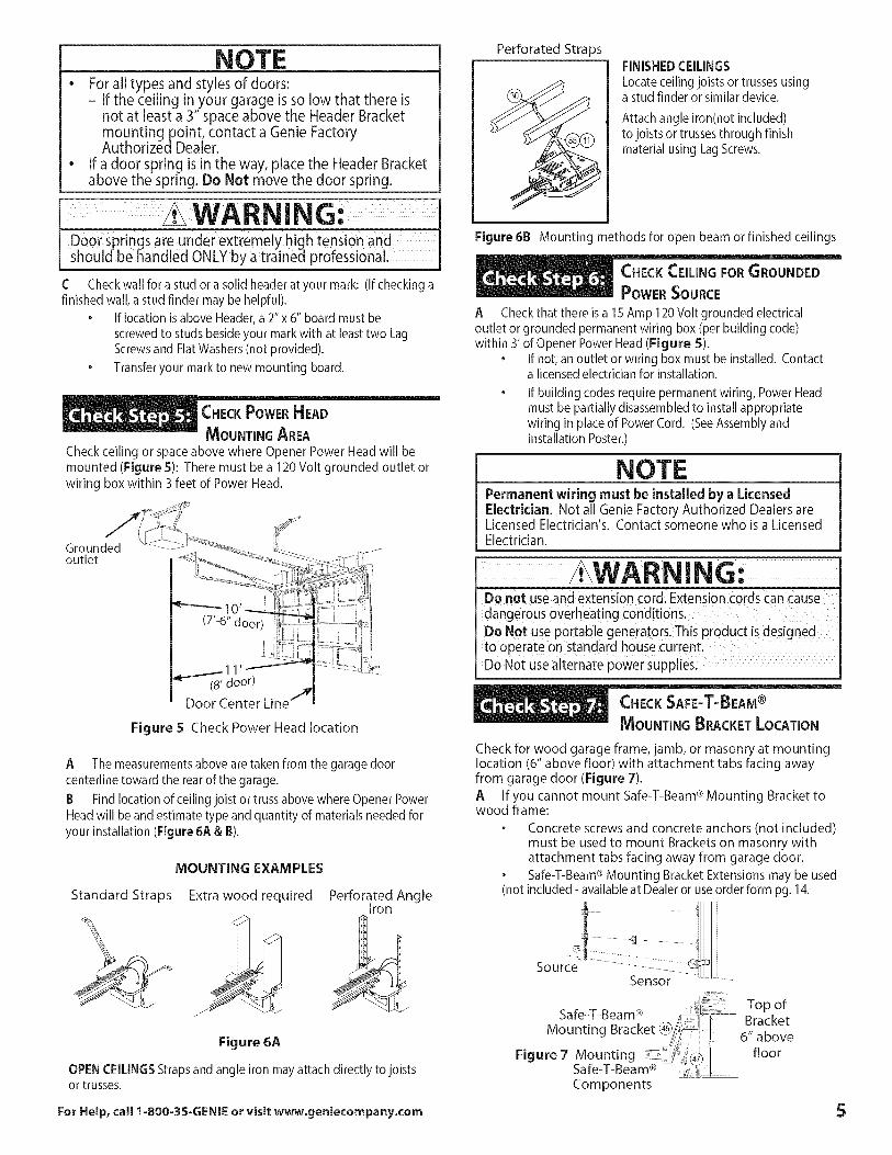
NOTE• For all types and styles of doors:
- If the ceiling in your garage is so low that there isnot at least a 3" space above the Header Bracketmountingpoint, contact a Genie FactoryAuthorizedDealer.
• If a door spring is in the way, place the Header Bracketabove the spring. Do Not move the door spring.
WARNING:Door springs are under extremely high tension andshou d be hand ed ONLYby a trained professiona.
C Check wall for a stud or a solid headerat your mark: (If checking afinished wall, a stud finder may be helpful).
• If location is above Header,a 2"x 6" board must be
screwed to studs beside your mark with at least two LagScrewsand Flat Washers(not provided).
• Transfer your markto new mounting board.
Check ceiling or space above where Opener Power Head will bemounted (Figure 5): There must be a 120Volt grounded outlet orwiring box within 3 feet of Power Head.
Groundedoutlet
1(8' door)
Door Center Line
Figure S Check Power Head location
A The measurements above are taken from the garage doorcenterline toward the rear of the garage.
B Find location of ceiling joist or truss above where Opener PowerHead will beand estimate type and quantity of materials needed foryour installation (Figure 6A & B).
MOUNTING EXAMPLES
Standard Straps Extra wood required Perforated AngleIron
Figure 6A
OPENCEILINGSStrapsand angle iron may attach directly to joistsor trusses.
For Help, call 1=800=35=GENIEor visit www.geniecompany.com
Perforated StrapsFINISHEDCEILINGSLocateceilingjoistsor trussesusingastudfinderorsimilardevice.
Attach angle iron(not included)to joists or trusses through finishmaterial using LagScrews.
Figure 6B Mounting methods for open beam or finished ceilings
POWERSOURCE
A Check that there is a 15Amp 120 Volt grounded electricaloutlet or grounded permanent wiring box (per building code)within 3' of Opener Power Head(Figure S).
• If not, an outlet or wiring box must be installed. Contacta licensed electrician for installation.
If building codes require permanent wiring, Power Headmust be partially disassembled to install appropriatewiring in place of Power Cord. (SeeAssembly andInstallation Poster.)
NOTEPermanent wiring must be installed by a LicensedElectrician. Not all Genie Factory Authorized Dealers areLicensed Electrician's. Contact someone who is a LicensedElectrician.
WARNING:Do not use and extension cordi Extension cords Can cause
dangerous overheating COnditions:
Do NOt Use p0rtable generat0rs: This pr0duct is designedto operate on standard house current;
DoNot use alternate power supplies.
MOU_ lJ.......... n ......., ......NNTINGBRACKET LOCATIO
Check for wood garage frame, jamb, or masonry at mountinglocation (6" above floor) with attachment tabs facing awayfrom garage door (Figure 7).
A If you cannot mount Safe-T-Beam ®Mounting Bracket towood frame:
. Concrete screws and concrete anchors (not included)must be used to mount Brackets on masonry withattachment tabs facing away from garage door.
Safe-T-Beam®Mounting Bracket Extensions may be used(not included - available at Dealer or useorder form pg. 14.
I
_i_ / ...........: TopofSafe-T-Beam ® Bracket
Mounting Bracket@/_ / 6"_i _rr above
Figure 7 Mounting I floorSafe-T-Bea _ ......Components
5
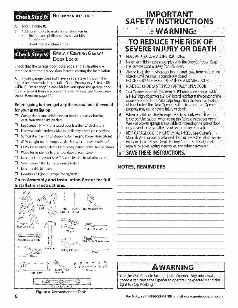
A Tools(FigureS):
B Additional tools to make installation easier:
• Slotted and phillips screw-driver bits• Stud finder
• Sheet-metal cutting snips
Check that the garage door locks, rope, and T-Handles are
removed from the garage door before starting the installation.
A If your garage does not have a separate entry door, it ishighly recommended to install a Genie Emergency Release Kit
(GER-2). Emergency Release Kit lets you open the garage doorfrom outside if there is a power failure. (Please see Accessories
Order Form on page 14.)
Before going further, get any items and tools if needed
for your installationGarage door frame reinforcement brackets, screws, bracingor reinforcement kits (dealer)
Lag Screws(1-1/4") for a wood door lessthan 2" thick (store)
Electrical outlet and/or wiring (supplied by a licensed electrician)
Sufficient angle iron or strapping for hanging Power Head(store)
60 Watt light bulbs (Rough service bulbs recommended)(store)
GER-2Emergency ReleaseKit for entry during power failure (store)
Wood for header, ceiling, and/or door braces(store)®Masonry fasteners for Safe-T-Beam Bracket installation (store)
Safe-T-Beam®Bracket Extensions(dealer)
Masonry drill bit (store)
Extension Kit (for 8' Garage Doors)(dealer)
Go to Assembly and Installation Poster for fullInstallation Instructions.
Adjustable Wrench
Hammer
1t16" 5/32" Tape Measure'_Drill Bit Drill Bit
WireStripper
Safety Glasses
Phillips Screwdriver
Flat Blade Screwdriver
CF i_ ::: :: ....................
Pencil
Hack Saw Wrench
1/4" 5/I6" 3/8" 7/16" 1/2" 9/16"Sockets
6
Carpenter's Level
Figure 8 Recommended Tools
IMPORTANTSAFETY INSTRUCTIONS
!LWARNING:TO REDUCE THE RISK OF
SEVERE iNJURY OR DEATH1 READANDFOLLOWALLINSTRUCTIONS.
2 Neverlet childrenoperateor playwith the DoorControls.Keepthe RemoteControlawayfrom Children.
3 Alwayskeepthe movingdoor insightand awayfrom peopleandobjectsuntil the door iscompletelyclosed.NOONESHOULDCROSSTHEPATHOFA MOVINGDOOR.
4 NEVERGOUNDERA STOPPED,PARTIALLYOPENDOOR.
5 TestOpenermonthly. The,door MUSTreverseon contactwitha 1-1/2 highobject (ora 2 x4 board laid flat)atthe centerofthedoorwayonthe floor. Afteradjustingeitherthe Forceor the Limitof travel,retestthe DoorOpener Failureto adjustthe Openerproperly maycausesevereinjury ordeath.
6 Whenpossibleusethe EmergencyReleaseony when the doorisclosed. Usecautionwhen usingthis Releasewith dooropen.Weakor brokenspringsarecapableof increasingthe rateof doorclosureand increasingthe riskof severeinjury ordeath,
7 KEEPGARAGEDOORSPROPERLYBALANCED.SeeOwner'sManual.An improperlybalanceddoor increasesthe riskof severeinjury ordeath. HaveaGenieFactoryAuthorizedDealermakerepairsto cables,springassemblies,andother hardware,
8 SAVETHESEINSTRUCTIONS.
NOTES, REMINDERS
AWARNINGuse the Wall Console induded_ith opener:Any, other wallconsole can causethe Opener to operat e unexPectedly and thelight to stop working. 1
For Help, call 1-800-35-GENIE or visit www.geniecompany.com
_DJUSTMENTS
SET LIMIT SWITCHES AND
FORCECONTROLS
Coarse Setting of Limit Switches
A Setting Close Limit Switch. Check that Carriage Assembly is disengaged.. With garage door fully closed, slide Close Limit Switch
until it is aligned with the center of theCarriage Assembly.
. Tighten Set Screw. Do Not over-tighten.
B Setting Open Limit Switch. Manually open garage door to full open position.. Slide Open Limit Switch until it is aligned with the center
of the Carriage Assembly.. Tighten Set Screw. Do not over-tighten.. Re-engage Carriage Assembly.
Setting Force Controls and Final Adjustment ofLimit Switches
i, The garage door opens rapidlyi and Cancause serious: injury or deathl; Keep the path Clear:' Position the ladde[ to the Side of the Power Head Soit iS
Clear ofall moving parts ofthe Opener and the door,
Set the dooi Opener to use the minimum force neededto open the door.
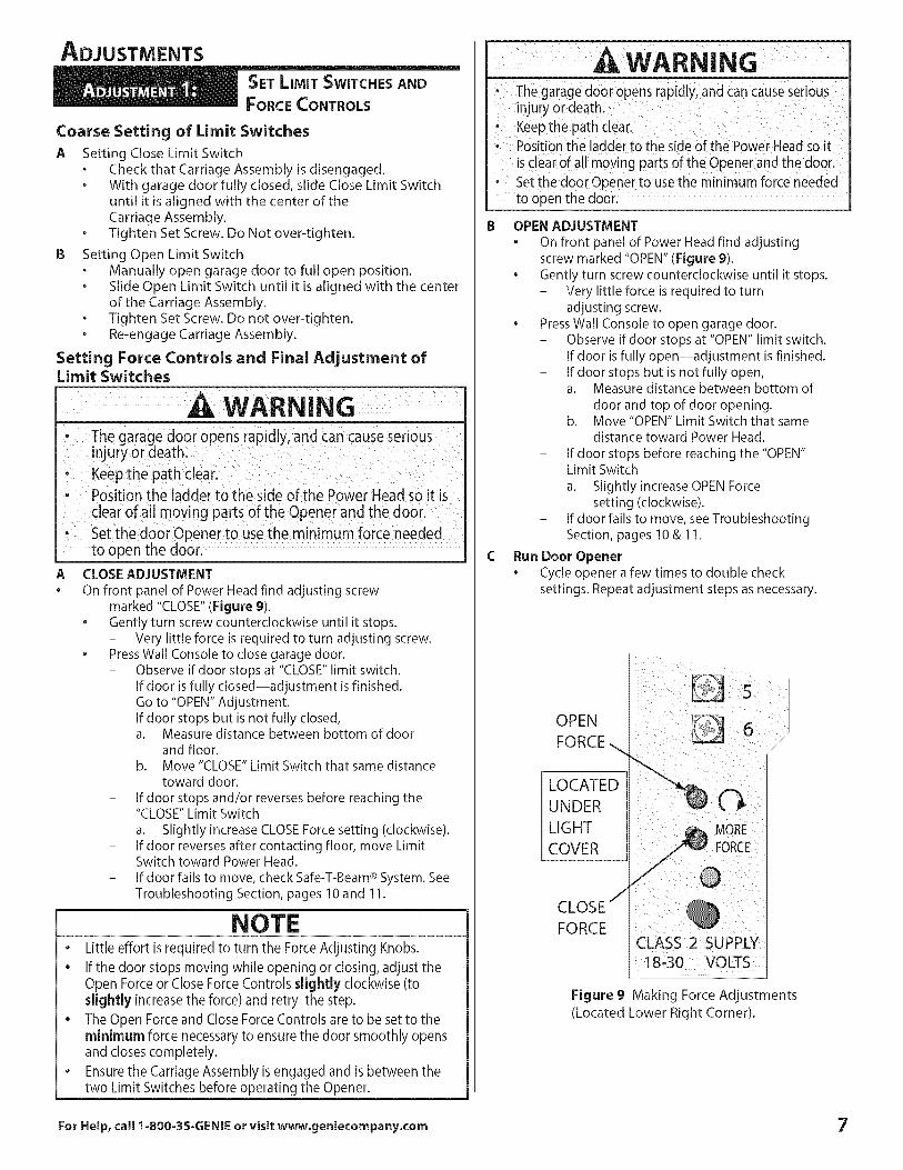
CLOSE ADJUSTMENT
On front panel of Power Head find adjusting screwmarked "CLOSE" (Figure 9).
• Gently turn screw counterclockwise until it stops.- Very little force is required to turn adjusting screw.
• Press Wall Console to close garage door.- Observe if door stops at "CLOSE" limit switch.
If door is fully closed--adjustment is finished.Go to "OPEN" Adjustment.
- If door stops but is not fully closed,a. Measure distance between bottom of door
and floor.b. Move "CLOSE" Limit Switch that same distance
toward door.
- If door stops and/or reverses before reaching the"CLOSE" Limit Switch
a. Slightly increase CLOSEForce setting (clockwise).- If door reverses after contacting floor, move Limit
Switch toward Power Head.
- If door fails to move, check Safe-T-Beam ®System. SeeTroubleshooting Section, pages 10 and 11.
Ao
NOTE• Little effort isrequiredto turn the ForceAdjusting Knobs.• If the door stops moving while opening or closing, adjust the
Open Forceor CloseForceControls slightly clockwise (toslightly increasethe force) and retry the step.
• The Open Forceand CloseForceControls are to be set to theminimum force necessaryto ensure the door smoothly opensand closescompletely.
• Ensurethe CarriageAssembly is engaged and is between thetwo Limit Switches before operating the Opener.
The garaged0oi Opensrapidly;and can causeSeiOusinjury Ordeath:Keepthe path clear:Positionthe ladder to the side Ofthe Power Head so it
is € earof al! mo_ing parts of the Opener and the doori; Set the door opener to usethe minimum force needed
to open the door:
IB OPEN ADJUSTMENT
• On front panel of Power Head find adjustingscrew marked "OPEN" (Figure 9).
• Gently turn screw counterclockwise until it stops.- Very little force is required to turn
adjusting screw.• Press Wall Console to open garage door.
- Observe if door stops at "OPEN" limit switch.If door is fully open--adjustment is finished.
- If door stops but is not fully open,a. Measure distance between bottom of
door and top of door opening.b. Move"OPEN" Limit Switch that same
distance toward Power Head.
- If door stops before reaching the "OPEN"Limit Switch
a. Slightly increase OPEN Forcesetting (clockwise).
- If door fails to move, see TroubleshootingSection, pages 10 & 11.
C Run Door Opener• Cycle opener a few times to double check
settings. Repeat adjustment steps as necessary.
OPEN
FORCE ...
LOCATED
UNDER
LIGHT
COVER
CLOSE /
FORCECLASS 2 SUPPLY18-30 VOLTS
Figure 9 Making Force Adjustments
(Located Lower Right Corner).
For Help, call 1-800-35=GENIE or visit www.geniecompany.com 7
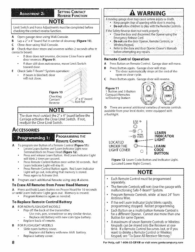
SETTING CONTACT
REVERSEFUNCTION
NOTELimit Switch and ForceAdjustments must be completed beforechecking the contact reversefunction.
A Open garage door using Wall Console.
B Lay a 2" x 4" board flat in center of doorway (Figure 10).
C Close door using Wall Console.
D Check that door stops and reverses within 2 seconds after itcontacts board:
• If door does not reverse, decrease Close Force untildoor reverses (Figure 9).
• If door still does not reverse, move Limit Switchtoward door.
E Check Safe-T-Beam ®System operation:
• If beam is blocked, doorwill not close.
Figure 10 F
Checking _J2" x 4" boardContact
/J_-_ laid flatReverse
NOTEThe door must contact the 2" x 4" board before theCarriage activates the Close Limit Switch. If not,readjust the Close Limit Switch.
ACCESSORIES
PROGRAMMING THE
REMOTE CONTROL
A To program one Button of a Remote Control (Figure 11):• Locate Learn Button and Learn Indicator Light near
Terminal Block on Power Head (Figure 12).• Press and release Learn Button. Red Learn Indicator Light
will blink 2 times per second.• Press Remote Control Button once within 30 seconds. Red
Learn Indicator Light will stay lit.• Press Remote Control Button again. Red Learn Indicator
Light will go out, indicating that memory is stored.• Press again to Activate Unit.
B Program each additional Remote using step A above.
To Erase All Remotes from Power Head MemoryA Press and hold Learn Button on Power Head for 10 seconds
or until Learn Indicator Light goes out. Memory is erased:• Program Remotes again as needed.
To Replace Remote Control BatteryA FOR NON-FLASHLIGHTMODELS
• Pop off the back of the transmitter.
- Use coin, pen, screwdriver or any similar device.- Replace old Battery with new coin type battery.
o Replace back of remote.
B FOR FLASHLIGHT MODELS
• Slide open battery cover.- Replace old Battery with new AAA battery.
o Replace battery cover.
A WARNINGAmoving garagedoor maycauseserious njury or death.
--_ Keeppeopleclearof openingwhile door is moving.Do not allow children to play with the RemoteControls,
If the SafetyReversedoesnot work properly:" Closethe door anddisconnect the Openerusingthe
EmergencyReleaseCord., Donot usethe door Opener,RemoteControls,or
WirelessKeypad.• Referto the door anddoor 0 penerOwner'sManuals
beforeattempting any repairs.
Remote Control OperationA
B
Figure 1 11-Button and 3-ButtonCompact Remotesw/Docking Station
Press Button on Remote Control. Garage door will move.
Press Button again. Garage door will stop:• The door automatically stops at the end of the
open or close cycle.
Press Button again. Garage door will reverse.
D There are several additional varieties of remote controls
available from your local dealer, some equipped witha flashlight.
LOCATEDUNDERTHELIGHT COVER
_b
©....@(hCLOSE@ MOREFORCE
©
LEARNINDICATOR
_-- LIGHT
---- LEARNCODEBUTTON
Figure 12 Learn Code Button and Indicator Light.
(Located Lower Right Corner).
NOTEe Each Remote Control must be programmed
separately.
• The Remote Controls will not close the garage withmalfunctioning Safe-T-Beam® System.
• Program Remote Controls, while at least 24" fromAntenna Wire.
• If the red Learn Indicator Light blinks rapidly,programming stopped. Restart programming.
• Each Button on a multi-button Remote Control isfor a different Opener. Cannot use more than oneButton for same Opener.
• A maximum of seven Remote Controls or Wireless
Keypads can be stored into the Receiver at onetime. If a Remote Control becomes lost, or if youwant to delete a Remote Control or Wireless
Keypad, see "To EraseAll Receiver Memory."
8 For Help, call 1-800-3S-GENIE or visit www.geniecompany.com
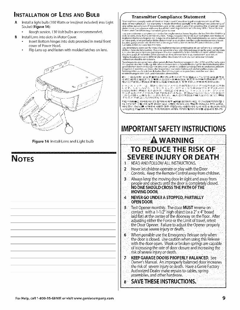
iNSTALLATiON OF LENSAND BULB
A Install a light bulb (1O0Watts or less)(not included) into LightSocket (Figure 14):
• Rough service, 130 Volt bulbs are recommended.
B Install Lens into slots in Motor Cover.
• Insert Bottom hinges into slots provided in metal frontcover of Power Head.
• Flip Lens up and fasten with molded latches on lens.
Figure 14 Install Lens and Light bulb
NOTES
Transmitter Compliance StatementTransmitters comply with all United States and Canadian legal requirements as of the
date of manufacture No warranty is made that they comply with all legal requirements of
any other jurisdiction.If transmitters are to be used in another country, the importer must
determine compliance with any local laws and regulations which may differ from United
States and Canadian requirements prior to use.
Los transmisores cumplen con todas las reglamentaciones [egales de los Estados Unidos y
del Canad&, en [a fecha de fabricaci6n. Ninguna garantfa se da que cumplan con todas as
reglamentaciones legales de ninguna otra jurisdicci6n. Si los transmisores se van a utilizar
en otro pals, el importador debe determinar si cumplen con las reglamentaciones y [eyes
locales que puedan ser diferentes a las reglamentaciones de los Estados Unidos y delCanad& antes de usar los mismos.
Les emetteurs sont conformes _ la reglementation am_ricaine et canadienne _ compter
de leur date de fabrication. Aucune garantie n'est stipul6e indiquant qu'ils sont conformesroutes [es prescriptions juridiques d'autres autorit_s. Si les _metteurs sont utilis_s dans
d'autres pays, i[ incombe a I'importateur d'en d_terminer leur conformit_ aux lois et
regles locales pouvant diff_rer de celes des Etats-Unis et du Canada avant touteutilisation desdits _metteur£
Sendeger_ite entsprechen allen gesetzlichen Bestimmungen in den USA und Kanada zum
Zeitpunkt der Herstellung,Wir Obernehmen keine Gew_ihrleistung for die Einhaltung aller
gesetzlichen Bestimmungen in anderen Lindem. Sollen Sendegerite in anderen L_ndem
eingesetzt werden, so muss der Importeur vor dem Gebrauch sicherstellen, dass die
Sendeger_te auch solchen Iokalen Bestimmungen entsprechen, wekhe yon denBestimmungen der USA und Kanadas abweichen.
nlF+-t iOl 71El Ef-_--_ xlgqlAt +,"-f&_-I _-,'q:>- _-_°_;q_i,q_SFTlO_l o_,,ti _lq_t _HI-F.F_P--IS_
F&_,_I _l-@_Cl_____ :::z _Cl c" I _'_f __allOtl [qe-l-oi: _;q°l o:i _ z_oHof
IMPORTANTSAFETYINSTRUCTIONS
WARNING--TO REDUCE THE RISK OF
SEVERE INJURY OR DEATH1 READAND FOLLOWALLINSTRUCTIONS.
2 Never let children operate or play w th the Doo_Controls. Keepthe Remote Control away from children.
3 Always keep the moving door in sight and away frompeople and objects until the door iscompletely closed.NO ONE SHOULD CROSSTHE PATH OF THEMOVING DOOR.
4 NEVERGO UNDERA STOPPED,PARTIALLYOPEN DOOR.
5 Test Opener monthly,. The door MUST reverse oncontact with a 1-1/2 high object (ora 2 x 4 boardlaid flat) at the center of the doorway on the floor. Afteradjusting either the Forceor the Limit of travel, retestthe Door Opener. Failureto adjust the Opener properlymay causesevere injury or death,
8 When possibleusethe EmergencyReleaseonly whenthe door isc osed. Usecaution when using this Reeasewith the dooropen. Weakor brokenspringsare capableof increasingthe rateof door closureand increasingtheriskof severeinjuryor death.
7 KEEPGARAGEDOORS PROPERLYBALANCED. SeeOwner's Manual. An improperly balanced door increasesthe risk of severe injuryor death. Havea Genie FactoryAuthorized Dealer make repairs to cables,springassemblies,and other hardware.
8 SAVETHESEINSTRUCTIONS.
For Help, call 1-800-3S-GENIE or visit www.genie¢ompany.com
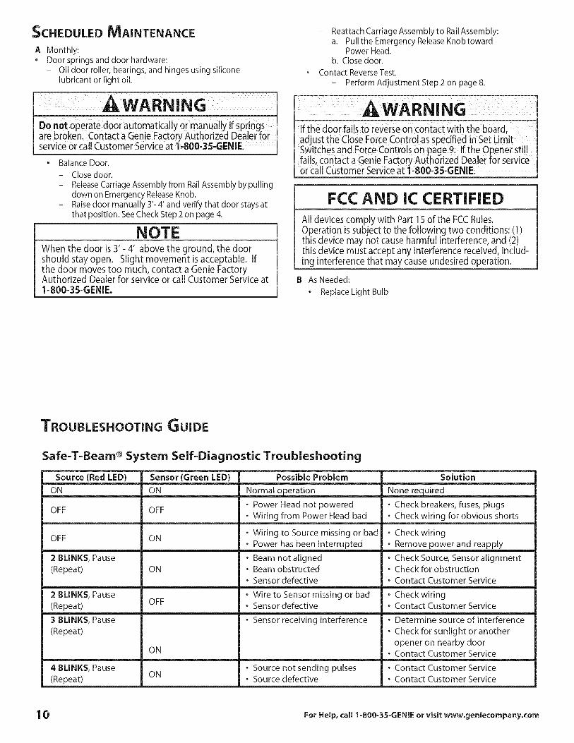
SCHEDULED MAINTENANCE
Ao
Monthly:Door springs and door hardware:- Oil door roller, bearings, and hinges using silicone
lubricant or light oil.
A WARNIN J--Do not operate door auto atiCally 0r man_al/y if Springsare broken, Contact a Genie Fact0ry Authorized Dealer forservice or call Customer Service at 1,800,35'GENIE. !
• Balance Door.
- Close door.
- ReleaseCarriage Assembly from Rail Assembly by pullingdown on Emergency Release Knob.
- Raisedoor manually 3'- 4' and verify that door stays atthat position. See Check Step 2 on page 4.
NOTEWhen the door is 3'- 4' above the ground, the doorshould stay open. Slight movement isacceptable. Ifthe door moves too much, contact a Genie FactoryAuthorized Dealer for service or call Customer Service at1=800=35=GENIE.
Reattach Carriage Assembly to Rail Assembly:a. Pull the Emergency Release Knobtoward
Power Head.b. Close door.
Contact Reverse Test,
- Perform Adjustment Step 2 on page 8.
AWARNINGIf the door fails to reverse on contact with the board,adjust the Close Force Control as specified in Set LimitSwitches and Force Controls on page 9. If the Opener stillfails, contact a Genie Factory Authorized Dealer for serviceor call Customer Service at 1-800-35-GENIE.
FCC AND IC CERTIFIEDAll devices comply with Part 15 of the FCCRules.Operation is subject to the following two conditions: (1)this device may not cause harmful interference,and (2)this device must accept any interference received, includ-ing interference that may cause undesired operation.
B As Needed:
• Replace Light Bulb
TROUBLESHOOTING GUIDE
Safe=T=Beam ® System Self=Diagnostic Troubleshooting
Source (Red LED)ON
OFF
OFF
2 BLINKS, Pause
(Repeat)
2 BLINKS, Pause(Repeat)
3 BLINKS, Pause(Repeat)
4 BLINKS, Pause
(Repeat)
Sensor (Green LED)
ON
OFF
ON
ON
OFF
ON
ON
Possible Problem
Normal operation
o Power Head not poweredo Wiring from Power Head bad
o Wiring to Source missing or bado Power has been interrupted
o Beam not alignedo Beam obstructed
o Sensor defective
o Wire to Sensor missing or bado Sensor defective
o Sensor receiving interference
. Source not sending pulses
. Source defective
Solution
None required
. Check breakers, fuses, plugs
. Check wiring for obvious shorts
. Check wiring
. Remove power and reapply
. Check Source, Sensor alignment
. Check for obstruction
. Contact Customer Service
o Check wiringo Contact Customer Service
o Determine source of interference
o Check for sunlight or another
opener on nearby door. Contact Customer Service
o Contact Customer Service
. Contact Customer Service
10 For Help, call 1=800-35-GENIE or visit www.geniecompany.com

Problem
Openerdoesnot runfrom WallControl
Door Opener startsfor no apparent reason
Door starts down, thenstops before it iscompletely closed
Door starts down, then
stops and goes backup
Door will only run closed
Doorwill onlyrunopen
Lights will not turn off
Door startsup,but stops beforeit iscompletelyopen
Operator runs, but doordoes not move
Wall ConsoleVacationLock function doesnot work
Noisy Operation
General TroubleshootingWhat To Do
1. Check Lock switch on Wall Control Installation Poster.2. Check Power Source:
• For Grounded Plug Connection.- Plug a lamp into the electrical outlet used for the door opener.
a. If lamp lights, power source is good.b. If lamp does not light, check fuse or circuit breaker.
• For Permanent Wiring Connection.- Check fuse or circuit breaker.
3. Check connections (see Wall Console Installation on Installation Poster):• At Power Head Terminals and Wall Control.
1. Check Wires to ensure that they are not cut (Staples can cut insulation and short Wires)Replace any shorting Staples and shorted Wires.
2. Was Remote Control lost or stolen? If so, erase all Remote Control codes from Receiver's memoryand reprogram for remaining remote controls. (See EraseAll Receiver Memory on page 8).
3. Ensure that no Buttons are stuck "pushed-in" on Wall Console or any Remote Controls.
1. Check Close Limit Switch setting (page 7 and poster). Adjust as needed.2. Check Force Setting (pages 7).Adjust as needed.3. Check for shorted wires.
1. Ifa new installation, check Door Arm position.2. Check operation of Contact Reversefunction.3. Check Safe-T-Beam®Systemfor beam obstruction or misalignment of Lenses.4. Check Safe-T-Beam®System diagnostic code.5. Check CloseForceadjustment (seeSet Limit Switchesand Force Controls on pages 7). Adjust as needed.6. Check garage door for binding.
1. Check Open Limit Switch for a short circuit and for proper wiring.2. Check Open Force adjustment (seeSetLimit Switches and ForceControls on pages 7). Adjust as needed.
3. Check condition of garage door and door spring(s).4. WARNING: If you suspecta problem with the garage door hardware or springs,contact a Genie
FactoryAuthorized Dealer for service,or contact Customer Serviceat 1-800-35-GENIE.
5. CheckPosition of LockSwitch on Console.
1. CheckSafe-T-Beam®Systemas detailed in the Safe-T-Beam®System Self-diagnosticTroubleshooting Chart(page 10).
2. CheckCloseLimit Switch for a short circuitand for proper wiring.3. CheckCloseForceadjustment (seeSet Limit Switchesand Force Controlson pages 7). Adjust asneeded.
1. Disconnect Wires connectingPushbutton to Power Head(seePushbutton Installation on poster).Checktheir conditionand either replaceor reconnect.
2. Until a replacement Wall Consolecan be obtained, disconnect Wall Consoleand useonly Remote Controlsor Wireless Keypadto operate Opener.
3. Check for non-compatible wall control.
1. Check (ensure) that garage door and Opener are in good repair, properly lubricated, and properlybalanced as detailed in Maintenance Section.
2. WARNING: If you suspecta problem with the garage door hardware or springs,contact a Genie FactoryAuthorized Dealer for service, orcontact Customer Serviceat 1-800-3S-GENIE.
3. CheckOpen Limit Switch for a short circuitand for proper wiring.4. CheckOpen Forceadjustment (seeSetLimit Switchesand ForceControlson pages 7). Adjust as needed.
1. EnsureCarriageAssembly is engaged to CarriageSlide (seeInstallCarriageAssemblyonto Railson InstallationPoster).2. CheckForceadjustment (seeSet Limit Switchesand Force Controlson pages 9 and 10). Adjust as needed.
1. EnsureCarriageAssembly is in contactwith CloseLimit Switch.2. Checkwhen door is fully closed,that Carriageactivates CloseLimit Switch. If not, adjust position of Close
Limit Switch (Seepages 7).
1. Be sure all fastenersare tight.2. Check (ensure) that garage door and Opener are in good repair, properly lubricated, and properly
balanced as described in Maintenance Section (page 10).
For Help, call 1-800-35-GENIE or visit www.geniecompany.com 11

PARTS iDENTIFICATION
Head List NumberPower Parts _.auded
[1] Power Head Assembly Item Part Name.1 Power Head Assembly 1
* 1A Cover (by Series Model) 1
* 1B Front Panel Assembly 1* 1D Motor Parts 1
* 1E Circuit Board Assembhz 1
* 1F Capacitor (By Series/Model) 1
1G Opto Wheel (not shown) 1
* 1H Carriage Slide 1* 1J Chain 1
1K Circuit Board Bracket 1
* 1L Drive Module 1
* 1M Terminal Strip 1
* 1N No. 8-32 x 3/4" Hex Head Screw
w/int. Lockwasher 1
1P Shock Absorption Stop 1
* 1Q Motor Mount Bracket (not shown', 1
1X Chassis 1
4 1/4-20 Shoulder Bolt 1
5 1/4" Flange Nut 139 Coupler 1
41 No. 8-32 x 3/8" PhillipsHex Head Screw 1
42 No. 8-32 x 3/8" PhillipsPan Head Screw 1
48 Mountinq Straps 2
49 Light Lens 1
* Pre-assembled
WIRING DIAGFIAM [ A Shut 0ff Cower bef0re 0penilg the cdver:[Components inside Cover May Cause Electric Shock J
RED
ORANGE
2
SEQUENCER HOUSING
, M°L°R.I I
, _,_I THERMAL _ _i:Y I [
] PROTECTOR [ "_ ,,,,,(::_ i [BLACK ' _ _'_/ I _ MOTOR
i I
;RED YELLOW',i jJ
POWER CORD
YELLOW YELLOW
z
/_7 _
®®®o6®®®@®®®
WHITE BLUE
LIGHT
POWERHEAD TERMINALS
WALLCONTROL
OPENLIMIT
COMMON
OPIN
IIM] SWITCH
(JO'lCLOSELIMIT
[_. LMIT SWTCH
12 For Help, call 1-800-35-GENIE or visit www.geniecompany.com
PARTS i DENTIFICATION
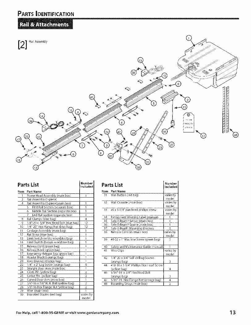
[2] RailAssembly
\
Parts Listitem Part Name
1 Power Head Assembly (main box)2 RailAssembly (1-piece)4 RailAssembly_3:piece)(main box)
5 First RailSection (separate box)6 Middle RailSection (separate box)7 End Rail section (separate box)
8 RailClamps (blue bag)9 1/4"-20x 5/8" HexHead Bolt (blue bag)
10 1/4"-20" Hex Flange Nut (blue bag)11 Carriage Assembly (main bag)12 RailStrap (blue bag)13 Limit Switch (white wire)(blue bag)14 Limit Switch (brown wire)(blue bag)15 ReleaseCord (green bag)16 ReleaseKnob (green bag)17 Emergency ReleaseTag (green bag)18 Header Bracket orange bag)20 Door Bracket (orange bag)22 1/4" x 2" Lag Screw (orange bag)23 Straight Door Arm (main box)24 ClevisPin (yellow bag)25 Cotter Pin (yellow bag)26 Curved Door Arm (main box)27 3/8"-16 x 7/8" H. H. Bolt (yellow bag)28 3/8"-16 Hex Nan e Nut ( ellow ba )29 Wire (main box)30 Insulated Staples(red bag)
m
1
I
I
I
I
4
12
12
I
I
I
I
I
I
I
I
I
8
I
2
2
I
2
2
I
variesbymodel
Parts Listitem Part Name
31 Wall Button (red bag)
32 Wall Console (main box)
33 #6 x 1-1/4" pan head phillips screw
34 Entrapment Warning Label (manual)35 Safe-T-Beam®Sensor (main box)36 Safe-T-Beam®Source (main box)37 Safe-T-BeaM®Mountinq Brackets38 Remote Controls (main box)
39 #8-32 x 1" Machine Screw (green bag)
40 Safety and Maintenance Guide (manual)41 Wire Clips
42 1/4"-20 x 3/4" Self-drilling Screws(orange bag)
44 #10-16 x 1-1/4" Phillips Hex Head Screw(yellow bag)
46 5/16"-18 x 3/4"Hex Head Bolt
(orange bag)47 5/16"-18 Hex Flange Nut (orange bag)48 Mounting Straps (main box)
m
variesbymodel
varies bymodel
varies bymodel
1112
varies bymodel
2
1varies bymodel
3
4
3
4
2
For Help, call 1-800-3S-GENIE or visit www.geniecompany.com 13
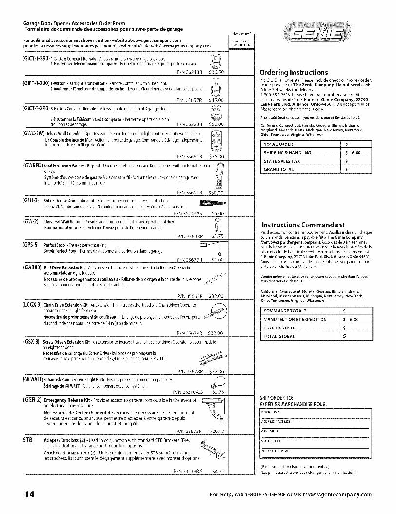
GarageDoorOpener AccessoriesOrder FormFormulairedecommandodesaccessoirespourouvre-porte degarage
For additional accessories not shown, visit our website at www.geniecompany.compour lesaccessoires suppl4mentaires pas montr4, visiter notr_ site web _ www.geniecompany.com
(GKT-1-390) 1-ButtonCompactRemote-Allowsremoteoperationofgaragedoor.1-BoutennerT_l_cornrnaadecornpacte- Permettreoperation_loign"deportedegarage.
P/N 36248R 536.50
(GiFT-I-390) 1-ButtonFlashlightTransmitter- RemoteControllerwithaFlashlight.1-houtenner['_rnetteurde[arnpedepoche- Lecontr61eur_loign_avecdelampedepoche.
P/N 35657R 545.00
{GICT-3-390)3-Bu_enCornpactBernete-AIIowsremoteoperationof3garagedoors.
3=boutennerlaT_l_cornrnandecornpacte- Permettreoperation _loign'troisportes de ara e. P/N 36223R 550.00
(GWC-2W) Deluxe Wall Console - OperatesGarageDoor.Independent light control. Securityvacation lock.
LaConsole dseluxe de Mur- Actionnela porte degarage.Commanded'_clairageind_pendante.Interrupteurde verrouillagede s_curit&
P/N 35661R 535.00
(GWKPD)DualFrequencyWirelessKeypad-OperatesIntellicode'GarageDoorOpenerswithoutRemoteControlorkey.Syst_rned'ouvre-pertedegarage_ claviersansfil- Actionnelesouvre-portedegarageavecIntellicode'sanst_l_commandenicl&
(GLU-3)550.00
55.00
(Gw-2)
(6PS-5)
P/N 35691 R
3/4 oz. ScrewDrive Lubricant - Ensuresproperequipment wearprotection.
Laonza3/4 Lubricantde la vis - Garantircomponantexactparsyst_med_fenseversuser.
P/N 35218AS
Universal Wall Button- Providesadditional convenientinsideoperation of door.
Bouten mural universal - ActionneI'ouvre-portede I'int_rieurdu garage.
Perfect Step- Ensuresperfectparking.
Butoir Perfect Stop- Permetde stationner_ laperfectiondans legarage.
(GABXS)
P/N 35693R 53.75
P/N 35677R 54.00
BeltDriveExtensionKit-AnExtensionthatincreasesthe travelofa beltdrivenOpenertoaccommodateaneightfootdoor.N_cessairede prolongernentdu coulisseau-Rallongedeprolongeantlacoursederouvre-porteBeltDrivepouruneportede2,4m(8pi)dehauteur.
P/N 35663R
(LCGX-8) Chain Drive ExtensionKit- An Extensionthat increasesthe travelof a ChainDrivenOpenerto
accommodateaneight foot door.
N@cessairede prolongernent du coulisseau - Rallongedeprolongeantlacoursede rouvre-porte
du conduitdechainpour une portede2,4m (8pi) dehauteur.
532.00
P/N 35679R 532.00
(GSX-8) ScrewDriven Extension Kit - AnExtensionto increasetravel of ascrewdriven Operatorto accommodate
an eight foot door.
N_cessairede taffonge du Screw Drive- Rallongede prolongeant lacoursedeI'ouvre-portepour une porte de 2,4m (8pi) de hauteur.(GIRU-lT) _-e_
(60WATT)Enhanced/RoughServiceLightBulb-Ensuresproperequipmentcompatability.
(GER-2)
P/N 35678R
Eclairagede 50 WATT- Garantircomponantexactpar syst_me.
P/N 26210A.S
Emergency Release Kit - Provides access to garage from outside in the event ofan electrical power failure.
N6cessaires de D4clenchement de secours - Le n_cessaire de d_clenchement
de secours est con_upour vous permettre d'acc4der & votre garage depuisI'ext_rieur en cas de panne de courant et Iorsqu'il.
P/N 35675R
532.00
52.73
520.00
STB Adapter Brackets (2) - Used in conjunction with standard STBBrackets. Theyprovide additional clearance and mounting options.
Crochets d'adaptateur (2) - Utilis_ conjointement avec STBstandard reenterles crochets, ils fournissent le d_gagement suppl_mentaire avec monter d'options.
P/N 34439R.S 54.37
How many?
Comment
beaucoup?
Ordering InstructionsNo C.O.D.shipments. Please include check or money order,made payable to The Genie Company. Do not send cash.Allow 3-4 weeks for delivery.1-800-354-3643. Please have part number and creditcard ready. Mail Order Form to: Genie Company, 22790Lake Park Blvd, Alliance, Ohio 44601. We accept Visa orMastercard on phone orders only.
Please add local sales tax if you reside in one of the states listed.
Californla, Connecticut, Florida, Georgia, Illinois, Indiana,
Maryland, Massachusetts, Michigan, New Jersey, New York,
Ohio, Tennessee, Virginia, Wisconsin
TOTAL ORDER $
SHIPPING & HANDLING $ 6.00
STATE SALESTAX $
GRAND TOTAL $
Instructions CommandantPasd'exp_dition centre remboursement.Veuillezinclure un chequeou un mandat bancaire,le payablefait aThe Genie Company.N'envoyez pasd'argent comptant. Accordezde 3 _4 semainespour la livraison.1-800-354-3643.Ayezsousla main le num6rode lapieceet celui de lacartede credit.Mettre _ la paste learrngement_:GenieCompany,22790 LakePark Bivd, Alliance, Ohio 44601.Nousacceptonslescommandespar t_l@hone avec paiementparcartede creditVisaou Mastercard.
Veuillez indiquer les taxes de vente locales si vous r4sidez dans I'un des
_tats r4pertori4s ¢i-dessous.
California, Connecticut, Florida, Georgia, Illinois, Indiana,
Maryland, Massachusetts, Michigan, New Jersey, New York,
Ohio, Tennessee, Virginia, Wisconsin
COMMANDETOTALE $
MANUTENTIONETEXPEDITION $ 6.00
TAXEDEVENTE $
TOTALGLOBAL $
SHIP ORDER TO:
EXPEDIER MARCHANDISE POUR:
NAME / NOV
ADDRESS / ADRESSE
CITY / VILLE
STATE / ETAT
ZIP / CODE POSTAL
(Pricessubject to change without notice)
(Lesprix assujettissentpour changer sansla notification)
14 For Help, call 1=800=35=GENIEor visit www.geniecompany.com