Embed Size (px)
Citation preview
GANDALF
A computer code for quench analysisof dual flow CICC’s
Version 2.2
by CryoSoft
January 2001
5,rue de la BeletteF-01710 THOIRY, France
e-mail: [email protected]

2 GANDALF - A computer code for quench analysis of dual flow CICC’s
© CryoSoft, 2001
DISCLAIMER
Even though CryoSoft has carefully reviewed this manual, CRYOSOFTMAKES NO WARRANTY, EITHER EXPRESSED OR IMPLIED, WITH RESPECT TOTHIS MANUAL, ITS QUALITY, ACCURACY, MERCHANTABILITY, OR FITNESSFOR A PARTICULAR PURPOSE. AS A RESULT, THIS MANUAL IS PROVIDED “ASIS”, AND YOU, THE PURCHASER, ARE ASSUMING THE ENTIRE RISK AS TO ITSQUALITY AND ACCURACY.
IN NO EVENT WILL CRYOSOFT BE LIABLE FOR DIRECT, INDIRECT, SPECIAL,INCIDENTAL, OR CONSEQUENTIAL DAMAGES RESULTING FROM ANY DEFECTOR INACCURACY IN THIS MANUAL, even if advised of the possibility of suchdamages.
Copyright ” 1996-2002 by CryoSoft

GANDALF - A computer code for quench analysis of dual flow CICC’s 3
© CryoSoft, 2001
INTRODUCTION............................................................................................................. 4
CODE STRUCTURE ........................................................................................................ 7
MAIN SOLVER ................................................................................................................. 7POST PROCESSOR.............................................................................................................. 7MATERIAL PROPERTIES...................................................................................................... 8
INPUT VARIABLES......................................................................................................... 9
EXTERNAL ROUTINES ................................................................................................ 20
CROSS SECTIONS ............................................................................................................ 20COIL CURRENT .............................................................................................................. 22MAGNETIC FIELD........................................................................................................... 23EXTERNAL HEAT INPUT................................................................................................... 24EXTERNAL BOUNDARY CONDITIONS .................................................................................. 25USER’S DEFINED MESH..................................................................................................... 26ELECTRICAL AND THERMAL PROPERTIES OF USER’S DEFINED MATERIALS ................................... 27
Density ..................................................................................................................... 27Specific heat .............................................................................................................. 27Thermal conductivity................................................................................................... 28Electrical resistivity .................................................................................................... 28Critical current density ............................................................................................... 29Critical temperature ................................................................................................... 29Current sharing temperature........................................................................................ 29
FRICTION FACTOR .......................................................................................................... 30HEAT TRANSFER COEFFICIENT........................................................................................... 31
Conductor-bundle heat transfer coefficient...................................................................... 31Conductor-jacket equivalent heat transfer coefficient ........................................................ 31Jacket-bundle wall equivalent heat transfer coefficient ...................................................... 32Hole-bundle mixing heat transfer coefficient.................................................................... 32
QUALITY INDICATORS AND GENERAL GUIDELINES FOR RUNNING....................... 34
ERROR CODES............................................................................................................. 36
POST PROCESSING...................................................................................................... 40
COMMAND LANGUAGE FOR THE POST PROCESSORS................................................................ 40
REFERENCES............................................................................................................... 45
EXAMPLES................................................................................................................... 46
INPUT FOR THE FIRST RUN WITH GANDALF ........................................................................ 46INPUT FOR THE RESTART WITH GANDALF.......................................................................... 47INPUT FOR THE POST PROCESSOR GANDALF_POST.............................................................. 47

4 GANDALF - A computer code for quench analysis of dual flow CICC’s
© CryoSoft, 2001
Gandalf ! If you had heard only a quarter of whatI have heard about him, and I have only heard verylittle of all there is to hear, you would be prepared forany sort of remarkable tale.
(J.R.R.Tolkien, The Hobbit)
Introduction
GANDALF is the numerical implementation of a 1-D model for the simulation of quench initiationand quench propagation in CICC's with cooling channels. The model is described extensively in Refs.[1,2], together with the details on the numerical method (see also [3] and [4]). The basic conductorscheme modelled is reported in Fig. 1. The 1-D model consists of a maximum of four independentcomponents at different thermodynamic states:
• the strands, consisting of stabilizer and superconductor,• the conduit, grouping the jacket and insulation,• the bundle helium, surrounding the strands in the cable, and• the hole helium, flowing in an independent cooling passage.
The temperatures of these four components are treated separately and the energy balances are coupledthrough heat transfer coefficients at the contact (wetted) surfaces. With respect to the helium flow,Gandalf can treat single phase supercritical and superfluid compressible helium flow. The model takesinto account the presence of two separate flows at different thermodynamic state (i.e. pressure andtemperature) and velocity. The two flows are assumed to take place in the intersticial spaces of thecable bundle (as for standard CICC's) and in a separate cooling hole. The helium in the bundle and inthe hole exchange mass and momentum in addition to energy. Note that it is possible, by setting thehole area to zero, to suppress the hole flow and to solve a simplified model for a CICC without centralcooling hole. In this case Gandalf effectively eliminates the equations that are not necessary, thusavoiding unnecessary CPU and memory overheads.
The conductor length, or flow path, is modelled along its length using linear finite elements. At eachnode 8 degrees of freedom are defined, i.e. the temperature of strands and conduit, and the twotemperatures, pressures and velocities of the bundle and hole helium. A schematic view of the finiteelement is given in Fig. 2, where the thermal couplings are evidenced and the dof's are indicated.
The boundary conditions at the ends of the flow paths are assumed to be given for the helium either byreservoirs with specified pressure and temperature or by closed valves (i.e. no flow). The conductor endsare assumed adiabatic. In case of helium superfluid the boundary temperature is prescribed.
Operating current and magnetic field can be arbitrarely specified as a function of time and position (forthe field)
An external heat source in the strands or in the conduit, user's specified, initiates the quench. The Jouleheat generation is computed consistently with the non-linear critical current density relation. Theelectric field in the superconductor at the resistive transition is modelled using a power law dependence,which can be reduced to the limit of infinitely sharp transition. The Joule heat is distributed resistivelyamong strands and conduit (this feature is useful for low-resistance conduits such as, e.g., Aluminium).
Additional features of the numerical implementation of GANDALF are automatic mesh size and timestep adaptivity. The mesh is refined or coarsened among a minimum and a maximum element size

GANDALF - A computer code for quench analysis of dual flow CICC’s 5
© CryoSoft, 2001
specified by the user following the evolution of the normal fronts in the flow path, by means of a fronttracking procedure. The time step is adapted in order to satisfy an a priori relative accuracy criterionbased on a simplified model equation and the amplificaton factor of the time integration scheme. At themoment two options (to be selected by the user) are programmed for the integration method: a secondorder accurate algorithm for higher accuracy but subject to the possibility of oscillations in thesolution, and a first order algorithm which damps the oscillations, with a higher numerical stability,but lower accuracy. Details on the numerics are again given in [1].
The present version of GANDALF computes some error and quality indicators for the solutionobtained. They are based on variables interpolation, numerical diffusivity and additional numericalpropagation. The user must use this information to check that the solution is numerically converged.In other words, the trade-off between CPU cost and solution quality is left to the user. Later we dealwith the meaning of the error and quality indicators and we give guidelines for judging the quality of asolution.
The solver decides whether a quench or a recovery has taken place. In particular, the algorithm for thedecision is based on the total Joule heating in the conductor length analysed. The decision is taken atthe last step in the following way:
if (time £ 2 * heating_time or d( Joule_heating)/dt < 0) thentransient in process
elseif(time > 2*heating_time and Joule_heating = 0) thenrecovery
elseif(time > 2*heating_time and Joule_heating > 0) thenquench
endif
This insures that no decision on recovery and quench is taken before the heating is off, and until thejoule heating is growing. Note that, as explained in the description of the input parameters, the heatingtime TAUQ is used for the tests above. This implies that, in the case that the user defines the heatingthrough an external routine, the value of the heating time must still be set if a meaningful decision onrecovery/quench is desired. A message is output at the end of the run in the log file, indicating theevent that has been recognized based on the decision-taking procedure given above. The possible eventsare:
“Transient still in process”“The conductor has recovered”“The conductor is quenching”

6 GANDALF - A computer code for quench analysis of dual flow CICC’s
© CryoSoft, 2001
Figure 1. Typical geometry of a CICC with central cooling hole as modelled in GANDALF.
conduit (jacketand insulation)Tjk
strands (superconductor,stabilizer)Tst
hole heliumTH, pH, vH
bundle heliumTB, pB, vB
multi-dofnode
pcj hcj
pc hc
pj hj
phb hhb
bundle flow
hole flow
mixing flow
Figure 2. Basic finite element used in GANDALF, showing the degrees of freedom and thethermal and flow coupling among components.

GANDALF - A computer code for quench analysis of dual flow CICC’s 7
© CryoSoft, 2001
Code Structure
Main solver
This is the portion performing the calculation and generating the results. The code performs input andoutput on the following units
File Name Usage
input file Input of the data for the rungandalf.store Storage for restart and post-processinggandalf.output Output of the results
Units 5 and 6 are attached to the terminal and are used for debugging or monitoring purposes. Gandalfrequires a single interactive input, the file name where the input data is located. The results are outputin ASCII format and as binary storage, this last is used either for restarts (recovering the results up tothe last time stored) or for post-processing (see later for a description).
Note: FORTRAN unit numbers above 50 are reserved for internal use
Post processor
After a run it is possible to plot or print tables of the results stored on the binary filegandalf.store using the dedicated post-processor. The post-processor reads the binary data and asequence of commands. Each command is executed in sequence and causes the generation of PostScriptplots or tables of selected data. The post-processor performs input and output on the following units
File Name Usage
gandalf.store Data stored, read-in for post-processingcommand file ASCII sequence of commands determining the generation of plots or tables.
The commands are read sequentially and executedg1dp.tables ASCII file with table of results, generated by the post-processor following
the commands read from command.filePostScript.ps Plots in PostScript format, generated by the post-processor following the
commands read from command.file
Units 5 and 6 are attached to the terminal and are used for debugging or monitoring purposes.
Note: FORTRAN unit numbers above 50 are reserved for internal use

8 GANDALF - A computer code for quench analysis of dual flow CICC’s
© CryoSoft, 2001
Material properties
The main solver needs to be linked to a set of routines for the calculation of the material properties ofsolid materials and helium. As these routines are at the lowest level in the code execution, theirefficiency is of paramount importance. A set of routines is provided by default with the program. Thesecan be easily changed provided that the calling arguments are respected (and obviously units !) andkeeping in mind the requirements on the code efficiency. For the complete list of the propertyfunctions, please refer to the manuals of the libraries Solid and He_table of CryoSoft.

GANDALF - A computer code for quench analysis of dual flow CICC’s 9
© CryoSoft, 2001
Input Variables
The following table contains the input variables, their physical dimensions, default value and meaningfor the GANDALF processor. The input of GANDALF is done using the FORTRAN instructionNAMELIST. The namelist is called INDATA. A sample input file is reported in the end of the manual.Note the first line in the input file, read-in as the problem title.
Conductor cross section composition and propertiesVariable Type Units Default Meaning
ICBFUN I (-) 0 Flag used to set the geometry of the cable crosssection as a function of position along the length
(-1) user’s defined through external functionEXTCAB to be linked with the code
( 0) constant, as specified through input
ASC R (m2) 0.0 Superconductor cross section
AST R (m2) 0.0 Stabilizer cross section
AJK R (m2) 0.0 Jacket (conduit) cross section
AIN R (m2) 0.0 Insulation cross section
ISC I (-) 0 Flag used to define the superconductor type:(<0) user’s defined. In this case all
thermophysical and electrical propertiesare provided through external functionsUserDensity, UserSpecificHeat,UserConductivity, UserCurrentSharing,UserCriticalTemperature andUserCriticalCurrent to be linked withthe code
( 0) None(31) standard NbTi(32) standard Nb3Sn
IST I (-) 0 Flag used to define the stabilizer material:(<0) user’s defined. In this case all
thermophysical and electrical propertiesare provided through external functionsUserDensity, UserSpecificHeat,UserConductivity and UserResistivityto be linked with the code
( 1) Copper( 2) Aluminium
IJK I (-) 0 Flag used to define the jacket material:

10 GANDALF - A computer code for quench analysis of dual flow CICC’s
© CryoSoft, 2001
(<0) user’s defined. In this case allthermophysical and electrical propertiesare provided through external functionsUserDensity, UserSpecificHeat,UserConductivity and UserResistivityto be linked with the code
( 1) Copper( 2) Aluminium( 3) Titanium(11) Copper-Nickel(13) Stainless Steel(14) Inconel(15) Incoloy 908
IIN I (-) 0 Flag used to define the insulating material:(<0) user’s defined. In this case all
thermophysical properties are providedthrough external functions UserDensity,UserSpecificHeat and UserConductivityto be linked with the code.
(21) Epoxy Resin(22) Glass-Epoxy(23) Polyimide (Kapton)
EPSLON R (-) 0.0 Total longitudinal strain in the superconductor inoperating condition. Strain is assumed constantduring the transient
E0 R (V/m) 0.0 Electric field criterion for the definition of theresistive transition at the critical current. E0 isneeded if the user chooses to model the electricfield E in the superconductior by the powerlaw: E = E0
IIc
Ê
Ë Á ˆ
¯ ˜
n
, where I is the current in the
superconductor and Ic is the critical current. Thismodel is used for a choice of NPOWER below 250(see below).
NPOWER I (-) 0 Exponent of the power-law used to model thelongitudinal electric field in the superconductor(see above). The power law is used only for valuesof 0 < NPOWER £ 250. For NPOWER > 250 asharp transition is assumed (zero resistance belowIc, infinite resistance above Ic), which does notrequire the definition of E0.
RRR R (-) 0.0 Residual resistivity ratio for stabilizer material
ICHFUN I (-) 0 Flag used to set the geometry of the heliumchannels as a function of position along the length
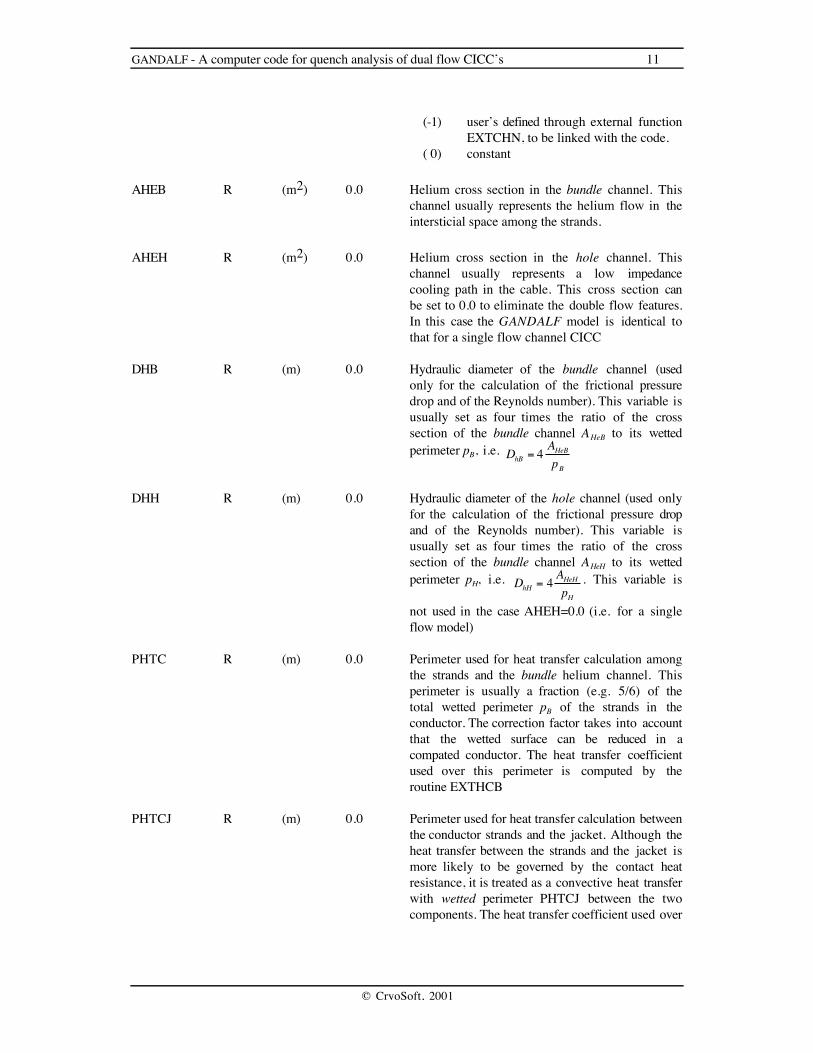
GANDALF - A computer code for quench analysis of dual flow CICC’s 11
© CryoSoft, 2001
(-1) user’s defined through external functionEXTCHN, to be linked with the code.
( 0) constant
AHEB R (m2) 0.0 Helium cross section in the bundle channel. Thischannel usually represents the helium flow in theintersticial space among the strands.
AHEH R (m2) 0.0 Helium cross section in the hole channel. Thischannel usually represents a low impedancecooling path in the cable. This cross section canbe set to 0.0 to eliminate the double flow features.In this case the GANDALF model is identical tothat for a single flow channel CICC
DHB R (m) 0.0 Hydraulic diameter of the bundle channel (usedonly for the calculation of the frictional pressuredrop and of the Reynolds number). This variable isusually set as four times the ratio of the crosssection of the bundle channel AHeB to its wettedperimeter pB, i.e. DhB = 4 AHeB
pB
DHH R (m) 0.0 Hydraulic diameter of the hole channel (used onlyfor the calculation of the frictional pressure dropand of the Reynolds number). This variable isusually set as four times the ratio of the crosssection of the bundle channel AHeH to its wettedperimeter pH, i.e. DhH = 4 AHeH
pH
. This variable is
not used in the case AHEH=0.0 (i.e. for a singleflow model)
PHTC R (m) 0.0 Perimeter used for heat transfer calculation amongthe strands and the bundle helium channel. Thisperimeter is usually a fraction (e.g. 5/6) of thetotal wetted perimeter pB of the strands in theconductor. The correction factor takes into accountthat the wetted surface can be reduced in acompated conductor. The heat transfer coefficientused over this perimeter is computed by theroutine EXTHCB
PHTCJ R (m) 0.0 Perimeter used for heat transfer calculation betweenthe conductor strands and the jacket. Although theheat transfer between the strands and the jacket ismore likely to be governed by the contact heatresistance, it is treated as a convective heat transferwith wetted perimeter PHTCJ between the twocomponents. The heat transfer coefficient used over

12 GANDALF - A computer code for quench analysis of dual flow CICC’s
© CryoSoft, 2001
this perimeter is computed by the routineEXTHCJ
PHTJ R (m) 0.0 Perimeter used for heat transfer calculation betweenthe jacket and the bundle helium channel. The heattransfer coefficient used over this perimeter iscomputed by the routine EXTHJB
PHTHB R (m) 0.0 Perimeter used for heat transfer calculation betweenthe bundle and the hole helium channels. Thisperimeter is typically the physical perimeter of thepipe wall separating the two flows. In the case ofabsence of physical wall the perimeter PHTHB isan imaginary boundary that separates the twoparallel channels. The heat transfer coefficient usedover this perimeter is computed by the routineEXTHHB
PERFOR R (-) 0.0 Percentage perforation of the separation perimeterbetween the bundle and hole helium channelsPHTHB. This factor, between 0 and 1, describesthe transverse permeability of the hole-bundleinterface. A value of 1 implies that the wholeperimeter PHTHB is transparent to transverse flow(i.e. no physical wall), a value of 0 means notransverse flow (i.e. a continuous physical wall).

GANDALF - A computer code for quench analysis of dual flow CICC’s 13
© CryoSoft, 2001
Operating currentVariable Type Units Default MeaningIOP0 R (A) 0.0 Initial operating current in the coil
IOPFUN I (-) 0 Flag used to specify the behaviour of the operatingcurrent in time:
(-1) user’s defined. through external functionEXTI to be linked with the code
( 0) constant in time( 1) exponential decay with time constant
TAUDUM after a delay TAUDET
TAUDET R (s) 0.0 If IOPFUN=1 determines the delay betweeninitiation of the transient anmd the sitching actionto dump the coil. The current is constant for 0 < t< TAUDET
TAUDUM R (s) 0.0 In the case IOPFUN=1 determines the timeconstant of the dump of the current (starting afterTAUDET seconds with exponential law in time).For t > TAUDET the current is given by:IOP = IOP0 * exp((t-TAUDET)/TAUDUM)

14 GANDALF - A computer code for quench analysis of dual flow CICC’s
© CryoSoft, 2001
Operating magnetic fieldVariable Type Units Default MeaningIBIFUN I (-) 0 Flag used to specify the behaviour of the magnetic
field in time and space(-1) user’s defined, through external function
EXTB to be linked with the code( 0) constant in time and linear in space
between the values BISS and BOSS atinlet and outlet respectively
( 1) Current related decay in time of a lineardistribution in space. The lineardistribution at any time is the sum ofthe steady state distribution determinedas for IBIFUN=0 (between BISS andBOSS) and of a transient distributionproportional to the operating currentbetween the values BITR and BOTR atinlet and outlet respectively
BISS R (T) 0.0 Value of the steady state component of themagnetic field at the coil inlet
BOSS R (T) 0.0 Value of the steady state component of themagnetic field at the coil outlet
BITR R (T) 0.0 Value of the transient component of the magneticfield at the coil inlet
BOTR R (T) 0.0 Value of the transient component of the magneticfield at the coil outlet

GANDALF - A computer code for quench analysis of dual flow CICC’s 15
© CryoSoft, 2001
Initial and boundary conditionsVariable Type Units Default MeaningINTIAL I (-) 0 Flag used to specify the initial and boundary
conditions for the transient. An approximate initialcondition is computed in the case of initial flow.In the case of variable boundary conditions theexternal function EXTR is called to set theboundary pressure and temperature as a function oftime. The type of boundary condition selected isindicated in the output file as input echo.
( 0) user’s defined, through external functionEXTA to be linked with the code
( 1) inlet and outlet pressure and inlettemperature are given. The initial flowand variable distribution are computedfrom the pressure drop. The boundariesfor the flow are at constant pressure andtemperature (as established from theinitial distribution)
(-1) as for (1) but boundary pressure andtemperature can be variable in time atinlet and outlet through the user routineEXTR
( 2) inlet pressure, temperature andmassflow are given. The initial flowand variable distribution are computedfrom the inlet pressure and mass flow.The boundaries for the flow are atconstant pressure and temperature (asestablished from the initial distribution)
(-2) as for (2) but boundary pressure andtemperature can be variable in time atinlet and outlet through the user routineEXTR
( 3) inlet pressure, and temperature aregiven, the outlet is closed. The initialdistribution is of zero flow and constant p,T. The boundary conditions areconstant pressure and temperature at theinlet and closed outlet. This choicesimulates a symmetry at the outlet
(-3) as for (3) but boundary pressure andtemperature can be variable in time atinlet through the user routine EXTR
( 4) initial pressure and temperature given,closed system assumed. The initial distribution is of zero flow and constantp,T along the flow path. The boundaryconditions are of closed inlet and outlet

16 GANDALF - A computer code for quench analysis of dual flow CICC’s
© CryoSoft, 2001
PREINL R (Pa) 0.0 He pressure at the flow path inlet, used in the caseINTIAL=1, INTIAL=2 and INTIAL=3
PREOUT R (Pa) 0.0 He pressure at the flow path outlet, used in thecase INTIAL=1 only. Computed in the caseINTIAL=2 (specified massflow).
TEMINL R (K) 0.0 He temperature at the flow path inlet, used in thecases INTIAL=1, INTIAL=2 and INTIAL=3. Notethat in the two cases INTIAL=1 and INTIAL=2 theinlet reservoir has a temperature equal to TEMINLonly for positive massflow (inlet to outlet). In thecase of negative massflow (outlet to inlet) the inletreservoir has temperature equal to TEMOUT.
TEMOUT R (K) 0.0 He temperature at the flow path outlet, used in thecases INTIAL=1 and INTIAL=2. Note that theoutlet reservoir has a temperature equal toTEMOUT only for negative massflow (outlet toinlet). In the case of positive massflow (inlet tooutlet) the outlet reservoir has temperature equal toTEMINL.
MDTINL R (Kg/s) 0.0 He massflow at the flow path inlet, used in thecase INTIAL=2. Computed in the case INTIAL=1(specified pressure drop)
PREINI R (Pa) 0.0 He initial pressure in the flow path used in thecase INTIAL=4
TEMINI R (K) 0.0 He initial temperature in the flow path used in thecase INTIAL=4

GANDALF - A computer code for quench analysis of dual flow CICC’s 17
© CryoSoft, 2001
External heatingVariable Type Units Default MeaningIQFUN I (-) 0 Flag used to specify the heating input
(-1) user’s defined, through external functionEXTQ to be linked with the code
( 0) square wave in space and time. Thepower Q0 per unit length is input for atime TAUQ in the region XQBEG < x< XQEND
Q0 R (W/m) 0.0 Linear heat flux input in the conductor whenIQFUN=0
TAUQ R (s) 0.0 Heating time when IQFUN=0. The power isapplied for 0 < t < TAUQ. Note that TAUQ isused in any case for the decision on recovery orquench in a transient. Therefore if a meaningfuldecision is requiored, the user must set it even inthe case that the ehating is defined through theexternal routine EXTQ. Its meaning in this case isthe time after which all heating fluxes are zero.
XQBEG R (m) 0.0 For IQFUN=0 beginning of the heated region
XQEND R (m) 0.0 For IQFUN=0 end of the heated region

18 GANDALF - A computer code for quench analysis of dual flow CICC’s
© CryoSoft, 2001
Mesh and time stepping definitions. Operation flagsVariable Type Units Default Meaning
NELEMS I (-) 0 Total number of elements in the mesh
XLENGT R (m) 0.0 Total length of the cooling channel
ITYMSH I (-) 0 Flag used to specify the mesh type. Static (i.e.non-adaptive) and dynamic (i.e. adaptive) meshescan be requested)
(-1) user’s defined, the mesh is set in theexternal function EXTM (to be linkedwith the code) at each time step. Theuser is requested to adapt the mesh (ifdesired and necessary)
( 0) stayic uniform spacing in the lengthXLENGT with NELEMS elements.
( 1) static locally refined in the regionXBREFI < x < XEREFI. A total ofNELEMS elements are generated in thecooling path of length XLENGT, ofwhich NELREF are in the refinedregion.
( 2) dynamic (adaptive) with initial uniformspacing in the length XLENGT withNELEMS elements. The mesh isadaptive with minimum and maximummesh sizes determined by the SIZMINand SIZMAX parameters
( 3) dynamic (adaptive) with initial localrefinement in the region XBREFI < x <XEREFI. A total of NELEMS elementsare generated in the cooling path oflength XLENGT, of which NELREFare in the refined region. The mesh isadaptive with minimum and maximummesh sizes determined by the SIZMINand SIZMAX parameters
XBREFI R (m) 0.0 Beginning of the initial (t=0) refinement region
XEREFI R (m) 0.0 End of the initial (t=0) refinement region
NELREF I (-) 0 Number of elements in the refined region. It islimited by the total number of element in the flowpath as follows:
NELREF < NELEMS-2

GANDALF - A computer code for quench analysis of dual flow CICC’s 19
© CryoSoft, 2001
SIZMIN R (m) 0.0 minimum allowed element size (this is theelement size used in the vicinity of the normalfronts)
SIZMAX R (m) 0.0 maximum allowed element size. Note hat anyinitial element longer than SIZMAX will beautomatically refined during the time stepping
METHOD I (-) 0 Flag used for the selection of the time integrationmethod and space upwind
( 0) a globally first order accurate (in spaceand time) method is used (smooth butless accurate answers)
( 1) a globally second order accurate (inspace and time) method is used (sharperfront resolution, but it is possible thatwiggles are created at the fronts)
TEND R (s) 0.0 Final time for the time integration
STPMIN R (s) 0.0 minimum allowed time step
STPMAX R (s) 0.0 maximum allowed time step
PSTEP R (s) 0.0 print-out time step. The output to gandalf.outputoutput every PSTEP seconds of real time
GSTEP R (s) 0.0 storage time step. The output to gandalf.store(storage for post-processing and restart) is outputevery GSTEP seconds of real time
IRESTA I (-) 0 Flag used to indicate the run type( 0) first run. All variables are set( 1) restart run. The last time step stored is
recovered from gandalf.store
ISTORP I (-) 0 Flag to require the storage of the results eachGSTEP seconds of real time
( 0) no storage performed. WARNING: inthis case neither post-processing, norrestarting is possible
( 1) storage performed
MONITR I (-) 0 Flag activating the interactive monitor for on-linevisualization of the dynamics (experimentalfeature)
( 0) no interactive monitor( 1) ineractive monitor

20 GANDALF - A computer code for quench analysis of dual flow CICC’s
© CryoSoft, 2001
External Routines
The following sections describe routines that are provided as an interface for the user to improve themodelling capabilities of GANDALF. These routines are either provided as dummy (void) procedures,in the case that they are not needed for the standard execution of the code, or contain general purposerelations (such as the case for EXTF for the friction factor and the routines of the EXTHxx series forthe heat transfer coefficients) in the case that they are used in the standard code execution.
Note : FORTRAN unit numbers above 50 are reserved for internal use
Cross sections
SUBROUTINE EXTCAB (NOD ,X ,ASC ,AST ,AJK ,AIN , PHTC ,PHTJ ,PHTCJ ,ASC_X ,AST_X ,AJK_X , AIN_X ,PHTC_X,PHTJ_X,PHTCJ_X)
Returns the cable cross sections and wetted perimeter as a function of the position along the cable
List of variables:
Variable Type I/O Units MeaningNOD I I (-) Node numberX R I (m) Nodal coordinateASC R I (m2) Superconductor cross section (as from input)AST R I (m2) Stabilizer cross section (as from input)AJK R I (m2) Jacket cross section (as from input)AIN R I (m2) Insulation cross section (as from input)PHTC R I (m) Heat transfer perimeter at the contact surface of the
conductor and bundle helium channel (as frominput)
PHTJ R I (m) Heat transfer perimeter at the contact surface of thejacket and bundle helium channel (as from input)
PHTCJ R I (m) Heat transfer perimeter at the contact surface of theconductor and jacket (used to model the contactresistance) (as from input)
ASC_X R O (m2) Superconductor cross section at node NODAST_X R O (m2) Stabilizer cross section at node NODAJK_X R O (m2) Jacket cross section at node NODAIN_X R O (m2) Insulation cross section at node NODPHTC_X R O (m) Heat transfer perimeter at the contact surface of the
conductor and bundle helium channel at node NODPHTJ_X R O (m) Heat transfer perimeter at the contact surface of the
jacket and bundle helium channel at node NODPHTCJ_X R O (m) Heat transfer perimeter at the contact surface of the
conductor and jacket (used to model the contactresistance) at node NOD

GANDALF - A computer code for quench analysis of dual flow CICC’s 21
© CryoSoft, 2001
SUBROUTINE EXTCHN (NOD ,X ,AHEH ,AHEB ,DHH ,DHB , PHTHB ,PERFOR,AHEH_X,AHEB_X,DHH_X ,DHB_X , PHTHB_X,PERFOR_X)
Returns the channel cross sections, hydraulic diameter, wetted perimeter between channels andperforation as a function of the position along the cable
List of variables:
Variable Type I/O Units MeaningNOD I I (-) Node numberX R I (m) Nodal coordinateAHEH R I (m2) Cross section of the hole helium channel (as from
input)AHEB R I (m2) Cross section of the bundle helium channel (as
from input)DHH R I (m) Hydraulic diameter of the hole helium channel (as
from input)DHB R I (m) Hydraulic diameter of the bundle helium channel
(as from input)PHTHB R I (m) Heat transfer perimeter at the contact surface of the
hole and bundle helium channels (as from input)PERFOR R I (m) Percentage perforation of the wetted perimeter
between hole and bundle helium channels (as frominput)
AHEH_X R O (m2) Cross section of the hole helium channel at nodeNOD
AHEB_X R O (m2) Cross section of the bundle helium channel at nodeNOD
DHH_X R O (m) Hydraulic diameter of the hole helium channel atnode NOD
DHB_X R O (m) Hydraulic diameter of the bundle helium channel atnode NOD
PHTHB_X R O (m) Heat transfer perimeter at the contact surface of thehole and bundle helium channels at node NOD
PERFOR_X R O (m) Percentage perforation of the wetted perimeterbetween hole and bundle helium channels at nodeNOD

22 GANDALF - A computer code for quench analysis of dual flow CICC’s
© CryoSoft, 2001
Coil current
SUBROUTINE EXTI (TIME ,TSTEP ,IOP0 ,RSSTNC,IOP )
Compute the operating current as an arbitrary function of time and coil resistance.
List of variables:
Variable Type I/O Units MeaningTIME R I (s) Real time in the integrationTSTEP R I (s) Time step to be takenIOP0 R I (A) Initial current (t=0)RSSTNC R I (Ohm) Coil resistanceIOP R O (A) Coil current

GANDALF - A computer code for quench analysis of dual flow CICC’s 23
© CryoSoft, 2001
Magnetic field
SUBROUTINE EXTB (TIME ,X ,NOD ,IOP ,B )
Compute the magnetic field as an arbitrary function of time,space and current
List of variables:
Variable Type I/O Units MeaningTIME R I (s) Real time in the integrationX R I (m) Nodal coordinateNOD I I (-) Node numberIOP R I (A) Coil currentB R O (T) Magnetic field

24 GANDALF - A computer code for quench analysis of dual flow CICC’s
© CryoSoft, 2001
External heat input
SUBROUTINE EXTQ (TIME ,TSTEP ,X ,NOD , QO ,XQBEG ,XQEND ,TAUQ , TCO ,TJK , QFLUXC,QFLUXJ)
Compute the heat perturbation as an arbitrary function of time and space. The routine returns the valueof the heating flux QFLUXC and QFLUXJ at the time TIME and position X (also identified by thenode index NOD). Note that the parameters read-in from the input namelist (see input parameters list)are passed to the routine (as trimming set) although they are in effect not used in the main program(but can be used in principle in EXTQ).
List of variables:
Variable Type I/O Units MeaningTIME R I (s) Real time in the integrationTSTEP R I (s) Time step to be takenX R I (m) Nodal coordinateNOD I I (-) Node numberQ0 R I (W/m) Linear heat flux (as from input)XQBEG R I (m) Start of the heated region (as from input)XQEND R I (m) End of the heated region (as from input)TAUQ R I (s) Heating time (as from input)TCO R I (K) Conductor temperatureTJK R I (K) Jacket temperatureQFLUXC R O (W/m) Heating linear flux in the conductorQFLUXJ R O (W/m) Heating linear flux in the jacket

GANDALF - A computer code for quench analysis of dual flow CICC’s 25
© CryoSoft, 2001
External boundary conditions
SUBROUTINE EXTR (TIME ,TSTEP ,PREINL,TEMINL,MDTINL, PREOUT,TEMOUT,PREINI,TEMINI,P , T ,R ,MDOT ,PIN ,TIN , POUT ,TOUT )
Set the boundary conditions for the flow calculation (pressure and temperature at inlet and outlet of theflow-path) as a function of time and of the flow conditions in the flow path. The routine returns thevalue of the inlet pressure and temperature PIN and TIN and the outlet values POUT and TOUT whichare used as boundary conditions for the transient. Note that the parameters read-in from the inputnamelist (see input parameters list) are passed to the routine (as trimming set) although they are ineffect not used in the main program (but can be used in principle in EXTR). Also passed are thecomputed parameters of outlet temperature or initial massflow.
List of variables:
Variable Type I/O Units MeaningTIME R I (s) Real time in the integrationTSTEP R I (s) Time step to be takenPREINL R I (Pa) Initial inlet pressure (as from input)TEMINL R I (K) Initial inlet temperature (as from input)MDTINL R I (Kg/s) Initial inlet flow (as from input or computed)PREOUT R I (Pa) Initial outlet pressure (as from input or computed)TEMOUT R I (K) Initial outlet temperature (as computed)PREINI R I (Pa) Initial pressure in case of zero flow (as from input)TEMINI R I (K) Initial temperature in case of zero flow (as from
input)P R I (Pa) array (of dimension 2) containing the pressure at
the previous step in the first (inlet) and last(outlet) node of the flowpath
T R I (K) array (of dimension 2) containing the temperatureat the previous step in the first (inlet) and last(outlet) node of the flowpath
R R I (Kg/m3) array (of dimension 2) containing the density at theprevious step in the first (inlet) and last (outlet)node of the flowpath
MDOT R I (Kg/s) array (of dimension 2) containing the massflow atthe previous step in the first (inlet) and last(outlet) node of the flowpath
PIN R O (Pa) Inlet pressureTIN R O (K) Inlet temperaturePOUT R O (Pa) Outlet pressureTOUT R O (K) Outlet temperature

26 GANDALF - A computer code for quench analysis of dual flow CICC’s
© CryoSoft, 2001
User’s defined mesh
SUBROUTINE EXTM (NELEMS,NNODES,XLENGT,ITYMSH,XBREFI, XEREFI,NELREF,XCOORD)
Set the mesh in the array XCOORD, called when the flag ITYMSH is set to -1. Note that this meshdesign routine is called at each time step to allow the user to perform adaptivity.
List of variables:
Variable Type I/O Units MeaningNELEMS I I/O (-) Number of elements at the last time step (at the
initial call the value from input is given). The newnumber of elements must be returned from the call
NNODES I I/O (-) Number of nodes at the last time step (at theinitial call the value from input is given). The newnumber of nodes must be returned from the call
XLENGT R I (m) Length of the cable (as from input)ITYMSH I I (-) Mesh type (as from input)XBREFI R I (m) Beginning of refinement (as from input)XEREFI R I (m) End of refinement (as from input)NELREF I I (-) Number of elements within the refined region (as
from input)XCOORD R O (K) Array of dimension NNODES containing the
coordinates of each node

GANDALF - A computer code for quench analysis of dual flow CICC’s 27
© CryoSoft, 2001
Electrical and thermal properties of user’s defined materials
These functions substitue the default material properties in case of negative material flags ISC, IST,IJK or IIN. They can be designed to provide an extension to the CryoSoft library Solids. For thispurpose the material Material can be used as a univoque index referring to a specific material. Theroutines below can provide the appropriate switch between materials, and perform the necessaryproperty calculation.
Density
FUNCTION UserDensity (Material ,T)
Used to compute the density of a user’s defined material
List of variables:
Variable Type I/O Units MeaningMaterial I I (-) Material flag, as from inputT R I (K) temperatureUserDensity R O (Kg/m3) density
Specific heat
FUNCTION UserSpecificHeat (Material ,T ,B ,Tcs ,EPSLON)
Used to compute the specific heat of a user’s defined material
List of variables:
Variable Type I/O Units MeaningMaterial I I (-) Material flag, as from inputT R I (K) temperatureB R I (T) Magnetic fieldTcs R I (K) current sharing temperatureEPSLON R I (-) longitudinal strainUserSpecificHeat R O (J/Kg K) specific heat

28 GANDALF - A computer code for quench analysis of dual flow CICC’s
© CryoSoft, 2001
Thermal conductivity
FUNCTION UserConductivity (Material ,T ,B ,RRR)
Used to compute the thermal conductivity of a user’s defined material
List of variables:
Variable Type I/O Units MeaningMaterial I I (-) Material flag, as from inputT R I (K) temperatureB R I (T) Magnetic fieldRRR R I (-) residual resistivity ratioUserConductivity R O (W/m K) thermal conductivity
Electrical resistivity
FUNCTION UserResistivity (Material ,T ,B ,RRR)
Used to compute the electrical resistivity of a user’s defined material
List of variables:
Variable Type I/O Units MeaningMaterial I I (-) Material flag, as from inputT R I (K) temperatureB R I (T) Magnetic fieldRRR R I (-) residual resistivity ratioUserResistivity R O (Ohm m) electrical resistivity

GANDALF - A computer code for quench analysis of dual flow CICC’s 29
© CryoSoft, 2001
Critical current density
FUNCTION UserCriticalCurrent (Material ,T ,B ,EPSLON)
Used to compute the critical current density of a user’s defined superconducting material
List of variables:
Variable Type I/O Units MeaningMaterial I I (-) Material flag, as from inputT R I (K) temperatureB R I (T) Magnetic fieldEPSLON R I (-) longitudinal strainUserCriticalCurrent R O (A/m2) critical current density
Critical temperature
FUNCTION UserCriticalTemperature (Material ,B ,EPSLON)
Used to compute the critical temperature of a user’s defined superconducting material
List of variables:
Variable Type I/O Units MeaningMaterial I I (-) Material flag, as from inputB R I (T) Magnetic fieldEPSLON R I (-) longitudinal strainUserCriticalTemperature R O (K) critical temperature
Current sharing temperature
FUNCTION UserCurrentSharing (Material ,B ,JOP ,EPSLON)
Used to compute the current sharing temperature of a user’s defined superconducting material
List of variables:
Variable Type I/O Units MeaningMaterial I I (-) Material flag, as from inputB R I (T) Magnetic fieldJOP R I (A/m2) operating current densityEPSLON R I (-) longitudinal strainUserCurrentSharing R O (K) current sharing temperature
30 GANDALF - A computer code for quench analysis of dual flow CICC’s
© CryoSoft, 2001
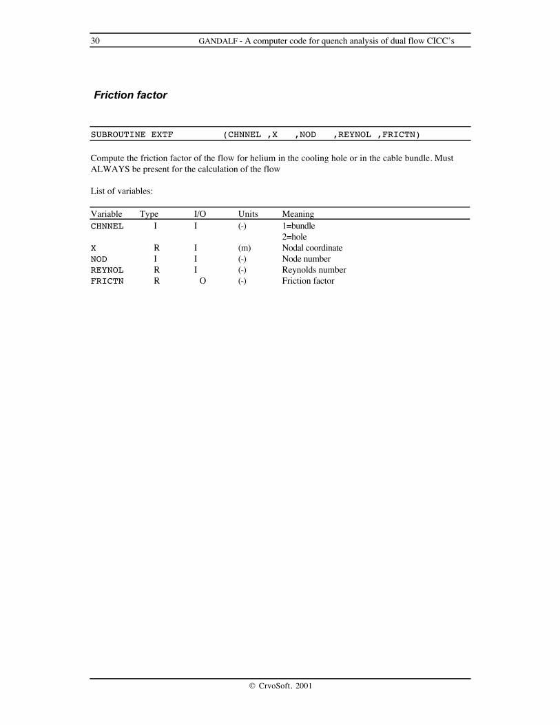
Friction factor
SUBROUTINE EXTF (CHNNEL ,X ,NOD ,REYNOL ,FRICTN)
Compute the friction factor of the flow for helium in the cooling hole or in the cable bundle. MustALWAYS be present for the calculation of the flow
List of variables:
Variable Type I/O Units MeaningCHNNEL I I (-) 1=bundle
2=holeX R I (m) Nodal coordinateNOD I I (-) Node numberREYNOL R I (-) Reynolds numberFRICTN R O (-) Friction factor

GANDALF - A computer code for quench analysis of dual flow CICC’s 31
© CryoSoft, 2001
Heat transfer coefficient
These functions define the heat transfer coefficient of the flow in the channels, and the equivalenttransfer coefficients corresponding to thermal resistances. These functions ALWAYS be present for thecalculation of the energy exchange among components.
Conductor-bundle heat transfer coefficient
SUBROUTINE EXTHCB (TIME ,X ,NOD ,T ,P ,D , TWALL ,DH ,REYNOL ,HTC_CB)
Compute the conductor-bundle helium heat transfer coefficient (in W/m2 K)
List of variables:
Variable Type I/O Units MeaningTIME R I (s) Real time in the integrationX R I (m) Nodal coordinateNOD I I (-) Node numberT R I (K) Helium temperatureP R I (Pa) Helium pressureD R I (Kg/m3) Helium densityTWALL R I (K) Wall (conductor) temperatureDH R I (m) Hydraulic diameterREYNOL R I (-) Reynolds numberHTC_CB R O (W/m2K) Conductor-bundle heat transfer coefficient
Conductor-jacket equivalent heat transfer coefficient
SUBROUTINE EXTHCJ (TIME ,X ,NOD ,TCO ,TJK , HTC_CJ)
Compute the heat transfer coefficient (in W/m2 K) equivalent to the thermal resistance between thestrands in the conductor and the jacket.
List of variables:
Variable Type I/O Units MeaningTIME R I (s) Real time in the integrationX R I (m) Nodal coordinateNOD I I (-) Node numberTCO R I (K) Helium temperature in the conductorTJK R I (K) Helium temperature in the jacketHTC_CJ R O (W/m2 K) Conductor-jacket heat transfer coefficient
32 GANDALF - A computer code for quench analysis of dual flow CICC’s
© CryoSoft, 2001
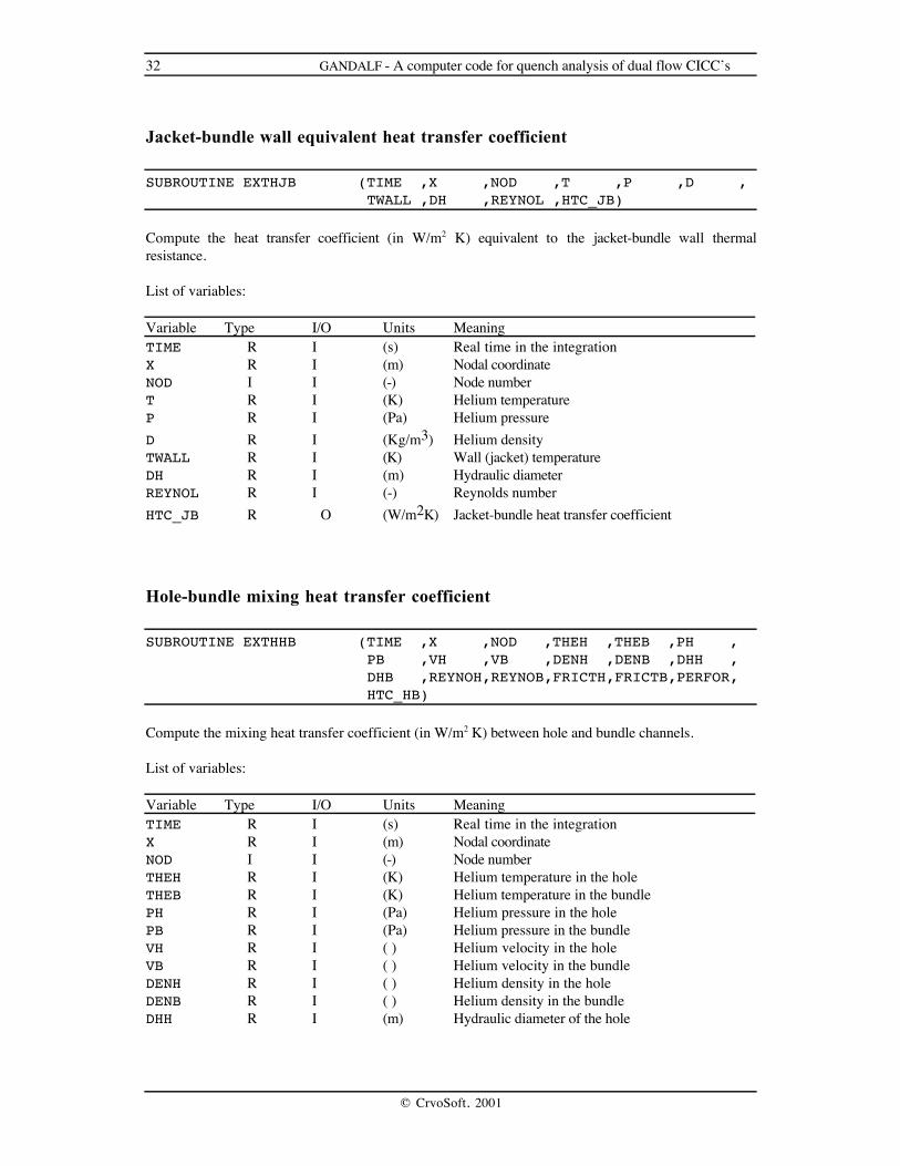
Jacket-bundle wall equivalent heat transfer coefficient
SUBROUTINE EXTHJB (TIME ,X ,NOD ,T ,P ,D , TWALL ,DH ,REYNOL ,HTC_JB)
Compute the heat transfer coefficient (in W/m2 K) equivalent to the jacket-bundle wall thermalresistance.
List of variables:
Variable Type I/O Units MeaningTIME R I (s) Real time in the integrationX R I (m) Nodal coordinateNOD I I (-) Node numberT R I (K) Helium temperatureP R I (Pa) Helium pressureD R I (Kg/m3) Helium densityTWALL R I (K) Wall (jacket) temperatureDH R I (m) Hydraulic diameterREYNOL R I (-) Reynolds numberHTC_JB R O (W/m2K) Jacket-bundle heat transfer coefficient
Hole-bundle mixing heat transfer coefficient
SUBROUTINE EXTHHB (TIME ,X ,NOD ,THEH ,THEB ,PH , PB ,VH ,VB ,DENH ,DENB ,DHH , DHB ,REYNOH,REYNOB,FRICTH,FRICTB,PERFOR, HTC_HB)
Compute the mixing heat transfer coefficient (in W/m2 K) between hole and bundle channels.
List of variables:
Variable Type I/O Units MeaningTIME R I (s) Real time in the integrationX R I (m) Nodal coordinateNOD I I (-) Node numberTHEH R I (K) Helium temperature in the holeTHEB R I (K) Helium temperature in the bundlePH R I (Pa) Helium pressure in the holePB R I (Pa) Helium pressure in the bundleVH R I ( ) Helium velocity in the holeVB R I ( ) Helium velocity in the bundleDENH R I ( ) Helium density in the holeDENB R I ( ) Helium density in the bundleDHH R I (m) Hydraulic diameter of the hole

GANDALF - A computer code for quench analysis of dual flow CICC’s 33
© CryoSoft, 2001
DHB R I (m) Hydraulic diameter of the bundleREYNOH R I (-) Reynolds number in the holeREYNOB R I (-) Reynolds number in the bundleFRICTH R I (-) Friction factor in the holeFRICTB R I (-) Friction factor in the bundlePERFOR R I (-) bundle-hole perforation (as from input)HTC_HB R O [W/m2 K] Hole-bundle heat transfer coefficient
34 GANDALF - A computer code for quench analysis of dual flow CICC’s
© CryoSoft, 2001
Quality indicators and general guidelines for running
As mentioned in the introduction, a number of quality indicators is computed by GANDALF to judgethe solution obtained. In general, a quench simulation can produce wrong results because of largediffusivity in the scheme chosen, and because the numerical approximations cause over-propagation ofthe quench front, thus triggering a non-linear process that makes the numerical solution diverge fromthe physical one. Therefore a check must be made on:
a) the amount of numerical diffusion of the scheme used, andb) the amount of numerical propagation of the fronts.
Two solution schemes are available in GANDALF. They are either a first-order accurate Euler-Backwardimplicit integrator with upwinding (METHOD=0), or a second-order accurate Crank-Nicolson implicitintegrator without upwinding (METHOD=1). The first has numerical diffusivity built in, used tostabilize the scheme, while the second has not. To clarify better the performance of the two schemes,while the first smear fronts and makes every solution smooth (sometimes unphysically), the secondtries to represent as faithfully as possible discontinuities in the solution, thus suffering fromoscillation paranoia at sharp fronts. Therefore if strong discontinuities are present in the solution (largetemperature gradients moving along the cable) a good choice is to use the first order scheme in thesesituations. The draw-back is the lower accuracy, that requires a much finer mesh and smaller steps.Thus for efficiancy and accuracy, the user should try to use the second order scheme as soon (or asoften) as possible.
The error and quality indicators computed try to quantify the considerations above. They are:
a) the maximum numerical diffusion of the scheme, andb) the estimated numerical propagation at the fronts.
While the first can be computed exactly for both schemes (and is evidently zero for the second orderscheme), for the second only an analytical approximation can be given. The two indicators above mustbe compared to the physical diffusivity and to the physical propagation speed diffusivity, checking thatthe ratio of numerical to physical quantity is smaller than 1. Again, while the first can be givenexactly, based on the material properties, the second is not known (were it known, we would be in notrouble…). A good compromise is to compare the numerical estimated propagation speed to the totalcomputed propagation speed. Note that we must require the ratio to be in this case MUCH smaller than1 (for a small numerical perturbation can result in long term physical drifts). GANDALF computes thesum of the numerical front propagations (taken in absolute terms) and the ratio of this sum to the totalpropagation speed (the time derivative of the total normal length). Note that this is different from thefront speed (typically by a factor given by the number of travelling fronts). This choice has been madebecause it is independent on the actual front position, on the number of fronts, and on their singlespeed.
Typically, an acceptable value for the ratio of numerical to total proagation speed is in the range ofsome 1 to 5 %. This ratio is the most valuable quality indicator provided. In fact, in case of adaptivemeshing, some regions of the mesh can have large elements, and thus the ratio of numerical tophysical diffusivity can be locally very large, but irrelevant to quench propagation. This last can beused to check the quality of the solution when a fixed mesh is used, as, e.g., in the analysis of coolingof a coil in pulsed mode. The acceptance limit in this case can be larger, typically up to 10 %.

GANDALF - A computer code for quench analysis of dual flow CICC’s 35
© CryoSoft, 2001
The tolerance values given above result, for a generic cable with void fraction of the order of 50 %,Copper:Non-copper ratio in the range of 2 and operating cable space current density of the order of 50A/mm2 in typical mesh sizes below 1 mm and step below 1 ms for the first order scheme, below 1 cmand below 5 ms for the second order scheme. The cryticality of the first order scheme is evident, asCPU time and memory can become a factor 5 to 10 higher.
For future development, a last, additional error indicator is computed by GANDALF. It is based on anestimate of the interpolation error of a control variable U, in this case the conductor temperature. Thesecond derivative of the control variable is computed at the nodes, and the rms interpolation error isestimated locally as:
e =1
112
2
2Dxd U
dx
where Dx is the element size (averaged at the nodes). This gives a nodal indication of the error. Themaximum error and the ratio of this maximum to the maximum of the control variable (i.e. the •-norm) are used as indications of the amount of error. Note that this error indicator cannot be used toidentify numerical front propagation and numerical diffusivity, as the higher the numerical propagationand the diffusivity of the scheme, the smoother the solution becomes. The are intended for future use inthe control of the mesh for transient problems wich do not involve quench propagation, or for areas ofthe cable far from the propagating fronts.
The error and quality indicators are output on the main listing (header of nodal results) and stored on thepost-processing file. They can be accessed for plotting or table creation through the post-processingcommands (see later). As said in the introduction, the control of the quality of the solution is left to theuser, whose responsibility is to make sure that the indicators are below tolerable levels.

36 GANDALF - A computer code for quench analysis of dual flow CICC’s
© CryoSoft, 2001
Error Codes
A limited number of checks are performed in the input phase to insure that the data set is consistent andthat the memory requirements for the solution of the problem do not exceed the availability. An errormessage is printed on the main output unit in case that one of these checks is not passed. The errormessage gives a numeric code which corresponds to the following table. Lists in braces indicateallowed values.
Code Error Meaning and corrective action
1 NNODES>MAXNOD Number of nodes exceeds the maximum allowed.Increase the MAXNOD parameter in the main code
2 NELEMS £ 0 Wrong definition of the number of elements is givenin input. Correct input.
10 ISC > 0
and
ISC ≠{31,32)
The flag for the superconductor type has a wrongvalue. Correct ISC in input
11 IST ≥ 0
and
IST ≠ {1,2}
The flag for the stabilizer type has a wrong value.Correct IST in input
12 IJK ≥ 0
and
IJK ≠ {1,2,3,11,13,14,15}
The flag for the jacket type has a wrong value. CorrectIJK in input
13 IIN ≥ 0
and
IIN ≠ {21,22,23)
The flag for the insulation type has a wrong value.Correct IIN in input
14 IOPFUN ≠ {-1,0,1} The flag for the current behaviour has a wrong value.Correct IOPFUN in input
15 IBIFUN ≠ {-1,0,1} The flag for the field behaviour has a wrong value.Correct IBIFUN in input
16 ITYMSH ≠ {-1,0,1,2,3} The flag for the mesh type has a wrong value. CorrectITYMSH in input
17 INTIAL ≠ {1,2,3,4} The flag for the initial condition has a wrong value.Correct INTIAL in input
18 IQFUN ≠ {-1,0,1} The flag for the heating input has a wrong value.Correct IQFUN in input
19 METHOD ≠ {0,1} The flag for the integration method has a wrong value.Correct METHOD in input

GANDALF - A computer code for quench analysis of dual flow CICC’s 37
© CryoSoft, 2001
Code Error Meaning and corrective action
21 ISTORP ≠ {0,1} The flag for the request of results storage has a wrongvalue. Correct ISTORP in input
23 IRESTA ≠ {0,1} The flag for restart has a wrong value. CorrectIRESTA in input
24 NELREF>NELEMS-2 The number of elements in the refined region (in casethat ITYMSH=1 or ITYMSH=3) does not allow forenough elements in the remaining of the flow path
31 XLENGT £ 0 The length of the flow path is wrongly or not given.Correct XLENGT in input
32 ASC<0 or AST<0
or
AJK<0 or AIN<0
A negative value for an area has been given in input.Correct the input value
33 ASC>0 and AST £ 0 The conductor is not stabilized. Specify a non-negativestabilizer area AST in input
34 AHEH+AHEB £ 0 No helium present in the cable. Specify a non-negativehelium area AHEB (and AHEH if required) in input
35 DHH £ 0 or DHB £ 0 Negative or zero hydraulic diameter. Specify a non-negative hydraulic diameter DHH and DHB in input
36 PHTC < 0 or PHTJ < 0 or PHTCJ< 0 or PHTHB < 0
Negative wetted perimeter. Specify a non-negativewetted perimeter PHTC or PHTJ or PHTCJ or PHTHBin input
37 NPOWER £ 0 Negative or zero exponent for electric field power law.Specify a positive exponent NPOWER in input
38 E0 £ 0 Negative or zero electric field limit for the electric fieldpower law. Specify a positive E0 in input
40 |INTIAL| = 1
and
PREINL £ 0
Negative or zero pressure at inlet. Specify a non-negative helium pressure PREINL in input
41 |INTIAL| = 1
and
PREOUT £ 0
Negative or zero pressure at outlet. Specify a non-negative helium pressure PREOUT in input
42 |INTIAL| = 1
and
TEMINL £ 0
and
PREINL ≥ PREOUT
Negative or zero temperature at inlet for an initial flowfrom inlet to outlet. Specify a non-negative heliumtemperature TEMINL in input

38 GANDALF - A computer code for quench analysis of dual flow CICC’s
© CryoSoft, 2001
Code Error Meaning and corrective action
43 |INTIAL| = 1
and
TEMOUT £ 0
and
PREINL < PREOUT
Negative or zero temperature at outlet for an initialflow from outlet to inlet. Specify a non-negativehelium temperature TEMOUT in input
44 |INTIAL| = 2
and
TEMINL £ 0 and MDTINL >=0
Negative or zero temperature at inlet. Specify a non-negative helium temperature TEMINL in input
45 |INTIAL| = 2
and
PREINL £ 0 and MDTINL >=0
Negative or zero pressure at inlet. Specify a non-negative helium pressure PREINL in input
46 |INTIAL| = 2
and
TEMOUT £ 0 and MDTINL <0
Negative or zero temperature at outlet. Specify a non-negative helium temperature TEMOUT in input
47 |INTIAL| = 2
and
PREOUT £ 0 and MDTINL <0
Negative or zero pressure at outlet. Specify a non-negative helium pressure PREOUT in input
48 |INTIAL| = 3
and
PREINL £ 0
Negative or zero pressure at inlet. Specify a non-negative helium pressure PREINL in input
49 |INTIAL| = 3
and
TEMINL £ 0
Negative or zero temperature at inlet. Specify a non-negative helium temperature TEMINL in input
50 INTIAL = 4
and
PREINI £ 0
Negative or zero initial pressure. Specify a non-negative helium pressure PREINI in input
51 INTIAL = 4
and
TEMINI £ 0
Negative or zero initial temperature. Specify a non-negative helium temperature TEMINI in input
52 PREINL £ 0 or PREOUT £ 0 Negative or zero pressure owing to a large specifiedmass flow
GANDALF - A computer code for quench analysis of dual flow CICC’s 39
© CryoSoft, 2001
Code Error Meaning and corrective action
61 End-of-file
or
Read-in error
The storage file has not been found or cannot be readduring a restart run
62 Input file does not exist
or
Read-in error
The input file has not been found or cannot be read
63 Write error
or
storage file
The storage file cannot be written
71 Matrix scaling error The system matrix is singular and cannot be scaled
72 Matrix factorization error The system matrix is singular and cannot be factorizedduring the inversion process
73 Matrix back-substitution error The system matrix is singular and cannot be back-substituted during the inversion process

40 GANDALF - A computer code for quench analysis of dual flow CICC’s
© CryoSoft, 2001
Post Processing
The post processing of the results of GANDALF is possible using the results stored on the storage. Theactual format of the storage unit can be deduced from the routines STOROP and STORER ofGANDALF (see the main code).
A dedicated program has been written for generation of plots and writing of report files (in order to havethe possibility to store and successively generate plots). The program, GANDALF_POST, is based on aPostScript™ graphic library and can generated Adobe-PostScript™ ASCII files for plotting.
The input for the program is the storage file generated by the solver GANDALF on gandalf.store, and aterminal sequence or a command file.
Outputs are generated as plots and an ASCII report (with tables of distributions and evolutions) can bewritten to g1dp.tables. In addition, two scratch files are used for read, storage and write operations.
Command language for the post processors
Here follows the list of the commands of GANDALF_POST. Note that for all keywords only the first4 characters are necessary (indicated in upper case). A ';' character in any position of a command lineindicates a comment or end-of-line (the remaining of the line is ignored). Commands can be enteredboth in upper- and lowercase.
Command Options Meaning
STOP Stop execution and close the session
LIST List the times stored on the storage unit
POST ON/OFF Switch ON or OFF (default) the writing of thepost processing ASCII tables on fileg1dp.tables
PLOT ON/OFF Switch ON (default) or OFF the PostScript™output (plots)
TABLe Start table definition. The post-processingcommands following the TABLe commandgenerate a packed table of data if POST is ON. Thetable is completed (and output) as soon as theENDTable command is found. Ignored if POST isOFF
ENDTable End table definition

GANDALF - A computer code for quench analysis of dual flow CICC’s 41
© CryoSoft, 2001
Command Options Meaning
ECHO ONOFF Turn the echo of commands ON or OFF
HISTory Plot/output the history as f(t) of:
T_COnductor conductor temperatureT_JAcket jacket temperatureT_HElium helium temperatureT_HBundle helium temperature in the bundleT_HHole helium temperature in the holePRESssure helium pressurePR_Bundle helium pressure in the bundlePR_Hole helium pressure in the holeDENSity helium densityDENBundle helium density in the bundleDENHole helium density in the holeV_Hole helium velocity in the holeV_BUndle helium velocity in the bundleVELOcity averaged helium velocityM_HOle helium mass flow in the holeM_BUndle helium mass flow in the bundleMASS_flow total helium mass flowRE_Hole helium reynolds number in the holeRE_Bundle helium reynolds number in the bundleH_CHole heat transfer coefficient conductor-holeH_CBundle heat transfer coefficient conductor-bundleH_JHole heat transfer coefficient jacket- holeH_JBundle heat transfer coefficient jacket-bundleH_CJacket heat transfer coefficient conductor-jacketH_HBundle heat transfer coefficient hole-bundleB magnetic fieldQ_EConductor external linear heat flux in the strandsQ_EJacket external linear heat flux in the jacketQ_JConductor joule heat flux in the conductorQ_JJacket joule heat flux in the jacketQ_CConductor cooling flux from the conductor to the heliumQ_CJacket cooling flux from the jacket to the heliumJ_CRitical critical currentT_CRitical critical temperatureT_CS current sharing temperatureT_MArgin temperature marginF_OPeration operating fraction of the critical current
NODE n at the node number nX x at a length x from inlet (interpolation is performed
between the closest nodes)
42 GANDALF - A computer code for quench analysis of dual flow CICC’s
© CryoSoft, 2001
Command Options Meaning
HISTory Plot/output the history of:
CURRent currentRESIstance resistanceVOLTage voltageNORMal normal zone lengthPROPagation computed instantaneous total propagation speed
(time derivative of the TOTAL normal length)P_JOule total Joule heat power in the mesh (integrated over
the length)P_EXternal total external power in the mesh (integrated over
the length)E_JOule total Joule energy deposited in the mesh (integral
in time of the Joule power)E_EXternal total external energy deposited in the mesh
(integral in time of the external power)DIFFusivity Maximum numerical diffusivityDIFRelative Maximum ratio of numerical to physical
diffusivityPNUMerical Estimated numerical total propagation speedPNURelative Ratio of numerical to computed total propagation
speedINTErpolation Estimated interpolation error on the conductor
temperatureINTRelative Estimated relative interpolation error on the
conductor temperature

GANDALF - A computer code for quench analysis of dual flow CICC’s 43
© CryoSoft, 2001
Command Options Meaning
DISTribution Plot/output the distribution as f(x) of
T_COnductor conductor temperatureT_JAcket jacket temperatureT_HElium averaged helium temperatureT_HBundle helium temperature in the bundleT_HHole helium temperature in the holePRESssure averaged helium pressurePR_Bundle helium pressure in the bundlePR_Hole helium pressure in the holeDENSity helium densityDENBundle helium density in the bundleDENHole helium density in the holeV_Hole helium velocity in the holeV_BUndle helium velocity in the bundleVELOcity averaged helium velocityM_HOle helium mass flow in the holeM_BUndle helium mass flow in the bundleMASS_flow total helium mass flowRE_Hole helium reynolds number in the holeRE_Bundle helium reynolds number in the bundleH_CHole heat transfer coefficient conductor-holeH_CBundle heat transfer coefficient conductor-bundleH_JHole heat transfer coefficient jacket- holeH_JBundle heat transfer coefficient jacket-bundleH_CJacket heat transfer coefficient conductor-jacketH_HBundle heat transfer coefficient hole-bundleB magnetic fieldQ_EConductor external linear heat flux in the strandsQ_EJacket external linear heat flux in the jacketQ_JConductor joule heat flux in the conductorQ_JJacket joule heat flux in the jacketQ_CConductor cooling flux from the conductor to the heliumQ_CJacket cooling flux from the jacket to the heliumJ_CRitical critical currentT_CRitical critical temperatureT_CS current sharing temperatureT_MArgin temperature marginF_OPeration operating fraction of the critical currentMESH_density mesh density (inverse of the element length)
TIMEs nt1,t2...tn at n times in sequence given by t1,t2,...tn (the
closest time stored is found and plotted)
The distribution curves are marked by an identifierand a legend is plotted with the recovered times

44 GANDALF - A computer code for quench analysis of dual flow CICC’s
© CryoSoft, 2001
Command Options Meaning
3_D Plot a pseudo-3D f(x,t) distribution of:
T_COnductor conductor temperatureT_JAcket jacket temperatureT_HElium averaged helium temperatureT_HBundle helium temperature in the bundleT_HHole helium temperature in the holePRESssure averaged helium pressurePR_Bundle helium pressure in the bundlePR_Hole helium pressure in the holeDENSity helium densityDENBundle helium density in the bundleDENHole helium density in the holeV_HOle helium velocity in the holeV_BUndle helium velocity in the bundleVELOcity averaged helium velocityM_HOle helium mass flow in the holeM_BUndle helium mass flow in the bundleMASS_flow total helium mass flowRE_Hole helium reynolds number in the holeRE_Bundle helium reynolds number in the bundleH_CHole heat transfer coefficient conductor-holeH_CBundle heat transfer coefficient conductor-bundleH_JHole heat transfer coefficient jacket- holeH_JBundle heat transfer coefficient jacket-bundleH_CJacket heat transfer coefficient conductor-jacketH_HBundle heat transfer coefficient hole-bundleB magnetic fieldQ_EConductor external linear heat flux in the strandsQ_EJacket external linear heat flux in the jacketQ_JConductor joule heat flux in the conductorQ_JJacket joule heat flux in the jacketQ_CConductor cooling flux from the conductor to the heliumQ_CJacket cooling flux from the jacket to the heliumJ_CRitical critical currentT_CRitical critical temperatureT_CS current sharing temperatureT_MArgin temperature marginF_OPeration operating fraction of the critical currentMESH_density mesh density (inverse of the element length)
The 3-D plot is done over the whole length and forall store times. No table output (post-processingreport) is possible as the amount of data generatedcan be considerable

GANDALF - A computer code for quench analysis of dual flow CICC’s 45
© CryoSoft, 2001
References
[1] L.Bottura, A Numerical Model for the Simulation of Quench in the ITER Magnets, Jour.Comp. Phys., 124, (1), 1996.
[2] L. Bottura, Modelling Stability in Superconducting Cables, Physica C, 310, 316-326, 1998.
Additional information on generalities of quench modelling and numerical techniques can be found in:
[3] L.Bottura, Quench Analysis of Superconducting Magnets. A Numerical Study, EC Report No.102, EUR-FU/XII/185/93, 1993
[4] L. Bottura, C. Rosso, Finite Element Simulation of Steady State and Transient ForcedConvection in Superfluid Helium, Int. J. Num. Meth. Fluids, 30, 1091-1108, 1999.

46 GANDALF - A computer code for quench analysis of dual flow CICC’s
© CryoSoft, 2001
Examples
Here are reported the input data for a sample run and restart performed with the basic GANDALF for afixed, non adaptive mesh and the input file for the post-processor GANDALF_POST. Note that theseinputs are intended as verifications, and do not necessarily satisfy the convergence requirements.
Input for the first run with GANDALF
Test Run for the manual, version 2.2 &INDATA
NELEMS= 200, XLENGT= 100.0, ITYMSH= 1, NELREF= 100, XBREFI= 40.0, XEREFI= 60,
ICHFUN= 0, AHEH = 19.6E-6, AHEB = 71.4E-6, DHH = 5.0E-3, DHB = 0.865E-3, PHTHB = 15.7E-3, PERFOR= 0.01,
ICBFUN= 0, ISC = 32, ASC = 40.6E-6, EPSLON=-0.250E-2, NPOWER= 30, E0 = 1.0E-4, IST = 1, AST = 60.8E-6, RRR = 100.0, IJK = 13, AJK = 73.5E-6, IIN = 22, AIN = 61.0E-6, PHTC = 0.330, PHTJ = 5.1E-2, PHTCJ = 0.0E+0,
INTIAL= 2, PREINL= 8.00E+5, TEMINL= 4.5, MDTINL= 5.0E-3,
IOPFUN= 0, IOP0 = 8.00E+3,
IBIFUN= 0, BISS = 10.0, BOSS = 10.0,
IQFUN = 0, Q0 = 5.00E+4, XQBEG = 45.0, XQEND = 55.0, TAUQ = 0.01000,
TEND = 500.0e-3, PSTEP = 0.1, GSTEP = 25.0E-3,
STPMIN= 1.0E-7, STPMAX= 1.0E-3,
METHOD= 0,
ISTORP= 1, IRESTA= 0, MONITR = 1,
&END

GANDALF - A computer code for quench analysis of dual flow CICC’s 47
© CryoSoft, 2001
Input for the restart with GANDALF
Test Restart for the manual, version 2.2 &INDATA
TEND = 100.0, PSTEP = 10.0, GSTEP = 1.0,
STPMIN= 1.0E-5, STPMAX= 1000.0E-3,
METHOD= 0,
ISTORP= 1, IRESTA= 1, MONITR = 1,
&END
Input for the post processor GANDALF_POST
;; post-processing commands for test run;
; distributions of some variables DIST T_CO TIME 10 .1 .2 .3 .4 .5 1 2 3 4 5 DIST T_HH TIME 10 .1 .2 .3 .4 .5 1 2 3 4 5 DIST T_HB TIME 10 .1 .2 .3 .4 .5 1 2 3 4 5 DIST PR_H TIME 10 .1 .2 .3 .4 .5 1 2 3 4 5 DIST PR_B TIME 10 .1 .2 .3 .4 .5 1 2 3 4 5 DIST VELO TIME 10 .1 .2 .3 .4 .5 1 2 3 4 5
; hystories HIST T_CO X 50 HIST PRES X 50 HIST MASS X 0 HIST MASS X 100
; pseudo 3-D plots 3_D T_CO 3_D PRES 3_D VELO
; some quality control and errors HIST PROP HIST PNUM HIST DIFF HIST DIFR
; end of the run STOP