Embed Size (px)
Citation preview

Page 1 of 37
Gamma ray attenuation in the soils of Northern Ireland, with
special reference to peat
David Beamish
British Geological Survey, Keyworth, Nottingham, NG12 5GG, UK.
Corresponding author:
David Beamish
British Geological Survey, Keyworth, Nottingham, NG12 5GG, UK
Email: [email protected]
Tel: +44(0)115 936 3432
Keywords:
Gamma‐ray; Soil; Bedrock; Airborne; Attenuation; Moisture; Peat
Beamish, D., 2013. Gamma ray attenuation in the soils of Northern Ireland, with special reference to
peat. Journal of Environmental Radioactivity, 115, 13‐27.
http://dx.doi.org/10.1016/j.jenvrad.2012.05.031
Page 2 of 37
ABSTRACT
This study considers gamma ray attenuation in relation to the soils and bedrock of Northern Ireland
using simple theory and data from a high resolution airborne survey. The bedrock is considered as a
source of radiogenic material acting as parent to the soil. Attenuation in the near‐surface is then
controlled by water content in conjunction with the porosity and density of the soil cover. The Total
Count radiometric data together with 1:250k mapping of the soils and bedrock of Northern Ireland
are used to perform statistical analyses emphasising the nature of the low count behaviour.
Estimations of the bedrock response characteristics are improved by excluding areas covered by low
count soils (organic/humic). Equally, estimations of soil response characteristics are improved by
excluding areas underlain by low count bedrock (basalt). When the spatial characteristics of the soil‐
classified data are examined in detail, the low values form spatially‐coherent zones (natural clusters)
that can potentially be interpreted as areas of increased water content for each soil type. As
predicted by theory, the highest attenuation factors are associated with the three organic soil types
studied here. Peat, in particular, is remarkably skewed to low count behaviour in its radiometric
response. Two detailed studies of blanket bogs reveal the extent to which peat may be mapped by
its radiometric response while the intra‐peat variations in the observed response may indicate areas
of thin cover together with areas of increased water content.
Page 3 of 37
1. Introduction
Airborne gamma spectrometer measurements form a significant component of the recent multi‐
parameter geophysical data sets acquired for exploration, environmental and baseline studies in the
UK (Beamish and Young, 2009). The radiometric data have been used across a range of
environmental assessments that include regional and local scale studies of natural and man‐made
distributions of excess concentrations (Lahti and Jones, 2003). The high spatial resolution data (200
m line spacing at ~56 m elevation) have also been used in a number of soil‐related studies. The
uranium (U) data are now widely applied to radon mapping (Appleton et al., 2008; Appleton et al.,
2011). The use of data from multiple surveys allowed the distribution of caesium (137Cs) across
northern Britain to be studied in detail (Scheib and Beamish, 2010). Across the soils of eastern
England, the study by Rawlins et al. (2007) indicated that the radiometric signals are useful for
making thematic maps of soil and confirmed that a large proportion of the thorium (Th) and
potassium (K) signals can be accounted for by parent material. Additionally, the airborne data (K
signal) from Northern Ireland (NI) were used to study methods for improving current estimates of
soil organic carbon (SOC) (Rawlins et al., 2009). The use of gamma ray attenuation (considered here)
in conjunction with other airborne geophysical data (conductivity) was discussed in relation to the
characterisation of wetland sites in North Wales by Beamish and Farr (2011).
Generally, environmental airborne radiometric studies employ one or more of the main, naturally
occurring radioelement estimates (K, Th and U), together with their ratios, to establish relationships
that have potential applications in areas such as soil mapping (e.g. Cook et al., 1996). Some
baseline assessments of radiometric response as a function of bedrock (parent material) and/or soil
type exist (Dickson and Scott, 1997; Beamish and White, 2011). Airborne studies differ from ground‐
based measurements in that the data are acquired uniformly and thus may encounter a range of
water bodies including the sea. The attenuation of radiometric signal due to water or soil moisture is
well‐established (Carroll, 1981) and while studies of airborne data sets may note or discard
unwanted attenuation features due to water or water‐content, extensive studies of the radiometric
signal attenuation levels in single baseline (meaning one‐off) survey data sets are rare. Repeat (time‐
lapse) airborne radiometric surveys have the capability to provide assessments of snow‐water
equivalent (SWE) and/or soil moisture by estimation of the variation in attenuation, from a known
calibrated baseline, due to varying water content (Caroll, 1987; Loijens, 1980). The ability to assess
attenuation levels from one‐off survey data is considered here. Ideally a baseline needs to be
established in order to examine both enhanced and attenuated levels of radiometric signals. Usually
the controlling factor when establishing radiometric signal levels would be that associated with the
parent material. Each rock type, with an associated geochemistry, is assumed to contain a
distribution of primordial radionuclides that were incorporated during the formation of the planet
(IAEA, 2003).
When considering the amplitude of the radiometric response observed on, or above, the surface the
simplest conceptual vertical model comprises two layers above bedrock. In the general case, the two
upper layers would be defined by soil and superficial (Quaternary) deposits whose radiogenic
content is assumed to be derived from the parent bedrock material. Whatever the near‐surface

Page 4 of 37
material (i.e. the presence/absence and thicknesses of the 2 layers) the observed response will be
derived from a given radiometric source concentration (assumed vertically uniform in the first
instance) that is primarily obtained from a shallow subsurface zone (often < 0.5 m). This zone is
largely associated with soil cover and thus it is the properties of the soil that usually govern the
radiometric decay (a standard exponential function) within a given material.
The majority of descriptions of gamma‐ray attenuation found in the literature do not specifically
include soils and soil properties. Radiometric attenuation in these materials is reviewed here and the
existing theory is recast in more familiar terms of soil density, porosity and water saturation (in the
absence of soil, other equivalent material properties will still apply). This allows two critical analyses
of generic soils (i.e. type soils) to be developed. The first relates to the main depth interval that
contributes to the observed response. The second analysis relates to the type‐behaviour of uniform
soils largely as a function of water saturation with density and porosity acting as secondary variables.
Here we use the NI survey data alongside two main 1:250,000 independent mappings of soil and
bedrock to investigate levels of response attenuation. Secondary information on response
enhancements is also obtained. Although, as part of the classification procedures, the behaviour of
individual radioelements (K, Th and U) was obtained, the most useful summary attenuation
measurement is the Total Count (TC) which, being a spectral summation, also offers enhanced
signal/noise when examining low amplitude behaviour.
The classified TC data are coupled to variations in both intrinsic bedrock radiogenic concentrations
and very‐near surface (e.g. soil) material properties. No ground control measurements of general
soil properties (particularly degree of water saturation, or soil moisture) are available at the
1:250,000 mapping scale used here. In order to extend the large‐scale geostatistical analysis to the
practical level, two case studies of attenuation behaviour across peat areas are considered. Peats, in
particular, have a high sensitivity to soil moisture content. The first study considers the largest area
of intact peat bog in Northern Ireland which is underlain by low response basalt bedrock. The second
study area contains the second largest peat bog in Northern Ireland underlain by moderately
radiogenic Carboniferous sandstones, limestones and mudstones. The case studies serve to
demonstrate the manner in which the airborne soil classified radiometric data can provide a
framework for further ground‐based studies of soil moisture.
2. Theory
2.1. Gamma ray attenuation
The interaction of gamma rays with matter and the properties of airborne gamma‐ray spectra are
discussed by Minty (1967). The shape of the gamma‐ray flux spectrum at airborne heights is a
function of the concentration and geometry of the source radioelements, the thickness of any non‐
radioactive overburden, and the height of the detector above ground.
A common approach to the modelling of gamma‐ray fields is a semi‐empirical one based on
monoenergetic (unscattered) radiation. The exponential absorption that characterises the passage
Page 5 of 37
of monochromatic electromagnetic radiation through a homogenous material is given by the Beer‐
Lambert Law (Davisson, 1965S) as:
I = I0 exp(‐µx) ... (1)
Where I0 is the initial radiation intensity. Intensity is usually described as a pulse count rate in
photon detection systems. The linear attenuation coefficient (µ) of the material is an intrinsic
property of each material and would usually be associated with a specific element of given atomic
number. The mass attenuation coefficient (µm ) of the material is given by:
µm = µ / ρ ...(2)
where ρ is density. Equation (1) may then be expressed using the mass attenuation coefficient and
the density of the material. Mass attenuation coefficients for air, water and concrete as a function of
photon energy are tabulated by Minty (1967) across the energy range from 0.01 to 3 MeV. The
attenuation coefficient is observed to decrease with increasing energy. At energies above 1 MeV, the
half‐thicknesses (thickness of material that reduces the intensity to half its initial value) range from
84 to 150 m (air), 9.8 to 17.5 cm (water) and 4.35 to 7.6 cm (concrete) (Grasty, 1979; Minty, 1967).
Løvberg (1984) discusses the general principles of gamma‐ray attenuation and the effect of moisture
content of materials. It is noted that Compton scattering (incoherent scattering) is the main
significant attenuation interaction at the energies discussed here. In such circumstances the linear
attenuation coefficient µ is proportional to the total number of electrons per unit volume of the
material. Løvberg (1984) indicates that all elements with an atomic number less than 30 will have
comparable mass attenuation coefficients. In the absence of water, soil, superficial and bedrock
materials will have comparable attenuation coefficients at a given source concentration.
Hydrogen supplied to the material as absorbed or free water (e.g. pore water) then generates an
additional attenuation provided by the additional electron content. Løvberg (1984) then establishes
expressions for the gamma ray reduction from source material containing pore water. The
expressions, discussed later, are based on the fact that water has 1.11 times as many electrons as
most materials including soils (Grasty, 1997).
2.2. Soils
Soils are characterised as a three‐phase system comprising solid, water and air. In the case of such
mixtures it is necessary to replace the attenuation (decay) coefficients (µ) in equation (1) by a
summation: i µi xiwhere i enumerates the coefficients of each material (Endrestol, 1980). Rewriting
equation (1) for a 3‐phase soil gives:
I = I0 exp ‐(µssx + µwwx + µaax) ...(3)
where is the fraction of each component and subscripts s, w and a refer to soil, water and air
respectively and s+ s +s = 1 for a unit volume.
Within the general area of soil science, a particular soil may be characterised by the volumes and/or
weights of the three materials. Total volume (V) is the sum of solid (soil) volume (Vs), water volume
Page 6 of 37
(Vw) and air volume (Va). Within this framework, porosity (ø) is defined as the volume of voids (Vw +
Va) divided by the total volume (V):
ø = (Vw + Va) / V ...(4)
The degree of saturation (S) is defined as the volume of water (Vw) divided by the volume of voids
(Vw + Va):
S = Vw / (Vw +Va) ...(5)
Both quantities are dimensionless ratios but are commonly expressed as percentages. Using these
standard definitions and by setting the total volume (V) to unity to obtain the three required
fractional contributions, we find:
s = (1‐ø) ...(6)
w = Sø ...(7)
a = ø(1‐S) ...(8)
If we consider a vertically uniform thick surface layer (a half‐space), a simple model of attenuation is
provided by substitution of equations (6), (7) and (8) into equation (3). Multiple layer models can
also be constructed by a summation procedure.
Soils are complex materials with a wide range of mineralogies giving rise to a range of atomic
numbers across the solid phase. Although the mass attenuation coefficients of some soils have been
obtained in laboratory experiments (Pires et al., 2006), the experiments tend to be carried out at
energies much lower than those considered here. In the absence of general information as a
function of soil type, we first consider representative attenuation coefficients for materials used in
previous forward simulation studies (Minty, 1967; Billings and Hovgaard, 1999). The published mass
attenuation coefficients for the potassium peak energy range (1.46 MeV) used here are 0.0528
cm2/g (soil), 0.0526 cm2/g (air) and 0.0572 cm2/g (water). Following the previous discussion on the
relative insensitivity of the solid phase mass attenuation coefficient to material type, we proceed by
retaining the stated attenuation value for all the solid phase components studied here.
The specific soils across the study area are discussed later; however, with regard to the general
assessment of soil density, it is usual to consider mineral and organic soils as two separate and
limiting categories. Mineral soils (e.g. those with no organic horizon, brown earths, podzols, gleys
and rankers) form a separate class to organic soils such as peat with an intermediate category
described as organo‐mineral soils (i.e. those with an organic horizon overlying mineral subsoil,
humic gleys, humic rankers and organic alluvium).
In recent times the increased need for assessments of soil carbon has provided increased knowledge
of soil density variations as a function of soil type particularly in the upper 50 cm. The uncertainties
in bulk density feed through to estimates of carbon stocks since they require a combined knowledge
of bulk density and soil organic carbon. Recent studies of UK soils by Bradley et al. (2005) and for
Page 7 of 37
Irish soils by Kiely et al. (2010) indicate the range of values encountered. While acknowledging that
variations with depth exist, it is possible to provide some bounding values with regard to establishing
generic soil behaviour. Most mineral soils in the UK are found to have dry bulk densities in the range
1.1 to 1.6 g/cm3 (Bradley et al., 2005). The situation with regard to humic soils, including peat, is
more complex. Bounding values of peat density in the study of Kiely et al. (2010) were 0.05 to 0.25
g.cm3 across the depth range from surface to 50 cm. A similar range of values was encountered in a
study of afforested peatlands in Ireland (Wellock et al., 2011). A standard reference vertical peat
profile is also provided by Clymo (1992) and this is used here when assigning dry bulk density values.
The reference model displays dry density values down to 0.03 g/cm3 in the uppermost layer (the
acrotelm) which then increase to 0.12 g/cm3 in the deeper catotelm layer (> 12 cm). Here we employ
a uniform value of 0.1 g/cm3 for simplicity.
2.3. Attenuation in soils
In order to specify the fractional components of a soil we use the porosity and degree of saturation
discussed above. It is then necessary to consider limiting values of these parameters for both
mineral and organic soils. In the case of mineral soils we assume some degree of water saturation in
the near‐surface material (e.g. temperate latitudes) and set water saturation at 20% in a material
with 40% porosity. Two reference ‘mineral soil’ attenuation curves are shown in Figure 1a for soils
having bulk densities of 1.1 and 1.6 g/cm3. The most rapid attenuation curve is obtained using the
higher density soil and it can be seen 90% of the observed signal (at the surface) is obtained from
the upper 40 cm. When the soil bulk density decreases to 1.1 g/cm3, the 90% threshold increases to
a depth of 60 cm. These values are in accord with many of the statements regarding the depth
contribution of gamma ray flux in the literature (e.g. Minty, 1967).
We next consider organic soils, that are distinguished by much lower bulk densities, higher porosities
and can comprise >90% water content when wet. As noted previously we employ a uniform value of
bulk density of 0.1 g/cm3 for simplicity. A peat porosity value of 80% is taken as typical for the depth
range from 0 to 100 cm following the study of Kechavarzi et al. (2010). Figure 1a shows a ‘wet peat’
attenuation curve for 80% porosity with 80% water saturation. This curve indicates that the 90%
threshold value is obtained at a depth of 60 cm. The ‘dry peat’ attenuation curve shown in Figure 1a
is obtained again using 80% porosity but with only 20% water saturation. The very low density and
low water content provide an attenuation curve that would extend the 90% threshold value to
several metres.
We also consider a uniform bedrock (i.e. no soil cover) comprising high density material. For the
potassium peak (1.46 MeV) we again use a mass attenuation coefficient of 0.0528 cm2/g noting also
that a value of 0.0522 cm2/g is given for a granite by Løvberg (1984). Using the former value and a
bulk density of 2.7 g/cm3 (e.g. a limestone), we obtain the attenuation curve shown by the dashed
line in Figure 1a with porosity and water saturation both set at 20%. Here the 90% attenuation
threshold is obtained at a very shallow depth of 20 cm due to the higher density. Finally we show the
reference attenuation curve for water (fresh water with a density of 1 g/cm3) which indicates the
extent to which the thickness of the water column will attenuate gamma ray flux.
Page 8 of 37
The type curves shown in Figure 1a illustrate the attenuation behaviour of a uniformly radioactive
half‐space and indicate the degree to which any variations in the vertical extent of near‐surface
materials may modify the attenuation behaviour.
2.4. Degree of saturation
In order to further investigate the behaviour of water content (degree of saturation) on radiometric
attenuation in soils we use the formulations discussed by Løvberg (1984) and Grasty (1997). As
noted previously, since water has 1.11 times as many electrons by weight compared to most dry
soils and rocks, water is 1.11 times more effective in attenuating gamma radiation than a typical dry
material. The relationship between the linear attenuation coefficient of a wet soil (µw) and a dry soil
(µd) is given by:
µw = µd (1+1.11w) ... (9)
where soil moisture (w) is defined as the weight of water in 1 g of dry soil (Løvberg, 1984).
The variation of the soil surface count rates with soil moisture for a uniform radioactive material is
then given by:
N1 = N2 (1+1.11w2) / (1+1.11w1) ... (10)
where N1 and N2 are the count rates at two different soil moistures w1 and w2, respectively.
As noted by Grasty (1997), the soil moisture (w) can be replaced by an expression involving porosity,
degree of saturation and dry density. Noting the previous volumetric definition of degree of
saturation (S), equation (5), we find the volume of water (Vw) can be defined by:
Vw = S e Vs ... (11)
where e is known as the void ratio and may be written in terms of porosity (ø) as:
e = Vv / Vs = ø / (1‐ ø) ... (12)
Setting Vs = 1, in equation (11) for a unit mass of solid, we obtain the required mass soil moisture
content as:
w = Vw / ρ ...(13)
where ρ is the dry bulk density. Equations (11), (12) and (13) are then used to rewrite equation (10)
to obtain the change in count rates in the same soil (of given density and porosity) due to a change
in water saturation (S).
As previously, we consider soil porosities in the range from 40% to 80% to provide an assessment of
the attenuation with degree of saturation in the context of a uniform (i.e. thick) material. Figure 1b
shows the attenuation behaviour of two reference mineral soils having bulk densities of 1.1 and 1.6
g/cm3 to a full range of saturation conditions. At full saturation, attenuation is in the range 30 to 40%
and a quasi‐linear decay behaviour is observed. There is a significant dependence on the behaviour
observed with the degree of porosity. If we take the lower density (1.1 g/cm3) mineral soil and
Page 9 of 37
increase the porosity to 60%, a much greater sensitivity to water saturation is observed (the LOW
DENSITY, HIGH POROSITY curve in Fig. 1b).
A further curve for a higher porosity mineral soil (e.g. a clay with 50% porosity) with a bulk density of
1.2 g/cm3 again shows a rapid attenuation and the reduction in count rate approaches 50% at full
saturation. The three curves serve to emphasise the strong dependence of radiometric attenuation
characteristics on the near‐surface porosity of mineral soils. Following the previous analysis we next
consider an organic soil with a bulk density of 0.1 g/cm3 and a porosity of 80% (as previously). The
sensitivity of the attenuation curve is quite distinct with a reduction in count rate of 80% at a water
saturation of only 10%. The behaviour of an intact bedrock material with bulk density of 2.7 g/cm3
(e.g. a limestone) with a porosity of 10% is shown; the curve displays the lowest sensitivity to degree
of saturation. Finally in order to demonstrate the behaviour of weathered/fractured (i.e. dual
porosity) at‐surface bedrock, the behaviour of the same material with a porosity 60% is also shown.
The attenuation curve in this case displays a slightly more rapid decay than that of the high density
mineral soil.
The type behaviour of soils (and bedrock) summarised in Figure 1 is intended to provide a
framework for the assessment of radiometric attenuation in different types of soils. It is anticipated
that soil mixtures such as organo‐mineral soils will display intermediate behaviour. Figure 1a is used
to demonstrate the principal thickness of the material contributing to the soil surface gamma ray
flux. Using a 90% contribution rule, the thicknesses range from 20 cm (limestone) to 60 cm (wet
peat). In the unusual case of dry peat, the principal thickness may extend to several metres. Wet
peat, when less than 60 cm thick, may begin to show significantly different (larger) fluxes than
thicker zones. The same is true for the other non‐organic materials but the behaviour would be
confined to smaller thickness (e.g. < 40 cm) as indicated in Figure 1a.
Given sufficiently thick materials, the attenuation of gamma rays in response to the degree of
saturation would be as shown in Figure 1b. Mineral soils, with low porosity, would potentially display
quite limited attenuation characteristics while any higher porosity materials (clays, weathered
bedrock) would provide > 40% attenuation towards higher (>70%) saturation levels. The clear
outliers in behaviour are the high porosity, low density organic soils. The attenuation response is
non‐linear and appears highly sensitive to the amount of water in the interval from zero to 20%
saturation. Beyond this interval (say > 40% saturation) the organic soils would display essentially the
same flux at all saturations. In comparative terms, the organic soils appear to be distinguishable by
their gamma ray attenuation characteristics.
3. Methodology
3.1. Airborne radiometric data
The Tellus airborne geophysical survey was conducted over a two year period (2005 and 2006) and
covered the geopolitical landmass of Northern Ireland, an area of 14,160 km2. Flight lines were
extended about 2 km, both over the coast and into the Republic of Ireland. The lines were spaced at
intervals of 200 m and orientated at 345° relative to true north, on the basis of geological trends.
The nominal flight height was 56 m, rising to 200 m over populated areas. The western portion of
the survey took place between 01 July and 05 October 2005 and the eastern survey took place
Page 10 of 37
between 29 March and 31 May 2006. An examination of meteorological data indicates that the soil
moisture regime over the period of the surveys was representative of its long term variation.
Radiometric data were acquired with an Exploranium GR820 256 channel gamma spectrometer
system comprising 32 litres of downward‐looking NaI(Tl) detectors and 8 litres of upward‐looking
detectors. Full spectrum sampling took place at 1 s intervals which equates to a distance of ~60 m
along each flight line. Standard procedures for the calibration and processing of the airborne data as
described in AGSO publications (Minty et al., 1997) and IAEA (IAEA, 1991) were carried out. Full
details of the data processing, levelling and seasonal corrections applied to the data set are given by
Beamish et al. (2006).
Uranium (238U) is measured through the radon daughter 214B in its decay chain, while thorium (232Th)
is measured through 208Tl in its decay chain. Potassium (40K) is measured directly at 1461 keV). It is
conventional to assume secular equilibrium in the decay chains of 238U and 232Th and report the
results as equivalent uranium (eU) and equivalent thorium (eTh). The standard energy windows used
are shown in Table 1.
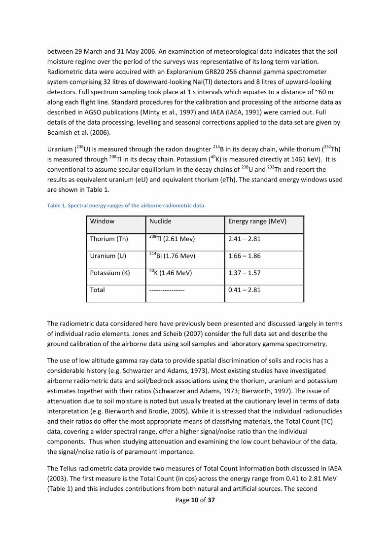
Table 1. Spectral energy ranges of the airborne radiometric data.
Window Nuclide Energy range (MeV)
Thorium (Th) 208Tl (2.61 Mev) 2.41 – 2.81
Uranium (U) 214Bi (1.76 Mev) 1.66 – 1.86
Potassium (K) 40K (1.46 MeV) 1.37 – 1.57
Total ‐‐‐‐‐‐‐‐‐‐‐‐‐‐‐‐ 0.41 – 2.81
The radiometric data considered here have previously been presented and discussed largely in terms
of individual radio elements. Jones and Scheib (2007) consider the full data set and describe the
ground calibration of the airborne data using soil samples and laboratory gamma spectrometry.
The use of low altitude gamma ray data to provide spatial discrimination of soils and rocks has a
considerable history (e.g. Schwarzer and Adams, 1973). Most existing studies have investigated
airborne radiometric data and soil/bedrock associations using the thorium, uranium and potassium
estimates together with their ratios (Schwarzer and Adams, 1973; Bierworth, 1997). The issue of
attenuation due to soil moisture is noted but usually treated at the cautionary level in terms of data
interpretation (e.g. Bierworth and Brodie, 2005). While it is stressed that the individual radionuclides
and their ratios do offer the most appropriate means of classifying materials, the Total Count (TC)
data, covering a wider spectral range, offer a higher signal/noise ratio than the individual
components. Thus when studying attenuation and examining the low count behaviour of the data,
the signal/noise ratio is of paramount importance.
The Tellus radiometric data provide two measures of Total Count information both discussed in IAEA
(2003). The first measure is the Total Count (in cps) across the energy range from 0.41 to 2.81 MeV
(Table 1) and this includes contributions from both natural and artificial sources. The second
Page 11 of 37
measure is the Total Count expressed as an air absorbed dose rate (in nGy/h). For this data set, a
linear relationship exists and the two were found to be related by TCd = 1.0 + 0.024*TC where TCd is
in nGy/h and TC is in cps. For the purposes of this study, the TC data in cps are used.
The ground area or footprint, which contributes most radioactivity to each 1 s measurement, was
assessed by Pitkin and Duval (1980) and the modelling methods used in the calculation are discussed
by Billings and Hovgaard (1999). For a stationary measurement, at a height of 60 m, 90% of the
airborne response will be provided across a circle of radius 160 to 180 m (Kock and Samuelsson,
2011). In practice, for a moving measurement, the footprint will be elliptical and the 90%
contribution area would cover 109,000 m2 (Billings and Hovgaard, 1999). Within that ellipse, the
greatest contribution will come from directly beneath the aircraft and will fall off rapidly with lateral
distance from the flight line.
This preliminary study uses soil and bedrock (e.g. soil parent material) information at a scale of
1:250,000 to obtain initial, overview information on the behaviour of radiometric attenuation
characteristics. Spatial classification of the radiometric data was undertaken using ArcGIS TM
software (Environmental Systems Research Institute, Inc., ESRI). The Tellus radiometric data,
restricted to elevations < 180 m, comprise a total of 1,337,703 data points including offshore data.
When confined to the onshore area, the data set reduces to 1,315,605 data points while still
sampling the inland water bodies. In the statistical studies that follow, the data from these areas are
excluded. Given that the airborne survey data were uniformly sampled across NI, the number of data
points obtained for each soil/bedrock classification is recorded as a proxy for the relative areal
extent of the sampling.
3.2. The soils of NI
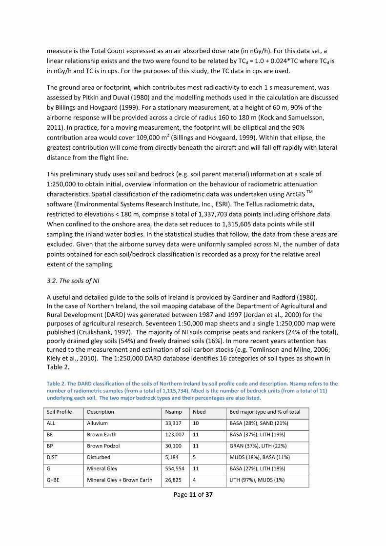
A useful and detailed guide to the soils of Ireland is provided by Gardiner and Radford (1980). In the case of Northern Ireland, the soil mapping database of the Department of Agricultural and Rural Development (DARD) was generated between 1987 and 1997 (Jordan et al., 2000) for the purposes of agricultural research. Seventeen 1:50,000 map sheets and a single 1:250,000 map were published (Cruikshank, 1997). The majority of NI soils comprise peats and rankers (24% of the total), poorly drained gley soils (54%) and freely drained soils (16%). In more recent years attention has turned to the measurement and estimation of soil carbon stocks (e.g. Tomlinson and Milne, 2006; Kiely et al., 2010). The 1:250,000 DARD database identifies 16 categories of soil types as shown in Table 2. Table 2. The DARD classification of the soils of Northern Ireland by soil profile code and description. Nsamp refers to the number of radiometric samples (from a total of 1,115,734). Nbed is the number of bedrock units (from a total of 11) underlying each soil. The two major bedrock types and their percentages are also listed.
Soil Profile Description Nsamp Nbed Bed major type and % of total
ALL Alluvium 33,317 10 BASA (28%), SAND (21%)
BE Brown Earth 123,007 11 BASA (37%), LITH (19%)
BP Brown Podzol 30,100 11 GRAN (37%), LITH (22%)
DIST Disturbed 5,184 5 MUDS (18%), BASA (11%)
G Mineral Gley 554,554 11 BASA (27%), LITH (18%)
G+BE Mineral Gley + Brown Earth 26,825 4 LITH (97%), MUDS (1%)

Page 12 of 37
G+OA Mineral Gley + Organic 1,318 1 LITH (100%)
G+R Mineral Gley + Ranker 17,858 4 LITH (97%), MUDS (0.5%)
HG Groundwater Humic Gley 55,235 11 PSAM (30%), BASA (29%)
HR Humic Ranker (<40 cm) 36,859 10 BASA (23%), PSAM (19%)
OA Organic Alluvium 2,605 6 MUDS (36%), BASA (22%)
POD Podzol 17,689 10 PSAM (41%), GRAN (20%)
PT Peat 147,145 11 PSAM (32%), BASA (25%)
R Ranker 38,796 10 LITH (29%), BASA (21%)
SR Sand Ranker 3,144 6 MUDS (51%), LITH (37%)
URB Urban 22,098 10 LITH (29%), BASA (27%)
Descriptions of the soil series are given by Gardiner and Radford (1980) and Cruikshank (1997). Table 2 identifies several types of gley soil (G, G+BE, G+OA, G+R and HG) in which drainage is impeded. The soils develop under the influence of permanent or intermittent waterlogging. The causes of drainage impedance vary and include groundwater influences (e.g. groundwater humic gley, HG). Four classes of humic or organic soils are identified as HG, HR, PT and OA. Peats, the major organic series, are characterised by a high content of organic matter (over 30%) and by being at least 30 cm in depth. Two basically different types, blanket and basin peat, occur. Water saturation in virgin peat systems may be very high (typically > 90% by volume). The podzol soils are characterised by depleted nutrients and are acidic. The brown earths are a mature and well‐drained soil. All shallow or thin soils (generally < 30 cm) are identified with the generic term ‘ranker’. Three of the soil classes (ALL, OA and PT) are also classes identified in the superficial geological data base (see later). The soil classification database excludes all water bodies and provides a radiometric sampling total of 1,115,734 data points. Three of the classifications (DIST, OA and URB) are excluded from further analysis as they are more appropriate for detailed studies. The main analysis thus takes place using the remaining 13 unit soil series classification. As indicated in Table 2 by the data sampling (Nsamp), the 5 largest soil series in the DARD classification are mineral gley (49.7%), peat (13.2%), brown earth (11%), groundwater humic gley (4.9%) and ranker (3.5%). The spatial distribution of the13 units, together with urban soils, is shown in simplified form in Figure 2a. The DARD data base includes a soil parent material (bedrock) classification except in the case of the ALL (alluvium), DIST (disturbed), OA (organic alluvium), PT (peat) and URB (urban) classes. In order to overcome the limitations of the existing parent material classification, additional geological databases were examined in relation to providing an assessment of parent material for the DARD soil data base. 3.3. Superficial deposits In addition to the bedrock classification for NI discussed later, a superficial (Quaternary) database was examined in relation to the radiometric data. The 1:250,000 geological superficial classification for NI (v 2.18, 2009) provided by the Geological Survey of Northern Ireland (GSNI) provides a 12 unit classification of superficial cover rocks. Glacial sediments (diamicton, or till) dominate the landscape

Page 13 of 37
and account for 66% of the total superficial cover. The second two most extensive units in the database are peat (with 15%) and alluvium (with 8%). These latter two units are also included in the soils classification and so an analysis of radiometric data using a superficial classification does not provide much additional information. The main analysis conducted here uses the bedrock classification described below. 3.4. Bedrock The bedrock database is a recent 1:250,000 geological bedrock classification for NI (v 2.18, 2009) provided by the GSNI. The database provides a 151 unit classification of bedrock geology when using full rock lexicon code descriptions. When a simpler lithological classification is used the number of unit descriptions reduces to 57. For practical purposes, these classifications have been further simplified. The database derived from the 1:250,000 mapping, is referred to as the simplified bedrock database. The simplified lithological classification was developed primarily for geochemical analysis (Smyth, 2007) and comprises just 11 lithological (ROCK) classifications. The simplified classifications are listed in Table 3 along with the rock type descriptions from the lexicon. Table 3 The simplified bedrock classification of Northern Ireland. Nsamp refers to the number of radiometric samples (from a total of 1,163,457). The two major soil types and their percentages, associated with each bedrock unit are also listed.
CODE BEDROCK ROCK TYPE CONSTITUENTS Nsamp Major Soils
ACID Acid Volcanics Gabbro, diorite 13799 PT (37%), G (35%)
ANDE Andesite Andesite 1742 G (76%), PT (15%)
BASA Basalt Basalt, metamorphosed basaltic rock, metamorphosed lava & tuff, interbasaltic bauxitic clay, dolerite
285194 G (52%), BE (16%)
CONG Conglomerate All conglomerates and psephite 30586 G (48%), PT (14%)
GABB Gabbro Gabbro, diorite 8599 G (33%), POD (21%)
GRAN Granite Granite, granodiorite, felsite, granite dykes, granophyre, quartz feldspar porphyry, tonalite
50705 G (26%), BP (22%)
LIME Limestone Limestone, argillaceous limestone, limestone & argillaceous rocks interbedded, mudmound reef limestone, limestone & mudstone interbedded, chalk & sandstone, dolomitic limestone
104338 G (54%), PT (8%)
LITH Lithic Arenite Lithic arenites of the Southern Uplands‐Down‐Longford Terrane (greywackes)
214812 G (46%), G+BE (12%)
MUD Mudstone All mudstone units, argillaceous layers, silty mudstone
135335 G (60%), PT (12%)
PSAM Psammite + Semipelite All psammite layers, Killeter Quartzite, metamorphosed lava & tuff (Dalradian)
159104 PT (30%), G (28%)
SAND Sandstone All sandstone units, breccia and 159243 G (54%), PT (14%)
Page 14 of 37
sandstone interbedded
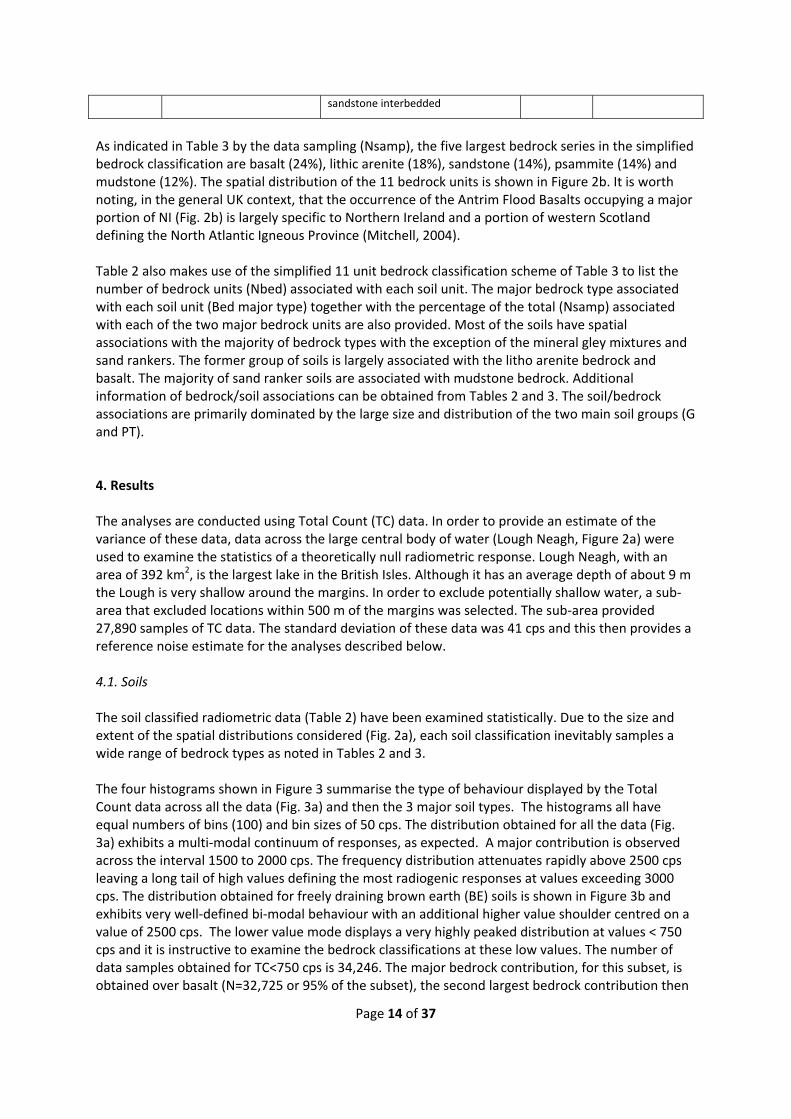
As indicated in Table 3 by the data sampling (Nsamp), the five largest bedrock series in the simplified bedrock classification are basalt (24%), lithic arenite (18%), sandstone (14%), psammite (14%) and mudstone (12%). The spatial distribution of the 11 bedrock units is shown in Figure 2b. It is worth noting, in the general UK context, that the occurrence of the Antrim Flood Basalts occupying a major portion of NI (Fig. 2b) is largely specific to Northern Ireland and a portion of western Scotland defining the North Atlantic Igneous Province (Mitchell, 2004). Table 2 also makes use of the simplified 11 unit bedrock classification scheme of Table 3 to list the number of bedrock units (Nbed) associated with each soil unit. The major bedrock type associated with each soil unit (Bed major type) together with the percentage of the total (Nsamp) associated with each of the two major bedrock units are also provided. Most of the soils have spatial associations with the majority of bedrock types with the exception of the mineral gley mixtures and sand rankers. The former group of soils is largely associated with the litho arenite bedrock and basalt. The majority of sand ranker soils are associated with mudstone bedrock. Additional information of bedrock/soil associations can be obtained from Tables 2 and 3. The soil/bedrock associations are primarily dominated by the large size and distribution of the two main soil groups (G and PT). 4. Results The analyses are conducted using Total Count (TC) data. In order to provide an estimate of the variance of these data, data across the large central body of water (Lough Neagh, Figure 2a) were used to examine the statistics of a theoretically null radiometric response. Lough Neagh, with an area of 392 km2, is the largest lake in the British Isles. Although it has an average depth of about 9 m the Lough is very shallow around the margins. In order to exclude potentially shallow water, a sub‐area that excluded locations within 500 m of the margins was selected. The sub‐area provided 27,890 samples of TC data. The standard deviation of these data was 41 cps and this then provides a reference noise estimate for the analyses described below. 4.1. Soils The soil classified radiometric data (Table 2) have been examined statistically. Due to the size and extent of the spatial distributions considered (Fig. 2a), each soil classification inevitably samples a wide range of bedrock types as noted in Tables 2 and 3. The four histograms shown in Figure 3 summarise the type of behaviour displayed by the Total Count data across all the data (Fig. 3a) and then the 3 major soil types. The histograms all have equal numbers of bins (100) and bin sizes of 50 cps. The distribution obtained for all the data (Fig. 3a) exhibits a multi‐modal continuum of responses, as expected. A major contribution is observed across the interval 1500 to 2000 cps. The frequency distribution attenuates rapidly above 2500 cps leaving a long tail of high values defining the most radiogenic responses at values exceeding 3000 cps. The distribution obtained for freely draining brown earth (BE) soils is shown in Figure 3b and exhibits very well‐defined bi‐modal behaviour with an additional higher value shoulder centred on a value of 2500 cps. The lower value mode displays a very highly peaked distribution at values < 750 cps and it is instructive to examine the bedrock classifications at these low values. The number of data samples obtained for TC<750 cps is 34,246. The major bedrock contribution, for this subset, is obtained over basalt (N=32,725 or 95% of the subset), the second largest bedrock contribution then
Page 15 of 37
comes from limestone (N=628 or 2% of the subset). It is evident that the basalt bedrock formation is a significant contributor to the low value behaviour. The large sample TC distribution for mineral gley soils is shown in Figure 3c. The distribution is again at least bi‐modal. The major peak occurs in the vicinity of 1750 cps with a relatively broad low value peak in the vicinity of 750 cps. The major bedrock contribution, for the subset with TC<750 cps, is again obtained over basalt (N=69,408 or 81% of the subset). The distribution of TC values for peat (Fig. 3d) is remarkably skewed to very low values (note the increased scale of relative frequency). The main peak in the distribution occurs between 150 and 250 cps and accounts for 25% of the total distribution. The major bedrock contributions, for the subset with TC<500 cps, are obtained over basalt (33% of the subset) and psammite (32% of the subset). The highly skewed and low value distribution obtained for peat appears to be intrinsic to this soil type, rather than derived from a bedrock (e.g. basalt) association. The distributions of the other main soil types are summarised in Figure 4. Figure 4a shows the 3 mineral gley mixed soils of the DARD classification; none exhibits the low value (TC < 750 cps) peak identified in the individual mineral gley distribution (Fig. 3c). The distributions obtained for the G+BE and G+R (not shown) pair are similar while the G+OA is characterised by a slightly lower peak value presumably associated with the organic component. The two humic soils (HG and HR) display distributions that closely resemble the highly skewed, low value distribution obtained for PT (Fig. 3d). The HR distribution additionally displays an extensive tail towards higher values. The two freely draining podsolised soil distributions (Figure 4c) show distinctly different characteristics. Brown podzol soils, associated with an absence of peat and gley in the top 50 cm, display a bi‐modal distribution. The POD distribution contains high and low (TC<750 cps) value peaks together with a shoulder peak in the vicinity of 2500 cps. Rankers are formally classified as non‐calcareous soils over non‐calcareous rock or massive limestone. Sand rankers are soils formed in non‐calcareous, unconsolidated sandy deposits other than alluvium. The two ranker distributions, shown in Fig. 4d, both display a similar higher value peak in the vicinity of 2700 cps. The sand ranker distribution shows a lower value (~1000 cps) high peak that is distinct from the lower value (~500 cps) observed in the ranker distribution. Of the distributions discussed above only the three mixed gley soils (G+BE, G+OA and G+R) and the brown podzol soil display an apparent absence of low value enhancements in the observed distributions. As can seen in Table 1 the bedrock associations of the three mixed gley soils are largely limited to one unit (LITH) while the brown podzol soil is distributed across all bedrock types but largely associated with the GRAN and LITH units. It is clearly also necessary to examine the TC behaviour of the bedrock units in conjunction with the soil information and this is now considered. 4.2. Bedrock Ideally, we would wish to examine the radiogenic properties of the bedrock parent material in the absence of soil material effects, such as attenuation. A simple first‐pass screening of the data is suggested by the analysis of the soil classified behaviour discussed above. It was demonstrated that the TC humic soil (PT, HG and HR) distributions showed highly skewed behaviour to low values with single peaks observed at TC<500 cps. A statistical appraisal was therefore carried out first using the TC data classified by bedrock and secondly by then omitting the data associated with the 3 humic soil classes. Four bedrock classified examples from the analysis are shown in Figure 5. A logarithmic abscissa is used to emphasise the low count behaviour.
Page 16 of 37
The ACID bedrock class (Fig. 5a) is originally a double peaked distribution which then reduces to more unimodal behaviour in the absence of humic soil cover. This same behaviour is repeated in the majority of TC bedrock distributions to a greater or lesser extent, as indicated in Figure 5. The original low value distribution for basalt (Fig. 5b) is simplified to apparent unimodal behaviour but still maintains central moments largely below 1000 cps. Of the 11 bedrock classifications considered, only 3 display minor change in the distributions when the humic soil classes are omitted. The 3 bedrock units displaying this behaviour are ANDE (a bimodal distribution), GRAN (unimodal) and LITH (unimodal). The first‐pass analysis of bedrock TC behaviour in the absence of the significant attenuation effects of humic soils appears to provide an improved assessment of the radiogenic properties of the bedrock classes. The analysis undertaken omitting the humic soil classes is now used to summarise the general behaviour of the bedrock classified TC data. It will be appreciated that a number of the TC frequency distributions presented above (both soils and bedrock classified) are multi‐modal, skewed and highly peaked. Such distributions do not permit simple parametric (e.g. normal or log‐normal) assessments of the central modes and variance of the data. This is a common situation when dealing with large scale regional data sets (Reimann & Filzmoser, 2000).
4.3. Summary statistics
While acknowledging the above caveat, the distributions of the bedrock classified TC data (omitting
data associated with humic soils) are summarised in the box‐whisker plot shown in Figure 6. A
logarithmic scale is used since the data span over 2 orders of magnitude and the axis has been
terminated at a value of 100 cps to exclude the extensive low value tails of most of the distributions.
The interquartile range provides an indication of the central moments of the bedrock responses.
Using Figure 5 it is possible to define 3 categories of central moments which comprise 1) TC < 1000
cps (BASA), 2) 1000<TC<2000 cps (ACID, ANDE, CONG, GABB, LIME, MUDS, PSAM and SAND) and 3)
TC>2000 cps (GRAN and LITH). While the central moments summarise average properties it is
acknowledged that it is the departures from the averages (the tails) that are of interest in more
detailed studies.
Having obtained an assessment of characteristics using a conditioned bedrock classification, it is now
possible to return to the soil classified data and consider refinements to their assessment. The box‐
whisker plot summarising the TC distributions according to soil classification is shown in Figure 7.
The data range (100 to 10,000 cps) is the same as that used in the corresponding bedrock
assessment. The box whisker soil plot summarises the full distributions (histograms) of the individual
soils shown previously (Figures 3 and 4) and it should again be noted that none conform to standard
parametric behaviour. Using Figure 7 it is possible to define 3 categories of central moments which
comprise: TC predominantly < 2000 cps (the humic soils HG, HR and PT), 750<TC<2000 cps (ALL, BE,
G, POD, R and SR) and TC predominantly >2000 cps (BP, and the gley soils G+BE, G+OA and G+R). The
latter distributions also appear to be associated with less dispersive behaviour.
The major components of the bedrock sampling, and hence parent material, involved in the soil
classification are summarised in Table 2. It can be noted that 7 of the main 13 soil units are
associated with basalt as the primary or secondary parent material. Since basalt is a relative low
value TC outlier in the bedrock assessment (Fig. 6), the soil classification TC analysis was repeated
Page 17 of 37
with the exclusion of soil locations with bedrock basalt associations. The central moment boxes (i.e.
the first and third quartiles) of this analysis are overlain as larger, outer boxes on the previous results
in Figure 6. Although a function of the number and extent of the bedrock associations, it might be
expected that the TC central moments would remain the same or move to higher values. The former
behaviour is observed in the soils BP, the 3 gley soil mixtures, POD and SR while the latter behaviour
is observed for the soils ALL, BE, G and R. The three organic soils HG, HR and PT display a consistent
movement to higher TC values.
Having established the general statistical behaviour of radiometric TC with soil type and bedrock
with special reference to their low value (attenuation) characteristics, it is instructive to examine
their behaviour in greater detail. The preceding analysis provides a context in which the low value
TC tails of each soil series can be spatially examined. A subset of the TC data for the freely draining
brown earth (BE) soils (N=123,007, Table 2) are used as an example. A 48 x 48 km area in the SW of
the survey area was selected across an area in which the relative lows (BASA) and highs (GRAN and
LITH) of the bedrock response are absent (Fig. 2b). The TC distribution for the total data set is shown
in Figure 3b. Due to the non‐parametric nature of the distribution it is not possible to employ the
usual measures of dispersion (e.g. quartiles). Figure 8 shows the location of the BE soils as polygons
and the TC values are provided as posted values for two high/low ranges. The TC data range from
132 to 2666 cps across the selected area. The low range is from 132 to 1000 cps and represents the
low value peak in the distribution (Fig. 3b). The upper range is identified by the values exceeding
2000 cps. Normally the identification of the high value outliers would be examined in further detail
using the individual radioelement values and their ratios.
In Figure 8, the low value BE data across a number of areas form spatially‐coherent zones (natural
clusters). At the southern margin of the survey (arrowed) a large BE occurrence polygon is entirely
characterised by low values. The behaviour observed indicates the integrity of the low value TC data
set. Elsewhere, low value clusters are observed within various BE polygons and these are also
arrowed. In broad terms the low value zones would be interpreted as areas of highest attenuation
and therefore the highest degree of water saturation within the BE soils.
It was anticipated that the freely draining brown earths would not show extensive areas of high
attenuation potentially related to increased water saturation and this is generally the case except in
specific areas such as that indicated in Figure 8. The intention here is not to provide a detailed
investigation of the variations of attenuation levels of the whole soil series but to indicate the
manner in which the soil classified TC data could provide a framework for further, more detailed,
studies of soil moisture content within each soil series.
4.4. Detailed studies of Peat
The humic soils, particularly peat, have a specific and high sensitivity to soil moisture content and
they account for a substantial percentage of the soils of both Northern Ireland and the Irish
Republic. In order to further demonstrate the attenuation behaviour of the TC data, two extensive
areas of peat were selected for study. In order to accommodate the established influence of bedrock
type, the first area considered abuts the coast in the NE (13 x 15 km rectangle, Figure 2) and is
underlain by basalt (Fig. 2b). The second area considered (10 x 7 km rectangle Figure 2) lies along the
political border in the SE of the area and is largely underlain by a sandstone, limestone and
Page 18 of 37
mudstone Carboniferous bedrock sequence (Fig. 2b). Both study rectangles contain protected
Ramsar wetland areas . The first area contains the Garron Plateau Ramsar site and is the largest area
of intact blanket bog in Northern Ireland. The peatland complex is described as comprising a series
of raised and flushed peat bog units, and a number of oligotrophic water bodies, all within the
enveloping blanket bog peat mantle. The second area is the Cuilcagh Mountain Ramsar site which
contains the second largest expanse of blanket bog in Northern Ireland. It is contained within a
relatively high elevation upland landscape.
The blanket bog peats of Northern Ireland are specifically discussed by EHS (2003). As far as is
known, detailed information on both the thickness of peat and its moisture content is not available
across the study areas considered. Peat depths, in blanket bog areas are described as very variable,
with an average of 0.5 to 3 m being typical. Where peat has accumulated in depressions, depths in
excess of 5 m are not unusual (EHS, 2003).
Since the underlying bedrock is distinct in the two cases, the distributions of the soil peat series were
first obtained for two relevant bedrock classes using the complete data set. The distributions of TC
for peats on basalt (N=147145) and peats not underlain by basalt (N=110,774) are shown in Figure 9.
A logarithmic scale is used to discriminate the low count behaviour and the bin size used is 25 cps. It
can be noted that both distributions display similar low value central moments. The peat on basalt
forms a very highly peaked distribution while the peat not underlain by basalt distribution is far less
peaked. The latter also displays greater dispersion to higher count values above ~400 cps. The
former distribution has a median of 229 cps with first and third quartiles of 172 and 365 cps,
respectively. The latter distribution has a median of 433 cps with first and third quartiles of 211 and
844 cps, respectively. These values form reference levels when considering the peat responses
considered below.
4.4.1. Garron Plateau
The data across this area were obtained by a series of flights between 27 April and 11 May, 2006.
The distribution of soil units across the study area is shown in Figure 10a. The plateau area is
dominated by a central NE‐SW trending axis of peat that connects to a further extensive area to the
NW. The elevations range from 0 to 549 m. In the NE a large valley descends to the coast and
contains a sequence of rankers, brown earth and alluvial soils. The valley also marks a bedrock
transition from basalt to conglomerate (Fig. 2b). The peat area is everywhere underlain by basalt.
There is a single large body of water identified at this scale, together with the seawater in the north‐
east. Provided there is a sufficient vertical column of water (e.g. >40 cm for >90% attenuation), these
bodies should provide a null (theoretically zero) radiometric response. The TC data across the area
were gridded at a 50 m cell size using a natural neighbour algorithm. The resulting image is shown
using a continuous linear colour‐scale range in Figure 10b. A high value threshold of 700 cps has
been used to preserve the dynamic range of the lower values. The maximum value across the grid
of values is 2590 cps. A few zones of negative values, associated with statistical uncertainty, are
observed over the sea. The linework of the soils distribution is also shown for reference. The highest
levels of attenuation (e.g. TC < 300 cps) are clearly observed across the zone of peat over basalt.
Outside this zone, TC values increase broadly in association with the trends and spatial variations in
soil type.
Page 19 of 37
The within‐peat variability is of interest. In the area towards the NW, significant zones of higher
value TC behaviour are observed. According to the simple theory developed previously, such zones
could arise due to the presence of drier peat (less water and hence less attenuation) or zones of
thinner peat (again less water and hence less attenuation). In order to demonstrate the highest
attenuation behaviour, the lowest value zones with TC <140 cps are identified in grey. While it is true
that these data are undoubtedly approaching the inherent noise level of the data, significant areas
of persistent low values are observed including that of the standing water body. It should be noted
that many of the remaining, much smaller bodies of standing water (not shown) have dimensions
that are likely to be small in relation to the footprint of the airborne measurement. With the
exception of a small area in the SE, all the low value TC zones occur within the area of defined peat.
The working hypothesis is that given sufficient thickness of peat across both the main Ramsar
wetland area and the peat area to the NW, the TC data are able to discriminate near‐surface zones
of enhanced water content. In addition, where enhanced peat signal levels (e.g. > 365 cps,
corresponding to the third quartile, as discussed) are observed in the NW, a thinner peat thickness
may be postulated, but reduced water content (drier zones of peat) cannot be ruled out.
4.4.2. Cuilcagh Mountain
The data across Cuilcagh Mountain were obtained by a series of flights between 06 and 20 July
2005.The study area rectangle straddles the political border (Fig. 8) and the available data
encompass only the northern slopes of the mountain. Since elevation ranges from 70 to 666 m, the
information has been assembled on an accurate DTM (Digital Terrain Model) with a 5 m cell
resolution. The images are shown in perspective view looking due south, from the north. The
distribution of soil units, draped on the DTM across the study area, is shown in Figure 10c. The area
is dominated by the blanket bog of peat that extends upslope towards the mountain ridge. The peat
boundary as identified in the DARD soil database is emphasised by a white contour. For this study, a
further potential peat boundary, obtained from the CORINE (Coordination of Information on the
Environment) land‐use 2000 database for Northern Ireland, is used. Here the land‐use code 412
(peat bogs) boundary is identified in black. There are known resolution and interpretation issues
when comparing CORINE classifications with other databases on soils (e.g. Cruickshank and
Tomlinson, 1996). The two most significant differences between the peat boundaries are identified
as A and B in Figure 10c. The first area (A) shows the CORINE peat boundary extending ~1 km west
across the Humic Ranker (HR) soil identified in the DARD database. The second area (B) of the
CORINE information defines a large non‐peat zone contouring the higher slopes. CORINE peat then
continues at higher elevations onto the ridge defined with humic ranker soils in the DARD database.
It is also apparent that there are some strong topographic associations with the soil cover
particularly in the east where gley soils (G) abut humic ranker (HR) and peat (PT) soils.
The TC data across the area were again gridded using a 50 m cell size. The resulting image is shown
using a discrete linear colour‐scale range in Figure 10d. A high value threshold of 700 cps has been
used to preserve the dynamic range of the lower values. The maximum value across the grid of
values is 3343 cps. It is apparent that the dynamic range in this area is more extensive than the
corresponding behaviour observed over the basalt (Fig. 10 b). Here the gley soil TC amplitudes
exceed 700 cps and provide strong gradients with soil boundaries in the east. Noting that the broad
Page 20 of 37
peat response is < 300 cps, it appears that the low value eastern spur of peat defined in the CORINE
map (A, Fig. 10c) matches the observed broad response for peat.
Elsewhere across the main peat area defined in both databases, there are numerous spatially
extensive, relative high amplitude responses. These responses exceed the local peat background
(e.g. 200 to 300 cps) by a factor of 2 to 3. Referring to the sensitivity of the type peat soils to
thickness (Fig. 1a) and degree of saturation (Fig.1b), then it is likely that such a response would be
associated with the most sensitive attenuation behaviour observed at low values of thickness (e.g. <
50 cm) or low values of water saturation (e.g. < 10%).
The upper slope area of peat absence identified by the CORINE database (B, Fig. 10c) is indeed
associated with increased amplitudes although they occur with considerable lateral zoning. Across
the highest slope and ridge, large amplitude responses are observed that show an association with
the mountain crest HR soils indentified in the DARD database. At lower elevations, low amplitude TC
behaviour is identified in grey/black at values < 100 cps and these zones are predominantly confined
to peat classified soils. Typically these zones would be associated with the highest degree of water
saturation.
5. Discussion and Conclusions
This study has considered the gamma ray attenuation characteristics of soil and bedrock using
simple theory and high resolution airborne radiometric data. Existing theory has been re‐examined
to allow an assessment of soil/bedrock attenuation characteristics in terms of porosity, degree of
saturation and dry bulk density. When a given material is considered as a uniformly radioactive half‐
space, the attenuation curves indicate the degree to which any vertical changes in the material
properties (e.g. soil thickness) may influence the attenuation behaviour observed. Low bulk density
organic soils form outliers to the general case in which a 90% attenuation threshold is observed at
depths of < 50 cm. Attenuation (90%) in peat soils may vary between depths of 60 cm (when wet)
and several metres (when dry). The manner in which the degree of saturation controls the
attenuation in soil/bedrock materials has been examined. The sensitivity varies between very low
(e.g. low porosity mineral soils) and very high (e.g. high porosity peat). Low porosity mineral soils
would typically provide between 30% and 40% attenuation when fully saturated while an 80%
porosity peat would provide 90% attenuation with a water saturation of just 20%. In comparative
soil terms, the high organic content soils appear to be distinguishable by their gamma ray
attenuation characteristics.
The Total Count radiometric data used in this study comprise over 1 million samples across the soils
and bedrock of Northern Ireland. The statistical distributions of the soil classified data display
distinct characteristics in their low count behaviour. Extreme highly‐skewed distributions (to low
counts) are observed in the case of organic soils with the most extreme behaviour observed in the
case of peat. The distributions of brown earths, mineral gleys and rankers exhibit multi‐modal
behaviour with a distinct low count peak.
The statistical distributions of the bedrock classified data reveal a dependence on soil type. When
the bedrock classification is repeated with the areas of humic soils omitted, the low amplitude
modes of many of the distributions are absent and the central modes of the bedrock response
Page 21 of 37
appear more peaked (better defined). Knowledge of the attenuation properties of the soils therefore
allows an improved assessment of the intrinsic radiogenic properties of the bedrock formations. In
the specific case of Northern Ireland, the extensive flood basalt distribution provides a distinctly low
value (< 1000 cps) central response when compared with the majority of bedrock formations (1000
to 2000 cps). Higher value (2000 to 3000 cps) central modes are then associated with granites and
the lithic arenites (greywackes) of the Southern Uplands‐Down‐Longford Terrane.
In an analogous manner, it is possible to reclassify the radiometric data in terms of the soil
distribution in the absence of underlying basalt. This again leads to an overall improvement in the
comparative study of soil radiometric response characteristics. Within this revised soil framework,
the low value peat response is quite distinct while the two other organic soils studied here, although
displaying low value central moments, provide overlap with a number of other soil responses. Using
the freely‐draining brown earth soils as an example, the spatial integrity of the low value data set
was demonstrated. The low values form spatially‐coherent zones (natural clusters) that can
potentially be interpreted as areas of increased water content for each soil type.
The degree to which areas covered by peat can be distinguished by the radiometric data was
examined in more detail in two studies of extensive blanket bogs. The attenuation levels associated
with existing database peat boundaries show broad agreement together with a number of quite
distinct differences. Strong intra‐peat response variations are also apparent. According to theory,
the large response variations observed may be due to variations in thickness and/or water content.
It can be postulated that the higher amplitude intra‐peat zones may be due to areas with thin peat
cover while the areas with the lowest amplitudes coincide with the highest water content. A fuller
understanding of the detailed behaviour observed will require appropriate ground investigations to
calibrate the radiometric information.
Acknowledgements
My thanks go to the two referees whose contributions helped improve the manuscript. The data
used in the study come from the Tellus Project which was funded by DETI and by the Building
Sustainable Prosperity scheme of the Rural Development Programme (Department of Agriculture
and Rural Development of Northern Ireland). This paper is published with the permission of the
Executive Director, British Geological Survey (NERC).
References
Appleton, J.D., Miles, J.C.H., Green, B.M.R., Larmour, R., 2008. Pilot study of the application of
Tellus airborne radiometric and soil geochemical data for radon mapping. Journal of Environmental
Radioactivity 99, 1687‐1697.
Page 22 of 37
Appleton, J.D., Miles, J.C.H., Young., M., 2011. Comparison of Northern Ireland radon maps based on
indoor radon measurements and geology with maps derived by predictive modelling of airborne
radiometric and ground permeability data. Science of the Total Environment 409, 1572–1583.
Beamish, D., Cuss, R.J., Lahti, M., 2006. The Tellus airborne geophysical survey of northern Ireland:
final processing report. British Geological Survey Internal Report, IR/06/136.
Beamish, D., Young. M., 2009. Geophysics of Northern Ireland: the Tellus effect. First Break 27, 43‐
49.
Beamish, D., Farr, G., 2011. Airborne geophysical data used to characterise groundwater dependant
wetlands. Near Surface 2011 – 17th European Meeting of Environmental and Engineering
Geophysics, Leicester, UK, 12 ‐ 14 September 2011, Extended Abstract.
Beamish, D., White, J.C., 2011. A radiometric airborne geophysical survey of the Isle of Wight,
Proceedings of the Geologists’ Association, 122, 787‐799.
Bierwirth, P.N., 1997. The use of airborne gamma‐emission data for detecting soil properties.
Proceedings of the Third International Airborne Remote Sensing Conference and Exhibition,
Copenhagen, Denmark.
Bierwirth, P.N., Brodie, R.S., 2005, Identifying acid sulfate soil hotspots from airborne gamma
radiometric data & GIS analysis. BRS Report, ISBN 0642475539.
Billings, S., Hovgaard, J., 1999. Modelling detector response in airborne gamma‐ray spectrometry.
Geophysics 64, 1378‐1392.
Bradley, R.I., Milne, R., Bell, J., Lilley, A., Jordan, C., Higgins, A., 2005. A soil carbon and land use
database for the United Kingdom. Soil Use and Management 21, 363‐369.
Carroll, T.R., 1981. Airborne soil moisture measurement using natural terrestrial gamma radiation.
Soil Science 132, 358‐366.
Carroll, T.R., 1987. Operational airborne measurements of snow water equivalent and soil moisture
using terrestrial gamma radiation in the United States. Large Scale Effects of Seasonal Snow Cover
(Proceedings of the Vancouver Symposium, August 1987). IAHS Publ. no. 166.
Cruickshank, M.M., Tomlinson, R.W., 1996. Application of CORINE land cover methodology to the UK
‐ some issues raised from northern Ireland. Global Ecology and Biogeography Letters 5, 235‐248.
Cruickshank, J.G., 1997. Soil and environment: Northern Ireland. Agricultural and Environment
Science Division, DANI and The Agricultural Environmental Science Department, The Queens
University of Belfast, 214pp.
Clymo, R. S., 1992. Models of peat growth. Suo 43, 127–136.
Cook, S. E., Corner, R.J., Groves, P.R. and Grealish, G.J., 1996. Use of airborne gamma‐radiometric
data for soil mapping. Australian Journal of Soil Research 34, 183–194.

Page 23 of 37
Davisson, C.M., 1965. Gamma‐ray attenuation coefficients. In: Siegbahn (Ed.), Alpha‐, Beta‐ and
Gamma‐ray Spectroscopy, Vol. 1, North Holland, Amsterdam, pp. 827‐843.
Dickson, B.L. and Scott, K.M., 1997. Interpretation of aerial gamma‐ray surveys – adding the
geochemical factors. AGSO Journal of Australian Geology and Geophysics 17, 187‐200.
Endrestol, G., 1980. Principle and method for measurement of snow water equivalent by detection
of natural gamma radiation. Hydrogeological Sciences, Bulletin‐des Sciences Hydrologiques 25, 77‐
83.
Environment & Heritage Service (EHS), 2003. Northern Ireland Habitat Action Plan: Blanket Bog, 1‐
24.
Gardiner, M.J., Radford, T., 1980. Soil Associations of Ireland and their Land Use Potential:
Explanatory Bulletin to Soil Map of Ireland 1980. Soil Survey Bulletin No. 36. An Foras Talúntais,
Dublin, Ireland.
Grasty, R.L., 1997. Radon emanation and soil moisture effects on airborne gamma ray
measurements. Geophysics 62, 1379‐1385.
Grasty, R. L., 1979. Gamma‐ray spectrometric methods in uranium exploration, 2, Theory and
operational procedures. In: Hood, P.J., (Ed.), Geophysics and Geochemistry in the Search for Metallic
Ores, Proceedings of Exploration'77 Symposium, Geological Survey of Canada Economic Geology
Report 31, Ottawa, pp. 147‐161.
IAEA, 1991. Airborne gamma ray spectrometer surveying. International Atomic Energy Agency,
Vienna, Technical Report Series, No. 323.
IAEA, 2003. Guidelines for radioelement mapping using gamma ray spectrometry, International
Atomic Energy Agency, Vienna, Technical Report Series, No. 136.
Jones, D.J., Scheib, C., 2007. A preliminary interpretation of Tellus airborne radiometric data. British
Geological Survey Commissioned Report, CR/07/061.
Jordan, C., Higgins, A., Hamill, K., Cruickshank, J.G., 2000. The Soil Geochemical Atlas of Northern
Ireland. Department of Agriculture and Rural Development, Northern Ireland.
Kechavarzi, C., Dawson, Q., Leeds‐Harrison, P.B., 2010. Physical properties of low‐lying agricultural
peat soils in England. Geoderma 154, 196–202
Kiely, G., McGoff, N., Eaton, J., Leahy, P., Xu, X., Carton, O., 2010. SoilC – Measuring and Modelling of
Soil Carbon Stocks and Stock Changes in Irish Soils. EPA report Strive No. 35. EPA, Dublin, Ireland.
ISBN: 978‐1‐84995‐320‐6.
Kock, P., Samuelsson, C., 2011. Comparison of airborne and terrestrial gamma spectrometry
measurements ‐ evaluation of three areas in southern Sweden. Journal of Environmental
Radioactivity 102, 605‐613.
Page 24 of 37
Lahti, M., Jones, D.G., 2003. Environmental applications of airborne radiometric surveys. First Break
21, 35‐41.
Loijens, H.S., 1980. Determination of soil water content from terrestrial gamma radiation. Water
Resources Research 16, 565‐573.
Løvborg, L., 1984. The calibration of portable and airborne gamma‐ray spectrometers ‐ theory,
problems and facilities. Risø Report M‐2456, pp. 207.
Minty, B.R.S., 1967. Fundamentals of airborne gamma‐ray spectrometry. AGSO Journal of Australian
Geology and Geophysics 17, 39‐50.
Minty, B.R.S., Luyendyk, A.P.J., Brodie, R.C., 1997. Calibration and data processing for airborne
gamma‐ray spectrometry. AGSO Journal of Australian Geology and Geophysics 17, 51‐62.
Mitchell W.I. (ed.) 2004. The geology of Northern Ireland: Our Natural Foundation. Geological Survey
of Northern Ireland, Belfast. ISBN 0852724543.Pires, L.F., Bacchi, O.S., Dias, N.M.P., 2006. Gamma‐
ray beam attenuation to assess the influence of soil texture on structure deformation. Nukleonika
51, 125−129.
Pitkin, J. A., Duval, J. S., 1980. Design parameters for aerial gamma ray surveys. Geophysics 45,
1427–1439.
Rawlins, B.G., Webster, R., Lark, R.M., 2007. Understanding airborne radiometric survey signals
across part of eastern England. Earth Surface Processes and Landforms 32, 1503‐1515.
Rawlins, B.G., Marchant, B.P, Smyth, D., Scheib, C., Lark, R.M., Jordan, C., 2009. Airborne radiometric
survey data and a DTM as covariates for regional scale mapping of soil organic carbon across
Northern Ireland. European Journal of Soil Science 60, 44–54.
Reimann, C., Filzmoser, P., 2000. Normal and lognormal data distribution in geochemistry: death of a
myth. Consequences for the statistical treatment of geochemical and environmental data
Environmental Geology 39, 1001‐1014.
Schwarzer, T.G., Adams, J.A.S., 1973. Rock and Soil Discrimination by Low Altitude Airborne Gamma‐
Ray spectrometry in Payne County, Oklahoma. Economic Geology 68, 1297‐1312.
Scheib C, Beamish D., 2010. High spatial resolution observations of 137Cs in northern Britain and
Ireland from airborne geophysical survey. Journal of Environmental Radioactivity 101, 670‐680.
Smyth, D., 2007. Methods used in the Tellus Geochemical Mapping of Northern Ireland. British
Geological Survey Open Report, OR/07/022.
Tomlinson, R.W., Milne, R.M., 2006. Soil carbon stocks and land cover in Northern Ireland from 1939
to 2000. Applied Geography 26, 18‐39.
Wellock, M., Reidy, B., Laperle, C.M., Bolger, T., Kiely, G., 2011. Soil organic carbon stocks of
afforested peatlands in Ireland. Forestry 84, 441‐451.
Page 25 of 37
Figure Captions
Figure 1. Theoretical attenuation behaviour of soil/bedrock types. The parameters defining the soil
types are discussed in the text. (a) Variation with thickness assuming a uniform half‐space. A 90%
attenuation level is shown by the horizontal dash line. (b) Variation with degree of saturation (soil
moisture or moisture content).
Figure 2. Soil and bedrock maps of Northern Ireland. Three rectangles outline 3 detailed study areas
discussed in the text. (a) Soil distribution according to DARD database using a 13‐unit (+Urban) soil
classification. (b) Simplified 11‐unit bedrock classification.
Figure 3. Normalised distributions of the Total Count data for all the data and the 3 major soil types.
(a) All data, (b) brown earth (BE), (c) mineral gley (G) and (d) peat (PT). The number of samples (N) is
shown for each case.
Figure 4. Normalised distributions of the Total Count data for 8 soil types. (a) mineral gley+brown
earth (G+BE) and mineral gley+organic (G+OA), (b) groundwater humic gley (HG) and humic ranker
(HR), (c) brown podzol (BP) and podzol (POD) and (d) ranker (R) and sand ranker.
Figure 5. Normalised distributions of the Total Count data (logarithmic scale) for the 4 major bedrock
classes, with and without humic soil cover. (a) acid volcanic (ACID), (b) basalt (BASA), (c) psammite
(PSAM) and (d) sandstone (SAND).
Figure 6. Box and whisker plot summarising the statistical behaviour of the Total Count data
(logarithmic scale) classified according to simplified bedrock, and with overlying organic/humic soils
omitted. The infilled box indicates the first and third quartiles of each distribution with the
enclosed horizontal bar denoting the median value. The terminating bars at the end of each vertical
line denote the range of the data. Outliers are omitted. ACID=acid volcanics, ANDE=andesite,
BASA=basalt, CONG=conglomerate, GABB=gabbro, GRAN=granite, LIME=limestone, LITH=lithic
arenite, MUD=mudstone, PSAM= psammite + semipelite, SAND=sandstone.
Figure 7. Box and whisker plot summarising the statistical behaviour of the Total Count data
(logarithmic scale) classified according to soil type. The larger (open) rectangles indicate the central
moments (i.e. first and third quartiles) of the distributions when samples with underlying Basalt
bedrock are omitted. ALL= alluvium, BE=brown earth, BP=brown podzol, G=mineral gley,
Page 26 of 37
G+BE=mineral gley + brown earth, G+OA=mineral gley + organic, G+R=mineral gley + ranker,
HG=groundwater humic gley, POD=podzol, PT=peat, R=ranker, SR=sand ranker.
Figure 8. Brown Earth soil distribution (polygons) in the SW of the survey area within a 48 x 48 km
rectangle. The southern‐most line is the border. The values of the Total Count data are shown using
two ranges. The low range is from 132 to 1000 cps and the high range is from 2000 to 2666 cps.
Areas in which natural clusters of low value counts are observed are highlighted with arrows. Two
infill areas indicate (i) the town of Enniskillen and (ii) the Cuilcagh Mountain Ramsar site discussed in
the text.
Figure 9. Normalised distributions of the Total Count data (logarithmic scale) for peat on basalt
bedrock and peat with no underlying basalt bedrock.
Figure 10. Detailed studies of Total Count data across major blanket bog (Peat) areas. (a) Soil and
water distribution across 13 x 15 km Garron Plateau area. (b) Total Count (TC) distribution across
Garron Plateau area with soil distribution overlaid as lines. The lowest value TC data (< 140 cps) are
shown in grey. (c) Soil (DARD) distribution across the 10 x 7 km Cuilcagh Mountain area. The data are
shown overlaid on an accurate DTM looking due South. The heavy white contour line denotes the
DARD classified Peat boundary and the heavy black contour denotes the CORINE classified Peat
boundary. An area of no Peat within the DARD database is denoted by ‘A’ and a no Peat area within
the CORINE database is denoted by ‘B’. (d) Total Count (TC) distribution across Cuilcagh Mountain
area with Peat boundaries identified with white (DARD) and black (CORINE) heavy contours.

Page 27 of 37
Figure 1 Theoretical attenuation behaviour of soil/bedrock types. The parameters defining the soil
types are discussed in the text. (a) Variation with thickness assuming a uniform half‐space. A 90%
attenuation level is shown by the horizontal dash line. (b) Variation with degree of saturation (soil
moisture or moisture content).

Page 28 of 37
Figure 2 Soil and bedrock maps of Northern Ireland. Three rectangles outline 3 detailed study areas
discussed in the text. (a) Soil distribution according to DARD database using a 13‐unit (+Urban) soil
classification. (b) Simplified 11‐unit bedrock classification.

Page 29 of 37
Figure 3 Normalised distributions of the Total Count data for all the data and the 3 major soil types.
(a) All data, (b) brown earth (BE), (c) mineral gley (G) and (d) peat (PT). The number of samples (N) is
shown for each case.
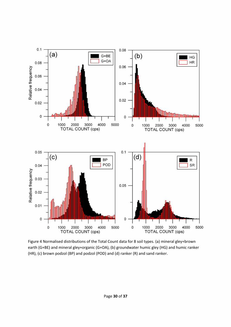
Page 30 of 37
Figure 4 Normalised distributions of the Total Count data for 8 soil types. (a) mineral gley+brown
earth (G+BE) and mineral gley+organic (G+OA), (b) groundwater humic gley (HG) and humic ranker
(HR), (c) brown podzol (BP) and podzol (POD) and (d) ranker (R) and sand ranker.
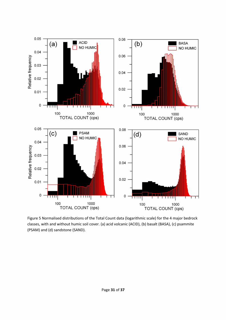
Page 31 of 37
Figure 5 Normalised distributions of the Total Count data (logarithmic scale) for the 4 major bedrock
classes, with and without humic soil cover. (a) acid volcanic (ACID), (b) basalt (BASA), (c) psammite
(PSAM) and (d) sandstone (SAND).
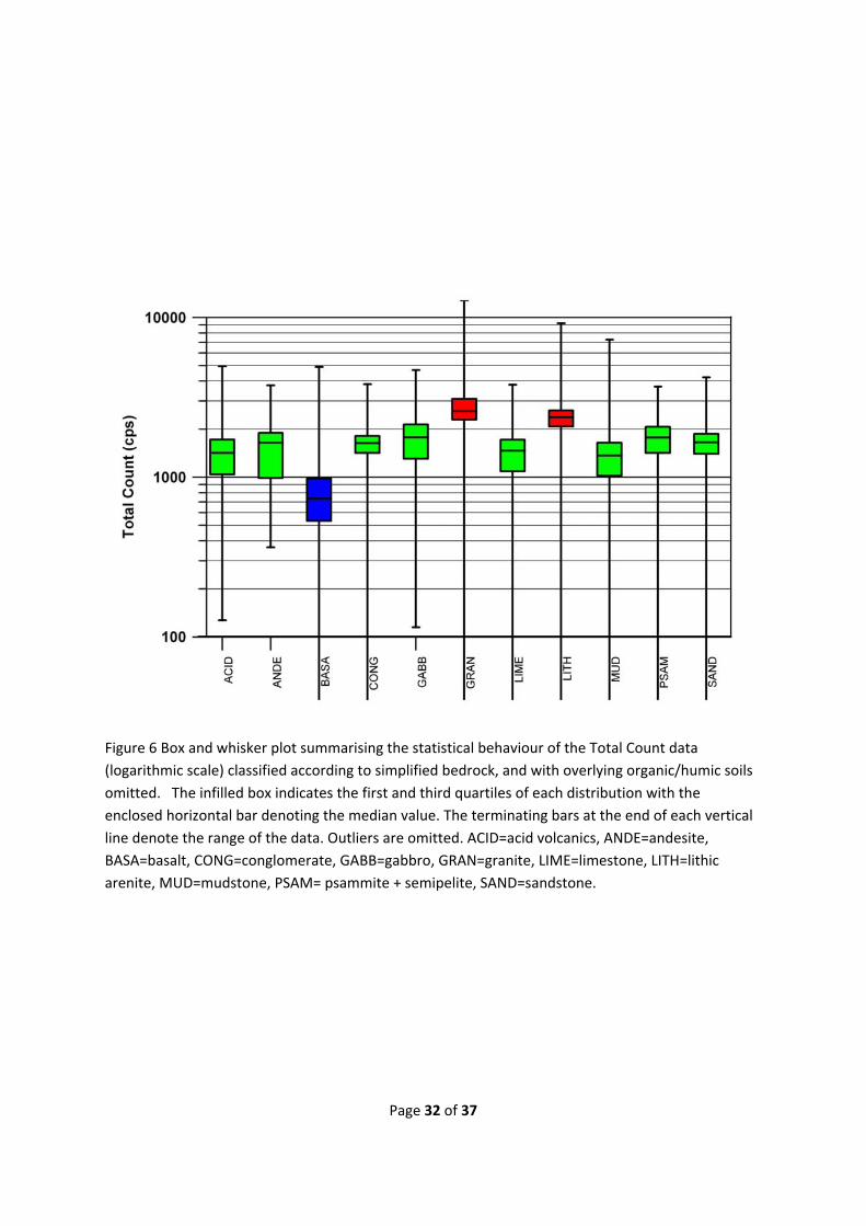
Page 32 of 37
Figure 6 Box and whisker plot summarising the statistical behaviour of the Total Count data
(logarithmic scale) classified according to simplified bedrock, and with overlying organic/humic soils
omitted. The infilled box indicates the first and third quartiles of each distribution with the
enclosed horizontal bar denoting the median value. The terminating bars at the end of each vertical
line denote the range of the data. Outliers are omitted. ACID=acid volcanics, ANDE=andesite,
BASA=basalt, CONG=conglomerate, GABB=gabbro, GRAN=granite, LIME=limestone, LITH=lithic
arenite, MUD=mudstone, PSAM= psammite + semipelite, SAND=sandstone.

Page 33 of 37
Figure 7 Box and whisker plot summarising the statistical behaviour of the Total Count data
(logarithmic scale) classified according to soil type. The larger (open) rectangles indicate the central
moments (i.e. first and third quartiles) of the distributions when samples with underlying Basalt
bedrock are omitted. ALL= alluvium, BE=brown earth, BP=brown podzol, G=mineral gley,
G+BE=mineral gley + brown earth, G+OA=mineral gley + organic, G+R=mineral gley + ranker,
HG=groundwater humic gley, POD=podzol, PT=peat, R=ranker, SR=sand ranker.
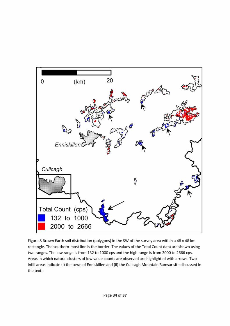
Page 34 of 37
Figure 8 Brown Earth soil distribution (polygons) in the SW of the survey area within a 48 x 48 km
rectangle. The southern‐most line is the border. The values of the Total Count data are shown using
two ranges. The low range is from 132 to 1000 cps and the high range is from 2000 to 2666 cps.
Areas in which natural clusters of low value counts are observed are highlighted with arrows. Two
infill areas indicate (i) the town of Enniskillen and (ii) the Cuilcagh Mountain Ramsar site discussed in
the text.
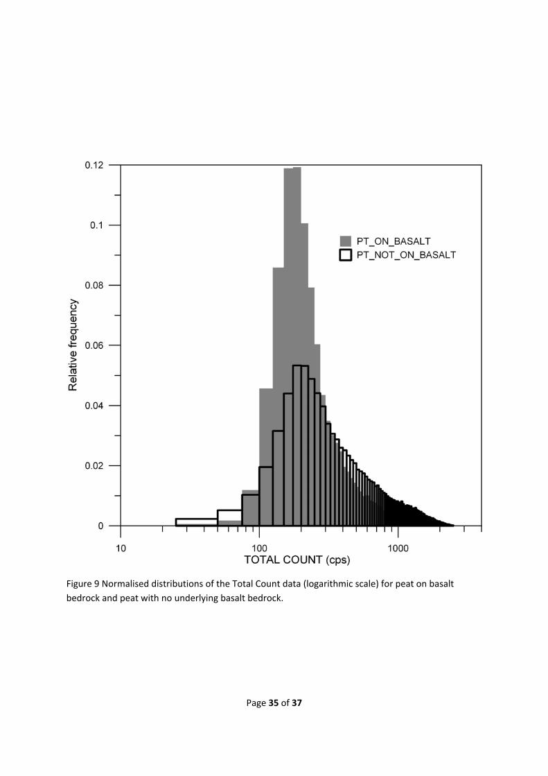
Page 35 of 37
Figure 9 Normalised distributions of the Total Count data (logarithmic scale) for peat on basalt
bedrock and peat with no underlying basalt bedrock.

Page 36 of 37
Figure 10 Detailed studies of Total Count data across major blanket bog (Peat) areas. (a) Soil and
water distribution across 13 x 15 km Garron Plateau area. (b) Total Count (TC) distribution across
Garron Plateau area with soil distribution overlaid as lines. The lowest value TC data (< 140 cps) are
shown in grey. (c) Soil (DARD) distribution across the 10 x 7 km Cuilcagh Mountain area. The data are
shown overlaid on an accurate DTM looking due South. The heavy white contour line denotes the
DARD classified Peat boundary and the heavy black contour denotes the CORINE classified Peat
boundary. An area of no Peat within the DARD database is denoted by ‘A’ and a no Peat area within
the CORINE database is denoted by ‘B’. (d) Total Count (TC) distribution across Cuilcagh Mountain
area with Peat boundaries identified with white (DARD) and black (CORINE) heavy contours.
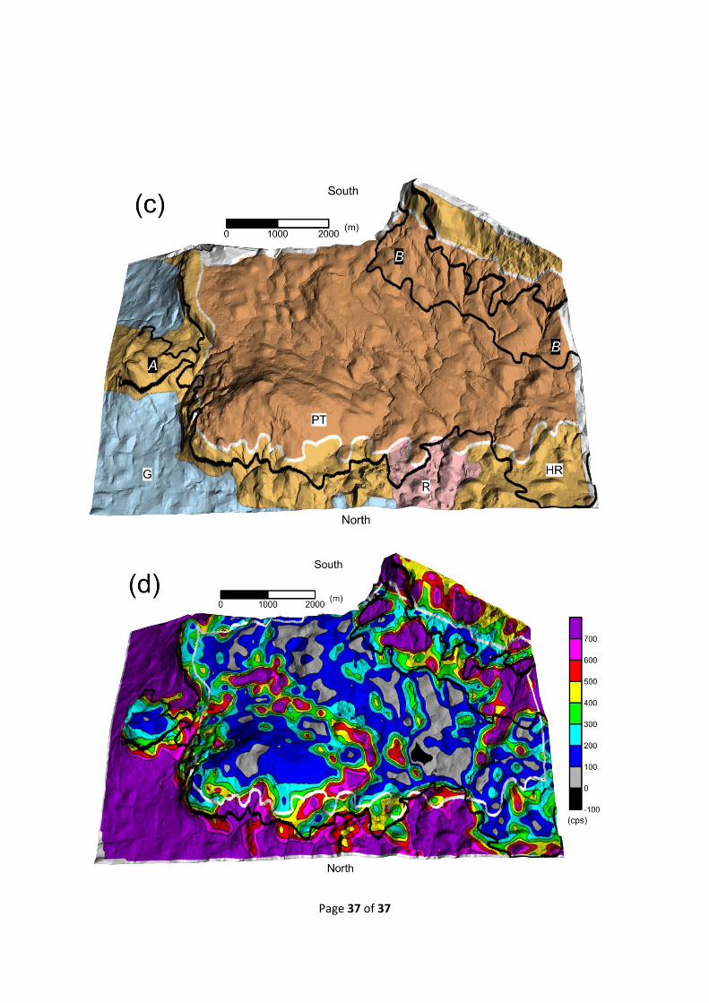
Page 37 of 37