Embed Size (px)
Citation preview
Loughborough UniversityInstitutional Repository
Disturbance/uncertaintyestimation and attenuation
techniques in PMSMdrives�a survey
This item was submitted to Loughborough University's Institutional Repositoryby the/an author.
Citation: YANG, J. ...et al., 2016. Disturbance/uncertainty estimation andattenuation techniques in PMSM drives�a survey. IEEE Transactions on In-dustrial Electronics, 64(4), pp. 3273-3285.
Additional Information:
• Personal use of this material is permitted. Permission from IEEE mustbe obtained for all other uses, in any current or future media, includingreprinting/republishing this material for advertising or promotional pur-poses, creating new collective works, for resale or redistribution to serversor lists, or reuse of any copyrighted component of this work in other works.
Metadata Record: https://dspace.lboro.ac.uk/2134/24394
Version: Accepted for publication
Publisher: c© IEEE
Rights: This work is made available according to the conditions of the Cre-ative Commons Attribution-NonCommercial-NoDerivatives 4.0 International(CC BY-NC-ND 4.0) licence. Full details of this licence are available at:https://creativecommons.org/licenses/by-nc-nd/4.0/
Please cite the published version.
IEEE TRANSACTIONS ON INDUSTRIAL ELECTRONICS 1
Disturbance/Uncertainty Estimation and AttenuationTechniques in PMSM Drives–A Survey
Jun Yang, Member, IEEE, Wen-Hua Chen, Senior Member, IEEE, Shihua Li, Senior Member, IEEE,Lei Guo and Yunda Yan, Student Member, IEEE
Abstract—This paper gives a comprehensive overview ondisturbance/uncertainty estimation and attenuation (DUEA) tech-niques in permanent magnet synchronous motor (PMSM) drives.Various disturbances and uncertainties in PMSM and also otheralternating current (AC) motor drives are first reviewed whichshows they have different behaviors and appear in differentcontrol loops of the system. The existing DUEA and other relevantcontrol methods in handling disturbances and uncertaintieswidely used in PMSM drives, and their latest developments arethen discussed and summarized. It also provides in-depth analysisof the relationship between these advanced control methods inthe context of PMSM systems. When dealing with uncertainties,it is shown that DUEA has a different but complementarymechanism to widely used robust control and adaptive control.The similarities and differences in disturbance attenuation ofDUEA and other promising methods such as internal modelcontrol and output regulation theory have been analyzed indetail. The wide applications of these methods in different ACmotor drives (in particular in PMSM drives) are categorized andsummarized. Finally the paper ends with the discussion on futuredirections in this area.
Index Terms—Disturbances, uncertainties, PMSM drives, esti-mation, robustness, robust control, adaptive control.
I. INTRODUCTION
W ITH the increasing demands of higher precision ma-chine drives, AC machine drives, which are widely
considered as a substitute of direct current (DC) machinedrives, are deemed as the most prevailing components of mod-ern motion control systems due to many distinctive featuresthey offer. Among various AC machine drives, PMSM hasbeen receiving abundant attention because of its advantageousfeatures including high efficiency, high power density, largetorque-to-inertia ratio, low noise, and free maintenance [1]–[5]. As such, PMSM drives have been extensively applied to
Manuscript received October 9, 2015; revised January 11, 2016, February21, 2016, April 11, 2016 and May 03, 2016; accepted May 17, 2016.
Copyright (c) 2015 IEEE. Personal use of this material is permitted.However, permission to use this material for any other purposes must beobtained from the IEEE by sending a request to [email protected].
This work was supported in part by National Natural Science Foundationof China under Grants, 61203011, 61473080 and 61573099, PhD ProgramFoundation of Ministry of Education of China under Grant 20120092120031,Natural Science Foundation of Jiangsu Province under Grant BK2012327,China Postdoctoral Science Foundation under Grants 2013M540406 and2014T70455, and a research grant from the Australian Research Council.
J. Yang, S. Li and Y. Yan are with School of Automation, Southeast Univer-sity, Nanjing 210096, China (e-mails: [email protected], [email protected] [email protected]).
W.-H. Chen is with the Department of Aeronautical and AutomotiveEngineering, Loughborough University, Leicestershire, LE11 3TU, UK (e-mail: [email protected]).
L. Guo is with the School of Electrical Engineering and Automation,Beihang University, Beijing, China (e-mail: [email protected]).
a variety of industrial sectors, such as robotics, machine tools,electrical vehicles, power generations and aerospace [4].
Despite many advantages described above, high precisioncontrol of PMSM drives is rather challenging because themotion dynamics of PMSM are complicated and intrinsicallynonlinear, and, in addition, subject to various sources of distur-bances and uncertainties [6]–[10]. Aiming to achieve desiredservo control performance, apart from classical proportional-integral-derivative (PID) controllers, plenty of advanced con-trol algorithms have been put forward for AC machine drives,for example, model predictive control [5], [11], [12], robustand adaptive control [13]–[19], internal model control [20],output regulation [2], [21], disturbance observer-based control(DOBC) [4], [5], [22]–[32] and active disturbance rejectioncontrol (ADRC) [12], [33]–[36], to name but a few.
It has been widely recognized that a crucial task of con-troller design for PMSM systems is to reject various externaldisturbances and improve robustness in the presence of awide range of uncertainties. The disturbances/uncertainties inAC machine drives, which usually exhibit different features,are generated from a wide range of sources including thechanges of load, operational environments and the mechanicalor electrical parts in the motor systems. In order to designa successful control algorithm and achieve desirable controlperformance, it is important to have a comprehensive un-derstanding of the features of the disturbances/uncertaintiesin AC servo systems first. Consequently, the first focus ofthis paper is to provide a comprehensive overview of var-ious kinds of disturbances/uncertainties in typical types ofAC machine drives including PMSM, induction motor (IM)and brushless direct current motor (BLDCM). Among manyadvanced control strategies in dealing with disturbances anduncertainties, disturbance/uncertainty estimation and attenua-tion (DUEA) techniques have received considerable attentionin AC machine drives during the past several decades. HereDUEA represents a category of algorithms/methods sharinga similar fundamental idea; that is, an observation mecha-nism is designed to estimate disturbances/uncertainties andcorresponding compensation is then implemented by makinguse of the estimate [37]. Both DOBC and ADRC mentionedearlier belong to the category of DUEA. Since DUEA exhibitspromising performance in handling disturbances and uncer-tainties [38], and it is not as well known as other methodsfor handling disturbances and uncertainties such as internalmodel control (IMC) and robust control, the second focus ofthis paper is to give a brief survey on the applications of DUEAand related techniques in PMSM drives.
IEEE TRANSACTIONS ON INDUSTRIAL ELECTRONICS 2
It is also noticed that understanding the relationships be-tween different DUEA methods and other well establishedcontrol methods in handling disturbances and uncertaintiesparticularly in the context of motion control is of significantimportance. It not only provides insight into the differencesand similarities of those methods, but also, more importantly,guides researchers and engineers to identify and select mostappropriate methods for applications in their hands. Accord-ingly, the next focus of this paper is to develop and presentthe relationships among these techniques. This part aims tonot only give insight of the differences and similarities amongdifferent DUEA methods, but also discuss their links withmany well known control methods. We will start with a generaldiscussion on the basic features of DUEA in the comparisonwith robust control and adaptive control that are both provento be effective in dealing with uncertainties, and then focuson two well established and closely related advanced controlmethods, namely internal model control (IMC) [39] and non-linear output regulation (NOR) [40]. The last focus of thepaper is on the application of the DUEA in several types ofpopular AC motor drives and a number of typical applicationshave been summarized.
The organization of the paper is as follows. In Section II,various disturbances and uncertainties existing in AC machinedrives will be revisited. An overview of DUEA and relatedtechniques for AC machine drives will be provided in SectionIII. Section IV focuses on exploring the relationships betweenDUEA methods and their relationships with other well knowndisturbance/uncertainty attenuation methods. In Section V,various applications of DUEA approaches in AC machinedrives are presented, followed by concluding remarks andfuture directions in Section VI.
II. DISTURBANCES/UNCERTAINTIES IN AC MACHINEDRIVES
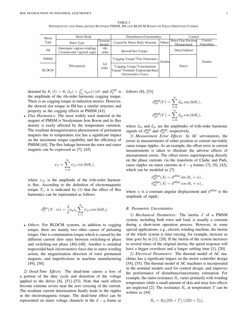
In most parts of the paper, we mainly focus on discussingPMSM system as a benchmark AC drive system. However, itis noticed that PMSM shares many similarities of the problemformulation, disturbance/uncertainty properties and control al-gorithms with a number of other advanced AC motor drives,such as IM, BLDCM, and switched reluctance motors [41].For example, the differences and similarities among three mostpopular AC machine drives (PMSM, IM and BLDCM) arelisted in Table I. In this section as well as several subsequentsections, attention to other AC motors will be paid for theinterest of readers in related areas.
A generic d − q dynamic model of PMSM drives is givenwith respect to its rotor reference frame as
diddt
=1
Ld(ud −Rsid + npωLqiq) ,
diqdt
=1
Lq(uq −Rsiq − npωLdid − npωψf ) ,
dω
dt=
1
J
(Te − dfric
T − dloadT
),
Te =3
2np [ψf iq + (Ld − Lq)idiq] , dfric
T = Bvω,
(1)
TABLE IIDISTURBANCES AND UNCERTAINTIES IN PMSM
Symbol Meaning Unitd
cogT Cogging Torque N ·m
dfluxT Flux Harmonic Torque N ·m
ddeaddV , ddead
qV Distortion Voltage V
doffsetdC , doffset
qC Current Offset Errors A
dfricT Friction Torque N ·m
dloadT Load Torque N ·m
where ω is the rotor speed, id and iq are stator currents ind− q frame, ud and uq denote stator voltages in d− q frame,dloadT represents the load torque disturbance, dfric
T is the frictiontorque disturbance, Te is the electromagnetic torque, Bv isthe frictional coefficient, Ld and Lq are stator inductances ind − q frame, Rs is the stator resistance, ψf is the magneticflux linkage, J is the moment of the total inertial (rotor andload), and np is the number of poles.
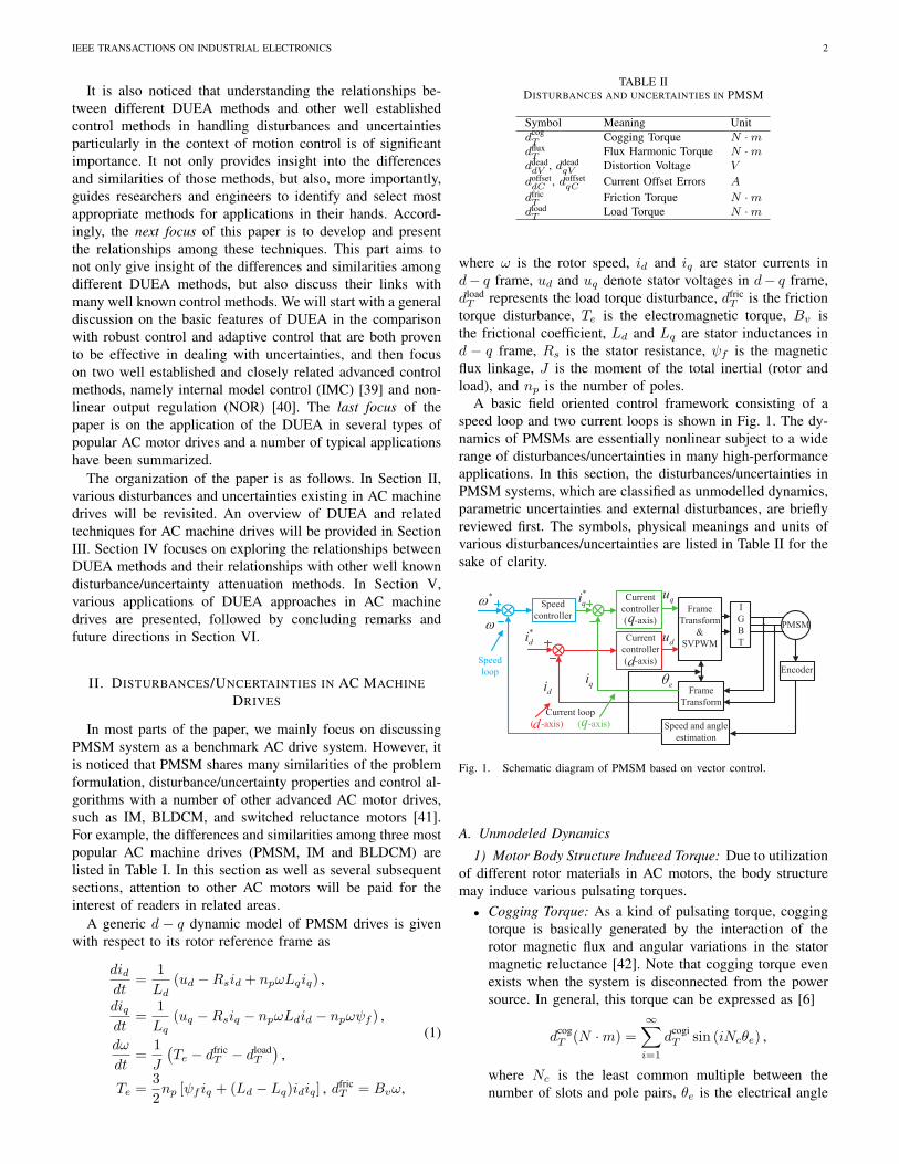
A basic field oriented control framework consisting of aspeed loop and two current loops is shown in Fig. 1. The dy-namics of PMSMs are essentially nonlinear subject to a widerange of disturbances/uncertainties in many high-performanceapplications. In this section, the disturbances/uncertainties inPMSM systems, which are classified as unmodelled dynamics,parametric uncertainties and external disturbances, are brieflyreviewed first. The symbols, physical meanings and units ofvarious disturbances/uncertainties are listed in Table II for thesake of clarity.
Speed
controller
Current
controller
( -axis)
I
G
B
T
PMSM
Encoder
Frame
Transform
Speed and angle
estimation
Frame
Transform
&
SVPWMCurrent
controller
( -axis)
*w
q
d
*
qi
*
di
qidi
qu
du
eq
Speed
loop
Current loop
( -axis) ( -axis)d q
w
Fig. 1. Schematic diagram of PMSM based on vector control.
A. Unmodeled Dynamics
1) Motor Body Structure Induced Torque: Due to utilizationof different rotor materials in AC motors, the body structuremay induce various pulsating torques.
• Cogging Torque: As a kind of pulsating torque, coggingtorque is basically generated by the interaction of therotor magnetic flux and angular variations in the statormagnetic reluctance [42]. Note that cogging torque evenexists when the system is disconnected from the powersource. In general, this torque can be expressed as [6]
dcogT (N ·m) =
∞∑i=1
dcogiT sin (iNcθe) ,
where Nc is the least common multiple between thenumber of slots and pole pairs, θe is the electrical angle
IEEE TRANSACTIONS ON INDUSTRIAL ELECTRONICS 3
TABLE IDIFFERENCES AND SIMILARITIES BETWEEN PMSM, IM AND BLDCM BASED ON FIELD ORIENTED CONROL
Motor
Type
Motor Body
IM
PM material
Rotor TypeDynamic
Models
Disturbances/Uncertainties
Caused by Motor Body Structure Others
PMSM
4th
order
Similar3rd
order
Control
Rotor Flux Position
Measurement
Direct/Indirect
Control
Algorithms
Similar
BLDCM
Direct
1Cogging Torque/2Flux Harmonics
Skewed Slot Torque
1Cogging Torque/2Commutation
Torque/3Nonideal Trapezoidal Back
Electromotive Force
Aluminum/ cuprum windings
(1wound-rotor 2squirrel cage)
denoted by θe (t) = θe (t0) +∫ t
t0npω(τ)dτ and dcogi
T isthe amplitude of the ith-order harmonic cogging torque.There is no cogging torque in induction motors. However,the skewed slot torque in IM has a similar structure andproperty as the cogging effects in PMSM [43].
• Flux Harmonics: The most widely used material in themagnet of PMSM is Neodymium Iron Boron and its fluxdensity is easily affected by the temperature variation.The resultant demagnetization phenomenon of permanentmagnets due to temperature rise has a significant impacton the maximum torque capability and the efficiency ofPMSM [44]. The flux linkage between the rotor and statormagnets can be expressed as [7], [45]
ψf =
∞∑i=0
ψfi cos (6iθe),
where ψfi is the amplitude of the 6ith-order harmon-ic flux. According to the definition of electromagnetictorque Te, it is indicated by (1) that the effect of fluxharmonics can be represented as follows
dfluxT (N ·m) =
3
2npiq
∞∑i=1
ψfi cos (6iθe).
• Others: For BLDCM systems, in addition to coggingtorque, there are mainly two other causes of pulsatingtorque. One is commutation torque which is caused by thedifferent current slew rates between switching-in phaseand switching-out phase [46]–[48]. Another is nonidealtrapezoidal back electromotive force due to stator windingaction, the magnetization direction of rotor permanentmagnets, and imperfections in machine manufacturing[49], [50].
2) Dead-Time Effects: The dead-time causes a loss ofa portion of the duty cycle and distortion of the voltageapplied to the drives [8], [51]–[53]. Note that such effectsbecome extreme severe near the zero crossing of the current.The resultant current deterioration finally leads to the ripplesin the electromagnetic torque. The dead-time effect can berepresented on stator voltage channels in the d − q frame as
follows [8], [53]
ddeaddV (V ) =
∞∑i=0
ddi sin (6iθe) ,
ddeadqV (V ) =
∞∑i=0
dqi cos (6iθe) ,
where ddi and dqi are the amplitudes of 6ith-order harmonicsignals of ddead
dV and ddeadqV , respectively.
3) Measurement Error Effects: In AC servomotors, theerrors in measurements of either position or current inevitablycause torque ripples. As an example, the offset error in currentmeasurements is taken to illustrate the adverse effects ofmeasurement errors. The offset errors superimposing directlyon the phase currents via the transform of Clarke and Park,cause ripples on stator currents in d− q frames [7], [9], [42],which can be modeled as [7]
doffsetdC (A) = doffset sin (θe + α) ,
doffsetqC (A) = doffset cos (θe + α) ,
where α is a constant angular displacement and doffset is theamplitude of ripple.
B. Parametric Uncertainties
1) Mechanical Parameters: The inertia J of a PMSMsystem, including both rotor and load, is usually a constantduring a short-term operation process. However, in somespecial applications, e.g., electric winding machine, the inertiaof the whole system is time-varying, for example, increase astime goes by in [1], [20]. If the inertia of the system increasesto several times of the original inertia, the speed response willhave a bigger overshoot and a longer settling time [1], [20].
2) Electrical Parameters: The thermal model of AC ma-chines has a significant impact on the motor controller design[54], [55]. The thermal model of AC machines is incorporatedin the nominal models used for control design, and improvesthe performance of disturbance/uncertainty estimation. Forexample, the stator resistance Rs varies primarily with windingtemperature while a small amount of skin and stray loss effectsare neglected [2]. The resistance Rs at temperature T can bewritten as [44]
Rs = R0(235 + T )/(235 + T0),
IEEE TRANSACTIONS ON INDUSTRIAL ELECTRONICS 4
where R0 is the resistance at temperature T0. It can beobserved from the PMSM model (1) that the stator resistanceaffects the plant bandwidth of the current loop directly. Assuch, the variation of stator resistance has a great impact on thecurrent-loop regulation performance. Moreover, the resistanceeffect becomes much severe at low speeds or in high loadtorque conditions [2], [3], [56].
In addition, the stator inductances Ld and Lq are hard toprecisely obtain [57], and they are usually functions of currentmagnitude and current phase angle of the motor [2], [4]. Forinstance, the effects of cross saturation [58] generally resultin variations of stator inductances which affects both the plantgain and the open-loop electrical time constant of the motor,and hence, the performance of the drives at different operatingconditions.
C. External Disturbances
1) Friction Torque: Friction is the tangential reaction forcebetween two surfaces in contact [59]. It can be representedby static models (the Coulomb model, the Stribeck model,the Karnppp model, etc.) and dynamic models (the Dahlmodel, the Bristle model, the reset integrator model, and theLuGre model, etc.) [59]. The nonlinear effects of friction areunavoidable and widely exist in servo systems, which maycause steady-state errors, tracking lags and limit cycles inposition regulation [59], [60]. Taking the Stribeck model asan example, the friction torque dfric
T is expressed as [59]
dfricT (N ·m) =
(Tc + (Ts − Tc) e
−( ωωs)2)
sign (ω) +Bvω,
where Ts is the static friction torque, Tc is the Coulombfriction torque, ωs is the Stribeck velocity, and sign (•) is thestandard signum function.
2) Load Torque: Torque on the load side is generallydeemed as one of the most severe disturbances affecting thedynamic performance. For example, since the transmissionmechanism is not an ideal rigid body, mechanical resonancecan be easily excited due to the load torque [10]. Speed isinevitably changed when load torque is imposed on the motor.
3) Mechanical Factors: The effects raised by mechanicalcharacteristics such as torsional vibrations, backlash, and un-certainties generated by misalignment of shaft, broken shaftand twisted shaft are another branch of causes restricting servoperformance improvement of motor drives [61]. It is estimatedthat the misalignment of shaft causes over 70% of rotatingmachinery’s vibration problems in industrial motor drives [62].
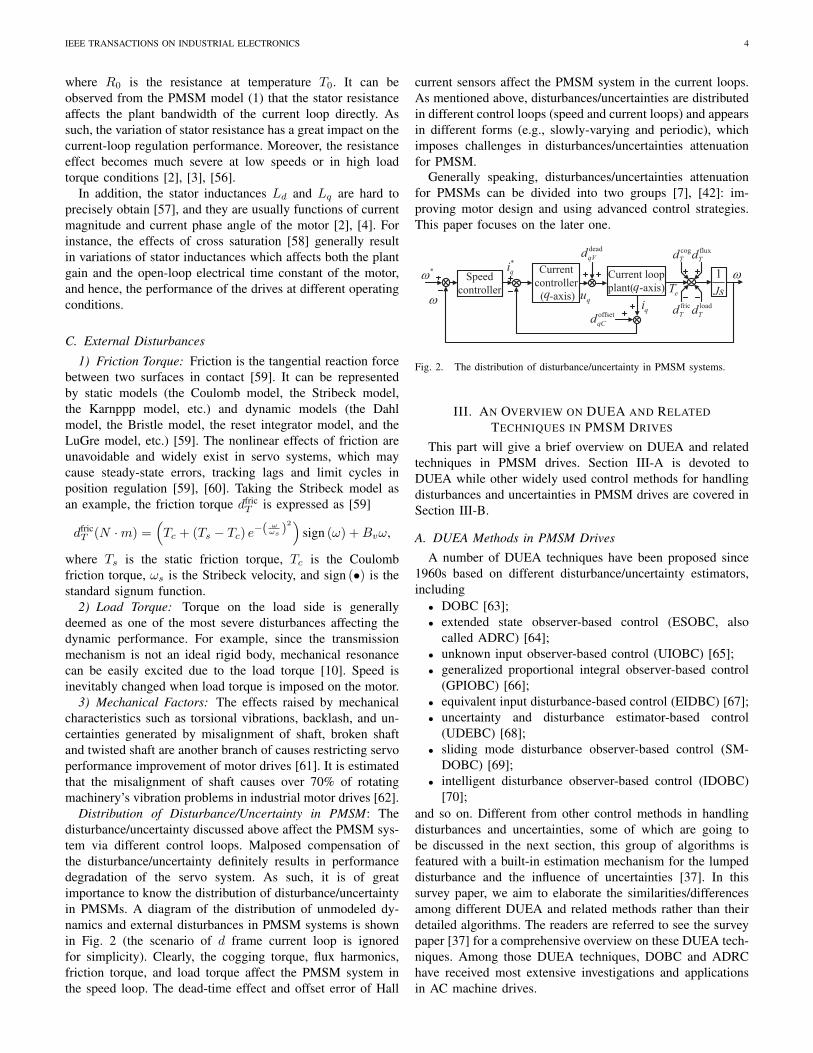
Distribution of Disturbance/Uncertainty in PMSM: Thedisturbance/uncertainty discussed above affect the PMSM sys-tem via different control loops. Malposed compensation ofthe disturbance/uncertainty definitely results in performancedegradation of the servo system. As such, it is of greatimportance to know the distribution of disturbance/uncertaintyin PMSMs. A diagram of the distribution of unmodeled dy-namics and external disturbances in PMSM systems is shownin Fig. 2 (the scenario of d frame current loop is ignoredfor simplicity). Clearly, the cogging torque, flux harmonics,friction torque, and load torque affect the PMSM system inthe speed loop. The dead-time effect and offset error of Hall
current sensors affect the PMSM system in the current loops.As mentioned above, disturbances/uncertainties are distributedin different control loops (speed and current loops) and appearsin different forms (e.g., slowly-varying and periodic), whichimposes challenges in disturbances/uncertainties attenuationfor PMSM.
Generally speaking, disturbances/uncertainties attenuationfor PMSMs can be divided into two groups [7], [42]: im-proving motor design and using advanced control strategies.This paper focuses on the later one.
Speed
controller
Current
controller
( -axis)
Current loop
plant( -axis)
*w
q
*
qi
qiqu
eTw
qw
1
Js
cog
Tdflux
Td
offset
qCd
fric
Tdload
Td
dead
qVd
Fig. 2. The distribution of disturbance/uncertainty in PMSM systems.
III. AN OVERVIEW ON DUEA AND RELATEDTECHNIQUES IN PMSM DRIVES
This part will give a brief overview on DUEA and relatedtechniques in PMSM drives. Section III-A is devoted toDUEA while other widely used control methods for handlingdisturbances and uncertainties in PMSM drives are covered inSection III-B.
A. DUEA Methods in PMSM DrivesA number of DUEA techniques have been proposed since
1960s based on different disturbance/uncertainty estimators,including
• DOBC [63];• extended state observer-based control (ESOBC, also
called ADRC) [64];• unknown input observer-based control (UIOBC) [65];• generalized proportional integral observer-based control
(GPIOBC) [66];• equivalent input disturbance-based control (EIDBC) [67];• uncertainty and disturbance estimator-based control
(UDEBC) [68];• sliding mode disturbance observer-based control (SM-
DOBC) [69];• intelligent disturbance observer-based control (IDOBC)
[70];and so on. Different from other control methods in handlingdisturbances and uncertainties, some of which are going tobe discussed in the next section, this group of algorithms isfeatured with a built-in estimation mechanism for the lumpeddisturbance and the influence of uncertainties [37]. In thissurvey paper, we aim to elaborate the similarities/differencesamong different DUEA and related methods rather than theirdetailed algorithms. The readers are referred to see the surveypaper [37] for a comprehensive overview on these DUEA tech-niques. Among those DUEA techniques, DOBC and ADRChave received most extensive investigations and applicationsin AC machine drives.
IEEE TRANSACTIONS ON INDUSTRIAL ELECTRONICS 5
1) DOBC: As a key component of DOBC, DOB wasinitiatively put forward by K. Ohnishi and his colleagues in1980s to improve disturbance rejection and robustness in DCmotors [63]. The early DOBC was designed on the basis offrequency-domain control theory. With the prevalence of statespace design approaches for DOBC, nonlinear DOBC hasattracted a great deal of attentions so as to further enhance thecontrol performances of essential nonlinear dynamic systems.In what follows, we will try to illustrate the basic principlesof typical frequency-domain DOBC and nonlinear DOBC viatwo benchmark design examples of the speed regulation of thePMSM system.
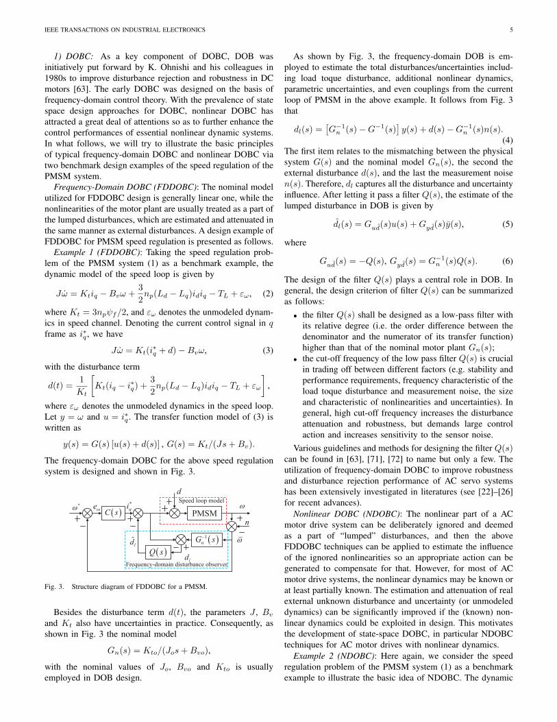
Frequency-Domain DOBC (FDDOBC): The nominal modelutilized for FDDOBC design is generally linear one, while thenonlinearities of the motor plant are usually treated as a part ofthe lumped disturbances, which are estimated and attenuated inthe same manner as external disturbances. A design example ofFDDOBC for PMSM speed regulation is presented as follows.
Example 1 (FDDOBC): Taking the speed regulation prob-lem of the PMSM system (1) as a benchmark example, thedynamic model of the speed loop is given by
Jω = Ktiq −Bvω +3
2np(Ld − Lq)idiq − TL + εω, (2)
where Kt = 3npψf/2, and εω denotes the unmodeled dynam-ics in speed channel. Denoting the current control signal in qframe as i∗q , we have
Jω = Kt(i∗q + d)−Bvω, (3)
with the disturbance term
d(t) =1
Kt
[Kt(iq − i∗q) +
3
2np(Ld − Lq)idiq − TL + εω
],
where εω denotes the unmodeled dynamics in the speed loop.Let y = ω and u = i∗q . The transfer function model of (3) iswritten as
y(s) = G(s) [u(s) + d(s)] , G(s) = Kt/(Js+Bv).
The frequency-domain DOBC for the above speed regulationsystem is designed and shown in Fig. 3.
Frequency-domain disturbance observer
Speed loop model*w ew
*
qi
ˆld
ld
w
n( )C s
( )Q s
( )1
nG s- w
*w *
di
Controller
u( )g x d
x
PMSM
PMSM( )1g x
]2 1l g p z f g u
( )p x
òz z
p
d
PMSM
dw
bqu
Controller
ˆ( )Ax Bu L Cx+ + -òx x
1/ b
3Ed
*w
*w w*
qi( )C s( )R s PMSM
d
( )G s
( )F s
d
Fig. 3. Structure diagram of FDDOBC for a PMSM.
Besides the disturbance term d(t), the parameters J , Bv
and Kt also have uncertainties in practice. Consequently, asshown in Fig. 3 the nominal model
Gn(s) = Kto/(Jos+Bvo),
with the nominal values of Jo, Bvo and Kto is usuallyemployed in DOB design.
As shown by Fig. 3, the frequency-domain DOB is em-ployed to estimate the total disturbances/uncertainties includ-ing load toque disturbance, additional nonlinear dynamics,parametric uncertainties, and even couplings from the currentloop of PMSM in the above example. It follows from Fig. 3that
dl(s) =[G−1
n (s)−G−1(s)]y(s) + d(s)−G−1
n (s)n(s).(4)
The first item relates to the mismatching between the physicalsystem G(s) and the nominal model Gn(s), the second theexternal disturbance d(s), and the last the measurement noisen(s). Therefore, dl captures all the disturbance and uncertaintyinfluence. After letting it pass a filter Q(s), the estimate of thelumped disturbance in DOB is given by
dl(s) = Gud(s)u(s) +Gyd(s)y(s), (5)
where
Gud(s) = −Q(s), Gyd(s) = G−1n (s)Q(s). (6)
The design of the filter Q(s) plays a central role in DOB. Ingeneral, the design criterion of filter Q(s) can be summarizedas follows:
• the filter Q(s) shall be designed as a low-pass filter withits relative degree (i.e. the order difference between thedenominator and the numerator of its transfer function)higher than that of the nominal motor plant Gn(s);
• the cut-off frequency of the low pass filter Q(s) is crucialin trading off between different factors (e.g. stability andperformance requirements, frequency characteristic of theload toque disturbance and measurement noise, the sizeand characteristic of nonlinearities and uncertainties). Ingeneral, high cut-off frequency increases the disturbanceattenuation and robustness, but demands large controlaction and increases sensitivity to the sensor noise.
Various guidelines and methods for designing the filter Q(s)can be found in [63], [71], [72] to name but only a few. Theutilization of frequency-domain DOBC to improve robustnessand disturbance rejection performance of AC servo systemshas been extensively investigated in literatures (see [22]–[26]for recent advances).
Nonlinear DOBC (NDOBC): The nonlinear part of a ACmotor drive system can be deliberately ignored and deemedas a part of “lumped” disturbances, and then the aboveFDDOBC techniques can be applied to estimate the influenceof the ignored nonlinearities so an appropriate action can begenerated to compensate for that. However, for most of ACmotor drive systems, the nonlinear dynamics may be known orat least partially known. The estimation and attenuation of realexternal unknown disturbance and uncertainty (or unmodeleddynamics) can be significantly improved if the (known) non-linear dynamics could be exploited in design. This motivatesthe development of state-space DOBC, in particular NDOBCtechniques for AC motor drives with nonlinear dynamics.
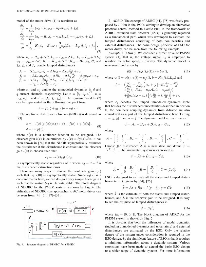
Example 2 (NDOBC): Here again, we consider the speedregulation problem of the PMSM system (1) as a benchmarkexample to illustrate the basic idea of NDOBC. The dynamic
IEEE TRANSACTIONS ON INDUSTRIAL ELECTRONICS 6
model of the motor drive (1) is rewritten asdiddt
=1
Ldo(ud −Rsoid + npωLqoiq + fd) ,
diqdt
=1
Lqo(uq −Rsoiq − npωLdoid − npωψfo + fq) ,
dω
dt=
1
Jo
[Ktoiq −Bvoω +
3
2np(Ldo − Lqo)idiq + fω
],
(7)
where Rs = Rso +∆R; Ld = Ldo +∆Ld; Lq = Lqo +∆Lq;ψf = ψfo + ∆ψ; Kt = Kto + ∆K; Kto = 3npψfo/2; andfd, fq and fω denote lumped disturbances
fd = ∆Lqonpωiq −∆Rid −∆Lddiddt + εd,
fq = −∆Ldonpωid −∆Riq −∆Lqdiqdt −∆ψnpω + εq ,
fω = ∆Kiq +32np (∆Ld −∆Lq) idiq −∆Bvω
−TL −∆J dωdt + εω.
where εd and εq denote the unmodeled dynamics in d andq current channels, respectively. Let x = [id, iq , ω]⊤, u =
[ud, uq]⊤ and d = [fd, fq , fω]
⊤. The dynamic models (7)can be represented in the following compact form
x = f(x) + g1(x)u+ g2(x)d. (8)
The nonlinear disturbance observer (NDOB) is designed as[73]
z =− l(x) [g2(x)(p(x) + z) + f(x) + g1(x)u] ,
d =z + p(x),(9)
where p(x) is a nonlinear function to be designed. Theobserver gain l(x) is determined by l(x) = ∂p(x)/∂x. It hasbeen shown in [74] that the NDOB asymptotically estimatesthe disturbance if the disturbance is constant and the observergain l(x) is chosen such that
ed = −l(x)g2(x)ed, (10)
is asymptotically stable regardless of x where ed = d − d isthe disturbance estimation error.
There are many ways to choose the nonlinear gain l(x)such that Eq. (10) is asymptotically stable. Since g2(x) is aconstant matrix here, we can design a very simple linear gain lsuch that the matrix lg2 is Hurwitz stable. The block diagramof NDOBC for the PMSM system is shown by Fig. 4. Theutilization of NDOBC-like approaches to AC motor drives canbe seen from [4], [5], [27]–[32].
Sate space model
Nonlinear disturbance observer
Fig. 4. Structure diagram of NDOBC for a PMSM.
2) ADRC: The concept of ADRC [64], [75] was firstly pro-posed by J. Han in the 1990s, aiming to develop an alternativepractical control method to classic PID. In the framework ofADRC, extended state observer (ESO) is generally regardedas a fundamental part, which was developed to estimate thelumped disturbances consisting of both nonlinearities andexternal disturbances. The basic design principle of ESO formotor drives can be seen from the following example.
Example 3 (ADRC): We consider a direct drive of PMSMsystem (1), that is, the voltage signal uq is employed toregulate the rotor speed ω directly. The dynamic model isrearranged and given by
y(t) = f(y(t),y(t),t) + bu(t), (11)
where y(t) = ω(t), u(t) = uq(t), b = Kto/(JoLqo) and
f =(
Kt
JLq− Kto
JoLqo
)uq +
1J
[−Bv
dωdt − dTL
dt
+Kt
Lq(−Rsiq − npωLdid − npωψf )
+32np(Ld − Lq)
(id
diqdt + iq
diddt
)]+ εf ,
where εf denotes the lumped unmodeled dynamics. Notethat besides the disturbances/uncertainties described in SectionII, the nonlinear coupling dynamics from d-frame are alsoconsidered as a part of the lumped disturbance here. Lettingx = [y, y]⊤ and d = f , the dynamic model is rewritten as
x = Ax+Buu+Bdd, y = Cx, (12)
where
A =
[0 10 0
], Bu =
[0b
], Bd =
[01
], C =
[10
]⊤.
Choose the disturbance d as a new state and define x =[x⊤, d
]⊤. The augmented system is expressed as
˙x = Ax+ Bu, y = Cx, (13)
where
A =
[A Bd
0 0
], B =
[Bu
0
], C = [C, 0]. (14)
ESO is designed to estimate all the states and lumped distur-bance term f , given by [64], [75]
˙x = Aˆx+ Bu+ L(y − y), y = C ˆx, (15)
where ˆx is the estimate of both the states and lumped distur-bances, and L is the observer gain to be designed. It is easyto see the estimate of lumped disturbances is
d = E3 ˆx, (16)
where E3 = [0, 0, 1]. The block diagram of ADRC for thePMSM system is shown by Fig. 5.
It is obvious that both the influences of model dynamics(including unmodelled dynamics and uncertainty) and externaldisturbances are estimated by the ESO. Only the relativedegree of the system under consideration is required in theESO design. So the significant feature of ESO is that it requiresa minimum information about a dynamic system. Variousextensions have been made to extend the basic ESO designto a wider range of dynamic systems. For more information
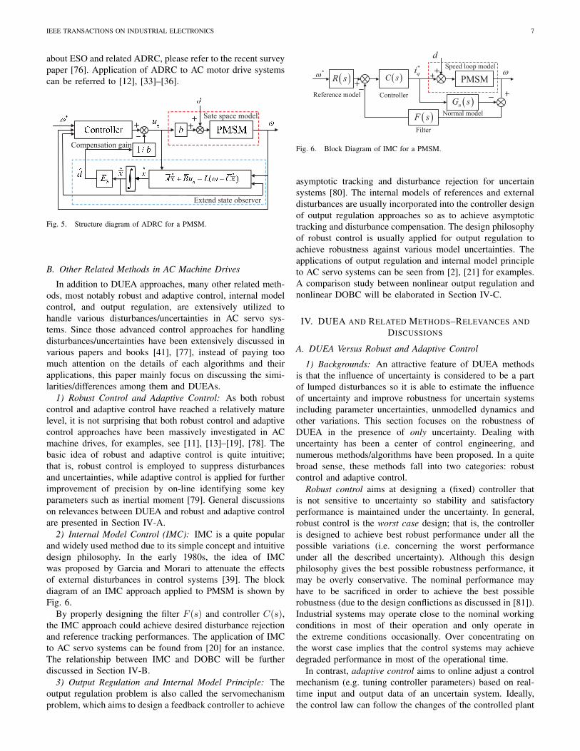
IEEE TRANSACTIONS ON INDUSTRIAL ELECTRONICS 7
about ESO and related ADRC, please refer to the recent surveypaper [76]. Application of ADRC to AC motor drive systemscan be referred to [12], [33]–[36].
Sate space model
Extend state observer
Compensation gain
Fig. 5. Structure diagram of ADRC for a PMSM.
B. Other Related Methods in AC Machine Drives
In addition to DUEA approaches, many other related meth-ods, most notably robust and adaptive control, internal modelcontrol, and output regulation, are extensively utilized tohandle various disturbances/uncertainties in AC servo sys-tems. Since those advanced control approaches for handlingdisturbances/uncertainties have been extensively discussed invarious papers and books [41], [77], instead of paying toomuch attention on the details of each algorithms and theirapplications, this paper mainly focus on discussing the simi-larities/differences among them and DUEAs.
1) Robust Control and Adaptive Control: As both robustcontrol and adaptive control have reached a relatively maturelevel, it is not surprising that both robust control and adaptivecontrol approaches have been massively investigated in ACmachine drives, for examples, see [11], [13]–[19], [78]. Thebasic idea of robust and adaptive control is quite intuitive;that is, robust control is employed to suppress disturbancesand uncertainties, while adaptive control is applied for furtherimprovement of precision by on-line identifying some keyparameters such as inertial moment [79]. General discussionson relevances between DUEA and robust and adaptive controlare presented in Section IV-A.
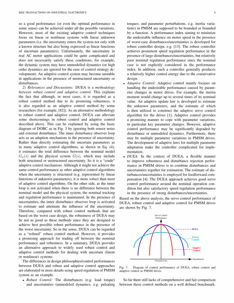
2) Internal Model Control (IMC): IMC is a quite popularand widely used method due to its simple concept and intuitivedesign philosophy. In the early 1980s, the idea of IMCwas proposed by Garcia and Morari to attenuate the effectsof external disturbances in control systems [39]. The blockdiagram of an IMC approach applied to PMSM is shown byFig. 6.
By properly designing the filter F (s) and controller C(s),the IMC approach could achieve desired disturbance rejectionand reference tracking performances. The application of IMCto AC servo systems can be found from [20] for an instance.The relationship between IMC and DOBC will be furtherdiscussed in Section IV-B.
3) Output Regulation and Internal Model Principle: Theoutput regulation problem is also called the servomechanismproblem, which aims to design a feedback controller to achieve
Speed loop model
Reference model
Filter
Normal model
Controller
( )C s( )R s
( )nG s
( )F s
*w*
qi
d
wPMSM
Fig. 6. Block Diagram of IMC for a PMSM.
asymptotic tracking and disturbance rejection for uncertainsystems [80]. The internal models of references and externaldisturbances are usually incorporated into the controller designof output regulation approaches so as to achieve asymptotictracking and disturbance compensation. The design philosophyof robust control is usually applied for output regulation toachieve robustness against various model uncertainties. Theapplications of output regulation and internal model principleto AC servo systems can be seen from [2], [21] for examples.A comparison study between nonlinear output regulation andnonlinear DOBC will be elaborated in Section IV-C.
IV. DUEA AND RELATED METHODS–RELEVANCES ANDDISCUSSIONS
A. DUEA Versus Robust and Adaptive Control
1) Backgrounds: An attractive feature of DUEA methodsis that the influence of uncertainty is considered to be a partof lumped disturbances so it is able to estimate the influenceof uncertainty and improve robustness for uncertain systemsincluding parameter uncertainties, unmodelled dynamics andother variations. This section focuses on the robustness ofDUEA in the presence of only uncertainty. Dealing withuncertainty has been a center of control engineering, andnumerous methods/algorithms have been proposed. In a quitebroad sense, these methods fall into two categories: robustcontrol and adaptive control.
Robust control aims at designing a (fixed) controller thatis not sensitive to uncertainty so stability and satisfactoryperformance is maintained under the uncertainty. In general,robust control is the worst case design; that is, the controlleris designed to achieve best robust performance under all thepossible variations (i.e. concerning the worst performanceunder all the described uncertainty). Although this designphilosophy gives the best possible robustness performance, itmay be overly conservative. The nominal performance mayhave to be sacrificed in order to achieve the best possiblerobustness (due to the design conflictions as discussed in [81]).Industrial systems may operate close to the nominal workingconditions in most of their operation and only operate inthe extreme conditions occasionally. Over concentrating onthe worst case implies that the control systems may achievedegraded performance in most of the operational time.
In contrast, adaptive control aims to online adjust a controlmechanism (e.g. tuning controller parameters) based on real-time input and output data of an uncertain system. Ideally,the control law can follow the changes of the controlled plant
IEEE TRANSACTIONS ON INDUSTRIAL ELECTRONICS 8
so a good performance (or even the optimal performance insome sense) can be achieved under all the possible variations.However, most of the existing adaptive control techniquesfocus on linear or nonlinear systems with linear unknownparameters (i.e. the uncertainty enters the system not only witha known structure but also being expressed as linear functionsof uncertain parameters). Unfortunately, the uncertainty inreal AC motor applications could be quite complicated anddoes not necessarily satisfy these conditions; for example,the dynamic system may have unmodelled dynamics (or highorder dynamics are ignored for the ease of control strategy de-velopment). An adaptive control system may become unstablein applications in the presence of unstructured uncertainty ordisturbances.
2) Relevances and Discussions: DUEA is a methodologybetween robust control and adaptive control. This explainsthe fact that although, in most cases, it is regarded as arobust control method due to its promising robustness, itis also regarded as an adaptive control method by someresearchers (for example, [82]). As an alternative methodologyto robust control and adaptive control, DUEA can alleviatesome shortcomings in robust control and adaptive controldescribed above. This can be explained by using the basicdiagram of DOBC as in Fig. 3 by ignoring both sensor noiseand external disturbance. The inner disturbance observer loopacts as an adaption mechanism in the presence of uncertainty.Rather than directly estimating the uncertain parameters asin many adaptive control algorithms, as shown in Eq. (4),it estimates the total difference between the nominal modelGn(s) and the physical system G(s), which may includeboth structured or unstructured uncertainty. So it is a “crude”adaptive control mechanism. Although it might not achieve thesame control performance as other adaptive control algorithmswhen the uncertainty is structured (e.g. represented by linearfunctions of unknown parameters), it is more robust than mostof adaptive control algorithms. On the other side, as the innerloop is not activated when there is no difference between thenominal model and the physical system, the nominal trackingand regulation performance is maintained. In the presence ofuncertainties, the inner disturbance observer loop is activatedto estimate and attenuate the influence of the uncertainty.Therefore, compared with robust control methods that arebased on the worst case design, the robustness of DUEA maybe not as good as these methods since they are designed toachieve best possible robust performance in the presence ofthe worst uncertainty. So in the sense, DUEA can be regardedas a “refined” robust control method. However, it providesa promising approach for trading off between the nominalperformance and robustness. In a summary, DUEA providesan alternative approach to widely used robust control andadaptive control methods for dealing with uncertain (linearor nonlinear) systems.
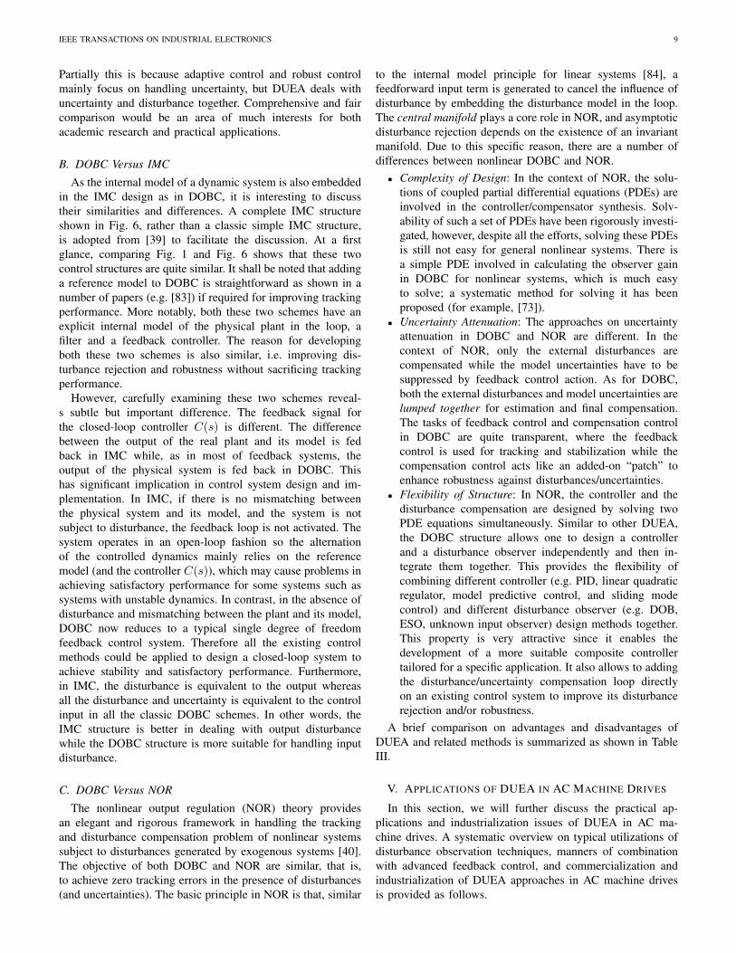
The differences in design philosophies/control performancesbetween DUEA and robust and adaptive control approachesare elaborated in more details using speed regulation of PMSMsystem as an example.
• Robust Control: The disturbances (e.g. load torque)and uncertainties (unmodeled dynamics, e.g. pulsating
torques; and parameter perturbations, e.g. inertia varia-tions) in PMSM are supposed to be bounded or boundedby a function. A performance index aiming to minimizethe undesirable influence on motor speed in the presenceof worst-case disturbances/uncertainties is developed forrobust controller design, e.g. [13]. The robust controllerachieves prominent speed regulation performance in thepresence of large disturbances/uncertainties, but relativelypoor nominal regulation performance since the nominalcase is not explicitly considered in the performanceindex. In addition, such a controller generally producesa relatively higher control energy due to the conservativedesign.
• Adaptive Control: Adaptive control mainly focuses onhandling the undesirable performance caused by param-eter changes in motor drives. For example, the inertiamoment would change up to several times of its nominalvalue. An adaptive update law is developed to estimatethe unknown parameters, and the estimate of whichis then utilized to construct the adaptive servo controlalgorithm for the drives [1]. Adaptive control providesa promising manner to cope with parameter variations,in particular key parameter changes. However, adaptivecontrol performance may be significantly degraded bydisturbance or unmodeled dynamics. Furthermore, theremay be multiple parameter variations in PMSM drives.The development of adaptive laws for multiple parameteradaptation make the controller complicated for imple-mentation.
• DUEA: In the context of DUEA, a flexible mannerto improve robustness and disturbance rejection perfor-mance in PMSM drives is to combine disturbances anduncertainties together for estimation. The estimate of dis-turbances/uncertainties is employed for feedforward com-pensation [4]. The DUEA approach achieves good servocontrol performance around the nominal operation con-dition but also satisfactory speed regulation performancein the presence of strong disturbances/uncertainties.
Based on the above analysis, the servo control performance ofDUEA, robust control and adaptive control for PMSM drivesare shown by Fig. 7.
Servo Control
Performance
DUEA
Robust
Control
Adaptive
Control
Nominal CaseDisturbances
Fig. 7. Diagram of control performance of DUEA, robust control andadaptive control in PMSM drives.
So far there still lacks of comprehensive and fair comparisonbetween these control methods on a well defined benchmark.
IEEE TRANSACTIONS ON INDUSTRIAL ELECTRONICS 9
Partially this is because adaptive control and robust controlmainly focus on handling uncertainty, but DUEA deals withuncertainty and disturbance together. Comprehensive and faircomparison would be an area of much interests for bothacademic research and practical applications.
B. DOBC Versus IMC
As the internal model of a dynamic system is also embeddedin the IMC design as in DOBC, it is interesting to discusstheir similarities and differences. A complete IMC structureshown in Fig. 6, rather than a classic simple IMC structure,is adopted from [39] to facilitate the discussion. At a firstglance, comparing Fig. 1 and Fig. 6 shows that these twocontrol structures are quite similar. It shall be noted that addinga reference model to DOBC is straightforward as shown in anumber of papers (e.g. [83]) if required for improving trackingperformance. More notably, both these two schemes have anexplicit internal model of the physical plant in the loop, afilter and a feedback controller. The reason for developingboth these two schemes is also similar, i.e. improving dis-turbance rejection and robustness without sacrificing trackingperformance.
However, carefully examining these two schemes reveal-s subtle but important difference. The feedback signal forthe closed-loop controller C(s) is different. The differencebetween the output of the real plant and its model is fedback in IMC while, as in most of feedback systems, theoutput of the physical system is fed back in DOBC. Thishas significant implication in control system design and im-plementation. In IMC, if there is no mismatching betweenthe physical system and its model, and the system is notsubject to disturbance, the feedback loop is not activated. Thesystem operates in an open-loop fashion so the alternationof the controlled dynamics mainly relies on the referencemodel (and the controller C(s)), which may cause problems inachieving satisfactory performance for some systems such assystems with unstable dynamics. In contrast, in the absence ofdisturbance and mismatching between the plant and its model,DOBC now reduces to a typical single degree of freedomfeedback control system. Therefore all the existing controlmethods could be applied to design a closed-loop system toachieve stability and satisfactory performance. Furthermore,in IMC, the disturbance is equivalent to the output whereasall the disturbance and uncertainty is equivalent to the controlinput in all the classic DOBC schemes. In other words, theIMC structure is better in dealing with output disturbancewhile the DOBC structure is more suitable for handling inputdisturbance.
C. DOBC Versus NOR
The nonlinear output regulation (NOR) theory providesan elegant and rigorous framework in handling the trackingand disturbance compensation problem of nonlinear systemssubject to disturbances generated by exogenous systems [40].The objective of both DOBC and NOR are similar, that is,to achieve zero tracking errors in the presence of disturbances(and uncertainties). The basic principle in NOR is that, similar
to the internal model principle for linear systems [84], afeedforward input term is generated to cancel the influence ofdisturbance by embedding the disturbance model in the loop.The central manifold plays a core role in NOR, and asymptoticdisturbance rejection depends on the existence of an invariantmanifold. Due to this specific reason, there are a number ofdifferences between nonlinear DOBC and NOR.
• Complexity of Design: In the context of NOR, the solu-tions of coupled partial differential equations (PDEs) areinvolved in the controller/compensator synthesis. Solv-ability of such a set of PDEs have been rigorously investi-gated, however, despite all the efforts, solving these PDEsis still not easy for general nonlinear systems. There isa simple PDE involved in calculating the observer gainin DOBC for nonlinear systems, which is much easyto solve; a systematic method for solving it has beenproposed (for example, [73]).
• Uncertainty Attenuation: The approaches on uncertaintyattenuation in DOBC and NOR are different. In thecontext of NOR, only the external disturbances arecompensated while the model uncertainties have to besuppressed by feedback control action. As for DOBC,both the external disturbances and model uncertainties arelumped together for estimation and final compensation.The tasks of feedback control and compensation controlin DOBC are quite transparent, where the feedbackcontrol is used for tracking and stabilization while thecompensation control acts like an added-on “patch” toenhance robustness against disturbances/uncertainties.
• Flexibility of Structure: In NOR, the controller and thedisturbance compensation are designed by solving twoPDE equations simultaneously. Similar to other DUEA,the DOBC structure allows one to design a controllerand a disturbance observer independently and then in-tegrate them together. This provides the flexibility ofcombining different controller (e.g. PID, linear quadraticregulator, model predictive control, and sliding modecontrol) and different disturbance observer (e.g. DOB,ESO, unknown input observer) design methods together.This property is very attractive since it enables thedevelopment of a more suitable composite controllertailored for a specific application. It also allows to addingthe disturbance/uncertainty compensation loop directlyon an existing control system to improve its disturbancerejection and/or robustness.
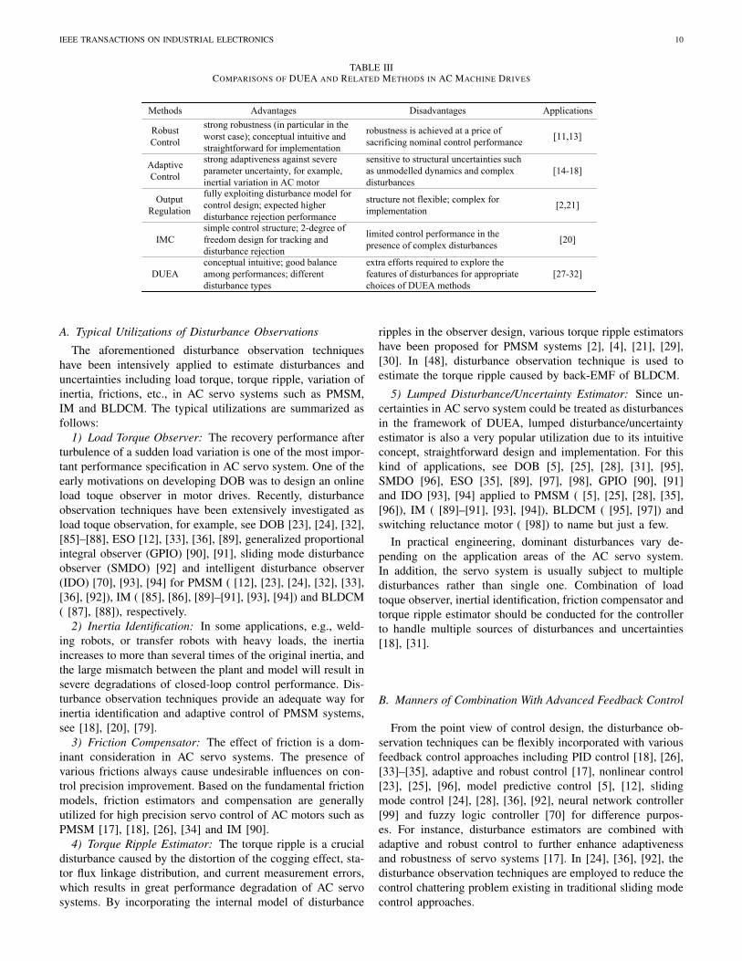
A brief comparison on advantages and disadvantages ofDUEA and related methods is summarized as shown in TableIII.
V. APPLICATIONS OF DUEA IN AC MACHINE DRIVES
In this section, we will further discuss the practical ap-plications and industrialization issues of DUEA in AC ma-chine drives. A systematic overview on typical utilizations ofdisturbance observation techniques, manners of combinationwith advanced feedback control, and commercialization andindustrialization of DUEA approaches in AC machine drivesis provided as follows.
IEEE TRANSACTIONS ON INDUSTRIAL ELECTRONICS 10
TABLE IIICOMPARISONS OF DUEA AND RELATED METHODS IN AC MACHINE DRIVES
Methods Advantages Disadvantages Applications
Robust
Control
strong robustness (in particular in the
worst case); conceptual intuitive and
straightforward for implementation
robustness is achieved at a price of
sacrificing nominal control performance
Adaptive
Control
strong adaptiveness against severe
parameter uncertainty, for example,
inertial variation in AC motor
sensitive to structural uncertainties such
as unmodelled dynamics and complex
disturbances
Output
Regulation
fully exploiting disturbance model for
control design; expected higher
disturbance rejection performance
structure not flexible; complex for
implementation
IMC
simple control structure; 2-degree of
freedom design for tracking and
disturbance rejection
limited control performance in the
presence of complex disturbances
DUEA
conceptual intuitive; good balance
among performances; different
disturbance types
extra efforts required to explore the
features of disturbances for appropriate
choices of DUEA methods
[11,13]
[14-18]
[20]
[2,21]
[27-32]
A. Typical Utilizations of Disturbance Observations
The aforementioned disturbance observation techniqueshave been intensively applied to estimate disturbances anduncertainties including load torque, torque ripple, variation ofinertia, frictions, etc., in AC servo systems such as PMSM,IM and BLDCM. The typical utilizations are summarized asfollows:
1) Load Torque Observer: The recovery performance afterturbulence of a sudden load variation is one of the most impor-tant performance specification in AC servo system. One of theearly motivations on developing DOB was to design an onlineload toque observer in motor drives. Recently, disturbanceobservation techniques have been extensively investigated asload toque observation, for example, see DOB [23], [24], [32],[85]–[88], ESO [12], [33], [36], [89], generalized proportionalintegral observer (GPIO) [90], [91], sliding mode disturbanceobserver (SMDO) [92] and intelligent disturbance observer(IDO) [70], [93], [94] for PMSM ( [12], [23], [24], [32], [33],[36], [92]), IM ( [85], [86], [89]–[91], [93], [94]) and BLDCM( [87], [88]), respectively.
2) Inertia Identification: In some applications, e.g., weld-ing robots, or transfer robots with heavy loads, the inertiaincreases to more than several times of the original inertia, andthe large mismatch between the plant and model will result insevere degradations of closed-loop control performance. Dis-turbance observation techniques provide an adequate way forinertia identification and adaptive control of PMSM systems,see [18], [20], [79].
3) Friction Compensator: The effect of friction is a dom-inant consideration in AC servo systems. The presence ofvarious frictions always cause undesirable influences on con-trol precision improvement. Based on the fundamental frictionmodels, friction estimators and compensation are generallyutilized for high precision servo control of AC motors such asPMSM [17], [18], [26], [34] and IM [90].
4) Torque Ripple Estimator: The torque ripple is a crucialdisturbance caused by the distortion of the cogging effect, sta-tor flux linkage distribution, and current measurement errors,which results in great performance degradation of AC servosystems. By incorporating the internal model of disturbance
ripples in the observer design, various torque ripple estimatorshave been proposed for PMSM systems [2], [4], [21], [29],[30]. In [48], disturbance observation technique is used toestimate the torque ripple caused by back-EMF of BLDCM.
5) Lumped Disturbance/Uncertainty Estimator: Since un-certainties in AC servo system could be treated as disturbancesin the framework of DUEA, lumped disturbance/uncertaintyestimator is also a very popular utilization due to its intuitiveconcept, straightforward design and implementation. For thiskind of applications, see DOB [5], [25], [28], [31], [95],SMDO [96], ESO [35], [89], [97], [98], GPIO [90], [91]and IDO [93], [94] applied to PMSM ( [5], [25], [28], [35],[96]), IM ( [89]–[91], [93], [94]), BLDCM ( [95], [97]) andswitching reluctance motor ( [98]) to name but just a few.
In practical engineering, dominant disturbances vary de-pending on the application areas of the AC servo system.In addition, the servo system is usually subject to multipledisturbances rather than single one. Combination of loadtoque observer, inertial identification, friction compensator andtorque ripple estimator should be conducted for the controllerto handle multiple sources of disturbances and uncertainties[18], [31].
B. Manners of Combination With Advanced Feedback Control
From the point view of control design, the disturbance ob-servation techniques can be flexibly incorporated with variousfeedback control approaches including PID control [18], [26],[33]–[35], adaptive and robust control [17], nonlinear control[23], [25], [96], model predictive control [5], [12], slidingmode control [24], [28], [36], [92], neural network controller[99] and fuzzy logic controller [70] for difference purpos-es. For instance, disturbance estimators are combined withadaptive and robust control to further enhance adaptivenessand robustness of servo systems [17]. In [24], [36], [92], thedisturbance observation techniques are employed to reduce thecontrol chattering problem existing in traditional sliding modecontrol approaches.
IEEE TRANSACTIONS ON INDUSTRIAL ELECTRONICS 11
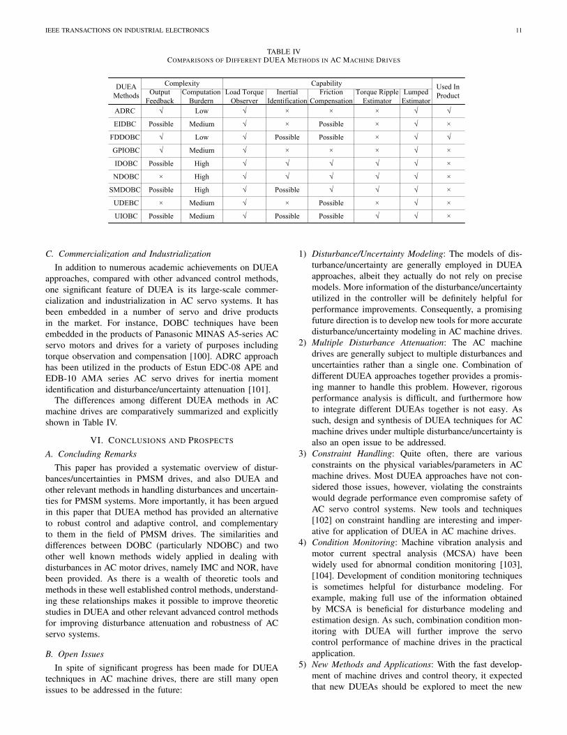
TABLE IVCOMPARISONS OF DIFFERENT DUEA METHODS IN AC MACHINE DRIVES
DUEA
Methods
ComplexityUsed In
Product
ADRC
IDOBC
GPIOBC
SMDOBC
UDEBC
Output
Feedback
Computation
Burdern
Capability
Load Torque
Observer
Inertial
Identification
Friction
Compensation
Torque Ripple
Estimator
Lumped
Estimator
EIDBC
NDOBC
FDDOBC
UIOBC
Low × × ×
Possible Medium × Possible × ×
Low Possible Possible ×
Medium × × × ×
Possible High ×
× High ×
Possible High Possible ×
× Medium × Possible × ×
Possible Medium Possible Possible ×
C. Commercialization and IndustrializationIn addition to numerous academic achievements on DUEA
approaches, compared with other advanced control methods,one significant feature of DUEA is its large-scale commer-cialization and industrialization in AC servo systems. It hasbeen embedded in a number of servo and drive productsin the market. For instance, DOBC techniques have beenembedded in the products of Panasonic MINAS A5-series ACservo motors and drives for a variety of purposes includingtorque observation and compensation [100]. ADRC approachhas been utilized in the products of Estun EDC-08 APE andEDB-10 AMA series AC servo drives for inertia momentidentification and disturbance/uncertainty attenuation [101].
The differences among different DUEA methods in ACmachine drives are comparatively summarized and explicitlyshown in Table IV.
VI. CONCLUSIONS AND PROSPECTS
A. Concluding RemarksThis paper has provided a systematic overview of distur-
bances/uncertainties in PMSM drives, and also DUEA andother relevant methods in handling disturbances and uncertain-ties for PMSM systems. More importantly, it has been arguedin this paper that DUEA method has provided an alternativeto robust control and adaptive control, and complementaryto them in the field of PMSM drives. The similarities anddifferences between DOBC (particularly NDOBC) and twoother well known methods widely applied in dealing withdisturbances in AC motor drives, namely IMC and NOR, havebeen provided. As there is a wealth of theoretic tools andmethods in these well established control methods, understand-ing these relationships makes it possible to improve theoreticstudies in DUEA and other relevant advanced control methodsfor improving disturbance attenuation and robustness of ACservo systems.
B. Open IssuesIn spite of significant progress has been made for DUEA
techniques in AC machine drives, there are still many openissues to be addressed in the future:
1) Disturbance/Uncertainty Modeling: The models of dis-turbance/uncertainty are generally employed in DUEAapproaches, albeit they actually do not rely on precisemodels. More information of the disturbance/uncertaintyutilized in the controller will be definitely helpful forperformance improvements. Consequently, a promisingfuture direction is to develop new tools for more accuratedisturbance/uncertainty modeling in AC machine drives.
2) Multiple Disturbance Attenuation: The AC machinedrives are generally subject to multiple disturbances anduncertainties rather than a single one. Combination ofdifferent DUEA approaches together provides a promis-ing manner to handle this problem. However, rigorousperformance analysis is difficult, and furthermore howto integrate different DUEAs together is not easy. Assuch, design and synthesis of DUEA techniques for ACmachine drives under multiple disturbance/uncertainty isalso an open issue to be addressed.
3) Constraint Handling: Quite often, there are variousconstraints on the physical variables/parameters in ACmachine drives. Most DUEA approaches have not con-sidered those issues, however, violating the constraintswould degrade performance even compromise safety ofAC servo control systems. New tools and techniques[102] on constraint handling are interesting and imper-ative for application of DUEA in AC machine drives.
4) Condition Monitoring: Machine vibration analysis andmotor current spectral analysis (MCSA) have beenwidely used for abnormal condition monitoring [103],[104]. Development of condition monitoring techniquesis sometimes helpful for disturbance modeling. Forexample, making full use of the information obtainedby MCSA is beneficial for disturbance modeling andestimation design. As such, combination condition mon-itoring with DUEA will further improve the servocontrol performance of machine drives in the practicalapplication.
5) New Methods and Applications: With the fast develop-ment of machine drives and control theory, it expectedthat new DUEAs should be explored to meet the new
IEEE TRANSACTIONS ON INDUSTRIAL ELECTRONICS 12
requirement of new generation of AC machine drives.For instance, a control strategy called finite control setmodel predictive control has been proposed recently formotor drives and power electronics without resortingto the pulse-width modulating technique [105]. NewDUEA approaches shall be investigated to integrate withthis and other novel control strategies.
REFERENCES
[1] S. Li and Z. Liu, “Adaptive speed control for permanent-magnetsynchronous motor system with variations of load inertia,” IEEE Trans.Ind. Electron., vol. 56, no. 8, pp. 3050–3059, 2009.
[2] Y. A.-R. I. Mohamed and E. El-Saadany, “A current control schemewith an adaptive internal model for torque ripple minimization androbust current regulation in pmsm drive systems,” IEEE Trans. EnergyConvers., vol. 23, no. 1, pp. 92–100, 2008.
[3] N.-M. Babak, M.-T. Farid, and F.-M. Sargos, “Mechanical sensorlesscontrol of pmsm with online estimation of stator resistance,” IEEETrans. Ind. Appl., vol. 40, no. 2, pp. 457–471, 2004.
[4] Y. A.-R. I. Mohamed, “Design and implementation of a robust current-control scheme for a pmsm vector drive with a simple adaptivedisturbance observer,” IEEE Trans. Ind. Electron., vol. 54, no. 4, pp.1981–1988, 2007.
[5] R. Errouissi, M. Ouhrouche, W.-H. Chen, and A. Trzynadlowski,“Robust cascaded nonlinear predictive control of a permanent magnetsynchronous motor with antiwindup compensator,” IEEE Trans. Ind.Electron., vol. 59, no. 8, pp. 3078–3088, 2012.
[6] Z. Zhu, S. Ruangsinchaiwanich, and D. Howe, “Synthesis of cogging-torque waveform from analysis of a single stator slot,” IEEE Trans.Ind. Appl., vol. 42, no. 3, pp. 650–657, 2006.
[7] W. Qian, S. Panda, and J.-X. Xu, “Torque ripple minimization inpm synchronous motors using iterative learning control,” IEEE Trans.Power Electron., vol. 19, no. 2, pp. 272–279, 2004.
[8] S.-H. Hwang and J.-M. Kim, “Dead time compensation method forvoltage-fed pwm inverter,” IEEE Trans. Energy Convers., vol. 25, no. 1,pp. 1–10, 2010.
[9] D.-W. Chung and S.-K. Sul, “Analysis and compensation of currentmeasurement error in vector-controlled ac motor drives,” IEEE Trans.Ind. Appl., vol. 34, no. 2, pp. 340–345, 1998.
[10] S. Vukosavic and M. Stojic, “Suppression of torsional oscillations ina high-performance speed servo drive,” IEEE Trans. Ind. Electron.,vol. 45, no. 1, pp. 108–117, 1998.
[11] R. Errouissi, M. Ouhrouche, W.-H. Chen, and A. Trzynadlowski, “Ro-bust nonlinear predictive controller for permanent-magnet synchronousmotors with an optimized cost function,” IEEE Trans. Ind. Electron.,vol. 59, no. 7, pp. 2849–2858, 2012.
[12] H. Liu and S. Li, “Speed control for pmsm servo system usingpredictive functional control and extended state observer,” IEEE Trans.Ind. Electron., vol. 59, no. 2, pp. 1171–1183, 2012.
[13] F. El-Sousy, “Hybrid h∞-based wavelet-neural-network tracking con-trol for permanent-magnet synchronous motor servo drives,” IEEETrans. Ind. Electron., vol. 57, no. 9, pp. 3157–3166, 2010.
[14] H. Chaoui and P. Sicard, “Adaptive fuzzy logic control of permanentmagnet synchronous machines with nonlinear friction,” IEEE Trans.Ind. Electron., vol. 59, no. 2, pp. 1123–1133, 2012.
[15] M. Morawiec, “The adaptive backstepping control of permanent mag-net synchronous motor supplied by current source inverter,” IEEETrans. Ind. Inform., vol. 9, no. 2, pp. 1047–1055, 2013.
[16] H. Choi, N. T.-T. Vu, and J.-W. Jung, “Digital implementation of anadaptive speed regulator for a pmsm,” IEEE Trans. Power Electron.,vol. 26, no. 1, pp. 3–8, 2011.
[17] J. Na, Q. Chen, X. Ren, and Y. Guo, “Adaptive prescribed performancemotion control of servo mechanisms with friction compensation,” IEEETrans. Ind. Electron., vol. 61, no. 1, pp. 486–494, 2014.
[18] R. Garrido and A. Concha, “Inertia and friction estimation of avelocity-controlled servo using position measurements,” IEEE Trans.Ind. Electron., vol. 61, no. 9, pp. 4759–4770, 2014.
[19] V. Hernandez-Guzman and R. Silva-Ortigoza, “Pi control plus electriccurrent loops for pm synchronous motors,” IEEE Trans. Control Syst.Technol., vol. 19, no. 4, pp. 868–873, 2011.
[20] S. Li and H. Gu, “Fuzzy adaptive internal model control schemes forpmsm speed-regulation system,” IEEE Trans. Ind. Inform., vol. 8, no. 4,pp. 767–779, 2012.
[21] W.-C. Gan and L. Qiu, “Torque and velocity ripple elimination ofac permanent magnet motor control systems using the internal modelprinciple,” IEEE-ASME Trans. Mechatron., vol. 9, no. 2, pp. 436–447,2004.
[22] E. Sariyildiz and K. Ohnishi, “Stability and robustness of disturbance-observer-based motion control systems,” IEEE Trans. Ind. Electron.,vol. 62, no. 1, pp. 414–422, 2015.
[23] H. Jin and J. Lee, “An rmrac current regulator for permanent-magnetsynchronous motor based on statistical model interpretation,” IEEETrans. Ind. Electron., vol. 56, no. 1, pp. 169–177, 2009.
[24] S. Li, M. Zhou, and X. Yu, “Design and implementation of terminalsliding mode control method for pmsm speed regulation system,” IEEETrans. Ind. Inform., vol. 9, no. 4, pp. 1879–1891, 2013.
[25] M. Khanchoul, M. Hilairet, and D. Normand-Cyrot, “A passivity-basedcontroller under low sampling for speed control of pmsm,” Control Eng.Practice, vol. 26, pp. 20–27, 2014.
[26] Z. Jamaludin, H. Van Brussel, and J. Swevers, “Friction compensationof an xy feed table using friction-model-based feedforward and aninverse-model-based disturbance observer,” IEEE Trans. Ind. Electron.,vol. 56, no. 10, pp. 3848–3853, 2009.
[27] Y.-R. Mohamed, “A hybrid-type variable-structure instantaneous torquecontrol with a robust adaptive torque observer for a high-performancedirect-drive pmsm,” IEEE Trans. Ind. Electron., vol. 54, no. 5, pp.2491–2499, 2007.
[28] V. Leu, H. Choi, and J.-W. Jung, “Fuzzy sliding mode speed controllerfor pm synchronous motors with a load torque observer,” IEEE Trans.Power Electron., vol. 27, no. 3, pp. 1530–1539, 2012.
[29] H.-W. Kim, M.-J. Youn, K.-Y. Cho, and H.-S. Kim, “Nonlinearityestimation and compensation of pwm vsi for pmsm under resistanceand flux linkage uncertainty,” IEEE Trans. Control Syst. Technol.,vol. 14, no. 4, pp. 589–601, 2006.
[30] W. Kim, D. Shin, and C. Chung, “Microstepping using a disturbanceobserver and a variable structure controller for permanent-magnetstepper motors,” IEEE Trans. Ind. Electron., vol. 60, no. 7, pp. 2689–2699, 2013.
[31] C. De Angelo, G. Bossio, J. Solsona, G. Garcıa, and M. Valla,“Mechanical sensorless speed control of permanent-magnet ac motorsdriving an unknown load,” IEEE Trans. Ind. Electron., vol. 53, no. 2,pp. 406–414, 2006.
[32] J. Solsona, M. Valla, and C. Muravchik, “Nonlinear control of a perma-nent magnet synchronous motor with disturbance torque estimation,”IEEE Trans. Energy Convers., vol. 15, no. 2, pp. 163–168, 2000.
[33] S. Li, C. Xia, and X. Zhou, “Disturbance rejection control methodfor permanent magnet synchronous motor speed-regulation system,”Mechatronics, vol. 22, no. 6, pp. 706–714, 2012.
[34] M. Sun, Z. Wang, Y. Wang, and Z. Chen, “On low-velocity compen-sation of brushless dc servo in the absence of friction model,” IEEETrans. Ind. Electron., vol. 60, no. 9, pp. 3897–3905, 2013.
[35] Y. Su, C. Zheng, and B. Duan, “Automatic disturbances rejectioncontroller for precise motion control of permanent-magnet synchronousmotors,” IEEE Trans. Ind. Electron., vol. 52, no. 3, pp. 814–823, 2005.
[36] S. Li, K. Zong, and H. Liu, “A composite speed controller based on asecond-order model of permanent magnet synchronous motor system,”Trans. Inst. Meas. Control, vol. 33, no. 5, pp. 522–541, 2011.
[37] W.-H. Chen, J. Yang, L. Guo, and S. Li, “Disturbance observer-basedcontrol and related methods–an overview,” IEEE Trans. Ind. Electron.,vol. Published Online, 2015.
[38] S. Li, J. Yang, W.-H. Chen, and X. Chen, Disturbance Observer BasedControl: Methods and Applications. CRC Press, Florida, USA, 2014.
[39] C. Garcia and M. Morari, “Internal model control-I: a unifying reviewand some new results,” Ind. Eng. Chem. Process Des. Dev., vol. 21,no. 2, pp. 308–323, 1982.
[40] A. Isidori and C. Byrnes, “Output regulation of nonlinear systems,”IEEE Trans. Autom. Control, vol. 35, no. 2, pp. 131–140, 1990.
[41] G. Stelmach, Motor control: Issues and Trends. Academic Press,2014.
[42] T. Jahns and W. Soong, “Pulsating torque minimization techniquesfor permanent magnet ac motor drives-a review,” IEEE Trans. Ind.Electron., vol. 43, no. 2, pp. 321–330, 1996.
[43] P. Dziwniel, B. Boualem, F. Piriou, J. Ducreux, and P. Thomas,“Comparison between two approaches to model induction machineswith skewed slots,” IEEE Trans. Magn., vol. 36, no. 4, pp. 1453–1457,2000.
[44] T. Sebastian, “Temperature effects on torque production and efficiencyof pm motors using ndfeb magnets,” IEEE Trans. Ind. Appl., vol. 31,no. 2, pp. 353–357, 1995.
IEEE TRANSACTIONS ON INDUSTRIAL ELECTRONICS 13
[45] S.-K. Chung, H.-S. Kim, C.-G. Kim, and M.-J. Youn, “A new instan-taneous torque control of pm synchronous motor for high-performancedirect-drive applications,” IEEE Trans. Power Electron., vol. 13, no. 3,pp. 388–400, 1998.
[46] C. Xia, Y. Wang, and T. Shi, “Implementation of finite-state modelpredictive control for commutation torque ripple minimization ofpermanent-magnet brushless dc motor,” IEEE Trans. Ind. Electron.,vol. 60, no. 3, pp. 896–905, 2013.
[47] J. Shi and T. Li, “New method to eliminate commutation torque rippleof brushless dc motor with minimum commutation time,” IEEE Trans.Ind. Electron., vol. 60, no. 6, pp. 2139–2146, 2013.
[48] C. Xia, Y. Xiao, W. Chen, and T. Shi, “Torque ripple reduction inbrushless dc drives based on reference current optimization usingintegral variable structure control,” IEEE Trans. Ind. Electron., vol. 61,no. 2, pp. 738–752, 2014.
[49] J. Fang, H. Li, and B. Han, “Torque ripple reduction in bldc torquemotor with nonideal back emf,” IEEE Trans. Ind. Electron., vol. 27,no. 11, pp. 4630–4637, 2012.
[50] T. Sheng, X. Wang, J. Zhang, and Z. Deng, “Torque-ripple mitigationfor brushless dc machine drive system using one-cycle average torquecontrol,” IEEE Trans. Ind. Electron., vol. 62, no. 4, pp. 2114–2122,2015.
[51] S.-Y. Kim, W. Lee, M.-S. Rho, and S.-Y. Park, “Effective dead-timecompensation using a simple vectorial disturbance estimator in pmsmdrives,” IEEE Trans. Ind. Electron., vol. 57, no. 5, pp. 1609–1614,2010.
[52] N. Urasaki, T. Senjyu, K. Uezato, and T. Funabashi, “An adaptivedead-time compensation strategy for voltage source inverter fed motordrives,” IEEE Trans. Power Electron., vol. 20, no. 5, pp. 1150–1160,2005.
[53] J. Shi and S. Li, “Analysis and compensation control of dead-timeeffect on space vector pwm,” J. Power Electron., vol. 15, no. 2, pp.431–442, 2015.
[54] A. Boglietti, A. Cavagnino, and D. Staton, “Determination of criticalparameters in electrical machine thermal models,” IEEE Trans. Ind.Appl., vol. 44, no. 4, pp. 1150–1159, 2008.
[55] A. El-Refaie, N. Harris, T. Jahns, and K. Rahman, “Thermal analysis ofmultibarrier interior pm synchronous machine using lumped parametermodel,” IEEE Trans. Energy Convers., vol. 19, no. 2, pp. 303–309,2004.
[56] M. Rashed, P. MacConnell, A. Stronach, and P. Acarnley, “Sensorlessindirect-rotor-field-orientation speed control of a permanent-magnetsynchronous motor with stator-resistance estimation,” IEEE Trans. Ind.Electron., vol. 54, no. 3, pp. 1664–1675, 2007.
[57] M. Gyimesi and D. Ostergaard, “Inductance computation by incre-mental finite element analysis,” IEEE Trans. Magn., vol. 35, no. 3, pp.1119–1122, 1999.
[58] K. Meessen, P. Thelin, J. Soulard, and E. Lomonova, “Inductancecalculations of permanent-magnet synchronous machines including fluxchange and self-and cross-saturations,” IEEE Trans. Magn., vol. 44,no. 10, pp. 2324–2331, 2008.
[59] H. Olsson, K. Astrom, C. Canudas de Wit, M. Gafvert, and P. Lischin-sky, “Friction models and friction compensation,” Eur. J. Control,vol. 4, no. 3, pp. 176–195, 1998.
[60] C. Canudas de Wit and P. Lischinsky, “Adaptive friction compensationwith partially known dynamic friction model,” Int. J. Adapt. ControlSignal Process., vol. 11, no. 1, pp. 65–80, 1997.
[61] W. Carter, “Mechanical factors affecting electrical drive performance,”IEEE Trans. Ind. Gen Appl., no. 3, pp. 282–290, 1969.
[62] S. Bognatz, “Alignment of critical and non critical machines,” Orbit,vol. 4, pp. 23–25, 1995.
[63] K. Ohishi, M. Nakao, K. Ohnishi, and K. Miyachi, “Microprocessor-controlled DC motor for load-insensitive position servo system,” IEEETrans. Ind. Electron., vol. 34, no. 1, pp. 44–49, 1987.
[64] J. Han, “Extended state observer for a class of uncertain plants,”Control and Decision, vol. 10, no. 1, pp. 85–88, 1995 (in Chinese).
[65] C. Johnson, “Optimal control of the linear regulator with constantdisturbances,” IEEE Trans. Autom. Control, vol. 13, no. 4, pp. 416–421,1968.
[66] M. Fliess, R. Marquez, E. Delaleau, and H. Sira-Ramirez, “Generalizedproportional-integral controllers,” ESAIM: Control, Optimization andCalculus of Variations, vol. 7, pp. 23–41, 2002.
[67] J.-H. She, M. Fang, Y. Ohyama, H. Hashimoto, and M. Wu, “Improv-ing disturbance-rejection performance based on an equivalent-input-disturbance approach,” IEEE Trans. Ind. Electron., vol. 55, no. 1, pp.380–389, 2008.
[68] Q.-C. Zhong, A. Kuperman, and R.-K. Stobart, “Design of UDE-basedcontrollers from their two-degree-of-freedom nature,” Int. J. RobustNonlinear Control, vol. 17, no. 21, pp. 1994–2008, 2011.
[69] A. Levant, “Higher-order sliding modes, differentiation and output-feedback control,” Int. J. Control, vol. 76, no. 9/10, pp. 924–941, 2003.
[70] H. Choi, N. T.-T. Vu, and J.-W. Jung, “Design and implementationof a takagi–sugeno fuzzy speed regulator for a permanent magnetsynchronous motor,” IEEE Trans. Ind. Electron., vol. 59, no. 8, pp.3069–3077, 2012.
[71] T. Umeno, T. Kaneko, and Y. Hori, “Robust servosystem design withtwo degrees of freedom and its application to novel motion controlof robot manipulators,” IEEE Trans. Ind. Electron., vol. 40, no. 5, pp.473–485, 1993.
[72] S. Shahruz, “Performance enhancement of a class of nonlinear systemsby disturbance observers,” IEEE-ASME Trans. Mechatron., vol. 5,no. 3, pp. 319–323, 2000.
[73] W.-H. Chen, “Disturbance observer based control for nonlinear system-s,” IEEE-ASME Trans. Mechatron., vol. 9, no. 4, pp. 706–710, 2004.
[74] W.-H. Chen, D. Ballance, P. Gawthrop, and J. O’Reilly, “A nonlin-ear disturbance observer for robotic manipulators,” IEEE Trans. Ind.Electron., vol. 47, no. 4, pp. 932–938, 2000.
[75] J. Han, “From PID to active disturbance rejection control,” IEEE Trans.Ind. Electron., vol. 56, no. 3, pp. 900–906, 2009.
[76] Y. Huang and W. Xue, “Active disturbance rejection control: method-ology and theoretical analysis,” ISA Trans., vol. 53, no. 4, pp. 963–976,2014.
[77] B. Bose, “Power electronics and motor drives recent progress andperspective,” IEEE Trans. Ind. Electron., vol. 56, no. 2, pp. 581–588,2009.
[78] Y.-S. Kung and M.-H. Tsai, “Fpga-based speed control ic for pmsmdrive with adaptive fuzzy control,” IEEE Trans. Power Electron.,vol. 22, no. 6, pp. 2476–2486, 2007.
[79] S. Li and Z. Liu, “Adaptive speed control for permanent magnetsynchronous motor system with variations of load inertia,” IEEE Trans.Ind. Electron., vol. 56, no. 8, pp. 3050–3059, 2009.
[80] J. Huang, Nonlinear Output Regulation. Philadelphia: SIAM, 2004.[81] K. Zhou and J. Doyle, Essentials of robust control. Prentice Hall,
1998.[82] C. Johnson, “Adaptive controller design using disturbance-
accommodation techniques,” Int. J. Control, vol. 42, no. 1, pp.193–210, 1985.
[83] W.-H. Chen, “Nonlinear disturbance observer-enhanced dynamic inver-sion control of missiles,” Journal of Guidance, Control and Dynamics,vol. 26, no. 1, pp. 161–166, 2003.
[84] B. Francis and W. Wonham, “The internal model principle of controltheory,” Automatica, vol. 12, no. 5, pp. 457–465, 1976.
[85] B. Veselic, B. Perunicic-Drazenovic, and C. Milosavljevic, “High-performance position control of induction motor using discrete-timesliding-mode control,” IEEE Trans. Ind. Electron., vol. 55, no. 11, pp.3809–3817, 2008.
[86] A. Merabet, M. Ouhrouche, and R.-T. Bui, “Nonlinear predictivecontrol with disturbance observer for induction motor drive,” in 2006IEEE International Symposium on Industrial Electronics, vol. 1. IEEE,2006, pp. 86–91.
[87] A. Stirban, I. Boldea, and G.-D. Andreescu, “Motion-sensorless controlof bldc-pm motor with offline fem-information-assisted position andspeed observer,” IEEE Trans. Ind. Appl., vol. 48, no. 6, pp. 1950–1958,2012.
[88] J. Ko, J. Lee, S. Chung, and M. Youn, “A robust digital positioncontrol of brushless dc motor with dead beat load torque observer,”IEEE Trans. Ind. Electron., vol. 40, no. 5, pp. 512–520, 1993.
[89] G. Feng, Y.-F. Liu, and L. Huang, “A new robust algorithm to improvethe dynamic performance on the speed control of induction motordrive,” IEEE Trans. Power Electron., vol. 19, no. 6, pp. 1614–1627,2004.
[90] H. Sira-Ramırez, F. Gonzalez-Montanez, J. Cortes-Romero, andA. Luviano-Juarez, “A robust linear field-oriented voltage control forthe induction motor: experimental results,” IEEE Trans. Ind. Electron.,vol. 60, no. 8, pp. 3025–3033, 2013.
[91] J. Cortes-Romero, A. Luviano-Juarez, and H. Sira-Ramırez, “Robustgpi controller for trajectory tracking for induction motors,” in 2009IEEE International Conference on Mechatronics. IEEE, 2009, pp.1–6.
[92] X. Zhang, L. Sun, K. Zhao, and L. Sun, “Nonlinear speed controlfor pmsm system using sliding-mode control and disturbance compen-sation techniques,” IEEE Trans. Power Electron., vol. 28, no. 3, pp.1358–1365, 2013.
IEEE TRANSACTIONS ON INDUSTRIAL ELECTRONICS 14
[93] K.-B. Lee, S.-H. Huh, J.-Y. Yoo, and F. Blaabjerg, “Performanceimprovement of dtc for induction motor-fed by three-level inverterwith an uncertainty observer using rbfn,” IEEE Trans. Energy Convers.,vol. 20, no. 2, pp. 276–283, 2005.
[94] K.-B. Lee and F. Blaabjerg, “Improved sensorless vector control forinduction motor drives fed by a matrix converter using nonlinearmodeling and disturbance observer,” IEEE Trans. Energy Convers.,vol. 21, no. 1, pp. 52–59, 2006.
[95] M. Tomita, T. Senjyu, S. Doki, and S. Okuma, “New sensorless controlfor brushless dc motors using disturbance observers and adaptivevelocity estimations,” IEEE Trans. Ind. Electron., vol. 45, no. 2, pp.274–282, 1998.
[96] G. Sun, X. Ren, and D. Li, “Neural active disturbance rejection outputcontrol of multimotor servomechanism,” IEEE Trans. Control Syst.Technol., vol. 23, no. 2, pp. 746–753, 2015.
[97] X. Chang, Y. Li, W. Zhang, N. Wang, and W. Xue, “Active disturbancerejection control for a flywheel energy storage system,” IEEE Trans.Ind. Electron., vol. 62, no. 2, pp. 991–1001, 2015.
[98] J. Pan, N. Cheung, and J. Yang, “Auto-disturbance rejection controllerfor novel planar switched reluctance motor,” IET Electr. Power Appl.,vol. 153, no. 2, pp. 307–316, 2006.
[99] J. Li, S. Li, and X. Chen, “Adaptive speed control of a pmsm servosystem using an rbfn disturbance observer,” Trans. Inst. Meas. Control,vol. 34, no. 5, pp. 615–626, 2012.
[100] Panasonic, Operating Instructions (Overall), AC Servo Motor & DriverMINAS A5-series, 2009.
[101] www.estun.com/product/jiao-liu-si-fu-xi-tong-ji-yun-dong-kong-zhi-jie-jue-fang-an/si-fu-qu-dong/edbedc-xi-lie-si-fu-qu-dong-qi.
[102] T. Tarczewski and L. Grzesiak, “Constrained state feedback speedcontrol of pmsm based on model predictive approach,” IEEE Trans.Ind. Electron., vol. Published Online, 2015.
[103] S. Nandi, H. Toliyat, and X. Li, “Condition monitoring and faultdiagnosis of electrical motors-a review,” IEEE Trans. Energy Convers.,vol. 20, no. 4, pp. 719–729, 2005.
[104] R. R. Schoen, T. G. Habetler, F. Kamran, and R. Bartfield, “Motorbearing damage detection using stator current monitoring,” IEEE Trans.Ind. Appl., vol. 31, no. 6, pp. 1274–1279, 1995.
[105] L. Wang, S. Chai, D. Yoo, L. Gan, and K. Ng, PID and Predic-tive Control of Electrical Drives and Power Converters using MAT-LAB/Simulink. Wiley-IEEE Press, 2014.
Jun Yang (M’11) was born in Anlu, Hubei Province,China in 1984. He received his B.Sc. degree in theDepartment of Automatic Control from NortheasternUniversity, Shenyang, China in 2006. In 2011, he re-ceived his Ph.D. degree in control theory and controlengineering from School of Automation, SoutheastUniversity, Nanjing, China, where he is currently anAssociate Professor. He once visited LoughboroughUniversity in UK, University of Western Sydneyin Australia and RMIT University in Australia asVisiting Scholars in 2009, 2013 and 2014, respec-
tively. His research interests include disturbance estimation and compensation,advanced control theory and its application to flight control systems andmotion control systems. He served as a guest editor of Transactions of theInstitute of Measurement and Control. He is a member of IEEE.
Wen-Hua Chen (SM’06) received the M.Sc. andPh.D. degrees from Northeast University, ShenyangChina, in 1989 and 1991, respectively.
From 1991 to 1996, he was a Lecturer and thenAssociate Professor with the Department of Auto-matic Control, Nanjing University of Aeronauticsand Astronautics, Nanjing, China. From 1997 to2000, he held a research position and then a Lecturerin control engineering with the Centre for Systemsand Control, University of Glasgow, Glasgow, UK.In 2000, he moved to the Department of Aeronau-
tical and Automotive Engineering, Loughborough University, Loughborough,UK, as a Lecturer, where he was appointed as a Professor in 2012. His researchinterests include the development of advanced control strategies (NonlinearModel Predictive Control, Disturbance Observer Based Control, etc.) and theirapplications in aerospace and automotive engineering. Currently, much ofhis work has also involved in the development of Unmanned AutonomousIntelligent Systems.
He is a Senior Member of IEEE and a Fellow of IET.
Lei Guo was born in Qufu, China, in 1966. Hereceived his B.S. and M.S. degrees from QufuNormal University (QFNU), China in 1988 and1991, respectively and the Ph.D. degree in controlengineering from Southeast University (SEU) in1997.
From 1991 to 1994, he was with Qingdao Univer-sity (QDU) as a lecturer. From 1997 to 1999, he wasa post-doctoral fellow at Southeast University. From1999 to 2000, he was a research fellow in IRCCyN,Nantes, Frances. From 2000 to 2003, he was a
research fellow at Glasgow University, Loughborough University and UMIST,UK. In 2004, he joined the Institute of Automation in Southeast University asa professor. In 2006 he became a professor at the School of Instrumentationand Opto-Electronics Engineering, and now at the School of Automationand Electronic Engineering, Beihang University, Beijing, China. His researchinterests include robust control, stochastic systems, fault detection, filterdesign and nonlinear control with their applications to aerospace systems.
Dr. Guo is an Awarder of the National Science Fund for DistinguishedYoung Scholars of China, and a Changjiang Distinguished Professor of theMinistry of Education of China. He has published more than 120 papers andone monograph and served as an Editor for 5 journals.
Shihua Li (SM’10) was born in Pingxiang, JiangxiProvince, China in 1975. He received his bachelor,master, Ph.D. degrees all in Automatic Control fromSoutheast university, Nanjing, China in 1995, 1998and 2001, respectively. Since 2001, he has beenwith School of Automation, Southeast University,where he is currently a professor and the directorof Mechatronic Systems Control Laboratory. Hismain research interests lie in modeling, analysisand nonlinear control theory (nonsmooth control,disturbance rejection control, adaptive control, etc.)
with applications to mechatronic systems, including manipulator, robot, ACmotor, power electronic systems and others. He has authored or coauthoredover 200 technical papers and two books in these areas. He is a member ofTechnical Committee on System Identification and Adaptive Control of theIEEE CSS, a member of Electrical Machines Technical Committee and MotionControl Technical Committee of the IEEE IES. He serves as associate editorsor editors of IET Power Electronics, International Journal of Electronics,Journal of Power Electronic, Mathematical Problems in Engineering and guesteditors of IEEE Transactions on Industrial Electronics, International Journalof Robust and Nonlinear Control and IET Control Theory and Applications.He is a senior member of IEEE and the Vice chairman of IEEE CSS NanjingChapter.
Yunda Yan (S’15) was born in Yixing, JiangsuProvince, China in 1990. He received the B.Scdegree from School of Automation in SoutheastUniversity, Nanjing, China in 2013. He is currentlyworking toward the Ph.D. degree in control theoryand control engineering from School of Automationin Southeast University.
His research interests include the development ofadvanced control strategies (Nonlinear Model Pre-dictive Control, Disturbance Observer Based Con-trol, etc.) and their applications in AC servo systems.
He is a student member of IEEE.