Embed Size (px)
Citation preview

G-5500DCInstruction Manual

The Yaesu G-5500DC provide 450° azimuth and 180° elevation control of medium- and large-size unidirectional satellite antenna arrays under remote control from the station operating position. The rotators may be mounted together on a mast, or independently with the azimuth rotator inside a tower and the elevation rotator on the must.The controller unit is a handsomely-styled desktop unit with dual meters and direction controls for az-imuth, in compass direction and degrees; and elevation, from 0° to 180°. An External Control jack is provided on the rear of the controller for interfacing via D-to-A converters to an external microcomput-er or other display/controller.Please read this manual carefully before installing the rotators.
SPECIFICATIONSVoltage requirement: 110-120 or 200-240 VACMotor voltage: 22 VDCRotation time (approx.): Elevation (180°): 65 sec. ± 20% Azimuth (360°): 60 sec. ± 20%Maximum continuous operation: 3 minutesRotation torque: Elevation: 12 kg-m (88 ft-lbs) Azimuth: 6 kg-m (44 ft-lbs)Braking torque: Elevation: 40 kg-m (289 ft-lbs) Azimuth: 40 kg-m (289 ft-lbs)Vertical load: 200 kg (440 lbs)Pointing accuracy: ±4 percentWind surface area: 1 m2
Mast diameter: 38-63 mm (1-1/2 to 2-1/2 inches)Boom diameter: 32-43mm (1-1/4 to 1-5/8 inches)Weight (approx.): Rotators: 8 kg (17.7 lbs) Controller: 3 kg (6.6 lbs)
UNPACKING & INSPECTIONWhen unpacking the rotator confirm the presence of the following items:Elevation Rotator Unit.......................................1Azimuth Rotator Unit ........................................1Controller Unit...................................................1Mast Clamp (pair) .............................................2Pipe clamp ........................................................2U Bracket ..........................................................1M8 x 16 Hex. Bolt .............................................4M8 x 25 Hex. Bolt .............................................8M8 x 70 Hex. Bolt .............................................4M8 x 95 Hex. Socket Bolt .................................1U-Bolt................................................................26mm Spring Washer .........................................46mm Flat Washer .............................................48mm Spring Washer .......................................188mm Flat Washer ...........................................12M8 Square Nut .................................................1M8 Hex. Nut......................................................4M6 Hex. Nut......................................................48-pin DIN Plug ..................................................17-pin Round Plug (with Rubber Boot) ...............2Spare Fuse (117V: 2A, 220V: 1A) ....................1Spare Fuse (3A) ...............................................2Spare Fuse (0.5A) ............................................1Instruction Manual ............................................1
If any of these items are missing or appear to be damaged, save the carton and packing ma-terial and notify the shipping company (or deal-er, if purchased directly at his shop).Before proceeding with installation, confirm that the AC voltage label on the rear of the Con-troller matches your local line voltage: either “117V” for 110 to 120 VAC, or “220V” for 220 to 240 VAC. If the labeled voltage range does not match, return the controller to the dealer from whom you purchased it (different power trans-formers are installed for the different voltage ranges).Note that cable is not included with the rota-tor, as the length must be determined case-by-case. Contact your Yaesu dealer to obtain the length of cable your installation requires. For runs of over 100 feet, use #18 AWG instead of #20 AWG.

1
Safety Precautions (Be Sure to Read)Yaesu is not liable for any failures or problems caused by the use or misuse of this product by the pur-chaser or any third party. Also, Yaesu is not liable for damages caused through the use of this product by the purchaser or any third party, except in cases where ordered to pay damages under the laws.Types and meanings of the marks
WARNING This mark indicates a potentially hazardous situation, which, if not avoided, could result in death or serious injury.
CAUTION This mark indicates a potentially hazardous situation, which, if not avoided, may result in mi-nor or moderate injury or only property damage.
Types and meanings of symbols
These symbols signify prohibited actions, which must not be done to use this product safely.
These symbols signify required actions, which must be done to use this product safely.
WARNINGPlease read this user manual thoroughly and familiarize yourself with the correct installation procedure before starting installation.Installing this product requires work to be undertaken high above ground. Performing work with which you are unfamiliar can lead to fatal accidents due to falling.Similarly, failing to install the product correctly can be a cause of the antenna and associated equipment collapsing, resulting in a fatal accident or damage to houses or other property. Ac-cordingly, always check all safety considerations before start-ing work.
Always wear a safety harness when working high above ground.Failure to use a safety harness can be a cause of death or se-rious injury.
Never disassemble or modify the unit.
When working high above ground, ensure that there are no people at ground level.Dropping tools, bolts, or other parts could result in death or serious injury.
Ensure that the size of the antenna attached to this prod-uct is within the specifications listed in this manual.Attaching an antenna that is larger than allowed by the speci-fications can be a cause of the antenna and associated equip-ment collapsing, resulting in a fatal accident or damage to houses or other property.Ensure that the bolts and other fasteners used for installation are tightened securely.Failure to tighten bolts and other fasteners sufficiently can be a cause of the antenna and associated equipment collapsing, result-ing in a fatal accident or damage to houses or other property.
CAUTIONWhen installing this product, take care not to jam your fin-gers between parts or cut fingers on edges of parts.
If the condition of the equipment is abnormal such as emitting smoke or an unusual smell, continuing to use the equipment may result in fire or malfunction.In such cases, turn off the power immediately and unplug from the power socket.After checking that the equipment is no longer emitting the smoke or unusual smell, return the product to the vendor or to your nearest Yaesu office or service center for repair.In the event of foreign material getting inside the control-ler, turn off the power immediately and unplug from the power socket.Continuing to use the product in this condition can result in fire or malfunction.Do not use the product with a power supply voltage other than the specified voltage as this can cause fire or electric shock.
In the product is to remain unused for a long period of time, unplug the AC power cable from the AC wall outlet and Rotator Control Cable from the jack for safety.
Do not operate continuously for more than 3 minutes.The equipment can be operated for up to 5 minutes but oper-ation must be halted and the motor rested for at least 15 min-utes afterwards.
There are no serviceable parts inside the rotator or con-troller; therefore, never open these units.
Do not place the controller in an unstable position such as on an unsteady or sloping surface as this can cause the controller to fall or tip over causing injury.
Do not place heavy objects on the power cable and do not excessively bend or pull the cable.Damage to the power cable can cause fire or malfunction.
Do not place the controller in direct sunlight or close to heaters as this can cause the box to distort or discolor.
Do not place the controller in humid or dusty environ-ments as this can cause fire or malfunction.
Do not place the controller in enclosed or poorly ventilat-ed positions such as in a bookshelf as this can cause fire or faults.
Do not place the controller on carpet or bedding as this can cause heat to build up internally resulting in fire.
Do not place heavy objects on top of the controller as this can cause the controller to fall or tip over causing injury.
Do not place small metal objects such as paper clips on top of the controller as these can fall into the controller causing fire or malfunction.
Do not wipe the controller with solvents such as thinner or benzene as this can cause the box to distort or discol-or.Use only a soft, dry cloth to wipe stains from the case.
Do not turn on the power supply until rotator and control-ler setup is complete.
2
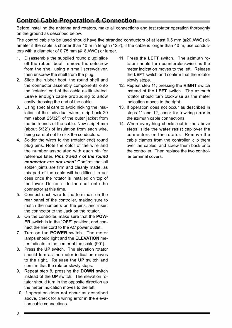
Control Cable Preparation & ConnectionBefore installing the antenna and rotators, make all connections and test rotator operation thoroughly on the ground as described below.The control cable to be used should have five stranded conductors of at least 0.5 mm (#20 AWG) di-ameter if the cable is shorter than 40 m in length (125’); if the cable is longer than 40 m, use conduc-tors with a diameter of 0.75 mm (#18 AWG) or larger.
1. Disassemble the supplied round plug: slide off the rubber boot, remove the setscrew from the shell using a small screwdriver, then unscrew the shell from the plug.
2. Slide the rubber boot, the round shell and the connector assembly components onto the “rotator” end of the cable as illustrated. Leave enough cable protruding to allow easily dressing the end of the cable.
3. Using special care to avoid nicking the insu-lation of the individual wires, strip back 20 mm (about 25/32”) of the outer jacket from the both ends of the cable. Now strip 4 mm (about 5/32”) of insulation from each wire, being careful not to nick the conductors.
4. Solder the wires to the (rotator end) round plug pins. Note the color of the wire and the number associated with each pin for reference later. Pins 6 and 7 of the round connector are not used! Confirm that all solder joints are firm and cleanly made, as this part of the cable will be difficult to ac-cess once the rotator is installed on top of the tower. Do not slide the shell onto the connector at this time.
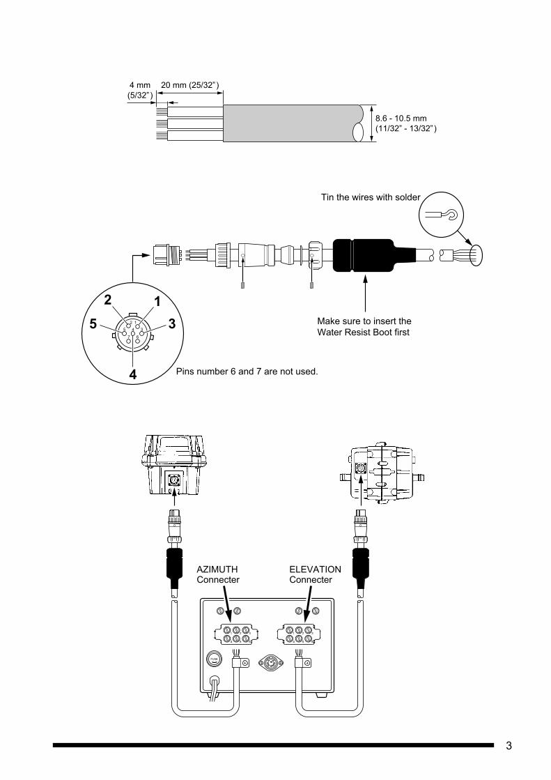
5. Connect each wire to the terminals on the rear panel of the controller, making sure to match the numbers on the pins, and insert the connector to the Jack on the rotator.
6. On the controller, make sure that the POW-ER switch is in the “OFF” position, and con-nect the line cord to the AC power outlet.
7. Turn on the POWER switch. The meter lamps should light and the ELEVATION me-ter indicate to the center of the scale (90°).
8. Press the UP switch. The elevation rotator should turn as the meter indication moves to the right. Release the UP switch and confirm that the rotator slowly stops.
9. Repeat step 8, pressing the DOWN switch instead of the UP switch. The elevation ro-tator should turn in the opposite direction as the meter indication moves to the left.
10. If operation does not occur as described above, check for a wiring error in the eleva-tion cable connections.
11. Press the LEFT switch. The azimuth ro-tator should turn counterclockwise as the meter indication moves to the left. Release the LEFT switch and confirm that the rotator slowly stops.
12. Repeat step 11, pressing the RIGHT switch instead of the LEFT switch. The azimuth rotator should turn clockwise as the meter indication moves to the right.
13. If operation does not occur as described in steps 11 and 12, check for a wiring error in the azimuth cable connections.
14. When everything checks out in the above steps, slide the water resist cap over the connectors on the rotator. Remove the cable clamps from the controller, clip them over the cables, and screw them back onto the controller. Then replace the two control-ler terminal covers.
3
FUSE
ELEVATIONConnecter
AZIMUTHConnecter
Tin the wires with solder
Make sure to insert theWater Resist Boot first
125 3
6
345
12
7
4 Pins number 6 and 7 are not used.
20 mm (25/32”)
8.6 - 10.5 mm(11/32” - 13/32”)
4 mm(5/32”)

4
Pre-Installation AdjustmentSwitch the controller off and adjust the 0. ADJ screws beneath each meter face, if necessary, so that each meter points to the left edge of the scale. Then turn the controller back on for the following steps.
Azimuth IndicatorPress and hold the LEFT switch and allow the azimuth rotator to turn until it reaches its end stop. Note the precise position of the rotator (mark the housing, if necessary), and then press and hold the RIGHT switch to bring the rotator around one full turn to exactly the same position. The meter should now point precise-ly to 360° of the scale. If not, adjust the FULL SCALE ADJ potentiometer at the upper corner of the rear panel above the AZIMUTH terminals.Press the RIGHT switch again to continue clockwise rotation until the rotator reaches its end-stop. The indicator should now point to right edge (90°) of the scale.Elevation IndicatorPress the UP switch to align the 180° markers on the rotator. The meter should now point pre-cisely to 180° at the right end of the scale. If not, adjust the FULL SCALE ADJ potentiome-ter at the upper corner of the rear panel above the ELEVATION terminals.
Notes on Controller Operation: The rotator motors are rated for three-min-
utes intermittent duty. However, they be brought to rest for at least 15 minutes after-wards.
If both UP and DOWN switches or RIGHT and LEFT switches are pressed at the same time, the corresponding rotator turns up or right (clockwise).
Release the switch when the meter indicates in the end zones (the rotator stops).
Remember to turn the controller off when the rotators are not in use.
9045
45
0
0
135
180
DOWNDOWN UP POWER
90
90
S
N
EW
N
E
0
270180360
AZIMUTHELEVATION
G-5500ELEVATION - AZIMUTH DUAL CONTROLLER
RIGHT(CW)
LEFT(CCW)
AzimuthFULL SCALE ADJ.
POWERSwitch
RIGHTSwitch
LEFTSwitch
UPSwitch
DOWNSwitch
ElevationFULL SCALE ADJ.
FUSE

5
External ControlIF the optional GS-232 Computer Control Inter-faces Unit is installed, the RS-232C cable from the computer routes through this grommet, and is affixed in place by the nylon cable clamp.
Pin Function
1 Provides 2 to 4.5 VDC corresponding to 0 ° to 180 °
2 Connect to Pin 8 to rotate right (clockwise)3 Connect to Pin 8 to rotate up4 Connect to Pin 8 to rotate left (counterclockwise)5 Connect to Pin 8 to rotate down
6 Provides 2 to 4.5 VDC corresponding to 0 ° to 450 °
7 Provides DC 13 V to 8 V at up to 100 mA8 Common ground
FUSE
External Control
13
8
24
7 6
5
Soldering
8-pin DIN Plug Assy
Rotator InstallationThe maximum safe load of the G-5500DC depends on the physical size of the antenna, method and quality of mechanical installation, and maximum wind velocity at the installation site.Notice that the preferred mounting method re-quires that each antenna be attached to the boom at its center of gravity, with the boom then attached to the elevation rotator at its center of gravity. This minimizes stress on the rota-tor and supporting structure, especially during strong winds.The azimuth rotator may be mounted at the top of the mast together with the elevation rotator, or separately inside of a supporting tower. The latter method is generally stronger, and prefera-ble in high wind locations or for large antennas, but requires some additional hardware not sup-plied with the G-5500DC kits.Mounting the Rotators TogetherNOTE: If the elevation rotator is to be mounted on the mast alone, skip this section and see “Mounting the Rotators Separately”.1. Bolt the U-bracket to
the top of the azimuth rotator using four M8x16 bolts, spring washers and flat washers.
2. nsert the elevation ro-tator into the U-bracket, then fasten the elevation rotator using four M8x25 bolts, spring washers and flat washers.

6
Mounting the Rotators SeparatelyOnly do this if the elevation rotator is to be mounted alone on the mast. You will need four long stud bolts S8002738 and four additional pipe clamps S8003012 (available from your dealer).1. Slip an 8 mm spring washer over the short-
thread end of each stud bolt (x4), and screw the stud bolts firmly into holes in the side of the elevation rotator.
2. Slip an 8 mm flat washer over each installed stud bolt, and then the pipe clamps. Place another flat washer and then a spring wash-er over the end of each stud bolt, and start a nut on each to hold the hardware in place.
Installing the boom in the Elevation Rotator.
Do these steps for all installations.1. Slide the boom through the rotator.2. Place one U-bolt over each arm of the rota-
tor, and assemble one pipe clamp, flat wash-ers, spring washers and nuts on the U-bolts. Center the boom carefully, and alternately tighten the nuts on each U-bolt ½-turn be-yond the point where the spring washers are flattened.
Be sure to leave enough slack in both the eleva-tion control cable and the coaxial cable feedline around the azimuth rotator so the antenna can rotate 450° without straining the cable or feed-line.For dual parallel arrays, feedlines should be taped to the boom on either side of the rotator, with enough slack left to allow 180° rotation without stressing the feedlines.
No. Description Qty.À 8 Ø Spring Washer 8Á 8 Ø Nut 8Â 8 Ø Washer 8Ã 8 Ø Stud Bolt 4Ä Boom/Mast Clamp 6Å U Bolt 2Æ 6 Ø Washer 4Ç 6 Ø Spring Washer 4È 6 Ø Nut 4
7
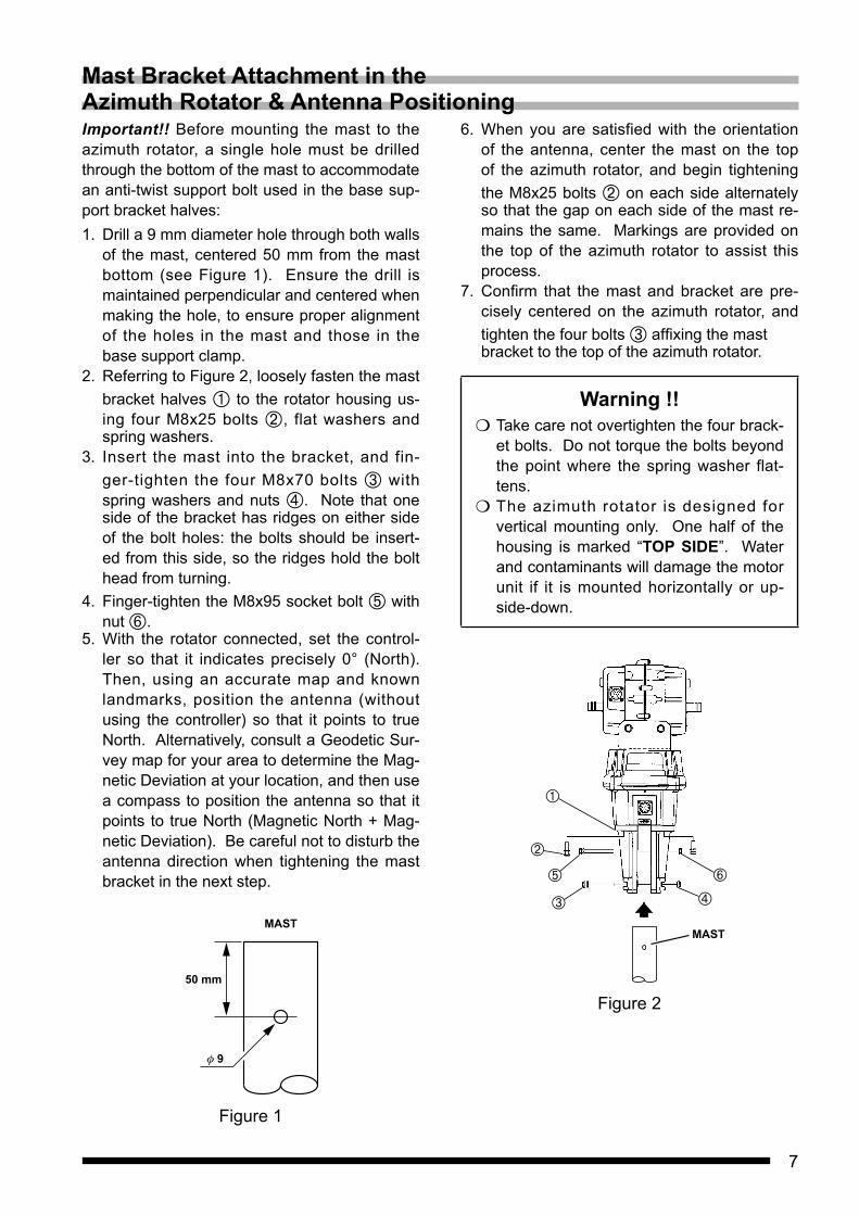
Important!! Before mounting the mast to the azimuth rotator, a single hole must be drilled through the bottom of the mast to accommodate an anti-twist support bolt used in the base sup-port bracket halves:1. Drill a 9 mm diameter hole through both walls
of the mast, centered 50 mm from the mast bottom (see Figure 1). Ensure the drill is maintained perpendicular and centered when making the hole, to ensure proper alignment of the holes in the mast and those in the base support clamp.
2. Referring to Figure 2, loosely fasten the mast bracket halves À to the rotator housing us-ing four M8x25 bolts Á, flat washers and spring washers.
3. Insert the mast into the bracket, and fin-ger-tighten the four M8x70 bolts  with spring washers and nuts Ã. Note that one side of the bracket has ridges on either side of the bolt holes: the bolts should be insert-ed from this side, so the ridges hold the bolt head from turning.
4. Finger-tighten the M8x95 socket bolt Ä with nut Å.
5. With the rotator connected, set the control-ler so that it indicates precisely 0° (North). Then, using an accurate map and known landmarks, position the antenna (without using the controller) so that it points to true North. Alternatively, consult a Geodetic Sur-vey map for your area to determine the Mag-netic Deviation at your location, and then use a compass to position the antenna so that it points to true North (Magnetic North + Mag-netic Deviation). Be careful not to disturb the antenna direction when tightening the mast bracket in the next step.
MAST
50 mm
9
Figure 1
6. When you are satisfied with the orientation of the antenna, center the mast on the top of the azimuth rotator, and begin tightening the M8x25 bolts Á on each side alternately so that the gap on each side of the mast re-mains the same. Markings are provided on the top of the azimuth rotator to assist this process.
7. Confirm that the mast and bracket are pre-cisely centered on the azimuth rotator, and tighten the four bolts  affixing the mast bracket to the top of the azimuth rotator.
Warning !! Take care not overtighten the four brack-
et bolts. Do not torque the bolts beyond the point where the spring washer flat-tens.
The azimuth rotator is designed for vertical mounting only. One half of the housing is marked “TOP SIDE”. Water and contaminants will damage the motor unit if it is mounted horizontally or up-side-down.
MAST
Figure 2
Mast Bracket Attachment in the Azimuth Rotator & Antenna Positioning

8
TroubleshootingIf a malfunction is suspected, check the following items before requesting a repair.
Rotor does not rotaten Is the cable and connector correctly con-
nected?n Are the same pin numbers connected be-
tween the connector of the rotor and the terminal on the rear of the controller?
n Is the fuse blown out?Measure the voltage between the terminals on the back of the controller (see the table below), and if there is no voltage, the fuse inside the controller may be burned out.If the fuse is blown, find the cause (short circuit between the terminals on the back of the controller, etc.) and make corrections before replacing the 3A fuse on the board inside the controller.CAUTION! Only replace with a fuse of
similar type and rating (3A).* To measure voltage between terminals, re-
move the connection cable to the rotor and the cable connected to the external control terminal.
Switch Terminal Pin VoltagePower switch is in the "ON" position.
AZIMUTH 1 - 3 DC 6VELEVATION 1 - 3Press the LEFT switch. AZIMUTH 4 - 5
DC 23VPress the RIGHT switch.Press the DOWN switch. ELEVATION 4 - 5Press the UP switch.
The controller does not turn on.n Is the fuse blown out?
Replace the 2A fuse in the fuse holder on the back of the controller after finding the cause and making corrections.CAUTION! Only replace with a similar
type and rating 2A fuse for 117 V AC operation, or 1A for 220 V AC.
FUSEFuse holder

Disposal of Electronic and Electrical EquipmentProducts with the symbol (crossed-out wheeled bin) cannot be disposed as household waste.Electronic and Electrical Equipment should be recycled at a facility capable of handling these items and their waste by-products.Please contact a local equipment supplier representative or service center for information about the waste collection system in your country.
YAESU LIMITED WARRANTYLimited Warranty is valid only in the country/region where this product was originally purchased.On-line Warranty Registration:Thank you for buying YAESU products! We are confident your new radio will serve your needs for many years! Please register your product at www.yaesu.com - Owner’s CornerWarranty Terms:Subject to the Limitations of the Warranty and the Warranty Procedures described below, YAESU MUSEN hereby warrants this product to be free of defects in materials and workmanship in normal use during the “Warranty Period.” (the “Limited Warranty”).Limitations of Warranty:A. YAESU MUSEN is not liable for any express warranties except the Limited Warranty described above.B. The Limited Warranty is extended only to the original end-use purchaser or the person receiving this product as a gift, and
shall not be extended to any other person or transferee.C. Unless a different warranty period is stated with this YAESU product, the Warranty Period is three years from the date of
retail purchase by the original end-use purchaser.D. The Limited Warranty is valid only in the country/region where this product was originally purchased.E. During the Warranty Period, YAESU MUSEN will, at its sole option, repair or replace (using new or refurbished replacement
parts) any defective parts within a reasonable period of time and free of charge.F. The Limited Warranty does not cover shipping cost (including transportation and insurance) from you to us, or any import
fees, duties or taxes.G. The Limited Warranty does not cover any impairment caused by tampering, misuse, failure to follow instructions supplied
with the product, unauthorized modifications, or damage to this product for any reasons, such as: accident; excess moisture; lightning; power surges; connection to improper voltage supply; damage caused by inadequate packing or shipping procedures; loss of, damage to or corruption of stored data; product modification to enable operation in another country/purpose other than the country/purpose for which it was designed, manufactured, approved and/or authorized; or the repair of products damaged by these modifications.
H. The Limited Warranty applies only to the product as it existed at the time of the original purchase, by the original retail purchaser, and shall not preclude YAESU MUSEN from later making any changes in design, adding to, or otherwise improving subsequent versions of this product, or impose upon YAESU MUSEN any obligation to modify or alter this product to conform to such changes, or improvements.
I. YAESU MUSEN assumes no responsibility for any consequential damages caused by, or arising out of, any such defect in materials or workmanship.
J. TO THE FULLEST EXTENT PERMITTED BY LAW, YAESU MUSEN SHALL NOT BE RESPONSIBLE FOR ANY IMPLIED WARRANTY WITH RESPECT TO THIS PRODUCT.
K. If the original retail purchaser timely complies with the Warranty Procedures described below, and YAESU MUSEN elects to send the purchaser a replacement product rather than repair the “original product”, then the Limited Warranty shall apply to the replacement product only for the remainder of the original product Warranty Period.
L. Warranty statutes vary from state to state, or country to country, so some of the above limitations may not apply to your location.
Warranty Procedures:1. To find the Authorized YAESU Service Center in your country/region, visit www.yaesu.com. Contact the YAESU Service
Center for specific return and shipping instructions, or contact an authorized YAESU dealer/distributor from whom the product was originally purchased.
2. Include proof of original purchase from an authorized YAESU dealer/distributor, and ship the product, freight prepaid, to the address provided by the YAESU Service Center in your country/ region.
3. Upon receipt of this product, returned in accordance with the procedures described above, by the YAESU Authorized Service Center, all reasonable efforts will be expended by YAESU MUSEN to cause this product to conform to its original specifications. YAESU MUSEN will return the repaired product (or a replacement product) free of charge to the original purchaser. The decision to repair or replace this product is the sole discretion of YAESU MUSEN.
Other conditions:YAESU MUSEN’S MAXIMUM LIABILITY SHALL NOT EXCEED THE ACTUAL PURCHASE PRICE PAID FOR THE PRODUCT. IN NO EVENT SHALL YAESU MUSEN BE LIABLE FOR LOSS OF, DAMAGE TO OR CORRUPTION OF STORED DATA, OR FOR SPECIAL, INCIDENTAL, CONSEQUENTIAL, OR INDIRECT DAMAGES, HOW EVER CAUSED; INCLUDING WITHOUT LIMITATION TO THE REPLACEMENT OF EQUIPMENT AND PROPERTY, AND ANY COSTS OF RECOVERING, PROGRAMMING OR REPRODUCING ANY PROGRAM OR DATA STORED IN OR USED WITH THE YAESU PRODUCT.Some Countries in Europe and some States of the USA do not allow the exclusion or limitation of incidental or consequential damages, or a limitation on how long an implied warranty lasts, so the above limitation or exclusions may not apply. This warranty provides specific rights, there may be other rights available which may vary between countries in Europe or from state to state within the USA.This Limited Warranty is void if the label bearing the serial number has been removed or defaced.

Printed in Japan
Copyright 2019YAESU MUSEN CO., LTD.All rights reserved.No portion of this manual may bereproduced without the permission ofYAESU MUSEN CO., LTD.
YAESU MUSEN CO., LTD.Tennozu Parkside Building2-5-8 Higashi-Shinagawa, Shinagawa-ku, Tokyo 140-0002 JapanYAESU USA6125 Phyllis Drive, Cypress, CA 90630, U.S.A.YAESU UKUnit 12, Sun Valley Business Park, Winnall CloseWinchester, Hampshire, SO23 0LB, U.K.
1906V-BS