Embed Size (px)
Citation preview
G-450ADCG-450CDC
Antenna Rotator & ControllerUser Manual
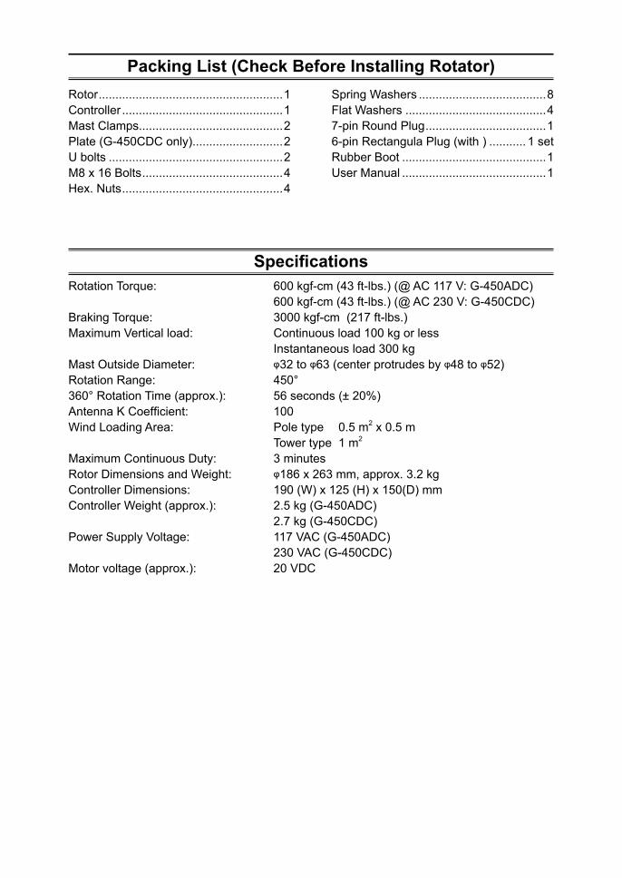
Packing List (Check Before Installing Rotator)Rotor .......................................................1Controller ................................................1Mast Clamps...........................................2Plate (G-450CDC only)...........................2U bolts ....................................................2M8 x 16 Bolts ..........................................4Hex. Nuts ................................................4
Spring Washers ......................................8Flat Washers ..........................................47-pin Round Plug ....................................16-pin Rectangula Plug (with ) ........... 1 setRubber Boot ...........................................1User Manual ...........................................1
SpecificationsRotation Torque: 600 kgf-cm (43 ft-lbs.) (@ AC 117 V: G-450ADC) 600 kgf-cm (43 ft-lbs.) (@ AC 230 V: G-450CDC)Braking Torque: 3000 kgf-cm (217 ft-lbs.)Maximum Vertical load: Continuous load 100 kg or less Instantaneous load 300 kgMast Outside Diameter: φ32 to φ63 (center protrudes by φ48 to φ52)Rotation Range: 450°360° Rotation Time (approx.): 56 seconds (± 20%)Antenna K Coefficient: 100Wind Loading Area: Pole type 0.5 m2 x 0.5 m Tower type 1 m2
Maximum Continuous Duty: 3 minutesRotor Dimensions and Weight: φ186 x 263 mm, approx. 3.2 kgController Dimensions: 190 (W) x 125 (H) x 150(D) mmController Weight (approx.): 2.5 kg (G-450ADC) 2.7 kg (G-450CDC)Power Supply Voltage: 117 VAC (G-450ADC) 230 VAC (G-450CDC)Motor voltage (approx.): 20 VDC
1
Installation/Operation Precautions• Always use (Metric) M8x16 bolts when mounting the rotor to the tower or roof tripod
mounting plate.• Take care not to scratch the surface of the rotator or its mounting hardware. If the protec-
tive coating is scratched, the underlying metal may be subject to corrosion or rusting.• During operation, do not suddenly reverse the rotation during operation, as this places a
large load on the internal components of the rotor. Let the antenna come to a complete stop before reversing the direction of rotation.
• Do not engage the rotor for more than three minutes of continuous rotation. While this ro-tor can operate for up to 3 minutes continuously, operation must thereafter be halted, and the motor must be allowed to cool for at least 15 minutes afterwards.
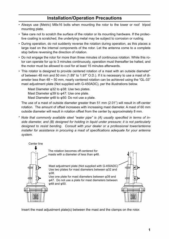
• This rotator is designed to provide centered rotation of a mast with an outside diameter* of between 48 mm and 50 mm (1.89” to 1.97” O.D.). If it is necessary to use a mast of di-ameter less than 48 ~ 50 mm, nearly centered rotation can be achieved using the “GL-33” mast adjustment plate (Not supplied with G-450ADC), per the illustrations below.
Mast Diameter φ32 to φ38: Use two plates.Mast Diameter φ39 to φ47: Use one plate.Mast Diameter φ48 to φ50: Do not use a plate.
The use of a mast of outside diameter greater than 51 mm (2.01”) will result in off-center rotation. The amount of offset increases with increasing mast diameter. A mast of 60 mm outside diameter will result in rotation offset from the center by approximately 8 mm.
* Note that commonly available steel “water pipe” is (A) usually specified in terms of in-side diameter, and (B) designed for holding in liquid under pressure; it is not particularly designed to resist bending. Consult with your dealer or a professional tower/antenna installer for assistance in procuring a mast of specifications adequate for your antenna system.
Center line
The rotation becomes off-centered for masts with a diameter of less than φ48.
Mast adjustment plate (Not supplied with G-450ADC) Use two plates for mast diameters between φ32 and φ38.Use one plate for mast diameters between φ39 and φ47. Do not use a plate for mast diameters between φ48 and φ50.
Insert the mast adjustment plate(s) between the mast and the clamps on the rotor.
2
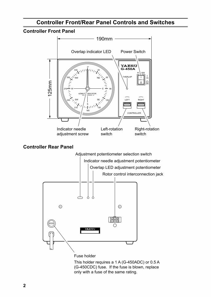
Controller Front/Rear Panel Controls and SwitchesController Front Panel
W
S
SE
NE
SW
AZIMUTH INDICATOREACH DIVISION 5ー
NW
E270
300
240
330
210180
0°
90
60
120
30
150
G-450A
OFF
ON
LEFT RIGHT
OVERLAP
CONTROLLER
POWER
190mm
Overlap indicator LED
Indicator needleadjustment screw
Left-rotationswitch
Right-rotationswitch
Power Switch12
5mm
Controller Rear PanelAdjustment potentiometer selection switch
Indicator needle adjustment potentiometerOverlap LED adjustment potentiometer
Rotor control interconnection jack
Fuse holderThis holder requires a 1 A (G-450ADC) or 0.5 A (G-450CDC) fuse. If the fuse is blown, replace only with a fuse of the same rating.
3
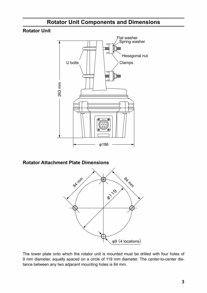
Rotator Unit Components and DimensionsRotator Unit
263
mm
φ186
ClampsU bolts
Spring washerFlat washer
Hexagonal nut
Rotator Attachment Plate Dimensions
84 mm84 m
m
φ119
φ9 (4 locations)
The tower plate onto which the rotator unit is mounted must be drilled with four holes of 9 mm diameter, equally spaced on a circle of 119 mm diameter. The center-to-center dis-tance between any two adjacent mounting holes is 84 mm.
4
Rotator Unit Components and DimensionsThe size and type of antenna(s) that can be attached to this rotator will differ widely, de-pending on the installation method, local terrain, and the maximum expected wind speeds at your location. The following pages describe typical antennas which are acceptable for installation with the G-450ADC/-450CDC. The discussion below assumes maximum wind speeds of 30 meters per second (67 mph/108kph), and it is recommended that you include a safety margin of at least 30 % to account for higher wind gusts or other factors which might potentially cause damage to your installation.
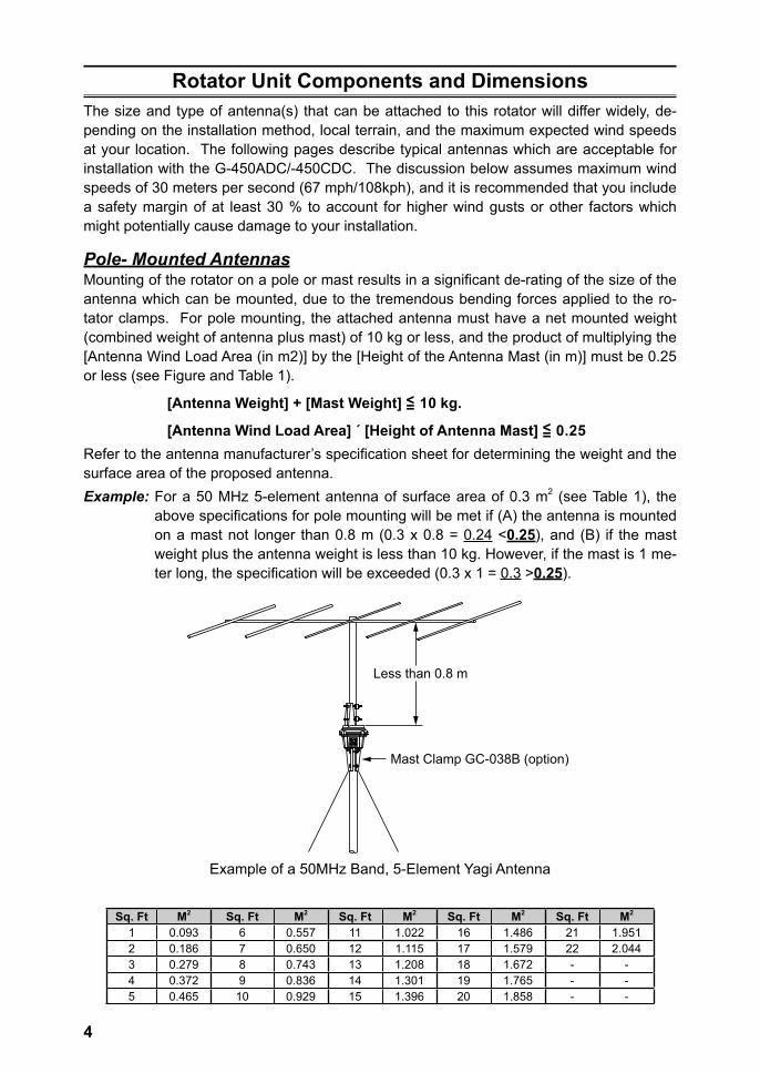
Pole- Mounted AntennasMounting of the rotator on a pole or mast results in a significant de-rating of the size of the antenna which can be mounted, due to the tremendous bending forces applied to the ro-tator clamps. For pole mounting, the attached antenna must have a net mounted weight (combined weight of antenna plus mast) of 10 kg or less, and the product of multiplying the [Antenna Wind Load Area (in m2)] by the [Height of the Antenna Mast (in m)] must be 0.25 or less (see Figure and Table 1).
[Antenna Weight] + [Mast Weight] <= 10 kg.
[Antenna Wind Load Area] ´ [Height of Antenna Mast] <= 0.25Refer to the antenna manufacturer’s specification sheet for determining the weight and the surface area of the proposed antenna.Example: For a 50 MHz 5-element antenna of surface area of 0.3 m2 (see Table 1), the
above specifications for pole mounting will be met if (A) the antenna is mounted on a mast not longer than 0.8 m (0.3 x 0.8 = 0.24 <0.25), and (B) if the mast weight plus the antenna weight is less than 10 kg. However, if the mast is 1 me-ter long, the specification will be exceeded (0.3 x 1 = 0.3 >0.25).
Less than 0.8 m
Mast Clamp GC-038B (option)
Example of a 50MHz Band, 5-Element Yagi Antenna
Sq. Ft M2 Sq. Ft M2 Sq. Ft M2 Sq. Ft M2 Sq. Ft M2
1 0.093 6 0.557 11 1.022 16 1.486 21 1.9512 0.186 7 0.650 12 1.115 17 1.579 22 2.0443 0.279 8 0.743 13 1.208 18 1.672 - -4 0.372 9 0.836 14 1.301 19 1.765 - -5 0.465 10 0.929 15 1.396 20 1.858 - -
5
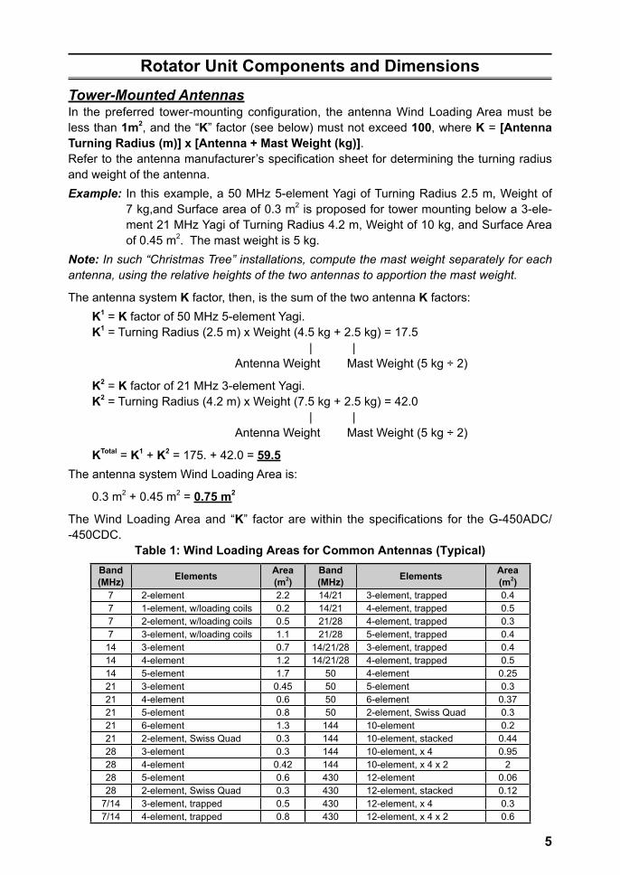
Rotator Unit Components and DimensionsTower-Mounted AntennasIn the preferred tower-mounting configuration, the antenna Wind Loading Area must be less than 1m2, and the “K” factor (see below) must not exceed 100, where K = [Antenna Turning Radius (m)] x [Antenna + Mast Weight (kg)].Refer to the antenna manufacturer’s specification sheet for determining the turning radius and weight of the antenna.Example: In this example, a 50 MHz 5-element Yagi of Turning Radius 2.5 m, Weight of
7 kg,and Surface area of 0.3 m2 is proposed for tower mounting below a 3-ele-ment 21 MHz Yagi of Turning Radius 4.2 m, Weight of 10 kg, and Surface Area of 0.45 m2. The mast weight is 5 kg.
Note: In such “Christmas Tree” installations, compute the mast weight separately for each antenna, using the relative heights of the two antennas to apportion the mast weight.
The antenna system K factor, then, is the sum of the two antenna K factors:K1 = K factor of 50 MHz 5-element Yagi.K1 = Turning Radius (2.5 m) x Weight (4.5 kg + 2.5 kg) = 17.5 | | Antenna Weight Mast Weight (5 kg ÷ 2)
K2 = K factor of 21 MHz 3-element Yagi.K2 = Turning Radius (4.2 m) x Weight (7.5 kg + 2.5 kg) = 42.0 | | Antenna Weight Mast Weight (5 kg ÷ 2)
KTotal = K1 + K2 = 175. + 42.0 = 59.5The antenna system Wind Loading Area is:
0.3 m2 + 0.45 m2 = 0.75 m2
The Wind Loading Area and “K” factor are within the specifications for the G-450ADC/ -450CDC.
Table 1: Wind Loading Areas for Common Antennas (Typical)Band(MHz) Elements Area
(m2)Band(MHz) Elements Area
(m2)7 2-element 2.2 14/21 3-element, trapped 0.47 1-element, w/loading coils 0.2 14/21 4-element, trapped 0.57 2-element, w/loading coils 0.5 21/28 4-element, trapped 0.37 3-element, w/loading coils 1.1 21/28 5-element, trapped 0.414 3-element 0.7 14/21/28 3-element, trapped 0.414 4-element 1.2 14/21/28 4-element, trapped 0.514 5-element 1.7 50 4-element 0.2521 3-element 0.45 50 5-element 0.321 4-element 0.6 50 6-element 0.3721 5-element 0.8 50 2-element, Swiss Quad 0.321 6-element 1.3 144 10-element 0.221 2-element, Swiss Quad 0.3 144 10-element, stacked 0.4428 3-element 0.3 144 10-element, x 4 0.9528 4-element 0.42 144 10-element, x 4 x 2 228 5-element 0.6 430 12-element 0.0628 2-element, Swiss Quad 0.3 430 12-element, stacked 0.12
7/14 3-element, trapped 0.5 430 12-element, x 4 0.37/14 4-element, trapped 0.8 430 12-element, x 4 x 2 0.6
6
Control Cable InstallationBefore installing the rotator, mast, and antenna, prepare the rotator control cable and test rotator system performance on the ground. Potential alignment, cabling, or other problems can quickly be resolved on the ground; once a rotator is mounted, however, troubleshoot-ing may require that the tower be climbed and/or the rotator be removed and lowered to the ground!
Control Cable PreparationThe control cable to be used should have six stranded conductors of at least 0.5 mm (#20 AWG) diameter if the cable is shorter than 40 m in length (125’); if the cable is longer than 40 m, use conductors with a diameter of 0.75 mm (#18 AWG) or larger.
The optional control cable “C-25MWP (25 m)” or “C-40MWP (40 m)”, are recommended to connect the controller and the rotator.Although C-25MWP and C-40MWP are 6 core cables, only 4 cores are used with the G-450ADC/-450CDC.
1. Disassemble the supplied round plug: slide off the rubber boot, remove the setscrew from the shell using a small screwdriver, then unscrew the shell from the plug. Save the setscrew in a safe place until step 10, so you don’t lose it.
2. Slide the rubber boot and the round shell over the “rotator” end of the cable. Leave enough cable protruding to allow easy dressing the end of the cable.
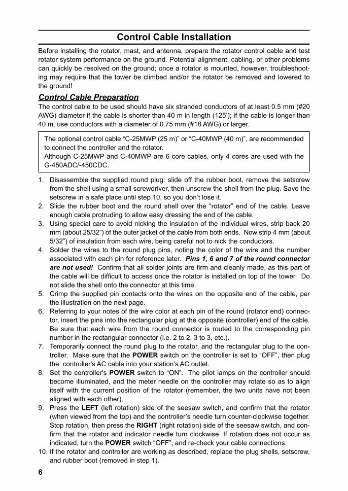
3. Using special care to avoid nicking the insulation of the individual wires, strip back 20 mm (about 25/32”) of the outer jacket of the cable from both ends. Now strip 4 mm (about 5/32”) of insulation from each wire, being careful not to nick the conductors.
4. Solder the wires to the round plug pins, noting the color of the wire and the number associated with each pin for reference later. Pins 1, 6 and 7 of the round connector are not used! Confirm that all solder joints are firm and cleanly made, as this part of the cable will be difficult to access once the rotator is installed on top of the tower. Do not slide the shell onto the connector at this time.
5. Crimp the supplied pin contacts onto the wires on the opposite end of the cable, per the illustration on the next page.
6. Referring to your notes of the wire color at each pin of the round (rotator end) connec-tor, insert the pins into the rectangular plug at the opposite (controller) end of the cable. Be sure that each wire from the round connector is routed to the corresponding pin number in the rectangular connector (i.e. 2 to 2, 3 to 3, etc.).
7. Temporarily connect the round plug to the rotator, and the rectangular plug to the con-troller. Make sure that the POWER switch on the controller is set to “OFF”, then plug the controller's AC cable into your station’s AC outlet.
8. Set the controller's POWER switch to “ON”. The pilot lamps on the controller should become illuminated, and the meter needle on the controller may rotate so as to align itself with the current position of the rotator (remember, the two units have not been aligned with each other).
9. Press the LEFT (left rotation) side of the seesaw switch, and confirm that the rotator (when viewed from the top) and the controller’s needle turn counter-clockwise together. Stop rotation, then press the RIGHT (right rotation) side of the seesaw switch, and con-firm that the rotator and indicator needle turn clockwise. If rotation does not occur as indicated, turn the POWER switch “OFF”, and re-check your cable connections.
10. If the rotator and controller are working as described, replace the plug shells, setscrew, and rubber boot (removed in step 1).
7
20 mm
8.6 ~ 10.5 mm
4 mm
Crimp with crimping tool or a pair of pliers
Insert to the fullest extent
Assembly of 6-pin Plastic Connector
Tin the wires with solder
Make sure to insert theWater Resist Boot first
25 3
6
345
12
7
4 Terminal 1, 6 and 7 are not used.
Assembly of 7-pin Metal Connector
Pin # 1 and 7 of the seven pin metal connector is not used.
(as viewed from pin insertion side) (as viewed from solder side)
Wiring for the control cable (identical numbers to be connected)
8
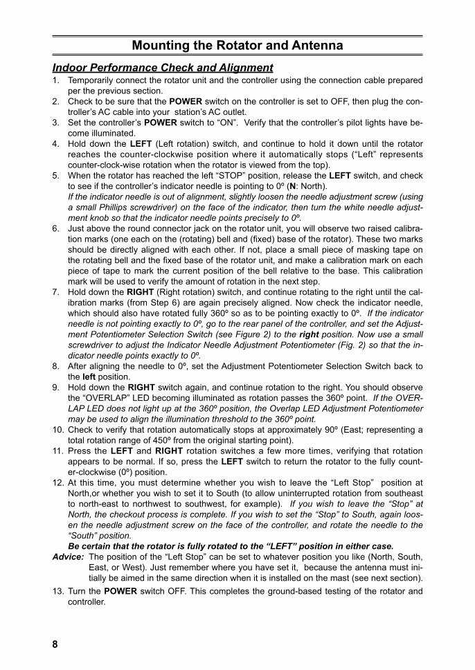
Mounting the Rotator and AntennaIndoor Performance Check and Alignment1. Temporarily connect the rotator unit and the controller using the connection cable prepared
per the previous section.2. Check to be sure that the POWER switch on the controller is set to OFF, then plug the con-
troller’s AC cable into your station’s AC outlet.3. Set the controller’s POWER switch to “ON”. Verify that the controller’s pilot lights have be-
come illuminated.4. Hold down the LEFT (Left rotation) switch, and continue to hold it down until the rotator
reaches the counter-clockwise position where it automatically stops (“Left” represents counter-clock-wise rotation when the rotator is viewed from the top).
5. When the rotator has reached the left “STOP” position, release the LEFT switch, and check to see if the controller’s indicator needle is pointing to 0º (N: North).
If the indicator needle is out of alignment, slightly loosen the needle adjustment screw (using a small Phillips screwdriver) on the face of the indicator, then turn the white needle adjust-ment knob so that the indicator needle points precisely to 0º.
6. Just above the round connector jack on the rotator unit, you will observe two raised calibra-tion marks (one each on the (rotating) bell and (fixed) base of the rotator). These two marks should be directly aligned with each other. If not, place a small piece of masking tape on the rotating bell and the fixed base of the rotator unit, and make a calibration mark on each piece of tape to mark the current position of the bell relative to the base. This calibration mark will be used to verify the amount of rotation in the next step.
7. Hold down the RIGHT (Right rotation) switch, and continue rotating to the right until the cal-ibration marks (from Step 6) are again precisely aligned. Now check the indicator needle, which should also have rotated fully 360º so as to be pointing exactly to 0º. If the indicator needle is not pointing exactly to 0º, go to the rear panel of the controller, and set the Adjust-ment Potentiometer Selection Switch (see Figure 2) to the right position. Now use a small screwdriver to adjust the Indicator Needle Adjustment Potentiometer (Fig. 2) so that the in-dicator needle points exactly to 0º.
8. After aligning the needle to 0º, set the Adjustment Potentiometer Selection Switch back to the left position.
9. Hold down the RIGHT switch again, and continue rotation to the right. You should observe the “OVERLAP” LED becoming illuminated as rotation passes the 360º point. If the OVER-LAP LED does not light up at the 360º position, the Overlap LED Adjustment Potentiometer may be used to align the illumination threshold to the 360º point.
10. Check to verify that rotation automatically stops at approximately 90º (East; representing a total rotation range of 450º from the original starting point).
11. Press the LEFT and RIGHT rotation switches a few more times, verifying that rotation appears to be normal. If so, press the LEFT switch to return the rotator to the fully count-er-clockwise (0º) position.
12. At this time, you must determine whether you wish to leave the “Left Stop” position at North,or whether you wish to set it to South (to allow uninterrupted rotation from southeast to north-east to northwest to southwest, for example). If you wish to leave the “Stop” at North, the checkout process is complete. If you wish to set the “Stop” to South, again loos-en the needle adjustment screw on the face of the controller, and rotate the needle to the “South” position.
Be certain that the rotator is fully rotated to the “LEFT” position in either case.Advice: The position of the “Left Stop” can be set to whatever position you like (North, South,
East, or West). Just remember where you have set it, because the antenna must ini-tially be aimed in the same direction when it is installed on the mast (see next section).
13. Turn the POWER switch OFF. This completes the ground-based testing of the rotator and controller.
9
Mounting the Rotator and Antenna
W
S
SE
NE
SW
AZIMUTH INDICATOREACH DIVISION 5ー
NW
E270
300
240
330
210180
0°
90
60
120
30
150
G-450A
OFF
ON
LEFT RIGHT
OVERLAP
CONTROLLER
POWER
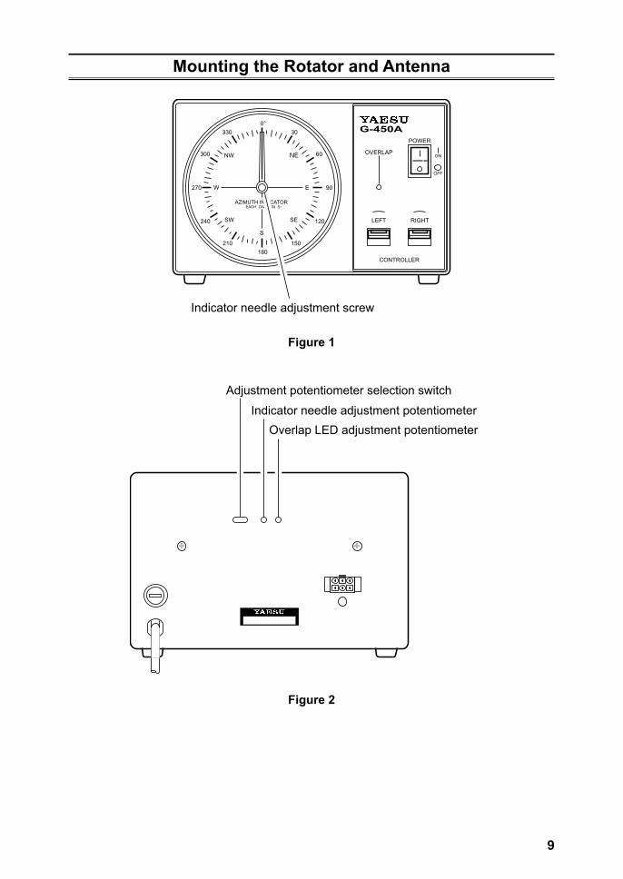
Indicator needle adjustment screw
Figure 1
Adjustment potentiometer selection switch
Indicator needle adjustment potentiometerOverlap LED adjustment potentiometer
Figure 2
10
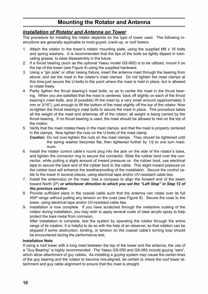
Mounting the Rotator and AntennaInstallation of Rotator and Antenna on TowerThe procedure for installing the rotator depends on the type of tower used. The following in-structions are generally applicable to most guyed, crank-up, or roof towers.
1. Attach the rotator to the tower’s rotator mounting plate, using the supplied M8 x 16 bolts and spring washers. It is recommended that the tips of the bolts be lightly dipped in lubri-cating grease, to ease disassembly in the future.
2. If a thrust bearing (such as the optional Yaesu model GS-065) is to be utilized, mount it on the top of the tower (see Figure 4) using the supplied hardware.
3. Using a “gin pole” or other raising fixture, insert the antenna mast through the bearing from above, and set the mast in the rotator’s mast clamps. Do not tighten the mast clamps at this time;just secure the U-bolts to the point where the mast is held in place, but is allowed to rotate freely.
4. Partly tighten the thrust bearing’s mast bolts, so as to center the mast in the thrust bear-ing. When you are satisfied that the mast is centered, back off slightly on each of the thrust bearing’s mast bolts, and (if possible) lift the mast by a very small amount (approximately 5 mm or 3/16”), just enough to lift the bottom of the mast slightly off the top of the rotator. Now re-tighten the thrust bearing’s mast bolts to secure the mast in place. This procedure takes all the weight of the mast and antennas off of the rotator; all weight is being carried by the thrust bearing. If no thrust bearing is used, the mast should be allowed to rest on the top of the rotator.
5. Verify that the mast rotates freely in the mast clamps, and that the mast is properly centered in the clamps. Now tighten the nuts on the U-bolts of the mast clamp.Caution: Do not over-tighten the nuts on the mast clamps. They should be tightened until
the spring washer becomes flat, then tightened further by 1/2 to one turn maxi-mum.
6. Install the rotator control cable’s round plug into the jack on the side of the rotator’s base, and tighten the connector ring to secure the connector. Slide the rubber boot over the con-nector; while putting a slight amount of inward pressure on the rubber boot, use electrical tape to secure the back end of the rubber boot to the cable. This slight inward pressure on the rubber boot will enhance the weatherproofing of the installation. Secure the control ca-ble to the tower in several places, using electrical tape and/or UV-resistant cable ties.
7. Install the antenna(s) on the mast. Use a compass to align the forward end of the beam toward North (0º) or whichever direction to which you set the “Left Stop” in Step 12 of the previous section.
8. Provide sufficient slack in the coaxial cable such that the antenna can rotate over its full 450º range without putting any tension on the coax (see Figure 8). Secure the coax to the tower, using electrical tape and/or UV-resistant cable ties.
9. Installation is now complete. If you have scratched through the melamine coating of the rotator during installation, you may wish to apply several coats of clear acrylic spray to help protect the bare metal from corrosion.
After installation is complete, test the system by operating the rotator through the entire range of its rotation. It is helpful to do so with the help of an observer, so that rotation can be stopped if some obstruction, binding, or tension on the coaxial cable’s turning loop should be encountered during the performance test.
Installation NoteIf using a roof tower with a long mast between the top of the tower and the antenna, the use of a “Guy Bearing” is highly recommended. The Yaesu GS-050 and GS-065 include guying “ears”, which allow attachment of guy cables. As installing a guying system may cause the center-lines of the guy bearing and the rotator to become mis-aligned, be certain to check the roof tower at-tachment and guy cable alignment to ensure that the mast is straight.
11
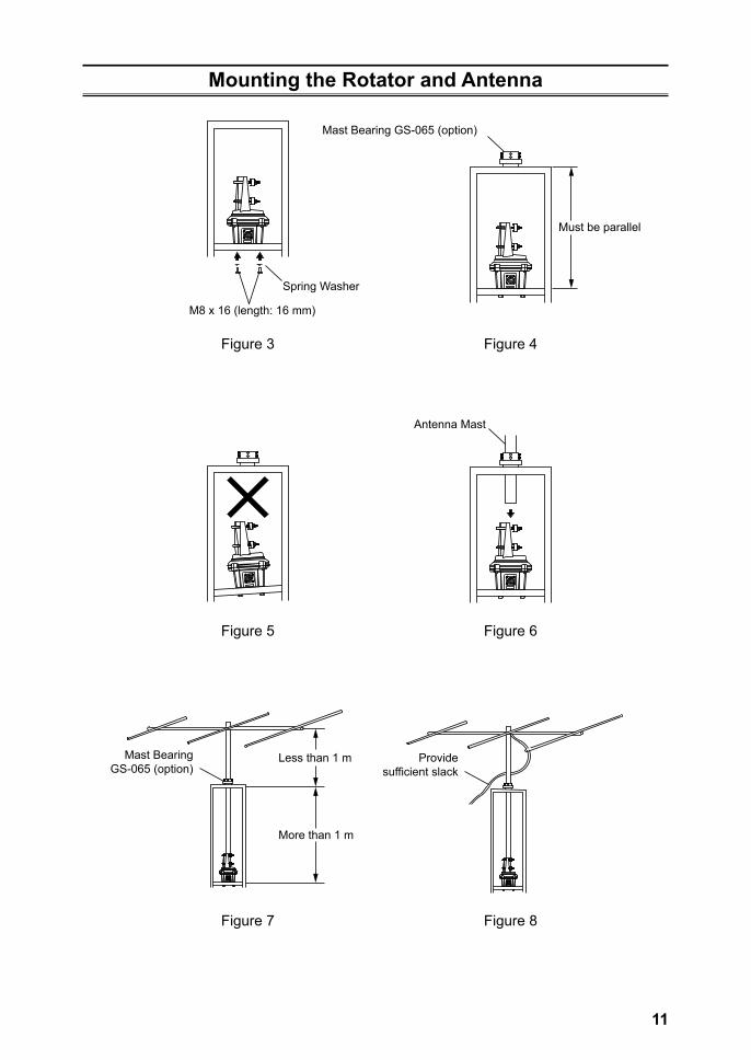
Mounting the Rotator and Antenna
Spring Washer
Antenna Mast
Mast Bearing GS-065 (option)
Mast BearingGS-065 (option)
Must be parallel
M8 x 16 (length: 16 mm)
Figure 3 Figure 4
Figure 5 Figure 6
Figure 7 Figure 8
Provide sufficient slack
More than 1 m
Less than 1 m
12
Important!The installation of a rotatable antenna on a tower system is a dangerous and potentially life-threatening task, if due care is not taken.
A tower must never be installed in a position where it could fall across power distribution cables in the event of a catastrophic tower failure during a windstorm or earthquake.
The control cable attached to this rotator could, in the event of a nearby or direct light-ning strike, carry lethal voltages down the cable and into your home. Yaesu strongly rec-ommends the installation of suitable lightning arrestors on all control cables and coaxial lead-in cables from your antenna installation. See your dealer for details of available light-ning-protection devices.
If an electrical storm should be reported in your area, quickly unplug the control cable from the rear of the rotator’s controller box, and disconnect the AC cable from the wall outlet. Disconnect the coaxial cable(s) from the antenna(s) as well. Do this only if the lightning is not in your immediate area, as you could be killed instantly if lightning should strike while you are holding a cable.
If you have any doubts about your ability to install this rotator safely, enlist the services of a professional antenna installation company.
13
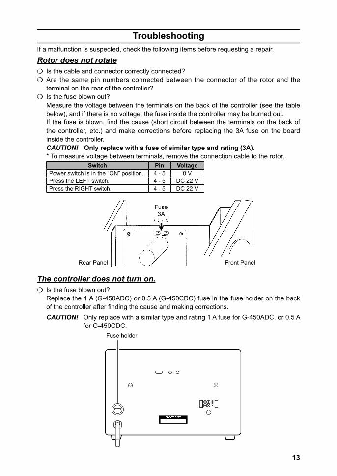
TroubleshootingIf a malfunction is suspected, check the following items before requesting a repair.
Rotor does not rotatem Is the cable and connector correctly connected?m Are the same pin numbers connected between the connector of the rotor and the
terminal on the rear of the controller?m Is the fuse blown out?
Measure the voltage between the terminals on the back of the controller (see the table below), and if there is no voltage, the fuse inside the controller may be burned out.If the fuse is blown, find the cause (short circuit between the terminals on the back of the controller, etc.) and make corrections before replacing the 3A fuse on the board inside the controller.CAUTION! Only replace with a fuse of similar type and rating (3A).* To measure voltage between terminals, remove the connection cable to the rotor.
Switch Pin VoltagePower switch is in the “ON” position. 4 - 5 0 VPress the LEFT switch. 4 - 5 DC 22 VPress the RIGHT switch. 4 - 5 DC 22 V
Fuse3A
Front PanelRear Panel
The controller does not turn on.m Is the fuse blown out?
Replace the 1 A (G-450ADC) or 0.5 A (G-450CDC) fuse in the fuse holder on the back of the controller after finding the cause and making corrections.CAUTION! Only replace with a similar type and rating 1 A fuse for G-450ADC, or 0.5 A
for G-450CDC.Fuse holder
14
YAESU LIMITED WARRANTYLimited Warranty is valid only in the country/region where this product was originally purchased.On-line Warranty Registration:Thank you for buying YAESU products! We are confident your new radio will serve your needs for many years! Please register your product at www.yaesu.com - Owner’s CornerWarranty Terms:Subject to the Limitations of the Warranty and the Warranty Procedures described below, YAESU MUSEN hereby warrants this product to be free of defects in materials and workmanship in normal use during the “Warranty Period.” (the “Limited Warranty”).Limitations of Warranty:A. YAESU MUSEN is not liable for any express warranties except the Limited Warranty
described above.B. The Limited Warranty is extended only to the original end-use purchaser or the person
receiving this product as a gift, and shall not be extended to any other person or transferee.C. Unless a different warranty period is stated with this YAESU product, the Warranty Period
is three years from the date of retail purchase by the original end-use purchaser.D. The Limited Warranty is valid only in the country/region where this product was originally
purchased.E. During the Warranty Period, YAESU MUSEN will, at its sole option, repair or replace
(using new or refurbished replacement parts) any defective parts within a reasonable period of time and free of charge.
F. The Limited Warranty does not cover shipping cost (including transportation and insurance) from you to us, or any import fees, duties or taxes.
G. The Limited Warranty does not cover any impairment caused by tampering, misuse, failure to follow instructions supplied with the product, unauthorized modifications, or damage to this product for any reasons, such as: accident; excess moisture; lightning; power surges; connection to improper voltage supply; damage caused by inadequate packing or shipping procedures; loss of, damage to or corruption of stored data; product modification to enable operation in another country/purpose other than the country/purpose for which it was designed, manufactured, approved and/or authorized; or the repair of products damaged by these modifications.
H. The Limited Warranty applies only to the product as it existed at the time of the original purchase, by the original retail purchaser, and shall not preclude YAESU MUSEN from later making any changes in design, adding to, or otherwise improving subsequent versions of this product, or impose upon YAESU MUSEN any obligation to modify or alter this product to conform to such changes, or improvements.
I. YAESU MUSEN assumes no responsibility for any consequential damages caused by, or arising out of, any such defect in materials or workmanship.
J. TO THE FULLEST EXTENT PERMITTED BY LAW, YAESU MUSEN SHALL NOT BE RESPONSIBLE FOR ANY IMPLIED WARRANTY WITH RESPECT TO THIS PRODUCT.
K. If the original retail purchaser timely complies with the Warranty Procedures described below, and YAESU MUSEN elects to send the purchaser a replacement product rather than repair the “original product”, then the Limited Warranty shall apply to the replacement product only for the remainder of the original product Warranty Period.
L. Warranty statutes vary from state to state, or country to country, so some of the above limitations may not apply to your location.
15
Warranty Procedures:1. To find the Authorized YAESU Service Center in your country/region, visit www.yaesu.
com. Contact the YAESU Service Center for specific return and shipping instructions, or contact an authorized YAESU dealer/distributor from whom the product was originally purchased.
2. Include proof of original purchase from an authorized YAESU dealer/distributor, and ship the product, freight prepaid, to the address provided by the YAESU Service Center in your country/ region.
3. Upon receipt of this product, returned in accordance with the procedures described above, by the YAESU Authorized Service Center, all reasonable efforts will be expended by YAESU MUSEN to cause this product to conform to its original specifications. YAESU MUSEN will return the repaired product (or a replacement product) free of charge to the original purchaser. The decision to repair or replace this product is the sole discretion of YAESU MUSEN.
Other conditions:YAESU MUSEN’S MAXIMUM LIABILITY SHALL NOT EXCEED THE ACTUAL PURCHASE PRICE PAID FOR THE PRODUCT. IN NO EVENT SHALL YAESU MUSEN BE LIABLE FOR LOSS OF, DAMAGE TO OR CORRUPTION OF STORED DATA, OR FOR SPECIAL, INCIDENTAL, CONSEQUENTIAL, OR INDIRECT DAMAGES, HOW EVER CAUSED; INCLUDING WITHOUT LIMITATION TO THE REPLACEMENT OF EQUIPMENT AND PROPERTY, AND ANY COSTS OF RECOVERING, PROGRAMMING OR REPRODUCING ANY PROGRAM OR DATA STORED IN OR USED WITH THE YAESU PRODUCT.Some Countries in Europe and some States of the USA do not allow the exclusion or limitation of incidental or consequential damages, or a limitation on how long an implied warranty lasts, so the above limitation or exclusions may not apply. This warranty provides specific rights, there may be other rights available which may vary between countries in Europe or from state to state within the USA.This Limited Warranty is void if the label bearing the serial number has been removed or defaced.
16
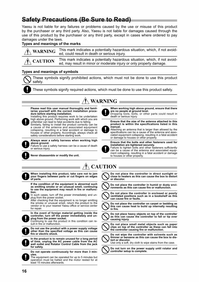
Safety Precautions (Be Sure to Read)Yaesu is not liable for any failures or problems caused by the use or misuse of this product by the purchaser or any third party. Also, Yaesu is not liable for damages caused through the use of this product by the purchaser or any third party, except in cases where ordered to pay damages under the laws.Types and meanings of the marks
WARNING This mark indicates a potentially hazardous situation, which, if not avoid-ed, could result in death or serious injury.
CAUTION This mark indicates a potentially hazardous situation, which, if not avoid-ed, may result in minor or moderate injury or only property damage.
Types and meanings of symbolsThese symbols signify prohibited actions, which must not be done to use this product safely.
These symbols signify required actions, which must be done to use this product safely.
WARNINGPlease read this user manual thoroughly and famil-iarize yourself with the correct installation proce-dure before starting installation.Installing this product requires work to be undertaken high above ground. Performing work with which you are unfamiliar can lead to fatal accidents due to falling.Similarly, failing to install the product correctly can be a cause of the antenna and associated equipment collapsing, resulting in a fatal accident or damage to houses or other property. Accordingly, always check all safety considerations before starting work.
Always wear a safety harness when working high above ground.Failure to use a safety harness can be a cause of death or serious injury.
Never disassemble or modify the unit.
When working high above ground, ensure that there are no people at ground level.Dropping tools, bolts, or other parts could result in death or serious injury.
Ensure that the size of the antenna attached to this product is within the specifications listed in this manual.Attaching an antenna that is larger than allowed by the specifications can be a cause of the antenna and asso-ciated equipment collapsing, resulting in a fatal accident or damage to houses or other property.
Ensure that the bolts and other fasteners used for installation are tightened securely.Failure to tighten bolts and other fasteners sufficiently can be a cause of the antenna and associated equip-ment collapsing, resulting in a fatal accident or damage to houses or other property.
CAUTIONWhen installing this product, take care not to jam your fingers between parts or cut fingers on edges of parts.
If the condition of the equipment is abnormal such as emitting smoke or an unusual smell, continuing to use the equipment may result in fire or malfunc-tion.In such cases, turn off the power immediately and un-plug from the power socket.After checking that the equipment is no longer emitting the smoke or unusual smell, return the product to the vendor or to your nearest Yaesu office or service center for repair.
In the event of foreign material getting inside the controller, turn off the power immediately and un-plug from the power socket.Continuing to use the product in this condition can re-sult in fire or malfunction.
Do not use the product with a power supply voltage other than the specified voltage as this can cause fire or electric shock.
In the product is to remain unused for a long period of time, unplug the AC power cable from the AC wall outlet and Rotator Control Cable from the jack for safety.
Do not operate continuously for more than 3 min-utes.The equipment can be operated for up to 5 minutes but operation must be halted and the motor rested for at least 15 minutes afterwards.
Do not place the controller in direct sunlight or close to heaters as this can cause the box to distort or discolor.
Do not place the controller in humid or dusty envi-ronments as this can cause fire or malfunction.
Do not place the controller in enclosed or poorly ventilated positions such as in a bookshelf as this can cause fire or faults.
Do not place the controller on carpet or bedding as this can cause heat to build up internally resulting in fire.
Do not place heavy objects on top of the controller as this can cause the controller to fall or tip over causing injury.
Do not place small metal objects such as paper clips on top of the controller as these can fall into the controller causing fire or malfunction.
Do not wipe the controller with solvents such as thinner or benzene as this can cause the box to dis-tort or discolor.Use only a soft, dry cloth to wipe stains from the case.
Do not turn on the power supply until rotator and controller setup is complete.
Disposal of Electronic and Electrical EquipmentProducts with the symbol (crossed-out wheeled bin) cannot be disposed as household waste.Electronic and Electrical Equipment should be recycled at a facility ca-pable of handling these items and their waste by-products.Please contact a local equipment supplier representative or service cen-ter for information about the waste collection system in your country.
Printed in Japan
Copyright 2019YAESU MUSEN CO., LTD.All rights reserved.No portion of this manual may bereproduced without the permission ofYAESU MUSEN CO., LTD.
YAESU MUSEN CO., LTD.Tennozu Parkside Building2-5-8 Higashi-Shinagawa, Shinagawa-ku, Tokyo 140-0002 JapanYAESU USA6125 Phyllis Drive, Cypress, CA 90630, U.S.A.YAESU UKUnit 12, Sun Valley Business Park, Winnall CloseWinchester, Hampshire, SO23 0LB, U.K.
1907V-AS


![Yaesu Vx 8r User Manual[1]](https://img.pdfslide.us/doc/110x75/577ccfb21a28ab9e789054fc/yaesu-vx-8r-user-manual1.jpg)