Embed Size (px)
Citation preview
DIC183
36P-28199-10
FZ6RY(C)
OWNER’S MANUAL
Read this manual carefully before operating this vehicle.
LIT-11626-22-77
EAU10042
Read this manual carefully before operating this vehicle. This manual should stay with this vehicle if it is sold.
U36P10E0.book Page 1 Thursday, November 13, 2008 4:45 PM

INTRODUCTIONEAU10083
Congratulations on your purchase of the Yamaha FZ6RY(C). This model is the result of Yamaha’s vast experience in theproduction of fine sporting, touring, and pacesetting racing machines. It represents the high degree of craftsmanship andreliability that have made Yamaha a leader in these fields.This manual will give you an understanding of the operation, inspection, and basic maintenance of this motorcycle. If youhave any questions concerning the operation or maintenance of your motorcycle, please consult a Yamaha dealer.The design and manufacture of this Yamaha motorcycle fully comply with the emissions standards for clean air applicable atthe date of manufacture. Yamaha has met these standards without reducing the performance or economy of operation of themotorcycle. To maintain these high standards, it is important that you and your Yamaha dealer pay close attention to therecommended maintenance schedules and operating instructions contained within this manual.Yamaha continually seeks advancements in product design and quality. Therefore, while this manual contains the most cur-rent product information available at the time of printing, there may be minor discrepancies between your motorcycle and thismanual. If there is any question concerning this manual, please consult a Yamaha dealer.
WARNINGEWA10011
Please read this manual and the “YOU AND YOUR MOTORCYCLE: RIDING TIPS” booklet carefully before operatingthis motorcycle. Do not attempt to operate this motorcycle until you have attained adequate knowledge of its con-trols and operating features. Regular inspections and careful maintenance, along with good operating techniques,will help ensure that you safely enjoy the capabilities and reliability of this motorcycle.
U36P10E0.book Page 1 Thursday, November 13, 2008 4:45 PM
IMPORTANT MANUAL INFORMATIONEAU10132
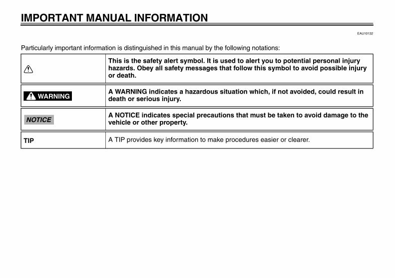
Particularly important information is distinguished in this manual by the following notations:
This is the safety alert symbol. It is used to alert you to potential personal injury hazards. Obey all safety messages that follow this symbol to avoid possible injury or death.
A WARNING indicates a hazardous situation which, if not avoided, could result in death or serious injury.
A NOTICE indicates special precautions that must be taken to avoid damage to the vehicle or other property.
A TIP provides key information to make procedures easier or clearer.
WARNING
NOTICE
TIP
U36P10E0.book Page 1 Thursday, November 13, 2008 4:45 PM
IMPORTANT MANUAL INFORMATION
EAU10193
FZ6RY(C)OWNER’S MANUAL
©2008 by Yamaha Motor Corporation, U.S.A.1st edition, October 2008
All rights reserved.Any reprinting or unauthorized use without the written permission of Yamaha Motor Corporation, U.S.A.
is expressly prohibited.Printed in Japan.
P/N LIT-11626-22-77
U36P10E0.book Page 2 Thursday, November 13, 2008 4:45 PM
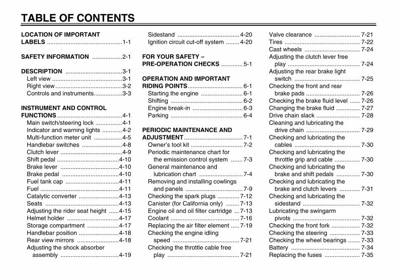
TABLE OF CONTENTSLOCATION OF IMPORTANT LABELS .............................................1-1
SAFETY INFORMATION ..................2-1
DESCRIPTION ..................................3-1Left view ..........................................3-1Right view ........................................3-2Controls and instruments.................3-3
INSTRUMENT AND CONTROL FUNCTIONS .......................................4-1
Main switch/steering lock ................4-1Indicator and warning lights ............4-2Multi-function meter unit .................4-5Handlebar switches ........................4-8Clutch lever .....................................4-9Shift pedal .....................................4-10Brake lever ...................................4-10Brake pedal ..................................4-10Fuel tank cap ................................4-11Fuel ...............................................4-11Catalytic converter ........................4-13Seats ............................................4-13Adjusting the rider seat height ......4-15Helmet holder ...............................4-17Storage compartment ...................4-17Handlebar position ........................4-18Rear view mirrors .........................4-18Adjusting the shock absorber
assembly ...................................4-19
Sidestand ..................................... 4-20Ignition circuit cut-off system ........ 4-20
FOR YOUR SAFETY – PRE-OPERATION CHECKS ............. 5-1
OPERATION AND IMPORTANT RIDING POINTS................................. 6-1
Starting the engine ......................... 6-1Shifting ........................................... 6-2Engine break-in .............................. 6-3Parking ........................................... 6-4
PERIODIC MAINTENANCE AND ADJUSTMENT ................................... 7-1
Owner’s tool kit ............................... 7-2Periodic maintenance chart for
the emission control system ....... 7-3General maintenance and
lubrication chart .......................... 7-4Removing and installing cowlings
and panels .................................. 7-9Checking the spark plugs ............. 7-12Canister (for California only) ........ 7-13Engine oil and oil filter cartridge ... 7-13Coolant ......................................... 7-16Replacing the air filter element ..... 7-19Checking the engine idling
speed ........................................ 7-21Checking the throttle cable free
play ........................................... 7-21
Valve clearance ........................... 7-21Tires ............................................. 7-22Cast wheels ................................. 7-24Adjusting the clutch lever free
play ........................................... 7-24Adjusting the rear brake light
switch ....................................... 7-25Checking the front and rear
brake pads ................................ 7-26Checking the brake fluid level ...... 7-26Changing the brake fluid .............. 7-27Drive chain slack .......................... 7-28Cleaning and lubricating the
drive chain ................................ 7-29Checking and lubricating the
cables ....................................... 7-30Checking and lubricating the
throttle grip and cable ............... 7-30Checking and lubricating the
brake and shift pedals .............. 7-30Checking and lubricating the
brake and clutch levers ............ 7-31Checking and lubricating the
sidestand .................................. 7-32Lubricating the swingarm
pivots ........................................ 7-32Checking the front fork ................. 7-32Checking the steering .................. 7-33Checking the wheel bearings ....... 7-33Battery ......................................... 7-34Replacing the fuses ..................... 7-35
U36P10E0.book Page 1 Thursday, November 13, 2008 4:45 PM

TABLE OF CONTENTSReplacing the headlight bulb ........7-36Replacing the tail/brake light
bulb ...........................................7-37Replacing a turn signal light
bulb ...........................................7-38Replacing the license plate light
bulb ...........................................7-38Supporting the motorcycle ............7-39Front wheel ...................................7-39Rear wheel ...................................7-40Troubleshooting ............................7-42Troubleshooting charts .................7-43
MOTORCYCLE CARE AND STORAGE ..........................................8-1
Matte color caution .........................8-1Care ................................................8-1Storage ...........................................8-3
SPECIFICATIONS .............................9-1
CONSUMER INFORMATION...........10-1Identification numbers ..................10-1Reporting safety defects ...............10-3Motorcycle noise regulation ..........10-4Maintenance record ......................10-5YAMAHA MOTOR
CORPORATION, U.S.A. STREET AND ENDURO MOTORCYCLE LIMITED WARRANTY .............................10-7
YAMAHA EXTENDED SERVICE (Y.E.S.) ..................................... 10-9
U36P10E0.book Page 2 Thursday, November 13, 2008 4:45 PM

LOCATION OF IMPORTANT LABELS
1-1
1
EAU10383
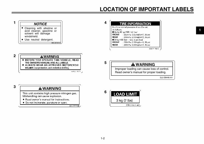
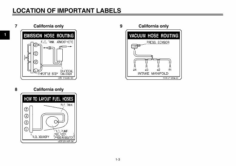
Read and understand all of the labels on your vehicle. They contain important information for safe and proper operation ofyour vehicle. Never remove any labels from your vehicle. If a label becomes difficult to read or comes off, a replacement labelis available from your Yamaha dealer.
1 2 3 4 5,6,7,8,9
U36P10E0.book Page 1 Thursday, November 13, 2008 4:45 PM
LOCATION OF IMPORTANT LABELS
1-2
1
4
5
6
1
2
3
Cleaning with alkaline oracid cleaner, gasoline orsolvent will damagewindshield.Use neutral detergent.
WARNINGImproper loading can cause loss of control.Read owner’s manual for proper loading.
3JJ-28446-A1
NOTICE
4B5-2815K-00
U36P10E0.book Page 2 Thursday, November 13, 2008 4:45 PM
LOCATION OF IMPORTANT LABELS
1-3
1
California only8
California only 9 California only7
U36P10E0.book Page 3 Thursday, November 13, 2008 4:45 PM
2-1
2
SAFETY INFORMATIONEAU10283
Be a Responsible OwnerAs the vehicle’s owner, you are respon-sible for the safe and proper operationof your motorcycle.Motorcycles are single-track vehicles.Their safe use and operation are de-pendent upon the use of proper ridingtechniques as well as the expertise ofthe operator. Every operator shouldknow the following requirements beforeriding this motorcycle.He or she should:
� Obtain thorough instructions froma competent source on all aspectsof motorcycle operation.
� Observe the warnings and mainte-nance requirements in this Own-er’s Manual.
� Obtain qualified training in safeand proper riding techniques.
� Obtain professional technical ser-vice as indicated in this Owner’sManual and/or when made neces-sary by mechanical conditions.
Safe RidingPerform the pre-operation checks eachtime you use the vehicle to make sure itis in safe operating condition. Failure toinspect or maintain the vehicle properlyincreases the possibility of an accidentor equipment damage. See page 5-1for a list of pre-operation checks.
� This motorcycle is designed to car-ry the operator and a passenger.
� The failure of motorists to detectand recognize motorcycles in traf-fic is the predominating cause ofautomobile/motorcycle accidents.Many accidents have been causedby an automobile driver who didnot see the motorcycle. Makingyourself conspicuous appears tobe very effective in reducing thechance of this type of accident.Therefore:• Wear a brightly colored jacket.• Use extra caution when you are
approaching and passingthrough intersections, since in-tersections are the most likelyplaces for motorcycle accidentsto occur.
• Ride where other motorists cansee you. Avoid riding in anothermotorist’s blind spot.
� Many accidents involve inexperi-enced operators. In fact, many op-erators who have been involved inaccidents do not even have a cur-rent motorcycle license.• Make sure that you are qualified
and that you only lend yourmotorcycle to other qualified op-erators.
• Know your skills and limits.Staying within your limits mayhelp you to avoid an accident.
• We recommend that you prac-tice riding your motorcyclewhere there is no traffic until youhave become thoroughly famil-iar with the motorcycle and all ofits controls.
� Many accidents have been causedby error of the motorcycle opera-tor. A typical error made by the op-erator is veering wide on a turn
U36P10E0.book Page 1 Thursday, November 13, 2008 4:45 PM
SAFETY INFORMATION
2-2
2
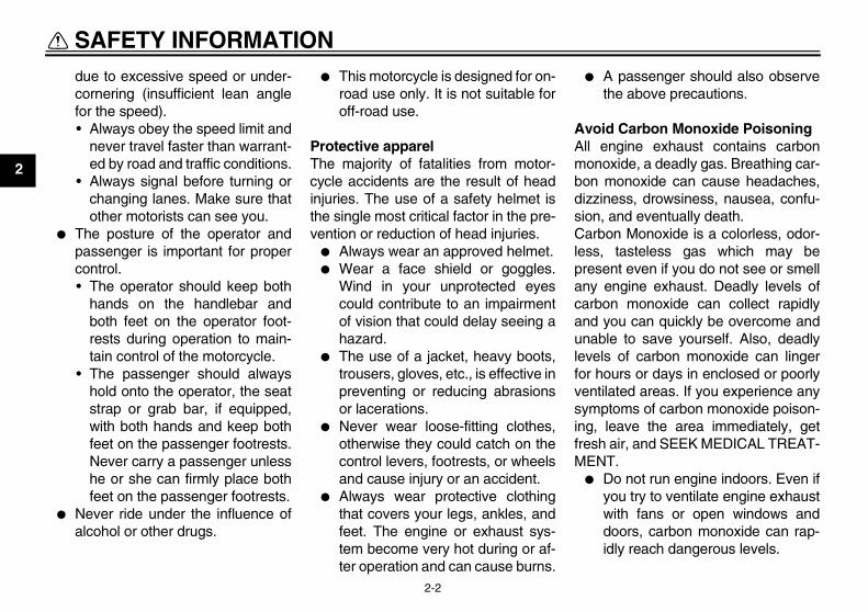
due to excessive speed or under-cornering (insufficient lean anglefor the speed).• Always obey the speed limit and
never travel faster than warrant-ed by road and traffic conditions.
• Always signal before turning orchanging lanes. Make sure thatother motorists can see you.
� The posture of the operator andpassenger is important for propercontrol.• The operator should keep both
hands on the handlebar andboth feet on the operator foot-rests during operation to main-tain control of the motorcycle.
• The passenger should alwayshold onto the operator, the seatstrap or grab bar, if equipped,with both hands and keep bothfeet on the passenger footrests.Never carry a passenger unlesshe or she can firmly place bothfeet on the passenger footrests.
� Never ride under the influence ofalcohol or other drugs.
� This motorcycle is designed for on-road use only. It is not suitable foroff-road use.
Protective apparelThe majority of fatalities from motor-cycle accidents are the result of headinjuries. The use of a safety helmet isthe single most critical factor in the pre-vention or reduction of head injuries.
� Always wear an approved helmet.� Wear a face shield or goggles.
Wind in your unprotected eyescould contribute to an impairmentof vision that could delay seeing ahazard.
� The use of a jacket, heavy boots,trousers, gloves, etc., is effective inpreventing or reducing abrasionsor lacerations.
� Never wear loose-fitting clothes,otherwise they could catch on thecontrol levers, footrests, or wheelsand cause injury or an accident.
� Always wear protective clothingthat covers your legs, ankles, andfeet. The engine or exhaust sys-tem become very hot during or af-ter operation and can cause burns.
� A passenger should also observethe above precautions.
Avoid Carbon Monoxide PoisoningAll engine exhaust contains carbonmonoxide, a deadly gas. Breathing car-bon monoxide can cause headaches,dizziness, drowsiness, nausea, confu-sion, and eventually death.Carbon Monoxide is a colorless, odor-less, tasteless gas which may bepresent even if you do not see or smellany engine exhaust. Deadly levels ofcarbon monoxide can collect rapidlyand you can quickly be overcome andunable to save yourself. Also, deadlylevels of carbon monoxide can lingerfor hours or days in enclosed or poorlyventilated areas. If you experience anysymptoms of carbon monoxide poison-ing, leave the area immediately, getfresh air, and SEEK MEDICAL TREAT-MENT.
� Do not run engine indoors. Even ifyou try to ventilate engine exhaustwith fans or open windows anddoors, carbon monoxide can rap-idly reach dangerous levels.
U36P10E0.book Page 2 Thursday, November 13, 2008 4:45 PM
SAFETY INFORMATION
2-3
2
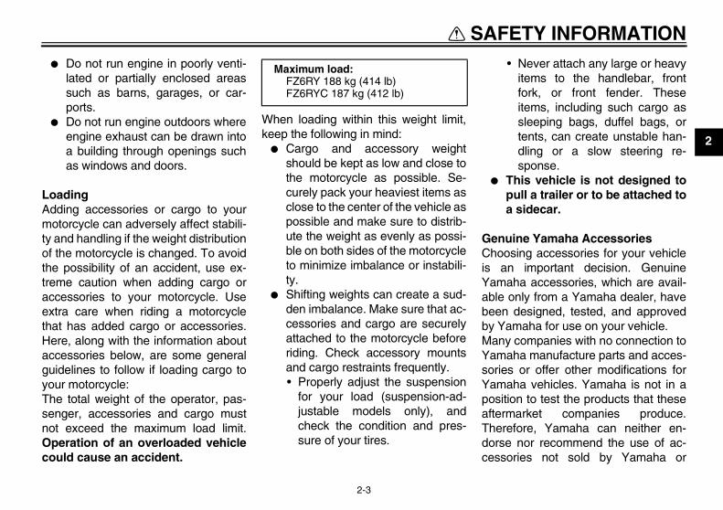
� Do not run engine in poorly venti-lated or partially enclosed areassuch as barns, garages, or car-ports.
� Do not run engine outdoors whereengine exhaust can be drawn intoa building through openings suchas windows and doors.
LoadingAdding accessories or cargo to yourmotorcycle can adversely affect stabili-ty and handling if the weight distributionof the motorcycle is changed. To avoidthe possibility of an accident, use ex-treme caution when adding cargo oraccessories to your motorcycle. Useextra care when riding a motorcyclethat has added cargo or accessories.Here, along with the information aboutaccessories below, are some generalguidelines to follow if loading cargo toyour motorcycle:The total weight of the operator, pas-senger, accessories and cargo mustnot exceed the maximum load limit.Operation of an overloaded vehiclecould cause an accident.
When loading within this weight limit,keep the following in mind:
� Cargo and accessory weightshould be kept as low and close tothe motorcycle as possible. Se-curely pack your heaviest items asclose to the center of the vehicle aspossible and make sure to distrib-ute the weight as evenly as possi-ble on both sides of the motorcycleto minimize imbalance or instabili-ty.
� Shifting weights can create a sud-den imbalance. Make sure that ac-cessories and cargo are securelyattached to the motorcycle beforeriding. Check accessory mountsand cargo restraints frequently.• Properly adjust the suspension
for your load (suspension-ad-justable models only), andcheck the condition and pres-sure of your tires.
• Never attach any large or heavyitems to the handlebar, frontfork, or front fender. Theseitems, including such cargo assleeping bags, duffel bags, ortents, can create unstable han-dling or a slow steering re-sponse.
� This vehicle is not designed topull a trailer or to be attached toa sidecar.
Genuine Yamaha AccessoriesChoosing accessories for your vehicleis an important decision. GenuineYamaha accessories, which are avail-able only from a Yamaha dealer, havebeen designed, tested, and approvedby Yamaha for use on your vehicle.Many companies with no connection toYamaha manufacture parts and acces-sories or offer other modifications forYamaha vehicles. Yamaha is not in aposition to test the products that theseaftermarket companies produce.Therefore, Yamaha can neither en-dorse nor recommend the use of ac-cessories not sold by Yamaha or
Maximum load:FZ6RY 188 kg (414 lb)FZ6RYC 187 kg (412 lb)
U36P10E0.book Page 3 Thursday, November 13, 2008 4:45 PM
SAFETY INFORMATION
2-4
2
modifications not specifically recom-mended by Yamaha, even if sold andinstalled by a Yamaha dealer.
Aftermarket Parts, Accessories, andModificationsWhile you may find aftermarket prod-ucts similar in design and quality togenuine Yamaha accessories, recog-nize that some aftermarket accessoriesor modifications are not suitable be-cause of potential safety hazards to youor others. Installing aftermarket prod-ucts or having other modifications per-formed to your vehicle that change anyof the vehicle’s design or operationcharacteristics can put you and othersat greater risk of serious injury or death.You are responsible for injuries relatedto changes in the vehicle.Keep the following guidelines in mind,as well as those provided under “Load-ing” when mounting accessories.
� Never install accessories or carrycargo that would impair the perfor-mance of your motorcycle. Care-fully inspect the accessory beforeusing it to make sure that it doesnot in any way reduce ground
clearance or cornering clearance,limit suspension travel, steeringtravel or control operation, or ob-scure lights or reflectors.• Accessories fitted to the handle-
bar or the front fork area cancreate instability due to improperweight distribution or aerody-namic changes. If accessoriesare added to the handlebar orfront fork area, they must be aslightweight as possible andshould be kept to a minimum.
• Bulky or large accessories mayseriously affect the stability ofthe motorcycle due to aerody-namic effects. Wind may at-tempt to lift the motorcycle, orthe motorcycle may become un-stable in cross winds. These ac-cessories may also causeinstability when passing or beingpassed by large vehicles.
• Certain accessories can dis-place the operator from his orher normal riding position. Thisimproper position limits the free-dom of movement of the opera-
tor and may limit control ability,therefore, such accessories arenot recommended.
� Use caution when adding electri-cal accessories. If electrical acces-sories exceed the capacity of themotorcycle’s electrical system, anelectric failure could result, whichcould cause a dangerous loss oflights or engine power.
Aftermarket Tires and RimsThe tires and rims that came with yourmotorcycle were designed to match theperformance capabilities and to providethe best combination of handling, brak-ing, and comfort. Other tires, rims, siz-es, and combinations may not beappropriate. Refer to page 7-22 for tirespecifications and more information onreplacing your tires.
U36P10E0.book Page 4 Thursday, November 13, 2008 4:45 PM
DESCRIPTION
3-1
3
EAU10410
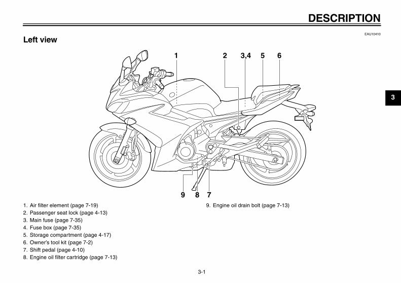
Left view
1 2 3,4 5 6
7891. Air filter element (page 7-19)2. Passenger seat lock (page 4-13)3. Main fuse (page 7-35)4. Fuse box (page 7-35)5. Storage compartment (page 4-17)6. Owner’s tool kit (page 7-2)7. Shift pedal (page 4-10)8. Engine oil filter cartridge (page 7-13)
9. Engine oil drain bolt (page 7-13)
U36P10E0.book Page 1 Thursday, November 13, 2008 4:45 PM
DESCRIPTION
3-2
3
EAU10420
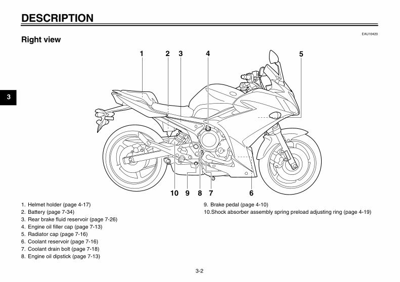
Right view
678910
51 2 3 4
1. Helmet holder (page 4-17)2. Battery (page 7-34)3. Rear brake fluid reservoir (page 7-26)4. Engine oil filler cap (page 7-13)5. Radiator cap (page 7-16)6. Coolant reservoir (page 7-16)7. Coolant drain bolt (page 7-18)8. Engine oil dipstick (page 7-13)
9. Brake pedal (page 4-10)10.Shock absorber assembly spring preload adjusting ring (page 4-19)
U36P10E0.book Page 2 Thursday, November 13, 2008 4:45 PM
DESCRIPTION
3-3
3
EAU10430
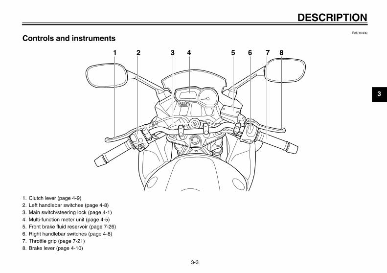
Controls and instruments
1 2 3 5 6 7 84
1. Clutch lever (page 4-9)2. Left handlebar switches (page 4-8)3. Main switch/steering lock (page 4-1)4. Multi-function meter unit (page 4-5)5. Front brake fluid reservoir (page 7-26)6. Right handlebar switches (page 4-8)7. Throttle grip (page 7-21)8. Brake lever (page 4-10)
U36P10E0.book Page 3 Thursday, November 13, 2008 4:45 PM
INSTRUMENT AND CONTROL FUNCTIONS
4-1
4
EAU10460
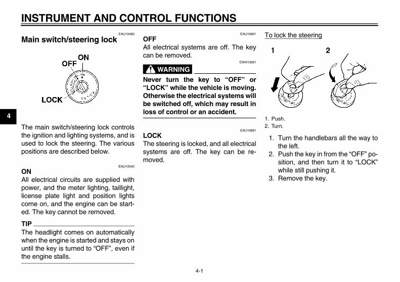
Main switch/steering lock
The main switch/steering lock controlsthe ignition and lighting systems, and isused to lock the steering. The variouspositions are described below.
EAU10540
ONAll electrical circuits are supplied withpower, and the meter lighting, taillight,license plate light and position lightscome on, and the engine can be start-ed. The key cannot be removed.
TIPThe headlight comes on automaticallywhen the engine is started and stays onuntil the key is turned to “OFF”, even ifthe engine stalls.
EAU10661
OFFAll electrical systems are off. The keycan be removed.
WARNINGEWA10061
Never turn the key to “OFF” or“LOCK” while the vehicle is moving.Otherwise the electrical systems willbe switched off, which may result inloss of control or an accident.
EAU10681
LOCKThe steering is locked, and all electricalsystems are off. The key can be re-moved.
To lock the steering
1. Turn the handlebars all the way tothe left.
2. Push the key in from the “OFF” po-sition, and then turn it to “LOCK”while still pushing it.
3. Remove the key.
1. Push.2. Turn.
U36P10E0.book Page 1 Thursday, November 13, 2008 4:45 PM
INSTRUMENT AND CONTROL FUNCTIONS
4-2
4
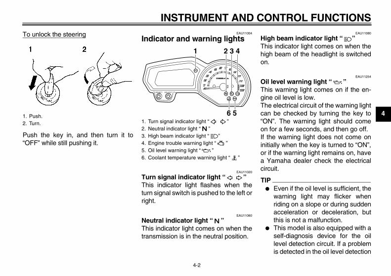
To unlock the steering
Push the key in, and then turn it to“OFF” while still pushing it.
EAU11004
Indicator and warning lights
EAU11020
Turn signal indicator light “ ” This indicator light flashes when theturn signal switch is pushed to the left orright.
EAU11060
Neutral indicator light “ ” This indicator light comes on when thetransmission is in the neutral position.
EAU11080
High beam indicator light “ ” This indicator light comes on when thehigh beam of the headlight is switchedon.
EAU11254
Oil level warning light “ ” This warning light comes on if the en-gine oil level is low.The electrical circuit of the warning lightcan be checked by turning the key to“ON”. The warning light should comeon for a few seconds, and then go off.If the warning light does not come oninitially when the key is turned to “ON”,or if the warning light remains on, havea Yamaha dealer check the electricalcircuit.
TIP� Even if the oil level is sufficient, the
warning light may flicker whenriding on a slope or during suddenacceleration or deceleration, butthis is not a malfunction.
� This model is also equipped with aself-diagnosis device for the oillevel detection circuit. If a problemis detected in the oil level detection
1. Push.2. Turn. 1. Turn signal indicator light “ ”
2. Neutral indicator light “ ”3. High beam indicator light “ ”4. Engine trouble warning light “ ”5. Oil level warning light “ ”6. Coolant temperature warning light “ ”
1 2 3 4
6 5
U36P10E0.book Page 2 Thursday, November 13, 2008 4:45 PM
INSTRUMENT AND CONTROL FUNCTIONS
4-3
4
circuit, the following cycle will berepeated until the malfunction iscorrected: The oil level warninglight will flash ten times, then go offfor 2.5 seconds. If this occurs,have a Yamaha dealer check thevehicle.
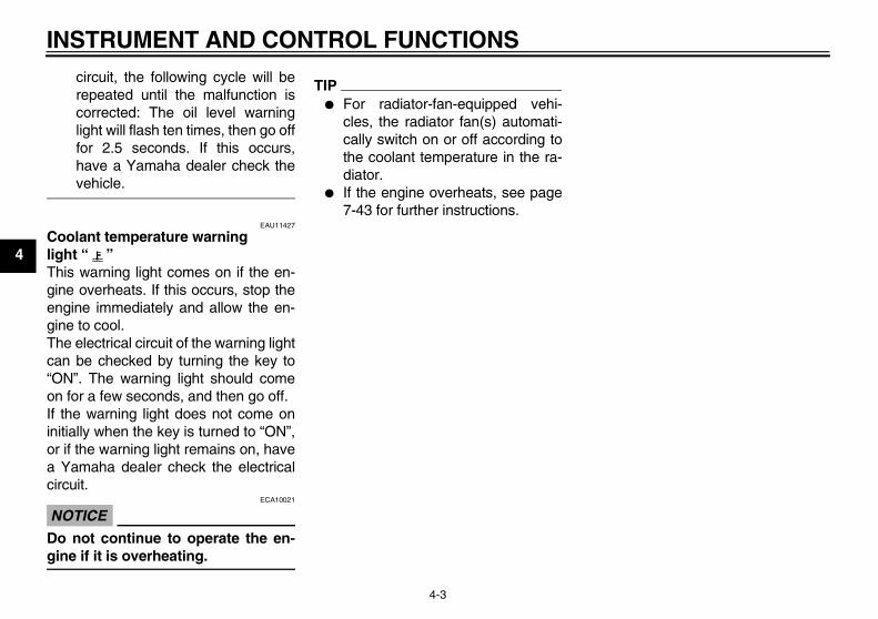
EAU11427
Coolant temperature warning light “ ” This warning light comes on if the en-gine overheats. If this occurs, stop theengine immediately and allow the en-gine to cool.The electrical circuit of the warning lightcan be checked by turning the key to“ON”. The warning light should comeon for a few seconds, and then go off.If the warning light does not come oninitially when the key is turned to “ON”,or if the warning light remains on, havea Yamaha dealer check the electricalcircuit.
NOTICEECA10021
Do not continue to operate the en-gine if it is overheating.
TIP� For radiator-fan-equipped vehi-
cles, the radiator fan(s) automati-cally switch on or off according tothe coolant temperature in the ra-diator.
� If the engine overheats, see page7-43 for further instructions.
U36P10E0.book Page 3 Thursday, November 13, 2008 4:45 PM
INSTRUMENT AND CONTROL FUNCTIONS
4-4
4
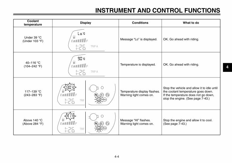
Coolant temperature Display Conditions What to do
Under 39 °C (Under 103 °F) Message “Lo” is displayed. OK. Go ahead with riding.
40–116 °C (104–242 °F) Temperature is displayed. OK. Go ahead with riding.
117–139 °C (243–283 °F)
Temperature display flashes.Warning light comes on.
Stop the vehicle and allow it to idle until the coolant temperature goes down.If the temperature does not go down, stop the engine. (See page 7-43.)
Above 140 °C (Above 284 °F)
Message “HI” flashes.Warning light comes on.
Stop the engine and allow it to cool. (See page 7-43.)
U36P10E0.book Page 4 Thursday, November 13, 2008 4:45 PM
INSTRUMENT AND CONTROL FUNCTIONS
4-5
4
EAU11534
Engine trouble warning light “ ” This warning light comes on or flashesif a problem is detected in the electricalcircuit monitoring the engine. If this oc-curs, have a Yamaha dealer check theself-diagnosis system. (See page 4-8for an explanation of the self-diagnosisdevice.)The electrical circuit of the warning lightcan be checked by turning the key to“ON”. The warning light should comeon for a few seconds, and then go off.If the warning light does not come oninitially when the key is turned to “ON”,or if the warning light remains on, havea Yamaha dealer check the electricalcircuit.
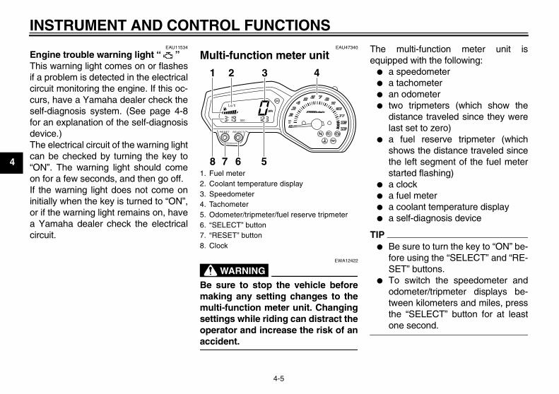
EAU47340
Multi-function meter unit
WARNINGEWA12422
Be sure to stop the vehicle beforemaking any setting changes to themulti-function meter unit. Changingsettings while riding can distract theoperator and increase the risk of anaccident.
The multi-function meter unit isequipped with the following:
� a speedometer� a tachometer� an odometer� two tripmeters (which show the
distance traveled since they werelast set to zero)
� a fuel reserve tripmeter (whichshows the distance traveled sincethe left segment of the fuel meterstarted flashing)
� a clock� a fuel meter� a coolant temperature display� a self-diagnosis device
TIP� Be sure to turn the key to “ON” be-
fore using the “SELECT” and “RE-SET” buttons.
� To switch the speedometer andodometer/tripmeter displays be-tween kilometers and miles, pressthe “SELECT” button for at leastone second.
1. Fuel meter2. Coolant temperature display3. Speedometer4. Tachometer5. Odometer/tripmeter/fuel reserve tripmeter6. “SELECT” button7. “RESET” button8. Clock
1
8
2 3 4
7 6 5
U36P10E0.book Page 5 Thursday, November 13, 2008 4:45 PM
INSTRUMENT AND CONTROL FUNCTIONS
4-6
4
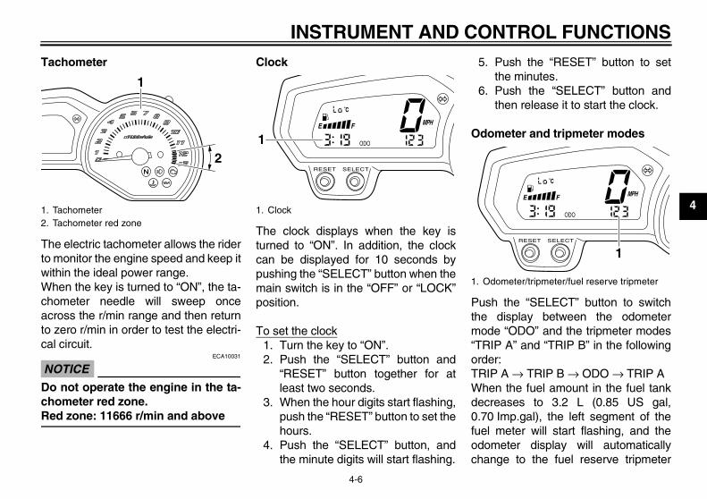
Tachometer
The electric tachometer allows the riderto monitor the engine speed and keep itwithin the ideal power range.When the key is turned to “ON”, the ta-chometer needle will sweep onceacross the r/min range and then returnto zero r/min in order to test the electri-cal circuit.
NOTICEECA10031
Do not operate the engine in the ta-chometer red zone.Red zone: 11666 r/min and above
Clock
The clock displays when the key isturned to “ON”. In addition, the clockcan be displayed for 10 seconds bypushing the “SELECT” button when themain switch is in the “OFF” or “LOCK”position.
To set the clock1. Turn the key to “ON”.2. Push the “SELECT” button and
“RESET” button together for atleast two seconds.
3. When the hour digits start flashing,push the “RESET” button to set thehours.
4. Push the “SELECT” button, andthe minute digits will start flashing.
5. Push the “RESET” button to setthe minutes.
6. Push the “SELECT” button andthen release it to start the clock.
Odometer and tripmeter modes
Push the “SELECT” button to switchthe display between the odometermode “ODO” and the tripmeter modes“TRIP A” and “TRIP B” in the followingorder:TRIP A → TRIP B → ODO → TRIP AWhen the fuel amount in the fuel tankdecreases to 3.2 L (0.85 US gal,0.70 Imp.gal), the left segment of thefuel meter will start flashing, and theodometer display will automaticallychange to the fuel reserve tripmeter
1. Tachometer2. Tachometer red zone
1
2
1. Clock
1
1. Odometer/tripmeter/fuel reserve tripmeter
1
U36P10E0.book Page 6 Thursday, November 13, 2008 4:45 PM
INSTRUMENT AND CONTROL FUNCTIONS
4-7
4
mode “F-TRIP” and start counting thedistance traveled from that point. In thatcase, push the “SELECT” button toswitch the display between the varioustripmeter and odometer modes in thefollowing order:F-TRIP → TRIP A → TRIP B → ODO→ F-TRIPTo reset a tripmeter, select it by push-ing the “SELECT” button, and thenpush the “RESET” button for at leastone second. If you do not reset the fuelreserve tripmeter manually, it will resetitself automatically and the display willreturn to the prior mode after refuelingand traveling 5 km (3 mi).
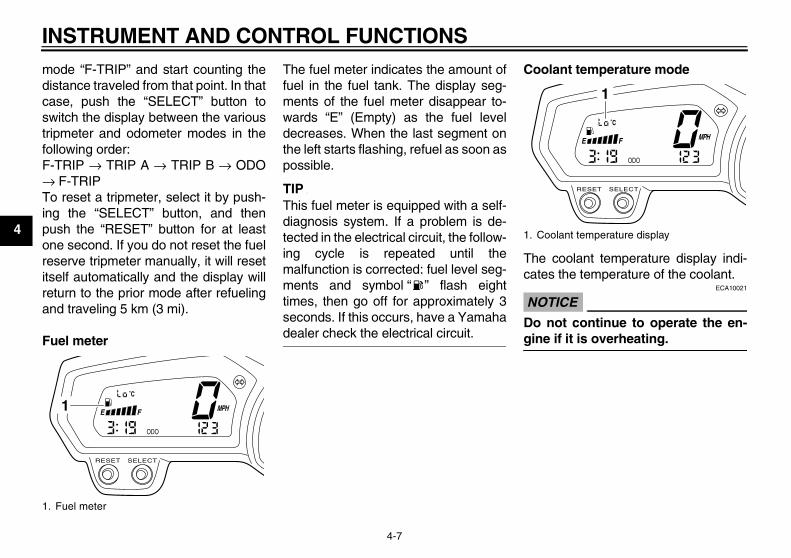
Fuel meter
The fuel meter indicates the amount offuel in the fuel tank. The display seg-ments of the fuel meter disappear to-wards “E” (Empty) as the fuel leveldecreases. When the last segment onthe left starts flashing, refuel as soon aspossible.
TIPThis fuel meter is equipped with a self-diagnosis system. If a problem is de-tected in the electrical circuit, the follow-ing cycle is repeated until themalfunction is corrected: fuel level seg-ments and symbol “ ” flash eighttimes, then go off for approximately 3seconds. If this occurs, have a Yamahadealer check the electrical circuit.
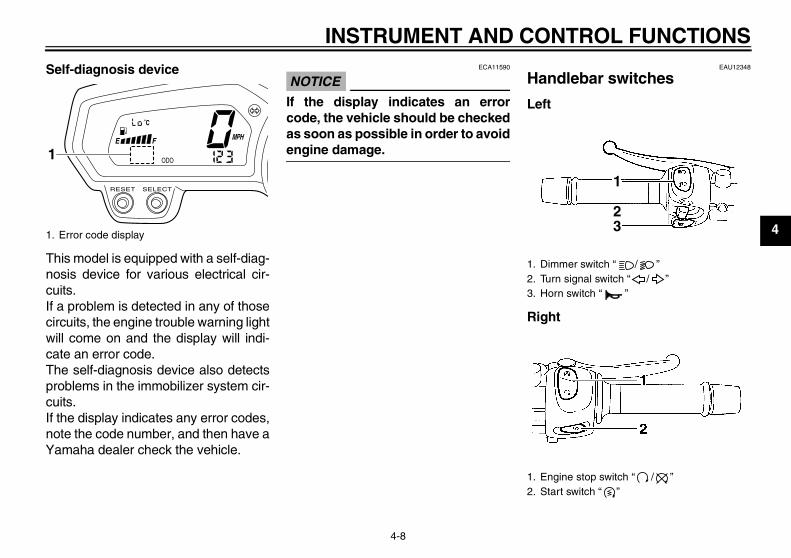
Coolant temperature mode
The coolant temperature display indi-cates the temperature of the coolant.
NOTICEECA10021
Do not continue to operate the en-gine if it is overheating.
1. Fuel meter
1
1. Coolant temperature display
1
U36P10E0.book Page 7 Thursday, November 13, 2008 4:45 PM
INSTRUMENT AND CONTROL FUNCTIONS
4-8
4
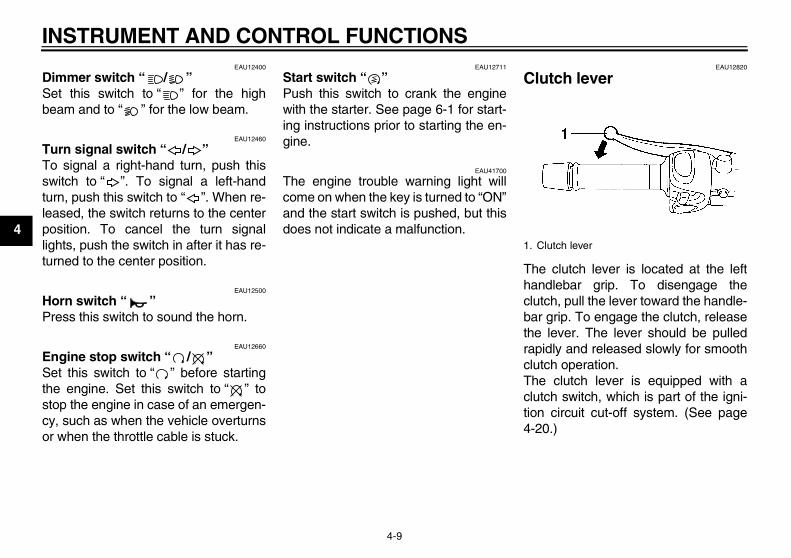
Self-diagnosis device
This model is equipped with a self-diag-nosis device for various electrical cir-cuits.If a problem is detected in any of thosecircuits, the engine trouble warning lightwill come on and the display will indi-cate an error code.The self-diagnosis device also detectsproblems in the immobilizer system cir-cuits.If the display indicates any error codes,note the code number, and then have aYamaha dealer check the vehicle.
NOTICEECA11590
If the display indicates an errorcode, the vehicle should be checkedas soon as possible in order to avoidengine damage.
EAU12348
Handlebar switches
Left
Right
1. Error code display
1
1. Dimmer switch “ / ”2. Turn signal switch “ / ”3. Horn switch “ ”
1. Engine stop switch “ / ”2. Start switch “ ”
1
23
U36P10E0.book Page 8 Thursday, November 13, 2008 4:45 PM
INSTRUMENT AND CONTROL FUNCTIONS
4-9
4
EAU12400
Dimmer switch “ / ” Set this switch to “ ” for the highbeam and to “ ” for the low beam.
EAU12460
Turn signal switch “ / ” To signal a right-hand turn, push thisswitch to “ ”. To signal a left-handturn, push this switch to “ ”. When re-leased, the switch returns to the centerposition. To cancel the turn signallights, push the switch in after it has re-turned to the center position.
EAU12500
Horn switch “ ” Press this switch to sound the horn.
EAU12660
Engine stop switch “ / ” Set this switch to “ ” before startingthe engine. Set this switch to “ ” tostop the engine in case of an emergen-cy, such as when the vehicle overturnsor when the throttle cable is stuck.
EAU12711
Start switch “ ” Push this switch to crank the enginewith the starter. See page 6-1 for start-ing instructions prior to starting the en-gine.
EAU41700
The engine trouble warning light willcome on when the key is turned to “ON”and the start switch is pushed, but thisdoes not indicate a malfunction.
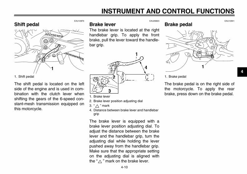
EAU12820
Clutch lever
The clutch lever is located at the lefthandlebar grip. To disengage theclutch, pull the lever toward the handle-bar grip. To engage the clutch, releasethe lever. The lever should be pulledrapidly and released slowly for smoothclutch operation.The clutch lever is equipped with aclutch switch, which is part of the igni-tion circuit cut-off system. (See page4-20.)
1. Clutch lever
U36P10E0.book Page 9 Thursday, November 13, 2008 4:45 PM
INSTRUMENT AND CONTROL FUNCTIONS
4-10
4
EAU12870
Shift pedal
The shift pedal is located on the leftside of the engine and is used in com-bination with the clutch lever whenshifting the gears of the 6-speed con-stant-mesh transmission equipped onthis motorcycle.
EAU26823
Brake lever The brake lever is located at the righthandlebar grip. To apply the frontbrake, pull the lever toward the handle-bar grip.
The brake lever is equipped with abrake lever position adjusting dial. Toadjust the distance between the brakelever and the handlebar grip, turn theadjusting dial while holding the leverpushed away from the handlebar grip.Make sure that the appropriate settingon the adjusting dial is aligned withthe “ ” mark on the brake lever.
EAU12941
Brake pedal
The brake pedal is on the right side ofthe motorcycle. To apply the rearbrake, press down on the brake pedal.
1. Shift pedal
1
1. Brake lever2. Brake lever position adjusting dial3. “ ” mark4. Distance between brake lever and handlebar
grip
1. Brake pedal
1
U36P10E0.book Page 10 Thursday, November 13, 2008 4:45 PM
INSTRUMENT AND CONTROL FUNCTIONS
4-11
4
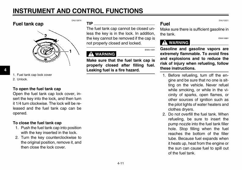
EAU13074
Fuel tank cap
To open the fuel tank capOpen the fuel tank cap lock cover, in-sert the key into the lock, and then turnit 1/4 turn clockwise. The lock will be re-leased and the fuel tank cap can beopened.
To close the fuel tank cap1. Push the fuel tank cap into position
with the key inserted in the lock.2. Turn the key counterclockwise to
the original position, remove it, andthen close the lock cover.
TIPThe fuel tank cap cannot be closed un-less the key is in the lock. In addition,the key cannot be removed if the cap isnot properly closed and locked.
WARNINGEWA11091
Make sure that the fuel tank cap isproperly closed after filling fuel.Leaking fuel is a fire hazard.
EAU13221
Fuel Make sure there is sufficient gasoline inthe tank.
WARNINGEWA10881
Gasoline and gasoline vapors areextremely flammable. To avoid firesand explosions and to reduce therisk of injury when refueling, followthese instructions.
1. Before refueling, turn off the en-gine and be sure that no one is sit-ting on the vehicle. Never refuelwhile smoking, or while in the vi-cinity of sparks, open flames, orother sources of ignition such asthe pilot lights of water heaters andclothes dryers.
2. Do not overfill the fuel tank. Whenrefueling, be sure to insert thepump nozzle into the fuel tank fillerhole. Stop filling when the fuelreaches the bottom of the fillertube. Because fuel expands whenit heats up, heat from the engine orthe sun can cause fuel to spill outof the fuel tank.
1. Fuel tank cap lock cover2. Unlock.
U36P10E0.book Page 11 Thursday, November 13, 2008 4:45 PM
INSTRUMENT AND CONTROL FUNCTIONS
4-12
4
3. Wipe up any spilled fuel immedi-ately. NOTICE: Immediately wipeoff spilled fuel with a clean, dry,soft cloth, since fuel may deteri-orate painted surfaces or plasticparts. [ECA10071]
4. Be sure to securely close the fueltank cap.
WARNINGEWA15151
Gasoline is poisonous and cancause injury or death. Handle gaso-line with care. Never siphon gaso-line by mouth. If you should swallowsome gasoline or inhale a lot of gas-oline vapor, or get some gasoline inyour eyes, see your doctor immedi-
ately. If gasoline spills on your skin,wash with soap and water. If gaso-line spills on your clothing, changeyour clothes.
EAU13301
NOTICEECA11400
Use only unleaded gasoline. The useof leaded gasoline will cause severedamage to internal engine parts,such as the valves and piston rings,as well as to the exhaust system.
Your Yamaha engine has been de-signed to use regular unleaded gaso-line with a pump octane number[(R+M)/2] of 86 or higher, or a researchoctane number of 91 or higher. Ifknocking (or pinging) occurs, use agasoline of a different brand or premi-
um unleaded fuel. Use of unleaded fuelwill extend spark plug life and reducemaintenance costs.GasoholThere are two types of gasohol: gaso-hol containing ethanol and that contain-ing methanol. Gasohol containingethanol can be used if the ethanol con-tent does not exceed 10% (E10). Gas-ohol containing methanol is notrecommended by Yamaha because itcan cause damage to the fuel systemor vehicle performance problems.
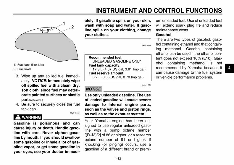
1. Fuel tank filler tube2. Fuel level
12
Recommended fuel:UNLEADED GASOLINE ONLY
Fuel tank capacity:17.3 L (4.57 US gal, 3.81 Imp.gal)
Fuel reserve amount:3.2 L (0.85 US gal, 0.70 Imp.gal)
U36P10E0.book Page 12 Thursday, November 13, 2008 4:45 PM
INSTRUMENT AND CONTROL FUNCTIONS
4-13
4
EAU13433
Catalytic converter This model is equipped with a catalyticconverter in the exhaust system.
WARNINGEWA10862
The exhaust system is hot after op-eration. To prevent a fire hazard orburns:
� Do not park the vehicle nearpossible fire hazards such asgrass or other materials thateasily burn.
� Park the vehicle in a placewhere pedestrians or childrenare not likely to touch the hotexhaust system.
� Make sure that the exhaust sys-tem has cooled down before do-ing any maintenance work.
� Do not allow the engine to idlemore than a few minutes. Longidling can cause a build-up ofheat.
NOTICEECA10701
Use only unleaded gasoline. The useof leaded gasoline will cause unre-pairable damage to the catalyticconverter.
EAU47360
Seats
Passenger seat
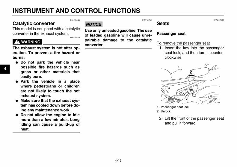
To remove the passenger seat1. Insert the key into the passenger
seat lock, and then turn it counter-clockwise.
2. Lift the front of the passenger seatand pull it forward.
1. Passenger seat lock2. Unlock.
1
2
U36P10E0.book Page 13 Thursday, November 13, 2008 4:45 PM
INSTRUMENT AND CONTROL FUNCTIONS
4-14
4
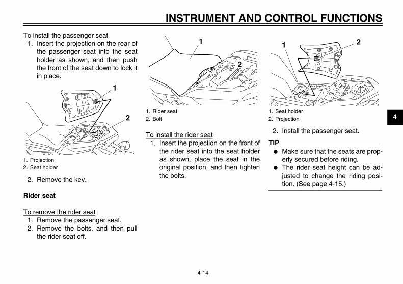
To install the passenger seat1. Insert the projection on the rear of
the passenger seat into the seatholder as shown, and then pushthe front of the seat down to lock itin place.
2. Remove the key.
Rider seat
To remove the rider seat1. Remove the passenger seat.2. Remove the bolts, and then pull
the rider seat off.
To install the rider seat1. Insert the projection on the front of
the rider seat into the seat holderas shown, place the seat in theoriginal position, and then tightenthe bolts.
2. Install the passenger seat.
TIP� Make sure that the seats are prop-
erly secured before riding.� The rider seat height can be ad-
justed to change the riding posi-tion. (See page 4-15.)
1. Projection2. Seat holder
1
21. Rider seat2. Bolt
1
2
1. Seat holder2. Projection
1 2
U36P10E0.book Page 14 Thursday, November 13, 2008 4:45 PM
INSTRUMENT AND CONTROL FUNCTIONS
4-15
4
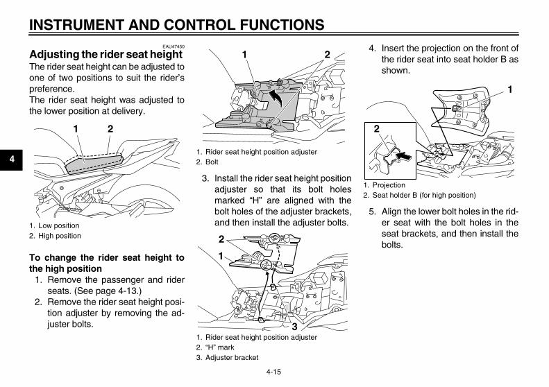
EAU47450
Adjusting the rider seat height The rider seat height can be adjusted toone of two positions to suit the rider’spreference.The rider seat height was adjusted tothe lower position at delivery.
To change the rider seat height tothe high position
1. Remove the passenger and riderseats. (See page 4-13.)
2. Remove the rider seat height posi-tion adjuster by removing the ad-juster bolts.
3. Install the rider seat height positionadjuster so that its bolt holesmarked “H” are aligned with thebolt holes of the adjuster brackets,and then install the adjuster bolts.
4. Insert the projection on the front ofthe rider seat into seat holder B asshown.
5. Align the lower bolt holes in the rid-er seat with the bolt holes in theseat brackets, and then install thebolts.
1. Low position2. High position
1 2
1. Rider seat height position adjuster2. Bolt
1. Rider seat height position adjuster2. “H” mark3. Adjuster bracket
1 2
1
3
2
1. Projection2. Seat holder B (for high position)
2
1
U36P10E0.book Page 15 Thursday, November 13, 2008 4:45 PM
INSTRUMENT AND CONTROL FUNCTIONS
4-16
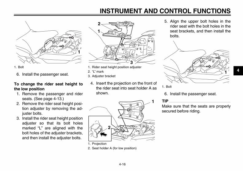
46. Install the passenger seat.
To change the rider seat height tothe low position
1. Remove the passenger and riderseats. (See page 4-13.)
2. Remove the rider seat height posi-tion adjuster by removing the ad-juster bolts.
3. Install the rider seat height positionadjuster so that its bolt holesmarked “L” are aligned with thebolt holes of the adjuster brackets,and then install the adjuster bolts.
4. Insert the projection on the front ofthe rider seat into seat holder A asshown.
5. Align the upper bolt holes in therider seat with the bolt holes in theseat brackets, and then install thebolts.
6. Install the passenger seat.
TIPMake sure that the seats are properlysecured before riding.
1. Bolt
1
1. Rider seat height position adjuster2. “L” mark3. Adjuster bracket
1. Projection2. Seat holder A (for low position)
1
3
2
2
1
1. Bolt
1
U36P10E0.book Page 16 Thursday, November 13, 2008 4:45 PM
INSTRUMENT AND CONTROL FUNCTIONS
4-17
4
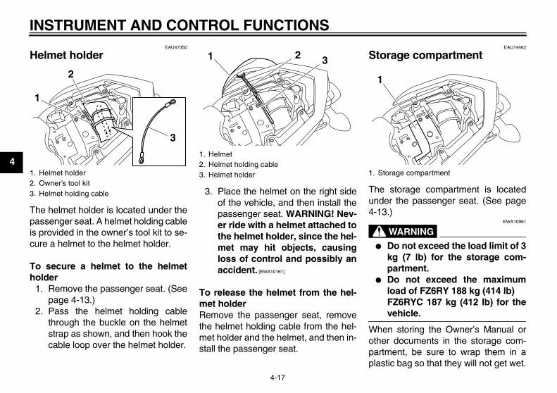
EAU47350
Helmet holder
The helmet holder is located under thepassenger seat. A helmet holding cableis provided in the owner’s tool kit to se-cure a helmet to the helmet holder.
To secure a helmet to the helmetholder
1. Remove the passenger seat. (Seepage 4-13.)
2. Pass the helmet holding cablethrough the buckle on the helmetstrap as shown, and then hook thecable loop over the helmet holder.
3. Place the helmet on the right sideof the vehicle, and then install thepassenger seat. WARNING! Nev-er ride with a helmet attached tothe helmet holder, since the hel-met may hit objects, causingloss of control and possibly anaccident. [EWA10161]
To release the helmet from the hel-met holderRemove the passenger seat, removethe helmet holding cable from the hel-met holder and the helmet, and then in-stall the passenger seat.
EAU14462
Storage compartment
The storage compartment is locatedunder the passenger seat. (See page4-13.)
WARNINGEWA10961
� Do not exceed the load limit of 3kg (7 lb) for the storage com-partment.
� Do not exceed the maximumload of FZ6RY 188 kg (414 lb)FZ6RYC 187 kg (412 lb) for thevehicle.
When storing the Owner’s Manual orother documents in the storage com-partment, be sure to wrap them in aplastic bag so that they will not get wet.
1. Helmet holder2. Owner’s tool kit3. Helmet holding cable
3
1
2
1. Helmet2. Helmet holding cable3. Helmet holder
1 2 3
1. Storage compartment
1
U36P10E0.book Page 17 Thursday, November 13, 2008 4:45 PM
INSTRUMENT AND CONTROL FUNCTIONS
4-18
4
When washing the vehicle, be carefulnot to let any water enter the storagecompartment.
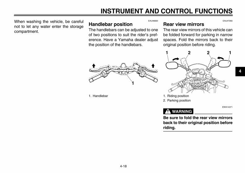
EAU46830
Handlebar position The handlebars can be adjusted to oneof two positions to suit the rider’s pref-erence. Have a Yamaha dealer adjustthe position of the handlebars.
EAU47260
Rear view mirrors The rear view mirrors of this vehicle canbe folded forward for parking in narrowspaces. Fold the mirrors back to theiroriginal position before riding.
WARNINGEWA14371
Be sure to fold the rear view mirrorsback to their original position beforeriding.
1. Handlebar
1
1. Riding position2. Parking position
1 2 12
U36P10E0.book Page 18 Thursday, November 13, 2008 4:45 PM
INSTRUMENT AND CONTROL FUNCTIONS
4-19
4
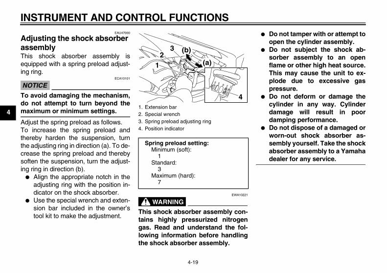
EAU47000
Adjusting the shock absorber assembly This shock absorber assembly isequipped with a spring preload adjust-ing ring.
NOTICEECA10101
To avoid damaging the mechanism,do not attempt to turn beyond themaximum or minimum settings.
Adjust the spring preload as follows.To increase the spring preload andthereby harden the suspension, turnthe adjusting ring in direction (a). To de-crease the spring preload and therebysoften the suspension, turn the adjust-ing ring in direction (b).
� Align the appropriate notch in theadjusting ring with the position in-dicator on the shock absorber.
� Use the special wrench and exten-sion bar included in the owner’stool kit to make the adjustment.
WARNINGEWA10221
This shock absorber assembly con-tains highly pressurized nitrogengas. Read and understand the fol-lowing information before handlingthe shock absorber assembly.
� Do not tamper with or attempt toopen the cylinder assembly.
� Do not subject the shock ab-sorber assembly to an openflame or other high heat source.This may cause the unit to ex-plode due to excessive gaspressure.
� Do not deform or damage thecylinder in any way. Cylinderdamage will result in poordamping performance.
� Do not dispose of a damaged orworn-out shock absorber as-sembly yourself. Take the shockabsorber assembly to a Yamahadealer for any service.
1. Extension bar2. Special wrench3. Spring preload adjusting ring4. Position indicator
Spring preload setting:Minimum (soft):
1Standard:
3Maximum (hard):
7
12
3
(a)
(b)
4
U36P10E0.book Page 19 Thursday, November 13, 2008 4:45 PM
INSTRUMENT AND CONTROL FUNCTIONS
4-20
4
EAU15301
Sidestand The sidestand is located on the left sideof the frame. Raise the sidestand orlower it with your foot while holding thevehicle upright.
TIPThe built-in sidestand switch is part ofthe ignition circuit cut-off system, whichcuts the ignition in certain situations.(See further down for an explanation ofthe ignition circuit cut-off system.)
WARNINGEWA10240
The vehicle must not be ridden withthe sidestand down, or if the side-stand cannot be properly moved up(or does not stay up), otherwise thesidestand could contact the groundand distract the operator, resultingin a possible loss of control.Yamaha’s ignition circuit cut-offsystem has been designed to assistthe operator in fulfilling the respon-sibility of raising the sidestand be-fore starting off. Therefore, checkthis system regularly as described
below and have a Yamaha dealer re-pair it if it does not function proper-ly.
EAU44892
Ignition circuit cut-off system The ignition circuit cut-off system (com-prising the sidestand switch, clutchswitch and neutral switch) has the fol-lowing functions.
� It prevents starting when the trans-mission is in gear and the side-stand is up, but the clutch lever isnot pulled.
� It prevents starting when the trans-mission is in gear and the clutch le-ver is pulled, but the sidestand isstill down.
� It cuts the running engine when thetransmission is in gear and the sid-estand is moved down.
Periodically check the operation of theignition circuit cut-off system accordingto the following procedure.
U36P10E0.book Page 20 Thursday, November 13, 2008 4:45 PM
INSTRUMENT AND CONTROL FUNCTIONS
4-21
4
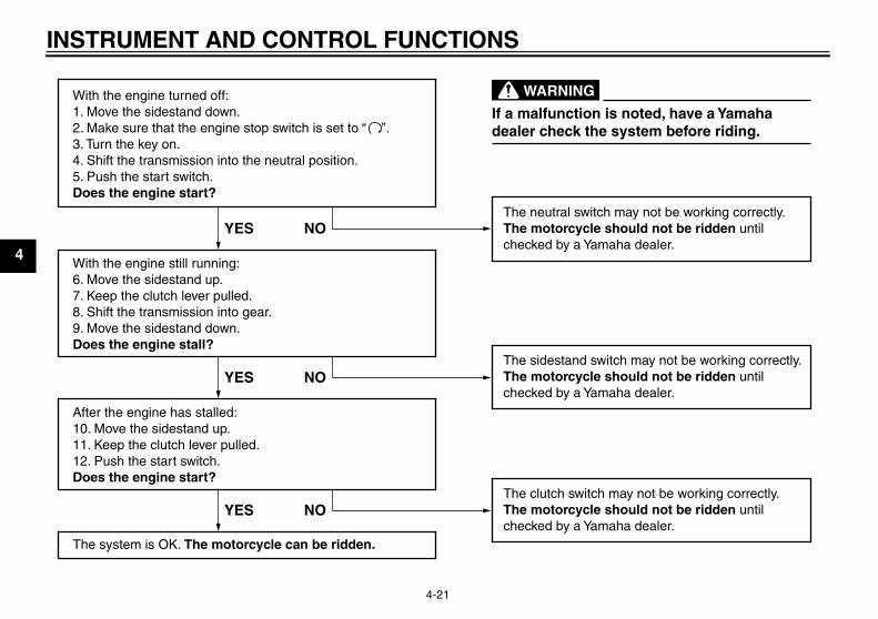
With the engine turned off:1. Move the sidestand down.2. Make sure that the engine stop switch is set to “3. Turn the key on. 4. Shift the transmission into the neutral position.5. Push the start switch.Does the engine start?
With the engine still running:6. Move the sidestand up.7. Keep the clutch lever pulled.8. Shift the transmission into gear.9. Move the sidestand down.Does the engine stall?
After the engine has stalled:10. Move the sidestand up.11. Keep the clutch lever pulled.12. Push the start switch.Does the engine start?
The system is OK. The motorcycle can be ridden.
The neutral switch may not be working correctly.The motorcycle should not be ridden untilchecked by a Yamaha dealer.
The sidestand switch may not be working correctly.The motorcycle should not be ridden untilchecked by a Yamaha dealer.
The clutch switch may not be working correctly.The motorcycle should not be ridden untilchecked by a Yamaha dealer.
YES NO
YES NO
YES NO
If a malfunction is noted, have a Yamahadealer check the system before riding.
WARNING
”.
U36P10E0.book Page 21 Thursday, November 13, 2008 4:45 PM
FOR YOUR SAFETY – PRE-OPERATION CHECKS
5-1
5
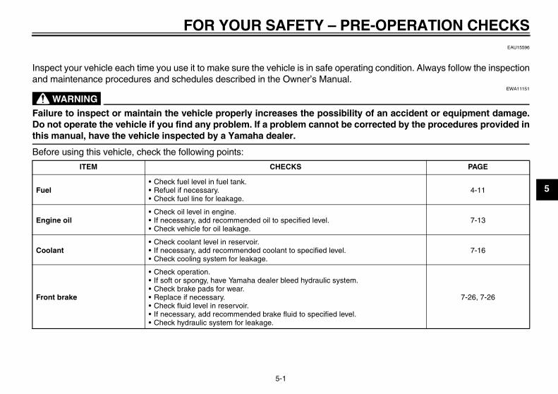
EAU15596
Inspect your vehicle each time you use it to make sure the vehicle is in safe operating condition. Always follow the inspectionand maintenance procedures and schedules described in the Owner’s Manual.
WARNINGEWA11151
Failure to inspect or maintain the vehicle properly increases the possibility of an accident or equipment damage.Do not operate the vehicle if you find any problem. If a problem cannot be corrected by the procedures provided inthis manual, have the vehicle inspected by a Yamaha dealer.
Before using this vehicle, check the following points:
ITEM CHECKS PAGE
Fuel• Check fuel level in fuel tank.• Refuel if necessary.• Check fuel line for leakage.
4-11
Engine oil• Check oil level in engine.• If necessary, add recommended oil to specified level.• Check vehicle for oil leakage.
7-13
Coolant• Check coolant level in reservoir.• If necessary, add recommended coolant to specified level.• Check cooling system for leakage.
7-16
Front brake
• Check operation.• If soft or spongy, have Yamaha dealer bleed hydraulic system.• Check brake pads for wear.• Replace if necessary.• Check fluid level in reservoir.• If necessary, add recommended brake fluid to specified level.• Check hydraulic system for leakage.
7-26, 7-26
U36P10E0.book Page 1 Thursday, November 13, 2008 4:45 PM
FOR YOUR SAFETY – PRE-OPERATION CHECKS
5-2
5
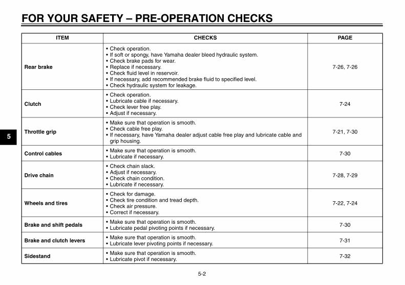
Rear brake
• Check operation.• If soft or spongy, have Yamaha dealer bleed hydraulic system.• Check brake pads for wear.• Replace if necessary.• Check fluid level in reservoir.• If necessary, add recommended brake fluid to specified level.• Check hydraulic system for leakage.
7-26, 7-26
Clutch
• Check operation.• Lubricate cable if necessary.• Check lever free play.• Adjust if necessary.
7-24
Throttle grip
• Make sure that operation is smooth.• Check cable free play.• If necessary, have Yamaha dealer adjust cable free play and lubricate cable and
grip housing.
7-21, 7-30
Control cables • Make sure that operation is smooth.• Lubricate if necessary. 7-30
Drive chain
• Check chain slack.• Adjust if necessary.• Check chain condition.• Lubricate if necessary.
7-28, 7-29
Wheels and tires
• Check for damage.• Check tire condition and tread depth.• Check air pressure.• Correct if necessary.
7-22, 7-24
Brake and shift pedals • Make sure that operation is smooth.• Lubricate pedal pivoting points if necessary. 7-30
Brake and clutch levers • Make sure that operation is smooth.• Lubricate lever pivoting points if necessary. 7-31
Sidestand • Make sure that operation is smooth.• Lubricate pivot if necessary. 7-32
ITEM CHECKS PAGE
U36P10E0.book Page 2 Thursday, November 13, 2008 4:45 PM
FOR YOUR SAFETY – PRE-OPERATION CHECKS
5-3
5
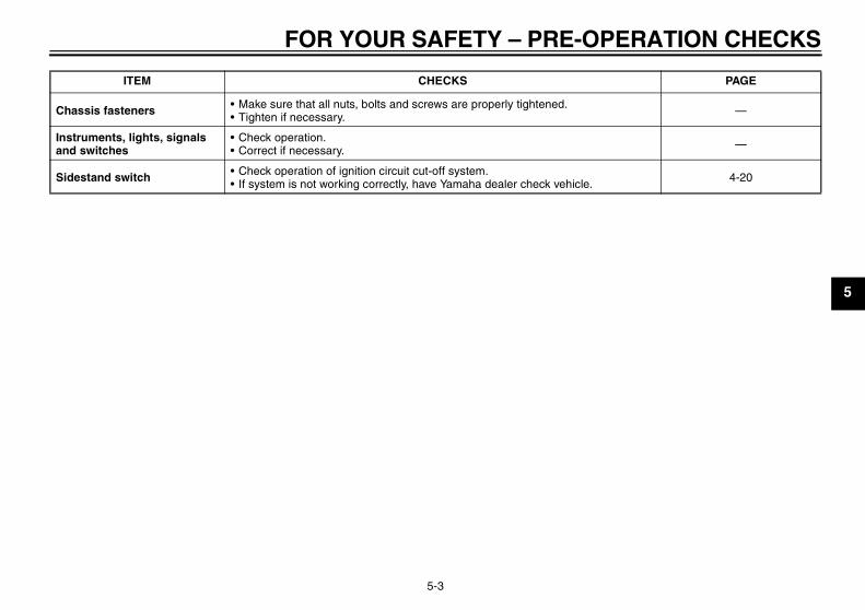
Chassis fasteners • Make sure that all nuts, bolts and screws are properly tightened.• Tighten if necessary. —
Instruments, lights, signals and switches
• Check operation.• Correct if necessary. —
Sidestand switch • Check operation of ignition circuit cut-off system.• If system is not working correctly, have Yamaha dealer check vehicle. 4-20
ITEM CHECKS PAGE
U36P10E0.book Page 3 Thursday, November 13, 2008 4:45 PM
OPERATION AND IMPORTANT RIDING POINTS
6-1
6
EAU15951
Read the Owner’s Manual carefully tobecome familiar with all controls. Ifthere is a control or function you do notunderstand, ask your Yamaha dealer.
WARNINGEWA10271
Failure to familiarize yourself withthe controls can lead to loss of con-trol, which could cause an accidentor injury.
EAU46632
TIPThis model is equipped with:
� a lean angle sensor to stop the en-gine in case of a turnover. In thiscase, the multi-function display in-dicates error code 30, but this isnot a malfunction. Turn the key to“OFF” and then to “ON” to clear theerror code. Failing to do so will pre-vent the engine from starting eventhough the engine will crank whenpushing the start switch.
� an engine auto-stop system. Theengine stops automatically if leftidling for 20 minutes. In this case,the multi-function display indicateserror code 70, but this is not a mal-function. Push the start switch toclear the error code and to restartthe engine.
EAU40197
Starting the engine In order for the ignition circuit cut-offsystem to enable starting, one of thefollowing conditions must be met.
� The transmission is in the neutralposition.
� The transmission is in gear withthe clutch lever pulled and the sid-estand up.See page 4-20 for more informa-tion.
1. Turn the key to “ON” and makesure that the engine stop switch isset to “ ”.The following warning lightsshould come on for a few seconds,then go off.
� Oil level warning light� Coolant temperature warning
light� Engine trouble warning light
NOTICEECA15482
If a warning light does not go off, seepage 4-2 for the correspondingwarning light circuit check.
U36P10E0.book Page 1 Thursday, November 13, 2008 4:45 PM
OPERATION AND IMPORTANT RIDING POINTS
6-2
6
2. Shift the transmission into the neu-tral position. (See page 6-2.) Theneutral indicator light should comeon. If not, ask a Yamaha dealer tocheck the electrical circuit.
3. Start the engine by pushing thestart switch. NOTICE: For maxi-mum engine life, never acceler-ate hard when the engine iscold! [ECA11041]
If the engine fails to start, releasethe start switch, wait a few sec-onds, and then try again. Eachstarting attempt should be as shortas possible to preserve the bat-tery. Do not crank the engine morethan 10 seconds on any one at-tempt.
EAU16671
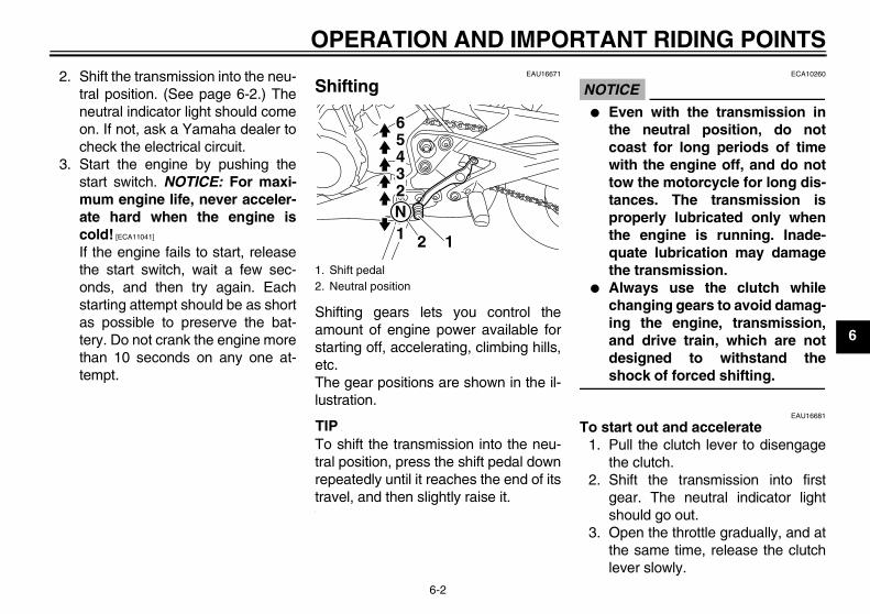
Shifting
Shifting gears lets you control theamount of engine power available forstarting off, accelerating, climbing hills,etc.The gear positions are shown in the il-lustration.
TIPTo shift the transmission into the neu-tral position, press the shift pedal downrepeatedly until it reaches the end of itstravel, and then slightly raise it.
NOTICEECA10260
� Even with the transmission inthe neutral position, do notcoast for long periods of timewith the engine off, and do nottow the motorcycle for long dis-tances. The transmission isproperly lubricated only whenthe engine is running. Inade-quate lubrication may damagethe transmission.
� Always use the clutch whilechanging gears to avoid damag-ing the engine, transmission,and drive train, which are notdesigned to withstand theshock of forced shifting.
EAU16681
To start out and accelerate1. Pull the clutch lever to disengage
the clutch.2. Shift the transmission into first
gear. The neutral indicator lightshould go out.
3. Open the throttle gradually, and atthe same time, release the clutchlever slowly.
1. Shift pedal2. Neutral position
1N23456
12
U36P10E0.book Page 2 Thursday, November 13, 2008 4:45 PM
OPERATION AND IMPORTANT RIDING POINTS
6-3
6
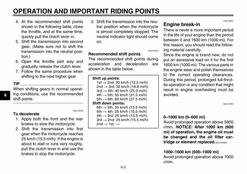
4. At the recommended shift pointsshown in the following table, closethe throttle, and at the same time,quickly pull the clutch lever in.
5. Shift the transmission into secondgear. (Make sure not to shift thetransmission into the neutral posi-tion.)
6. Open the throttle part way andgradually release the clutch lever.
7. Follow the same procedure whenshifting to the next higher gear.
TIPWhen shifting gears in normal operat-ing conditions, use the recommendedshift points.
EAU16700
To decelerate1. Apply both the front and the rear
brakes to slow the motorcycle.2. Shift the transmission into first
gear when the motorcycle reaches25 km/h (15.5 mi/h). If the engine isabout to stall or runs very roughly,pull the clutch lever in and use thebrakes to stop the motorcycle.
3. Shift the transmission into the neu-tral position when the motorcycleis almost completely stopped. Theneutral indicator light should comeon.
EAU16740
Recommended shift pointsThe recommended shift points duringacceleration and deceleration areshown in the table below.
EAU16841
Engine break-in There is never a more important periodin the life of your engine than the periodbetween 0 and 1600 km (1000 mi). Forthis reason, you should read the follow-ing material carefully.Since the engine is brand new, do notput an excessive load on it for the first1600 km (1000 mi). The various parts inthe engine wear and polish themselvesto the correct operating clearances.During this period, prolonged full-throt-tle operation or any condition that mightresult in engine overheating must beavoided.
EAU17093
0–1000 km (0–600 mi)Avoid prolonged operation above 5800r/min. NOTICE: After 1000 km (600mi) of operation, the engine oil mustbe changed and the oil filter car-tridge or element replaced. [ECA10302]
1000–1600 km (600–1000 mi)Avoid prolonged operation above 7000r/min.
Shift up points:1st → 2nd: 20 km/h (12.5 mi/h)2nd → 3rd: 30 km/h (18.8 mi/h)3rd → 4th: 40 km/h (25.0 mi/h)4th → 5th: 50 km/h (31.3 mi/h)5th → 6th: 60 km/h (37.5 mi/h)
Shift down points:6th → 5th: 25 km/h (15.5 mi/h)5th → 4th: 25 km/h (15.5 mi/h)4th → 3rd: 25 km/h (15.5 mi/h)3rd → 2nd: 25 km/h (15.5 mi/h)2nd → 1st: —
U36P10E0.book Page 3 Thursday, November 13, 2008 4:45 PM
OPERATION AND IMPORTANT RIDING POINTS
6-4
6
1600 km (1000 mi) and beyondThe vehicle can now be operated nor-mally.
NOTICEECA10310
� Keep the engine speed out ofthe tachometer red zone.
� If any engine trouble should oc-cur during the engine break-inperiod, immediately have aYamaha dealer check the vehi-cle.
EAU17213
Parking When parking, stop the engine, andthen remove the key from the mainswitch.
WARNINGEWA10311
� Since the engine and exhaustsystem can become very hot,park in a place where pedestri-ans or children are not likely totouch them and be burned.
� Do not park on a slope or on softground, otherwise the vehiclemay overturn, increasing therisk of a fuel leak and fire.
� Do not park near grass or otherflammable materials whichmight catch fire.
U36P10E0.book Page 4 Thursday, November 13, 2008 4:45 PM
PERIODIC MAINTENANCE AND ADJUSTMENT
7-1
7
EAU17232
Periodic inspection, adjustment, and lu-brication will keep your vehicle in thesafest and most efficient condition pos-sible. Safety is an obligation of the vehi-cle owner/operator. The most importantpoints of vehicle inspection, adjust-ment, and lubrication are explained onthe following pages.
WARNINGEWA10321
Failure to properly maintain the ve-hicle or performing maintenance ac-tivities incorrectly may increaseyour risk of injury or death duringservice or while using the vehicle. Ifyou are not familiar with vehicle ser-vice, have a Yamaha dealer performservice.
WARNINGEWA15121
Turn off the engine when performingmaintenance unless otherwisespecified.
� A running engine has movingparts that can catch on bodyparts or clothing and electricalparts that can cause shocks orfires.
� Running the engine while ser-vicing can lead to eye injury,burns, fire, or carbon monoxidepoisoning – possibly leading todeath. See page 2-1 for more in-formation about carbon monox-ide.
EAU17302
Emission controls not only function toensure cleaner air, but are also vital toproper engine operation and maximumperformance. In the following periodicmaintenance charts, the services relat-ed to emissions control are groupedseparately. These services requirespecialized data, knowledge, andequipment. Maintenance, replacement,or repair of the emission control devic-es and systems may be performed byany repair establishment or individualthat is certified (if applicable). Yamahadealers are trained and equipped toperform these particular services.
U36P10E0.book Page 1 Thursday, November 13, 2008 4:45 PM
PERIODIC MAINTENANCE AND ADJUSTMENT
7-2
7
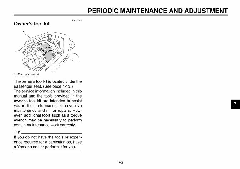
EAU17542
Owner’s tool kit
The owner’s tool kit is located under thepassenger seat. (See page 4-13.)The service information included in thismanual and the tools provided in theowner’s tool kit are intended to assistyou in the performance of preventivemaintenance and minor repairs. How-ever, additional tools such as a torquewrench may be necessary to performcertain maintenance work correctly.
TIPIf you do not have the tools or experi-ence required for a particular job, havea Yamaha dealer perform it for you.
1. Owner’s tool kit
1
U36P10E0.book Page 2 Thursday, November 13, 2008 4:45 PM
PERIODIC MAINTENANCE AND ADJUSTMENT
7-3
7
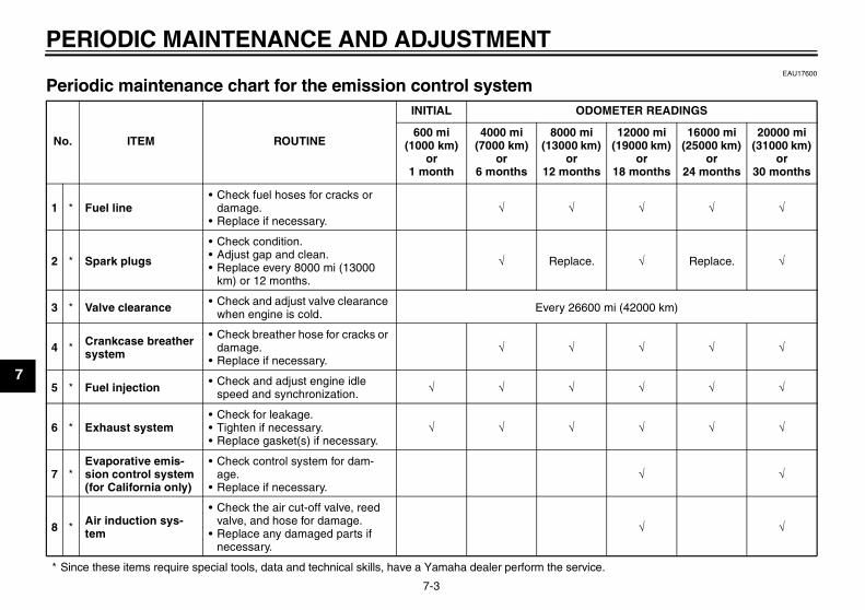
EAU17600
Periodic maintenance chart for the emission control system
* Since these items require special tools, data and technical skills, have a Yamaha dealer perform the service.
No. ITEM ROUTINE
INITIAL ODOMETER READINGS
600 mi (1000 km)
or 1 month
4000 mi (7000 km)
or 6 months
8000 mi (13000 km)
or 12 months
12000 mi (19000 km)
or 18 months
16000 mi (25000 km)
or 24 months
20000 mi (31000 km)
or 30 months
1 * Fuel line• Check fuel hoses for cracks or
damage.• Replace if necessary.
√ √ √ √ √
2 * Spark plugs
• Check condition.• Adjust gap and clean.• Replace every 8000 mi (13000
km) or 12 months.
√ Replace. √ Replace. √
3 * Valve clearance • Check and adjust valve clearance when engine is cold. Every 26600 mi (42000 km)
4 * Crankcase breather system
• Check breather hose for cracks or damage.
• Replace if necessary.√ √ √ √ √
5 * Fuel injection • Check and adjust engine idle speed and synchronization. √ √ √ √ √ √
6 * Exhaust system• Check for leakage.• Tighten if necessary.• Replace gasket(s) if necessary.
√ √ √ √ √ √
7 *Evaporative emis-sion control system (for California only)
• Check control system for dam-age.
• Replace if necessary.√ √
8 * Air induction sys-tem
• Check the air cut-off valve, reed valve, and hose for damage.
• Replace any damaged parts if necessary.
√ √
U36P10E0.book Page 3 Thursday, November 13, 2008 4:45 PM
PERIODIC MAINTENANCE AND ADJUSTMENT
7-4
7
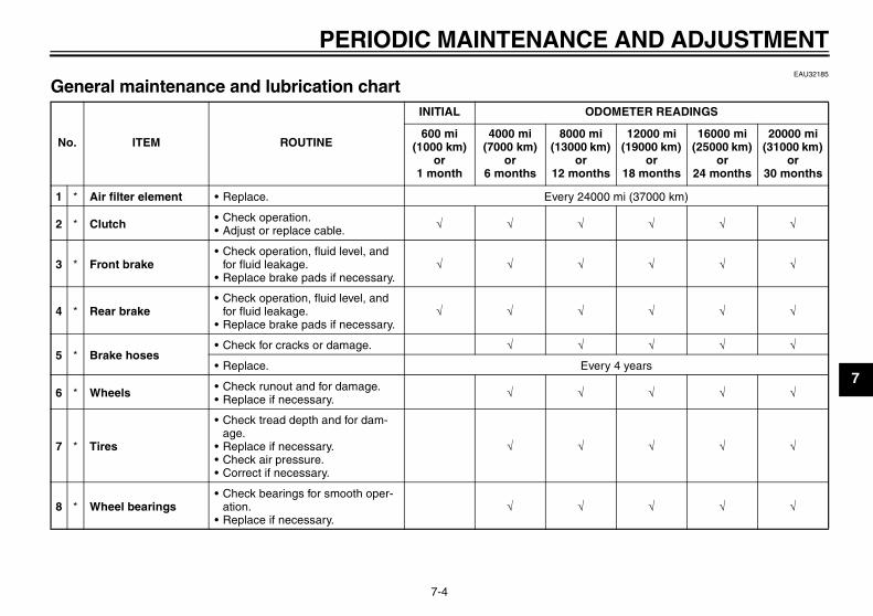
EAU32185
General maintenance and lubrication chart
No. ITEM ROUTINE
INITIAL ODOMETER READINGS
600 mi (1000 km)
or 1 month
4000 mi (7000 km)
or 6 months
8000 mi (13000 km)
or 12 months
12000 mi (19000 km)
or 18 months
16000 mi (25000 km)
or 24 months
20000 mi (31000 km)
or 30 months
1 * Air filter element • Replace. Every 24000 mi (37000 km)
2 * Clutch • Check operation.• Adjust or replace cable. √ √ √ √ √ √
3 * Front brake• Check operation, fluid level, and
for fluid leakage.• Replace brake pads if necessary.
√ √ √ √ √ √
4 * Rear brake• Check operation, fluid level, and
for fluid leakage.• Replace brake pads if necessary.
√ √ √ √ √ √
5 * Brake hoses• Check for cracks or damage. √ √ √ √ √
• Replace. Every 4 years
6 * Wheels • Check runout and for damage.• Replace if necessary. √ √ √ √ √
7 * Tires
• Check tread depth and for dam-age.
• Replace if necessary.• Check air pressure.• Correct if necessary.
√ √ √ √ √
8 * Wheel bearings• Check bearings for smooth oper-
ation.• Replace if necessary.
√ √ √ √ √
U36P10E0.book Page 4 Thursday, November 13, 2008 4:45 PM
PERIODIC MAINTENANCE AND ADJUSTMENT
7-5
7
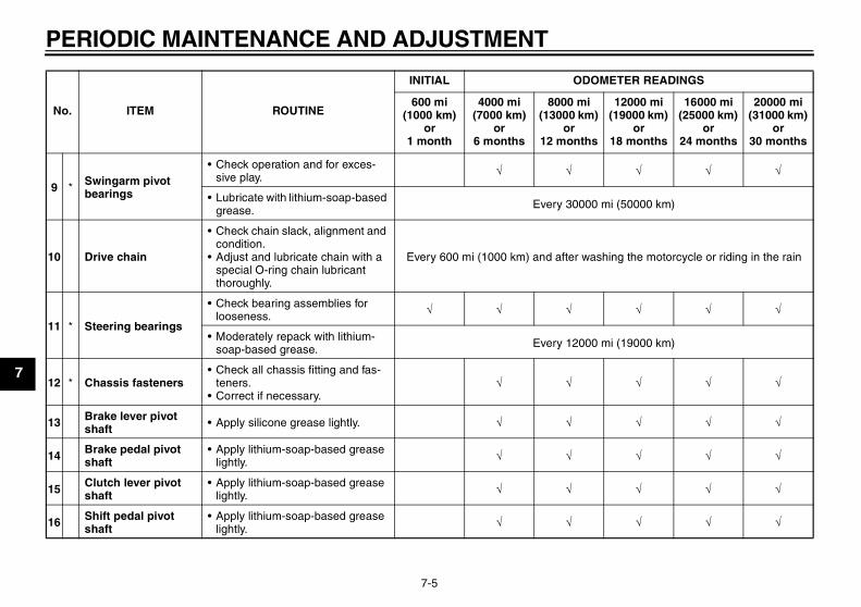
9 * Swingarm pivot bearings
• Check operation and for exces-sive play. √ √ √ √ √
• Lubricate with lithium-soap-based grease. Every 30000 mi (50000 km)
10 Drive chain
• Check chain slack, alignment and condition.
• Adjust and lubricate chain with a special O-ring chain lubricant thoroughly.
Every 600 mi (1000 km) and after washing the motorcycle or riding in the rain
11 * Steering bearings
• Check bearing assemblies for looseness. √ √ √ √ √ √
• Moderately repack with lithium-soap-based grease. Every 12000 mi (19000 km)
12 * Chassis fasteners• Check all chassis fitting and fas-
teners.• Correct if necessary.
√ √ √ √ √
13 Brake lever pivot shaft • Apply silicone grease lightly. √ √ √ √ √
14 Brake pedal pivot shaft
• Apply lithium-soap-based grease lightly. √ √ √ √ √
15 Clutch lever pivot shaft
• Apply lithium-soap-based grease lightly. √ √ √ √ √
16 Shift pedal pivot shaft
• Apply lithium-soap-based grease lightly. √ √ √ √ √
No. ITEM ROUTINE
INITIAL ODOMETER READINGS
600 mi (1000 km)
or 1 month
4000 mi (7000 km)
or 6 months
8000 mi (13000 km)
or 12 months
12000 mi (19000 km)
or 18 months
16000 mi (25000 km)
or 24 months
20000 mi (31000 km)
or 30 months
U36P10E0.book Page 5 Thursday, November 13, 2008 4:45 PM
PERIODIC MAINTENANCE AND ADJUSTMENT
7-6
7
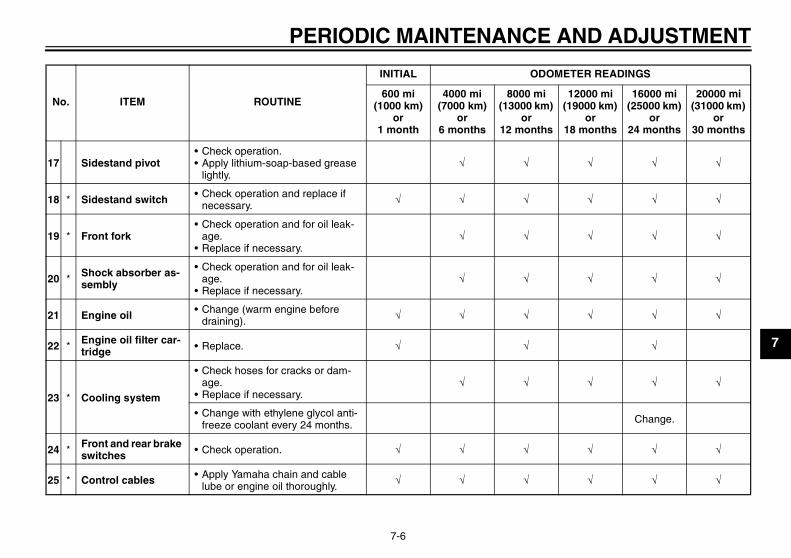
17 Sidestand pivot• Check operation.• Apply lithium-soap-based grease
lightly.√ √ √ √ √
18 * Sidestand switch • Check operation and replace if necessary. √ √ √ √ √ √
19 * Front fork• Check operation and for oil leak-
age.• Replace if necessary.
√ √ √ √ √
20 * Shock absorber as-sembly
• Check operation and for oil leak-age.
• Replace if necessary.√ √ √ √ √
21 Engine oil • Change (warm engine before draining). √ √ √ √ √ √
22 * Engine oil filter car-tridge • Replace. √ √ √
23 * Cooling system
• Check hoses for cracks or dam-age.
• Replace if necessary.√ √ √ √ √
• Change with ethylene glycol anti-freeze coolant every 24 months. Change.
24 * Front and rear brake switches • Check operation. √ √ √ √ √ √
25 * Control cables • Apply Yamaha chain and cable lube or engine oil thoroughly. √ √ √ √ √ √
No. ITEM ROUTINE
INITIAL ODOMETER READINGS
600 mi (1000 km)
or 1 month
4000 mi (7000 km)
or 6 months
8000 mi (13000 km)
or 12 months
12000 mi (19000 km)
or 18 months
16000 mi (25000 km)
or 24 months
20000 mi (31000 km)
or 30 months
U36P10E0.book Page 6 Thursday, November 13, 2008 4:45 PM
PERIODIC MAINTENANCE AND ADJUSTMENT
7-7
7
* Since these items require special tools, data and technical skills, have a Yamaha dealer perform the service.
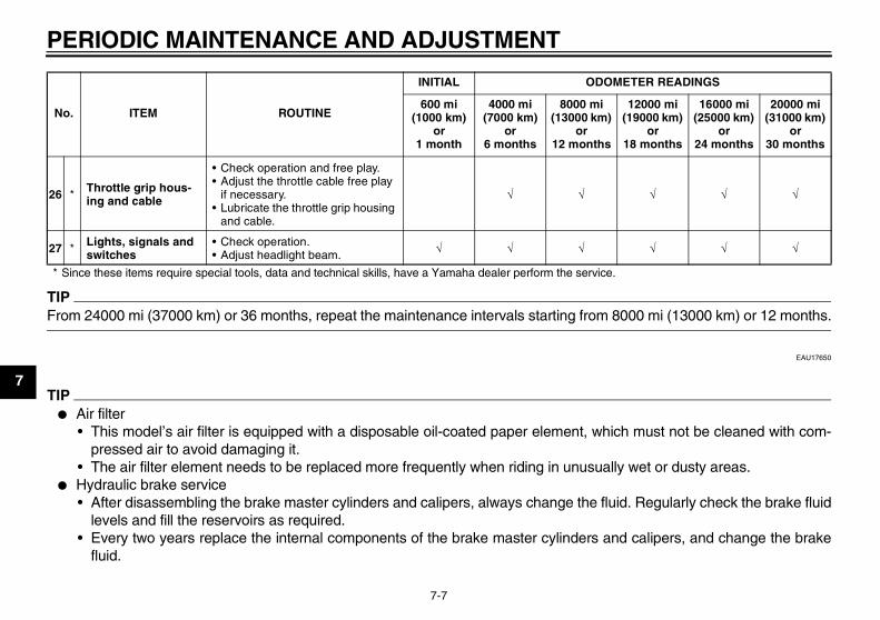
TIPFrom 24000 mi (37000 km) or 36 months, repeat the maintenance intervals starting from 8000 mi (13000 km) or 12 months.
EAU17650
TIP� Air filter
• This model’s air filter is equipped with a disposable oil-coated paper element, which must not be cleaned with com-pressed air to avoid damaging it.
• The air filter element needs to be replaced more frequently when riding in unusually wet or dusty areas.� Hydraulic brake service
• After disassembling the brake master cylinders and calipers, always change the fluid. Regularly check the brake fluidlevels and fill the reservoirs as required.
• Every two years replace the internal components of the brake master cylinders and calipers, and change the brakefluid.
26 * Throttle grip hous-ing and cable
• Check operation and free play.• Adjust the throttle cable free play
if necessary.• Lubricate the throttle grip housing
and cable.
√ √ √ √ √
27 * Lights, signals and switches
• Check operation.• Adjust headlight beam. √ √ √ √ √ √
No. ITEM ROUTINE
INITIAL ODOMETER READINGS
600 mi (1000 km)
or 1 month
4000 mi (7000 km)
or 6 months
8000 mi (13000 km)
or 12 months
12000 mi (19000 km)
or 18 months
16000 mi (25000 km)
or 24 months
20000 mi (31000 km)
or 30 months
U36P10E0.book Page 7 Thursday, November 13, 2008 4:45 PM
PERIODIC MAINTENANCE AND ADJUSTMENT
7-8
7
• Replace the brake hoses every four years and if cracked or damaged.
U36P10E0.book Page 8 Thursday, November 13, 2008 4:45 PM
PERIODIC MAINTENANCE AND ADJUSTMENT
7-9
7
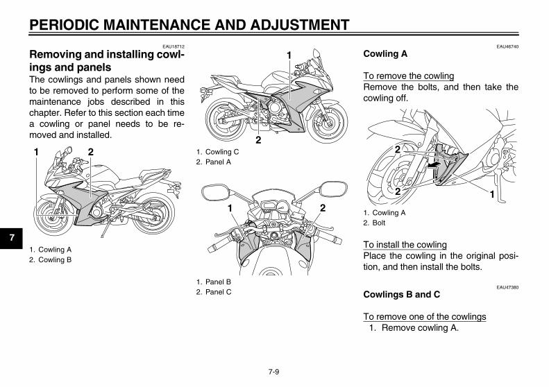
EAU18712
Removing and installing cowl-ings and panels The cowlings and panels shown needto be removed to perform some of themaintenance jobs described in thischapter. Refer to this section each timea cowling or panel needs to be re-moved and installed.
EAU46740
Cowling A
To remove the cowlingRemove the bolts, and then take thecowling off.
To install the cowlingPlace the cowling in the original posi-tion, and then install the bolts.
EAU47380
Cowlings B and C
To remove one of the cowlings1. Remove cowling A.
1. Cowling A2. Cowling B
21 1. Cowling C2. Panel A
1. Panel B2. Panel C
2
1
1 2 1. Cowling A2. Bolt
12
2
U36P10E0.book Page 9 Thursday, November 13, 2008 4:45 PM
PERIODIC MAINTENANCE AND ADJUSTMENT
7-10
7
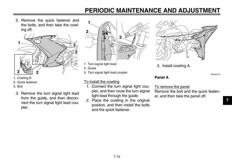
2. Remove the quick fastener andthe bolts, and then take the cowl-ing off.
3. Remove the turn signal light leadfrom the guide, and then discon-nect the turn signal light lead cou-pler.
To install the cowling1. Connect the turn signal light cou-
pler, and then route the turn signallight lead through the guide.
2. Place the cowling in the originalposition, and then install the boltsand the quick fastener.
3. Install cowling A.
EAU46770
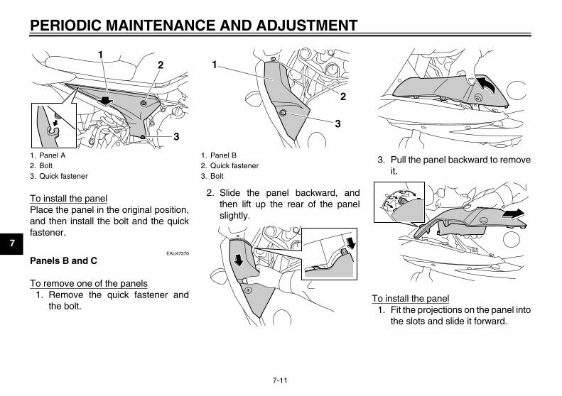
Panel A
To remove the panelRemove the bolt and the quick fasten-er, and then take the panel off.
1. Cowling B2. Quick fastener3. Bolt
3
3
2 2
1
1. Turn signal light lead2. Guide3. Turn signal light lead coupler
1
23
U36P10E0.book Page 10 Thursday, November 13, 2008 4:45 PM
PERIODIC MAINTENANCE AND ADJUSTMENT
7-11
7
To install the panelPlace the panel in the original position,and then install the bolt and the quickfastener.
EAU47370
Panels B and C
To remove one of the panels1. Remove the quick fastener and
the bolt.
2. Slide the panel backward, andthen lift up the rear of the panelslightly.
3. Pull the panel backward to removeit.
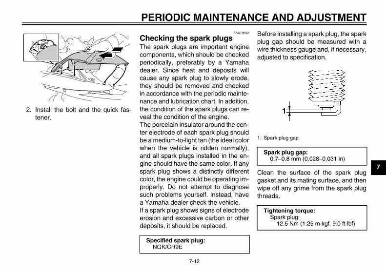
To install the panel1. Fit the projections on the panel into
the slots and slide it forward.
1. Panel A2. Bolt3. Quick fastener
12
3
1. Panel B2. Quick fastener3. Bolt
1
3
2
U36P10E0.book Page 11 Thursday, November 13, 2008 4:45 PM
PERIODIC MAINTENANCE AND ADJUSTMENT
7-12
7
2. Install the bolt and the quick fas-tener.
EAU19642
Checking the spark plugs The spark plugs are important enginecomponents, which should be checkedperiodically, preferably by a Yamahadealer. Since heat and deposits willcause any spark plug to slowly erode,they should be removed and checkedin accordance with the periodic mainte-nance and lubrication chart. In addition,the condition of the spark plugs can re-veal the condition of the engine.The porcelain insulator around the cen-ter electrode of each spark plug shouldbe a medium-to-light tan (the ideal colorwhen the vehicle is ridden normally),and all spark plugs installed in the en-gine should have the same color. If anyspark plug shows a distinctly differentcolor, the engine could be operating im-properly. Do not attempt to diagnosesuch problems yourself. Instead, havea Yamaha dealer check the vehicle.If a spark plug shows signs of electrodeerosion and excessive carbon or otherdeposits, it should be replaced.
Before installing a spark plug, the sparkplug gap should be measured with awire thickness gauge and, if necessary,adjusted to specification.
Clean the surface of the spark pluggasket and its mating surface, and thenwipe off any grime from the spark plugthreads.
Specified spark plug:NGK/CR9E
1. Spark plug gap
Spark plug gap:0.7–0.8 mm (0.028–0.031 in)
Tightening torque:Spark plug:
12.5 Nm (1.25 m·kgf, 9.0 ft·lbf)
U36P10E0.book Page 12 Thursday, November 13, 2008 4:45 PM
PERIODIC MAINTENANCE AND ADJUSTMENT
7-13
7
TIPIf a torque wrench is not available wheninstalling a spark plug, a good estimateof the correct torque is 1/4–1/2 turnpast finger tight. However, the sparkplug should be tightened to the speci-fied torque as soon as possible.
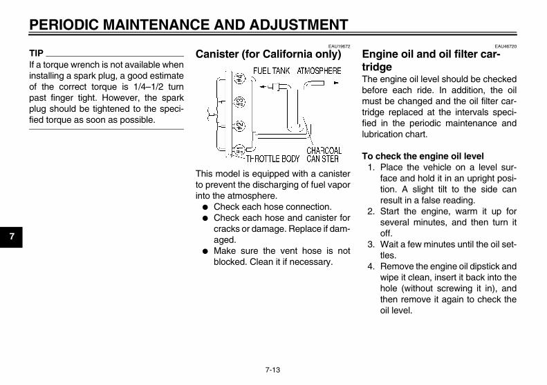
EAU19672
Canister (for California only)
This model is equipped with a canisterto prevent the discharging of fuel vaporinto the atmosphere.
� Check each hose connection.� Check each hose and canister for
cracks or damage. Replace if dam-aged.
� Make sure the vent hose is notblocked. Clean it if necessary.
EAU46720
Engine oil and oil filter car-tridge The engine oil level should be checkedbefore each ride. In addition, the oilmust be changed and the oil filter car-tridge replaced at the intervals speci-fied in the periodic maintenance andlubrication chart.
To check the engine oil level1. Place the vehicle on a level sur-
face and hold it in an upright posi-tion. A slight tilt to the side canresult in a false reading.
2. Start the engine, warm it up forseveral minutes, and then turn itoff.
3. Wait a few minutes until the oil set-tles.
4. Remove the engine oil dipstick andwipe it clean, insert it back into thehole (without screwing it in), andthen remove it again to check theoil level.
U36P10E0.book Page 13 Thursday, November 13, 2008 4:45 PM
PERIODIC MAINTENANCE AND ADJUSTMENT
7-14
7
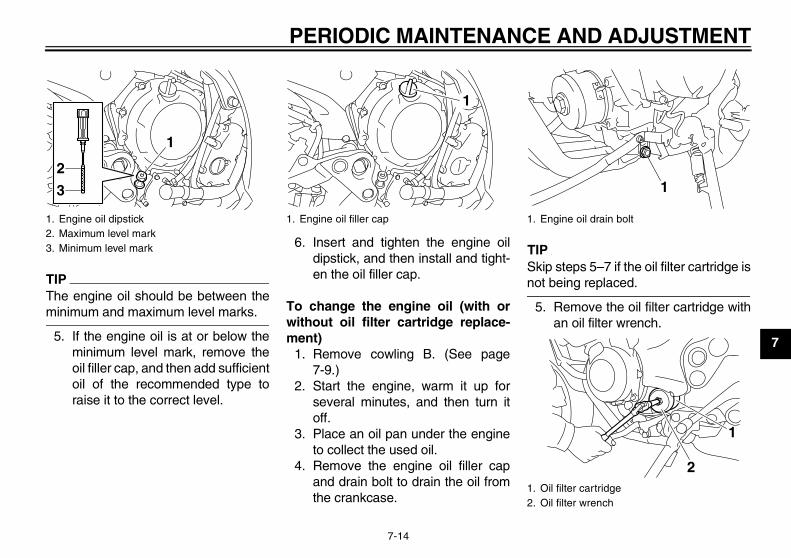
TIPThe engine oil should be between theminimum and maximum level marks.
5. If the engine oil is at or below theminimum level mark, remove theoil filler cap, and then add sufficientoil of the recommended type toraise it to the correct level.
6. Insert and tighten the engine oildipstick, and then install and tight-en the oil filler cap.
To change the engine oil (with orwithout oil filter cartridge replace-ment)
1. Remove cowling B. (See page7-9.)
2. Start the engine, warm it up forseveral minutes, and then turn itoff.
3. Place an oil pan under the engineto collect the used oil.
4. Remove the engine oil filler capand drain bolt to drain the oil fromthe crankcase.
TIPSkip steps 5–7 if the oil filter cartridge isnot being replaced.
5. Remove the oil filter cartridge withan oil filter wrench.
1. Engine oil dipstick2. Maximum level mark3. Minimum level mark
1
2
3
1. Engine oil filler cap
1
1. Engine oil drain bolt
1. Oil filter cartridge2. Oil filter wrench
1
1
2
U36P10E0.book Page 14 Thursday, November 13, 2008 4:45 PM
PERIODIC MAINTENANCE AND ADJUSTMENT
7-15
7
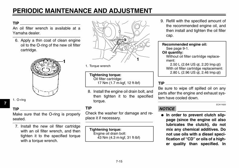
TIPAn oil filter wrench is available at aYamaha dealer.
6. Apply a thin coat of clean engineoil to the O-ring of the new oil filtercartridge.
TIPMake sure that the O-ring is properlyseated.
7. Install the new oil filter cartridgewith an oil filter wrench, and thentighten it to the specified torquewith a torque wrench.
8. Install the engine oil drain bolt, andthen tighten it to the specifiedtorque.
TIPCheck the washer for damage and re-place it if necessary.
9. Refill with the specified amount ofthe recommended engine oil, andthen install and tighten the oil fillercap.
TIPBe sure to wipe off spilled oil on anyparts after the engine and exhaust sys-tem have cooled down.
NOTICEECA11620
� In order to prevent clutch slip-page (since the engine oil alsolubricates the clutch), do notmix any chemical additives. Donot use oils with a diesel speci-fication of “CD” or oils of a high-er quality than specified. In
1. O-ring
1. Torque wrench
Tightening torque:Oil filter cartridge:
17 Nm (1.7 m·kgf, 12 ft·lbf)
Tightening torque:Engine oil drain bolt:
43 Nm (4.3 m·kgf, 31 ft·lbf)
1
Recommended engine oil:See page 9-1.
Oil quantity:Without oil filter cartridge replace-ment:
2.50 L (2.64 US qt, 2.20 Imp.qt)With oil filter cartridge replacement:
2.80 L (2.96 US qt, 2.46 Imp.qt)
U36P10E0.book Page 15 Thursday, November 13, 2008 4:45 PM
PERIODIC MAINTENANCE AND ADJUSTMENT
7-16
7
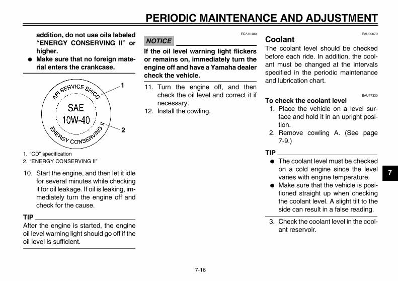
addition, do not use oils labeled“ENERGY CONSERVING II” orhigher.
� Make sure that no foreign mate-rial enters the crankcase.
10. Start the engine, and then let it idlefor several minutes while checkingit for oil leakage. If oil is leaking, im-mediately turn the engine off andcheck for the cause.
TIPAfter the engine is started, the engineoil level warning light should go off if theoil level is sufficient.
NOTICEECA10400
If the oil level warning light flickersor remains on, immediately turn theengine off and have a Yamaha dealercheck the vehicle.
11. Turn the engine off, and thencheck the oil level and correct it ifnecessary.
12. Install the cowling.
EAU20070
Coolant The coolant level should be checkedbefore each ride. In addition, the cool-ant must be changed at the intervalsspecified in the periodic maintenanceand lubrication chart.
EAU47330
To check the coolant level1. Place the vehicle on a level sur-
face and hold it in an upright posi-tion.
2. Remove cowling A. (See page7-9.)
TIP� The coolant level must be checked
on a cold engine since the levelvaries with engine temperature.
� Make sure that the vehicle is posi-tioned straight up when checkingthe coolant level. A slight tilt to theside can result in a false reading.
3. Check the coolant level in the cool-ant reservoir.
1. “CD” specification2. “ENERGY CONSERVING II”
1
2
U36P10E0.book Page 16 Thursday, November 13, 2008 4:45 PM
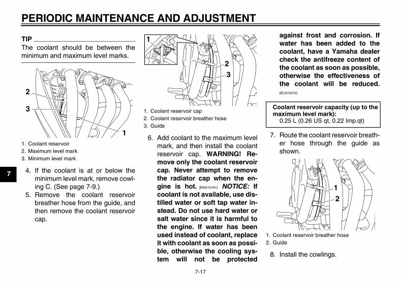
PERIODIC MAINTENANCE AND ADJUSTMENT
7-17
7
TIPThe coolant should be between theminimum and maximum level marks.
4. If the coolant is at or below theminimum level mark, remove cowl-ing C. (See page 7-9.)
5. Remove the coolant reservoirbreather hose from the guide, andthen remove the coolant reservoircap.
6. Add coolant to the maximum levelmark, and then install the coolantreservoir cap. WARNING! Re-move only the coolant reservoircap. Never attempt to removethe radiator cap when the en-gine is hot. [EWA15161] NOTICE: Ifcoolant is not available, use dis-tilled water or soft tap water in-stead. Do not use hard water orsalt water since it is harmful tothe engine. If water has beenused instead of coolant, replaceit with coolant as soon as possi-ble, otherwise the cooling sys-tem will not be protected
against frost and corrosion. Ifwater has been added to thecoolant, have a Yamaha dealercheck the antifreeze content ofthe coolant as soon as possible,otherwise the effectiveness ofthe coolant will be reduced.[ECA10472]
7. Route the coolant reservoir breath-er hose through the guide asshown.
8. Install the cowlings.
1. Coolant reservoir2. Maximum level mark3. Minimum level mark
1
2
3 1. Coolant reservoir cap2. Coolant reservoir breather hose3. Guide
3
1
2
Coolant reservoir capacity (up to the maximum level mark):
0.25 L (0.26 US qt, 0.22 Imp.qt)
1. Coolant reservoir breather hose2. Guide
21
U36P10E0.book Page 17 Thursday, November 13, 2008 4:45 PM
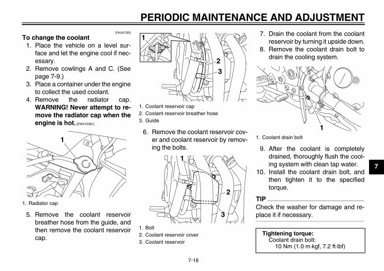
PERIODIC MAINTENANCE AND ADJUSTMENT
7-18
7
EAU47320
To change the coolant1. Place the vehicle on a level sur-
face and let the engine cool if nec-essary.
2. Remove cowlings A and C. (Seepage 7-9.)
3. Place a container under the engineto collect the used coolant.
4. Remove the radiator cap.WARNING! Never attempt to re-move the radiator cap when theengine is hot. [EWA10381]
5. Remove the coolant reservoirbreather hose from the guide, andthen remove the coolant reservoircap.
6. Remove the coolant reservoir cov-er and coolant reservoir by remov-ing the bolts.
7. Drain the coolant from the coolantreservoir by turning it upside down.
8. Remove the coolant drain bolt todrain the cooling system.
9. After the coolant is completelydrained, thoroughly flush the cool-ing system with clean tap water.
10. Install the coolant drain bolt, andthen tighten it to the specifiedtorque.
TIPCheck the washer for damage and re-place it if necessary.
1. Radiator cap
1
1. Coolant reservoir cap2. Coolant reservoir breather hose3. Guide
1. Bolt2. Coolant reservoir cover3. Coolant reservoir
3
1
2
2
3
1
1. Coolant drain bolt
Tightening torque:Coolant drain bolt:
10 Nm (1.0 m·kgf, 7.2 ft·lbf)
1
U36P10E0.book Page 18 Thursday, November 13, 2008 4:45 PM
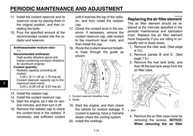
PERIODIC MAINTENANCE AND ADJUSTMENT
7-19
7
11. Install the coolant reservoir and itsreservoir cover by placing them inthe original position, and then in-stalling the bolts.
12. Pour the specified amount of therecommended coolant into the ra-diator and reservoir.
13. Install the radiator cap.14. Install the coolant reservoir cap.15. Start the engine, let it idle for sev-
eral minutes, and then turn it off.16. Remove the radiator cap to check
the coolant level in the radiator. Ifnecessary, add sufficient coolant
until it reaches the top of the radia-tor, and then install the radiatorcap.
17. Check the coolant level in the res-ervoir. If necessary, remove thecoolant reservoir cap, add coolantto the maximum level mark, andthen install the cap.
18. Route the coolant reservoir breath-er hose through the guide asshown.
19. Start the engine, and then checkthe vehicle for coolant leakage. Ifcoolant is leaking, have a Yamahadealer check the cooling system.
20. Install the cowlings.
EAU47460
Replacing the air filter element The air filter element should be re-placed at the intervals specified in theperiodic maintenance and lubricationchart. Replace the air filter elementmore frequently if you are riding in un-usually wet or dusty areas.
1. Remove the rider seat. (See page4-13.)
2. Remove panels B and C. (Seepage 7-9.)
3. Remove the fuel tank bolts, andthen lift the fuel tank away from theair filter case.
4. Remove the air filter case cover byremoving the screws. NOTICE:When removing the air filter
Antifreeze/water mixture ratio:1:1
Recommended antifreeze:High-quality ethylene glycol anti-freeze containing corrosion inhibitors for aluminum engines
Coolant quantity:Radiator capacity (including all routes):
2.00 L (2.11 US qt, 1.76 Imp.qt)Coolant reservoir capacity (up to the maximum level mark):
0.25 L (0.26 US qt, 0.22 Imp.qt)
1. Coolant reservoir breather hose2. Guide
21
1. Bolt
1
U36P10E0.book Page 19 Thursday, November 13, 2008 4:45 PM
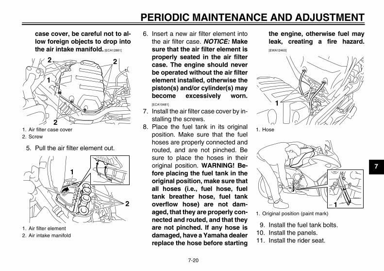
PERIODIC MAINTENANCE AND ADJUSTMENT
7-20
7
case cover, be careful not to al-low foreign objects to drop intothe air intake manifold. [ECA12881]
5. Pull the air filter element out.
6. Insert a new air filter element intothe air filter case. NOTICE: Makesure that the air filter element isproperly seated in the air filtercase. The engine should neverbe operated without the air filterelement installed, otherwise thepiston(s) and/or cylinder(s) maybecome excessively worn.[ECA10481]
7. Install the air filter case cover by in-stalling the screws.
8. Place the fuel tank in its originalposition. Make sure that the fuelhoses are properly connected androuted, and are not pinched. Besure to place the hoses in theiroriginal position. WARNING! Be-fore placing the fuel tank in theoriginal position, make sure thatall hoses (i.e., fuel hose, fueltank breather hose, fuel tankoverflow hose) are not dam-aged, that they are properly con-nected and routed, and that theyare not pinched. If any hose isdamaged, have a Yamaha dealerreplace the hose before starting
the engine, otherwise fuel mayleak, creating a fire hazard.[EWA12463]
9. Install the fuel tank bolts.10. Install the panels.11. Install the rider seat.
1. Air filter case cover2. Screw
1. Air filter element2. Air intake manifold
1
2 2
2
2
1
1. Hose
1. Original position (paint mark)
1
1
U36P10E0.book Page 20 Thursday, November 13, 2008 4:45 PM
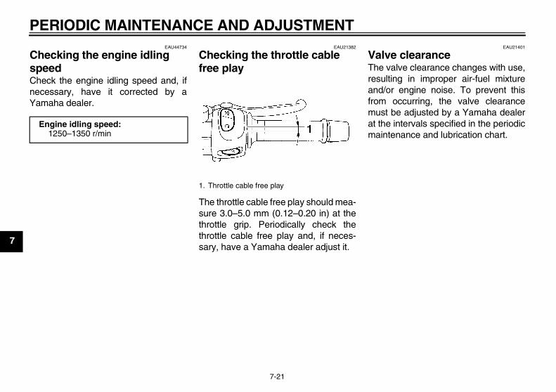
PERIODIC MAINTENANCE AND ADJUSTMENT
7-21
7
EAU44734
Checking the engine idling speed Check the engine idling speed and, ifnecessary, have it corrected by aYamaha dealer.
EAU21382
Checking the throttle cable free play
The throttle cable free play should mea-sure 3.0–5.0 mm (0.12–0.20 in) at thethrottle grip. Periodically check thethrottle cable free play and, if neces-sary, have a Yamaha dealer adjust it.
EAU21401
Valve clearance The valve clearance changes with use,resulting in improper air-fuel mixtureand/or engine noise. To prevent thisfrom occurring, the valve clearancemust be adjusted by a Yamaha dealerat the intervals specified in the periodicmaintenance and lubrication chart.
Engine idling speed:1250–1350 r/min
1. Throttle cable free play
U36P10E0.book Page 21 Thursday, November 13, 2008 4:45 PM
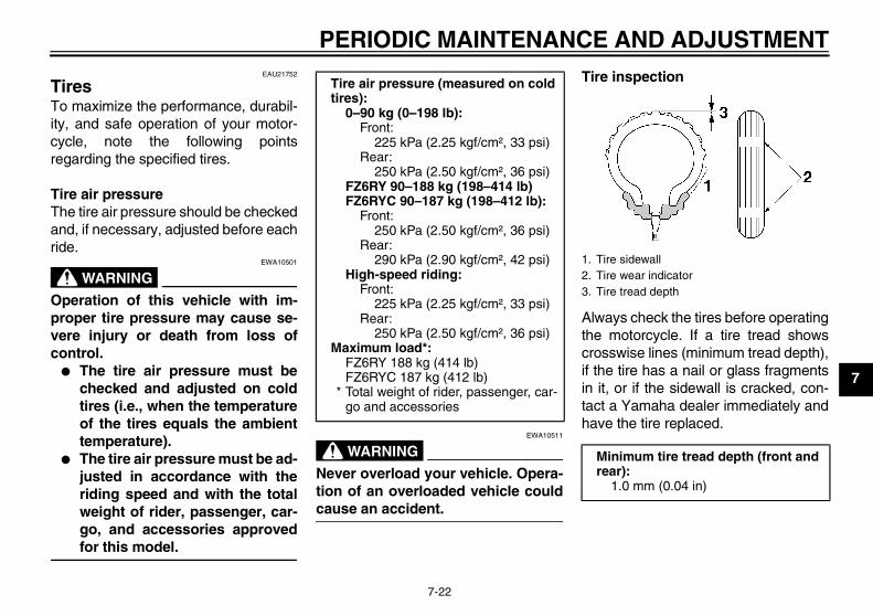
PERIODIC MAINTENANCE AND ADJUSTMENT
7-22
7
EAU21752
Tires To maximize the performance, durabil-ity, and safe operation of your motor-cycle, note the following pointsregarding the specified tires.
Tire air pressureThe tire air pressure should be checkedand, if necessary, adjusted before eachride.
WARNINGEWA10501
Operation of this vehicle with im-proper tire pressure may cause se-vere injury or death from loss ofcontrol.
� The tire air pressure must bechecked and adjusted on coldtires (i.e., when the temperatureof the tires equals the ambienttemperature).
� The tire air pressure must be ad-justed in accordance with theriding speed and with the totalweight of rider, passenger, car-go, and accessories approvedfor this model.
WARNINGEWA10511
Never overload your vehicle. Opera-tion of an overloaded vehicle couldcause an accident.
Tire inspection
Always check the tires before operatingthe motorcycle. If a tire tread showscrosswise lines (minimum tread depth),if the tire has a nail or glass fragmentsin it, or if the sidewall is cracked, con-tact a Yamaha dealer immediately andhave the tire replaced.
Tire air pressure (measured on cold tires):
0–90 kg (0–198 lb):Front:
225 kPa (2.25 kgf/cm², 33 psi)Rear:
250 kPa (2.50 kgf/cm², 36 psi)FZ6RY 90–188 kg (198–414 lb)FZ6RYC 90–187 kg (198–412 lb):
Front:250 kPa (2.50 kgf/cm², 36 psi)
Rear:290 kPa (2.90 kgf/cm², 42 psi)
High-speed riding:Front:
225 kPa (2.25 kgf/cm², 33 psi)Rear:
250 kPa (2.50 kgf/cm², 36 psi)Maximum load*:
FZ6RY 188 kg (414 lb)FZ6RYC 187 kg (412 lb)
* Total weight of rider, passenger, car-go and accessories
1. Tire sidewall2. Tire wear indicator3. Tire tread depth
Minimum tire tread depth (front and rear):
1.0 mm (0.04 in)
U36P10E0.book Page 22 Thursday, November 13, 2008 4:45 PM

PERIODIC MAINTENANCE AND ADJUSTMENT
7-23
7
WARNINGEWA10580
� It is dangerous to ride with aworn-out tire. When a tire treadbegins to show crosswise lines,have a Yamaha dealer replacethe tire immediately.
� The replacement of all wheel-and brake-related parts, includ-ing the tires, should be left to aYamaha dealer, who has thenecessary professional knowl-edge and experience.
Tire information
This motorcycle is equipped with castwheels and tubeless tires with valves.
WARNINGEWA10481
� The front and rear tires shouldbe of the same make and de-sign, otherwise the handlingcharacteristics of the motor-cycle may be different, whichcould lead to an accident.
� Always make sure that the valvecaps are securely installed toprevent air pressure leakage.
� Use only the tire valves andvalve cores listed below toavoid tire deflation during ahigh-speed ride.
After extensive tests, only the tires list-ed below have been approved for thismodel by Yamaha Motor Co., Ltd.
WARNINGEWA10600
This motorcycle is fitted with super-high-speed tires. Note the followingpoints in order to make the most ef-ficient use of these tires.
� Use only the specified replace-ment tires. Other tires may runthe danger of bursting at superhigh speeds.
� Brand-new tires can have a rela-tively poor grip on certain roadsurfaces until they have been
1. Tire air valve2. Tire air valve core3. Tire air valve cap with seal
Front tire:Size:
120/70 ZR17M/C (58W)Manufacturer/model:
BRIDGESTONE/BT021DUNLOP/ROADSMART
Rear tire:Size:
160/60 ZR17M/C (69W)Manufacturer/model:
BRIDGESTONE/BT021DUNLOP/ROADSMART
FRONT and REAR:Tire air valve:
TR412Valve core:
#9100 (original)
U36P10E0.book Page 23 Thursday, November 13, 2008 4:45 PM
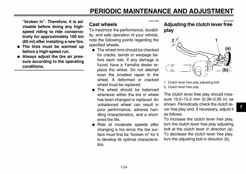
PERIODIC MAINTENANCE AND ADJUSTMENT
7-24
7
“broken in”. Therefore, it is ad-visable before doing any high-speed riding to ride conserva-tively for approximately 100 km(60 mi) after installing a new tire.
� The tires must be warmed upbefore a high-speed run.
� Always adjust the tire air pres-sure according to the operatingconditions.
EAU21960
Cast wheels To maximize the performance, durabil-ity, and safe operation of your vehicle,note the following points regarding thespecified wheels.
� The wheel rims should be checkedfor cracks, bends or warpage be-fore each ride. If any damage isfound, have a Yamaha dealer re-place the wheel. Do not attempteven the smallest repair to thewheel. A deformed or crackedwheel must be replaced.
� The wheel should be balancedwhenever either the tire or wheelhas been changed or replaced. Anunbalanced wheel can result inpoor performance, adverse han-dling characteristics, and a short-ened tire life.
� Ride at moderate speeds afterchanging a tire since the tire sur-face must first be “broken in” for itto develop its optimal characteris-tics.
EAU47390
Adjusting the clutch lever free play
The clutch lever free play should mea-sure 10.0–15.0 mm (0.39–0.59 in) asshown. Periodically check the clutch le-ver free play and, if necessary, adjust itas follows.To increase the clutch lever free play,turn the clutch lever free play adjustingbolt at the clutch lever in direction (a).To decrease the clutch lever free play,turn the adjusting bolt in direction (b).
1. Clutch lever free play adjusting bolt2. Clutch lever free play
2
U36P10E0.book Page 24 Thursday, November 13, 2008 4:45 PM
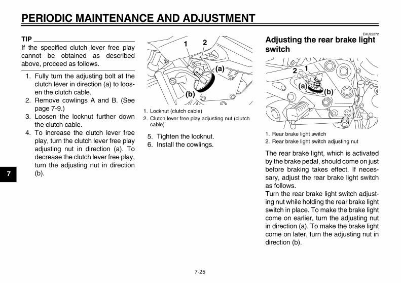
PERIODIC MAINTENANCE AND ADJUSTMENT
7-25
7
TIPIf the specified clutch lever free playcannot be obtained as describedabove, proceed as follows.
1. Fully turn the adjusting bolt at theclutch lever in direction (a) to loos-en the clutch cable.
2. Remove cowlings A and B. (Seepage 7-9.)
3. Loosen the locknut further downthe clutch cable.
4. To increase the clutch lever freeplay, turn the clutch lever free playadjusting nut in direction (a). Todecrease the clutch lever free play,turn the adjusting nut in direction(b).
5. Tighten the locknut.6. Install the cowlings.
EAU22272
Adjusting the rear brake light switch
The rear brake light, which is activatedby the brake pedal, should come on justbefore braking takes effect. If neces-sary, adjust the rear brake light switchas follows.Turn the rear brake light switch adjust-ing nut while holding the rear brake lightswitch in place. To make the brake lightcome on earlier, turn the adjusting nutin direction (a). To make the brake lightcome on later, turn the adjusting nut indirection (b).
1. Locknut (clutch cable)2. Clutch lever free play adjusting nut (clutch
cable)
1 2
(a)
(b)
1. Rear brake light switch2. Rear brake light switch adjusting nut
12
(a)(b)
U36P10E0.book Page 25 Thursday, November 13, 2008 4:45 PM
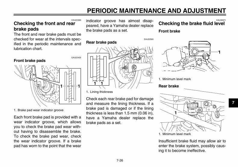
PERIODIC MAINTENANCE AND ADJUSTMENT
7-26
7
EAU22390
Checking the front and rear brake pads The front and rear brake pads must bechecked for wear at the intervals spec-ified in the periodic maintenance andlubrication chart.
EAU22420
Front brake pads
Each front brake pad is provided with awear indicator groove, which allowsyou to check the brake pad wear with-out having to disassemble the brake.To check the brake pad wear, checkthe wear indicator groove. If a brakepad has worn to the point that the wear
indicator groove has almost disap-peared, have a Yamaha dealer replacethe brake pads as a set.
EAU22500
Rear brake pads
Check each rear brake pad for damageand measure the lining thickness. If abrake pad is damaged or if the liningthickness is less than 1.5 mm (0.06 in),have a Yamaha dealer replace thebrake pads as a set.
EAU39371
Checking the brake fluid level
Front brake
Rear brake
Insufficient brake fluid may allow air toenter the brake system, possibly caus-ing it to become ineffective.
1. Brake pad wear indicator groove
111. Lining thickness
111. Minimum level mark
1. Minimum level mark
1
U36P10E0.book Page 26 Thursday, November 13, 2008 4:45 PM
PERIODIC MAINTENANCE AND ADJUSTMENT
7-27
7
Before riding, check that the brake fluidis above the minimum level mark andreplenish if necessary. A low brake fluidlevel may indicate worn brake padsand/or brake system leakage. If thebrake fluid level is low, be sure to checkthe brake pads for wear and the brakesystem for leakage.
TIPThe rear brake fluid reservoir is locatedbehind panel A. (See page 7-9.)
Observe these precautions:� When checking the fluid level,
make sure that the top of the brakefluid reservoir is level.
� Use only the recommended qualitybrake fluid, otherwise the rubberseals may deteriorate, causingleakage and poor braking perfor-mance.
� Refill with the same type of brakefluid. Mixing fluids may result in aharmful chemical reaction andlead to poor braking performance.
� Be careful that water does not en-ter the brake fluid reservoir whenrefilling. Water will significantlylower the boiling point of the fluidand may result in vapor lock.
� Brake fluid may deteriorate paint-ed surfaces or plastic parts. Al-ways clean up spilled fluidimmediately.
� As the brake pads wear, it is nor-mal for the brake fluid level to grad-ually go down. However, if thebrake fluid level goes down sud-denly, have a Yamaha dealercheck the cause.
EAU22731
Changing the brake fluid Have a Yamaha dealer change thebrake fluid at the intervals specified inthe TIP after the periodic maintenanceand lubrication chart. In addition, havethe oil seals of the master cylinders andcalipers as well as the brake hoses re-placed at the intervals listed below orwhenever they are damaged or leak-ing.
� Oil seals: Replace every twoyears.
� Brake hoses: Replace every fouryears.
Recommended brake fluid:DOT 4
U36P10E0.book Page 27 Thursday, November 13, 2008 4:45 PM
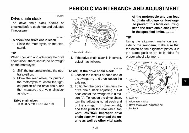
PERIODIC MAINTENANCE AND ADJUSTMENT
7-28
7
EAU22760
Drive chain slack The drive chain slack should bechecked before each ride and adjustedif necessary.
EAU22773
To check the drive chain slack1. Place the motorcycle on the side-
stand.
TIPWhen checking and adjusting the drivechain slack, there should be no weighton the motorcycle.
2. Shift the transmission into the neu-tral position.
3. Move the rear wheel by pushingthe motorcycle to locate the tight-est portion of the drive chain, andthen measure the drive chain slackas shown.
4. If the drive chain slack is incorrect,adjust it as follows.
EAU47031
To adjust the drive chain slack1. Loosen the locknut at each end of
the swingarm, and then loosen theaxle nut.
2. To tighten the drive chain, turn thedrive chain slack adjusting nut ateach end of the swingarm in direc-tion (a). To loosen the drive chain,turn the adjusting nut at each endof the swingarm in direction (b),and then push the rear wheel for-ward. NOTICE: Improper drivechain slack will overload the en-gine as well as other vital parts
of the motorcycle and can leadto chain slippage or breakage.To prevent this from occurring,keep the drive chain slack with-in the specified limits. [ECA10571]
TIPUsing the alignment marks on eachside of the swingarm, make sure thatthe notch on the alignment plates is inthe same position on both sides forproper wheel alignment.
Drive chain slack:45.0–55.0 mm (1.77–2.17 in)
1. Drive chain slack
1
1. Axle nut2. Alignment marks3. Drive chain slack adjusting nut4. Locknut
1 3
4
2
(a)
(b)
U36P10E0.book Page 28 Thursday, November 13, 2008 4:45 PM
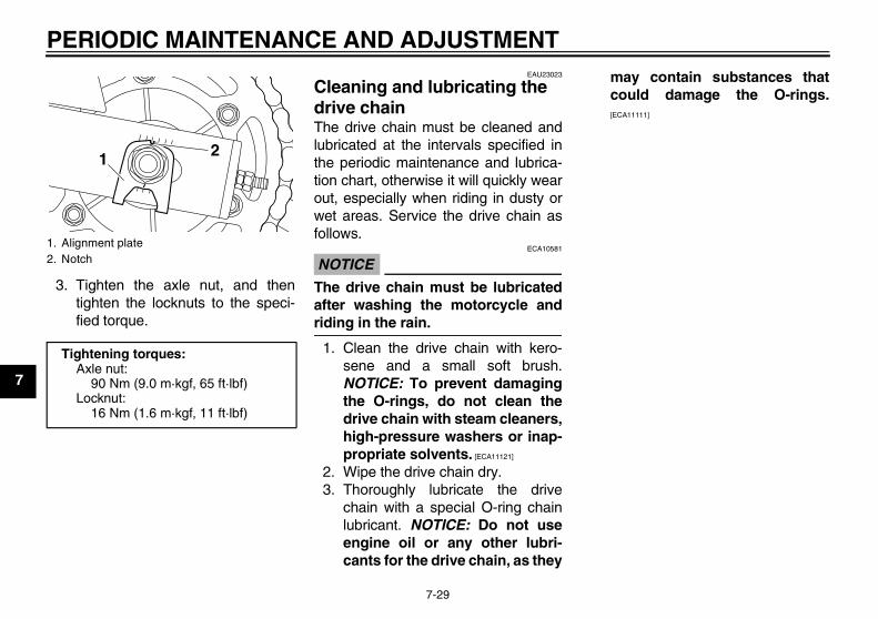
PERIODIC MAINTENANCE AND ADJUSTMENT
7-29
7
3. Tighten the axle nut, and thentighten the locknuts to the speci-fied torque.
EAU23023
Cleaning and lubricating the drive chain The drive chain must be cleaned andlubricated at the intervals specified inthe periodic maintenance and lubrica-tion chart, otherwise it will quickly wearout, especially when riding in dusty orwet areas. Service the drive chain asfollows.
NOTICEECA10581
The drive chain must be lubricatedafter washing the motorcycle andriding in the rain.
1. Clean the drive chain with kero-sene and a small soft brush.NOTICE: To prevent damagingthe O-rings, do not clean thedrive chain with steam cleaners,high-pressure washers or inap-propriate solvents. [ECA11121]
2. Wipe the drive chain dry.3. Thoroughly lubricate the drive
chain with a special O-ring chainlubricant. NOTICE: Do not useengine oil or any other lubri-cants for the drive chain, as they
may contain substances thatcould damage the O-rings.[ECA11111]
1. Alignment plate2. Notch
Tightening torques:Axle nut:
90 Nm (9.0 m·kgf, 65 ft·lbf)Locknut:
16 Nm (1.6 m·kgf, 11 ft·lbf)
1 2
U36P10E0.book Page 29 Thursday, November 13, 2008 4:45 PM
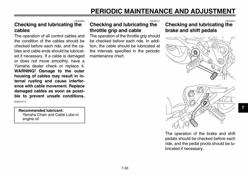
PERIODIC MAINTENANCE AND ADJUSTMENT
7-30
7
EAU23093
Checking and lubricating the cables The operation of all control cables andthe condition of the cables should bechecked before each ride, and the ca-bles and cable ends should be lubricat-ed if necessary. If a cable is damagedor does not move smoothly, have aYamaha dealer check or replace it.WARNING! Damage to the outerhousing of cables may result in in-ternal rusting and cause interfer-ence with cable movement. Replacedamaged cables as soon as possi-ble to prevent unsafe conditions.[EWA10711]
EAU23111
Checking and lubricating the throttle grip and cable The operation of the throttle grip shouldbe checked before each ride. In addi-tion, the cable should be lubricated atthe intervals specified in the periodicmaintenance chart.
EAU44271
Checking and lubricating the brake and shift pedals
The operation of the brake and shiftpedals should be checked before eachride, and the pedal pivots should be lu-bricated if necessary.
Recommended lubricant:Yamaha Chain and Cable Lube or engine oil
U36P10E0.book Page 30 Thursday, November 13, 2008 4:45 PM
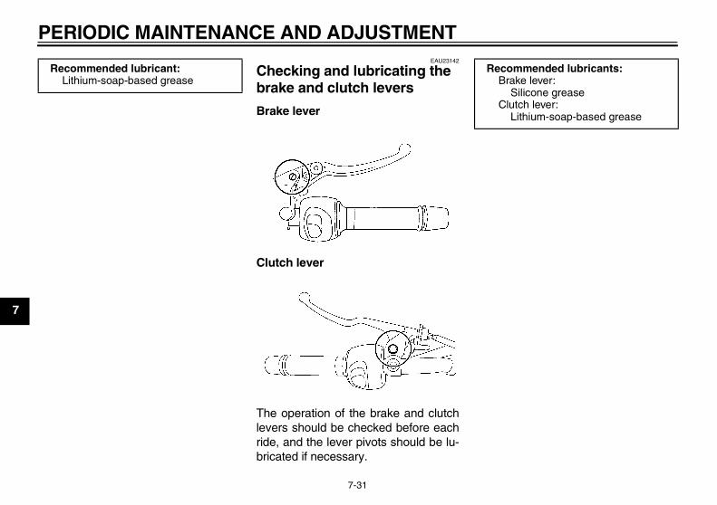
PERIODIC MAINTENANCE AND ADJUSTMENT
7-31
7
EAU23142
Checking and lubricating the brake and clutch levers
Brake lever
Clutch lever
The operation of the brake and clutchlevers should be checked before eachride, and the lever pivots should be lu-bricated if necessary.
Recommended lubricant:Lithium-soap-based grease
Recommended lubricants:Brake lever:
Silicone greaseClutch lever:
Lithium-soap-based grease
U36P10E0.book Page 31 Thursday, November 13, 2008 4:45 PM
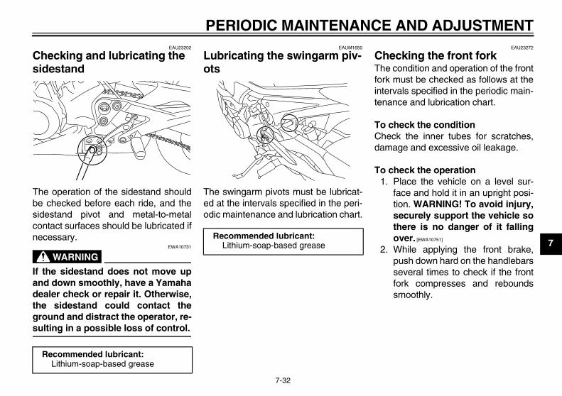
PERIODIC MAINTENANCE AND ADJUSTMENT
7-32
7
EAU23202
Checking and lubricating the sidestand
The operation of the sidestand shouldbe checked before each ride, and thesidestand pivot and metal-to-metalcontact surfaces should be lubricated ifnecessary.
WARNINGEWA10731
If the sidestand does not move upand down smoothly, have a Yamahadealer check or repair it. Otherwise,the sidestand could contact theground and distract the operator, re-sulting in a possible loss of control.
EAUM1650
Lubricating the swingarm piv-ots
The swingarm pivots must be lubricat-ed at the intervals specified in the peri-odic maintenance and lubrication chart.
EAU23272
Checking the front fork The condition and operation of the frontfork must be checked as follows at theintervals specified in the periodic main-tenance and lubrication chart.
To check the conditionCheck the inner tubes for scratches,damage and excessive oil leakage.
To check the operation1. Place the vehicle on a level sur-
face and hold it in an upright posi-tion. WARNING! To avoid injury,securely support the vehicle sothere is no danger of it fallingover. [EWA10751]
2. While applying the front brake,push down hard on the handlebarsseveral times to check if the frontfork compresses and reboundssmoothly.
Recommended lubricant:Lithium-soap-based grease
Recommended lubricant:Lithium-soap-based grease
U36P10E0.book Page 32 Thursday, November 13, 2008 4:45 PM
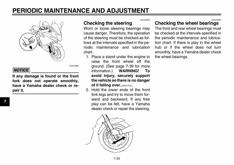
PERIODIC MAINTENANCE AND ADJUSTMENT
7-33
7
NOTICEECA10590
If any damage is found or the frontfork does not operate smoothly,have a Yamaha dealer check or re-pair it.
EAU23283
Checking the steering Worn or loose steering bearings maycause danger. Therefore, the operationof the steering must be checked as fol-lows at the intervals specified in the pe-riodic maintenance and lubricationchart.
1. Place a stand under the engine toraise the front wheel off theground. (See page 7-39 for moreinformation.) WARNING! Toavoid injury, securely supportthe vehicle so there is no dangerof it falling over. [EWA10751]
2. Hold the lower ends of the frontfork legs and try to move them for-ward and backward. If any freeplay can be felt, have a Yamahadealer check or repair the steering.
EAU23290
Checking the wheel bearings The front and rear wheel bearings mustbe checked at the intervals specified inthe periodic maintenance and lubrica-tion chart. If there is play in the wheelhub or if the wheel does not turnsmoothly, have a Yamaha dealer checkthe wheel bearings.
U36P10E0.book Page 33 Thursday, November 13, 2008 4:45 PM
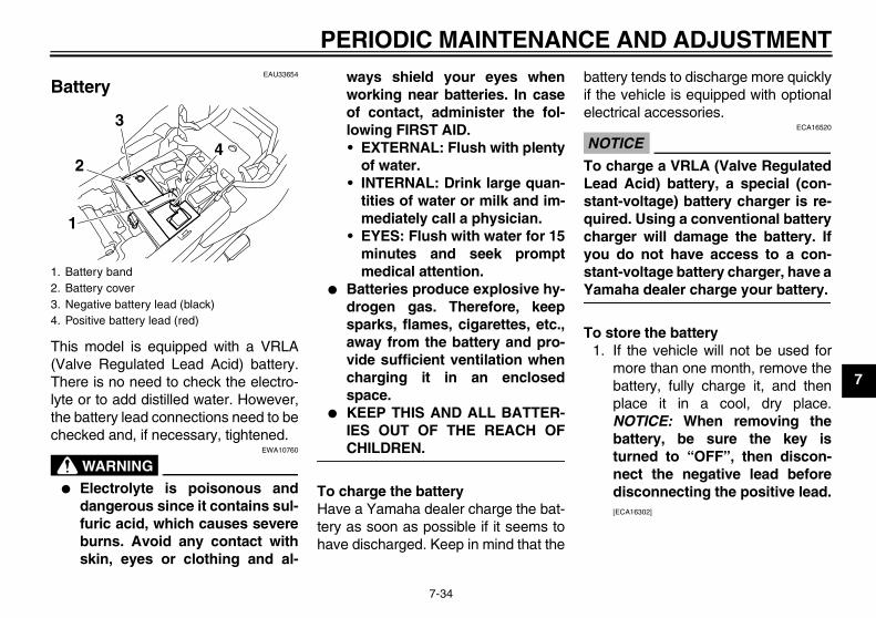
PERIODIC MAINTENANCE AND ADJUSTMENT
7-34
7
EAU33654
Battery
This model is equipped with a VRLA(Valve Regulated Lead Acid) battery.There is no need to check the electro-lyte or to add distilled water. However,the battery lead connections need to bechecked and, if necessary, tightened.
WARNINGEWA10760
� Electrolyte is poisonous anddangerous since it contains sul-furic acid, which causes severeburns. Avoid any contact withskin, eyes or clothing and al-
ways shield your eyes whenworking near batteries. In caseof contact, administer the fol-lowing FIRST AID.• EXTERNAL: Flush with plenty
of water.• INTERNAL: Drink large quan-
tities of water or milk and im-mediately call a physician.
• EYES: Flush with water for 15minutes and seek promptmedical attention.
� Batteries produce explosive hy-drogen gas. Therefore, keepsparks, flames, cigarettes, etc.,away from the battery and pro-vide sufficient ventilation whencharging it in an enclosedspace.
� KEEP THIS AND ALL BATTER-IES OUT OF THE REACH OFCHILDREN.
To charge the batteryHave a Yamaha dealer charge the bat-tery as soon as possible if it seems tohave discharged. Keep in mind that the
battery tends to discharge more quicklyif the vehicle is equipped with optionalelectrical accessories.
NOTICEECA16520
To charge a VRLA (Valve RegulatedLead Acid) battery, a special (con-stant-voltage) battery charger is re-quired. Using a conventional batterycharger will damage the battery. Ifyou do not have access to a con-stant-voltage battery charger, have aYamaha dealer charge your battery.
To store the battery1. If the vehicle will not be used for
more than one month, remove thebattery, fully charge it, and thenplace it in a cool, dry place.NOTICE: When removing thebattery, be sure the key isturned to “OFF”, then discon-nect the negative lead beforedisconnecting the positive lead.[ECA16302]
1. Battery band2. Battery cover3. Negative battery lead (black)4. Positive battery lead (red)
2
1
3
4
U36P10E0.book Page 34 Thursday, November 13, 2008 4:45 PM
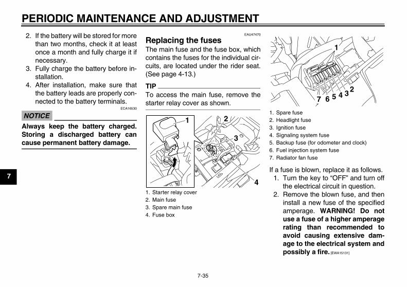
PERIODIC MAINTENANCE AND ADJUSTMENT
7-35
7
2. If the battery will be stored for morethan two months, check it at leastonce a month and fully charge it ifnecessary.
3. Fully charge the battery before in-stallation.
4. After installation, make sure thatthe battery leads are properly con-nected to the battery terminals.
NOTICEECA16530
Always keep the battery charged.Storing a discharged battery cancause permanent battery damage.
EAU47470
Replacing the fuses The main fuse and the fuse box, whichcontains the fuses for the individual cir-cuits, are located under the rider seat.(See page 4-13.)
TIPTo access the main fuse, remove thestarter relay cover as shown.
If a fuse is blown, replace it as follows.1. Turn the key to “OFF” and turn off
the electrical circuit in question.2. Remove the blown fuse, and then
install a new fuse of the specifiedamperage. WARNING! Do notuse a fuse of a higher amperagerating than recommended toavoid causing extensive dam-age to the electrical system andpossibly a fire. [EWA15131]
1. Starter relay cover2. Main fuse3. Spare main fuse4. Fuse box
2
4
3
11. Spare fuse2. Headlight fuse3. Ignition fuse4. Signaling system fuse5. Backup fuse (for odometer and clock)6. Fuel injection system fuse7. Radiator fan fuse
1
234567
U36P10E0.book Page 35 Thursday, November 13, 2008 4:45 PM
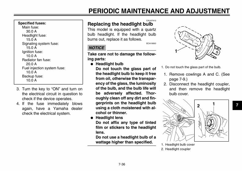
PERIODIC MAINTENANCE AND ADJUSTMENT
7-36
7
3. Turn the key to “ON” and turn onthe electrical circuit in question tocheck if the device operates.
4. If the fuse immediately blowsagain, have a Yamaha dealercheck the electrical system.
EAU47410
Replacing the headlight bulb This model is equipped with a quartzbulb headlight. If the headlight bulbburns out, replace it as follows.
NOTICEECA10650
Take care not to damage the follow-ing parts:
� Headlight bulbDo not touch the glass part ofthe headlight bulb to keep it freefrom oil, otherwise the transpar-ency of the glass, the luminosityof the bulb, and the bulb life willbe adversely affected. Thor-oughly clean off any dirt and fin-gerprints on the headlight bulbusing a cloth moistened with al-cohol or thinner.
� Headlight lensDo not affix any type of tintedfilm or stickers to the headlightlens.Do not use a headlight bulb of awattage higher than specified.
1. Remove cowlings A and C. (Seepage 7-9.)
2. Disconnect the headlight coupler,and then remove the headlightbulb cover.
Specified fuses:Main fuse:
30.0 AHeadlight fuse:
15.0 ASignaling system fuse:
15.0 AIgnition fuse:
10.0 ARadiator fan fuse:
20.0 AFuel injection system fuse:
10.0 ABackup fuse:
10.0 A
1. Do not touch the glass part of the bulb.
1. Headlight bulb cover2. Headlight coupler
12
U36P10E0.book Page 36 Thursday, November 13, 2008 4:45 PM
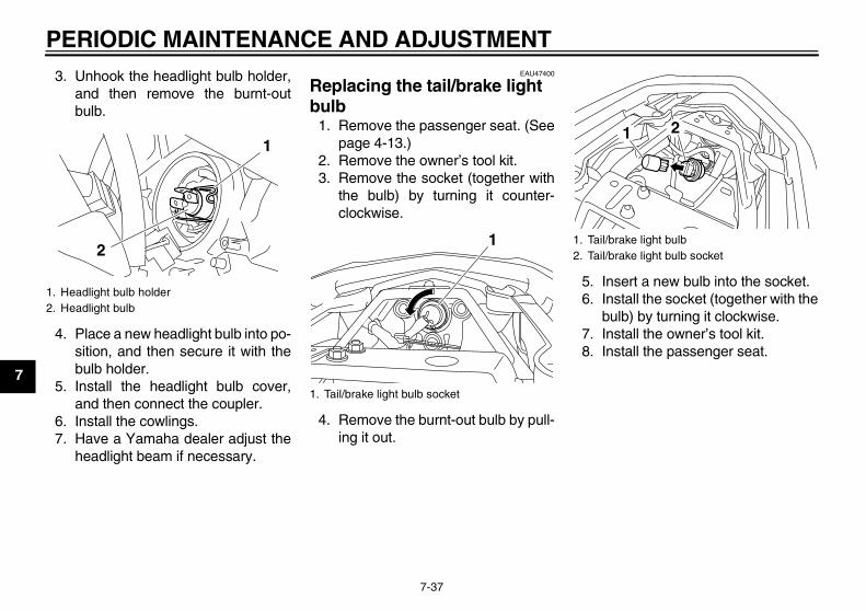
PERIODIC MAINTENANCE AND ADJUSTMENT
7-37
7
3. Unhook the headlight bulb holder,and then remove the burnt-outbulb.
4. Place a new headlight bulb into po-sition, and then secure it with thebulb holder.
5. Install the headlight bulb cover,and then connect the coupler.
6. Install the cowlings.7. Have a Yamaha dealer adjust the
headlight beam if necessary.
EAU47400
Replacing the tail/brake light bulb
1. Remove the passenger seat. (Seepage 4-13.)
2. Remove the owner’s tool kit.3. Remove the socket (together with
the bulb) by turning it counter-clockwise.
4. Remove the burnt-out bulb by pull-ing it out.
5. Insert a new bulb into the socket.6. Install the socket (together with the
bulb) by turning it clockwise.7. Install the owner’s tool kit.8. Install the passenger seat.
1. Headlight bulb holder2. Headlight bulb
1
2
1. Tail/brake light bulb socket
1 1. Tail/brake light bulb2. Tail/brake light bulb socket
21
U36P10E0.book Page 37 Thursday, November 13, 2008 4:45 PM
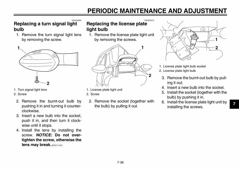
PERIODIC MAINTENANCE AND ADJUSTMENT
7-38
7
EAU24204
Replacing a turn signal light bulb
1. Remove the turn signal light lensby removing the screw.
2. Remove the burnt-out bulb bypushing it in and turning it counter-clockwise.
3. Insert a new bulb into the socket,push it in, and then turn it clock-wise until it stops.
4. Install the lens by installing thescrew. NOTICE: Do not over-tighten the screw, otherwise thelens may break. [ECA11191]
EAU24312
Replacing the license plate light bulb
1. Remove the license plate light unitby removing the screws.
2. Remove the socket (together withthe bulb) by pulling it out.
3. Remove the burnt-out bulb by pull-ing it out.
4. Insert a new bulb into the socket.5. Install the socket (together with the
bulb) by pushing it in.6. Install the license plate light unit by
installing the screws.
1. Turn signal light lens2. Screw
2
1
1. License plate light unit2. Screw
2
1
1. License plate light bulb socket2. License plate light bulb
1
2
U36P10E0.book Page 38 Thursday, November 13, 2008 4:45 PM
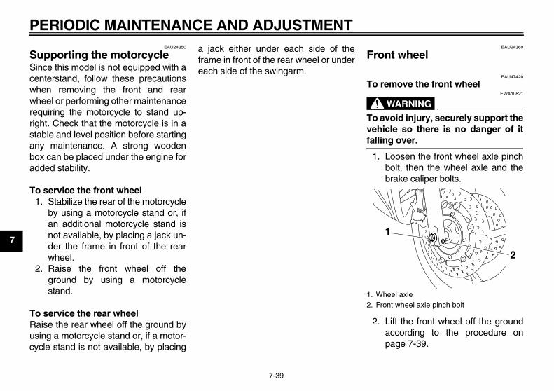
PERIODIC MAINTENANCE AND ADJUSTMENT
7-39
7
EAU24350
Supporting the motorcycle Since this model is not equipped with acenterstand, follow these precautionswhen removing the front and rearwheel or performing other maintenancerequiring the motorcycle to stand up-right. Check that the motorcycle is in astable and level position before startingany maintenance. A strong woodenbox can be placed under the engine foradded stability.
To service the front wheel1. Stabilize the rear of the motorcycle
by using a motorcycle stand or, ifan additional motorcycle stand isnot available, by placing a jack un-der the frame in front of the rearwheel.
2. Raise the front wheel off theground by using a motorcyclestand.
To service the rear wheelRaise the rear wheel off the ground byusing a motorcycle stand or, if a motor-cycle stand is not available, by placing
a jack either under each side of theframe in front of the rear wheel or undereach side of the swingarm.
EAU24360
Front wheel
EAU47420
To remove the front wheel
WARNINGEWA10821
To avoid injury, securely support thevehicle so there is no danger of itfalling over.
1. Loosen the front wheel axle pinchbolt, then the wheel axle and thebrake caliper bolts.
2. Lift the front wheel off the groundaccording to the procedure onpage 7-39.
1. Wheel axle2. Front wheel axle pinch bolt
1
2
U36P10E0.book Page 39 Thursday, November 13, 2008 4:45 PM
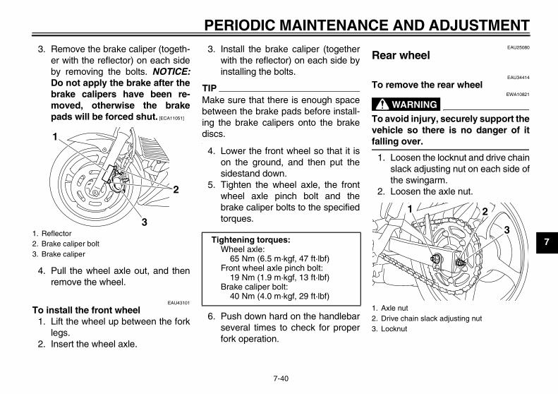
PERIODIC MAINTENANCE AND ADJUSTMENT
7-40
7
3. Remove the brake caliper (togeth-er with the reflector) on each sideby removing the bolts. NOTICE:Do not apply the brake after thebrake calipers have been re-moved, otherwise the brakepads will be forced shut. [ECA11051]
4. Pull the wheel axle out, and thenremove the wheel.
EAU43101
To install the front wheel1. Lift the wheel up between the fork
legs.2. Insert the wheel axle.
3. Install the brake caliper (togetherwith the reflector) on each side byinstalling the bolts.
TIPMake sure that there is enough spacebetween the brake pads before install-ing the brake calipers onto the brakediscs.
4. Lower the front wheel so that it ison the ground, and then put thesidestand down.
5. Tighten the wheel axle, the frontwheel axle pinch bolt and thebrake caliper bolts to the specifiedtorques.
6. Push down hard on the handlebarseveral times to check for properfork operation.
EAU25080
Rear wheel
EAU34414
To remove the rear wheel
WARNINGEWA10821
To avoid injury, securely support thevehicle so there is no danger of itfalling over.
1. Loosen the locknut and drive chainslack adjusting nut on each side ofthe swingarm.
2. Loosen the axle nut.
1. Reflector2. Brake caliper bolt3. Brake caliper
1
2
3
Tightening torques:Wheel axle:
65 Nm (6.5 m·kgf, 47 ft·lbf)Front wheel axle pinch bolt:
19 Nm (1.9 m·kgf, 13 ft·lbf)Brake caliper bolt:
40 Nm (4.0 m·kgf, 29 ft·lbf)1. Axle nut2. Drive chain slack adjusting nut3. Locknut
1
3
2
U36P10E0.book Page 40 Thursday, November 13, 2008 4:45 PM
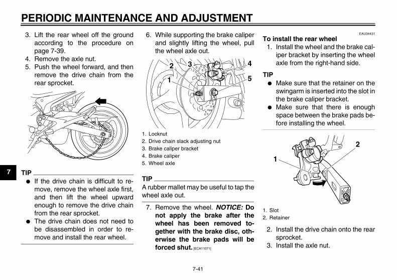
PERIODIC MAINTENANCE AND ADJUSTMENT
7-41
7
3. Lift the rear wheel off the groundaccording to the procedure onpage 7-39.
4. Remove the axle nut.5. Push the wheel forward, and then
remove the drive chain from therear sprocket.
TIP� If the drive chain is difficult to re-
move, remove the wheel axle first,and then lift the wheel upwardenough to remove the drive chainfrom the rear sprocket.
� The drive chain does not need tobe disassembled in order to re-move and install the rear wheel.
6. While supporting the brake caliperand slightly lifting the wheel, pullthe wheel axle out.
TIPA rubber mallet may be useful to tap thewheel axle out.
7. Remove the wheel. NOTICE: Donot apply the brake after thewheel has been removed to-gether with the brake disc, oth-erwise the brake pads will beforced shut. [ECA11071]
EAU34431
To install the rear wheel1. Install the wheel and the brake cal-
iper bracket by inserting the wheelaxle from the right-hand side.
TIP� Make sure that the retainer on the
swingarm is inserted into the slot inthe brake caliper bracket.
� Make sure that there is enoughspace between the brake pads be-fore installing the wheel.
2. Install the drive chain onto the rearsprocket.
3. Install the axle nut.
1. Locknut2. Drive chain slack adjusting nut3. Brake caliper bracket4. Brake caliper5. Wheel axle
1
432
5
1. Slot2. Retainer
1
2
U36P10E0.book Page 41 Thursday, November 13, 2008 4:45 PM
PERIODIC MAINTENANCE AND ADJUSTMENT
7-42
7
4. Lower the rear wheel so that it ison the ground, and then put thesidestand down.
5. Adjust the drive chain slack. (Seepage 7-28.)
6. Tighten the axle nut to the speci-fied torque.
EAU25871
Troubleshooting Although Yamaha motorcycles receivea thorough inspection before shipmentfrom the factory, trouble may occur dur-ing operation. Any problem in the fuel,compression, or ignition systems, forexample, can cause poor starting andloss of power.The following troubleshooting chartsrepresent quick and easy proceduresfor checking these vital systems your-self. However, should your motorcyclerequire any repair, take it to a Yamahadealer, whose skilled technicians havethe necessary tools, experience, andknow-how to service the motorcycleproperly.Use only genuine Yamaha replace-ment parts. Imitation parts may look likeYamaha parts, but they are often inferi-or, have a shorter service life and canlead to expensive repair bills.
WARNINGEWA15141
When checking the fuel system, donot smoke, and make sure there areno open flames or sparks in the ar-ea, including pilot lights from water
heaters or furnaces. Gasoline orgasoline vapors can ignite or ex-plode, causing severe injury orproperty damage.
Tightening torque:Axle nut:
90 Nm (9.0 m·kgf, 65 ft·lbf)
U36P10E0.book Page 42 Thursday, November 13, 2008 4:45 PM
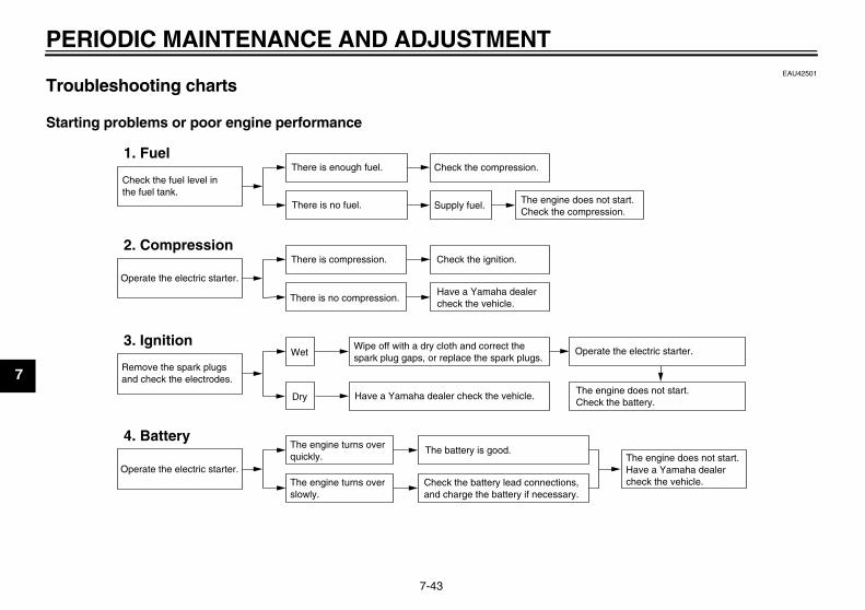
PERIODIC MAINTENANCE AND ADJUSTMENT
7-43
7
EAU42501
Troubleshooting charts
Starting problems or poor engine performance
Check the fuel level inthe fuel tank.
1. FuelThere is enough fuel.
There is no fuel.
Check the compression.
Supply fuel. The engine does not start. Check the compression.
Operate the electric starter.
2. CompressionThere is compression.
There is no compression.
Check the ignition.
Have a Yamaha dealercheck the vehicle.
Remove the spark plugsand check the electrodes.
3. Ignition Wipe off with a dry cloth and correct thespark plug gaps, or replace the spark plugs.
Have a Yamaha dealer check the vehicle.
The engine does not start.Have a Yamaha dealercheck the vehicle.
The engine does not start.Check the battery.
Operate the electric starter.
4. BatteryThe engine turns over quickly.
The engine turns over slowly.
The battery is good.
Check the battery lead connections,and charge the battery if necessary.
Dry
Wet Operate the electric starter.
U36P10E0.book Page 43 Thursday, November 13, 2008 4:45 PM

PERIODIC MAINTENANCE AND ADJUSTMENT
7-44
7
Engine overheating
WARNINGEWAT1040
� Do not remove the radiator cap when the engine and radiator are hot. Scalding hot fluid and steam may beblown out under pressure, which could cause serious injury. Be sure to wait until the engine has cooled.
� Place a thick rag, like a towel, over the radiator cap, and then slowly rotate the cap counterclockwise to the de-tent to allow any residual pressure to escape. When the hissing sound has stopped, press down on the capwhile turning it counterclockwise, and then remove the cap.
TIPIf coolant is not available, tap water can be temporarily used instead, provided that it is changed to the recommended coolantas soon as possible.
Wait until the engine has cooled.
Check the coolant level in the reservoir and radiator.
The coolant level is OK.
The coolant level is low.Check the cooling systemfor leakage.
Have a Yamaha dealer checkand repair the cooling system.
Add coolant. (See TIP.)
Start the engine. If the engine overheats again, have a Yamaha dealer check and repair the cooling system.
There isleakage.
There is no leakage.
U36P10E0.book Page 44 Thursday, November 13, 2008 4:45 PM
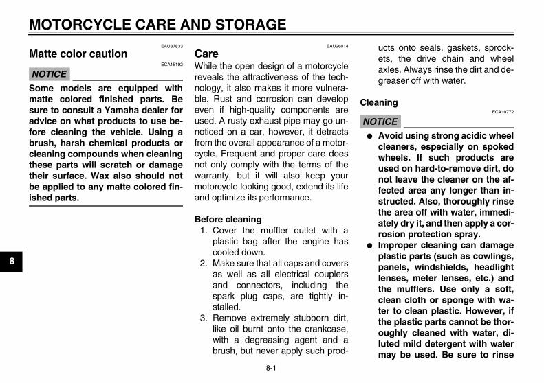
MOTORCYCLE CARE AND STORAGE
8-1
8
EAU37833
Matte color caution
NOTICEECA15192
Some models are equipped withmatte colored finished parts. Besure to consult a Yamaha dealer foradvice on what products to use be-fore cleaning the vehicle. Using abrush, harsh chemical products orcleaning compounds when cleaningthese parts will scratch or damagetheir surface. Wax also should notbe applied to any matte colored fin-ished parts.
EAU26014
Care While the open design of a motorcyclereveals the attractiveness of the tech-nology, it also makes it more vulnera-ble. Rust and corrosion can developeven if high-quality components areused. A rusty exhaust pipe may go un-noticed on a car, however, it detractsfrom the overall appearance of a motor-cycle. Frequent and proper care doesnot only comply with the terms of thewarranty, but it will also keep yourmotorcycle looking good, extend its lifeand optimize its performance.
Before cleaning1. Cover the muffler outlet with a
plastic bag after the engine hascooled down.
2. Make sure that all caps and coversas well as all electrical couplersand connectors, including thespark plug caps, are tightly in-stalled.
3. Remove extremely stubborn dirt,like oil burnt onto the crankcase,with a degreasing agent and abrush, but never apply such prod-
ucts onto seals, gaskets, sprock-ets, the drive chain and wheelaxles. Always rinse the dirt and de-greaser off with water.
Cleaning
NOTICEECA10772
� Avoid using strong acidic wheelcleaners, especially on spokedwheels. If such products areused on hard-to-remove dirt, donot leave the cleaner on the af-fected area any longer than in-structed. Also, thoroughly rinsethe area off with water, immedi-ately dry it, and then apply a cor-rosion protection spray.
� Improper cleaning can damageplastic parts (such as cowlings,panels, windshields, headlightlenses, meter lenses, etc.) andthe mufflers. Use only a soft,clean cloth or sponge with wa-ter to clean plastic. However, ifthe plastic parts cannot be thor-oughly cleaned with water, di-luted mild detergent with watermay be used. Be sure to rinse
U36P10E0.book Page 1 Thursday, November 13, 2008 4:45 PM
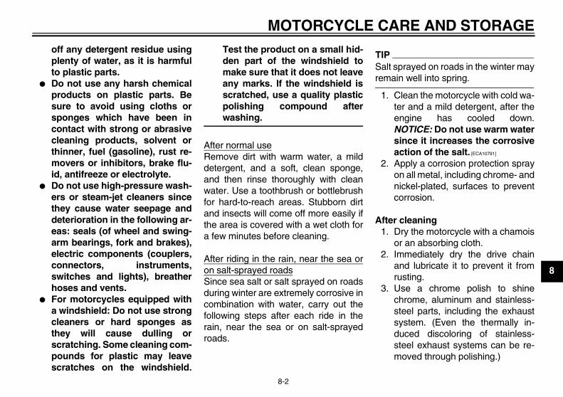
MOTORCYCLE CARE AND STORAGE
8-2
8
off any detergent residue usingplenty of water, as it is harmfulto plastic parts.
� Do not use any harsh chemicalproducts on plastic parts. Besure to avoid using cloths orsponges which have been incontact with strong or abrasivecleaning products, solvent orthinner, fuel (gasoline), rust re-movers or inhibitors, brake flu-id, antifreeze or electrolyte.
� Do not use high-pressure wash-ers or steam-jet cleaners sincethey cause water seepage anddeterioration in the following ar-eas: seals (of wheel and swing-arm bearings, fork and brakes),electric components (couplers,connectors, instruments,switches and lights), breatherhoses and vents.
� For motorcycles equipped witha windshield: Do not use strongcleaners or hard sponges asthey will cause dulling orscratching. Some cleaning com-pounds for plastic may leavescratches on the windshield.
Test the product on a small hid-den part of the windshield tomake sure that it does not leaveany marks. If the windshield isscratched, use a quality plasticpolishing compound afterwashing.
After normal useRemove dirt with warm water, a milddetergent, and a soft, clean sponge,and then rinse thoroughly with cleanwater. Use a toothbrush or bottlebrushfor hard-to-reach areas. Stubborn dirtand insects will come off more easily ifthe area is covered with a wet cloth fora few minutes before cleaning.
After riding in the rain, near the sea oron salt-sprayed roadsSince sea salt or salt sprayed on roadsduring winter are extremely corrosive incombination with water, carry out thefollowing steps after each ride in therain, near the sea or on salt-sprayedroads.
TIPSalt sprayed on roads in the winter mayremain well into spring.
1. Clean the motorcycle with cold wa-ter and a mild detergent, after theengine has cooled down.NOTICE: Do not use warm watersince it increases the corrosiveaction of the salt. [ECA10791]
2. Apply a corrosion protection sprayon all metal, including chrome- andnickel-plated, surfaces to preventcorrosion.
After cleaning1. Dry the motorcycle with a chamois
or an absorbing cloth.2. Immediately dry the drive chain
and lubricate it to prevent it fromrusting.
3. Use a chrome polish to shinechrome, aluminum and stainless-steel parts, including the exhaustsystem. (Even the thermally in-duced discoloring of stainless-steel exhaust systems can be re-moved through polishing.)
U36P10E0.book Page 2 Thursday, November 13, 2008 4:45 PM

MOTORCYCLE CARE AND STORAGE
8-3
8
4. To prevent corrosion, it is recom-mended to apply a corrosion pro-tection spray on all metal,including chrome- and nickel-plat-ed, surfaces.
5. Use spray oil as a universal clean-er to remove any remaining dirt.
6. Touch up minor paint damagecaused by stones, etc.
7. Wax all painted surfaces.8. Let the motorcycle dry completely
before storing or covering it.
WARNINGEWA11131
Contaminants on the brakes or tirescan cause loss of control.
� Make sure that there is no oil orwax on the brakes or tires.
� If necessary, clean the brakediscs and brake linings with aregular brake disc cleaner or ac-etone, and wash the tires withwarm water and a mild deter-gent. Before riding at higherspeeds, test the motorcycle’sbraking performance and cor-nering behavior.
NOTICEECA10800
� Apply spray oil and wax spar-ingly and make sure to wipe offany excess.
� Never apply oil or wax to anyrubber and plastic parts, buttreat them with a suitable careproduct.
� Avoid using abrasive polishingcompounds as they will wearaway the paint.
TIP� Consult a Yamaha dealer for ad-
vice on what products to use.� Washing, rainy weather or humid
climates can cause the headlightlens to fog. Turning the headlighton for a short period of time willhelp remove the moisture from thelens.
EAU26181
Storage
Short-termAlways store your motorcycle in a cool,dry place and, if necessary, protect itagainst dust with a porous cover.
NOTICEECA10810
� Storing the motorcycle in apoorly ventilated room or cover-ing it with a tarp, while it is stillwet, will allow water and humid-ity to seep in and cause rust.
� To prevent corrosion, avoiddamp cellars, stables (becauseof the presence of ammonia)and areas where strong chemi-cals are stored.
Long-termBefore storing your motorcycle for sev-eral months:
1. Follow all the instructions in the“Care” section of this chapter.
2. Fill up the fuel tank and add fuelstabilizer (if available) to preventthe fuel tank from rusting and thefuel from deteriorating.
U36P10E0.book Page 3 Thursday, November 13, 2008 4:45 PM
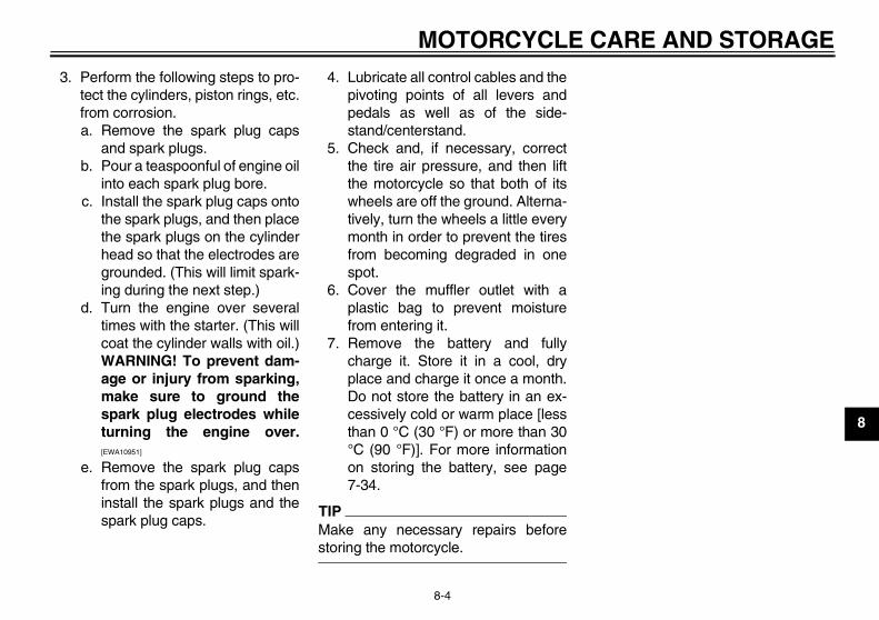
MOTORCYCLE CARE AND STORAGE
8-4
8
3. Perform the following steps to pro-tect the cylinders, piston rings, etc.from corrosion.a. Remove the spark plug caps
and spark plugs.b. Pour a teaspoonful of engine oil
into each spark plug bore.c. Install the spark plug caps onto
the spark plugs, and then placethe spark plugs on the cylinderhead so that the electrodes aregrounded. (This will limit spark-ing during the next step.)
d. Turn the engine over severaltimes with the starter. (This willcoat the cylinder walls with oil.)WARNING! To prevent dam-age or injury from sparking,make sure to ground thespark plug electrodes whileturning the engine over.[EWA10951]
e. Remove the spark plug capsfrom the spark plugs, and theninstall the spark plugs and thespark plug caps.
4. Lubricate all control cables and thepivoting points of all levers andpedals as well as of the side-stand/centerstand.
5. Check and, if necessary, correctthe tire air pressure, and then liftthe motorcycle so that both of itswheels are off the ground. Alterna-tively, turn the wheels a little everymonth in order to prevent the tiresfrom becoming degraded in onespot.
6. Cover the muffler outlet with aplastic bag to prevent moisturefrom entering it.
7. Remove the battery and fullycharge it. Store it in a cool, dryplace and charge it once a month.Do not store the battery in an ex-cessively cold or warm place [lessthan 0 °C (30 °F) or more than 30°C (90 °F)]. For more informationon storing the battery, see page7-34.
TIPMake any necessary repairs beforestoring the motorcycle.
U36P10E0.book Page 4 Thursday, November 13, 2008 4:45 PM
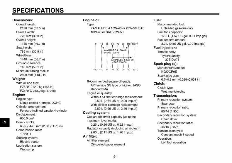
SPECIFICATIONS
9-1
9
Dimensions:Overall length:
2120 mm (83.5 in)Overall width:
770 mm (30.3 in)Overall height:
1185 mm (46.7 in)Seat height:
785 mm (30.9 in)Wheelbase:
1440 mm (56.7 in)Ground clearance:
140 mm (5.51 in)Minimum turning radius:
2800 mm (110.2 in)Weight:
With oil and fuel:FZ6RY 212.0 kg (467 lb)FZ6RYC 213.0 kg (470 lb)
Engine:Engine type:
Liquid cooled 4-stroke, DOHCCylinder arrangement:
Forward-inclined parallel 4-cylinderDisplacement:
600.0 cm³Bore × stroke:
65.5 × 44.5 mm (2.58 × 1.75 in)Compression ratio:
12.20 :1Starting system:
Electric starterLubrication system:
Wet sump
Engine oil:Type:
YAMALUBE 4 10W-40 or 20W-50, SAE 10W-40 or SAE 20W-50
Recommended engine oil grade:API service SG type or higher, JASO standard MA
Engine oil quantity:Without oil filter cartridge replacement:
2.50 L (2.64 US qt, 2.20 Imp.qt)With oil filter cartridge replacement:
2.80 L (2.96 US qt, 2.46 Imp.qt)Cooling system:
Coolant reservoir capacity (up to the maximum level mark):
0.25 L (0.26 US qt, 0.22 Imp.qt)Radiator capacity (including all routes):
2.00 L (2.11 US qt, 1.76 Imp.qt)Air filter:
Air filter element:Oil-coated paper element
Fuel:Recommended fuel:
Unleaded gasoline onlyFuel tank capacity:
17.3 L (4.57 US gal, 3.81 Imp.gal)Fuel reserve amount:
3.2 L (0.85 US gal, 0.70 Imp.gal)Fuel injection:
Throttle body:Type/quantity:
32EIDW/1Spark plug (s):
Manufacturer/model:NGK/CR9E
Spark plug gap:0.7–0.8 mm (0.028–0.031 in)
Clutch:Clutch type:
Wet, multiple-discTransmission:
Primary reduction system:Spur gear
Primary reduction ratio:86/44 (1.955)
Secondary reduction system:Chain drive
Secondary reduction ratio:46/16 (2.875)
Transmission type:Constant mesh 6-speed
Operation:Left foot operation
10 30 50 70 90 1100 130 ˚F
YAMALUBE 4 10W-40or SAE 10W-40
YAMALUBE 4 20W-50or SAE 20W-50
–10 0 10 20 30 40–20 50 ˚C
U36P10E0.book Page 1 Thursday, November 13, 2008 4:45 PM

SPECIFICATIONS
9-2
9
Gear ratio:1st:
37/13 (2.846)2nd:
37/19 (1.947)3rd:
28/18 (1.556)4th:
32/24 (1.333)5th:
25/21 (1.190)6th:
26/24 (1.083)Chassis:
Frame type:Diamond
Caster angle:26.00 °
Trail:103.5 mm (4.07 in)
Front tire:Type:
TubelessSize:
120/70 ZR17M/C (58W)Manufacturer/model:
BRIDGESTONE/BT021Manufacturer/model:
DUNLOP/ROADSMARTRear tire:
Type:Tubeless
Size:160/60 ZR17M/C (69W)
Manufacturer/model:BRIDGESTONE/BT021
Manufacturer/model:DUNLOP/ROADSMART
Loading:Maximum load:
FZ6RY 188 kg (414 lb)FZ6RYC 187 kg (412 lb)(Total weight of rider, passenger, cargo and accessories)
Tire air pressure (measured on cold tires):
Loading condition:0–90 kg (0–198 lb)Front:
225 kPa (2.25 kgf/cm², 33 psi)Rear:
250 kPa (2.50 kgf/cm², 36 psi)Loading condition:
FZ6RY 90–188 kg (198–414 lb)FZ6RYC 90–187 kg (198–412 lb)Front:
250 kPa (2.50 kgf/cm², 36 psi)Rear:
290 kPa (2.90 kgf/cm², 42 psi)High-speed riding:
Front:225 kPa (2.25 kgf/cm², 33 psi)
Rear:250 kPa (2.50 kgf/cm², 36 psi)
Front wheel:Wheel type:
Cast wheel
Rim size:17M/C x MT3.50
Rear wheel:Wheel type:
Cast wheelRim size:
17M/C x MT4.50Front brake:
Type:Dual disc brake
Operation:Right hand operation
Recommended fluid:DOT 4
Rear brake:Type:
Single disc brakeOperation:
Right foot operationRecommended fluid:
DOT 4Front suspension:
Type:Telescopic fork
Spring/shock absorber type:Coil spring/oil damper
Wheel travel:130.0 mm (5.12 in)
Rear suspension:Type:
Swingarm (monocross)Spring/shock absorber type:
Coil spring/gas-oil damper
U36P10E0.book Page 2 Thursday, November 13, 2008 4:45 PM
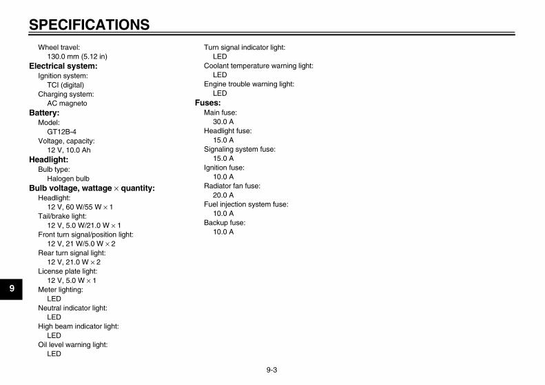
SPECIFICATIONS
9-3
9
Wheel travel:130.0 mm (5.12 in)
Electrical system:Ignition system:
TCI (digital)Charging system:
AC magnetoBattery:
Model:GT12B-4
Voltage, capacity:12 V, 10.0 Ah
Headlight:Bulb type:
Halogen bulbBulb voltage, wattage × quantity:
Headlight:12 V, 60 W/55 W × 1
Tail/brake light:12 V, 5.0 W/21.0 W × 1
Front turn signal/position light:12 V, 21 W/5.0 W × 2
Rear turn signal light:12 V, 21.0 W × 2
License plate light:12 V, 5.0 W × 1
Meter lighting:LED
Neutral indicator light:LED
High beam indicator light:LED
Oil level warning light:LED
Turn signal indicator light:LED
Coolant temperature warning light:LED
Engine trouble warning light:LED
Fuses:Main fuse:
30.0 AHeadlight fuse:
15.0 ASignaling system fuse:
15.0 AIgnition fuse:
10.0 ARadiator fan fuse:
20.0 AFuel injection system fuse:
10.0 ABackup fuse:
10.0 A
U36P10E0.book Page 3 Thursday, November 13, 2008 4:45 PM
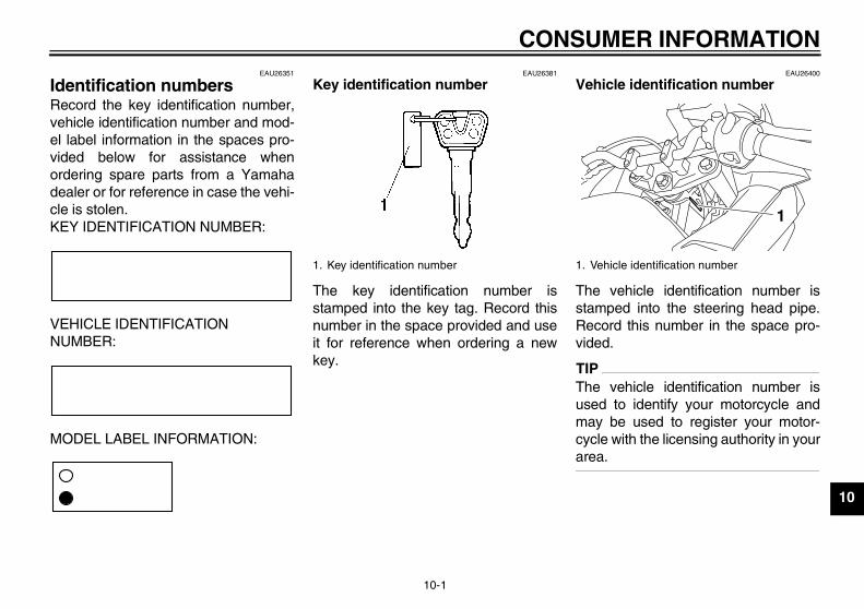
CONSUMER INFORMATION
10-1
10
EAU26351
Identification numbers Record the key identification number,vehicle identification number and mod-el label information in the spaces pro-vided below for assistance whenordering spare parts from a Yamahadealer or for reference in case the vehi-cle is stolen.KEY IDENTIFICATION NUMBER:
VEHICLE IDENTIFICATION NUMBER:
MODEL LABEL INFORMATION:
EAU26381
Key identification number
The key identification number isstamped into the key tag. Record thisnumber in the space provided and useit for reference when ordering a newkey.
EAU26400
Vehicle identification number
The vehicle identification number isstamped into the steering head pipe.Record this number in the space pro-vided.
TIPThe vehicle identification number isused to identify your motorcycle andmay be used to register your motor-cycle with the licensing authority in yourarea.
1. Key identification number 1. Vehicle identification number
1
U36P10E0.book Page 1 Thursday, November 13, 2008 4:45 PM
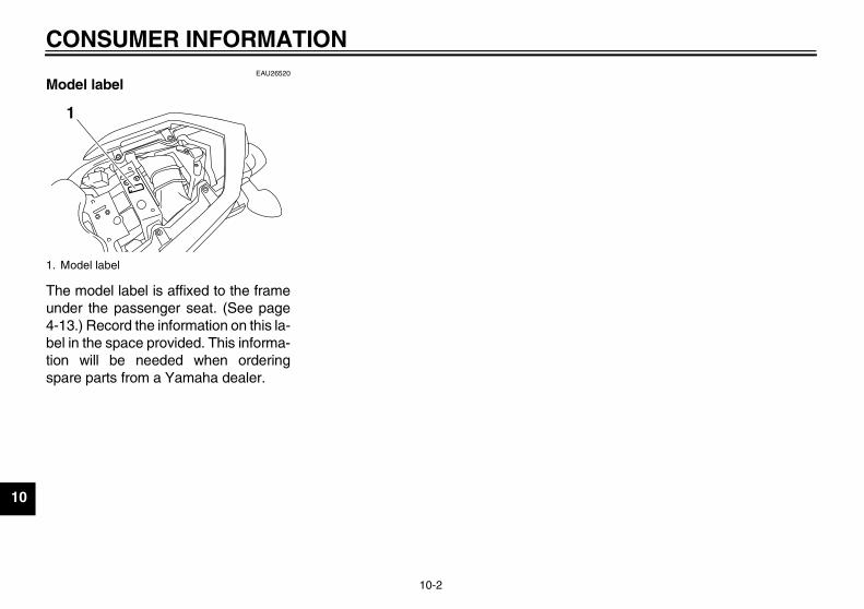
CONSUMER INFORMATION
10-2
10
EAU26520
Model label
The model label is affixed to the frameunder the passenger seat. (See page4-13.) Record the information on this la-bel in the space provided. This informa-tion will be needed when orderingspare parts from a Yamaha dealer.
1. Model label
1
U36P10E0.book Page 2 Thursday, November 13, 2008 4:45 PM
CONSUMER INFORMATION
10-3
10
EAU26551
Reporting safety defects If you believe that your vehicle has a defect which could cause a crash or could cause injury or death, you should immediatelyinform the National Highway Traffic Safety Administration (NHTSA) in addition to notifying Yamaha Motor Corporation,U.S.A. If NHTSA receives similar complaints, it may open an investigation, and if it finds that a safety defect exists in a groupof vehicles, it may order a recall and remedy campaign. However, NHTSA cannot become involved in individual problemsbetween you, your dealer, or Yamaha Motor Corporation, U.S.A.To contact NHTSA, you may call the Vehicle Safety Hotline toll-free at 1-888-327-4236 (TTY: 1-800-424-9153); go tohttp://www.safercar.gov; or write to: Administrator, NHTSA, 400 Seventh Street, SW., Washington, DC 20590. You can alsoobtain other information about motor vehicle safety from http://www.safercar.gov.
U36P10E0.book Page 3 Thursday, November 13, 2008 4:45 PM
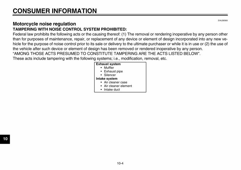
CONSUMER INFORMATION
10-4
10
EAU26560
Motorcycle noise regulation TAMPERING WITH NOISE CONTROL SYSTEM PROHIBITED:Federal law prohibits the following acts or the causing thereof: (1) The removal or rendering inoperative by any person otherthan for purposes of maintenance, repair, or replacement of any device or element of design incorporated into any new ve-hicle for the purpose of noise control prior to its sale or delivery to the ultimate purchaser or while it is in use or (2) the use ofthe vehicle after such device or element of design has been removed or rendered inoperative by any person.“AMONG THOSE ACTS PRESUMED TO CONSTITUTE TAMPERING ARE THE ACTS LISTED BELOW”.These acts include tampering with the following systems; i.e., modification, removal, etc.
Exhaust system• Muffler• Exhaust pipe• Silencer
Intake system• Air cleaner case• Air cleaner element• Intake duct
U36P10E0.book Page 4 Thursday, November 13, 2008 4:45 PM
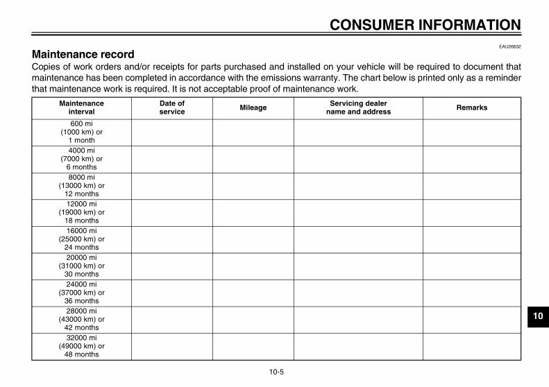
CONSUMER INFORMATION
10-5
10
EAU26632
Maintenance record Copies of work orders and/or receipts for parts purchased and installed on your vehicle will be required to document thatmaintenance has been completed in accordance with the emissions warranty. The chart below is printed only as a reminderthat maintenance work is required. It is not acceptable proof of maintenance work.
Maintenanceinterval
Date ofservice Mileage Servicing dealer
name and address Remarks
600 mi(1000 km) or
1 month4000 mi
(7000 km) or6 months8000 mi
(13000 km) or12 months12000 mi
(19000 km) or18 months16000 mi
(25000 km) or24 months20000 mi
(31000 km) or30 months24000 mi
(37000 km) or36 months28000 mi
(43000 km) or42 months32000 mi
(49000 km) or48 months
U36P10E0.book Page 5 Thursday, November 13, 2008 4:45 PM

CONSUMER INFORMATION
10-6
10
36000 mi(55000 km) or
54 months40000 mi
(61000 km) or60 months
Maintenanceinterval
Date ofservice Mileage Servicing dealer
name and address Remarks
U36P10E0.book Page 6 Thursday, November 13, 2008 4:45 PM
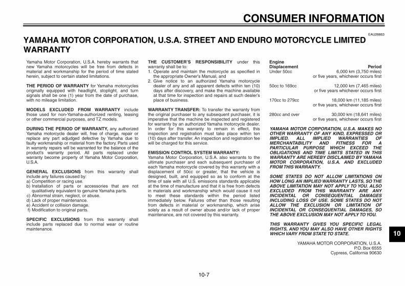
CONSUMER INFORMATION
10-7
10
EAU26663
YAMAHA MOTOR CORPORATION, U.S.A. STREET AND ENDURO MOTORCYCLE LIMITED WARRANTY
a)b)
c)d)e)f)
1.
2.
Yamaha Motor Corporation, U.S.A. hereby warrants that new Yamaha motorcycles will be free from defects in material and workmanship for the period of time stated herein, subject to certain stated limitations.
THE PERIOD OF WARRANTY for Yamaha motorcycles originally equipped with headlight, stoplight, and turn signals shall be one (1) year from the date of purchase, with no mileage limitation.
MODELS EXCLUDED FROM WARRANTY include those used for non-Yamaha-authorized renting, leasing or other commercial purposes, and TZ models.
DURING THE PERIOD OF WARRANTY, any authorized Yamaha motorcycle dealer will, free of charge, repair or replace any part adjudged defective by Yamaha due to faulty workmanship or material from the factory. Parts used in warranty repairs will be warranted for the balance of the product’s warranty period. All parts replaced under warranty become property of Yamaha Motor Corporation, U.S.A.
GENERAL EXCLUSIONS from this warranty shall include any failures caused by:
Competition or racing use.Installation of parts or accessories that are not qualitatively equivalent to genuine Yamaha parts.Abnormal strain, neglect, or abuse.Lack of proper maintenance.Accident or collision damage.Modification to original parts.
SPECIFIC EXCLUSIONS from this warranty shall include parts replaced due to normal wear or routine maintenance.
THE CUSTOMER’S RESPONSIBILITY under this warranty shall be to:
Operate and maintain the motorcycle as specified in the appropriate Owner’s Manual, andGive notice to an authorized Yamaha motorcycle dealer of any and all apparent defects within ten (10) days after discovery, and make the machine available at that time for inspection and repairs at such dealer’s place of business.
WARRANTY TRANSFER: To transfer the warranty from the original purchaser to any subsequent purchaser, it is imperative that the machine be inspected and registered for warranty by an authorized Yamaha motorcycle dealer. In order for this warranty to remain in effect, this inspection and registration must take place within ten (10) days after transfer. An inspection and registration fee will be charged for this service.
EMISSION CONTROL SYSTEM WARRANTY:Yamaha Motor Corporation, U.S.A. also warrants to the ultimate purchaser and each subsequent purchaser of each Yamaha motorcycle covered by this warranty with a displacement of 50cc or greater, that the vehicle is designed, built, and equipped so as to conform at the time of sale with all U.S. emissions standards applicable at the time of manufacture and that it is free from defects in materials and workmanship which would cause it not to meet these standards within the period listed immediately below. Failures other than those resulting from defects in material or workmanship, which arise solely as a result of owner abuse and/or lack of proper maintenance, are not covered by this warranty.
Period6,000 km (3,750 miles)
or five years, whichever occurs first
12,000 km (7,465 miles)or five years whichever occurs first
18,000 km (11,185 miles)or five years, whichever occurs first
30,000 km (18,641 miles)or five years, whichever occurs first
YAMAHA MOTOR CORPORATION, U.S.A. MAKES NO OTHER WARRANTY OF ANY KIND, EXPRESSED OR IMPLIED. ALL IMPLIED WARRANTIES OF MERCHANTABILITY AND FITNESS FOR A PARTICULAR PURPOSE WHICH EXCEED THE OBLIGATIONS AND TIME LIMITS STATED IN THIS WARRANTY ARE HEREBY DISCLAIMED BY YAMAHA MOTOR CORPORATION, U.S.A. AND EXCLUDED FROM THIS WARRANTY.
SOME STATES DO NOT ALLOW LIMITATIONS ON HOW LONG AN IMPLIED WARRANTY LASTS, SO THE ABOVE LIMITATION MAY NOT APPLY TO YOU. ALSO EXCLUDED FROM THIS WARRANTY ARE ANY INCIDENTAL OR CONSEQUENTIAL DAMAGES INCLUDING LOSS OF USE. SOME STATES DO NOT ALLOW THE EXCLUSION OR LIMITATION OF INCIDENTAL OR CONSEQUENTIAL DAMAGES, SO THE ABOVE EXCLUSION MAY NOT APPLY TO YOU.
THIS WARRANTY GIVES YOU SPECIFIC LEGAL RIGHTS, AND YOU MAY ALSO HAVE OTHER RIGHTS WHICH VARY FROM STATE TO STATE.
YAMAHA MOTOR CORPORATION, U.S.A.P.O. Box 6555
Cypress, California 90630
Engine Displacement Under 50cc
50cc to 169cc
170cc to 279cc
280cc and over
U36P10E0.book Page 7 Thursday, November 13, 2008 4:45 PM
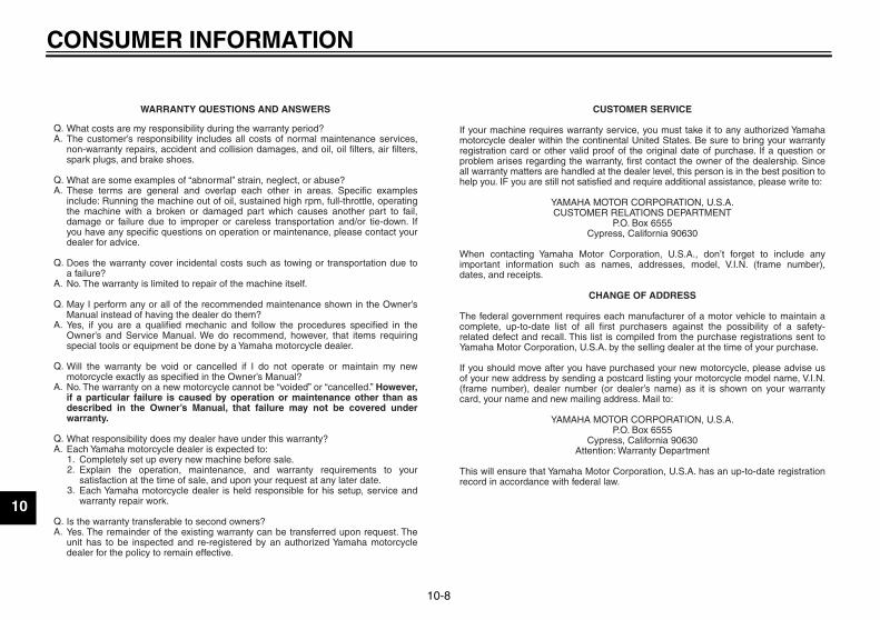
CONSUMER INFORMATION
10-8
10
WARRANTY QUESTIONS AND ANSWERS
What costs are my responsibility during the warranty period?The customer’s responsibility includes all costs of normal maintenance services, non-warranty repairs, accident and collision damages, and oil, oil filters, air filters, spark plugs, and brake shoes.
What are some examples of “abnormal” strain, neglect, or abuse?These terms are general and overlap each other in areas. Specific examples include: Running the machine out of oil, sustained high rpm, full-throttle, operating the machine with a broken or damaged part which causes another part to fail, damage or failure due to improper or careless transportation and/or tie-down. If you have any specific questions on operation or maintenance, please contact your dealer for advice.
Does the warranty cover incidental costs such as towing or transportation due toa failure?No. The warranty is limited to repair of the machine itself.
May I perform any or all of the recommended maintenance shown in the Owner’s Manual instead of having the dealer do them?Yes, if you are a qualified mechanic and follow the procedures specified in the Owner’s and Service Manual. We do recommend, however, that items requiring special tools or equipment be done by a Yamaha motorcycle dealer.
Will the warranty be void or cancelled if I do not operate or maintain my new motorcycle exactly as specified in the Owner’s Manual?No. The warranty on a new motorcycle cannot be “voided” or “cancelled.” However, if a particular failure is caused by operation or maintenance other than as described in the Owner’s Manual, that failure may not be covered under warranty.
What responsibility does my dealer have under this warranty?Each Yamaha motorcycle dealer is expected to:
Completely set up every new machine before sale.Explain the operation, maintenance, and warranty requirements to your satisfaction at the time of sale, and upon your request at any later date.Each Yamaha motorcycle dealer is held responsible for his setup, service and warranty repair work.
Is the warranty transferable to second owners?Yes. The remainder of the existing warranty can be transferred upon request. The unit has to be inspected and re-registered by an authorized Yamaha motorcycle dealer for the policy to remain effective.
CUSTOMER SERVICE
If your machine requires warranty service, you must take it to any authorized Yamaha motorcycle dealer within the continental United States. Be sure to bring your warranty registration card or other valid proof of the original date of purchase. If a question or problem arises regarding the warranty, first contact the owner of the dealership. Since all warranty matters are handled at the dealer level, this person is in the best position to help you. IF you are still not satisfied and require additional assistance, please write to:
YAMAHA MOTOR CORPORATION, U.S.A.CUSTOMER RELATIONS DEPARTMENT
P.O. Box 6555Cypress, California 90630
When contacting Yamaha Motor Corporation, U.S.A., don’t forget to include any important information such as names, addresses, model, V.I.N. (frame number), dates, and receipts.
CHANGE OF ADDRESS
The federal government requires each manufacturer of a motor vehicle to maintain a complete, up-to-date list of all first purchasers against the possibility of a safety-related defect and recall. This list is compiled from the purchase registrations sent to Yamaha Motor Corporation, U.S.A. by the selling dealer at the time of your purchase.
If you should move after you have purchased your new motorcycle, please advise us of your new address by sending a postcard listing your motorcycle model name, V.I.N. (frame number), dealer number (or dealer’s name) as it is shown on your warranty card, your name and new mailing address. Mail to:
YAMAHA MOTOR CORPORATION, U.S.A.P.O. Box 6555
Cypress, California 90630Attention: Warranty Department
This will ensure that Yamaha Motor Corporation, U.S.A. has an up-to-date registration record in accordance with federal law.
Q.A.
Q.A.
Q.
A.
Q.
A.
Q.
A.
Q.A.
1.2.
3.
Q.A.
U36P10E0.book Page 8 Thursday, November 13, 2008 4:45 PM
CONSUMER INFORMATION
10-9
10
EAU26750
YAMAHA EXTENDED SERVICE (Y.E.S.) Keep your Yamaha protected even after your warranty expires with genuine Yamaha Extended Service (Y.E.S.).
Y.E.S. is designed and administered by Yamaha Motor Corporation to provide maximum owner satisfaction. You get uninterrupted factory-backed coverage for extra peace of mind.
Y.E.S. is flexible. You choose the plan that’s right foryou: 12 months, 24 months, 36 months or, on certain models, even 48 months beyond your warranty period.
Y.E.S. is designed and administered by the same Yamaha people who handle your warranty – and itshows in the comprehensive coverage benefits. There are no mileage limitations. Coverage isn’t limited to “moving parts” or the “drive train” like many other plans. And Y.E.S. covers manufacturing defects just like the warranty. See the sample contract at your Yamahadealer to see how comforting uninterrupted factory-backed protection can be.
You don’t have to pay anything for covered repairs. There’s no deductible to pay, and repairs aren’t“pro-rated.” You don’t have any “out-of-pocket” expenses for covered repairs.
In addition, Travel and Recreation Interruption Protection (TRIP) is included at no extra cost. TRIP gives you up to $150 reimbursement per occurrence for any reasonable expenses you incur because your Yamaha needs covered service: replacement vehicle rental, emergency towing, phone calls, even food and lodging when you are away from home. This superb coverage goes into effect when you purchase Y.E.S., so it applies to any warranty repairs as well as covered repairs during your entire Y.E.S. plan period.
Y.E.S. coverage is honored at any authorized Yamaha dealer nationwide.
Y.E.S. coverage is transferable to a new owner if yousell or trade-in. That can make your Yamaha much more valuable!
This excellent Y.E.S. plan coverage is only available to Yamaha owners like you, and only while your Yamaha is still within the Yamaha Limited Warranty period. So visit your authorized Yamaha dealer to get all the facts. He can show you how easy it is to protect your investment with Yamaha Extended Service.
U36P10E0.book Page 9 Thursday, November 13, 2008 4:45 PM
CONSUMER INFORMATION
10-10
10
We urge you to act now. You’ll get the excellent benefits of TRIP coverage right away, and you’ll rest easy knowing you’ll have strong factory-backed protection even after your Yamaha Limited Warranty expires.
A special note:If visiting your dealer isn’t convenient, contact Yamaha with your Primary ID number (your frame number). We’ll be happy to help you get the Y.E.S. coverage you need.
Yamaha Service MarketingP.O. Box 6555Cypress, CA 906301-(866)-YES-EXTD (1-866-937-3983)
U36P10E0.book Page 10 Thursday, November 13, 2008 4:45 PM
INDEXA
Air filter element, replacing ................... 7-19B
Battery .................................................. 7-34Brake and clutch levers, checking and
lubricating ........................................... 7-31Brake and shift pedals, checking and
lubricating ........................................... 7-30Brake fluid, changing ............................ 7-27Brake fluid level, checking .................... 7-26Brake lever ........................................... 4-10Brake pedal .......................................... 4-10
CCables, checking and lubricating.......... 7-30Canister (for California only)................. 7-13Care........................................................ 8-1Catalytic converter................................ 4-13Clutch lever............................................. 4-9Clutch lever free play, adjusting ........... 7-24Coolant ................................................. 7-16Coolant temperature warning light.......... 4-3Cowlings and panels, removing and
installing ............................................... 7-9D
Dimmer switch ........................................ 4-9Drive chain, cleaning and lubricating.... 7-29Drive chain slack .................................. 7-28
EEngine break-in ...................................... 6-3Engine idling speed, checking .............. 7-21Engine oil and oil filter cartridge ........... 7-13Engine stop switch.................................. 4-9Engine trouble warning light ................... 4-5
FFront and rear brake pads, checking ....7-26Front fork, checking...............................7-32Fuel .......................................................4-11Fuel tank cap.........................................4-11Fuses, replacing....................................7-35
HHandlebar position, adjusting................4-18Handlebar switches.................................4-8Headlight bulb, replacing.......................7-36Helmet holder........................................4-17High beam indicator light.........................4-2Horn switch .............................................4-9
IIdentification numbers ...........................10-1Ignition circuit cut-off system.................4-20Indicator and warning lights ....................4-2
KKey identification number......................10-1
LLabels, location .......................................1-1License plate light bulb, replacing .........7-38
MMain switch/steering lock ........................4-1Maintenance and lubrication, periodic.....7-4Maintenance, emission control system ...7-3Maintenance record ..............................10-5Matte color, caution.................................8-1Model label............................................10-2Multi-function meter unit..........................4-5
NNeutral indicator light ..............................4-2Noise regulation ....................................10-4
OOil level warning light .............................. 4-2
PParking.................................................... 6-4Part locations .......................................... 3-1
RRear brake light switch, adjusting ......... 7-25Rear view mirrors.................................. 4-18Rider seat height, adjusting .................. 4-15
SSafety defects, reporting....................... 10-3Safety information................................... 2-1Seats..................................................... 4-13Shifting.................................................... 6-2Shift pedal............................................. 4-10Shock absorber assembly, adjusting .... 4-19Sidestand.............................................. 4-20Sidestand, checking and lubricating ..... 7-32Spark plugs, checking........................... 7-12Specifications.......................................... 9-1Starting the engine.................................. 6-1Start switch ............................................. 4-9Steering, checking ................................ 7-33Storage ................................................... 8-3Storage compartment ........................... 4-17Supporting the motorcycle .................... 7-39Swingarm pivots, lubricating ................. 7-32
TTail/brake light bulb, replacing .............. 7-37Throttle cable free play, checking ......... 7-21Throttle grip and cable, checking and
lubricating ........................................... 7-30Tires...................................................... 7-22Tool kit .................................................... 7-2
U36P10E0.book Page 1 Thursday, November 13, 2008 4:45 PM
INDEXTroubleshooting .................................... 7-42Troubleshooting charts ......................... 7-43Turn signal indicator light ........................ 4-2Turn signal light bulb, replacing ............ 7-38Turn signal switch ................................... 4-9
VValve clearance .................................... 7-21Vehicle identification number ................ 10-1
WWarranty, extended............................... 10-9Warranty, limited ................................... 10-7Wheel bearings, checking..................... 7-33Wheel (front) ......................................... 7-39Wheel (rear) .......................................... 7-40Wheels .................................................. 7-24
U36P10E0.book Page 2 Thursday, November 13, 2008 4:45 PM

U36P10E0.book Page 3 Thursday, November 13, 2008 4:45 PM
PRINTED IN JAPAN2008.11-4.2×1 CR
(E)
PRINTED ON RECYCLED PAPER YAMAHA MOTOR CO., LTD.
DIC183