Embed Size (px)
Citation preview
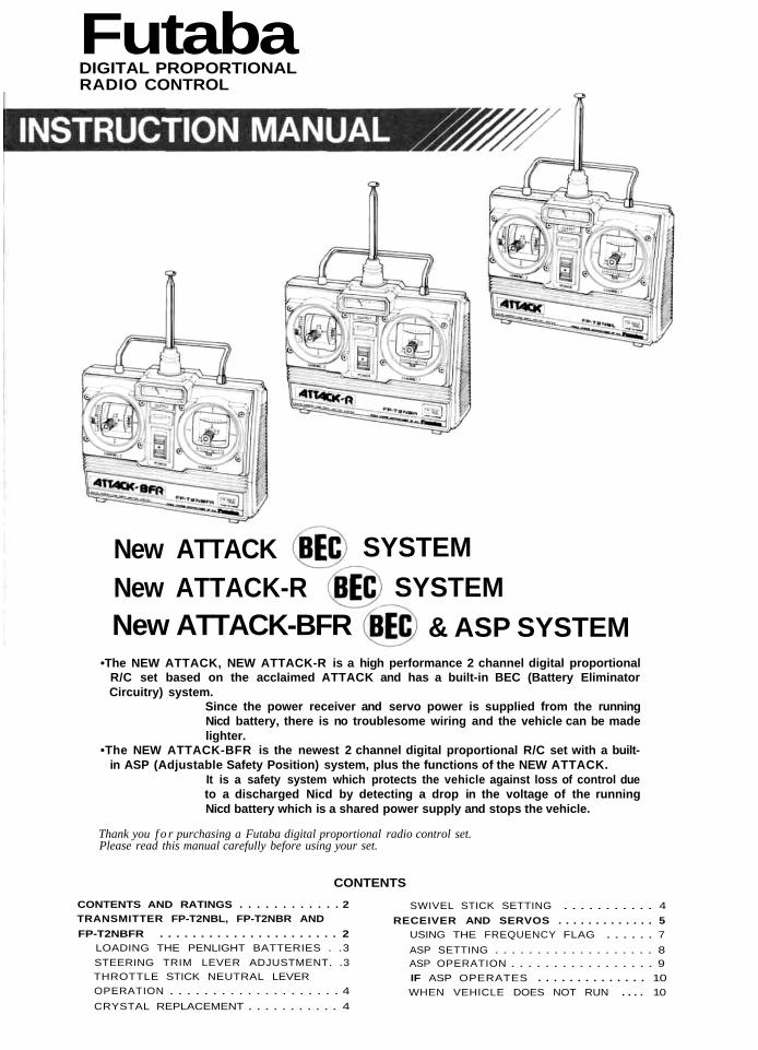
FutabaDIGITAL PROPORTIONALRADIO CONTROL
New ATTACK-BFR & ASP SYSTEMNew ATTACK-R SYSTEMNew ATTACK SYSTEM
•The NEW ATTACK, NEW ATTACK-R is a high performance 2 channel digital proportionalR/C set based on the acclaimed ATTACK and has a built-in BEC (Battery EliminatorCircuitry) system.
Since the power receiver and servo power is supplied from the runningNicd battery, there is no troublesome wiring and the vehicle can be madelighter.
•The NEW ATTACK-BFR is the newest 2 channel digital proportional R/C set with a built-in ASP (Adjustable Safety Position) system, plus the functions of the NEW ATTACK.
It is a safety system which protects the vehicle against loss of control dueto a discharged Nicd by detecting a drop in the voltage of the runningNicd battery which is a shared power supply and stops the vehicle.
Thank you f o r purchasing a Futaba digital proportional radio control set.Please read this manual carefully before using your set.
CONTENTSCONTENTS AND RATINGS . . . . . . . . . . . . 2TRANSMITTER FP-T2NBL, FP-T2NBR ANDFP-T2NBFR . . . . . . . . . . . . . . . . . . . . . . 2
LOADING THE PENLIGHT BATTERIES . .3STEERING TRIM LEVER ADJUSTMENT. .3THROTTLE STICK NEUTRAL LEVEROPERATION . . . . . . . . . . . . . . . . . . . . 4CRYSTAL REPLACEMENT . . . . . . . . . . . 4
SWIVEL STICK SETTING . . . . . . . . . . . 4RECEIVER AND SERVOS . . . . . . . . . . . . . 5
USING THE FREQUENCY FLAG . . . . . . 7ASP SETTING . . . . . . . . . . . . . . . . . . . 8ASP OPERATION . . . . . . . . . . . . . . . . . 9IF ASP OPERATES . . . . . . . . . . . . . . 10WHEN VEHICLE DOES NOT RUN . . . . 10
FEATURES OF NEW ATTACK NEW ATTACK-R AND NEW ATTACK-BFR
The NEW ATTACK, NEW ATTACK-R has a BEC function.The NEW ATTACK-BFR has BEC & ASP functions.
•The BEC (Battery Eliminator Circuitry) system is a high performance constant voltagecircuit (regulator). Since the running Nicd battery can also be used as the receiver servopower supply, there is no troublesome wiring and the vehicle can be made lighter.(Installed in NEW ATTACK, NEW ATTACK-R and NEW ATTACK-BFR.)
•The ASP (Adjustable Safety Position) system prevents loss of steering control. It is asafety system which protects the vehicle against loss of control due to a discharged Nicdby detecting a drop in the voltage of the shared power supply Nicd battery and auto-matically sets the throttle servo to the drive motor off position preset at the transmitterthen allows steering with the remaining power before steering control is lost. When thevoltage of the running Nicd battery recovers, ASP is automatically reset and the normalrunning functions are recovered by turning on the transmitter power switch. (Installedin NEW ATTACK-BPR)
World's first safety system that allows running of the vehicle up to the finishline while using the capacity of the power supply to the fullest without a loss ofsteering control even when the voltage of the running Nicd battery drops.
•Transmitter is Built-in servo reverse switches. (New ATTACK-R, NEW ATTACK-BFR)
TRANSMITTER FP-T2NBL/T2NBR/T2NBFR SERVO FP-S128SMALL, RUGGED, HIGH NEUTRAL SERVO
•ASP (Adjustable Safety Position) system allows saferecovery without a loss of steering control. (T2NBFRonly)
•New swivel stick system that allows selection of thestick lever operating direction over a range of 10°.
•Racing specification short aluminum stick lever makesoperation extremely easy.
•New neutral lever allows setting of the neutral positionof the throttle stick in two stages. Perfectly matched tothe throttle position of motor and engine cars. The stickcan be changed to a ratchet system by installing anoptional slider.
• Servo reverse switches (steering & throttle).Since each servo can be switched between forward andreverse from the outside of the transmitter, linkagehookup is extremely easy. (T2NBR, T2NBFR)
• Level meter shows the state of the battery at a glance.•Crystal can be changed from the outside. (Except 72.I
75MHz)• Hook. Optional neck strap can be used.
RECEIVER FP-R102GF
•BEC (Battery Eliminator Circuitry) system allowssharing of the running Nicd battery and eliminates theneed for a regulator and diode.
•High performance 2 channel receiver with ASP systemwhen used with the proper transmitter.
•Crystal socket uses a new type of highly reliable sub-miniature pins. Reliability is increased and the crystalcan be changed from the outside.
•Skew type armature motor.Movement of the trimmer by even one notch is trackedby a skew type motor which displays a performancenear that of a coreless motor.
• New indirect drive potentiometer improves vibrationand shock resistance and neutral accuracy.
• Futaba low-power custom 1C provides extremely hightorque, narrow dead band, and superior tracking.
• Fiberglass reinforced PBT (polybutylene terephthalate)injection molded servo case is mechanically strong andinvulnerable to glow fuel.
•Strong polyacetal resin ultra-precision servo gear fea-tures smooth operation, positive neutral, and very littlebacklash.
• Fiberglass reinforced epoxy resin PC board with thru-the-hole plating improves servo amp vibration and shockresistance.
• Three pin connector eliminates faulty contact and im-proves reliability against vibration and shock. Housinghas a reverse insertion prevention mechanism.
•Special grommet simplifies mounting of the servo andhas an excellent cushioning effect.
•Six special adjustable splined horns.•High 48.7oz.jn (3.5kg-cm) maximum output torque
allows use in almost any model.
1
CONTENTS AND RATINGS
Ratings are subject to change without prior notice.
Transmitter
Receiver
Servo
Battery holder
Others
FP-T2NBL x 1
FP-R102GFx 1
FP-S128x2
R2-BSS-N x 1
FP-T2NBR x 1
FP-R102GF x 1
FP-S128x2
R2-BSS-N x 1
FP-T2NBFR x 1
FP-R102GF x 1
FP-S128x 2
R2BSS-N x 1
Switch, frequency flag, spare horn
Transmitter FP-T2NBL/T2NBR T2NBFR
Operating systemTransmittingfrequencyModulationPower requirementCurrent drain
2 nick
27MHz, bands 1 to 6 72, 75MHz
AM (Amplitude Modulation)12.0V, penlight battery x 8170mA
Control systemOperating anglePowerrequirementCurrent drain(IDLE)Output torqueOperating speedDimensions
Weight
pulse width controlOne side 45° or more
4.8V -6
6.0V. 8mA (at Idle)
48.7 oz.in. 13.5 kg-cm)0.24 sec/601 6 x 0 8 x 1.6 in.(40.5 x 20 x 40.5mm)1.92oz. 153g)
SERVO FP-S128Receiver FP-R102GF
ReceivingfrequencyIntermediatefrequencySelectivityReceiving range
Power supply
Dimensions
Weight
27MHz band. bands 1 to 672. 75MHz
455kHz
3kHz/-3dB550 yards (500m) on the ground
when used with FP T2NBLIA1 thebest radio wave condition ofenvironment)4.8V to 8 4V7.2V/13mA. 4 8V/33mA1.46 x2.19x0.75 in(37 x 55.5 x 19mm)1.34 oz 138g)BEC & ASP functions
TRANSMITTER FP-T2NBL/T2NBR/T2NBFR
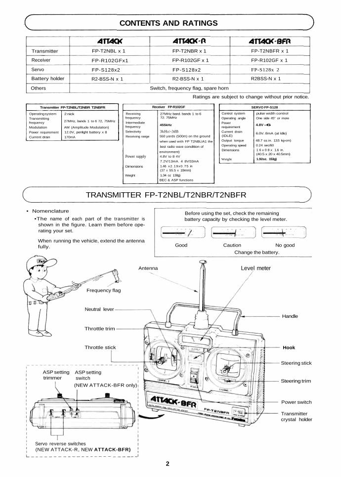
• Nomenclature•The name of each part of the transmitter is
shown in the figure. Learn them before ope-rating your set.
When running the vehicle, extend the antennafully.
Before using the set, check the remainingbattery capacity by checking the level meter.
Good Caution No goodChange the battery.
2
Servo reverse switches(NEW ATTACK-R, NEW ATTACK-BFR)
Handle
Level meterAntenna
Frequency flag
Neutral lever
Throttle trim
Throttle stick
ASP settingtrimmer
ASP settingswitch
(NEW ATTACK-BFR only)
Transmittercrystal holder
Power switch
Steering trim
Steering stick
Hook
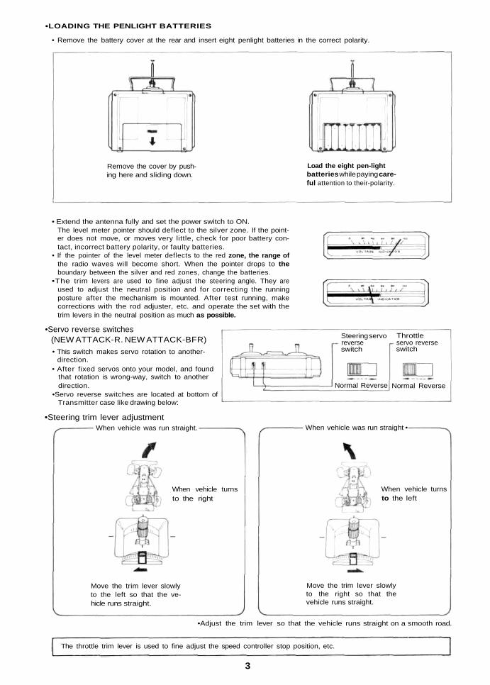
•LOADING THE PENLIGHT BATTERIES
• Remove the battery cover at the rear and insert eight penlight batteries in the correct polarity.
Remove the cover by push-ing here and sliding down.
Load the eight pen-lightbatteries while paying care-ful attention to their-polarity.
• Extend the antenna fully and set the power switch to ON.The level meter pointer should deflect to the silver zone. If the point-er does not move, or moves very little, check for poor battery con-tact, incorrect battery polarity, or faulty batteries.
• If the pointer of the level meter deflects to the red zone, the range ofthe radio waves will become short. When the pointer drops to theboundary between the silver and red zones, change the batteries.
•The trim levers are used to fine adjust the steering angle. They areused to adjust the neutral position and for correcting the runningposture after the mechanism is mounted. After test running, makecorrections with the rod adjuster, etc. and operate the set with thetrim levers in the neutral position as much as possible.
•Servo reverse switches(NEW ATTACK-R. NEW ATTACK-BFR)• This switch makes servo rotation to another-
direction.• After fixed servos onto your model, and found
that rotation is wrong-way, switch to anotherdirection.
•Servo reverse switches are located at bottom ofTransmitter case like drawing below:
•Steering trim lever adjustment
Normal Reverse Normal Reverse
Steering servoreverseswitch
Throttleservo reverseswitch
When vehicle was run straight •
When vehicle turnsto the right
Move the trim lever slowlyto the left so that the ve-hicle runs straight.
When vehicle turnsto the left
Move the trim lever slowlyto the right so that thevehicle runs straight.
When vehicle was run straight.
•Adjust the trim lever so that the vehicle runs straight on a smooth road.
The throttle trim lever is used to fine adjust the speed controller stop position, etc.
3
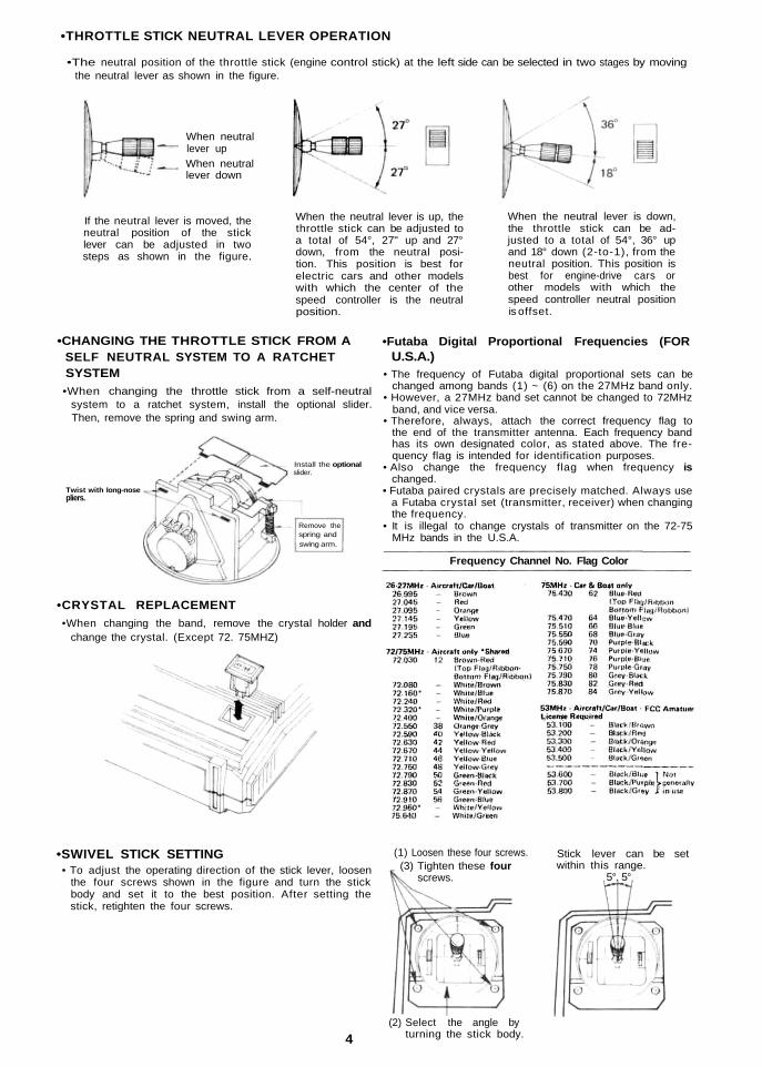
•THROTTLE STICK NEUTRAL LEVER OPERATION
•The neutral position of the throttle stick (engine control stick) at the left side can be selected in two stages by movingthe neutral lever as shown in the figure.
When neutrallever upWhen neutrallever down
If the neutral lever is moved, theneutral position of the sticklever can be adjusted in twosteps as shown in the figure.
When the neutral lever is up, thethrottle stick can be adjusted toa total of 54°, 27" up and 27°down, from the neutral posi-tion. This position is best forelectric cars and other modelswith which the center of thespeed controller is the neutralposition.
When the neutral lever is down,the throttle stick can be ad-justed to a total of 54°, 36° upand 18° down (2-to-1), from theneutral position. This position isbest for engine-drive cars orother models with which thespeed controller neutral positionis offset.
•CHANGING THE THROTTLE STICK FROM ASELF NEUTRAL SYSTEM TO A RATCHETSYSTEM•When changing the throttle stick from a self-neutral
system to a ratchet system, install the optional slider.Then, remove the spring and swing arm.
Twist with long-nosepliers.
Remove thespring andswing arm.
Install the optionalslider.
•CRYSTAL REPLACEMENT•When changing the band, remove the crystal holder and
change the crystal. (Except 72. 75MHZ)
•Futaba Digital Proportional Frequencies (FORU.S.A.)
• The frequency of Futaba digital proportional sets can bechanged among bands (1) ~ (6) on the 27MHz band only.
• However, a 27MHz band set cannot be changed to 72MHzband, and vice versa.
• Therefore, always, attach the correct frequency flag tothe end of the transmitter antenna. Each frequency bandhas its own designated color, as stated above. The fre-quency flag is intended for identification purposes.
• Also change the frequency flag when frequency ischanged.
• Futaba paired crystals are precisely matched. Always usea Futaba crystal set (transmitter, receiver) when changingthe frequency.
• It is illegal to change crystals of transmitter on the 72-75MHz bands in the U.S.A.
Frequency Channel No. Flag Color
•SWIVEL STICK SETTING• To adjust the operating direction of the stick lever, loosen
the four screws shown in the figure and turn the stickbody and set it to the best position. After setting thestick, retighten the four screws.
(1) Loosen these four screws.(3) Tighten these four
screws.
(2) Select the angle byturning the stick body.
Stick lever can be setwithin this range.
5°. 5°
4
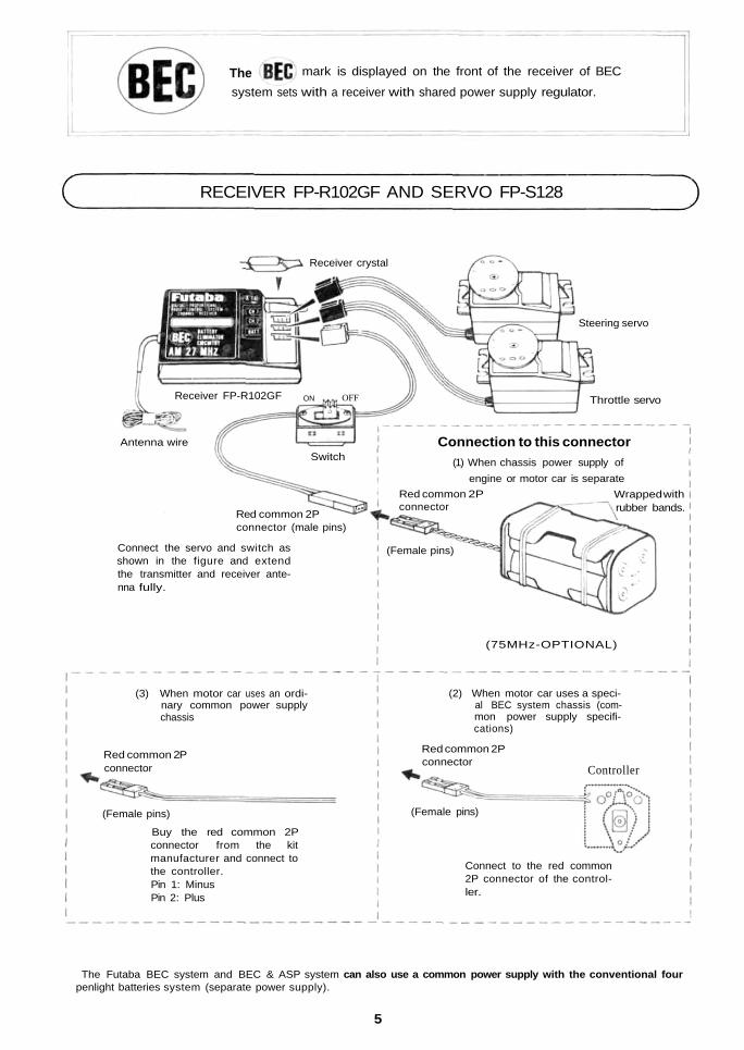
system sets with a receiver with shared power supply regulator.The mark is displayed on the front of the receiver of BEC
RECEIVER FP-R102GF AND SERVO FP-S128
The Futaba BEC system and BEC & ASP system can also use a common power supply with the conventional fourpenlight batteries system (separate power supply).
5
(75MHz-OPTIONAL)
(3) When motor car uses an ordi-nary common power supplychassis
Red common 2Pconnector
(Female pins)
Buy the red common 2Pconnector from the kitmanufacturer and connect tothe controller.Pin 1: MinusPin 2: Plus
(2) When motor car uses a speci-al BEC system chassis (com-mon power supply specifi-cations)
Connect to the red common2P connector of the control-ler.
Receiver crystal
Steering servo
Throttle servoReceiver FP-R102GF ON OFF
SwitchAntenna wire
Red common 2Pconnector (male pins)
Connect the servo and switch asshown in the figure and extendthe transmitter and receiver ante-nna fully.
(Female pins)
Red common 2Pconnector
Connection to this connector(1) When chassis power supply of
engine or motor car is separateWrapped withrubber bands.
(Female pins)
Controller
Red common 2Pconnector
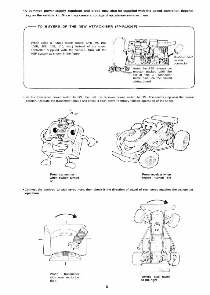
•A common power supply regulator and diode may also be supplied with the speed controller, depend-ing on the vehicle kit. Since they cause a voltage drop, always remove them.
TO BUYERS OF THE NEW ATTACK-BFR (FP-R102GF)
When using a Futaba motor control amp (MC-106,106B, 108, 109, 110, etc.) instead of the speedcontroller supplied with the vehicle, turn off theASP system as shown in the figure.
•Set the transmitter power switch to ON, then set the receiver power switch to ON. The servos stop near the neutralposition. Operate the transmitter sticks and check if each servo faithfully follows operation of the sticks.
R102GF ASPreleaseconnector
Insert the ASP release co-nnector packed with theset at this 2P connector '(male pins) on the printedwiring board.
From transmitterwhen switch turnedon
From receiver whenswitch turned off
• Connect the pushrod to each servo horn, then check if the direction of travel of each servo matches the transmitteroperation.
When transmitterstick lever set to theright
Vehicle also steersto the right
6
•Operate each servo over its full travel and check if the pushrod binds or is too loose. Applying unreasonable force tothe servo horn will adversely affect the servo and quickly drain the battery. Be especially careful when using 8.4V.
•Always make the full stroke (including trim) of the servo horns somewhat larger than the full travel. Adjust theservo horns so that they move smoothly even when the trim lever and stick are operated simultaneously in the samedirection.
• Be alert for noise.Always solder a noise killing capacitor to the running motor. If metal parts touch each other due to vibration, noisewill be generated and cause the receiver servos to operate erroneously. We recommend the use of noiseless parts.
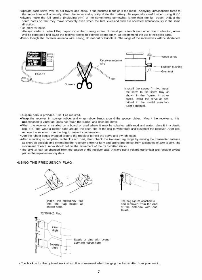
•Even though the receiver antenna wire is long, do not cut or bundle it. The range of the radiowaves will be shortened.
Receiver antennawire
Wood screw
Rubber bushing
Grommet
Install the servos firmly. Installthe servo to the servo tray asshown in the figure. In othercases, install the servo as des-cribed in the model manufac-turer's manual.
R 1 0 2 G F
Scissors
• A spare horn is provided. Use it as required.•Wrap the receiver in sponge rubber and wrap rubber bands around the sponge rubber. Mount the receiver so it is
not exposed to vibration, does not touch the frame, and does not move.•When the receiver is installed on a board or used where it may be splashed with mud and water, place it in a plastic
bag, etc. and wrap a rubber band around the open end of the bag to waterproof and dustproof the receiver. After use,remove the receiver from the bag to prevent condensation.
• Use the rubber bands wrapped around the receiver to hold the servo and switch leads.•After mounting is complete, recheck each part, then check the transmitting range by making the transmitter antenna
as short as possible and extending the receiver antenna fully and operating the set from a distance of 20m to 30m. Themovement of each servo should follow the movement of the transmitter sticks.
• The crystal can be changed from the outside of the receiver case. Always use a Futaba transmitter and receiver crystalpair as the replacement crystals.
•USING THE FREQUENCY FLAG
Insert the frequency flaginto the flag holder asshown here.
72/75MHZ Flag
Staple or glue with cyano-acrylate ribbon here.
The flag can be attached toand removed from the endof the antenna with onetouch.
• The hook is for the optional neck strap. It is convenient when hanging the transmitter from your neck.
7
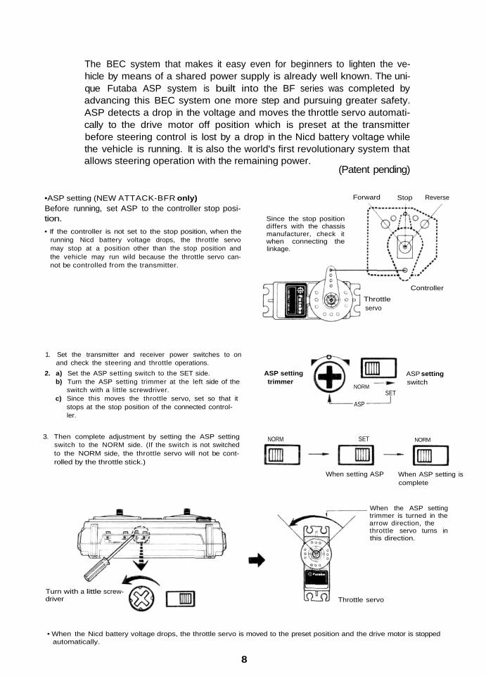
The BEC system that makes it easy even for beginners to lighten the ve-hicle by means of a shared power supply is already well known. The uni-que Futaba ASP system is built into the BF series was completed byadvancing this BEC system one more step and pursuing greater safety.ASP detects a drop in the voltage and moves the throttle servo automati-cally to the drive motor off position which is preset at the transmitterbefore steering control is lost by a drop in the Nicd battery voltage whilethe vehicle is running. It is also the world's first revolutionary system thatallows steering operation with the remaining power.
(Patent pending)
•ASP setting (NEW ATTACK-BFR only)Before running, set ASP to the controller stop posi-tion.• If the controller is not set to the stop position, when the
running Nicd battery voltage drops, the throttle servomay stop at a position other than the stop position andthe vehicle may run wild because the throttle servo can-not be controlled from the transmitter.
Forward Stop Reverse
Since the stop positiondiffers with the chassismanufacturer, check itwhen connecting thelinkage.
Throttleservo
Controller
1. Set the transmitter and receiver power switches to onand check the steering and throttle operations.
2. a) Set the ASP setting switch to the SET side. ASP settingb) Turn the ASP setting trimmer at the left side of the trimmer
switch with a little screwdriver.c) Since this moves the throttle servo, set so that it
stops at the stop position of the connected control-ler.
ASP settingswitch
NORMSET
ASP
3. Then complete adjustment by setting the ASP settingswitch to the NORM side. (If the switch is not switchedto the NORM side, the throttle servo will not be cont-rolled by the throttle stick.)
NORM SET NORM
When setting ASP When ASP setting iscomplete
Turn with a little screw-driver
When the ASP settingtrimmer is turned in thearrow direction, thethrottle servo turns inthis direction.
Throttle servo
• When the Nicd battery voltage drops, the throttle servo is moved to the preset position and the drive motor is stoppedautomatically.
8
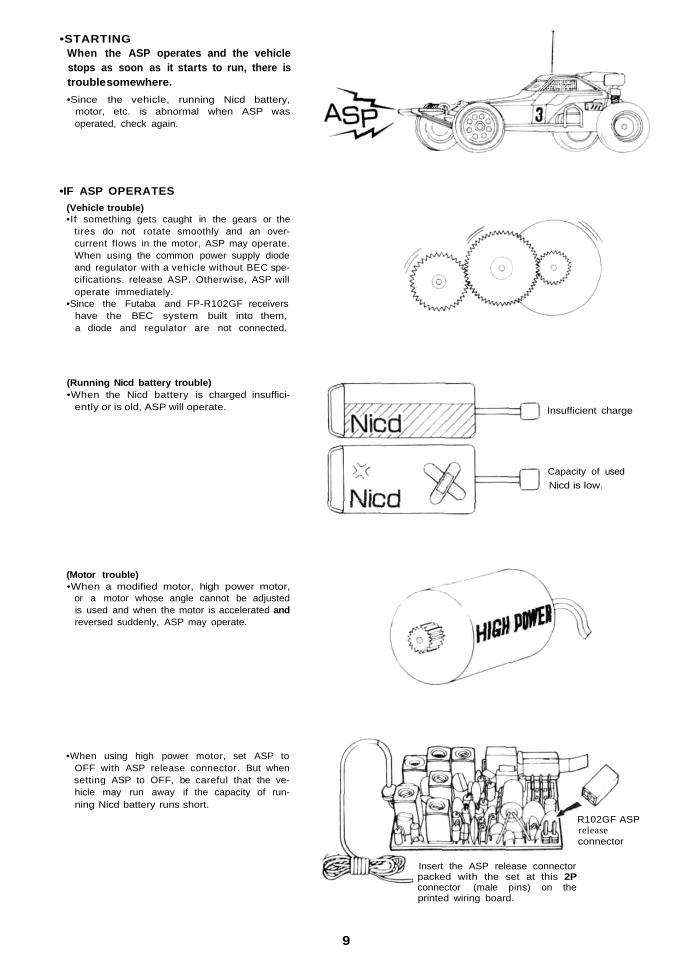
•STARTINGWhen the ASP operates and the vehiclestops as soon as it starts to run, there istrouble somewhere.•Since the vehicle, running Nicd battery,
motor, etc. is abnormal when ASP wasoperated, check again.
•IF ASP OPERATES(Vehicle trouble)•If something gets caught in the gears or the
tires do not rotate smoothly and an over-current flows in the motor, ASP may operate.When using the common power supply diodeand regulator with a vehicle without BEC spe-cifications. release ASP. Otherwise, ASP willoperate immediately.
•Since the Futaba and FP-R102GF receivershave the BEC system built into them,a diode and regulator are not connected.
(Running Nicd battery trouble)•When the Nicd battery is charged insuffici-
ently or is old, ASP will operate. Insufficient charge
Capacity of usedNicd is low.
(Motor trouble)•When a modified motor, high power motor,
or a motor whose angle cannot be adjustedis used and when the motor is accelerated andreversed suddenly, ASP may operate.
•When using high power motor, set ASP toOFF with ASP release connector. But whensetting ASP to OFF, be careful that the ve-hicle may run away if the capacity of run-ning Nicd battery runs short.
R102GF ASPreleaseconnector
Insert the ASP release connectorpacked with the set at this 2Pconnector (male pins) on theprinted wiring board.
9
•IF ASP OPERATES• If ASP system operates and the vehicle stops. Set to OFF once
set the transmitter power switch to OFFonce and set it to ON again. Then ASP systemstops working and you can start again.
• Restart running time depends on the varietyand condition of vehicle, motor, and battery.Be careful about that.
ON
OFF
Set to ON again.
•WHEN VEHICLE WILL NOT BE USEDBe sure and release the connector of runningNicd battery except when you are on the wayto the starting line.
When not using theconnector, set theswitch to OFF. Release the connector.
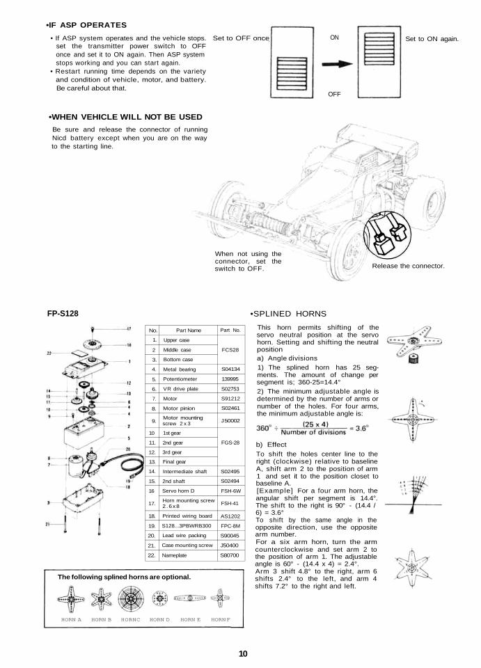
FP-S128
No.
1.
2
3.
4.
5.
6.
7.
8.
9.
10
11.
12.
13.
14.
15.
16
17.
18.
19.
20.
21.
22.
Part Name
Upper case
Middle case
Bottom case
Metal bearing
Potentiometer
VR drive plate
Motor
Motor pinion
Motor mountingscrew 2 x 3
1st gear
2nd gear
3rd gear
Final gear
Intermediate shaft
2nd shaft
Servo horn D
Horn mounting screw2 .6x8
Printed wiring board
S128...3PBWRB300
Lead wire packing
Case mounting screw
Nameplate
Part No.
FCS28
S04134
139995
S02753
S91212
S02461
J 50002
FGS-28
S02495
S02494
FSH-6W
FSH-41
AS1202
FPC-8M
S90045
J50400
S80700
The following splined horns are optional.
HORN A HORN B HORNC HORN D HORN E HORN F
•SPLINED HORNS
This horn permits shifting of theservo neutral position at the servohorn. Setting and shifting the neutralpositiona) Angle divisions1) The splined horn has 25 seg-ments. The amount of change persegment is; 360-25=14.4°2) The minimum adjustable angle isdetermined by the number of arms ornumber of the holes. For four arms,the minimum adjustable angle is:
b) EffectTo shift the holes center line to theright (clockwise) relative to baselineA, shift arm 2 to the position of arm1 and set it to the position closet tobaseline A.[Example] For a four arm horn, theangular shift per segment is 14.4°.The shift to the right is 90° - (14.4 /6) = 3.6°To shift by the same angle in theopposite direction, use the oppositearm number.For a six arm horn, turn the armcounterclockwise and set arm 2 tothe position of arm 1. The adjustableangle is 60° - (14.4 x 4) = 2.4°.Arm 3 shift 4.8° to the right, arm 6shifts 2.4° to the left, and arm 4shifts 7.2° to the right and left.
10
Your NEW FUTABA Digital Proportional R/C systemis guaranteed against defects in workmanship andmaterial for 180 days from the date of purchase whenthe attached registration card is returned to us withinten days of purchase.
This Guarantee is null and void if the R/C system hasbeen improperly handled, damaged in a crash, ortampered with and does not cover the replacement ofplastic housings or electronic components damageddue to the use of improper voltages.
When service is required, please take your equipmentto your local authorized service station or ship itdirectly to us. All postage, shipping, and insurancecharges must be paid by the user.
•When requesting repair of trouble that has occurredsuddenly of from long use, describe the troublesymptoms in as much detail as possible.This will facilitate detection of the trouble point andshorten the repair period greatly.
•Defects caused by faulty materials or workmanshipwill be corrected free of charge.
•This limited warranty is null and void if the set hasbeen tampered with or disassembled.Refer to warranty statement for details.
WORLD SALES & SERVICE FACILITIES
Australia: FUTABA SALES AUSTRALIA PTY. LTD., Lebanon:MELBOURNE TEL: 211-4788
Argentine: MODE LISMO AERONAUTICO DEGA SRL. New Zealand:BUENOS AIRES TEL: 393-2299
Canada: UDISCO LTD., MONTREALTEL: 481-8109 Norway:
Chile: HOBBY LANDIA, SANTIAGOTEL: 743957 Singapore:
Denmark: FUTABA IMPORT DENMARK,COPENHAGEN TEL: 02-91-0101 South Africa:
England: RIPMAX LIMITED, LONDONTEL: 01-8048272 Spain:
Finland: NORETRON KY. HELSINKITEL: 90-488880 Sweden:
Greece: C. & G. MACRIYIANNIS CO., PIRAEUSTEL: 021-3604 391 • or 021-41 76191 U.S.A.:
Hong Kong: RADAR CO. LTD. TEL: 3-680507Italy: RADIOSISTEMI SRL, Carrara W.Germany:
TLX: 500494 FORTIMIFAX: 0039-585-52247
KHAIRALLAH MODELCRAFT, BEIRUTTEL: 326-681AMALGAMATED WIRELESS(AUSTRALIA) N.Z. LTD. WELLINGTONTEL: 58-979HARALD LYCHE CO. A/S, DrammenTEL: (03) 833970SINGAPORE HOBBY SUPPLIESTEL: 533-0337REDIPAK (PTY.) LTD.,JOHANNESBURG TEL: 21-1511HOBBY & TOY INTERNATIONAL,VALENCIA TEL: (96) 357 23 93RADIO CONTROL CENTER,JONKOPING TEL: 036-145360FUTABA CORPORATION OF AMERICA,CALIFORNIA TEL: 213-537-9610ROBBE MODELLSPORT GMBH,GREBENHAIN TEL: 06644-870
FUTABA CORPORATION OF AMERICA
555 West Victoria Street Compton, California 90220 U.S.A.Phone: (213) 537-9610 Telex: 23-0691227 Facsimile: 213-637-8529
FUTABA CORPORATION
Tokyo Office: INAGAKI BLDG., 3F 1-21-3, Kandasudacho, Chiyoda-ku,Tokyo,Japan.
Phone: (03) 255-6811