Embed Size (px)
Citation preview
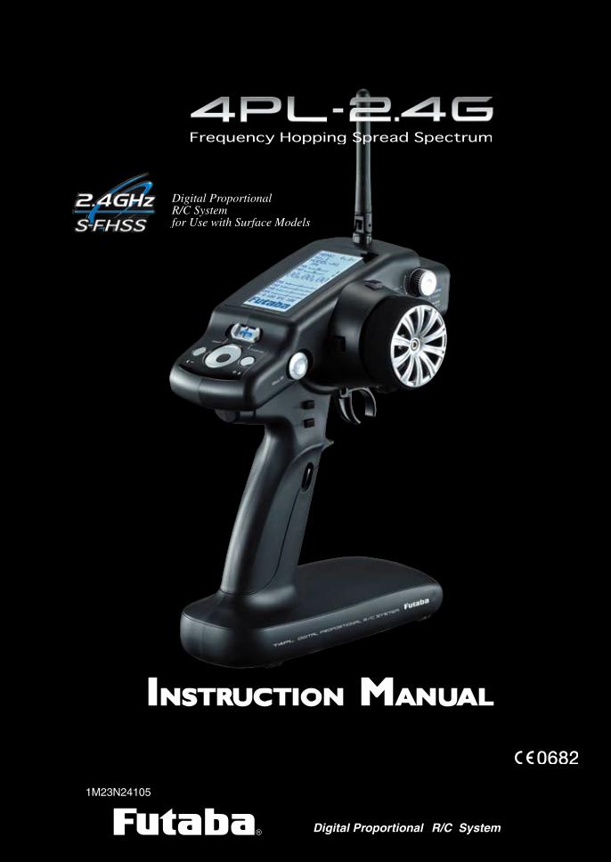
R Digital Proportional
1M23N24105
R/C SystemR
INSTRUCTION MANUAL
2
Thank you for purchasing a Futaba 4PL-2.4GHz system.Before using your 4PL-2.4GHz system, read this manual carefully in order to use
your R/C set safely.After reading this manual, store it in a safe place.
Application, Export, and Modification1. This product may be used for models only. It is not intended for use in any application other than the control of models for hobby and recreational purposes.
2. Exportation precautions:(a) When this product is exported from the country of manufacture, its use is to be approved by the laws governing the country of destination for devices that emit radio frequencies. If this product is then re-exported to other countries, it may be subject to restrictions on such export. Prior approval of the appropriate government authorities may be required. If you have purchased this product from an exporter outside your country, and not the authorized Futaba distributor in your country, please contact the seller immediately to determine if such export regulations have been met.(b) Use of this product with other than models may be restricted by Export and Trade Control Regulations, and an application for export approval must be submitted.
3. Modification, adjustment, and replacement of parts: Futaba is not responsible for un-authorized modification, adjustment, and replacement of parts on this product. Any such changes may void the warranty.
Compliance Information Statement (for U.S.A.)This device, trade name Futaba Corporation of America, model number R2104GF, com-plies with part 15 of the FCC Rules. Operation is subject to the following two condi-tions:(1) This device may not cause harmful interference.(2) This device must accept any interference received, including interference that may cause undesired operation.The responsible party for the compliance of this device is:Futaba Service Center3002 N Apollo Drive Suite 1, Champaign, IL 61822 U.S.A.TEL (217)398-8970 or E-mail: [email protected] (Support)TEL (217)398-0007 or E-mail: [email protected] (Service)
3
• No part of this manual may be reproduced in any form without prior permission.• The contents of this manual are subject to change without prior notice.• This manual has been carefully written. Please write to Futaba if you feel that any corrections or clarifica-
tions should be made.• Futaba is not responsible for the use of this product.
Battery Recycling (for U.S.A.)The RBRC™ SEAL on the (easily removable) nickel-cadmium battery and nickel-metal-hydride battery contained in Futaba products indicates that Futaba Corporation of America is voluntarily participating in an in-dustry program to collect and recycle these batteries at the end of their useful lives, when taken out of service within the United States. The
RBRC™ program provides a convenient alternative to placing used nickel-cadmium batteries and nickel-metal-hydride batteries into the trash or municipal waste system, which is illegal in some areas.You may contact your local recycling center for information on where to return the spent battery. Please call 1-800-8-BATTERY for information on NiCd/NiMH battery recycling in your area. Futaba Corporation of America's involvement in this program is part of its commitment to protecting our environment and conserving natural re-sources.
NOTE: Our instruction manuals encourage our customers to return spent batteries to a local recycling center in order to keep a healthy environment.RBRC™ is a trademark of the Rechargeable Battery Recycling Corporation.
4
Table Of Contents
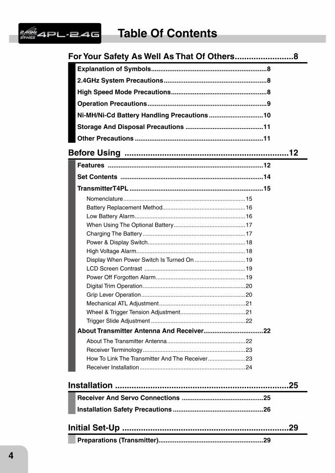
For Your Safety As Well As That Of Others .........................8Explanation of Symbols ................................................................8
2.4GHz System Precautions .........................................................8
High Speed Mode Precautions .....................................................8
Operation Precautions ..................................................................9
Ni-MH/Ni-Cd Battery Handling Precautions ..............................10
Storage And Disposal Precautions ...........................................11
Other Precautions .......................................................................11
Installation ..........................................................................25Receiver And Servo Connections .............................................25
Installation Safety Precautions ..................................................26
Before Using ......................................................................12Features ......................................................................................12
Set Contents ...............................................................................14
TransmitterT4PL ..........................................................................15
Nomenclature ...........................................................................15
Battery Replacement Method...................................................16
Low Battery Alarm ....................................................................16
When Using The Optional Battery ............................................17
Charging The Battery ...............................................................17
Power & Display Switch ............................................................18
High Voltage Alarm ...................................................................18
Display When Power Switch Is Turned On ...............................19
LCD Screen Contrast ..............................................................19
Power Off Forgotten Alarm .......................................................19
Digital Trim Operation ...............................................................20
Grip Lever Operation ................................................................20
Mechanical ATL Adjustment .....................................................21
Wheel & Trigger Tension Adjustment ........................................21
Trigger Slide Adjustment ..........................................................22
About Transmitter Antenna And Receiver.................................22
About The Transmitter Antenna ................................................22
Receiver Terminology ...............................................................23
How To Link The Transmitter And The Receiver .......................23
Receiver Installation .................................................................24
Initial Set-Up .......................................................................29Preparations (Transmitter) ..........................................................29
5
BeforeUsing
FunctionMap
Functions
For Your SafetyAs Well As
That Of Others
Installation
Reference
InitialSet-Up
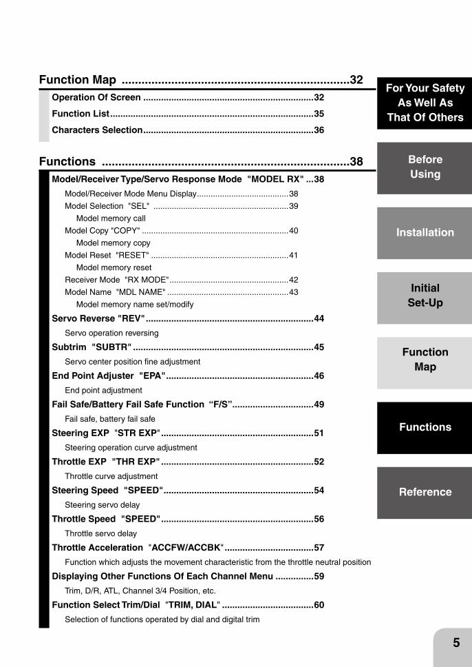
Function Map .....................................................................32Operation Of Screen ...................................................................32
Function List ................................................................................35
Characters Selection ...................................................................36
Functions ...........................................................................38Model/Receiver Type/Servo Response Mode "MODEL RX" ...38
Model/Receiver Mode Menu Display ........................................38
Model Selection "SEL" ...........................................................39
Model memory call
Model Copy "COPY" ................................................................40
Model memory copy
Model Reset "RESET" ............................................................41
Model memory reset
Receiver Mode "RX MODE" ....................................................42
Model Name "MDL NAME" .....................................................43
Model memory name set/modify
Servo Reverse "REV" ..................................................................44
Servo operation reversing
Subtrim "SUBTR" .......................................................................45
Servo center position fine adjustment
End Point Adjuster "EPA" ..........................................................46
End point adjustment
Fail Safe/Battery Fail Safe Function “F/S” ................................49
Fail safe, battery fail safe
Steering EXP "STR EXP" ............................................................51
Steering operation curve adjustment
Throttle EXP "THR EXP" ............................................................52
Throttle curve adjustment
Steering Speed "SPEED" ...........................................................54
Steering servo delay
Throttle Speed "SPEED" ............................................................56
Throttle servo delay
Throttle Acceleration "ACCFW/ACCBK" ...................................57
Function which adjusts the movement characteristic from the throttle neutral position
Displaying Other Functions Of Each Channel Menu ...............59
Trim, D/R, ATL, Channel 3/4 Position, etc.
Function Select Trim/Dial "TRIM, DIAL" ....................................60
Selection of functions operated by dial and digital trim
6
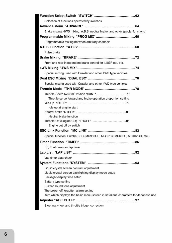
Function Select Switch "SWITCH" ............................................62
Selection of functions operated by switches
Advance Menu "ADVANCE" .......................................................64
Brake mixing, 4WS mixing, A.B.S, neutral brake, and other special functions
Programmable Mixing "PROG MIX" ..........................................66
Programmable mixing between arbitrary channels
A.B.S. Function "A.B.S" .............................................................68
Pulse brake
Brake Mixing "BRAKE" ..............................................................72
Front and rear independent brake control for 1/5GP car, etc.
4WS Mixing "4WS MIX"...............................................................74
Special mixing used with Crawler and other 4WS type vehicles
Dual ESC Mixing "DUAL ESC" ...................................................76
Special mixing used with Crawler and other 4WD type vehicles
Throttle Mode "THR MODE" ......................................................78
Throttle Servo Neutral Position "SXNT" ...................................78
Throttle servo forward and brake operation proportion setting
Idle-Up "IDLUP" ......................................................................79
Idle up at engine start
Neutral brake "NTBRK" ............................................................80
Neutral brake function
Throttle Off (Engine Cut) "THOFF" .........................................81
Engine cut off by switch
ESC Link Function "MC LINK" ...................................................82
Special function, Futaba ESC (MC950CR, MC851C, MC602C, MC402CR, etc.)
Timer Function "TIMER" ............................................................86
Up, Fuel down, or lap timer
Lap List "LAP LIST" ...................................................................92
Lap timer data check
System Functions "SYSTEM" ...................................................93
Liquid crystal screen contrast adjustment
Liquid crystal screen backlighting display mode setup
Backlight display time setup
Battery type setting
Buzzer sound tone adjustment
The power off forgotten alarm setting
Item which displays the basic menu screen in katakana characters for Japanese use
Adjuster "ADJUSTER" ................................................................97
Steering wheel and throttle trigger correction
7
BeforeUsing
FunctionMap
Functions
For Your SafetyAs Well As
That Of Others
Installation
Reference
InitialSet-Up
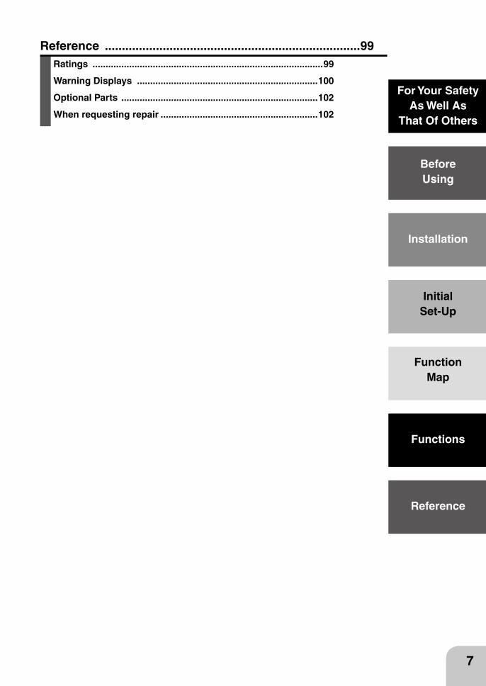
Reference ...........................................................................99Ratings ........................................................................................99
Warning Displays .....................................................................100
Optional Parts ...........................................................................102
When requesting repair ............................................................102
Warning
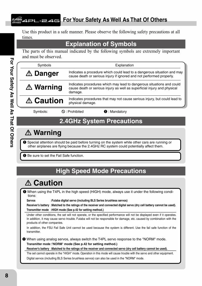
Caution When using the T4PL in the high speed (HIGH) mode, always use it under the following condi-tions:
Servos :Futaba digital servo (including BLS Series brushless servos) Receiver’s battery :Matched to the ratings of the receiver and connected digital servo (dry cell battery cannot be used).Transmitter mode :HIGH mode (See p.42 for setting method.)
Under other conditions, the set will not operate, or the specified performance will not be displayed even if it operates. In addition, it may cause servo trouble. Futaba will not be responsible for damage, etc. caused by combination with the products of other companies.
In addition, the FSU Fail Safe Unit cannot be used because the system is different. Use the fail safe function of the transmitter.
When using analog servos, always switch the T4PL servo response to the "NORM" mode.Transmitter mode :"NORM" mode (See p.42 for setting method.)Receiver’s battery :Matched to the ratings of the receiver and connected servo (dry cell battery cannot be used).The set cannot operate in the "HIGH" mode. Operation in this mode will cause trouble with the servo and other equipment.
Digital servos (including BLS Series brushless servos) can also be used in the "NORM" mode.
8
For Your Safety A
s Well A
s That Of O
thers
For Your Safety As Well As That Of Others
Use this product in a safe manner. Please observe the following safety precautions at all times.
Explanation of SymbolsThe parts of this manual indicated by the following symbols are extremely important and must be observed.
Danger Indicates procedures which may lead to dangerous situations and could
cause death or serious injury as well as superficial injury and physical damage.
Indicates procedures that may not cause serious injury, but could lead to physical damage.
Symbols: : Prohibited : Mandatory
Indicates a procedure which could lead to a dangerous situation and may cause death or serious injury if ignored and not performed properly.
Warning
Caution
Symbols Explanation
2.4GHz System Precautions
Special attention should be paid before turning on the system while other cars are running or other airplanes are flying because the 2.4GHz RC system could potentially affect them.
Be sure to set the Fail Safe function.
High Speed Mode Precautions
Warning
9
For
Your
Saf
ety
As
Wel
l As
That
Of O
ther
s
Do not operate outdoors on rainy days, run through puddles of water or use when visibility is limited.Should any type of moisture (water or snow) enter any component of the system, erratic operation and loss of control may occur.
Do not operate in the following places.-Near other sites where other radio control activity may occur.-Near people or roads.-On any pond when passenger boats are present.-Near high tension power lines or communication broadcasting antennas.
Interference could cause loss of control. Improper installation of your Radio Control System in your model could result in serious injury.
Operation Precautions
Do not operate this R/C system when you are tired, not feeling well or under the influence of alcohol or drugs.
Your judgment is impaired and could result in a dangerous situation that may cause serious injury to yourself as well as others.
Do not touch the engine, motor, speed control or any part of the model that will generate heat while the model is operating or immediately after its use.
These parts may be very hot and can cause serious burns.
Always perform an operating range check prior to use.Problems with the radio control system as well as improper installation in a model could cause loss of control. (Simple range test method)Have a friend hold the model, or clamp it down or place it where the wheels or prop cannot come in contact with any object. Walk away and check to see if the servos follow the movement of the controls on the transmitter. Should you notice any abnormal operation, do not operate the model. Also check to be sure the model memory matches the model in use.
Turning on the power switches. Always check the throttle trigger on the transmitter to be sure it is at the neutral position.
1. Turn on the transmitter power switch.
2. Turn on the receiver or speed control power switch.
Turning off the power switches Always be sure the engine is not running or the motor is stopped.
1. Turn off the receiver or speed control power switch.
2. Then turn off the transmitter power switch.
If the power switches are turned off in the opposite order, the model may unexpectedly run out of control and cause a very dangerous situation.
When making adjustments to the model, do so with the engine not running or the motor discon-nected.
You may unexpectedly lose control and create a dangerous situation.
Caution
Warning
Caution
10
For Your Safety A
s Well A
s That Of O
thers
(Only when NiMH/NiCd batteries are used)NiMH / NiCd Battery Handling Precautions
Never plug the charger into an outlet of other than the indicated voltage.Plugging the charger into the wrong outlet could result in an explosion or fire.
Never insert or remove the charger while your hands are wet.You may get an electric shock.
Do not use the transmitter's battery, HT5F1700B, as the receiver's battery.Since the transmitter's battery has an overload protection circuit, the output power will be shut down when the high cur-rent load is applied. This may result in runaway or fatal crash.
Do not use commercial AA size NiCd and NiMH batteries.Quick charging may cause the battery contacts to overheat and damage the battery holder.
Do not short circuit the battery terminals.A short circuit across the battery terminals may cause abnormal heating, fire and burns.
Do not drop the battery or expose it to strong shocks or vibrations.The battery may short circuit and overheat; electrolyte may leak out and cause burns or chemical damage.
When the model is not being used, always remove or disconnect the battery.Leaving the battery connected could create a dangerous situation if someone accidentally turns on the receiver power switch. Loss of control could occur.
(Fail safe function)Before running (cruising), check the fail safe function.Check Method; Before starting the engine, check the fail safe function as follows:
1) Turn on the transmitter and receiver power switches.
2) Wait at least one minute, then turn off the transmitter power switch. (The transmitter automatically transfers the fail safe data to the receiver every minute.)
3) Check if the fail safe function moves the servos to the preset position when reception fails.The fail safe function is a safety feature that minimizes set damage by moving the servos to a preset position when reception fails. However, if set to a dangerous position, it has the opposite effect. When the reverse function was used to change the operating direction of a servo, the fail safe function must be reset.Setting example: Throttle idle or brake position
Always check to be sure your batteries have been charged prior to operating the model.Should the battery go dead while the model is operating, loss of control will occur and create a very dangerous situation.
To recharge the transmitter battery, use the special charger made for this purpose.Overcharging could cause the battery to overheat, leak or explode. This may lead to fire, burns, loss of sight and many other types of injuries.
Warning
Warning
Caution
11
For
Your
Saf
ety
As
Wel
l As
That
Of O
ther
s
Storage and Disposal Precautions
Do not leave the radio system or models within the reach of small children.A small child may accidentally operate the system. This could cause a dangerous situation and injuries. Ni-Cd batteries can be very dangerous when mishandled and cause chemical damage.
Do not throw NiMH/NiCd batteries into a fire. Do not expose batteries to extreme heat. Also do not disassemble or modify a battery pack.
Overheating and breakage will cause the electrolyte to leak from the cells and cause skin burns, loss of sight, and other injuries.
When the system will not be used for any length of time, store the system with HT5F1700B batter-ies in a discharged state. Be sure to recharge the batteries prior to the next time the system is used.
If the batteries are repeatedly recharged in a slightly discharged state, the memory effect of the Ni-MH/Ni-Cd battery may considerably reduce the capacity . A reduction in operating time will occur even when the batteries are charged for the recommended time. (After discharge to 1cell E.V.=1V)
<NiMH/NiCd Battery Electrolyte>The electrolyte in NiCd/NiMH batteries is a strong alkali. Should you get even the smallest amount of the electrolyte in your eyes, DO NOT RUB. Wash immediately with water, and seek medical attention at once. The electrolyte can cause blindness. If electrolyte comes in contact with your skin or clothes, wash with water immediately.
Do not store your R/C system in the following places.- Where it is extremely hot or cold.- Where the system will be exposed to direct sunlight.- Where the humidity is high.- Where vibration is prevalent.- Where dust is prevalent.- Where the system would be exposed to steam and condensation.
Storing your R/C system under adverse conditions could cause deforma-tion and numerous problems with operation.
If the system will not be used for a long period of time, re-move the batteries from the transmitter and model and store in a cool, dry place.
If the batteries are left in the trans-mitter, electrolyte may leak and dam-age the transmitter. This applies to the model also. Remove the batteries from it also to prevent damage.
Do not expose plastic parts to fuel, motor spray, waste oil or exhaust.The fuel, motor spray, waste oil and exhaust will penetrate and damage the plastic.
Always use only genuine Futaba transmitters, receivers, servos, ESCs (electronic speed con-trols), NiMH/NiCd batteries and other optional accessories.
Futaba will not be responsible for problems caused by the use of other than genuine Futaba parts. Use the parts speci-fied in the instruction manual and catalog.
Other Precautions
<NiMH/NiCd/Li-ion Battery Recycling>A used battery is a valuable resource. Insulate the battery terminals and dispose of the battery by taking it to a battery recycling center.
Always keep the charger disconnected from the outlet while it is not in use.
12
Before U
sing
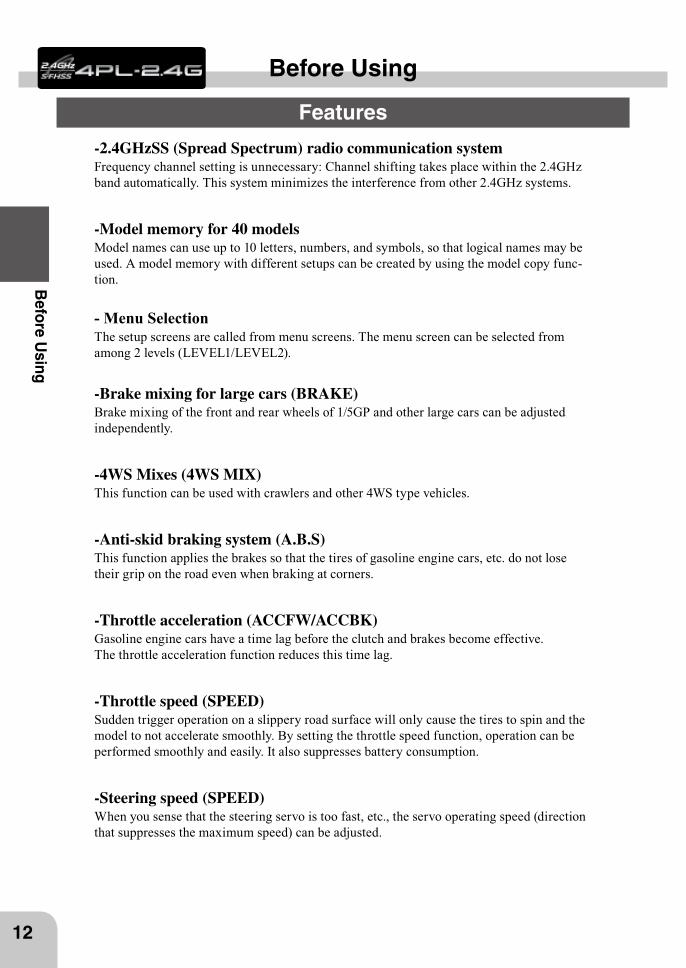
-2.4GHzSS (Spread Spectrum) radio communication systemFrequency channel setting is unnecessary: Channel shifting takes place within the 2.4GHz band automatically. This system minimizes the interference from other 2.4GHz systems.
-Model memory for 40 modelsModel names can use up to 10 letters, numbers, and symbols, so that logical names may be used. A model memory with different setups can be created by using the model copy func-tion.
- Menu SelectionThe setup screens are called from menu screens. The menu screen can be selected from among 2 levels (LEVEL1/LEVEL2).
-Brake mixing for large cars (BRAKE)Brake mixing of the front and rear wheels of 1/5GP and other large cars can be adjusted independently.
-4WS Mixes (4WS MIX)This function can be used with crawlers and other 4WS type vehicles.
-Anti-skid braking system (A.B.S)This function applies the brakes so that the tires of gasoline engine cars, etc. do not lose their grip on the road even when braking at corners.
-Throttle acceleration (ACCFW/ACCBK)Gasoline engine cars have a time lag before the clutch and brakes become effective. The throttle acceleration function reduces this time lag.
-Throttle speed (SPEED)Sudden trigger operation on a slippery road surface will only cause the tires to spin and the model to not accelerate smoothly. By setting the throttle speed function, operation can be performed smoothly and easily. It also suppresses battery consumption.
-Steering speed (SPEED)When you sense that the steering servo is too fast, etc., the servo operating speed (direction that suppresses the maximum speed) can be adjusted.
Before Using
Features
13
Bef
ore
Usi
ng
-Racing timer (TIMER)The lap timer can record 100 lap times and total time. The timer can also be started auto-matically by trigger operation. The race time and audible alarm can be set.Re-/fueling time are indicated by an audible alarm. An up timer is also provided.
-Digital trimThe current trim position is displayed on the LCD screen. The operating amount of 1 step can also be adjusted.Trim operation has no effect on the maximum travel of the steering and throttle servos.
-Function select trim/ dial function (TRIM DIAL)This function assigns functions to dials (digital trim, digital dial). The step amount and operating direction can also be adjusted. Trim positioning at each model call is unnecessary because all the dials are digital.
-Function select switch function (SWTCH)This function assigns functions to 2 switches. The operating direction can also be set.
-ESC-Link function (MC-LINK)This is a dedicated function which allows setting of the contents of the Link software which makes possible Futaba speed controller (ESC), MC950CR, MC850C, MC851C, MC602C, MC402CR, etc. variable frequency and other data changes by T4PL.
-Trigger position can be changedThe position of the throttle trigger can be moved forward and backward.
-Tension adjustment functionThe tension of the steering wheel & throttle trigger springs can be adjusted from the outside.
-Mechanical ATL AdjustmentMake this adjustment when you want to decrease the total travel of the brake (push) side of the throttle trigger.
-Display switchDisplay switch allows function setup without transmitting.
14
Before U
sing
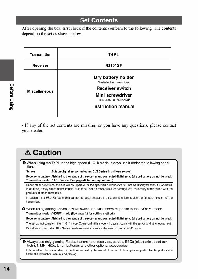
After opening the box, first check if the contents conform to the following. The contents depend on the set as shown below.
Set Contents
Transmitter T4PL
Receiver R2104GF
Miscellaneous
Dry battery holder*Installed in transmitter.
Receiver switchMini screwdriver* It is used for R2104GF.
Instruction manual
- If any of the set contents are missing, or you have any questions, please contact your dealer.
Caution When using the T4PL in the high speed (HIGH) mode, always use it under the following condi-tions:
Servos :Futaba digital servo (including BLS Series brushless servos)
Receiver’s battery :Matched to the ratings of the receiver and connected digital servo (dry cell battery cannot be used).Transmitter mode :"HIGH" mode (See page 42 for setting method.)
Under other conditions, the set will not operate, or the specified performance will not be displayed even if it operates. In addition, it may cause servo trouble. Futaba will not be responsible for damage, etc. caused by combination with the products of other companies.
In addition, the FSU Fail Safe Unit cannot be used because the system is different. Use the fail safe function of the transmitter.
When using analog servos, always switch the T4PL servo response to the "NORM" mode.Transmitter mode :"NORM" mode (See page 42 for setting method.)
Receiver’s battery :Matched to the ratings of the receiver and connected digital servo (dry cell battery cannot be used).
The set cannot operate in the "HIGH" mode. Operation in this mode will cause trouble with the servos and other equipment.
Digital servos (including BLS Series brushless servos) can also be used in the "NORM" mode.
Always use only genuine Futaba transmitters, receivers, servos, ESCs (electronic speed con-trols), NiMH, NiCd, Li-ion batteries and other optional accessories.
Futaba will not be responsible for problems caused by the use of other than Futaba genuine parts. Use the parts speci-fied in the instruction manual and catalog.
15
Bef
ore
Usi
ng
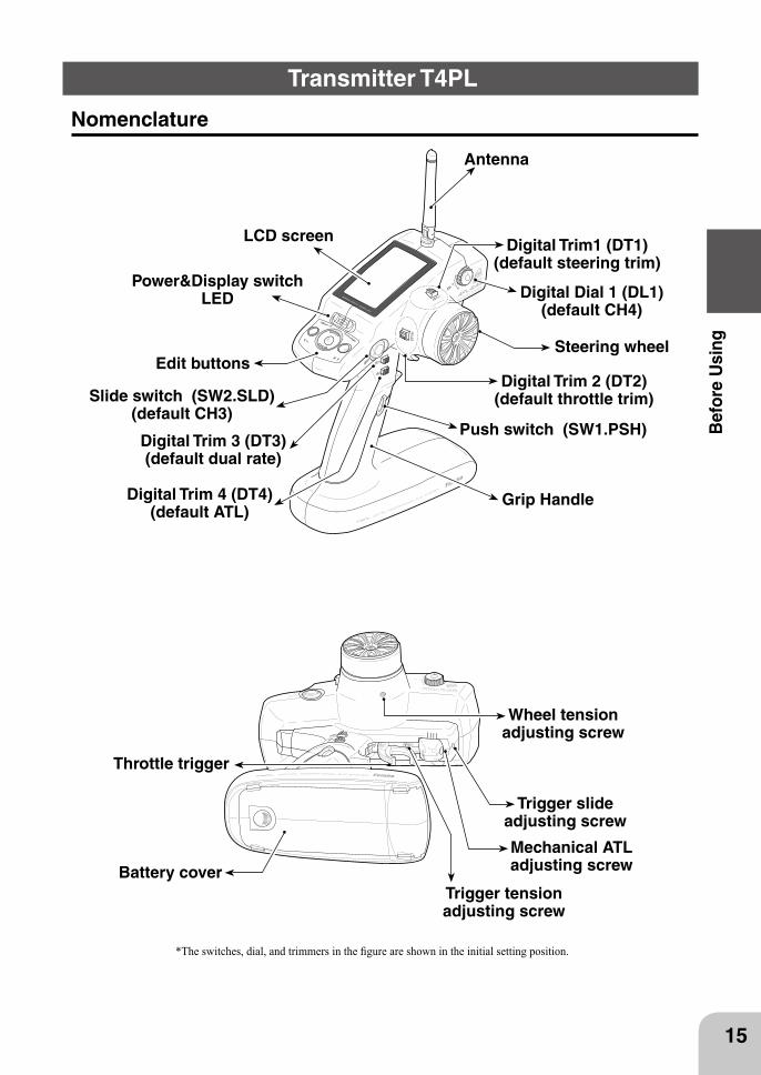
*The switches, dial, and trimmers in the figure are shown in the initial setting position.
Antenna
Digital Dial 1 (DL1)(default CH4)
Mechanical ATLadjusting screw
Throttle trigger
Power&Display switch LED
Digital Trim 2 (DT2)(default throttle trim)
Digital Trim 4 (DT4)(default ATL)
Digital Trim 3 (DT3)(default dual rate)
Grip Handle
Digital Trim1 (DT1)(default steering trim)
Steering wheel
Push switch (SW1.PSH)
Slide switch (SW2.SLD)(default CH3)
LCD screen
Edit buttons
Nomenclature
Transmitter T4PL
Wheel tensionadjusting screw
Trigger tensionadjusting screw
Battery cover
Trigger slide adjusting screw
Battery cover
Slide battery cover while pressing here.
16
Before U
sing
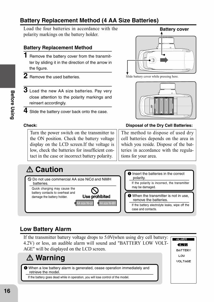
Battery Replacement Method
1 Remove the battery cover from the transmit-
ter by sliding it in the direction of the arrow in the figure.
2 Remove the used batteries.
3 Load the new AA size batteries. Pay very
close attention to the polarity markings and reinsert accordingly.
4 Slide the battery cover back onto the case.
Battery Replacement Method (4 AA Size Batteries)Load the four batteries in accordance with the polarity markings on the battery holder.
Check: Disposal of the Dry Cell Batteries:
Turn the power switch on the transmitter to the ON position. Check the battery voltage display on the LCD screen.If the voltage is low, check the batteries for insufficient con-tact in the case or incorrect battery polarity.
The method to dispose of used dry cell batteries depends on the area in which you reside. Dispose of the bat-teries in accordance with the regula-tions for your area.
Caution Do not use commercial AA size NiCd and NiMH batteries.
Quick charging may cause the battery contacts to overheat and damage the battery holder.
Insert the batteries in the correct polarity.
If the polarity is incorrect, the transmitter may be damaged.
When the transmitter is not in use, remove the batteries.
If the battery electrolyte leaks, wipe off the case and contacts.
Low Battery AlarmIf the transmitter battery voltage drops to 5.0V(when using dry cell battery: 4.2V) or less, an audible alarm will sound and "BATTERY LOW VOLT-AGE" will be displayed on the LCD screen.
WarningWhen a low battery alarm is generated, cease operation immediately and retrieve the model.
If the battery goes dead while in operation, you will lose control of the model.
AC outlet
Charger
Transmitter charging LED
To transmitter charging jack
To receiver Ni-Cd battery
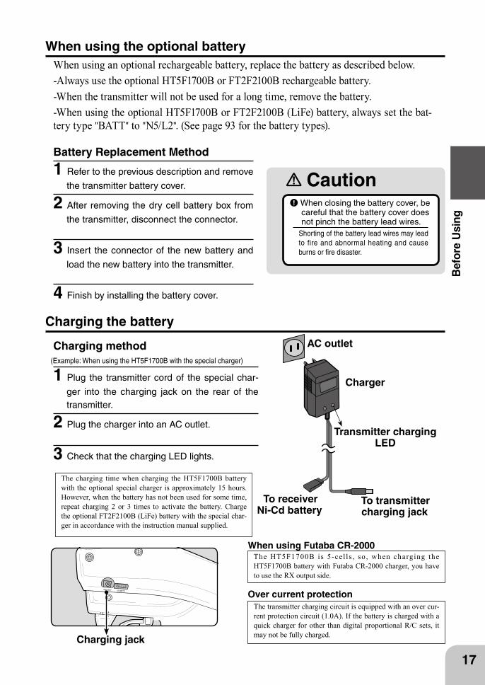
CautionWhen closing the battery cover, be careful that the battery cover does not pinch the battery lead wires.
Shorting of the battery lead wires may lead to fire and abnormal heating and cause burns or fire disaster.
17
Bef
ore
Usi
ng
Battery Replacement Method
1 Refer to the previous description and remove
the transmitter battery cover.
2 After removing the dry cell battery box from
the transmitter, disconnect the connector.
3 Insert the connector of the new battery and
load the new battery into the transmitter.
4 Finish by installing the battery cover.
When using the optional batteryWhen using an optional rechargeable battery, replace the battery as described below.-Always use the optional HT5F1700B or FT2F2100B rechargeable battery.-When the transmitter will not be used for a long time, remove the battery.-When using the optional HT5F1700B or FT2F2100B (LiFe) battery, always set the bat-tery type "BATT" to "N5/L2". (See page 93 for the battery types).
Over current protection
Charging jack
The transmitter charging circuit is equipped with an over cur-rent protection circuit (1.0A). If the battery is charged with a quick charger for other than digital proportional R/C sets, it may not be fully charged.
The charging time when charging the HT5F1700B battery with the optional special charger is approximately 15 hours. However, when the battery has not been used for some time, repeat charging 2 or 3 times to activate the battery. Charge the optional FT2F2100B (LiFe) battery with the special char-ger in accordance with the instruction manual supplied.
Charging method(Example: When using the HT5F1700B with the special charger)
1 Plug the transmitter cord of the special char-
ger into the charging jack on the rear of the transmitter.
2 Plug the charger into an AC outlet.
3 Check that the charging LED lights.
Charging the battery
The HT5F1700B is 5-cel ls , so , when charging the HT5F1700B battery with Futaba CR-2000 charger, you have to use the RX output side.
When using Futaba CR-2000
Warning
Caution
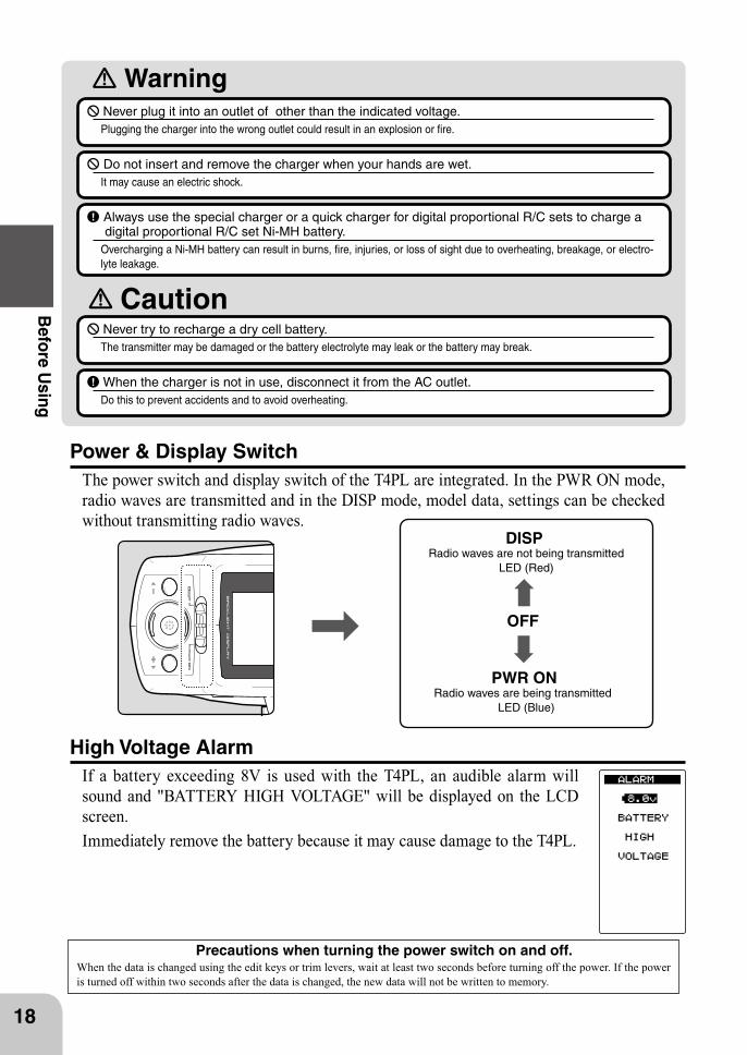
OFF
DISPRadio waves are not being transmitted
LED (Red)
PWR ONRadio waves are being transmitted
LED (Blue)
18
Before U
sing
Never plug it into an outlet of other than the indicated voltage.Plugging the charger into the wrong outlet could result in an explosion or fire.
Do not insert and remove the charger when your hands are wet.It may cause an electric shock.
Always use the special charger or a quick charger for digital proportional R/C sets to charge a digital proportional R/C set Ni-MH battery.
Overcharging a Ni-MH battery can result in burns, fire, injuries, or loss of sight due to overheating, breakage, or electro-lyte leakage.
Never try to recharge a dry cell battery.The transmitter may be damaged or the battery electrolyte may leak or the battery may break.
When the charger is not in use, disconnect it from the AC outlet.Do this to prevent accidents and to avoid overheating.
Power & Display SwitchThe power switch and display switch of the T4PL are integrated. In the PWR ON mode, radio waves are transmitted and in the DISP mode, model data, settings can be checked without transmitting radio waves.
High Voltage AlarmIf a battery exceeding 8V is used with the T4PL, an audible alarm will sound and "BATTERY HIGH VOLTAGE" will be displayed on the LCD screen.Immediately remove the battery because it may cause damage to the T4PL.
Precautions when turning the power switch on and off.When the data is changed using the edit keys or trim levers, wait at least two seconds before turning off the power. If the power is turned off within two seconds after the data is changed, the new data will not be written to memory.
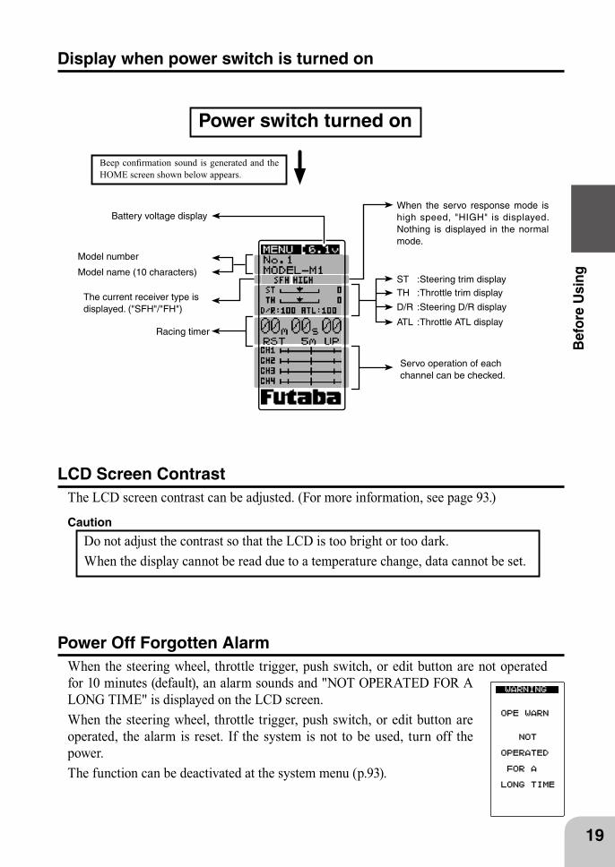
Battery voltage display
ST :Steering trim displayTH :Throttle trim display
D/R :Steering D/R display
ATL :Throttle ATL display
Power switch turned on
Beep confirmation sound is generated and the HOME screen shown below appears.
Display when power switch is turned on
Model name (10 characters)
The current receiver type is displayed. ("SFH"/"FH")
When the servo response mode is high speed, "HIGH" is displayed. Nothing is displayed in the normal mode.
Servo operation of each channel can be checked.
Model number
Racing timer
19
Bef
ore
Usi
ng
LCD Screen Contrast The LCD screen contrast can be adjusted. (For more information, see page 93.)
Caution
Do not adjust the contrast so that the LCD is too bright or too dark.When the display cannot be read due to a temperature change, data cannot be set.
Power Off Forgotten AlarmWhen the steering wheel, throttle trigger, push switch, or edit button are not operated for 10 minutes (default), an alarm sounds and "NOT OPERATED FOR A LONG TIME" is displayed on the LCD screen.When the steering wheel, throttle trigger, push switch, or edit button are operated, the alarm is reset. If the system is not to be used, turn off the power.The function can be deactivated at the system menu (p.93).
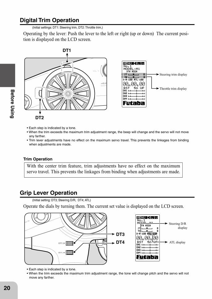
DT3
DT4 ATL display
Steering D/R display
DT2
DT1
Steering trim display
Throttle trim display
20
Before U
sing
Trim Operation
Digital Trim Operation (Initial settings: DT1: Steering trim, DT2: Throttle trim,)
Operating by the lever: Push the lever to the left or right (up or down) The current posi-tion is displayed on the LCD screen.
any farther.
when adjustments are made.
Grip Lever Operation (Initial setting: DT3; Steering D/R, DT4; ATL)
Operate the dials by turning them. The current set value is displayed on the LCD screen.
move any farther.
With the center trim feature, trim adjustments have no effect on the maximum servo travel. This prevents the linkages from binding when adjustments are made.
Mechanical ATL adjusting screw
21
Bef
ore
Usi
ng
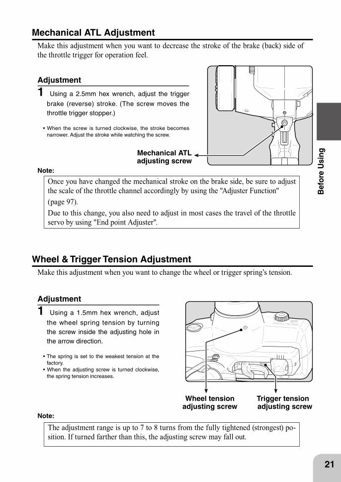
Adjustment
1 Using a 2.5mm hex wrench, adjust the trigger
brake (reverse) stroke. (The screw moves the throttle trigger stopper.)
narrower. Adjust the stroke while watching the screw.
Note:
Mechanical ATL AdjustmentMake this adjustment when you want to decrease the stroke of the brake (back) side of the throttle trigger for operation feel.
Wheel & Trigger Tension AdjustmentMake this adjustment when you want to change the wheel or trigger spring’s tension.
Adjustment
1 Using a 1.5mm hex wrench, adjust
the wheel spring tension by turning the screw inside the adjusting hole in the arrow direction.
factory.
the spring tension increases.
Note:
Wheel tensionadjusting screw
Once you have changed the mechanical stroke on the brake side, be sure to adjust the scale of the throttle channel accordingly by using the "Adjuster Function" (page 97). Due to this change, you also need to adjust in most cases the travel of the throttle servo by using "End point Adjuster".
The adjustment range is up to 7 to 8 turns from the fully tightened (strongest) po-sition. If turned farther than this, the adjusting screw may fall out.
Trigger tension adjusting screw
22
Before U
sing
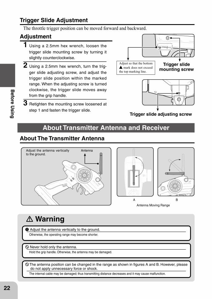
Trigger Slide AdjustmentThe throttle trigger position can be moved forward and backward.
Adjustment
1 Using a 2.5mm hex wrench, loosen the
trigger slide mounting screw by turning it slightly counterclockwise.
2 Using a 2.5mm hex wrench, turn the trig-
ger slide adjusting screw, and adjust the trigger slide position within the marked range. When the adjusting screw is turned clockwise, the trigger slide moves away from the grip handle.
3 Retighten the mounting screw loosened at
step 1 and fasten the trigger slide.Trigger slide adjusting screw
Adjust so that the bottom mark does not exceed
the top marking line.
Trigger slide mounting screw
Warning
Antenna Moving Range
Adjust the antenna vertically to the ground.
Antenna
A B
About The Transmitter Antenna
Adjust the antenna vertically to the ground.Otherwise, the operating range may become shorter.
The antenna position can be changed in the range as shown in figures A and B. However, please do not apply unnecessary force or shock.
The internal cable may be damaged; thus transmitting distance decreases and it may cause malfunction.
Never hold only the antenna.Hold the grip handle. Otherwise, the antenna may be damaged.
About Transmitter Antenna and Receiver
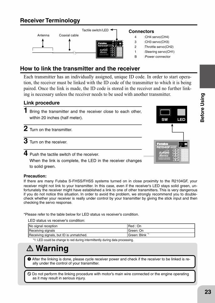
Antenna Coaxial cable
Tactile switch/LED
WarningAfter the linking is done, please cycle receiver power and check if the receiver to be linked is re-ally under the control of your transmitter.
Do not perform the linking procedure with motor’s main wire connected or the engine operating as it may result in serious injury.
23
Bef
ore
Usi
ng
Receiver Terminology
How to link the transmitter and the receiverEach transmitter has an individually assigned, unique ID code. In order to start opera-tion, the receiver must be linked with the ID code of the transmitter to which it is being paired. Once the link is made, the ID code is stored in the receiver and no further link-ing is necessary unless the receiver needs to be used with another transmitter.
Link procedure
1 Bring the transmitter and the receiver close to each other,
within 20 inches (half meter).
2 Turn on the transmitter.
3 Turn on the receiver.
4 Push the tactile switch of the receiver.
When the link is complete, the LED in the receiver changes to solid green.
Connectors4 :CH4 servo(CH4)
3 :CH3 servo(CH3)
2 :Throttle servo(CH2)
1 :Steering servo(CH1)
B :Power connector
No signal reception Red : OnReceiving signals Green: OnReceiving signals, but ID is unmatched. Green: Blink *1
LED status vs receiver's condition:
*1: LED could be change to red during intermittently during data processing.
Precaution: If there are many Futaba S-FHSS/FHSS systems turned on in close proximity to the R2104GF, your
receiver might not link to your transmitter. In this case, even if the receiver's LED stays solid green, un-fortunately the receiver might have established a link to one of other transmitters. This is very dangerous if you do not notice this situation. In order to avoid the problem, we strongly recommend you to double-check whether your receiver is really under control by your transmitter by giving the stick input and then checking the servo response.
*Please refer to the table below for LED status vs receiver's condition.
WARNING
Caution
Antennatube
Antenna
Coaxialcable
R2104GF
24
Before U
sing
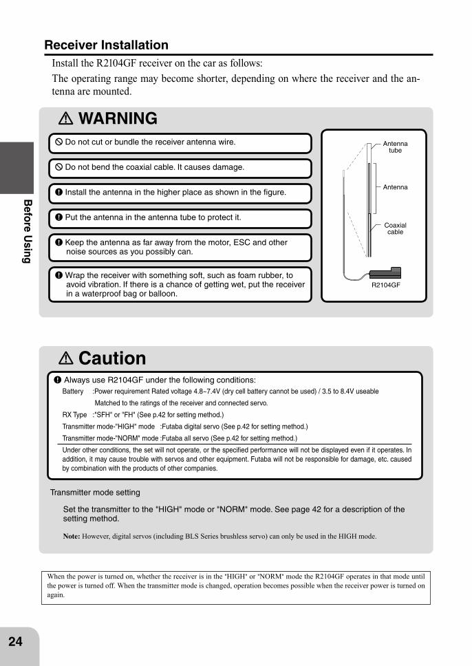
Always use R2104GF under the following conditions:Battery :Power requirement Rated voltage 4.8~7.4V (dry cell battery cannot be used) / 3.5 to 8.4V useable
Matched to the ratings of the receiver and connected servo.
RX Type :"SFH" or "FH" (See p.42 for setting method.)
Transmitter mode-"HIGH" mode :Futaba digital servo (See p.42 for setting method.)
Transmitter mode-"NORM" mode :Futaba all servo (See p.42 for setting method.)
Under other conditions, the set will not operate, or the specified performance will not be displayed even if it operates. In addition, it may cause trouble with servos and other equipment. Futaba will not be responsible for damage, etc. caused by combination with the products of other companies.
Receiver InstallationInstall the R2104GF receiver on the car as follows:The operating range may become shorter, depending on where the receiver and the an-tenna are mounted.
Do not cut or bundle the receiver antenna wire.
Do not bend the coaxial cable. It causes damage.
Install the antenna in the higher place as shown in the figure.
Put the antenna in the antenna tube to protect it.
Transmitter mode setting
Set the transmitter to the "HIGH" mode or "NORM" mode. See page 42 for a description of the setting method.
Note: However, digital servos (including BLS Series brushless servo) can only be used in the HIGH mode.
When the power is turned on, whether the receiver is in the "HIGH" or "NORM" mode the R2104GF operates in that mode until the power is turned off. When the transmitter mode is changed, operation becomes possible when the receiver power is turned on again.
Keep the antenna as far away from the motor, ESC and other noise sources as you possibly can.
Wrap the receiver with something soft, such as foam rubber, to avoid vibration. If there is a chance of getting wet, put the receiver in a waterproof bag or balloon.
B/C
CH3
CH2
CH1
CH4
Receiver
SwitchTo Battery
Steering servo
Throttle servo
CH3 servo
CH4 servo
25
Inst
alla
tion
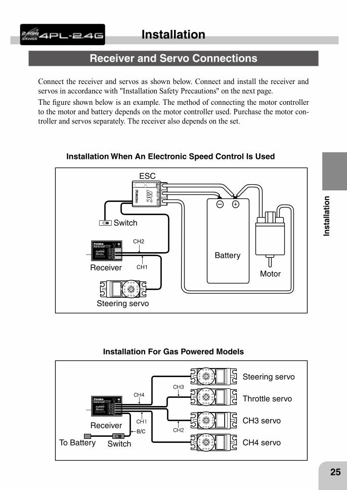
Connect the receiver and servos as shown below. Connect and install the receiver and servos in accordance with "Installation Safety Precautions" on the next page.The figure shown below is an example. The method of connecting the motor controller to the motor and battery depends on the motor controller used. Purchase the motor con-troller and servos separately. The receiver also depends on the set.
Installation When An Electronic Speed Control Is Used
Installation For Gas Powered Models
Installation
Receiver and Servo Connections
Installation Safety Precautions
Warning
26
Installation
Receiver (receiver antenna)
Receiver vibration-proofing / waterproofing
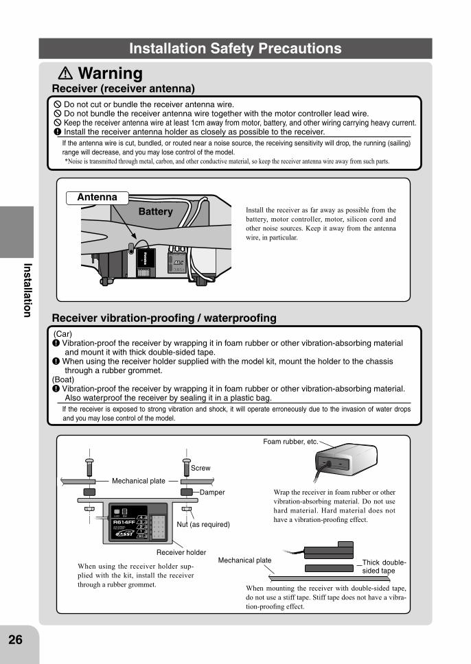
Do not cut or bundle the receiver antenna wire. Do not bundle the receiver antenna wire together with the motor controller lead wire. Keep the receiver antenna wire at least 1cm away from motor, battery, and other wiring carrying heavy current. Install the receiver antenna holder as closely as possible to the receiver.If the antenna wire is cut, bundled, or routed near a noise source, the receiving sensitivity will drop, the running (sailing) range will decrease, and you may lose control of the model.*Noise is transmitted through metal, carbon, and other conductive material, so keep the receiver antenna wire away from such parts.
(Car) Vibration-proof the receiver by wrapping it in foam rubber or other vibration-absorbing material
and mount it with thick double-sided tape.When using the receiver holder supplied with the model kit, mount the holder to the chassis through a rubber grommet.
(Boat) Vibration-proof the receiver by wrapping it in foam rubber or other vibration-absorbing material.
Also waterproof the receiver by sealing it in a plastic bag.If the receiver is exposed to strong vibration and shock, it will operate erroneously due to the invasion of water drops and you may lose control of the model.
Screw
Mechanical plate
Nut (as required)
Receiver holder
Damper
When using the receiver holder sup-plied with the kit, install the receiver through a rubber grommet.
Foam rubber, etc.
Wrap the receiver in foam rubber or other vibration-absorbing material. Do not use hard material. Hard material does not have a vibration-proofing effect.
Mechanical plate Thick double-sided tape
When mounting the receiver with double-sided tape, do not use a stiff tape. Stiff tape does not have a vibra-tion-proofing effect.
AntennaInstall the receiver as far away as possible from the battery, motor controller, motor, silicon cord and other noise sources. Keep it away from the antenna wire, in particular.
Battery
Warning
27
Inst
alla
tion
Connector Connections
Servo Installation
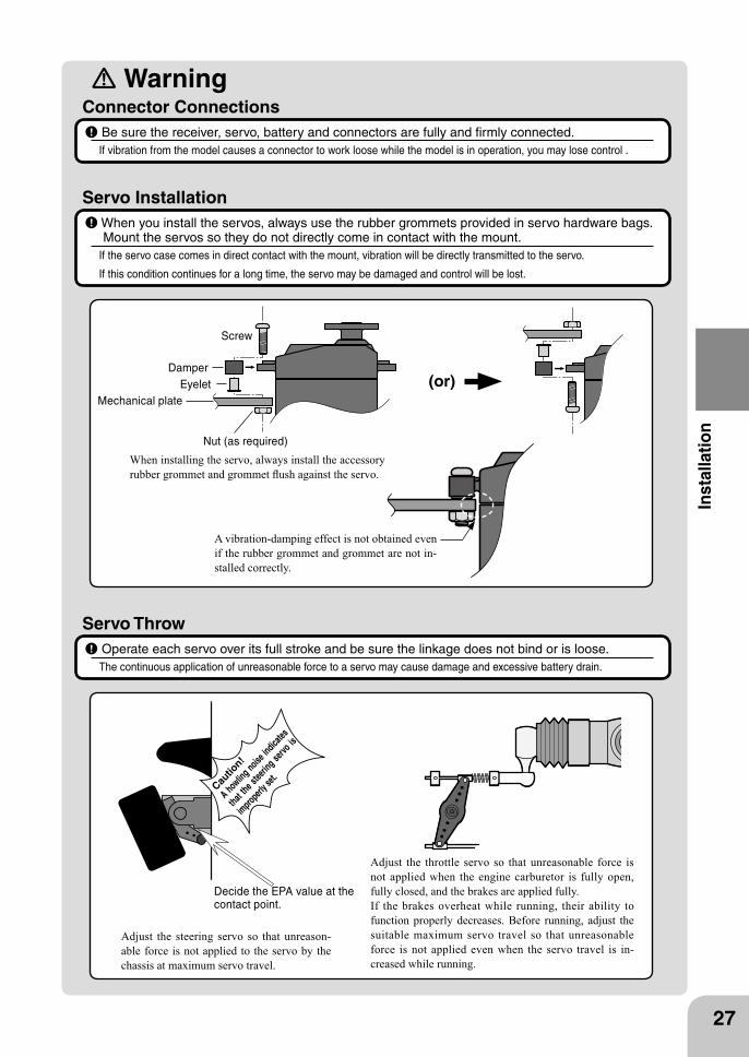
Be sure the receiver, servo, battery and connectors are fully and firmly connected.If vibration from the model causes a connector to work loose while the model is in operation, you may lose control .
When you install the servos, always use the rubber grommets provided in servo hardware bags. Mount the servos so they do not directly come in contact with the mount.
If the servo case comes in direct contact with the mount, vibration will be directly transmitted to the servo.
If this condition continues for a long time, the servo may be damaged and control will be lost.
Servo Throw Operate each servo over its full stroke and be sure the linkage does not bind or is loose.The continuous application of unreasonable force to a servo may cause damage and excessive battery drain.
Screw
Mechanical plate
Nut (as required)
EyeletDamper
(or)
When installing the servo, always install the accessory rubber grommet and grommet flush against the servo.
A vibration-damping effect is not obtained even if the rubber grommet and grommet are not in-stalled correctly.
Adjust the throttle servo so that unreasonable force is not applied when the engine carburetor is fully open, fully closed, and the brakes are applied fully.If the brakes overheat while running, their ability to function properly decreases. Before running, adjust the suitable maximum servo travel so that unreasonable force is not applied even when the servo travel is in-creased while running.
Adjust the steering servo so that unreason-able force is not applied to the servo by the chassis at maximum servo travel.
Decide the EPA value at the contact point.
Cautio
n!
A howlin
g noise in
dicates
that the s
teerin
g servo
is
improperl
y set.
Warning
28
Installation
Electronic Speed Control
Motor Noise Suppression
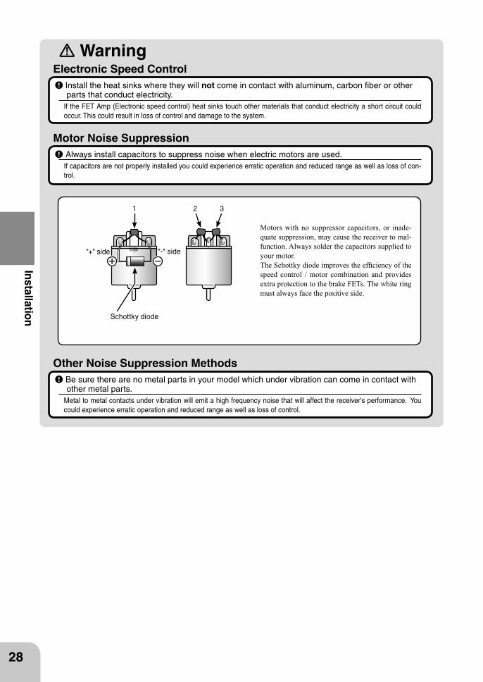
Install the heat sinks where they will not come in contact with aluminum, carbon fiber or other parts that conduct electricity.
If the FET Amp (Electronic speed control) heat sinks touch other materials that conduct electricity a short circuit could occur. This could result in loss of control and damage to the system.
Always install capacitors to suppress noise when electric motors are used.If capacitors are not properly installed you could experience erratic operation and reduced range as well as loss of con-trol.
Other Noise Suppression Methods Be sure there are no metal parts in your model which under vibration can come in contact with other metal parts.
Metal to metal contacts under vibration will emit a high frequency noise that will affect the receiver's performance. You could experience erratic operation and reduced range as well as loss of control.
Motors with no suppressor capacitors, or inade-quate suppression, may cause the receiver to mal-function. Always solder the capacitors supplied to your motor.The Schottky diode improves the efficiency of the speed control / motor combination and provides extra protection to the brake FETs. The white ring must always face the positive side.
Schottky diode
"-" side"+" side
1 2 3
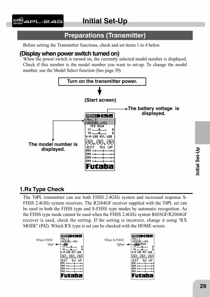
When FHSS When S-FHSS"FH" "SFH"
29
Initi
al S
et-U
p
Before setting the Transmitter functions, check and set items 1 to 4 below.
Initial Set-Up
Preparations (Transmitter)
(Display when power switch turned on)When the power switch is turned on, the currently selected model number is displayed. Check if this number is the model number you want to set-up. To change the model number, use the Model Select function (See page 39).
(Start screen)
Turn on the transmitter power.
The model number is displayed.
The battery voltage is displayed.
1.Rx Type CheckThe T4PL transmitter can use both FHSS 2.4GHz system and increased response S-FHSS 2.4GHz system receivers. The R2104GF receiver supplied with the T4PL set can be used in both the FHSS type and S-FHSS type modes by automatic recognition. As the FHSS type mode cannot be used when the FHSS 2.4GHz system R603GF/R2004GF receiver is used, check the setting. If the setting is incorrect, change it using "RX MODE" (P42). Which RX type is set can be checked with the HOME screen.
Throttle trim (DT2)Steering trim (DT1)
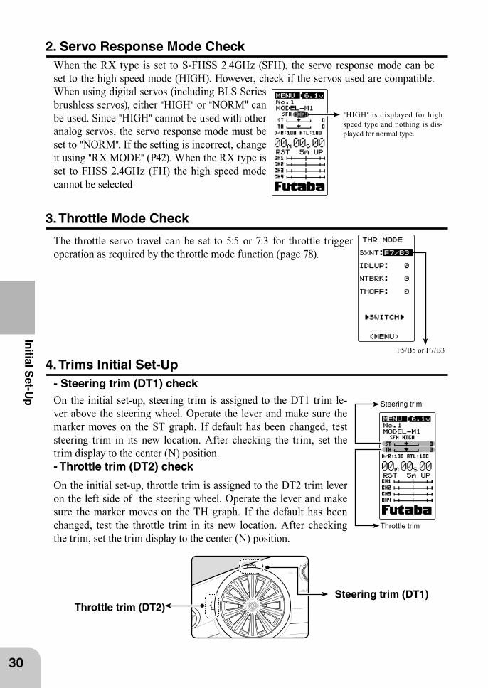
"HIGH" is displayed for high speed type and nothing is dis-played for normal type.
F5/B5 or F7/B3
Steering trim
Throttle trim
30
Initial Set-U
p
4. Trims Initial Set-Up - Steering trim (DT1) checkOn the initial set-up, steering trim is assigned to the DT1 trim le-ver above the steering wheel. Operate the lever and make sure the marker moves on the ST graph. If default has been changed, test steering trim in its new location. After checking the trim, set the trim display to the center (N) position. - Throttle trim (DT2) check
2. Servo Response Mode Check When the RX type is set to S-FHSS 2.4GHz (SFH), the servo response mode can be set to the high speed mode (HIGH). However, check if the servos used are compatible. When using digital servos (including BLS Series brushless servos), either "HIGH" or "NORM" can be used. Since "HIGH" cannot be used with other analog servos, the servo response mode must be set to "NORM". If the setting is incorrect, change it using "RX MODE" (P42). When the RX type is set to FHSS 2.4GHz (FH) the high speed mode cannot be selected
On the initial set-up, throttle trim is assigned to the DT2 trim lever on the left side of the steering wheel. Operate the lever and make sure the marker moves on the TH graph. If the default has been changed, test the throttle trim in its new location. After checking the trim, set the trim display to the center (N) position.
3. Throttle Mode Check
The throttle servo travel can be set to 5:5 or 7:3 for throttle trigger operation as required by the throttle mode function (page 78).
Throttle ATL
Steering dual rate
31
Initi
al S
et-U
p
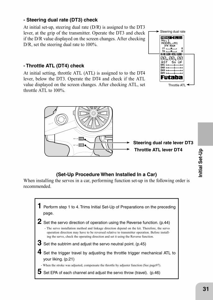
(Set-Up Procedure When Installed In a Car) When installing the servos in a car, performing function set-up in the following order is recommended.
1 Perform step 1 to 4. Trims Initial Set-Up of Preparations on the preceding
page.
2 Set the servo direction of operation using the Reverse function. (p.44) - The servo installation method and linkage direction depend on the kit. Therefore, the servo
operation direction may have to be reversed relative to transmitter operation. Before install-ing the servo, check the operating direction and set it using the Reverse function.
3 Set the subtrim and adjust the servo neutral point. (p.45)
4 Set the trigger travel by adjusting the throttle trigger mechanical ATL to
your liking. (p.21) - When the stroke was adjusted, compensate the throttle by adjuster function (See page97).
5 Set EPA of each channel and adjust the servo throw (travel). (p.46)
Steering dual rate lever DT3
Throttle ATL lever DT4
- Steering dual rate (DT3) check At initial set-up, steering dual rate (D/R) is assigned to the DT3 lever, at the grip of the transmitter. Operate the DT3 and check if the D/R value displayed on the screen changes. After checking D/R, set the steering dual rate to 100%.
- Throttle ATL (DT4) check At initial setting, throttle ATL (ATL) is assigned to to the DT4 lever, below the DT3. Operate the DT4 and check if the ATL value displayed on the screen changes. After checking ATL, set throttle ATL to 100%.
UPDN
UPDN
Item selection The items move in the order
shown in the figure above.
UP
DN CT
Edit Buttons
STEERING is selected on the menu screen.
CT
(MENU screen)
CT
(MODEL RX screen)
CT
(TIMER screen)
32
Function Map
Function Map
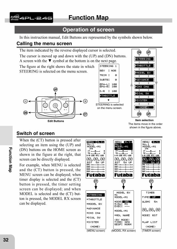
Operation of screenIn this instruction manual, Edit Buttons are represented by the symbols shown below.
Calling the menu screenThe item indicated by the reverse displayed cursor is selected.The cursor is moved up and down with the (UP) and (DN) buttons. A screen with the ▼ symbol at the bottom is on the next page.The figure at the right shows the state in which STEERING is selected on the menu screen.
Switch of screenWhen the (CT) button is pressed after selecting an item using the (UP) and (DN) buttons on the HOME screen as shown in the figure at the right, that screen can be directly displayed.For example, when MENU is selected and the (CT) button is pressed, the MENU screen can be displayed; when timer display is selected and the (CT) button is pressed, the timer setting screen can be displayed; and when MODEL is selected and the (CT) but-ton is pressed, the MODEL RX screen can be displayed.
STEERING selected by press-ing the (UP) or (DN) button on
the menu screen.
When cursor indicates a data setting item.
Pressed simultaneously.
Pressed simultaneously.
When an item with * is selected.
Data setting items with * are moved to another
item by pressing the (UP) or (DN) button.
THROTTLE selected by press-ing the (UP) or (DN) button on
the STEERING 1 screen.
CTCT
(STEERING 1 screen) (THROTTLE screen)
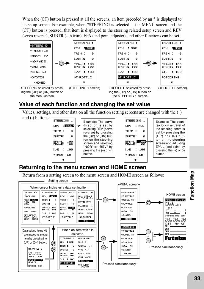
Example: The servo d irec t ion is set by selecting REV (servo reverse) by pressing the (UP) or (DN) but-ton on the steering screen and selecting "NOR" or "REV" by pressing the (+) or (-) button.
Example: The coun-terclockwise travel of the steering servo is set by pressing the ( UP) o r ( DN ) bu t -ton on the steering screen and adjusting EPA-L (end point) by pressing the (+) or (-) button.
CTCT
UP
DN
Setting screenMENU screen
HOME screen
33
Func
tion
Map
When the (CT) button is pressed at all the screens, an item preceded by an * is displayed to its setup screen. For example, when *STEERING is selected at the MENU screen and the (CT) button is pressed, that item is displayed to the steering related setup screen and REV (servo reverse), SUBTR (sub trim), EPA (end point adjuster), and other functions can be set.
Value of each function and changing the set valueValues, settings, and other data on all the function setting screens are changed with the (+) and (-) buttons.
Returning to the menu screen and HOME screenReturn from a setting screen to the menu screen and HOME screen as follows:
(MENU screen)(HOME screen)
(MODEL RX screen)
(TIMER screen)
(ADVANCE screen)
(SYSTEM screen)
34
Function Map
35
Func
tion
Map
Function abbreviation
Description of function PageNo
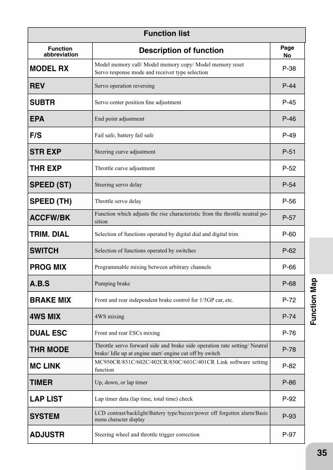
MODEL RXModel memory call/ Model memory copy/ Model memory resetServo response mode and receiver type selection P-38
REV Servo operation reversing P-44
SUBTR Servo center position fine adjustment P-45
EPA End point adjustment P-46
F/S Fail safe, battery fail safe P-49
STR EXP Steering curve adjustment P-51
THR EXP Throttle curve adjustment P-52
SPEED (ST) Steering servo delay P-54
SPEED (TH) Throttle servo delay P-56
ACCFW/BKFunction which adjusts the rise characteristic from the throttle neutral po-sition P-57
TRIM. DIAL Selection of functions operated by digital dial and digital trim P-60
SWITCH Selection of functions operated by switches P-62
PROG MIX Programmable mixing between arbitrary channels P-66
A.B.S Pumping brake P-68
BRAKE MIX Front and rear independent brake control for 1/5GP car, etc. P-72
4WS MIX 4WS mixing P-74
DUAL ESC Front and rear ESCs mixing P-76
THR MODEThrottle servo forward side and brake side operation rate setting/ Neutral brake/ Idle up at engine start/ engine cut off by switch P-78
MC LINKMC950CR/851C/602C/402CR/850C/601C/401CR Link software setting function P-82
TIMER Up, down, or lap timer P-86
LAP LIST Lap timer data (lap time, total time) check P-92
SYSTEM LCD contrast/backlight/Battery type/buzzer/power off forgotten alarm/Basic menu character display P-93
ADJUSTR Steering wheel and throttle trigger correction P-97
Function list
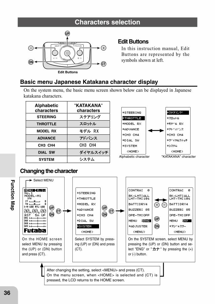
On the HOME screen select MENU by pressing the (UP) or (DN) button and press (CT).
Select SYSTEM by press-ing (UP) or (DN) and press (CT).
On the SYSTEM screen, select MENU by pressing the (UP) or (DN) button and se-lect "ENG" or " " by pressing the (+) or (-) button.
UP
DN CT
Edit Buttons
Alphabetic character "KATAKANA" character
Alphabeticcharacters
"KATAKANA"characters
STEERING
THROTTLE
MODEL RX
ADVANCE
CH3 CH4
DIAL SW
SYSTEM
CTDN
UP
DN
UP
CTDN
UP
Select MENU
36
Function Map
Characters selection
Edit ButtonsIn this instruction manual, Edit Buttons are represented by the symbols shown at left.
Basic menu Japanese Katakana character displayOn the system menu, the basic menu screen shown below can be displayed in Japanese katakana characters.
Changing the character
After changing the setting, select <MENU> and press (CT).On the menu screen, when <HOME> is selected and (CT) is pressed, the LCD returns to the HOME screen.
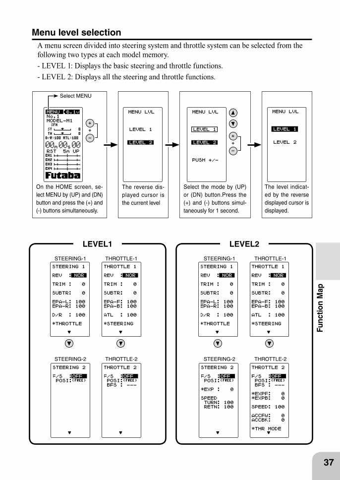
Select the mode by (UP) or (DN) button.Press the (+) and (-) buttons simul-taneously for 1 second.
On the HOME screen, se-lect MENU by (UP) and (DN) button and press the (+) and (-) buttons simultaneously.
The level indicat-ed by the reverse displayed cursor is displayed.
The reverse dis-played cursor is the current level
STEERING-1 STEERING-1 THROTTLE-1 THROTTLE-1
STEERING-2 STEERING-2 THROTTLE-2 THROTTLE-2
LEVEL1 LEVEL2
37
Func
tion
Map
Menu level selectionA menu screen divided into steering system and throttle system can be selected from the following two types at each model memory.- LEVEL 1: Displays the basic steering and throttle functions.- LEVEL 2: Displays all the steering and throttle functions.
Select MENU
CT
Select MODEL
(HOME screen) (MODEL RX screen)
Select MENU
(HOME screen) (MENU screen) (MODEL RX screen)
CTCT
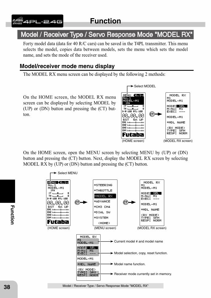
Receiver mode currently set in memory.
Model name function.
Model selection, copy, reset function.
Current model # and model name
38
Function
Function
Model / Receiver Type / Servo Response Mode "MODEL RX"
Model / Receiver Type / Servo Response Mode "MODEL RX"
Forty model data (data for 40 R/C cars) can be saved in the T4PL transmitter. This menu selects the model, copies data between models, sets the menu which sets the model name, and sets the mode of the receiver used.
Model/receiver mode menu displayThe MODEL RX menu screen can be displayed by the following 2 methods:
On the HOME screen, the MODEL RX menu screen can be displayed by selecting MODEL by (UP) or (DN) button and pressing the (CT) but-ton.
On the HOME screen, open the MENU screen by selecting MENU by (UP) or (DN) button and pressing the (CT) button. Next, display the MODEL RX screen by selecting MODEL RX by (UP) or (DN) button and pressing the (CT) button.
Move the cursor to EXEC:+/- and press the (+) and ( - ) buttons simultaneously for ap-proximately 1 second.
Modified model # and model name
Move the cursor to M-No and select model # with the (+) or (-) button.
Move the cursor to MODE and select "SEL" with the (+) or (-) button.
39
Function
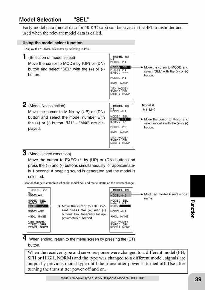
Model Selection "SEL"Forty model data (model data for 40 R/C cars) can be saved in the 4PL transmitter and used when the relevant model data is called.
Model / Receiver Type / Servo Response Mode "MODEL RX"
When the receiver type and servo response were changed to a different model (FH, SFH or HIGH, NORM) and the type was changed to a different model, signals are output by previous model type until the transmitter power is turned off. Use after turning the transmitter power off and on.
- Display the MODEL RX menu by referring to P38.
1 (Selection of model select)
Move the cursor to MODE by (UP) or (DN) button and select "SEL" with the (+) or (-) button.
Using the model select function
Model #. M1~M40
2 (Model No. selection)
Move the cursor to M-No by (UP) or (DN) button and select the model number with the (+) or (-) button. "M1" ~ "M40" are dis-played.
3 (Model select execution)
Move the cursor to EXEC:+/- by (UP) or (DN) button and press the (+) and (-) buttons simultaneously for approximate-ly 1 second. A beeping sound is generated and the model is selected.
- Model change is complete when the model No. and model name on the screen change.
4 When ending, return to the menu screen by pressing the (CT)
button.
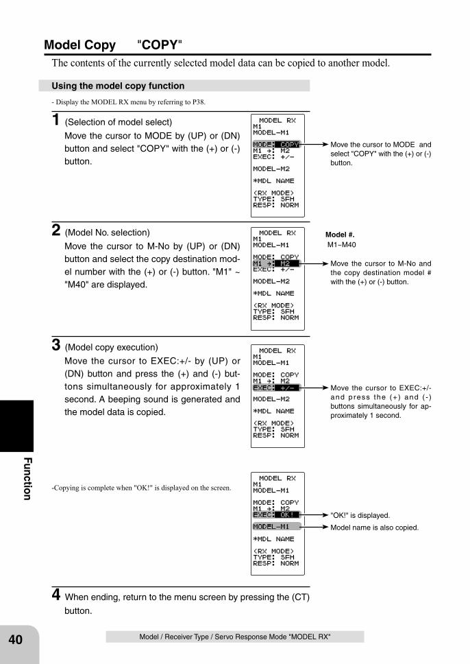
Move the cursor to MODE and select "COPY" with the (+) or (-) button.
Move the cursor to M-No and the copy destination model # with the (+) or (-) button.
Model #. M1~M40
Move the cursor to EXEC:+/- and press the (+) and ( - ) buttons simultaneously for ap-proximately 1 second.
"OK!" is displayed.
Model name is also copied.
40
Function
Model / Receiver Type / Servo Response Mode "MODEL RX"
Model Copy "COPY"The contents of the currently selected model data can be copied to another model.
- Display the MODEL RX menu by referring to P38.
1 (Selection of model select)
Move the cursor to MODE by (UP) or (DN) button and select "COPY" with the (+) or (-) button.
Using the model copy function
2 (Model No. selection)
Move the cursor to M-No by (UP) or (DN) button and select the copy destination mod-el number with the (+) or (-) button. "M1" ~ "M40" are displayed.
3 (Model copy execution)
Move the cursor to EXEC:+/- by (UP) or (DN) button and press the (+) and (-) but-tons simultaneously for approximately 1 second. A beeping sound is generated and the model data is copied.
-Copying is complete when "OK!" is displayed on the screen.
4 When ending, return to the menu screen by pressing the (CT)
button.
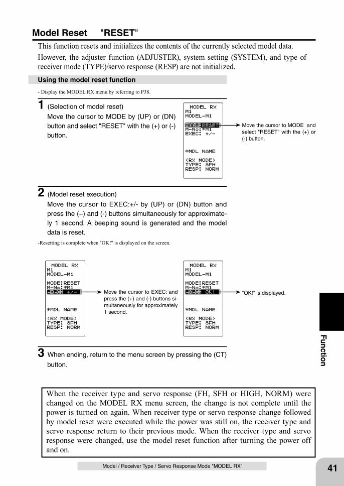
Move the cursor to EXEC: and press the (+) and (-) buttons si-multaneously for approximately 1 second.
"OK!" is displayed.
Move the cursor to MODE and select "RESET" with the (+) or (-) button.
41
Function
Model / Receiver Type / Servo Response Mode "MODEL RX"
Using the model reset function
Model Reset "RESET"This function resets and initializes the contents of the currently selected model data.However, the adjuster function (ADJUSTER), system setting (SYSTEM), and type of receiver mode (TYPE)/servo response (RESP) are not initialized.
- Display the MODEL RX menu by referring to P38.
1 (Selection of model reset)
Move the cursor to MODE by (UP) or (DN) button and select "RESET" with the (+) or (-) button.
When the receiver type and servo response (FH, SFH or HIGH, NORM) were changed on the MODEL RX menu screen, the change is not complete until the power is turned on again. When receiver type or servo response change followed by model reset were executed while the power was still on, the receiver type and servo response return to their previous mode. When the receiver type and servo response were changed, use the model reset function after turning the power off and on.
2 (Model reset execution)
Move the cursor to EXEC:+/- by (UP) or (DN) button and press the (+) and (-) buttons simultaneously for approximate-ly 1 second. A beeping sound is generated and the model data is reset.
-Resetting is complete when "OK!" is displayed on the screen.
3 When ending, return to the menu screen by pressing the (CT)
button.
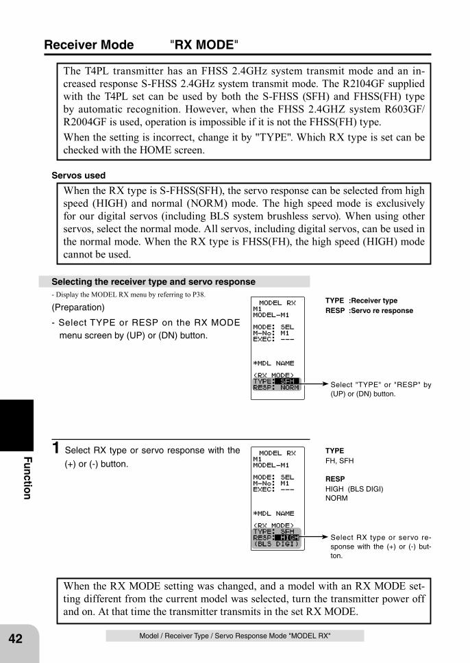
Select "TYPE" or "RESP" by (UP) or (DN) button.
Select RX type or servo re-sponse with the (+) or (-) but-ton.
TYPEFH, SFH
RESP HIGH (BLS DIGI)NORM
TYPE :Receiver typeRESP :Servo re response
42
Function
Model / Receiver Type / Servo Response Mode "MODEL RX"
Receiver Mode "RX MODE"
The T4PL transmitter has an FHSS 2.4GHz system transmit mode and an in-creased response S-FHSS 2.4GHz system transmit mode. The R2104GF supplied with the T4PL set can be used by both the S-FHSS (SFH) and FHSS(FH) type by automatic recognition. However, when the FHSS 2.4GHZ system R603GF/R2004GF is used, operation is impossible if it is not the FHSS(FH) type.When the setting is incorrect, change it by "TYPE". Which RX type is set can be checked with the HOME screen.
When the RX type is S-FHSS(SFH), the servo response can be selected from high speed (HIGH) and normal (NORM) mode. The high speed mode is exclusively for our digital servos (including BLS system brushless servo). When using other servos, select the normal mode. All servos, including digital servos, can be used in the normal mode. When the RX type is FHSS(FH), the high speed (HIGH) mode cannot be used.
Servos used
Selecting the receiver type and servo response- Display the MODEL RX menu by referring to P38.
(Preparation)
- Select TYPE or RESP on the RX MODE menu screen by (UP) or (DN) button.
When the RX MODE setting was changed, and a model with an RX MODE set-ting different from the current model was selected, turn the transmitter power off and on. At that time the transmitter transmits in the set RX MODE.
1 Select RX type or servo response with the
(+) or (-) button.
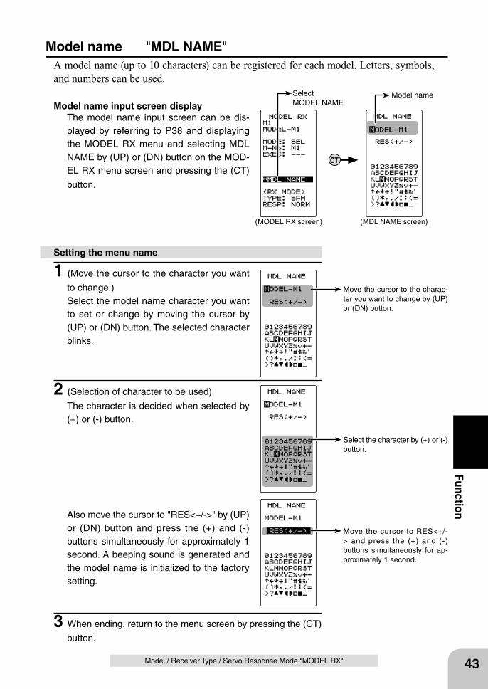
Move the cursor to the charac-ter you want to change by (UP) or (DN) button.
Select the character by (+) or (-) button.
CT
Select MODEL NAME
Model name
(MODEL RX screen) (MDL NAME screen)
Move the cursor to RES<+/-> and press the (+) and (-) buttons simultaneously for ap-proximately 1 second.
43
Function
Model / Receiver Type / Servo Response Mode "MODEL RX"
Setting the menu name
Model name "MDL NAME"A model name (up to 10 characters) can be registered for each model. Letters, symbols, and numbers can be used.
Model name input screen displayThe model name input screen can be dis-played by referring to P38 and displaying the MODEL RX menu and selecting MDL NAME by (UP) or (DN) button on the MOD-EL RX menu screen and pressing the (CT)
button.
1 (Move the cursor to the character you want
to change.)Select the model name character you want to set or change by moving the cursor by (UP) or (DN) button. The selected character blinks.
2 (Selection of character to be used)
The character is decided when selected by (+) or (-) button.
Also move the cursor to "RES<+/->" by (UP) or (DN) button and press the (+) and (-) buttons simultaneously for approximately 1 second. A beeping sound is generated and the model name is initialized to the factory setting.
3 When ending, return to the menu screen by pressing the (CT)
button.
Select MENU
(HOME screen) (MENU screen)
DNUP
Move the cursor to *STEERING by (UP) or (DN) button and press the (CT) button.
Move the cursor to *THROTTLE by (UP) or (DN) button and press the (CT) button.
Channel menu screens
(STEERING 1 menu screen) (THROTTLE 1 menu screen) (CH3/CH4 menu screen)
CT
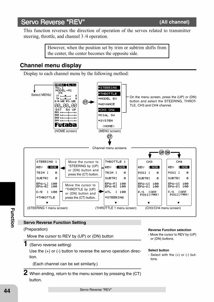
On the menu screen, press the (UP) or (DN) button and select the STEERING, THROT-TLE, CH3 and CH4 channel.
44
Function
Servo Reverse "REV"
However, when the position set by trim or subtrim shifts from the center, the center becomes the opposite side.
Servo Reverse "REV" (All channel)
This function reverses the direction of operation of the servos related to transmitter steering, throttle, and channel 3 /4 operation.
(Preparation)
Move the cursor to REV by (UP) or (DN) button
1 (Servo reverse setting)
Use the (+) or (-) button to reverse the servo operation direc-tion.
(Each channel can be set similarly.)
2 When ending, return to the menu screen by pressing the (CT)
button.
Servo Reverse Function Setting
Select button- Select with the (+) or (-) but-
tons.
Reverse Function selection- Move the cursor to REV by (UP)
or (DN) buttons.
CT
Channel menu displayDisplay to each channel menu by the following method:
DNUP
Move the cursor to *STEERING by (UP) or (DN) button and press the (CT) button.
Move the cursor to *THROTTLE by (UP) or (DN) button and press the (CT) button.
Channel menu screens
(STEERING 1 menu screen) (THROTTLE 1 menu screen) (CH3/CH4 menu screen)
90deg
Use to adjust the neutral position
45
Function
Subtrim "SUBTR"
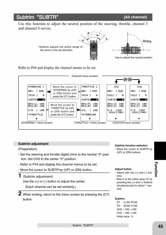
Use this function to adjust the neutral position of the steering, throttle, channel 3 and channel 4 servos.
(Preparation)
- Set the steering and throttle digital trims to the neutral "0" posi-tion. Set CH3 to the center "0" position.
- Refer to P44 and display the channel menus to be set.
- Move the cursor to SUBTR by (UP) or (DN) button.
1 (Subtrim adjustment)
Use the (+) or (-) button to adjust the center.
(Each channel can be set similarly.)
2 When ending, return to the menu screen by pressing the (CT)
button.
Subtrim adjustment
*Subtrim adjusts the entire range of the servo in the set direction.
Subtrim "SUBTR" (All channel)
Adjust button- Adjust with the (+) and (-) but-
tons.- Return to the initial value "0" by
pressing the (+) and (-) buttons simultaneously for about 1 sec-ond.
Subtrim function selection- Move the cursor to SUBTR by
(UP) or (DN) buttons.
Subtrim ST :L100~R100 TH :B100~F100 CH3 :-100~+100 CH4 :-100~+100 Initial value : 0
Refer to P44 and display the channel menus to be set.
46
Function
Warning
End Point Adjuster "EPA" (All channel)
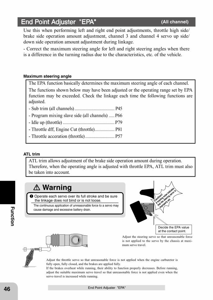
Use this when performing left and right end point adjustments, throttle high side/brake side operation amount adjustment, channel 3 and channel 4 servo up side/down side operation amount adjustment during linkage.- Correct the maximum steering angle for left and right steering angles when there is a difference in the turning radius due to the characteristics, etc. of the vehicle.
The EPA function basically determines the maximum steering angle of each channel. The functions shown below may have been adjusted or the operating range set by EPA function may be exceeded. Check the linkage each time the following functions are adjusted.- Sub trim (all channels) .................................. P45- Program mixing slave side (all channels) .....P66- Idle up (throttle) ............................................P79- Throttle dff, Engine Cut (throttle)................. P81- Throttle acceration (throttle) ......................... P57
Maximum steering angle
ATL trim allows adjustment of the brake side operation amount during operation. Therefore, when the operating angle is adjusted with throttle EPA, ATL trim must also be taken into account.
ATL trim
End Point Adjuster "EPA"
Operate each servo over its full stroke and be sure the linkage does not bind or is not loose.
The continuous application of unreasonable force to a servo may cause damage and excessive battery drain.
Adjust the throttle servo so that unreasonable force is not applied when the engine carburetor is fully open, fully closed, and the brakes are applied fully.If the brakes overheat while running, their ability to function properly decreases. Before running, adjust the suitable maximum servo travel so that unreasonable force is not applied even when the servo travel is increased while running.
Adjust the steering servo so that unreasonable force is not applied to the servo by the chassis at maxi-mum servo travel.
Caution!
A howling noise indicates
that the steerin
g servo is
improperly set.
Decide the EPA value at the contact point.
(STEERING 1 menu screen) (THROTTLE 1 menu screen) (CH3/CH4 menu screen)
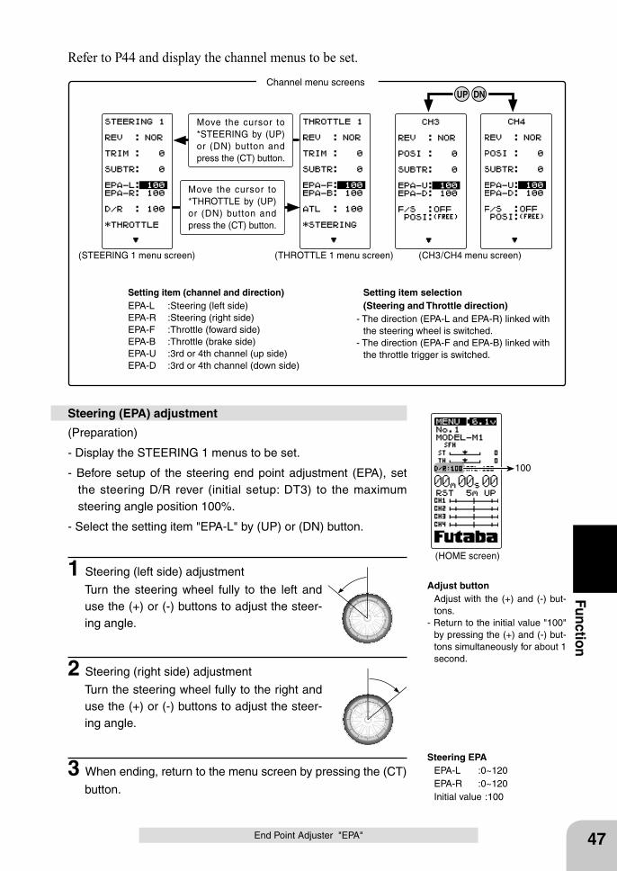
Setting item (channel and direction)EPA-L :Steering (left side)EPA-R :Steering (right side)EPA-F :Throttle (foward side)EPA-B :Throttle (brake side)EPA-U :3rd or 4th channel (up side)EPA-D :3rd or 4th channel (down side)
Setting item selection (Steering and Throttle direction) - The direction (EPA-L and EPA-R) linked with
the steering wheel is switched.- The direction (EPA-F and EPA-B) linked with
the throttle trigger is switched.
Move the cursor to *STEERING by (UP) or (DN) button and press the (CT) button.
Move the cursor to *THROTTLE by (UP) or (DN) button and press the (CT) button.
Channel menu screens
(HOME screen)
100
DNUP
47
Function
End Point Adjuster "EPA"
(Preparation)
- Display the STEERING 1 menus to be set.
- Before setup of the steering end point adjustment (EPA), set the steering D/R rever (initial setup: DT3) to the maximum steering angle position 100%.
- Select the setting item "EPA-L" by (UP) or (DN) button.
1 Steering (left side) adjustment
Turn the steering wheel fully to the left and use the (+) or (-) buttons to adjust the steer-ing angle.
2 Steering (right side) adjustment
Turn the steering wheel fully to the right and use the (+) or (-) buttons to adjust the steer-ing angle.
3 When ending, return to the menu screen by pressing the (CT)
button.
Steering (EPA) adjustment
Adjust button Adjust with the (+) and (-) but-
tons.- Return to the initial value "100"
by pressing the (+) and (-) but-tons simultaneously for about 1 second.
Steering EPA EPA-L :0~120 EPA-R :0~120 Initial value :100
Refer to P44 and display the channel menus to be set.
(HOME screen)
100
48
Function
End Point Adjuster "EPA"
(Preparation)
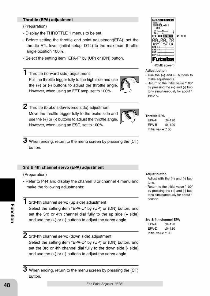
- Display the THROTTLE 1 menus to be set.
- Before setting the throttle end point adjustment(EPA), set the throttle ATL lever (initial setup: DT4) to the maximum throttle angle position 100%.
- Select the setting item "EPA-F" by (UP) or (DN) button.
1 Throttle (forward side) adjustment
Pull the throttle trigger fully to the high side and use the (+) or (-) buttons to adjust the throttle angle. However, when using an FET amp, set to 100%.
2 Throttle (brake side/reverse side) adjustment
Move the throttle trigger fully to the brake side and use the (+) or (-) buttons to adjust the throttle angle. However, when using an ESC, set to 100%.
3 When ending, return to the menu screen by pressing the (CT)
button.
Throttle (EPA) adjustment
(Preparation)
- Refer to P44 and display the channel 3 or channel 4 menu and make the following adjustments:
1 3rd/4th channel servo (up side) adjustment
Select the setting item "EPA-U" by (UP) or (DN) button, and set the 3rd or 4th channel dial fully to the up side (+ side) and use the (+) or (-) buttons to adjust the servo angle.
2 3rd/4th channel servo (down side) adjustment
Select the setting item "EPA-D" by (UP) or (DN) button, and set the 3rd or 4th channel dial fully to the down side (- side) and use the (+) or (-) buttons to adjust the servo angle.
3 When ending, return to the menu screen by pressing the (CT)
button.
3rd & 4th channel servo (EPA) adjustment
Adjust button- Use the (+) and (-) buttons to
make adjustments.- Return to the initial value "100"
by pressing the (+) and (-) but-tons simultaneously for about 1 second.
Throttle EPA EPA-F :0~120 EPA-B :0~120 Initial value :100
Adjust button Adjust with the (+) and (-) but-
tons.- Return to the initial value "100"
by pressing the (+) and (-) but-tons simultaneously for about 1 second.
3rd & 4th channel EPA EPA-U :0~120 EPA-D :0~120 Initial value :100
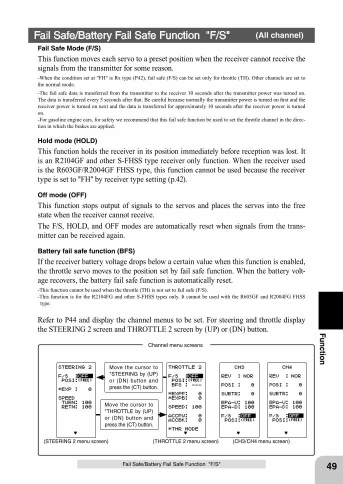
(STEERING 2 menu screen) (THROTTLE 2 menu screen) (CH3/CH4 menu screen)
Move the cursor to *STEERING by (UP) or (DN) button and press the (CT) button.
Move the cursor to *THROTTLE by (UP) or (DN) button and press the (CT) button.
Channel menu screens
49
Function
Fail Safe/Battery Fail Safe Function "F/S"
Fail Safe/Battery Fail Safe Function "F/S" (All channel)
Fail Safe Mode (F/S)
This function moves each servo to a preset position when the receiver cannot receive the signals from the transmitter for some reason.-When the condition set at "FH" is Rx type (P42), fail safe (F/S) can be set only for throttle (TH). Other channels are set to the normal mode.-The fail safe data is transferred from the transmitter to the receiver 10 seconds after the transmitter power was turned on. The data is transferred every 5 seconds after that. Be careful because normally the transmitter power is turned on first and the receiver power is turned on next and the data is transferred for approximately 10 seconds after the receiver power is turned on.-For gasoline engine cars, for safety we recommend that this fail safe function be used to set the throttle channel in the direc-tion in which the brakes are applied.
Hold mode (HOLD)
This function holds the receiver in its position immediately before reception was lost. It is an R2104GF and other S-FHSS type receiver only function. When the receiver used is the R603GF/R2004GF FHSS type, this function cannot be used because the receiver type is set to "FH" by receiver type setting (p.42).
Off mode (OFF)
This function stops output of signals to the servos and places the servos into the free state when the receiver cannot receive.The F/S, HOLD, and OFF modes are automatically reset when signals from the trans-mitter can be received again.
Battery fail safe function (BFS)
If the receiver battery voltage drops below a certain value when this function is enabled, the throttle servo moves to the position set by fail safe function. When the battery volt-age recovers, the battery fail safe function is automatically reset.-This function cannot be used when the throttle (TH) is not set to fail safe (F/S).-This function is for the R2104FG and other S-FHSS types only. It cannot be used with the R603GF and R2004FG FHSS type.
Refer to P44 and display the channel menus to be set. For steering and throttle display the STEERING 2 screen and THROTTLE 2 screen by (UP) or (DN) button.
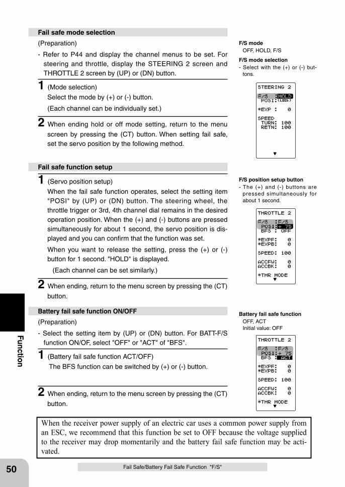
Battery fail safe function OFF, ACT Initial value: OFF
50
Function
Fail Safe/Battery Fail Safe Function "F/S"
When the receiver power supply of an electric car uses a common power supply from an ESC, we recommend that this function be set to OFF because the voltage supplied to the receiver may drop momentarily and the battery fail safe function may be acti-vated.
(Preparation)
- Refer to P44 and display the channel menus to be set. For steering and throttle, display the STEERING 2 screen and THROTTLE 2 screen by (UP) or (DN) button.
1 (Mode selection)
Select the mode by (+) or (-) button.
(Each channel can be individually set.)
2 When ending hold or off mode setting, return to the menu
screen by pressing the (CT) button. When setting fail safe, set the servo position by the following method.
Fail safe mode selection
(Preparation)
- Select the setting item by (UP) or (DN) button. For BATT-F/S function ON/OF, select "OFF" or "ACT" of "BFS".
1 (Battery fail safe function ACT/OFF)
The BFS function can be switched by (+) or (-) button.
2 When ending, return to the menu screen by pressing the (CT)
button.
Battery fail safe function ON/OFF
1 (Servo position setup)
When the fail safe function operates, select the setting item "POSI" by (UP) or (DN) button. The steering wheel, the throttle trigger or 3rd, 4th channel dial remains in the desired operation position. When the (+) and (-) buttons are pressed simultaneously for about 1 second, the servo position is dis-played and you can confirm that the function was set.
When you want to release the setting, press the (+) or (-) button for 1 second. "HOLD" is displayed.
(Each channel can be set similarly.)
2 When ending, return to the menu screen by pressing the (CT)
button.
Fail safe function setup
F/S position setup button- The (+) and (-) buttons are
pressed simultaneously for about 1 second.
F/S mode selection- Select with the (+) or (-) but-
tons.
F/S mode OFF, HOLD, F/S
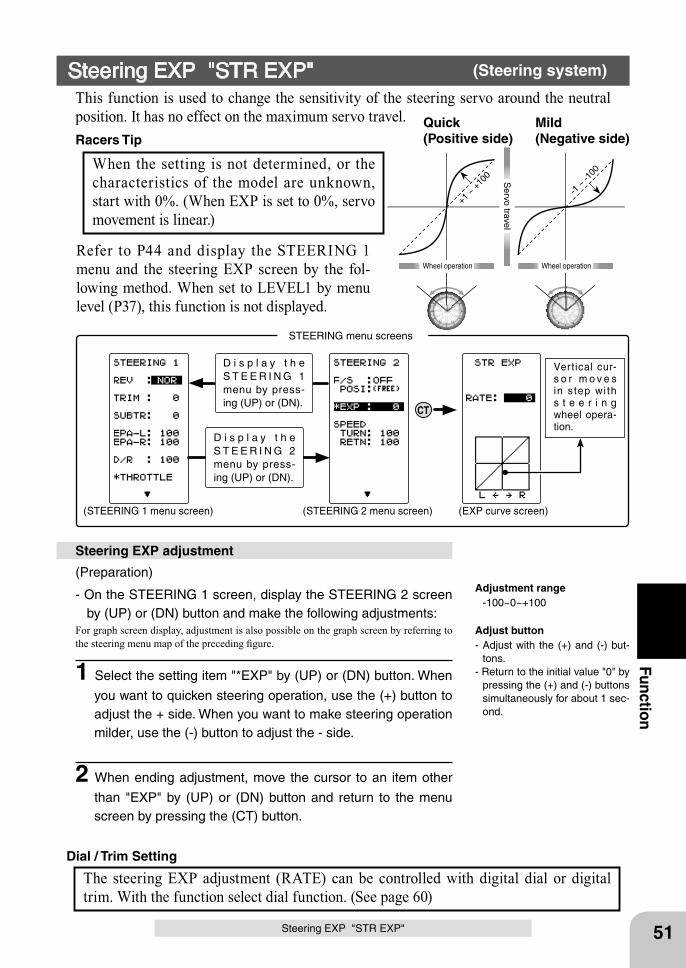
+1 ~
+10
0
-1 ~
-100
Wheel operation
Mild(Negative side)
Quick(Positive side)
Wheel operation
Servo travel
(STEERING 1 menu screen) (STEERING 2 menu screen) (EXP curve screen)
D i s p l a y t h e S T E E R I N G 1 menu by press-ing (UP) or (DN).
D i s p l a y t h e S T E E R I N G 2 menu by press-ing (UP) or (DN).
STEERING menu screens
CT
Vertical cur-s o r m o v e s in s tep wi th s t e e r i n g wheel opera-tion.
51
Function
Steering EXP "STR EXP"
Steering EXP "STR EXP" (Steering system)
This function is used to change the sensitivity of the steering servo around the neutral position. It has no effect on the maximum servo travel.
(Preparation)
- On the STEERING 1 screen, display the STEERING 2 screen by (UP) or (DN) button and make the following adjustments:
For graph screen display, adjustment is also possible on the graph screen by referring to the steering menu map of the preceding figure.
1 Select the setting item "*EXP" by (UP) or (DN) button. When
you want to quicken steering operation, use the (+) button to adjust the + side. When you want to make steering operation milder, use the (-) button to adjust the - side.
2 When ending adjustment, move the cursor to an item other
than "EXP" by (UP) or (DN) button and return to the menu screen by pressing the (CT) button.
Steering EXP adjustment
When the setting is not determined, or the characteristics of the model are unknown, start with 0%. (When EXP is set to 0%, servo movement is linear.)
Racers Tip
The steering EXP adjustment (RATE) can be controlled with digital dial or digital trim. With the function select dial function. (See page 60)
Dial / Trim Setting
Adjustment range -100~0~+100
Adjust button- Adjust with the (+) and (-) but-
tons.- Return to the initial value "0" by
pressing the (+) and (-) buttons simultaneously for about 1 sec-ond.
Refer to P44 and display the STEERING 1 menu and the steering EXP screen by the fol-lowing method. When set to LEVEL1 by menu level (P37), this function is not displayed.
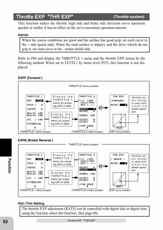
(THROTTLE1 menu screen) (THROTTLE 2 menu screen) (EXP curve screen)
D i s p l a y t h e T H R OT T L E 1 menu by press-ing (UP) or (DN).
D i s p l a y t h e T H R OT T L E 2 menu by press-ing (UP) or (DN).
THROTTLE menu screens
CT
Vertical cur-s o r m o v e s in s tep wi th s t e e r i n g wheel opera-tion.
(THROTTLE 1 menu screen) (THROTTLE 2 menu screen) (EXP curve screen)
D i s p l a y t h e T H R OT T L E 1 menu by press-ing (UP) or (DN).
D i s p l a y t h e T H ROT T L E 2 menu by press-ing (UP) or (DN).
THROTTLE menu screens
CT
Vertical cur-s o r m o v e s in s tep wi th s t e e r i n g wheel opera-tion.
52
Function
Throttle EXP "THR EXP"
Throttle EXP "THR EXP" (Throttle system)
This function makes the throttle high side and brake side direction servo operation quicker or milder. It has no effect on the servo maximum operation amount.
When the course conditions are good and the surface has good grip, set each curve to the + side (quick side). When the road surface is slippery and the drive wheels do not grip it, set each curve to the - minus (mild) side.
Advice
The throttle EXP adjustment (RATE) can be controlled with digital dial or digital trim, using the function select dial function. (See page 60)
Dial / Trim Setting
Refer to P44 and display the THROTTLE 1 menu and the throttle EXP screen by the following method. When set to LEVEL1 by menu level (P37), this function is not dis-played.
EXPF (Forward )
EXPB (Brake/ Reverse )
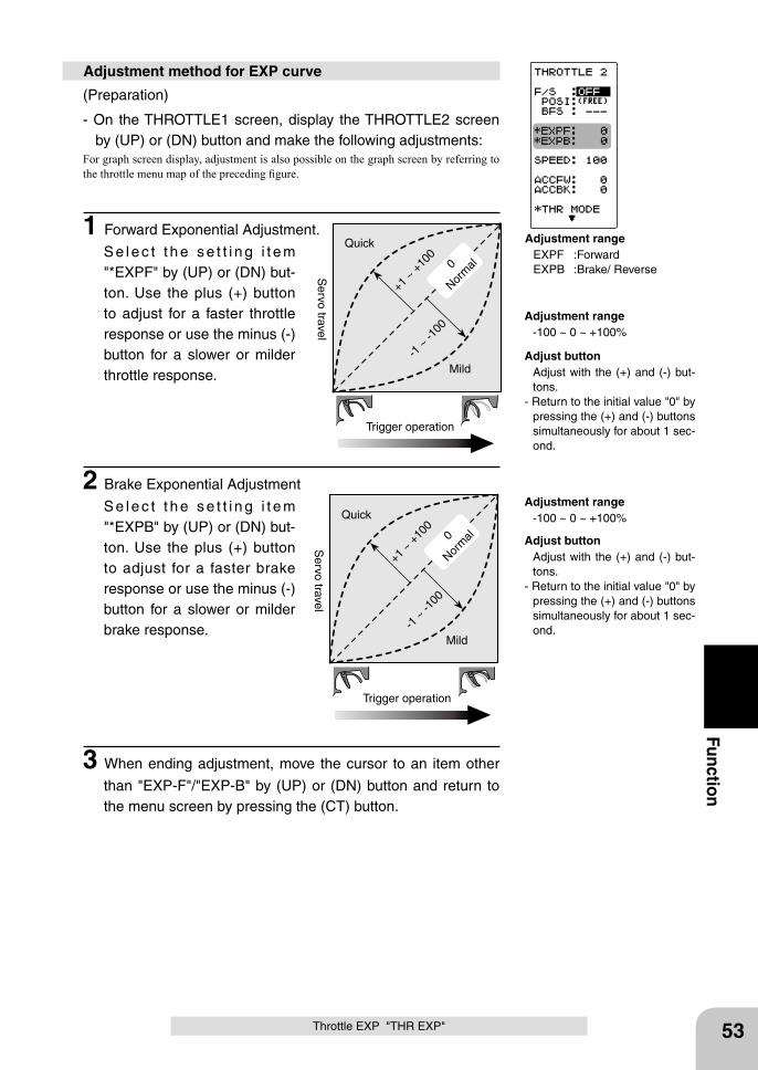
0
Norm
al
+1 ~
+10
0
Trigger operation
Quick
-1 ~
-100
Mild
Servo travel
0
Norm
al
+1 ~
+10
0
Trigger operation
Quick
-1 ~
-100
Mild
Servo travel
53
Function
Throttle EXP "THR EXP"
(Preparation)
- On the THROTTLE1 screen, display the THROTTLE2 screen by (UP) or (DN) button and make the following adjustments:
For graph screen display, adjustment is also possible on the graph screen by referring to the throttle menu map of the preceding figure.
1 Forward Exponential Adjustment.
S e l e c t t h e s e t t i n g i t e m "*EXPF" by (UP) or (DN) but-ton. Use the plus (+) button to adjust for a faster throttle response or use the minus (-) button for a slower or milder throttle response.
2 Brake Exponential Adjustment
S e l e c t t h e s e t t i n g i t e m "*EXPB" by (UP) or (DN) but-ton. Use the plus (+) button to adjust for a faster brake response or use the minus (-) button for a slower or milder brake response.
3 When ending adjustment, move the cursor to an item other
than "EXP-F"/"EXP-B" by (UP) or (DN) button and return to the menu screen by pressing the (CT) button.
Adjustment method for EXP curve
Adjustment range -100 ~ 0 ~ +100%
Adjustment range -100 ~ 0 ~ +100%
Adjustment range EXPF :Forward EXPB :Brake/ Reverse
Adjust button Adjust with the (+) and (-) but-
tons.- Return to the initial value "0" by
pressing the (+) and (-) buttons simultaneously for about 1 sec-ond.
Adjust button Adjust with the (+) and (-) but-
tons.- Return to the initial value "0" by
pressing the (+) and (-) buttons simultaneously for about 1 sec-ond.
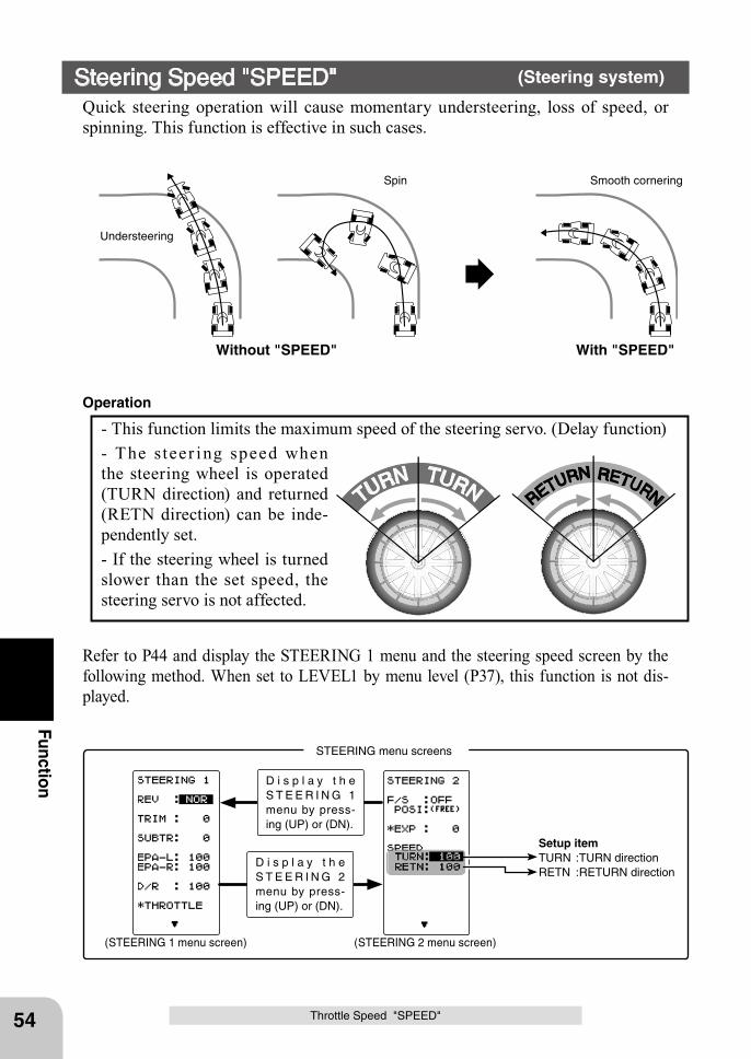
(STEERING 1 menu screen) (STEERING 2 menu screen)
D i s p l a y t h e S T E E R I N G 1 menu by press-ing (UP) or (DN).
D i s p l a y t h e S T E E R I N G 2 menu by press-ing (UP) or (DN).
STEERING menu screens
Setup itemTURN :TURN directionRETN :RETURN direction
54
Function
Throttle Speed "SPEED"
Without "SPEED" With "SPEED"
Understeering
Smooth corneringSpin
TURN TURNRETURN RETURN
- This function limits the maximum speed of the steering servo. (Delay function) - The steer ing speed when the steering wheel is operated (TURN direction) and returned (RETN direction) can be inde-pendently set. - If the steering wheel is turned slower than the set speed, the steering servo is not affected.
Operation
Steering Speed "SPEED" (Steering system)
Quick steering operation will cause momentary understeering, loss of speed, or spinning. This function is effective in such cases.
Refer to P44 and display the STEERING 1 menu and the steering speed screen by the following method. When set to LEVEL1 by menu level (P37), this function is not dis-played.
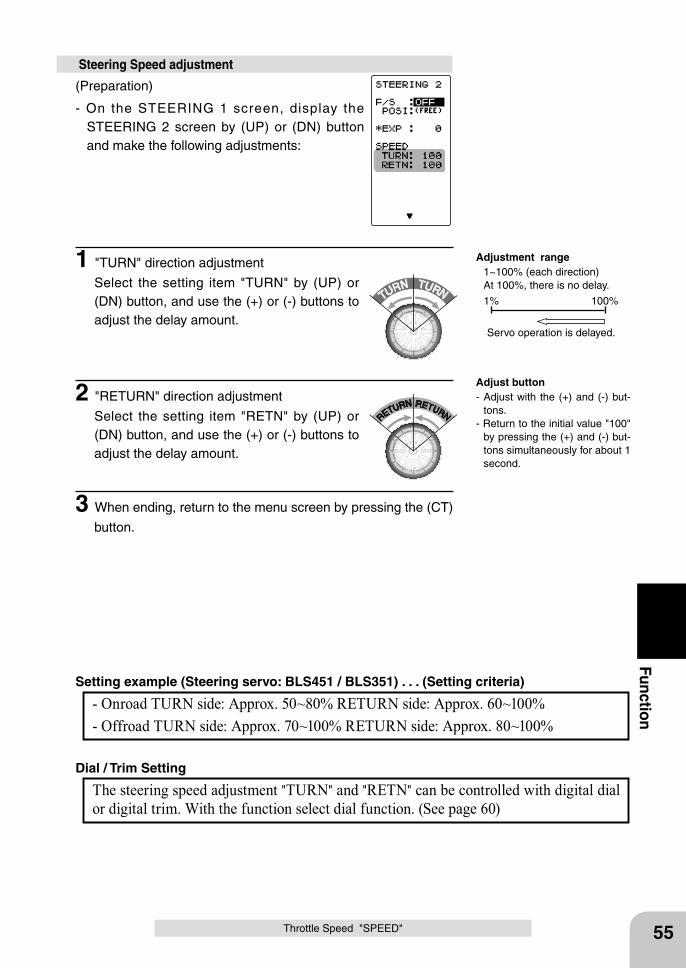
TURN TURN
RETURN RETURN
55
Function
(Preparation)
- On the STEERING 1 screen, display the STEERING 2 screen by (UP) or (DN) button and make the following adjustments:
1 "TURN" direction adjustment
Select the setting item "TURN" by (UP) or (DN) button, and use the (+) or (-) buttons to adjust the delay amount.
2 "RETURN" direction adjustment
Select the setting item "RETN" by (UP) or (DN) button, and use the (+) or (-) buttons to adjust the delay amount.
3 When ending, return to the menu screen by pressing the (CT)
button.
Steering Speed adjustment
100%1%
Servo operation is delayed.
- Onroad TURN side: Approx. 50~80% RETURN side: Approx. 60~100% - Offroad TURN side: Approx. 70~100% RETURN side: Approx. 80~100%
Setting example (Steering servo: BLS451 / BLS351) . . . (Setting criteria)
Adjust button- Adjust with the (+) and (-) but-
tons.- Return to the initial value "100"
by pressing the (+) and (-) but-tons simultaneously for about 1 second.
The steering speed adjustment "TURN" and "RETN" can be controlled with digital dial or digital trim. With the function select dial function. (See page 60)
Dial / Trim Setting
Adjustment range 1~100% (each direction) At 100%, there is no delay.
Throttle Speed "SPEED"
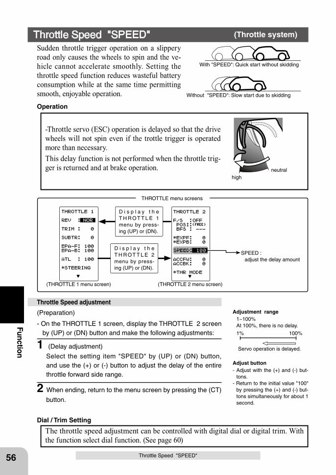
highneutral
(THROTTLE 1 menu screen) (THROTTLE 2 menu screen)
D i s p l a y t h e T H R OT T L E 1 menu by press-ing (UP) or (DN).
D i s p l a y t h e T H R OT T L E 2 menu by press-ing (UP) or (DN).
THROTTLE menu screens
SPEED : adjust the delay amount
With "SPEED": Quick start without skidding
Without "SPEED": Slow start due to skidding
56
Function
Throttle Speed "SPEED"
(Preparation)
- On the THROTTLE 1 screen, display the THROTTLE 2 screen by (UP) or (DN) button and make the following adjustments:
1 (Delay adjustment)
Select the setting item "SPEED" by (UP) or (DN) button, and use the (+) or (-) button to adjust the delay of the entire throttle forward side range.
2 When ending, return to the menu screen by pressing the (CT)
button.
Throttle Speed adjustment
Adjust button- Adjust with the (+) and (-) but-
tons.- Return to the initial value "100"
by pressing the (+) and (-) but-tons simultaneously for about 1 second.
The throttle speed adjustment can be controlled with digital dial or digital trim. With the function select dial function. (See page 60)
Dial / Trim Setting
-Throttle servo (ESC) operation is delayed so that the drive wheels will not spin even if the trottle trigger is operated more than necessary. This delay function is not performed when the throttle trig-ger is returned and at brake operation.
Operation
Throttle Speed "SPEED" (Throttle system)
Sudden throttle trigger operation on a slippery road only causes the wheels to spin and the ve-hicle cannot accelerate smoothly. Setting the throttle speed function reduces wasteful battery consumption while at the same time permitting smooth, enjoyable operation.
100%1%
Servo operation is delayed.
Adjustment range 1~100% At 100%, there is no delay.
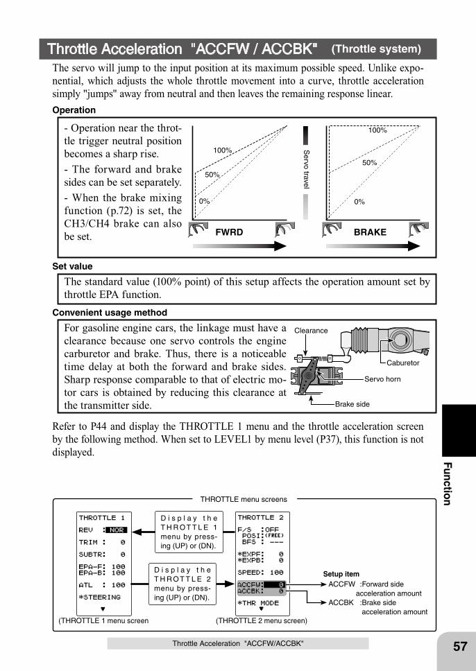
(THROTTLE 1 menu screen (THROTTLE 2 menu screen)
D i s p l a y t h e T H R OT T L E 1 menu by press-ing (UP) or (DN).
D i s p l a y t h e T H R OT T L E 2 menu by press-ing (UP) or (DN).
THROTTLE menu screens
57
Function
Throttle Acceleration "ACCFW/ACCBK"
Caburetor
Brake side
Servo horn
Clearance
FWRD
Servo travel
BRAKE
0%
50%
100%
0%
50%
100%
Setup item ACCFW :Forward side acceleration amount ACCBK :Brake side
acceleration amount
- Operation near the throt-tle trigger neutral position becomes a sharp rise.- The forward and brake sides can be set separately.- When the brake mixing function (p.72) is set, the CH3/CH4 brake can also be set.
Operation
Throttle Acceleration "ACCFW / ACCBK" (Throttle system)
The servo will jump to the input position at its maximum possible speed. Unlike expo-nential, which adjusts the whole throttle movement into a curve, throttle acceleration simply "jumps" away from neutral and then leaves the remaining response linear.
The standard value (100% point) of this setup affects the operation amount set by throttle EPA function.
Set value
For gasoline engine cars, the linkage must have a clearance because one servo controls the engine carburetor and brake. Thus, there is a noticeable time delay at both the forward and brake sides. Sharp response comparable to that of electric mo-tor cars is obtained by reducing this clearance at the transmitter side.
Convenient usage method
Refer to P44 and display the THROTTLE 1 menu and the throttle acceleration screen by the following method. When set to LEVEL1 by menu level (P37), this function is not displayed.
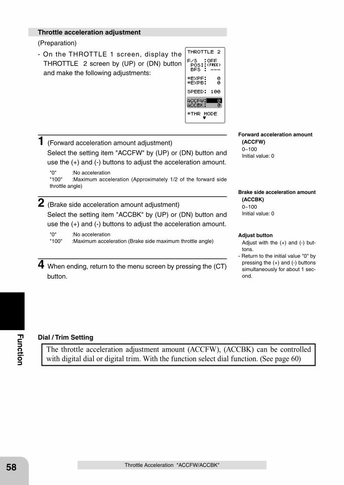
58
Function
Throttle Acceleration "ACCFW/ACCBK"
(Preparation)
- On the THROTTLE 1 screen, display the THROTTLE 2 screen by (UP) or (DN) button and make the following adjustments:
1 (Forward acceleration amount adjustment)
Select the setting item "ACCFW" by (UP) or (DN) button and use the (+) and (-) buttons to adjust the acceleration amount.
"0" :No acceleration"100" :Maximum acceleration (Approximately 1/2 of the forward side throttle angle)
2 (Brake side acceleration amount adjustment)
Select the setting item "ACCBK" by (UP) or (DN) button and use the (+) and (-) buttons to adjust the acceleration amount.
"0" :No acceleration"100" :Maximum acceleration (Brake side maximum throttle angle)
4 When ending, return to the menu screen by pressing the (CT)
button.
Throttle acceleration adjustment
The throttle acceleration adjustment amount (ACCFW), (ACCBK) can be controlled with digital dial or digital trim. With the function select dial function. (See page 60)
Dial / Trim Setting
Adjust button Adjust with the (+) and (-) but-
tons.- Return to the initial value "0" by
pressing the (+) and (-) buttons simultaneously for about 1 sec-ond.
Forward acceleration amount (ACCFW) 0~100 Initial value: 0
Brake side acceleration amount (ACCBK) 0~100 Initial value: 0
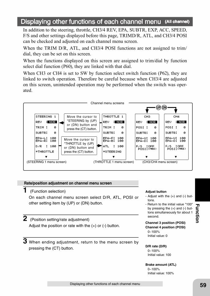
DNUP
Move the cursor to *STEERING by (UP) or (DN) button and press the (CT) button.
Move the cursor to *THROTTLE by (UP) or (DN) button and press the (CT) button.
Channel menu screens
(STEERING 1 menu screen) (THROTTLE 1 menu screen) (CH3/CH4 menu screen)
59
Function
Displaying other functions of each channel menu
Displaying other functions of each channel menu (All channel)
In addition to the steering, throttle, CH3/4 REV, EPA, SUBTR, EXP, ACC, SPEED, F/S and other settings displayed before this page, TRIMD/R, ATL, and CH3/4 POSI can be checked and adjusted on each channel menu screen.When the TRIM D/R, ATL, and CH3/4 POSI functions are not assigned to trim/dial, they can be set on this screen.When the functions displayed on this screen are assigned to trim/dial by function select dial function (P60), they are linked with that dial.When CH3 or CH4 is set to SW by function select switch function (P62), they are linked to switch operation. Therefore be careful because when CH3/4 are adjusted on this screen, unintended operation may be performed when the switch was oper-ated.
1 (Function selection)
On each channel menu screen select D/R, ATL, POSI or other setting item by (UP) or (DN) button.
2 (Position setting/rate adjustment)
Adjust the position or rate with the (+) or (-) button.
3 When ending adjustment, return to the menu screen by
pressing the (CT) button.
Rate/position adjustment on channel menu screen
Adjust button- Adjust with the (+) and (-) but-
tons.- Return to the initial value "100"
by pressing the (+) and (-) but-tons simultaneously for about 1 second.
Channel 3 position (POSI)Channel 4 position (POSI) 0~100% Initial value: 0
D/R rate (D/R) 0~100% Initial value: 100
Brake amount (ATL) 0~100% Initial value: 100%
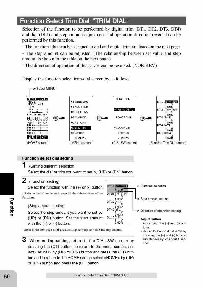
CT CTCT
(HOME screen) (MENU screen) (DIAL SW screen) (Function Trim Dial screen)
Select MENU
Function selection
Direction of operation setting
Step amount setting
60
Function
Function Select Trim Dial "TRIM DIAL"Selection of the function to be performed by digital trim (DT1, DT2, DT3, DT4) and dial (DL1) and step amount adjustment and operation direction reversal can be performed by this function.- The functions that can be assigned to dial and digital trim are listed on the next page.- The step amount can be adjusted. (The relationship between set value and step amount is shown in the table on the next page.)- The direction of operation of the servos can be reversed. (NOR/REV)
Display the function select trim/dial screen by as follows:
1 (Setting dial/trim selection)
Select the dial or trim you want to set by (UP) or (DN) button.
2 (Function setting)
Select the function with the (+) or (-) button.
- Refer to the list on the next page for the abbreviations of the functions.
(Step amount setting)
Select the step amount you want to set by (UP) or (DN) button. Set the step amount with the (+) or (-) button.
- Refer to the next page for the relationship between set value and step amount.
3 When ending setting, return to the DIAL SW screen by
pressing the (CT) button. To return to the menu screen, se-lect <MENU> by (UP) or (DN) button and press the (CT) but-ton and to return to the HOME screen select <HOME> by (UP) or (DN) button and press the (CT) button.
Function select dial setting
Function Select Trim Dial "TRIM DIAL"
Adjust button Adjust with the (+) and (-) but-
tons.- Return to the initial value "2" by
pressing the (+) and (-) buttons simultaneously for about 1 sec-ond.
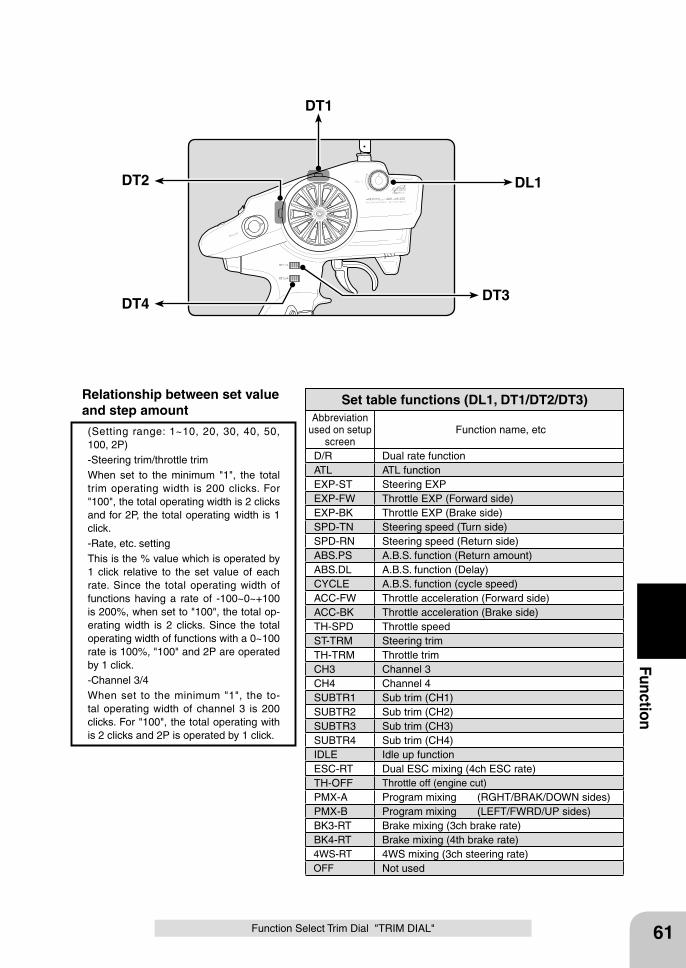
DT2
DT3DT4
DT1
DL1
61
Function
Abbreviation used on setup
screenFunction name, etc
D/R Dual rate functionATL ATL functionEXP-ST Steering EXPEXP-FW Throttle EXP (Forward side)EXP-BK Throttle EXP (Brake side)SPD-TN Steering speed (Turn side)SPD-RN Steering speed (Return side)ABS.PS A.B.S. function (Return amount)ABS.DL A.B.S. function (Delay)CYCLE A.B.S. function (cycle speed)ACC-FW Throttle acceleration (Forward side)ACC-BK Throttle acceleration (Brake side)TH-SPD Throttle speed ST-TRM Steering trimTH-TRM Throttle trimCH3 Channel 3CH4 Channel 4SUBTR1 Sub trim (CH1)SUBTR2 Sub trim (CH2)SUBTR3 Sub trim (CH3)SUBTR4 Sub trim (CH4)IDLE Idle up functionESC-RT Dual ESC mixing (4ch ESC rate)TH-OFF Throttle off (engine cut)PMX-A Program mixing (RGHT/BRAK/DOWN sides)PMX-B Program mixing (LEFT/FWRD/UP sides)BK3-RT Brake mixing (3ch brake rate)BK4-RT Brake mixing (4th brake rate)4WS-RT 4WS mixing (3ch steering rate)OFF Not used
Set table functions (DL1, DT1/DT2/DT3)
(Setting range: 1~10, 20, 30, 40, 50, 100, 2P)-Steering trim/throttle trimWhen set to the minimum "1", the total trim operating width is 200 clicks. For "100", the total operating width is 2 clicks and for 2P, the total operating width is 1 click.-Rate, etc. settingThis is the % value which is operated by 1 click relative to the set value of each rate. Since the total operating width of functions having a rate of -100~0~+100 is 200%, when set to "100", the total op-erating width is 2 clicks. Since the total operating width of functions with a 0~100 rate is 100%, "100" and 2P are operated by 1 click.-Channel 3/4When set to the minimum "1", the to-tal operating width of channel 3 is 200 clicks. For "100", the total operating with is 2 clicks and 2P is operated by 1 click.
Relationship between set value and step amount
Function Select Trim Dial "TRIM DIAL"
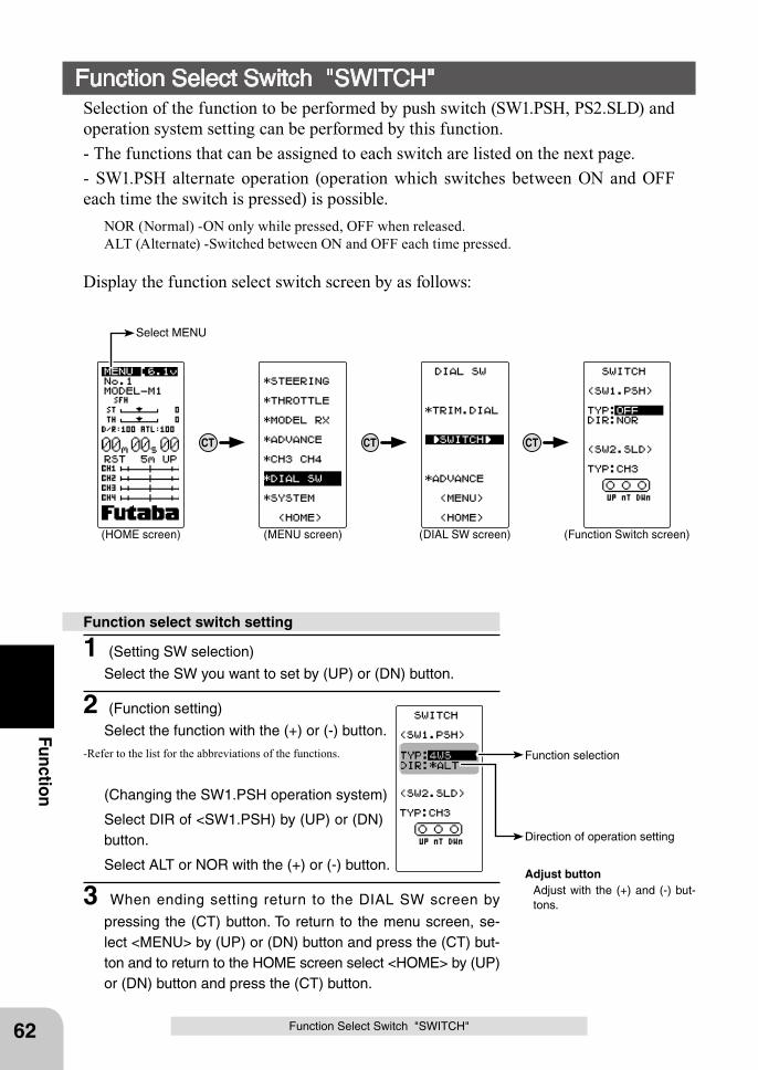
CT CTCT
(HOME screen) (MENU screen) (DIAL SW screen) (Function Switch screen)
Select MENU
Function selection
Direction of operation setting
62
Function
Function Select Switch "SWITCH"Selection of the function to be performed by push switch (SW1.PSH, PS2.SLD) and operation system setting can be performed by this function.- The functions that can be assigned to each switch are listed on the next page.- SW1.PSH alternate operation (operation which switches between ON and OFF each time the switch is pressed) is possible.
NOR (Normal) -ON only while pressed, OFF when released.ALT (Alternate) -Switched between ON and OFF each time pressed.
Display the function select switch screen by as follows:
1 (Setting SW selection)
Select the SW you want to set by (UP) or (DN) button.
2 (Function setting)
Select the function with the (+) or (-) button.
-Refer to the list for the abbreviations of the functions.
(Changing the SW1.PSH operation system)
Select DIR of <SW1.PSH) by (UP) or (DN) button.
Select ALT or NOR with the (+) or (-) button.
3 When ending setting return to the DIAL SW screen by
pressing the (CT) button. To return to the menu screen, se-lect <MENU> by (UP) or (DN) button and press the (CT) but-ton and to return to the HOME screen select <HOME> by (UP) or (DN) button and press the (CT) button.
Function select switch setting
Function Select Switch "SWITCH"
Adjust button Adjust with the (+) and (-) but-
tons.
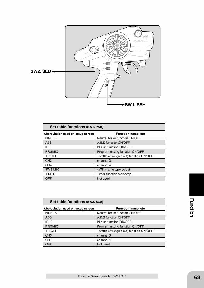
Abbreviation used on setup screen Function name, etcNT-BRK Neutral brake function ON/OFFABS A.B.S function ON/OFFIDLE Idle up function ON/OFFPRGMIX Program mixing function ON/OFFTH-OFF Throttle off (engine cut) function ON/OFFCH3 channel 3CH4 channel 44WS MIX 4WS mixing type selectTIMER Timer function start/stopOFF Not used
Set table functions (SW1. PSH)
Abbreviation used on setup screen Function name, etcNT-BRK Neutral brake function ON/OFFABS A.B.S function ON/OFFIDLE Idle up function ON/OFFPRGMIX Program mixing function ON/OFFTH-OFF Throttle off (engine cut) function ON/OFFCH3 channel 3CH4 channel 4OFF Not used
Set table functions (SW2. SLD)
SW2. SLD
SW1. PSH
63
Function
Function Select Switch "SWITCH"
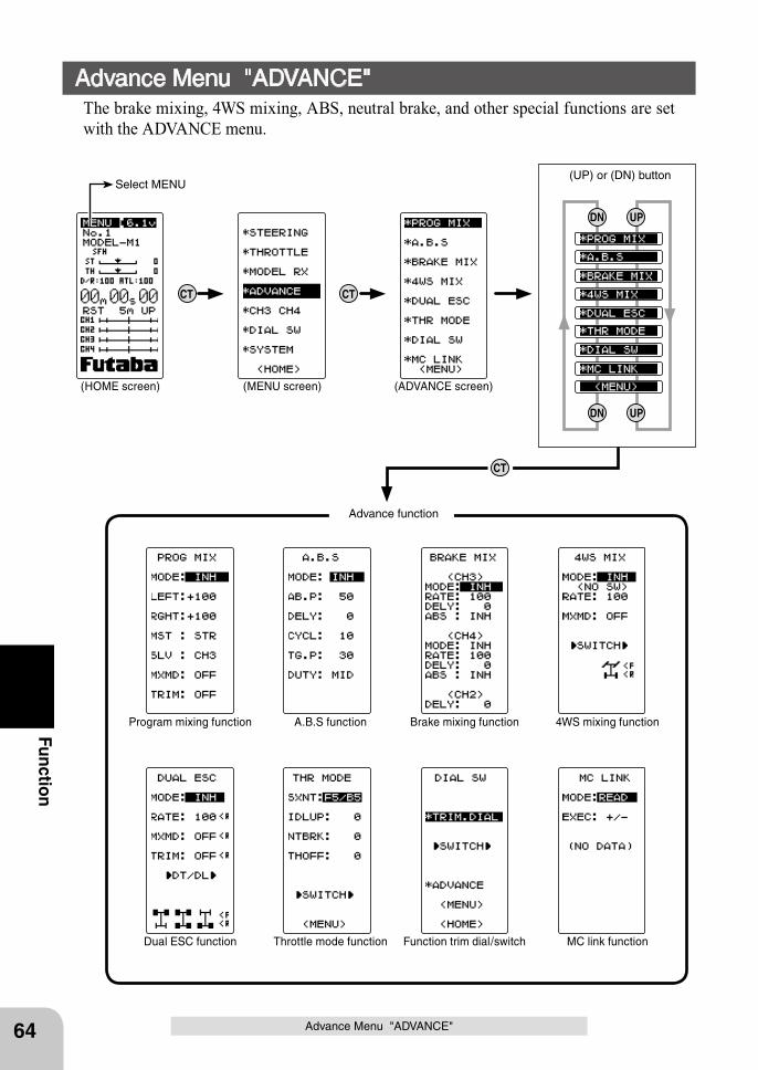
CT
CT
CT
UPDN
UPDN
(HOME screen) (MENU screen) (ADVANCE screen)
Select MENU(UP) or (DN) button
Function trim dial/switch
Brake mixing function
Dual ESC function
Program mixing function
Throttle mode function
A.B.S function
MC link function
4WS mixing function
Advance function
64
Function
Advance Menu "ADVANCE"
Advance Menu "ADVANCE"The brake mixing, 4WS mixing, ABS, neutral brake, and other special functions are set with the ADVANCE menu.
65
Function
Advance Menu "ADVANCE"
Program mixing PRG MIXMixing can be applied between the steering, throttle, channel 3, and channel 4 chan-nels.
A.B.S function [ABS]Pumping brake operation, which brakes the throttle servo intermittently at brake op-eration, can be set.
Brake mixing [BRAKE MIX]This function is used when the front and rear brakes are independent and are adjusted individually such as a 1/5GP car.
4WS mixing [4WS MIX]This function can be used with crawlers and other 4WS type vehicles. It is mixing which controls front side steering by CH1 and rear side steering by CH3.
Dual ESC [DUAL ESC]This function is mixing used when the front and rear drive motor controllers of a crawler or similar vehicle are used independently.
Throttle mode [THR MODE]This menu contains the following throttle functions:SXNT (Neutral position)
The forward and brake (back) operation ratio can be selected from 7:3 and 5:5 by changing the neutral position of the throttle servo.
IDLUP (Idle up)This function is used to improve engine starting performance by raising the idling speed when the engine of a gasoline car (boat) is started.
NTBRK (Neutral brake)The neutral brake position, which applies the brakes at the neutral position of the trigger, can be set.
THOFF (Throttle off)This function stops the engine of a boat, etc. by operating the throttle servo to the set position by switch regardless of the throttle trigger position.
Function trim dial/switch [DIAL SW]Refer to the function trim dial and function switch described on P60 to P63.
MC link [MC LINK]This is a special function which allows Futaba motor controller (MC) data changes to be set by the T4PL transmitter (MC950CR, MC851C, MC602C, MC02R, etc.).
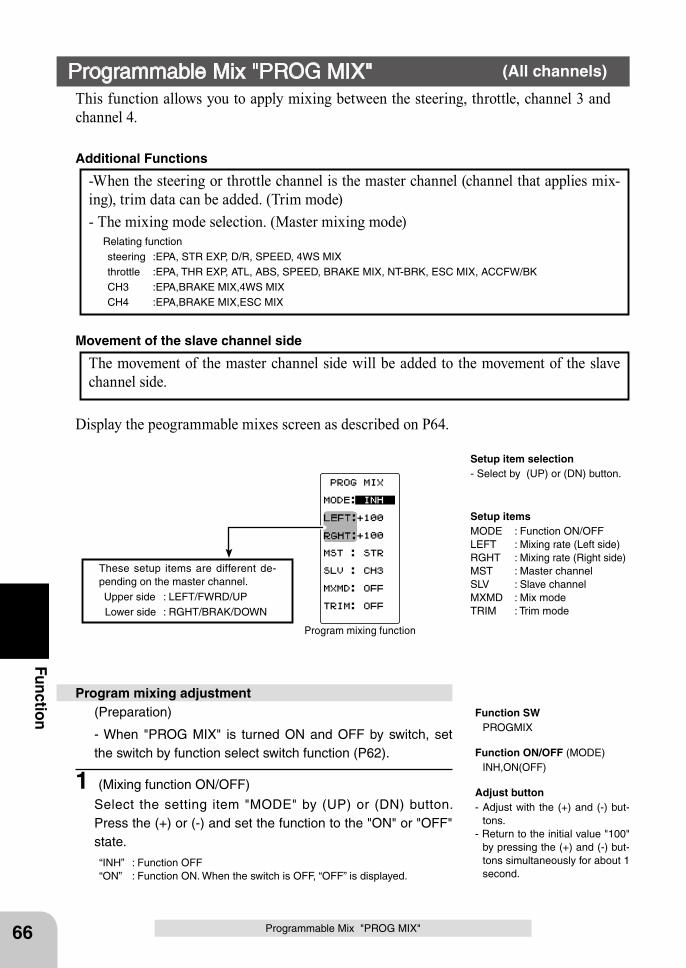
These setup items are different de-pending on the master channel. Upper side : LEFT/FWRD/UP Lower side : RGHT/BRAK/DOWN
Program mixing function
66
Function
Programmable Mix "PROG MIX"
Setup item selection- Select by (UP) or (DN) button.
This function allows you to apply mixing between the steering, throttle, channel 3 and channel 4.
-When the steering or throttle channel is the master channel (channel that applies mix-ing), trim data can be added. (Trim mode)- The mixing mode selection. (Master mixing mode) Relating function
steering :EPA, STR EXP, D/R, SPEED, 4WS MIXthrottle :EPA, THR EXP, ATL, ABS, SPEED, BRAKE MIX, NT-BRK, ESC MIX, ACCFW/BKCH3 :EPA,BRAKE MIX,4WS MIXCH4 :EPA,BRAKE MIX,ESC MIX
Additional Functions
The movement of the master channel side will be added to the movement of the slave channel side.
Movement of the slave channel side
Programmable Mix "PROG MIX" (All channels)
Setup itemsMODE : Function ON/OFFLEFT : Mixing rate (Left side)RGHT : Mixing rate (Right side)MST : Master channelSLV : Slave channelMXMD : Mix modeTRIM : Trim mode
Adjust button- Adjust with the (+) and (-) but-
tons.- Return to the initial value "100"
by pressing the (+) and (-) but-tons simultaneously for about 1 second.
Display the peogrammable mixes screen as described on P64.
Function ON/OFF (MODE) INH,ON(OFF)
Function SW PROGMIX
Program mixing adjustment(Preparation)
- When "PROG MIX" is turned ON and OFF by switch, set the switch by function select switch function (P62).
1 (Mixing function ON/OFF)
Select the setting item "MODE" by (UP) or (DN) button. Press the (+) or (-) and set the function to the "ON" or "OFF" state.
“INH” : Function OFF“ON” : Function ON. When the switch is OFF, “OFF” is displayed.
67
Function
Programmable Mix "PROG MIX"
Mixing amount -120~0~+120 Initial value: +100
Channel selection (MST) STR, THR, CH3, CH4 Initial value :STR
Channel selection (SLV) STR, THR, CH3, CH4 Initial value :CH3
Mixing mode (MXD) OFF, ON Initial value: OFF
Mixing amount -120~0~+120 Initial value: +100
Trim mode (TRIM) OFF, ON Initial value: OFF
2 (Master channel)
Select setup item "MST" by (UP) or (DN) button, and select the master channel by pressing the (+) or (-) button.
3 (Slave channel)
Select setup item "SLV" by (UP) or (DN) button, and select the slave channel by pressing the (+) or (-) button.
4 (Left, forward or up side mixing amount adjustment)
Select the setting item "LEFT", "FWRD", or "UP" by (UP) or (DN) button. Use the (+) or (-) button and adjust the left, for-ward, or up side mixing amount.
5 (Right, brake or down side mixing amount adjustment)
Select the setting item "RGHT", "BRAK", or "DOWN" by (UP) or (DN) button. Use the (+) or (-) button and adjust the right, brake, or down side mixing amount.
6 (Mixing mode setup)
Select setup item "MXMD" by (UP) or (DN) button, and use the (+) or (-) button to select the mixing mode.
"OFF" :Mixing proportional to master channel operation."MIX" :Mixing by master channel another function considered.
7 (Trim mode setup)
Select setup item "TRIM" by (UP) or (DN) button, and use the (+) or (-) button to select the mixing mode.
"OFF" :Trim is removed."ON" :Trim is added.
8 When ending, return to the ADVANCE menu screen by
pressing the (CT) button.
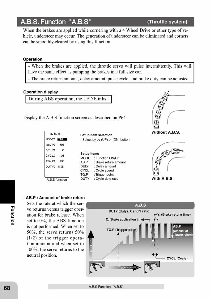
Servo travel
Trigger operation
AB.P(Amount of
brake return)TG.P (Trigger point)
CYCL (Cycle)
DUTY (duty): X and Y ratio
X: (Brake application time)
Y: (Brake return time)
A.B.S
A.B.S function
68
Function- AB.P : Amount of brake return
Sets the rate at which the ser-vo returns versus trigger oper-ation for brake release. When set to 0%, the ABS function is not performed. When set to 50%, the servo returns 50% (1/2) of the t r igger opera-tion amount and when set to 100%, the servo returns to the neutral position.
With A.B.S.
Without A.B.S.
A.B.S Function "A.B.S"
- When the brakes are applied, the throttle servo will pulse intermittently. This will have the same effect as pumping the brakes in a full size car. - The brake return amount, delay amount, pulse cycle, and brake duty can be adjusted.
Operation
Setup itemsMODE : Function ON/OffAB.P : Brake return amountDELY : Delay amountCYCL : Cycle speedTG.P : Trigger pointDUTY : Cycle duty ratio
A.B.S. Function "A.B.S" (Throttle system)
When the brakes are applied while cornering with a 4 Wheel Drive or other type of ve-hicle, understeer may occur. The generation of understeer can be eliminated and corners can be smoothly cleared by using this function.
During ABS operation, the LED blinks.Operation display
Display the A.B.S function screen as described on P64.
Setup item selection- Select by by (UP) or (DN) button.
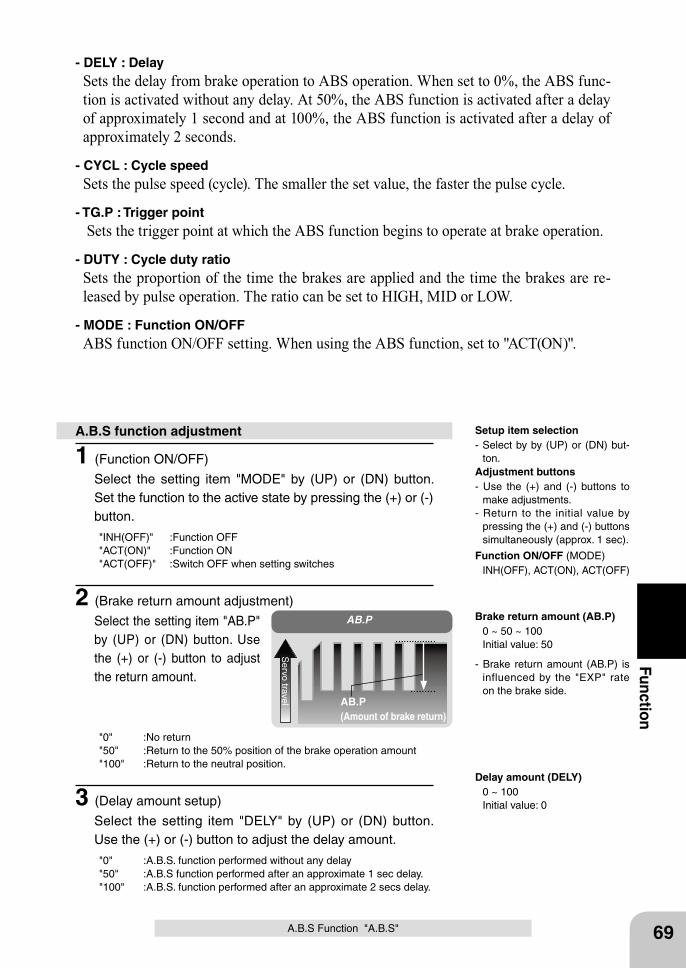
AB.P(Amount of brake return)
AB.P
Servo travel
69
Function
A.B.S Function "A.B.S"
- DELY : DelaySets the delay from brake operation to ABS operation. When set to 0%, the ABS func-tion is activated without any delay. At 50%, the ABS function is activated after a delay of approximately 1 second and at 100%, the ABS function is activated after a delay of approximately 2 seconds.
- CYCL : Cycle speedSets the pulse speed (cycle). The smaller the set value, the faster the pulse cycle.
- TG.P : Trigger pointSets the trigger point at which the ABS function begins to operate at brake operation.
- DUTY : Cycle duty ratioSets the proportion of the time the brakes are applied and the time the brakes are re-leased by pulse operation. The ratio can be set to HIGH, MID or LOW.
- MODE : Function ON/OFFABS function ON/OFF setting. When using the ABS function, set to "ACT(ON)".
1 (Function ON/OFF)
Select the setting item "MODE" by (UP) or (DN) button. Set the function to the active state by pressing the (+) or (-) button.
"INH(OFF)" :Function OFF"ACT(ON)" :Function ON"ACT(OFF)" :Switch OFF when setting switches
2 (Brake return amount adjustment)
Select the setting item "AB.P" by (UP) or (DN) button. Use the (+) or (-) button to adjust the return amount.
"0" :No return"50" :Return to the 50% position of the brake operation amount"100" :Return to the neutral position.
3 (Delay amount setup)
Select the setting item "DELY" by (UP) or (DN) button. Use the (+) or (-) button to adjust the delay amount.
"0" :A.B.S. function performed without any delay"50" :A.B.S function performed after an approximate 1 sec delay."100" :A.B.S. function performed after an approximate 2 secs delay.
A.B.S function adjustment
- Brake return amount (AB.P) is influenced by the "EXP" rate on the brake side.
Delay amount (DELY) 0 ~ 100 Initial value: 0
Adjustment buttons- Use the (+) and (-) buttons to
make adjustments.- Return to the initial value by
pressing the (+) and (-) buttons simultaneously (approx. 1 sec).
Brake return amount (AB.P) 0 ~ 50 ~ 100 Initial value: 50
Function ON/OFF (MODE) INH(OFF), ACT(ON), ACT(OFF)
Setup item selection- Select by by (UP) or (DN) but-
ton.
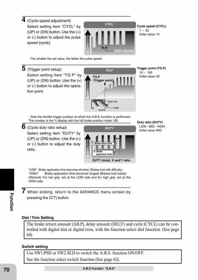
DUTY
Servo travel
DUTY (duty): X and Y ratio
X: (Brake application time)
Y: (Brake return time
TG.P
Servo travel
TG.P (Trigger point)
TGP
Brake side
Neutral
CYCL
Servo travel
CYCL (Cycle)
70
Function
A.B.S Function "A.B.S"A.B.S Function "A.B.S"
Duty ratio (DUTY) LOW - MID - HIGH Initial value: MID
Use SW1.PSH or SW2.SLD to switch the A.B.S. function ON/OFF.See the function select switch function (See page 62).
Switch setting
The brake return amount (AB.P), delay amount (DELY) and cycle (CYCL) can be con-trolled with digital dial or digital trim, with the function select dial function. (See page 60)
Dial / Trim Setting
4 (Cycle speed adjustment)
Select setting item "CYCL" by (UP) or (DN) button. Use the (+) or (-) button to adjust the pulse speed (cycle).
- The smaller the set value, the faster the pulse speed.
5 (Trigger point setup)
Select setting item "TG.P" by (UP) or (DN) button. Use the (+) or (-) button to adjust the opera-tion point.
- Sets the throttle trigger position at which the A.B.S. function is performed. The number is the % display with the full brake position made 100.
6 (Cycle duty ratio setup)
Select setting item "DUTY" by (UP) or (DN) button. Use the (+) or (-) button to adjust the duty ratio.
"LOW" :Brake application time becomes shortest. (Brakes lock with difficulty)"HIGH" :Brake application time becomes longest (Brakes lock easily)(Remark) For low grip, set at the LOW side and for high grip, set at the HIGH side.
7 When ending, return to the ADVANCE menu screen by
pressing the (CT) button.
Trigger point (TG.P) 10 ~ 100 Initial value: 30
Cycle speed (CYCL) 1 ~ 30 Initial value: 10
71
Function
A.B.S Function "A.B.S"
When the T4PL is used with the Futaba fail safe unit (FSU-1), it will operate as de-scribed below. However, FSU-1 cannot be used at the high speed mode.- When the FSU-1 is connected to the throttle channel, and the A.B.S. function has been activated, the FSU-1 LED will flash each time the servo operates. The reason for this is that the FSU-1 responds to sudden data changes caused by A.B.S. function pumping operation. It does not mean that the fail safe function is activated. The servo will not be affected.
Fail Safe Unit
- Basic settingAB.P: Approx. 30% (If this value is too high, the braking distance will increase.)CYCL: 5~7DUTY: (When grip is low: LOW side, when grip is high: HIGH side)DELY: 10~15%TG.P: Approx. 70%- When the wheels lock, or the car spins, when the brakes are applied fullyAB.P: Increase from 30%DUTY: Shift to "LOW" sideDELY: Reduce the delay - When the braking effect is poor and the braking distance is long when the brakes are applied fullyAB.P: Decrease from 30%DUTY: Shift to "HIGH" sideDELY: Increase the delay
Example of A.B.S. function setting when BLS351 / BLS352 used (There will be a slight difference depending on the state of the linkage.)
ABS can be independently set for the brakes which are controlled by the 3rd CH and 4th CH by using the brake mixing (BRAKE) function described on page 72. For more information, read the brake mixing (BRAKE) item.
1/5 scale car and other independent brakes and ABS
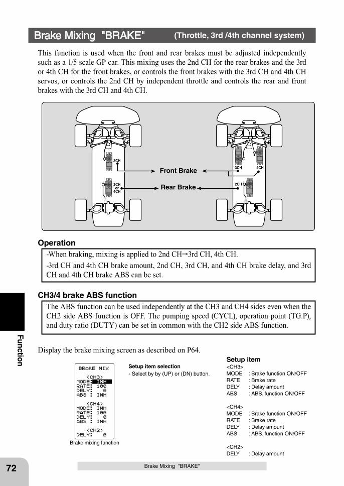
Setup item<CH3>MODE : Brake function ON/OFFRATE : Brake rateDELY : Delay amountABS : ABS. function ON/OFF
<CH4>MODE : Brake function ON/OFFRATE : Brake rateDELY : Delay amountABS : ABS. function ON/OFF
<CH2>DELY : Delay amount
Brake mixing function
72
Function
Brake Mixing "BRAKE" (Throttle, 3rd /4th channel system)
This function is used when the front and rear brakes must be adjusted independently such as a 1/5 scale GP car. This mixing uses the 2nd CH for the rear brakes and the 3rd or 4th CH for the front brakes, or controls the front brakes with the 3rd CH and 4th CH servos, or controls the 2nd CH by independent throttle and controls the rear and front brakes with the 3rd CH and 4th CH.
-When braking, mixing is applied to 2nd CH 3rd CH, 4th CH.-3rd CH and 4th CH brake amount, 2nd CH, 3rd CH, and 4th CH brake delay, and 3rd CH and 4th CH brake ABS can be set.
Operation
The ABS function can be used independently at the CH3 and CH4 sides even when the CH2 side ABS function is OFF. The pumping speed (CYCL), operation point (TG.P), and duty ratio (DUTY) can be set in common with the CH2 side ABS function.
CH3/4 brake ABS function
3CH
3CH 4CH
2CH2CHor
4CH
Front Brake
Rear Brake
Brake Mixing "BRAKE"
Display the brake mixing screen as described on P64.
Setup item selection- Select by by (UP) or (DN) button.
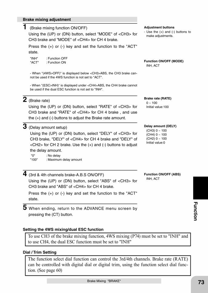
73
Function
Brake Mixing "BRAKE"
1 (Brake mixing function ON/OFF)
Using the (UP) or (DN) button, select "MODE" of <CH3> for CH3 brake and "MODE" of <CH4> for CH 4 brake.
Press the (+) or (-) key and set the function to the "ACT" state.
"INH" : Function OFF"ACT" : Function ON
- When "(4WS>OFF)" is displayed below <CH3>ABS, the CH3 brake can-not be used if the 4WS function is not set to "ACT".
- When "(ESC>INH)" is displayed under <CH4>ABS, the CH4 brake cannot be used if the dual ESC function is not set to "INH".
2 (Brake rate)
Using the (UP) or (DN) button, select "RATE" of <CH3> for CH3 brake and "RATE" of <CH4> for CH 4 brake , and use the (+) and (-) buttons to adjust the Brake rate amount.
3 (Delay amount setup)
Using the (UP) or (DN) button, select "DELY" of <CH3> for CH3 brake, "DELY" of <CH4> for CH 4 brake and "DELY" of <CH2> for CH 2 brake. Use the (+) and (-) buttons to adjust the delay amount. "0" : No delay"100" : Maximum delay amount
4 (3rd & 4th channels brake-A.B.S ON/OFF)
Using the (UP) or (DN) button, select "ABS" of <CH3> for CH3 brake and "ABS" of <CH4> for CH 4 brake.
Press the (+) or (-) key and set the function to the "ACT" state.
5 When ending, return to the ADVANCE menu screen by
pressing the (CT) button.
Brake mixing adjustment
Adjustment buttons- Use the (+) and (-) buttons to
make adjustments.
Brake rate (RATE) 0 ~ 100 Initial value:100
Delay amount (DELY) (CH3) 0 ~ 100 (CH4) 0 ~ 100 (CH2) 0 ~ 100 Initial value:0
Function ON/OFF (MODE) INH, ACT
Function ON/OFF (ABS) INH, ACT
The function select dial function can control the 3rd/4th channels. Brake rate (RATE) can be controlled with digital dial or digital trim, using the function select dial func-tion. (See page 60)
Dial / Trim Setting
To use CH3 of the brake mixing function, 4WS mixing (P74) must be set to "INH" and to use CH4, the dual ESC function must be set to "INH"
Setting the 4WS mixing/dual ESC function
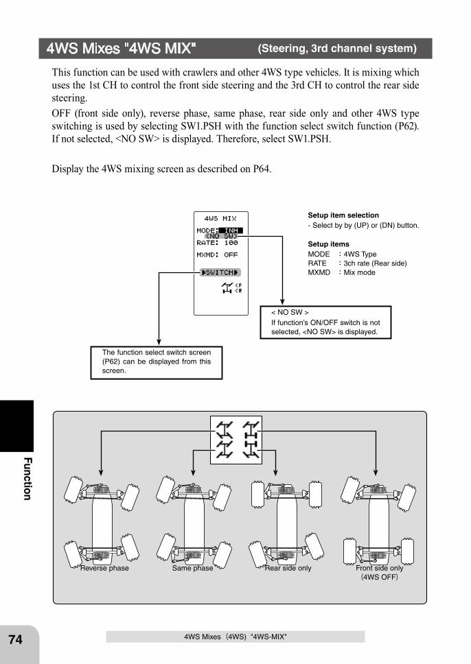
Front side only(4WS OFF)
Same phase Reverse phase Rear side only
The function select switch screen (P62) can be displayed from this screen.
< NO SW >If function’s ON/OFF switch is not selected, <NO SW> is displayed.
74
Function
4WS Mixes(4WS) "4WS-MIX"
This function can be used with crawlers and other 4WS type vehicles. It is mixing which uses the 1st CH to control the front side steering and the 3rd CH to control the rear side steering.OFF (front side only), reverse phase, same phase, rear side only and other 4WS type switching is used by selecting SW1.PSH with the function select switch function (P62). If not selected, <NO SW> is displayed. Therefore, select SW1.PSH.
Display the 4WS mixing screen as described on P64.
4WS Mixes "4WS MIX" (Steering, 3rd channel system)
Setup item selection- Select by by (UP) or (DN) button.
Setup itemsMODE :4WS TypeRATE :3ch rate (Rear side)MXMD :Mix mode
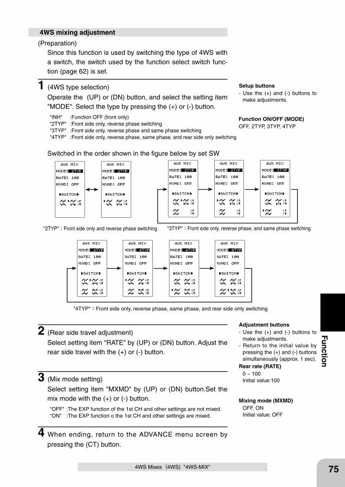
75
Function
4WS Mixes(4WS) "4WS-MIX"
(Preparation)Since this function is used by switching the type of 4WS with a switch, the switch used by the function select switch func-tion (page 62) is set.
1 (4WS type selection)
Operate the (UP) or (DN) button, and select the setting item "MODE". Select the type by pressing the (+) or (-) button.
"INH" :Function OFF (front only)"2TYP" :Front side only, reverse phase switching"3TYP" :Front side only, reverse phase and same phase switching"4TYP" :Front side only, reverse phase, same phase, and rear side only switching
4WS mixing adjustment
Switched in the order shown in the figure below by set SW
2 (Rear side travel adjustment)
Select setting item "RATE" by (UP) or (DN) button. Adjust the rear side travel with the (+) or (-) button.
3 (Mix mode setting)
Select setting item "MXMD" by (UP) or (DN) button.Set the mix mode with the (+) or (-) button.
"OFF" :The EXP function of the 1st CH and other settings are not mixed."ON" :The EXP function o the 1st CH and other settings are mixed.
4 When ending, return to the ADVANCE menu screen by
pressing the (CT) button.
Function ON/OFF (MODE)OFF, 2TYP, 3TYP, 4TYP
Mixing mode (MXMD) OFF, ON Initial value: OFF
Rear rate (RATE) 0 ~ 100 Initial value:100
"2TYP":Front side only and reverse phase switching "3TYP":Front side only, reverse phase, and same phase switching
"4TYP":Front side only, reverse phase, same phase, and rear side only switching
Setup buttons- Use the (+) and (-) buttons to
make adjustments.
Adjustment buttons- Use the (+) and (-) buttons to
make adjustments.- Return to the initial value by
pressing the (+) and (-) buttons simultaneously (approx. 1 sec).
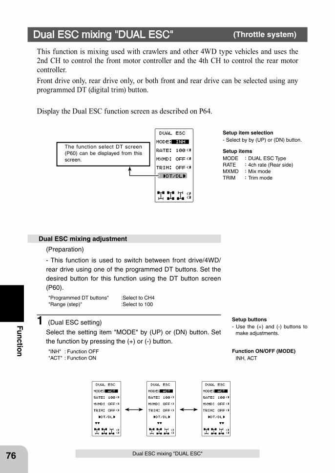
The function select DT screen (P60) can be displayed from this screen.
76
Function
Dual ESC mixing "DUAL ESC"
This function is mixing used with crawlers and other 4WD type vehicles and uses the 2nd CH to control the front motor controller and the 4th CH to control the rear motor controller.Front drive only, rear drive only, or both front and rear drive can be selected using any programmed DT (digital trim) button.
Display the Dual ESC function screen as described on P64.
Dual ESC mixing "DUAL ESC" (Throttle system)
Setup item selection- Select by by (UP) or (DN) button.
Setup itemsMODE :DUAL ESC TypeRATE :4ch rate (Rear side)MXMD :Mix modeTRIM :Trim mode
(Preparation)
- This function is used to switch between front drive/4WD/rear drive using one of the programmed DT buttons. Set the desired button for this function using the DT button screen (P60).
"Programmed DT buttons" :Select to CH4"Range (step)" :Select to 100
1 (Dual ESC setting)
Select the setting item "MODE" by (UP) or (DN) button. Set the function by pressing the (+) or (-) button.
"INH" : Function OFF"ACT" : Function ON
Dual ESC mixing adjustment
Setup buttons- Use the (+) and (-) buttons to
make adjustments.
Function ON/OFF (MODE) INH, ACT
77
Function
Dual ESC mixing "DUAL ESC"
The programmed DT button is used to select the drive type as shown in the figure below.
2 (Rear side travel adjustment)
Select the setting item "RATE" by (UP) or (DN) button. Use when applying a rotation difference to the front and rear wheels by adjusting the rear (CH4) motor controller travel with the (+) or (-) button.
3 (Mix mode setting)
Select the setting item "MXMD" by (UP) or (DN) button. Set the mix mode with the (+) or (-) button.
"OFF" : CH2 EXP function and other settings are not mixed."ON" : CH2 EXP function and other settings are mixed.
4 (Trim mode setting)
Select the setting item "TRIM" by (UP) or (DN) button. Set the trim mode with the (+) or (-) button.
"OFF" : Front side (CH2) trim data is not included."ON" : Front side (CH2) trim data is included.
5 When ending, return to the ADVANCE menu screen by
pressing the (CT) button.
The function select dial function can control the 4th channel’s ESC (Rear side) rate (RATE) with digital dial or digital trim, using the function select dial function. (See page 60)
Dial / Trim Setting
As this function drives 2 separate motor controllers simultaneously, a mutual load is applied. Use this function carefully so that the motor controllers are not damaged. Fu-taba will not be responsible for motor controller, motor, and other vehicle trouble due to use of this function.
Note:
Rear rate (RATE) 0 ~ 120 Initial value:100
Adjustment buttons- Use the (+) and (-) buttons to
make adjustments.- Return to the initial value by
pressing the (+) and (-) buttons simultaneously (approx. 1 sec).
Mixing mode (MXMD) OFF, ON Initial value: OFF
Trim mode (TRIM) OFF, ON Initial value: OFF
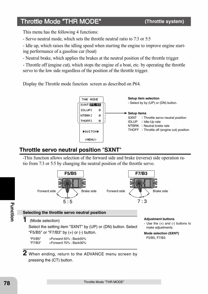
5 : 5 7 : 3
F5/B5 F7/B3
Forward side Brake side Forward side Brake side
78
Function
Throttle Mode "THR MODE"
This menu has the following 4 functions:- Servo neutral mode, which sets the throttle neutral ratio to 7:3 or 5:5- Idle up, which raises the idling speed when starting the engine to improve engine start-ing performance of a gasoline car (boat)- Neutral brake, which applies the brakes at the neutral position of the throttle trigger- Throttle off (engine cut), which stops the engine of a boat, etc. by operating the throttle servo to the low side regardless of the position of the throttle trigger.
Display the Throttle mode function screen as described on P64.
Throttle servo neutral position "SXNT"-This function allows selection of the forward side and brake (reverse) side operation ra-tio from 7:3 or 5:5 by changing the neutral position of the throttle servo.
Throttle Mode "THR MODE" (Throttle system)
Setup item selection- Select by by (UP) or (DN) button.
Setup itemsSXNT :Throttle servo neutral position IDLUP :Idle-Up rateNTBRK :Neutral brake rateTHOFF :Throttle off (engine cut) position
1 (Mode selection)
Select the setting item "SXNT" by (UP) or (DN) button. Select "F5/B5" or "F7/B3" by (+) or (-) button.
"F5/B5" =Forward 50% : Back50%"F7/B3" =Forward 70% : Back30%
2 When ending, return to the ADVANCE menu screen by
pressing the (CT) button.
Selecting the throttle servo neutral position
Mode selection (SXNT) F5/B5, F7/B3
Adjustment buttons- Use the (+) and (-) buttons to
make adjustments.
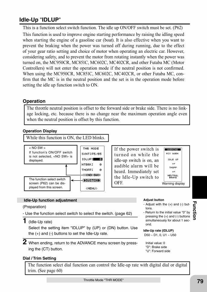
Warning displayThe function select switch screen (P62) can be dis-played from this screen.
< NO SW >If function’s ON/OFF switch is not selected, <NO SW> is displayed.
79
Function
Throttle Mode "THR MODE"
Idle-Up "IDLUP"This is a function select switch function. The idle up ON/OFF switch must be set. (P62)This function is used to improve engine starting performance by raising the idling speed when starting the engine of a gasoline car (boat). It is also effective when you want to prevent the braking when the power was turned off during running, due to the effect of your gear ratio setting and choice of motor when operating an electric car. However, considering safety, and to prevent the motor from rotating instantly when the power was turned on, the MC950CR, MC851C, MC602C, MC402CR, and other Futaba MC (Motor Controllers) will not enter the operation mode if the neutral position is not confirmed. When using the MC950CR, MC851C, MC602C, MC402CR, or other Futaba MC, con-firm that the MC is in the neutral position and the set is in the operation mode before setting the idle up function switch to ON.
The throttle neutral position is offset to the forward side or brake side. There is no link-age locking, etc. because there is no change near the maximum operation angle even when the neutral position is offset by this function.
Operation
(Preparation)
- Use the function select switch to select the switch. (page 62)
1 (Idle-Up rate)
Select the setting item "IDLUP" by (UP) or (DN) button. Use the (+) and (-) buttons to set the Idle-Up rate.
2 When ending, return to the ADVANCE menu screen by press-
ing the (CT) button.
Idle-Up function adjustment Adjust button- Adjust with the (+) and (-) but-
tons.- Return to the initial value "0" by
pressing the (+) and (-) buttons simultaneously for about 1 sec-ond.
Idle-Up rate (IDLUP) D50 ~ D1, 0, U1 ~ U50
Initial value: 0 "D": Brake side "U": Forward side
If the power switch is t u r ned on whi le the idle-up switch is on, an audible alarm will be heard. Immediately set the Idle-Up switch to OFF.
While this function is ON, the LED blinks. Operation Display
The function select dial function can control the Idle-up rate with digital dial or digital trim. (See page 60)
Dial / Trim Setting
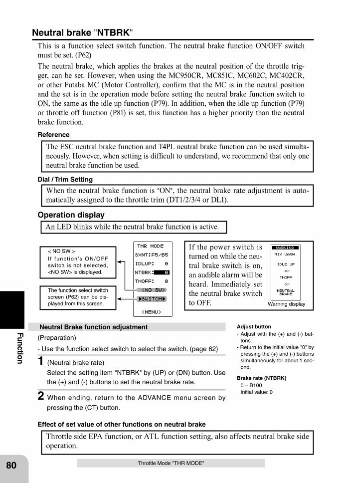
Warning display
The function select switch screen (P62) can be dis-played from this screen.
< NO SW >I f func t ion ’s ON/OFF switch is not selected, <NO SW> is displayed.
80
Function
(Preparation)
- Use the function select switch to select the switch. (page 62)
1 (Neutral brake rate)
Select the setting item "NTBRK" by (UP) or (DN) button. Use the (+) and (-) buttons to set the neutral brake rate.
2 When ending, return to the ADVANCE menu screen by
pressing the (CT) button.
Neutral Brake function adjustment
The ESC neutral brake function and T4PL neutral brake function can be used simulta-neously. However, when setting is difficult to understand, we recommend that only one neutral brake function be used.
Reference
Throttle Mode "THR MODE"
When the neutral brake function is "ON", the neutral brake rate adjustment is auto-matically assigned to the throttle trim (DT1/2/3/4 or DL1).
Dial / Trim Setting
Throttle side EPA function, or ATL function setting, also affects neutral brake side operation.
Effect of set value of other functions on neutral brake
Neutral brake "NTBRK"This is a function select switch function. The neutral brake function ON/OFF switch must be set. (P62)The neutral brake, which applies the brakes at the neutral position of the throttle trig-ger, can be set. However, when using the MC950CR, MC851C, MC602C, MC402CR, or other Futaba MC (Motor Controller), confirm that the MC is in the neutral position and the set is in the operation mode before setting the neutral brake function switch to ON, the same as the idle up function (P79). In addition, when the idle up function (P79) or throttle off function (P81) is set, this function has a higher priority than the neutral brake function.
An LED blinks while the neutral brake function is active.Operation display
If the power switch is turned on while the neu-tral brake switch is on, an audible alarm will be heard. Immediately set the neutral brake switch to OFF.
Adjust button- Adjust with the (+) and (-) but-
tons.- Return to the initial value "0" by
pressing the (+) and (-) buttons simultaneously for about 1 sec-ond.
Brake rate (NTBRK) 0 ~ B100 Initial value: 0
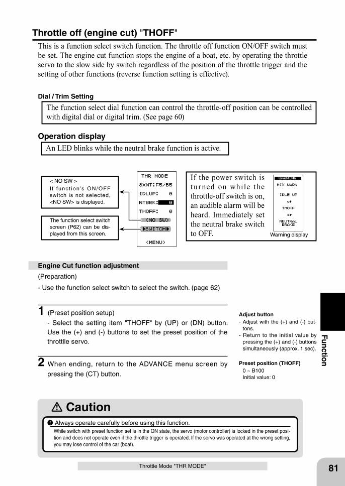
Warning display
The function select switch screen (P62) can be dis-played from this screen.
< NO SW >I f func t ion ’s ON/OFF switch is not selected, <NO SW> is displayed.
81
Function
Throttle Mode "THR MODE"
(Preparation)
- Use the function select switch to select the switch. (page 62)
1 (Preset position setup)
- Select the setting item "THOFF" by (UP) or (DN) button. Use the (+) and (-) buttons to set the preset position of the throttlle servo.
2 When ending, return to the ADVANCE menu screen by
pressing the (CT) button.
Engine Cut function adjustment
Caution Always operate carefully before using this function.While switch with preset function set is in the ON state, the servo (motor controller) is locked in the preset posi-tion and does not operate even if the throttle trigger is operated. If the servo was operated at the wrong setting, you may lose control of the car (boat).
Adjust button- Adjust with the (+) and (-) but-
tons.- Return to the initial value by
pressing the (+) and (-) buttons simultaneously (approx. 1 sec).
Preset position (THOFF) 0 ~ B100 Initial value: 0
Throttle off (engine cut) "THOFF"This is a function select switch function. The throttle off function ON/OFF switch must be set. The engine cut function stops the engine of a boat, etc. by operating the throttle servo to the slow side by switch regardless of the position of the throttle trigger and the setting of other functions (reverse function setting is effective).
An LED blinks while the neutral brake function is active.Operation display
If the power switch is t u r ned on whi le the throttle-off switch is on, an audible alarm will be heard. Immediately set the neutral brake switch to OFF.
The function select dial function can control the throttle-off position can be controlled with digital dial or digital trim. (See page 60)
Dial / Trim Setting
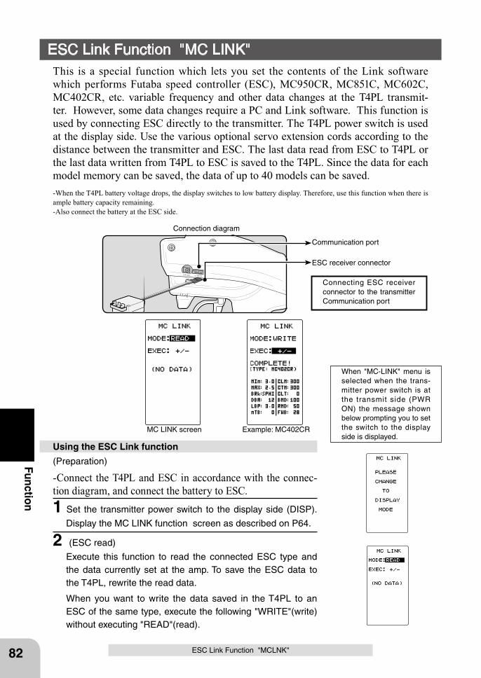
Communication port
ESC receiver connector
Connecting ESC receiver connector to the transmitter Communication port
Connection diagram
MC LINK screen Example: MC402CR
82
Function(Preparation)
-Connect the T4PL and ESC in accordance with the connec-tion diagram, and connect the battery to ESC.1 Set the transmitter power switch to the display side (DISP).
Display the MC LINK function screen as described on P64.
2 (ESC read)
Execute this function to read the connected ESC type and the data currently set at the amp. To save the ESC data to the T4PL, rewrite the read data.
When you want to write the data saved in the T4PL to an ESC of the same type, execute the following "WRITE"(write) without executing "READ"(read).
Using the ESC Link function
When "MC-LINK" menu is selected when the trans-mitter power switch is at the transmit side (PWR ON) the message shown below prompting you to set the switch to the display side is displayed.
ESC Link Function "MC LINK"This is a special function which lets you set the contents of the Link software which performs Futaba speed controller (ESC), MC950CR, MC851C, MC602C, MC402CR, etc. variable frequency and other data changes at the T4PL transmit-ter. However, some data changes require a PC and Link software. This function is used by connecting ESC directly to the transmitter. The T4PL power switch is used at the display side. Use the various optional servo extension cords according to the distance between the transmitter and ESC. The last data read from ESC to T4PL or the last data written from T4PL to ESC is saved to the T4PL. Since the data for each model memory can be saved, the data of up to 40 models can be saved.-When the T4PL battery voltage drops, the display switches to low battery display. Therefore, use this function when there is ample battery capacity remaining.-Also connect the battery at the ESC side.
ESC Link Function "MCLNK"
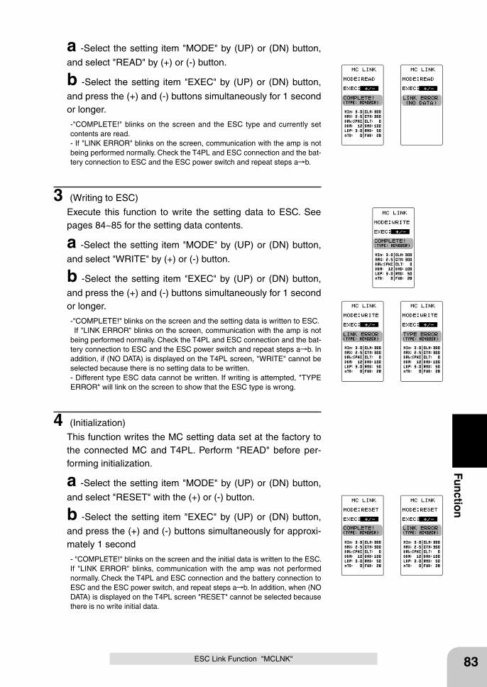
83
Function
ESC Link Function "MCLNK"
a -Select the setting item "MODE" by (UP) or (DN) button,
and select "READ" by (+) or (-) button.
b -Select the setting item "EXEC" by (UP) or (DN) button,
and press the (+) and (-) buttons simultaneously for 1 second or longer.
-"COMPLETE!" blinks on the screen and the ESC type and currently set contents are read.- If "LINK ERROR" blinks on the screen, communication with the amp is not being performed normally. Check the T4PL and ESC connection and the bat-tery connection to ESC and the ESC power switch and repeat steps a b.
3 (Writing to ESC)
Execute this function to write the setting data to ESC. See pages 84~85 for the setting data contents.
a -Select the setting item "MODE" by (UP) or (DN) button,
and select "WRITE" by (+) or (-) button.
b -Select the setting item "EXEC" by (UP) or (DN) button,
and press the (+) and (-) buttons simultaneously for 1 second or longer.
-"COMPLETE!" blinks on the screen and the setting data is written to ESC. If "LINK ERROR" blinks on the screen, communication with the amp is not being performed normally. Check the T4PL and ESC connection and the bat-tery connection to ESC and the ESC power switch and repeat steps a b. In addition, if (NO DATA) is displayed on the T4PL screen, "WRITE" cannot be selected because there is no setting data to be written.- Different type ESC data cannot be written. If writing is attempted, "TYPE ERROR" will link on the screen to show that the ESC type is wrong.
4 (Initialization)
This function writes the MC setting data set at the factory to the connected MC and T4PL. Perform "READ" before per-forming initialization.
a -Select the setting item "MODE" by (UP) or (DN) button,
and select "RESET" with the (+) or (-) button.
b -Select the setting item "EXEC" by (UP) or (DN) button,
and press the (+) and (-) buttons simultaneously for approxi-mately 1 second
- "COMPLETE!" blinks on the screen and the initial data is written to the ESC. If "LINK ERROR" blinks, communication with the amp was not performed normally. Check the T4PL and ESC connection and the battery connection to ESC and the ESC power switch, and repeat steps a b. In addition, when (NO DATA) is displayed on the T4PL screen "RESET" cannot be selected because there is no write initial data.
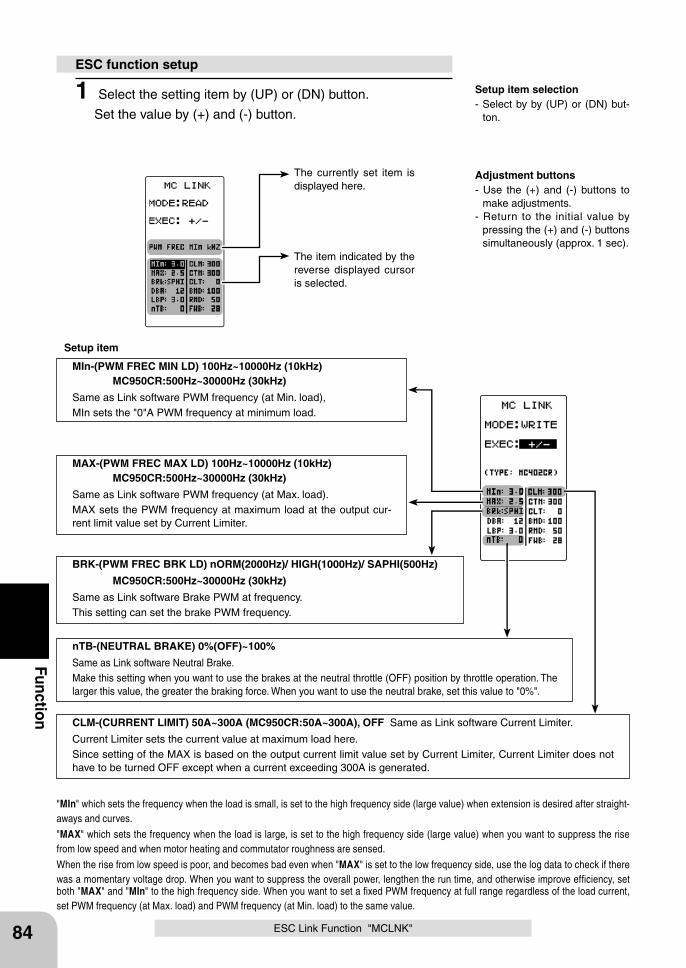
The currently set item is displayed here.
The item indicated by the reverse displayed cursor is selected.
Adjustment buttons- Use the (+) and (-) buttons to
make adjustments.- Return to the initial value by
pressing the (+) and (-) buttons simultaneously (approx. 1 sec).
Setup item selection- Select by by (UP) or (DN) but-
ton.
84
Function
MIn-(PWM FREC MIN LD) 100Hz~10000Hz (10kHz) MC950CR:500Hz~30000Hz (30kHz)
Same as Link software PWM frequency (at Min. load),MIn sets the "0"A PWM frequency at minimum load.
MAX-(PWM FREC MAX LD) 100Hz~10000Hz (10kHz) MC950CR:500Hz~30000Hz (30kHz)
Same as Link software PWM frequency (at Max. load).MAX sets the PWM frequency at maximum load at the output cur-rent limit value set by Current Limiter.
CLM-(CURRENT LIMIT) 50A~300A (MC950CR:50A~300A), OFF Same as Link software Current Limiter.
Current Limiter sets the current value at maximum load here.Since setting of the MAX is based on the output current limit value set by Current Limiter, Current Limiter does not have to be turned OFF except when a current exceeding 300A is generated.
BRK-(PWM FREC BRK LD) nORM(2000Hz)/ HIGH(1000Hz)/ SAPHI(500Hz)
MC950CR:500Hz~30000Hz (30kHz)
Same as Link software Brake PWM at frequency.This setting can set the brake PWM frequency.
"MIn" which sets the frequency when the load is small, is set to the high frequency side (large value) when extension is desired after straight-aways and curves.
"MAX" which sets the frequency when the load is large, is set to the high frequency side (large value) when you want to suppress the rise from low speed and when motor heating and commutator roughness are sensed.
When the rise from low speed is poor, and becomes bad even when "MAX" is set to the low frequency side, use the log data to check if there was a momentary voltage drop. When you want to suppress the overall power, lengthen the run time, and otherwise improve efficiency, set both "MAX" and "MIn" to the high frequency side. When you want to set a fixed PWM frequency at full range regardless of the load current, set PWM frequency (at Max. load) and PWM frequency (at Min. load) to the same value.
nTB-(NEUTRAL BRAKE) 0%(OFF)~100%
Same as Link software Neutral Brake.Make this setting when you want to use the brakes at the neutral throttle (OFF) position by throttle operation. The larger this value, the greater the braking force. When you want to use the neutral brake, set this value to "0%".
ESC function setup
Setup item
1 Select the setting item by (UP) or (DN) button.
Set the value by (+) and (-) button.
ESC Link Function "MCLNK"
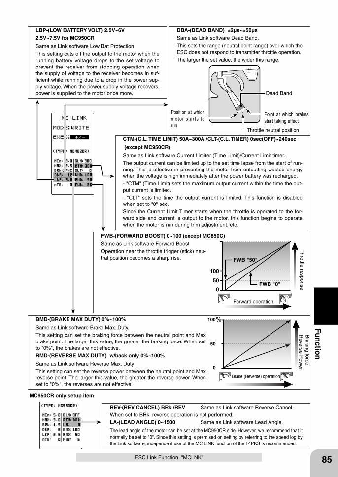
85
Function
Throttle neutral position
Dead Band
Point at which brakes start taking effect
Position at which motor s tar ts to run
DBA-(DEAD BAND) ±2μs~±50μs
Same as Link software Dead Band.This sets the range (neutral point range) over which the ESC does not respond to transmitter throttle operation.The larger the set value, the wider this range.
LBP-(LOW BATTERY VOLT) 2.5V~6V
2.5V~7.5V for MC950CR
Same as Link software Low Bat ProtectionThis setting cuts off the output to the motor when the running battery voltage drops to the set voltage to prevent the receiver from stopping operation when the supply of voltage to the receiver becomes in suf-ficient while running due to a drop in the power sup-ply voltage. When the power supply voltage recovers, power is supplied to the motor once more.
CTM-(C.L. TIME LIMIT) 50A~300A /CLT-(C.L. TIMER) 0sec(OFF)~240sec
(except MC950CR)
Same as Link software Current Limiter (Time Limit)/Current Limit timer.The output current can be limited up to the set time lapse from the start of run-ning. This is effective in preventing the motor from outputting wasted energy when the voltage is high immediately after the power battery was recharged.- "CTM" (Time Limit) sets the maximum output current within the time the out-put current is limited.- "CLT" sets the time the output current is limited. This function is disabled when set to "0" sec.Since the Current Limit Timer starts when the throttle is operated to the for-ward side and current is output to the motor, this function begins to operate when the motor is run during trim adjustment, etc.
100
50
0
%
Brake (Reverse) operation
Braking force
Reverse P
ower
BMD-(BRAKE MAX DUTY) 0%~100%
Same as Link software Brake Max. Duty.This setting can set the braking force between the neutral point and Max brake point. The larger this value, the greater the braking force. When set to "0%", the brakes are not effective.RMD-(REVERSE MAX DUTY) w/back only 0%~100%
Same as Link software Reverse Max. DutyThis setting can set the reverse power between the neutral point and Max reverse point. The larger this value, the greater the reverse power. When set to "0%", the reverses are not effective.
100
50
0
Forward operation
Throttle response
FWB "50"
FWB "0"
FWB-(FORWARD BOOST) 0~100 (except MC850C)
Same as Link software Forward BoostOperation near the throttle trigger (stick) neu-tral position becomes a sharp rise.
MC950CR only setup item
REV-(REV CANCEL) BRk /REV Same as Link software Reverse Cancel.When set to BRk, reverse operation is not performed.LA-(LEAD ANGLE) 0~1500 Same as Link software Lead Angle.
The lead angle of the motor can be set at the MC950CR side. However, we recommend that it normally be set to "0". Since this setting is premised on setting by referring to the speed log by the Link software, independent use of the MC LINK function of the T4PKS is recommended.
ESC Link Function "MCLNK"
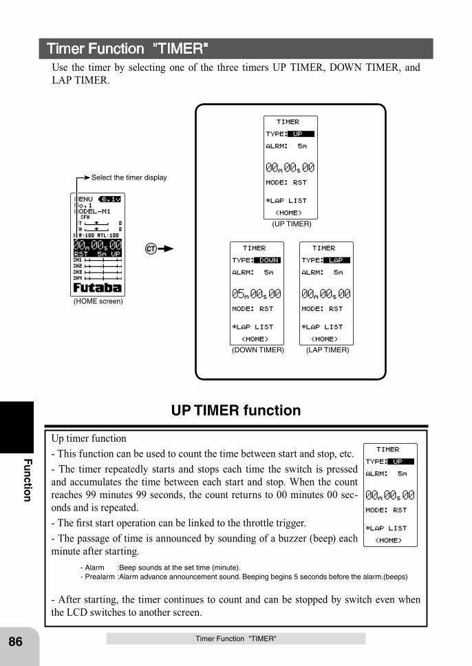
86
Function
Timer Function "TIMER"Use the timer by selecting one of the three timers UP TIMER, DOWN TIMER, and LAP TIMER.
UP TIMER function
Up timer function- This function can be used to count the time between start and stop, etc.- The timer repeatedly starts and stops each time the switch is pressed and accumulates the time between each start and stop. When the count reaches 99 minutes 99 seconds, the count returns to 00 minutes 00 sec-onds and is repeated.- The first start operation can be linked to the throttle trigger.- The passage of time is announced by sounding of a buzzer (beep) each minute after starting.
- Alarm :Beep sounds at the set time (minute).- Prealarm :Alarm advance announcement sound. Beeping begins 5 seconds before the alarm.(beeps)
- After starting, the timer continues to count and can be stopped by switch even when the LCD switches to another screen.
Timer Function "TIMER"
CT
(HOME screen)
(UP TIMER)
(DOWN TIMER) (LAP TIMER)
Select the timer display
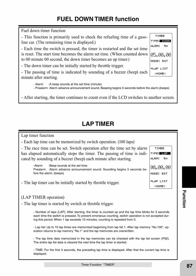
87
Function
FUEL DOWN TIMER function
Fuel down timer function- This function is primarily used to check the refueling time of a gaso-line car. (The remaining time is displayed.)- Each time the switch is pressed, the timer is restarted and the set time is reset. The start time becomes the alarm set time. (When counted down to 00 minute 00 second, the down timer becomes an up timer.)- The down timer can be initially started by throttle trigger.- The passing of time is indicated by sounding of a buzzer (beep) each minute after starting.
- Alarm :A beep sounds at the set time (minute).- Prealarm :Alarm advance announcement sound. Beeping begins 5 seconds before the alarm.(beeps)
- After starting, the timer continues to count even if the LCD switches to another screen.
Timer Function "TIMER"
LAP TIMER
Lap timer function- Each lap time can be memorized by switch operation. (100 laps)- The race time can be set. Switch operation after the time set by alarm has elapsed automatically stops the timer. The passing of time is indi-cated by sounding of a buzzer (beep) each minute after starting.
-Alarm :Beep sounds at the set time.Prealarm :Alarm advance announcement sound. Sounding begins 5 seconds be-fore the alarm. (beeps)
- The lap timer can be initially started by throttle trigger.
(LAP TIMER operation)- The lap timer is started by switch or throttle trigger.
- Number of laps (LAP): After starting, the timer is counted up and the lap time blinks for 3 seconds each time the switch is pressed. To prevent erroneous counting, switch operation is not accepted dur-ing this period. When 1 lap exceeds 10 minutes, counting is repeated from 0.
- Lap list: Up to 10 lap times are memorized beginning from lap list 1. After lap memory "No.100", op-eration returns to lap memory "No.1" and the lap memories are overwritten.
- The lap time data memorized in the lap memories can be checked with the lap list screen (P92). The entire lap list data is cleared the next time the lap timer is started.
- TIME: For the first 3 seconds, the preceding lap time is displayed. After that the current lap time is displayed.
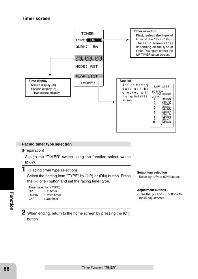
88
Function
Timer selection First, select the type of
timer at the "TYPE" item. The setup screen varies depending on the type of timer. This figure shows the UP TIMER setup screen.
Lap list The lap memory
d a t a c a n b e c h e c k e d w i t h the lap list (P92) screen.
Timer Function "TIMER"
(Preparation)
Assign the "TIMER" switch using the function select switch (p.62).
1 (Racing timer type selection)
Select the setting item "TYPE" by (UP) or (DN) button. Press the (+) or (-) button and set the racing timer type.
Timer selection (TYPE)UP : Up timerDOWN : Down timerLAP : Lap timer
2 When ending, return to the home screen by pressing the (CT)
button.
Racing timer type selection
Time display Minute display (m) Second display (s) 1/100 second display
Setup item selection- Select by (UP) or (DN) button.
Adjustment buttons- Use the (+) and (-) buttons to
make adjustments.
Timer screen
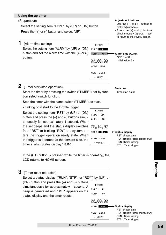
Alarm time (ALRM) OFF, 1 ~ 99 m Initial value: 5 m
Status display RST :Reset state RDY :Throttle trigger operation wait RUN :Timer running STP : Timer stopped
Status display RST :Reset state RDY :Throttle trigger operation wait RUN :Timer running STP : Timer stopped
89
Function
Timer Function "TIMER"
(Preparation)
Select the setting item "TYPE" by (UP) or (DN) button.
Press the (+) or (-) button and select "UP".
1 (Alarm time setting)
Select the setting item "ALRM" by (UP) or (DN) button and set the alarm time with the (+) or (-) button.
2 (Timer start/stop operation)
Start the timer by pressing the switch ("TIMER") set by func-tion select switch function.
Stop the timer with the same switch ("TIMER") as start.
- Linking only start to the throttle trigger
Select the setting item "RST" by (UP) or (DN) button and press the (+) and (-) buttons simul-taneously for approximately 1 second. When the set beeps and the status display switches from "RST" to blinking "RDY", the system en-ters the trigger operation ready state. When the trigger is operated at the forward side, the timer starts. (Status display "RUN")
If the (CT) button is pressed while the timer is operating, the LCD returns to HOME screen.
3 (Timer reset operation)
Select a status display ("RUN", "STP", or "RDY") by (UP) or (DN) button and press the (+) and (-) buttons simultaneously for approximately 1 second. A beep is generated and "RST" appears on the status display and the timer resets.
Using the up timerAdjustment buttons- Use the (+) and (-) buttons to
make adjustments.- Press the (+) and (-) buttons
simultaneously (approx. 1 sec) to return to the HOME screen.
Switches Time start / stop
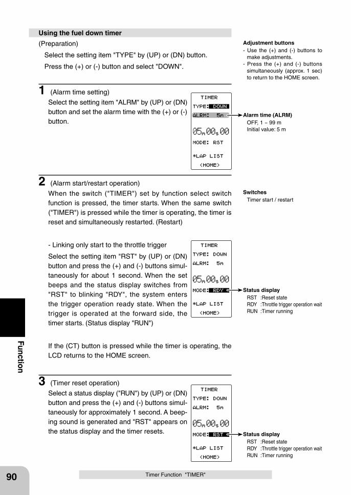
Alarm time (ALRM) OFF, 1 ~ 99 m Initial value: 5 m
Status display RST :Reset state RDY :Throttle trigger operation wait RUN :Timer running
Status display RST :Reset state RDY :Throttle trigger operation wait RUN :Timer running
90
Function
Timer Function "TIMER"
(Preparation)
Select the setting item "TYPE" by (UP) or (DN) button.
Press the (+) or (-) button and select "DOWN".
1 (Alarm time setting)
Select the setting item "ALRM" by (UP) or (DN) button and set the alarm time with the (+) or (-) button.
2 (Alarm start/restart operation)
When the switch ("TIMER") set by function select switch function is pressed, the timer starts. When the same switch ("TIMER") is pressed while the timer is operating, the timer is reset and simultaneously restarted. (Restart)
- Linking only start to the throttle trigger
Select the setting item "RST" by (UP) or (DN) button and press the (+) and (-) buttons simul-taneously for about 1 second. When the set beeps and the status display switches from "RST" to blinking "RDY", the system enters the trigger operation ready state. When the trigger is operated at the forward side, the timer starts. (Status display "RUN")
If the (CT) button is pressed while the timer is operating, the LCD returns to the HOME screen.
3 (Timer reset operation)
Select a status display ("RUN") by (UP) or (DN) button and press the (+) and (-) buttons simul-taneously for approximately 1 second. A beep-ing sound is generated and "RST" appears on the status display and the timer resets.
Using the fuel down timerAdjustment buttons- Use the (+) and (-) buttons to
make adjustments.- Press the (+) and (-) buttons
simultaneously (approx. 1 sec) to return to the HOME screen.
Switches Timer start / restart
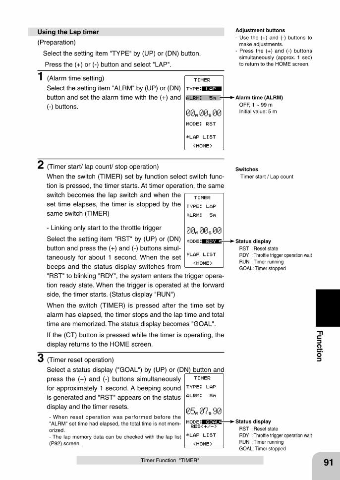
Status display RST :Reset state RDY :Throttle trigger operation wait RUN :Timer running GOAL: Timer stopped
Status display RST :Reset state RDY :Throttle trigger operation wait RUN :Timer running GOAL: Timer stopped
Alarm time (ALRM) OFF, 1 ~ 99 m Initial value: 5 m
91
Function
Timer Function "TIMER"
(Preparation)
Select the setting item "TYPE" by (UP) or (DN) button.
Press the (+) or (-) button and select "LAP".
1 (Alarm time setting)
Select the setting item "ALRM" by (UP) or (DN) button and set the alarm time with the (+) and (-) buttons.
2 (Timer start/ lap count/ stop operation)
When the switch (TIMER) set by function select switch func-tion is pressed, the timer starts. At timer operation, the same switch becomes the lap switch and when the set time elapses, the timer is stopped by the same switch (TIMER)
- Linking only start to the throttle trigger
Select the setting item "RST" by (UP) or (DN) button and press the (+) and (-) buttons simul-taneously for about 1 second. When the set beeps and the status display switches from "RST" to blinking "RDY", the system enters the trigger opera-tion ready state. When the trigger is operated at the forward side, the timer starts. (Status display "RUN")
When the switch (TIMER) is pressed after the time set by alarm has elapsed, the timer stops and the lap time and total time are memorized. The status display becomes "GOAL".
If the (CT) button is pressed while the timer is operating, the display returns to the HOME screen.
3 (Timer reset operation)
Select a status display ("GOAL") by (UP) or (DN) button and press the (+) and (-) buttons simultaneously for approximately 1 second. A beeping sound is generated and "RST" appears on the status display and the timer resets.
- When reset operation was performed before the "ALRM" set time had elapsed, the total time is not mem-orized.- The lap memory data can be checked with the lap list (P92) screen.
Using the Lap timer Adjustment buttons- Use the (+) and (-) buttons to
make adjustments.- Press the (+) and (-) buttons
simultaneously (approx. 1 sec) to return to the HOME screen.
Switches Timer start / Lap count
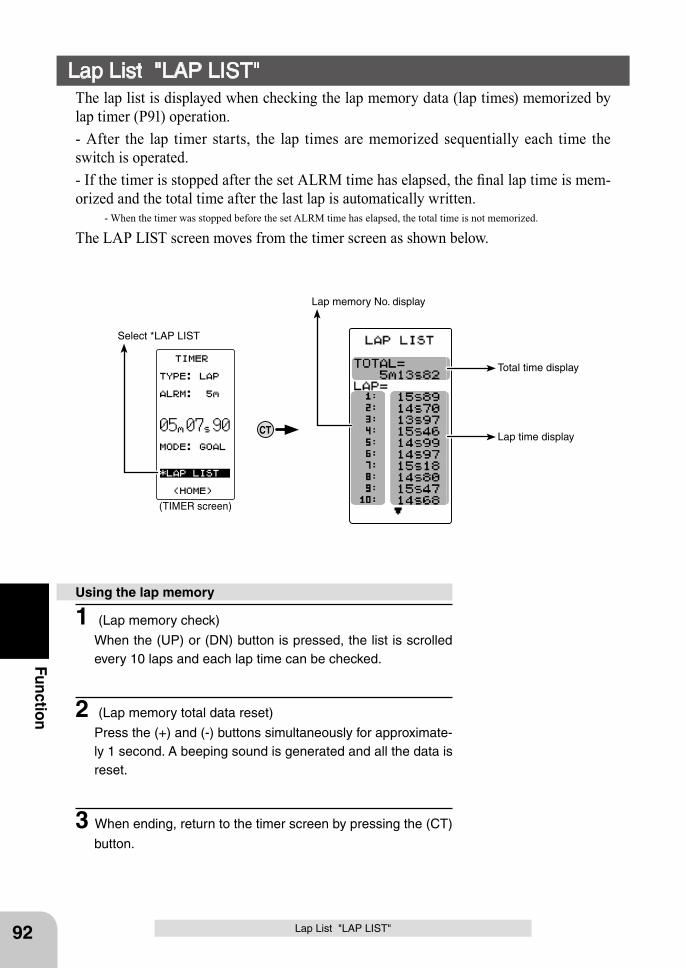
Lap time display
Total time display
Lap memory No. display
CT
(TIMER screen)
Select *LAP LIST
92
Function
Lap List "LAP LIST"
Lap List "LAP LIST"The lap list is displayed when checking the lap memory data (lap times) memorized by lap timer (P91) operation.- After the lap timer starts, the lap times are memorized sequentially each time the switch is operated.- If the timer is stopped after the set ALRM time has elapsed, the final lap time is mem-orized and the total time after the last lap is automatically written. - When the timer was stopped before the set ALRM time has elapsed, the total time is not memorized.
The LAP LIST screen moves from the timer screen as shown below.
1 (Lap memory check)
When the (UP) or (DN) button is pressed, the list is scrolled every 10 laps and each lap time can be checked.
2 (Lap memory total data reset)
Press the (+) and (-) buttons simultaneously for approximate-ly 1 second. A beeping sound is generated and all the data is reset.
3 When ending, return to the timer screen by pressing the (CT)
button.
Using the lap memory
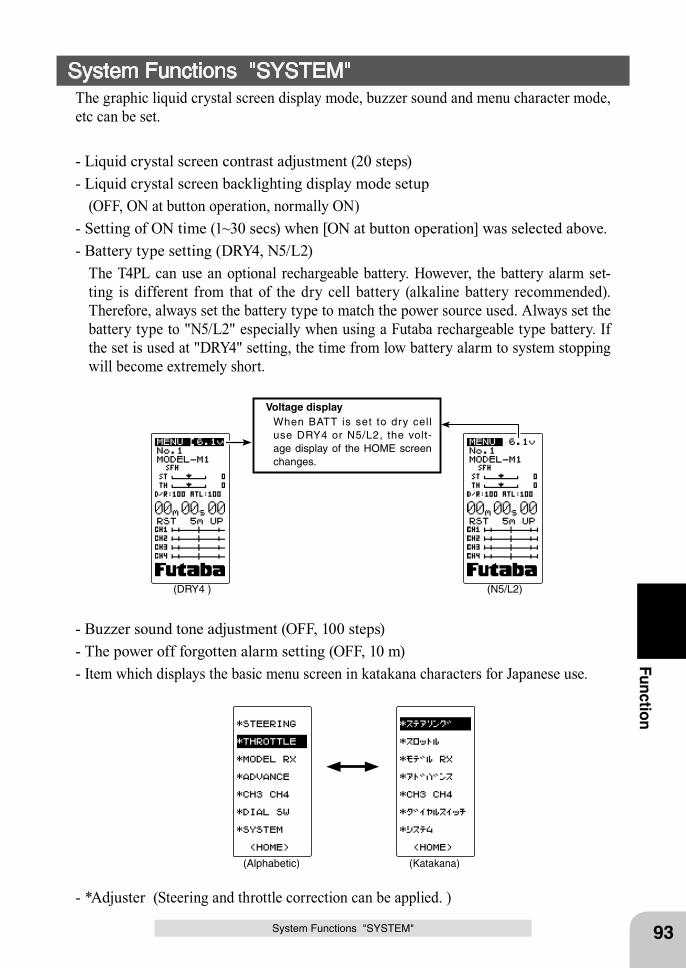
(DRY4 ) (N5/L2)
Voltage display When BATT is set to dry cell
use DRY4 or N5/L2, the volt-age display of the HOME screen changes.
(Katakana)(Alphabetic)
93
Function
System Functions "SYSTEM"
System Functions "SYSTEM"The graphic liquid crystal screen display mode, buzzer sound and menu character mode, etc can be set.
- Liquid crystal screen contrast adjustment (20 steps)- Liquid crystal screen backlighting display mode setup (OFF, ON at button operation, normally ON)- Setting of ON time (1~30 secs) when [ON at button operation] was selected above.- Battery type setting (DRY4, N5/L2) The T4PL can use an optional rechargeable battery. However, the battery alarm set-
ting is different from that of the dry cell battery (alkaline battery recommended). Therefore, always set the battery type to match the power source used. Always set the battery type to "N5/L2" especially when using a Futaba rechargeable type battery. If the set is used at "DRY4" setting, the time from low battery alarm to system stopping will become extremely short.
- Buzzer sound tone adjustment (OFF, 100 steps)- The power off forgotten alarm setting (OFF, 10 m)- Item which displays the basic menu screen in katakana characters for Japanese use.
- *Adjuster (Steering and throttle correction can be applied. )
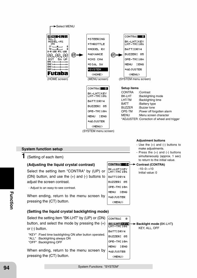
Contrast (CONTRA) -10~0~+10 Initial value: 0
Backlight mode (BK-LHT) KEY, ALL, OFF
94
Function
1 (Setting of each item)
(Adjusting the liquid crystal contrast)
Select the setting item "CONTRA" by (UP) or (DN) button, and use the (+) and (-) buttons to adjust the screen contrast.
- Adjust to an easy-to-see contrast.
When ending, return to the menu screen by pressing the (CT) button.
(Setting the liquid crystal backlighting mode)
Select the setting item "BK-LHT" by (UP) or (DN) button, and select the mode by pressing the (+) or (-) button.
"KEY" :Fixed time backlighting ON after button operated."ALL" :Backlighting always ON"OFF" :Backlighting OFF
When ending, return to the menu screen by pressing the (CT) button.
System function setup
Setup itemsCONTRA :ContrastBK-LHT :Backlighting modeLHT-TM :Backlighting timeBATT :Battery typeBUZZER :Buzzer toneOPE-TM :Power off forgotten alarmMENU :Menu screen character *ADJUSTER :Correction of wheel and trigger
Adjustment buttons- Use the (+) and (-) buttons to
make adjustments.- Press the (+) and (-) buttons
simultaneously (approx. 1 sec) to return to the initial value.
System Functions "SYSTEM"
CTCT
(HOME screen) (MENU screen) (SYSTEM menu screen)
(SYSTEM menu screen)
Select MENU
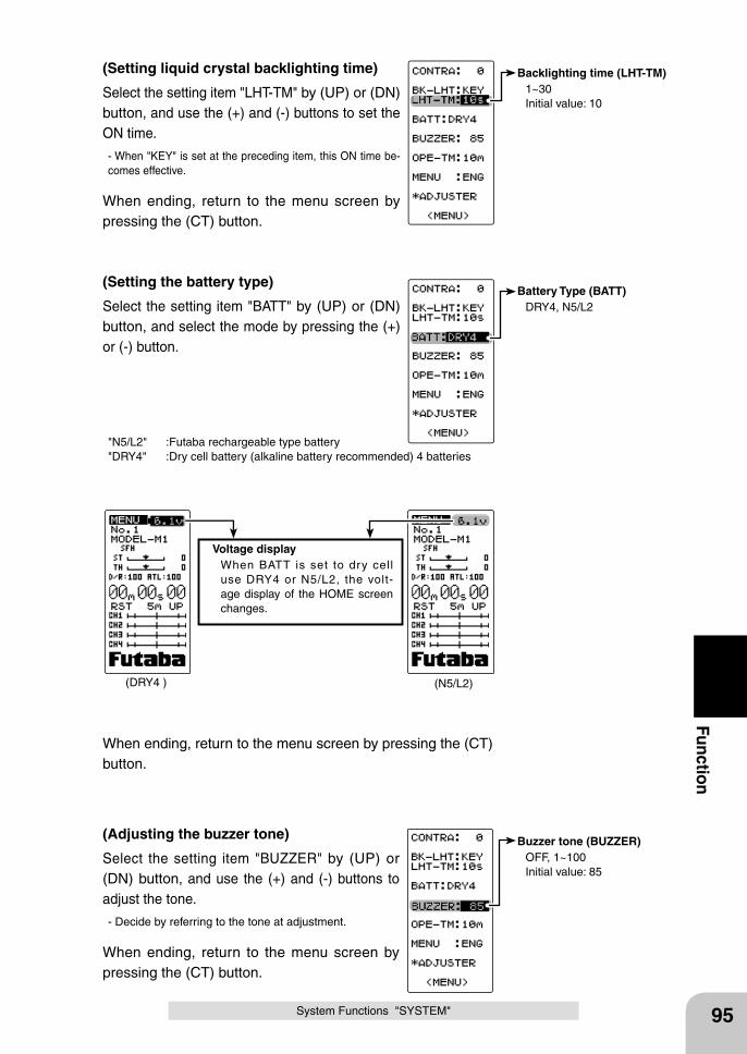
Backlighting time (LHT-TM) 1~30 Initial value: 10
Battery Type (BATT) DRY4, N5/L2
Buzzer tone (BUZZER) OFF, 1~100 Initial value: 85
(DRY4 ) (N5/L2)
Voltage display When BATT is set to dry cell
use DRY4 or N5/L2, the volt-age display of the HOME screen changes.
95
Function(Setting liquid crystal backlighting time)
Select the setting item "LHT-TM" by (UP) or (DN) button, and use the (+) and (-) buttons to set the ON time.
- When "KEY" is set at the preceding item, this ON time be-comes effective.
When ending, return to the menu screen by pressing the (CT) button.
(Setting the battery type)
Select the setting item "BATT" by (UP) or (DN) button, and select the mode by pressing the (+) or (-) button.
"N5/L2" :Futaba rechargeable type battery"DRY4" :Dry cell battery (alkaline battery recommended) 4 batteries
System Functions "SYSTEM"
When ending, return to the menu screen by pressing the (CT) button.
(Adjusting the buzzer tone)
Select the setting item "BUZZER" by (UP) or (DN) button, and use the (+) and (-) buttons to adjust the tone.
- Decide by referring to the tone at adjustment.
When ending, return to the menu screen by pressing the (CT) button.
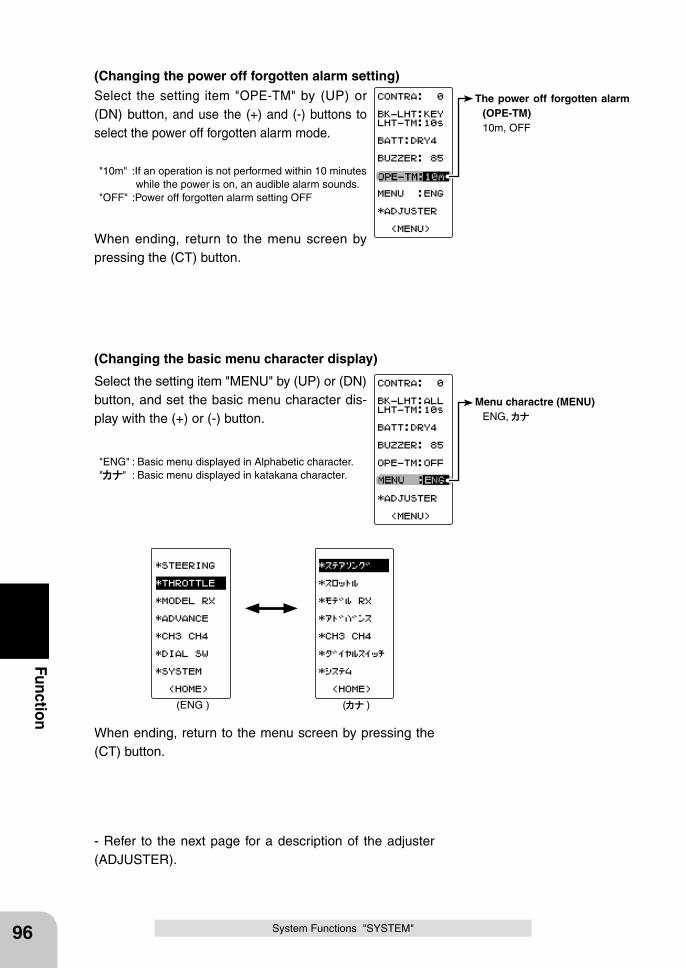
The power off forgotten alarm (OPE-TM)
10m, OFF
(ENG ) ( )
Menu charactre (MENU) ENG,
96
Function
System Functions "SYSTEM"
(Changing the power off forgotten alarm setting)Select the setting item "OPE-TM" by (UP) or (DN) button, and use the (+) and (-) buttons to select the power off forgotten alarm mode.
"10m" :If an operation is not performed within 10 minutes while the power is on, an audible alarm sounds.
"OFF" :Power off forgotten alarm setting OFF
When ending, return to the menu screen by pressing the (CT) button.
(Changing the basic menu character display)
Select the setting item "MENU" by (UP) or (DN) button, and set the basic menu character dis-play with the (+) or (-) button.
"ENG" : Basic menu displayed in Alphabetic character." " : Basic menu displayed in katakana character.
When ending, return to the menu screen by pressing the (CT) button.
- Refer to the next page for a description of the adjuster (ADJUSTER).
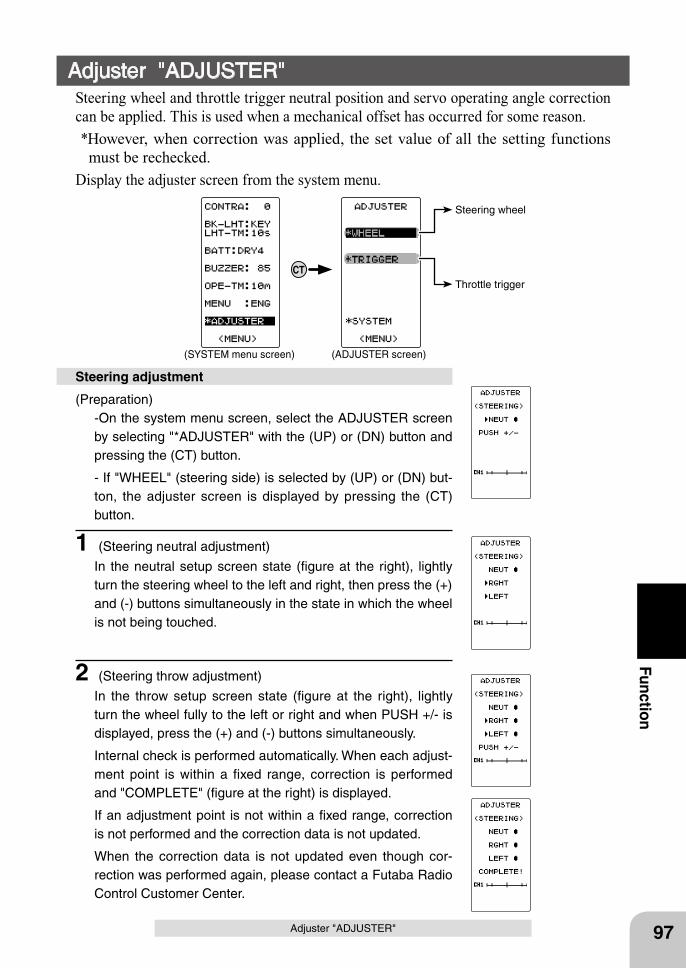
97
Function
Adjuster "ADJUSTER"
(Preparation)-On the system menu screen, select the ADJUSTER screen by selecting "*ADJUSTER" with the (UP) or (DN) button and pressing the (CT) button.
- If "WHEEL" (steering side) is selected by (UP) or (DN) but-ton, the adjuster screen is displayed by pressing the (CT) button.
1 (Steering neutral adjustment)
In the neutral setup screen state (figure at the right), lightly turn the steering wheel to the left and right, then press the (+) and (-) buttons simultaneously in the state in which the wheel is not being touched.
2 (Steering throw adjustment)
In the throw setup screen state (figure at the right), lightly turn the wheel fully to the left or right and when PUSH +/- is displayed, press the (+) and (-) buttons simultaneously.
Internal check is performed automatically. When each adjust-ment point is within a fixed range, correction is performed and "COMPLETE" (figure at the right) is displayed.
If an adjustment point is not within a fixed range, correction is not performed and the correction data is not updated.
When the correction data is not updated even though cor-rection was performed again, please contact a Futaba Radio Control Customer Center.
Steering adjustment
Adjuster "ADJUSTER"Steering wheel and throttle trigger neutral position and servo operating angle correction can be applied. This is used when a mechanical offset has occurred for some reason. *However, when correction was applied, the set value of all the setting functions
must be rechecked.Display the adjuster screen from the system menu.
Throttle trigger
Steering wheel
CT
(SYSTEM menu screen) (ADJUSTER screen)
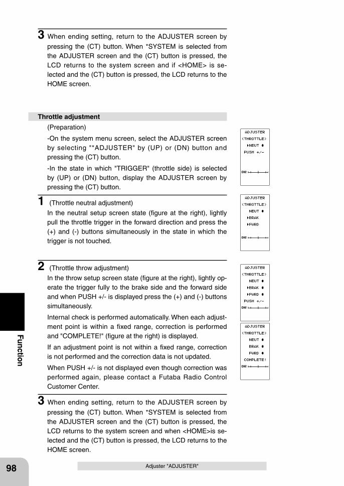
98
Function
Adjuster "ADJUSTER"
3 When ending setting, return to the ADJUSTER screen by
pressing the (CT) button. When *SYSTEM is selected from the ADJUSTER screen and the (CT) button is pressed, the LCD returns to the system screen and if <HOME> is se-lected and the (CT) button is pressed, the LCD returns to the HOME screen.
(Preparation)
-On the system menu screen, select the ADJUSTER screen by selecting "*ADJUSTER" by (UP) or (DN) button and pressing the (CT) button.
-In the state in which "TRIGGER" (throttle side) is selected by (UP) or (DN) button, display the ADJUSTER screen by pressing the (CT) button.
1 (Throttle neutral adjustment)
In the neutral setup screen state (figure at the right), lightly pull the throttle trigger in the forward direction and press the (+) and (-) buttons simultaneously in the state in which the trigger is not touched.
2 (Throttle throw adjustment)
In the throw setup screen state (figure at the right), lightly op-erate the trigger fully to the brake side and the forward side and when PUSH +/- is displayed press the (+) and (-) buttons simultaneously.
Internal check is performed automatically. When each adjust-ment point is within a fixed range, correction is performed and "COMPLETE!" (figure at the right) is displayed.
If an adjustment point is not within a fixed range, correction is not performed and the correction data is not updated.
When PUSH +/- is not displayed even though correction was performed again, please contact a Futaba Radio Control Customer Center.
3 When ending setting, return to the ADJUSTER screen by
pressing the (CT) button. When *SYSTEM is selected from the ADJUSTER screen and the (CT) button is pressed, the LCD returns to the system screen and when <HOME>is se-lected and the (CT) button is pressed, the LCD returns to the HOME screen.
Throttle adjustment
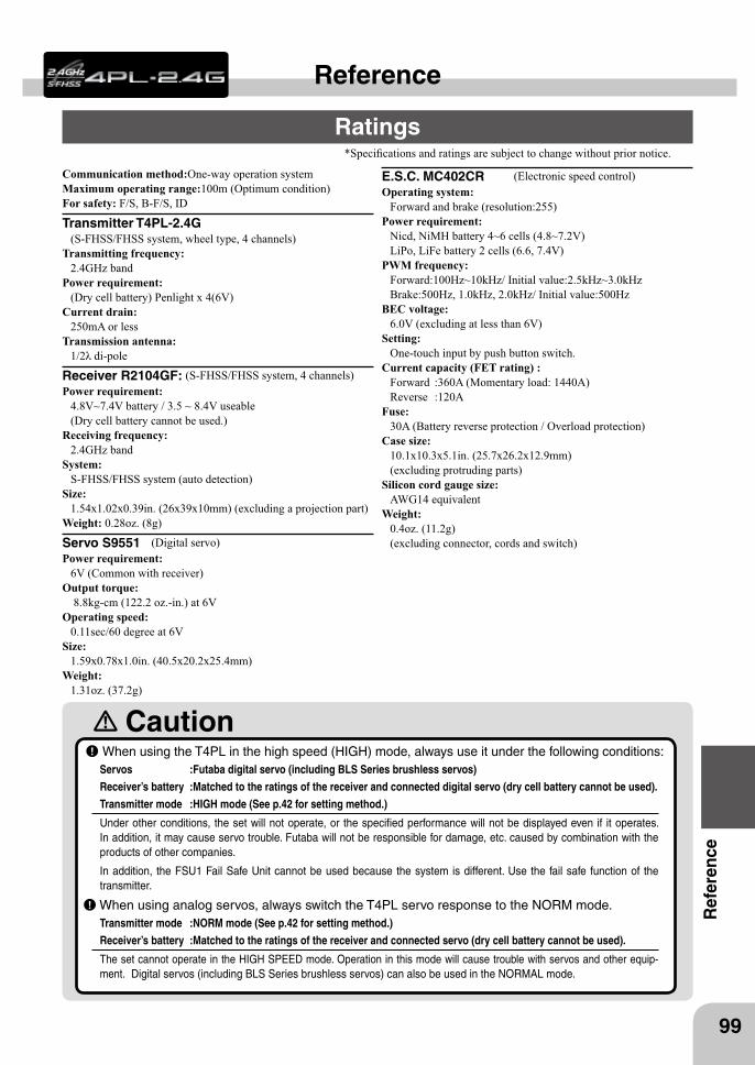
99
Ref
eren
ce
Reference
Ratings*Specifications and ratings are subject to change without prior notice.
Caution When using the T4PL in the high speed (HIGH) mode, always use it under the following conditions:Servos :Futaba digital servo (including BLS Series brushless servos) Receiver’s battery :Matched to the ratings of the receiver and connected digital servo (dry cell battery cannot be used).Transmitter mode :HIGH mode (See p.42 for setting method.)
Under other conditions, the set will not operate, or the specified performance will not be displayed even if it operates. In addition, it may cause servo trouble. Futaba will not be responsible for damage, etc. caused by combination with the products of other companies.
In addition, the FSU1 Fail Safe Unit cannot be used because the system is different. Use the fail safe function of the transmitter.
When using analog servos, always switch the T4PL servo response to the NORM mode.Transmitter mode :NORM mode (See p.42 for setting method.)Receiver’s battery :Matched to the ratings of the receiver and connected servo (dry cell battery cannot be used).
The set cannot operate in the HIGH SPEED mode. Operation in this mode will cause trouble with servos and other equip-ment. Digital servos (including BLS Series brushless servos) can also be used in the NORMAL mode.
Communication method:One-way operation systemMaximum operating range:100m (Optimum condition)For safety: F/S, B-F/S, ID
Transmitter T4PL-2.4G(S-FHSS/FHSS system, wheel type, 4 channels)
Transmitting frequency: 2.4GHz band
Power requirement: (Dry cell battery) Penlight x 4(6V)
Current drain: 250mA or less
Transmission antenna: 1/2λ di-pole
Receiver R2104GF: (S-FHSS/FHSS system, 4 channels)Power requirement:
4.8V~7.4V battery / 3.5 ~ 8.4V useable (Dry cell battery cannot be used.)
Receiving frequency: 2.4GHz band
System: S-FHSS/FHSS system (auto detection)
Size: 1.54x1.02x0.39in. (26x39x10mm) (excluding a projection part)
Weight: 0.28oz. (8g)
Servo S9551 (Digital servo) Power requirement:
6V (Common with receiver) Output torque:
8.8kg-cm (122.2 oz.-in.) at 6V Operating speed:
0.11sec/60 degree at 6VSize:
1.59x0.78x1.0in. (40.5x20.2x25.4mm)Weight:
1.31oz. (37.2g)
E.S.C. MC402CR (Electronic speed control) Operating system:
Forward and brake (resolution:255)Power requirement:
Nicd, NiMH battery 4~6 cells (4.8~7.2V) LiPo, LiFe battery 2 cells (6.6, 7.4V)
PWM frequency: Forward:100Hz~10kHz/ Initial value:2.5kHz~3.0kHzBrake:500Hz, 1.0kHz, 2.0kHz/ Initial value:500Hz
BEC voltage: 6.0V (excluding at less than 6V)
Setting: One-touch input by push button switch.
Current capacity (FET rating) :Forward :360A (Momentary load: 1440A)Reverse :120A
Fuse: 30A (Battery reverse protection / Overload protection)
Case size: 10.1x10.3x5.1in. (25.7x26.2x12.9mm) (excluding protruding parts)
Silicon cord gauge size: AWG14 equivalent
Weight: 0.4oz. (11.2g) (excluding connector, cords and switch)
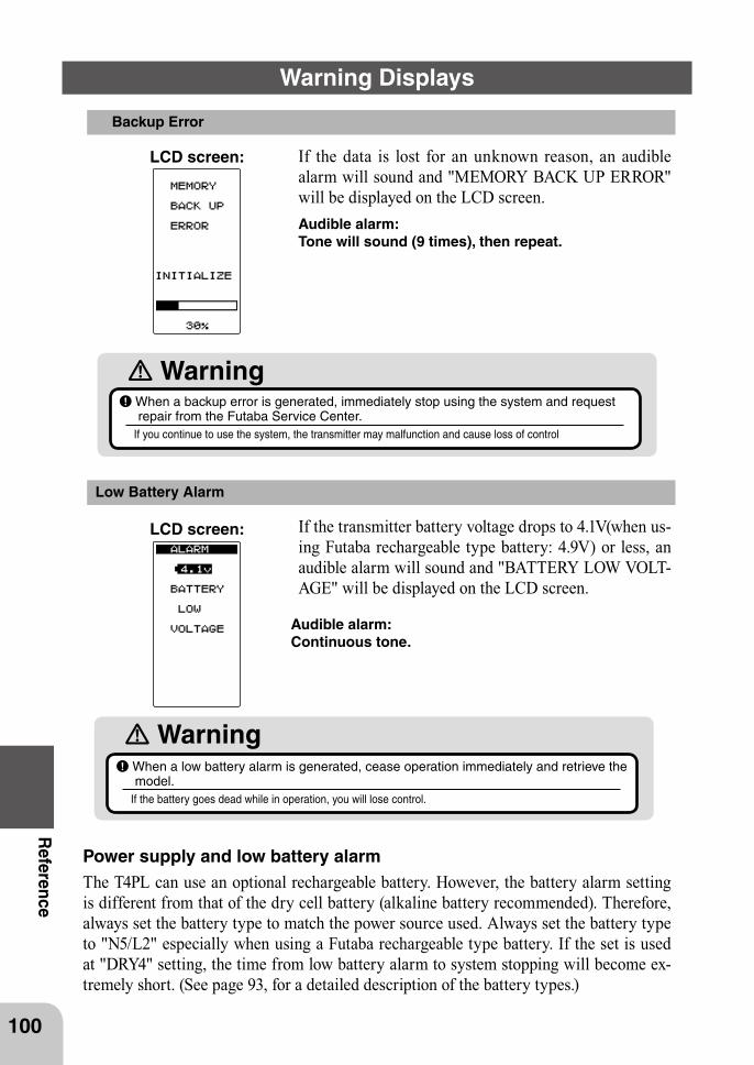
100
Reference
Warning Displays
Low Battery Alarm
If the transmitter battery voltage drops to 4.1V(when us-ing Futaba rechargeable type battery: 4.9V) or less, an audible alarm will sound and "BATTERY LOW VOLT-AGE" will be displayed on the LCD screen.
LCD screen:
Audible alarm: Continuous tone.
WarningWhen a low battery alarm is generated, cease operation immediately and retrieve the model.
If the battery goes dead while in operation, you will lose control.
Power supply and low battery alarmThe T4PL can use an optional rechargeable battery. However, the battery alarm setting is different from that of the dry cell battery (alkaline battery recommended). Therefore, always set the battery type to match the power source used. Always set the battery type to "N5/L2" especially when using a Futaba rechargeable type battery. If the set is used at "DRY4" setting, the time from low battery alarm to system stopping will become ex-tremely short. (See page 93, for a detailed description of the battery types.)
Backup Error
If the data is lost for an unknown reason, an audible alarm will sound and "MEMORY BACK UP ERROR" will be displayed on the LCD screen.
LCD screen:
Audible alarm: Tone will sound (9 times), then repeat.
Warning When a backup error is generated, immediately stop using the system and request repair from the Futaba Service Center.
If you continue to use the system, the transmitter may malfunction and cause loss of control
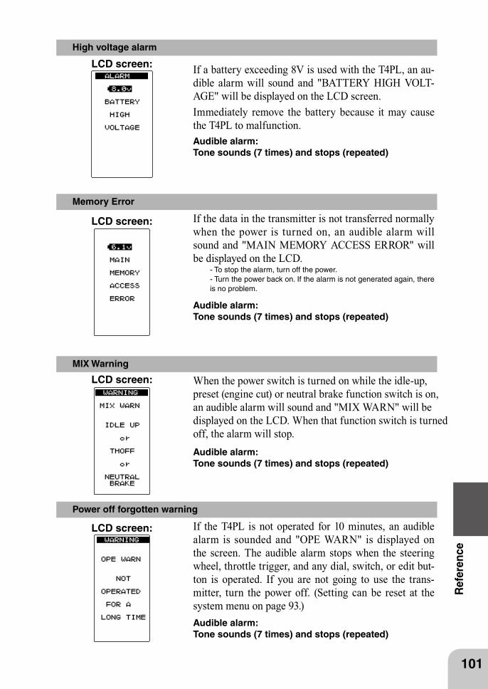
101
Ref
eren
ce
Power off forgotten warning
If the T4PL is not operated for 10 minutes, an audible alarm is sounded and "OPE WARN" is displayed on the screen. The audible alarm stops when the steering wheel, throttle trigger, and any dial, switch, or edit but-ton is operated. If you are not going to use the trans-mitter, turn the power off. (Setting can be reset at the system menu on page 93.)Audible alarm: Tone sounds (7 times) and stops (repeated)
LCD screen:
MIX Warning
When the power switch is turned on while the idle-up, preset (engine cut) or neutral brake function switch is on, an audible alarm will sound and "MIX WARN" will be displayed on the LCD. When that function switch is turned off, the alarm will stop.
LCD screen:
Audible alarm: Tone sounds (7 times) and stops (repeated)
High voltage alarm
If a battery exceeding 8V is used with the T4PL, an au-dible alarm will sound and "BATTERY HIGH VOLT-AGE" will be displayed on the LCD screen.Immediately remove the battery because it may cause the T4PL to malfunction.
LCD screen:
Audible alarm: Tone sounds (7 times) and stops (repeated)
Memory Error
If the data in the transmitter is not transferred normally when the power is turned on, an audible alarm will sound and "MAIN MEMORY ACCESS ERROR" will be displayed on the LCD.
- To stop the alarm, turn off the power. - Turn the power back on. If the alarm is not generated again, there is no problem.
LCD screen:
Audible alarm: Tone sounds (7 times) and stops (repeated)
Optional Parts
102
Reference
The following parts are available as 4PL options. Purchase them to match your applica-tion. For other optional parts, refer to our catalog.
Transmitter BatteryWhen purchasing a transmitter battery use the following:
Part nameHT5F1700B (6V/1700mAh) Ni-MH battery FT2F2100B (6.4V/2100mAh) Li-Fe battery Please do not use the transmitter batteries HT5F1700B and FT2F2100B as the receiver's battery.Since the transmitter's battery has an overload protection circuit, the output power will be shut down when the high current load is applied. This may result in runaway or fatal crash.
When requesting repairBefore requesting repair, read this instruction again and recheck your system. Should the problems continue, request as follows.
(Information needed for repair)
Describe the problem in as much detail as possible and send the letter along with the system in question.- Symptom (Including the conditions and when the problem occurred)- R/C System (Send transmitter, receiver and servos)- Model (Type of model, brand name and model number or kit name)- Detailed packing list (Make a list of all items sent in for repair)- Your name, address and telephone number.
(Warranty)
Read the Warranty card.- When requesting warranty service, send the card or some type of dated proof pur-chase.
103
Ref
eren
ce
FEDERAL COMMUNICATIONS COMMISSION INTERFERENCE STATEMENT (for U.S.A.)
This equipment has been tested and found to comply with the limits for a Class B digital device, pursuant to Part 15 of the FCC Rules. These limits are designed to provide rea-sonable protection against harmful interference in a residential installation.This equipment generates, uses and can radiate radio frequency energy and, if not in-stalled and used in accordance with the instructions, may cause harmful interference to radio communications. However, there is no guarantee that interference will not occur in a particular installation. If this equipment does cause harmful interference to radio or television reception, which can be determined by turning the equipment off and on, the user is encouraged to try to correct the interference by one or more of the following measures:--Reorient or relocate the receiving antenna.--Increase the separation between the equipment and receiver.--Connect the equipment into an outlet on a circuit different from that to which the re-ceiver is connected.--Consult the dealer or an experienced radio/TV technician for help.
CAUTION:To assure continued FCC compliance:Any changes or modifications not expressly approved by the grantee of this device could void the user’s authority to operate the equipment.
Exposure to Radio Frequency RadiationTo comply with FCC RF exposure compliance requirements, a separation distance of at least 20 cm must be maintained between the antenna of this device and all persons. This device must not be located or operating in conjunction with any other antenna or trans-mitter.

©Copyright 2010. No part of this manual may be reproduced in any form without prior permission. The contents of this manual are subject to change without prior notice. While this manual has been carefully written, there may be inadvertent errors or omissions. Please contact our service center if you feel that any corrections or clarifications should be made.
FUTABA CORPORATION Phone: +81 475 32 6982, Facsimile: +81 475 32 69831080 Yabutsuka, Chosei-mura, Chosei-gun, Chiba 299-4395, Japan
1M23N24105 ©FUTABA CORPORATION 2010, 12 (3)

R Digital Proportional
1M23N24105
R/C SystemR
INSTRUCTION MANUAL