Embed Size (px)
Citation preview
•
W I S C O N SI N
•
FU
SIO
N•
TECHNOLOGY• INS
TIT
UT
E
FUSION TECHNOLOGY INSTITUTE
UNIVERSITY OF WISCONSIN
MADISON WISCONSIN
A Lunar Volatiles Miner
Matthew E. Gajda
May 2006
UWFDM-1304
M.S. thesis.
A Lunar Volatiles Miner
Matthew E. Gajda
Fusion Technology InstituteUniversity of Wisconsin1500 Engineering Drive
Madison, WI 53706
http://fti.neep.wisc.edu
May 2006
UWFDM-1304
M.S. thesis.
1
A LUNAR VOLATILES MINER
by
Matthew E. Gajda
A thesis submitted in partial fulfillment of
The requirements for the degree of
Master of Science
In
Engineering Mechanics
At the
UNIVERSITY OF WISCONSIN � MADISON
2006

2

3
APPROVED TITLE Associate Dean for Research Grainger Professor of Nuclear Engineering Director, Fusion Technology Institute DATE

4
i
Abstract Mining the moon for lunar volatiles is a very complex task, which in turn requires a complex machine to effectively and efficiently extract the volatiles. In the early 1990�s a miner, deemed the Mark II, was designed to excavate, beneficiate, and heat the lunar regolith to extract solar wind volatiles: H2, 4He, 3He, CO2, CO, CH4, N2, H2O. The miner described in this thesis, the Mark III, is an improvement over the past design. Much more detail has been put into the design of each individual component, with complex calculations being used to calculate the mass and power of all the separate parts. Along with cataloging the masses, an optimization was also done on the volatile storage system, which allowed for further reduction in mass of the Mark III. Through all of the design changes made, it was possible to get the mass of the Mark III to less than 10 tonnes, nearly half that of the 18 tonne Mark II. This mass includes just the lunar miner, the support equipment and facilities, although outlined in this thesis, are a separate issue. The Mark III is also half as large as the Mark II, measuring 13.5 x 5.4 x 4.9 meters, without of the solar collector and radio frequency rectenna. The major downside of the new design is that it requires 350 kW to power all of the components, much higher than the 200 kW for the Mark II. This is due to the keeping the volatile loss below 10%, which was previously not thought to be an issue. The mass and size of the Mark III make it possible for the miner to be launched to the moon with a single large rocket or several smaller rockets, assuming that further developments are made in rockets over the next two decades. These improvements were done while retaining all of the capabilities of the Mark II, which entails extracting enough volatiles to support up to 47 lunar inhabitants.
ii
Acknowledgements I would like to thank my thesis advisor, Professor Gerald L. Kulcinski, for giving me the opportunity and support to complete this design. I would also like to thank John F. Santarius, Gregory I. Sviatoslavsky, and Igor N. Sviatoslavsky for their time and insights into my project. Together, these four people ensured that I consider all of the possible aspects of my design, along with enabling me to better explain some of the more complex design components, giving me greater confidence in my design. I also want to thank Harrison H. Schmitt for his input on the properties of lunar regolith and Ron Ross for his insight on compressors in space. I appreciate the help from Joan Welc-LePain on various administrative tasks, along with her ability to keep the office lively. I also appreciate the help from Dennis Bruggink with various technical issues and Pat Arnold with making sure that all of the graduation processes went smoothly. I want to acknowledge the Walter E. Kistler Foundation for partial financial support and the Gerald A. Soffen Memorial Fund for providing me with funds to attend a conference to present my research. Lastly, I want to thank my parents for their moral and financial support, not only in graduate school, but throughout my college career. Without having their love and affection behind me, my tasks would have been infinitely more difficult.
iii
Table of Contents Abstract ...................................................................................................................................... i Acknowledgements.................................................................................................................... ii Table of Contents ..................................................................................................................... iii Table of Figures...................................................................................................................... vii Table of Tables......................................................................................................................... ix Chapter 1 Introduction..................................................................................................... 1
1.1 Introduction............................................................................................................... 1 1.2 Importance of Volatiles............................................................................................. 2 1.3 References................................................................................................................. 4
Chapter 2 Background ..................................................................................................... 5 2.1 Mark II Design.......................................................................................................... 5
2.1.1 Mass and Power ................................................................................................ 8 2.2 References................................................................................................................. 8
Chapter 3 Design Parameters and Assumptions.......................................................... 10 3.1 Mark III Design....................................................................................................... 10 3.2 Capabilities ............................................................................................................. 10 3.3 Mass and Size Limitations ...................................................................................... 10 3.4 Gas Loss.................................................................................................................. 11 3.5 Tipping.................................................................................................................... 11 3.6 Lunar Environment ................................................................................................. 11 3.7 Technologies ........................................................................................................... 11 3.8 Assumptions............................................................................................................ 12
3.8.1 Regolith Properties.......................................................................................... 12 3.8.2 Calculations..................................................................................................... 12 3.8.3 Mining Operations .......................................................................................... 13
3.9 References............................................................................................................... 13 Chapter 4 Design Overview............................................................................................ 15
4.1 Pictures of Mark III................................................................................................. 15 4.2 Design Overview .................................................................................................... 17 4.3 Major Design Changes from Mark II...................................................................... 24
4.3.1 Placement of Sieves ........................................................................................ 24 4.3.2 Electrostatic Separator .................................................................................... 24 4.3.3 Fluidized Chamber Working Fluid ................................................................. 24 4.3.4 Hydrogen Separation ...................................................................................... 25 4.3.5 Locomotion ..................................................................................................... 25 4.3.6 Bucket Wheel Excavator................................................................................. 25 4.3.7 Electric Power Source..................................................................................... 25
4.4 References............................................................................................................... 25 Chapter 5 Mark III Components................................................................................... 26
5.1 Bucket Wheel.......................................................................................................... 26 5.1.1 Digging Process .............................................................................................. 26 5.1.2 Challenges - Rocks ......................................................................................... 26 5.1.3 Bucket Wheel Components............................................................................. 27
iv
5.1.4 Bucket Wheel Masses ..................................................................................... 31 5.1.5 Calculations..................................................................................................... 31
5.2 Belt Conveyors........................................................................................................ 35 5.2.1 Calculations..................................................................................................... 35 5.2.2 Mass and Power .............................................................................................. 37
5.3 Slide ........................................................................................................................ 38 5.4 Screw Conveyors .................................................................................................... 38
5.4.1 Vacuum Seal ................................................................................................... 39 5.4.2 Volatile Loss ................................................................................................... 39
5.5 Sieves ...................................................................................................................... 40 5.6 Fluidized Chamber.................................................................................................. 40 5.7 Heater...................................................................................................................... 43 5.8 Electrostatic Separation .......................................................................................... 44 5.9 Volatile Storage System.......................................................................................... 45
5.9.1 Compressors.................................................................................................... 45 5.9.2 Intercoolers ..................................................................................................... 46 5.9.3 Gas Storage Tanks .......................................................................................... 47 5.9.4 Results............................................................................................................. 47
5.10 Ejection Mechanism................................................................................................ 49 5.11 Fuel Cells ................................................................................................................ 50 5.12 Solar Collector ........................................................................................................ 51 5.13 RF Rectenna............................................................................................................ 53
5.13.1 Efficiencies ..................................................................................................... 53 5.13.2 Heating............................................................................................................ 54 5.13.3 Rayleigh Distance ........................................................................................... 54 5.13.4 Mass ................................................................................................................ 55
5.14 Locomotion ............................................................................................................. 55 5.14.1 Tracks.............................................................................................................. 55 5.14.2 Motors ............................................................................................................. 56
5.15 Chassis .................................................................................................................... 57 5.16 Enclosure................................................................................................................. 57 5.17 References............................................................................................................... 57
Chapter 6 Support Equipment ...................................................................................... 60 6.1 Large Stationary Dish ............................................................................................. 60 6.2 RF Antenna ............................................................................................................. 60 6.3 Photovoltaic Cell Array .......................................................................................... 61 6.4 Tanker Truck........................................................................................................... 61 6.5 Cryogenic Separation and Storage Facility............................................................. 61 6.6 Maintenance Facility and Vehicle .......................................................................... 62 6.7 References............................................................................................................... 62
Chapter 7 Results ............................................................................................................ 64 7.1 Tipping.................................................................................................................... 64 7.2 Volatile Loss ........................................................................................................... 64 7.3 Mass ........................................................................................................................ 64
7.3.1 Material Usage ................................................................................................ 65
v
7.3.2 Titanium.......................................................................................................... 66 7.3.3 Steel................................................................................................................. 66 7.3.4 Stainless Steel ................................................................................................. 67
7.4 Power ...................................................................................................................... 67 7.5 Comparison with Mark II........................................................................................ 68 7.6 References............................................................................................................... 70
Chapter 8 Mining Issues................................................................................................. 71 8.1 Gas Extraction......................................................................................................... 71 8.2 Mass Flow Rates ..................................................................................................... 71 8.3 Dust ......................................................................................................................... 71 8.4 Material Embrittlement........................................................................................... 72 8.5 Material Erosion...................................................................................................... 72 8.6 References............................................................................................................... 72
Chapter 9 Recommended Future Work ....................................................................... 73 9.1 Safety Factor ........................................................................................................... 73 9.2 Continuous Mining ................................................................................................. 73 9.3 Power Sources......................................................................................................... 73
9.3.1 Nuclear............................................................................................................ 73 9.3.2 Thermophotovoltaics ...................................................................................... 73 9.3.3 Power Cord ..................................................................................................... 74
9.4 Design Changes ...................................................................................................... 74 9.4.1 Bucket Wheel Excavator................................................................................. 74 9.4.2 Power .............................................................................................................. 74 9.4.3 Regolith Heating ............................................................................................. 75 9.4.4 Vacuum Seal ................................................................................................... 75 9.4.5 Optics .............................................................................................................. 75
9.5 Agitation ................................................................................................................. 76 9.6 Properties of the Regolith ....................................................................................... 76 9.7 Dust ......................................................................................................................... 76 9.8 Spiral Mining .......................................................................................................... 77 9.9 Extracting Metallics ................................................................................................ 77 9.10 References............................................................................................................... 77
Chapter 10 Conclusion ..................................................................................................... 79 Appendix A Mineable Area ........................................................................................... 80
A.1 Mineable Area......................................................................................................... 80 A.2 References............................................................................................................... 82
Appendix B Material Properties................................................................................... 83 B.1 Ti-6Al-4V ............................................................................................................... 83 B.2 Ti-6Al-2Sn-2Zr-2Mo-2Cr-0.25Si ........................................................................... 84 B.3 Ti-6Al-6V-2Sn........................................................................................................ 85 B.4 D-6a Steel................................................................................................................ 86 B.5 6150 Steel................................................................................................................ 87 B.6 316 Stainless Steel .................................................................................................. 88 B.7 21Cr-6Ni-9Mn Stainless Steel ................................................................................ 90 B.8 Carbon-Carbon Composite ..................................................................................... 91
vi
B.9 Aluminized Mylar................................................................................................... 92 B.10 Molybdenum Alloy................................................................................................. 93 B.11 Al2O3 ....................................................................................................................... 94 B.12 References............................................................................................................... 95
vii
Table of Figures Figure 1-1. Conceptual model of the Mark III miner without the enclosure........................... 1 Figure 2-1. Conceptual drawing of the Mark I ........................................................................ 5 Figure 2-2. Conceptual drawing of the Mark II....................................................................... 5 Figure 2-3. Side view of heater in Mark II6 ............................................................................. 7 Figure 4-1. Side View of the Mark III, with human .............................................................. 15 Figure 4-2. Side isometric view of the solar collector with radio frequency rectenna .......... 15 Figure 4-3. Rear isometric view of the Mark III.................................................................... 16 Figure 4-4. Side isometric view of the Mark III, with human ............................................... 17 Figure 4-5. Bottom isometric view of the Mark III ............................................................... 17 Figure 4-6. Processing schematic for the regolith and evolved gasses.................................. 19 Figure 4-7. Process of concentrating and redirecting the sunlight into the miner heater (not to
scale) ............................................................................................................................... 20 Figure 4-8. Enlarged side view of the solar collector on the miner for the sunlight
concentrating process (not to scale)................................................................................ 20 Figure 4-9. Side view of the optics for solar collector and stationary collector dishes ......... 21 Figure 4-10. Regolith schematic indicating different mass flow rates and particle sizes...... 23 Figure 5-1. Picture of bucket wheel with hole in thin circular ring for regolith to exit buckets
......................................................................................................................................... 28 Figure 5-2. Bucket wheel frame, boom, and buckets ............................................................ 29 Figure 5-3. Bucket wheel support and swivel attachment to the BW frame and chassis ...... 30 Figure 5-4. Detailed view of the bucket wheel support and swivel....................................... 30 Figure 5-5. ANSYS® results for BW frame........................................................................... 34 Figure 5-6. Enlarged view of stress concentration on BW frame.......................................... 35 Figure 5-7. Cross-sectional area of the regolith on the conveyor belt ................................... 36 Figure 5-8. Schematic of the Mark III labeling all of the conveyors..................................... 38 Figure 5-9. Graph of percentage of gas lost vs. the internal pressure in the miner with 50%
void fraction .................................................................................................................... 40 Figure 5-10. Diagram of the regolith and gas flow inside of the fluidized chamber ............. 41 Figure 5-11. Gas release pattern for Apollo 11 soil 10086,16. Heating rate 4ûC/min14. ...... 44 Figure 5-12. Schematic showing the flow of the volatiles through the compressors and
intercoolers...................................................................................................................... 49 Figure 5-14. Schematic of excavating and ejecting regolith (not to scale)............................ 50 Figure 5-15. Transmission efficiency vs. the unitless parameter Tau, interpolated from data27
......................................................................................................................................... 54 Figure 5-16. MATTRACKS® wheel replacing tracks31 ........................................................ 55 Figure 5-17. Mark III miner with enclosure, shown in white................................................ 57 Figure 6-1. Radiator area needed to cryogenically separate the given volatiles during one
lunar night ....................................................................................................................... 62 Figure 7-1. Chart of masses for each component group of the Mark III ............................... 65 Figure 7-2. Material breakdown of the Mark III mass........................................................... 65 Figure 7-3. Mass breakdown of the different types of titanium used .................................... 66 Figure 7-4. Mass breakdown of the different types of steel used .......................................... 67 Figure 7-5. Mass breakdown, by mass, of the different types of stainless steel used............ 67
viii
Figure 7-6. Chart of power usage for the Mark III ................................................................ 68 Figure 10-1. Mineable area with 12 meter and larger diameter craters with 400 meter squares
(left) and 300 meter squares with extensions (right)1 ..................................................... 81 Figure 10-2. Mineable area with 24 meter and larger diameter craters with 400 meter squares
(left) and 300 meter squares with extensions (right)1 ..................................................... 82
ix
Table of Tables Table 1-1. Amount of volatiles extracted per year by the Mark III1........................................ 2 Table 1-2. Amount of volatiles required for inhabitants on the moon and the number of
inhabitants supported by the Mark III3 ............................................................................. 2 Table 2-1. Mark II Parameters ................................................................................................. 6 Table 2-2. Power required for the Mark II5 ............................................................................. 8 Table 4-1. Table of mass flow rates and particle sizes for Figure 4-9................................... 24 Table 5-1. Component masses for the BWE.......................................................................... 31 Table 5-2. Mass and power requirements for all of the belt conveyors................................. 37

x
This page left intentionally blank

xi
1
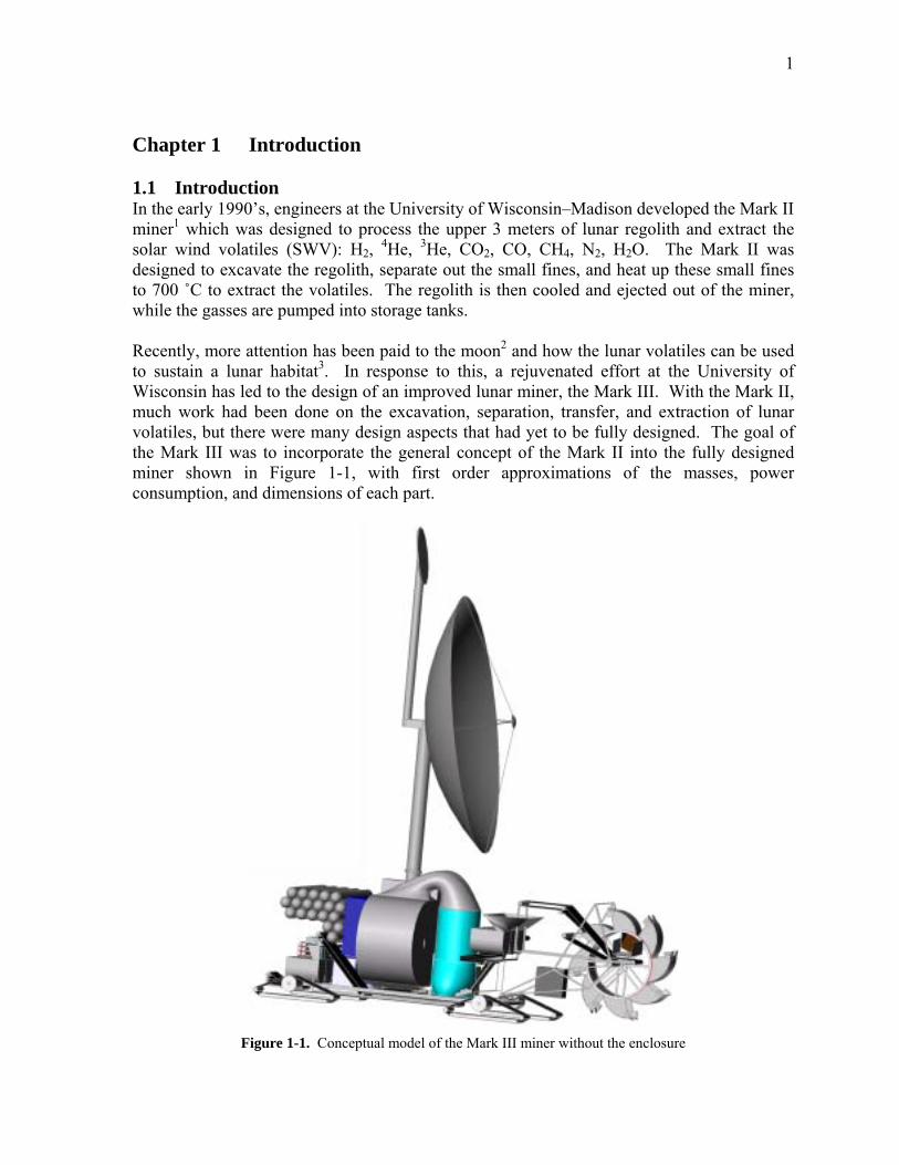
Chapter 1 Introduction 1.1 Introduction In the early 1990�s, engineers at the University of Wisconsin�Madison developed the Mark II miner1 which was designed to process the upper 3 meters of lunar regolith and extract the solar wind volatiles (SWV): H2, 4He, 3He, CO2, CO, CH4, N2, H2O. The Mark II was designed to excavate the regolith, separate out the small fines, and heat up these small fines to 700 ûC to extract the volatiles. The regolith is then cooled and ejected out of the miner, while the gasses are pumped into storage tanks. Recently, more attention has been paid to the moon2 and how the lunar volatiles can be used to sustain a lunar habitat3. In response to this, a rejuvenated effort at the University of Wisconsin has led to the design of an improved lunar miner, the Mark III. With the Mark II, much work had been done on the excavation, separation, transfer, and extraction of lunar volatiles, but there were many design aspects that had yet to be fully designed. The goal of the Mark III was to incorporate the general concept of the Mark II into the fully designed miner shown in Figure 1-1, with first order approximations of the masses, power consumption, and dimensions of each part.
Figure 1-1. Conceptual model of the Mark III miner without the enclosure
2
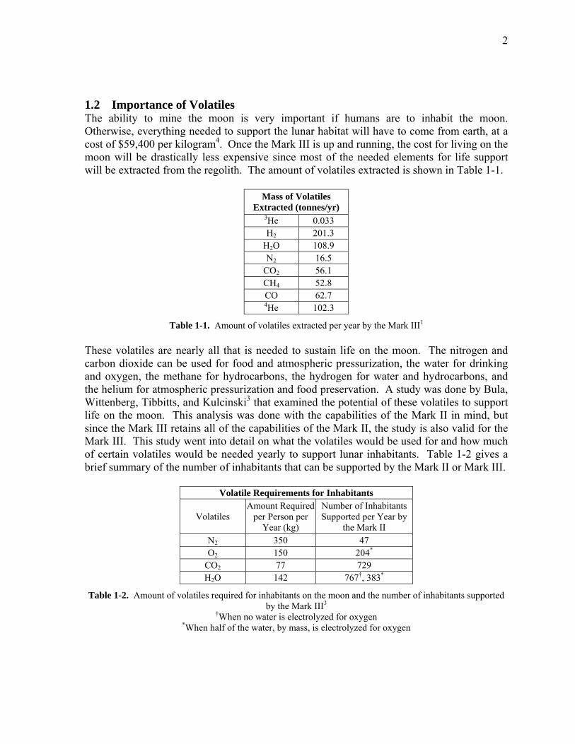
1.2 Importance of Volatiles The ability to mine the moon is very important if humans are to inhabit the moon. Otherwise, everything needed to support the lunar habitat will have to come from earth, at a cost of $59,400 per kilogram4. Once the Mark III is up and running, the cost for living on the moon will be drastically less expensive since most of the needed elements for life support will be extracted from the regolith. The amount of volatiles extracted is shown in Table 1-1.
Mass of Volatiles Extracted (tonnes/yr)
3He 0.033 H2 201.3
H2O 108.9 N2 16.5
CO2 56.1 CH4 52.8 CO 62.7 4He 102.3
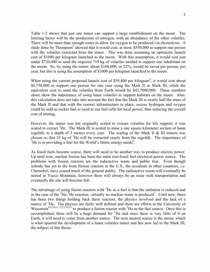
Table 1-1. Amount of volatiles extracted per year by the Mark III1 These volatiles are nearly all that is needed to sustain life on the moon. The nitrogen and carbon dioxide can be used for food and atmospheric pressurization, the water for drinking and oxygen, the methane for hydrocarbons, the hydrogen for water and hydrocarbons, and the helium for atmospheric pressurization and food preservation. A study was done by Bula, Wittenberg, Tibbitts, and Kulcinski3 that examined the potential of these volatiles to support life on the moon. This analysis was done with the capabilities of the Mark II in mind, but since the Mark III retains all of the capabilities of the Mark II, the study is also valid for the Mark III. This study went into detail on what the volatiles would be used for and how much of certain volatiles would be needed yearly to support lunar inhabitants. Table 1-2 gives a brief summary of the number of inhabitants that can be supported by the Mark II or Mark III.
Volatile Requirements for Inhabitants
Volatiles Amount Required
per Person per Year (kg)
Number of Inhabitants Supported per Year by
the Mark II N2 350 47 O2
150 204*
CO2 77 729 H2O 142 767�, 383*
Table 1-2. Amount of volatiles required for inhabitants on the moon and the number of inhabitants supported by the Mark III3
�When no water is electrolyzed for oxygen
*When half of the water, by mass, is electrolyzed for oxygen
3
Table 1-2 shows that just one miner can support a large establishment on the moon. The limiting factor will be the production of nitrogen, with an abundance of the other volatiles. There will be more than enough water to allow for oxygen to be produced via electrolysis. A study done by Thompson5 showed that it would cost, at most, $550,000 to support one person with the volatiles extracted from the miner. This was done assuming an optimistic launch cost of $1000 per kilogram launched to the moon. With this assumption, it would cost just under $720,000 to send the required 719 kg of volatiles needed to support one inhabitant on the moon. So, by using the miner, about $160,000, or 22%, would be saved per person, per year, but this is using the assumption of $1000 per kilogram launched to the moon. When using the current proposed launch cost of $59,400 per kilogram4, it would cost about $6,750,000 to support one person for one year using the Mark II or Mark III, while the equivalent cost to send the volatiles from Earth would be $42,7000,000. These numbers alone show the importance of using lunar volatiles to support habitats on the moon. Also, this calculation does not take into account the fact that the Mark III is nearly half the mass of the Mark II and that with the correct infrastructure in place, excess hydrogen and oxygen could be sold as rocket fuel or used to run fuel cells for local power, thus reducing the overall cost of mining. However, the miner was not originally scaled to extract volatiles for life support, it was scaled to extract 3He. The Mark III is scaled to mine a one square kilometer section of lunar regolith, to a depth of 3 meters every year. The scaling of the Mark II & III miners was chosen so that 33 kg of 3He will be extracted yearly from the regolith. The importance of 3He is in providing a fuel for the World�s future energy needs6. As fossil fuels become scarce, there will need to be another way to produce electric power. Up until now, nuclear fission has been the main non-fossil fuel electrical power source. The problems with fission reactors are the radioactive waste and public fear. Even though nobody has yet to die from fission reactors in the U.S., the accidents in other countries, i.e. Chernobyl, have scared much of the general public. The radioactive waste will eventually be stored in Yucca Mountain, however there will always be an issue with transportation and eventually the site will become full. The advantage of using fusion reactors with 3He as a fuel is that the radiation is reduced and in the case of the 3He-3He reaction, virtually no nuclear waste is produced7. Until now, there has been two things holding back these reactors, the physics involved and the lack of a source of 3He. The physics are fairly well defined and there are efforts at the University of Wisconsin8,9,10,11,1213,14,15 to produce a fusion reactor with 3He as the fuel source. Once this is accomplished, there will be a huge demand for 3He and since there is very little of it on Earth, it will need to come from another source. The next nearest source is the moon, which is what spurred the development of a lunar volatiles miner and has now led to the Mark III, the subject of this thesis.
4
1.3 References [1] Sviatoslavsky, I. N. (1993, July). Coaxing He3 from Lunar Regolith; Processes and
Challenges. Proceedings of the Second Wisconsin Symposium on Helium-3 and Fusion Power, Madison, WI
[2] Bush, President G. W. (2004, January 14). President Bush Announces New Vision for Space Exploration Plan. [Television Broadcast]. Washington D.C.
[3] Bula, R. J., Wittenberg, L. J., Tibbitts, T. W., Kulcinski, G. L. (1998 April). Potential of Derived Volatiles for Life Support. Proceedings of the Second Lunar Base Conference, Houston , TX
[4] Schmitt, H. H. (2006). Return to the Moon. New York: Copernicus Books [5] Thompson, Howard E. (1993 July). Cost of 3He from the Moon. Proceedings of the
Second Wisconsin Symposium on Helium-3 and Fusion Power, Madison, WI [6] Kulcinski, G. L. (1993 April). Helium-3 Fusion Reactors – A clean and Safe Source
of Energy in the 21st Century. Proceedings of the 9th National Space Symposium, Colorado Springs, CO
[7] Kulcinski, G. L. and Schmitt, H. H. (2000 July). Nuclear Power Without Radioactive Waste – The Promise of Lunar Helium-3. Proceedings of the Second Annual Lunar Development Conference, �Return to the Moon II,� Las Vegas, NV
[8] Kulcinski, G. L., Emmert, G. A., Blanchard, J. P., El-Guebaly, L. A., Khater, H. T., Maynard, C.W., et al. (1990 October). Apollo-L3, An Advanced Fuel Fusion Power Reactor Utilizing Direct and Thermal Energy Conversion. Proceedings of the 9th Topical Meeting on the Technology of Fusion Energy, Oak Brook, IL
[9] Bespoludennov, S. G., Khripunov, V. I., Pistunovich, V. I., Emmert, G. A., Santarius, J. F., Kulcinski, G. L. (1993). D-3He Tokamak Reactor. Proceedings of the 14th IAEA Conference, Vienna, Austria
[10] Kulcinski, G. L., Blanchard, J. P., Emmert, G. A., El-Guebaly, L. A., Khater, H. Y., Maynard, C. W., et al (1992). Safety and Environmental Characteristics of Recent D-3He and DT Tokamak Power Reactors. Fusion Technology 21, 1779
[11] Bathke, C. G., Werley, K. A., Miller, R. L., Krakowski, R. A., Santarius, J. F. (1992). The ARIES-III D-3He Tokamak Reactor: Design-Point Determination and Parametric Studies. Proceedings of the 14th IEEE Symposium on Fusion Engineering, New York, NY
[12] Najmabadi, F., Conn, R. W., et al. (1992). The ARIES-III D-3He Tokamak-Reactor Study. Proceedings of the 14th IEEE Symposium on Fusion Engineering, New York, NY
[13] Santarius, J. F., Kulcinski, G. L., El-Guebaly, L. A., Khater, H. Y. (1998). Could Advanced Fusion Fuels Be Used with Today's Technology?. Journal of Fusion Energy 17, 33
[14] Kernbichler, W., Heindler, M., Momota, H., Tomita, Y., Ishida, A., Ohi, S., et al. (1991). D-3He in Field Reversed Configurations—Ruby: an International Reactor Study. Proceedings of the 14th IAEA Conference, Vienna, Austria
[15] Post, R. F. and Santarius, J. F. (1992). Open Confinement Systems and the D-3He Reaction. Fusion Technology, 22, 13
5
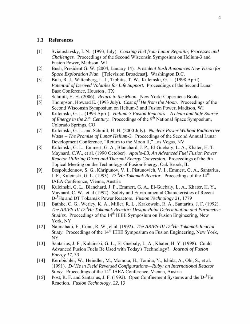
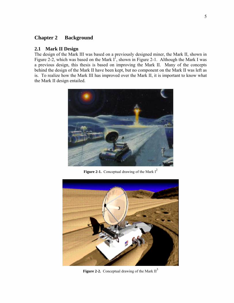
Chapter 2 Background 2.1 Mark II Design The design of the Mark III was based on a previously designed miner, the Mark II, shown in Figure 2-2, which was based on the Mark I1, shown in Figure 2-1. Although the Mark I was a previous design, this thesis is based on improving the Mark II. Many of the concepts behind the design of the Mark II have been kept, but no component on the Mark II was left as is. To realize how the Mark III has improved over the Mark II, it is important to know what the Mark II design entailed.
Figure 2-1. Conceptual drawing of the Mark I2
Figure 2-2. Conceptual drawing of the Mark II3
6
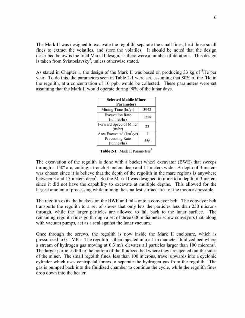
The Mark II was designed to excavate the regolith, separate the small fines, heat those small fines to extract the volatiles, and store the volatiles. It should be noted that the design described below is the final Mark II design, as there were a number of iterations. This design is taken from Sviatoslavsky3, unless otherwise stated. As stated in Chapter 1, the design of the Mark II was based on producing 33 kg of 3He per year. To do this, the parameters seen in Table 2-1 were set, assuming that 80% of the 3He in the regolith, at a concentration of 10 ppb, would be collected. These parameters were set assuming that the Mark II would operate during 90% of the lunar days.
Selected Mobile Miner Parameters
Mining Time (hr/yr) 3942 Excavation Rate
(tonnes/hr) 1258
Forward Speed of Miner (m/hr) 23
Area Excavated (km2/yr) 1 Processing Rate
(tonnes/hr) 556
Table 2-1. Mark II Parameters4 The excavation of the regolith is done with a bucket wheel excavator (BWE) that sweeps through a 150º arc, cutting a trench 3 meters deep and 11 meters wide. A depth of 3 meters was chosen since it is believe that the depth of the regolith in the mare regions is anywhere between 3 and 15 meters deep5. So the Mark II was designed to mine to a depth of 3 meters since it did not have the capability to excavate at multiple depths. This allowed for the largest amount of processing while mining the smallest surface area of the moon as possible. The regolith exits the buckets on the BWE and falls onto a conveyor belt. The conveyor belt transports the regolith to a set of sieves that only lets the particles less than 250 microns through, while the larger particles are allowed to fall back to the lunar surface. The remaining regolith fines go through a set of three 0.8 m diameter screw conveyors that, along with vacuum pumps, act as a seal against the lunar vacuum. Once through the screws, the regolith is now inside the Mark II enclosure, which is pressurized to 0.1 MPa. The regolith is then injected into a 1 m diameter fluidized bed where a stream of hydrogen gas moving at 0.3 m/s elevates all particles larger than 100 microns6. The larger particles fall to the bottom of the fluidized bed where they are ejected out the sides of the miner. The small regolith fines, less than 100 microns, travel upwards into a cyclonic cylinder which uses centripetal forces to separate the hydrogen gas from the regolith. The gas is pumped back into the fluidized chamber to continue the cycle, while the regolith fines drop down into the heater.
7
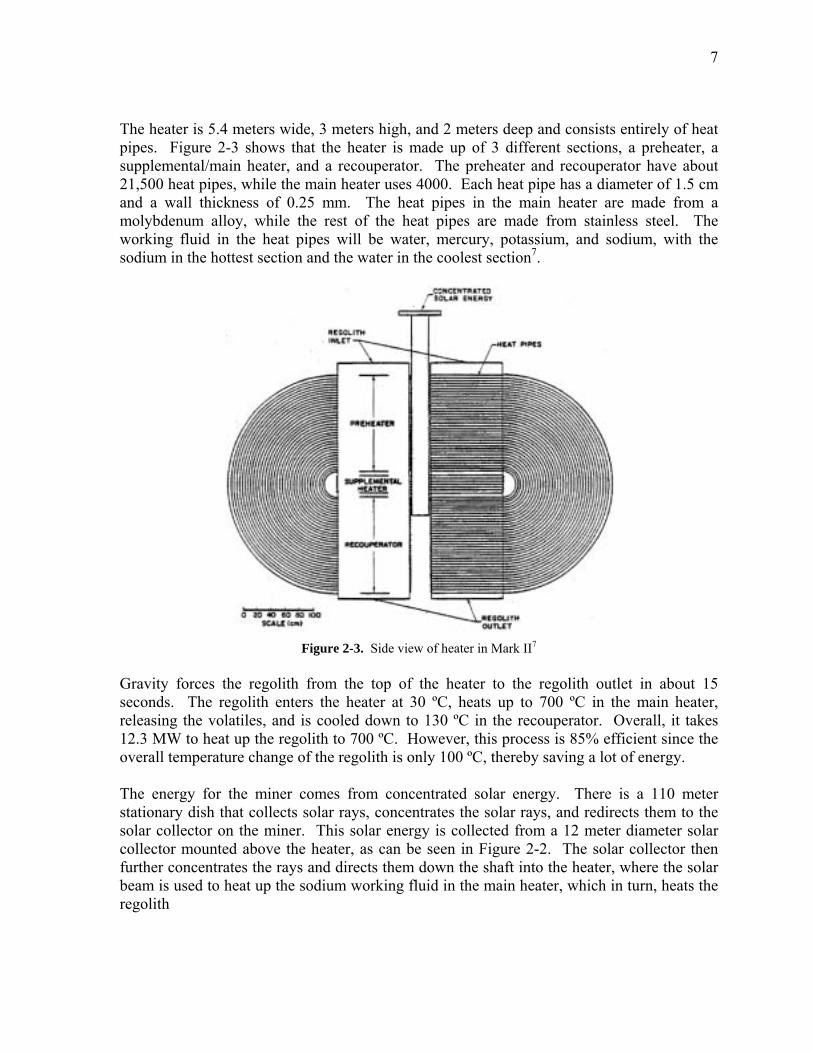
The heater is 5.4 meters wide, 3 meters high, and 2 meters deep and consists entirely of heat pipes. Figure 2-3 shows that the heater is made up of 3 different sections, a preheater, a supplemental/main heater, and a recouperator. The preheater and recouperator have about 21,500 heat pipes, while the main heater uses 4000. Each heat pipe has a diameter of 1.5 cm and a wall thickness of 0.25 mm. The heat pipes in the main heater are made from a molybdenum alloy, while the rest of the heat pipes are made from stainless steel. The working fluid in the heat pipes will be water, mercury, potassium, and sodium, with the sodium in the hottest section and the water in the coolest section7.
Figure 2-3. Side view of heater in Mark II7
Gravity forces the regolith from the top of the heater to the regolith outlet in about 15 seconds. The regolith enters the heater at 30 ºC, heats up to 700 ºC in the main heater, releasing the volatiles, and is cooled down to 130 ºC in the recouperator. Overall, it takes 12.3 MW to heat up the regolith to 700 ºC. However, this process is 85% efficient since the overall temperature change of the regolith is only 100 ºC, thereby saving a lot of energy. The energy for the miner comes from concentrated solar energy. There is a 110 meter stationary dish that collects solar rays, concentrates the solar rays, and redirects them to the solar collector on the miner. This solar energy is collected from a 12 meter diameter solar collector mounted above the heater, as can be seen in Figure 2-2. The solar collector then further concentrates the rays and directs them down the shaft into the heater, where the solar beam is used to heat up the sodium working fluid in the main heater, which in turn, heats the regolith
8
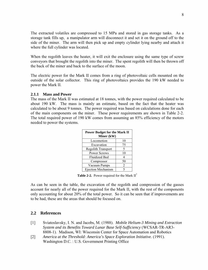
The extracted volatiles are compressed to 15 MPa and stored in gas storage tanks. As a storage tank fills up, a manipulator arm will disconnect it and set it on the ground off to the side of the miner. The arm will then pick up and empty cylinder lying nearby and attach it where the full cylinder was located. When the regolith leaves the heater, it will exit the enclosure using the same type of screw conveyors that brought the regolith into the miner. The spent regolith will then be thrown off the back of the miner and back to the surface of the moon. The electric power for the Mark II comes from a ring of photovoltaic cells mounted on the outside of the solar collector. This ring of photovoltaics provides the 190 kW needed to power the Mark II. 2.1.1 Mass and Power The mass of the Mark II was estimated at 18 tonnes, with the power required calculated to be about 190 kW. The mass is mainly an estimate, based on the fact that the heater was calculated to be about 9 tonnes. The power required was based on calculations done for each of the main components on the miner. These power requirements are shown in Table 2-2. The total required power of 190 kW comes from assuming an 85% efficiency of the motors needed to power the systems.
Power Budget for the Mark II Miner (kW)
Locomotion 10 Excavation 75
Regolith Transport 5 Power Screws 10 Fluidized Bed 4 Compressor 50
Vacuum Pumps 2 Ejection Mechanism 5
Table 2-2. Power required for the Mark II7 As can be seen in the table, the excavation of the regolith and compression of the gasses account for nearly all of the power required for the Mark II, with the rest of the components only accounting for about 20% of the total power. So it can be seen that if improvements are to be had, these are the areas that should be focused on. 2.2 References [1] Sviatoslavsky, I. N. and Jacobs, M. (1988). Mobile Helium-3 Mining and Extraction
System and its Benefits Toward Lunar Base Self-Sufficiency (WCSAR-TR-AR3-8808-1). Madison, WI: Wisconsin Center for Space Automation and Robotics
[2] America at the Threshold: America’s Space Exploration Initiative. (1991). Washington D.C. : U.S. Government Printing Office
9
[3] Sviatoslavsky, I.N. (1993 February). The Challenge of Mining He-3 on the Lunar
Surface: How All the Parts Fit Together. Proceedings of Space 94, The 4th International Conference and Exposition of Engineering, Construction and Operations in Space, Albuquerque, NM
[4] Sviatoslavsky, I.N. and Jacobs, M. (1988). Mobile Helium-3 Mining and Extraction System and its Benefits Toward Lunar Base Self-Sufficiency (WCSAR-TR-AR3-8808-1). Madison, WI: Wisconsin Center for Space Automation and Robotics
[5] Heiken, Grant H., Vaniman, David T., French, Bevan M. (1991). Lunar Sourcebook, a user’s guide to the moon. Cambridge : Cambridge University
[6] Sviatoslavsky, Igor, N. (1992 January). Lunar He-3 Mining: Improvements on the Design of the UW Mark II Lunar Miner. Proceedings of Space 92, The 3rd International Conference and Exposition of Engineering, Construction and Operations in Space, Denver, CO
[7] Sviatoslavsky, I. N. (1993, July). Coaxing He3 from Lunar Regolith; Processes and Challenges. Proceedings of the Second Wisconsin Symposium on Helium-3 and Fusion Power, Madison, WI
10
Chapter 3 Design Parameters and Assumptions 3.1 Mark III Design The Mark III design, described in Chapters 4 and 5, only includes the design of the miner. All of the support systems and facilities needed to maintain the mining operations are not included in the mass and power requirements for the miner. There are some basic concepts for the support equipment, with some calculations done in Chapter 6. Other than that, all other efforts in this thesis were devoted to the design of the Mark III. Also, this thesis concentrates on the mechanical aspect of the design, with the electrical circuitry left to future designs. 3.2 Capabilities Solar energy will be used to heat the regolith and indirectly power the miner through the use of RF beaming, which limits mining operations to lunar days only, with any needed maintenance performed during the lunar night. This decision, along with the assumption that the miner will be operating during 90% of the lunar days, leads to about 4000 mining hours per year. These numbers lead to a required excavation rate of about 1300 tonnes of lunar regolith per hour to get 33 kg of 3He per year and yield 69 kg/hr of lunar volatiles. Table 1-1 shows the amount of volatiles extracted by the Mark III. Since the Mark III was designed to have the same capabilities as the Mark II, the requirements in Table 2-1 were also used to guide the design of the Mark III. 3.3 Mass and Size Limitations One goal of the Mark III was to have a miner that could be flown to the moon in one rocket. None of today�s rockets are designed with the intent of sending massive objects into lunar orbit, however, if we are to go back to the moon to set up a settlement, the rockets of the future will certainly have much greater capabilities. According to Boeing1, the Delta IV rocket will be capable of launching 9956 kg into a trans lunar orbit. Therefore, the mass of the miner was set to a limit of 10 tonnes, even though the mass of the payload that actually reaches the moon will be much less. But it is assumed that the launch capabilities will greatly increase before the moon becomes a permanent habitat for humans. The target of 10 tonnes led to a miner that can fit into a rocket with a payload diameter of 5.4 meters and a length of 13.5 meters. These dimensions do not include the solar collector or radio frequency (RF) receiving antenna, or rectenna, shown in Figure 1-1 as the two dishes above the main miner body. The solar collector and RF rectenna assembly will be collapsible, with the solar collector dish assembled from multiple curved pieces of aluminized mylar. This allows for the solar collector and RF rectenna assembly to fit into much smaller rockets and be sent separately to the moon. The maximum diameter of the Delta IV payload is 4.57 meters, so the Mark III will not fit, fully assembled, into this rocket. This is due to the massive heater, so either the heater will need to be shipped in a separate rocket, or the miner will need to be further disassembled to fit into the payload compartment of the Delta IV. However, another possibility is that the
11
miner will be flown to the moon in much smaller pieces, with multiple rockets, and assembled on-site. 3.4 Gas Loss To ensure that the miner remains efficient and does not adversely affect the lunar environment, gas loss must be kept at a minimum. To do this, it was determined that the calculable gas losses must remain under 10% of the overall extracted volatiles. The calculable losses are the losses at the regolith entrance and exit of the miner, although, as will be later shown, the main problem with gas losses occurs at the exit. There may be other areas of gas loss, but these will be very small when compared to the losses at the regolith exit. 3.5 Tipping Tipping is only a worry when the miner is not excavating since when in the mine, the miner will be on mainly level ground due to the level digging of the miner. At worst, the miner will be traveling down or up a slope of a few degrees, which will not be a problem at all. The only worry is when the miner is traversing from one mine to another or going to or leaving the main base. According to the Lunar Sourcebook2, the angle of repose of the regolith, the maximum angle of displaced regolith, is about 40º. In other words, the maximum angle of displaced regolith is 40º. However the Mark III will be able to stay away from these areas and stick to the flatter areas of the lunar surface. To be safe, the miner will be limited to slopes of 30º or less. This should provide enough flexibility to easily get to and from the mine. 3.6 Lunar Environment The Lunar Sourcebook2 speaks of a phenomenon that �may generate clouds of electrostatically-supported dust.� As the terminator, boundary between day and night, moves across the lunar surface, the fine regolith particles can become electrostatically charged and form a cloud of dust. This dust could cover the entire surface of the Mark III, including the optics, which would be detrimental to mining operations, since the Mark III relies on solar energy for mining operations. So the Mark III will leave the mine with enough time to get into maintenance facility before the terminator crosses its path. It will also stay in the maintenance facility until after the terminator crosses before heading back out to the mine. If something should keep the Mark III out while the terminator passes, it will be covered to protect the dust-sensitive optics. 3.7 Technologies 2017 is the year NASA believes it would be possible to get a pilot program to extract water/hydrogen from the regolith3, so many of the advanced technologies on this miner will be much further evolved in the 11 years until it is feasible to mine the moon. So some of the components used on the Mark III, i.e. RF beaming, fuel cells, and photovoltaics, are using technologies that are under development. However, these technologies should be fully developed by 2017.
12
3.8 Assumptions Many assumptions were made during the process of designing the Mark III. Some of these assumptions were done to simplify the process, others were needed to make up for a lack of information. However, all of the assumptions are based on factual data and were only used when absolutely required. 3.8.1 Regolith Properties The biggest unknown throughout this project has been the exact properties of the regolith. Without further studies and analysis these properties will remain a mystery. To complete the Mark III, some assumptions needed to be made regarding the regolith properties. One assumption is that the regolith density is 1800 kg/m3. The density of the regolith varies with depth and location on the lunar surface, so to be conservative, a higher than average density was chosen. Most measurements put the density between 1400 � 1700 kg/m3. However, the deepest of these measurements was 60 cm, and the Mark III will be digging down to 3 meters2, so a higher density is felt to be more realistic. The other major assumption was needed for the screw conveyor calculations. As expected, much of the calculations depends on the material being used, and more specifically the material class. So the regolith was assumed to have properties similar to dry clay or brick fines, or pre-mix dry concrete. These materials have similar densities, are quite abrasive, and consist mainly of small fines, all of which match the description of lunar regolith. 3.8.2 Calculations All the calculations done on the various miner components were at steady state operations. The calculations will vary dramatically from start up to steady state, however, the ramp-up time will be quite small when compared to the steady state operations. So this research concentrated on the steady state operations of the Mark III. For the compressor calculations, the gas was assumed to be ideal and undergoing an adiabatic, polytropic process, with the constant, n, equal to 1.35. This value of n was chosen since typical values tend to range from 1.3 and 1.4. Also, the heat transfer in the compressor was assumed to be negligible when compared to temperature change due to the compression. This is easy to see since the change in temperature due to the compression is quite large, between 100 and 400 ºC, while very little temperature change will be seen from the transfer of heat from the gas to the compressor. The heat transfer in the gas storage tanks is also assumed to be negligible. This is not much of an assumption since the tanks will quickly take on the temperature of the volatiles because the mass of the volatiles in the tanks far outweighs the mass of the tanks. These tanks will also be highly insulated, so any effects from the lunar environment will be minimal. Another assumption that was needed for the compressors and gas storage tanks is that the volatiles act as an ideal gas. This assumption is based on the fact that the most prevalent gas
13
is hydrogen, followed by helium. Both these gasses are ideal gasses and do not deviate much from the ideal gas laws even at high pressures, so this assumption is fairly realistic. Another heat transfer assumption is that there will be negligible heat transfer in the fluidized chamber between the volatiles and regolith. The volatiles will enter the fluidized chamber at around 130 ºC and the regolith will be around 30 ºC. So there will be some heat transfer between volatiles and regolith, which will heat up the fine regolith particles entering the heater. But because the specific heat of the volatiles is so low, this temperature change should be minimal. 3.8.3 Mining Operations The mining operations will always be within 10 km of the base camp. This limitation is set so that maintenance crews will be able to travel to and from the mine without endangering their safety. Even this distance is quite far since the farthest any of the Apollo rovers traveled was 20.1 kilometers4. So any new rover will need to be much more durable and capable of traveling for extended periods of time. This also means that the Mark III must be capable of traveling 10 km without the use of solar power. It is assumed that the rover must be able to return from the mine during the lunar night. The Mark III will also need this capability in case something goes wrong with the RF beaming system. It is also assumed that there will always be a line of sight between the stationary dishes and the Mark III. The stationary dishes will either be mounted on the top of a hill or on a tower, or the mining area will be relatively flat without large hills or mountains. This will be mainly an issue of mine selection, which at this time focuses on the flat mare of the moon5. The biggest problem with mining on the moon in the fine regolith dust. This dust may get into bearing and other mechanical components, cover optical components, and ruin electrical components via static charge. However, on the Apollo lunar rovers the wheel bearings and electronics were successfully sealed against any dust penetration6, so this should not be a problem with the Mark III. Also, there will be frequent maintenance done on all of the components of the miner. The Mark III has been designed to keep from throwing dust up towards the optics, so it is assumed that the optics will be free of dust. There will also be periodic cleanings of the optics to remove any dust that accumulates during operation. 3.9 References [1] Delta IV Technical Summary (2000). Retrieved June 1, 2005 from www.boeing.com [2] Heiken, Grant H., Vaniman, David T., French, Bevan M. (1991). Lunar Sourcebook,
a user’s guide to the moon. Cambridge : Cambridge University [3] NASA Capability Roadmap Report (2005). Washington D.C. : Government Printing
Office [4] Zakrajsek, J. J., McKissock, D. B., Woytach, J. M., Zakrajsek, J. F., Oswald, F. B.,
McEntire, et al. (2005). Exploration Rover Concepts and Development Challenges (NASA/TM-2005-213555). Washington D.C. : Government Printing Office
14
[5] Cameron, E. N. and Kulcinski, G. L. (1992 August). Helium-3 from the Moon – An
Alternative Source of Energy. Proceedings of the First International Conference on Environmental Issues and Waste Management in Energy and Minerals Production, Secaucus, NJ
[6] Schmitt, H. H. (2006). Return to the Moon. New York: Copernicus Books
15
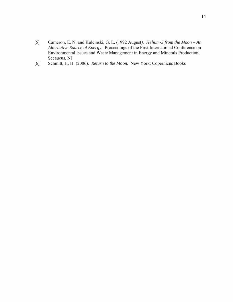
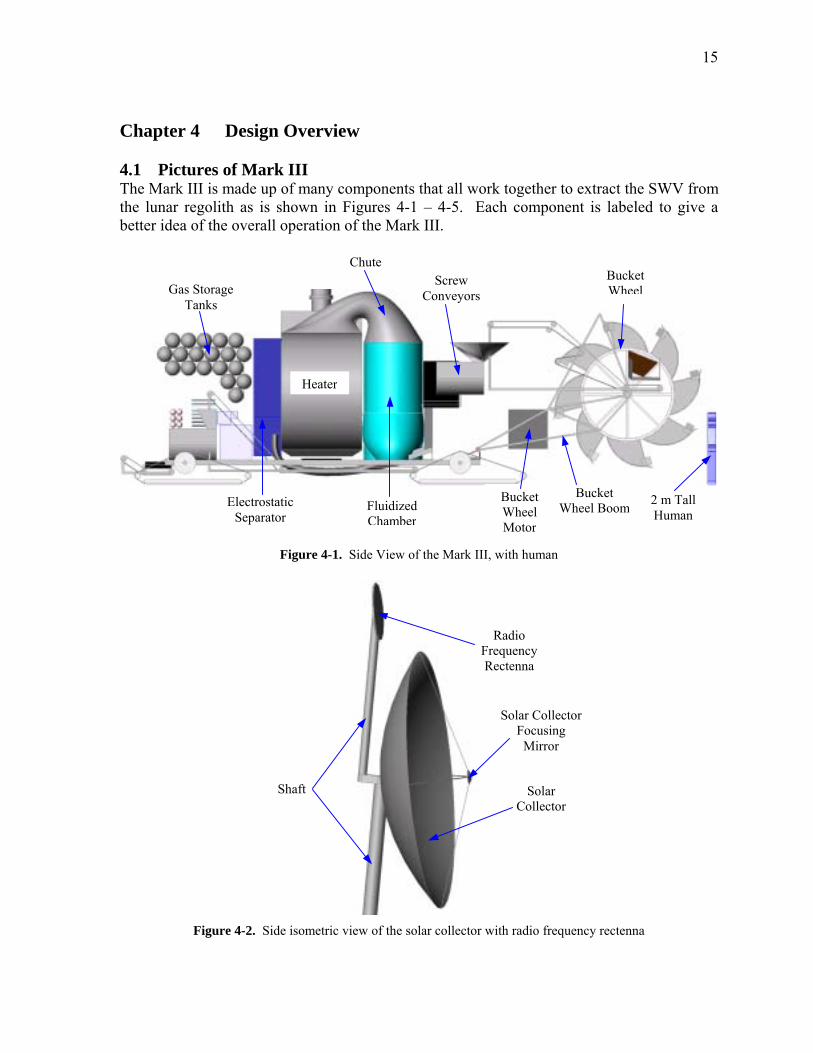
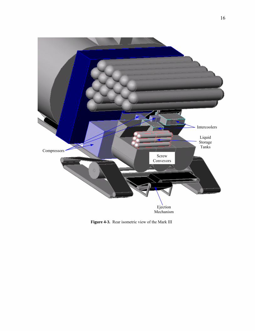
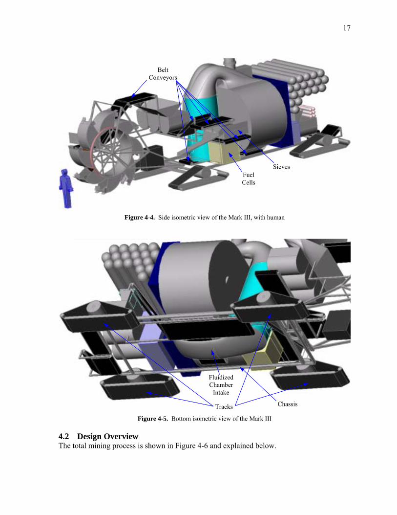
Chapter 4 Design Overview 4.1 Pictures of Mark III The Mark III is made up of many components that all work together to extract the SWV from the lunar regolith as is shown in Figures 4-1 � 4-5. Each component is labeled to give a better idea of the overall operation of the Mark III.
Chute Screw
ConveyorsGas Storage Tanks
Electrostatic Separator
W 2 m Tall Human
Figure 4-1. Si
t
Figure 4-2. Side isometric vie
Fluidized Chamber
de View of the Mark III,
FR
w of the solar collector w
Bucket Wheel Motor
with human
Solar Collector Focusing
Mirror
C
ith radio frequency
BucketWheel
Heater
Bucket heel Boom
Shaf
Radio requencyectenna
Solar ollector
rectenna
16
Compressors
C s
Intercoolers
Liquid Storage Tanks
M
Figure 4-3. Rear isometric view of th
Screw onveyor
Ejection echanism
e Mark III
17
Belt Conveyors
Fuel Cells
Sieves
Figure 4-4. Side isometric view of the Mark III, with human
Fluidized Chamber
Intake
Chassis Tracks Figure 4-5. Bottom isometric view of the Mark III
4.2 Design Overview The total mining process is shown in Figure 4-6 and explained below.
18
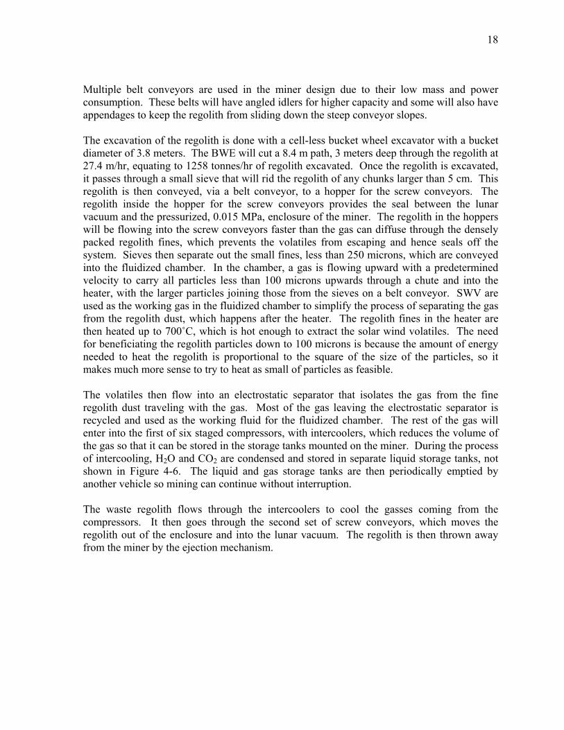
Multiple belt conveyors are used in the miner design due to their low mass and power consumption. These belts will have angled idlers for higher capacity and some will also have appendages to keep the regolith from sliding down the steep conveyor slopes. The excavation of the regolith is done with a cell-less bucket wheel excavator with a bucket diameter of 3.8 meters. The BWE will cut a 8.4 m path, 3 meters deep through the regolith at 27.4 m/hr, equating to 1258 tonnes/hr of regolith excavated. Once the regolith is excavated, it passes through a small sieve that will rid the regolith of any chunks larger than 5 cm. This regolith is then conveyed, via a belt conveyor, to a hopper for the screw conveyors. The regolith inside the hopper for the screw conveyors provides the seal between the lunar vacuum and the pressurized, 0.015 MPa, enclosure of the miner. The regolith in the hoppers will be flowing into the screw conveyors faster than the gas can diffuse through the densely packed regolith fines, which prevents the volatiles from escaping and hence seals off the system. Sieves then separate out the small fines, less than 250 microns, which are conveyed into the fluidized chamber. In the chamber, a gas is flowing upward with a predetermined velocity to carry all particles less than 100 microns upwards through a chute and into the heater, with the larger particles joining those from the sieves on a belt conveyor. SWV are used as the working gas in the fluidized chamber to simplify the process of separating the gas from the regolith dust, which happens after the heater. The regolith fines in the heater are then heated up to 700ûC, which is hot enough to extract the solar wind volatiles. The need for beneficiating the regolith particles down to 100 microns is because the amount of energy needed to heat the regolith is proportional to the square of the size of the particles, so it makes much more sense to try to heat as small of particles as feasible. The volatiles then flow into an electrostatic separator that isolates the gas from the fine regolith dust traveling with the gas. Most of the gas leaving the electrostatic separator is recycled and used as the working fluid for the fluidized chamber. The rest of the gas will enter into the first of six staged compressors, with intercoolers, which reduces the volume of the gas so that it can be stored in the storage tanks mounted on the miner. During the process of intercooling, H2O and CO2 are condensed and stored in separate liquid storage tanks, not shown in Figure 4-6. The liquid and gas storage tanks are then periodically emptied by another vehicle so mining can continue without interruption. The waste regolith flows through the intercoolers to cool the gasses coming from the compressors. It then goes through the second set of screw conveyors, which moves the regolith out of the enclosure and into the lunar vacuum. The regolith is then thrown away from the miner by the ejection mechanism.
19
Figure 4-6. Processing schematic for the regolith and evolved gasses
Hea
ter
Bel
t C
onve
yors
SWV
Elec
trost
atic
Se
para
tor
Slid
es
Unp
roce
ssed
R
egol
ith
Chu
te
Inte
rcoo
lers
Gas
Sto
rage
Ta
nks
Was
te
Reg
olith
BW
E
Scre
w
Con
veyo
rs
Ejec
tion
Mec
hani
sm
Scre
w
Con
veyo
rs
Com
pres
sors
Fl
uidi
zed
Cha
mbe
r Siev
es
Encl
osur
e 0.
015
MPa
Vac
uum
Figu
re 4
-6.
Proc
essi
ng sc
hem
atic
for t
he re
golit
h an
d ev
olve
d ga
sses
Reg
olith
Pro
cess
ing
Sche
mat
ic
20
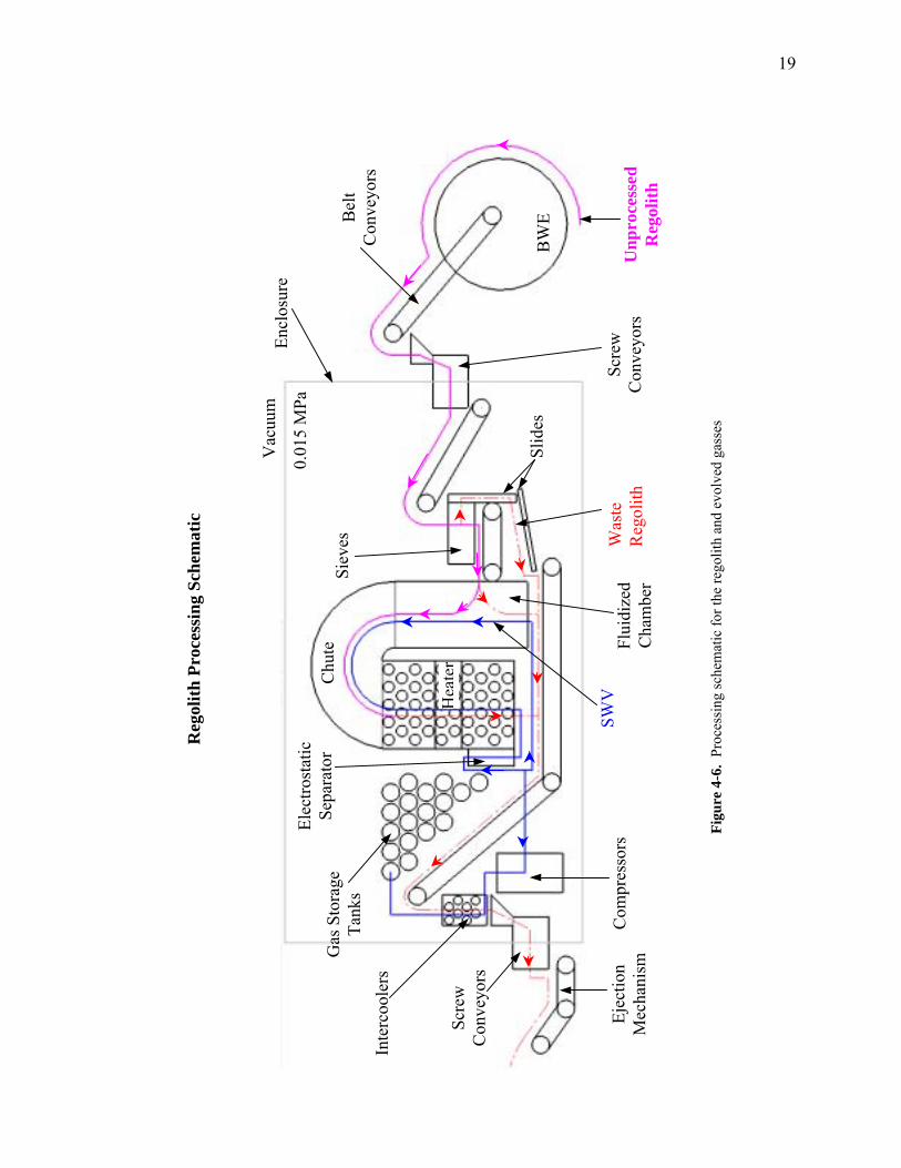
The energy for the heater comes from concentrated sunlight. To concentrate the sunlight to get the 12.3 MW needed for the heater, two parabolic dishes are used. The first is a large stationary dish that 1) collects, 2) concentrates, and 3) redirects the suns rays to 4) the solar collector on top of the miner, shown in Figure 4-7. Figure 4-8 shows that the solar collector on the miner 5) collects, 6) concentrates, and 7) redirects the now concentrated solar beam into 8) the heater, where it is used to heat the working fluid which in turn heats the regolith.
Incoming Sunlight
Mirrors
Stationary Parabolic Dish
Shaft
Concentrated Beam
Solar Collector on Miner (see Figure 4-8)
4
1 � 3 km
1
3 2
Focusing Mirror
Figure 4-7. Process of concentrating and redirecting the sunlight into the miner heater (not to scale)
Focusing Mirror
Shaft
Further Concentrated Beam
Mirror
8
5
76
Parabolic Dish Concentrated
Beam
Miner Heater Mark III
Figure 4-8. Enlarged side view of the solar collector on the miner for the sunlight concentrating process (not to scale)
Both the stationary dish and the solar collector use a similar process, see Figure 4-9, to concentrate the light. If a light beam strikes a parabolic mirror perpendicular to the projected

21
area, it will be redirected through the focus of the mirror. Conversely, if a beam of light travels through the focus of a parabolic mirror and strikes the mirror, it will be redirected in a direction perpendicular to the projected area of the mirror. So by placing the focus of the smaller parabolic mirror at the focus of the larger dish and aligning the two parabolic dishes to be facing eachother, 9) the incoming light will be 10) redirected through the focus of both mirrors and then be 11) redirected again perpendicular to the refocusing dish and 12) through the center of the parabolic collector dish.
10
11 Focus of Both
Parabolic Dishes
Parabolic Refocusing
Dish
Incoming Light
9Parabolic Collector
Dish
Concentrated Outgoing
Light
12
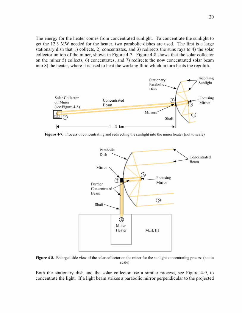
Figure 4-9. Side view of the optics for solar collector and stationary collector dishes Although Figures 4-6 � 4-8 show that the beams from the large stationary dish travel in a straight line to the solar collector on the miner, this is not quite the case. White light cannot be perfectly beamed in a straight line due to dispersion. To keep the light highly concentrated, it will be slightly focused when traveling from the large stationary dish to the solar collector on the Mark III. This makes the problem much more difficult due to the fact that the distance between the miner and the stationary dish will be constantly changing, so the focus of the concentrated light must also be constantly changing. This will involve highly complicated optics on the stationary dish and is not covered in this thesis. This focusing of the beam will not adversely affect the optics on the solar collector mounted on the Mark III. This is because the large stationary dish will be placed at least 1 km away from any mining site. This will keep the angle of the incident beams nearly perpendicular and allow the optics to function correctly, with a negligible amount of light being lost. An overview of the mine site and base camp is shown Figure 4-10. The mirrors on the large stationary dish are not directly behind the dish, as shown in Figure 4-7, since, for certain situations, there would be no way to redirect the concentrated beam to
22
the Mark III. Such would be the case if the sunlight was coming from the left side of Figure 4-7. The stationary dish would be pointed towards the miner and have no way to redirect the beam. Two mirrors will be required to redirect the concentrated beam to the Mark III. One of these mirrors will be a few meters behind the dish, and the second will be mounted on a shaft above the dish. This will allow for easy redirection no matter where the sun is relevant to the Mark III.
Minimum Distance for Solar Collector
Beam (1 km Radius)
PV Cells
Future Mine Site
Previously Mined Area
Current Mine Site
Miner
Stationary Solar Collector System and RF Antenna
Maximum Distance for RF Beam (3 km
Radius)
10 km, at Most
Base Camp: Support
Facilities and Habitats
Figure 4-10. Overview of mine site and support facilities (not to scale) Both the stationary dish and the solar collector will be able to rotate about two axes. The first will allow the dishes to tilt up and down, with the second allowing them to spin about their shaft axes. This allows the stationary dish to track the sun and the solar collector to track the stationary dish. In addition to this, the stationary dish will also have rotating mirror that will allow it to track the miner. The power for the miner will be provided via microwave, or RF beaming. This system is similar to the solar collector system, with a collection rectenna on the mark III and a large stationary antenna mounted above the large stationary solar collector, between 1 � 3 km away from the mine, shown in Figure 4-10. Power for the large RF antenna comes from an array of photovoltaic (PV) cells. The antenna uses integrated circuits to convert the DC power to RF and send a RF beam to the Mark III. On the Mark III, there will be a rectenna
23
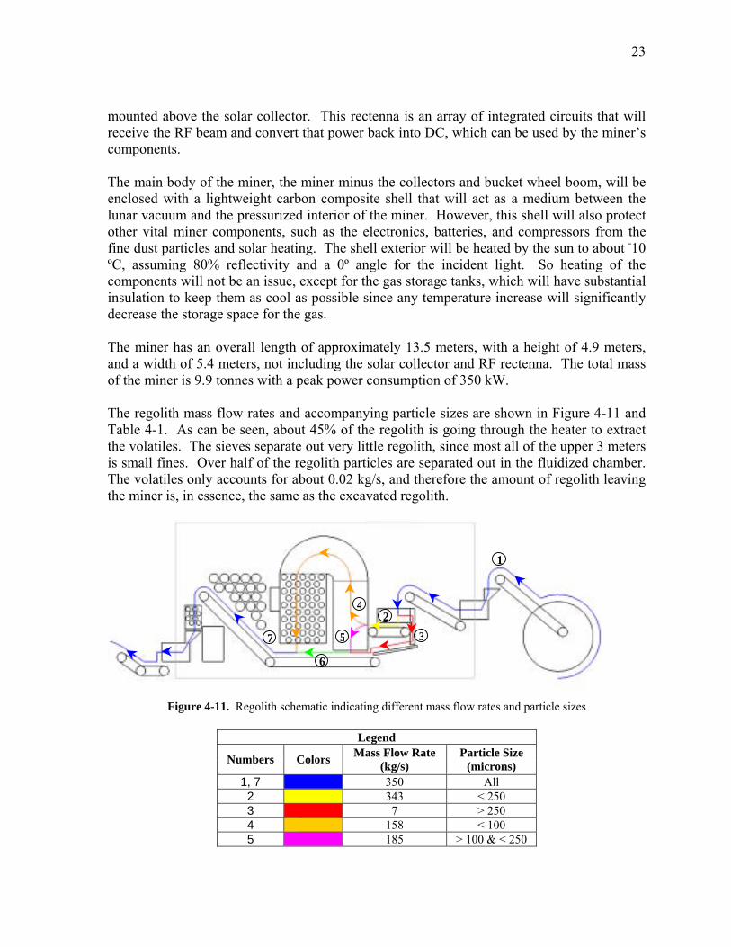
mounted above the solar collector. This rectenna is an array of integrated circuits that will receive the RF beam and convert that power back into DC, which can be used by the miner�s components. The main body of the miner, the miner minus the collectors and bucket wheel boom, will be enclosed with a lightweight carbon composite shell that will act as a medium between the lunar vacuum and the pressurized interior of the miner. However, this shell will also protect other vital miner components, such as the electronics, batteries, and compressors from the fine dust particles and solar heating. The shell exterior will be heated by the sun to about -10 ºC, assuming 80% reflectivity and a 0º angle for the incident light. So heating of the components will not be an issue, except for the gas storage tanks, which will have substantial insulation to keep them as cool as possible since any temperature increase will significantly decrease the storage space for the gas. The miner has an overall length of approximately 13.5 meters, with a height of 4.9 meters, and a width of 5.4 meters, not including the solar collector and RF rectenna. The total mass of the miner is 9.9 tonnes with a peak power consumption of 350 kW. The regolith mass flow rates and accompanying particle sizes are shown in Figure 4-11 and Table 4-1. As can be seen, about 45% of the regolith is going through the heater to extract the volatiles. The sieves separate out very little regolith, since most all of the upper 3 meters is small fines. Over half of the regolith particles are separated out in the fluidized chamber. The volatiles only accounts for about 0.02 kg/s, and therefore the amount of regolith leaving the miner is, in essence, the same as the excavated regolith.
1
42
357
6
Figure 4-11. Regolith schematic indicating different mass flow rates and particle sizes
Legend
Numbers Colors Mass Flow Rate (kg/s)
Particle Size (microns)
1, 7 350 All 2 343 < 250 3 7 > 250 4 158 < 100 5 185 > 100 & < 250
24
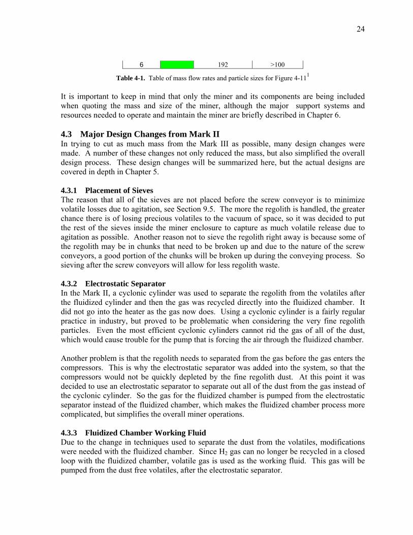
6 192 >100
Table 4-1. Table of mass flow rates and particle sizes for Figure 4-111 It is important to keep in mind that only the miner and its components are being included when quoting the mass and size of the miner, although the major support systems and resources needed to operate and maintain the miner are briefly described in Chapter 6. 4.3 Major Design Changes from Mark II In trying to cut as much mass from the Mark III as possible, many design changes were made. A number of these changes not only reduced the mass, but also simplified the overall design process. These design changes will be summarized here, but the actual designs are covered in depth in Chapter 5. 4.3.1 Placement of Sieves The reason that all of the sieves are not placed before the screw conveyor is to minimize volatile losses due to agitation, see Section 9.5. The more the regolith is handled, the greater chance there is of losing precious volatiles to the vacuum of space, so it was decided to put the rest of the sieves inside the miner enclosure to capture as much volatile release due to agitation as possible. Another reason not to sieve the regolith right away is because some of the regolith may be in chunks that need to be broken up and due to the nature of the screw conveyors, a good portion of the chunks will be broken up during the conveying process. So sieving after the screw conveyors will allow for less regolith waste. 4.3.2 Electrostatic Separator In the Mark II, a cyclonic cylinder was used to separate the regolith from the volatiles after the fluidized cylinder and then the gas was recycled directly into the fluidized chamber. It did not go into the heater as the gas now does. Using a cyclonic cylinder is a fairly regular practice in industry, but proved to be problematic when considering the very fine regolith particles. Even the most efficient cyclonic cylinders cannot rid the gas of all of the dust, which would cause trouble for the pump that is forcing the air through the fluidized chamber. Another problem is that the regolith needs to separated from the gas before the gas enters the compressors. This is why the electrostatic separator was added into the system, so that the compressors would not be quickly depleted by the fine regolith dust. At this point it was decided to use an electrostatic separator to separate out all of the dust from the gas instead of the cyclonic cylinder. So the gas for the fluidized chamber is pumped from the electrostatic separator instead of the fluidized chamber, which makes the fluidized chamber process more complicated, but simplifies the overall miner operations. 4.3.3 Fluidized Chamber Working Fluid Due to the change in techniques used to separate the dust from the volatiles, modifications were needed with the fluidized chamber. Since H2 gas can no longer be recycled in a closed loop with the fluidized chamber, volatile gas is used as the working fluid. This gas will be pumped from the dust free volatiles, after the electrostatic separator.
25
4.3.4 Hydrogen Separation In the Mark III, the separation of H2 using palladium membranes will not be done on the miner. This will instead be done later at the cryogenic separation facility. Separating the H2 on the miner only complicates the process. It will be much easier to do at the separation facility, where there will not be as much of an emphasis on power and mass requirements. This also simplifies the process of getting the volatiles from the Mark III to the base camp, since only one set of gas storage tanks will be needed, instead of the two sets needed for the Mark II. 4.3.5 Locomotion With some quick calculations, it is easy to see that the mass of the Mark III when loaded with regolith is too much for wheels to support, see Section 5.14. The miner would literally sink into the regolith without a larger footprint, so the four wheels were replaced by four tracks, each with a contact area of about 1.3 m2, which is enough to keep the Mark III from settling too deep into the regolith. 4.3.6 Bucket Wheel Excavator To enable the Mark III to cut to a depth of 3 meters, the bucket wheel excavator will be able to move up and down, a capability not seen on the Mark II. This ability also helps in decreasing the size of the bucket wheel, since it no longer needs to be able to cut to a depth of 3 meters in one slice as was done on the Mark II. Instead the bucket wheel is smaller and will take multiple cuts to get to a depth of 3 meters. Actually, with the ability of the bucket wheel to move up and down, the Mark III can dig much deeper than 3 meters if wanted. So if it was found that there was an area of regolith 10 meters in depth, the Mark III would be able to mine this area, with the main constraint being the ability of the Mark III to get the waste regolith out of the mine. But for this thesis, it will be assumed that the Mark III will only dig to a depth of 3 meters. 4.3.7 Electric Power Source The electric power source has been changed from PV mounted around the edge of the solar collector to beamed RF energy waves. The problem with PV cells is that the radiator needed to keep the cells below 100 ºC would need to be 1100 m2. So the electric power on the Mark III will instead be provided from RF beaming. 4.4 References [1] Sviatoslavsky, I.N. and Jacobs, M. (1988). Mobile Helium-3 Mining and Extraction
System and its Benefits Toward Lunar Base Self-Sufficiency (WCSAR-TR-AR3-8808-1). Madison, WI: Wisconsin Center for Space Automation and Robotics
26
Chapter 5 Mark III Components The Mark III consists of many different components that use a variety of materials; the properties of these materials are indexed in Appendix B. 5.1 Bucket Wheel There are few machines capable of continuously excavating large amount of material, and out of all of them, there is one that stands above, the bucket wheel excavator. So, the Mark III uses a BWE for digging up the regolith. The bucket wheel on the Mark III is only 4 meters in diameter, whereas any other industry bucket wheel is on the order of tens of meters. 5.1.1 Digging Process The digging is done with the teeth on the front and side of each bucket. While the buckets are rotating around the wheel, the boom supporting the bucket wheel is slewing sideways. It is this sideways motion that digs into the regolith and fills up the buckets. The bucket wheel can also be moved up and down to allow the Mark III to dig to a depth of 3 meters. The cut height of BWE�s is about half of the diameter of the bucket wheel, so 2 meters in this case. To cut to a depth of 3 meters, the bucket wheel must be raised and lowered, since a bucket wheel diameter of 6 meters is too large for this design. Once to a depth of 3 meters, the miner will dig out the regolith starting with the top layer. It will slew from one side to the other in a 90º arc and then drop down for the next cut. After the bucket reaches a depth of 3 meters, the miner will move forward for the next cut. When the miner gets to a new mining site, it will first need to get to a depth of 3 meters. To do this, the bucket wheel will need to cut below the surface level. Once the miner is on the decline towards the desired depth, the mining will continue normally until a depth of 3 meters is reached, at which point the buckets will be raised to level off mining at the desired depth. Normal bucket wheel excavators do not just move the boom from side to side, instead the whole machine rotates with the boom. It was decided that this would be a hindrance to the Mark III design since the miner will be carving out a much narrower path when first descending into the regolith and would require a large roller bearing to support the entire weight of the miner, which could be troublesome with all of the dust prevalent on the lunar surface. This roller bearing would also raise the center of gravity of the miner, thereby decreasing the stability. Another difference is that the boom on the Mark III will not sweep out a 180û arc that many bucket wheel excavators can, instead it will sweep through an angle of 90û due to clearance issues between the boom and the rest of the miner. The bucket wheel boom will have a torque motor that will slew the boom from side to side with a power winch used to raise and lower the boom. 5.1.2 Challenges - Rocks One challenge in mining the moon will be in deciding where to mine so that the bucket wheel will not encounter any large rocks that could potentially damage the buckets, bucket wheel, boom, motor, or any other part of the miner. The first step in avoiding rocks will be in the
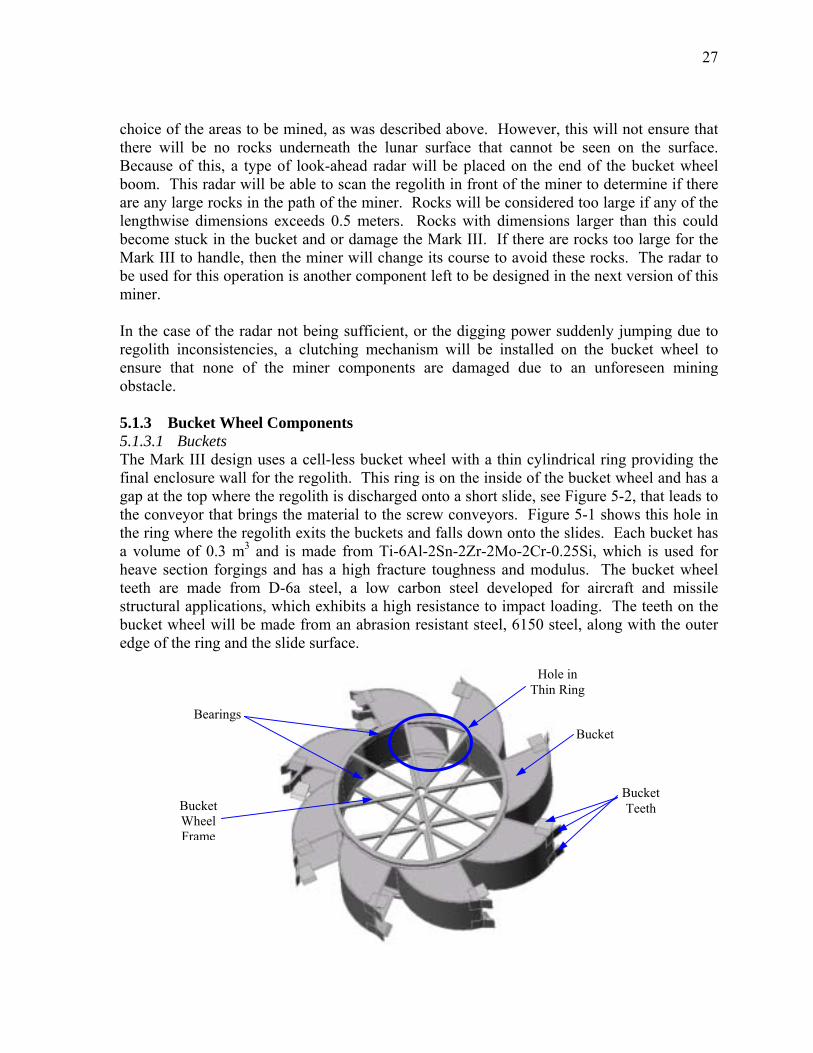
27
choice of the areas to be mined, as was described above. However, this will not ensure that there will be no rocks underneath the lunar surface that cannot be seen on the surface. Because of this, a type of look-ahead radar will be placed on the end of the bucket wheel boom. This radar will be able to scan the regolith in front of the miner to determine if there are any large rocks in the path of the miner. Rocks will be considered too large if any of the lengthwise dimensions exceeds 0.5 meters. Rocks with dimensions larger than this could become stuck in the bucket and or damage the Mark III. If there are rocks too large for the Mark III to handle, then the miner will change its course to avoid these rocks. The radar to be used for this operation is another component left to be designed in the next version of this miner. In the case of the radar not being sufficient, or the digging power suddenly jumping due to regolith inconsistencies, a clutching mechanism will be installed on the bucket wheel to ensure that none of the miner components are damaged due to an unforeseen mining obstacle. 5.1.3 Bucket Wheel Components 5.1.3.1 Buckets The Mark III design uses a cell-less bucket wheel with a thin cylindrical ring providing the final enclosure wall for the regolith. This ring is on the inside of the bucket wheel and has a gap at the top where the regolith is discharged onto a short slide, see Figure 5-2, that leads to the conveyor that brings the material to the screw conveyors. Figure 5-1 shows this hole in the ring where the regolith exits the buckets and falls down onto the slides. Each bucket has a volume of 0.3 m3 and is made from Ti-6Al-2Sn-2Zr-2Mo-2Cr-0.25Si, which is used for heave section forgings and has a high fracture toughness and modulus. The bucket wheel teeth are made from D-6a steel, a low carbon steel developed for aircraft and missile structural applications, which exhibits a high resistance to impact loading. The teeth on the bucket wheel will be made from an abrasion resistant steel, 6150 steel, along with the outer edge of the ring and the slide surface.
Hole in Thin Ring
Bearings
Bucket Wheel Frame
Bucket
Bucket Teeth
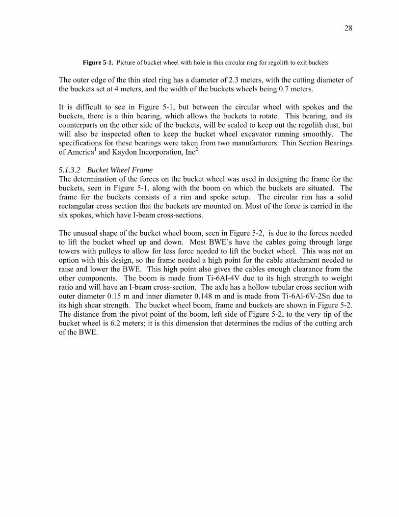
28
Figure 5-1. Picture of bucket wheel with hole in thin circular ring for regolith to exit buckets The outer edge of the thin steel ring has a diameter of 2.3 meters, with the cutting diameter of the buckets set at 4 meters, and the width of the buckets wheels being 0.7 meters. It is difficult to see in Figure 5-1, but between the circular wheel with spokes and the buckets, there is a thin bearing, which allows the buckets to rotate. This bearing, and its counterparts on the other side of the buckets, will be sealed to keep out the regolith dust, but will also be inspected often to keep the bucket wheel excavator running smoothly. The specifications for these bearings were taken from two manufacturers: Thin Section Bearings of America1 and Kaydon Incorporation, Inc2. 5.1.3.2 Bucket Wheel Frame The determination of the forces on the bucket wheel was used in designing the frame for the buckets, seen in Figure 5-1, along with the boom on which the buckets are situated. The frame for the buckets consists of a rim and spoke setup. The circular rim has a solid rectangular cross section that the buckets are mounted on. Most of the force is carried in the six spokes, which have I-beam cross-sections. The unusual shape of the bucket wheel boom, seen in Figure 5-2, is due to the forces needed to lift the bucket wheel up and down. Most BWE�s have the cables going through large towers with pulleys to allow for less force needed to lift the bucket wheel. This was not an option with this design, so the frame needed a high point for the cable attachment needed to raise and lower the BWE. This high point also gives the cables enough clearance from the other components. The boom is made from Ti-6Al-4V due to its high strength to weight ratio and will have an I-beam cross-section. The axle has a hollow tubular cross section with outer diameter 0.15 m and inner diameter 0.148 m and is made from Ti-6Al-6V-2Sn due to its high shear strength. The bucket wheel boom, frame and buckets are shown in Figure 5-2. The distance from the pivot point of the boom, left side of Figure 5-2, to the very tip of the bucket wheel is 6.2 meters; it is this dimension that determines the radius of the cutting arch of the BWE.
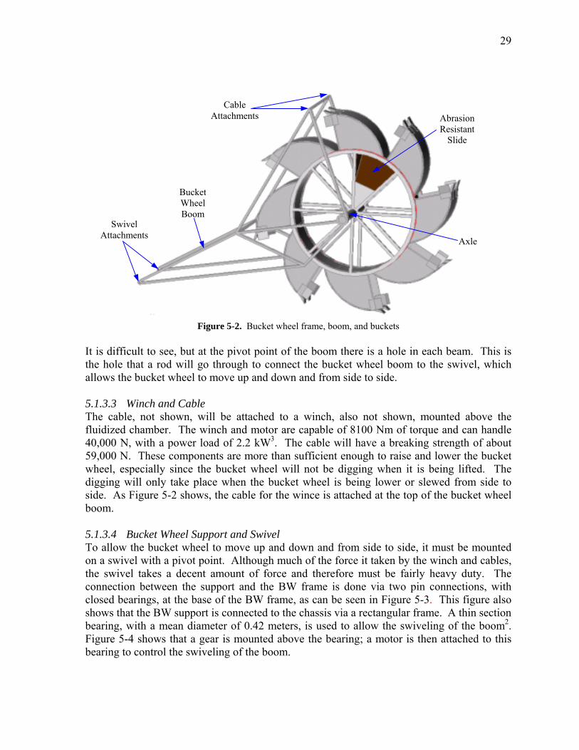
29
Cable Attachments
BucketWheel Boom
Swivel Attachments
Figure 5-2. Bucket wheel frame, boom, and buckets It is difficult to see, but at the pivot point of the boom there is a hole in eacthe hole that a rod will go through to connect the bucket wheel boom to thallows the bucket wheel to move up and down and from side to side. 5.1.3.3 Winch and Cable The cable, not shown, will be attached to a winch, also not shown, mofluidized chamber. The winch and motor are capable of 8100 Nm of torque40,000 N, with a power load of 2.2 kW3. The cable will have a breaking s59,000 N. These components are more than sufficient enough to raise and wheel, especially since the bucket wheel will not be digging when it is bdigging will only take place when the bucket wheel is being lower or slewside. As Figure 5-2 shows, the cable for the wince is attached at the top of tboom. 5.1.3.4 Bucket Wheel Support and Swivel To allow the bucket wheel to move up and down and from side to side, it mon a swivel with a pivot point. Although much of the force it taken by the wthe swivel takes a decent amount of force and therefore must be fairly hconnection between the support and the BW frame is done via two pin cclosed bearings, at the base of the BW frame, as can be seen in Figure 5-3. shows that the BW support is connected to the chassis via a rectangular frambearing, with a mean diameter of 0.42 meters, is used to allow the swivelinFigure 5-4 shows that a gear is mounted above the bearing; a motor is thenbearing to control the swiveling of the boom.
AbrasionResistant
Slide
Axle
h beam. This is e swivel, which
unted above the and can handle trength of about lower the bucket eing lifted. The ed from side to he bucket wheel
ust be mounted inch and cables, eavy duty. The onnections, with This figure also e. A thin section g of the boom2. attached to this
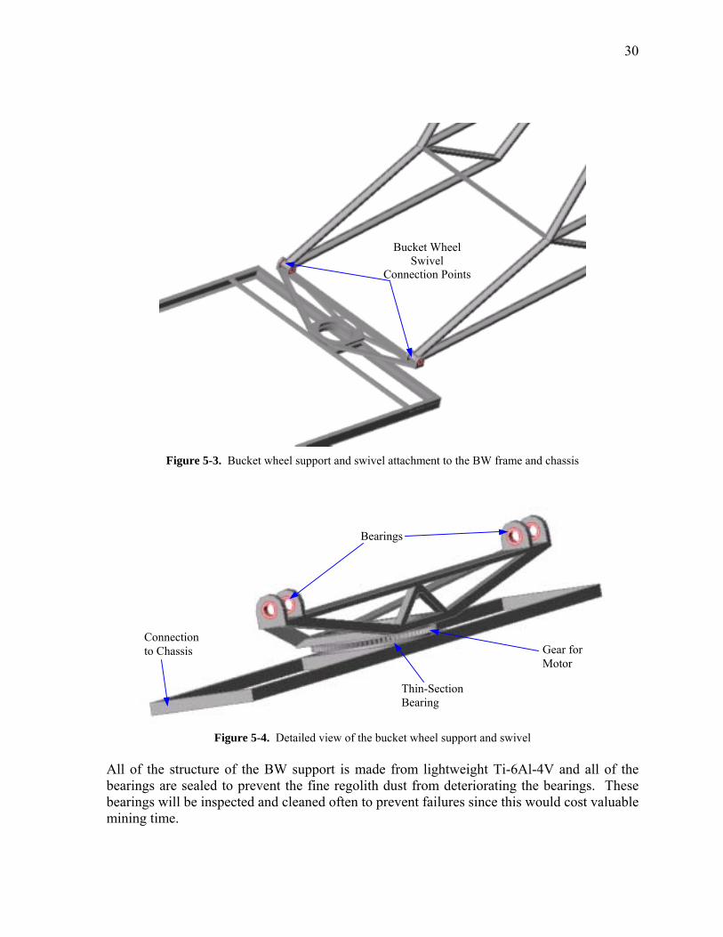
30
Bucket Wheel Swivel
Connection Points
Figure 5-3. Bucket wheel support and swivel attachment to the BW frame and chassis
Bearings
Connection to Chassis Gear for
Motor
Thin-Section Bearing
Figure 5-4. Detailed view of the bucket wheel support and swivel All of the structure of the BW support is made from lightweight Ti-6Al-4V and all of the bearings are sealed to prevent the fine regolith dust from deteriorating the bearings. These bearings will be inspected and cleaned often to prevent failures since this would cost valuable mining time.
31
5.1.3.5 Bucket Wheel Sieve Since it is possible to get rocks as large as 0.5 meters across into the buckets, there must be a way to filter these larger rocks out of the system before reaching the screw conveyors. If rocks this size got into the hopper for the screw conveyors, it could cause a clogging and/or a seal problem. To prevent this, the material leaving the buckets goes through a very course sieve, made from D-6a steel, before ending up on the conveyor belt leading to the screw conveyors. This sieve will filter out any regolith particles larger than 5 cm and drop them back onto the lunar surface. This is not the main set of sieves that begin the separation process, these sieves are only to protect the screw conveyors and ensure a tight seal 5.1.4 Bucket Wheel Masses Due to the complexity and number of parts, the bucket wheel excavator is one of the more massive components of the Mark III. In all, the bucket wheel excavator has a mass of about 1800 kg. Table 5-1 breaks this up into the individual components.
Bucket Wheel Excavator Masses (kg) Buckets 510
Bucket Wheel Frame 506 Bucket Wheel Boom 183 Bucket Wheel Motor 275
Bucket Wheel Support Bearing 6 Swivel Motor 56
Bucket Wheel Winch 135 Bucket Wheel Bearings 159
Bucket Wheel Sieve 6 Total 1836
Table 5-1. Component masses for the BWE The buckets and frame for the BWE are the most massive components due to the high torques and impact loads they must withstand. But, in general, the mass of the BWE is spread out over a number of heavy components, leading to the high mass of the overall system. 5.1.5 Calculations 5.1.5.1 Power and Forces There are a number of different methods used in calculating the power required to use a bucket wheel excavator and the forces acting on the bucket. Equations 5-1 � 5-7 show one possible method. This also happens to be the most straightforward method and the method used for this thesis. For the other methods, consult Rasper4, or other bucket wheel excavator design books. To calculate the digging force, Fdig, and lifting force, Flift, required to excavate the regolith and then lift it to where it exits the bucket. These calculations are done in equations 5-1 and 5-2, respectively.
RJAfF fxldig = [N] (5-1)
32
RJF flift βγ163.0= [N] (5-2)
Where Jf, the equivalent amount of disturbed regolith in each bucket, defined in equation 5-3, Ax is a non-physical, unitless constant defined by equation 5-4, fl is the specific cutting resistance in kg/cm, taken from Table 4.2 in Rasper4, R is the radius of the bucket wheel cutting circle [m], γ is the regolith density [kg/m3] , and β is the fraction of the bucket wheel radius that the material must be raised.
fI
J ff
η= [m3] (5-3)
+=
opt
Hm
optx
Hckc
Aαφα
π2100 (5-4)
Where I is the bucket volume [m3], ηf is the fraction of the bucket that is filled with regolith, f is the swell factor, αopt is the optimal slice depth ratio, and Hφ is the angle between the bottom and top of the sickle cut [rad]. With Fdig and Flift known, equation 5-5 is used to calculate the total power required for the excavating of the regolith.
( liftdigreq FFsP +=η1000
) [kW] (5-5)
The only other force needed to be calculated is the slewing force, Fslew, which is the force required to move the bucket wheel from side to side. The first step is to calculate the slewing speed, νslew, as can be done with equation 5-6. The slewing force is then calculated using equation 5-7.
RcftIs
slewmax
=ν [m/s] (5-6)
digdig
slewslew FF
νν
= [N] (5-7)
Where s is the number of bucket discharges per minute, η is the overall efficiency of the shaft, and υdig is the linear speed, at radius R, of the rotating buckets [m/s]. For the bucket wheel on the Mark III, the following parameters were used: fl = 60 kg/cm
33
R = 1.9 m γ = 1800 kg/m3 β = 1.3 I = 0.29 m3
f = 1.5 αopt = π/2 rad
Hφ = π/2 rad s = 40 Hz η = 95% υdig = 0.99 m/s Using the above parameters and equations 5-1 � 5-7, the power required to excavate the regolith was found to be 108 kW, with 95% of the power being used to dig up the regolith, with the digging force being 100 kN. The slewing power required is 8.7 kW, with a force of 30 kN. 5.1.5.2 Structural Analysis Due to the complexity of the bucket wheel frame and boom geometry, the structural analysis was done in ANSYS®,5. However, due to the complexity of the model, some difficulties were encountered. The biggest problem was that the boom could not be modeled with an I-beam for the cross-sectional area, since the mesh size for the model was larger than the educational version of ANSYS® would allow. So as a compromise, the cross sectional area was modeled as a rectangle with similar moments of inertia to the I-beam. With this replacement model, the forces found from the calculations done in Section 5.1.5.1 were applied to the model, with the results shown in Figures 5-5 and 5-6.
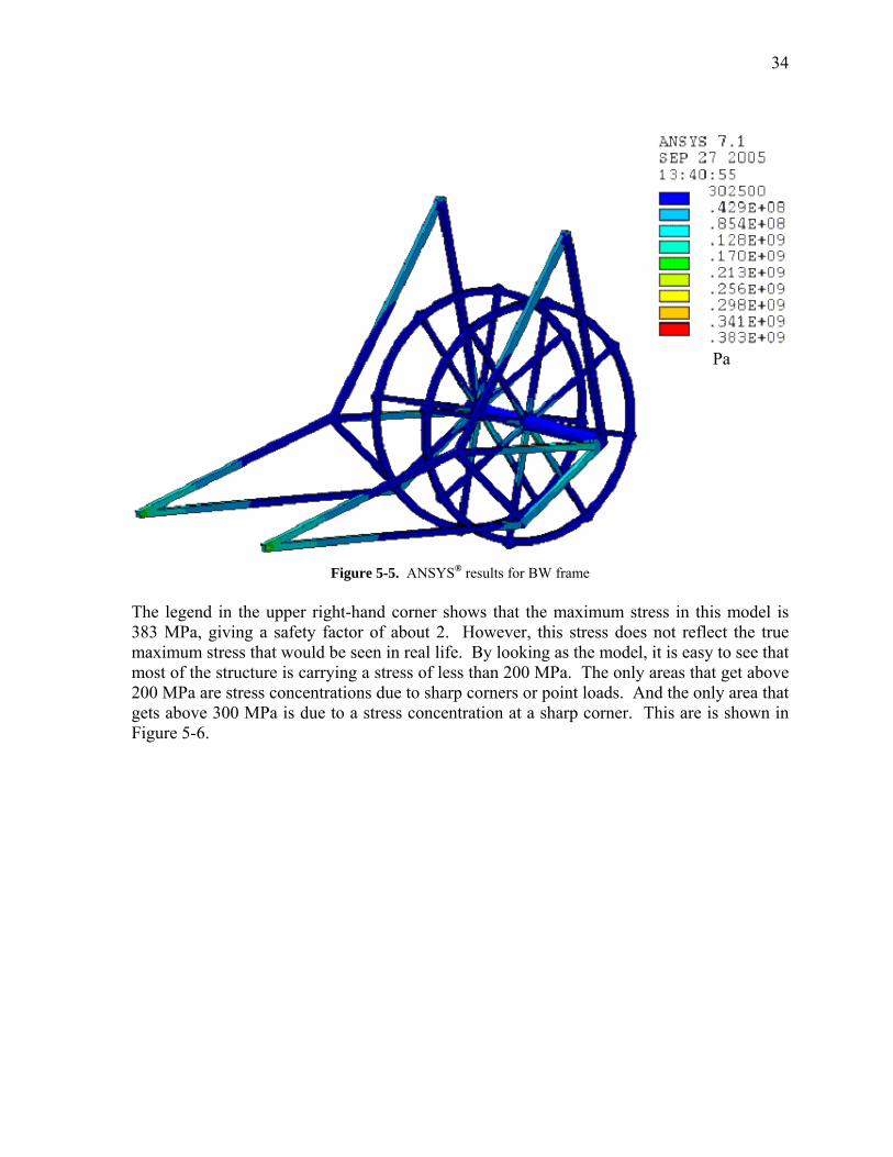
34
Pa
Figure 5-5. ANSYS® results for BW frame The legend in the upper right-hand corner shows that the maximum stress in this model is 383 MPa, giving a safety factor of about 2. However, this stress does not reflect the true maximum stress that would be seen in real life. By looking as the model, it is easy to see that most of the structure is carrying a stress of less than 200 MPa. The only areas that get above 200 MPa are stress concentrations due to sharp corners or point loads. And the only area that gets above 300 MPa is due to a stress concentration at a sharp corner. This are is shown in Figure 5-6.
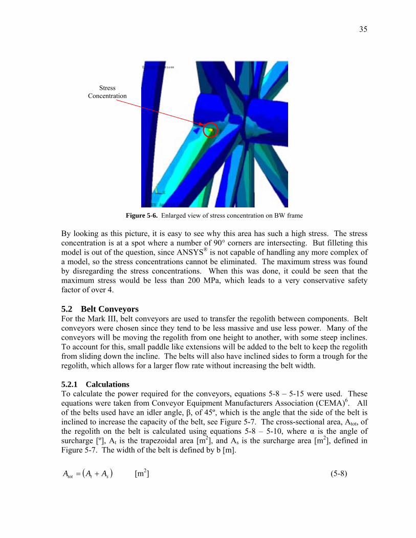
35
Stress Concentration
Figure 5-6. Enlarged view of stress concentration on BW frame By looking as this picture, it is easy to see why this area has such a high stress. The stress concentration is at a spot where a number of 90° corners are intersecting. But filleting this model is out of the question, since ANSYS® is not capable of handling any more complex of a model, so the stress concentrations cannot be eliminated. The maximum stress was found by disregarding the stress concentrations. When this was done, it could be seen that the maximum stress would be less than 200 MPa, which leads to a very conservative safety factor of over 4. 5.2 Belt Conveyors For the Mark III, belt conveyors are used to transfer the regolith between components. Belt conveyors were chosen since they tend to be less massive and use less power. Many of the conveyors will be moving the regolith from one height to another, with some steep inclines. To account for this, small paddle like extensions will be added to the belt to keep the regolith from sliding down the incline. The belts will also have inclined sides to form a trough for the regolith, which allows for a larger flow rate without increasing the belt width. 5.2.1 Calculations To calculate the power required for the conveyors, equations 5-8 � 5-15 were used. These equations were taken from Conveyor Equipment Manufacturers Association (CEMA)6. All of the belts used have an idler angle, β, of 45º, which is the angle that the side of the belt is inclined to increase the capacity of the belt, see Figure 5-7. The cross-sectional area, Atot, of the regolith on the belt is calculated using equations 5-8 � 5-10, where α is the angle of surcharge [º], At is the trapezoidal area [m2], and As is the surcharge area [m2], defined in Figure 5-7. The width of the belt is defined by b [m].
( sttot AAA += ) [m2] (5-8)
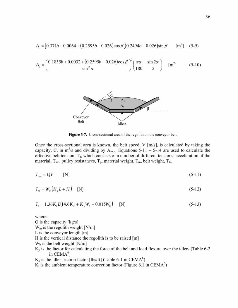
36
( )[ ]( ) ββ sin026.02494.0cos026.02595.00064.0371.0 −−++= bbbAt [m2] (5-9)
( )
−
−++
=22sin
180sincos026.02595.00032.01855.0 2
2
απαα
βbbAs [m2] (5-10)
At
Conveyor Belt
β
α
Idlers
As
Figure 5-7. Cross-sectional area of the regolith on the conveyor belt Once the cross-sectional area is known, the belt speed, V [m/s], is calculated by taking the capacity, C, in m3/s and dividing by Atot. Equations 5-11 � 5-14 are used to calculate the effective belt tension, Te, which consists of a number of different tensions: acceleration of the material, Tam, pulley resistances, Tp, material weight, Tm, belt weight, Tb.
QVTam = [N] (5-11)
( )HLKWT ymm += [N] (5-12)
( )bbyxtb WWKKLKT 015.06.1436.1 ++= [N] (5-13)
where: Q is the capacity [kg/s] Wm is the regolith weight [N/m] L is the conveyor length [m] H is the vertical distance the regolith is to be raised [m] Wb is the belt weight [N/m] Ky is the factor for calculating the force of the belt and load flexure over the idlers (Table 6-2
in CEMA6) Kx is the idler friction factor [lbs/ft] (Table 6-1 in CEMA6) Kt is the ambient temperature correction factor (Figure 6.1 in CEMA6)
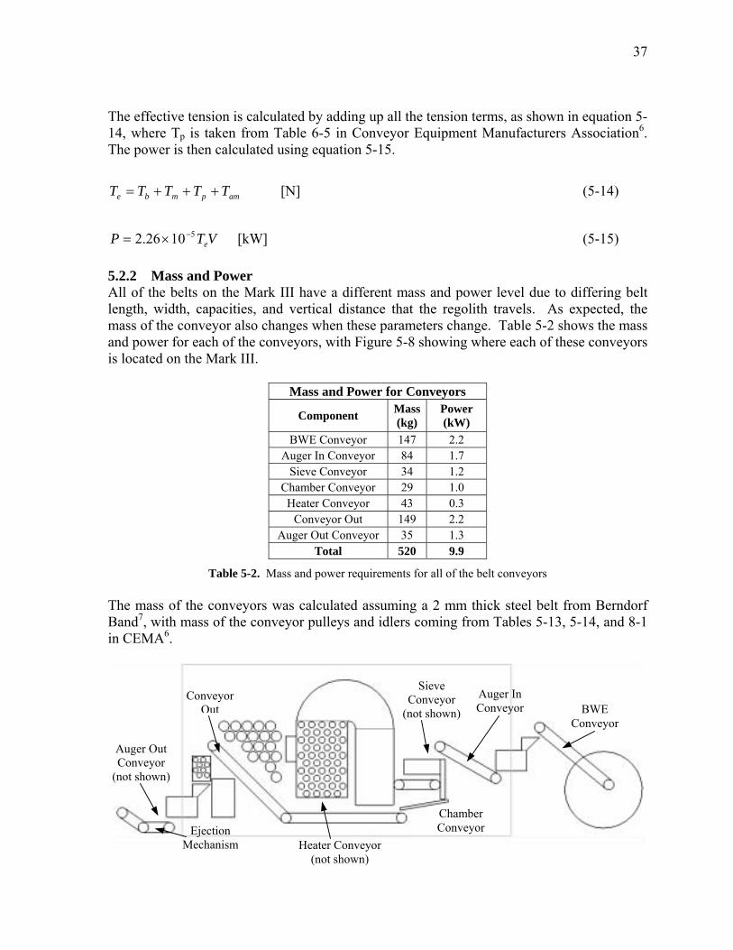
37
The effective tension is calculated by adding up all the tension terms, as shown in equation 5-14, where Tp is taken from Table 6-5 in Conveyor Equipment Manufacturers Association6. The power is then calculated using equation 5-15.
ampmbe TTTTT +++= [N] (5-14)
VTP e51026.2 −×= [kW] (5-15)
5.2.2 Mass and Power All of the belts on the Mark III have a different mass and power level due to differing belt length, width, capacities, and vertical distance that the regolith travels. As expected, the mass of the conveyor also changes when these parameters change. Table 5-2 shows the mass and power for each of the conveyors, with Figure 5-8 showing where each of these conveyors is located on the Mark III.
Mass and Power for Conveyors
Component Mass (kg)
Power (kW)
BWE Conveyor 147 2.2 Auger In Conveyor 84 1.7
Sieve Conveyor 34 1.2 Chamber Conveyor 29 1.0 Heater Conveyor 43 0.3
Conveyor Out 149 2.2 Auger Out Conveyor 35 1.3
Total 520 9.9
Table 5-2. Mass and power requirements for all of the belt conveyors The mass of the conveyors was calculated assuming a 2 mm thick steel belt from Berndorf Band7, with mass of the conveyor pulleys and idlers coming from Tables 5-13, 5-14, and 8-1 in CEMA6.
Sieve Conveyor
(not shown)Auger In Conveyor
BWE
Auger Out Conveyor
(not shown)
ConveyorOut
Conveyor
Chamber Conveyor
Heater Conveyor (not shown)
Ejection Mechanism
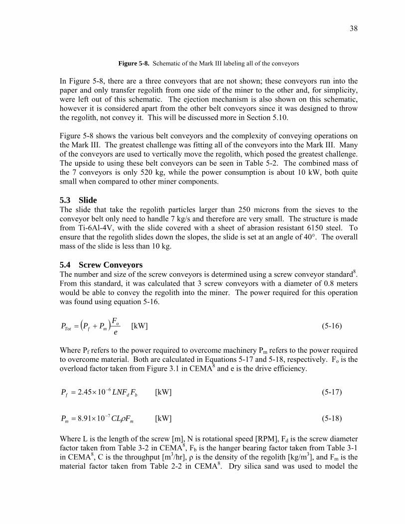
38
Figure 5-8. Schematic of the Mark III labeling all of the conveyors In Figure 5-8, there are a three conveyors that are not shown; these conveyors run into the paper and only transfer regolith from one side of the miner to the other and, for simplicity, were left out of this schematic. The ejection mechanism is also shown on this schematic, however it is considered apart from the other belt conveyors since it was designed to throw the regolith, not convey it. This will be discussed more in Section 5.10. Figure 5-8 shows the various belt conveyors and the complexity of conveying operations on the Mark III. The greatest challenge was fitting all of the conveyors into the Mark III. Many of the conveyors are used to vertically move the regolith, which posed the greatest challenge. The upside to using these belt conveyors can be seen in Table 5-2. The combined mass of the 7 conveyors is only 520 kg, while the power consumption is about 10 kW, both quite small when compared to other miner components. 5.3 Slide The slide that take the regolith particles larger than 250 microns from the sieves to the conveyor belt only need to handle 7 kg/s and therefore are very small. The structure is made from Ti-6Al-4V, with the slide covered with a sheet of abrasion resistant 6150 steel. To ensure that the regolith slides down the slopes, the slide is set at an angle of 40°. The overall mass of the slide is less than 10 kg. 5.4 Screw Conveyors The number and size of the screw conveyors is determined using a screw conveyor standard8. From this standard, it was calculated that 3 screw conveyors with a diameter of 0.8 meters would be able to convey the regolith into the miner. The power required for this operation was found using equation 5-16.
( )e
FPPP o
mfTot += [kW] (5-16)
Where Pf refers to the power required to overcome machinery Pm refers to the power required to overcome material. Both are calculated in Equations 5-17 and 5-18, respectively. Fo is the overload factor taken from Figure 3.1 in CEMA8 and e is the drive efficiency.
bdf FLNFP 61045.2 −×= [kW] (5-17)
mm FCLP ρ71091.8 −×= [kW] (5-18)
Where L is the length of the screw [m], N is rotational speed [RPM], Fd is the screw diameter factor taken from Table 3-2 in CEMA8, Fb is the hanger bearing factor taken from Table 3-1 in CEMA8, C is the throughput [m3/hr], ρ is the density of the regolith [kg/m3], and Fm is the material factor taken from Table 2-2 in CEMA8. Dry silica sand was used to model the
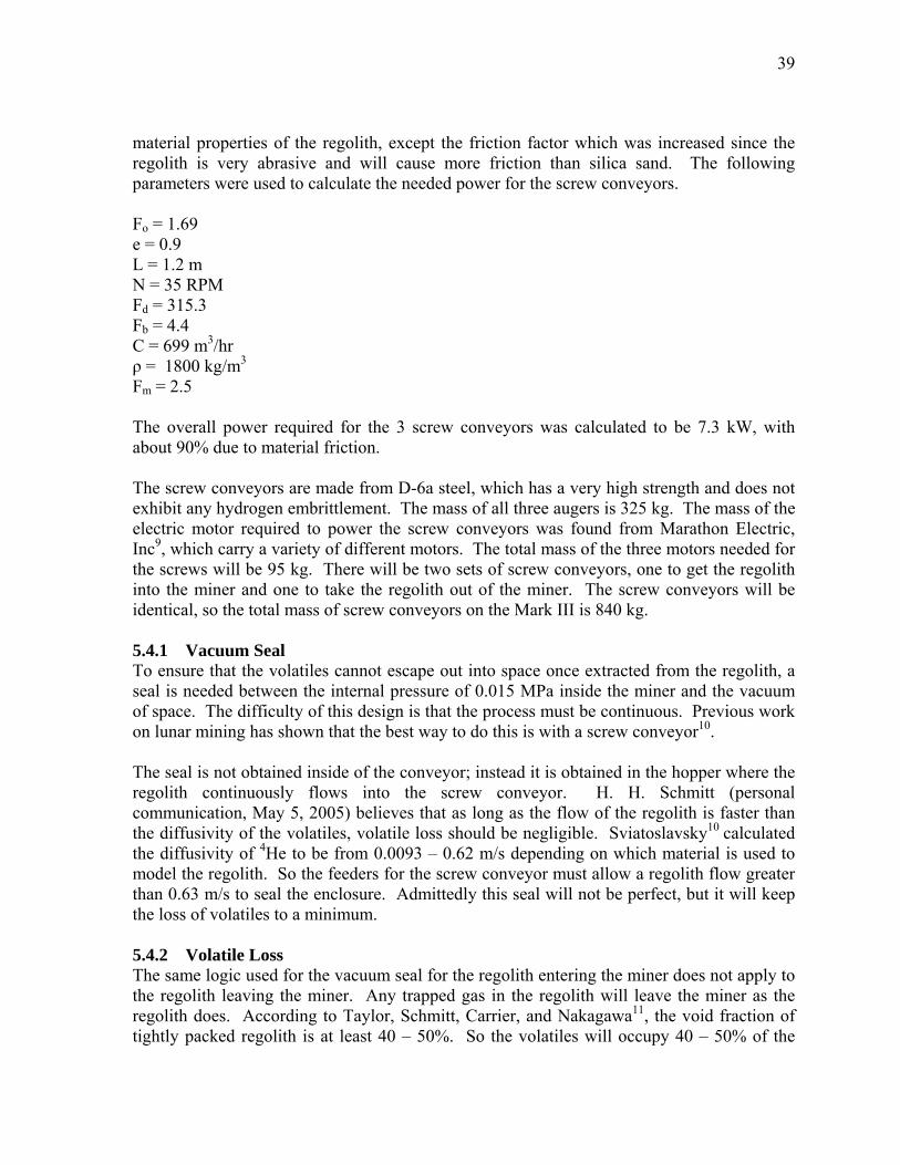
39
material properties of the regolith, except the friction factor which was increased since the regolith is very abrasive and will cause more friction than silica sand. The following parameters were used to calculate the needed power for the screw conveyors. Fo = 1.69 e = 0.9 L = 1.2 m N = 35 RPM Fd = 315.3 Fb = 4.4 C = 699 m3/hr ρ = 1800 kg/m3 Fm = 2.5 The overall power required for the 3 screw conveyors was calculated to be 7.3 kW, with about 90% due to material friction. The screw conveyors are made from D-6a steel, which has a very high strength and does not exhibit any hydrogen embrittlement. The mass of all three augers is 325 kg. The mass of the electric motor required to power the screw conveyors was found from Marathon Electric, Inc9, which carry a variety of different motors. The total mass of the three motors needed for the screws will be 95 kg. There will be two sets of screw conveyors, one to get the regolith into the miner and one to take the regolith out of the miner. The screw conveyors will be identical, so the total mass of screw conveyors on the Mark III is 840 kg. 5.4.1 Vacuum Seal To ensure that the volatiles cannot escape out into space once extracted from the regolith, a seal is needed between the internal pressure of 0.015 MPa inside the miner and the vacuum of space. The difficulty of this design is that the process must be continuous. Previous work on lunar mining has shown that the best way to do this is with a screw conveyor10. The seal is not obtained inside of the conveyor; instead it is obtained in the hopper where the regolith continuously flows into the screw conveyor. H. H. Schmitt (personal communication, May 5, 2005) believes that as long as the flow of the regolith is faster than the diffusivity of the volatiles, volatile loss should be negligible. Sviatoslavsky10 calculated the diffusivity of 4He to be from 0.0093 � 0.62 m/s depending on which material is used to model the regolith. So the feeders for the screw conveyor must allow a regolith flow greater than 0.63 m/s to seal the enclosure. Admittedly this seal will not be perfect, but it will keep the loss of volatiles to a minimum. 5.4.2 Volatile Loss The same logic used for the vacuum seal for the regolith entering the miner does not apply to the regolith leaving the miner. Any trapped gas in the regolith will leave the miner as the regolith does. According to Taylor, Schmitt, Carrier, and Nakagawa11, the void fraction of tightly packed regolith is at least 40 � 50%. So the volatiles will occupy 40 � 50% of the
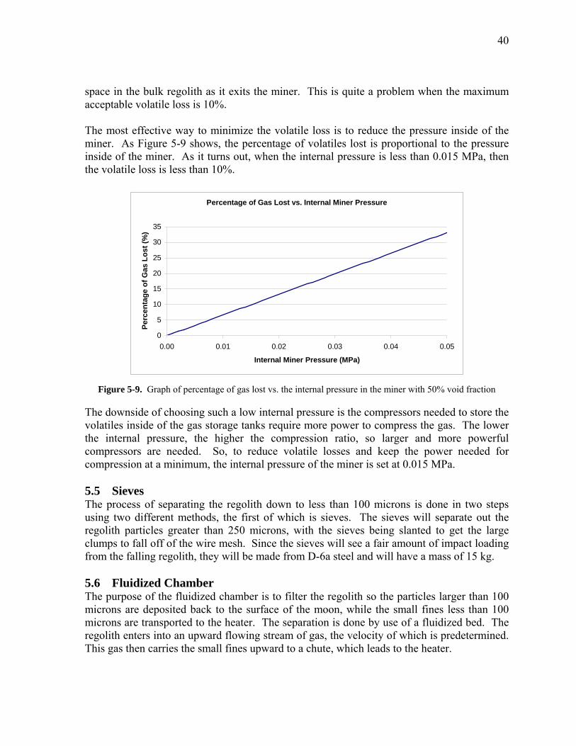
40
space in the bulk regolith as it exits the miner. This is quite a problem when the maximum acceptable volatile loss is 10%. The most effective way to minimize the volatile loss is to reduce the pressure inside of the miner. As Figure 5-9 shows, the percentage of volatiles lost is proportional to the pressure inside of the miner. As it turns out, when the internal pressure is less than 0.015 MPa, then the volatile loss is less than 10%.
Percentage of Gas Lost vs. Internal Miner Pressure
0
5
10
15
20
25
30
35
0.00 0.01 0.02 0.03 0.04 0.05
Internal Miner Pressure (MPa)
Perc
enta
ge o
f Gas
Los
t (%
)
Figure 5-9. Graph of percentage of gas lost vs. the internal pressure in the miner with 50% void fraction
The downside of choosing such a low internal pressure is the compressors needed to store the volatiles inside of the gas storage tanks require more power to compress the gas. The lower the internal pressure, the higher the compression ratio, so larger and more powerful compressors are needed. So, to reduce volatile losses and keep the power needed for compression at a minimum, the internal pressure of the miner is set at 0.015 MPa. 5.5 Sieves The process of separating the regolith down to less than 100 microns is done in two steps using two different methods, the first of which is sieves. The sieves will separate out the regolith particles greater than 250 microns, with the sieves being slanted to get the large clumps to fall off of the wire mesh. Since the sieves will see a fair amount of impact loading from the falling regolith, they will be made from D-6a steel and will have a mass of 15 kg. 5.6 Fluidized Chamber The purpose of the fluidized chamber is to filter the regolith so the particles larger than 100 microns are deposited back to the surface of the moon, while the small fines less than 100 microns are transported to the heater. The separation is done by use of a fluidized bed. The regolith enters into an upward flowing stream of gas, the velocity of which is predetermined. This gas then carries the small fines upward to a chute, which leads to the heater.
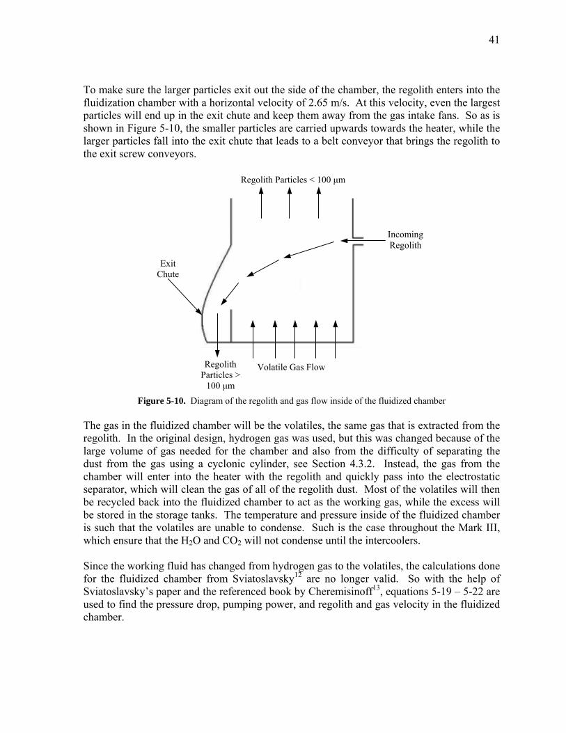
41
To make sure the larger particles exit out the side of the chamber, the regolith enters into the fluidization chamber with a horizontal velocity of 2.65 m/s. At this velocity, even the largest particles will end up in the exit chute and keep them away from the gas intake fans. So as is shown in Figure 5-10, the smaller particles are carried upwards towards the heater, while the larger particles fall into the exit chute that leads to a belt conveyor that brings the regolith to the exit screw conveyors. Regolith Particles < 100 µm
Exit Chute
Regolith Particles >
100 µm
Volatile Gas Flow
Incoming
Regolith
Figure 5-10. Diagram of the regolith and gas flow inside of the fluidized chamber The gas in the fluidized chamber will be the volatiles, the same gas that is extracted from the regolith. In the original design, hydrogen gas was used, but this was changed because of the large volume of gas needed for the chamber and also from the difficulty of separating the dust from the gas using a cyclonic cylinder, see Section 4.3.2. Instead, the gas from the chamber will enter into the heater with the regolith and quickly pass into the electrostatic separator, which will clean the gas of all of the regolith dust. Most of the volatiles will then be recycled back into the fluidized chamber to act as the working gas, while the excess will be stored in the storage tanks. The temperature and pressure inside of the fluidized chamber is such that the volatiles are unable to condense. Such is the case throughout the Mark III, which ensure that the H2O and CO2 will not condense until the intercoolers. Since the working fluid has changed from hydrogen gas to the volatiles, the calculations done for the fluidized chamber from Sviatoslavsky12 are no longer valid. So with the help of Sviatoslavsky�s paper and the referenced book by Cheremisinoff13, equations 5-19 � 5-22 are used to find the pressure drop, pumping power, and regolith and gas velocity in the fluidized chamber.
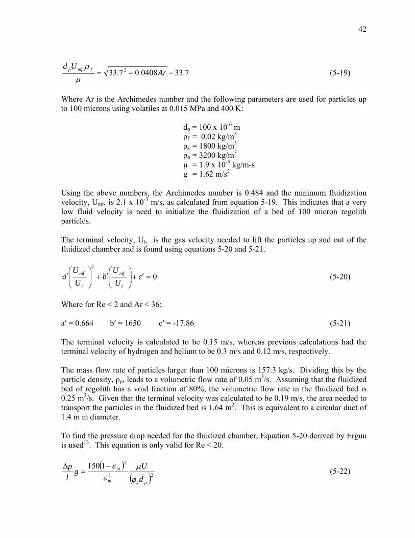
42
7.330408.07.33 2 −+= ArUd fmfp
µρ
(5-19)
Where Ar is the Archimedes number and the following parameters are used for particles up to 100 microns using volatiles at 0.015 MPa and 400 K:
dp = 100 x 10-6 m ρf = 0.02 kg/m3
ρs = 1800 kg/m3 ρp = 3200 kg/m3 µ = 1.9 x 10⁻⁵ kg/m-s g = 1.62 m/s2
Using the above numbers, the Archimedes number is 0.484 and the minimum fluidization velocity, Umf, is 2.1 x 10⁻³ m/s, as calculated from equation 5-19. This indicates that a very low fluid velocity is need to initialize the fluidization of a bed of 100 micron regolith particles. The terminal velocity, Ut, is the gas velocity needed to lift the particles up and out of the fluidized chamber and is found using equations 5-20 and 5-21.
02
=′+
′+
′ c
UU
bU
Ua
t
mf
t
mf (5-20)
Where for Re < 2 and Ar < 36: a′ = 0.664 b′ = 1650 c′ = -17.86 (5-21) The terminal velocity is calculated to be 0.15 m/s, whereas previous calculations had the terminal velocity of hydrogen and helium to be 0.3 m/s and 0.12 m/s, respectively. The mass flow rate of particles larger than 100 microns is 157.3 kg/s. Dividing this by the particle density, ρp, leads to a volumetric flow rate of 0.05 m3/s. Assuming that the fluidized bed of regolith has a void fraction of 80%, the volumetric flow rate in the fluidized bed is 0.25 m3/s. Given that the terminal velocity was calculated to be 0.19 m/s, the area needed to transport the particles in the fluidized bed is 1.64 m2. This is equivalent to a circular duct of 1.4 m in diameter. To find the pressure drop needed for the fluidized chamber, Equation 5-20 derived by Ergun is used13. This equation is only valid for Re < 20.
( )( )23
21150
psm
m
dUg
lp
φ
µεε−
=∆ (5-22)
43
The mean void fraction, εm, is 0.8, the duct length, l, is 2 m and the mean particle diameter,
pd , is 35 microns. The superficial fluid velocity, U = Utεm, is then calculated to be 0.12 m/s. The sphericity shape factor, φs, is assumed to be 0.5. It is defined as to be the ratio of the surface area of the sphere having the same volume as the particle to the actual surface area of the particle, and. With these values, the pressure drop was calculated to be 27 kPa. Using the superficial fluid velocity, the volumetric, V , for the circular duct is equal to 0.2. Using this and the above value for the pressure drop, the pumping power can be calculated from equation 5-23.
&
pVP ∆= & [kW] (5-23)
For the above values, the pumping power is 5.39 kW, slightly less than the 6.3 kW for the Mark II miner configuration. Since the regolith is very abrasive and will wear the walls of the fluidized chamber, a thin layer of 6150 steel will be added to the interior walls of the fluidized chamber for abrasion resistance. The total mass of the fluidized chamber, including the pump, is about 50 kg. For startup operations, a mixture of volatiles will need to be stored in the gas storage tanks to be used to for the fluidized chamber, since the operation of the fluidized chamber depends on the gas used as the working fluid. This gas will then be recycled until enough gas is extracted from the regolith to slowly replace the gas mixture as the extracted and startup gasses mix together. 5.7 Heater The heater is another design component taken directly from the design of the Mark II, see Chapter 2. The heater is made up of three different sections; a preheater, a main heater, and a recouperator. The energy for the heater is in the form of beamed solar power from the solar collector and is used to boil the sodium that surrounds the main heater heat pipes. The main heater heat pipes then heat up the regolith. The preheater and recouperator are made from 316 stainless steel, using working fluids of water and mercury; the main heater is made from molybdenum alloy, using a potassium working fluid. The main heater consists of approximately 4000 heat pipes, with the preheater and recouperator consisting of 21,500 heat pipes. The heater will also have an enclosure made from 316 stainless steel to help confine the heat. The overall mass of the heater is 1 tonne, with a width of 5.4 meters, depth of 2 meters, and height of 3 meters. The preheater and recouperator work together in a heat exchanger fashion to transfer energy from the hot waste regolith leaving the heater to the cool regolith entering the heater. A maximum temperature of 700ûC is attained inside the main heater, but the regolith leaving the heater is only at 400 ºC. This recycling of heat allows the heater to be 85% efficient, which is very important since it takes 12.3 MW to heat the regolith14.
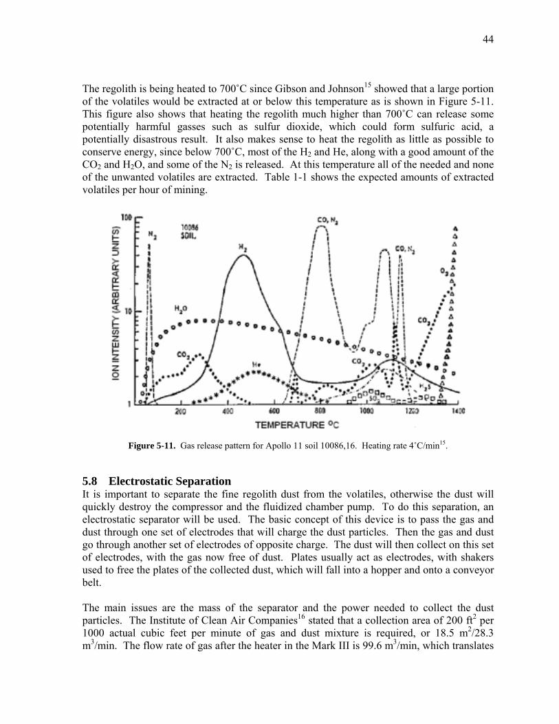
44
The regolith is being heated to 700ûC since Gibson and Johnson15 showed that a large portion of the volatiles would be extracted at or below this temperature as is shown in Figure 5-11. This figure also shows that heating the regolith much higher than 700ûC can release some potentially harmful gasses such as sulfur dioxide, which could form sulfuric acid, a potentially disastrous result. It also makes sense to heat the regolith as little as possible to conserve energy, since below 700ûC, most of the H2 and He, along with a good amount of the CO2 and H2O, and some of the N2 is released. At this temperature all of the needed and none of the unwanted volatiles are extracted. Table 1-1 shows the expected amounts of extracted volatiles per hour of mining.
Figure 5-11. Gas release pattern for Apollo 11 soil 10086,16. Heating rate 4ûC/min15.
5.8 Electrostatic Separation It is important to separate the fine regolith dust from the volatiles, otherwise the dust will quickly destroy the compressor and the fluidized chamber pump. To do this separation, an electrostatic separator will be used. The basic concept of this device is to pass the gas and dust through one set of electrodes that will charge the dust particles. Then the gas and dust go through another set of electrodes of opposite charge. The dust will then collect on this set of electrodes, with the gas now free of dust. Plates usually act as electrodes, with shakers used to free the plates of the collected dust, which will fall into a hopper and onto a conveyor belt. The main issues are the mass of the separator and the power needed to collect the dust particles. The Institute of Clean Air Companies16 stated that a collection area of 200 ft2 per 1000 actual cubic feet per minute of gas and dust mixture is required, or 18.5 m2/28.3 m3/min. The flow rate of gas after the heater in the Mark III is 99.6 m3/min, which translates
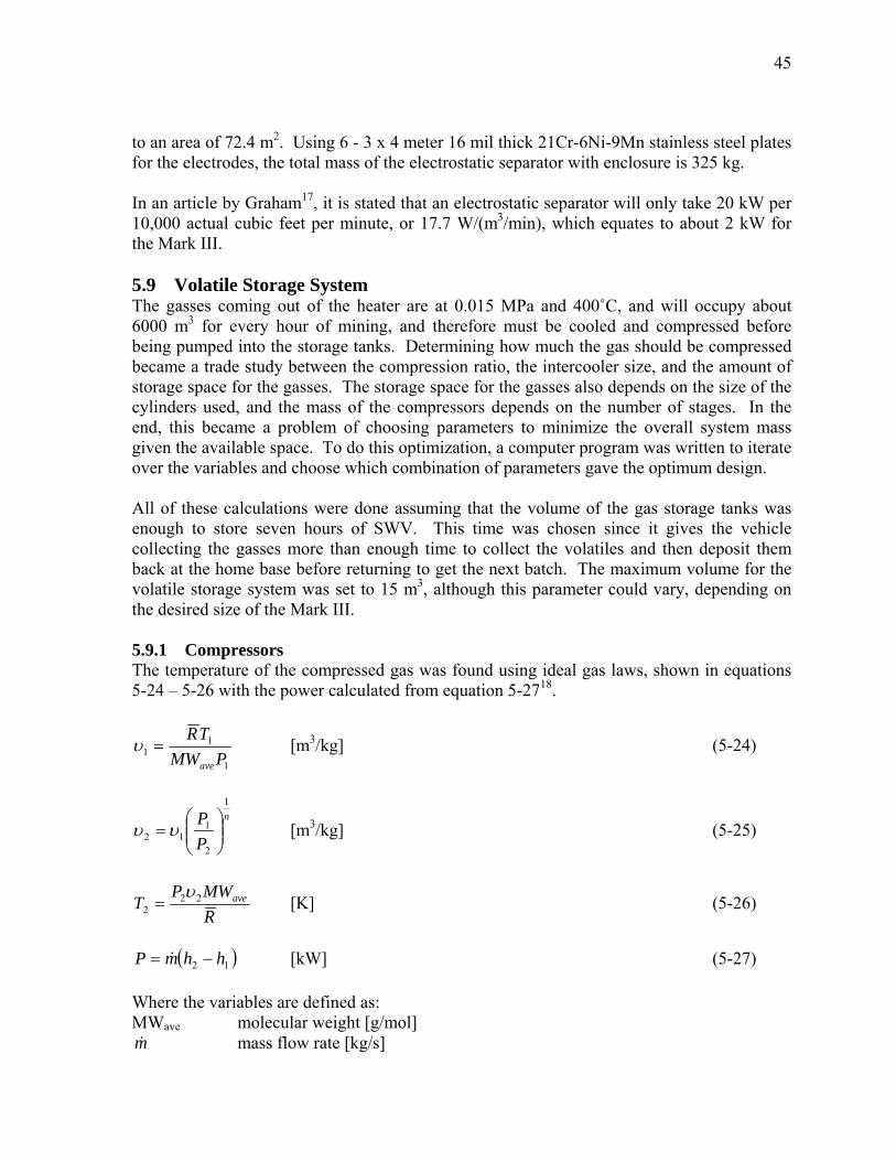
45
to an area of 72.4 m2. Using 6 - 3 x 4 meter 16 mil thick 21Cr-6Ni-9Mn stainless steel plates for the electrodes, the total mass of the electrostatic separator with enclosure is 325 kg. In an article by Graham17, it is stated that an electrostatic separator will only take 20 kW per 10,000 actual cubic feet per minute, or 17.7 W/(m3/min), which equates to about 2 kW for the Mark III. 5.9 Volatile Storage System The gasses coming out of the heater are at 0.015 MPa and 400ûC, and will occupy about 6000 m3 for every hour of mining, and therefore must be cooled and compressed before being pumped into the storage tanks. Determining how much the gas should be compressed became a trade study between the compression ratio, the intercooler size, and the amount of storage space for the gasses. The storage space for the gasses also depends on the size of the cylinders used, and the mass of the compressors depends on the number of stages. In the end, this became a problem of choosing parameters to minimize the overall system mass given the available space. To do this optimization, a computer program was written to iterate over the variables and choose which combination of parameters gave the optimum design. All of these calculations were done assuming that the volume of the gas storage tanks was enough to store seven hours of SWV. This time was chosen since it gives the vehicle collecting the gasses more than enough time to collect the volatiles and then deposit them back at the home base before returning to get the next batch. The maximum volume for the volatile storage system was set to 15 m3, although this parameter could vary, depending on the desired size of the Mark III. 5.9.1 Compressors The temperature of the compressed gas was found using ideal gas laws, shown in equations 5-24 � 5-26 with the power calculated from equation 5-2718.
1
11 PMW
TR
ave
=υ [m3/kg] (5-24)
n
PP
1
2
112
=υυ [m3/kg] (5-25)
RMWP
T ave222
υ= [K] (5-26)
( 12 hhmP −= & ) [kW] (5-27)
Where the variables are defined as: MWave molecular weight [g/mol] m& mass flow rate [kg/s]
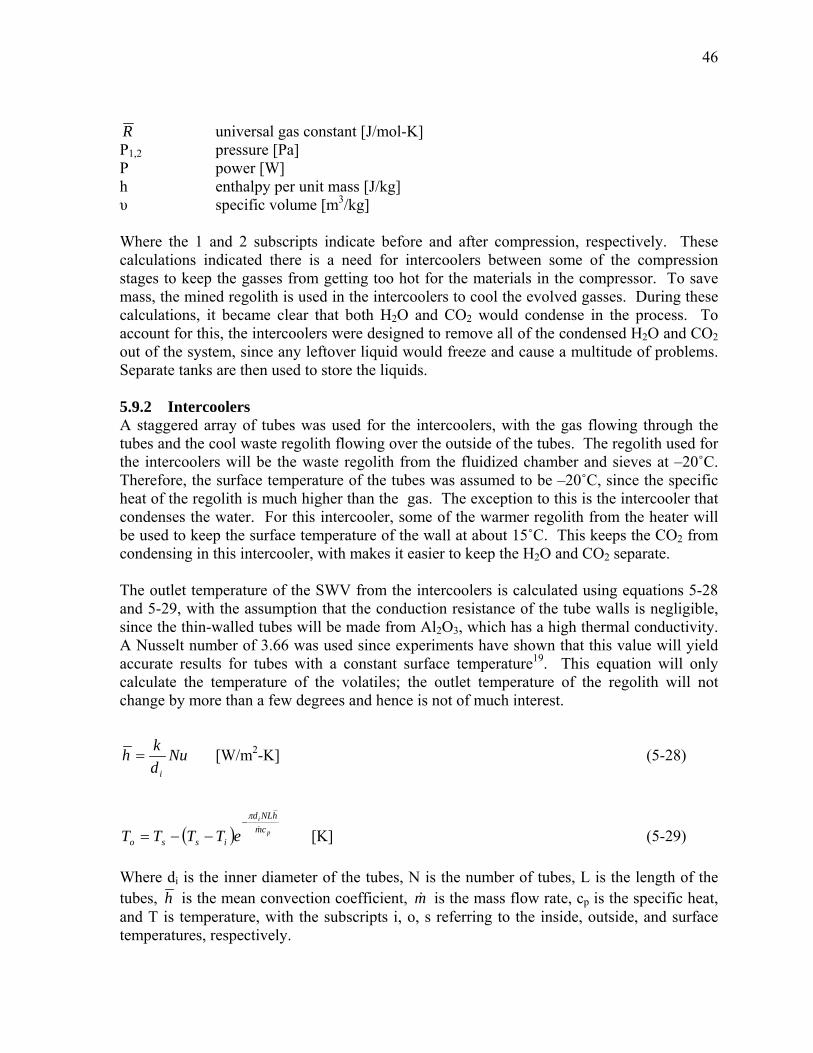
46
R universal gas constant [J/mol-K] P1,2 pressure [Pa] P power [W] h enthalpy per unit mass [J/kg] υ specific volume [m3/kg] Where the 1 and 2 subscripts indicate before and after compression, respectively. These calculations indicated there is a need for intercoolers between some of the compression stages to keep the gasses from getting too hot for the materials in the compressor. To save mass, the mined regolith is used in the intercoolers to cool the evolved gasses. During these calculations, it became clear that both H2O and CO2 would condense in the process. To account for this, the intercoolers were designed to remove all of the condensed H2O and CO2 out of the system, since any leftover liquid would freeze and cause a multitude of problems. Separate tanks are then used to store the liquids. 5.9.2 Intercoolers A staggered array of tubes was used for the intercoolers, with the gas flowing through the tubes and the cool waste regolith flowing over the outside of the tubes. The regolith used for the intercoolers will be the waste regolith from the fluidized chamber and sieves at �20ûC. Therefore, the surface temperature of the tubes was assumed to be �20ûC, since the specific heat of the regolith is much higher than the gas. The exception to this is the intercooler that condenses the water. For this intercooler, some of the warmer regolith from the heater will be used to keep the surface temperature of the wall at about 15ûC. This keeps the CO2 from condensing in this intercooler, with makes it easier to keep the H2O and CO2 separate. The outlet temperature of the SWV from the intercoolers is calculated using equations 5-28 and 5-29, with the assumption that the conduction resistance of the tube walls is negligible, since the thin-walled tubes will be made from Al2O3, which has a high thermal conductivity. A Nusselt number of 3.66 was used since experiments have shown that this value will yield accurate results for tubes with a constant surface temperature19. This equation will only calculate the temperature of the volatiles; the outlet temperature of the regolith will not change by more than a few degrees and hence is not of much interest.
Nudkh
i
= [W/m2-K] (5-28)
( ) p
i
cmhNLd
isso eTTTT &
π−
−−= [K] (5-29)
Where di is the inner diameter of the tubes, N is the number of tubes, L is the length of the tubes, h is the mean convection coefficient, is the mass flow rate, cm& p is the specific heat, and T is temperature, with the subscripts i, o, s referring to the inside, outside, and surface temperatures, respectively.
47
5.9.3 Gas Storage Tanks Carbon-carbon composites are used for the gas storage tanks since these materials are widely used for lightweight pressure vessel applications (i.e. airplanes) due to their extremely high strength to weight ratio. The downside of using carbon-carbon is that the fibers are only strong in the axial direction, so they do not work well for applications requiring strength in multiple directions. This is why it was decided to go with cylindrical gas storage tanks with spherical end caps since the loading is biaxial for cylindrical tanks. Using a spherical tank would have lower stresses, but the in-plane loading would be the same in all directions, making it more difficult to use carbon-carbon composites. These tanks will be covered in layers of insulation to ensure that the incoming heat flux from the heater and sunlight will be kept to a minimum. This will allow for the storage tanks to stay near the 250ûC that the compressed volatiles are entering the tanks at and therefore keep the volume of the gas at a minimum. 5.9.4 Results The results of these calculations gave an optimum pressure of 20 MPa, with 6 stages of compression and intercoolers after the second, third, and sixth compressors. Intercoolers are not needed after the first, fourth, and fifth compressors since the temperatures after these compressors are not sufficiently high to warrant the need for cooling. The compression ratio for each compressor is set equal, about 3.3, to reduce the power required and exit temperature of the gas when leaving the compressor.
48
Figure 5-12 shows the condensing and intercooling process, including pressures and temperatures. H2O is condensed in the second intercooler at which time the pressure is 0.17 MPa, with the temperature at the end of the intercooler being around 25ûC. The condensed water is then collected and pumped into a storage tank. The CO2 is condensed in the last intercooler, where the pressure is 20 MPa, with the temperature in the intercooler at about �20ûC. Both intercoolers are exceptionally long to make sure that all of the H2O and CO2 is condensed, since any remaining vapor would later freeze and possibly clog the system. The mass of the compressors was found by looking at three compressor manufacturers and finding compressors that closely matched the compressors needed for the miner20,21,22. Some interpolation was done to get as close as possible to the needed compression ratio and maximum pressure. The overall mass of the compressors is 310 kg. It was determined that 19 tanks, 4 meters in length, and 0.2 meters in radius would yield the optimum results. Pressure relief valves will be an inherent safety feature in case the pressure exceeds the design limit of 20 MPa. These valves will release the volatiles into space rather than overloading the tank and increasing the chance of a rapid decompression, which could severely damage the miner. The importance of the optimization of the storage system can be seen in the mass of the gas storage tanks, which is 1320 kg, over 10% of the overall mass.
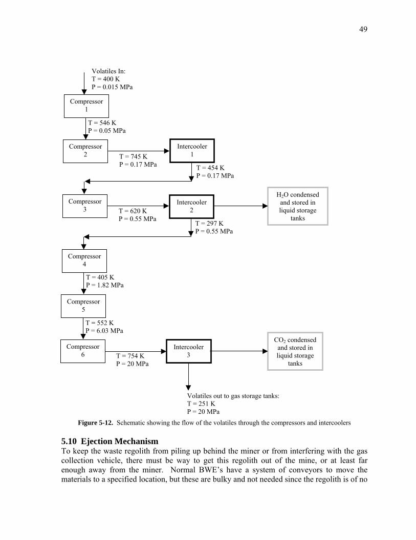
49
T = 754 K P = 20 MPa
T = 620 K P = 0.55 MPa
Compressor 6
T = 552 K P = 6.03 MPa
T = 405 K P = 1.82 MPa
T = 745 K P = 0.17 MPa
CO2 condensed and stored in liquid storage
tanks
H2O condensed and stored in liquid storage
tanks
T = 454 K P = 0.17 MPa
T = 297 K P = 0.55 MPa
T = 546 K P = 0.05 MPa
Volatiles In: T = 400 K P = 0.015 MPa
Intercooler 1
Intercooler 2
Intercooler 3
Compressor 5
Compressor 4
Compressor 3
Compressor 2
Compressor 1
Volatiles out to gas storage tanks: T = 251 K P = 20 MPa
Figure 5-12. Schematic showing the flow of the volatiles through the compressors and intercoolers 5.10 Ejection Mechanism To keep the waste regolith from piling up behind the miner or from interfering with the gas collection vehicle, there must be way to get this regolith out of the mine, or at least far enough away from the miner. Normal BWE�s have a system of conveyors to move the materials to a specified location, but these are bulky and not needed since the regolith is of no
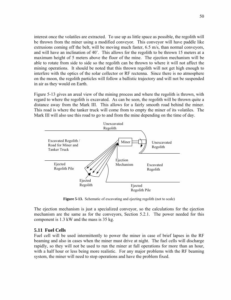
50
interest once the volatiles are extracted. To use up as little space as possible, the regolith will be thrown from the miner using a modified conveyor. This conveyor will have paddle like extrusions coming off the belt, will be moving much faster, 6.5 m/s, than normal conveyors, and will have an inclination of 40û. This allows for the regolith to be thrown 15 meters at a maximum height of 5 meters above the floor of the mine. The ejection mechanism will be able to rotate from side to side so the regolith can be thrown to where it will not affect the mining operations. It should be noted that this thrown regolith will not get high enough to interfere with the optics of the solar collector or RF rectenna. Since there is no atmosphere on the moon, the regolith particles will follow a ballistic trajectory and will not be suspended in air as they would on Earth. Figure 5-13 gives an areal view of the mining process and where the regolith is thrown, with regard to where the regolith is excavated. As can be seen, the regolith will be thrown quite a distance away from the Mark III. This allows for a fairly smooth road behind the miner. This road is where the tanker truck will come from to empty the miner of its volatiles. The Mark III will also use this road to go to and from the mine depending on the time of day.
Ejected Regolith
Miner
Ejected Regolith Pile
Excavated Regolith
Ejected Regolith Pile
Unexcavated Regolith
Excavated Regolith / Road for Miner and Tanker Truck
Ejection Mechanism
Unexcavated Regolith
Figure 5-13. Schematic of excavating and ejecting regolith (not to scale) The ejection mechanism is just a specialized conveyor, so the calculations for the ejection mechanism are the same as for the conveyors, Section 5.2.1. The power needed for this component is 1.3 kW and the mass is 35 kg. 5.11 Fuel Cells Fuel cell will be used intermittently to power the miner in case of brief lapses in the RF beaming and also in cases when the miner must drive at night. The fuel cells will discharge rapidly, so they will not be used to run the miner at full operations for more than an hour, with a half hour or less being more realistic. For any major problems with the RF beaming system, the miner will need to stop operations and have the problem fixed.
51
There is a considerable amount of research going on in this field today, so it is difficult to know what the capabilities of fuel cells will be in the future. To get an idea of the approximate mass needed, numbers were taken out of tables from the NASA Capabilities Roadmaps Report23. In this report, it is estimated that fuel cells will have a specific power of 400 W/kg in 7 years with energy densities of 400 � 600 Wh/kg possible in 7 � 20 years. Since the power required is about 350 kW, this leads to a fuel cell mass of 700 kg. However, if any major advances are discovered, this number could drop dramatically. It seems as though with an energy density of 400 � 600 Wh/kg and a mass of 700 kg that it would be possible to run at full power using fuel cells for an hour, however this is not the case since fuel cells will discharge much more rapidly when at full capacity. This is why the fuel cells will only be used for long periods of time when driving at night, since the locomotion requires less than 20 kW. The Mark III will be able to drive for at least 14 hours using fully charged fuel cells, which is much longer than should ever be needed, given that the base camp will never be farther than 10 km away and the Mark III will be able to travel at least 2 km/hr. The fuel cells will be recharged by the RF beaming system whenever the miner is not operating at full capacity. Fuel cells were chosen over batteries due to the higher energy densities possible in fuel cells over the next 10 years. But if batteries make a sudden surge in energy density, then there is no reason not to use batteries instead of fuel cells. 5.12 Solar Collector As previously mentioned, the energy for the heater comes from concentrated sunlight beamed from a large stationary dish to the solar collector mounted on top of the miner. The solar collector then further concentrates the sunlight and directs it into the heater to provide the 12.3 MW needed to heat the working fluid, which in turn heats the regolith10. The small refocusing mirror will be made from very highly reflective mirrors, with reflectivities up to 99.9%24. These mirrors will also be used to redirect the concentrated sunlight into the heater. The mirrors will have a fused silica substrate and a dielectric coating with the optimum wavelength centered on the visible spectrum. The substrate can withstand a maximum continuous temperature of 900ºC25. Such a high reflectivity and operating temperature is needed for the mirrors since the concentration of sunlight is on the order of 45,700:1. This was calculated using equation 5-30, where Sc is the solar constant, 1370 W/m2, Preq is the power required for the heater, 12.3 MW, Ap is the projected area of the mirror 0.2 m2, and Fm is a factor to correct for the imperfect reflectivities of the mirrors, 1.002.
mcp
reqm F
SAP
C = (5-30)
52
To calculate the temperature of the mirrors, the radiation heat transfer equation, equations 5-31 and 5-32, are used, where σ is the Stefan-Boltzmann constant, 5.67 x 10⁻⁸ W/m2-K, Rm is the reflectivity of the mirror, Tm is the temperature in K, and q" is the heat flux. With these parameters, the operating temperature of the mirror, will be about 700 ºC.
( ) ms
pmc C
AA
RSq −=′′ 1 (5-31)
4
mTq σ=′′ (5-32) The parabolic surface area of the mirror, As, is found using equation 5-33, where dm is the diameter of the focusing mirror, 0.5 m, and hm is the depth of the focusing mirror, 0.15 m.
−
+
=
323
22
2 24
212m
mm
m
ms
dh
dh
dA
π [m2] (5-33)
The ratio of the projected area over the surface area of the mirror in equation 5-31 is due to the fact that the surface area is the area over which the heat will be absorbed and is therefore the area of interest when calculating the temperature of the mirror. However, the concentration of the beamed sunlight is dependent upon the projected area. The difference in concentration between the beamed light and the incident light is just the ratio of the two areas, which is why that ratio is present in equation 5-31. This process is an iterative process to find a diameter for the mirror that will correspond to an operating temperature low enough to not melt the mirror. The same calculations can be done for the mirrors that redirect the focused light from the center of the solar collector down into the heater. The only changes would be Rm, but since the reflectivities are so close to one, the difference is insignificant. To save mass, the solar collector will use highly polished aluminized mylar for the collecting dish instead of a large mirror. Aluminized mylar can reach reflectivities up to 98.9%26 with an operating temperature range from �250 ºC � 200 ºC27. The process in calculating the diameter, concentration, and material temperatures is the same as was described for equations 5-30 � 5-33, except that the size of the solar collector must be slightly increased to make up for the hole in the center of the dish where the concentrated beam enters the shaft. This makes an almost negligible affect, but must be accounted for to ensure that enough energy is delivered into the heater. The results from this calculation are a solar collector diameter of 9 m, a concentration of 140, and an operating temperature of 150ºC, with a depth of the parabolic dish at 2 m. Since the aluminized mylar can operate at temperatures up to 200ºC, it would be possible to shrink the diameter of the collector down to
53
7 m, but this would leave no room for error and would most likely severely limit the lifetime of the collector. So it was decided that the diameter should remain at 9 m. The diameter of the refocusing mirror for the solar collector will be 0.5 m. This will match the inner diameter of the solar collector shaft, which will make it easier to redirect the concentrated sunlight from the refocusing mirror down into the heater. The aluminized mylar for the solar collector will be 0.5 mm thick to ensure that the mylar will keep its parabolic shape. There will also be a structure made of Ti-6Al-4V that will support the aluminized mylar dish. The parabolic solar collector will be manufactured in multiple parts so that it can easily fit into a rocket. The solar collector will be held up by a thin circular shaft, also made of Ti-6Al-4V, that acts as a path for the light to get into the heater. The interior of this shaft will be lined with aluminized mylar to deflect any wayward sun rays into the heater. This shaft will also have an extension to hold up the RF rectenna. The shaft was calculated to withstand buckling loads and bending loads with the mass of the collector and RF antenna offset by up to 4 meters. The total mass of the solar collector, shaft, and structure is 95 kg. 5.13 RF Rectenna The RF rectenna will be mounted above the solar collector using a shaft connected to the solar collector. The rectenna is made up from an array of integrated circuits that will convert the RF beam into DC power. This array will be mounted on top of a gimbal that will keep the array pointed at the larger stationary RF antenna. The main parameter in RF beaming is the frequency of the RF wave. The 2.45 GHz range has been studied the most as it is the frequency of microwave ovens, but work has also been done on frequencies up to 300 GHz. The frequency is important since all of the parameters of the system depend upon it, from the efficiencies to the size of the antennas. 5.13.1 Efficiencies The size of the transmitting and receiving dishes, along with the efficiencies are dependent upon the frequency of the RF wave28. The transmission frequency is found using equation 5-34 and Figure 5-14.
t
rt
dAA
λτ = (5-34)
Where τ is a unitless parameter, λ is the wavelength of the RF wave, dt is the distance from the stationary antenna to the rectenna, at most 3 km, At is the area of the transmitting antenna, and Ar is the area of the receiving antenna. Figure 5-14 shows a plot of the transmission efficiency versus τ. As can be seen, the efficiency nears one as τ approaches 2.5. So the dish sizes were chosen to get τ equal to 2 .5.
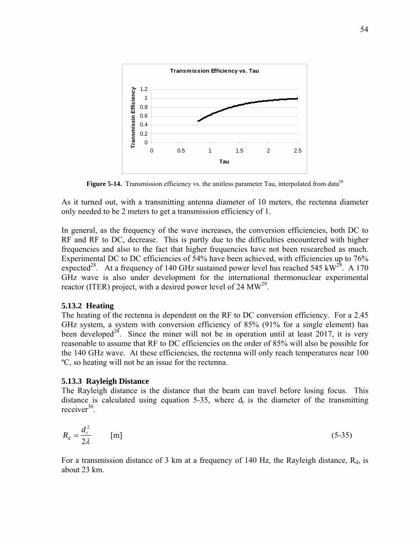
54
Transmission Efficiency vs. Tau
00.20.40.60.8
11.2
0 0.5 1 1.5 2 2.
Tau
Tran
smis
sin
Effic
ienc
y
5
Figure 5-14. Transmission efficiency vs. the unitless parameter Tau, interpolated from data28
As it turned out, with a transmitting antenna diameter of 10 meters, the rectenna diameter only needed to be 2 meters to get a transmission efficiency of 1. In general, as the frequency of the wave increases, the conversion efficiencies, both DC to RF and RF to DC, decrease. This is partly due to the difficulties encountered with higher frequencies and also to the fact that higher frequencies have not been researched as much. Experimental DC to DC efficiencies of 54% have been achieved, with efficiencies up to 76% expected28. At a frequency of 140 GHz sustained power level has reached 545 kW29. A 170 GHz wave is also under development for the international thermonuclear experimental reactor (ITER) project, with a desired power level of 24 MW29. 5.13.2 Heating The heating of the rectenna is dependent on the RF to DC conversion efficiency. For a 2.45 GHz system, a system with conversion efficiency of 85% (91% for a single element) has been developed28. Since the miner will not be in operation until at least 2017, it is very reasonable to assume that RF to DC efficiencies on the order of 85% will also be possible for the 140 GHz wave. At these efficiencies, the rectenna will only reach temperatures near 100 ºC, so heating will not be an issue for the rectenna. 5.13.3 Rayleigh Distance The Rayleigh distance is the distance that the beam can travel before losing focus. This distance is calculated using equation 5-35, where dt is the diameter of the transmitting receiver30.
λ2
2t
dd
R = [m] (5-35)
For a transmission distance of 3 km at a frequency of 140 Hz, the Rayleigh distance, Rd, is about 23 km.
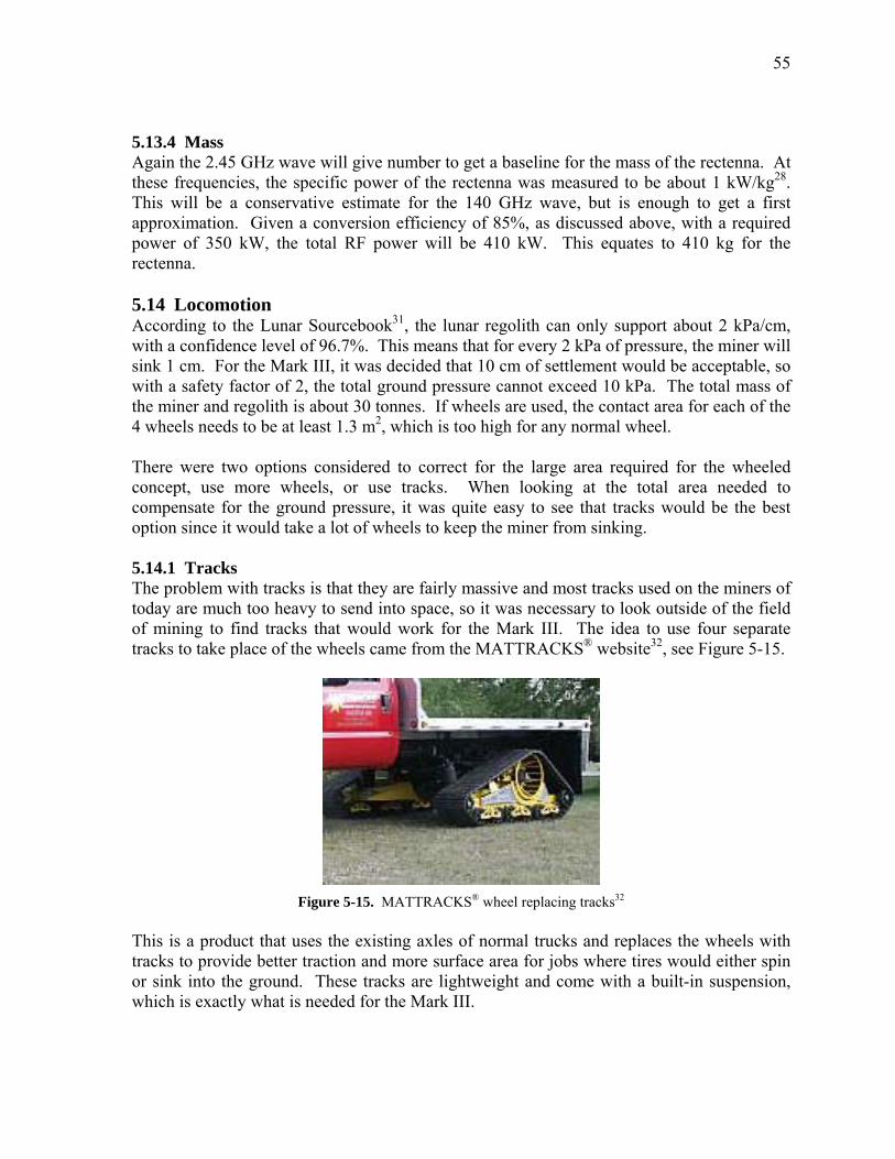
55
5.13.4 Mass Again the 2.45 GHz wave will give number to get a baseline for the mass of the rectenna. At these frequencies, the specific power of the rectenna was measured to be about 1 kW/kg28. This will be a conservative estimate for the 140 GHz wave, but is enough to get a first approximation. Given a conversion efficiency of 85%, as discussed above, with a required power of 350 kW, the total RF power will be 410 kW. This equates to 410 kg for the rectenna. 5.14 Locomotion According to the Lunar Sourcebook31, the lunar regolith can only support about 2 kPa/cm, with a confidence level of 96.7%. This means that for every 2 kPa of pressure, the miner will sink 1 cm. For the Mark III, it was decided that 10 cm of settlement would be acceptable, so with a safety factor of 2, the total ground pressure cannot exceed 10 kPa. The total mass of the miner and regolith is about 30 tonnes. If wheels are used, the contact area for each of the 4 wheels needs to be at least 1.3 m2, which is too high for any normal wheel. There were two options considered to correct for the large area required for the wheeled concept, use more wheels, or use tracks. When looking at the total area needed to compensate for the ground pressure, it was quite easy to see that tracks would be the best option since it would take a lot of wheels to keep the miner from sinking. 5.14.1 Tracks The problem with tracks is that they are fairly massive and most tracks used on the miners of today are much too heavy to send into space, so it was necessary to look outside of the field of mining to find tracks that would work for the Mark III. The idea to use four separate tracks to take place of the wheels came from the MATTRACKS® website32, see Figure 5-15.
Figure 5-15. MATTRACKS® wheel replacing tracks32
This is a product that uses the existing axles of normal trucks and replaces the wheels with tracks to provide better traction and more surface area for jobs where tires would either spin or sink into the ground. These tracks are lightweight and come with a built-in suspension, which is exactly what is needed for the Mark III.
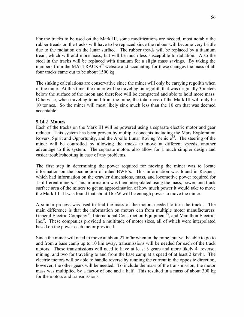
56
For the tracks to be used on the Mark III, some modifications are needed, most notably the rubber treads on the tracks will have to be replaced since the rubber will become very brittle due to the radiation on the lunar surface. The rubber treads will be replaced by a titanium tread, which will add more mass, but will be much less susceptible to radiation. Also the steel in the tracks will be replaced with titanium for a slight mass savings. By taking the numbers from the MATTRACKS® website and accounting for these changes the mass of all four tracks came out to be about 1500 kg. The sinking calculations are conservative since the miner will only be carrying regolith when in the mine. At this time, the miner will be traveling on regolith that was originally 3 meters below the surface of the moon and therefore will be compacted and able to hold more mass. Otherwise, when traveling to and from the mine, the total mass of the Mark III will only be 10 tonnes. So the miner will most likely sink much less than the 10 cm that was deemed acceptable. 5.14.2 Motors Each of the tracks on the Mark III will be powered using a separate electric motor and gear reducer. This system has been proven by multiple concepts including the Mars Exploration Rovers, Spirit and Opportunity, and the Apollo Lunar Roving Vehicle33. The steering of the miner will be controlled by allowing the tracks to move at different speeds, another advantage to this system. The separate motors also allow for a much simpler design and easier troubleshooting in case of any problems. The first step in determining the power required for moving the miner was to locate information on the locomotion of other BWE�s. This information was found in Rasper4, which had information on the crawler dimensions, mass, and locomotive power required for 15 different miners. This information was then interpolated using the mass, power, and track surface area of the miners to get an approximation of how much power it would take to move the Mark III. It was found that about 16 kW will be enough power to move the miner. A similar process was used to find the mass of the motors needed to turn the tracks. The main difference is that the information on motors can from multiple motor manufacturers: General Electric Company34, International Construction Equipment35, and Marathon Electric, Inc.9. These companies provided a multitude of motor sizes, all of which were interpolated based on the power each motor provided. Since the miner will need to move at about 27 m/hr when in the mine, but yet be able to go to and from a base camp up to 10 km away, transmissions will be needed for each of the track motors. These transmissions will need to have at least 3 gears and more likely 4: reverse, mining, and two for traveling to and from the base camp at a speed of at least 2 km/hr. The electric motors will be able to handle reverse by running the current in the opposite direction, however, the other gears will be needed. To include the mass of the transmission, the motor mass was multiplied by a factor of one and a half. This resulted in a mass of about 300 kg for the motors and transmissions.
57
5.15 Chassis The chassis of the Mark III must be very sturdy to support all of the components. It is made from Ti-6Al-4V for the materials high strength to weight ratio. The chassis consists of 4 main beams that make a 3 by 8 meter rectangle. The calculations on these beams was done assuming the worst possible loading scenario, a point load at the center of the chassis, with the load being the mass of the miner full of regolith, approximately 30 tonnes. Basic beam bending theory was used when calculating the stresses on these beams. To reduce mass, the beams were given a �C� shape cross-section with a base of 4.2 cm, height of 8.5 cm, and thickness of 5 mm. These dimensions give a safety factor of two and an overall mass of 80 kg. 5.16 Enclosure To keep the vacuum seal inside of the miner, there will be an enclosure around the main body of the miner. Figure 5-16 shows the Mark III, minus the solar collector, with the enclosure shown in white. The parts not inside of this enclosure will be the BWE, gas storage tanks, liquid storage tanks, heater, electrostatic separator, and ejection mechanism.
Figure 5-16. Mark III miner with enclosure, shown in white
The storage tanks are left out of the enclosure to allow for easy access for the tanker truck to pump the volatiles out of the miner, however, they will have their own separate enclosures with insulation to keep the tanks cool and dust free. The heater and electrostatic separator also have separate enclosures. The vacuum seal is achieved at the screw conveyors, so these components will be half in and half out of the enclosure. To reduce mass, the enclosure will be made from 0.5 mm thick C-C and has an approximate mass of 50 kg. The enclosure will not only keep the gas in, it will keep the dust away from the mechanical components and electronics. Any dust in mechanical components will slowly wear away at the moving parts due to the abrasiveness of the regolith and the static charge that can accompany the regolith could easily provide enough energy to fry electrical components. This is why the enclosure covers as much as the miner as is feasible.
58
[1] Thin Section Bearings of America (2005). Retrieved July 28, 2005, from
www.thinsectionbearing.com [2] Kaydon Incorporation, Inc (2005). Retrieved July 28, 2005, from www.reali-
slim.com [3] Tulsa Winch Group (2005). Retrieved May 5, 2005, from www.team-twg.com [4] Rasper, Ludwig. (1975). The Bucket Wheel Excavator – Development, Design,
Application. Bay Village, Ohio : Trans Tech Publications [5] ANSYS (Version 7.1) (2005) [Computer software]. Canonsburg, PA: ANSYS Inc. [6] Conveyor Equipment Manufacturers Association (1979). Belt Conveyors for Bulk
Materials, Second Edition. Boston, MA : CBI. [7] Berndorf Band (n.d.). Retrieved May 12, 2005, from www.berndorf-usa.com [8] Conveyor Equipment Manufacturers Association (1981). Screw Conveyors: CEMA
Book No. 350. Washington D.C.: CEMA [9] Marathon Electric, Inc (2004). Retrieved May 5, 2005, from
www.marathonelectric.com [10 ] Sviatoslavsky, I.N. (1993 February). The Challenge of Mining He-3 on the Lunar
Surface: How All the Parts Fit Together. Proceedings of Space 94, The 4th International Conference and Exposition of Engineering, Construction and Operations in Space, Albuquerque, NM
[11] Taylor, L. A., Schmitt, H. H., Carrier III, W. D., Nakagawa, M. (2005 February). The Lunar Dust Problem: From Liability to Asset. Proceedings of the First Space Exploration Conference: Continuing the Voyage of Discovery, Orlando, FL
[12] Sviatoslavsky, I. N. (1992 January). Lunar He-3 Mining: Improvements on the Design of the UW Mark II Lunar Miner. Proceedings of Space 92, The 3rd International Conference and Exposition of Engineering, Construction and Operations in Space, Denver, CO
[13] Cheremisinoff, N. P. and Cheremisinoff, P.N. (1984). Hydrodynamics of Gas-Solids Fluidization. Houston, TX: Gulf Publishing Co.
[14] Sviatoslavsky, I. N. (1993, July). Coaxing He3 from Lunar Regolith; Processes and Challenges. Proceedings of the Second Wisconsin Symposium on Helium-3 and Fusion Power, Madison, WI
[15] Gibson, E. K. Jr. and Johnson, S. M. (1971). �Thermal Analysis-inorganic gas release studies of lunar samples,� Proceedings of the Second Lunar Science Conference, Volume 2. The M.I.T. Press
[16] Institute of Clean Air Companies (2005). Retrieved November 11, 2005, from www.icac.com
[17] Graham, G. (n.d.). Controlling Stack Emissions in the Wood Product Industry. Retrieved November 10, 2005, from www.ppcbio.com
[18] Moran, M. J., Shapiro, H. N. (2000). Fundamentals of Engineering Thermodynamics, 4th Edition. New York, NY : John Wiley & Sons, Inc.
[19] Incorpera, F. P., DeWitt, D. P. (1996). Introduction to Heat Transfer, Third Edition. New York, NY : John Wiley & Sons, Inc.
[20] Curtis Toledo Inc. (2005). Retrieved June 30, 2005, from www.curtistoledo.com [21] KNF Neuberger, Inc (2005). Retrieved June 30, 2005, from www.knf.com
5.17 References
59
[22] Stjarnekull, C. (2005). Atlas Copco, Retrieved June 30, 2005, from www.atlascopco-
group.com [23] NASA Capability Roadmap Report (2005). Washington D.C. : Government Printing
Office [24] Los Gatos Research (n.d.). Retrieved January 30, 2006, from www.lgrinc.com [25] Melles Griot (2002), Retrieved January 31, 2006, from www.mellesgriot.com [26] Scott, R. B. (1959). Cryogenic Engineering. Toronto Canada : D. Van Nostrand
Company, Inc [27] DuPont Teijin Films (2005). Retrieved January 26, 2006 from
www.dupontteijinfilms.com [28] Brown, W. C. (1992). Beamed Microwave Power Transmission and its Application
to Space. IEEE Transactions on Microwave Theory and Techniques, 40(6), 1239-1250
[29] Dammertz, G., Alberti, S, Arnold, A., Bariou, D., Borie, E., Brand, P., et al. (2005). Development of Multimegawatt Gyrotrons for Fusion Plasma Heating and Current Drive. IEEE Transaction on Electron Devices, 52(5), 808-817
[30] Alden, A, Bouliane, P., Zhang, M. (2005 October). Some Recent Developments in Wireless Power Transmission to Micro Air Vehicles. Proceedings of the Third International Symposium on Beamed Energy Propulsion, Troy, NY
[31] Heiken, Grant H., Vaniman, David T., French, Bevan M. (1991). Lunar Sourcebook, a user’s guide to the moon. Cambridge : Cambridge University
[32] Mattracks, Inc (2001), Retrieved June 30, 2005, from www.mattracks.com [33] Zakrajsek, J. J., McKissock, D. B., Woytach, J. M., Zakrajsek, J. F., Oswald, F. B.,
McEntire, et al. (2005). Exploration Rover Concepts and Development Challenges (NASA/TM-2005-213555). Washington D.C. : Government Printing Office
[34] General Electric Company (2005). Retrieved May 5, 2005 from catalog.geindustrial.com
[35] International Construction Equipment (n.d.). Retrieved May 5, 2005, from www.iceusa.com
60
Chapter 6 Support Equipment This is the equipment that will be needed to support the mining operations. The masses and sizes are very rough approximations to give an idea of what will be needed. None of these masses are included in the mass of the Mark III. 6.1 Large Stationary Dish The optics of the large stationary dish, shown in Figure 4-7 ,are the same as those on the solar collector mounted on the Mark III. The only difference is the size, and the materials. Since the stationary dish is dealing with much less concentrated sunlight, there is no need for highly reflective mirrors, instead, all of the reflective surfaces of this dish will be made from 0.5 mm thick aluminized mylar to reduce the mass. The size of the stationary dish depends on the concentration of sunlight needed for the solar collector, and the diameter of the solar collector dish. It is easy to see that the area of the stationary dish is just the area of the solar collector dish multiplied by the needed concentration. Knowing that the concentration upon the solar collector must be 140:1, the diameter of the large stationary dish was calculated to be 110 m. Since the large stationary collector is only seeing a 1:1 concentration of sunlight, most of which is reflected, the temperature is very near the temperature of space and therefore is of no interest. The focusing mirror on the large stationary dish will depend on the overall optics of the system, since the focus must be adjustable to account for the miner being differing distances from the dish, as discussed in Section 4.2, which is not part of this research. But it is easy to see that aluminized mylar should be able to be used since the concentration on this mirror, 1.37 kW/m2 should be fairly small. The total mass of the stationary dish, including structure, is about 9.2 tonnes. It is obvious that a 110 m stationary dish is very massive and quite possibly too big of a dish to be manufactured or assembled. So if it is not possible to have that large of a dish, an array of smaller dishes could be used to get the 12.3 MW needed for the heater. This will not be a problem just so long as the Mark III does not get too close to the large stationary dish, which is why this dish will be placed at a location that is not any closer than 1 km to a mining site. However, since the Mark III will only mine 1 km2/yr, the large dish may not be such a problem. If the stationary dish is set in the middle of many mining fields, it is possible that there will be 25 km2 of mineable regolith around one stationary dish. Although it is unlikely that all of the area around one dish will be mineable, it is very possible that at least 15 km2 will be mineable. This correlates to 15 years of mining operations. Setting up such a large structure seems much more reasonable if it will be used for 15 years. The same holds true for the RF antenna and PV cells spoken of in the next two sections. 6.2 RF Antenna The RF antenna is made from an array of integrated circuits that convert DC power to a RF wave. As calculated in Section 5.13.1, the rectenna will need to be 10 meters in diameter. The antenna will receive DC power from an array of PV cells and then convert that power to a 140 GHz RF wave that will be transmitted to the Mark III. The overall DC to DC
61
efficiency of this frequency of beam has been shown to be about 53%1. The total electrical power needed for the miner is 350 kW, so the power needed from the PV cells is 650 kW. The specific power for the rectenna is not available at this time, so the 1 kW/kg specific power of the antenna will be used for an approximation. So the mass of the rectenna will be approximately 650 kg. 6.3 Photovoltaic Cell Array An array of PV cells must be used to produce the power needed to beam RF waves to the miner to be converted into the energy needed to power the miner. This collector will be flat and covered with PV cells, with a circular or rectangular geometry. This collector will also be on gimbals allowing it to track the movement of the sun. As stated in Section 6.2, the PV cells must be able to produce about 650 kW. The PV array will use a design from Entech2, which uses a parabolic lens to concentrate the sunlight to the cells that will then produce the energy. This process increases the efficiencies of the PV array and increase the specific power of the system. The areal power density is 600 W/m2 with a specific power of about 330W/kg. Using these numbers, the mass of the PV array will be 2 tonnes, with an area of about 1100 m2. Due to the large amount of PV cells required, this will most likely be split between a number of arrays. 6.4 Tanker Truck The tanker truck that will be used to empty out the volatiles from the Mark III will be a small machine consisting mainly of storage tanks. The size of these tanks will be the main determining factor of the mass of the tanker truck. With tanks capable of holding five hours of volatiles having a mass of about 1 tonne, and tanks capable of holding twenty hours of volatiles will have a mass of about 4 tonnes. The remaining components of the tanker truck will have a mass of only about 500 kg. So the total truck mass will be from 1.5 to 4.5 tonnes. 6.5 Cryogenic Separation and Storage Facility The volatiles in the tanker truck will be pumped into a cryogenic separation facility. This facility will use very large radiators to cool the liquid to cryogenic temperatures and separate the liquids as they condense. The first step will be to use a palladium membrane to separate out the H2. The volatiles will be pumped into one side of a tank with a Pd membrane, with the H2 being pumped out of the other side of the tank to ensure that all of the H2 is separated out of the gas mixture. This will be done carefully to ensure that the Pd membrane is not ruptured in the process. There are also new membranes that could be used for this separation. One of these membranes3 lets the larger molecules through, leaving the hydrogen behind, thus allowing for high pressures of hydrogen without the need for a lot of pumping. These and other technologies will need to be studied prior to designing this facility. The remaining volatiles will then be pumped into the cryogenic separator. The radiator area required to cryogenically separate the other gasses is shown in Figure 6-1. It can be seen that carbon dioxide will be the first gas liquefied, while nitrogen will be the last gas that can be liquefied by this process. The leftover gas will be a mixture of He-3 and He-4 that can be separated using cryogenically controlled leak technology4.
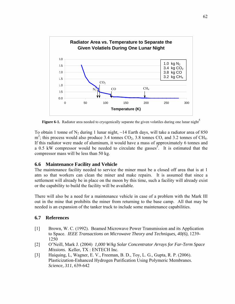
62
Radiator Area vs. Temperature to Separate the Given Volatiels During One Lunar Night
0.0
5
0
1.5
0
5
3.0
0 50 100 150 200 250 300
Temperature (K)
Rad
iato
r Are
a (m
)
0.
1.
2.
2.
Rad
iato
rAre
a(m
2 ) 1.0 kg N2 3.4 kg CO2 3.8 kg CO 3.2 kg CH4
CO2
N2 CH4 CO
Figure 6-1. Radiator area needed to cryogenically separate the given volatiles during one lunar night5 To obtain 1 tonne of N2 during 1 lunar night, ~14 Earth days, will take a radiator area of 850 m2; this process would also produce 3.4 tonnes CO2, 3.8 tonnes CO, and 3.2 tonnes of CH4. If this radiator were made of aluminum, it would have a mass of approximately 6 tonnes and a 0.5 kW compressor would be needed to circulate the gasses5. It is estimated that the compressor mass will be less than 50 kg. 6.6 Maintenance Facility and Vehicle The maintenance facility needed to service the miner must be a closed off area that is at 1 atm so that workers can clean the miner and make repairs. It is assumed that since a settlement will already be in place on the moon by this time, such a facility will already exist or the capability to build the facility will be available. There will also be a need for a maintenance vehicle in case of a problem with the Mark III out in the mine that prohibits the miner from returning to the base camp. All that may be needed is an expansion of the tanker truck to include some maintenance capabilities. 6.7 References [1] Brown, W. C. (1992). Beamed Microwave Power Transmission and its Application
to Space. IEEE Transactions on Microwave Theory and Techniques, 40(6), 1239-1250
[2] O�Neill, Mark J. (2004) 1,000 W/kg Solar Concentrator Arrays for Far-Term Space Missions. Keller, TX : ENTECH Inc.
[3] Haiquing, L, Wagner, E. V., Freeman, B. D., Toy, L. G., Gupta, R. P. (2006). Plasticization-Enhanced Hydrogen Purification Using Polymeric Membranes. Science, 311, 639-642
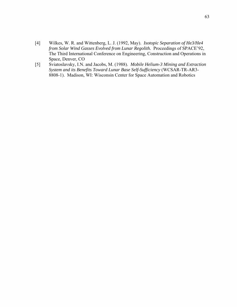
63
[4] Wilkes, W. R. and Wittenberg, L. J. (1992, May). Isotopic Separation of He3/He4
from Solar Wind Gasses Evolved from Lunar Regolith. Proceedings of SPACE�92, The Third International Conference on Engineering, Construction and Operations in Space, Denver, CO
[5] Sviatoslavsky, I.N. and Jacobs, M. (1988). Mobile Helium-3 Mining and Extraction System and its Benefits Toward Lunar Base Self-Sufficiency (WCSAR-TR-AR3-8808-1). Madison, WI: Wisconsin Center for Space Automation and Robotics
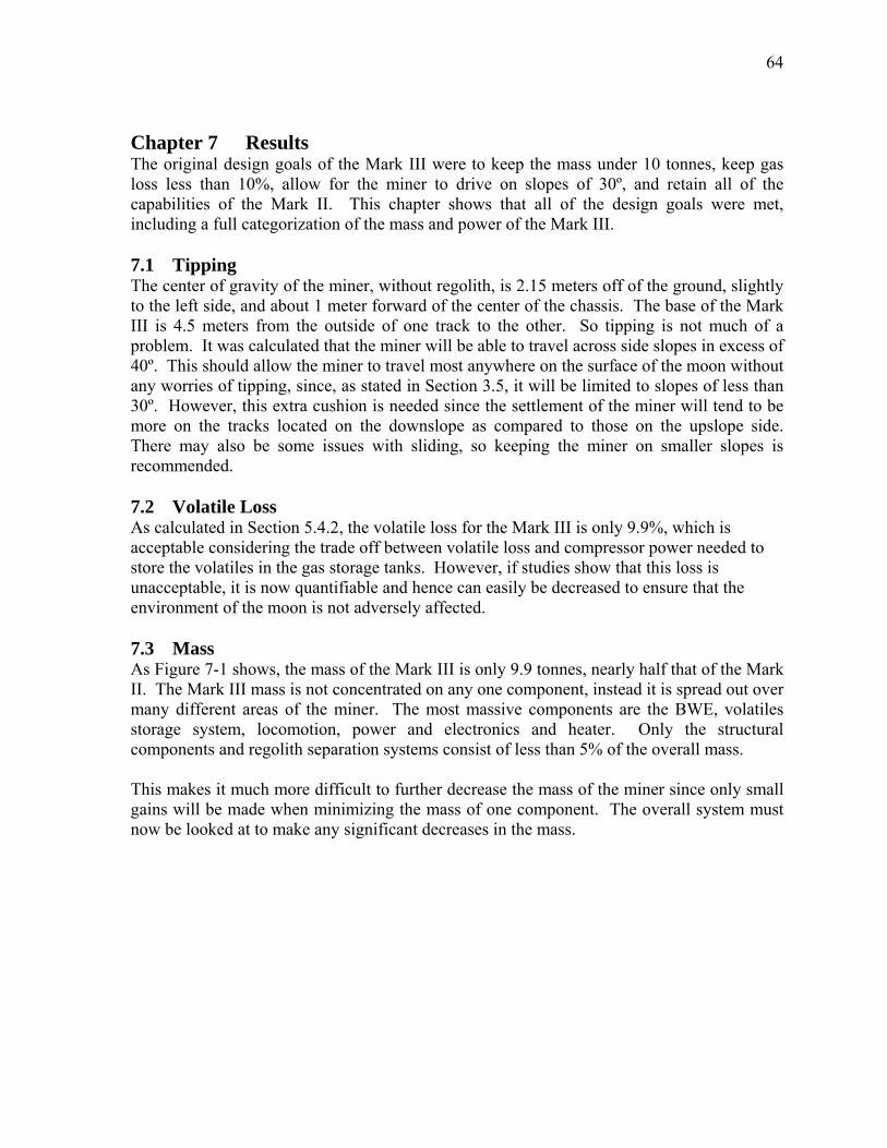
64
Chapter 7 Results The original design goals of the Mark III were to keep the mass under 10 tonnes, keep gas loss less than 10%, allow for the miner to drive on slopes of 30º, and retain all of the capabilities of the Mark II. This chapter shows that all of the design goals were met, including a full categorization of the mass and power of the Mark III. 7.1 Tipping The center of gravity of the miner, without regolith, is 2.15 meters off of the ground, slightly to the left side, and about 1 meter forward of the center of the chassis. The base of the Mark III is 4.5 meters from the outside of one track to the other. So tipping is not much of a problem. It was calculated that the miner will be able to travel across side slopes in excess of 40º. This should allow the miner to travel most anywhere on the surface of the moon without any worries of tipping, since, as stated in Section 3.5, it will be limited to slopes of less than 30º. However, this extra cushion is needed since the settlement of the miner will tend to be more on the tracks located on the downslope as compared to those on the upslope side. There may also be some issues with sliding, so keeping the miner on smaller slopes is recommended. 7.2 Volatile Loss As calculated in Section 5.4.2, the volatile loss for the Mark III is only 9.9%, which is acceptable considering the trade off between volatile loss and compressor power needed to store the volatiles in the gas storage tanks. However, if studies show that this loss is unacceptable, it is now quantifiable and hence can easily be decreased to ensure that the environment of the moon is not adversely affected. 7.3 Mass As Figure 7-1 shows, the mass of the Mark III is only 9.9 tonnes, nearly half that of the Mark II. The Mark III mass is not concentrated on any one component, instead it is spread out over many different areas of the miner. The most massive components are the BWE, volatiles storage system, locomotion, power and electronics and heater. Only the structural components and regolith separation systems consist of less than 5% of the overall mass. This makes it much more difficult to further decrease the mass of the miner since only small gains will be made when minimizing the mass of one component. The overall system must now be looked at to make any significant decreases in the mass.
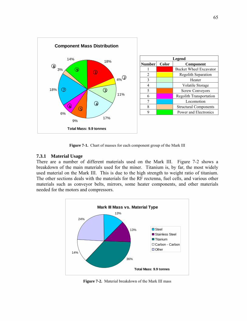
65
Component Mass Distribution
18%
4%
11%
17%9%
6%
18%
3%
14%
To ass: 9. nes
Legend Number Color Component
1 Bucket Wheel Excavator 2 Regolith Separation 3 Heater 4 Volatile Storage 5 Screw Conveyors 6 Regolith Transportation 7 Locomotion 8 Structural Components 9 Power and Electronics
8 9
1 2
7 3
465
tal M 9 ton
Figure 7-1. Chart of masses for each component group of the Mark III 7.3.1 Material Usage There are a number of different materials used on the Mark III. Figure 7-2 shows a breakdown of the main materials used for the miner. Titanium is, by far, the most widely used material on the Mark III. This is due to the high strength to weight ratio of titanium. The other sections deals with the materials for the RF rectenna, fuel cells, and various other materials such as conveyor belts, mirrors, some heater components, and other materials needed for the motors and compressors.
Mark III Mass vs. Material Type13%
13%
14%
24%
36%
SteelStainless SteelTitaniumCarbon - CarbonOther
Total Mass: 9.9 tonnes
Figure 7-2. Material breakdown of the Mark III mass
66
In general, titanium was preferred over steel due to the differences in mass. The main reasons for steel to be used at all is due to the hydrogen embrittlement that can happen to titanium. Because of this, titanium was generally not used for applications where the material would be in constant contact with the regolith. Although, this is generally not as much of an issue at lower temperatures, so for the more massive components, such as the BWE buckets, titanium was chosen over steel. This figure shows that most of the Mark III mass is contained in metallic materials, with only a some of the �other� materials being non-metals. The reason for this is simple; most all of the components of the Mark III are load bearing components and generally need to withstand fairly high stresses and in general, metals are better for these types of operations. Many of the components also come in direct contact with regolith, which is very abrasive and would quickly wear away any non-metal component. 7.3.2 Titanium Most all of the titanium used on the Mark III is Ti-6Al-4V since this specific type of titanium has one of the highest strength to weight ratios. It also has excellent fatigue strength hence is the most widely used titanium in industry. Figure 7-3 shows the other two types of titanium used on the Mark III. Ti-6Al-6V-2Sn can withstand higher shear stresses and is therefore used for the bucket wheel axle. The last type of titanium, Ti-6Al-2Sn-2Zr-2Mo-2Cr-0.25Si, was used for the BWE buckets, since it has a high fracture toughness and modulus of elasticity.
Different Types of Titanium Used
13%0%
87%
6Al-4V
6Al-2Sn-2Zr-2Mo-2Cr-0.25Si
6Al-6V-2Sn
Total Mass: 3575 kg Figure 7-3. Mass breakdown of the different types of titanium used
7.3.3 Steel Figure 7-4 shows that D-6a steel is the most widely used steel on the Mark III, composing of over half of the steel use on the miner. This steel was mainly used in the screw conveyors, due to the high impact strength, which is why it was also used for the teeth on the BWE. The
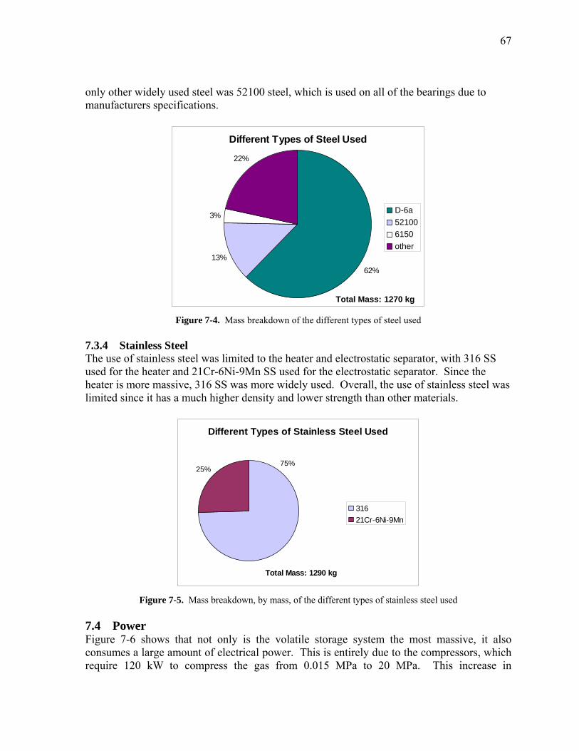
67
only other widely used steel was 52100 steel, which is used on all of the bearings due to manufacturers specifications.
Different Types of Steel Used
13%
3%
22%
62%
D-6a521006150other
Total Mass: 1270 kg Figure 7-4. Mass breakdown of the different types of steel used
7.3.4 Stainless Steel The use of stainless steel was limited to the heater and electrostatic separator, with 316 SS used for the heater and 21Cr-6Ni-9Mn SS used for the electrostatic separator. Since the heater is more massive, 316 SS was more widely used. Overall, the use of stainless steel was limited since it has a much higher density and lower strength than other materials.
Different Types of Stainless Steel Used
25%75%
31621Cr-6Ni-9Mn
Total Mass: 1290 kg
Figure 7-5. Mass breakdown, by mass, of the different types of stainless steel used
7.4 Power Figure 7-6 shows that not only is the volatile storage system the most massive, it also consumes a large amount of electrical power. This is entirely due to the compressors, which require 120 kW to compress the gas from 0.015 MPa to 20 MPa. This increase in
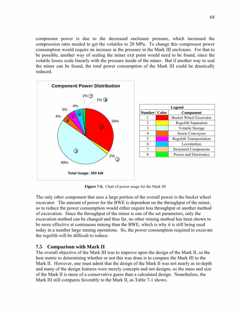
68
compressor power is due to the decreased enclosure pressure, which increased the compression ratio needed to get the volatiles to 20 MPa. To change this compressor power consumption would require an increase in the pressure in the Mark III enclosure. For that to be possible, another way of sealing the miner exit point would need to be found, since the volatile losses scale linearly with the pressure inside of the miner. But if another way to seal the miner can be found, the total power consumption of the Mark III could be drastically reduced.
Component Power Distribution
34%
2%
49%
4%
5%4%
1%1%
Total Usage: 350 kW
7 8
Legend Number Color Component
1 Bucket Wheel Excavator 2 Regolith Separation 3 Volatile Storage 4 Screw Conveyors 5 Regolith Transportation 6 Locomotion 7 Structural Components 8 Power and Electronics
6 5 4
1
3
2
Figure 7-6. Chart of power usage for the Mark III The only other component that uses a large portion of the overall power is the bucket wheel excavator. The amount of power for the BWE is dependent on the throughput of the miner, so to reduce the power consumption would either require less throughput or another method of excavation. Since the throughput of the miner is one of the set parameters, only the excavation method can be changed and thus far, no other mining method has been shown to be more effective at continuous mining than the BWE, which is why it is still being used today in a number large mining operations. So, the power consumption required to excavate the regolith will be difficult to reduce. 7.5 Comparison with Mark II The overall objective of the Mark III was to improve upon the design of the Mark II, so the best metric to determining whether or not this was done is to compare the Mark III to the Mark II. However, one must admit that the design of the Mark II was not nearly as in-depth and many of the design features were merely concepts and not designs, so the mass and size of the Mark II is more of a conservative guess than a calculated design. Nonetheless, the Mark III still compares favorably to the Mark II, as Table 7-1 shows.
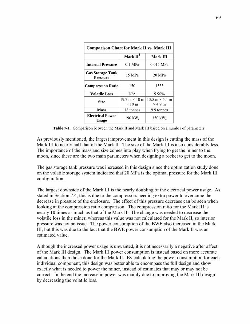
69
Comparison Chart for Mark II vs. Mark III
Mark II1 Mark III
Internal Pressure 0.1 MPa 0.015 MPa
Gas Storage Tank Pressure 15 MPa 20 MPa
Compression Ratio 150 1333
Volatile Loss N/A 9.90%
Size 19.7 m × 10 m × 10 m
13.5 m × 5.4 m × 4.9 m
Mass 18 tonnes 9.9 tonnes Electrical Power
Usage 190 kWe 350 kWe
Table 7-1. Comparison between the Mark II and Mark III based on a number of parameters As previously mentioned, the largest improvement in this design is cutting the mass of the Mark III to nearly half that of the Mark II. The size of the Mark III is also considerably less. The importance of the mass and size comes into play when trying to get the miner to the moon, since these are the two main parameters when designing a rocket to get to the moon. The gas storage tank pressure was increased in this design since the optimization study done on the volatile storage system indicated that 20 MPa is the optimal pressure for the Mark III configuration. The largest downside of the Mark III is the nearly doubling of the electrical power usage. As stated in Section 7.4, this is due to the compressors needing extra power to overcome the decrease in pressure of the enclosure. The effect of this pressure decrease can be seen when looking at the compression ratio comparison. The compression ratio for the Mark III is nearly 10 times as much as that of the Mark II. The change was needed to decrease the volatile loss in the miner, whereas this value was not calculated for the Mark II, so interior pressure was not an issue. The power consumption of the BWE also increased in the Mark III, but this was due to the fact that the BWE power consumption of the Mark II was an estimated value. Although the increased power usage is unwanted, it is not necessarily a negative after affect of the Mark III design. The Mark III power consumption is instead based on more accurate calculations than those done for the Mark II. By calculating the power consumption for each individual component, this design was better able to encompass the full design and show exactly what is needed to power the miner, instead of estimates that may or may not be correct. In the end the increase in power was mainly due to improving the Mark III design by decreasing the volatile loss.
70
Overall, it can be seen that the design of the Mark III compares favorably with that of the Mark II. The only unwanted change was the increase in power usage, but that was unavoidable. The mass and size were both nearly cut in half, while the Mark III still retained all of the capabilities of the Mark II. 7.6 References [1] Sviatoslavsky, I. N. and Jacobs, M. (1988). Mobile Helium-3 Mining and Extraction System and its Benefits Toward Lunar Base Self-Sufficiency (WCSAR-TR-AR3-8808-1). Madison, WI: Wisconsin Center for Space Automation and Robotics
71
Chapter 8 Mining Issues Even though the Mark III design is complete, there are still some issues that need to be worked out. Some of these issues will require more information, others depend on advancing technologies, but all of these questions will need to be answered before any future miner design is to travel the lunar surface. 8.1 Gas Extraction If more gas is extracted than expected, the compressors will not be able to handle the flow rate. All of the other components should operate normally, except the gas tanks will fill faster than normal. This is why more information is needed on exactly how much gas will be extracted. Once this is known, the compressors can be chosen so that this will not be as much of an issue. However, this will still be an issue since there will be deviations throughout the regolith, so the mining speed may need to be slowed down to let the compressors catch up with the extracted volatiles. 8.2 Mass Flow Rates It is impossible to know what the exact size distribution of the regolith will be throughout the mining area, the regolith flow rates throughout the miner will vary with every scoop of the bucket wheel. So there will need to be sensors through the miner that detect the different flow rates throughout the Mark III. The signals from these sensors will then be used to speed up or slow down the mining operations depending on if bottlenecks are occurring in the system. The conveyors are designed to handle more regolith than is expected, however, there are limitations. This system could be complicated, but in the end it would ensure that there is a steady flow of regolith going through the Mark III. 8.3 Dust On earth, we think of dust as particles floating in the air that eventually cover everything. This is not the case on the moon, the dust particles have no atmosphere or air current to keep them floating. The particles will instead follow a ballistic trajectory until they come back to rest on a surface, whether it be the moon or mining equipment. The only exception to this is static electricity, which can lift dust particles from the lunar surface1, especially when the terminator crosses. But as long as the miner is not left outside uncovered during this time, there should be no problems. A ballistics calculation on the regolith inside of the bucket wheel shows that the regolith particles will not come within 4 meters of the solar collector. This is assuming the worst case scenario of a particle moving at the speed of the bucket wheel, with the optimal angle needed to get to the bottom of the solar collector. To be able to reach the solar collector, the particle would need to be traveling 3 times faster than the bucket wheel just to reach the bottom of the solar collector, which is not a practical situation. However, in general, dust will cover some of the Mark III components, especially the bucket wheel, and will need to be cleaned off. Similarly, the regolith thrown by the ejection mechanism will never be thrown towards the collector and hence will not be a problem.
72
8.4 Material Embrittlement A lot of caution was taken in the design of the Mark III to minimize the hydrogen embrittlement of titanium. Titanium only exhibits hydrogen embrittlement at elevated temperatures2, so wherever high temperatures are encountered, either a different material was used, or a type of titanium that does not exhibit embrittlement was used. There are also coatings that can be used to protect the titanium, which is an area that needs to be investigated for future miner designs. Yet to be solved is the issue of what material should be used for the conveyor belts. The main material for today�s conveyor belts is rubber, but with the radiation in space, the rubber will become brittle and eventually crack and fall apart. The belts used for the Mark III, will be made from steel reinforced rubber. So a new material needs to be found that is both flexible and radiation resistant. 8.5 Material Erosion Due to the abrasive nature of the regolith, any component that is in constant contact with the regolith will have a tendency to erode. The main components that this will be a problem for will be the buckets, slide, screw conveyors, fluidized chamber, and heater. Basic maintenance will be able to take care of most of the components, ensuring that the wear will not threaten the mining operations, but this will be very difficult to do with the heater. There are about 25000 heat pipes in the heater, which makes it very difficult to inspect to inspect the heater and even harder to replace heat pipes on the interior of the heater. The heater is much to large to be able to replace the entire component, so great caution will be needed to be taken in the manufacturing of the heater to ensure that the heater will consist of a number of sections that, when assembled, form the heater. This will allow maintenance crews to easily disassemble and inspect the individual sections of the heater and if there is a problem in one section of the heater then just that section can be replaced, while the removed section is fixed. Without this modularity, the heater would be unable to be maintained. 8.6 References [1] Heiken, Grant H., Vaniman, David T., French, Bevan M. (1991). Lunar Sourcebook,
a user’s guide to the moon. Cambridge : Cambridge University [2] ASM Handbook, Volume 11. (2003). Materials Park, OH : ASM International
73
Chapter 9 Recommended Future Work While designing the Mark III, many ideas and concepts came along that were not in the scope of this design. These ideas will need to be taken into consideration for future miner designs. 9.1 Safety Factor All of the structural calculations were done assuming a safety factor of 2. Most space structures built today use a safety factor of at most 1.5 and usually nearly 1. Such a high safety factor was used since many of the calculations were of first order and therefore were not exact. To make up for this, a conservative safety factor was used when determining the final mass of the miner. However, further calculations have shown that the mass of the miner will drop to 8.6 tonnes for a safety factor of 1.5 and 7.5 tonnes for a safety factor of 1. This shows that it should be possible to cut the mass of the miner by a significant amount with a much more in-depth analysis, given that the assumptions made are not too optimistic. 9.2 Continuous Mining The obvious advantage to continuous mining is that the miner will be operating for longer periods of time and therefore extract more volatiles. However, with this approach, much redesigning must be done. There are two main options, either have relay stations on or in orbit around the moon to beam solar energy to the miner keeping the Mark III design, or have another source of energy and alter the design. This other source of energy could be nuclear, fuel cells, or batteries. The regolith could then be heated by using microwaves to excite the nanophase iron in the regolith and therefore heat the regolith1. One big problem with continuous mining is that there will still be a considerable amount of down-time for maintenance reasons. There is also the issue of the terminator that could possibly cover the miner in a fine layer of dust, but the miner could be covered during these times. It is possible to transform the Mark III into a continuous miner, actually, most of the changes will be in the infrastructure required to support mining operations, which become much more complex when switching to continuous mining operations. So the Mark III could either be used as is, or slight modifications could be done to allow for continuous mining. 9.3 Power Sources Although solar was chosen as the power source for the Mark III, there are many other options. 9.3.1 Nuclear Instead of using converted solar power for the RF beaming, it would also be possible to use a nuclear reactor. Settlements on the moon may use nuclear power for the main power supply. If this is done, then the same nuclear power could also be used to help power the miner. 9.3.2 Thermophotovoltaics The array of photovoltaic cells could also be replaced with an array of thermophotovoltaics (TPV�s). TPV�s have efficiencies as high as 30% and are not nearly as temperature dependent as PV cells2. So the radiators needed for the TPV�s would not need to be as large,
74
however this is an issue that will need to be decided down the road, since it is difficult to say where these technologies will be in 10+ years when mining the moon could at last become a reality. 9.3.3 Power Cord Another possible way to get power to the miner is to use a power transmission cord. This idea is a little unconventional, but because the Mark III is moving so slowly, it is feasible. The difficultly would be that many kilometers of cable would be needed, which will have a fairly high mass. A trade-study would need to be done between the mass of the cable and the mass of the RF beaming system. 9.4 Design Changes As technologies evolve and newer concepts become available, future miner designs will also need to evolve, some of these evolutions are described below. Also, some of the design components will need the expertise of mining engineers to fully develop the Mark III. 9.4.1 Bucket Wheel Excavator One area that could definitely use some improvement is the bucket wheel excavator. Although all of the calculations done for the BWE are from a reputable mining book, the actual design of the BWE needs to be designed by a mining company, since only so much information can be found in the book. To design such a complicated piece of machinery requires decades of experience and a worst scale model simulations. So for future versions of the miner, it would be wise to have the expertise of engineers who built today�s large mining machines. One group of engineers working on this problem is at the Colorado School of Mines. Muff, Johnson, King, and Duke3 designed and tested a scale model of a bucket wheel excavator. The experiment calculated the power required to dig up a sand-gravel mixture, with differing compactness and processing rates. The sand-gravel mixture was chosen to mimic the regolith densities estimated from the Viking mission. Their experiments gave them much insight into improving their design to become more efficient and how to best optimize the production rate while reducing the mass. These are the types of experiments that must be done before any miner reaches the moon. Without these studies, it is impossible to optimize the BWE design. 9.4.2 Power One way to utilize the high temperatures in the heater would be to line the heater walls with thermophotovoltaics. Some of the heat from the heater would be converted into energy that could then be used for electrical power. This would cut down on the amount of beamed power that would be needed for the Mark III. Doing this would not adversely affect the performance of the heater since very little of the heat would be used with the TPV�s while the rest would be waste heat used to heat the regolith. The largest difficulty with this idea is that the backside of the cell will need to be cooled to allow for higher efficiencies.
75
9.4.3 Regolith Heating 9.4.3.1 Fluidized Bed Another possible way to heat the regolith would be to use convection in the fluidized bed. A recent study by Nayagam and Sacksteder4 looked into using a fluidized bed to heat a lunar regolith simulant to extract volatiles. Although this study looked at leaving the simulant in a fluidized bed for a long period of time to extract volatiles, it showed that it is possible to heat up the regolith in a fluidized bed using a heated gas. So if the volatile gas were heated enough before entering the fluidized bed, it would be possible to reduce the energy needed in the heater or possibly even remove the heater, although this would require for a very high gas temperature and a slow moving fluidized bed. However, if this technology could reduce the size and/or mass of the heater by a small fraction, it would be worth it since the heater is one of the more massive parts on the Mark III. 9.4.3.2 Radio Frequency A paper by Taylor and Meek5 discusses using RF waves to heat up the lunar regolith. This works since there is nanophase Fe0 in the lunar soil, which absorbs the microwave energy, thereby causing the nanophase Fe0 to heat up. The advantages of using this technology compared to the heater on the Mark III is that microwave heating has very rapid heating rates and can have a tremendous energy savings, upwards of 100% according to Taylor and Meek. However, when using this method, there can be large temperature gradient, on the order of 100�s of degree Celsius. With the superposition of multiple frequencies, it is believed that this can be overcome, but the process is very complex and will require extra research. If this can be accomplished, then it very well may be much more efficient to use microwave heating in place of the current heater on the Mark III. 9.4.4 Vacuum Seal When looking at the power distribution, it is quite obvious that there must be a way to reduce the amount of power needed for the compressors. However, to do this and still keep the volatile losses below 10%, a different method must be found for the vacuum seal, especially at the regolith exit. If there is a way to efficiently seal the interior of the Mark III from the lunar vacuum, then the interior pressure of the Mark III could be higher, which would allow for a lower compression ratio and hence a lower power usage. 9.4.5 Optics As described in Section 4.2, the concentrated solar beams will not be exactly parallel, but will instead be slightly focused since white light tends to become dispersed when beamed. This will require very complex optics since the focus of this light been will need to be changed depending on the distance between the miner and the large stationary dish. There will also need to be a system that controls the stationary solar collector mirrors so that the focused solar beam will always be pointing towards the solar collector mounted on the miner. The last step towards improving the optics for the Mark III will be to have deployable parabolic dishes instead of modular designs for the dishes. There is a lot of current research being done on deployable dishes6,7,8,9, and using such a dish should lead to much lighter parabolic dishes for the solar collectors.
76
9.5 Agitation Agitation is one area that needs a lot of attention before a final miner design is decided upon. Schmitt10 believes that up to 42% of the 3He, along with a fraction of the other volatiles, was lost from the lunar soil, collected from the Apollo missions, before it got back to the Earth. He thinks that by handling the regolith, much of the trapped volatiles are released. If this is the case, then any future miner should take advantage of this to release the volatiles. The Mark III is designed to limit the losses due to agitation, but it is not designed to take advantage of the agitation. If Schmitt is correct, then the miner would not need to excavate nearly as much regolith to get the desired output of volatiles, which could drastically reduce the size and mass of the miner. Or the agitation could be used to extract the volatiles without heating the regolith, which would greatly simplify the process. But before any of this is done, further studies need to be done to determine how much of an affect agitation has on the recovery of lunar volatiles. 9.6 Properties of the Regolith To be able to more accurately predict the amount of energy needed to excavate, beneficiate, and heat the regolith, more precise measurements of the properties of the regolith are needed. Right now a lot of these properties just estimates or guesses. A more thorough set of experiments will need to be done either on the moon or using lunar simulants. Along with this, experiments should be conducted on lunar simulants to mimic the processes of the Mark III. These experiments will give a much better idea of what should be expected on the moon. However they will not be able to answer some questions, such as how hard packed the regolith will be and whether or not it will clump. If the regolith is clumped up and does not flow smoothly, it will cause problems with the seal at the screw conveyors. It would also be helpful to know more precisely the amount of volatiles entrained in the regolith. Many people, including Schmitt10 believe that a large percentage of the volatiles were lost when transferring the regolith from the moon to Earth. If this is the case, then much of what we know about the volatiles in the regolith is incorrect. A new set of data needs to be taken that accurately measures the volatile content of the regolith. A recent issue brought up by Lawrence A. Taylor (personal communication, February 15, 2006) has been whether or not the regolith will react with the water vapor once it is extracted from the regolith. This is a very new issue and has yet to be fully researched, but is yet another area that needs more work. This information will guide the future designs of the lunar miner, without them, new designs will not be able to account for the unique properties of the lunar regolith. 9.7 Dust There is no doubt that one way or another, dust will get on the miner and all of the support equipment. What needs to be figured out is a way to clean the dust off to ensure that it does not cause heating or abrasion problems.
77
Also, a significant issue that does not directly affect the miner, but still needs to be addressed is the health affects of the dust on humans. People believe that if enough dust is inhaled into the lungs, it could be deadly11. One thing is for sure, the health issues associated with lunar dust need to be researched before a humans inhabit the moon. Along with this, research will need to be done to develop dust seals for the lunar habitats. 9.8 Spiral Mining Another concept for mining the moon was done in the early 1990�s at the University of Wisconsin studied a spiral mining concept12. The miner for this architecture was to be based on the Mark II design. The proposed miner would excavate, beneficiate, and extract the solar wind volatiles. The difference would be that the miner would be attached to a telescoping arm that would connect the miner to a central station that the volatiles would be pumped to once extracted. The electrical power for the miner would come from this central station, thus eliminating the need for beamed energy to provide electricity. This would also eliminate the need for storage tanks, compressors, and intercoolers on the miner, thus simplifying the miner, since all of the gas processing would be done at the central station. The miner would travel in a spiral around the central station, with the telescoping arm extending to allow the gasses to be continuously pumped to the central station. Once the arm became fully extended, the central station would be moved to a new location where mining operations would continue. This process does not inherently change the design of the Mark III since most of the components of the miner are still required. This design concept is mainly another possible way to mine the lunar volatiles instead of the traditional rectilinear mining that is done in surface mines of Earth. However, it should be mentioned that there are other mining architectures that are not considered to be useful on Earth, but yet could be feasible on the moon, so one must not have a narrow focus when considering lunar mining. 9.9 Extracting Metallics One possible extension of the Mark III miner is to reprocess the regolith fines to extract the metallic materials (Fe, Ti, Al, Mg, Ni, etc.)13 contained in the regolith. This process would not be done on the Mark III, but the regolith fines could be conveyed to another machine that would be capable of extracting the metallics from the regolith. This would save energy since the metallic extracting machine would not need to excavate or beneficiate the regolith. This is quite feasible, but still needs much more work before it can be implemented into a design. 9.10 References [1] Taylor, L. A. (2004). Lunar Soil for a Myriad of Purposes and Products: Science,
Engineering, and Applications. NEEP 533: University of Wisconsin � Madison, retrieved from fti.neep.wisc.edu/neep533/SPRING2004/lecture11.pdf on February 22, 2006
78
[2] Teofilo, V. L., Choong, P., Chen, W., Chang, J., Tseng, Y-L. (2006 February).
Thermophotovoltaic Energy Conversion for Space Applications. Proceedings of the Space Technology and Application International Forum � STAIF 2006, Albuquerque, NM
[3] Muff, T., Johnson, L., King, R., Duke, M. B. (2004 February). A Prototype Bucket Wheel Excavator for the Moon, Mars and Phobos. Proceedings of the Space technology and Applications International Forum � STAIF 2004, Albuquerque, NM
[4] Nayagam, V., Sacksteder, K. R. (2006 February). A Vibrofluidized Reactor for Resource Extraction from Lunar Regolith. Proceedings of the Space technology and Applications International Forum � STAIF 2006, Albuquerque, NM
[5] Taylor, L. A., Meek, T. T. (2005). Microwave Sintering of Lunar Soil: Properties, Theory, and Practice. Journal of Aerospace Engineering, 18(3), 188-196
[6] Tan, L. T. (2006 March). Deployable Reflector Antennas with Doubly Curved Stiffeners. Paper presented at Earth & Space 2006, The 10th Biennial Conference on Engineering, Construction, and Operation in Challenging Environments
[7] Williams, R. B., Klein, K, J, Agnes, G. S. (2006 March). Vibration of a Singly-Curved Thin Shell Reflector with a Unidirectional Tension Field. Paper presented at Earth & Space 2006, The 10th Biennial Conference on Engineering, Construction, and Operation in Challenging Environments
[8] Medzmariashvili, E., Tserodze, Sh., Tsignadze, N., Sanikidze, M., Datashivili, L., Sarchimelia, A., et al. (2006 March). A New Design Variant of the Large Deployable Space Reflector. Proceedings of Earth & Space 2006, The 10th Biennial Conference on Engineering, Construction, and Operation in Challenging Environments
[9] Datashivili, L., Baier, H. (2006 March). Membranes and Thin Shells for Space Reflectors. Proceedings of Earth & Space 2006, The 10th Biennial Conference on Engineering, Construction, and Operation in Challenging Environments
[10] Schmitt, H. H. (2006). Return to the Moon. New York: Copernicus Books [11] Flinn, E. D. (2006, February 23). Solving Settlement Problems: Dealing with Moon
Dust. SPACE.com. Retrieved February 28, 2006, from http://www.space.com/adastra/adastra_moondust_060223.html
[12] Schmitt, H. H., Kulcinski, G. L., Sviatoslavsky, I. N., Carrier, W. D. (1992 March). Spiral Mining for Lunar Volatiles. Proceedings of Space 92, The 3rd International Conference and Exposition of Engineering, Construction and Operations in Space, Denver, CO
[13] Heiken, Grant H., Vaniman, David T., French, Bevan M. (1991). Lunar Sourcebook, a user’s guide to the moon. Cambridge : Cambridge University
79
Chapter 10 Conclusion In the end, the main goals of this research were met. The mass of the miner is 9.9 tonnes, less than the required 10 tonnes and half the mass of the Mark II, and it has been shown that this miner will be able to fit into rockets that, in the future, can send it to the moon. All of this was done while retaining the capabilities of the Mark II. More importantly, this thesis confirmed that it is feasible to use a lunar volatiles miner to support a base on the moon. Once the infrastructure is set up, it will be must less expensive to mine the lunar surface for volatiles for life support than by sending rockets from Earth. This thesis also Along with finding the mass and size, 13.5 x 5.4 x 4.9 meters, the electrical power required for the Mark III was found to be 350 kW. These numbers give a baseline for future lunar volatiles miners. However, this thesis not only went over the design of the Mark III, it also discusses what equipment and facilities would be needed to support mining operations. And quite possibly the most useful information in this thesis for future use will be the sections on mining issues and recommended future work. This thesis mentions a number of areas that must be improved upon, or at least studied, to significantly improve upon the Mark III design. Some of these improvements relate directly to the Mark III design, while others are more general improvements needed before any miner reaches the lunar surface. Along with this, a number of future projects are also mentioned. These projects are not only for improving the information base for lunar mining, but are also required for inhabiting the moon. Some of this work has already been started, while the remaining studies must be done before a complex miner can be fully designed. One set of information that will make it much easier for future designs is the categorized mass and power. This information shows which components are the most massive and which ones use up the most electrical power, which makes is possible to see the most efficient ways of improving upon the Mark III design. The materials used on the Mark III components are also categorized, so if somebody wants to replace on material with another, they can see about how much mass can be saved from that replacement. So this thesis is not only on the design of the Mark III miner and proving the feasibility of supporting a lunar base with a lunar volatiles miner, it also gives a blueprint on how to best improve upon the Mark III design. This thesis describes the areas in which more information is needed for future miner designs and for lunar habitation in general. This is very valuable information when deciding which missions must be done and what information is needed before inhabiting the moon.
80
Appendix A Mineable Area A.1 Mineable Area To mine the moon, one must be able to determine which areas of the moon are mineable, i.e. are not full of craters, ridges, rocks, and other unmineable features. One way to do this would be to take a map of an area of the moon and mark out all of the unmineable areas and then determine which areas are large enough to be mined. This trade study, dependent on the minimum feasible mine size and the capability of the miner to avoid objects, was done for Mare Tranquillitis by Cameron and Kulcinski1. This study looked at 27 high-resolution photographs, 2-meter resolution, taken during previous missions to the moon. These photographs spanned an area of about 100 square kilometers. Before mapping out these photos, Cameron and Kulcinski had to determine which features of the lunar surface are mineable. The main part of this research deals with craters and their associated ejecta halos, which may contain rocks that would be unable to be mined by the Mark III. Cameron and Kulcinski reported that the average depth to diameter ratio of fresh craters was 0.25 and that the average depth of the regolith away from craters larger than 12 meters in diameter was at least 3 meters. So craters with diameters less than 12 meters should not have reached bedrock and therefore will not have rocky ejecta halos. Since most of the craters on the lunar surface are less than 12 meters in diameter, this leaves a good portion of the surface to be mined. The distinction between fresh craters and very old craters is quite substantial, since very old craters only cause slight undulations on the lunar surface and should have been exposed to enough solar wind volatiles to cover the upper 3 meters with regolith. But Cameron and Kulcinski took a very conservative approach with these types of craters since it is very difficult to distinguish between the old craters and the new craters based only on photographs, so even the old craters were determined to be unmineable. The next step in this paper was to determine how large the ejecta halos extended out from the crater rim. This could not be done only from the photographs since only rocks larger than 2 meters in diameter could be seen. For this, the advice of Harrison H. Schmitt was taken. Schmitt stated that if no 2-meter blocks of rock are found, the unmineable area is a circle centered on the crater with the diameter equal to the crater diameter. If blocks are only visible inside the crater, the unmineable area is a circle with a diameter twice that of the crater and if the blocks are outside of the crater, the unmineable area is a circle with a diameter three times that of the crater. Their analysis showed that the area covered by craters and ejecta halo ranged from 8.5% to 50.4% depending on the photograph, with the average being 16.4%. However, this does not mean that it is feasible to mine 83.6% of the area. It is not practical to mine a very small area since the effort to mine small areas would not be worth the relatively small amount of volatiles recovered. So Cameron and Kulcinski did a trade study on one of the photographs
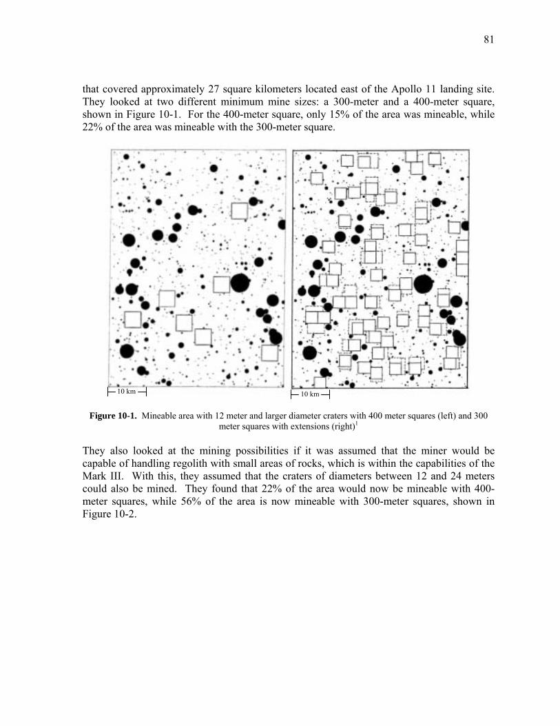
81
that covered approximately 27 square kilometers located east of the Apollo 11 landing site. They looked at two different minimum mine sizes: a 300-meter and a 400-meter square, shown in Figure 10-1. For the 400-meter square, only 15% of the area was mineable, while 22% of the area was mineable with the 300-meter square.
10 km10 km
Figure 10-1. Mineable area with 12 meter and larger diameter craters with 400 meter squares (left) and 300 meter squares with extensions (right)1
They also looked at the mining possibilities if it was assumed that the miner would be capable of handling regolith with small areas of rocks, which is within the capabilities of the Mark III. With this, they assumed that the craters of diameters between 12 and 24 meters could also be mined. They found that 22% of the area would now be mineable with 400-meter squares, while 56% of the area is now mineable with 300-meter squares, shown in Figure 10-2.
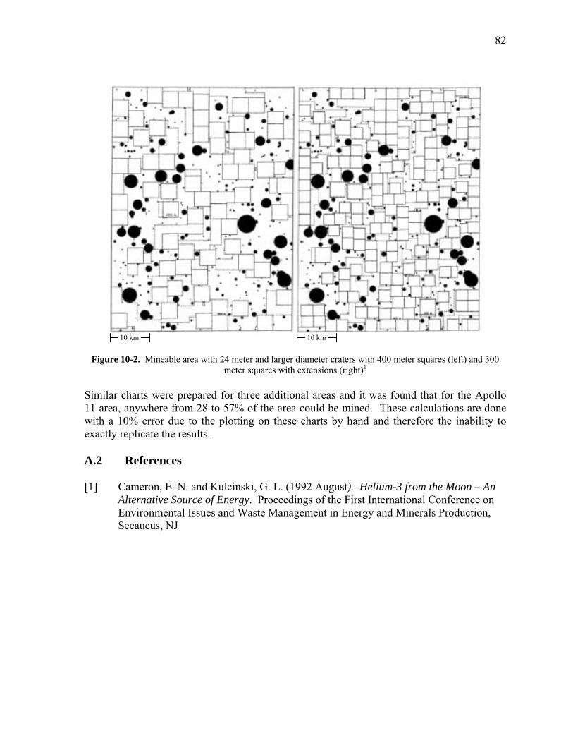
82
10 km 10 km
Figure 10-2. Mineable area with 24 meter and larger diameter craters with 400 meter squares (left) and 300 meter squares with extensions (right)1
Similar charts were prepared for three additional areas and it was found that for the Apollo 11 area, anywhere from 28 to 57% of the area could be mined. These calculations are done with a 10% error due to the plotting on these charts by hand and therefore the inability to exactly replicate the results. A.2 References [1] Cameron, E. N. and Kulcinski, G. L. (1992 August). Helium-3 from the Moon – An
Alternative Source of Energy. Proceedings of the First International Conference on Environmental Issues and Waste Management in Energy and Minerals Production, Secaucus, NJ
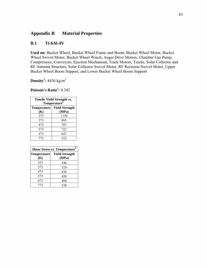
83
Appendix B Material Properties B.1 Ti-6Al-4V Used on: Bucket Wheel, Bucket Wheel Frame and Boom, Bucket Wheel Motor, Bucket Wheel Swivel Motor, Bucket Wheel Winch, Auger Drive Motors, Chamber Gas Pump, Compressors, Conveyors, Ejection Mechanism, Track Motors, Tracks, Solar Collector and RF Antenna Structure, Solar Collector Swivel Motor, RF Rectenna Swivel Motor, Upper Bucket Wheel Boom Support, and Lower Bucket Wheel Boom Support Density1: 4430 kg/m3 Poisson’s Ratio : 0.342 1
Tensile Yield Strength vs.
Temperature1 Temperature
(K) Yield Strength
(MPa) 273 1130 373 895 473 797 573 722 673 647 773 532
Shear Stress vs. Temperature2
Temperature (K)
Yield Strength (MPa)
323 546 373 524 473 436 573 420 673 404 773 338
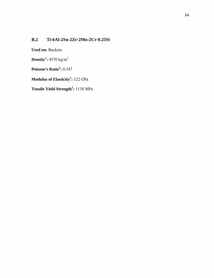
84
B.2 Ti-6Al-2Sn-2Zr-2Mo-2Cr-0.25Si Used on: Buckets Density1: 4570 kg/m3 Poisson’s Ratio1: 0.347 Modulus of Elasticity1: 122 GPa Tensile Yield Strength1: 1138 MPa
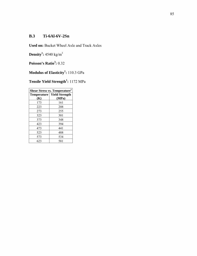
85
B.3 Ti-6Al-6V-2Sn Used on: Bucket Wheel Axle and Track Axles Density1: 4540 kg/m3 Poisson’s Ratio3: 0.32 Modulus of Elasticity1: 110.3 GPa Tensile Yield Strength1: 1172 MPa Shear Stress vs. Temperature2 Temperature
(K) Yield Strength
(MPa) 173 161 223 208 273 255 323 301 373 348 423 394 473 441 523 488 573 534 623 581
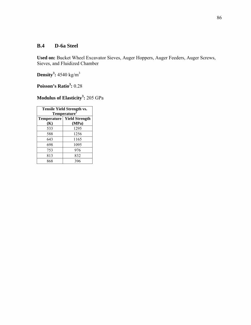
86
B.4 D-6a Steel Used on: Bucket Wheel Excavator Sieves, Auger Hoppers, Auger Feeders, Auger Screws, Sieves, and Fluidized Chamber Density3: 4540 kg/m3 Poisson’s Ratio3: 0.28 Modulus of Elasticity3: 205 GPa
Tensile Yield Strength vs. Temperature1
Temperature (K)
Yield Strength (MPa)
533 1295 588 1256 643 1165 698 1095 753 976 813 832 868 396
87
B.5 6150 Steel Used on: Fluidized Chamber, Slide to Conveyor, and Chute Density3: 7850 kg/m3 Poisson’s Ratio3: 0.29 Modulus of Elasticity3: 205 GPa Tensile Yield Strength3: 1225 MPa
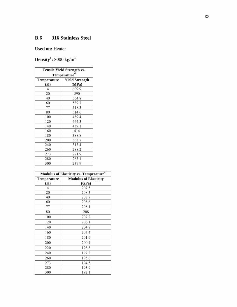
88
B.6 316 Stainless Steel Used on: Heater Density1: 8000 kg/m3
Tensile Yield Strength vs. Temperature4
Temperature (K)
Yield Strength (MPa)
4 609.9 20 590 40 564.8 60 539.7 77 518.3 80 514.6
100 489.4 120 464.3 140 439.1 160 414 180 388.8 200 363.7 240 313.4 260 288.2 273 271.9 280 263.1 300 237.9
Modulus of Elasticity vs. Temperature4
Temperature (K)
Modulus of Elasticity (GPa)
4 207.5 20 208.3 40 208.7 60 208.6 77 208.1 80 208
100 207.2 120 206.1 140 204.8 160 203.4 180 201.9 200 200.4 220 198.8 240 197.2 260 195.6 273 194.5 280 193.9 300 192.1
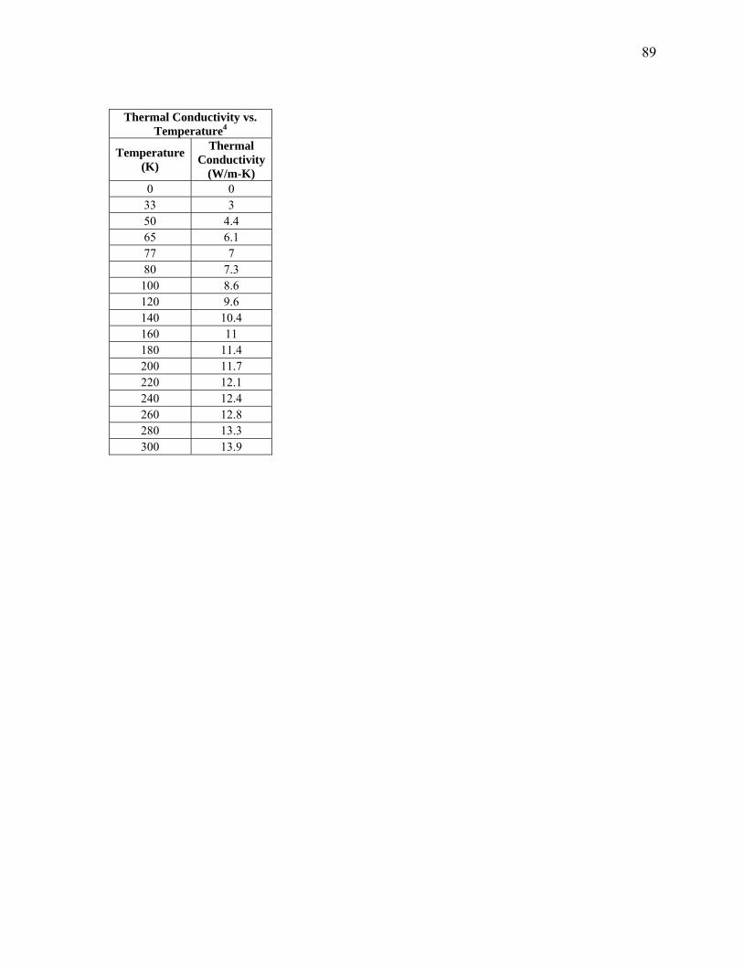
89
Thermal Conductivity vs. Temperature4
Temperature (K)
Thermal Conductivity
(W/m-K) 0 0
33 3 50 4.4 65 6.1 77 7 80 7.3
100 8.6 120 9.6 140 10.4 160 11 180 11.4 200 11.7 220 12.1 240 12.4 260 12.8 280 13.3 300 13.9
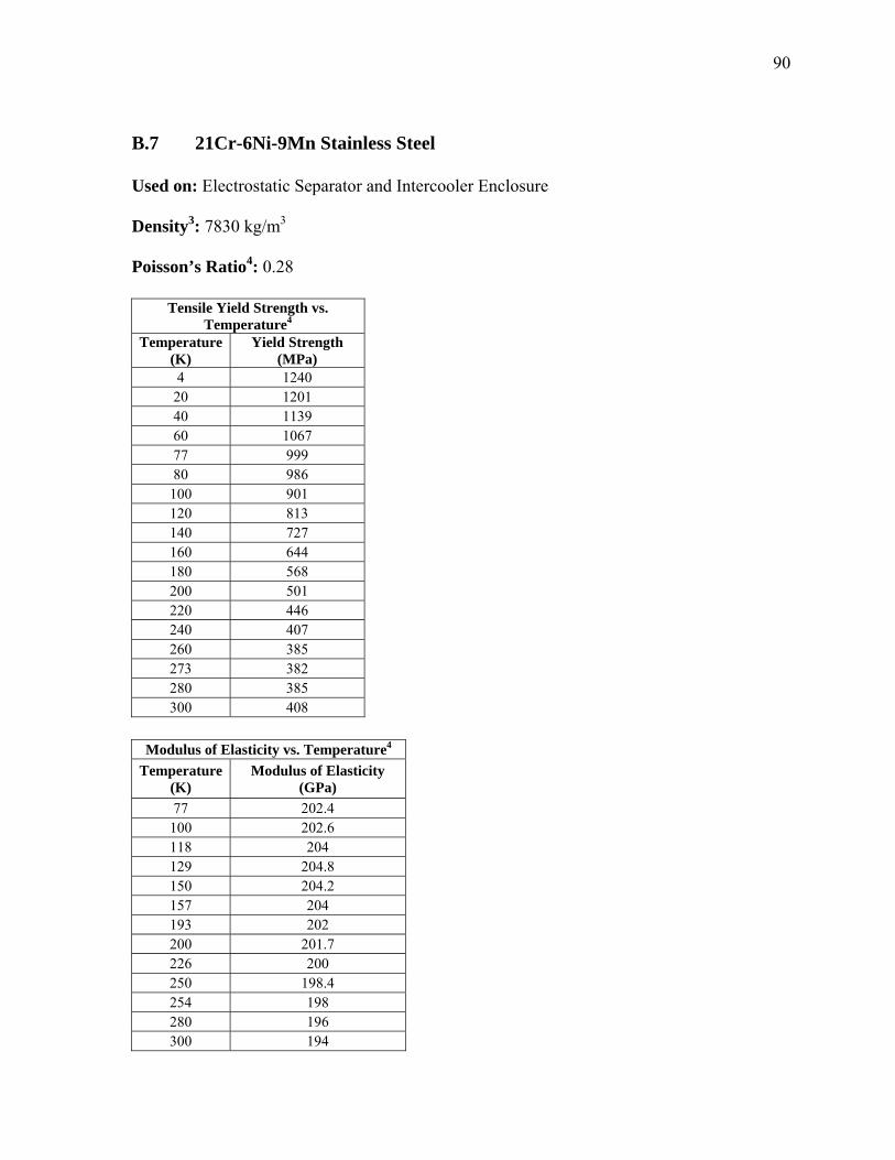
90
B.7 21Cr-6Ni-9Mn Stainless Steel Used on: Electrostatic Separator and Intercooler Enclosure Density3: 7830 kg/m3 Poisson’s Ratio4: 0.28
Tensile Yield Strength vs. Temperature4
Temperature (K)
Yield Strength (MPa)
4 1240 20 1201 40 1139 60 1067 77 999 80 986
100 901 120 813 140 727 160 644 180 568 200 501 220 446 240 407 260 385 273 382 280 385 300 408
Modulus of Elasticity vs. Temperature4
Temperature (K)
Modulus of Elasticity (GPa)
77 202.4 100 202.6 118 204 129 204.8 150 204.2 157 204 193 202 200 201.7 226 200 250 198.4 254 198 280 196 300 194
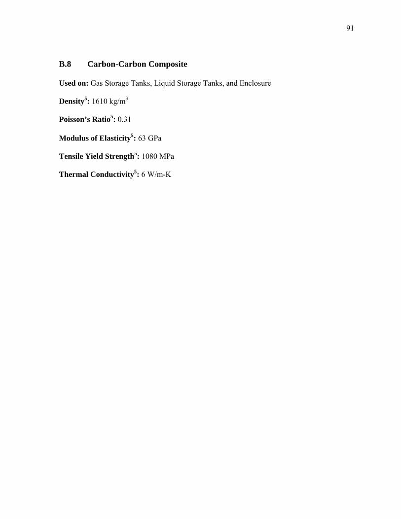
91
B.8 Carbon-Carbon Composite Used on: Gas Storage Tanks, Liquid Storage Tanks, and Enclosure Density5: 1610 kg/m3 Poisson’s Ratio5: 0.31 Modulus of Elasticity5: 63 GPa Tensile Yield Strength5: 1080 MPa Thermal Conductivity5: 6 W/m-K
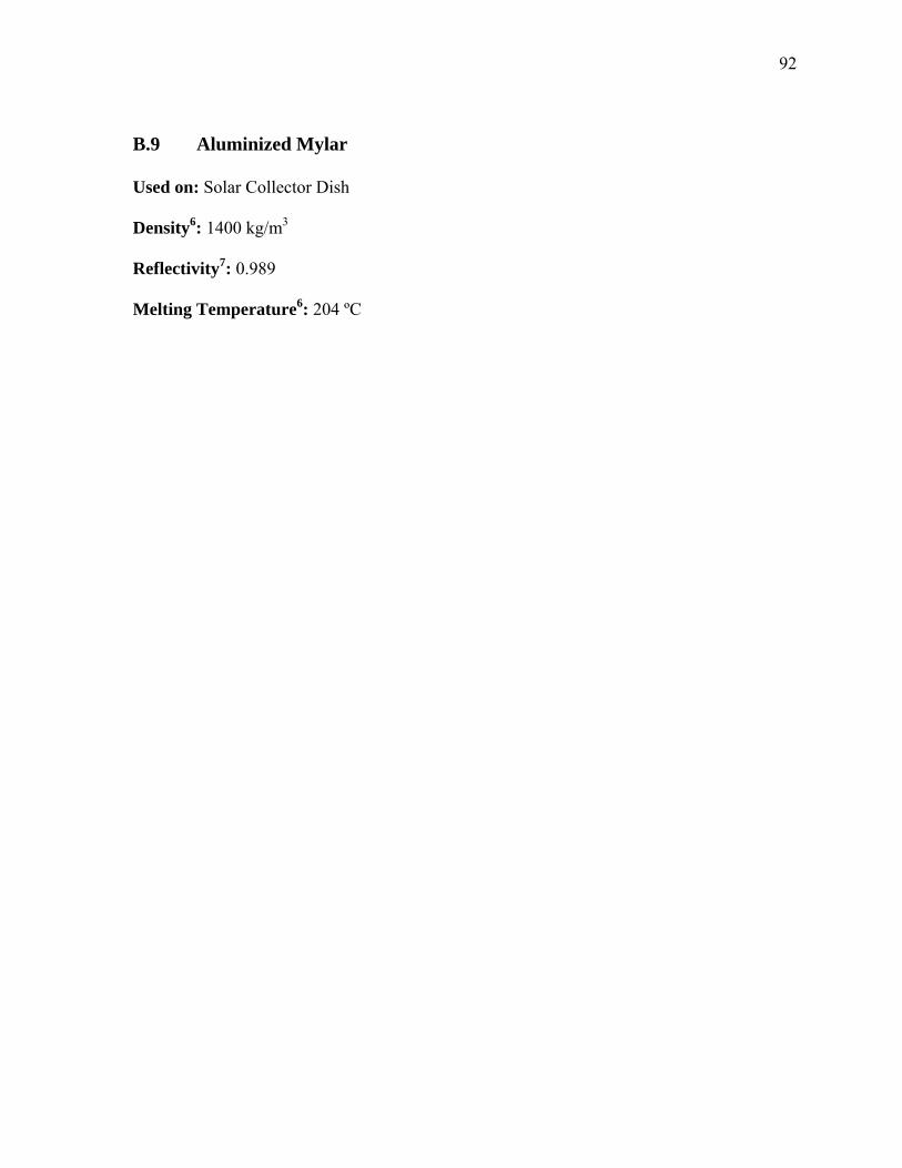
92
B.9 Aluminized Mylar Used on: Solar Collector Dish Density6: 1400 kg/m3 Reflectivity7: 0.989 Melting Temperature6: 204 ºC
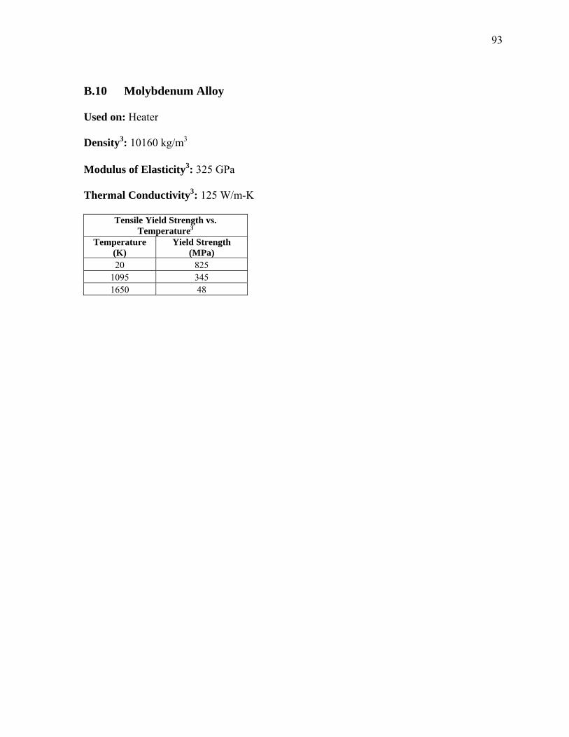
93
B.10 Molybdenum Alloy Used on: Heater Density3: 10160 kg/m3 Modulus of Elasticity3: 325 GPa Thermal Conductivity3: 125 W/m-K
Tensile Yield Strength vs. Temperature3
Temperature (K)
Yield Strength (MPa)
20 825 1095 345 1650 48
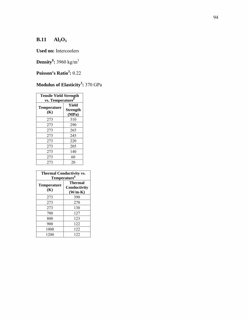
94
B.11 Al2O3 Used on: Intercoolers Density8: 3960 kg/m3 Poisson’s Ratio3: 0.22 Modulus of Elasticity3: 370 GPa
Tensile Yield Strength vs. Temperature8
Temperature (K)
Yield Strength (MPa)
273 310 273 290 273 265 273 245 273 220 273 205 273 140 273 60 273 20
Thermal Conductivity vs.
Temperature8
Temperature (K)
Thermal Conductivity
(W/m-K) 273 390 273 270 273 130 700 127 800 123 900 122
1000 122 1200 122
95
B.12 References
[1] ASM Handbook, Volume 11. (2003). Materials Park, OH : ASM International [2] Boyer, Rodney, Welsch, Gerhard, Collings, E.W. (1994). Materials Properties
Handbook : Titanium Alloys. Materials Park, OH : ASM International. [3] Matweb (2006), Retrieved April 21, 2005, from www.matweb.com [4] Metals and Ceramics Information Center (1974). Handbook on Materials for
Superconducting Machinery. Columbus, OH : Battelle Memorial Institute [5] Kutz, M. (2002). Handbook of Materials Selection. New York, NY : John Wiley
and Sons, Inc. [6] DuPont Teijin Films (2005). Retrieved January 26, 2006 from
www.dupontteijinfilms.com [7] Scott, R. B. (1959). �Cryogenic Engineering.” Toronto Canada, D. Van Nostrand
Company, Inc [8] Prepared under the direction of the ASM International Handbook Committee. (1991).
Engineering Materials Handbook, Vol 4; Ceramics and Glasses. United States : ASM International