Embed Size (px)
Citation preview

FURTHER READINGLITHIUM METAL EXTRACTION FROM SEAWATER.Sixie Yang, Fan Zhang, Huaiping Ding, Ping He and Haoshen Zhou.Joule 2, 1648-1651 Copyright 2018 Elsevier Inc. www.sciencedirect.com/science/article/pii/S2542435118302927 This article by some of the leading scientists in the field estimates that all land based Lithium reserves will be exhausted by 2080. This article further suggests the possible use of solar energy as a power source although not in the way we foresee it nor with the same extraction method.
QUEST TO MINE LITHIUM FROM SEAWATER ADVANCES.Richard MartinMIT Technology review. 2015. www.technologyreview.com/s/538036/quest-to-mine-seawater-for-lithium-advances/ This article discusses the advances made by Tsuyoshi Hoshino and his research into extracting lithium from seawater by dialysis.
INNOVATIVE LITHIUM RECOVERY TECHNIQUE FROM SEAWATER BY USING WORLD- FIRST DIALYSIS WITH A LITHIUM IRON SUPERCONDUCTOR.Tsuyoshi Hoshino.ScienceDirect/Joule Copyright Elsevier B.V. 2019. https://core.ac.uk/download/pdf/82317531.pdf This paper deals with Dr. Hoshino’s research in detail.
MEMBRANES WILL SLASH ENERGY AND HARVEST LITHIUM SAY RESEARCHERS.Copyright Faversham House Group 2018. https://www.desalination.biz/news/0/MOF-membranes-will-slash-energy-use-harvest-lithium-say-researchers/8942/ This article references the work of Australian and American scientists and their work on Metal Organic Frameworks via Monash University.
MINING CRITICAL METALS AND ELEMENTS FROM SEAWATER: OPPORTUNITIES AND CHALLENGES.Dr. Mamadou S.Diallo, Madhusudhana Rao Kotte and Manki Cho.Environmental Chemical Society. Copyright American Chemical Society. 2015. https://pubs.acs.org/doi/full/10.1021/acs.est.5b00463 This article highlights the work of Dr. Diallo of the California Institute of Technology.
EXTRACTION OF LITHIUM WITH FUNCTIONALISED LITHIUM ION-SIEVES.Copyright Elsevier B.V. https://www.researchgate.net/publication/308339816_Extraction_of_lithium_with_functionalized_lithium_ion-sieves This paper related to the extraction of lithium from seawater by the use of ion-sieves.
NEW DESALINATION PROCESS COULD EXTRACT VITAL BATTERY MATERIAL: LITHIUM.Matt Weiser. Water Deeply. 2018. https://www.newsdeeply.com/water/community/2018/06/27/new-desalination-process-could-extract-vital-battery-material-lithium This article is in part an interview with Benny Freeman, Professor of chemical engineering at the University of Texas, discussing the use of MOF’s in the extraction of lithium from seawater and the progress that is being made.
EXTRACTING LITHIUM FROM WATER USING SYNTHETIC MEMBRANES.Amanda Doyle. The Chemical Engineer.Copyright Institution of Chemical Engineers. 2019. https://www.thechemicalengineer.com/27841 This article is about further MOF research and development.
LITHIUM AND COBALT - A TALE OF TWO COMMODITIES.Marcelo Azevedo, Nicolò Campagnol, Toralf Hagenbruch, Ken hoffman, Ajay Lala, Oliver Ramsbottom. Metals and Mining: June 2018https://www.mckinsey.com/industries/metals-and-mining/our-insights/lithium-and-cobalt-a-tale-of-two-commodities
TOSSED ASIDE IN THE WHITE GOLD RUSH.Story by Todd C. Frankel and Peter WhoriskeyPhotos and videos by Michael Robinson ChavezVideo editing by Jorge Ribashttps://www.washingtonpost.com/graphics/business/batteries/tossed-aside-in-the-lithium-rush/
LITHIUM METAL EXTRACTION FROM SEAWATER.Sixie Yang, Fan Zhang, Huaiping Ding, Ping He and Haoshen Zhou.Joule 2, 1648-1651 Copyright 2018 Elsevier Inc. www.sciencedirect.com/science/article/pii/S2542435118302927 This article by some of the leading scientists in the field estimates that all land based Lithium reserves will be exhausted by 2080.This article further suggests the possible use of solar energy as a power source although not in the way we foresee it nor with thesame extraction method.
QUEST TO MINE LITHIUM FROM SEAWATER ADVANCES.Richard MartinMIT Technology review. 2015. www.technologyreview.com/s/538036/quest-to-mine-seawater-for-lithium-advances/ This article discusses the advances made by Tsuyoshi Hoshino and his research into extracting lithium from seawater by dialysis.
INNOVATIVE LITHIUM RECOVERY TECHNIQUE FROM SEAWATER BY USING WORLD- FIRST DIALYSIS WITH A LITHIUM IRON SUPERCONDUCTOR.Tsuyoshi Hoshino.ScienceDirect/Joule Copyright Elsevier B.V. 2019. https://core.ac.uk/download/pdf/82317531.pdf This paper deals with Dr. Hoshino’s research in detail.
MEMBRANES WILL SLASH ENERGY AND HARVEST LITHIUM SAY RESEARCHERS.Copyright Faversham House Group 2018. https://www.desalination.biz/news/0/MOF-membranes-will-slash-energy-use-harvest-lithium-say-researchers/8942/ This article references the work of Australian and American scientists and their work on Metal Organic Frameworks via Monash University.
MINING CRITICAL METALS AND ELEMENTS FROM SEAWATER: OPPORTUNITIES AND CHALLENGES.Dr. Mamadou S.Diallo, Madhusudhana Rao Kotte and Manki Cho.Environmental Chemical Society.Copyright American Chemical Society. 2015. https://pubs.acs.org/doi/full/10.1021/acs.est.5b00463 This article highlights the work of Dr. Diallo of the California Institute of Technology.
EXTRACTION OF LITHIUM WITH FUNCTIONALISED LITHIUM ION-SIEVES.Copyright Elsevier B.V. https://www.researchgate.net/publication/308339816_Extraction_of_lithium_with_functionalized_lithium_ion-sieves This paper related to the extraction of lithium from seawater by the use of ion-sieves.
NEW DESALINATION PROCESS COULD EXTRACT VITAL BATTERY MATERIAL: LITHIUM.Matt Weiser. Water Deeply. 2018. https://www.newsdeeply.com/water/community/2018/06/27/new-desalination-process-could-extract-vital-battery-material-lithium This article is in part an interview with Benny Freeman, Professor of chemical engineering at the University of Texas, discussing the useof MOF’s in the extraction of lithium from seawater and the progress that is being made.
EXTRACTING LITHIUM FROM WATER USING SYNTHETIC MEMBRANES.Amanda Doyle. The Chemical Engineer.Copyright Institution of Chemical Engineers. 2019. https://www.thechemicalengineer.com/27841 This article is about further MOF research and development.
LITHIUM AND COBALT - A TALE OF TWO COMMODITIES.Marcelo Azevedo, Nicolò Campagnol, Toralf Hagenbruch, Ken hoffman, Ajay Lala, Oliver Ramsbottom. Metals and Mining: June 2018https://www.mckinsey.com/industries/metals-and-mining/our-insights/lithium-and-cobalt-a-tale-of-two-commodities
TOSSED ASIDE IN THE WHITE GOLD RUSH.Story by Todd C. Frankel and Peter WhoriskeyPhotos and videos by Michael Robinson ChavezVideo editing by Jorge Ribashttps://www.washingtonpost.com/graphics/business/batteries/tossed-aside-in-the-lithium-rush/

Patent Pending
Field of the invention The present invention relates to a floating filtration system and a method of filtering using a floating filtration system.
Background of the invention Natural resources such as lithium are often extracted via traditional mining methods. For example, resource-bearing hard rock is unearthed and then treated (e.g. via heating, crushing, sifting or a chemical process) to release the desired resource (e.g. lithium). This is an expensive and labour intensive process leaving considerable mining tailings (i.e. waste) and huge environmental impact. For example, the rivers around the Ganzizhou Ronda lithium mine in China have seen a large reduction in the number of fish. This mine was also briefly shut down after yak and oxen were found dead from drinking contaminated water in rivers close to the plant.
Sometimes, resources can be more easily obtained from accumulations of saline groundwater known as “brine deposits”. For example, lithium brine deposits (such as those in the “Lithium Triangle” of South America) are accumulations of saline groundwater with a relatively high dissolved lithium content. To extract the lithium from these deposits, groundwater is pumped from underground aquifers to the surface, where it sits in a series of pools for 12 to 18 months until natural evaporation leaves behind a residue of lithium rich salt. Since this is a slow process, there is no option to ramp up production quickly to meet an increased demand.
Furthermore, it takes around 2 million litres of water to produce a tonne of lithium from brine deposits, which has negative impacts on the environment and local water supply. For example, in the “Lithium Triangle” of South America, such lithium extraction operations consume around 65% of the local water supply, leading to water shortages for domestic and agricultural use.
Many resources are present in large quantities in seawater (even if only present at relatively low concentrations). For example, the total lithium content of seawater is estimated as 230 billion tonnes. There are a number of techniques for extracting lithium or other resources from seawater (e.g. metal-organic frameworks, dialysis or ion-sieves), and this is an active research area with many new filter developments envisaged over the next few years. However, since the lithium concentration in seawater is relatively low, it may not be commercially-viable to use seawater filtering techniques to extract lithium (e.g. due to the need to continually pump seawater to filtration plants).
The present invention seeks to overcome, or at least mitigate, one or more problems of the prior art.

Summary of the invention
Summary of the invention To be inserted after claims/advantages finalised.
Brief description of the drawings
Figure 1 is a schematic diagram of a filtration system according to an embodiment; Figure 2 is a schematic diagram of a filtration system having solar panels, according to an embodiment; Figure 3 is a schematic diagram of a solar tracking system and a solar panel cooling system for the filtration system of Figure 2; Figure 4 is a schematic diagram of a filtration system having wind turbines, according to an embodiment; Figure 5 is a schematic diagram of a filtration module interchangeably coupled to a floatation body of the filtration system of any of Figures 1, 2 or 4; and Figure 6 is a schematic diagram of a modular floatation body for the filtration system of any of Figures 1, 2 or 4.
Detailed description
Referring to Figure 1, a filtration system according to an embodiment is indicated at 10. The filtration system 10 includes a floatation body 12 configured to float on water 14 and a plurality of filtration modules 16 configured to isolate metal ions present in water. Having a plurality of filtration modules 16 increases the capacity of metal ions that can be isolated from the water 14. Furthermore, a plurality of smaller filtration modules 16 may be more robust than a single large filtration module 16 of similar capacity, since if an individual filtration module 16 becomes damaged, the other filtration modules 16 are unaffected.
In alternative embodiments, a single filtration module 16 may be provided rather than a plurality of filtration modules 16.
The filtration system 10 also includes a filtration pump 18 configured to convey water to the filtration module 16, and a power system 20 configured to power the filtration pump 18. In alternative embodiments, more than one filtration pump 18 may be provided (e.g. a dedicated filtration pump 18 for each filtration module 16).
In the illustrated embodiment, the filtration system 10 is a seawater filtration system (i.e. the body of water 14 is a body of seawater). It is known that seawater contains vast sources of metal ions. For example, there are around 230 billion tonnes of lithium in seawater at 0.14 to 0.25 parts per million. Therefore, the filtration system 10 being a seawater filtration system makes it suitable for isolating such ions. Furthermore, lithium has a multitude of industrial uses (e.g. lithium ion batteries and medications) and therefore its isolation from seawater provides a means of harvesting this natural resource for such uses.
In alternative embodiments, the filtration system 10 may be provided on an alternative body of water 14 rather than seawater (e.g. brines, waste water from desalination plants, waste water from geothermal power plants, waste water from other industrial plants etc.).
In the illustrated embodiment, the filtration modules 16, filtration pump 18 and power system 20 are provided on the floatation body 12. In alternative embodiments, one or more of these elements may be coupled for movement with the floatation body 12 by other means (e.g. spaced apart from but tethered to the floatation body 12).

By providing the filtration modules 16 and filtration pump 18 coupled to the floatation body 12 for movement with the floatation body 12, it is possible to isolate metal ions from the body of water 14 on which the floatation body 12 is disposed, without having to pump water to an onshore apparatus for filtering. This minimises the distance the water needs to be pumped, which results in a reduced energy demand of the filtration pump 18, over land-based systems.
Furthermore, having the power system 20 coupled to the floatation body 12 for movement with the floatation body 12 means that the filtration system 10 can be provided at any location on a body of water 14, without having to be located close to the shore for receiving a power cable.
Providing the filtration modules 16, the filtration pump 18 and the power system 20 on the floatation body 12 allows these elements of the filtration system to be accessed more easily (e.g. via a maintenance operator climbing onto the floatation body 12) than if they were coupled to the floatation body 12 otherwise (e.g. separate to the body 12 and coupled to the body via cables, pipes etc.). In addition, this provides a compact arrangement which is less likely to get caught on aquatic plants or animals.
The filtration system 10 has an inlet 22 for collecting water to be conveyed to the filtration module 16. The inlet 22 is arranged for receiving water from a depth D below the floatation body 12. Locating the inlet 22 such that water is received from a depth below the floatation body 12 (i.e. from below the surface 24 of the water 14 on which the floatation body 12 floats) ensures that any debris floating at or near the surface 24 of the water 14 is avoided and is not conveyed by the filtration pump 18 to the filtration modules 16. This reduces the chance of blockages in the filtration system 10, which could lead to equipment damage or increased maintenance requirements (e.g. clearing the blockages).
The inlet 22 includes a pipe 26 in fluid communication with the filtration modules 16. The pipe 26 is configured to extend to a depth D below the surface 24 of the water 14 in use.
In the illustrated embodiment, the depth D is around 10m below the surface 24 of the water 14. In alternative embodiments, the depth D may be any distance in the range 0.5m to 20m, or 5m to 15m below the surface 24 of the water 14. The pipe 26 extending to such a depth D has been found to be deep enough to avoid the majority of debris floating at or near the surface 24 of the water 14, without making the pipe 26 too long so as to increase the energy required to pump water from the inlet 22 to the filtration modules 16.
The pipe 26 has a free end 28 and the filtration system 10 includes a strainer 30 in association with the free end 28. The strainer 30 is arranged and configured for preventing the transfer of undesired debris along the pipe 26. In the illustrated embodiment, this is achieved via positioning the strainer 30 around the free end 28 of the pipe 26. In alternative embodiments, a filter for preventing transfer of undesired debris along the pipe may be provided in association with the free end 28, instead of a strainer 30. For example, a filter may be positioned within the pipe 26 close to the free end 28. Having a strainer 30 or filter reduces the likelihood of debris passing into the filtration system 10, which protects equipment from damage and reduces maintenance requirements (i.e. by preventing the need to clear out blockages).
As will be described in more detail below in relation to Figure 5, each filtration module 16 is interchangeably coupled to the floatation body 12, such that the filtration module 16 can be replaced by a filtration module 16 of similar or different filter type. By having an interchangeable filtration module 16, the filtration system 10 is capable of being upgraded to use whatever filtration technique is technologically most advanced and/or cheapest and/or most readily available etc. This can be done simply by replacing the filtration module 16, rather than upgrading the entire filtration system 10. This is particularly useful for the illustrated filtration system 10 which is configured to isolate lithium ions from seawater, since rapid technological advancements in this area are leading to huge improvements in such filtering techniques.

By having interchangeable filtration modules 16, the filtration modules 16 may be replaced by alternative filtration modules 16 configured to isolate a different type of metal ion. This could be beneficial if the price of lithium falls but the price of another ion present in seawater or other bodies of water rises, for example. Another configuration would allow different filtration modules 16 to be used at the same time, to isolate more than one type of ion from the water 14.
The filtration pump 18 has a pump inlet 32 and a pump outlet 34. The pipe 26 of the inlet 22 is connected to the pump inlet 32, and the pump outlet 34 is connected to a filter conduit 36. A filter outlet 38 is provided for conveying water from the filtration module 16 to the body of water 14. As will be described in more detail below in relation to Figure 4, the filter conduit 36 and filter outlet are selectively connectable to the filtration modules 16 in order to install or remove the filtration module 16 from the filtration system 10. By having a filter conduit 36 which is selectively connectable to the filtration modules 16, rather than fixedly connected (e.g. via welding), the filtration modules 16 can be disconnected from the filter conduit 36 and replaced by filtration modules 16 of alternate filter type but similar geometrical construction (i.e. having a similar shape for connection to the filter conduit 36).
The power system 20 includes a renewable power generation apparatus 40. Having a renewable power generation apparatus 40 removes the need for refuelling or replacing components over other power generation systems (e.g. a diesel generator). Accordingly, having a renewable power generation apparatus 40 allows the filtration system 10 to operate over a longer period of time, or even indefinitely. Furthermore, renewable power generation apparatuses 40 do not generate greenhouse gases in use, which reduces the environmental impact of the filtration system 10 over those with other power generation apparatuses (e.g. a diesel generator).
As will be described in more detail below in relation to Figures 2 to 4, the renewable power generation apparatus 40 may include one or more solar panels 154 and/or wind turbines 266. In alternative embodiments, the renewable power generation apparatus 40 may be a wave energy recovery device. A wave energy recovery device is a reliable source of renewable power, which generates at least some power whenever there is sufficient waves. Many areas of seawater experience consistent wave activity for most or all of the year. In such areas, wave energy recovery devices may be advantageous over solar panels 154, which only generate power during daylight hours, or wind turbines 266, which only generate power when the wind is blowing.
In some embodiments, the wave energy recovery device may include a kinetic energy recovery mechanism configured to convert kinetic energy of the floatation body 12 into rotation of an electrical generator shaft. Such a kinetic energy recovery mechanism uses some of the substantial amount of kinetic energy of a floatation body 12 in wavy water to generate power for the filtration system 10. In other embodiments, the wave energy recovery device may include a piezoelectric device. Piezoelectric devices generate electrical charge in response to mechanical stress, without any moving parts. Therefore, they may offer a low-maintenance option for generating renewable power.
In the illustrated embodiment, the renewable power generation apparatus 40 is provided on the floatation body 12. In alternative embodiments, the renewable power generation apparatus 40 may be separate from the floatation body 12 (e.g. a wave energy recovery buoy coupled to the floatation body 12).
The power system 20 also includes an energy storage device 42. An energy storage device 42 provides a reliable means of supplying power regardless of environmental conditions (e.g. as opposed to solar panels 154 which only generate power during the day). The energy storage device 42 of the illustrated embodiment includes one or more batteries. Batteries have been known to provide an efficient and reusable means of storing electrical energy. In addition, suitable batteries are widely available as off-the-shelf components.
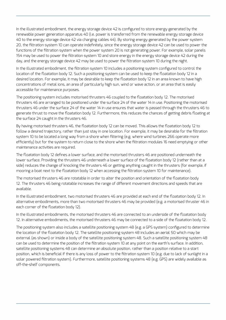
In the illustrated embodiment, the energy storage device 42 is configured to store energy generated by the renewable power generation apparatus 40 (i.e. power is transferred from the renewable energy storage device 40 to the energy storage device 42 via charging cables 44). By storing energy generated by the power system 20, the filtration system 10 can operate indefinitely, since the energy storage device 42 can be used to power the functions of the filtration system when the power system 20 is not generating power. For example, solar panels 154 may be used to power the filtration system 10 and store energy in the energy storage device 42 during the day, and the energy storage device 42 may be used to power the filtration system 10 during the night.
In the illustrated embodiment, the filtration system 10 includes a positioning system configured to control the location of the floatation body 12. Such a positioning system can be used to keep the floatation body 12 in a desired location. For example, it may be desirable to keep the floatation body 12 in an area known to have high concentrations of metal ions, an area of particularly high sun, wind or wave action, or an area that is easily accessible for maintenance purposes.
The positioning system includes motorised thrusters 46 coupled to the floatation body 12. The motorised thrusters 46 are arranged to be positioned under the surface 24 of the water 14 in use. Positioning the motorised thrusters 46 under the surface 24 of the water 14 in use ensures that water is passed through the thrusters 46 to generate thrust to move the floatation body 12. Furthermore, this reduces the chances of getting debris floating at the surface 24 caught in the thrusters 46.
By having motorised thrusters 46, the floatation body 12 can be moved. This allows the floatation body 12 to follow a desired trajectory, rather than just stay in one location. For example, it may be desirable for the filtration system 10 to be located a long way from a shore when filtering (e.g. where wind turbines 266 operate more efficiently) but for the system to return close to the shore when the filtration modules 16 need emptying or other maintenance activities are required.
The floatation body 12 defines a lower surface, and the motorised thrusters 46 are positioned underneath the lower surface. Providing the thrusters 46 underneath a lower surface of the floatation body 12 (rather than at a side) reduces the change of knocking the thrusters 46 or getting anything caught in the thrusters (for example, if mooring a boat next to the floatation body 12 when accessing the filtration system 10 for maintenance).
The motorised thrusters 46 are rotatable in order to alter the position and orientation of the floatation body 12. The thrusters 46 being rotatable increases the range of different movement directions and speeds that are available.
In the illustrated embodiment, two motorised thrusters 46 are provided at each end of the floatation body 12. In alternative embodiments, more than two motorised thrusters 46 may be provided (e.g. a motorised thruster 46 in each corner of the floatation body 12).
In the illustrated embodiments, the motorised thrusters 46 are connected to an underside of the floatation body 12. In alternative embodiments, the motorised thrusters 46 may be connected to a side of the floatation body 12.
The positioning system also includes a satellite positioning system 48 (e.g. a GPS system) configured to determine the location of the floatation body 12. The satellite positioning system 48 includes an aerial 50 which may be external (as shown) or inside a body of the satellite positioning system 48. Such a satellite positioning system 48 can be used to determine the position of the filtration system 10 at any point on the earth’s surface. In addition, satellite positioning systems 48 can determine an absolute position, rather than a position relative to a start position, which is beneficial if there is any loss of power to the filtration system 10 (e.g. due to lack of sunlight in a solar powered filtration system). Furthermore, satellite positioning systems 48 (e.g. GPS) are widely available as off-the-shelf components.

The positioning system is configured to maintain the location of the floatation body 12 (e.g. as determined by the satellite positioning system 48) at a desired location via actuation of the motorised thrusters 46.
The filtration system 10 also includes a positioning mechanism in the form of an anchor 52 configured to tether the floatation body 12 to the seabed, or bed of another type of water body (e.g. lake bed). Such an anchor 52 provides a means for maintaining the position of the floatation body 12 at a desired location indefinitely, without a need for power (unlike the positioning system described above). However, the anchor 52 is not able to facilitate movement of the floatation body 12 to a new desired location. Therefore, the filtration system 10 may use the positioning system including the motorised thrusters 46 and satellite positioning system 48 to move the floatation body 12 to a desired location, then use the anchor 52 to maintain the position of the floatation body 12. However, the motorised thrusters 46 may still be used to alter the orientation of the floatation body 12 (e.g. to maximise solar power generation, as described below in relation to Figures 2 and 3).
In alternative embodiments, the positioning mechanism may include a rope or the like configured to connect the floatation body 12 to shore or to an offshore structure (e.g. oil rig), instead of or in addition to having a bed anchor 52. Having a tether connected to shore or an offshore structure ensures that the floatation body 12 can be easily accessed for maintenance activities. For example, the tether could be a winch configured to pull the floatation body 12 close to shore or an offshore structure when a filtration module 16 needs emptying.
In alternative embodiments, the filtration system 10 may only include the positioning system having motorised thrusters 46 and satellite positioning system 48. In alternative embodiments, the filtration system 10 may only include a positioning mechanism in the form of a bed anchor 52 (i.e. without the motorised thrusters 46 and satellite positioning system 48). In alternative embodiments, the filtration system 10 may only have a positioning mechanism in the form of a tether to shore or to an offshore structure (i.e. i.e. without the motorised thrusters 46, satellite positioning system 48 or bed anchor 52). In alternative embodiments, any combination of the positioning system or positioning mechanism described above may be used.
Referring now to Figure 2, a filtration system according to an embodiment is indicated at 110. Corresponding components between the filtration systems of Figures 2 and 1 are labelled with the prefix “1”, and only differences are discussed.
The power system 120 of the filtration system 110 includes a plurality of solar panels 154. Solar panels 154 are a reliable source of renewable power, which generate at least some power whenever it is light. Furthermore, the cost of solar panels 154 has decreased significantly over recent years so that they offer one of the cheapest sources of renewable power. Having a plurality of solar panels 154 offers an increased power generation capability over a single solar panel. However, in alternative embodiments, only a single solar panel 154 may be provided (e.g. if this provides sufficient power generation capability to meet the requirements of the filtration system 110).
Referring now to Figure 3, the filtration system 110 also includes a solar panel cooling system configured to convey water to the solar panels 154. In this figure, only one solar panel 154 is depicted, but the skilled person would understand that the solar panel cooling system could convey water to all of the solar panels 154 of the filtration system 110. Solar panels 154 have been found to operate 16% more efficiently when cooled. Since the filtration system 110 floats on a body of water 14, there is a large heat sink of cool water (in comparison to the surface of a solar panel 154 which can reach high temperatures due to absorbing energy from the sun). Therefore, by conveying water to the solar panels 154, heat can easily be transferred away from the solar panels 154 to the water 14.

In the illustrated embodiment, the solar panel cooling system includes an independent cooling pump 156 configured to convey water to the solar panel 154 via cooling pipe 158. By providing the cooling pump 156 independently of the main filtration pump 118, the cooling pumps 156 can be sized to be optimal for the cooling function. In addition, the cooling pumps 156 can be turned off (e.g. if the solar panels 154 are already at optimal temperature) whilst the filtration pump 118 continues to operate. Furthermore, this removes any need for a valve arrangement to split the flow of water provided from the filtration pump 118 between the filtration modules 116 and solar panel cooling system.
A single independent cooling pump 156 may be configured to convey water to all of the solar panels 154 via cooling pipes 158 (e.g. in series, with cooling pipe 158 of Figure 3, running past the solar panels 154 one after the other, or in parallel, with multiple cooling pipes 158 branching off from the independent cooling pump 156). In alternative embodiments, an independent cooling pump 156 may be provided for each solar panel 154. In alternative embodiments, a first plurality of independent cooling pumps 156 may be provided to convey water to a second plurality of solar panels 154, with the second plurality being greater than the first (e.g. 10 solar panels 154 may be served by 2 independent cooling pumps 156, with each cooling pump 156 conveying water to 5 solar panels 154).
In alternative embodiments, the solar panel cooling system is configured to convey water provided by the filtration pump 118 to the solar panels via cooling pipes 158 (i.e. instead of via one or more independent cooling pumps 156). By using water from the filtration pump 118 in the cooling system, there is no need to provide additional cooling pumps 156, which may result in a cheaper pump arrangement.
Referring now to Figures 2 and 3, the filtration system 110 also includes a solar tracking system configured to orientate the solar panels 154 to face the sun in order to optimise power generation. Facing the sun increases the amount of sunlight that falls on the solar panels 154, which means that the solar panel 154 generate more power when facing the sun than when facing away from the sun. Therefore, such a solar tracking system increases the amount of power generated by the solar panels 154.
In the embodiment illustrated in Figure 3, the solar tracking system includes adjustment motors 162, 164 configured to alter the position of the solar panels 154, as will be described in more detail below. There are a wide variety of low cost and low power motors that could be used alter the position of the solar panels 154. Therefore, having one or more adjustment motors 162, 164 provides a simple and energy-efficient mechanism for orientating the solar panels 154.
In the illustrated embodiment, the floatation body 12 defines a substantially planar surface 160, which provides a simple arrangement receiving the solar panels 154 and adjustment motor 162.
Each solar panel 154 includes a yaw adjustment motor 162 configured to rotate the solar panel 154 about an axis perpendicular to the planar surface 160. Having a yaw adjustment motor 162 allows the solar panels 154 to be rotated in order to face the sun. For example, the yaw adjustment motor 162 may rotate the solar panel 154 from east to west throughout the day. This leads to increased power generation.
Each solar panel also includes a pitch adjustment motor 164 configured to rotate the solar panel 154 about an axis parallel to the planar surface 160. Having a pitch adjustment motor 164 allows the pitch of the solar panels 154 to be altered in order to face the sun. For example, the pitch adjustment motor 164 may set the solar panel 154 to be relatively horizontal (e.g. as shown in Figure 3) when the sun is high in the sky during the middle of the day, and relatively steeply inclined (e.g. as shown in Figure 2) when the sun is low in the sky early or late in the day. This leads to increased power generation.
In alternative embodiments, only one of the yaw adjustment motor 162 or the pitch adjustment motor 164 may be provided to orientate the solar panels 154.

In some embodiments, the solar tracking system includes two or more rotatable motorised thrusters 146 coupled to the floatation body 112, as described above in relation to Figure 1. Having two or more motorised thrusters 146 coupled to the floatation body 112 allows the floatation body 112 and any solar panels 154 provided thereon to be moved in order to change their orientation. When orientated to face the sun, this increases power generation of the solar panel(s).
In some embodiments, the motorised thrusters 146 may be provided instead of the yaw adjustment motor 162 to rotate the floatation body 112 and the solar panel 154 thereon about an axis perpendicular to the planar surface 160.
In alternative embodiments, both yaw and pitch adjustment motors 162, 164 may be provided, and the motorised thrusters 146 may be used to move the floatation body 112 to a different location to optimise power generation. For example, the motorised thrusters 146 may move the floatation body 112 away from an area of the water 114 as it becomes shaded at a particular time of the day.
Referring now to Figure 4, a filtration system according to an embodiment is indicated at 210. Corresponding components between the filtration systems of Figures 3 and 1 are labelled with the prefix “2”, and only differences are discussed.
The power system 220 of the filtration system 210 includes a plurality of wind turbines 266. Wind turbines 266 are a reliable source of renewable power, which generate at least some power whenever there is sufficient wind. In windy areas, this may be advantageous over solar panels 154 which only generate power during daylight hours. Furthermore, wind turbines 266 offer one of the cheapest sources of renewable power.
Having a plurality of wind turbines 266 offers an increased power generation capability over a single wind turbine 266. However, in some embodiments, only a single wind turbine 266 may be provided (e.g. where the power generated by a single wind turbine 266 is sufficient to power the filtration system 210).
The filtration system 210 includes a wind tracking system configured to orientate the wind turbines 266 to face the direction of the wind, in order to optimise power generation. Facing the wind increases the amount of air flow over the blades of a wind turbine, which means that the wind turbines 266 generate more power when facing the wind than when facing away from the wind. Therefore, such a wind tracking system increases the amount of power generated by the wind turbines 266.
As will be described in more detail below, the wind tracking system includes one or more adjustment motors 262 configured to alter the orientation of the wind turbines 266. There are a wide variety of low cost and low power motors that could be used alter the position of the wind turbines 266. Therefore, having one or more adjustment motors 262 provides a simple and energy-efficient mechanism for orientating the wind turbines.
In the illustrated embodiment, each wind turbine 266 includes a yaw adjustment motor 262 configured to rotate the wind turbine 266 about an axis perpendicular to the planar surface 260 of the floatation body 212. Having a yaw adjustment motor 262 allows a wind turbine 262 to be rotated in order to face the wind. This leads to increased power generation.
In some embodiments, the wind tracking system includes two or more motorised thrusters 246 coupled to the floatation body 212, as described above in relation to Figure 1. Having two or more motorised thrusters 246 coupled to the floatation body 212 allows the floatation body 212 and any wind turbines 262 provided thereon to be moved in order to change their orientation. When orientated to face the wind, this increases power generation of the wind turbines.

In some embodiments, both the yaw adjustment motors 262 and motorised thrusters 246 may be used to alter the orientation of the wind turbines 262. In alternative embodiments, the wind tracking system may include only yaw adjustment motors 262 or only motorised thrusters 246. In some embodiments, the wind tracking system may use the motorised thrusters 246 to move the floatation body 212 to a new position on the body of water 14 with higher wind activity (e.g. based on weather forecasts), whereas the yaw adjustment motors 262 may be used to orientate the wind turbines 262 to face the wind at a given location.
Referring now to Figure 5, the filtration module 16 is provided on the floatation body 12. The filtration module 16 includes a first releasable engagement formation in the form of a flange 68. The floatation body 12 includes a second releasable engagement formation in the form of a shoulder 70 for engagement with the flange 68. Both the flange 68 and the shoulder 70 include bolt holes for receiving a bolt 72 therethrough, in order to secure the filtration module 16 to the floatation body 12.
In alternative embodiments, any other form of releasable engagement formation may be used. For example, the bolt holes and bolt 72 may be omitted, and the filtration module 16 may be held in place via the flange 68 resting on the shoulder 70; or the flange 68 and shoulder 70 may be omitted, and the filtration module 16 may just rest within a receiving recess of the floatation body 12.
In the illustrated embodiment, the filtration module is provided at an upper surface of the floatation body 12. In alternative embodiments, the filtration module 16 may be provided at a depth within the floatation body 12.
By having first and second releasable engagement formations 68, 70, the filtration module 16 can be removed or replaced more easily than if the filtration module 16 was integral to the floatation body or coupled to the floatation body via a non-releasable engagement such as a welded joint.
In the illustrated embodiment, the filter conduit 36 is selectively connectable to the filtration module 16 in order to install or remove the filtration module 16 from the filtration system 10. Similarly, the filter outlet 38 is selectively connectable to the filtration module 16 in order to install or remove the filtration module 16 from the filtration system 10. The filtration module 16 includes a filtration module inlet 74 for connection to the filter conduit 36. The filtration module inlet 74 may include a sealing arrangement to prevent water from the filter conduit 36 leaking and bypassing the filtration module 16.
The filtration module 16 also includes a filtration module outlet 76 for connection to the filter outlet 38. The filtration module outlet 76 may include a sealing arrangement to prevent water from the filtration module 16 leaking and bypassing the filter outlet 38. The filtration module outlet 76 may be configured for one way flow out of the filtration module 16 (e.g. via a check valve) so that no backflow of filtered water from the filter outlet 38 to the filtration module 16 is permitted.
An end of the filter conduit 36 proximal the filtration module 16 may include a valve or other flow control device configured to prevent water leaving the filter conduit 36 when no filtration module 16 is present. Alternatively, the filter conduit 36 may be open so that if a filtration module 16 is missing, water flows via the receiving recess intended to house the filtration module 16 to the filter outlet 38. In the illustrated embodiment, this would be possible since the filter outlet 38 is positioned lower than the filter conduit 36.

Only an example filtration module arrangement is depicted in Figure 4. However, the skilled person would understand that any suitable arrangement or means of connecting the filtration module 16 to the filter conduit 36 could be provided. For example, rather than having a filter outlet 38, the floatation body 12 may be open to the body of water 14 proximal a lower end of the filtration module 16, and the filtration module outlet 76 may be located at the bottom of the filtration module so that water can be flushed from the filtration module 16 to the body of water 14 via gravity.
In the illustrated embodiment, the filtration module 16 includes a metal organic framework 78 configured to separate lithium ions from said water 14. Metal organic frameworks 78 can easily be configured to isolate a specific element (e.g. lithium). Furthermore, metal organic frameworks 78 do not require an input of energy to perform such isolation, unlike other methods such as electrolysis.
In alternative embodiments, the metal organic framework 78 may be configured to isolate different elements from the water 14. In alternative embodiments, the filtration module 16 may include a filter or other separation means different to a metal organic framework 78.
The filtration system 10 includes a sensor 80 configured to measure data indicative of the quantity of metal ions present in the filtration module 16. Such a sensor 80 is able to give an indication of when the filtration module 16 needs emptying. This provides a more reliable means of determining the state of the filtration module 16 than manual inspection.
In the illustrated embodiment, the sensor 80 is part of the filtration module 16. In alternative embodiments, the sensor 80 may be located on the floatation body 12 separate from the filtration module 16.
The filtration system also includes a processor 82 configured to process said data indicative of the quantity of metal ions present in the filtration module 16 to provide an alert or processed ion quantity data. By having a processor 82, the raw data from the sensor 80 can be processed into a form that is useful for a supervisor of the filtration system 10.
The filtration system 10 also includes a data sending device 84 configured to send said data indicative of the quantity of metal ions present in the filtration module 16, and/or alert and/or processed ion quantity data to a data receiving device remote from the floatation platform 12. By having a data sending device 84, a supervisor of the filtration system can receive an alert or ion quantity data from the filtration system 10, so that they can plan a maintenance activity to empty the filtration modules 16. This provides a more efficient solution to ensuring the filtration modules 16 are emptied than relying on a supervisor to visit the floatation platform 12 and manually inspect the filtration modules 16.
In the illustrated embodiment, the data sending device 84 is a wireless transmitter configured to send data to a wireless receiver remote from the floatation body 12. By having a wireless transmitter/receiver, the data sending device 84 can send alerts and/or ion quantity data over long distances to a supervisor of the filtration system 10.
In the illustrated embodiment, the processor 82 is configured to determine whether the quantity of metal ions present in the filtration module 16 is above a threshold value, and to provide an alert if the quantity of metal ions is above said threshold value. By alerting the supervisor if the quantity of metal ions is above said threshold value, the filtration system 10 does not need to send data to a supervisor of the system at times when the quantity of metal ions is below the threshold value. This reduces the energy demands of the alerting system.
Referring now to Figure 6, the floatation body 12 is of modular construction. The floatation body 12 includes a plurality of floatation modules 86 configured for engagement with one or more adjacent floatation modules 86.

Having a modular construction allows the size of the floatation body 12 to be varied depending on the requirements of a particular filtration system 10 (e.g. how many filtration modules 16, or how much lithium capture capacity is required). Having a plurality of floatation modules 86 configured for engagement with one another provides a simple means of changing the size and or shape of the floatation body 12.
The floatation body 12 is of glass reinforced plastic construction. Glass reinforced plastic is known to be lightweight, durable and cheap, which makes it suitable for the floatation body 12 of the filtration system 10. In alternative embodiments, the floatation body is made of any other suitable material (e.g. wood, plastic or metal material).
The floatation body 12 includes bulkheads 88 which separate the floatation body 12 into a number of compartments. This means that if a hole develops in one compartment, the other compartments remain unaffected, which prevents the floatation body 12 from filling with water and sinking. In the illustrated embodiment, the bulkheads 88 are provided via the side walls of the floatation modules 86. However, in alternative embodiments, where the floatation body 12 is not of modular construction, bulkheads 88 may be provided as internal walls of the floatation body 12.
Although the invention has been described in relation to one or more embodiments, it will be appreciated that various changes or modifications can be made without departing from the scope of the invention as defined in the appended claims. For example:
the power system 20 may be used to provide power to any of the powered components of the filtration system 10 and not just the filtration pump 18 (e.g. motorised thrusters 46, satellite positioning system 48, cooling pumps 156, adjustment motors 162, 164, sensor 80, processor 82 and data sending device 84);
the power system 20 may include only an energy storage device 42 (e.g. battery) which is replaceable when depleted (i.e. renewable power generation apparatus 40 may be omitted);
any type of renewable power generation apparatus 40 may be provided (e.g. solar panels 154, wind turbines 266, wave energy recovery devices, another type of power generation apparatus, or a combination thereof);
any number of filtration modules 16, filtration pumps 18, motorised thrusters 46, anchors 52 or other tethers, solar panels 154, cooling pumps 156, adjustment motors 162, 164, 262, wind turbines 266 or sensors 80 may be provided;
any suitable means for interchangeably coupling the filtration modules 16 to the floatation body 12 may be used (i.e. not just the specific arrangement outlined in Figure 5); and
any suitable means for engaging adjacent floatation modules 86 may be provided (e.g. clips, bolts or the like).

Claims
1. A filtration system comprising: a floatation body configured to float on water; a filtration module coupled for movement with the flotation body, wherein the filtration module is configured to isolate metal ions present in seawater; a filtration pump coupled for movement with the flotation body and configured to convey water to the filtration module; and a power system coupled for movement with the flotation body and configured to power the filtration pump; wherein the filtration system includes an inlet for collecting water to be conveyed to the filtration module, wherein the inlet is arranged for receiving water from a depth below the floatation body.
According to a first aspect of the invention a filtration system is provided, the filtration system comprising
a floatation body configured to float on water;
a filtration module coupled for movement with the flotation body, wherein the filtration module is configured to isolate metal ions present in water;
a filtration pump coupled for movement with the floatation body, and configured to convey water to the filtration module; and
a power system coupled for movement with the floatation body and configured to power the filtration pump.
By providing a filtration module and a filtration pump both coupled to a floatation body for movement with the floatation body, it is possible to isolate metal ions from a body of water on which the floatation body is disposed, without having to pump water to an onshore apparatus for filtering. This minimises the distance the water needs to be pumped, which results in a reduced energy demand of the pump, over land-based systems.
Furthermore, having a power system coupled to a floatation body for movement with the floatation body means that the filtration system can be provided at any location on a body of water, without having to be located close to the shore for receiving a power cable.
In exemplary embodiments, the filtration system further comprises an inlet for collecting water to be conveyed to the filtration module, optionally wherein the inlet is arranged for receiving water from a depth below the floatation body.
Locating the inlet such that water is received from a depth below the floatation body (i.e. from below the surface of the water on which the floatation body floats) ensures that any debris floating at or near the surface of the water is avoided and is not conveyed by the pump to the filtration module. This reduces the chance of blockages in the filtration system, which could lead to equipment damage or increased maintenance requirements (e.g. clearing the blockages).
In exemplary embodiments, the filtration system is a seawater filtration system and the filtration pump is configured to convey seawater to the filtration module.

It is known that seawater contains vast sources of metal ions. For example, there are around 230 billion tonnes of lithium in seawater at 0.14 to 0.25 parts per million. Therefore, the filtration system being a seawater filtration system makes it suitable for isolating such ions. Furthermore, lithium has a multitude of industrial uses (e.g. lithium ion batteries and medications) and therefore its isolation from seawater provides a means of harvesting this natural resource for such uses.
In exemplary embodiments, the filtration system is a waste water filtration system (e.g. for floating on and filtering waste water from desalination plants, geothermal power plants, or other plants), and the filtration pump is configured to convey waste water to the filtration module.
In exemplary embodiments, the filtration system is a brine filtration system (e.g. for floating on and filtering brines), and the filtration pump is configured to convey brine to the filtration module.
In exemplary embodiments, the filtration module is provided on the floatation body.
In exemplary embodiments, the filtration pump is provided on the floatation body.
In exemplary embodiments, the power system is provided on the floatation body.
Providing the filtration module and/or the filtration pump and/or the power system on the floatation body allows these elements of the filtration system to be accessed more easily (e.g. via a maintenance operator climbing onto the floatation body) than if they were coupled to the floatation body otherwise (e.g. separate to the body and coupled to the body via cables, pipes etc). In addition, this provides a compact arrangement which is less likely to get caught on aquatic plants or animals. 2. A filtration system according to claim 1, wherein the inlet comprises a pipe in fluid communication with the filtration module, wherein the pipe is configured to extend to a depth in the range of 8m to 12m below the surface of the water in use.
In exemplary embodiments, the inlet comprises a pipe in fluid communication with the filtration module, wherein the pipe is configured to extend to a depth in the range of 0.5m to 20m below the surface of the water in use.
In exemplary embodiments, the pipe is configured to extend to a depth in the range of 5m to 15m below the surface of the water in use.
In exemplary embodiments, the pipe is configured to extend to a depth of substantially 10m below the surface of the water in use.
A pipe extending to such a depth has been found to be deep enough to avoid the majority of debris floating at or near the surface of the water, without making the pipe too long so as to increase the energy required to pump water from the inlet to the filtration module.
In exemplary embodiments, the pipe comprises a free end and the filtration system further comprises a strainer or filter in association with the free end, wherein the strainer or filter is arranged and configured for preventing the transfer of undesired debris along the pipe.
Such a strainer or filter reduces the likelihood of debris passing into the filtration system, which protects equipment from damage and reduces maintenance requirements (i.e. by preventing the need to clear out blockages).

3. A filtration system according to claim 1 or 2, wherein the filtration module is interchangeably coupled to the floatation body, such that the filtration module can be replaced by a filtration module of similar or different filter type.
By having an interchangeable filtration module, the filtration system is capable of being upgraded to use whatever filtration technique is technologically most advanced and/or cheapest and/or most readily available etc. This can be done simply by replacing the filtration module, rather than upgrading the entire filtration system.
This is particularly useful for filtration systems configured to isolate lithium ions from seawater, since the rapid technological advancements in this area are leading to huge improvements in such filtering techniques.
Alternatively, the filtration module may be replaced by an alternative filtration module configured to isolate a different type of metal ion. 4. A filtration system according to claim 3, wherein the filtration module is provided on the floatation body, and wherein the filtration module comprises a first releasable engagement formation (e.g. flange or the like) and the floatation body comprises a second releasable engagement formation for engagement with the first releasable engagement formation (e.g. a shoulder or the like).
By having first and second releasable engagement formations, the filtration module can be removed or replaced more easily than if the filtration module was integral to the floatation body or coupled to the floatation body via a non-releasable engagement such as a welded joint. 5. A filtration system according to claim 3 or 4, wherein the filtration pump comprises a pump inlet and a pump outlet, wherein the inlet of the filtration system comprises a pipe connected to the pump inlet, wherein the filtration system further comprises a filter conduit connected to the pump outlet, and wherein the filter conduit is selectively connectable to the filtration module in order to install or remove the filtration module from the filtration system.
By having a filter conduit which is selectively connectable to the filtration module, rather than fixedly connected (e.g. via welding), the filtration module can be disconnected from the filter conduit and replaced by a filtration module of alternate filter type but similar geometrical construction (i.e. having a similar shape for connection to the filter conduit). 6. A filtration system according to any preceding claim, wherein the filtration module comprises a metal organic framework configured to separate lithium ions from said water.
In exemplary embodiments, the filtration module comprises a metal organic framework.
Metal organic frameworks can easily be configured to isolate a specific element (e.g. lithium). Furthermore, metal organic frameworks do not require an input of energy to perform such isolation, unlike other methods such as electrolysis.
In exemplary embodiments, the filtration module is configured to separate lithium ions from said water.
It is known that seawater contains vast sources of metal ions. For example, there are around 230 billion tonnes of lithium in seawater at 0.14 to 0.25 parts per million. Therefore, such a filtration module is suitable for isolating such ions. Additionally, other bodies of water, such as brines or waste water from industrial plants may contain large sources of metal ions. Furthermore, lithium has a multitude of industrial uses (e.g. lithium ion batteries and medications) and therefore its isolation from water provides a means of harvesting this natural resource for such uses.

7. A filtration system according to any preceding claim, wherein the power system comprises one or more solar panels.
In exemplary embodiments, the power system comprises a renewable power generation apparatus.
Having a renewable power generation apparatus removes the need for refuelling or replacing components over other power generation systems (e.g. a diesel generator). Accordingly, having a renewable power generation apparatus allows the filtration system to operate over a longer period of time, or even indefinitely. Furthermore, renewable power generation apparatuses do not generate greenhouse gases in use, which reduces the environmental impact of the filtration system over those with other power generation apparatuses (e.g. a diesel generator).
In exemplary embodiments, the renewable power generation apparatus comprises one or more solar panels.
Solar panels are a reliable source of renewable power, which generate at least some power whenever it is light. Furthermore, the cost of solar panels has decreased significantly over recent years so that they offer one of the cheapest sources of renewable power.
In exemplary embodiments, the renewable power generation apparatus comprises a plurality of solar panels.
Having a plurality of solar panels offers an increased power generation capability over a single solar panel. 8. A filtration system according to claim 7, further comprising a solar panel cooling system comprising one or more independent cooling pumps configured to convey water to the one or more solar panels.
In exemplary embodiments, the filtration system further comprises a solar panel cooling system configured to convey water to the one or more solar panels.
Solar panels have been found to operate 16% more efficiently when cooled. Since the filtration system floats on a body of water, there is a large heat sink of cool water (in comparison to the surface of a solar panel which can reach high temperatures due to absorbing energy from the sun). Therefore, by conveying water to the one or more solar panels, heat can easily be transferred away from the solar panel(s) to the water.
In exemplary embodiments, the solar panel cooling system comprises one or more independent cooling pumps configured to convey water to the one or more solar panels.
By providing the cooling pumps independently of the main filtration pump, the pumps can be sized to be optimal for the cooling function. In addition, the cooling pumps can be turned off (e.g. if the panels are already at optimal temperature) whilst the filtration pump continues to operate. Furthermore, this removes any need for a valve arrangement to split the flow of water provided from the filtration pump between the filtration module and solar panel cooling system.
In exemplary embodiments, the solar panel cooling system is configured to convey water provided by the filtration pump to the one or more solar panels.
By using water from the filtration pump in the cooling system, there is no need to provide additional cooling pumps, which may result in a cheaper pump arrangement.

9. A filtration system according to claim 7 or 8, further comprising a solar tracking system configured to orientate the one or more solar panels to face the sun in order to optimise power generation.
Facing the sun increases the amount of sunlight that falls on the solar panel(s), which means that the solar panel(s) generates more power when facing the sun than when facing away from the sun. Therefore, such a solar tracking system increases the amount of power generated by the solar panels. 10. A filtration system according to claim 9: wherein the floatation body defines a substantially planar surface; wherein the or each solar panel comprises a jaw adjustment motor configured to rotate the solar panel about an axis perpendicular to the planar surface; and wherein the or each solar panel comprises a pitch adjustment motor configured to rotate the solar panel about an axis parallel to the planar surface.
In exemplary embodiments, the solar tracking system comprises one or more adjustment motors configured to alter the position of the one or more solar panels.
There are a wide variety of low cost and low power motors that could be used alter the position of the solar panel(s). Therefore, having one or more adjustment motors provides a simple and energy-efficient mechanism for orientating the solar panel(s).
In exemplary embodiments, the floatation body defines a substantially planar surface.
A planar surface provides a simple arrangement receiving components of the filtration system (e.g. solar panels or adjustment motors).
In exemplary embodiments, each solar panel comprises a yaw adjustment motor configured to rotate the solar panel about an axis perpendicular to the planar surface.
Having a yaw adjustment motor allows the solar panel(s) to be rotated in order to face the sun. For example, the yaw adjustment motor may rotate the solar panel from east to west throughout the day. This leads to increased power generation.
In exemplary embodiments, each solar panel comprises a pitch adjustment motor configured to rotate the solar panel about an axis parallel to the planar surface.
Having a pitch adjustment motor allows the pitch of the solar panel(s) to be altered in order to face the sun. For example, the pitch adjustment motor may set the solar panel to be relatively horizontal when the sun is high in the sky during the middle of the day, and relatively steeply inclined when the sun is low in the sky early or late in the day. This leads to increased power generation.

11. A filtration system according to claim 9 or 10, wherein the solar tracking system comprises two or more motorised thrusters coupled to the floatation body and arranged to be positioned under the surface of the water in use, wherein the two or more motorised thrusters are rotatable in order to alter the position and orientation of the floatation body.
In exemplary embodiments, the solar tracking system comprises two or more motorised thrusters coupled to the floatation body.
Having two or more motorised thrusters coupled to the floatation body allows the floatation body and any solar panels provided thereon to be moved in order to change their orientation. When orientated to face the sun, this increases power generation of the solar panel(s).
In exemplary embodiments, the two or more motorised thrusters are arranged to be positioned under the surface of the water in use.
Positioning the motorised thruster under the surface of the water in use ensures that water is passed through the thrusters to generate thrust to move the floatation body. Furthermore, this reduces the chances of getting debris floating at the surface caught in the thrusters.
In exemplary embodiments, the floatation body defines a lower surface, and the two or more motorised thrusters are positioned underneath the lower surface.
Providing the thrusters underneath a lower surface of the floatation body (rather than at a side) reduces the change of knocking the thrusters or getting anything caught in the thrusters (for example, if mooring a boat next to the floatation body when accessing the filtration system for maintenance).
In exemplary embodiments, the two or more motorised thrusters are rotatable in order to alter the position and orientation of the floatation body.
The thrusters being rotatable increases the range of different movement directions and speeds that are available. 12. A filtration system according to any preceding claim, wherein the power system comprises one or more wind turbines.
Wind turbines are a reliable source of renewable power, which generate at least some power whenever there is sufficient wind. In windy areas, this may be advantageous over solar panels which only generate power during daylight hours. Furthermore, wind turbines offer one of the cheapest sources of renewable power.
In exemplary embodiments, the power system comprises a plurality of wind turbines.
Having a plurality of wind turbines offers an increased power generation capability over a single wind turbine.

13. A filtration system according to claim 12, further comprising a wind tracking system configured to orientate the one or more wind turbines to face the direction of the wind in order to optimise power generation, wherein the wind tracking system comprises: one or more adjustment motors configured to alter the orientation of the one or more wind turbines; and/or two or more motorised thrusters coupled to the floatation body and arranged to be positioned under the surface of the water in use, wherein the two or more motorised thrusters are rotatable in order to alter the position and orientation of the floatation body.
In exemplary embodiments, the filtration system further comprises a wind tracking system configured to orientate the one or more wind turbines to face the direction of the wind in order to optimise power generation.
Facing the wind increases the amount of air flow over the blades of a wind turbine, which means that the wind turbine(s) generates more power when facing the wind than when facing away from the wind. Therefore, such a wind tracking system increases the amount of power generated by the wind turbines.
In exemplary embodiments, the wind tracking system comprises one or more adjustment motors configured to alter the orientation of the one or more wind turbines.
There are a wide variety of low cost and low power motors that could be used alter the position of the wind turbine(s). Therefore, having one or more adjustment motors provides a simple and energy-efficient mechanism for orientating the wind turbine(s).
In exemplary embodiments, each wind turbine comprises a yaw adjustment motor configured to rotate the wind turbine about an axis perpendicular to a planar surface of the floatation body.
Having a yaw adjustment motor allows the wind turbinel(s) to be rotated in order to face the wind. This leads to increased power generation.
In exemplary embodiments, the wind tracking system comprises two or more motorised thrusters coupled to the floatation body and arranged to be positioned under the surface of the water in use, wherein the two or more motorised thrusters are rotatable in order to alter the position and orientation of the floatation body.
Having two or more motorised thrusters coupled to the floatation body allows the floatation body and any wind turbines provided thereon to be moved in order to change their orientation. When orientated to face the sun, this increases power generation of the wind turbine(s). In addition, positioning the motorised thruster under the surface of the water in use ensures that water is passed through the thrusters to generate thrust to move the floatation body. Furthermore, this reduces the chances of getting debris floating at the surface caught in the thrusters. The thrusters being rotatable also increases the range of different movement directions and speeds that are available.
In exemplary embodiments, the renewable power generation apparatus comprises a wave energy recovery device.
A wave energy recovery device is a reliable source of renewable power, which generates at least some power whenever there is sufficient waves. Many areas of seawater experience consistent wave activity for most or all of the year. In such areas, wave energy recovery devices may be advantageous over solar panels, which only generate power during daylight hours, or wind turbines, which only generate power when the wind is blowing.
In exemplary embodiments, the wave energy recovery device comprises a kinetic energy recovery mechanism configured to convert kinetic energy of the floatation body into rotation of an electrical generator shaft.
Such a kinetic energy recovery mechanism uses some of the substantial amount of kinetic energy of a floating body in wavy water to generate power for the filtration system.
In exemplary embodiments, the wave energy recovery device comprises a piezoelectric device.
Piezoelectric devices generate electrical charge even in response to mechanical stress, without any moving parts. Therefore, they may offer a low-maintenance option for generating renewable power. 14. A filtration system according to any of claims 7 to 13, wherein the power system further comprises an energy storage device configured to store energy generated by the power system.
In exemplary embodiments, the power system further comprises an energy storage device.
An energy storage device (e.g. a battery) provides a reliable means of supplying power regardless of environmental conditions (e.g. as opposed to solar panels which only generate power during the day).
In exemplary embodiments, the energy storage device is configured to store energy generated by the power system.
By storing energy generated by the power system, the filtration system can operate indefinitely, since the energy storage device can be used to power the functions of the filtration system when the power system is not generating power. For example, solar panels may be used to power the filtration system and store energy in the energy storage device during the day, and the energy storage device may be used to power the filtration system during the night.
In exemplary embodiments, the energy storage device comprises one or more batteries provided on the floatation body.
Batteries have been known to provide an efficient and reusable means of storing electrical energy. In addition, suitable batteries are widely available as off-the-shelf components. 15. A filtration system according to any preceding claim, further comprising a positioning system configured to control the location of the floatation body, wherein the positioning system comprises: one or more motorised thrusters coupled to the floatation body and arranged to be positioned under the surface of the water in use, wherein the one or more motorised thrusters are rotatable in order to alter the position and orientation of the floatation body; and a satellite positioning system configured to determine the location of the floatation body; wherein the positioning system is configured to maintain the location of the floatation body at a desired location via actuation of the one or more motorised thrusters.
In exemplary embodiments, the filtration system further comprises a positioning system configured to control the location of the floatation body.
Such a positioning system can be used to keep the floatation body in a desired location. For example, it may be desirable to keep the floatation body in an area known to have high concentrations of metal ions, an area of particularly high sun, wind or wave action, or an area that is easily accessible for maintenance purposes.
In exemplary embodiments, the positioning system comprises one or more motorised thrusters coupled to the floatation body and arranged to be positioned under the surface of the water in use.
By having motorised thrusters, the floatation body can be moved. This allows the floatation body to follow a desired trajectory, rather than just stay in one location. For example, it may be desirable for the filtration system to be located a long way from a shore when filtering (e.g. where wind turbines operate more efficiently) but for the system to return close to the shore when the filtration module needs emptying or other maintenance activities are required.

In exemplary embodiments, the one or more motorised thrusters are rotatable in order to alter the position and orientation of the floatation body.
In exemplary embodiments, the positioning system comprises a satellite positioning system configured to determine the location of the floatation body.
Such a satellite positioning system can be used to determine the position of the filtration system at any point on the earth’s surface. In addition, satellite positioning systems can determine an absolute position, rather than a position relative to a start position, which is beneficial if there is any loss of power to the filtration system. Furthermore, satellite positioning systems (e.g. GPS) are widely available as off-the-shelf components.
In exemplary embodiments, the positioning system is configured to maintain the location of the floatation body at a desired location via actuation of the one or more motorised thrusters. 16. A filtration system according to any of claims 1 to 15, further comprising a positioning mechanism configured to control the location of the floatation body, wherein the positioning mechanism comprises: an anchor or the like configured to tether the floatation body to a bed of the body of water; and/or a rope or the like configured to tether the floatation body to an onshore structure remote from said body of water; and/or a rope or the like configured to tether the floatation body to an offshore structure provided on or within said body of water.
In exemplary embodiments, the positioning mechanism comprises a tether.
A tether requires no power to maintain the position of the filtration system. This may be more suitable for filtration systems where there is insufficient power capacity to power the necessary pumps and/or adjustment motors, as well as motorised thrusters for controlling the position.
In exemplary embodiments, the tether comprises an anchor or the like configured to tether the floatation body to a bed of the body of water (e.g. seabed).
Having such an anchor allows the floatation body to be tethered anywhere in the ocean or other body of water. This provides a wider area of potential deployment than a system which requires a shore-based tether.
In exemplary embodiments, the tether comprises a rope or the like configured to connect the floatation body to a shore.
Having a tether connected to a shore ensures that the floatation body can be easily accessed for maintenance activities. For example, the tether could be a winch configured to pull the floatation body close to shore when a filtration module needs emptying.
In exemplary embodiments, the tether comprises a rope or the like configured to connect the floatation body to an offshore structure.
Having a tether connected to an offshore structure (e.g. oil platform or offshore wind turbine) means that the floatation body can be easily accessed for maintenance activities.

17. A filtration system according to any preceding claim, further comprising: a sensor configured to measure data indicative of the quantity of metal ions present in the filtration module; a processor configured to process said data indicative of the quantity of metal ions present in the filtration module to provide an alert or processed ion quantity data; and a transmitter configured to send said alert or processed ion quantity data to a receiver remote from said floatation platform.
In exemplary embodiments, the filtration system further comprises a sensor configured to measure data indicative of the quantity of metal ions present in the filtration module.
Such a sensor is able to give an indication of when the filtration module needs emptying. This provides a more reliable means of determining the state of the filtration module than manual inspection.
In exemplary embodiments, the filtration system further comprises a processor configured to process said data indicative of the quantity of metal ions present in the filtration module to provide an alert or processed ion quantity data.
By having a processor, the raw data from the sensor can be processed into a form that is useful for a supervisor of the filtration system.
In exemplary embodiments, the filtration system further comprises a data sending device configured to send said data indicative of the quantity of metal ions present in the filtration module, and/or alert and/or processed ion quantity data to a data receiving device remote from said floatation platform.
By having a data sending device, a supervisor of the filtration system can receive an alert or ion quantity data from the filtration system, so that they can plan a maintenance activity to empty the filtration module. This provides a more efficient solution to ensuring the filtration modules are emptied than relying on a supervisor to visit the floatation platform and manually inspect the filtration module.
In exemplary embodiments, the data sending device is a wireless transmitter.
In exemplary embodiments, the data receiving device is a wireless receiver.
By having a wireless transmitter/receiver, the data sending device can send alerts and/or ion quantity data over long distances to a supervisor of the system. 18. A filtration system according to claim 17, wherein the processor is configured to determine whether the quantity of metal ions present in the filtration module is above a threshold value, and to provide an alert if the quantity of metal ions is above said threshold value.
In exemplary embodiments, the processor is configured to determine whether the quantity of metal ions present in the filtration module is above a threshold value.
By determining whether the quantity of metal ions is above a threshold value, the processor can determine whether an alert needs to be sent to a supervisor of the filtration system or not.
In exemplary embodiments, the processor is configured to provide an alert if the quantity of metal ions is above said threshold value.
By alerting the supervisor if the quantity of metal ions is above said threshold value, the filtration system does not need to send data to a supervisor of the system at times when the quantity of metal ions is below the threshold value. This reduces the energy demands of the alerting system.

19. A filtration system according to any preceding claim, wherein the filtration system comprises a plurality of filtration modules.
Having a plurality of filtration modules increases the capacity of metal ions that can be isolated from the water. Furthermore, a plurality of smaller filtration modules may be more robust than a single large filtration module of similar capacity, since if an individual filtration module becomes damaged, the other filtration modules are unaffected. 20. A filtration system according to any preceding claim, wherein the floatation body is of modular construction, wherein the floatation body comprises a plurality of floatation modules, and wherein each floatation module is configured for engagement with one or more adjacent floatation modules.
In exemplary embodiments, the floatation body is of modular construction.
Having a modular construction allows the size of the floatation body to be varied depending on the requirements of a particular filtration system (e.g. how many filtration modules, or how much lithium capture capacity is required).
In exemplary embodiments, the floatation body comprises a plurality of floatation modules.
In exemplary embodiments, each floatation module is configured for engagement with one or more adjacent floatation modules.
Having a plurality of floatation modules configured for engagement with one another provides a simple means of changing the size and or shape of the floatation body. 21. A filtration system according to any preceding claim, wherein the floatation body is of glass reinforced plastic construction.
Glass reinforced plastic is known to be lightweight, durable and cheap, which makes it suitable for the floatation body of the filtration system. 22. A filtration system according to any preceding claim, wherein the floatation body comprises one or more internal bulkheads.
Having internal bulkheads separates the floatation body into a number of compartments. This means that if a hole develops in one compartment, the other compartments remain unaffected, which prevents the floatation body from filling with water and sinking.

23. A method of isolating metal ions present in water, the method comprising: providing a floatation body configured to float on water, the floatation body comprising a filtration module arranged to receive water; conveying water from an inlet at a depth below a surface of the water to the filtration module via a filtration pump; isolating metal ions present in said water in the filtration module; and powering the filtration pump via a power generation system.
According to a second aspect of the invention, a method of isolating metal ions present in water is provided, the method comprising:
providing a floatation body configured to float on water, the floatation body comprising a filtration module arranged to receive water; conveying water to the filtration module via a filtration pump; isolating metal ions present in said water in the filtration module; and powering the filtration pump via a power generation system.
In exemplary embodiments, the step of conveying water to the filtration module via a filtration pump further comprises conveying water from an inlet at a depth below a surface of the water to the filtration module via a filtration pump.
In exemplary embodiments, the method is a method of isolating metal ions present in seawater.
In exemplary embodiments, the step of isolating metal ions present in said water in the filtration module further comprises isolating lithium ions present in said water. 24. A method according to claim 23, wherein the power generation system comprises one or more solar panels, the method further comprising: conveying water to the one or more solar panels via one or more independent cooling pumps, in order to cool the solar panels; and/or orientating the one or more solar panels to face the sun, in order to optimise power generation.
In exemplary embodiments, the power generation system comprises one or more wind turbines, and the method further comprises orientating the one or more wind turbines to face the direction of the wind, in order to optimise power generation. 26. A method according to any of claims 23 to 25, further comprising: measuring data indicative of the quantity of metal ions present in the filtration module; processing said data indicative of the quantity of metal ions present in the filtration module to provide an alert or processed ion quantity data; and sending said alert or processed ion quantity data to a receiver remote from said platform. 27. A method according to claim 26, further comprising: determining whether the quantity of metal ions present in the filtration module is above a threshold value; and providing an alert if the quantity of metal ions is above said threshold value.
Patent Pending

Fig 1.
Fig 2.
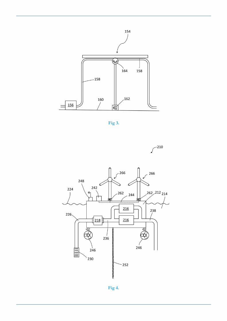
Fig 3.
Fig 4.

Fig 5.
Fig 6.