Embed Size (px)
Citation preview
Fundamentals of Modern Electrical Substations Part 2: Electrical Substation Auxiliary and Control Systems Course No: E03-013
Credit: 3 PDH
Boris Shvartsberg, Ph.D., P.E., P.M.P.
Continuing Education and Development, Inc. 9 Greyridge Farm Court Stony Point, NY 10980 P: (877) 322-5800 F: (877) 322-4774 [email protected]
© 2012 Boris Shvartsberg 1
Introduction Part 2 of the course “Fundamentals of Modern Electrical Substations” is concentrated on substation auxiliary and control systems which play a major role in allowing all station equipment to function properly, thus, fulfilling the main substation mission to support reliable and effective operation of power systems. The following auxiliary and control systems will be considered, including explanations of their mission, operation principles and arrangement:
Relay Protection Metering Systems Auxiliary AC/DC Power Systems Station Alarm and Remote Control Systems
Relay Protection This section provides an overview of relay protection philosophy. Its mission is to detect abnormal conditions in power systems, which would in the following actions:
Alarm Isolation of defective part of the system through operation of circuit interrupting
devices Any relay protection system should meet the following criteria:
Sensitivity: ability to detect all abnormal conditions for which the system is designed to detect
Selectivity: ability to initiate isolation of only the defected parts of the power system
Reliability: ability to operate with minimum failures of maloperations Economical effectiveness: ability to fulfill all necessary functions at a minimal
cost Improved redundancy: application of primary and back-up relay systems for
important equipment The following are the main components of a relay system:
Relays Control and test switches Auxiliary transformers Terminal blocks Cabling & wiring
© 2012 Boris Shvartsberg 2
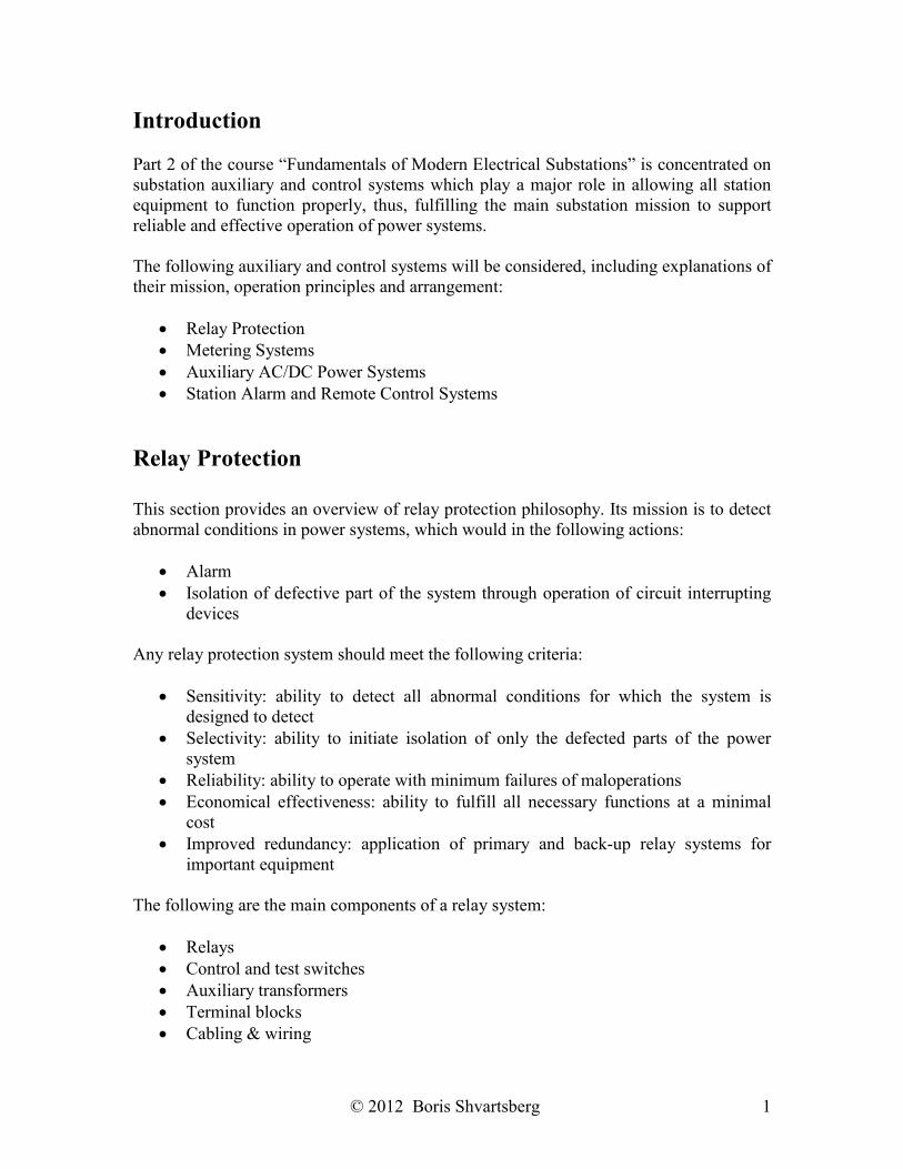
A relay is a device that receives information from instrument transformers about power system values (mostly currents and voltages), monitors the information, and acts on it when deviations from originally preset values (settings) occur. For example, an overcurrent relay will monitor the current in the circuit it is protecting, and adjusts the current values if they become higher than the original settings. Undervoltage relay will monitor the voltage and make the necessary adjustments when the voltage is lower than the original setting, etc. The following are the main types of relays:
Electromechanical Microprocessor
They may be installed on:
Relay racks Relay panels
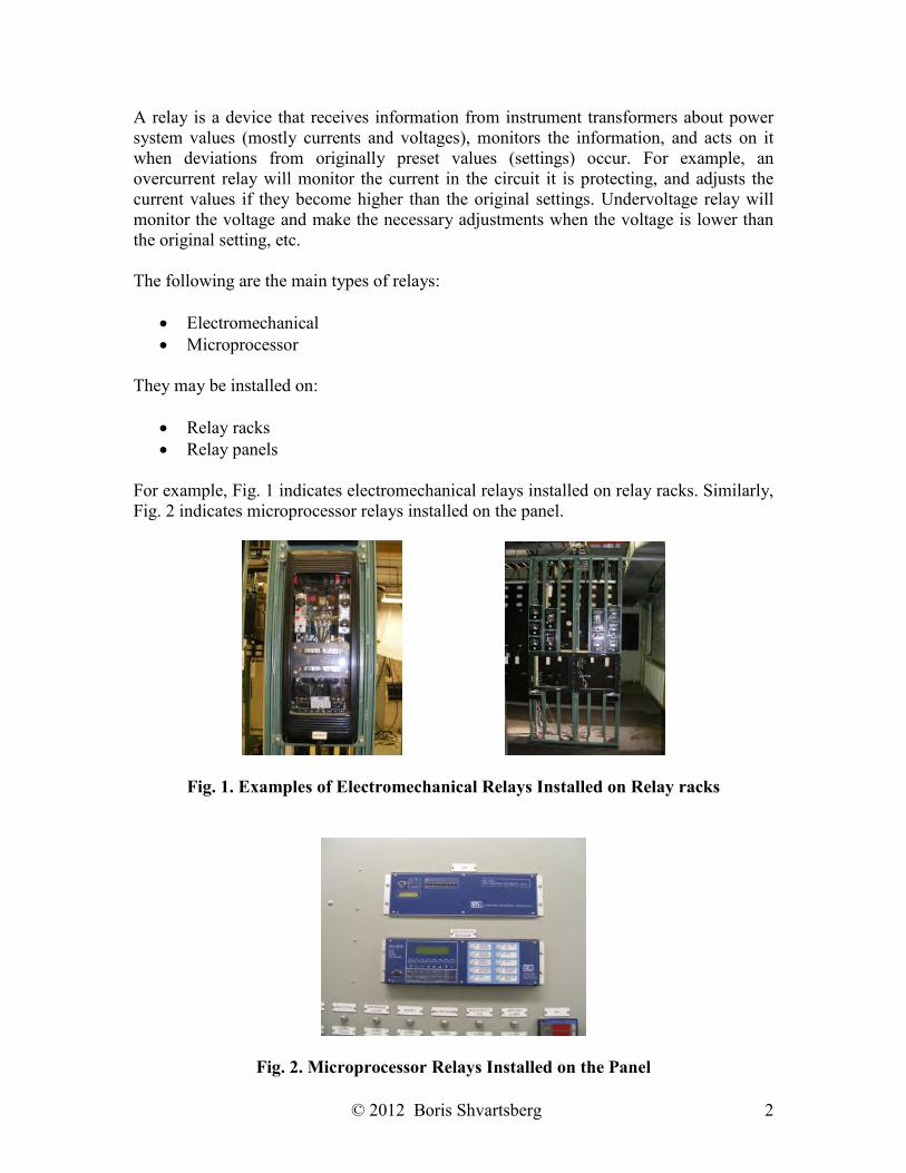
For example, Fig. 1 indicates electromechanical relays installed on relay racks. Similarly, Fig. 2 indicates microprocessor relays installed on the panel.
Fig. 1. Examples of Electromechanical Relays Installed on Relay racks
Fig. 2. Microprocessor Relays Installed on the Panel
© 2012 Boris Shvartsberg 3
There are numerous types of relay protection schemes with the most popular being:
Overcurrent Protection Distance Protection Differential Protection:
– Current differential protection – Voltage differential protection
Undervoltage Protection Overvoltage Protection Underfrequency Protection
Let’s consider some of these schemes in a greater detail starting with the most popular.
Overcurrent Protection Its objective is to detect current levels higher than a predetermined value (relay setting). The following are various types of overcurrent protection:
Instantaneous With time delay Directional – operates when:
– Measured current is higher than the setting – Power flows through the system element in a certain direction
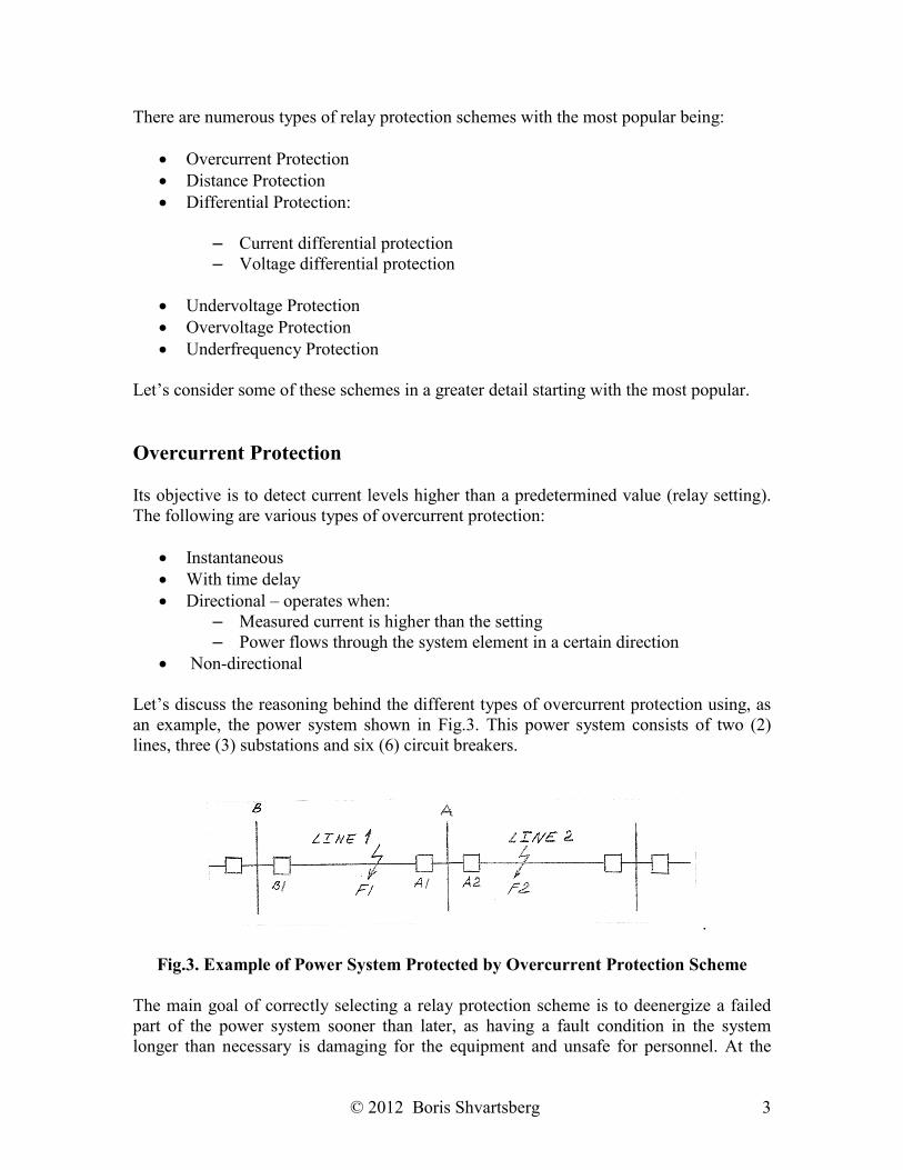
Non-directional Let’s discuss the reasoning behind the different types of overcurrent protection using, as an example, the power system shown in Fig.3. This power system consists of two (2) lines, three (3) substations and six (6) circuit breakers.
.
Fig.3. Example of Power System Protected by Overcurrent Protection Scheme The main goal of correctly selecting a relay protection scheme is to deenergize a failed part of the power system sooner than later, as having a fault condition in the system longer than necessary is damaging for the equipment and unsafe for personnel. At the
© 2012 Boris Shvartsberg 4
same time, the smallest possible part of the system (adjacent to the fault) should be taken out of service to reduce the number of customer outages. Given the aforementioned, let’s consider a fault F1 on the line L1, which connects substations A & B. The best way to deenergize the fault is to trip breaker B1 at substation B and A1 at substation A, and we want it to happen almost immediately (for modern relays, it may take a few cycles, let’s say, 6 cycles, which for a 60 Hz system amounts to 0.1 s). However, breaker A2 at Substation A will see the same current as breaker A1 and, unless we delay its tripping, it will open simultaneously with breaker A1, taking the whole substation A and its customers out of service, which is not acceptable. For that not to happen, a tripping of breaker A2 for faults on Line 1 should be delayed compared with the tripping of breaker A1, so A1 will trip first and the protection scheme will abort the tripping of A2, because the fault is not fed from substation A anymore. Another way to provide a selectivity for the operation of breakers A1 and A2 in this example is to use a directional scheme, which differentiates a direction of power flow from the bus into the line (allowed to trip) from another flow direction which is from the line into the bus (trip is blocked). Based on this principle, for example, for fault F2 on line L2 directional protection will allow only breaker A2 to trip, but A1 will stay closed leaving substation A in service, which is exactly what we wanted to achieve. The simplest overcurrent protection is installed on low voltage breakers that typically exist inside our homes. For example, if a receptacle and its wiring are designed for a 15A current, but we attempt to plug into this receptacle a device consuming 20A, the corresponding breaker will trip to avoid overheating of wiring that may result in a fire. Consequently, we will have to unplug the device causing the problem, find the breaker box and reset the breaker. Advantages of overcurrent protection are:
Simplicity Low cost
Disadvantages:
Difficulties with coordination between relay systems
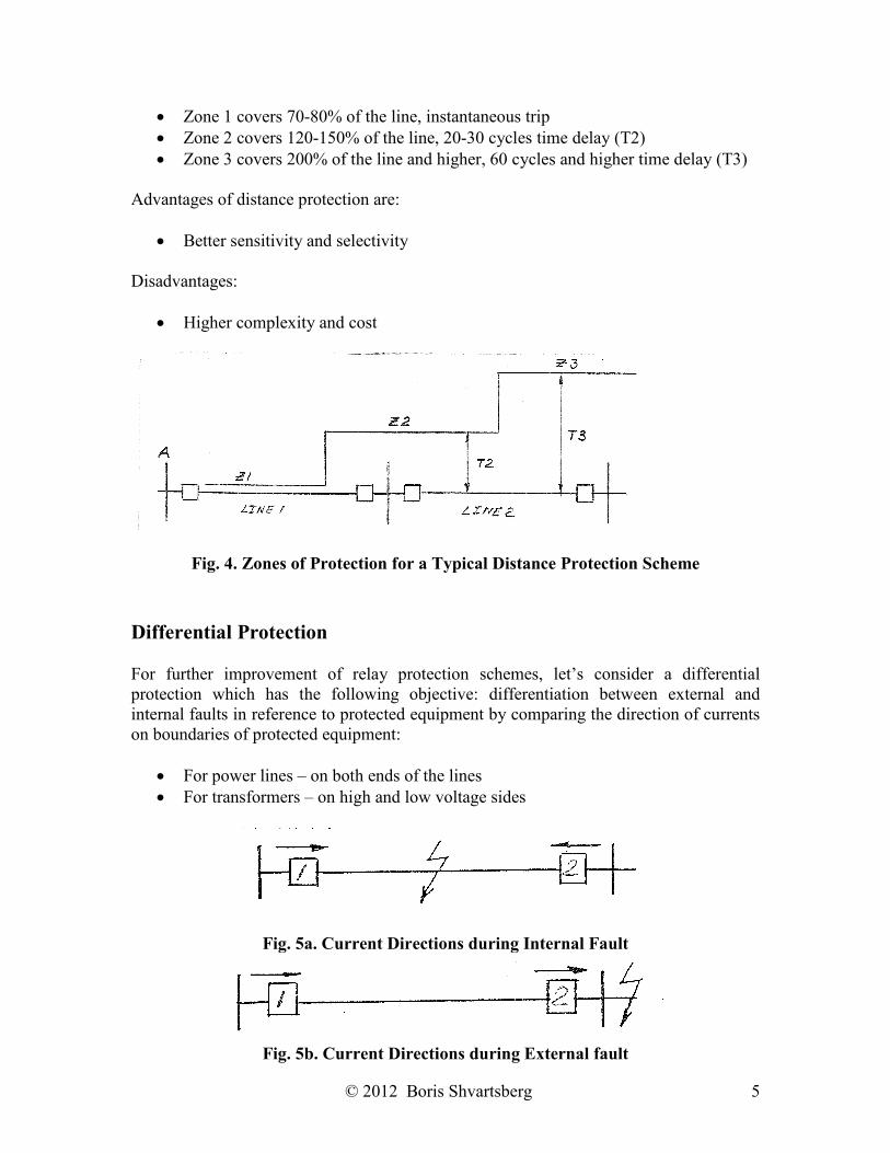
Distance Protection To address the coordination difficulties that may occur in overcurrent protection, a distance protection scheme may be used. The objective of this scheme is to detect the impedance levels that are lower than predetermined values (relay settings). The most popular type of distance protection is a step-distance relaying scheme for line protection, which consists of three distance relays or one 3-zone relay with the following zones of protection, shown in Fig. 4:
© 2012 Boris Shvartsberg 5
Zone 1 covers 70-80% of the line, instantaneous trip Zone 2 covers 120-150% of the line, 20-30 cycles time delay (T2) Zone 3 covers 200% of the line and higher, 60 cycles and higher time delay (T3)
Advantages of distance protection are:
Better sensitivity and selectivity
Disadvantages:
Higher complexity and cost
Fig. 4. Zones of Protection for a Typical Distance Protection Scheme
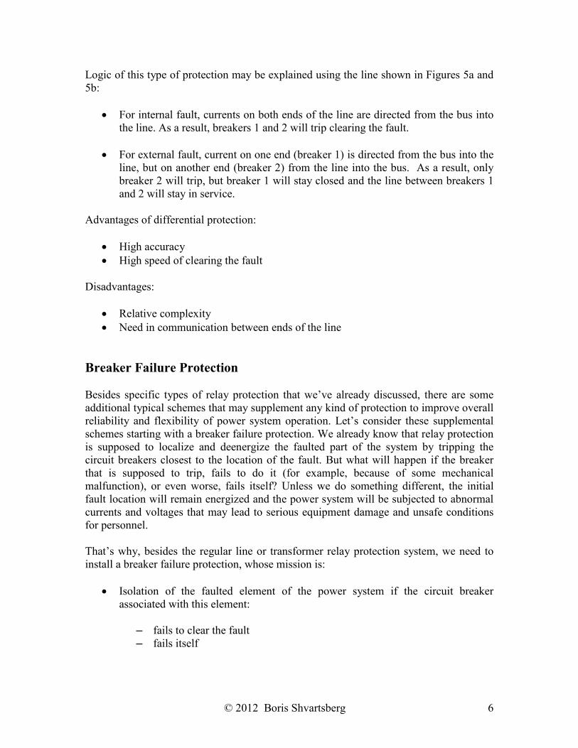
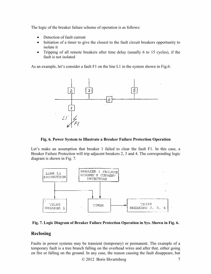
Differential Protection For further improvement of relay protection schemes, let’s consider a differential protection which has the following objective: differentiation between external and internal faults in reference to protected equipment by comparing the direction of currents on boundaries of protected equipment:
For power lines – on both ends of the lines For transformers – on high and low voltage sides
Fig. 5a. Current Directions during Internal Fault
Fig. 5b. Current Directions during External fault
© 2012 Boris Shvartsberg 6
Logic of this type of protection may be explained using the line shown in Figures 5a and 5b:
For internal fault, currents on both ends of the line are directed from the bus into the line. As a result, breakers 1 and 2 will trip clearing the fault.
For external fault, current on one end (breaker 1) is directed from the bus into the
line, but on another end (breaker 2) from the line into the bus. As a result, only breaker 2 will trip, but breaker 1 will stay closed and the line between breakers 1 and 2 will stay in service.
Advantages of differential protection:
High accuracy High speed of clearing the fault
Disadvantages:
Relative complexity Need in communication between ends of the line
Breaker Failure Protection Besides specific types of relay protection that we’ve already discussed, there are some additional typical schemes that may supplement any kind of protection to improve overall reliability and flexibility of power system operation. Let’s consider these supplemental schemes starting with a breaker failure protection. We already know that relay protection is supposed to localize and deenergize the faulted part of the system by tripping the circuit breakers closest to the location of the fault. But what will happen if the breaker that is supposed to trip, fails to do it (for example, because of some mechanical malfunction), or even worse, fails itself? Unless we do something different, the initial fault location will remain energized and the power system will be subjected to abnormal currents and voltages that may lead to serious equipment damage and unsafe conditions for personnel. That’s why, besides the regular line or transformer relay protection system, we need to install a breaker failure protection, whose mission is:
Isolation of the faulted element of the power system if the circuit breaker associated with this element:
– fails to clear the fault – fails itself
© 2012 Boris Shvartsberg 7
The logic of the breaker failure scheme of operation is as follows:
Detection of fault current Initiation of a timer to give the closest to the fault circuit breakers opportunity to
isolate it Tripping of all remote breakers after time delay (usually 6 to 15 cycles), if the
fault is not isolated
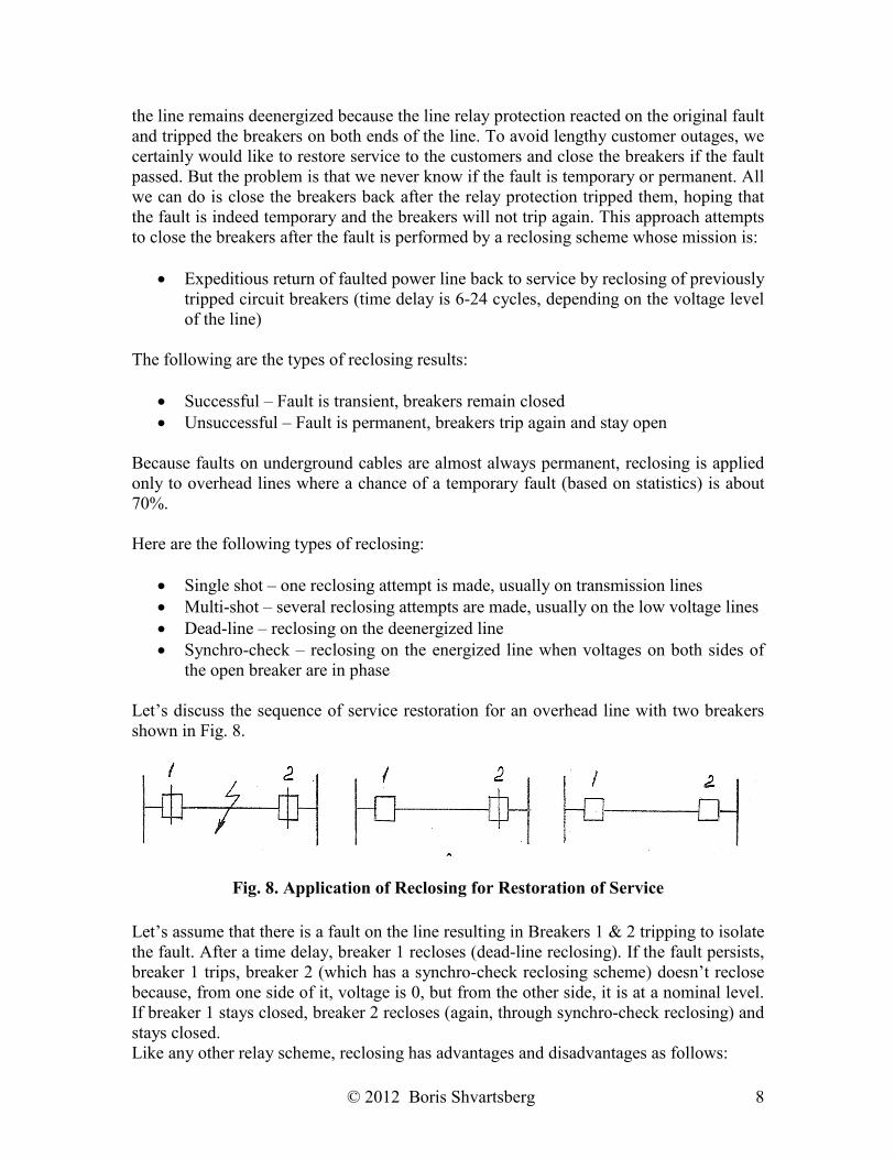
As an example, let’s consider a fault F1 on the line L1 in the system shown in Fig.6:
Fig. 6. Power System to Illustrate a Breaker Failure Protection Operation Let’s make an assumption that breaker 1 failed to clear the fault F1. In this case, a Breaker Failure Protection will trip adjacent breakers 2, 3 and 4. The corresponding logic diagram is shown in Fig. 7.
Fig. 7. Logic Diagram of Breaker Failure Protection Operation in Sys. Shown in Fig. 6.
Reclosing Faults in power systems may be transient (temporary) or permanent. The example of a temporary fault is a tree branch falling on the overhead wires and after that, either going on fire or falling on the ground. In any case, the reason causing the fault disappears, but
© 2012 Boris Shvartsberg 8
the line remains deenergized because the line relay protection reacted on the original fault and tripped the breakers on both ends of the line. To avoid lengthy customer outages, we certainly would like to restore service to the customers and close the breakers if the fault passed. But the problem is that we never know if the fault is temporary or permanent. All we can do is close the breakers back after the relay protection tripped them, hoping that the fault is indeed temporary and the breakers will not trip again. This approach attempts to close the breakers after the fault is performed by a reclosing scheme whose mission is:
Expeditious return of faulted power line back to service by reclosing of previously tripped circuit breakers (time delay is 6-24 cycles, depending on the voltage level of the line)
The following are the types of reclosing results:
Successful – Fault is transient, breakers remain closed Unsuccessful – Fault is permanent, breakers trip again and stay open
Because faults on underground cables are almost always permanent, reclosing is applied only to overhead lines where a chance of a temporary fault (based on statistics) is about 70%. Here are the following types of reclosing:
Single shot – one reclosing attempt is made, usually on transmission lines Multi-shot – several reclosing attempts are made, usually on the low voltage lines Dead-line – reclosing on the deenergized line Synchro-check – reclosing on the energized line when voltages on both sides of
the open breaker are in phase Let’s discuss the sequence of service restoration for an overhead line with two breakers shown in Fig. 8.
Fig. 8. Application of Reclosing for Restoration of Service
Let’s assume that there is a fault on the line resulting in Breakers 1 & 2 tripping to isolate the fault. After a time delay, breaker 1 recloses (dead-line reclosing). If the fault persists, breaker 1 trips, breaker 2 (which has a synchro-check reclosing scheme) doesn’t reclose because, from one side of it, voltage is 0, but from the other side, it is at a nominal level. If breaker 1 stays closed, breaker 2 recloses (again, through synchro-check reclosing) and stays closed. Like any other relay scheme, reclosing has advantages and disadvantages as follows:
© 2012 Boris Shvartsberg 9
Advantages: A high rate of successful reclosings (about 70% for overhead lines as
mentioned earlier) allows to minimize customer interruption and expeditiously return the power system back to normal operation
Disadvantages: If the fault is permanent, the circuit breaker has to interrupt a short
circuit current again, which puts additional stress on the breaker and may lead to breaker failure, necessity for additional maintenance, etc.
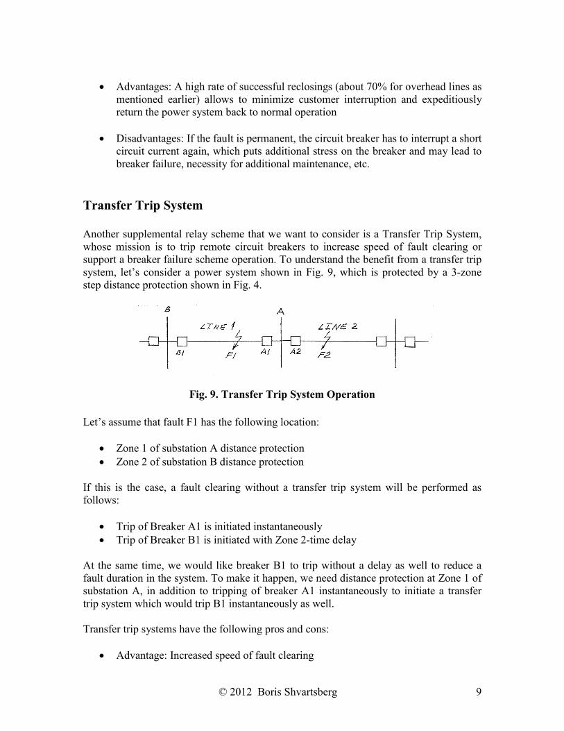
Transfer Trip System Another supplemental relay scheme that we want to consider is a Transfer Trip System, whose mission is to trip remote circuit breakers to increase speed of fault clearing or support a breaker failure scheme operation. To understand the benefit from a transfer trip system, let’s consider a power system shown in Fig. 9, which is protected by a 3-zone step distance protection shown in Fig. 4.
Fig. 9. Transfer Trip System Operation
Let’s assume that fault F1 has the following location:
Zone 1 of substation A distance protection Zone 2 of substation B distance protection
If this is the case, a fault clearing without a transfer trip system will be performed as follows:
Trip of Breaker A1 is initiated instantaneously Trip of Breaker B1 is initiated with Zone 2-time delay
At the same time, we would like breaker B1 to trip without a delay as well to reduce a fault duration in the system. To make it happen, we need distance protection at Zone 1 of substation A, in addition to tripping of breaker A1 instantaneously to initiate a transfer trip system which would trip B1 instantaneously as well. Transfer trip systems have the following pros and cons:
Advantage: Increased speed of fault clearing
© 2012 Boris Shvartsberg 10
Disadvantages:
– Need for additional equipment (transmitters, receivers, etc.) – Need for communication channels
Communication Channels for Relay Protection
As we saw before, there are several relay schemes that are based on exchange of information between different parts of the power system (both ends of power lines, for example), which require establishment of some kind of channels to provide a media for communication of relay protection systems. Specific areas of application for these communication channels are as follows:
Line differential protection schemes Transfer trip schemes
The following types of channels are currently used:
Power line carrier channels Fiber optic cables Pilot wire
Let’s discuss these channels in a greater detail. The first type is a power line carrier (PLC) channel, which is based on transmission of high frequency signals (30 – 300 kHz) via overhead and underground power line conductors. The main issue that should be resolved in order to transmit a high frequency signal over the same wires and cables, which are used for transmission and distribution of AC power with 60 Hz frequency, is to direct a strong communication signal into relay systems which are communicating instead of it being mixed up with power frequency, getting dispersed into power equipment and attenuated. To have it accomplished, the PLC system includes numerous components shown in Fig. 10.
© 2012 Boris Shvartsberg 11
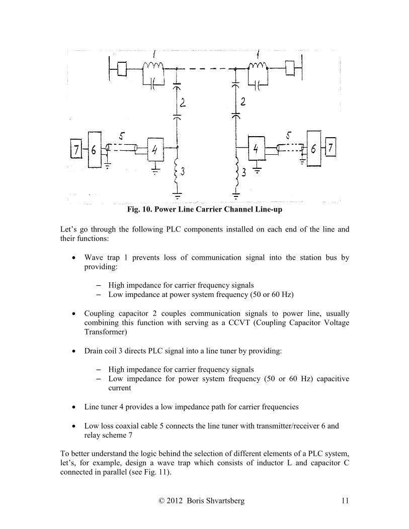
Fig. 10. Power Line Carrier Channel Line-up
Let’s go through the following PLC components installed on each end of the line and their functions:
Wave trap 1 prevents loss of communication signal into the station bus by providing:
– High impedance for carrier frequency signals – Low impedance at power system frequency (50 or 60 Hz)
Coupling capacitor 2 couples communication signals to power line, usually
combining this function with serving as a CCVT (Coupling Capacitor Voltage Transformer)
Drain coil 3 directs PLC signal into a line tuner by providing:
– High impedance for carrier frequency signals – Low impedance for power system frequency (50 or 60 Hz) capacitive
current
Line tuner 4 provides a low impedance path for carrier frequencies
Low loss coaxial cable 5 connects the line tuner with transmitter/receiver 6 and relay scheme 7
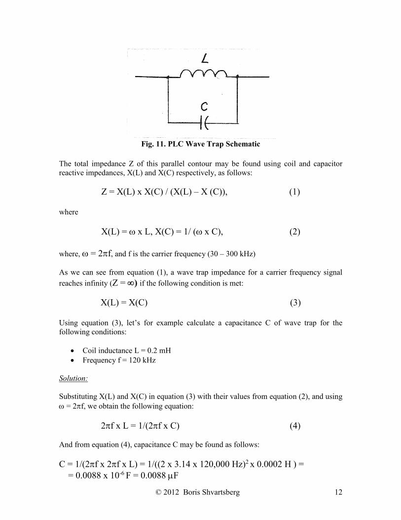
To better understand the logic behind the selection of different elements of a PLC system, let’s, for example, design a wave trap which consists of inductor L and capacitor C connected in parallel (see Fig. 11).
© 2012 Boris Shvartsberg 12
Fig. 11. PLC Wave Trap Schematic
The total impedance Z of this parallel contour may be found using coil and capacitor reactive impedances, X(L) and X(C) respectively, as follows:
Z = X(L) x X(C) / (X(L) – X (C)), (1) where
X(L) = x L, X(C) = 1/ ( x C), (2) where, = 2f, and f is the carrier frequency (30 – 300 kHz) As we can see from equation (1), a wave trap impedance for a carrier frequency signal
reaches infinity (Z = ) if the following condition is met:
X(L) = X(C) (3) Using equation (3), let’s for example calculate a capacitance C of wave trap for the following conditions:
Coil inductance L = 0.2 mH Frequency f = 120 kHz
Solution:
Substituting X(L) and X(C) in equation (3) with their values from equation (2), and using = 2f, we obtain the following equation:
2f x L = 1/(2f x C) (4) And from equation (4), capacitance C may be found as follows:
C = 1/(2f x 2f x L) = 1/((2 x 3.14 x 120,000 Hz)2 x 0.0002 H ) = = 0.0088 x 10⁻⁶ F = 0.0088 F
© 2012 Boris Shvartsberg 13
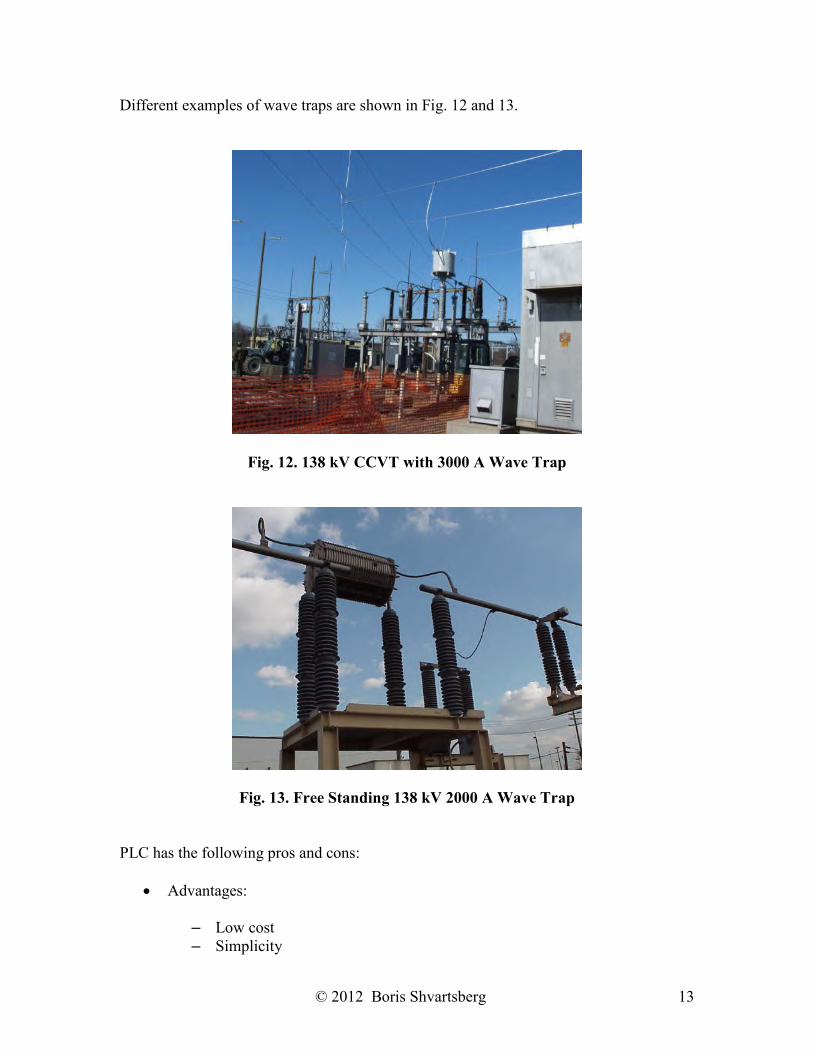
Different examples of wave traps are shown in Fig. 12 and 13.
Fig. 12. 138 kV CCVT with 3000 A Wave Trap
Fig. 13. Free Standing 138 kV 2000 A Wave Trap PLC has the following pros and cons:
Advantages:
– Low cost – Simplicity
© 2012 Boris Shvartsberg 14
Disadvantages:
– Attenuation of signal – Low speed of transmission
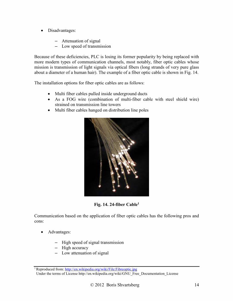
Because of these deficiencies, PLC is losing its former popularity by being replaced with more modern types of communication channels, most notably, fiber optic cables whose mission is transmission of light signals via optical fibers (long strands of very pure glass about a diameter of a human hair). The example of a fiber optic cable is shown in Fig. 14. The installation options for fiber optic cables are as follows:
Multi fiber cables pulled inside underground ducts As a FOG wire (combination of multi-fiber cable with steel shield wire)
strained on transmission line towers Multi fiber cables hanged on distribution line poles
Fig. 14. 24-fiber Cable1
Communication based on the application of fiber optic cables has the following pros and cons:
Advantages:
– High speed of signal transmission – High accuracy – Low attenuation of signal
1 Reproduced from: http://en.wikipedia.org/wiki/File:Fibreoptic.jpg Under the terms of License http://en.wikipedia.org/wiki/GNU_Free_Documentation_License
© 2012 Boris Shvartsberg 15
Disadvantages:
– High cost – Long restoration time after mechanical failure
The last type of communication channels to be mentioned is a pilot wire which is based on the use of actual (metallic) line installed between communicating relay systems. One of the pilot wire options is the use of a leased phone line for relay communication. Being in use for many years, relay schemes with a pilot wire communication became obsolete and, because of relatively low reliability of the channel, are frequently being replaced with systems based on the use of fiber optic cables for communication.
Metering Systems To operate and maintain power systems efficiently, it is very important to have accurate information about system values, and the mission of metering systems is to provide this information. However, real power system currents and voltages may reach very high numbers (thousands of amperes and volts respectively). To measure these values, they need to be reduced to much lower numbers that metering equipment can safely handle. For voltages a nominal value is usually 120 V, phase-to-neutral or phase-to-phase, and for currents nominal values are 1 A or 5 A. As discussed in Section 1 of this course, this transformation of currents and voltages is performed by instrument transformers which have their secondary windings connected to both relay and instrument equipment. All metering equipment may be split in the following functional groups:
Indicating – provides information about present values of electrical quantities, for example:
– Ammeters – measure current – Voltmeters – measure voltage – Ohmmeters – measure resistance, impedance – Wattmeters – measure active power – Varmeters – measure reactive power – Frequency meters
Recording – records the value of measured electrical quantities over a period of
time, for example:
– Watt-hour meters – record amount of active power spent or transferred over period of time
– Var-hour meters – record amount of reactive power spent or transferred over period of time
– Demand meters – record the maximum average load over period of time – Oscillographs, digital fault recorders – monitor currents and voltages at
different parts of the station to help with fault investigation
© 2012 Boris Shvartsberg 16
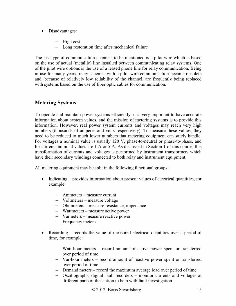
Based on how the measured information is presented, the following types of metering equipment should be mentioned:
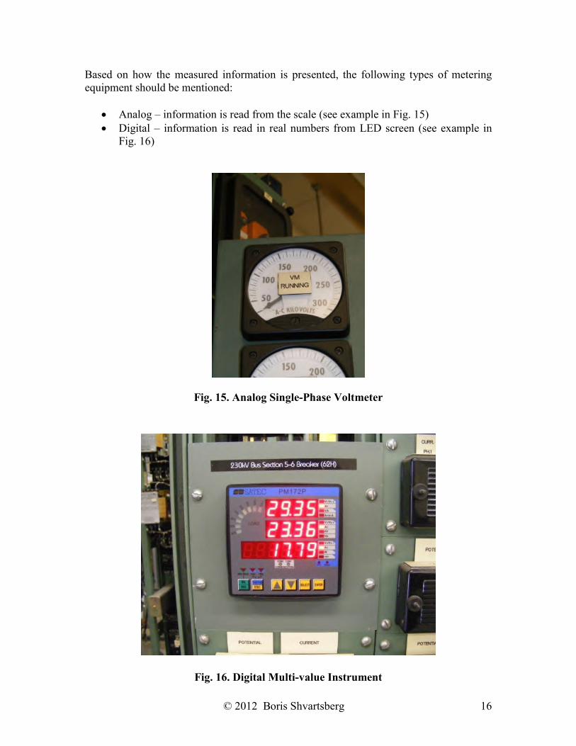
Analog – information is read from the scale (see example in Fig. 15) Digital – information is read in real numbers from LED screen (see example in
Fig. 16)
Fig. 15. Analog Single-Phase Voltmeter
Fig. 16. Digital Multi-value Instrument
© 2012 Boris Shvartsberg 17
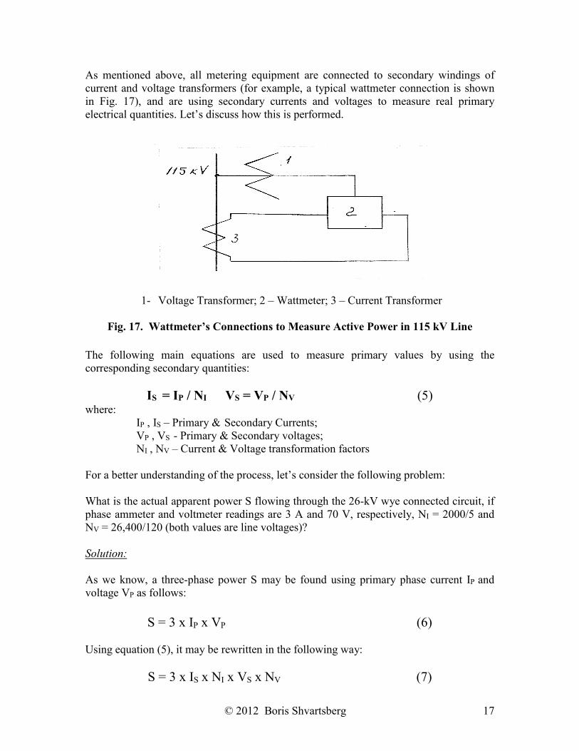
As mentioned above, all metering equipment are connected to secondary windings of current and voltage transformers (for example, a typical wattmeter connection is shown in Fig. 17), and are using secondary currents and voltages to measure real primary electrical quantities. Let’s discuss how this is performed.
1- Voltage Transformer; 2 – Wattmeter; 3 – Current Transformer
Fig. 17. Wattmeter’s Connections to Measure Active Power in 115 kV Line
The following main equations are used to measure primary values by using the corresponding secondary quantities:
IS = IP / NI VS = VP / NV (5) where:
IP , IS – Primary & Secondary Currents; VP , VS - Primary & Secondary voltages; NI , NV – Current & Voltage transformation factors
For a better understanding of the process, let’s consider the following problem: What is the actual apparent power S flowing through the 26-kV wye connected circuit, if phase ammeter and voltmeter readings are 3 A and 70 V, respectively, NI = 2000/5 and NV = 26,400/120 (both values are line voltages)? Solution: As we know, a three-phase power S may be found using primary phase current IP and voltage VP as follows:
S = 3 x IP x VP (6)
Using equation (5), it may be rewritten in the following way:
S = 3 x IS x NI x VS x NV (7)
© 2012 Boris Shvartsberg 18
Finally, plugging into equation (7) the actual numerical values given in the description of the problem, we obtain the following result: S = 3 x 3 x (2000/5) x 70 x (26,400/120) = 3 x 3 x 400 x 70 x 220 = 55.44 MVA
Auxiliary AC/DC Power Systems For a normal operation, many substation components (including both major and control equipment) require some low voltage power supply (AC or DC) which is provided by auxiliary AC and DC power systems, respectively. Let’s review them both starting with the AC system. Its main components are:
Station light and power transformers Automatic and manual transfer switches A.C. cabinets Cabling and wiring
The following are the examples of substation A.C. loads:
Lighting Heaters A.C. motors for substation equipment:
– Voltage regulators – Transformer cooling (fans, oil pumps, etc.) – Operators for switching equipment (breakers, circuit switchers, etc.)
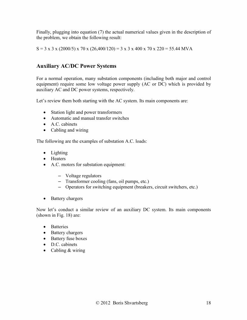
Battery chargers Now let’s conduct a similar review of an auxiliary DC system. Its main components (shown in Fig. 18) are:
Batteries Battery chargers Battery fuse boxes D.C. cabinets Cabling & wiring
© 2012 Boris Shvartsberg 19
Fig. 18. Substation Auxiliary DC Equipment The following are the examples of substation D.C. loads:
Circuit breaker trip coils Indicating lights Emergency lighting Relay protection control circuits Alarm circuits D.C. motors for substation equipment
Substation engineers should size all the components of both auxiliary AC and DC systems based on analysis of all substation auxiliary loads.
Substation Alarm and Remote Control Systems For effective and safe operation and maintenance of substations, utility companies’ personnel should be alerted about all abnormal system conditions. This mission is fulfilled by substation alarm systems. Alarms may be triggered by the following conditions:
Equipment parameter deviation from normal leading to a possible failure:
– High insulating oil temperature – Low oil level (oil leak) – High gas content in oil – Low isolating gas pressure (gas leak)
Switching equipment trip by relay protection because of:
– Fault in the system (short circuit, overvoltage, etc.) – Maloperation of relay protection
Station fire
© 2012 Boris Shvartsberg 20
Alarms may be either local to alert personnel located at the substation, or remote to make centralized operating personnel aware of abnormal conditions detected at the station.
The following are the main components of the alarm systems:
Sensors Visible alarms:
– Annunciators – Lights
Audible alarms:
– Bells – Horns
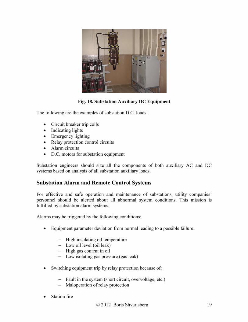
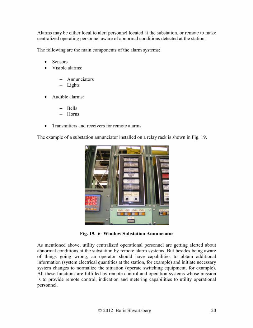
Transmitters and receivers for remote alarms The example of a substation annunciator installed on a relay rack is shown in Fig. 19.
Fig. 19. 6- Window Substation Annunciator As mentioned above, utility centralized operational personnel are getting alerted about abnormal conditions at the substation by remote alarm systems. But besides being aware of things going wrong, an operator should have capabilities to obtain additional information (system electrical quantities at the station, for example) and initiate necessary system changes to normalize the situation (operate switching equipment, for example). All these functions are fulfilled by remote control and operation systems whose mission is to provide remote control, indication and metering capabilities to utility operational personnel.
© 2012 Boris Shvartsberg 21
The main components of remote control and operation systems are as follows:
At substation: Remote terminal units (RTU’s) At dispatcher center: Centralized remote control unit
Interface: fiber optic cable, radio, phone line, etc.
Conclusion This course provided an overview of modern substation auxiliary and control systems, concentrating on their major role in supporting reliable and effective operation of power systems to enable you to:
Describe the mission of relay protection systems and criteria they need to meet List types of relay protection schemes Explain what breaker failure protection and reclosing are for Identify the main components of power line carrier communication system Understand the principle of signal transmission using fiber optic cable Know the difference between analogue and digital types of metering equipment Calculate a real value of electrical system parameters using readings of meters
and instruments Know the mission and main components of auxiliary A.C. and D.C. systems List the types of conditions triggering station alarm