Embed Size (px)
Citation preview
Functional Mockup Interface (FMI)
A General Standard for Model
Exchange and Simulator Coupling
Adeel Asghar and Willi Braun
Linköping University
University of Applied Sciene Bielefeld
2016-02-02
2016-02-02 2
• Need to SOLVE large integrated modeling and simulation
engineering problems
• Hundreds of simulation tools, different model formats
• Exchange dynamic models between different tools and define
tool coupling for dynamic system simulation environments.
• Two main approaches:
– 1. Export models from some tools,
import into other tools for simulation
– 2. Co-simulation of models in different tools
• Implementation Package Format: Functional Mockup Unit
(FMU)
• Solution: Functional Mockup Interface (FMI) standard
www.fmi-standard.org
FMI – Motivation 1
2016-02-02 3
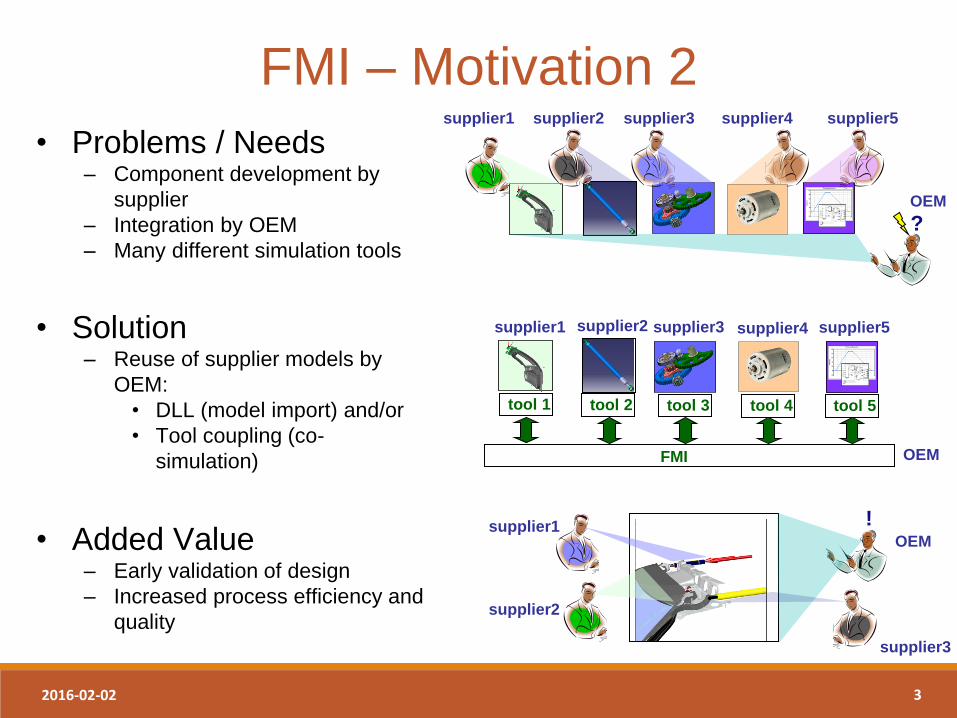
• Problems / Needs – Component development by
supplier
– Integration by OEM
– Many different simulation tools
FMI – Motivation 2
?
supplier1 supplier2 supplier3 supplier4 supplier5
OEM
supplier1
tool 1
supplier2 supplier3 supplier4 supplier5
tool 2 tool 3 tool 4 tool 5
FMI OEM
! supplier1
supplier2
supplier3
OEM
• Solution – Reuse of supplier models by
OEM:
• DLL (model import) and/or
• Tool coupling (co-
simulation)
• Added Value – Early validation of design
– Increased process efficiency and
quality
2016-02-02 4
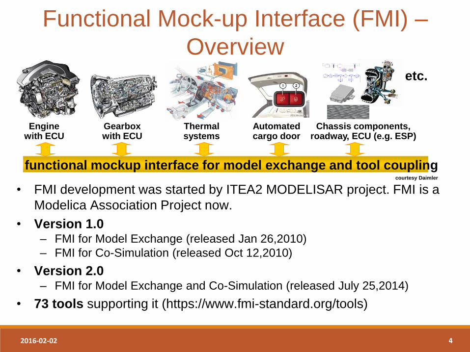
• FMI development was started by ITEA2 MODELISAR project. FMI is a
Modelica Association Project now.
• Version 1.0 – FMI for Model Exchange (released Jan 26,2010)
– FMI for Co-Simulation (released Oct 12,2010)
• Version 2.0 – FMI for Model Exchange and Co-Simulation (released July 25,2014)
• 73 tools supporting it (https://www.fmi-standard.org/tools)
Functional Mock-up Interface (FMI) –
Overview
Engine with ECU
Gearbox with ECU
Thermal systems
Automated cargo door
Chassis components, roadway, ECU (e.g. ESP)
etc.
functional mockup interface for model exchange and tool coupling courtesy Daimler
2016-02-02 5
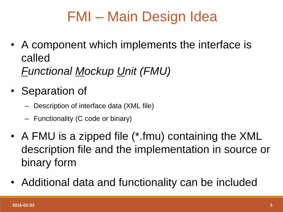
FMI – Main Design Idea
• A component which implements the interface is
called
Functional Mockup Unit (FMU)
• Separation of
– Description of interface data (XML file)
– Functionality (C code or binary)
• A FMU is a zipped file (*.fmu) containing the XML
description file and the implementation in source or
binary form
• Additional data and functionality can be included
2016-02-02 6
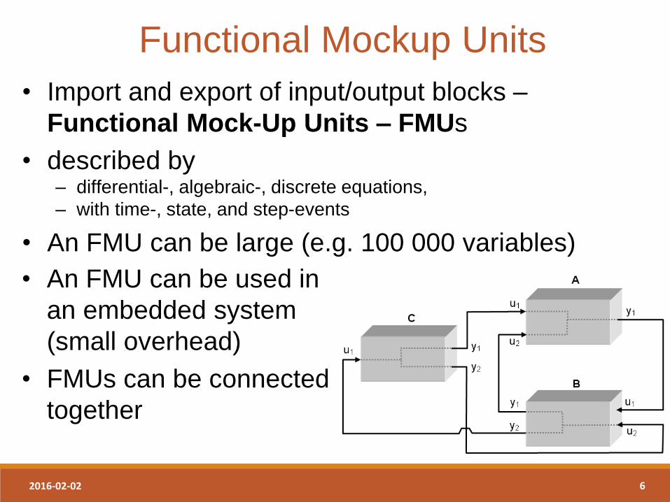
Functional Mockup Units
• Import and export of input/output blocks –
Functional Mock-Up Units – FMUs
• described by – differential-, algebraic-, discrete equations,
– with time-, state, and step-events
• An FMU can be large (e.g. 100 000 variables)
• An FMU can be used in
an embedded system
(small overhead)
• FMUs can be connected
together
2016-02-02 7
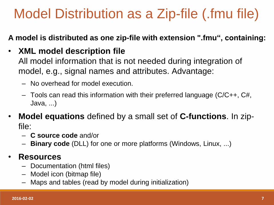
Model Distribution as a Zip-file (.fmu file)
A model is distributed as one zip-file with extension ".fmu“, containing:
• XML model description file
All model information that is not needed during integration of
model, e.g., signal names and attributes. Advantage:
– No overhead for model execution.
– Tools can read this information with their preferred language (C/C++, C#,
Java, ...)
• Model equations defined by a small set of C-functions. In zip-
file: – C source code and/or
– Binary code (DLL) for one or more platforms (Windows, Linux, ...)
• Resources – Documentation (html files)
– Model icon (bitmap file)
– Maps and tables (read by model during initialization)
2016-02-02 8
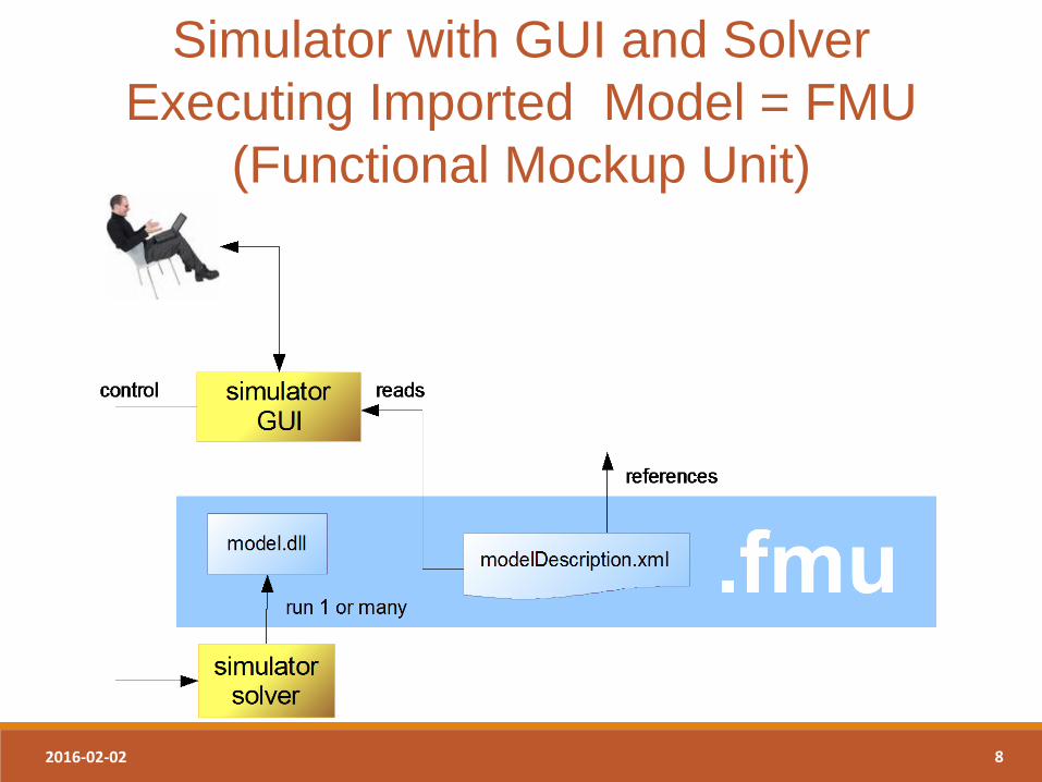
Simulator with GUI and Solver
Executing Imported Model = FMU
(Functional Mockup Unit)
Introduction to FMI 09/02/2016 9
FMU
Functional Mockup Unit
in more detail
2016-02-02 10
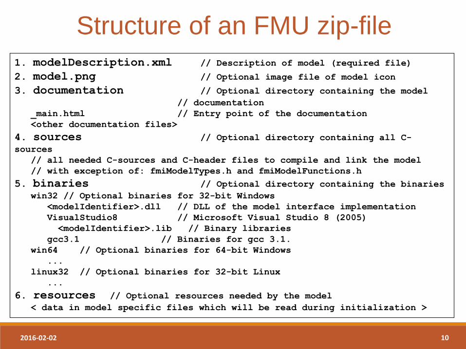
Structure of an FMU zip-file
1. modelDescription.xml // Description of model (required file)
2. model.png // Optional image file of model icon
3. documentation // Optional directory containing the model // documentation
_main.html // Entry point of the documentation
<other documentation files>
4. sources // Optional directory containing all C-sources
// all needed C-sources and C-header files to compile and link the model
// with exception of: fmiModelTypes.h and fmiModelFunctions.h
5. binaries // Optional directory containing the binaries win32 // Optional binaries for 32-bit Windows
<modelIdentifier>.dll // DLL of the model interface implementation
VisualStudio8 // Microsoft Visual Studio 8 (2005)
<modelIdentifier>.lib // Binary libraries
gcc3.1 // Binaries for gcc 3.1.
win64 // Optional binaries for 64-bit Windows
...
linux32 // Optional binaries for 32-bit Linux
...
6. resources // Optional resources needed by the model < data in model specific files which will be read during initialization >
2016-02-02 11
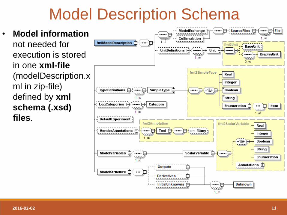
Model Description Schema • Model information
not needed for
execution is stored
in one xml-file
(modelDescription.x
ml in zip-file)
defined by xml
schema (.xsd)
files.
2016-02-02 12
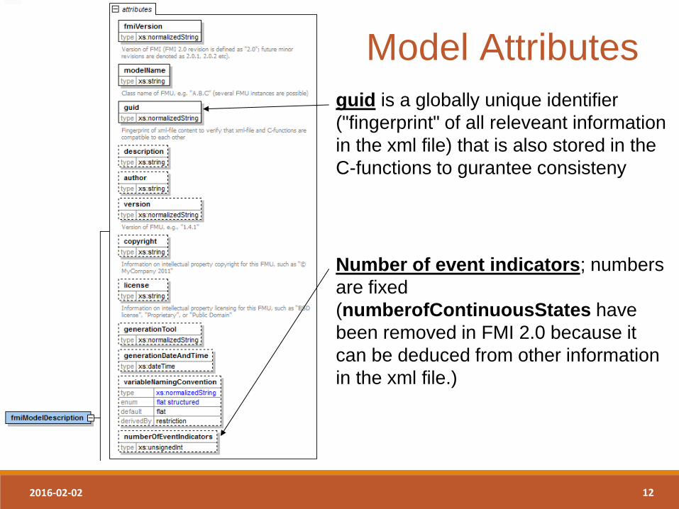
guid is a globally unique identifier
("fingerprint" of all releveant information
in the xml file) that is also stored in the
C-functions to gurantee consisteny
Number of event indicators; numbers
are fixed
(numberofContinuousStates have
been removed in FMI 2.0 because it
can be deduced from other information
in the xml file.)
Model Attributes
2016-02-02 13
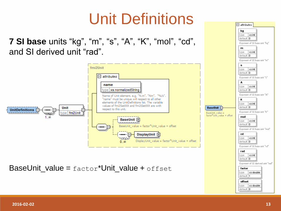
Unit Definitions
7 SI base units “kg”, “m”, “s”, “A”, “K”, “mol”, “cd”,
and SI derived unit “rad”.
BaseUnit_value = factor*Unit_value + offset
2016-02-02 14
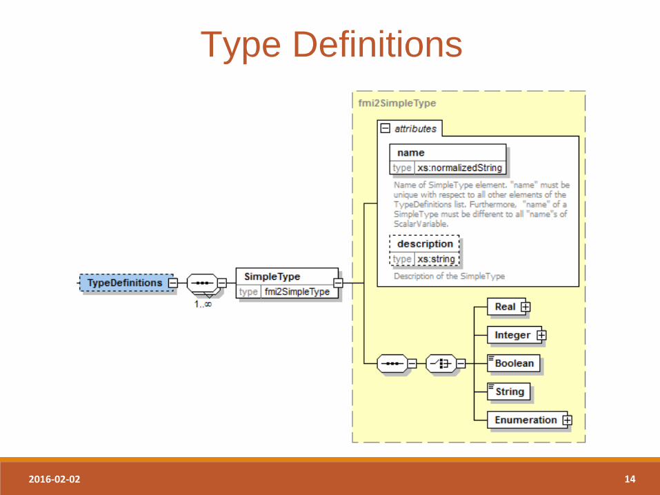
Type Definitions
2016-02-02 15
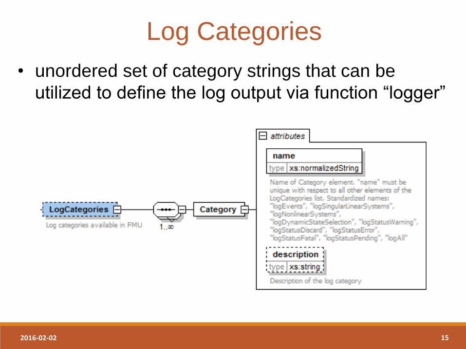
Log Categories
• unordered set of category strings that can be
utilized to define the log output via function “logger”
2016-02-02 16
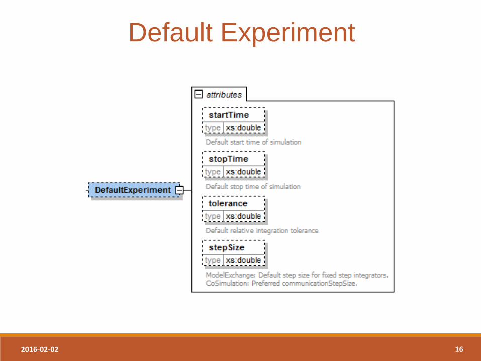
Default Experiment
2016-02-02 17
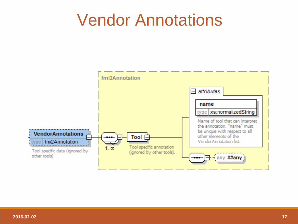
Vendor Annotations
2016-02-02 18
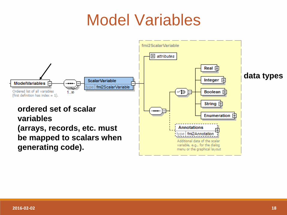
ordered set of scalar
variables
(arrays, records, etc. must
be mapped to scalars when
generating code).
data types
Model Variables
2016-02-02 19
...
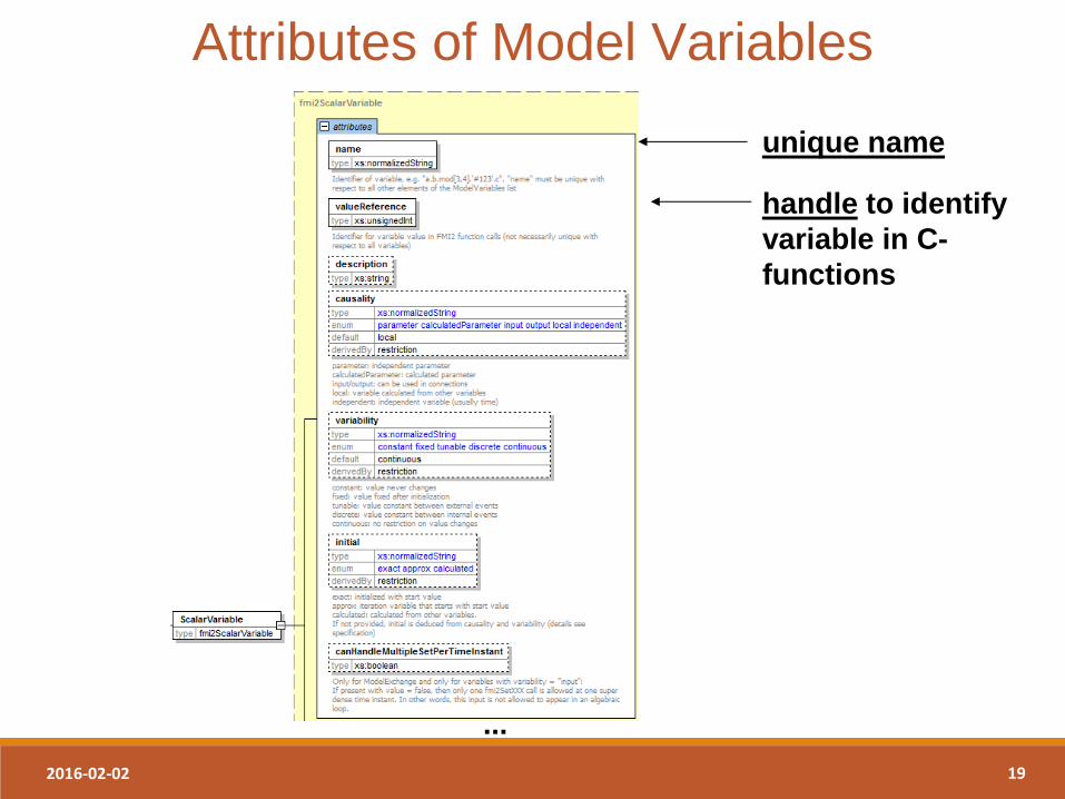
unique name
handle to identify
variable in C-
functions
Attributes of Model Variables
2016-02-02 20
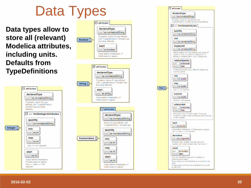
Data types allow to
store all (relevant)
Modelica attributes,
including units.
Defaults from
TypeDefinitions
Data Types
2016-02-02 21
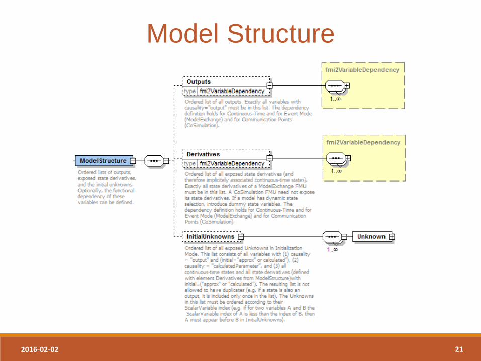
Model Structure
2016-02-02 22
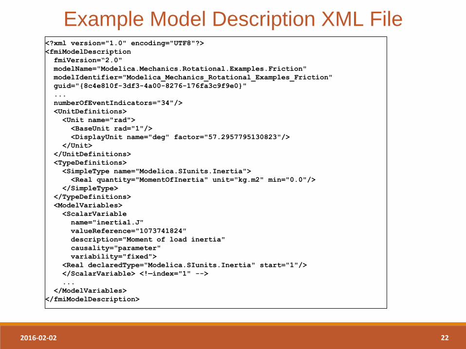
Example Model Description XML File <?xml version="1.0" encoding="UTF8"?>
<fmiModelDescription
fmiVersion=“2.0"
modelName="Modelica.Mechanics.Rotational.Examples.Friction"
modelIdentifier="Modelica_Mechanics_Rotational_Examples_Friction"
guid="{8c4e810f-3df3-4a00-8276-176fa3c9f9e0}"
...
numberOfEventIndicators="34"/>
<UnitDefinitions>
<Unit name="rad">
<BaseUnit rad="1"/>
<DisplayUnit name="deg" factor="57.2957795130823"/>
</Unit>
</UnitDefinitions>
<TypeDefinitions>
<SimpleType name="Modelica.SIunits.Inertia">
<Real quantity="MomentOfInertia" unit="kg.m2" min="0.0"/>
</SimpleType>
</TypeDefinitions>
<ModelVariables>
<ScalarVariable
name="inertia1.J"
valueReference="1073741824"
description="Moment of load inertia"
causality="parameter"
variability="fixed">
<Real declaredType="Modelica.SIunits.Inertia" start="1"/>
</ScalarVariable> <!—index="1" -->
...
</ModelVariables>
</fmiModelDescription>

Introduction to FMI 09/02/2016 23
FMI for Model Exchange
2016-02-02 24
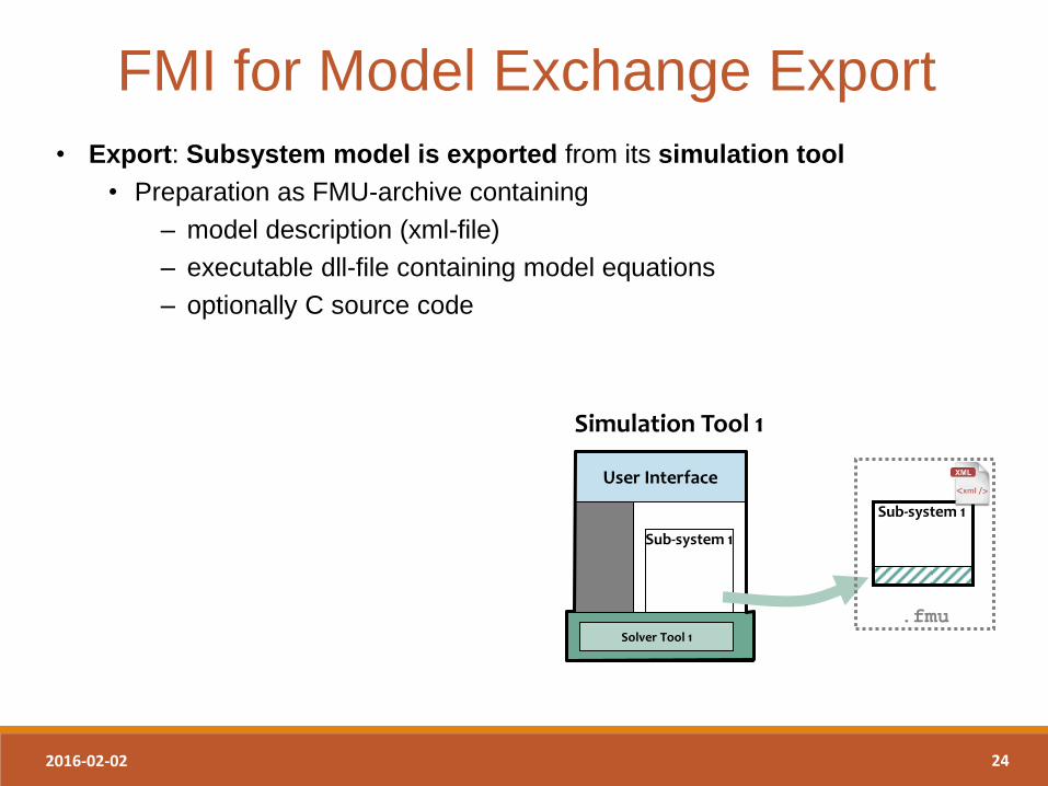
FMI for Model Exchange Export
• Export: Subsystem model is exported from its simulation tool
• Preparation as FMU-archive containing
– model description (xml-file)
– executable dll-file containing model equations
– optionally C source code
Sub-system 1
User Interface
Simulation Tool 1
Solver Tool 1
Sub-system 1
.fmu
2016-02-02 25
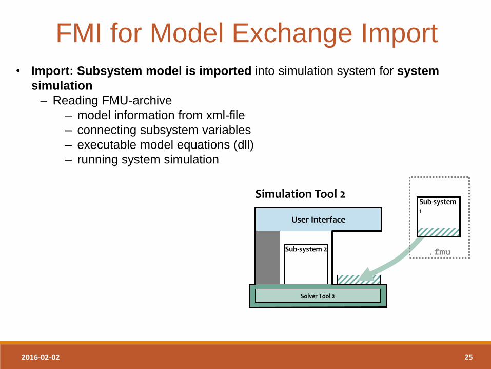
FMI for Model Exchange Import
• Import: Subsystem model is imported into simulation system for system
simulation
– Reading FMU-archive
– model information from xml-file
– connecting subsystem variables
– executable model equations (dll)
– running system simulation
User Interface
Sub-system 2
Simulation Tool 2
Solver Tool 2
Sub-system 1
.fmu
2016-02-02 26
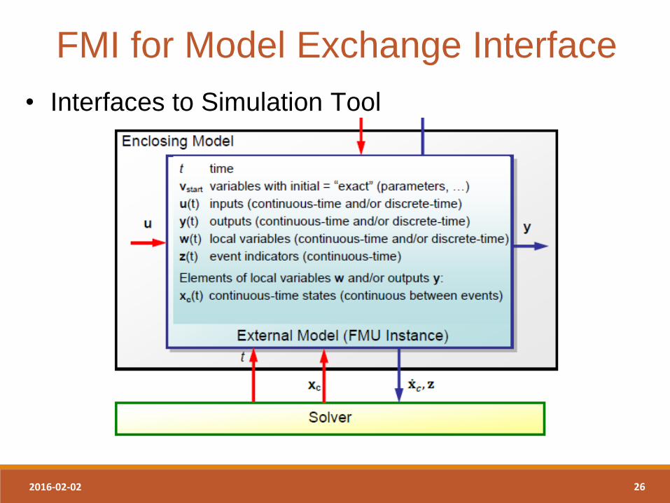
FMI for Model Exchange Interface
• Interfaces to Simulation Tool
2016-02-02 27
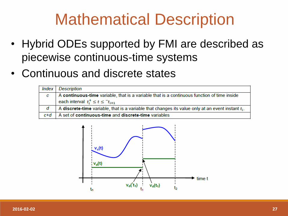
Mathematical Description
• Hybrid ODEs supported by FMI are described as
piecewise continuous-time systems
• Continuous and discrete states
2016-02-02 28
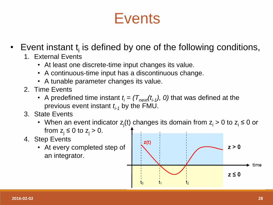
Events
• Event instant ti is defined by one of the following conditions, 1. External Events
• At least one discrete-time input changes its value.
• A continuous-time input has a discontinuous change.
• A tunable parameter changes its value.
2. Time Events
• A predefined time instant ti = (Tnext(ti-1), 0) that was defined at the
previous event instant ti-1 by the FMU.
3. State Events
• When an event indicator zj(t) changes its domain from zj > 0 to zj ≤ 0 or
from zj ≤ 0 to zj > 0.
4. Step Events
• At every completed step of
an integrator.
2016-02-02 29
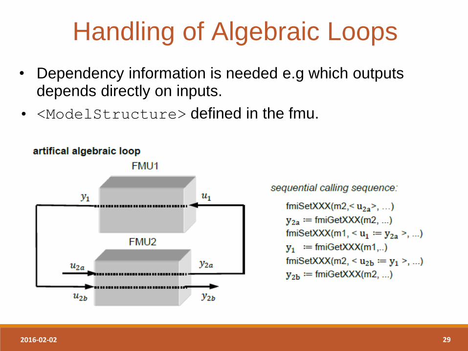
Handling of Algebraic Loops
• Dependency information is needed e.g which outputs depends directly on inputs.
• <ModelStructure> defined in the fmu.
2016-02-02 30
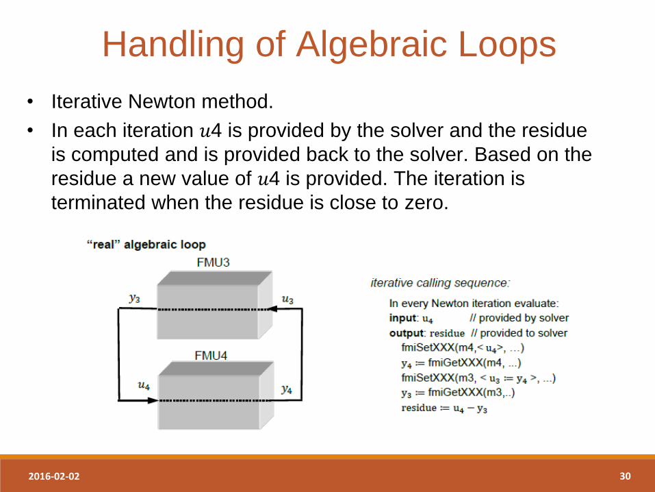
Handling of Algebraic Loops
• Iterative Newton method.
• In each iteration 𝑢4 is provided by the solver and the residue
is computed and is provided back to the solver. Based on the
residue a new value of 𝑢4 is provided. The iteration is
terminated when the residue is close to zero.
2016-02-02 31
Model Exchange FMU Solution
In order to solve a FMI model we need to split its
solution process into different phases,
• Initialization Mode – Compute initial values of states at time t0.
• Continuous-time Mode – Compute continuous-time variables between events.
– Discrete-time variables remains fixed.
• Event Mode – Compute new values for continuous-time and discrete-time variables.
2016-02-02 32
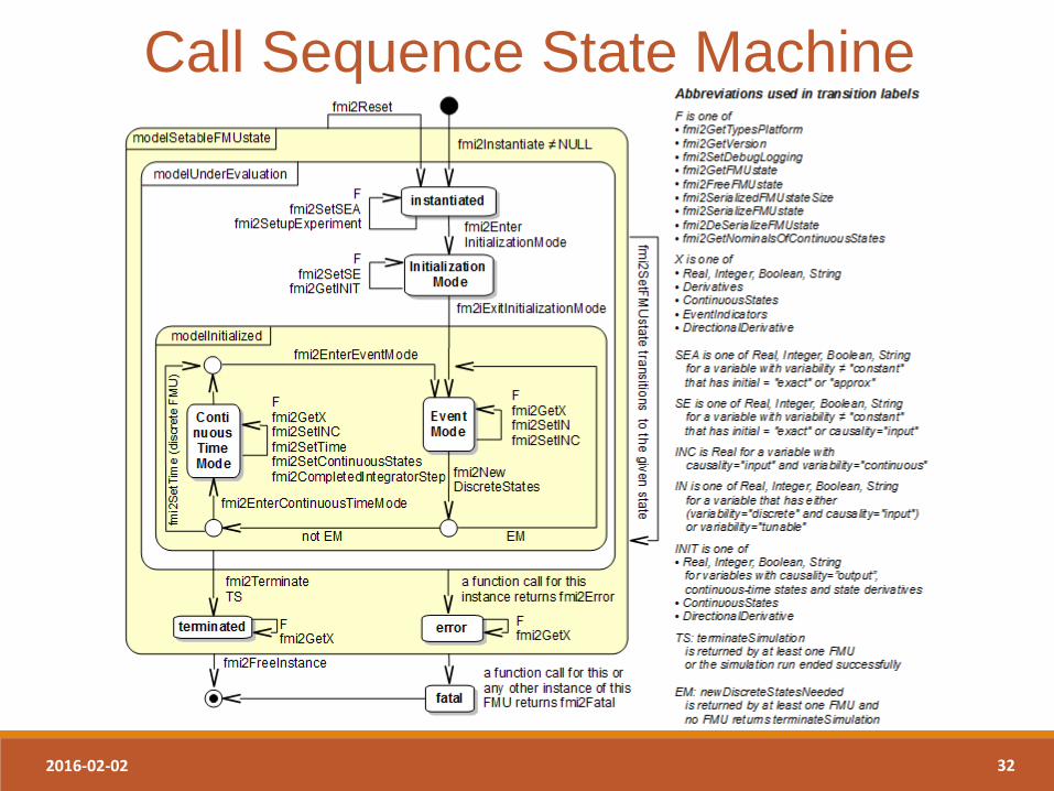
Call Sequence State Machine
Introduction to FMI 09/02/2016 33
FMI for Co-Simulation
2016-02-02 34
FMI for Co-Simulation • Master/slave architecture
• Support of simple and sophisticated coupling
algorithms: – Iterative and straight forward algorithms
– Constant and variable communication step size
• Allows (higher order) interpolation of continuous
inputs
• Support of local and distributed co-simulation
scenarios
• FMI for Co-Simulation does not define: – Co-simulation algorithms
– Communication technology for distributed scenarios
2016-02-02 35
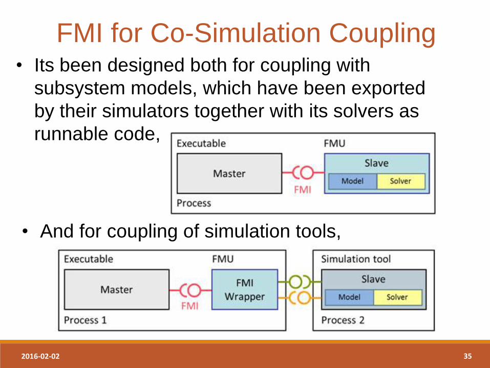
FMI for Co-Simulation Coupling • Its been designed both for coupling with
subsystem models, which have been exported
by their simulators together with its solvers as
runnable code,
• And for coupling of simulation tools,
2016-02-02 36
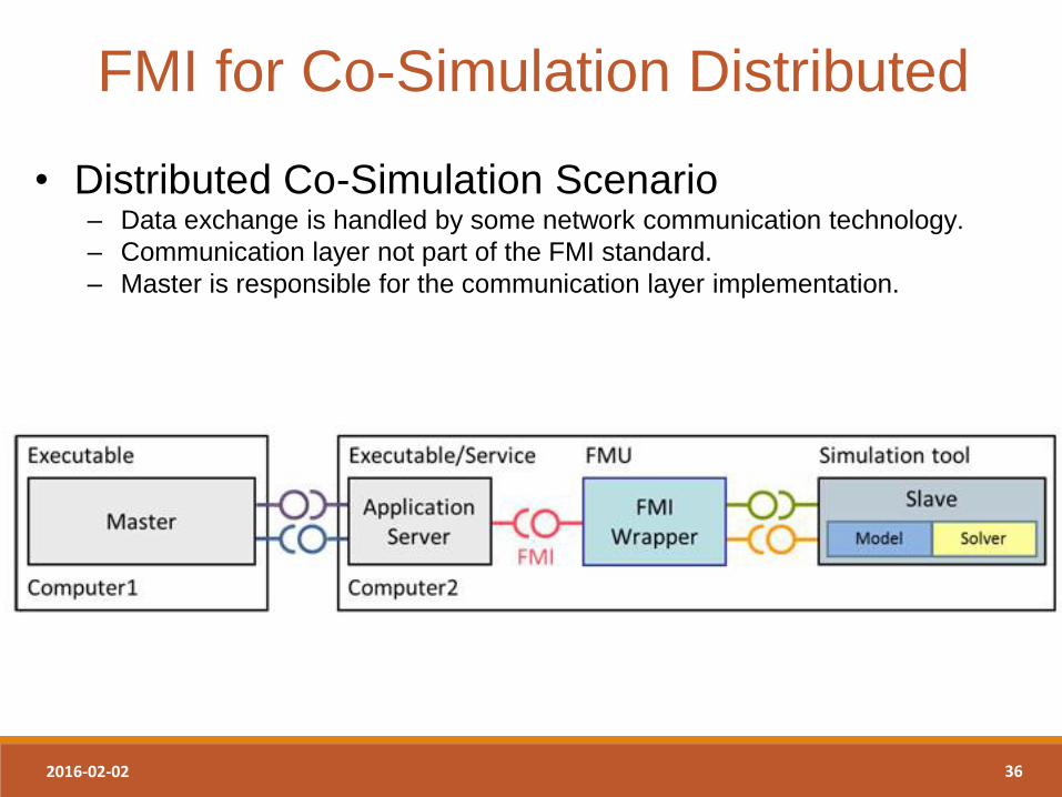
FMI for Co-Simulation Distributed
• Distributed Co-Simulation Scenario – Data exchange is handled by some network communication technology.
– Communication layer not part of the FMI standard.
– Master is responsible for the communication layer implementation.
2016-02-02 37
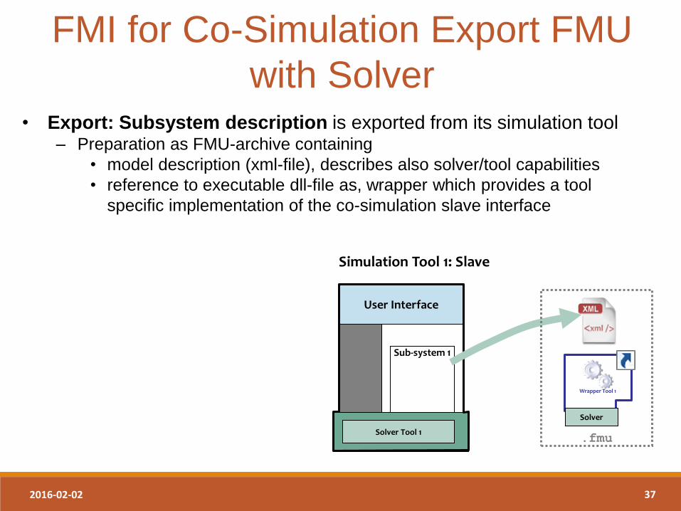
• Export: Subsystem description is exported from its simulation tool – Preparation as FMU-archive containing
• model description (xml-file), describes also solver/tool capabilities
• reference to executable dll-file as, wrapper which provides a tool
specific implementation of the co-simulation slave interface
FMI for Co-Simulation Export FMU
with Solver
Sub-system 1
User Interface
Simulation Tool 1: Slave
Solver Tool 1 .fmu
Wrapper Tool 1
Solver
2016-02-02 38
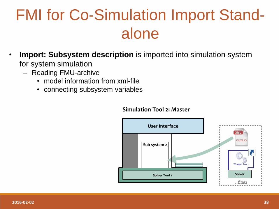
FMI for Co-Simulation Import Stand-
alone
• Import: Subsystem description is imported into simulation system
for system simulation – Reading FMU-archive
• model information from xml-file
• connecting subsystem variables
User Interface
Sub-system 2
Simulation Tool 2: Master
Solver Tool 2
.fmu
Wrapper Tool 1
Solver
2016-02-02 39
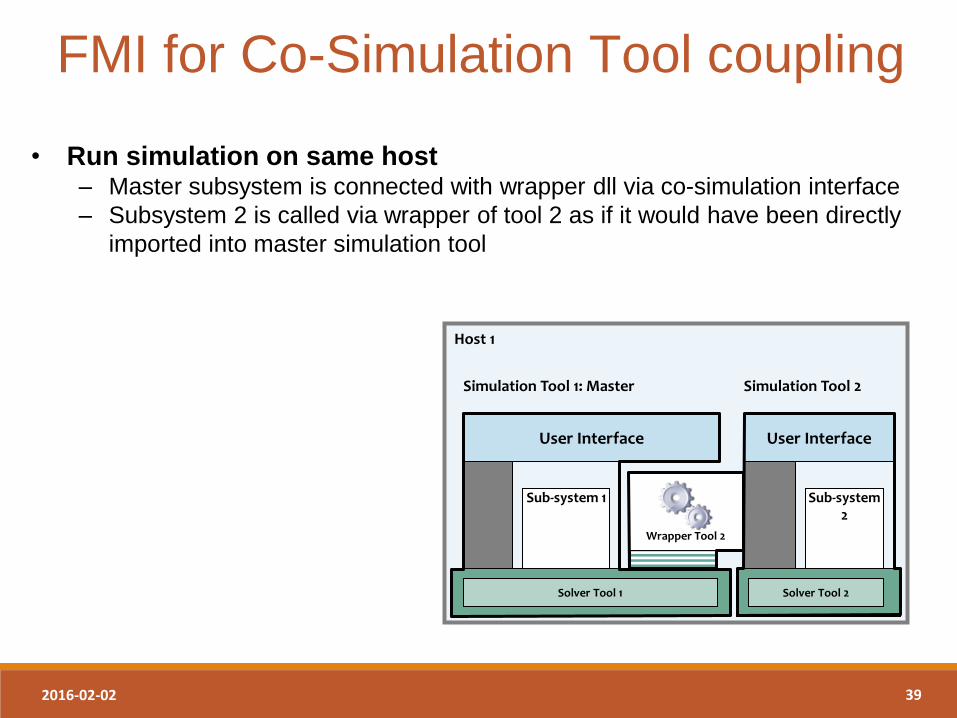
• Run simulation on same host – Master subsystem is connected with wrapper dll via co-simulation interface
– Subsystem 2 is called via wrapper of tool 2 as if it would have been directly
imported into master simulation tool
FMI for Co-Simulation Tool coupling
Host 1
User Interface
Sub-system 1
Simulation Tool 1: Master
Solver Tool 1
Sub-system 2
User Interface
Simulation Tool 2
Solver Tool 2
Wrapper Tool 2
2016-02-02 40
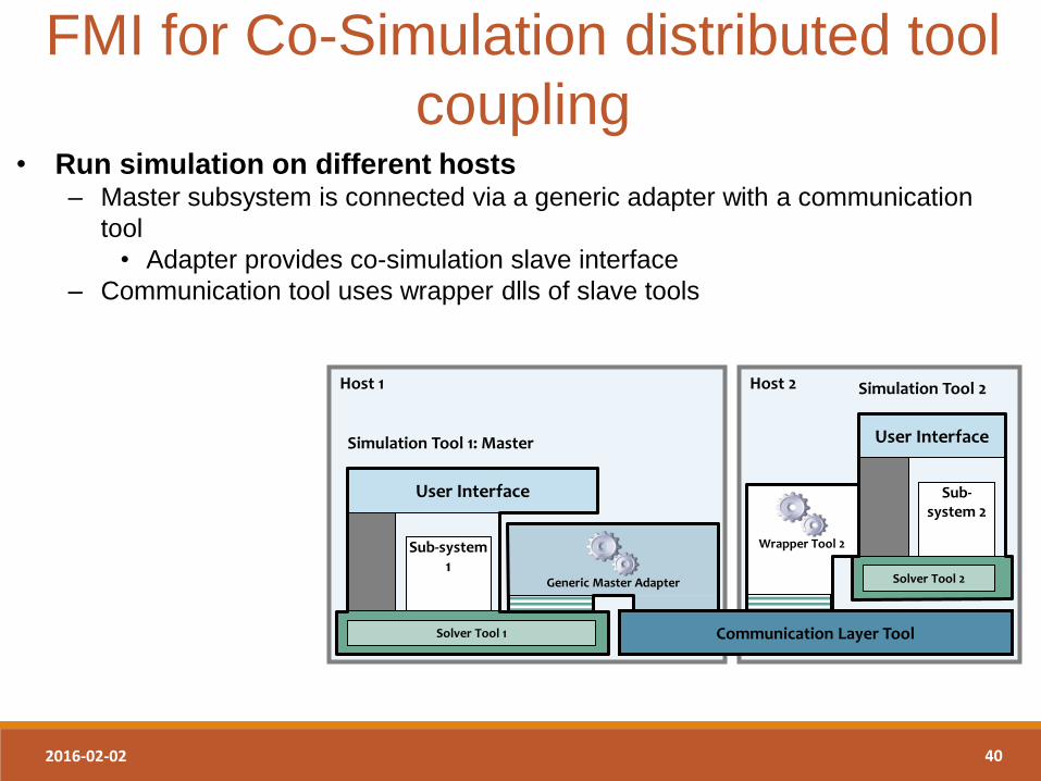
FMI for Co-Simulation distributed tool
coupling • Run simulation on different hosts
– Master subsystem is connected via a generic adapter with a communication
tool
• Adapter provides co-simulation slave interface
– Communication tool uses wrapper dlls of slave tools
Host 2 Host 1
User Interface
Sub-system 1
Simulation Tool 1: Master
Solver Tool 1 Communication Layer Tool
Generic Master Adapter
Sub-system 2
User Interface
Simulation Tool 2
Solver Tool 2
Wrapper Tool 2
2016-02-02 41
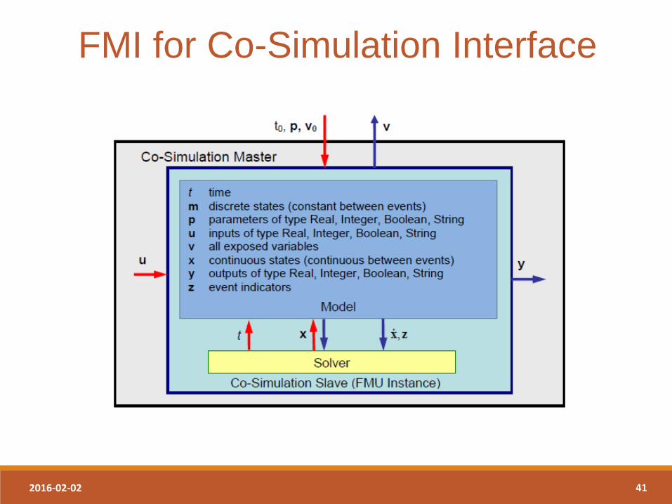
FMI for Co-Simulation Interface

2016-02-02 42
Mathematical Description
For co-simulation two basic groups of functions have
to be realized:
1. functions for the data exchange between
subsystems and
2. functions for algorithmic issues to synchronize the
simulation of all subsystems and to proceed in
communication steps tci → tci+1 from initial time
tc0 := tstart to end time tcN := tstop.
2016-02-02 43
Common Master Algorithm
• Stops at each communication point of all slaves
• Collects the output from all slaves
• Evaluates the slaves inputs
• Distributes the inputs to the slaves and continue
simulation with the next communication step with
fixed communication step size
• Slave’s solver is used for integration
FMI for Co-Simulation is designed to support a very
general class of master algorithms but it does not
define the master algorithm itself.
2016-02-02 44
Sophisticated Master Algorithm
Capability flags,
• Variable communication step size
• Repeat a rejected communication step tci → tci+1
with reduced communication step size
• Provide derivatives w.r.t. time of outputs to allow
interpolation
• Provides Jacobians.
2016-02-02 45
Co-Simulation FMU Solution
In order to solve a FMI co-simulation model we need
to split its solution process into two phases,
• Initialization Mode – Compute initial values of internal variables of the slave at time t0.
• Step Mode – Compute the values of all (real) continuous-time variables at communication
points.
2016-02-02 46
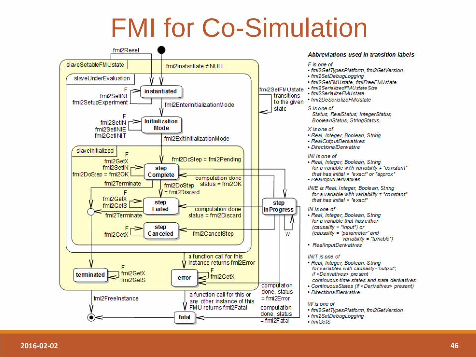
FMI for Co-Simulation
Introduction to FMI 09/02/2016 47
FMI
OpenModelica Implementation
and Applications
2016-02-02 48
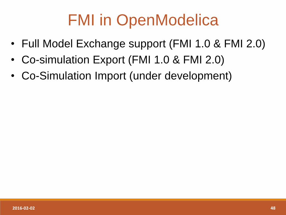
• Full Model Exchange support (FMI 1.0 & FMI 2.0)
• Co-simulation Export (FMI 1.0 & FMI 2.0)
• Co-Simulation Import (under development)
FMI in OpenModelica
2016-02-02 49
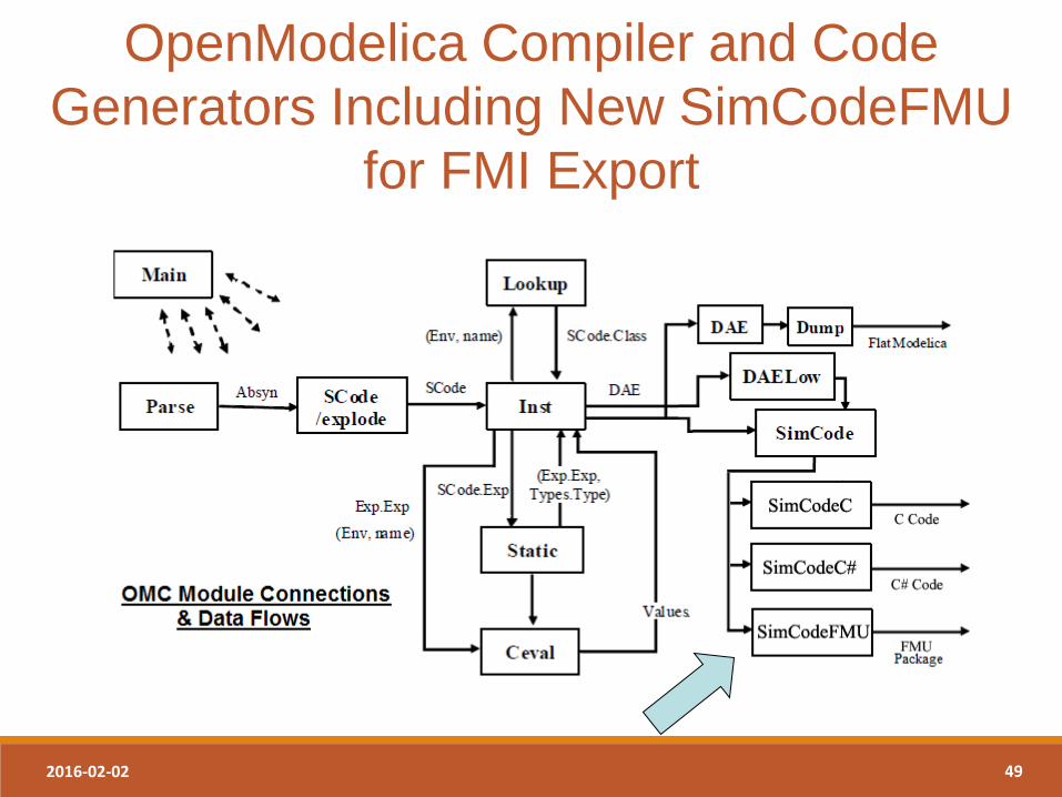
OpenModelica Compiler and Code
Generators Including New SimCodeFMU
for FMI Export
2016-02-02 50
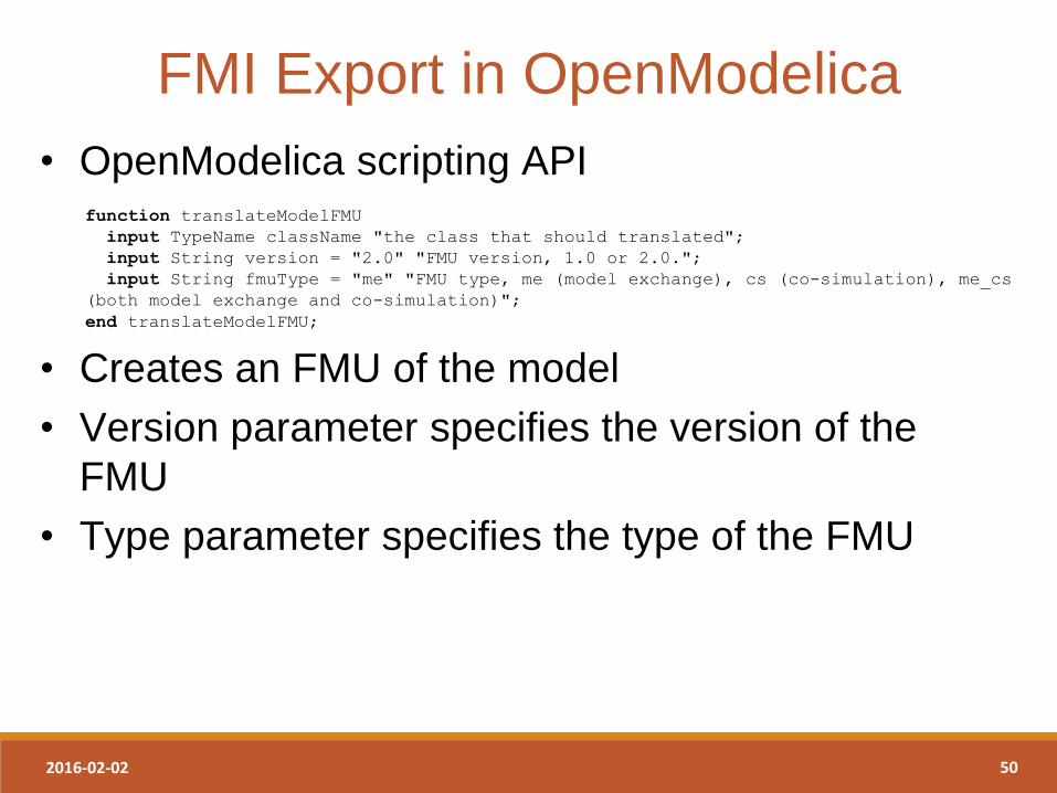
• OpenModelica scripting API
function translateModelFMU
input TypeName className "the class that should translated";
input String version = "2.0" "FMU version, 1.0 or 2.0.";
input String fmuType = "me" "FMU type, me (model exchange), cs (co-simulation), me_cs
(both model exchange and co-simulation)";
end translateModelFMU;
• Creates an FMU of the model
• Version parameter specifies the version of the
FMU
• Type parameter specifies the type of the FMU
FMI Export in OpenModelica
2016-02-02 51
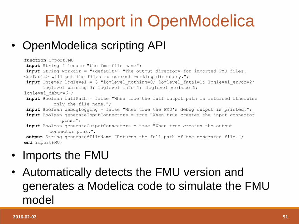
• OpenModelica scripting API
function importFMU
input String filename "the fmu file name";
input String workdir = "<default>" "The output directory for imported FMU files.
<default> will put the files to current working directory.";
input Integer loglevel = 3 "loglevel_nothing=0; loglevel_fatal=1; loglevel_error=2;
loglevel_warning=3; loglevel_info=4; loglevel_verbose=5;
loglevel_debug=6";
input Boolean fullPath = false "When true the full output path is returned otherwise
only the file name.";
input Boolean debugLogging = false "When true the FMU's debug output is printed.";
input Boolean generateInputConnectors = true "When true creates the input connector
pins.";
input Boolean generateOutputConnectors = true "When true creates the output
connector pins.";
output String generatedFileName "Returns the full path of the generated file.";
end importFMU;
• Imports the FMU
• Automatically detects the FMU version and
generates a Modelica code to simulate the FMU
model
FMI Import in OpenModelica
2016-02-02 52
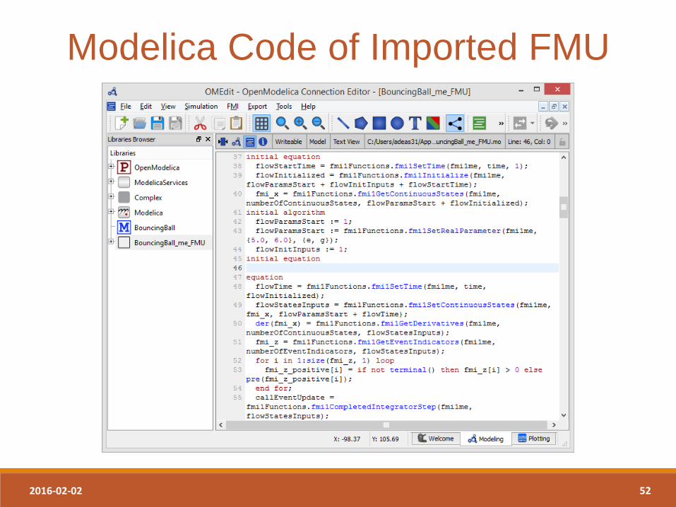
Modelica Code of Imported FMU
2016-02-02 53
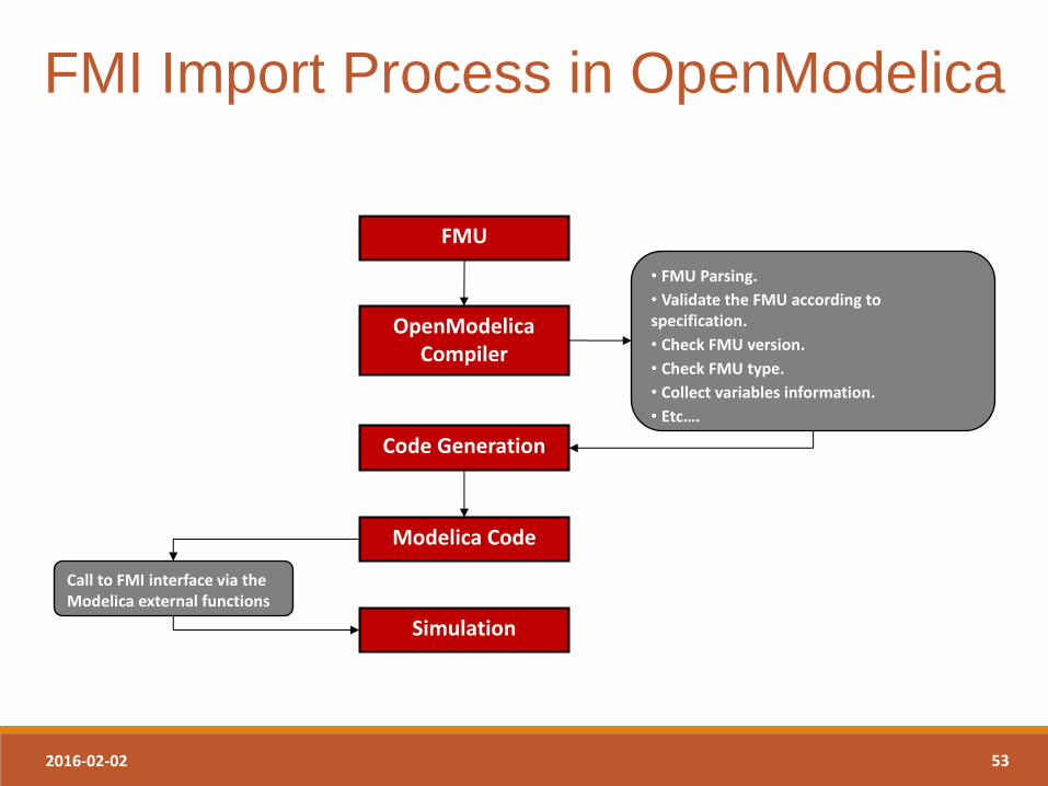
FMI Import Process in OpenModelica
FMU
OpenModelica Compiler
Code Generation
Modelica Code
• FMU Parsing.
• Validate the FMU according to specification.
• Check FMU version.
• Check FMU type.
• Collect variables information.
• Etc….
Simulation
Call to FMI interface via the Modelica external functions
2016-02-02 54
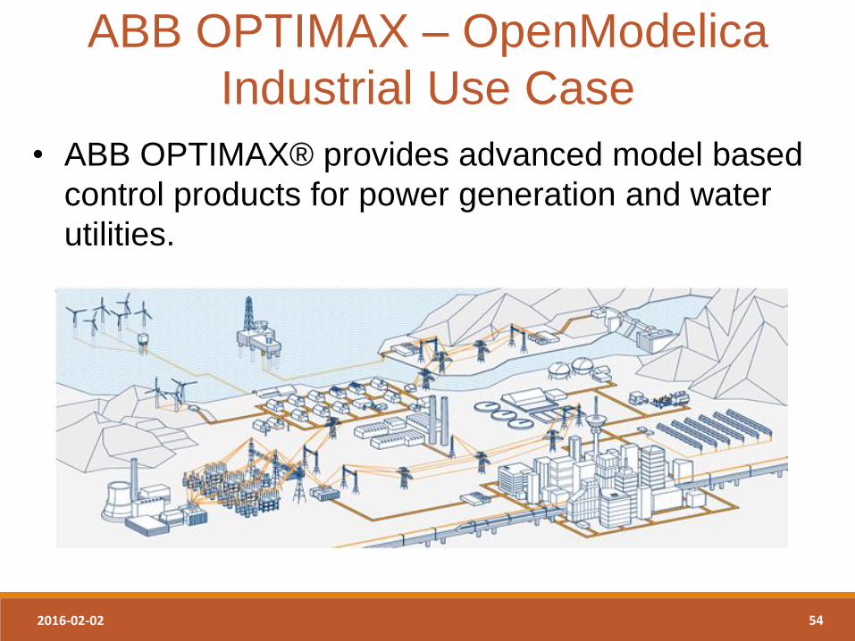
• ABB OPTIMAX® provides advanced model based
control products for power generation and water
utilities.
ABB OPTIMAX – OpenModelica
Industrial Use Case
2016-02-02 55
• Model-based optimization of power plants using
OpenModelica FMI 2.0.
• Plant models are formulated in Modelica and
deployed through FMI 2.0
• Link : http://new.abb.com/power-generation/power-
plant-optimization
ABB OPTIMAX – OpenModelica
Industrial Use Case