Embed Size (px)
Citation preview

OUR PLEDGE TO YOU:
When you buy Webster products, you buytotal service. Webster is the unique, single-source supplier of an extensive line of heat-ing products. We manufacture fuel units,supply and transfer pumps, valves and oilheat accessories. And we constantly seekbetter solutions and set higher standards forthe oil heat industry.
Webster is committed to reliable servicing ofits products. As always, our field servicepeople provide professional schooling andmake training materials and demonstrationunits available for training.
We are ready to work with you to help solve your specific heating problems.
An ISO 9001:2008 Company
Webster®
Fuel Pumps & ValvesA Division of Capital City Tool, Inc.
h126818 Capital City Tools_LN6331 4/26/16 10:21 AM Page 1
This Webster® Service Technician’s Handbook issupplied as a service to our customers, dealers andinstallers. It represents our efforts to share with themour experiences of many years with our productsin the field, and to also provide condensed cataloginformation to you on Webster products.
This booklet is not intended to be all-inclusive, orto be directly applicable to products manufacturedby any other company.
It remains the complete responsibility of all partiesinvolved in the design and installation of any systeminvolving Webster products to insure that thedesign and installation of the system is correct forthe individual circumstances, and that the systemis installed in compliance with all applicable codes,standards, regulations or other restrictions.
Neither Webster, nor any of its authorized repre-sentatives, assume any responsibility, obligationor liability relating to the design and/or installationof any systems utilizing Webster component parts,and nothing contained in this Service Technician’sHandbook should be construed as constitutingany extension of its standard Warranty Policy asstated in this booklet.
Webster®
Fuel Pumps & Valves
h126818 Capital City Tools_LN6331 4/26/16 10:21 AM Page 2
i
Warranty Policy
Webster warrants that Products shall be free from defects inmaterials and workmanship for a period of two (2) years fromthe date of manufacture or one (1) year from the date of instal-lation, whichever period expires first. Webster will rebuild orreplace, at its option, all Products proven to its satisfaction to bedefective within such warranty period and returned to theWebster factory transportation charges prepaid. Webster’s soleobligation and buyer’s exclusive remedy hereunder is limited tosuch rebuilding or replacement.
No products may be returned to Webster unless the prior writ-ten consent for said return shall have been obtained from theCustomer Service Department in Frankfort, Kentucky. ThisLimited Warranty does not cover shipping costs to and from theWebster factory, any costs for labor or otherwise related toproduct removal or replacement, or any other costs of anynature without prior written consent by Webster.
Parts, products and accessories made by others are warrantedonly to the extent of the original manufacturer’s warranty toWebster.
This warranty shall not apply to acts of God, war or civil insur-rection, nor shall it apply to products which, in the sole judge-ment of Webster, have been subject to negligence, abuse, acci-dent, misapplication, tampering, alteration; nor due to otherthan normal application, use or service, including but not limitedto, operational failures caused by corrosion, rust or other foreignmaterials in the system, or operation at pressures in excess ofrecommended maximums.
Purchaser shall be solely responsible for determining suitabilityfor use of Webster Products. Webster shall not in any eventwhatsoever, have any liability with respect to such determination.
THE FOREGOING WARRANTY IS EXCLUSIVE AND INLIEU OF ALL OTHER WARRANTIES, EXPRESS ORIMPLIED, INCLUDING BUT NOT LIMITED TO THEIMPLIED WARRANTIES OF MERCHANTABILITY ANDFITNESS FOR A PARTICULAR PURPOSE. WEBSTERSHALL NOT BE LIABLE FOR ANY CONSEQUENTIAL,INCIDENTAL OR CONTINGENT DAMAGES WHATSOEVER.
NOTE TO CONSUMERS: THIS LIMITED WARRANTY ISEXTENDED TO THE COMMERCIAL CUSTOMERS,DEALERS AND INSTALLERS OF WEBSTER ONLY. THESUPPLIER / INSTALLER WILL EXTEND WARRANTYCOVERAGE TO YOU WHICH COVERS WEBSTER’SPRODUCTS. WEBSTER’S WARRANTY TO SUCH CUS-TOMERS, DEALERS AND INSTALLERS WILL BACK UPTHE WARRANTY EXTENDED TO THE CONSUMER.
h126818 Capital City Tools_LN6331 4/26/16 10:21 AM Page i

ii
fUEl UNITS . . . . . . . . . . . . . . . . . . . . . . . . . . . . . . . . 1General Information . . . . . . . . . . . . . . . . . . . . . . . 1
Oil Heating Terminology . . . . . . . . . . . . . . . . . . . 1How A Fuel Unit Works . . . . . . . . . . . . . . . . . . 1-2Basic System Installations . . . . . . . . . . . . . . . . 3-4Installation and Service Tips. . . . . . . . . . . . . . 5-12Service Call Checklist . . . . . . . . . . . . . . . . . 13-14
Metering Pump . . . . . . . . . . . . . . . . . . . . . . . . 14-15M Series fuel Units . . . . . . . . . . . . . . . . . . . . . . . 16
Single- and Two-Stage . . . . . . . . . . . . . . . . . . . 16M34DK-3 Series fuel Units . . . . . . . . . . . . . . . . 16
Single-Stage . . . . . . . . . . . . . . . . . . . . . . . . . . . 16Fuel Unit Specifications . . . . . . . . . . . . . . . . . . 17Code Analysis . . . . . . . . . . . . . . . . . . . . . . . . . . 18Selection Tables and Dimensions . . . . . . . . . . . 19Fuel Unit Cross Reference . . . . . . . . . . . . . 19-20Installation Data . . . . . . . . . . . . . . . . . . . . . . 21-25
bIO Pump. . . . . . . . . . . . . . . . . . . . . . . . . . . . . 26-29Waste Oil Pumps. . . . . . . . . . . . . . . . . . . . . . . 30-33R Series Service Saver fuel Units . . . . . . . . . . . 34
Fuel Unit Specifications . . . . . . . . . . . . . . . . . . 34Selection Table—Single-Stage . . . . . . . . . . 35-37Selection Table—Two-Stage . . . . . . . . . . . . 38-40R Series Code Analysis . . . . . . . . . . . . . . . . . . 41Fuel Unit Cross Reference . . . . . . . . . . . . . 41-42Installation Data . . . . . . . . . . . . . . . . . . . . . . 43-50
1 R00 Series Single-Stage Transfer Pumps . . . 51 Fuel Unit Specifications . . . . . . . . . . . . . . . . . . . 51Selection Table . . . . . . . . . . . . . . . . . . . . . . . . . 52R Series Fuel Unit Code Analysis . . . . . . . . . . . 52Installation Data . . . . . . . . . . . . . . . . . . . . . . 53-54
V Series High Delivery fuel Pumps . . . . . . . . . . 55Fuel Unit Specifications . . . . . . . . . . . . . . . . . . . 56Selection Table . . . . . . . . . . . . . . . . . . . . . . . 57-58V Series Code Analysis . . . . . . . . . . . . . . . . . . . 59Installation Data . . . . . . . . . . . . . . . . . . . . . . 60-62
b Series fuel Oil Transfer Pumps . . . . . . . . . . . 63Fuel Unit Specifications . . . . . . . . . . . . . . . . 63-64Selection Table. . . . . . . . . . . . . . . . . . . . . . . . . . 64Typical Performance Curves. . . . . . . . . . . . . 65-66Installation Data . . . . . . . . . . . . . . . . . . . . . . . . . 67
SUPPlY PUMP UNITS. . . . . . . . . . . . . . . . . . . . . 68-69General Information . . . . . . . . . . . . . . . . . . . . . . . 70SPM Series Supply Units . . . . . . . . . . . . . . . . . . 71Duplex Pump Units—SPM Series . . . . . . . . . . . 72
Supply Unit Specifications . . . . . . . . . . . . . . . . 73Selection Tables . . . . . . . . . . . . . . . . . . . . . . 74-75Supply Unit Cross Reference . . . . . . . . . . . . . . 75Duplex Automatic General Info . . . . . . . . . . . 76-80Installation Data . . . . . . . . . . . . . . . . . . . . . . 81-84SPM Line Sizing . . . . . . . . . . . . . . . . . . . . . . . . 85Suction Line Sizing Charts . . . . . . . . . . . . . 86-89Discharge Line Sizing Charts . . . . . . . . . . . 90-97
TablE Of CONTENTS
h126818 Capital City Tools_LN6331 4/26/16 10:21 AM Page ii
iii
SPM Duplex Automatic Controls . . . . . . . . . . . . 98Electrical Connections . . . . . . . . . . . . . . . . . . . 99
SPMV SERIES . . . . . . . . . . . . . . . . . . . . . . . . . 100-101Fuel Unit Specifications . . . . . . . . . . . . . . . . . . 102SPMV Code Analysis and Selection Tables . . . . . . 103SPMV Flow Chart Dimensions . . . . . . . . . 104-106
PlC baSED DUPlEX aUTOMaTIC PUMP SETS . . . . . . . . . . . . . . . . . . . . . . . . 107-109Discharge Manifold Description and Set-Up . . . . 110Containment Basin . . . . . . . . . . . . . . . . . . . . . . . . 110
SPMb SERIES . . . . . . . . . . . . . . . . . . . . . . . . . . . . . 111Specifications . . . . . . . . . . . . . . . . . . . . . . . . . . 112SPMB Code Analysis . . . . . . . . . . . . . . . . 113-114SPMB Dimensions . . . . . . . . . . . . . . . . . . 115-116
TRaNSfER PUMP/MOTOR UNITS . . . . . . . . . . . . 117Specifications . . . . . . . . . . . . . . . . . . . . . . . . . . 117
35223 Series Transfer Units . . . . . . . . . . . . . . . 118Selection Table . . . . . . . . . . . . . . . . . . . . . . . . 118
35202 Series Transfer Units . . . . . . . . . . . . . . . 119Selection Table . . . . . . . . . . . . . . . . . . . . . 120-121
49116 Series Transfer Units . . . . . . . . . . . . . . . 122Selection Table. . . . . . . . . . . . . . . . . . . . . . . . . 122
fUEl UNIT aCCESSORIES . . . . . . . . . . . . . . . . . . 124Mounting accessories . . . . . . . . . . . . . . . . . . . . 124
Selection Table. . . . . . . . . . . . . . . . . . . . . . . . . 124Dimensions . . . . . . . . . . . . . . . . . . . . . . . . . . . 125
ValVES . . . . . . . . . . . . . . . . . . . . . . . . . . . . . . . . . . 126OSV® Oil Safety Valves . . . . . . . . . . . . . . . . . . . 126Operation . . . . . . . . . . . . . . . . . . . . . . . . . . . . . . 126
BIO-OSV Upgrade . . . . . . . . . . . . . . . . . . . . . . 126Section “a” . . . . . . . . . . . . . . . . . . . . . . . . . . . . 126
Installation . . . . . . . . . . . . . . . . . . . . . . . . . . . . 127Troubleshooting . . . . . . . . . . . . . . . . . . . . 127-128
Section “b” . . . . . . . . . . . . . . . . . . . . . . . . . . . . 128Installation. . . . . . . . . . . . . . . . . . . . . . . . . 128-129Open Loop System . . . . . . . . . . . . . . . . . . . . . 130General Considerations . . . . . . . . . . . . . . . . . . 130Porting Connections. . . . . . . . . . . . . . . . . . . . . 130Mounting . . . . . . . . . . . . . . . . . . . . . . . . . . . . . 130Filter . . . . . . . . . . . . . . . . . . . . . . . . . . . . . . . . . 130Priming . . . . . . . . . . . . . . . . . . . . . . . . . . . . . . . 130Check Local Codes . . . . . . . . . . . . . . . . . . . . . 130
Regulating Valves for Oil Heating . . . . . . . . . . 131RV Series . . . . . . . . . . . . . . . . . . . . . . . . . . . . . 131Specifications Dimensions . . . . . . . . . . . . 131-132Selection Table. . . . . . . . . . . . . . . . . . . . . . . . . 133Installation Data . . . . . . . . . . . . . . . . . . . . . . . . 134
Relief Valve . . . . . . . . . . . . . . . . . . . . . . . . . . . . . 135Vacuum breaker (48598) . . . . . . . . . . . . . . . . . . 136
Installation Data . . . . . . . . . . . . . . . . . . . . . . . . 136
TROUblESHOOTING General Pump Problems . . . . . . . . . . . . . 137-139
MaNUfaCTURER’S REPRESENTaTIVES. . . 140-141
h126818 Capital City Tools_LN6331 4/26/16 10:21 AM Page iii

1
fUEl UNITSGENERal INfORMaTIONOIl HEaTING TERMINOlOGYAs with most major industries, oil heating has devel-oped a language of its own which contains a number ofterms not encountered elsewhere The following listincludes the terms which are most common to the oilheating industry.
Single-stage fuel unit: unit with one set of gears for bothsuction and pressure.
Two-stage fuel unit: unit with two sets of gears, one forsuction and one for pressure.
One-pipe system: one line, an line, from tank to fuelunit.
Two-pipe system: two lines, one inlet and one returnline, from tank to fuel unit.
Bypass plug: small hex socket head pipe plug used toclose internal port and convert unit from one pipe to twopipe operation.
Bleed: to remove air from system.
Lift: oil drawn from a level below pump expressed in feetof lift or inches of mercury.
Head of oil: column of oil over fuel unit expressed in psior feet.
Inlet port: port which receives oil from tank.
Bypass port: port which discharges surplus oil back totank in two-pipe system.
Return line port: same as by-pass port.
Valve differential: number of pounds per square inch thepump pressure must drop from operating pressure toclose nozzle valve.
Delivery: gallons per hour pumped from the nozzle out-let assembly of the fuel unit.
Gear Set Capacity: Total amount of oil being displacedby the pumps gear set(s).
HOW a fUEl UNIT WORKS
The fuel unit performs three basic functions:
1. Supply the Oil. The pumping action,of the fuel unit isaccomplished by the gearset. In a single-stage fuel unitthere is only one set of gears. Their function is to drawoil from the tank and deliver the oil to the nozzle undersufficient pressure to ensure the oil is properly atomizedfor combustion. A single-stage fuel unit is generally
h126818 Capital City Tools_LN6331 4/26/16 10:21 AM Page 1

2
used where the fuel supply tank is above the burner orwhere the inlet vacuum is limited to 10” Hg or less whenmeasured at an unused inlet port.
A two-stage fuel unit has two sets of gears. The suctiongearset creates a vacuum within the fuel unit whichdraws oil from a submerged tank or a tank locatedbelow the oil burner and discharges it into an intermedi-ate chamber or reservoir which supplies the pressuregears. The pressure gearset delivers oil under pressureto the burner nozzle. Thus, the pressure gears do noneof the lifting.
2. Clean the Oil. Clean oil isessential for the efficientoperation of any oil burner.The purpose of the filter is toprotect the nozzle from for-eign particles or any othermatter that might clog theminute nozzle opening.Webster fuel units utilize ourexclusive rotary filter whichreduces the need for trouble-some periodic cleaning. Therotary filter’s blades rotate at motor speed with constantcleaning action to minimize clogging, compared tostrainer type filters. For maximum protection, an addi-tional line filter should be used, in accordance with rec-ommended standard practice.
3. build Pressure and Provide Clean fuel CutoffProbably the most important functions of the fuel unitare to build pressure to properly atomize the fuel oil andto provide clean cutoff of oil when the burner shutsdown. These functions are primarily performed by thevalve assembly consisting of a pressure regulatingspring, pressure adjusting screw, valve and valve seat,working in conjunction to the gearsets.
The pressure regulating spring and the pressure adjust-ing screw determine the pressure at which oil is deliv-ered to the nozzle. For example, when the spring in avalve assembly is set for 100 pounds per square inchpressure the valve will not open until the pressure gearshave built up enough pressure in the valve chamber toraise the piston from its seat. This prevents oil fromreaching the nozzle while under too low a pressure forcorrect atomization. The valve and valve seat controlthe flow of oil. They also are responsible for a sharpclean cutoff when the pressure within the fuel unit dropsbelow the setting of the valve spring. Webster’sM34DK-3 fuel unit has exceptionally fast fuel cutoffthrough the additional use of an internal flow controldevice.
h126818 Capital City Tools_LN6331 4/26/16 10:21 AM Page 2

3
baSIC SYSTEM INSTallaTIONS
There are two basic types of installation for fuel units:one-pipe systems or two-pipe systems.
The first of these, a one-pipe system, should not beconfused with a single-stage fuel unit. A one-pipe sys-tem can be installed employing either a single-stage ora two stage fuel unit. It is used where a gravity flow ofoil is available.
In a one pipe (single- or two-stage) system, the internalpumping capacity exceeds nozzle requirements. Theexcess flow is bypassed by the internal regulating valveand is recirculated within the pump. In the one-pipe con-nection, inlet line flow equals nozzle flow rate.
The second basic type is known as a two-pipe systemand should always be used wherever the oil supplylevel is below the fuel unit, whether it be a single or two-stage fuel unit.
On a two-pipe system there is a second pipe, called areturn line, between the fuel unit and the tank. Theexcess oil over and above that required by the nozzle isbypassed at the valve and returned to the tank.
A single-stage unit on a two-pipe system can be usedon lifts up to 10” HG. On the other hand, a two-stagewith a two-pipe system may be used on lifts up to 15” HG.
Existing Inside Tank Installation- One Pipe SystemTank above burner level
With the conventional one pipe gravity feed installationboth furnace and water heater can be operated off thesame suction line. Merely tee off the present line towater heater as shown in drawing below making sure oilsupply is above burner level at all times.
Existing Outside Tank Installation—Tank above burner level
The water heater may be added to the system by con-necting the suction line to the furnace suction line as
h126818 Capital City Tools_LN6331 4/26/16 10:21 AM Page 3

4
shown in drawing below. No return line is necessaryfrom the water heater as the system is flooded due tothe siphoning action when the tank is above burnerlevel.
Existing Outside Tank Installation —Tank below burner level
The water heater may be added to the system byinstalling a check valve in the suction line at both fuelunits as shown in drawing below. Both units must be setfor (2) two-pipe operation. This method should only beused when it’s impossible to add an independent suctionline to the water heater as shown in bottom drawing
New Outside Tank Installation —Tank below burner level
Individual suction lines should be used on all new instal-lations. Return lines may be manifolded as shown indrawing below.
h126818 Capital City Tools_LN6331 4/26/16 10:21 AM Page 4

5
INSTallaTION aND SERVICE TIPS
When installing and servicing oil heating fuel units, sev-eral key points including service tools, use of propertubing sizes, fuel supply cut-off, and possible causes ofseal failure should be understood.
Effective Gauge Use
There are valuable tools needed in servicing any fuelunit, the two most essential are the pressure gauge andthe vacuum gauge. It is factually known that if thesegauges were used consistently, 75% of the fuel unitssent in for repair would never need to be removed fromthe burners. With the correct use of these two gauges,it is possible to check vacuum, lift, air leaks, delivery,pressure and cut-off.
Vacuum Gauge
The vacuum gauge can determine the existence of airleaks in the suction line. For example, if checking a sys-tem in which the tank is buried below the burner leveland the oil passes through a line filter, the vacuumgauge must show a reading. If the gauge does not showa reading, an air leak is present.
NOTE: When installing fuel units, to assure compli-
ance with National Fire Protection Association’s
bulletin 31, “Installation of Oil Burning Equipment”,
fuel unit inlet pressures should not exceed 3 psig.
Vacuum Data
Before removing a fuel unit from an oil burner, a checkshould be made with vacuum and pressure gauges ifyou suspect fuel unit trouble.
The vacuum gauge should be applied to the inlet port(“IN”) opposite the inlet port being used, or inserted inthe inlet line with a “TEE”.
Pressure Gauge(100 psi Operating
Pressure)
Nozzle Line
Inlet Line
Vacuum Gauge(Optional Inlet Connection)
Return Line(When Used Two Pipe
h126818 Capital City Tools_LN6331 4/26/16 10:21 AM Page 5
6
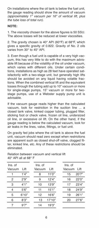
On installations where the oil tank is below the fuel unit,the gauge reading should show the amount of vacuum(approximately 1" vacuum per 16" of vertical lift, plusthe tube loss of total run).
NOTE:
1. The viscosity chosen for the above figures is 50 SSU.The above losses will be reduced at lower viscosities.
2. The gravity chosen is 40° API (60°F) at 68°F, whichgives a specific gravity of 0.822. Gravity of No. 2 oilsvaries from 30° to 45° API.
3. Even though a fuel unit is capable of a very high vac-uum, this has very little to do with the maximum advis-able lift because of the volatility of the oil under vacuum,which varies with different oils. Under certain condi-tions, installations as high as 28 feet have operated sat-isfactorily with a two-stage unit, but generally high liftsshould be avoided on any liquid having volatile frac-tions. When the combined vertical lift and the equivalentlosses through the tubing add up to 10” vacuum or morefor single-stage pumps, 15” vacuum or more for two-stage pumps, use of a Webster supply pump unit isadvisable.
If the vacuum gauge reads higher than the calculatedvacuum, look for restriction in the suction line ... aclosed tank valve, kinked copper tubing, plugged filter,sticking foot or check valve, frozen oil line, undersizedoil line, or excessive oil lift. On the other hand, if thegauge reading is below the calculated vacuum, look forair leaks in the lines, valve, fittings, or fuel unit.
On gravity fed jobs where the oil tank is above the fuelunit, vacuum should read zero except when restrictionsare apparent such as closed shut-off valve, clogged fil-ter, kinked line, etc. Any of these restrictions should beeliminated.
Relation between vacuum and vertical lift40° API all at 68° F
Ins. of Ins. of Ins. of
Vacuum Lift Vacuum Lift Vacuum Lift
1 1’4” 8 11’0” 15 20’7”
2 2’9” 9 12’4” 16 22’0”
3 4’1” 10 13’9” 17 23’4”
4 5’6” 11 15’1” 18 24’9”
5 6’10” 12 16’6” 19 26’1”
6 8’3” 13 17’10” 20 27’6”
7 9’7” 14 19’3”
h126818 Capital City Tools_LN6331 4/26/16 10:21 AM Page 6
7
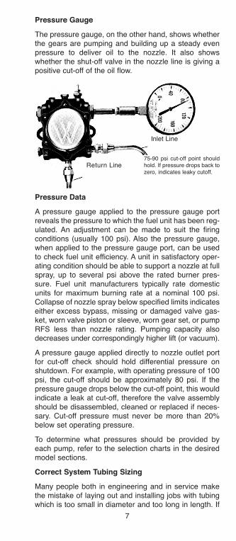
Pressure Gauge
The pressure gauge, on the other hand, shows whetherthe gears are pumping and building up a steady evenpressure to deliver oil to the nozzle. It also showswhether the shut-off valve in the nozzle line is giving apositive cut-off of the oil flow.
Pressure Data
A pressure gauge applied to the pressure gauge portreveals the pressure to which the fuel unit has been reg-ulated. An adjustment can be made to suit the firingconditions (usually 100 psi). Also the pressure gauge,when applied to the pressure gauge port, can be usedto check fuel unit efficiency. A unit in satisfactory oper-ating condition should be able to support a nozzle at fullspray, up to several psi above the rated burner pres-sure. Fuel unit manufacturers typically rate domesticunits for maximum burning rate at a nominal 100 psi.Collapse of nozzle spray below specified limits indicateseither excess bypass, missing or damaged valve gas-ket, worn valve piston or sleeve, worn gear set, or pumpRFS less than nozzle rating. Pumping capacity alsodecreases under correspondingly higher lift (or vacuum).
A pressure gauge applied directly to nozzle outlet portfor cut-off check should hold differential pressure onshutdown. For example, with operating pressure of 100psi, the cut-off should be approximately 80 psi. If thepressure gauge drops below the cut-off point, this wouldindicate a leak at cut-off, therefore the valve assemblyshould be disassembled, cleaned or replaced if neces-sary. Cut-off pressure must never be more than 20%below set operating pressure.
To determine what pressures should be provided byeach pump, refer to the selection charts in the desiredmodel sections.
Correct System Tubing Sizing
Many people both in engineering and in service makethe mistake of laying out and installing jobs with tubingwhich is too small in diameter and too long in length. If
Return Line
Inlet Line
75-90 psi cut-off point shouldhold. If pressure drops back tozero, indicates leaky cutoff.
h126818 Capital City Tools_LN6331 4/26/16 10:21 AM Page 7

8
a fuel unit with a pumping capacity of not more than 30gallons per hour is used, tubing of 1/2” OD can be usedwith safety.
The tubing size can vary widely depending upon flowrate. See the pipe sizing charts for help in determiningwhich tubing size is best suited for each application.
To Determine Suction line Size in InstallationsUsing Webster fuel Units on Two-Pipe Systems
1. Check suction gear capacity (see table of pumps).
2. Measure total tube length (horizontal and vertical).
3. Refer to “Friction Tube Loss Chart” for desired tubingsize. Read up from line “total feet of copper tube” to“suction capacity” in gph.
4. Read left to column “inches of vacuum at fuel unit”.(This is vacuum required to draw oil through tube listedof given length.)
5. If installation has lift add .75” of vacuum for every footof lift.
Rule of Thumb:
A quick rule to check an installation is to figure 1”of vacuum for every foot of vertical lift, and 1” ofvacuum for every 10’ of horizontal run Refer toFrictional Tube Loss charts for actual installation data.
6. Total inches of vacuum (frictional tube loss plus lift ifany).
7. If total is over 10” when single stage is employed ontwo-pipe system, check on next larger tube size chartfor proper tube size.
8. If total is over 15” when two-stage unit is employedon a two-pipe system, check on next larger tube sizechart.
9. The above does not allow for any added restrictionssuch as line filter, elbows, sharp bends, check valves, etc.
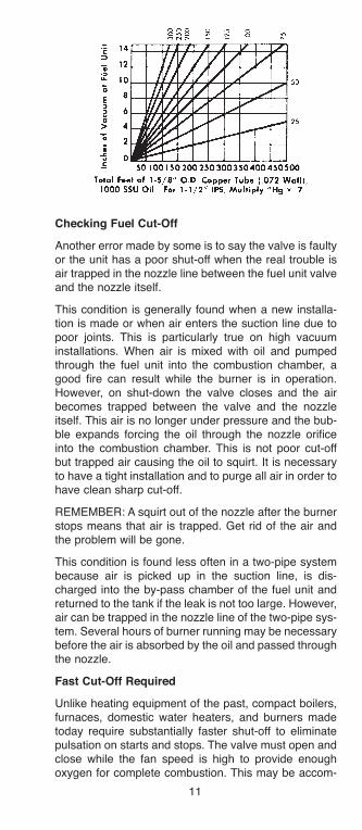
On high lifts and long runs, too small tubing will causethe oil to separate and have a milky appearance. This isnot air, it is actually light, volatile portion of the oil sepa-rating from the heavy portion. This is likely to occur anytime the vacuum gauge shows a reading of 15” or more,and may occur at a lower vacuum with some oils. Whenvacuums of 20” to 22” are reached, the pressure gaugewill start to bounce and delivery at the nozzle will beginto fall off. To correct these conditions, check the tubing.If the tubing size is correct and there are no kinks orother restrictions, a supply or booster pump may be
h126818 Capital City Tools_LN6331 4/26/16 10:21 AM Page 8
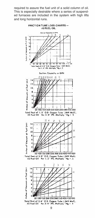
9
required to assure the fuel unit of a solid column of oil.This is especially desirable where a series of suspend-ed furnaces are included in the system with high lifts
and long horizontal runs.
h126818 Capital City Tools_LN6331 4/26/16 10:21 AM Page 9
10
h126818 Capital City Tools_LN6331 4/26/16 10:21 AM Page 10
11
Checking fuel Cut-Off
Another error made by some is to say the valve is faultyor the unit has a poor shut-off when the real trouble isair trapped in the nozzle line between the fuel unit valveand the nozzle itself.
This condition is generally found when a new installa-tion is made or when air enters the suction line due topoor joints. This is particularly true on high vacuuminstallations. When air is mixed with oil and pumpedthrough the fuel unit into the combustion chamber, agood fire can result while the burner is in operation.However, on shut-down the valve closes and the airbecomes trapped between the valve and the nozzleitself. This air is no longer under pressure and the bub-ble expands forcing the oil through the nozzle orificeinto the combustion chamber. This is not poor cut-offbut trapped air causing the oil to squirt. It is necessaryto have a tight installation and to purge all air in order tohave clean sharp cut-off.
REMEMBER: A squirt out of the nozzle after the burnerstops means that air is trapped. Get rid of the air andthe problem will be gone.
This condition is found less often in a two-pipe systembecause air is picked up in the suction line, is dis-charged into the by-pass chamber of the fuel unit andreturned to the tank if the leak is not too large. However,air can be trapped in the nozzle line of the two-pipe sys-tem. Several hours of burner running may be necessarybefore the air is absorbed by the oil and passed throughthe nozzle.
fast Cut-Off Required
Unlike heating equipment of the past, compact boilers,furnaces, domestic water heaters, and burners madetoday require substantially faster shut-off to eliminatepulsation on starts and stops. The valve must open andclose while the fan speed is high to provide enoughoxygen for complete combustion. This may be accom-
h126818 Capital City Tools_LN6331 4/26/16 10:21 AM Page 11
12
plished by using a solenoid valve which cuts off the flowof oil instantly on shut-down.
Since the use of a solenoid is often costly for someinstallations, Webster offers the M34DK-3 as a fastshut-off alternative. In this unit the valve opens andcloses at approximately 2,400 rpm fan speed. At thisspeed the air pattern is well established, both in thetube and in the chamber, and the burner operates with-out a smoke plume, eliminating pulsation on starts andstops. The volume of air delivered by the fan at such aspeed provides the oxygen necessary for completecombustion insuring clean, quiet operation when theburner is set at maximum efficiency.
Checking Seal leaks
Seal leaks generally do not occur; they are caused. Itmust be remembered that a seal can be operated underconditions ranging from high vacuum to pressure (psi).Where there is a head of oil over the fuel unit, a pres-sure gauge can be installed in the suction port of theunit to check head pressure. If the head pressure isover 3 psi an oil safety valve (OSV) should be installedin the suction line between the oil tank and the unit.
This also holds true where there are pressurized linesleading to the fuel unit, such as a series of suspendedfurnaces being served by a supply pump.
REMEMBER: To comply with NFPA standards, fuel unitinlet pressures must be limited to 3 psi.
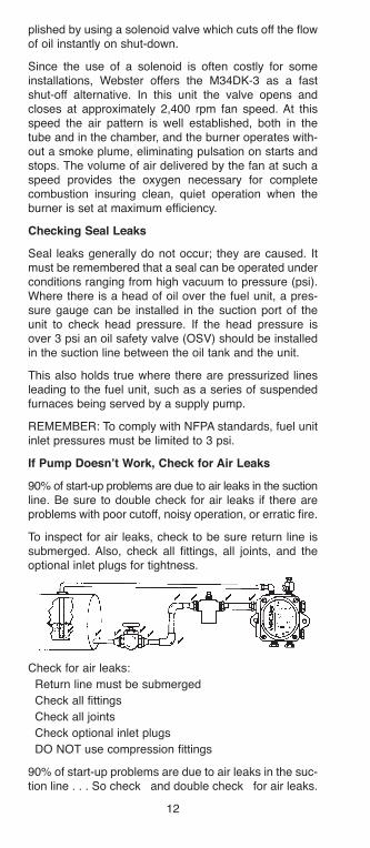
If Pump Doesn’t Work, Check for air leaks
90% of start-up problems are due to air leaks in the suctionline. Be sure to double check for air leaks if there areproblems with poor cutoff, noisy operation, or erratic fire.
To inspect for air leaks, check to be sure return line issubmerged. Also, check all fittings, all joints, and theoptional inlet plugs for tightness.
Check for air leaks:
� Return line must be submerged
� Check all fittings
� Check all joints
� Check optional inlet plugs
� DO NOT use compression fittings
90% of start-up problems are due to air leaks in the suc-tion line . . . So check � and double check � for air leaks.
h126818 Capital City Tools_LN6331 4/26/16 10:21 AM Page 12
13
filter Use
Both the Webster M and R Series contain an internalrotary filter. In addition to this filter, it is recommendedthat an external filter be used. The self cleaning rotaryfilter is designed to prolong fuel unit life and reduce fuelunit maintenance. It is not intended to be a replacementfor the external filter.
IMPORTaNT: Use of non-hardening oil pipe dope isrecommended on threads of all fittings. Do not loosen ortry to tighten any pump plugs not to be used in theinstallation. Do not use Teflon Tape. Evidence of teflontape use will be cause to void all warranties.
SERVICE Call CHECKlIST
The following procedure has been established to helpsave on service time and needless work when checkinga “no heat” service call. This procedure is intended to beused by qualified heating service technicians only.
1. Check the thermostat to make sure that corrosion,dust or other foreign matter are not causing faulty con-tact and switches are properly set.
2. Check both the main fuses and the oil burner circuitfuses. Replace if required.
3. Check the oil supply and the shut-off valve in the oilline. Adequate oil and open valve are required.
4. Open the door of the heating plant and see if there israw oil on the walls of the combustion chamber
5. Leave the inspection door open and press the burneroil reset button.
6. Check the oil burner controls in accordance with theoil burner manufacturer’s instructions.
7. If at any point on the foregoing checks the burneroperates, observe it for two or three complete cycles todetermine whether the stoppage may occur.
8. If the burner does not operate, check to see if motor,fan and pump shaft are all rotating.
9. If there is oil spray but no ignition, check all electricalconnections and the transformer.
10. If the electrical connections and transformer areoperating properly, remove the firing assembly andcheck the electrodes for coking, spading, and crackedporcelains.
11. While the firing assembly is out of the heating plant,clean or replace nozzle.
12. If no oil spray appears, check the line filter and thefuel unit, using vacuum and pressure gauges.
h126818 Capital City Tools_LN6331 4/26/16 10:21 AM Page 13

14
Vacuum gauge check usually covers the suction side ofthe system.
Pressure gauge determines efficiency of pumping gearsand valve. The valve can be serviced in the field. Wornpumping elements require the removal of the fuel unit.
Though these instructions may seem obvious, strictadherence to the sequence given can save valuableservice time when time is of importance.
METERING PUMP
MODEl # M17DN-M
Metering Pump for the air atomized waste oil burnermarket. Variable flow rates vs. RPM. Clockwise rotationlooking at shaft Viton seal. This unit is comparable tothe Suntec A2RA-7710 Pump.
h126818 Capital City Tools_LN6331 4/26/16 10:21 AM Page 14
15
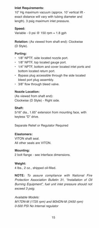
Inlet Requirements:
10” Hg maximum vacuum (approx. 10’ vertical lift -
exact distance will vary with tubing diameter and
length). 3 psig maximum inlet pressure.
Speed:
Variable - 0 psi @ 150 rpm = 1.8 gph
Rotation: (As viewed from shaft end): Clockwise
(D Style).
Porting:
• 1/8” NPTF, side located nozzle port.
• 1/8” NPTF, top located gauge port.
• 1/4” NPTF, bottom and cover located inlet ports and
bottom located return port.
• Bypass plug accessible through the side located
bleed port plug assembly.
• 3/8” flow through bleed valve.
Nozzle location:
(As viewed from shaft end):
Clockwise (D Style) - Right side.
Shaft:
5/16” dia., 1.65” extension from mounting face, with
keyless “D” drive.
Separate Relief or Regulator Required
Elastomers:
VITON shaft seal.
All other seals are VITON.
Mounting:
2 bolt flange - see interface dimensions.
Weight:
4 lbs., 2 oz., shipped oil-filled.
NOTE: To assure compliance with National Fire
Protection Association Bulletin 31, “Installation of Oil
Burning Equipment”, fuel unit inlet pressure should not
exceed 3 psig.
Available Models:
M17DN-M (1725 rpm) and M34DN-M (3450 rpm)
0-500 PSI No Internal regulator
h126818 Capital City Tools_LN6331 4/26/16 10:21 AM Page 15
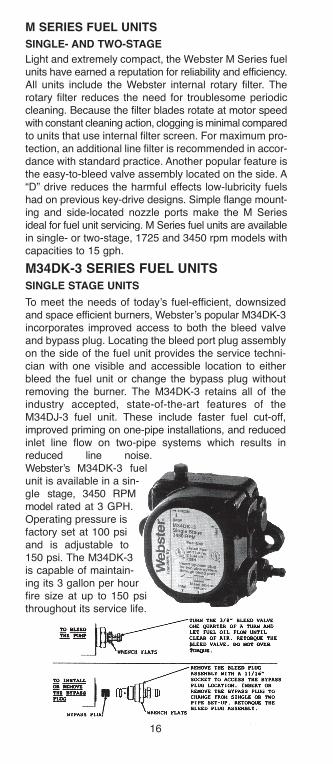
M34DK-3 SERIES fUEl UNITSSINGlE STaGE UNITS
To meet the needs of today’s fuel-efficient, downsizedand space efficient burners, Webster’s popular M34DK-3incorporates improved access to both the bleed valveand bypass plug. Locating the bleed port plug assemblyon the side of the fuel unit provides the service techni-cian with one visible and accessible location to eitherbleed the fuel unit or change the bypass plug withoutremoving the burner. The M34DK-3 retains all of theindustry accepted, state-of-the-art features of theM34DJ-3 fuel unit. These include faster fuel cut-off,improved priming on one-pipe installations, and reducedinlet line flow on two-pipe systems which results inreduced line noise.Webster’s M34DK-3 fuelunit is available in a sin-gle stage, 3450 RPMmodel rated at 3 GPH.Operating pressure isfactory set at 100 psiand is adjustable to150 psi. The M34DK-3is capable of maintain-ing its 3 gallon per hourfire size at up to 150 psithroughout its service life.
M SERIES fUEl UNITS
SINGlE- aND TWO-STaGE
Light and extremely compact, the Webster M Series fuelunits have earned a reputation for reliability and efficiency.All units include the Webster internal rotary filter. Therotary filter reduces the need for troublesome periodiccleaning. Because the filter blades rotate at motor speedwith constant cleaning action, clogging is minimal comparedto units that use internal filter screen. For maximum pro-tection, an additional line filter is recommended in accor-dance with standard practice. Another popular feature isthe easy-to-bleed valve assembly located on the side. A“D” drive reduces the harmful effects low-lubricity fuelshad on previous key-drive designs. Simple flange mount-ing and side-located nozzle ports make the M Seriesideal for fuel unit servicing. M Series fuel units are availablein single- or two-stage, 1725 and 3450 rpm models withcapacities to 15 gph.
16
h126818 Capital City Tools_LN6331 4/26/16 10:23 AM Page 16
17
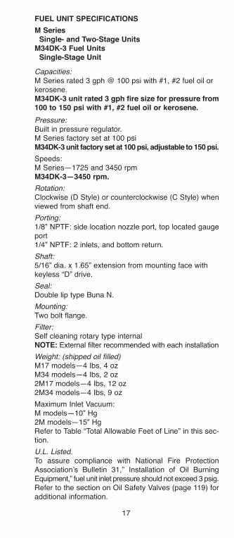
fUEl UNIT SPECIfICaTIONS
M SeriesSingle- and Two-Stage Units
M34DK-3 fuel UnitsSingle-Stage Unit
Capacities:M Series rated 3 gph @ 100 psi with #1, #2 fuel oil orkerosene.M34DK-3 unit rated 3 gph fire size for pressure from100 to 150 psi with #1, #2 fuel oil or kerosene.
Pressure:Built in pressure regulator.M Series factory set at 100 psiM34DK-3 unit factory set at 100 psi, adjustable to 150 psi.
Speeds: M Series—1725 and 3450 rpm M34DK-3—3450 rpm.
Rotation: Clockwise (D Style) or counterclockwise (C Style) whenviewed from shaft end.
Porting:1/8” NPTF: side location nozzle port, top located gaugeport1/4” NPTF: 2 inlets, and bottom return.
Shaft:5/16” dia. x 1.65” extension from mounting face withkeyless “D” drive.
Seal: Double lip type Buna N.
Mounting: Two bolt flange.
Filter: Self cleaning rotary type internal NOTE: External filter recommended with each installation
Weight: (shipped oil filled)M17 models—4 Ibs, 4 ozM34 models—4 Ibs, 2 oz2M17 models—4 Ibs, 12 oz2M34 models—4 Ibs, 9 oz
Maximum Inlet Vacuum: M models—10” Hg 2M models—15” Hg Refer to Table “Total Allowable Feet of Line” in this sec-tion.
U.L. Listed.To assure compliance with National Fire ProtectionAssociation’s Bulletin 31,” Installation of Oil BurningEquipment,” fuel unit inlet pressure should not exceed 3 psig.Refer to the section on Oil Safety Valves (page 119) foradditional information.
h126818 Capital City Tools_LN6331 4/26/16 10:23 AM Page 17

18
M-SERIES fUEl UNIT-CODE aNalYSIS
A— M = Single Stage2M= Two Stage
B— 17 = 1725 RPM34 = 3450 RPM
C— C = CCW rotation, outlet leftD = CW rotation, outlet right
(as viewed from shaft end)
D— A = Key drive, face seal, old style portingB = Std., face seal, old style portingC = Special, face seal, old style portingD = Std. lip seal, old style portingE = Special, lip seal, old style portingF = Same as D except revised portingG = Same as E except revised portingH = Same as F except o-ring on pressure
adjusting screwJ = Same as H except revised internal portingK = Same as J except revised porting and bleed
valve locationL = Same as K except revised porting and
bleed valve locationM = BIO PumpN = Waste Oil Pump
E— 3 = 3gph max. recommended fire size6 = 6gph max. recommended fire size15 = 15gph max. recommended fire sizeM = Metering Pump
F— No *=unit set 1 pipe(bypass plug not installed)
*=Unit set 2 pipe(bypass plug installed)
h126818 Capital City Tools_LN6331 4/26/16 10:23 AM Page 18
19
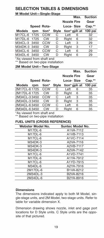
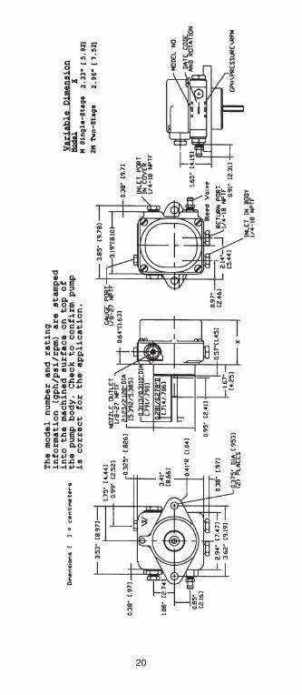
dimensions
The dimensions indicated apply to both M Model, sin-gle-stage units, and 2M Model, two-stage units. Refer totable for variable dimension X.
Dimension drawing shows nozzle, inlet and gage portlocations for D Style units. C Style units are the oppo-site of that pictured.
m model Unit—single-stagemax. suction
Nozzle Fire Gear
speed Rota- loca- size cap.**
models rpm tion* style tion* gph at 100 psi
M17CL-6 1725 CCW C Lett 6 32M17DL-6 1725 CW D Right 6 32M34CL-3 3450 CCW C Left 3 29M34DK-3 3450 CW D Right 3 17M34CL-6 3450 CCW C Left 6 29M34DL-6 3450 CW D Right 6 29*As viewed from shaft end** Based on two-pipe installation
2m model Unit—Two-stage
max. suction
Nozzle Fire Gear
speed Rota- loca- size cap.**
models rpm tion* style tion* gph at 100 psi
2M17CL-6 1725 CCW C Left 6 352M17DL-6 1725 CW D Right 6 352M34CL-3 3450 CCW C Left 3 352M34DL-3 3450 CW D Right 3 352M34CL-6 3450 CCW C Left 6 352M34DL-6 3450 CW D Right 6 35*As viewed from shaft end** Based on two-pipe installation
FUEl UNITs (cROss REFERENcE)
Webster model No. suntec model No.
M17DL-6 A1VA-7112M17DL-6 A1VB-7113M17CL-6 A1VC-7114M34DK-3 A2VA-7116M34DK-3 A2VB-7117M34DK-3 A2VA-7142M17CL-6 A1VD-7741M17DL-6 A1YA-7912M17CL-6 A1YD-7915M34DL-6 A2YA-79162M17DL-6 B1VA-82122M34DL-3 B2VA-82162M34DL-6 B2YA-8916
sElEcTION TABlEs & dImENsIONs
h126818 Capital City Tools_LN6331 4/26/16 10:23 AM Page 19
20
h126818 Capital City Tools_LN6331 4/26/16 10:23 AM Page 20
21
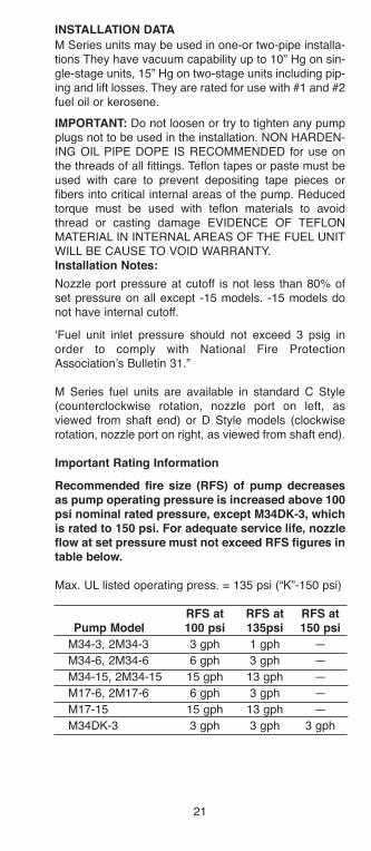
INSTallaTION DaTa
M Series units may be used in one-or two-pipe installa-tions They have vacuum capability up to 10” Hg on sin-gle-stage units, 15” Hg on two-stage units including pip-ing and lift losses. They are rated for use with #1 and #2fuel oil or kerosene.
IMPORTaNT: Do not loosen or try to tighten any pumpplugs not to be used in the installation. NON HARDEN-ING OIL PIPE DOPE IS RECOMMENDED for use onthe threads of all fittings. Teflon tapes or paste must beused with care to prevent depositing tape pieces orfibers into critical internal areas of the pump. Reducedtorque must be used with teflon materials to avoidthread or casting damage EVIDENCE OF TEFLONMATERIAL IN INTERNAL AREAS OF THE FUEL UNITWILL BE CAUSE TO VOID WARRANTY.Installation Notes:
Nozzle port pressure at cutoff is not less than 80% ofset pressure on all except -15 models. -15 models donot have internal cutoff.
‘Fuel unit inlet pressure should not exceed 3 psig inorder to comply with National Fire ProtectionAssociation’s Bulletin 31.”
M Series fuel units are available in standard C Style(counterclockwise rotation, nozzle port on left, asviewed from shaft end) or D Style models (clockwiserotation, nozzle port on right, as viewed from shaft end).
Important Rating Information
Recommended fire size (RfS) of pump decreasesas pump operating pressure is increased above 100psi nominal rated pressure, except M34DK-3, whichis rated to 150 psi. for adequate service life, nozzleflow at set pressure must not exceed RfS figures intable below.
Max. UL listed operating press. = 135 psi (“K”-150 psi)
RfS at RfS at RfS atPump Model 100 psi 135psi 150 psi
M34-3, 2M34-3 3 gph 1 gph —
M34-6, 2M34-6 6 gph 3 gph —
M34-15, 2M34-15 15 gph 13 gph —
M17-6, 2M17-6 6 gph 3 gph —
M17-15 15 gph 13 gph —
M34DK-3 3 gph 3 gph 3 gph
h126818 Capital City Tools_LN6331 4/26/16 10:23 AM Page 21

22
P/N
29533-2
1
h126818 Capital City Tools_LN6331 4/26/16 10:23 AM Page 22
23
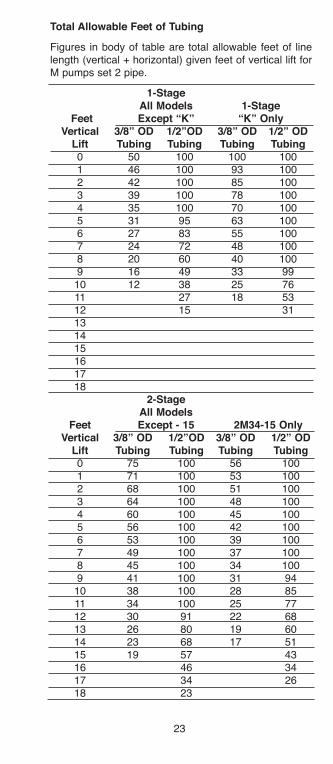
Total allowable feet of Tubing
Figures in body of table are total allowable feet of linelength (vertical + horizontal) given feet of vertical lift forM pumps set 2 pipe.
1-Stageall Models 1-Stage
feet Except “K” “K” OnlyVertical 3/8” OD 1/2”OD 3/8” OD 1/2” OD
lift Tubing Tubing Tubing Tubing0 50 100 100 1001 46 100 93 1002 42 100 85 1003 39 100 78 1004 35 100 70 1005 31 95 63 1006 27 83 55 1007 24 72 48 1008 20 60 40 1009 16 49 33 9910 12 38 25 7611 27 18 5312 15 31131415161718
2-Stageall Models
feet Except - 15 2M34-15 OnlyVertical 3/8” OD 1/2”OD 3/8” OD 1/2” OD
lift Tubing Tubing Tubing Tubing0 75 100 56 1001 71 100 53 1002 68 100 51 1003 64 100 48 1004 60 100 45 1005 56 100 42 1006 53 100 39 1007 49 100 37 1008 45 100 34 1009 41 100 31 94
10 38 100 28 8511 34 100 25 7712 30 91 22 6813 26 80 19 6014 23 68 17 5115 19 57 4316 46 3417 34 2618 23
h126818 Capital City Tools_LN6331 4/26/16 10:23 AM Page 23
24
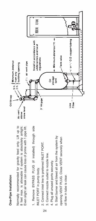
On
e-P
ipe I
nsta
llati
on
Norm
ally
re
com
mended fo
r gra
vity fe
ed only
. Lift
up to
8 fe
et
max.
is allo
wable
if syste
m is
absolu
tely
airtight.
Even s
light
air leak c
an c
ause loss o
f prim
e w
ith 1
pip
e lift.
1.
Rem
ove
BY
PA
SS
P
LU
G
(if
insta
lled)
thro
ugh
sid
e
INLE
T P
OR
T in p
um
p b
ody.
2.
Connect
inle
t lin
e t
o p
refe
rred I
NLE
T P
OR
T.
3.
Connect
nozzle
outlet
to n
ozzle
lin
e.
4.
Plu
g a
ll unused p
ort
s s
ecure
ly.
5.
Sta
rt b
urn
er
and b
leed a
ll air f
rom
the s
yste
m b
y
openin
g V
EN
T P
LU
G.
Clo
se V
EN
T s
ecure
ly w
hen
oil
flow
in t
ube is c
lear.
h126818 Capital City Tools_LN6331 4/26/16 10:23 AM Page 24
25
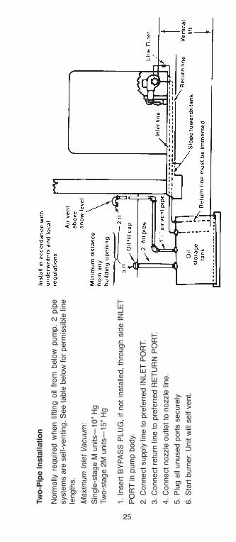
Tw
o-P
ipe I
nsta
llati
on
Norm
ally
required w
hen l
ifting o
il fr
om
belo
w p
um
p.
2 p
ipe
syste
ms a
re s
elf-v
enting.
See t
able
belo
w f
or
perm
issib
le lin
ele
ngth
s.
Maxim
um
Inle
t V
acuum
:
Sin
gle
-sta
ge M
units—
10”
Hg
Tw
o-s
tage 2
M u
nits—
15”
Hg
1.
Insert
BY
PA
SS
PLU
G,
if n
ot
insta
lled,
thro
ugh s
ide I
NLE
T
PO
RT
in p
um
p b
ody.
2.
Connect
supply
lin
e t
o p
refe
rred I
NLE
T P
OR
T.
3.
Connect
retu
rn lin
e t
o p
refe
rred R
ET
UR
N P
OR
T.
4.
Connect
nozzle
outlet
to n
ozzle
lin
e.
5.
Plu
g a
ll unused p
ort
s s
ecure
ly
6.
Sta
rt b
urn
er. U
nit w
ill s
elf v
ent.
h126818 Capital City Tools_LN6331 4/26/16 10:23 AM Page 25
featuresTo meet the needs of today’sfuel-efficient, downsized andspace efficient burners,Webster’s M34DM-3 incorpo-rates improved access to boththe bleed valve and bypassplug. Locating the bleed port plug assembly on the sideof the fuel unit provides the service technician with onevisible and accessible location to either bleed the fuelunit or change the bypass plug without removing the burner.
In addition to improved access the M34DM-3 cleanerblade has been thickened to provide a more robustcleaning action. For maximum protection, an additionalline filter should be used in accordance with recom-mended standard practice All of the BUNA-N elastomershave been replaced with VITON to provide extended lifeat critical locations within the fuel unit.
The M34DM-3 retains all the industry accepted, state-of-the-art features of the M34DK-3 fuel unit. These includefaster fuel cut-off, improved priming on single pipe instal-lations. This unit can easily replace your standard M34Dor A2VA residential pump.
The M34DM-3 is capable of maintaining a three gallonper hour fire size at up to 150 PSI throughout its designlife. The M34DM-3 is factory preset to 100 PSI and isadjustable to 150 PSI.
General Operation and fuel Unit Oil flowThe compact M34DM-3 Fuel Unit is engineered for effi-cient pumping of Bio fuel. The cut-away view illustratesthe oil flow through an M34DM-3 operating in a one pipesystem, with a suction line and no return to the storagetank.
A one pipe system is frequently used when the storagetank is located above the fuel unit, or when automaticventing is not necessary. Vacuum at the pump inletshould not exceed 10” Hg. For this type of installation tobe reliable, the total system must be completely airtight.During installation or servicing of the fuel unit, air may bemanually bled from the system through the side-locatedbleed valve.
The M34DM-3 will provide up to 10” Hg of inlet vacuum.The two pipe system (shown below), with both a suctionand return line is self-venting. This allows any air in thesystem to escape and be returned to the storage tankthrough the return line.
M34DM-3 Bio Pump
26
h126818 Capital City Tools_LN6331 4/26/16 10:23 AM Page 26
27
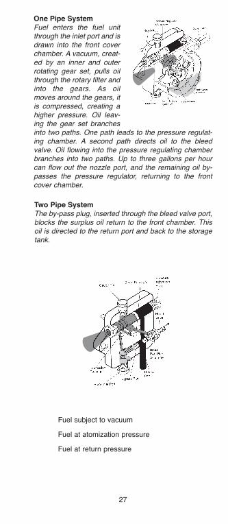
One Pipe SystemFuel enters the fuel unitthrough the inlet port and isdrawn into the front coverchamber. A vacuum, creat-ed by an inner and outerrotating gear set, pulls oilthrough the rotary filter andinto the gears. As oilmoves around the gears, itis compressed, creating ahigher pressure. Oil leav-ing the gear set branchesinto two paths. One path leads to the pressure regulat-ing chamber. A second path directs oil to the bleedvalve. Oil flowing into the pressure regulating chamberbranches into two paths. Up to three gallons per hourcan flow out the nozzle port, and the remaining oil by-passes the pressure regulator, returning to the frontcover chamber.
� Fuel subject to vacuum
� Fuel at atomization pressure
� Fuel at return pressure
Two Pipe SystemThe by-pass plug, inserted through the bleed valve port,blocks the surplus oil return to the front chamber. Thisoil is directed to the return port and back to the storagetank.
h126818 Capital City Tools_LN6331 4/26/16 10:23 AM Page 27

28
Specifications
firing Capacity:
Recommended to 3 GPH fire size for pressures from
100 to 150 PSI with #1, #2 fuel oil, Kerosene, or
Bio Fuel B100-B5 Bio Diesel
Gear Capacity:
25 GPH @ 100-150 PSI with #1, #2 fuel oil, Kerosene,
or Bio Fuel. B100-B5 Bio Diesel.
Pressure:
Factory set at 100 PSI.
Adjustable to 150 PSI.
Inlet Requirements:
10” Hg maximum vacuum (approx. 10’ vertical lift -
exact distance will vary with tubing diameter and
length). 3 psig maximum inlet pressure.
Speed:
3450 RPM.
Rotation: (As viewed from shaft end): Clockwise
(D Style).
Porting:
• 1/8” NPTF, side located nozzle port.
• 1/8” NPTF, top located gauge port.
• 1/4” NPTF, bottom and cover located inlet ports and
bottom located return port.
• Bypass plug accessible through the side located
bleed port plug assembly.
• 3/8” flow through bleed valve.
Nozzle location:
(As viewed from shaft end):
Clockwise (D Style) - Right side.
Shaft:
5/16” dia., 1.65” extension from mounting face, with
keyless “D” drive.
filter:
Self-cleaning rotary type.
Elastomers:
VITON shaft seal.
All other seals are VITON.
Mounting:
2 bolt flange - see interface dimensions.
h126818 Capital City Tools_LN6331 4/26/16 10:23 AM Page 28

29
Dimensions Dimensions in inches, ( ) = cm
Weight:
4 lbs., 2 oz., shipped oil-filled.
NOTE: To assure compliance with National Fire
Protection Association Bulletin 31, “Installation of Oil
Burning Equipment”, fuel unit inlet pressure should not
exceed 3 psig.
h126818 Capital City Tools_LN6331 4/26/16 10:23 AM Page 29
30
Waste Oil Pumps
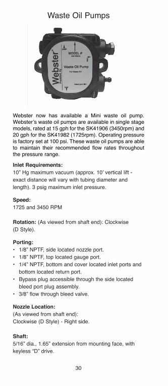
Webster now has available a Mini waste oil pump.Webster’s waste oil pumps are available in single stagemodels, rated at 15 gph for the SK41906 (3450rpm) and20 gph for the SK41982 (1725rpm). Operating pressureis factory set at 100 psi. These waste oil pumps are ableto maintain their recommended flow rates throughoutthe pressure range.
Inlet Requirements:
10” Hg maximum vacuum (approx. 10’ vertical lift -
exact distance will vary with tubing diameter and
length). 3 psig maximum inlet pressure.
Speed:
1725 and 3450 RPM
Rotation: (As viewed from shaft end): Clockwise
(D Style).
Porting:
• 1/8” NPTF, side located nozzle port.
• 1/8” NPTF, top located gauge port.
• 1/4” NPTF, bottom and cover located inlet ports and
bottom located return port.
• Bypass plug accessible through the side located
bleed port plug assembly.
• 3/8” flow through bleed valve.
Nozzle location:
(As viewed from shaft end):
Clockwise (D Style) - Right side.
Shaft:
5/16” dia., 1.65” extension from mounting face, with
keyless “D” drive.
h126818 Capital City Tools_LN6331 4/26/16 10:23 AM Page 30

31
Elastomers:
VITON shaft seal.
All other seals are VITON.
Mounting:
2 bolt flange - see interface dimensions.
Weight:
4 lbs., 2 oz., shipped oil-filled.
NOTE:
To assure compliance with National Fire Protection
Association Bulletin 31, “Installation of Oil Burning
Equipment”, fuel unit inlet pressure should not exceed
3 psig.
location from RfS Rated Gear SetSingle Stage Shaft End GPH PSI CapacityM17DN-15 CW/R 15 40 35M17DN-6 CW/R 6 40 35M34DN-3 CW/R 3 40 31M34DN-3H CW/R 3 150 31M34DN-15 CW/R 15 40 352M34DN-15-H CW/R 15 150 35SK41906R CW/R 14 100 27SK41982R CW/R 14 100 27
Dimensions: Dimensions In Inches, ( ) = cm
h126818 Capital City Tools_LN6331 4/26/16 10:23 AM Page 31
32
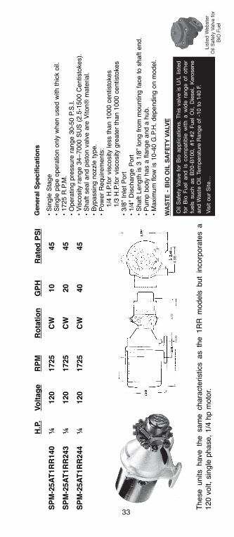
GENERAl sPEcIFIcATIONs• Single Stage• Single pipe operation only when used with thick
oil.• 1725 R.P.M.• Operating pressure range 30-50 P.S.I.• Viscosity range 34–7000 SUS (2.5-1500
Centistokes).• Shaft seal and piston valve are Viton® material.• Bypassing nozzle type.• Power Requirements:• 1/4 H.P. for viscosity less than 1000 centistokes• 1/3 H.P. for viscosity greater than 1000 centis-
tokes.• Shaft Length is 3 1/8” long from mounting face
to shaft end.• Pump body has a flange and a hub.• Maximum flow is 10-40 G.P.H. depending on
model.Rated
H.P. Voltage RPM Rotation GPH PSI
SPM-25aT1RR140 1/4 120 1725 CW 10 45
SPM-25aT1RR243 1/4 120 1725 CW 20 45
SPM-25aT1RR244 1/4 120 1725 CW 40 45
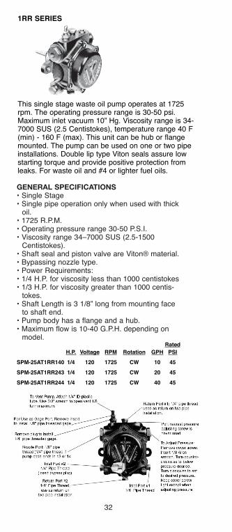
1RR SERIES
This single stage waste oil pump operates at 1725rpm. The operating pressure range is 30-50 psi.Maximum inlet vacuum 10” Hg. Viscosity range is 34-7000 SUS (2.5 Centistokes), temperature range 40 F(min) - 160 F (max). This unit can be hub or flangemounted. The pump can be used on one or two pipeinstallations. Double lip type Viton seals assure lowstarting torque and provide positive protection fromleaks. For waste oil and #4 or lighter fuel oils.
h126818 Capital City Tools_LN6331 4/26/16 10:23 AM Page 32
33
H.P
.V
olt
ag
eR
PM
Ro
tati
on
GP
HR
ate
d P
SI
SP
M-2
5a
T1R
R140
¼120
1725
CW
10
45
SP
M-2
5a
T1R
R243
¼120
1725
CW
20
45
SP
M-2
5a
T1R
R244
¼120
1725
CW
40
45
These u
nits h
ave t
he s
am
e c
hara
cte
ristics a
s t
he 1
RR
models
but
incorp
ora
tes a
120 v
olt,
sin
gle
phase,
1/4
hp m
oto
r.
Gen
era
l S
pecif
icati
on
s
• S
ingle
Sta
ge
• S
ingle
pip
e o
pera
tion o
nly
when u
sed w
ith t
hic
k o
il.•
1725 R
.P.M
.•
Opera
ting p
ressure
range 3
0-5
0 P
.S.I.
• V
iscosity r
ange 3
4–7000 S
US
(2.5
-1500 C
entisto
kes).
• S
haft s
eal and p
isto
n v
alv
e a
re V
iton®
mate
rial.
• B
ypassin
g n
ozzle
type.
• P
ow
er
Requirem
ents
: 1/4
H.P
.for
vis
cosity less t
han 1
000 c
entisto
kes
1/3
H.P
.for
vis
cosity g
reate
r th
an 1
000 c
entisto
kes
• 3/8
” In
let
Port
• 1/4
” D
ischarg
e P
ort
• S
haft L
ength
is 3
1/8
” lo
ng f
rom
mounting f
ace t
o s
haft e
nd.
• P
um
p b
ody h
as a
fla
nge a
nd a
hub.
• M
axim
um
flo
w is 1
0-4
0 G
.P.H
. dependin
g o
n m
odel.
14.4
4
4.7
24.8
8
WA
sT
E -
BIO
OIl
sA
FE
TY
VA
lV
E
Oil Safety Va
lve for Bio applications. Th
is valve is U/L listed
for Bio Fue
l an
d is co
mpatible w
ith a w
ide rang
e of other
fuels such
as B20
-B10
0, #1-#2
Fue
l Oil, D
iesel, Kerosen
ean
d W
aste Oil. Tem
perature Ran
ge of -10 to 140
F.
Visit ou
r Site…
Listed
Web
ster
Oil Safety Va
lve for
BiO Fue
l
h126818 Capital City Tools_LN6331 4/26/16 10:23 AM Page 33
34
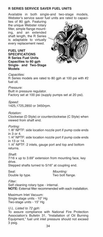
R SERIES SERVICE SaVER fUEl UNITS
Available in both single-and two-stage models,Webster’s service saver fuel units are rated to capaci-ties of 80 gph. Featuringthe unique Webster rotaryfilter, simple flange mount-ing, and an extendedshaft length, the R Seriesis adaptable to virtuallyevery replacement need.
fUEl UNITSPECIfICaTIONSR Series fuel UnitsCapacities to 80 gphSingle- and Two-StageModels
Capacities:R Series models are rated to 80 gph at 100 psi with #2fuel oil.
Pressure:Built in pressure regulator.Factory set at 100 psi (supply pumps set at 20 psi).
Speed:1425,1725,2850 or 3450rpm.
Rotation:Clockwise (D Style) or counterclockwise (C Style) whenviewed from shaft end.
Porting:1 /8” NPTF: side location nozzle port if pump code endsin 3 or 4.1 /4” NPTF: side location nozzle port if pump code endsin 13 or 14.1 /4” NPTF: 2 inlets, gauge port and top and bottomreturns.
Shaft:7/16 x up to 3.69” extension from mounting face, keydrive.Stepped shafts turned to 5/16” at coupling end.
Seal: Mounting:Double lip type. Two bolt flange.
Filter: Self cleaning rotary type - internal. NOTE: External filter recommended with each installation.
Maximum Inlet Vacuum:Single-stage units - 10” HgTwo-stage units - 15” Hg
U.L. Listed to 72 gph:To assure compliance with National Fire ProtectionAssociation’s Bulletin 31, “Installation of Oil BurningEquipment,” fuel unit inlet pressure should not exceed3 psig.
h126818 Capital City Tools_LN6331 4/26/16 10:23 AM Page 34

35
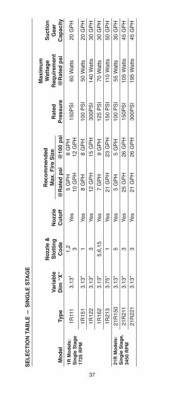
SE
lE
CT
ION
Ta
bl
E —
SIN
Gl
E S
Ta
GE
Maxim
um
No
zzle
&W
att
ag
eS
ucti
on
Vari
ab
leS
lott
ing
No
zzle
Rate
dR
eq
uir
em
en
tG
ear
Mo
del
Typ
eD
im “
X”
Co
de
Cu
toff
@R
ate
d p
si
@100 p
si
Pre
ssu
re@
Rate
d p
si
Cap
acit
y
1R
111
3.1
3”
1,2
Yes
5 G
PH
8 G
PH
150P
SI
60 W
atts
20 G
PH
310 G
PH
12 G
PH
1R
151
3.1
3”
1Y
es
8 G
PH
8 G
PH
100 P
SI
50 W
atts
20 G
PH
1R
122
3.1
3”
3Y
es
12 G
PH
15 G
PH
300P
SI
140 W
atts
30 G
PH
1R
162
3.1
3”
5,6
,15
Yes
7 G
PH
9 G
PH
125 P
SI
70 W
atts
30 G
PH
1R
213
3.7
5”
1Y
es
21 G
PH
23 G
PH
150 P
SI
110 W
atts
50 G
PH
21R
150
3.1
3”
5Y
es
5 G
PH
5 G
PH
100 P
SI
55 W
atts
30 G
PH
21R
211
3.1
3”
3Y
es
25 G
PH
26 G
PH
150P
SI
105 W
atts
45 G
PH
21R
221
3.1
3”
3Y
es
21 G
PH
26 G
PH
300P
SI
195 W
atts
45 G
PH
Reco
mm
en
ded
Max.
fir
e S
ize
1R
Mo
dels
:S
ing
le S
tag
e1725 R
PM
21R
Mo
dels
:S
ing
le S
tag
e,
3450 R
PM
h126818 Capital City Tools_LN6331 4/26/16 10:23 AM Page 35

36
31R
121
3.1
3”
4Y
es
4 G
PH
9 G
PH
300 P
SI
90 W
atts
20 G
PH
41R
221
3.1
3”
14
No
18 G
PH
22 G
PH
300P
SI
160 W
atts
40 G
PH
41R
221
3.1
3”
4Y
es
23 G
PH
28 G
PH
300P
SI
225 W
atts
55 G
PH
*To C
onvert
to h
ors
epow
er, m
ultip
ly w
atts X
.0013410
31R
Mo
dels
:S
ing
le S
tag
e1425 R
PM
41R
Mo
dels
:S
ing
le S
tag
e,
2850 R
PM
h126818 Capital City Tools_LN6331 4/26/16 10:23 AM Page 36
37
SE
lE
CT
ION
Ta
bl
E —
SIN
Gl
E S
Ta
GE
Maxim
um
No
zzle
&W
att
ag
eS
ucti
on
Vari
ab
leS
lott
ing
No
zzle
Rate
dR
eq
uir
em
en
tG
ear
Mo
del
Typ
eD
im “
X”
Co
de
Cu
toff
@R
ate
d p
si
@100 p
si
Pre
ssu
re@
Rate
d p
si
Cap
acit
y
1R
111
3.1
3”
1,2
Yes
5 G
PH
8 G
PH
150P
SI
60 W
atts
20 G
PH
310 G
PH
12 G
PH
1R
151
3.1
3”
1Y
es
8 G
PH
8 G
PH
100 P
SI
50 W
atts
20 G
PH
1R
122
3.1
3”
3Y
es
12 G
PH
15 G
PH
300P
SI
140 W
atts
30 G
PH
1R
162
3.1
3”
5,6
,15
Yes
7 G
PH
9 G
PH
125 P
SI
70 W
atts
30 G
PH
1R
213
3.7
5”
1Y
es
21 G
PH
23 G
PH
150 P
SI
110 W
atts
50 G
PH
21R
150
3.1
3”
5Y
es
5 G
PH
5 G
PH
100 P
SI
55 W
atts
30 G
PH
21R
211
3.1
3”
3Y
es
25 G
PH
26 G
PH
150P
SI
105 W
atts
45 G
PH
21R
221
3.1
3”
3Y
es
21 G
PH
26 G
PH
300P
SI
195 W
atts
45 G
PH
Reco
mm
en
ded
Max.
fir
e S
ize
1R
Mo
dels
:S
ing
le S
tag
e1725 R
PM
21R
Mo
dels
:S
ing
le S
tag
e,
3450 R
PM
h126818 Capital City Tools_LN6331 4/26/16 10:23 AM Page 37

38
2R
223
4.2
5”
4N
o30 G
PH
—300 P
SI
210 W
atts
70 G
PH
2R
253
4.2
5”
14
No
30 G
PH
30 G
PH
100 P
SI
100 W
atts
70 G
PH
2R
283
4.2
5”
4N
o30 G
PH
—80 P
SI
90 W
atts
70 G
PH
2R
343
4.2
5”
13
No
34 G
PH
—45 P
SI
70 W
atts
70 G
PH
2R
616
5.7
5”
13,
14
No
62 G
PH
66 G
PH
150 P
SI
245 W
atts
125 G
PH
2R
626
5.7
5”
14
Np
50 G
PH
66 G
PH
300 P
SI
410 W
atts
125 G
PH
2R
636
5.7
5”
4N
o72 G
PH
—20 P
SI
105 W
atts
125 G
PH
2R
656
5.7
5”
14
No
66 G
PH
66 G
PH
100 P
SI
195 W
atts
125 G
PH
2R
686
5.7
5”
4N
o65 G
PH
—80 P
SI
175 W
atts
125 G
PH
2R
618
5.7
5”
14
No
75 G
PH
80 G
PH
150 P
SI
325 W
atts
125 G
PH
2R
628
5.7
5”
14
No
60 G
PH
80 G
PH
300 P
SI
535 W
atts
125 G
PH
*To C
onvert
to h
ors
epow
er, m
ultip
ly w
atts X
.0013410
h126818 Capital City Tools_LN6331 4/26/16 10:23 AM Page 38

39
SE
lE
CT
ION
Ta
bl
E —
TW
O-S
Ta
GE
(C
ON
T.)
Maxim
um
No
zzle
&W
att
ag
e*
Su
cti
on
Vari
ab
leS
lott
ing
No
zzle
Rate
dR
eq
uir
em
en
tG
ear
Mo
del
Typ
eD
im “
X”
Co
de
Cu
toff
@R
ate
d p
si
@100 p
si
Pre
ssu
re@
Rate
d p
si
Cap
acit
y
22R
210
3.7
5”
3Y
es
15 G
PH
15 G
PH
150 P
SI
90 W
atts
45 G
PH
22R
220
3.7
5”
3Y
es
12 G
PH
15 G
PH
300 P
SI
145 W
atts
45 G
PH
14
No
14 G
PH
15 G
PH
22R
250
3.7
5”
5Y
es
5 G
PH
5 G
PH
100 P
SI
70 W
atts
45 G
PH
22R
211
3.7
5”
3,4
Yes
25 G
PH
26 G
PH
150 P
SI
130 W
atts
70 G
PH
14
No
26 G
PH
27 G
PH
22R
221
3.7
5”
3Y
es
21 G
PH
26 G
PH
300 P
SI
220 W
atts
70 G
PH
14
No
23 G
PH
27 G
PH
22R
322
4.2
5”
14
No
34 G
PH
40 G
PH
300 P
SI
300 W
atts
105 G
PH
22R
613
4.7
5”
13
No
63 G
PH
65 G
PH
150 P
SI
260 W
atts
135 G
PH
22R
623
4.7
5”
14
No
56 G
PH
65 G
PH
300 P
SI
425 W
atts
135 G
PH
Reco
mm
en
ded
Max.
fir
e S
ize
22R
Mo
dels
:Tw
o S
tag
e3450 R
PM
h126818 Capital City Tools_LN6331 4/26/16 10:23 AM Page 39

40
32R
111
3.7
5”
3Y
es
8 G
PH
9 G
PH
150 P
SI
65 W
atts
30 G
PH
32R
121
3.7
5”
3,4
Yes
4 G
PH
9 G
PH
300 P
SI
105 W
atts
30 G
PH
32R
213
4.2
5”
3Y
es
23 G
PH
25 G
PH
150 P
SI
115 W
atts
60 G
PH
32R
223
4.2
5”
4Y
es
14 G
PH
25 G
PH
300 P
SI
180 W
atts
60 G
PH
32R
626
5.7
5”
14
No
36 G
PH
51 G
PH
300 P
SI
345 W
atts
105 G
PH
42R
120
3.7
5”
4Y
es
9 G
PH
13 G
PH
300 P
SI
120 W
atts
40 G
PH
42R
211
3.7
5”
3Y
es
20 G
PH
21 G
PH
150 P
SI
110 W
atts
60 G
PH
42R
221
3.7
5”
3,4
Yes
17 G
PH
21 G
PH
300 P
SI
180 W
atts
60 G
PH
42R
613
4.7
5”
14
No
47 G
PH
48 G
PH
150 P
SI
220 W
atts
110 G
PH
42R
623
4.7
5”
14
No
44 G
PH
48 G
PH
300 P
SI
360 W
atts
110 G
PH
42R
624
4.7
514
No
65 G
PH
74 G
PH
300 P
SI
42R
626
5.7
514
No
72 G
PH
84 G
PH
300 P
SI
NO
TE
S:
Oil
burn
er
nozzle
s a
re r
ate
d a
t 100 p
si. A
ny incre
ase in f
uel unit p
ressure
over
100 p
si w
ill incre
ase t
he f
ire s
ize a
bove n
ozzle
rating.
To a
ssure
com
plia
nce w
ith N
FP
A’s
Bulle
tin 3
1,
“Insta
llation o
f O
il B
urn
ing E
quip
ment,”
fuel unit p
ressure
should
not
exceed 3
psig
.
*To C
onvert
to h
ors
epow
er, m
ultip
ly w
atts X
.0013410
32R
Mo
dels
:Tw
o S
tag
e1425 R
PM
42R
Mo
dels
:Tw
o S
tag
e2850 R
PM
h126818 Capital City Tools_LN6331 4/26/16 10:23 AM Page 40

41
R SERIES fUEl UNITS — CODE aNalYSIS
a f1R - Single Stage -1725 RPM Bypass Plug Access
21R - Single Stage -3450 RPM -Left hand inlet (from front)2R - Two Stage -1725 RPM
22R - Two Stage -3450 RPM31R - Single Stage -1425 RPM G41R - Single Stage -2850 RPM Design Series32R - Two Stage -1425 RPM Shaft Seal Type42R - Two Stage -2850 RPM Face Lip
bNumber of Filter Sections1 thru 6
CMax Rated Pressure (PSI)
Max. FactoryCode Pres. Set At
1 150 PSI 100 PSI2 300 PSI 100 PSI3 20 PSI 10 PSI4 45 PSI 40 PSI5 100 PSI 100 PSI6 125 PSI 100 PSI8 80 PSI 20 PSI
DPressure Gear Size 0 thru 8
ERotation and Porting-As viewed from Shaft EndA Clockwise Nozzle Port LeftB CCW Nozzle Port RightC CCW Nozzle Port LeftD CW Nozzle Port Right
Rotation and Nozzle location
R Series Fuel Units are available in standard C Style models(counterclockwise rotation, nozzle port on left, as viewed fromshaft end) or D Style models (clockwise rotation, nozzle port onright, as viewed from shaft end).
Some special models are available with A Style porting (clock-wise rotation, nozzle port on left) and B Style porting (counter-clockwise rotation, nozzle port on right) Consult SalesDepartment for availability.
fUEl UNITS (CROSS REfERENCE)Webster Model No. Suntec Model No.21R150D*4A5 JA2BB-10021R150D*4A5 JA2BB-30021R150D*4A5 JB2BB-10021R150D*4A5 JJ2BB-30021R221D-4C3 J2BA-10021 R221D-4C3 J2BB-1001R162D*4BK5/21 R150D*4A5 J2BB-300
1 4 1 stage or 2 stagew/suction gearsame size aspressure gear.
3 5 2 stage w/suctiongear one size largerthan pressure gear.
HSpecial CustomerModifications
jNozzle Outlet Type andBypass Condition. Final digiteven - Factory set for 2-pipeoperation. Final digit odd -Factory set for one pipeoperation.
• Pumps ending in 3 internalcut-off
• Pumps ending in 14 nointernal cut-off
TYPICal CODE— IR I I I D — I a 3
a b C D E f G H j
h126818 Capital City Tools_LN6331 4/26/16 10:23 AM Page 41

42
fUEl-UNITS (CROSS REfERENCE) (Cont.)
Webster Model No. Suntec Model No.
21R221C-4C3 J2BC-100
21R221D-4C3 J3BA-100
21R221D-4C3 J3BA-B100
21R221D-4C3 J3BB-100
21R221D-4C3 J3BB-200
21R221C-4C3 J3BC-100
21R221C-4C3 J3BC-200
21R221C-4C3 J3BC-179
21R221C-4C3 J3BC-408
21R221C-4C3 J3BD-100
1R122D-4C3 (1725only) J4PB-100
1R122C-4C3 (1725only) J5BC-313H
1R122C-4C3 (1725only) J5BC-D317
22R220D-5C3 HA2BB-100
22R220D-5C3 HA2BB-300
22R211D-5C3 H2BB-100
22R211D-5C3 H2BB-300
22R211C-5C3 H2BC-412
22R211D-5C3 H2PB-100
22R211D-5C3 H3BA-100
22R211D-5C3 H3BA-200
22R211D-5C3 H3BA-B200H
22R211D-5C3 H3BB-100
22R211D-5C3 H3BB-200
22R211C-5C3 H3BC-100
22R221C-5C3 H3BC-C200H
22R211C-5C3 HBBD-200
22R211D-5C3 H3PA-100
22R221D-5C14 H3PAN-C150H
22R221D-5C3 H3PB-B100
22R221D-5C14 H3PBN-C254H
22R322D-5C14 H4PA-200
22R221D-5C3 H4PAN-C131H
22R221D-5C14 H4PAN-C251H
22R221C-5C3 H4PC-C200H
22R623D-5C14 H5PA-200
22R623D-5C14 H5PB-100
2R121D-5C3 H6PA-C100
22R623D-5C14 H6PA-200
22R623C-5C14 H6PC-C200H
22R623C-5C14 H6PC-C253H
2R628C-4C14 H8KCN-C200
2R618D-4C14 H8PB-200
h126818 Capital City Tools_LN6331 4/26/16 10:23 AM Page 42
43
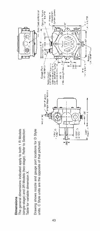
Dim
en
sio
ns
The g
enera
l dim
ensio
ns indic
ate
d a
pply
to b
oth
1 R
Models
(sin
gle
-sta
ge)
and 2
R M
odels
(tw
o-s
tage).
Refe
r to
Sele
ction
Table
for
variable
dim
ensio
n X
.
Dra
win
g s
how
s n
ozzle
and g
auge p
ort
locations f
or
D S
tyle
units.
C S
tyle
units a
re t
he o
pposite o
f th
at
pic
ture
d.
h126818 Capital City Tools_LN6331 4/26/16 10:23 AM Page 43

44
INS
Ta
ll
aT
ION
Da
Ta
R S
eries u
nits m
ay b
e u
sed i
n o
ne-
or
two-p
ipe i
nsta
llations.
Tw
o-p
ipe
opera
tion i
s r
ecom
mended f
or
all
hig
h c
apacity u
nits.
A y
ello
w t
ag i
s
attached t
o u
nits t
hat
are
facto
ry s
et
for
two-p
ipe insta
llation.
NO
TE
:In
let
port
s #
1 a
nd #
2,
and r
etu
rn p
ort
#2 a
re 3
/8”
pip
e t
hre
ad o
n
hig
h c
apacity u
nits.
(2R
6-8
Series.)
Unit s
how
n a
t th
e r
ight
has a
left s
ide b
y-p
ass p
lug a
ccess,
(-)
in t
he
sale
s c
ode. (*
) in
the c
ode d
esig
nate
s r
ight hand a
ccess a
s s
how
n b
elo
w.
To V
ent
Pum
p: A
ttach 1
/4”
ID p
lastic
tube.
Use 3
/8”
wre
nch t
o o
pen v
ent
1/8
turn
maxim
um
.
For
Use a
s G
auge P
ort
: R
em
ove insert
to insta
ll 1/8
” pip
e t
hre
aded g
age
Rem
ove p
lug t
o insta
ll1/4
” pip
e t
hre
aded g
auge.
Nozzle
Port
: 1/8
” pip
eth
read (
1/4
” pip
e t
hre
ad if
pum
p c
ode e
nds in 1
3 o
r 14
Inle
t P
ort
#2
1/4
” P
ipe T
hre
ad
“Insert
- (
Bypass P
lug 1
/8 p
ipe t
hre
ad)”
P/N
29533-3
5
3/1
6 A
llen
Retu
rn P
ort
#2
1/4
” P
ipe T
hre
ad,
use a
s r
etu
rn o
n
two p
ipe insta
llation
Retu
rn P
ort
#1:
1/4
” pip
e t
hre
ad,
used a
s r
etu
rn o
n t
wo p
ipe
insta
llation. P
ort
neare
st
pre
ssure
adju
sting s
cre
w is
never
used
Inle
t P
ort
#1
1/4
” P
ipe T
hre
ad
To A
dju
st
Pre
ssure
:R
em
ove c
over
scre
w.
Insert
1/8
Alle
nw
rench.
Turn
counte
r-clo
ckw
ise t
o b
elo
wpre
ssure
desired.
Turn
clo
ckw
ise t
o s
et
to d
esired p
ressure
.K
eep c
over
scre
wtight
except
when
adju
sting p
ressure
.
Retu
rn P
ort
#2:
1/4
” pip
e t
hre
ad,
used
as r
etu
rn o
n t
wo p
ipe insta
llation
Inle
t P
ort
#1:
1/4
”pip
e t
hre
ad
Inle
t P
ort
#2:
1/4
” pip
e
bO
DY
ST
Yl
E D
Cl
OC
KW
ISE
RO
Ta
TIO
Nb
OD
Y S
TY
lE
CC
OU
NT
ER
Cl
OC
KW
ISE
RO
Ta
TIO
N (
CC
W)
OP
PO
SIT
E O
f T
Ha
T P
ICT
UR
ED
h126818 Capital City Tools_LN6331 4/26/16 10:23 AM Page 44
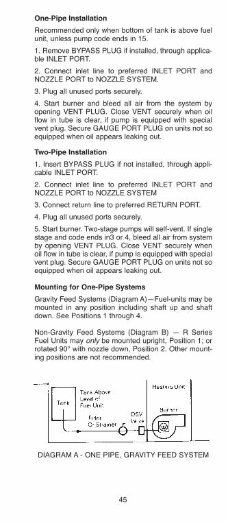
45
One-Pipe Installation
Recommended only when bottom of tank is above fuelunit, unless pump code ends in 15.
1. Remove BYPASS PLUG if installed, through applica-ble INLET PORT.
2. Connect inlet line to preferred INLET PORT andNOZZLE PORT to NOZZLE SYSTEM.
3. Plug all unused ports securely.
4. Start burner and bleed all air from the system byopening VENT PLUG. Close VENT securely when oilflow in tube is clear, if pump is equipped with specialvent plug. Secure GAUGE PORT PLUG on units not soequipped when oil appears leaking out.
Two-Pipe Installation
1. Insert BYPASS PLUG if not installed, through appli-cable INLET PORT.
2. Connect inlet line to preferred INLET PORT andNOZZLE PORT to NOZZLE SYSTEM
3. Connect return line to preferred RETURN PORT.
4. Plug all unused ports securely.
5. Start burner. Two-stage pumps will self-vent. If singlestage and code ends in3 or 4, bleed all air from systemby opening VENT PLUG. Close VENT securely whenoil flow in tube is clear, if pump is equipped with specialvent plug. Secure GAUGE PORT PLUG on units not soequipped when oil appears leaking out.
Mounting for One-Pipe Systems
Gravity Feed Systems (Diagram A)—Fuel-units may bemounted in any position including shaft up and shaftdown. See Positions 1 through 4.
Non-Gravity Feed Systems (Diagram B) — R SeriesFuel Units may only be mounted upright, Position 1; orrotated 90° with nozzle down, Position 2. Other mount-ing positions are not recommended.
DIAGRAM A - ONE PIPE, GRAVITY FEED SYSTEM
h126818 Capital City Tools_LN6331 4/26/16 10:23 AM Page 45
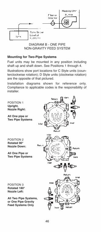
46
Mounting for Two-Pipe Systems
Fuel units may be mounted in any position includingshaft up and shaft down. See Positions 1 through 4.
Illustrations show port locations for C Style units (coun-terclockwise rotation); D Style units (clockwise rotation)are the opposite of that pictured.
Installation diagrams shown for reference only.Compliance to applicable codes is the responsibility ofinstaller.
POSITION 1Upright,Nozzle Right:
all One pipe orTwo Pipe Systems
POSITION 2Rotated 90°Nozzle Down:
all One Pipe orTwo Pipe Systems
POSITION 3Rotated 180°Nozzle left:
all Two Pipe Systems,or One Pipe Gravityfeed Systems Only
DIAGRAM B - ONE PIPENON-GRAVITY FEED SYSTEM
h126818 Capital City Tools_LN6331 4/26/16 10:23 AM Page 46
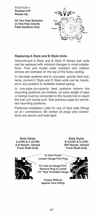
47
Replacing a Style and b Style Units
Discontinued A Style and B Style R Series fuel unitscan be replaced with minimal changes in most installa-tions. Fuel unit model code numbers and rotationarrows are stamped on the top of the body casting.
In two-pipe systems and in one-pipe, gravity feed sys-tems, current C Style and D Style units can be mount-ed in any position to facilitate easiest piping.
In one-pipe,non-gravity feed systems (where themounting positions are limited), an extra length of pipeor tubing must be connected to the nozzle line to reachthe fuel unit nozzle port. See previous page for permit-ted mounting positions.
Preferred installation calls for use of flare tube fittingson al I connections. Be certain all plugs and connec-tions are secure and leak-tight.
POSITION 4Rotated 270°Nozzle Up:
all Two Pipe Systems,or One Pipe Gravityfeed Systems Only
body Stylesa (CW) & C (CCW)(lH Nozzle, Viewed
from Shaft End)
body Stylesb (CCW) & D (CW)(RH Nozzle, Viewed
from Shaft End)
To Vent Pump:
loosen Gauge Port Plug
for Use as Gauge Port:Remove Plug to install
1/4” Pipe Threaded Gauge
Pumps WithoutSpecial Vent fitting
h126818 Capital City Tools_LN6331 4/26/16 10:23 AM Page 47

48
Typical Replacement Installations
Replace A Style units (clockwise rotation, nozzle port onleft, as viewed from shaft end) with D Style units (clock-wise rotation, nozzle port on right, as viewed from shaftend).
Standard a Style Installation:One or Two Pipe System
Replacement with D style,Rotated 180°: One Pipe, Gravity
feed System: or Two Pipe System
Replacement with D style,Nozzle line Extended: One Pipe,
Non-Gravity feed System
h126818 Capital City Tools_LN6331 4/26/16 10:23 AM Page 48

49
Replace B Style units (counterclockwise rotation, noz-zle port on right, as viewed from shaft end) with C Styleunits (counterclockwise rotation, nozzle port on left, asviewed from shaft end).
Standard b Style Installation:One or Two Pipe System
Replacement with C style,Rotated 180°: One Pipe, Gravity
feed System: or Two Pipe System
Replacement with C style,Nozzle line Extended: One Pipe,
Non-Gravity feed System
h126818 Capital City Tools_LN6331 4/26/16 10:23 AM Page 49

50
IMPORTaNT: Do not loosen or try to tighten any pumpplugs not to be used in the installation. NON-HARDEN-ING OIL PIPE DOPE IS RECOMMENDED for use onthe threads of all fittings. Paste must be used with careto prevent deposits on critical internal areas of thepump damage. Do not use teflon tape. EVIDENCE OFTEFLON TAPE USE WILL BE CAUSE TO VOID WAR-RANTY.
Installation Notes:
If the pump doesn’t work, check for air leaks.
If you’re experiencing the following problems;poor cutoff, noisy operation, erratic fire, check forair leaks.
� Return line must be submerged
� Check all fittings
� Check all joints
� Check optional inlet plugs
� DO NOT use compression fittings
90% of start-up problems are due to air leaks in the suc-tion line . . . so check � and double check � � for air leaks.
“Fuel unit inlet pressures should not exceed 3 psig inorder to comply with National Fire ProtectionAssociation’s Bulletin 31.”
Nozzle port pressure at cutoff is not less than 80% ofset pressure unless unit has blank nozzle or pump codeends in 13 or 14 (no cutoff).
To assure maximum performance, INLET VACUUM,measured at unused INLET PORT, should not exceed10” Hg on single-stage pumps or 15” Hg on two-stagepumps.
h126818 Capital City Tools_LN6331 4/26/16 10:23 AM Page 50
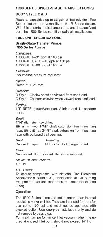
51
1R00 SERIES SINGlE-STaGE TRaNSfER PUMPS
bODY STYlE C & D
Rated at capacities up to 66 gph at 100 psi, the 1R00Series features the versatility of the R Series design.With 2 inlet ports, 4 discharge ports, and 1 gauge/ventport, the 1R00 Series can fit virtually all installations.
fUEl UNIT SPECIfICaTIONS
Single-Stage Transfer Pumps lR00 Series Pumps
Capacities:1R003-4EH—31 gph at 100 psi 1R004-4EH, 4EG—43 gph at 100 psi1R006-4EH—66 gph at 100 psi.
Pressure:No internal pressure regulator.
Speed: Rated at 1725 rpm.
Rotation:D Style—Clockwise when viewed from shaft end.C Style—Counterclockwise when viewed from shaft end.
Porting:1/4” NPTF: gauge/vent port, 2 inlets and 4 dischargeports.
Shaft:7/16” diameter, key drive.EH units have 1-7/8” shaft extension from mountingface. EG unit has 3-1/8” shaft extension from mountingface with outboard ball bearing.
Seal: Mounting:Double lip type. Hub or two bolt flange mount.
Filter:No internal filter. External filter recommended.
Maximum Inlet Vacuum:10” Hg.
U.L. Listed:To assure compliance with National Fire ProtectionAssociation’s Bulletin 31, “Installation of Oil BurningEquipment,” fuel unit inlet pressure should not exceed3 psig.
Operation
The 1R00 Series pumps do not incorporate an internalregulating valve or filter. They are intended for transferuse up to 100 psi and must not be operated withblocked outlet. Use one-pipe installation only and donot remove bypass plug.For maximum performance inlet vacuum, when meas-ured at unused inlet port, should not exceed 10” Hg.
h126818 Capital City Tools_LN6331 4/26/16 10:23 AM Page 51
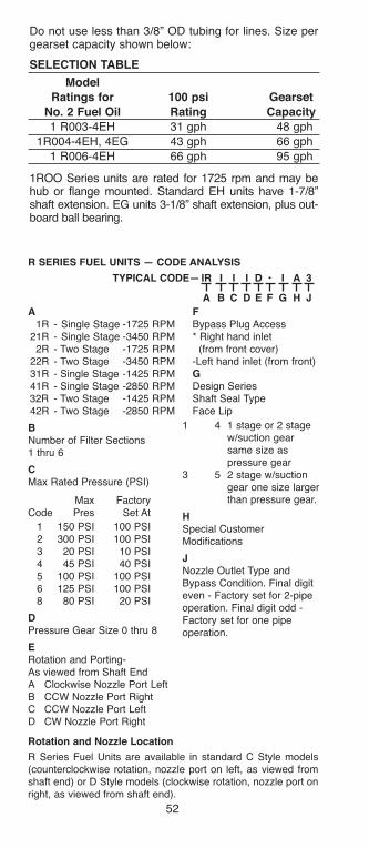
52
R SERIES fUEl UNITS — CODE aNalYSIS
a f1R - Single Stage -1725 RPM Bypass Plug Access
21R - Single Stage -3450 RPM * Right hand inlet 2R - Two Stage -1725 RPM (from front cover)
22R - Two Stage -3450 RPM -Left hand inlet (from front)31R - Single Stage -1425 RPM G41R - Single Stage -2850 RPM Design Series32R - Two Stage -1425 RPM Shaft Seal Type42R - Two Stage -2850 RPM Face Lip
bNumber of Filter Sections1 thru 6
CMax Rated Pressure (PSI)
Max FactoryCode Pres Set At
1 150 PSI 100 PSI2 300 PSI 100 PSI3 20 PSI 10 PSI4 45 PSI 40 PSI5 100 PSI 100 PSI6 125 PSI 100 PSI8 80 PSI 20 PSI
DPressure Gear Size 0 thru 8
ERotation and Porting-As viewed from Shaft EndA Clockwise Nozzle Port LeftB CCW Nozzle Port RightC CCW Nozzle Port LeftD CW Nozzle Port Right
Rotation and Nozzle location
R Series Fuel Units are available in standard C Style models(counterclockwise rotation, nozzle port on left, as viewed fromshaft end) or D Style models (clockwise rotation, nozzle port onright, as viewed from shaft end).
1 4 1 stage or 2 stagew/suction gearsame size aspressure gear
3 5 2 stage w/suctiongear one size largerthan pressure gear.
HSpecial CustomerModifications
jNozzle Outlet Type andBypass Condition. Final digiteven - Factory set for 2-pipeoperation. Final digit odd -Factory set for one pipeoperation.
TYPICal CODE— IR I I I D • I a 3
a b C D E f G H j
Do not use less than 3/8” OD tubing for lines. Size pergearset capacity shown below:
SElECTION TablE
ModelRatings for 100 psi Gearset
No. 2 fuel Oil Rating Capacity1 R003-4EH 31 gph 48 gph
1R004-4EH, 4EG 43 gph 66 gph
1 R006-4EH 66 gph 95 gph
1ROO Series units are rated for 1725 rpm and may behub or flange mounted. Standard EH units have 1-7/8”shaft extension. EG units 3-1/8” shaft extension, plus out-board ball bearing.
h126818 Capital City Tools_LN6331 4/26/16 10:23 AM Page 52
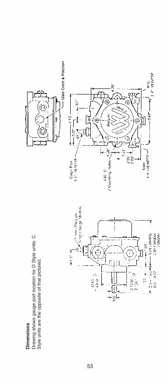
53
Dim
en
sio
ns
Dra
win
g s
how
s g
auge p
ort
location f
or
D S
tyle
units.
CS
tyle
units a
re t
he o
pposite o
f th
at
pic
ture
d.
h126818 Capital City Tools_LN6331 4/26/16 10:23 AM Page 53
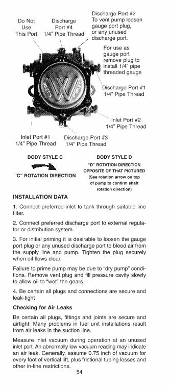
54
bODY STYlE C
“C” ROTaTION DIRECTION
Do NotUse
This Port
Discharge Port #11/4” Pipe Thread
Inlet Port #21/4” Pipe Thread
Discharge Port #31/4” Pipe Thread
Inlet Port #11/4” Pipe Thread
DischargePort #4
1/4” Pipe Thread
Discharge Port #2To vent pump loosengauge port plug,or any unuseddischarge port.
For use asgauge portremove plug toinstall 1/4” pipethreaded gauge
bODY STYlE D
“D” ROTaTION DIRECTION
OPPOSITE Of THaT PICTURED
(See rotation arrow on top
of pump to confirm shaft
rotation direction)
INSTallaTION DaTa
1. Connect preferred inlet to tank through suitable linefilter.
2. Connect preferred discharge port to external regula-tor or distribution system.
3. For initial priming it is desirable to loosen the gaugeport plug or any unused discharge port to bleed air fromthe supply line and pump. Tighten the plug securelywhen oil flows clear.
Failure to prime pump may be due to “dry pump” condi-tions. Remove vent plug and fill pressure cavity slowlyto allow oil to “wet” the gears.
4. Be certain all plugs and connections are secure andleak-tight
Checking for air leaks
Be certain all plugs, fittings and joints are secure andairtight. Many problems in fuel unit installations resultfrom air leaks in the suction line.
Measure inlet vacuum during operation at an unusedinlet port. An abnormally low vacuum reading may indicatean air leak. Generally, assume 0.75 inch of vacuum forevery foot of vertical lift, plus frictional tubing losses andother in-line restrictions.
h126818 Capital City Tools_LN6331 4/26/16 10:23 AM Page 54

55
V SERIES HIGH DElIVERY fUEl PUMPS
The V Series is designed to meet the high deliveryrequirements of commercial, industrial, and institutionalsystems with a minimum of mechanical and hydraulicnoise. Single-stage models can provide a firing rate upto 270 gph at up to 10” Hg inlet vacuum. Two-stage fir-ing rates are as high as 205 gph up to 15” Hg inlet vac-uum. Field adjustable integral regulating valves factorypre-set for 100 and 150 psi operation are offered as anoption to meet specific system requirements.
Single Stage
Two Stage
h126818 Capital City Tools_LN6331 4/26/16 10:23 AM Page 55

56
fUEl UNIT SPECIfICaTIONS
Single- and Two-Stage fuel-Units
V SeriesHigh Capacity fuel and Transfer Pumps
Capacities:Single-stage units: up to 180 gph with #2 oil, to 270 gphwith 1000 SSU oil.Two-stage units: up to 145 gph with #2 oil, to 205 gphwith 1000 SSU oil
NOTE: See rating table for capacity at specific pres-sure and rpm
Pressure:V02: Rated pressure 300 psi—factory set at 150 psi. V05: Rated pressure 100 psi—factory set at 100 psi. V08: Rated pressure 80 psi—factory set at 20 psi. V00: No internal regulation.
Speeds:1725 or 3450 rpm.
Rotation: D Style—clockwise when viewed from shaft end. C Style—counter clockwise when viewed from shaft end.
Porting:1/4” NPTF: gauge/optional nozzle port, nozzle port.3/8” NPTF: return port, 2 optional inlets.1/2” NPTF: inlet in cover
Shaft:DM Style—7/16” x 3.5” extension from mounting face.DO Style—7/16” x 1.88” extension from mounting face.
Seal:Double lip type.
Mounting:Hub or two bolt flange mount.
Filter:No internal filter. External Line filter recommended.
Maximum Inlet Vacuum:Single-stage units: 10” HgTwo-stage units: 15” Hg
U.L. Listed
h126818 Capital City Tools_LN6331 4/26/16 10:23 AM Page 56

57
SE
lE
CT
ION
Ta
bl
EN
OT
E:
Max.
Recom
mended F
irin
g R
ate
s a
pply
at
10”
Hg f
or
sin
gle
-sta
ge u
nits a
nd 1
5”
Hg f
or
two-s
tage u
nits
Sh
aft
1725
3450
1725
3450
1725
3450
1725
3450
1725
3450
V05 &
V02 S
eri
es S
ing
le-S
tag
e f
uel
Pu
mp
s (
wit
h I
nte
rnal
Reg
ula
tio
ns)
V052_-4
D_20
40
75
65
135
65
135
.25
.33
.25
.75
5.1
3
V056_-4
D_20
130
—190
—190
—.5
0—
.75
—5.1
3
V022_-4
D_20
20
60
50
120
50
120
.50
.75
.50
1.0
5.1
3
V023_-4
D_20
40
105
80
185
80
185
.50
1.0
0.5
01.5
5.1
3
V024_-4
D_20
60
140
110
240
110
240
.75
1.5
.75
2.0
5.1
3
V026_-4
D_20
95
—155
—155
—1.0
—1.0
—5.1
3
V028_-4
D_20
115
—190
—190
—1.5
—2.0
—5.6
7
2V
022_-5
D_20
20
60
50
120
100
205
.50
1.0
.50
1.5
5.6
7
2V
023_-5
D_20
40
105
80
185
140
270
.75
1.5
.75
2.0
6.1
7
2V
024_-5
D_20
60
—11
0—
200
—.7
5—
1.0
—6.7
1
2V
026_-5
D_20
95
—155
—250
—1.5
—1.5
—7.7
5
Max.
Reco
md
.f
irin
gR
ate
gp
h34S
SU
Max.
Reco
md
.f
irin
gR
ate
gp
h1000S
SU
Inle
t l
ine S
izin
gG
ear
Set
Cap
acit
yg
ph
34S
SU
th
ru1000S
SU
Reco
mm
en
ded
Mo
tor
h.p
.34S
SU
1000 S
SU
Dim
.a
100 p
si
Ratings
300 p
si
Ratings
300 p
si
Ratings
h126818 Capital City Tools_LN6331 4/26/16 10:23 AM Page 57
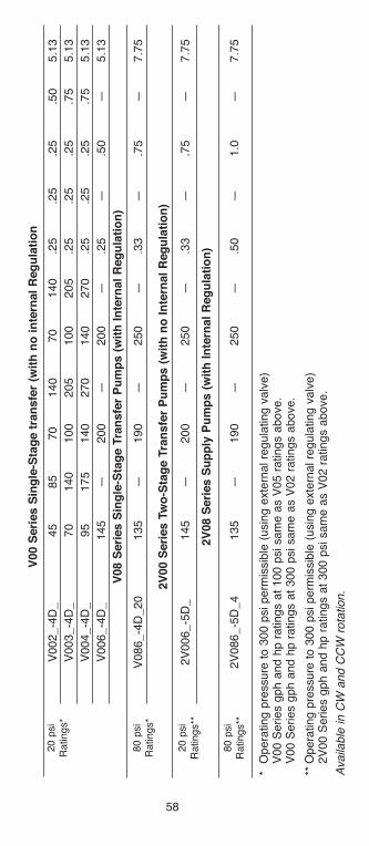
58
V00 S
eri
es S
ing
le-S
tag
e t
ran
sfe
r (w
ith
no
in
tern
al
Reg
ula
tio
n
V002_-4
D_
45
85
70
140
70
140
.25
.25
.25
.50
5.1
3
V003_-4
D_
70
140
100
205
100
205
.25
.25
.25
.75
5.1
3
V004_-4
D_
95
175
140
270
140
270
.25
.25
.25
.75
5.1
3
V006_-4
D_
145
—200
—200
—.2
5—
.50
—5.1
3
V08 S
eri
es S
ing
le-S
tag
e T
ran
sfe
r P
um
ps (
wit
h I
nte
rnal
Reg
ula
tio
n)
V086_-4
D_20
135
—190
—250
—.3
3—
.75
—7.7
5
2V
00 S
eri
es T
wo
-Sta
ge T
ran
sfe
r P
um
ps (
wit
h n
o I
nte
rnal
Reg
ula
tio
n)
2V
006_-5
D_
145
—200
—250
—.3
3—
.75
—7.7
5
2V
08 S
eri
es S
up
ply
Pu
mp
s (
wit
h I
nte
rnal
Reg
ula
tio
n)
2V
086_-5
D_4
135
—190
—250
—.5
0—
1.0
—7.7
5
*O
pera
ting p
ressure
to 3
00 p
si perm
issib
le (
usin
g e
xte
rnal re
gula
ting v
alv
e)
V00 S
eries g
ph a
nd h
p r
atings a
t 100 p
si sam
e a
s V
05 r
atings a
bove.
V00 S
eries g
ph a
nd h
p r
atings a
t 300 p
si sam
e a
s V
02 r
atings a
bove.
**O
pera
ting p
ressure
to 3
00 p
si perm
issib
le (
usin
g e
xte
rnal re
gula
ting v
alv
e)
2V
00 S
eries g
ph a
nd h
p r
atings a
t 300 p
si sam
e a
s V
02 r
atings a
bove.
Availa
ble
in C
W a
nd C
CW
rota
tion.
20 p
si
Ratings*
80 p
si
Ratings*
20 p
si
Ratings**
80 p
si
Ratings**
h126818 Capital City Tools_LN6331 4/26/16 10:23 AM Page 58
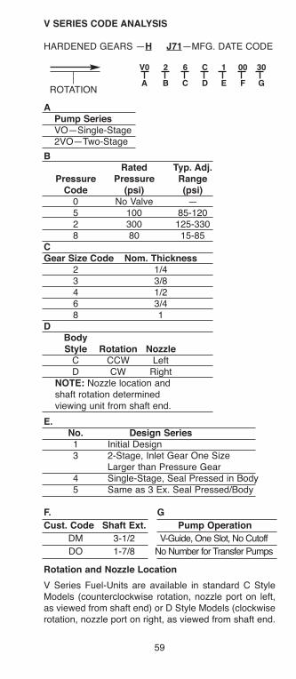
59
aPump SeriesVO—Single-Stage2VO—Two-Stage
bRated Typ. adj.
Pressure Pressure RangeCode (psi) (psi)
0 No Valve —5 100 85-1202 300 125-3308 80 15-85
CGear Size Code Nom. Thickness
2 1/43 3/84 1/26 3/48 1
DbodyStyle Rotation Nozzle
C CCW LeftD CW Right
NOTE: Nozzle location andshaft rotation determinedviewing unit from shaft end.
E.No. Design Series1 Initial Design3 2-Stage, Inlet Gear One Size
Larger than Pressure Gear4 Single-Stage, Seal Pressed in Body5 Same as 3 Ex. Seal Pressed/Body
f. G
Cust. Code Shaft Ext. Pump Operation
DM 3-1/2 V-Guide, One Slot, No Cutoff
DO 1-7/8 No Number for Transfer Pumps
Rotation and Nozzle location
V Series Fuel-Units are available in standard C StyleModels (counterclockwise rotation, nozzle port on left,as viewed from shaft end) or D Style Models (clockwiserotation, nozzle port on right, as viewed from shaft end.
V SERIES CODE aNalYSIS
HARDENED GEARS —H j71—MFG. DATE CODE
V0 2 6 C 1 00 30
a b C D E f GROTATION
h126818 Capital City Tools_LN6331 4/26/16 10:23 AM Page 59
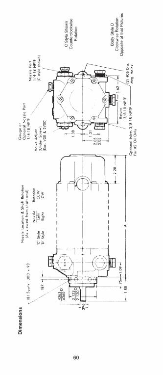
60
C S
tyle
Show
nC
ounte
rclo
ckw
ise
Rota
tion
Body S
tyle
DC
lockw
ise R
ota
tion
Opposite o
f th
at
Pic
ture
d
h126818 Capital City Tools_LN6331 4/26/16 10:23 AM Page 60
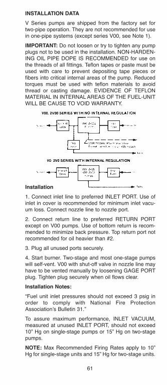
61
INSTallaTION DaTa
V Series pumps are shipped from the factory set fortwo-pipe operation. They are not recommended for usein one-pipe systems (except series V00, see Note 1).
IMPORTaNT: Do not loosen or try to tighten any pumpplugs not to be used in the installation. NON-HARDEN-ING OIL PIPE DOPE IS RECOMMENDED for use onthe threads of all fittings. Teflon tapes or paste must beused with care to prevent depositing tape pieces orfibers into critical internal areas of the pump. Reducedtorques must be used with teflon materials to avoidthread or casting damage. EVIDENCE OF TEFLONMATERIAL IN INTERNAL AREAS OF THE FUEL-UNITWILL BE CAUSE TO VOID WARRANTY.
Installation
1. Connect inlet line to preferred INLET PORT. Use ofinlet in cover is recommended for minimum inlet vacu-um loss. Connect nozzle line to nozzle port.
2. Connect return line to preferred RETURN PORTexcept on V00 pumps. Use of bottom return is recom-mended to minimize back pressure. Top return port notrecommended for oil heavier than #2.
3. Plug all unused ports securely.
4. Start burner. Two-stage and most one-stage pumpswill self-vent. V00 with shut-off valve in nozzle line mayhave to be vented manually by loosening GAGE PORTplug. Tighten plug securely when oil flows clear.
Installation Notes:
“Fuel unit inlet pressures should not exceed 3 psig inorder to comply with National Fire ProtectionAssociation’s Bulletin 31.”
To assure maximum performance, INLET VACUUM,measured at unused INLET PORT, should not exceed10” Hg on single-stage pumps or 15” Hg on two-stagepumps.
NOTE: Max Recommended Firing Rates apply to 10”Hg for single-stage units and 15” Hg for two-stage units.
h126818 Capital City Tools_LN6331 4/26/16 10:23 AM Page 61
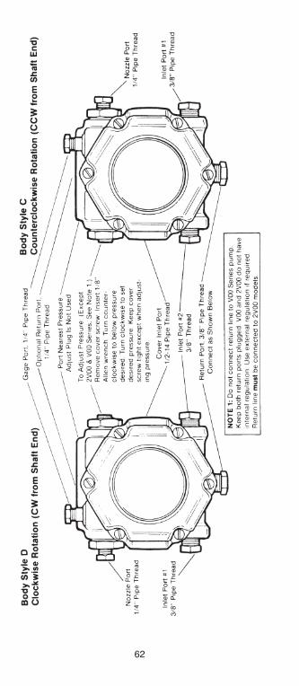
62
h126818 Capital City Tools_LN6331 4/26/16 10:23 AM Page 62
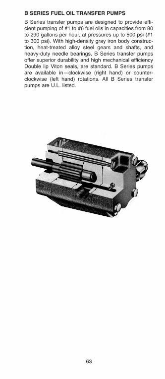
63
b SERIES fUEl OIl TRaNSfER PUMPS
B Series transfer pumps are designed to provide effi-cient pumping of #1 to #6 fuel oils in capacities from 80to 290 gallons per hour, at pressures up to 500 psi (#1to 300 psi). With high-density gray iron body construc-tion, heat-treated alloy steel gears and shafts, andheavy-duty needle bearings, B Series transfer pumpsoffer superior durability and high mechanical efficiencyDouble lip Viton seals, are standard. B Series pumpsare available in—clockwise (right hand) or counter-clockwise (left hand) rotations. All B Series transferpumps are U.L. listed.
h126818 Capital City Tools_LN6331 4/26/16 10:23 AM Page 63
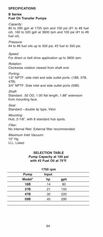
64
SPECIfICaTIONS
b Seriesfuel Oil Transfer Pumps
Capacity:80 to 290 gph at 1725 rpm and 100 psi (#1 to #6 fueloil). 160 to 520 gph at 3600 rpm and 100 psi (#1 to #6fuel oil).
Pressure:#4 to #6 fuel oils up to 500 psi, #2 fuel to 350 psi.
Speed:For direct or belt drive application up to 3600 rpm.
Rotation: Clockwise rotation viewed from shaft end.
Porting:1/2” NPTF: side inlet and side outlet ports. (18B, 37B,47B)3/4” NPTF: Side inlet and side outlet ports (59B)
Shaft:Standard: .50 OD, 1.00 flat length, 1.88” extensionfrom mounting face.
Seal:Standard—double lip type, Viton
Mounting:Hub, 2-1/8”, with 8 standard hub spots.
Filter:No internal filter. External filter recommended.
Maximum Inlet Vacuum:10” HgU.L. Listed
SElECTION TablEPump Capacity at 100 psiwith #2 fuel Oil at 75°f.
1750 rpm
Pump Input
Model* hp gph
18b .14 80
37b .21 155
47b .30 220
59b .45 290
h126818 Capital City Tools_LN6331 4/26/16 10:23 AM Page 64

65
PSI300
200
100
25
25300
PSI300
200
100
25
25300
18B
37B
h126818 Capital City Tools_LN6331 4/26/16 10:23 AM Page 65

66
PSI300
200
100
25
25100300
PSI300
200
100
25
25300
47B
59B
h126818 Capital City Tools_LN6331 4/26/16 10:23 AM Page 66

67
INSTallaTION aND DIMENSIONal DaTa
Single-Rotation Models
Connect discharge and suction lines to NPTF portsdepending on desired direction of shaft rotation.Direction of shaft rotation is always toward dischargeport.
CaUTION: Do not attempt to operate pump with dis-charge port blocked.
Correct shaft rotation is shown by arrow stamped onback of pump. Do not attempt to operate pump in oppo-site direction. Use an external regulating valve in discharge line ifpressure regulation is necessary.
Installation Notes:
“Fuel unit inlet pressure should not exceed 3 psig inorder to comply with National Fire ProtectionAssociation’s Bulletin 31“
To assure maximum performance, INLET VACUUM,measured at unused INLET PORT, should not exceed10” Hg on single-stage pumps.
CODE DIM “A” DIM “B”
18B 3.36 2.66
37B 3.71 3.02
47B 4.05 2.13
59B 4.40 2.30
2.123
1.00
1.35
500
1.87
.44
.5000
A
B
h126818 Capital City Tools_LN6331 4/26/16 10:23 AM Page 67
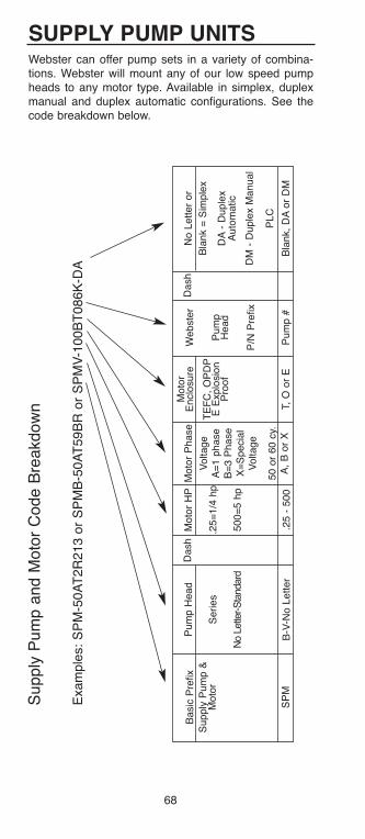
68
SUPPlY PUMP UNITSWebster can offer pump sets in a variety of combina-tions. Webster will mount any of our low speed pumpheads to any motor type. Available in simplex, duplexmanual and duplex automatic configurations. See thecode breakdown below.
Supply
Pum
p a
nd M
oto
r C
ode B
reakdow
n
Exam
ple
s:
SP
M-5
0A
T2R
213 o
r S
PM
B-5
0A
T59B
R o
r S
PM
V-1
00B
T086K
-DA
Basic
Pre
fix
Supply
Pum
p &
Moto
r
SP
M
Pum
p H
ead
Series
No L
ette
r-S
tandard
B-V
-No L
etter
Dash
Moto
r H
P
.25=
1/4
hp
500=
5 h
p
.25 -
500
Moto
r P
hase
Voltage
A=
1 p
hase
B=
3 P
hase
X=
Specia
lV
oltage
50 o
r 60 c
y.A
, B
or
X
Moto
rE
nclo
sure
TE
FC
, O
PD
PE
Explo
sio
nP
roof
T,
O o
r E
Dash
Webste
r
Pum
pH
ead
P/N
Pre
fix
Pum
p #
No L
etter
or
Bla
nk =
Sim
ple
x
DA
- D
uple
xA
uto
matic
DM
- D
uple
x M
anual
PLC
Bla
nk,
DA
or
DM
h126818 Capital City Tools_LN6331 4/26/16 10:23 AM Page 68
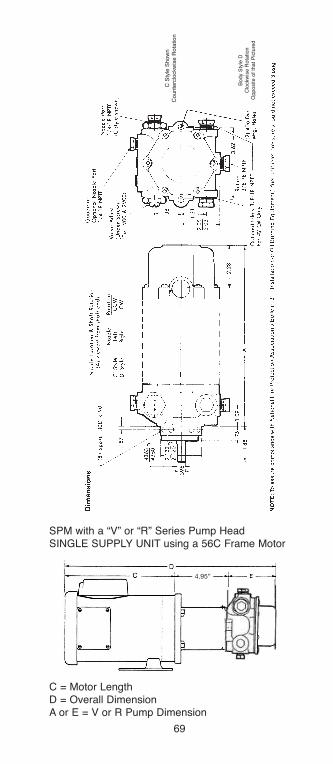
69
C = Motor LengthD = Overall DimensionA or E = V or R Pump Dimension
SPM with a “V” or “R” Series Pump HeadSINGLE SUPPLY UNIT using a 56C Frame Motor
C S
tyle
Sh
ow
nC
ou
nte
rclo
ckw
ise
Ro
tatio
n
Body S
tyle
DC
lockw
ise R
ota
tion
Opposite o
f th
at
Pic
ture
d
4.95”
h126818 Capital City Tools_LN6331 4/26/16 10:23 AM Page 69
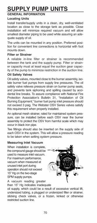
SUPPlY PUMP UNITSGENERal INfORMaTION
locating Units
Install transfer/supply units in a clean, dry, well-ventilatedlocation as close to the storage tank as possible. Closeinstallation will minimize required vacuum and will allowsmallest diameter piping to be used while assuring an ade-quate supply of oil.
The units can be mounted in any position. Preferred posi-tion for convenient line connections is horizontal with footmounts down.
filter or Strainer
A reliable in-line filter or strainer is recommendedbetween the tank and the supply pump. Filter or strain-er capacity must at least equal the suction gear capac-ity of the pump to minimize restriction in the suction line.
Oil Safety Valves
Oil safety valves, mounted close to the burner assembly, iso-late burner fuel pumps from supply line pressures. The oilsafety valve relieves pressure strain on burner pump seals,and prevents tank siphoning and spilling caused by acci-dental line breaks. To assure compliance with National FireProtection Association’s Bulletin 31, “Installation of OilBurning Equipment,” burner fuel pump inlet pressure shouldnot exceed 3 psig. The Webster OSV Series valves satisfythis requirement when properly installed.
An optional mesh strainer, rated for maintained system pres-sure, can be installed before each OSV near the burnerassembly to protect the OSV from harmful scale which mayoccur in black iron pipe.
Tee fittings should also be inserted on the supply side ofeach OSV in the system. This will allow a pressure readingto be taken when setting system pressure.
Measuring Inlet Vacuum
When installation is complete,the compound gauge should beused to measure inlet vacuum. For maximum performance, vacuum when measured atunused inlet port duringoperation should not exceed15” Hg on the two-stageSPM supply pumps.
A vacuum reading greaterthan 15” Hg indicates inadequateoil supply, which could be a result of excessive vertical lift,undersized tubing, a plugged or undersized filter or strainer,sticking check valves, or a frozen, kinked or otherwiserestricted suction line.
70
h126818 Capital City Tools_LN6331 4/26/16 10:23 AM Page 70
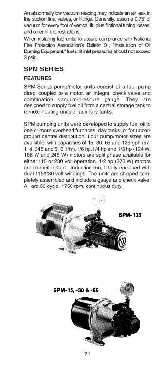
SPM SERIES
fEaTURES
SPM Series pump/motor units consist of a fuel pumpdirect coupled to a motor. an integral check valve andcombination vacuum/pressure gauge. They aredesigned to supply fuel oil from a central storage tank toremote heating units or auxiliary tanks.
SPM pumping units were developed to supply fuel oil toone or more overhead furnaces, day tanks, or for under-ground central distribution. Four pump/motor sizes areavailable, with capacities of 15, 30, 65 and 135 gph (57,114, 245 and 510 1/hr).1/6 hp,1/4 hp and 1/3 hp (124 W,186 W and 248 W) motors are split phase available foreither 115 or 230 volt operation. 1/2 hp (373 W) motorsare capacitor start—induction run, totally enclosed withdual 115/230 volt windings. The units are shipped com-pletely assembled and include a gauge and check valve.All are 60 cycle, 1750 rpm, continuous duty.
An abnormally low vacuum reading may indicate an air leak inthe suction line, valves, or fittings. Generally, assume 0.75” ofvacuum for every foot of vertical lift, plus frictional tubing losses,and other in-line restrictions.
When installing fuel units, to assure compliance with NationalFire Protection Association’s Bulletin 31, “Installation of OilBurning Equipment,” fuel unit inlet pressures should not exceed3 psig.
71
h126818 Capital City Tools_LN6331 4/26/16 10:23 AM Page 71
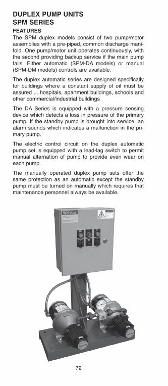
DUPlEX PUMP UNITS SPM SERIESfEaTURESThe SPM duplex models consist of two pump/motorassemblies with a pre-piped, common discharge mani-fold. One pump/motor unit operates continuously, withthe second providing backup service if the main pumpfails. Either automatic (SPM-DA models) or manual(SPM-DM models) controls are available.
The duplex automatic series are designed specificallyfor buildings where a constant supply of oil must beassured ... hospitals, apartment buildings, schools andother commercial/industrial buildings
The DA Series is equipped with a pressure sensingdevice which detects a loss in pressure of the primarypump. If the standby pump is brought into service, analarm sounds which indicates a malfunction in the pri-mary pump.
The electric control circuit on the duplex automaticpump set is equipped with a lead-lag switch to permitmanual alternation of pump to provide even wear oneach pump.
The manually operated duplex pump sets offer thesame protection as an automatic except the standbypump must be turned on manually which requires thatmaintenance personnel always be available.
72
h126818 Capital City Tools_LN6331 4/26/16 10:23 AM Page 72
73
SUPPlY UNIT SPECIfICaTIONS
SPM Series Supply Units
Single and Duplex
Capacities:15, 30, 65, and 135 gph
Pressure:Maximum operating pressure to 80 psi or 200’ of head.
Motors: All motors are 60 cycle, 1750 rpm, continuous duty, 48Nframe, 1/6, 1/4, 1/3 hp: split phase, 115 or 230 volt oper-ation, 1/2 hp: capacitor start/induction run, TEFC, dual115/230 volt.
Pumps:SPM 15, 30, and 65: uses Webster “2R” Series pumpunits.SPM 135: uses the Webster ‘2V” Series pump unit.Webster 2R and 2V are UL listed
Porting:SPM 15, 30, 65:
1/4” NPTF—2 inlets, outlet port and top and bottom returns
SPM 135:1/4” NPTF—outlet port3/8” NPTF—return port, 2 optional inlets.1/2” NPTF—inlet.
Seal: All models—double lip type.
Mounting:All models — four bolt foot mount
Filter:Rotary self cleaning type, except in SPM 135. Use ofexternal line filter recommended.
Valves:Pressure regulating assembly in pump maintains set pressure.Check valve maintains oil in feeder lines for instantstarts.
Gauge:2-1/2” dia., calibrated from 30” vacuum to 100 psi.
Controls: Two Types for Duplex Units Only Duplex automatic withlead-lag switch and alarm. Manual with selector switch.
Maximum Inlet Vacuum:All units—15” Hg
National Fire Protection Association compliancerequires fuel inlet pressure not to exceed 3 psig.
NEMA 1Enclosure
h126818 Capital City Tools_LN6331 4/26/16 10:23 AM Page 73

SE
lE
CT
ION
Ta
bl
EM
od
els
an
d D
esig
n D
ata
Tab
le 1
Max f
low
Max.
Watt
s@
min
.M
ax f
low
Pu
mp
Mo
tor
Mo
tor
Head
Valv
e a
dj.
@ 8
0p
si
@ 8
0 p
si
Su
cti
on
Mo
del
Mo
del
Typ
eV
olt
ag
eh
pft
*R
an
ge
psi
gp
hg
ph
Cap
.N
o.
SP
M-1
5-1
Sin
gle
115
SP
M-1
5-2
Sin
gle
230
SP
M-1
5-1
-DA
Duple
x-A
uto
.11
51/6
200’
10 t
o 1
00 p
si
65
22
15
35
2R
181C
-5B
Q4
SP
M-1
5-2
-DA
Duple
x-A
uto
.230
(35196-5
)
SP
M-1
5-1
-DM
Duple
x-M
an
115
SP
M-1
5-2
-DM
Duple
x-M
an
230
SP
M-3
0-1
Sin
gle
115
SP
M-3
0-2
Sin
gle
230
SP
M-3
0-1
-DA
Duple
x-A
uto
115
1/4
200’
10 t
o 1
00 p
si
95
45
30
70
2R
283C
-5B
Q4
SP
M-3
0-2
-DA
Duple
x-A
uto
230
(35196-6
)
SP
M-3
0-1
-DM
Duple
x-M
an
115
SP
M-3
0-2
-DM
Duple
x-M
an
230
SP
M-6
5-1
Sin
gle
115
SP
M-6
5-2
Sin
gle
230
74
h126818 Capital City Tools_LN6331 4/26/16 10:23 AM Page 74
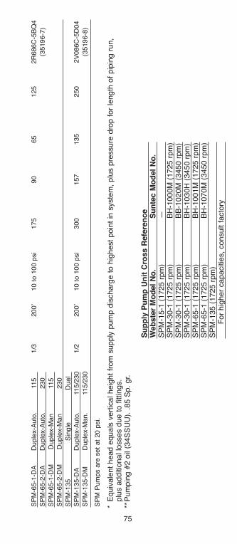
75
SP
M-6
5-1
-DA
Duple
x-A
uto
.11
51/3
200’
10 t
o 1
00 p
si
175
90
65
125
2R
686C
-5B
Q4
SP
M-6
5-2
-DA
Duple
x-A
uto
.230
(35196-7
)
SP
M-6
5-1
-DM
Duple
x-M
an
115
SP
M-6
5-2
-DM
Duple
x-M
an
230
SP
M-1
35
Sin
gle
Dual
SP
M-1
35-D
AD
uple
x-A
uto
.11
5/2
30
1/2
200’
10 t
o 1
00 p
si
300
157
135
250
2V
086C
-5D
04
SP
M-1
35-D
MD
uple
x-M
an.
115/2
30
(35196-8
)
SP
M P
um
ps a
re s
et
at
20 p
si.
*E
quiv
ale
nt
head e
quals
vert
ical heig
ht
from
supply
pum
p d
ischarg
e t
o h
ighest
poin
t in
syste
m,
plu
s p
ressure
dro
p f
or
length
of
pip
ing r
un,
plu
s a
dditio
nal lo
sses d
ue t
o f
ittings.
**P
um
pin
g #
2 o
il (3
4S
SU
U).
.85 S
p.
gr.
Su
pp
ly P
um
p U
nit
Cro
ss R
efe
ren
ce
Web
ste
r M
od
el
No
.S
un
tec M
od
el
No
.S
PM
-15-1
(1725 r
pm
)—
SP
M-3
0-1
(1725 r
pm
)B
H-1
000M
(1725 r
pm
)S
PM
-30-1
(1725 r
pm
)B
B-1
020M
(3450 r
pm
)S
PM
-30-1
(1725 r
pm
)B
H-1
030H
(3450 r
pm
)S
PM
-65-1
(1725 r
pm
)B
H-1
001M
(1725 r
pm
)S
PM
-65-1
(1725 r
pm
)B
H-1
070M
(3450 r
pm
)S
PM
-135 (
1725 r
pm
)F
or
hig
her
capacitie
s,
consult f
acto
ry
h126818 Capital City Tools_LN6331 4/26/16 10:23 AM Page 75
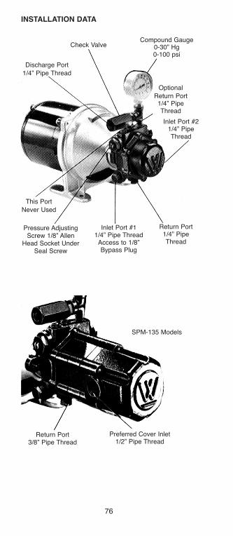
INSTallaTION DaTa
Compound Gauge0-30” Hg0-100 psi
Check Valve
Discharge Port
1/4” Pipe Thread
This Port
Never Used
Pressure AdjustingScrew 1/8” Allen
Head Socket UnderSeal Screw
SPM-135 Models
Preferred Cover Inlet1/2” Pipe Thread
Return Port3/8” Pipe Thread
Optional
Return Port1/4” PipeThread
Inlet Port #21/4” PipeThread
Return Port1/4” PipeThread
Inlet Port #11/4” Pipe ThreadAccess to 1/8”Bypass Plug
76
h126818 Capital City Tools_LN6331 4/26/16 10:23 AM Page 76
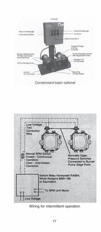
77
Wiring for intermittent operation
h126818 Capital City Tools_LN6331 4/26/16 10:23 AM Page 77
78
DUPlEX fUEl OIl PUMP SETSWebster has the ability to offer pump sets in a variety ofcombinations. Webster will mount any of our low speedpump heads to any AC motor and panel type. DuplexAutomatic and Duplex Manual configurations.
Standard Duplex Operation and featuresThe SPM duplex models consist of two pump/motorassemblies with a pre-piped, common discharge mani-fold. One pump/motor unit operates continuously, withthe second providing backup service if the main pumpfails. Either automatic (SPM-DA models) or manual(SPM-DM models) controls are available.
The duplex automatic series are designed specificallyfor buildings where a constant supply of oil must beassured...hospitals, apartment buildings, schools andother commercial/industrial buildings.
The DA Series is equipped with a pressure sensingdevice which detects a loss in pressure of the primarypump. If the standby pump is brought into service, analarm sounds which indicates a malfunction in the pri-mary pump.
The electric control circuit on the duplex automaticpump set is equipped with a lead-lag to permit alterationof pump to provide even wear on each pump.
The manually operated duplex pump sets offer thesame protection as an automatic except the standbypump must be turned on manually which requires thatmaintenance personnel always be available.
h126818 Capital City Tools_LN6331 4/26/16 10:23 AM Page 78
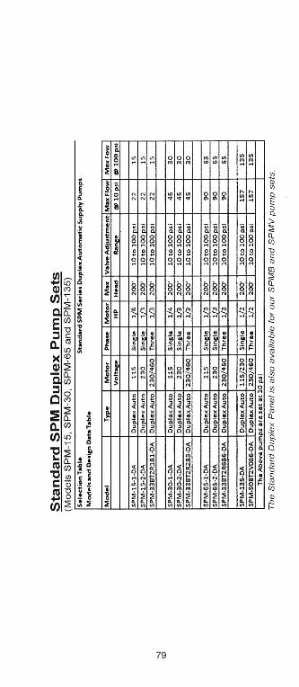
79
h126818 Capital City Tools_LN6331 4/26/16 10:23 AM Page 79
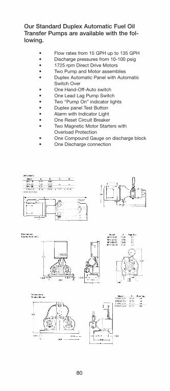
80
Our Standard Duplex Automatic Fuel OilTransfer Pumps are available with the fol-lowing.
• Flow rates from 15 GPH up to 135 GPH• Discharge pressures from 10-100 psig• 1725 rpm Direct Drive Motors• Two Pump and Motor assemblies• Duplex Automatic Panel with Automatic
Switch Over• One Hand-Off-Auto switch• One Lead Lag Pump Switch• Two “Pump On” indicator lights• Duplex panel Test Button• Alarm with Indicator Light• One Reset Circuit Breaker• Two Magnetic Motor Starters with
Overload Protection• One Compound Gauge on discharge block• One Discharge connection
MODELS “A”
PIPE THD SIZE
SPM-15-( )-DA 14.94
h126818 Capital City Tools_LN6331 4/26/16 10:23 AM Page 80

81
INSTallaTION DaTa
SPM Single and Duplex Manual Models
SPM Single and Duplex Manual units are capable ofsupplying fuel oil to heating units or tanks located up to200 feet above the supply pumps. They are designedfor use in maintained pressure or open loop systems.Pump pressures can be set at a range from 10 psi to100 psi. See Correct Supply Line Size charts, for maxi-mum discharge head.
Tank to Pump Connections
Connect suction line from the tank to preferred supplypump inlet port. Connect return line from pump returnport to tank. Internal 1/8" bypass plug (factory installed)must be in position for recommended two-pipe opera-tion. Be certain all plugs and connections are secureand leak tight.
The correct suction line size can be determined byreferring to the charts. Generally, the return line shouldbe sized the same as the suction line. Check valves inthe suction lines between the tank and SPM unitsassure that pumps are full of oil, ready for service.Check valves must be oil tight. Low pressure dropswing type are recommended to minimize friction loss.
For SPM Duplex Manual models, preferred installationcalls for a separate suction line from tank to pump foreach pump/motor unit. If system failure occurs becauseof a gross leak in the suction line of the primary unit, thesecond unit can still provide backup service. Checkvalves can be installed in return lines to allow removalof inactive pump for servicing, while primary pump con-tinues to run.
These typical installation diagrams, illustrating a main-tained pressure supply system or optional open loopsystem, for continuous pump operation, are shown forreference only. Compliance to all applicable codeswhere installed is the sole responsibility of the installer.
h126818 Capital City Tools_LN6331 4/26/16 10:23 AM Page 81

*R
equired if
optional re
turn
lo
op is n
ot
used
+N
ot
supplie
d b
y W
ebste
r
+
+*
+
+ +
82
h126818 Capital City Tools_LN6331 4/26/16 10:23 AM Page 82

83
SPM Duplex automatic Models
SPM Duplex Automatic units consist of two SPM Seriespump/motor assemblies and an electrical control panel.They are designed for use in maintained pressure sup-ply systems only. if system pressure falls below a pre-set level, the control automatically switches from the pri-mary pump/motor unit to the secondary unit. If the backuppump/motor unit also fails to reach or maintain presetsystem pressure, the control also shuts off the backupunit.
A pump selector switch allows the two pump/motor unitsto be manually alternated for even wear on each pump.Pump pressures can be set at a range from 10 psi to100 psi. See Correct Supply Line charts, for maximumdischarge head.
Tank to Pump Connections
Units should be set for two-pipe operation. Preferredinstallation calls for a separate suction line from tank topump for each pump/motor unit. If system failure occursbecause of a gross leak in the suction line of the primaryunit, the second unit can still provide backup service.
The correct suction line size can be determined byreferring to the charts Generally, the return line shouldbe sized the same as the suction line. Low pressuredrop, swing type check valves can be installed in thesuction lines, assuring that pumps are full of oil, readyfor service. Check valves in return lines allow removalof inactive pump for servicing. Use of shutoff valves inreturn lines is not recommended. Be certain all plugsand connections are secure and leak-tight.
+ Not supplied by Webster
+ +
h126818 Capital City Tools_LN6331 4/26/16 10:23 AM Page 83
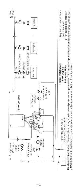
+ + +
+
+
+
*
*R
equired if
optional re
turn
lo
op is n
ot
used
+N
ot
supplie
d b
y W
ebste
r
84
h126818 Capital City Tools_LN6331 4/26/16 10:23 AM Page 84
85
SPM lINE SIZING
Correct sizing of the suction and discharge linesbetween the storage tank and supply unit is vital. Theuse of tubing or pipe which is too small can result inrestricted oil supply. The following charts are listed tohelp in line sizing for supply unit installation.
The charts can assist in determining the suggested min-imum suction and discharge line sizes for StandardSchedule 40 iron or steel pipe (IPS) and for Type K cop-per tubing, which is recommended for undergroundservice.*
To use the line sizing charts, first a supply unit must besized to meet the specific application. Once this hasbeen accomplished, the unit model number (ex. SPM-30) should be used as a guide in referring to the correctsuction and/or discharge sizing charts.
NOTE: The use of pipe or tubing which is too small cancause increased frictional losses. The result could be aninadequate system discharge pressure. Check localand state codes pertaining to oil heating systems forany requirements which may affect the installationand/or operation of the system.
The following charts apply to all SPM Single, SPMDuplex Manual and SPM Duplex Automatic models.These charts are not intended to be used in sizing pipefor any other supply or transfer pump/motor units.
*Charts represent maximum horizontal run vs. verticallift or vertical head for Standard Schedule 40 iron orsteel pipe (lPS) and for Type K copper tubing, recom-mended for underground service. The actual OD andwall thickness are indicated for each tube size. (NOTE:The nominal size of Type K tubing is 1/8” smaller thanactual OD.)
h126818 Capital City Tools_LN6331 4/26/16 10:23 AM Page 85
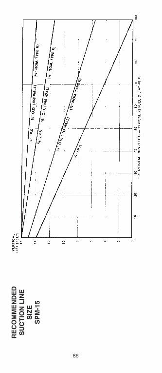
RE
CO
MM
EN
DE
DS
UC
TIO
N l
INE
SIZ
ES
PM
-15
86
h126818 Capital City Tools_LN6331 4/26/16 10:23 AM Page 86
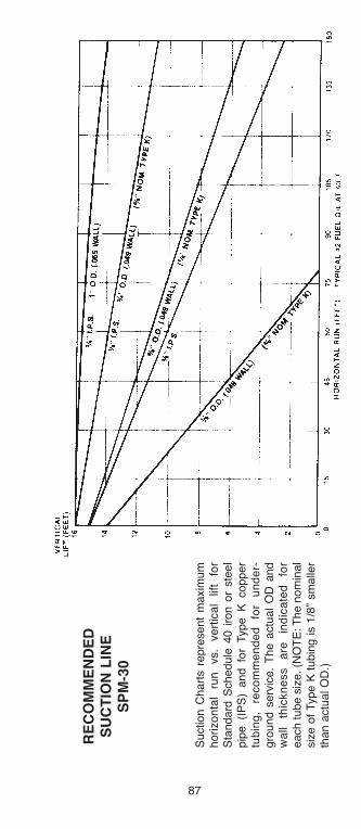
87
RE
CO
MM
EN
DE
DS
UC
TIO
N l
INE
SP
M-3
0
Suction C
hart
s r
epre
sent
maxim
um
ho
rizo
nta
l ru
n
vs.
ve
rtic
al
lift
for
Sta
ndard
Schedule
40 i
ron o
r ste
el
pip
e (I
PS
) and fo
r Type K
copper
tub
ing
, re
co
mm
en
de
d
for
un
de
r-gro
und s
erv
ice.
The a
ctu
al
OD
and
wa
ll th
ickn
ess
are
in
dic
ate
d
for
each tube s
ize. (N
OT
E: T
he n
om
inal
siz
e o
f Type K
tubin
g is 1
/8”
sm
alle
rth
an a
ctu
al O
D.)
h126818 Capital City Tools_LN6331 4/26/16 10:23 AM Page 87

RE
CO
MM
EN
DE
DS
UC
TIO
N l
INE
SIZ
ES
PM
-65
88
h126818 Capital City Tools_LN6331 4/26/16 10:24 AM Page 88
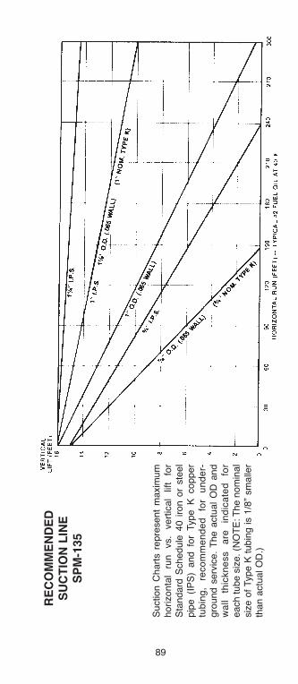
89
RE
CO
MM
EN
DE
DS
UC
TIO
N l
INE
SP
M-1
35
Suction C
hart
s r
epre
sent
maxim
um
ho
rizo
nta
l ru
n
vs.
ve
rtic
al
lift
for
Sta
ndard
Schedule
40 i
ron o
r ste
el
pip
e (I
PS
) and fo
r Type K
copper
tub
ing
, re
co
mm
en
de
d
for
un
de
r-gro
und s
erv
ice.
The a
ctu
al
OD
and
wa
ll th
ickn
ess
are
in
dic
ate
d
for
each tube s
ize. (N
OT
E: T
he n
om
inal
siz
e o
f Type K
tubin
g is 1
/8”
sm
alle
rth
an a
ctu
al O
D.)
h126818 Capital City Tools_LN6331 4/26/16 10:24 AM Page 89

RE
CO
MM
EN
DE
DD
ISC
Ha
RG
E l
INE
SIZ
ES
PM
-15
90
h126818 Capital City Tools_LN6331 4/26/16 10:24 AM Page 90

91
RE
CO
MM
EN
DE
DD
ISC
Ha
RG
E l
INE
SP
M-3
0
Dis
charg
e C
hart
s re
pre
sent
maxi-
mum
horizonta
l ru
n v
s.
vert
ical
lift
for
Sta
ndard
S
chedule
40 iron or
ste
el pip
e (
IPS
) and for
Type K
cop-
pe
r tu
bin
g,
reco
mm
en
de
d
for
un
de
rgro
un
d
se
rvic
e.
Th
e
actu
al
OD
and w
all
thic
kness a
re in
dic
ate
dfo
r each
tube
siz
e.
(NO
TE
: T
he
nom
inal s
ize o
f Type K
tubin
g is
1/8
”sm
alle
r th
an a
ctu
al O
D.)
h126818 Capital City Tools_LN6331 4/26/16 10:24 AM Page 91

RE
CO
MM
EN
DE
DD
ISC
Ha
RG
E l
INE
SIZ
ES
PM
-65
92
h126818 Capital City Tools_LN6331 4/26/16 10:24 AM Page 92

93
RE
CO
MM
EN
DE
DD
ISC
Ha
RG
E l
INE
SP
M-1
35
Dis
charg
e
Chart
s
repre
sent
maxi-
mum
horizonta
l run v
s. vert
ical l
ift fo
rS
tandard
Schedule
40 i
ron o
r ste
el
pip
e (I
PS
) and fo
r Type K
copper
tub
ing
, re
co
mm
en
de
d
for
un
de
r-gro
und s
erv
ice.
The a
ctu
al
OD
and
wa
ll th
ickn
ess
are
in
dic
ate
d
for
each tube s
ize. (N
OT
E: T
he n
om
inal
siz
e o
f Type K
tubin
g is 1
/8”
sm
alle
rth
an a
ctu
al O
D.)
h126818 Capital City Tools_LN6331 4/26/16 10:24 AM Page 93
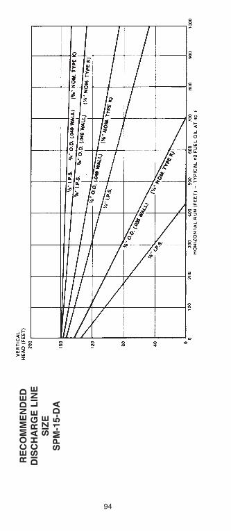
RE
CO
MM
EN
DE
DD
ISC
Ha
RG
E l
INE
SIZ
ES
PM
-15-D
a
94
h126818 Capital City Tools_LN6331 4/26/16 10:24 AM Page 94

95
RE
CO
MM
EN
DE
DD
ISC
Ha
RG
E l
INE
SP
M-3
0-D
a
Dis
charg
e
Chart
s
repre
sent
maxi-
mum
horizonta
l run v
s. vert
ical l
ift fo
rS
tandard
Schedule
40 i
ron o
r ste
el
pip
e (I
PS
) and fo
r Type K
copper
tub
ing
, re
co
mm
en
de
d
for
un
de
r-gro
und s
erv
ice.
The a
ctu
al
OD
and
wa
ll th
ickn
ess
are
in
dic
ate
d
for
each tube s
ize. (N
OT
E: T
he n
om
inal
siz
e o
f Type K
tubin
g is 1
/8”
sm
alle
rth
an a
ctu
al O
D.)
h126818 Capital City Tools_LN6331 4/26/16 10:24 AM Page 95
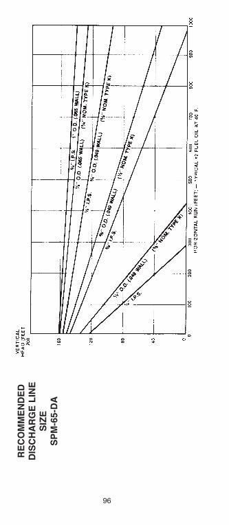
RE
CO
MM
EN
DE
DD
ISC
Ha
RG
E l
INE
SIZ
ES
PM
-65-D
a
96
h126818 Capital City Tools_LN6331 4/26/16 10:24 AM Page 96
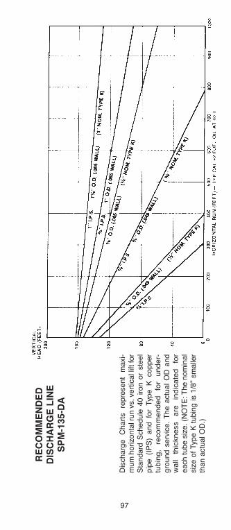
97
RE
CO
MM
EN
DE
DD
ISC
Ha
RG
E l
INE
SP
M-1
35-D
a
Dis
charg
e
Chart
s
repre
sent
maxi-
mum
horizonta
l run v
s. vert
ical l
ift fo
rS
tandard
Schedule
40 i
ron o
r ste
el
pip
e (I
PS
) and fo
r Type K
copper
tub
ing
, re
co
mm
en
de
d
for
un
de
r-gro
und s
erv
ice.
The a
ctu
al
OD
and
wa
ll th
ickn
ess
are
in
dic
ate
d
for
each tube s
ize. (N
OT
E: T
he n
om
inal
siz
e o
f Type K
tubin
g is 1
/8”
sm
alle
rth
an a
ctu
al O
D.)
h126818 Capital City Tools_LN6331 4/26/16 10:24 AM Page 97

The adjusting screws on the Pressuretrol, located in thefactory wired control panel, should be set carefullyaccording to instructions, below.
Setting Pump Pressure
1. Set the differential scale indicator on the pressuretrolat approximately 5 (half-way between 10 and bottom ofscale). This permanently sets the differential scale. Setmain scale indicator at 0, so supply pump can run con-tinuously during purging of supply line.
2. Purge lines. Run both supply pumps to assure bothare oil filled. For priming purposes, OSV valves can bemanually operated by inserting a stiff wire (paper clip)through the cover hole, and depressing the diaphragmplate.
3. Pressure adjustment, pump one: Install compoundgauge in tee fitting in supply line of highest or mostremote burner. After starting pump one, start all burn-ers. With all burners operating at maximum firing rate,adjust pump one so gauge at remote burners, reads 20 psi.
4 Pressuretrol adjustment: With all burners firing, switchto pump two and adjust pump two so gauge at lastburner reads slight positive pressure (2-5 psi).Gradually increase the pressuretrol main scale settinguntil pump two stops, pump one starts, and alarmbuzzer sounds. Allow pump one to run and build pres-sure. With pump one running and pump two off, turnpump two pressure adjusting screw about one-quarterturn clockwise.
5. Pressure adjustment, pump two: Move selectorswitch to off momentarily, then back to pump two. Alarmwill shut off and pump two will start. Adjust pump twopressure setting so it is the same as pump one (set instep three). Switch back and forth between both pumps
DifferentialScale
AdjustingScrew
Main Scale
AdjustingScrew
MainScale
Indicator
DifferentialScale
Indicator
SPM Duplex automatic Controls
98
h126818 Capital City Tools_LN6331 4/26/16 10:24 AM Page 98
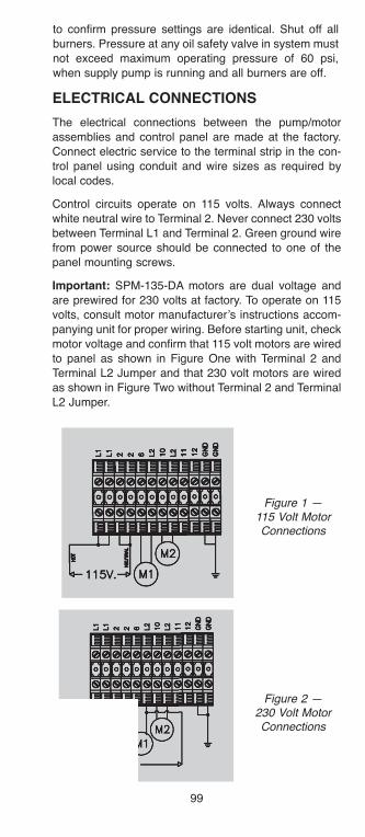
99
to confirm pressure settings are identical. Shut off all
burners. Pressure at any oil safety valve in system must
not exceed maximum operating pressure of 60 psi,
when supply pump is running and all burners are off.
ElECTRICal CONNECTIONS
The electrical connections between the pump/motor
assemblies and control panel are made at the factory.
Connect electric service to the terminal strip in the con-
trol panel using conduit and wire sizes as required by
local codes.
Control circuits operate on 115 volts. Always connect
white neutral wire to Terminal 2. Never connect 230 volts
between Terminal L1 and Terminal 2. Green ground wire
from power source should be connected to one of the
panel mounting screws.
Important: SPM-135-DA motors are dual voltage and
are prewired for 230 volts at factory. To operate on 115
volts, consult motor manufacturer’s instructions accom-
panying unit for proper wiring. Before starting unit, check
motor voltage and confirm that 115 volt motors are wired
to panel as shown in Figure One with Terminal 2 and
Terminal L2 Jumper and that 230 volt motors are wired
as shown in Figure Two without Terminal 2 and Terminal
L2 Jumper.
Figure 1 — 115 Volt MotorConnections
Figure 2 —230 Volt MotorConnections
h126818 Capital City Tools_LN6331 4/26/16 10:24 AM Page 99
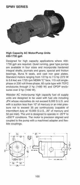
SPMV SERIES
High Capacity aC Motor/Pump Units 430-1730 gph
Designed for high capacity applications where 430-
1730 gph are required. Quiet running, gear type pumps
are available in four sizes and incorporate hardened
integral shafts, journals and gears, special anti friction
bearings, Buna N seals, and cast iron gear plates.
Standard motors ranging from 1/2 hp to 7.5 hp (373 W
to 5.6 kw) are 1725 rpm NEMA “C” face, 115 volt single-
phase or 230 volt three-phase, 60 cycle type with TEFC
enclosures through 2 hp (1490 W) and OPDP enclo-
sures over 2 hp (1490 W).
Webster AC motor/pump high capacity fuel oil supply
units are designed to be used with fuel oils including
JP4 whose viscosities do not exceed 6,000 S.U.S. and
with a suction less than 10” of mercury or an inlet pres-
sure not to exceed 35 psi continuously (capable of
intermittent duty at 10,000 S.U.S., 20” of mercury and
50 psi inlet). The unit is designed to operate in -20°F to
+200°F conditions. The motor is precision aligned and
coupled to the pump with a machined adapter and flex-
ible couplings.
100
h126818 Capital City Tools_LN6331 4/26/16 10:24 AM Page 100
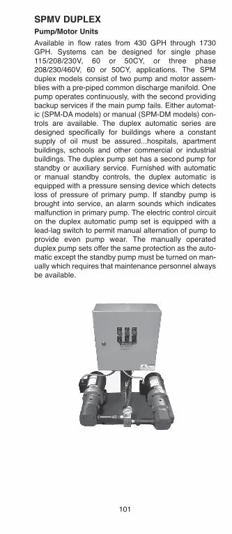
101
SPMV DUPlEXPump/Motor Units
Available in flow rates from 430 GPH through 1730GPH. Systems can be designed for single phase115/208/230V, 60 or 50CY, or three phase208/230/460V, 60 or 50CY, applications. The SPMduplex models consist of two pump and motor assem-blies with a pre-piped common discharge manifold. Onepump operates continuously, with the second providingbackup services if the main pump fails. Either automat-ic (SPM-DA models) or manual (SPM-DM models) con-trols are available. The duplex automatic series aredesigned specifically for buildings where a constantsupply of oil must be assured...hospitals, apartmentbuildings, schools and other commercial or industrialbuildings. The duplex pump set has a second pump forstandby or auxiliary service. Furnished with automaticor manual standby controls, the duplex automatic isequipped with a pressure sensing device which detectsloss of pressure of primary pump. If standby pump isbrought into service, an alarm sounds which indicatesmalfunction in primary pump. The electric control circuiton the duplex automatic pump set is equipped with alead-lag switch to permit manual alternation of pump toprovide even pump wear. The manually operatedduplex pump sets offer the same protection as the auto-matic except the standby pump must be turned on man-ually which requires that maintenance personnel alwaysbe available.
h126818 Capital City Tools_LN6331 4/26/16 10:24 AM Page 101

SPECIfICaTIONSSPMV SERIES
aC High Capacity fuel Oil Supply Units
Capacity:430 to 1730 gph with fluid viscosity to 10,000 SSU.
Pressure:Inlet pressure should not to exceed 3 psi. Outlet pressure up to 500 psi.
Fluid Temperature Limits: -20° F to +200° F.
Motors:Standard: 60 cycle, 1750 rpm, NEMA 56C frame.1/2 through 7 1/2 hp available.To be specified when ordering: Single-phase 115/230VAC, or three-phase 230/460 VAC. ODP or TEFC.
Porting: 1” NPT (086K-194K)1 1/2 X 1 1/4 NPT (237K-388K)
Mounting: Integral mounting foot.
Maximum Inlet Vacuum: 15” HgContinuous operation: 10” HgUse of external filter recommended.
In applying these supply units, the pressures indicatedare at the pump outlet. You must also consider line losses.
All pumps relying on atmospheric pressure to push thefuel oil into them are subject to cavitation. As fuel vis-cosity (thickness) increases, the tendency for cavitationbecomes greater. Therefore, it is best to mount thepump at the base of the tank and to use the largestdiameter, shortest length, and straightest inlet possible.A large diameter inlet pipe or hose necked down at thepump is preferable to a longer length of smaller diame-ter pipe because the fuel tends to adhere to the insideof the pipe.
When initially starting a unit, it is desirable and some-times necessary to have a vent valve or plug on thepressure side of the pump to facilitate its priming.
102
h126818 Capital City Tools_LN6331 4/26/16 10:24 AM Page 102
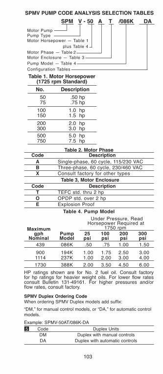
103
SPMV PUMP CODE aNalYSIS SElECTION TablES
SPM V - 50 a T /086K Da
Motor PumpPump TypeMotor Horsepower — Table 1
plus Table 4
Motor Phase — Table 2
Motor Enclosure — Table 3
Pump Model — Table 4
Configuration Tables
Table 1. Motor Horsepower(1725 rpm Standard)
No. Description
50 .50 hp75 .75 hp
100 1.0 hp150 1.5 hp
200 2.0 hp300 3.0 hp
500 5.0 hp750 7.5 hp
Table 2. Motor PhaseCode Description
a Single-phase, 60 cycle, 115/230 VACb Three-phase, 60 cycle, 230/460 VACX Consult factory for other types
Table 3, Motor Enclosure
Code Description
T TEFC std. thru 2 hp
O OPDP std. over 2 hp
E Explosion Proof
Table 4. Pump Model
Under Pressure, ReadHorsepower Required at
1750 rpmMaximumgph Pump 25 100 200 300
Nominal Model psi psi psi psi
439 086K .50 .75 1.00 1.50
900 194K 1.00 1.75 2.50 3.001114 237K 1.00 2.00 3.00 4.00
1730 388K 2.00 3.50 4.50 6.00
HP ratings shown are for No. 2 fuel oil. Consult factoryfor hp ratings for heavier weight oils. For lower flow ratesconsult Bulletin 131-49161. For higher pressures and/orflow rates, consult factory.
SPMV Duplex Ordering CodeWhen ordering SPMV Duplex models add suffix:
“DM,” for manual control models, or “DA,” for automatic controlmodels.
Example: SPMV-50AT/086K-DA
5 Code Duplex Units
DM Duplex with manual controls
DA Duplex with automatic controls
h126818 Capital City Tools_LN6331 4/26/16 10:24 AM Page 103
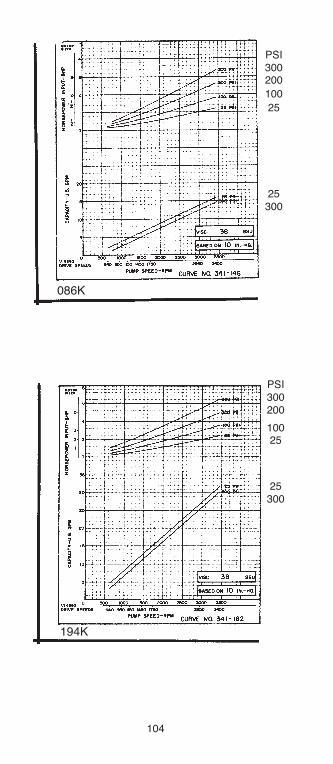
PSI300200
100
25
25300
PSI300200
10025
25300
086K
194K
104
h126818 Capital City Tools_LN6331 4/26/16 10:24 AM Page 104
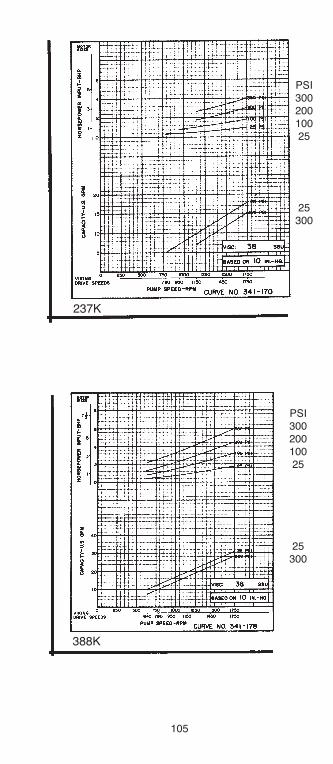
105
PSI30020010025
25300
PSI30020010025
25300
237K
388K
h126818 Capital City Tools_LN6331 4/26/16 10:24 AM Page 105
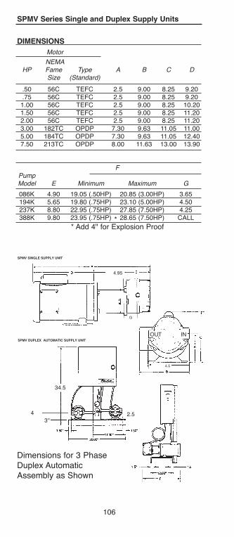
4.95
DIMENSIONS
Motor
NEMAHP Fame Type A B C D
Size (Standard)
.50 56C TEFC 2.5 9.00 8.25 9.20
.75 56C TEFC 2.5 9.00 8.25 9.201.00 56C TEFC 2.5 9.00 8.25 10.201.50 56C TEFC 2.5 9.00 8.25 11.202.00 56C TEFC 2.5 9.00 8.25 11.203.00 182TC OPDP 7.30 9.63 11.05 11.005.00 184TC OPDP 7.30 9.63 11.05 12.407.50 213TC OPDP 8.00 11.63 13.00 13.90
FPumpModel E Minimum Maximum G
086K 4.90 19.05 (.50HP) 20.85 (3.00HP) 3.65194K 5.65 19.80 (.75HP) 23.10 (5.00HP) 4.50237K 8.80 22.95 (.75HP) 27.85 (7.50HP) 4.25388K 9.80 23.95 (.75HP) 28.65 (7.50HP) CALL
* Add 4" for Explosion Proof
SPMV Series Single and Duplex Supply Units
Dimensions for 3 PhaseDuplex AutomaticAssembly as Shown
SPMV SINGlE SUPPlY UNIT
SPMV DUPlEX aUTOMaTIC SUPPlY UNIT
34.5
4
3''2.5
106
*
OUT IN
G
4.5
h126818 Capital City Tools_LN6331 4/26/16 10:24 AM Page 106
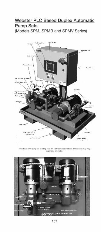
107
The above SPM pump set is sitting on a 36” x 24” containment basin. Dimensions may varydepending on model.
Webster PLC Based Duplex AutomaticPump Sets(Models SPM, SPMB and SPMV Series)
h126818 Capital City Tools_LN6331 4/26/16 10:24 AM Page 107
108
The Duplex automatic Pump and Motor PlC basedOil Management Control Panel options below arepre-programmed into the PlC.
• Microprocessor Base Programmable Logic Controller• Remote Monitoring Capabilities via Ethernet and or
Wireless Communication. Internet connection is need-ed to interface with the PLC panel in order to providereal time remote monitoring.
• Audio and Visual Alarm• Duplex Automatic Panel with Automatic Switch Over• High/Low Level and Leak Detection Interface with
Alarm and Shut Down• Automatic Alternation will allow for equal run time
between pump sets every 14 days• Pressure Transducer to detect pump failure and to
allow back-up pump to energize• 6” LED Touch Display Panel• Vacuum and Pressure Monitoring• Motor Starters with MCP’s (Motor circuit protector)• Quick Disconnect• ETM Time Elapsed Recorders for Each Pump Set for
Later Verification• Event Summary• NEMA 4/12 Enclosure• Control System is equipped to monitor and control
1. Hand-Off-Automatic Control2. Lead Pump Selection - Auto/Manual3. Pump Status - Off/Run/Standby4. Pressure and Vacuum Status-Normal/High/Low5. Main Tank/Day Tank Status-
Normal/High/Low/Leak• Controllers are field expandable using plug-in input
modules to monitor up to 4 storage tanks and 12 dis-criminating leak sensors.
• Motor Faiure Alarm• Light to indicate normal power on, run, and off condi-
tions• Remote HMI Access for real time remote monitoring
and control (C’more HMI APP Download Required)• Advanced features of Touch Panel: Remote Access
and Control feature. Send email with embedded PLCdata, Send logged data to an external PC, retrievelogged panel data remotely via the internet, and clearold logged data on a routing frequency. Unit can com-municate with different brands of PLC’s at the sametime.
h126818 Capital City Tools_LN6331 4/26/16 10:24 AM Page 108
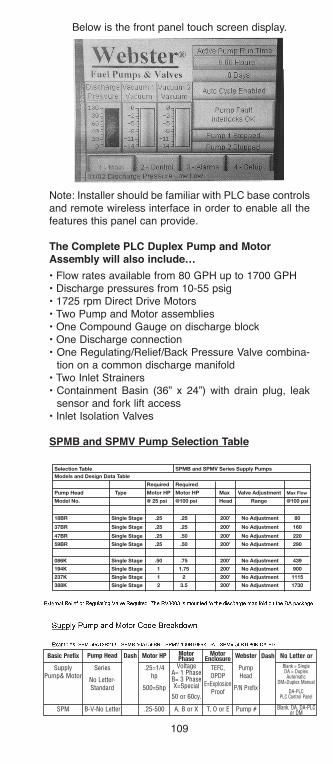
Note: Installer should be familiar with PLC base controlsand remote wireless interface in order to enable all thefeatures this panel can provide.
The Complete PlC Duplex Pump and Motorassembly will also include…
• Flow rates available from 80 GPH up to 1700 GPH• Discharge pressures from 10-55 psig• 1725 rpm Direct Drive Motors• Two Pump and Motor assemblies• One Compound Gauge on discharge block• One Discharge connection• One Regulating/Relief/Back Pressure Valve combina-
tion on a common discharge manifold• Two Inlet Strainers• Containment Basin (36” x 24”) with drain plug, leak
sensor and fork lift access • Inlet Isolation Valves
SPMb and SPMV Pump Selection Table
Selection Table SPMB and SPMV Series Supply PumpsModels and Design Data Table
Required Required
Pump Head Type Motor HP Motor HP Max Valve Adjustment Max Flow
Model No. @ 25 psi @100 psi Head Range @100 psi
18BR Single Stage .25 .25 200’ No Adjustment 80
37BR Single Stage .25 .25 200’ No Adjustment 160
47BR Single Stage .25 .50 200’ No Adjustment 220
59BR Single Stage .25 .50 200’ No Adjustment 290
086K Single Stage .50 .75 200’ No Adjustment 439
194K Single Stage 1 1.75 200’ No Adjustment 900
237K Single Stage 1 2 200’ No Adjustment 1115
388K Single Stage 2 3.5 200’ No Adjustment 1730
109
Below is the front panel touch screen display.
Basic Prefix
SupplyPump& Motor
Series
No Letter-Standard
.25=1/4hp
500=5hp
TEFC,OPDP
E=ExplosionProof
PumpHead
P/N Prefix
Blank = SingleDA = DuplexAutomatic
DM=Duplex Manual
DA-PLCPLC Control Panel
VoltageA= 1 PhaseB= 3 PhaseX=Special
50 or 60cy.
SPM .25-500 A, B or X T, O or E Pump # Blank, DA, DA-PLCor DMB-V-No Letter
Pump Head Dash DashWebsterMotor HP MotorPhase
MotorEnclosure No Letter or
h126818 Capital City Tools_LN6331 4/26/16 10:24 AM Page 109
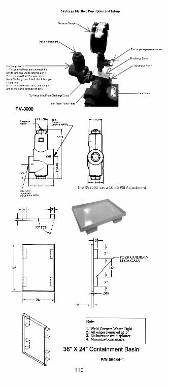
110
h126818 Capital City Tools_LN6331 4/26/16 10:24 AM Page 110
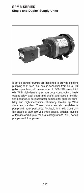
111
SPMb SERIESSingle and Duplex Supply Units
B series transfer pumps are designed to provide efficientpumping of #1 to #6 fuel oils, in capacities from 80 to 290gallons per hour, at pressures up to 500 PSI (except #1oil). With high-density gray iron body construction, heat-treated alloy steel gears and shafts, and special antifric-tion bearings, B series transfer pumps offer superior dura-bility and high mechanical efficiency. Double lip Vitonseals are standard. These pumps are also available inpump and motor packages. Available in 115/230 volt sin-gle phase or 230/460 volt three phase, simplex, duplexautomatic and duplex manual configurations. All B seriespumps are UL approved.
h126818 Capital City Tools_LN6331 4/26/16 10:24 AM Page 111
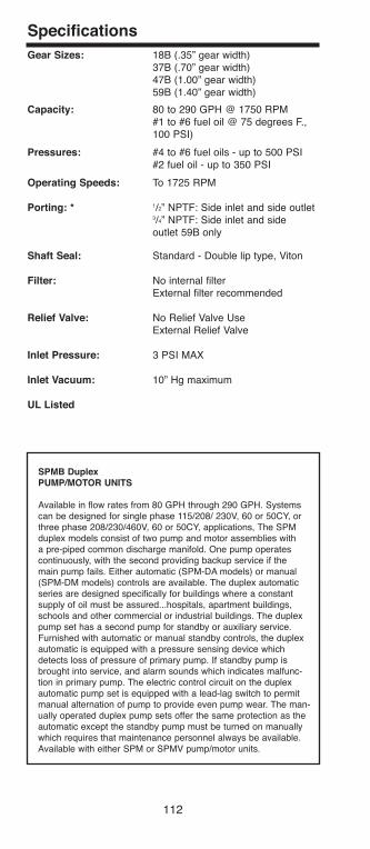
Specifications
Gear Sizes: 18B (.35” gear width)37B (.70” gear width)47B (1.00” gear width)59B (1.40” gear width)
Capacity: 80 to 290 GPH @ 1750 RPM#1 to #6 fuel oil @ 75 degrees F.,100 PSI)
Pressures: #4 to #6 fuel oils - up to 500 PSI#2 fuel oil - up to 350 PSI
Operating Speeds: To 1725 RPM
Porting: * 1/2” NPTF: Side inlet and side outlet3/4” NPTF: Side inlet and sideoutlet 59B only
Shaft Seal: Standard - Double lip type, Viton
filter: No internal filterExternal filter recommended
Relief Valve: No Relief Valve Use External Relief Valve
Inlet Pressure: 3 PSI MAX
Inlet Vacuum: 10” Hg maximum
Ul listed
SPMb DuplexPUMP/MOTOR UNITS
Available in flow rates from 80 GPH through 290 GPH. Systemscan be designed for single phase 115/208/ 230V, 60 or 50CY, orthree phase 208/230/460V, 60 or 50CY, applications, The SPMduplex models consist of two pump and motor assemblies witha pre-piped common discharge manifold. One pump operatescontinuously, with the second providing backup service if themain pump fails. Either automatic (SPM-DA models) or manual(SPM-DM models) controls are available. The duplex automaticseries are designed specifically for buildings where a constantsupply of oil must be assured...hospitals, apartment buildings,schools and other commercial or industrial buildings. The duplexpump set has a second pump for standby or auxiliary service.Furnished with automatic or manual standby controls, the duplexautomatic is equipped with a pressure sensing device whichdetects loss of pressure of primary pump. If standby pump isbrought into service, and alarm sounds which indicates malfunc-tion in primary pump. The electric control circuit on the duplexautomatic pump set is equipped with a lead-lag switch to permitmanual alternation of pump to provide even pump wear. The man-ually operated duplex pump sets offer the same protection as theautomatic except the standby pump must be turned on manuallywhich requires that maintenance personnel always be available.Available with either SPM or SPMV pump/motor units.
112
h126818 Capital City Tools_LN6331 4/26/16 10:24 AM Page 112
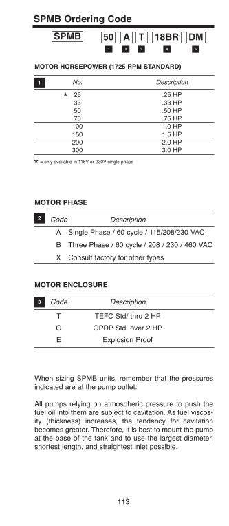
113
MOTOR HORSEPOWER (1725 RPM STaNDaRD)
No. Description
25 .25 HP
33 .33 HP
50 .50 HP
75 .75 HP
100 1.0 HP
150 1.5 HP
200 2.0 HP
300 3.0 HP
= only available in 115V or 230V single phase
MOTOR PHaSE
Code Description
A Single Phase / 60 cycle / 115/208/230 VAC
B Three Phase / 60 cycle / 208 / 230 / 460 VAC
X Consult factory for other types
MOTOR ENClOSURE
Code Description
T TEFC Std/ thru 2 HP
O OPDP Std. over 2 HP
E Explosion Proof
SPMb Ordering Code
SPMb 50 a T 18bR DM1
1
2
3
2 3 4 5
When sizing SPMB units, remember that the pressuresindicated are at the pump outlet.
All pumps relying on atmospheric pressure to push thefuel oil into them are subject to cavitation. As fuel viscos-ity (thickness) increases, the tendency for cavitationbecomes greater. Therefore, it is best to mount the pumpat the base of the tank and to use the largest diameter,shortest length, and straightest inlet possible.
*
*
h126818 Capital City Tools_LN6331 4/26/16 10:24 AM Page 113
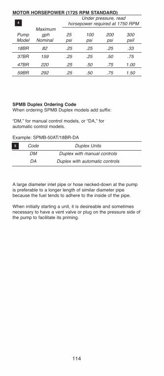
MOTOR HORSEPOWER (1725 RPM STaNDaRD)Under pressure, read
horsepower required at 1750 RPMMaximum
Pump gph 25 100 200 300Model Nominal psi psi psi psiI
18BR 82 .25 .25 .25 .33
37BR 159 .25 .25 .50 .75
47BR 220 .25 .50 .75 1.00
59BR 292 .25 .50 .75 1.50
SPMb Duplex Ordering CodeWhen ordering SPMB Duplex models add suffix:
“DM,” for manual control models, or “DA,” forautomatic control models.
Example: SPMB-50AT/18BR-DA
Code Duplex Units
DM Duplex with manual controls
DA Duplex with automatic controls
4
5
A large diameter inlet pipe or hose necked-down at the pumpis preferable to a longer length of similar diameter pipebecause the fuel tends to adhere to the inside of the pipe.
When initially starting a unit, it is desireable and sometimesnecessary to have a vent valve or plug on the pressure side ofthe pump to facilitate its priming.
114
h126818 Capital City Tools_LN6331 4/26/16 10:24 AM Page 114

115
SPMb Series Single and Duplex Supply Units
DIMENSIONS
Motor
NEMA
HP Fame Type A B C
Size (Standard)
.50 56C TEFC 9.00 8.25 9.20
.75 56C TEFC 9.00 8.25 9.20
1.00 56C TEFC 9.00 8.25 10.20
1.50 56C TEFC 9.00 8.25 11.20
2.00 56C TEFC 9.00 8.25 11.20
3.00 182TC OPDP 9.63 11.05 11.00
5.00 184TC OPDP 9.63 11.05 12.40
7.50 213TC OPDP 11.63 13.00 13.90
Pump
Model E D
18BR 3.36 (.50HP) 17.06
37BR 3.71 (.75HP) 17.41
47BR 4.05 (.75HP) 17.75
59BR 4.40 (.75HP) 18.10
h126818 Capital City Tools_LN6331 4/26/16 10:24 AM Page 115
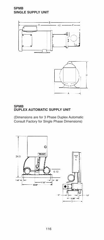
SPMbSINGlE SUPPlY UNIT
SPMbDUPlEX aUTOMaTIC SUPPlY UNIT
(Dimensions are for 3 Phase Duplex Automatic
Consult Factory for Single Phase Dimensions)
34.5
6.12
116
h126818 Capital City Tools_LN6331 4/26/16 10:24 AM Page 116

117
TRaNSfER PUMP UNITSTransfer pumps/motors consist of an electric motor andWebster fuel unit. Each Webster fuel unit has beendesigned for a variety of needs from fuel supply to fueltransfer. With capacities ranging from 9 to 150 gph at100 psi, Webster transfer units are capable of satisfyingvirtually every system supply or transfer need.
SPECIfICaTIONS
35223 Series, 35202 Series, 49116 Series
Capacities:35223 Series—80 to 155 gph at 100 psi. 35202 Series—9 to 65 gph at 100 psi. 49116 Series—31 to 66 gph at 100 psi.
Maximum Working Pressure:35223 Series—80 to 200 psi.35202 Series—100 to 300 psi.49116 Series—100 psi
Motors:All motors 60 cycle, 1750 rpm, continuous duty 115 volt. 1/6 and 1/4 hp are split phase.1/2hp is capacitor start—induction run, TEFC with dual115/230 volt windings.
Fuel Units (Close Coupled to Motor):
35223 Series uses Websters’ B Series Fuel Oil TransferUnits.35202 Series uses Websters’ V Series or R Series FuelUnits.
49116 Series uses Websters’ 1R00 Series FuelTransfer Units.
Mounting: Maximum Inlet Vacuum:Four bolt foot mount. 10” Hg vacuum.
Use of external filter recommended.
35223 SERIES TRaNSfER UNITS
The 35223 Series Pump/Motor Unit consists of aWebster B Series fuel oil transfer pump close coupledto a 1/4 hp electric motor. This unit is designed for trans-fer of fuel oils #6 or lighter at maximum working pres-sures up to 200 PSI depending on motor hp.
h126818 Capital City Tools_LN6331 4/26/16 10:24 AM Page 117

SE
lE
CT
ION
Ta
bl
E
35223 S
eri
es P
um
p/M
oto
r U
nit
s
Maxim
um
Maxim
um
Mo
tor
Mo
tor
Pu
mp
Wo
rkin
gO
utl
et
flo
wD
im. a
Mo
dels
Vo
ltag
eh
oM
od
el
Pre
ssu
reat
100p
si
(max.)
Dim
. b
35223-1
115
1/4
18B
200 p
si
80 g
ph
16.0
46.3
2
35223-3
115
1/4
37B
100 p
si
155 g
ph
16.3
96.6
7
118
h126818 Capital City Tools_LN6331 4/26/16 10:24 AM Page 118
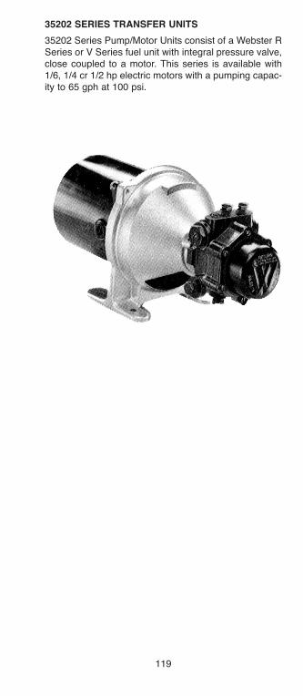
119
35202 SERIES TRaNSfER UNITS
35202 Series Pump/Motor Units consist of a Webster RSeries or V Series fuel unit with integral pressure valve,close coupled to a motor. This series is available with1/6, 1/4 cr 1/2 hp electric motors with a pumping capac-ity to 65 gph at 100 psi.
h126818 Capital City Tools_LN6331 4/26/16 10:24 AM Page 119

SE
lE
CT
ION
Ta
bl
E
Maxim
um
Pu
mp
gp
h a
tW
ork
ing
blo
cked
Maxim
um
Su
cti
on
Mo
tor
Mo
tor
Mo
tor
fu
el
un
itP
ressu
reN
ozz
leg
ph
at
Wo
rkin
gC
ap
acit
yM
od
els
Vo
ltag
eTyp
e N
o.
hp
Typ
e N
o.
psi
Watt
s100 p
si
Pre
ssu
reg
ph
35202
115
34499-3
1/4
2R
223C
-5B
Q14
300
210
30
23
70
35202-2
115
34499-1
1/6
2R
111C
-5B
Q3
150
75
12
10
35
35202-9
Less m
oto
r,in
clu
des a
ccessories
2R
213C
-5B
Q14
150
130
30
29
70
35202-1
0Less m
oto
r,in
clu
des a
ccessories
2R
616C
-5B
Q14
150
245
65
60
125
35202-2
711
534499-1
1/6
1R
162C
-4B
Q6
125
70
97
30
35202-2
911
5/2
30 d
ual
34499-6
1/2
2R
626C
-5B
Q14
300
410
65
50
125
35202-3
511
5/2
30 d
ual
34499-6
1/2
V022C
-4D
020
300
270
40
20
50
35202-3
811
534499-8
1/3
V002C
-4E
J100
175
65
65
65
Above C
apacity in g
ph a
t 1725 r
pm
pum
pin
g #
2 f
uel oil
at
75°F
.
NO
TE
: 35202-3
8 r
atings a
re f
or
1000 S
SU
fuel.
120
h126818 Capital City Tools_LN6331 4/26/16 10:24 AM Page 120

121
|
5”
|b
1.5
9.2
0”
*35202-2
9 a
ND
35202-3
5
Dim
en
sio
ns
Mo
del
ab
Ou
tlet
Po
rt35202
15.6
17.3
91/4
-18 N
PT
F
35202-9
**1/4
-18 N
PT
F35202-2
14.0
96.8
91/8
-27 N
PT
F
35202-2
713.4
77.3
91/8
-27 N
PT
F
*35202-2
919.4
55.7
51/4
-18 N
PT
F
35202-1
0**
*35202-3
518.8
35.1
31/4
-18 N
PT
F
**D
imensio
ns s
am
e a
s 3
5202-2
9 L
ess M
oto
r
*See D
raw
ing
a
4.8
8
sP
m W
ITH
A “
V”
OR
“R
” s
ER
IEs
PU
mP
HE
Ad
sIN
Gl
E s
UP
PlY
UN
IT U
sIN
G A
56c
FR
Am
E m
OT
OR
h126818 Capital City Tools_LN6331 4/26/16 10:24 AM Page 121
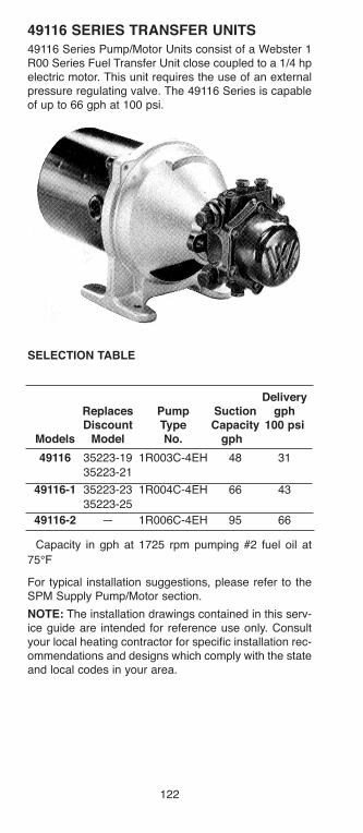
49116 SERIES TRaNSfER UNITS49116 Series Pump/Motor Units consist of a Webster 1R00 Series Fuel Transfer Unit close coupled to a 1/4 hpelectric motor. This unit requires the use of an externalpressure regulating valve. The 49116 Series is capableof up to 66 gph at 100 psi.
SElECTION TablE
DeliveryReplaces Pump Suction gphDiscount Type Capacity 100 psi
Models Model No. gph � �
49116 35223-19 1R003C-4EH 48 31
35223-21
49116-1 35223-23 1R004C-4EH 66 43
35223-25
49116-2 — 1R006C-4EH 95 66
� Capacity in gph at 1725 rpm pumping #2 fuel oil at
75°F
For typical installation suggestions, please refer to theSPM Supply Pump/Motor section.
NOTE: The installation drawings contained in this serv-ice guide are intended for reference use only. Consultyour local heating contractor for specific installation rec-ommendations and designs which comply with the stateand local codes in your area.
122
h126818 Capital City Tools_LN6331 4/26/16 10:24 AM Page 122
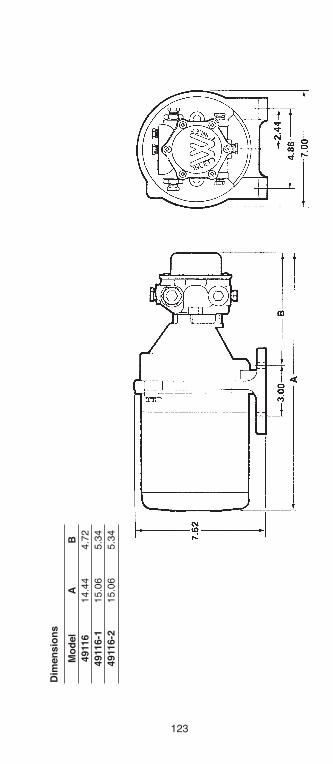
123
Dim
en
sio
ns
Mo
del
ab
4911
614.4
44.7
2
4911
6-1
15.0
65.3
4
4911
6-2
15.0
65.3
4
h126818 Capital City Tools_LN6331 4/26/16 10:24 AM Page 123

fUEl UNIT aCCESSORIES
MOUNTING aCCESSORIES
Webster oil heat product s are recommended for theirconvenience and ease of installation. Seven types ofmounting flanges, brackets, shaft sleeves and cou-plings are manufactured and stocked for use withWebster fuel units and pumps.
Complete dimension drawings are shown.
SElECTION TablE
Dimensions
Description Number
Hi-Foot Flange A45Q 1 Figure One
4 Bolt Adapter Flange For Standard HUB
(Nema 56C
Motor Mount) 41489 Figure Three
Horizontal
Mounting Flange A43Q7 Figure Four
Bell Housing 34330 Figure Five
Adapter For Has MTG EARS
B Pump 1100013 Figure Two
4 Bolt 56C Adapter 80316-1 Figure Six
Flange for Special 2 Bolt Pump MTG
34330
110001341489
A43Q7
A45Q180316-1
124
h126818 Capital City Tools_LN6331 4/26/16 10:24 AM Page 124

125
4.5
Figure Two-1100013
Figure Five-34330,48N Frame
Figure Four-A43Q7
Figure Six-80316 -1
h126818 Capital City Tools_LN6331 4/26/16 10:24 AM Page 125

OIl SafETY U/l® lISTED
ValVESOIl SafETY ValVESINSTallaTION INSTRUCTIONS
Webster OSV® valves can be used for the followingapplications which require slightly different installations:
1. Preventing tank siphoning and oil leaks in the eventof line breaks. (See Section “A”)
2. For use with a supply pump (booster pump) to pre-vent excessive pressure at the inlet of the burner fuelunit. (See Section “B”)
Many state and localcodes require a devicethat will automaticallyshut off the oil supplybefore it enters a build-ing should the linebetween the deviceand the burner be bro-ken. NFPA standardsrequire that the pres-sure at the burner fuelpumps must not exceed 3 PSI. The Webster OSV® sat-isfies both requirements when properly installed. Checklocal codes for any special requirements.
SECTION “a”
Using the OSV® valve to help prevent oil spills from bro-ken or corroded lines and fittings.
Operation
A recent Environmental Protection Agency sponsoredstudy found that most oil leaks are found in the pipingrather than the tank. Webster OSV® valves help preventoil spills by stopping oil flow in the event of line breakscaused by corroded lines or leaky fittings. The OSV® 9is mounted in the supply line as close as possible to thetank. Operation is simple. The OSV® requires a vacuumon its outlet side to open the valve and allow oil flow.When the burner is shut down, there is no vacuum fromthe fuel unit and the OSV® valve is closed—oil flow isstopped. When the burner starts up, vacuum from thefuel unit opens the OSV®, allowing oil to flow.If a corroded broken line or a loose fitting causes a leakto develop between the OSV® and burner, air enters theline. Fuel unit vacuum is reduced and the OSV® will notopen, preventing tank siphoning and a major spill.
bIO OIl SafETY ValVE UPGRaDEOSV38 and OSV50Webster currently has an Oil Safety Valve for Bio andWaste Oil applications. This valve is U/L listed for BioFuel and is compatible with a wide range of other fuelssuch as B20-B100, #1-#2 Fuel Oil, Diesel, Kerosene andWaste Oil, with a Temperature Range of -40 to 140ºF.
126
h126818 Capital City Tools_LN6331 4/26/16 10:24 AM Page 126

127
INSTallaTION
The OSV® should be mounted on the supply line asclose to the tank as possible.
CaUTION: DO NOT mount the OSV® more than threefeet above the fuel unit inlet or more than three feetabove the lowest point in the fuel line connecting theOSV® to the burner fuel unit.
See Figures 1 & 2 below.
figure 2. Mobile Home Gravity System
Failure to observe the above caution will compromisevalve action and may result in tank siphoning action inthe event of a line failure between tank and burner.
TROUblESHOOTING
The OSV® valve will not open during fuel unit operationif there is any air leak in the system between OSV® andburner that prevents development of the operationalvacuum required. (See Table 1).
If there is no oil flow to burner or prime is lost
A. Check to see if OSV® valve is stopping oil flow. Turnon burner and manually depress OSV® diaphragmplate with paper clip to see if burner fires up.
h126818 Capital City Tools_LN6331 4/26/16 10:24 AM Page 127
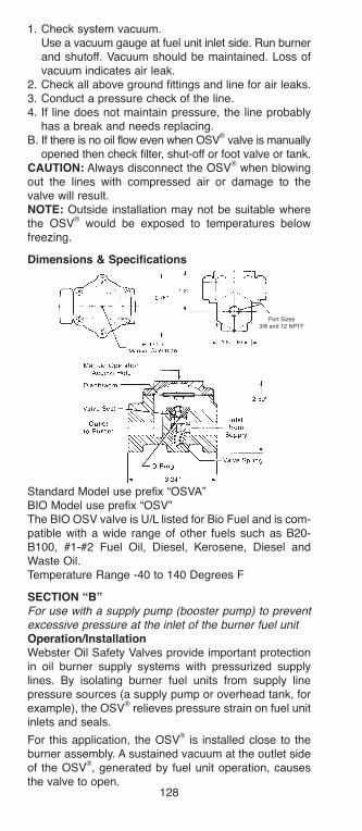
1. Check system vacuum.Use a vacuum gauge at fuel unit inlet side. Run burner and shutoff. Vacuum should be maintained. Loss of vacuum indicates air leak.
2. Check all above ground fittings and line for air leaks.3. Conduct a pressure check of the line.4. If line does not maintain pressure, the line probably
has a break and needs replacing.B. If there is no oil flow even when OSV
®valve is manually
opened then check filter, shut-off or foot valve or tank.CaUTION: Always disconnect the OSV
®when blowing
out the lines with compressed air or damage to thevalve will result.NOTE: Outside installation may not be suitable wherethe OSV
®would be exposed to temperatures below
freezing.
Dimensions & Specifications
Standard Model use prefix “OSVA”BIO Model use prefix “OSV”The BIO OSV valve is U/L listed for Bio Fuel and is com-patible with a wide range of other fuels such as B20-B100, #1-#2 Fuel Oil, Diesel, Kerosene, Diesel andWaste Oil.Temperature Range -40 to 140 Degrees F
SECTION “b”For use with a supply pump (booster pump) to preventexcessive pressure at the inlet of the burner fuel unitOperation/InstallationWebster Oil Safety Valves provide important protectionin oil burner supply systems with pressurized supplylines. By isolating burner fuel units from supply linepressure sources (a supply pump or overhead tank, forexample), the OSV
®relieves pressure strain on fuel unit
inlets and seals.
For this application, the OSV®
is installed close to theburner assembly. A sustained vacuum at the outlet sideof the OSV
®, generated by fuel unit operation, causes
the valve to open.
Port Sizes3/8 and 12 NPTF
128
h126818 Capital City Tools_LN6331 4/26/16 10:24 AM Page 128
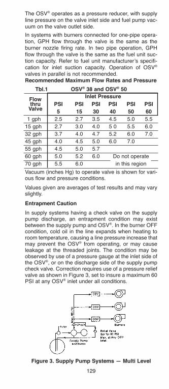
129
The OSV® operates as a pressure reducer, with supplyline pressure on the valve inlet side and fuel pump vac-uum on the valve outlet side.
In systems with burners connected for one-pipe opera-tion, GPH flow through the valve is the same as theburner nozzle firing rate. In two pipe operation, GPHflow through the valve is the same as the fuel unit suc-tion capacity. Refer to fuel unit manufacturer’s specifi-cation for inlet suction capacity. Operation of OSV®
valves in parallel is not recommended.Recommended Maximum flow Rates and Pressure
Tbl.1 OSV® 38 and OSV® 50
PSI PSI PSI PSI PSI PSI
5 15 30 40 50 60
1 gph 2.5 2.7 3.5 4.5 5.0 5.5
15 gph 2.7 3.0 4.0 5 0 5.5 6.0
32 gph 3.7 4.0 4.7 5.2 6.0 7.0
45 gph 4.0 4.5 5.0 6.0 7.0
55 gph 4.5 5.0 5.7
60 gph 5.0 5.2 6.0 Do not operate
70 gph 5.5 6.0 in this region
Vacuum (inches Hg) to operate valve is shown for vari-ous flow and pressure conditions.
Values given are averages of test results and may varyslightly.
Entrapment Caution
In supply systems having a check valve on the supplypump discharge, an entrapment condition may existbetween the supply pump and OSV®. In the burner OFFcondition, cold oil in the line expands when heating toroom temperature, causing a line pressure increase thatmay prevent the OSV® from operating, or may causeleakage at the threaded joints. The condition may beobserved by use of a pressure gauge at the inlet side ofthe OSV®, or on the discharge side of the supply pumpcheck valve. Correction requires use of a pressure reliefvalve as shown in Figure 3, set to insure a maximum 60PSI at any OSV® inlet under all conditions.
figure 3. Supply Pump Systems — Multi level
Inlet Pressureflowthru
Valve
h126818 Capital City Tools_LN6331 4/26/16 10:24 AM Page 129

OPEN lOOP SYSTEM
To insure a flooded supply line, a standpipe before thejunction of the supply line with the return line is required.The standpipe on the supply line must be at least threefeet higher than any point in the supply line systembefore joining the return line. Use of a Webster 48598vacuum breaker is recommended.
figure 4. Central Supply Systems tor Mobile HomesGENERal CONSIDERaTIONS
PORTING CONNECTIONS
The OSV® valve is installed in the supply line betweenthe tank and burner. Its location depends on the appli-cation (see sections A & B). The OSV® “IN” port is con-nected to the tank side. The OSV® “OUT” port is con-nected to the burner side of the line. Non hardeningpipe dope is recommended for use on the fittingthreads. Do not use teflon tape, as it may void all war-ranties.
MOUNTING
The OSV® can be mounted in any position. In thoseenvironments where dirt or moisture is particularly aproblem, the preferred position is with the cover down.This allows any moisture from the diaphragm area todrain out the manual access hole.
fIlTER
A dependable in-line filter is recommended between thetank and OSV® to help assure optimum valve perform-ance. Dirt on the valve seat area could prevent thevalve from sealing tightly.
PRIMING
For priming purposes, the OSV®
can be manually oper-ated by inserting a paper clip or stiff wire through themanual access hole, and depressing the diaphragmplate. Remove the wire immediately if oil appears at thefuel unit vent, the burner fires up, or there is any sign ofoil at the burner fuel unit.
CHECK lOCal CODES
The installer is responsible for complying with all appli-cable codes. Typical installation diagrams are shown forreference only.
130
h126818 Capital City Tools_LN6331 4/26/16 10:24 AM Page 130
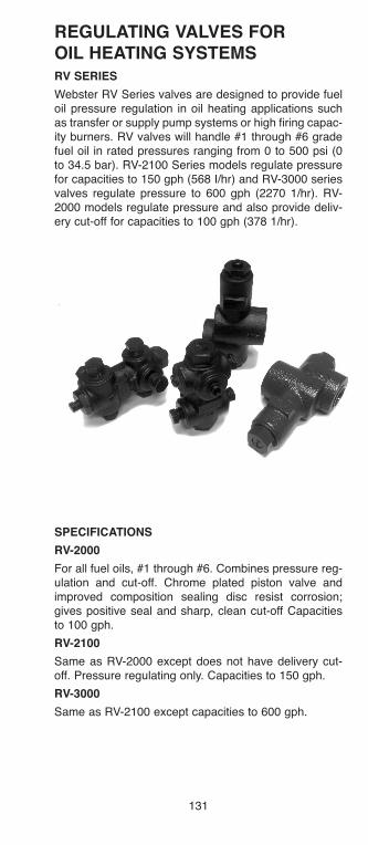
131
REGUlaTING ValVES fOROIl HEaTING SYSTEMSRV SERIES
Webster RV Series valves are designed to provide fueloil pressure regulation in oil heating applications suchas transfer or supply pump systems or high firing capac-ity burners. RV valves will handle #1 through #6 gradefuel oil in rated pressures ranging from 0 to 500 psi (0to 34.5 bar). RV-2100 Series models regulate pressurefor capacities to 150 gph (568 I/hr) and RV-3000 seriesvalves regulate pressure to 600 gph (2270 1/hr). RV-2000 models regulate pressure and also provide deliv-ery cut-off for capacities to 100 gph (378 1/hr).
SPECIfICaTIONS
RV-2000
For all fuel oils, #1 through #6. Combines pressure reg-ulation and cut-off. Chrome plated piston valve andimproved composition sealing disc resist corrosion;gives positive seal and sharp, clean cut-off Capacitiesto 100 gph.
RV-2100
Same as RV-2000 except does not have delivery cut-off. Pressure regulating only. Capacities to 150 gph.
RV-3000
Same as RV-2100 except capacities to 600 gph.
h126818 Capital City Tools_LN6331 4/26/16 10:24 AM Page 131

132
dimensions
RV-3000
RV-2000
RV-2100
h126818 Capital City Tools_LN6331 4/26/16 10:24 AM Page 132
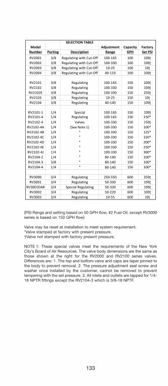
133
SELECTION TABLEModel Adjustment Capacity Factory
Number Porting Description Range GPH Set PSIRV2001 3/8 Regulating with Cut-Off 100-165 100 100RV2002 3/8 Regulating with Cut-Off 100-330 100 100RV2003 3/8 Regulating with Cut-Off 10-25 100 10RV2004 3/8 Regulating with Cut-Off 40-110 100 100
RV2101 3/8 Regulating 100-165 150 100RV2102 3/8 Regulating 100-330 150 100
RV2102E 3/8 Regulating 100-330 150 250RV2103 3/8 Regulating 10-25 150 10RV2104 3/8 Regulating 40-140 150 100
RV2101-1 1/4 Special 100-165 150 100RV2101-4 1/4 Regulating 100-165 150 150*RV2102-4 1/4 Valves 100-330 150 150
RV2102-4A 1/4 (See Note 1) 100-330 150 100*RV2102-4B 1/4 " 100-330 150 125*RV2102-4C 1/4 " 100-330 150 150*RV2102-4D 1/4 " 100-330 150 200*RV2102-4E 1/4 " 100-330 150 250*RV2102-4J 1/4 " 100-330 150 300*RV2104-2 1/4 " 80-140 150 100*RV2104-3 3/8 " 80-140 150 100*RV2104-4 1/4 " 80-40 150 100*
RV3000 3/4 Regulating 250-550 600 250RV3001 3/4 Regulating 50-330 600 100
RV3001DAR 3/4 Special Regulating 50-330 600 100RV3002 3/4 Regulating 50-220 600 100RV3003 3/4 Regulating 10-55 600 10
80-140
(PSI Range and setting based on 50 GPH flow, #2 Fuel Oil, except RV3000series is based on 150 GPH flow)
Valve may be reset at installation to meet system requirement.*Valve stamped at factory with present pressure.†Valve not stamped with factory present pressure.
NOTE 1: These special valves meet the requirements of the New YorkCity’s Board of Air Resources. The valve body dimensions are the same asthose shown at the right for the RV2000 and RV2100 series valves.Differences are: 1. The top and bottom valve and caps are taper pinned tothe body to prevent removal. 2. The pressure adjustment seal screw andwasher once installed by the customer, cannot be removed to preventtempering with the set pressure. 3. All inlets and outlets are tapped for 1/4-18 NPTR fittings except the RV2104-3 which is 3/8-18 NPTF.
h126818 Capital City Tools_LN6331 4/26/16 10:24 AM Page 133
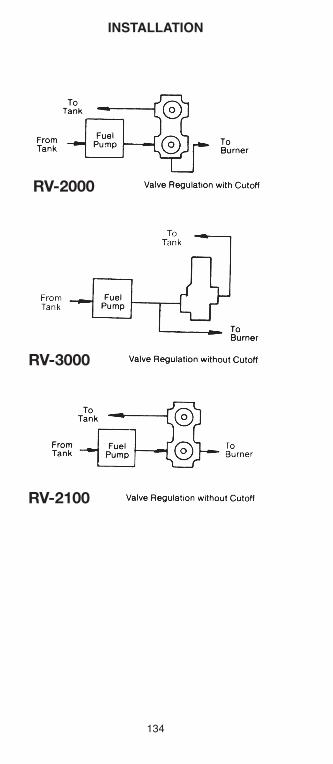
INSTallaTION
134
RV-2000
RV-3000
RV-2100
h126818 Capital City Tools_LN6331 4/26/16 10:24 AM Page 134

135
Relief Valve Installation
ToTank
Pressure Pressure
ToTank
RV-2000
The RV-2000 series regulating valves can also be usedas a relief valve. Designed to provide system pressurerelief for #1 through #6 fuel grades and for rated pres-sure ranges from 0 to 500 psi at 150 gph or less. The following adjustment ranges are available:10-25 psi use RV-200340-110 psi use RV-2004100-330 psi use RV-2002
h126818 Capital City Tools_LN6331 4/26/16 10:24 AM Page 135

INSTallaTION DaTa
2’ to 4’
VaCUUM bREaKER (48598)Incorporates Viton “O” Ring seat, 3/8-18 NPTF ports.Can be used as a suction line check valve.
136
h126818 Capital City Tools_LN6331 4/26/16 10:24 AM Page 136

137
TroubleshootingGENERAL PUMP PROBLEMS
• Noisy pump
• Pump will not prime
• Rumble coming from burner at start-up
• Oil leaking from pump cover gasket or blown cover gasket
• Pump looses prime after an extended shutdown
• Vacuum coming from return port on oil pump (two pipe installation)
• Pump seizes at start-up, blows seal, damage todischarge pressure gauge
• Supply unit does not run
• Unit runs but no oil reaches supply pump
• Unit supplies oil to distribution system, but nodelivery of oil at OSV valves
• Oil delivery at OSV valves, but burners do not fire
• Burner pump seal damaged
• Pressure increases in supply line after shutdown
• Oil Safety Valve does not open
Noisy pump
Check for air leaks
Check for high vacuum condition, (10 in. for singlestage and 15 in. for two stage pumps)
Pump will not prime
Measure suction inlet vacuum, should not exceed15 in. of vacuum
Check that all plugs and suction line connections areairtight
Be certain by-pass plug is in position on two pipeinstallation
Use adequate size suction line
Be certain suction line filter or strainer has adequatecapacity
Rumble coming from burner at start-up
Check cutoff at pump or external solenoid
Oil leaking from pump cover gasket(s) blown covergasket(s)
Check for correct pump rotation
Pump looses prime after an extended shutdown
Check all pipe connections for air leaks
Return line not submersed in oil
In supply pump applications the return loop mayneed a vacuum breaker installed to prevent siphoning
h126818 Capital City Tools_LN6331 4/26/16 10:24 AM Page 137

Vacuum coming from return port on oil pump(two pipe installation)
By-pass plug not installed
If by-pass plug is installed check for blockedsuction line
Pump seizes at start-up. blows seal. damageto discharge pressure gauge
Check for blocked return line or drain port from pump
By-pass plug should be removed on single pipeinstallation
SUPPlY PUMP PROblEMS
Supply Unit does not run
Check motor electrical connections
Check for obstruction in return line such as a reversedcheck valve
Check circuit breaker and correct possible overload
Unit runs. but no oil reaches supply pump
Measure suction inlet vacuum, should not exceed 15 in. of vacuum
Check that all plugs and suction line connections areairtight
Be certain by-pass plug is in position
Use adequate size suction line
Be certain suction line filter or strainer has adequatecapacity
Unit supplies oil to distribution system, but no deliveryof oil at OSV valves
Confirm specified unit can provide needed vertical discharge pressure
Check that all supply line connections are air andoil tight
Use adequate size supply line
Minimize supply line restrictions
Prime pump and purge supply lines of air
Check pump pressure settings
Oil delivery at OSV valves. but burners do not fire
Confirm specified unit can provide needed capacity(Size to firing rate for single pipe burners or size togear set capacity for two piped burners)
In pressurized system, adjust pressure to develop areading of 10-15 PSI at the most remote or highestburner
138
h126818 Capital City Tools_LN6331 4/26/16 10:24 AM Page 138
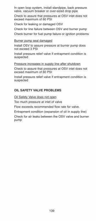
139
In open loop system, install standpipe, back pressurevalve, vacuum breaker or over-sized drop pipe
Check to assure that pressures at OSV inlet does notexceed maximum of 60 PSI
Check for leaking or damaged OSV
Check for line failure between OSV and burner pump
Check burner for fuel pump failure or ignition problems
Burner pump seal damaged
Install OSV to assure pressure at burner pump doesnot exceed 3 PSI
Install pressure relief valve if entrapment condition issuspected
Pressure increases in supply line after shutdown
Check to assure that pressures at OSV inlet does notexceed maximum of 60 PSI
Install pressure relief valve if entrapment condition issuspected
OIl SafETY ValVE PROblEMS
Oil Safety Valve does not open
Too much pressure at inlet of valve
Flow exceeds recommended flow rate for valve.
Entrapment condition (expansion of oil in supply line)
Check for air leaks between the OSV valve and burnerpump
h126818 Capital City Tools_LN6331 4/26/16 10:24 AM Page 139

MaNUfaCTURERS REPSWebster and its Representatives have the resourcesand technical background to answer any installation orservice questions you may have.
Please refer to the listing below for the WebsterRepresentative near you.
SHaNE MIllER STATESG. MIllER CO. IN / Il / MN / WI901 River Lane KY / ND / SDLoves Park, IL 61111Tele: 815-964-5692 Fax: 815-964-5770Cell: [email protected]
MONS KING STATESETC SalES, INC. DE / MD / VaPO Box 235 E.Pa / NjPaoli, PA 19301Tele: 610-296-3527 Fax: 610-640-4271Cell: [email protected]
TOM jOHNS STATESTRaDREP lTD OH / WV / W.Pa / MI3801 Wiltshire RoadChagrin Falls, OH.Tele: 440-247-3880 Fax: [email protected]
lENNIE DeaNGElO STATESPIlGRIM SalES ME / NH / Ma18 Pilgrim Road CT / VT / RIMarblehead, MA 01945Cell: 617-548-2813 Fax: [email protected]
GEORGE NIKIfOROV, INC INTERNaTIONal200 Park Ave., SouthSuite 514New York, NY 10003Tele: 212-473-4555 Fax: [email protected]
DON KNUTH STATESCC Marketing NY61 Pennsylvania Ave.Apalachin, NY 13732Tele: 518-882-5201 Fax: [email protected]
bIll GlUCKIN lONG ISlaND, NYCOMfORT ZONE SalES2870 Milburn Ave.Baldwin, NY 11510Tele: 516-442-0388 Fax: 516-442-0389Cell: [email protected]
140
h126818 Capital City Tools_LN6331 4/26/16 10:24 AM Page 140
141
CURTIS ZaHalKa INSIDE SalESWEbSTER fUEl PUMPS & ValVES219 Hahn RoadFrankfort, KY 40601Tele: 502-223-0025 Fax: 502-223-5629Toll Free: [email protected]@cctoolinc.com
E.S. GallaGHER SalES CaNaDa920 Caledonia RoadUnit 3BToronto, Ontario M6B 3Y1Tele: 416-789-5385 Fax: [email protected]
www.esgallagher.com
h126818 Capital City Tools_LN6331 4/26/16 10:24 AM Page 141

142
NOTES
h126818 Capital City Tools_LN6331 4/26/16 10:24 AM Page 142