Embed Size (px)
Citation preview
Fuel Injection and Spray Research Using X-Ray Diagnostics
Project ID ACE10
Christopher Powell
Argonne National Laboratory
VT Annual Merit Review 15 May 2012
Crystal City, VA
Team Leader: Gurpreet Singh This presentation does not contain any proprietary, confidential, or
otherwise restricted information
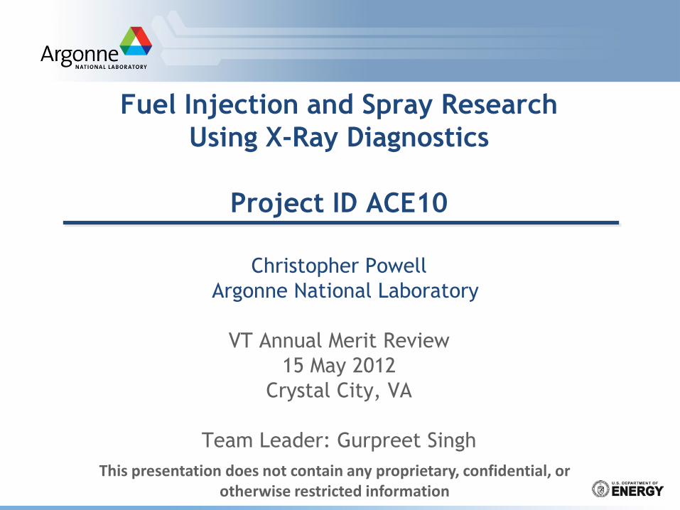
Overview
2
Timeline
Budget
Barriers
Partners
FY2011: $1100K FY2012: $825K + 175K
Engine Combustion Network, Delphi Diesel, Westport, Chrysler, Air Force Research Lab
“Inadequate understanding of the fundamentals of fuel injection”
“Inadequate capability to simulate this process”
“The capability to accurately model and simulate the complex fuel and air flows”
Project Start: FY2000
Objectives of this Research
3
■ Improve the fundamental understanding of fuel injection and sprays
■ Assist in development of improved spray models using unique quantitative measurements of sprays
■ Support industrial partners by giving them access to unique injector and spray diagnostics
Fuel injection is a significant barrier to improving efficiency and emissions
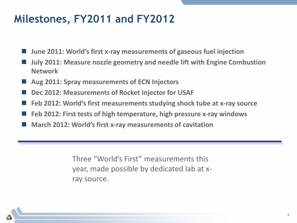
Milestones, FY2011 and FY2012
4
June 2011: World’s first x-ray measurements of gaseous fuel injection July 2011: Measure nozzle geometry and needle lift with Engine Combustion
Network Aug 2011: Spray measurements of ECN Injectors Dec 2012: Measurements of Rocket Injector for USAF Feb 2012: World’s first measurements studying shock tube at x-ray source Feb 2012: First tests of high temperature, high pressure x-ray windows March 2012: World’s first x-ray measurements of cavitation
Three “World’s First” measurements this year, made possible by dedicated lab at x-ray source.
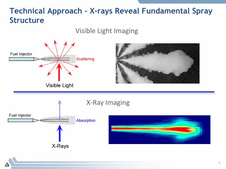
Technical Approach – X-rays Reveal Fundamental Spray Structure
5
Visible Light Imaging
X-Ray Imaging
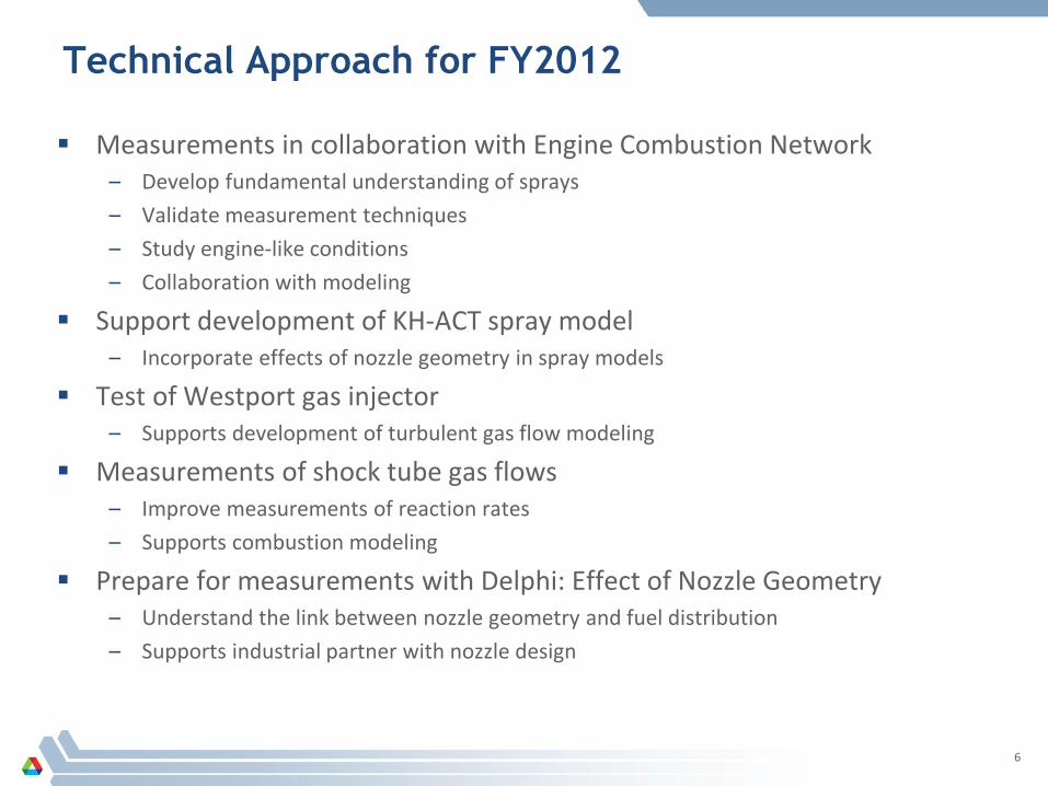
Technical Approach for FY2012
Measurements in collaboration with Engine Combustion Network – Develop fundamental understanding of sprays – Validate measurement techniques – Study engine-like conditions – Collaboration with modeling
Support development of KH-ACT spray model – Incorporate effects of nozzle geometry in spray models
Test of Westport gas injector – Supports development of turbulent gas flow modeling
Measurements of shock tube gas flows – Improve measurements of reaction rates – Supports combustion modeling
Prepare for measurements with Delphi: Effect of Nozzle Geometry – Understand the link between nozzle geometry and fuel distribution – Supports industrial partner with nozzle design
6
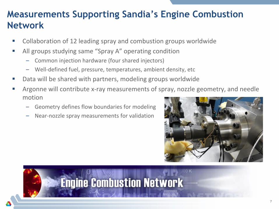
Measurements Supporting Sandia’s Engine Combustion Network
Collaboration of 12 leading spray and combustion groups worldwide All groups studying same “Spray A” operating condition
– Common injection hardware (four shared injectors) – Well-defined fuel, pressure, temperatures, ambient density, etc
Data will be shared with partners, modeling groups worldwide Argonne will contribute x-ray measurements of spray, nozzle geometry, and needle
motion – Geometry defines flow boundaries for modeling – Near-nozzle spray measurements for validation
7
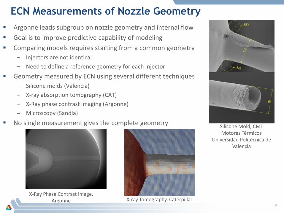
ECN Measurements of Nozzle Geometry Argonne leads subgroup on nozzle geometry and internal flow Goal is to improve predictive capability of modeling Comparing models requires starting from a common geometry
– Injectors are not identical – Need to define a reference geometry for each injector
Geometry measured by ECN using several different techniques – Silicone molds (Valencia) – X-ray absorption tomography (CAT) – X-Ray phase contrast imaging (Argonne) – Microscopy (Sandia)
No single measurement gives the complete geometry
8 X-ray Tomography, Caterpillar
Silicone Mold, CMT Motores Térmicos
Universidad Politécnica de Valencia
X-Ray Phase Contrast Image, Argonne
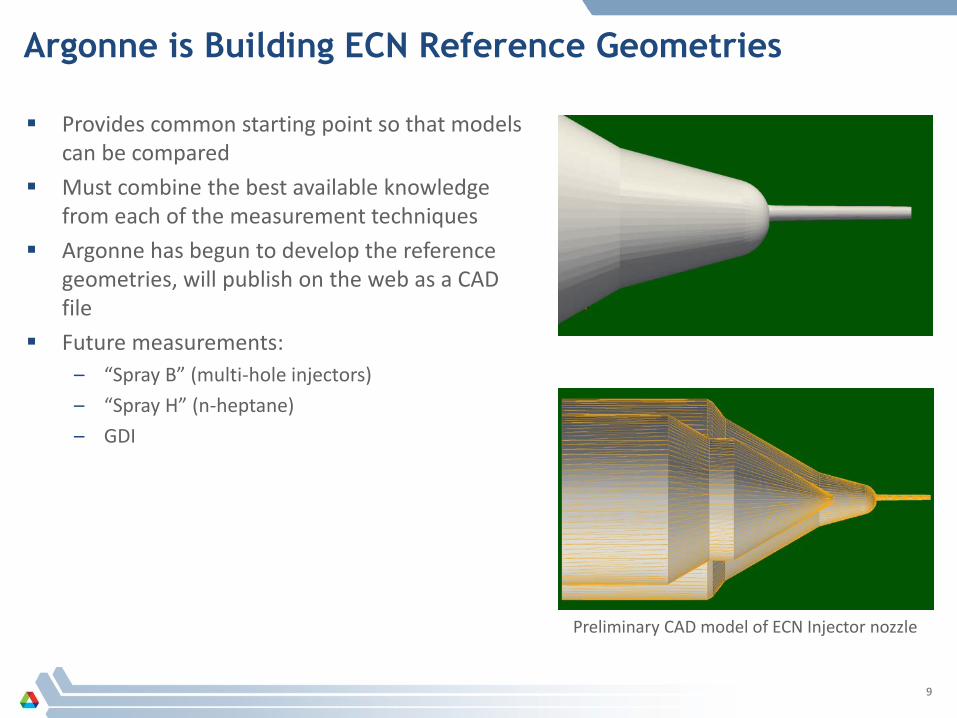
Argonne is Building ECN Reference Geometries
9
Provides common starting point so that models can be compared
Must combine the best available knowledge from each of the measurement techniques
Argonne has begun to develop the reference geometries, will publish on the web as a CAD file
Future measurements: – “Spray B” (multi-hole injectors) – “Spray H” (n-heptane) – GDI
Preliminary CAD model of ECN Injector nozzle

X-Ray Measurements of Fuel Distribution from ECN Injectors
Similarities: All elliptical Relatively dense core Same total mass in cross
section
10
Nozzle 210675 Nozzle 210678 Nozzle 210679
Differences: Orientation of the ellipse Fraction of fuel in the core
(20-40%) Peak density value
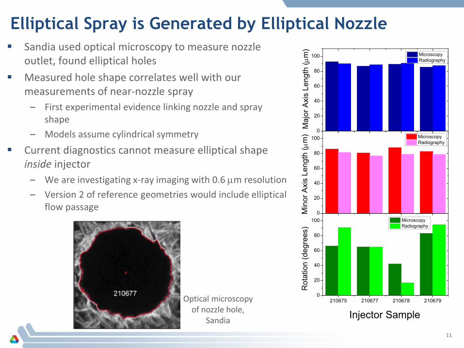
Elliptical Spray is Generated by Elliptical Nozzle Sandia used optical microscopy to measure nozzle
outlet, found elliptical holes Measured hole shape correlates well with our
measurements of near-nozzle spray – First experimental evidence linking nozzle and spray
shape – Models assume cylindrical symmetry
Current diagnostics cannot measure elliptical shape inside injector
– We are investigating x-ray imaging with 0.6 µm resolution – Version 2 of reference geometries would include elliptical
flow passage
11
0
20
40
60
80
100
Maj
or A
xis
Leng
th (µ
m)
Microscopy Radiography
0
20
40
60
80
100
Min
or A
xis
Leng
th (µ
m) Microscopy
Radiography
210675 210677 210678 2106790
20
40
60
80
100
Rot
atio
n (d
egre
es)
Injector Sample
Microscopy Radiography
Optical microscopy of nozzle hole,
Sandia
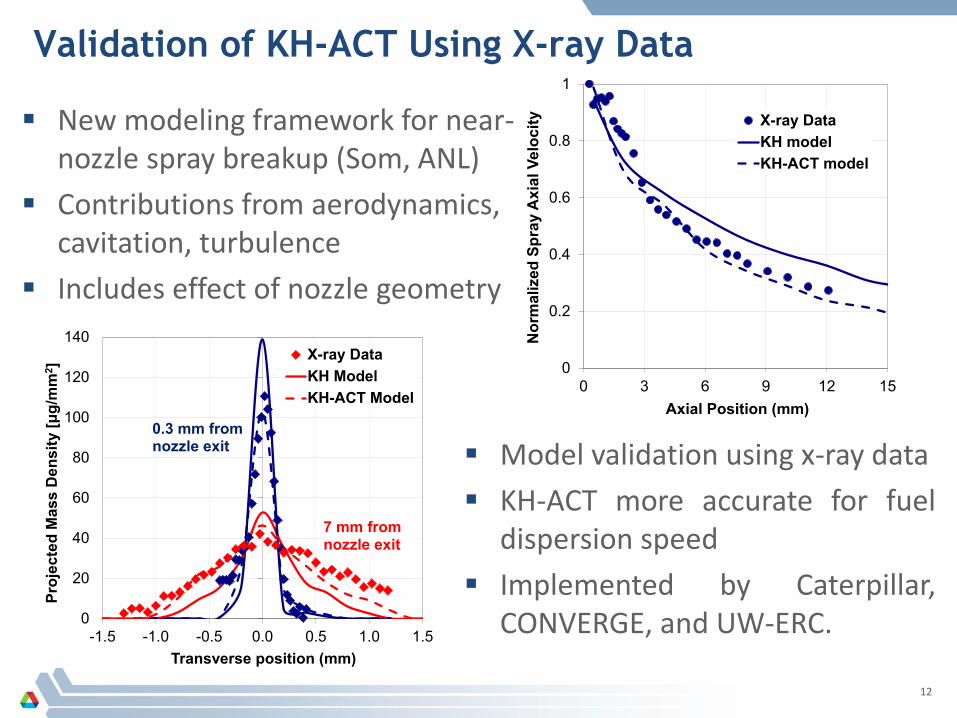
Validation of KH-ACT Using X-ray Data
12
Model validation using x-ray data KH-ACT more accurate for fuel
dispersion speed Implemented by Caterpillar,
CONVERGE, and UW-ERC.
0
0.2
0.4
0.6
0.8
1
0 3 6 9 12 15
Nor
mal
ized
Spr
ay A
xial
Vel
ocity
Axial Position (mm)
X-ray DataKH modelKH-ACT model
0
20
40
60
80
100
120
140
-1.5 -1.0 -0.5 0.0 0.5 1.0 1.5
Proj
ecte
d M
ass
Den
sity
[μg/
mm
2 ]
Transverse position (mm)
X-ray DataKH ModelKH-ACT Model
7 mm from nozzle exit
0.3 mm from nozzle exit
New modeling framework for near-nozzle spray breakup (Som, ANL)
Contributions from aerodynamics, cavitation, turbulence
Includes effect of nozzle geometry
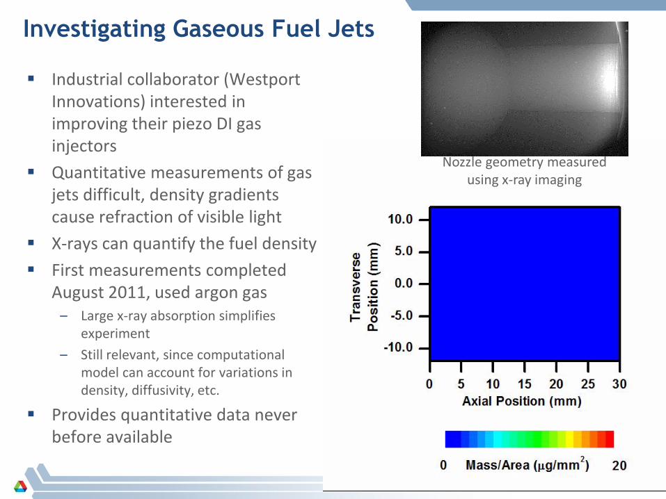
Investigating Gaseous Fuel Jets
Industrial collaborator (Westport Innovations) interested in improving their piezo DI gas injectors
Quantitative measurements of gas jets difficult, density gradients cause refraction of visible light
X-rays can quantify the fuel density First measurements completed
August 2011, used argon gas – Large x-ray absorption simplifies
experiment – Still relevant, since computational
model can account for variations in density, diffusivity, etc.
Provides quantitative data never before available
13
Nozzle geometry measured using x-ray imaging
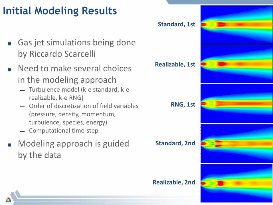
Initial Modeling Results Standard, 1st
Realizable, 1st
RNG, 1st
Standard, 2nd
Realizable, 2nd
■ Gas jet simulations being done by Riccardo Scarcelli
■ Need to make several choices in the modeling approach ▬ Turbulence model (k-e standard, k-e
realizable, k-e RNG) ▬ Order of discretization of field variables
(pressure, density, momentum, turbulence, species, energy)
▬ Computational time-step
■ Modeling approach is guided by the data
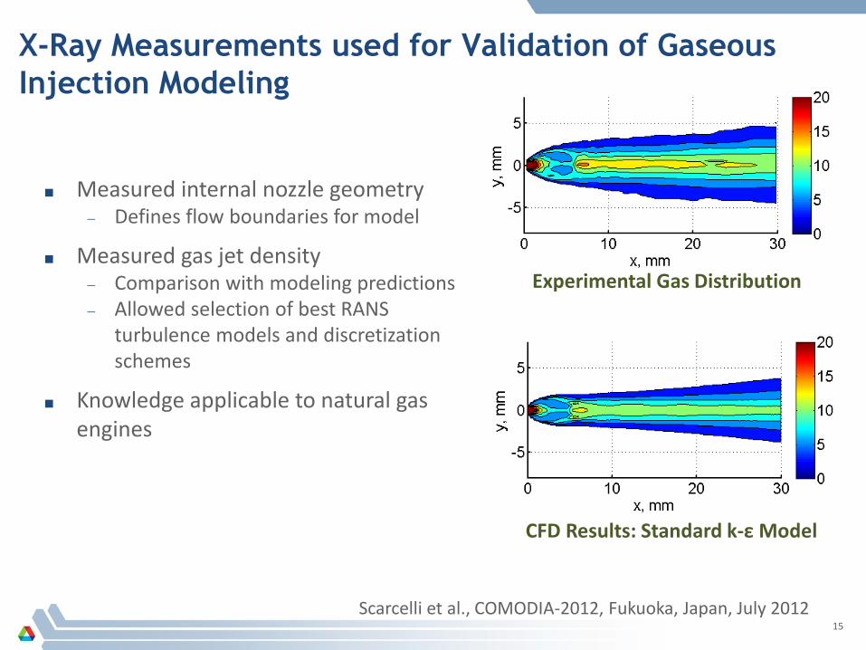
X-Ray Measurements used for Validation of Gaseous Injection Modeling
15
Experimental Gas Distribution
CFD Results: Standard k-ε Model
■ Measured internal nozzle geometry − Defines flow boundaries for model
■ Measured gas jet density − Comparison with modeling predictions − Allowed selection of best RANS
turbulence models and discretization schemes
■ Knowledge applicable to natural gas engines
Scarcelli et al., COMODIA-2012, Fukuoka, Japan, July 2012

X-ray Studies of Shock Tube Prototype
16
Argonne collaboration “Bridging the Gap” between fundamental combustion (Chemistry) and IC engines (Transportation)
Argonne chemistry (DOE-BES) has developed a “Baby Shock Tube” for measuring combustion using x-ray diagnostics
+ Fast cycle time (up to 4 Hz), very reproducible, wide operating range
+ Allows data to be averaged for high S/N – Small diameter, large boundary layer effects
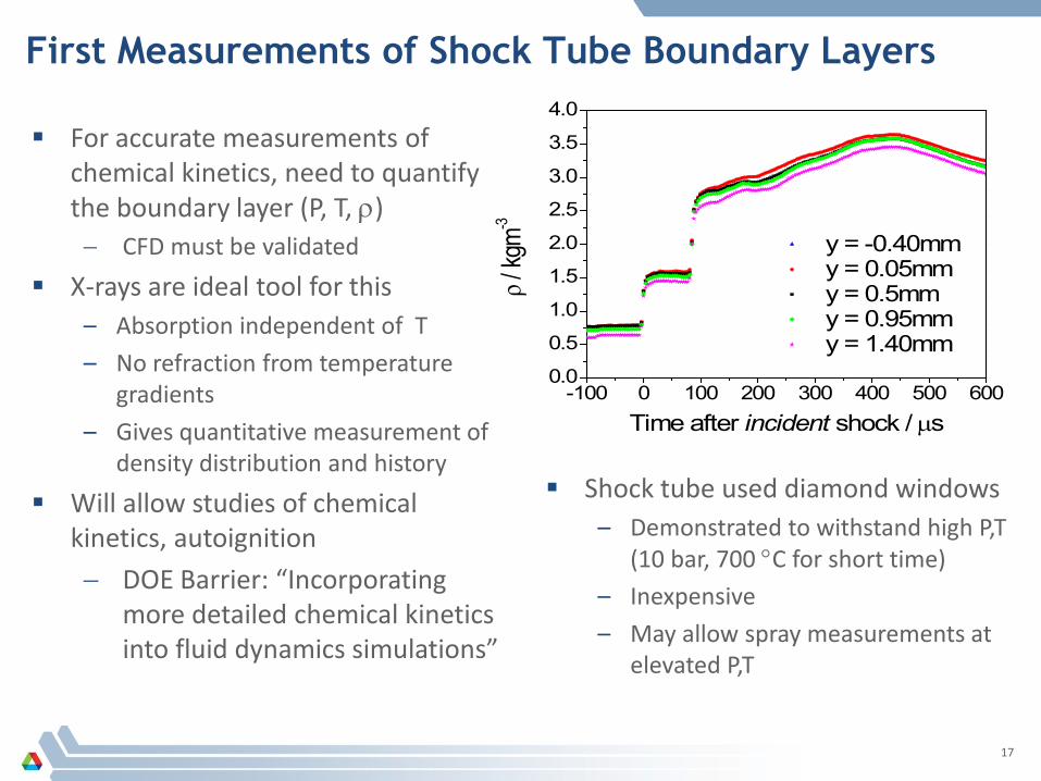
First Measurements of Shock Tube Boundary Layers
17
-100 0 100 200 300 400 500 6000.0
0.5
1.0
1.5
2.0
2.5
3.0
3.5
4.0
y = -0.40mm y = 0.05mm y = 0.5mm y = 0.95mm y = 1.40mm
ρ / kg
m-3
Time after incident shock / µs
For accurate measurements of chemical kinetics, need to quantify the boundary layer (P, T, ρ) − CFD must be validated
X-rays are ideal tool for this – Absorption independent of T – No refraction from temperature
gradients – Gives quantitative measurement of
density distribution and history Will allow studies of chemical
kinetics, autoignition − DOE Barrier: “Incorporating
more detailed chemical kinetics into fluid dynamics simulations”
Shock tube used diamond windows – Demonstrated to withstand high P,T
(10 bar, 700 °C for short time) – Inexpensive – May allow spray measurements at
elevated P,T
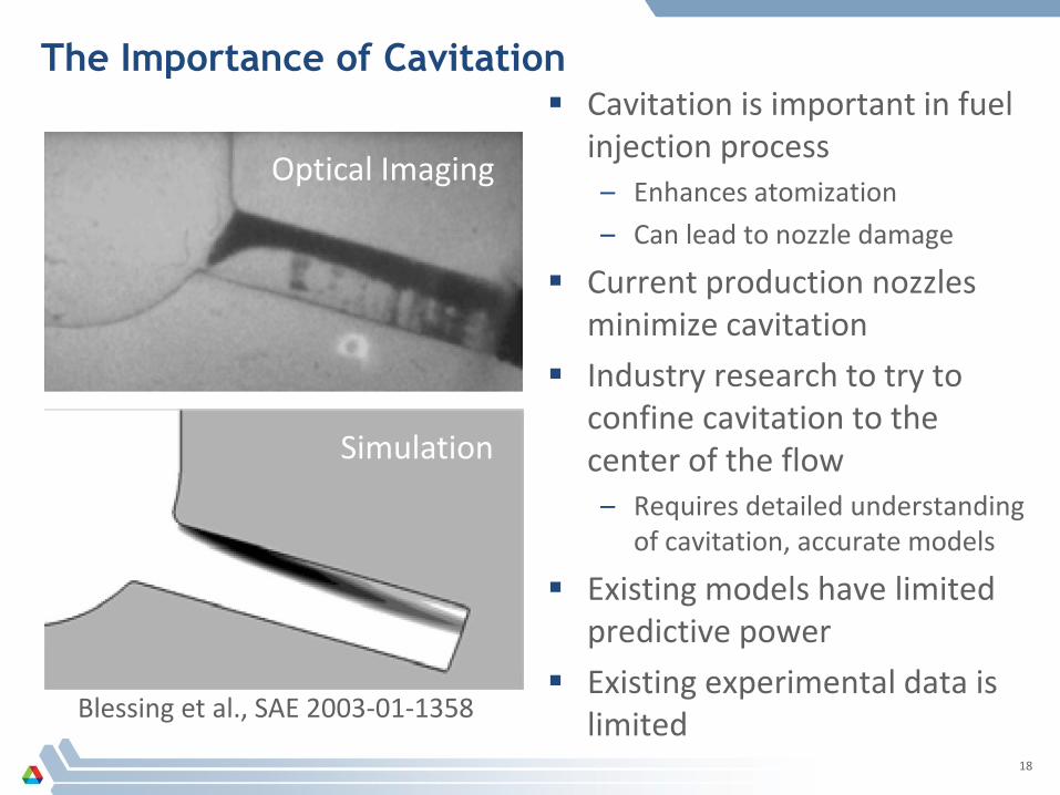
The Importance of Cavitation Cavitation is important in fuel
injection process – Enhances atomization – Can lead to nozzle damage
Current production nozzles minimize cavitation
Industry research to try to confine cavitation to the center of the flow – Requires detailed understanding
of cavitation, accurate models
Existing models have limited predictive power
Existing experimental data is limited
18
Blessing et al., SAE 2003-01-1358
Optical Imaging
Simulation
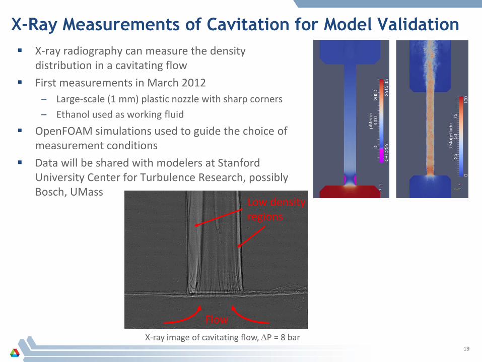
X-Ray Measurements of Cavitation for Model Validation X-ray radiography can measure the density
distribution in a cavitating flow First measurements in March 2012
– Large-scale (1 mm) plastic nozzle with sharp corners – Ethanol used as working fluid
OpenFOAM simulations used to guide the choice of measurement conditions
Data will be shared with modelers at Stanford University Center for Turbulence Research, possibly Bosch, UMass
19
X-ray image of cavitating flow, ∆P = 8 bar
Low density regions
Flow
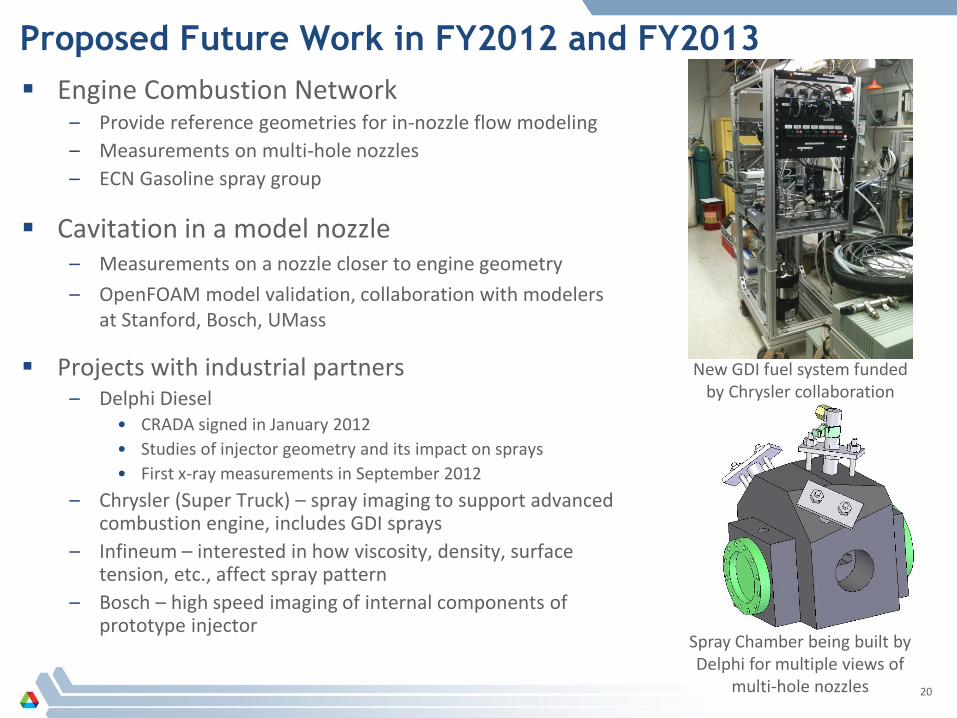
Proposed Future Work in FY2012 and FY2013 Engine Combustion Network
– Provide reference geometries for in-nozzle flow modeling – Measurements on multi-hole nozzles – ECN Gasoline spray group
Cavitation in a model nozzle – Measurements on a nozzle closer to engine geometry – OpenFOAM model validation, collaboration with modelers
at Stanford, Bosch, UMass
Projects with industrial partners – Delphi Diesel
• CRADA signed in January 2012 • Studies of injector geometry and its impact on sprays • First x-ray measurements in September 2012
– Chrysler (Super Truck) – spray imaging to support advanced combustion engine, includes GDI sprays
– Infineum – interested in how viscosity, density, surface tension, etc., affect spray pattern
– Bosch – high speed imaging of internal components of prototype injector
20
New GDI fuel system funded by Chrysler collaboration
Spray Chamber being built by Delphi for multiple views of
multi-hole nozzles
■ Improve the understanding of fuel injection and sprays − Collaboration with ECN, cavitation measurements
■ Assist in development of improved spray models − “Big unknowns”: turbulent fluid dynamics, chemical
kinetics, cavitation − Work on KH-ACT, gaseous injectors, ECN, cavitation
■ Support industrial partners − Westport, Delphi, Chrysler, AFRL
21
Summary
22
Technical Back-Up Slides (Note: please include this “separator” slide if you are including back-up technical slides (maximum of five).
These back-up technical slides will be available for your presentation and will be included in the DVD and Web
PDF files released to the public.)
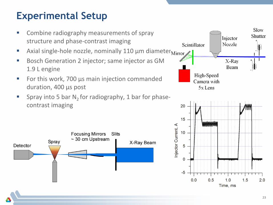
Experimental Setup
Combine radiography measurements of spray structure and phase-contrast imaging
Axial single-hole nozzle, nominally 110 µm diameter Bosch Generation 2 injector; same injector as GM
1.9 L engine For this work, 700 µs main injection commanded
duration, 400 µs post Spray into 5 bar N2 for radiography, 1 bar for phase-
contrast imaging
23
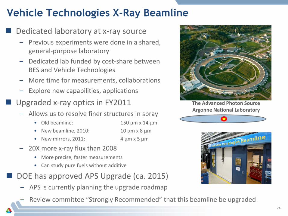
Vehicle Technologies X-Ray Beamline
Dedicated laboratory at x-ray source – Previous experiments were done in a shared,
general-purpose laboratory – Dedicated lab funded by cost-share between
BES and Vehicle Technologies – More time for measurements, collaborations – Explore new capabilities, applications
Upgraded x-ray optics in FY2011 – Allows us to resolve finer structures in spray
• Old beamline: 150 µm x 14 µm • New beamline, 2010: 10 µm x 8 µm • New mirrors, 2011: 4 µm x 5 µm
– 20X more x-ray flux than 2008 • More precise, faster measurements • Can study pure fuels without additive
24
DOE has approved APS Upgrade (ca. 2015) – APS is currently planning the upgrade roadmap
– Review committee “Strongly Recommended” that this beamline be upgraded
The Advanced Photon Source Argonne National Laboratory