Embed Size (px)
Citation preview
Jafarmadar, S., et al.: Numerical Studies of Spray Breakup in a Gasoline … THERMAL SCIENCE, Year 2011, Vol. 15, No. 4, pp. 1111-1122 1111
NUMERICAL STUDIES OF SPRAY BREAKUP IN A GASOLINE
DIRECT INJECTION ENGINE
by
Samad JAFARMADAR * and Vahied HEIDARPOOR
Department of Civil Engineering, Urmia Branch, Islamic Azad University, Urmia, Iran
Original scientific paper UDC: 621.43.038:519.23
DOI: 10.2298/TSCI101025047J
The objective of this study is to investigate the spray breakup process of sprays injected from single and two-hole nozzles for gasoline direct injection engines by using 3-D computational fluid dynamics code. Spray characteristics were ex-amined for spray tip penetration and other characteristics including: the vapor phase concentration distribution and droplet spatial distribution, which were ac-quired using the computational fluid dynamics simulation. Results showed that as the hole-axis-angle of two-hole nozzle decreased, the droplet coalescence in-creased and vapor mass decreased. The spray with cone angle of 5 deg. for sin-gle hole nozzle has the longest spray tip penetration and the spray with the hole--axis-angle of 30 deg. and spray cone angle of 30 deg. for two hole nozzles had the shortest one. Also, when the spray cone angle and hole-axis-angle increases from 5 to 30 deg., the Sauter mean diameter decreased for both single-hole and two-hole nozzles used in this study. For a single-hole nozzle, when spray cone angle increases from 5 to 30 deg., the vaporization rate increases very much be-cause of low level of coalescence. The result of model for tip penetration is good agreement with the corresponding experimental data in the literatures.
Key words: gasoline direct injection, spray, numerical simulation, hole-type nozzle
Introduction
In the last twenty years the fuel system of spark ignition (SI) engines has evolved
monotonically from carburetion to throttle-body injection, then to simultaneous-fire port-fuel
injection (PFI), and more recently to phased sequential-fire PFI. Advanced systems such as
variable valve-timing, multiple roller camshaft, computer algorithms for transient metering,
and turbo-charging have also been incorporated. But the current high-technology PFI engine,
although highly evolved, has nearly reached the limit of the potential since it still uses
throttling for load control and it still has a film of liquid fuel in the intake ports. The gasoline
direct injection (GDI), in theory, does not have these two limitations and offers many
opportunities for achieving significant improvements in engine fuel consumption and
emissions reductions [1, 2].
Gasoline PFI engines that are in production today have a higher brake specific fuel
consumption compared to the direct-injection (DI) Diesel engine. This is due to the higher
* Corresponding author; e-mail: [email protected]
Jafarmadar, S., et al.: Numerical Studies of Spray Breakup in a Gasoline … 1112 THERMAL SCIENCE, Year 2011, Vol. 15, No. 4, pp. 1111-1122
compression ratio and the unthrottled operation typical of Diesel engines, that, however, have
higher NOx and soot emissions, slightly higher noise level and lower startability. The ideal
would be to put together the best features of the both combining Diesel efficiency with
gasoline specific power. Studies in this direction have shown that this may be achieved with
GDI unthrottled engine. Fuel is injected directly into the combustion chamber in order to have
a mixture with an ignitable composition near the spark plug at the time of ignition for all
loads.
In a GDI engine, the fuel is injected directly into the cylinder avoiding the problems
related with fuel film in the port. However this does not guarantee that fuel film problems are
absent: the wetting of the piston crown or other combustion chamber surfaces, whether
intentional or not, may occur. The mass delivered into the cylinder is more accurately
controlled, providing potential for leaner combustion and less cycle-to-cycle variations. GDI
engines require much less fuel to start leading to reductions in HC spikes during transient
operations that could approach the level observed for steady operating conditions [3]. Other
advantages of the GDI are the fuel cut-off in deceleration and the cooling of the inducted
charge. The evaporation of the fuel droplets cools the air and this allows higher compression
ratios and lowers the octane requirement of fuels, and, in addition, if the injection occurs
during the induction event also the volumetric efficiency can be enhanced. Another limitation
of PFI is the use of throttling for load control that in the GDI engine is obtained varying the
amount of fuel injected.
In spite of the potential advantages the development of GDI engines has encountered
many obstacles that hinder its application. The injection of fuel in the cylinder reduces the
time available for evaporation and mixing. The PFI engines have the advantage that the intake
system acts as a prevaporizing chamber. In GDI engines the time is reduced so fuel spray
atomization has to be an order of magnitude finer, so that higher injection pressures are
necessary. Moreover, the high NOx, HC and particulate emissions at high load, and the fact
that a three way catalyst cannot be effectively used. Even if the engine operates at an overall
lean condition that reduces NOx emission the level is still high compared to the level obtained
with a three way catalyst, so much work has been made and is still needed to develop lean
NOx catalyst. The most important obstacle in the development of GDI engines is that the
control of the stratified-charge combustion over the entire operating range is very difficult.
Since the location of the ignition source is fixed in SI engines and the mixture cloud must be
controlled both temporally and spatially for a wide range of operating conditions. The
development of a successful combustion system depends on the design of the fuel injection
system and the matching with the in-cylinder flow field.
As a potential alternative to conventional PFI gasoline engines, direct injection spark
ignition (DISI) engines are getting more and more interests for their significantly enhanced
fuel economy, transient response, and cold-start hydrocarbon emission levels [1]. For a DISI
engine, one of the most crucial processes is the spray and mixture formation process because
whether the injected fuel can be atomized in a very short time and can provide a combustible
mixture at the spot of spark plug at discharging time will greatly affect the whole combustion
process and engine performance. The DISI systems fall into three categories according to the
dominant approach of the stratified charge process: spray-guided, wall-guided, and flow-
guided [4]. The wall-guided system has been implemented in the commercial DISI engines [5,
6]. In this system, due to the non-vaporized fuel conflicting the piston cavity wall, a fuel film
is formed on the wall inevitably, thus resulting in an increase in both soot and unburned HC
emissions [7, 8]. In a flow-guided system, in order to ensure that the ignition occurs at a
Jafarmadar, S., et al.: Numerical Studies of Spray Breakup in a Gasoline … THERMAL SCIENCE, Year 2011, Vol. 15, No. 4, pp. 1111-1122 1113
thermodynamic optimum timing, a stable airflow is required to enhance the mixture formation
inside the spray cloud and to transport the compact spray cloud to the sparkplug. However,
within the stratified operation range, it is impossible to generate such a stable airflow under
all engine operating conditions. In addition, the generation of a swirl or tumble increases
losses due to throttling and thus reduces fuel economy. For both the wall-guided system and
the flow-guided system, the complex shape of the piston crown increases the surface area and
results in an increase in the heat loss. Furthermore, the sharp edges of the piston make the
knock resistance deteriorated [9] and the compression ratio often has to be lowered than that
of a flat piston in order to prevent knock at full load. However, the spray-guided system
which is called the next-generation DISI system by some researchers, showed its potential of
solving the problems above in the wall-guided system and the flow-guided system [10].
Compared with the outwardly opening nozzle and pressure-swirl injector, the spray structure
of the multi-hole nozzle does not change with increasing backpressure [11], which is an
important criterion for the realization of the spray-guided DISI engine. Although the multi-
hole nozzles have met with success in DI Diesel engines, at the early stage of the development
of DISI engines, they resulted in the poor engine performance. Their excessive long
penetrations and large droplet sizes led to a great deal of soot, CO, and HC emissions [12,
13]. The emergence of the high pressure gasoline fuel injection pump and advanced control
strategies makes it possible for the DISI engines to adopt the multi-hole nozzles again.
Downsizing the nozzle hole diameter, increasing nozzle hole number and injection pressure
will lead to a better fuel atomization and spatial distribution [12], which will result in a better
engine performance and a lower emission level. However, if the number of nozzle holes is too
large, the interaction between the adjacent jets will occur. In addition, in the spray-guided
DISI engine with a side-mounted injector, to avoid the wall impingement and to form a
favorable mixture, non-axisymmetric nozzle hole arrangement, which means the included
angles between two adjacent jets are different in one nozzle, is favorable. The results of the
interactions of two adjacent jets are very important for this kind of application. In some
circumstances the long spray tip penetration is suitable for a better air utilization, while in
some other circumstance the short penetration is suitable for avoiding the wall impingement.
The vaporization process of the spray is also very important because it will affect not only the
ignition stability, but also the flame propagation. Many investigations on the impinging jets
concerning the fundamental droplet-droplet and jet-jet interactions have been published [14-
17], providing us useful information about the collision and coalescence behaviors of the
droplets. Recently, the spray and mixture formation processes of group-hole nozzles in Diesel
engines have been studied both experimentally and numerically [18-23]. Compared with the
conventional multi-hole nozzle, in which a single nozzle hole has the same flow area as the
group of holes, the group-hole nozzle tends to provide the similar spray tip penetration,
smaller Sauter mean diameter (SMD), higher air entrainment and larger vaporization ratio.
However, due to the difference in the ignition method, the requirements of the DISI engines
on the mixture formation process differ from that of the Diesel engines. Furthermore, these
papers mainly focused on the behaviors and phenomena. The mechanism of the behavior of
the very near spray jets is still unclear.
The effect of spray impingement on the combustion process and emission in DI
Diesel engine was studied previously and the results show that high turbulence intensity and
average wall temperature in cylinder induced enhanced air/fuel mixing and intensified
evaporation of wall film decreases soot in impinging zones [24].
Jafarmadar, S., et al.: Numerical Studies of Spray Breakup in a Gasoline … 1114 THERMAL SCIENCE, Year 2011, Vol. 15, No. 4, pp. 1111-1122
Summarizing the situation today, it must be pointed out that the predictive quality of
the models currently used in computational fluid dynamic (CFD) codes has already reached a
very high level, and that the use of CFD simulations for the research and development
activities of engine manufacturers with respect to the design of new and enhanced mixture
formation and combustion concepts is not only practical but already necessary.
In this work, the effect of interaction between the adjacent jets on the vaporization
process, vapor and liquid mass distributions, spray tip penetration, droplet spatial distribution
and the deformation of the spray jets is clarified with more details in the DISI engine with the
two-hole nozzle side-mounted injector by using the CFD simulation.
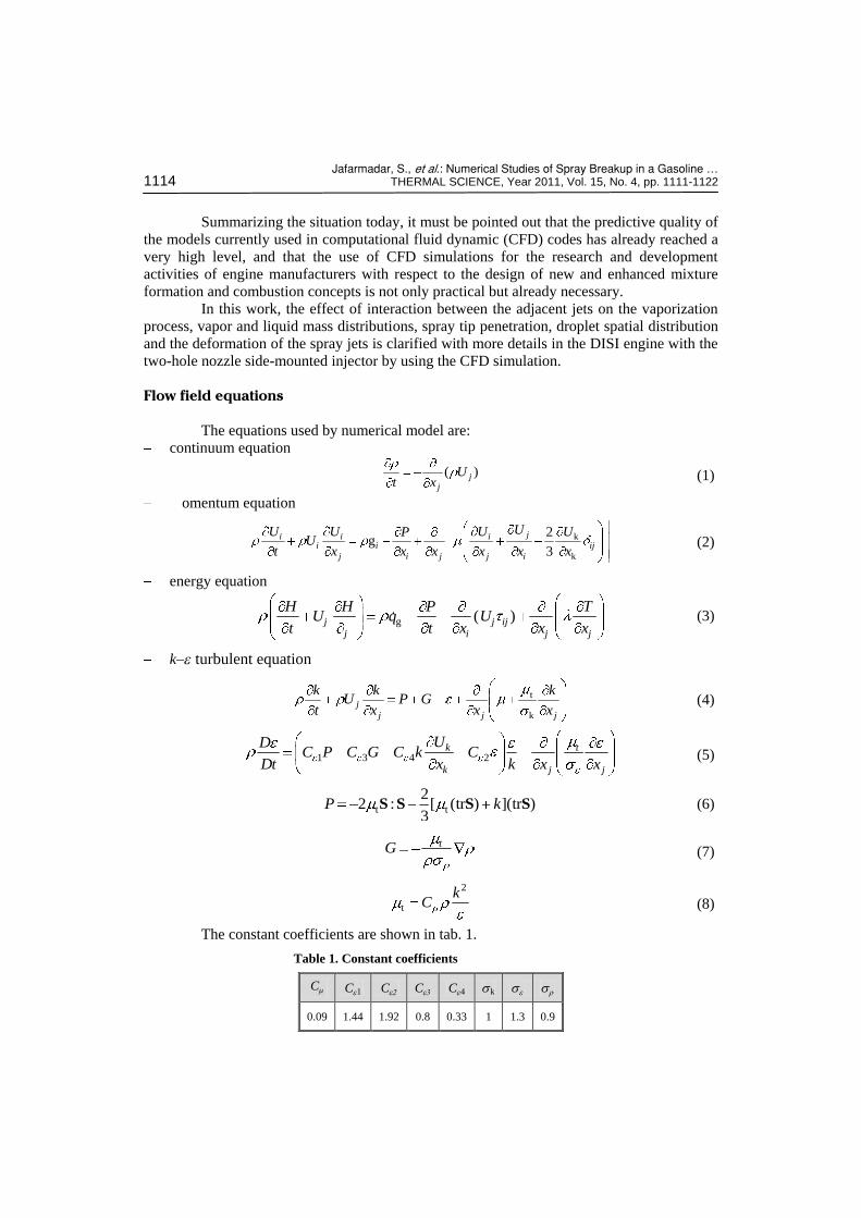
Flow field equations
The equations used by numerical model are:
continuum equation
( )j
j
Ut x
(1)
omentum equation
k
k
2g
3
ji i ii i ij
j i j j i
UU U U UPU
t x x x x x x (2)
energy equation
g ( )j j ij
j i j j
H H P TU q U
t t x x x (3)
k-e turbulent equation
t
k
j
j j j
k k kU P G
t x x x (4)
1 3 4 2k t
k j j
UDC P C G C k C
Dt x k x x (5)
t t
22 : [ (tr ) ](tr )
3P kS S S S (6)
tG (7)
2
t
kC (8)
The constant coefficients are shown in tab. 1.
Table 1. Constant coefficients
Cm Ce1 Ce2 Ce3 Ce4 sk se sr
0.09 1.44 1.92 0.8 0.33 1 1.3 0.9
Jafarmadar, S., et al.: Numerical Studies of Spray Breakup in a Gasoline … THERMAL SCIENCE, Year 2011, Vol. 15, No. 4, pp. 1111-1122 1115
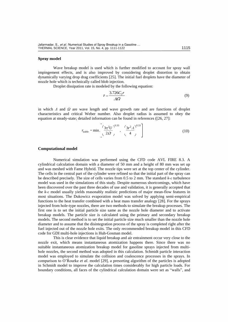
Spray model
Wave breakup model is used which is further modified to account for spray wall
impingement effects, and is also improved by considering droplet distortion to obtain
dynamically varying drop drag coefficients [25]. The initial fuel droplets have the diameter of
nozzle hole which is technically called blob injection.
Droplet dissipation rate is modeled by the following equation:
23.726C r (9)
in which Λ and Ω are wave length and wave growth rate and are functions of droplet
characteristics and critical Weber number. Also droplet radius is assumed to obey the
equation at steady-state; detailed information can be found in references ([26, 27]:
0.33 0.332 2
stable
3 3min. ,
2 4
U rr (10)
Computational model
Numerical simulation was performed using the CFD code AVL FIRE 8.3. A
cylindrical calculation domain with a diameter of 50 mm and a height of 80 mm was set up
and was meshed with Fame Hybrid. The nozzle tips were set at the top center of the cylinder.
The cells in the central part of the cylinder were refined so that the initial part of the spray can
be described precisely. The size of cells varies from 0.5 to 2 mm. The standard k-ε turbulence
model was used in the simulations of this study. Despite numerous shortcomings, which have
been discovered over the past three decades of use and validation, it is generally accepted that
the k-ε model usually yields reasonably realistic predictions of major mean-flow features in
most situations. The Dukowicz evaporation model was solved by applying semi-empirical
functions to the heat transfer combined with a heat mass transfer analogy [28]. For the sprays
injected from hole-type nozzles, there are two methods to simulate the breakup processes. The
first one is to set the initial particle size same as the nozzle hole diameter and to activate
breakup models. The particle size is calculated using the primary and secondary breakup
models. The second method is to set the initial particle size much smaller than the nozzle hole
diameter and to assume that the disintegration process of the spray is completed right after the
fuel injected out of the nozzle hole exits. The only recommended breakup model in this CFD
code for GDI multi-hole injections is Huh-Gosman model.
This is clear evidence that liquid breakup and air entrainment occur very close to the
nozzle exit, which means instantaneous atomization happens there. Since there was no
suitable instantaneous atomization breakup model for gasoline sprays injected from multi-
hole nozzles, the second method was adopted in this calculation. Schmidt particle interaction
model was employed to simulate the collision and coalescence processes in the sprays. In
comparison to O’Rourke et al. model [29], a presorting algorithm of the particles is adopted
in Schmidt model to improve the calculation times considerably for high particle loads. For
boundary conditions, all faces of the cylindrical calculation domain were set as “walls”, and
Jafarmadar, S., et al.: Numerical Studies of Spray Breakup in a Gasoline … 1116 THERMAL SCIENCE, Year 2011, Vol. 15, No. 4, pp. 1111-1122
all velocities in all directions were set to 0 m/s. A constant temperature of 500 K was set for
all the “walls”. For initial conditions, all the cells in the domain were set to have a uniform
initialization with the pressure of 1 MPa and temperature of 500 K. The initial density of the
ambient gas was calculated according to the ideal gas law. The initial turbulence kinetic
energy was 0.001 m2/s
2 and the initial turbulence length scale was 0.001 m. The
computational parameters are listed in tab. 2.
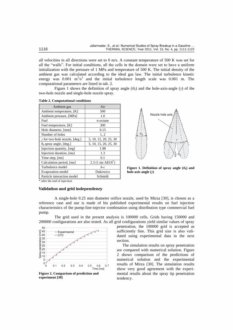
Figure 1 shows the definition of spray angle (θ0) and the hole-axis-angle (γ) of the
two-hole nozzle and single-hole nozzle spray.
Figure 1. Definition of spray angle (θ0) and hole-axis angle (γ)
Validation and grid independency
A single-hole 0.25 mm diameter orifice nozzle, used by Mirza [30], is chosen as a
reference case and use is made of his published experimental results on fuel injection
characteristics of the pump-line-injector combination using distribution type commercial fuel
pump. The grid used in the present analysis is 100000 cells. Grids having 150000 and
200000 configurations are also tested. As all grid configurations yield similar values of spray
penetration, the 100000 grid is accepted as
sufficiently fine. This grid size is also vali-
dated using experimental data in the next
section. The simulation results on spray penetration
are compared with numerical solution. Figure
2 shows comparison of the predictions of
numerical solution and the experimental
results of Mirza [30]. The simulation results
show very good agreement with the experi-
mental results about the spray tip penetration
tendency.
Figure 2. Comparison of prediction and experiment [30]
Table 2. Computational conditions
Ambient gas Air
Ambient temperature, [K] 500
Ambient pressure, [MPa] 1.0
Fuel n-octane
Fuel temperature, [K] 300
Hole diameter, [mm] 0.15
Number of holes 1, 2
γ for two-hole nozzle, [deg.] 5, 10, 15, 20, 25, 30
θ0 spray angle, [deg.] 5, 10, 15, 20, 25, 30
Injection quantity, [mg] 1.88
Injection duration, [ms] 1.3
Time step, [ms] 0.1
Calculation period, [ms] 2.3 (1 ms AEOI*)
Turbulence model k-ε
Evaporation model Dukowicz
Particle interaction model Schmidt
* after the end of injection
Jafarmadar, S., et al.: Numerical Studies of Spray Breakup in a Gasoline … THERMAL SCIENCE, Year 2011, Vol. 15, No. 4, pp. 1111-1122 1117
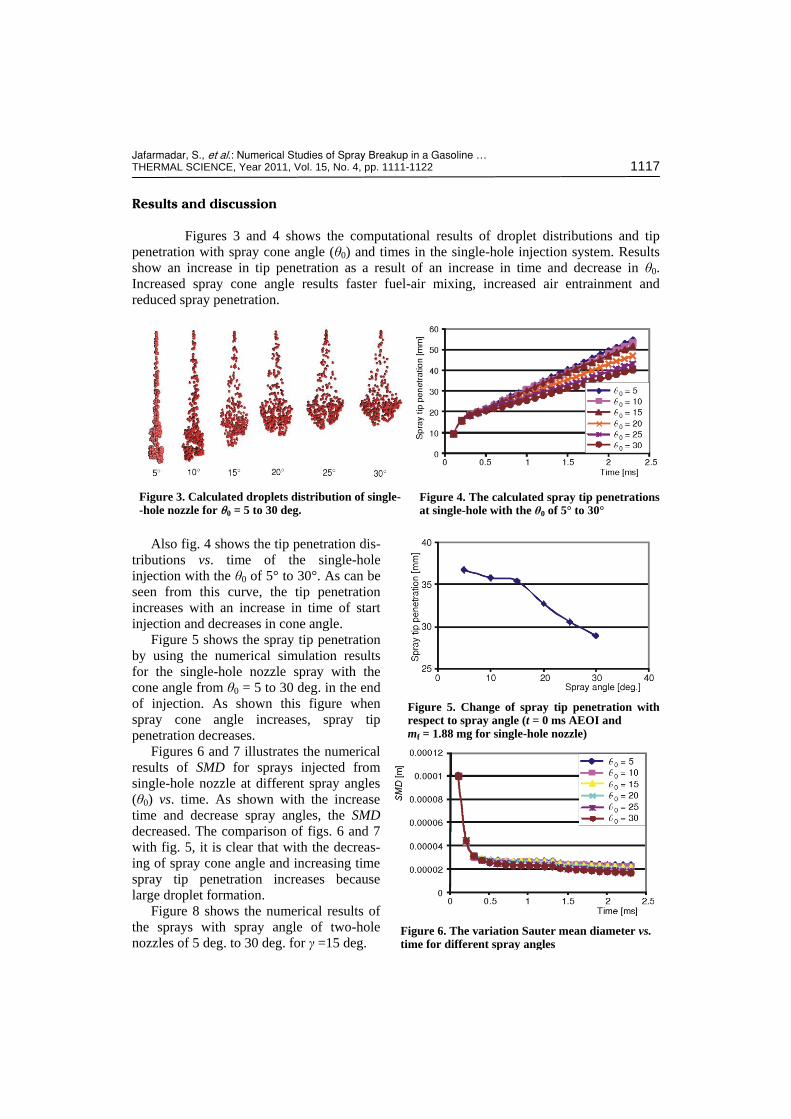
Results and discussion
Figures 3 and 4 shows the computational results of droplet distributions and tip
penetration with spray cone angle (θ0) and times in the single-hole injection system. Results
show an increase in tip penetration as a result of an increase in time and decrease in θ0.
Increased spray cone angle results faster fuel-air mixing, increased air entrainment and
reduced spray penetration.
Figure 3. Calculated droplets distribution of single- -hole nozzle for q0 = 5 to 30 deg.
Figure 4. The calculated spray tip penetrations at single-hole with the θ0 of 5° to 30°
Also fig. 4 shows the tip penetration dis-
tributions vs. time of the single-hole
injection with the θ0 of 5° to 30°. As can be
seen from this curve, the tip penetration
increases with an increase in time of start
injection and decreases in cone angle.
Figure 5 shows the spray tip penetration
by using the numerical simulation results
for the single-hole nozzle spray with the
cone angle from θ0 = 5 to 30 deg. in the end
of injection. As shown this figure when
spray cone angle increases, spray tip
penetration decreases.
Figures 6 and 7 illustrates the numerical
results of SMD for sprays injected from
single-hole nozzle at different spray angles
(θ0) vs. time. As shown with the increase
time and decrease spray angles, the SMD
decreased. The comparison of figs. 6 and 7
with fig. 5, it is clear that with the decreas-
ing of spray cone angle and increasing time
spray tip penetration increases because
large droplet formation.
Figure 8 shows the numerical results of
the sprays with spray angle of two-hole
nozzles of 5 deg. to 30 deg. for γ =15 deg.
Figure 5. Change of spray tip penetration with respect to spray angle (t = 0 ms AEOI and mf = 1.88 mg for single-hole nozzle)
Figure 6. The variation Sauter mean diameter vs. time for different spray angles
Jafarmadar, S., et al.: Numerical Studies of Spray Breakup in a Gasoline … 1118 THERMAL SCIENCE, Year 2011, Vol. 15, No. 4, pp. 1111-1122
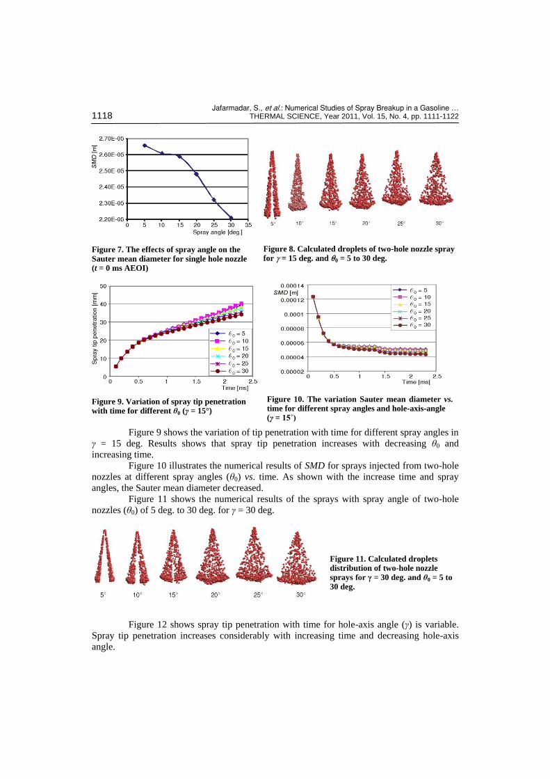
Figure 7. The effects of spray angle on the Sauter mean diameter for single hole nozzle (t = 0 ms AEOI)
Figure 8. Calculated droplets of two-hole nozzle spray for g = 15 deg. and q0 = 5 to 30 deg.
Figure 9. Variation of spray tip penetration with time for different θ0 (γ = 15°)
Figure 10. The variation Sauter mean diameter vs. time for different spray angles and hole-axis-angle (γ = 15˚)
Figure 9 shows the variation of tip penetration with time for different spray angles in
γ = 15 deg. Results shows that spray tip penetration increases with decreasing θ0 and
increasing time.
Figure 10 illustrates the numerical results of SMD for sprays injected from two-hole
nozzles at different spray angles (θ0) vs. time. As shown with the increase time and spray
angles, the Sauter mean diameter decreased.
Figure 11 shows the numerical results of the sprays with spray angle of two-hole
nozzles (θ0) of 5 deg. to 30 deg. for γ = 30 deg.
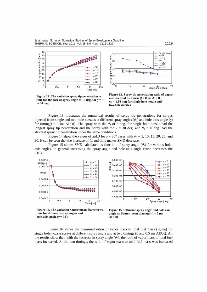
Figure 12 shows spray tip penetration with time for hole-axis angle (γ) is variable.
Spray tip penetration increases considerably with increasing time and decreasing hole-axis
angle.
Figure 11. Calculated droplets distribution of two-hole nozzle sprays for γ = 30 deg. and θ0 = 5 to 30 deg.
Jafarmadar, S., et al.: Numerical Studies of Spray Breakup in a Gasoline … THERMAL SCIENCE, Year 2011, Vol. 15, No. 4, pp. 1111-1122 1119
Figure 12. The variation spray tip penetration vs. time for the case of spray angle of 15 deg. for γ = 5 to 30 deg.
Figure 13. Spray tip penetration ratio of vapor mass to total fuel mass (t = 0 ms AEOI, mf = 1.88 mg) for single-hole nozzle and two-hole nozzles
Figure 13 illustrates the numerical results of spray tip penetrations for sprays
injected from single and two-hole nozzles at different spray angles (θ0) and hole-axis-angle (γ)
for timing(t = 0 ms AEOI). The spray with the θ0 of 5 deg. for single hole nozzle had the
longest spray tip penetration and the spray with the γ = 30 deg. and θ0 =30 deg. had the
shortest spray tip penetration under the same conditions.
Figure 14 show the values of SMD for γ = 30° cases with θ0 = 5, 10, 15, 20, 25, and
30. It can be seen that the increase of θ0 and time makes SMD decrease.
Figure 15 shows SMD calculated as function of spray angle (θ0) for various hole-
axis-angles. In general increasing the spray angle and hole-axis angle cause decreases the
SMD.
Figure 14. The variation Sauter mean diameter vs. time for different spray angles and hole-axis-angle (γ = 30˚)
Figure 15. Influence spray angle and hole axis angle on Sauter mean diameter (t = 0 ms AEOI)
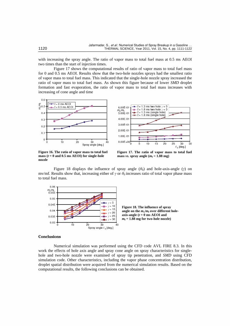
Figure 16 shows the measured ratios of vapor mass to total fuel mass (mv/mf) for
single hole nozzle sprays at different spray angle and at two timings (0 and 0.5 ms AEOI). All
the results show that, with the increase in spray angle (θ0), the ratio of vapor mass to total fuel
mass increased. At the two timings, the ratio of vapor mass to total fuel mass was increased
Jafarmadar, S., et al.: Numerical Studies of Spray Breakup in a Gasoline … 1120 THERMAL SCIENCE, Year 2011, Vol. 15, No. 4, pp. 1111-1122
with increasing the spray angle. The ratio of vapor mass to total fuel mass at 0.5 ms AEOI
two times than the start of injection times.
Figure 17 shows the computational results of ratio of vapor mass to total fuel mass
for 0 and 0.5 ms AEOI. Results show that the two-hole nozzles sprays had the smallest ratio
of vapor mass to total fuel mass. This indicated that the single-hole nozzle spray increased the
ratio of vapor mass to total fuel mass. As shown this figure because of lower SMD droplet
formation and fast evaporation, the ratio of vapor mass to total fuel mass increases with
increasing of cone angle and time
Figure 16. The ratio of vapor mass to total fuel mass (t = 0 and 0.5 ms AEOI) for single-hole nozzle
Figure 17. The ratio of vapor mass to total fuel mass vs. spray angle (mf = 1.88 mg)
Figure 18 displays the influence of spray angle (θ0) and hole-axis-angle (γ) on
mv/mf. Results show that, increasing either of γ or θ0 increases ratio of total vapor phase mass
to total fuel mass.
Figure 18. The influence of spray angle on the mv/mf over different hole-axis-angle (t = 0 ms AEOI and mf = 1.88 mg for two-hole nozzle)
Conclusions
Numerical simulation was performed using the CFD code AVL FIRE 8.3. In this
work the effects of hole axis angle and spray cone angle on spray characteristics for single-
hole and two-hole nozzle were examined of spray tip penetration, and SMD using CFD
simulation code. Other characteristics, including the vapor phase concentration distribution,
droplet spatial distribution were acquired from the numerical simulation results. Based on the
computational results, the following conclusions can be obtained.
Jafarmadar, S., et al.: Numerical Studies of Spray Breakup in a Gasoline … THERMAL SCIENCE, Year 2011, Vol. 15, No. 4, pp. 1111-1122 1121
The single-hole nozzle spray with the θ0 of 5 deg. had the longest spray tip penetration.
The coalescences of droplets made the spray tend to get the longer spray tip penetration.
In the comparison with the two-hole nozzle spray, the single-hole nozzle spray with the θ0
of 5 deg. had the longest spray tip penetration and for the two-hole nozzle spray with the
γ of 30 deg. and θ0 of 30 deg. had the shortest spray tip penetration. When the hole-axis-
angle (γ) increased from 5 to 30 deg, spray tip penetration remained almost constant.
For a single-hole nozzle spray, with the increase in spray angle (θ0), the ratio of vapor
mass to total fuel mass increased.
For a two-hole nozzle spray, the coalescences of the droplets made the ratio of vapor
mass to total fuel mass smaller than that of the single-hole nozzle spray. A smaller hole-
axis-angle (γ) resulted in a smaller ratio of vapor mass to total fuel mass under all
conditions. Also with increasing spray angle (θ0) and hole-axis-angle (γ) the ratio of
vapor mass to total fuel mass increased.
When the spray angle (θ0) and hole–axis-angle (γ) increased from 5 to 30 deg., the SMD,
decreased for single-hole and two-hole nozzles used in this study.
Nomenclature
H – enthalpy, [Jkg–1] k – kinetic energy of turbulence, [m2s–2kg–1] mf – total fuel mass, [mg] mv – total vapor phase mass, [mg] P – pressure, [MPa] q – heat energy of turbulence, [m2s–2kg–1] SMD – Sauter mean diameter, [m] Ta – temperature, [K] t – time, [ms–1] U – velocity, [ms–1]
Greek symbols
ε – dissipation, [m2s–3] γ – hole axis angle, [deg.] θ0 – spray angle of single-hole nozzle, [deg.] l – heat conductivity, [Wm–1K–1] r – density, [kgm–3]
Acronyms
AEOI – after the end of injection DISI – direct injection spark ignition GDI – gasoline direct injection PFI – port-fuel ignition
Reference
[1] Zhao, F. F., Harrington, D. L., Lai, M. C., Automotive Gasoline Direct-Injection Engines, SAE R-315, 2002
[2] Zhao, F. Q., Lai, M. C., Harrington, D. L., A Review of Mixture Preparation and Combustion Strategies for Spark-Ignited Direct Injection Gasoline Engine, SAE paper 970627, 1997
[3] Tagagi, Y., The Role of Mixture Formation in Improving Fuel Economy and Reducing Emissions of Automotive S. I. Engines, FISITA technical paper P0109, 1996
[4] Preussner, C., Kampmann, S., Gasoline Direct Injection, a New Challenge for Future Gasoline Control Systems – Part 2: Injector and Mixture Formation (in German), Motortechnische Zeitschrift, 58 (1997), 10, pp. 592-599
[5] Iwamoto, Y., et al., Development of Gasoline Direct Injection Engine, SAE paper 970541, 1997 [6] Koike, M., et al., Research and Development of a New Direct Injection Gasoline Engine, SAE paper
2000-01-0530, 2000 [7] Han, Z., Yi, J., Trigui, N., Stratified Mixture Formation and Piston Surface Wetting in a DISI Engine,
SAE paper 2002-01-2655, 2002 [8] Stevens, E., Steeper, R., Piston Wetting in an Optical DISI Engine: Fuel Films, Pool Fires, and Soot
Generation, SAE paper 2001-01-1203, 2001 [9] Eichlseder, H., et al., Chancen und Risiken von Ottomotoren mit Direkteinspritzung, Motortechnische
Zeitschrift, 61 (2000), 3, pp. 144-152; Potential and Risks of Gasoline Direct Injection Engines for Passenger Car Drivelines, Motortechnische Zeitschrift Worldwide, 61 (2000), 3, pp. 2-5
Jafarmadar, S., et al.: Numerical Studies of Spray Breakup in a Gasoline … 1122 THERMAL SCIENCE, Year 2011, Vol. 15, No. 4, pp. 1111-1122
[10] Katashiba, H., et al., Improvement of Center Injection Spray Guided DISI Performance, SAE paper 2006-01-1001, 2006
[11] Ortmann, R., et al., Methods and Analysis of Fuel Injection, Mixture Preparation and Charge Stratification in Different Direct Injected SI Engines, SAE paper 2001-01-0970, 2001
[12] Alperstein, M., Schafer, G. H., Villforth III FJ. Texaco’s Stratified Charge Engine-Multifuel, Efficient, Clean, and Practical, SAE paper 740563, 1974
[13] Fujieda, M., Siraisi, T., Oosuga, M., Influence of the Spray Pattern on Combustion Characteristics of the Direct Injection SI Engine (in Japanese), Proceedings, ILASS-Japan 1995, pp. 173-177
[14] Abraham, J., Khan, A., Magi, V., Jet-Jet and Jet-Wall Interactions of Transient Jets from Multi-Hole Injectors, SAE paper 1999-01-0513, 1999
[15] Arai, M., Saito, M., Atomization Characteristics of Jet-to-Jet and Spray-to-Spray Impingement Systems, Atom Sprays, 9 (1999), 4, pp. 399-417
[16] Ashgriz, N., Poo, J. Y., Coalescence and Separation in Binary Collisions of Liquid Drops, J. Fluid Mech., 221 (1990), pp. 183-204
[17] Qian, J., Law, K., Regimes of Coalescence and Separation in Droplet Collision, J. Fluid Mech, 331 (1997), 1, pp. 59-80
[18] Nishida, K., Nomura, S., Matsumoto, Y., Spray and Mixture Properties of Group-Hole Nozzle for D. I. Diesel Engines, Proceedings, ICLASS, 2006
[19] Gao, J., et al., Group-Hole Nozzle Effects on Mixture Formation and in-Cylinder Combustion Processes in Direct-Injection Diesel Engines, SAE paper 2007-01-4050, 2007
[20] Gao, J., Matsumoto, Y., Nishida, K., Effects of Group-Hole Nozzle Specifications on Fuel Atomization and Evaporation of Direct Injection Diesel Sprays, SAE paper 2007-01-1889, 2007
[21] Zhang, Y. Y., Nishida, K., Nomura, S., Spray Characteristics of a Group-Hole Nozzle for Direct-Injection Diesel Engines, Atom Sprays, 16 (2006), 1, pp. 35-49
[22] Park, S. W., Reitz, R. D., Modeling the Effect of Injector Nozzle-Hole Layout on Diesel Engine Fuel Consumption and Emissions, J. Eng. Gas Turb Power-Trans ASME, 130 (2008), 3:032805
[23] Matsumoto, A., et al., Characterization of Diesel Common Rail Spray Behavior for Single- and Double-Hole Nozzles, SAE paper 2008-01-2424, 2008
[24] Jafarmadar, S., et al., Modeling the Effect of Spray/Wall Impingement on Combustion Process and Emission of DI Diesel Engine, Thermal Science, 13 (2009), 3, pp. 23-34
[25] Uludogan, A., Foster, D. E., Reitz R. D., Modeling the Effect of Engine Speed on the Combustion Process and Emissions in a DI Diesel Engine, SAE paper 962056, 1996
[26] Wakisaka, T., Ibaraki, K., An Improvement Droplet Breakup Model for Three Dimensional Diesel Spray Simulation, 3rd KSME, JSME, Thermal Engineering Conference 11-167-162, 1996
[27] Baumgarten, C., Mixture Formation in Internal Combustion Engines, Springer-Verlag Berlin Heidel-berg, 2006
[28] Dukowicz, J. K., Quasi-Steady Droplet Change in the Presence of Convection, Informal Report Los Alamos Scientific Laboratory, N. Mex., USA, 1979, Rep. LA7997-MS
[29] O’Rourke, P. J., Bracco, F. V., in: IMechE –Stratified Charge Automotive Engines Conference, West-minster, London, 1980
[30] Mirza, M. R., Studies of Diesel Sprays Interacting with Cross Flows and Ssolid Boundaries, Ph. D. thesis, UMIST, Manchester, UK, 1991
Paper submitted: October 25, 2010 Paper revised: May 1, 2011 Paper accepted: May 6, 2011