Embed Size (px)
Citation preview

Interleaf EP5000/EP4000 GENERAL, MECHANICAL/ELECTRICAL97.04.01
1156SBG000AA

Interleaf EP5000/EP4000 GENERAL, MECHANICAL/ELECTRICAL97.04.01
i
1149SBG000BA
CONTENTS
GENERAL
1. SPECIFICATIONS G-1. . . . . . . . . . . . . . . . . . . . . . . . . . . . . . . . . . . . . . . . . .
2. PRECAUTIONS FOR INSTALLATION G-4. . . . . . . . . . . . . . . . . . . . . . . . .
3. PRECAUTIONS FOR USE G-5. . . . . . . . . . . . . . . . . . . . . . . . . . . . . . . . . . .
4. HANDLING OF THE CONSUMABLES G-6. . . . . . . . . . . . . . . . . . . . . . . . .
5. SYSTEM OPTIONS G-7. . . . . . . . . . . . . . . . . . . . . . . . . . . . . . . . . . . . . . . . .
1156SBG000BA
MECHANICAL/ELECTRICAL
1. CROSS-SECTIONAL VIEW M-1. . . . . . . . . . . . . . . . . . . . . . . . . . . . . . . . . .
2. COPY PROCESS M-2. . . . . . . . . . . . . . . . . . . . . . . . . . . . . . . . . . . . . . . . . . .
3. DRIVE SYSTEM M-4. . . . . . . . . . . . . . . . . . . . . . . . . . . . . . . . . . . . . . . . . . . .
4. SEQUENTIAL EXPLANATION M-5. . . . . . . . . . . . . . . . . . . . . . . . . . . . . . . .
5. WATCHDOG (CPU OVERRUN MONITOR) FUNCTION M-8. . . . . . . . . .
5-1. Configuration M-8. . . . . . . . . . . . . . . . . . . . . . . . . . . . . . . . . . . . . . . . . . . 5-2. Watchdog Function Post-Processing M-9. . . . . . . . . . . . . . . . . . . . . .
6. MALFUNCTION BYPASS FUNCTION M-10. . . . . . . . . . . . . . . . . . . . . . . . .
7. IMAGE STABILIZATION SYSTEM M-11. . . . . . . . . . . . . . . . . . . . . . . . . . . . .
7-1. AIDC Sensor M-12. . . . . . . . . . . . . . . . . . . . . . . . . . . . . . . . . . . . . . . . . . . 7-2. Image Stabilization Control Processing Timing M-13. . . . . . . . . . . . . . 7-3. Details of Image Stabilization Controls M-14. . . . . . . . . . . . . . . . . . . . .
8. PC DRUM M-16. . . . . . . . . . . . . . . . . . . . . . . . . . . . . . . . . . . . . . . . . . . . . . . . .
9. DRUM CHARGING M-17. . . . . . . . . . . . . . . . . . . . . . . . . . . . . . . . . . . . . . . . . .
9-1. Ozone Filter M-18. . . . . . . . . . . . . . . . . . . . . . . . . . . . . . . . . . . . . . . . . . . . 10. IMAGE ERASE LAMP M-19. . . . . . . . . . . . . . . . . . . . . . . . . . . . . . . . . . . . . . .
11. OPTICAL SECTION M-24. . . . . . . . . . . . . . . . . . . . . . . . . . . . . . . . . . . . . . . . .
11-1. Exposure Lamp M-25. . . . . . . . . . . . . . . . . . . . . . . . . . . . . . . . . . . . . . . 11-2. AE Sensor M-26. . . . . . . . . . . . . . . . . . . . . . . . . . . . . . . . . . . . . . . . . . . .
11-3. Lamp Reflectors M-27. . . . . . . . . . . . . . . . . . . . . . . . . . . . . . . . . . . . . . . 11-4. Aperture Plates M-27. . . . . . . . . . . . . . . . . . . . . . . . . . . . . . . . . . . . . . . 11-5. Scanner and 2nd/3rd Mirror Carriage Movement M-28. . . . . . . . . . .
Interleaf EP5000/EP4000 GENERAL, MECHANICAL/ELECTRICAL97.04.01
ii
CONTENTS
11-6. Lens Movement M-30. . . . . . . . . . . . . . . . . . . . . . . . . . . . . . . . . . . . . . . 11-7. 4th/5th Mirrors Carriage Movement M-31. . . . . . . . . . . . . . . . . . . . . . 11-8. Original Glass Cooling Fan M-32. . . . . . . . . . . . . . . . . . . . . . . . . . . . .
12. ORIGINAL SIZE DETECTING SYSTEM M-33. . . . . . . . . . . . . . . . . . . . . . . .
12-1. Identification of Original Size Detecting Sensors M-33. . . . . . . . . . . 12-2. Original Size Detecting Operation M-33. . . . . . . . . . . . . . . . . . . . . . . . 12-3. Sensor Locations M-34. . . . . . . . . . . . . . . . . . . . . . . . . . . . . . . . . . . . . . 12-4. Size Detection M-35. . . . . . . . . . . . . . . . . . . . . . . . . . . . . . . . . . . . . . . . 12-5. Original Size Detection Timing M-36. . . . . . . . . . . . . . . . . . . . . . . . . . .
13. DEVELOPMENT M-37. . . . . . . . . . . . . . . . . . . . . . . . . . . . . . . . . . . . . . . . . . . .
13-1. Developing Unit Drive Mechanism M-38. . . . . . . . . . . . . . . . . . . . . . . 13-2. Magnet Roller M-39. . . . . . . . . . . . . . . . . . . . . . . . . . . . . . . . . . . . . . . . . 13-3. Developing Bias M-40. . . . . . . . . . . . . . . . . . . . . . . . . . . . . . . . . . . . . . . 13-4. Doctor Blade M-41. . . . . . . . . . . . . . . . . . . . . . . . . . . . . . . . . . . . . . . . . . 13-5. ATDC Sensor M-42. . . . . . . . . . . . . . . . . . . . . . . . . . . . . . . . . . . . . . . . . 13-6. Sub Hopper Toner Replenishing Mechanism M-44. . . . . . . . . . . . . . 13-7. Sub Hopper Toner Empty Detection Control M-45. . . . . . . . . . . . . . . 13-8. Main Hopper Toner Replenishing Mechanism M-46. . . . . . . . . . . . . . 13-9. Swing Out/In the Main Hopper M-47. . . . . . . . . . . . . . . . . . . . . . . . . . .
14. IMAGE TRANSFER AND PAPER SEPARATION M-48. . . . . . . . . . . . . . . .
14-1. Ozone Filter M-49. . . . . . . . . . . . . . . . . . . . . . . . . . . . . . . . . . . . . . . . . . 15. PAPER SEPARATOR FINGERS M-50. . . . . . . . . . . . . . . . . . . . . . . . . . . . . .
16. CLEANING UNIT M-53. . . . . . . . . . . . . . . . . . . . . . . . . . . . . . . . . . . . . . . . . . .
16-1. Spent Toner Collection M-54. . . . . . . . . . . . . . . . . . . . . . . . . . . . . . . . . 16-2. Cleaning Bias (Optional) M-56. . . . . . . . . . . . . . . . . . . . . . . . . . . . . . . .
17. MAIN ERASE LAMP M-57. . . . . . . . . . . . . . . . . . . . . . . . . . . . . . . . . . . . . . . . .
18. PAPER TAKE-UP/FEED SECTION M-58. . . . . . . . . . . . . . . . . . . . . . . . . . . .
18-1. Drawer-in-Position Detection M-59. . . . . . . . . . . . . . . . . . . . . . . . . . . . 18-2. Drawer Paper Lifting/Lowering Mechanism/Control M-60. . . . . . . . . 18-3. Paper Level Detection M-65. . . . . . . . . . . . . . . . . . . . . . . . . . . . . . . . . . 18-4. Paper Empty Detection M-66. . . . . . . . . . . . . . . . . . . . . . . . . . . . . . . . . 18-5. Universal Tray (2nd Drawer) Paper Size Detection M-68. . . . . . . . . 18-6. Paper Take-Up Mechanism M-71. . . . . . . . . . . . . . . . . . . . . . . . . . . . . 18-7. Paper Take-Up Control M-74. . . . . . . . . . . . . . . . . . . . . . . . . . . . . . . . .
19. MULTI BYPASS TABLE M-76. . . . . . . . . . . . . . . . . . . . . . . . . . . . . . . . . . . . . .
19-1. Paper Take-Up Mechanism M-77. . . . . . . . . . . . . . . . . . . . . . . . . . . . . 19-2. Paper Separating Mechanism M-78. . . . . . . . . . . . . . . . . . . . . . . . . . . 19-3. Paper Empty Detection M-79. . . . . . . . . . . . . . . . . . . . . . . . . . . . . . . . .
Interleaf EP5000/EP4000 GENERAL, MECHANICAL/ELECTRICAL97.04.01
iii
CONTENTS20. VERTICAL PAPER TRANSPORT M-80. . . . . . . . . . . . . . . . . . . . . . . . . . . . .
21. SYNCHRONIZING ROLLERS M-81. . . . . . . . . . . . . . . . . . . . . . . . . . . . . . . .
21-1. Synchronizing Roller Drive Mechanism M-82. . . . . . . . . . . . . . . . . . . 21-2. Paper Dust Remover M-82. . . . . . . . . . . . . . . . . . . . . . . . . . . . . . . . . . . 21-3. Synchronizing Roller Control M-83. . . . . . . . . . . . . . . . . . . . . . . . . . . . 21-4. Prevention of Low Image Density on Copy M-84. . . . . . . . . . . . . . . .
22. PAPER TRANSPORT M-86. . . . . . . . . . . . . . . . . . . . . . . . . . . . . . . . . . . . . . .
22-1. Suction Belt Drive Mechanism M-87. . . . . . . . . . . . . . . . . . . . . . . . . . . 23. FUSING UNIT M-88. . . . . . . . . . . . . . . . . . . . . . . . . . . . . . . . . . . . . . . . . . . . . .
23-1. Fusing Temperature Control M-89. . . . . . . . . . . . . . . . . . . . . . . . . . . . . 23-2. Fusing Rollers Pressure Mechanism M-90. . . . . . . . . . . . . . . . . . . . . 23-3. Cleaning Roller M-91. . . . . . . . . . . . . . . . . . . . . . . . . . . . . . . . . . . . . . . . 23-4. Paper Separator Fingers M-92. . . . . . . . . . . . . . . . . . . . . . . . . . . . . . . 23-5. Fusing Section Cooling Fan M-93. . . . . . . . . . . . . . . . . . . . . . . . . . . . .
24. EXIT UNIT M-94. . . . . . . . . . . . . . . . . . . . . . . . . . . . . . . . . . . . . . . . . . . . . . . . .
24-1. Detection of Left Upper Door in Position M-95. . . . . . . . . . . . . . . . . . 25. DEHUMIDIFYING SWITCH M-96. . . . . . . . . . . . . . . . . . . . . . . . . . . . . . . . . .
26. MEMORY BACKUP M-97. . . . . . . . . . . . . . . . . . . . . . . . . . . . . . . . . . . . . . . . .
Interleaf EP5000/EP4000 GENERAL, MECHANICAL/ELECTRICAL97.04.01
1151SBG000D
SAFETY INFORMATION
ALL Areas
CAUTION
Danger of explosion if battery is incorrectly replaced.Replace only with the same or equivalent type
recommended by the manufacturer.Dispose of used batteries accordingto the manufacturer’s instructions.
Denmark
ADVARSEL!
Lithiumbatteri - Eksplosionsfare ved fejlagtig håndtering.Udskiftning må kun ske med batteri
af samme fabrikat og type.Levér det brugte batteri tilbage til leverandøren.
Norway
ADVARSEL
Eksplosjonsfare ved feilaktig skifte av batteri.Benytt samme batteritype eller en tilsvarende
type anbefalt av apparatfabrikanten.Brukte batterier kasseres i henhold til fabrikantens
instruksjoner.
Sweden
VARNING
Explosionsfara vid felaktigt batteribyte.Använd samma batterityp eller en ekvivalent
typ som rekommenderas av apparattillverkaren.Kassera använt batteri enligt fabrikantens
instruktion.
Finland
VAROITUS
Paristo voi räjähtää, jos se on virheellisesti asennettu.Vaihda paristo ainoastaan laitevalmistajan suosittelemaan
tyyppiin. Hävitä Käytetty paristo valmistajan ohjeidenmukaisesti.

Interleaf EP5000/EP4000 GENERAL, MECHANICAL/ELECTRICAL97.04.01
1151SBG000CA
Interleaf EP5000/EP4000 GENERAL, MECHANICAL/ELECTRICAL97.04.01
G-1
1156SBG0100A
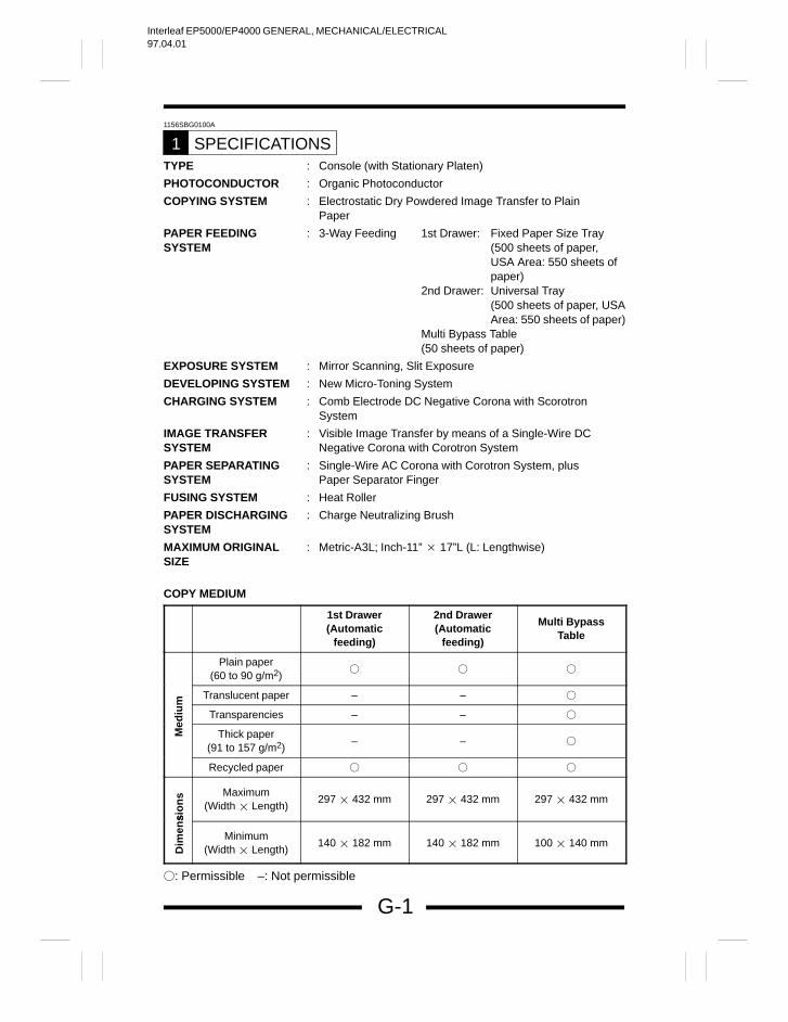
SPECIFICATIONS1TYPE : Console (with Stationary Platen)
PHOTOCONDUCTOR : Organic Photoconductor
COPYING SYSTEM : Electrostatic Dry Powdered Image Transfer to Plain Paper
PAPER FEEDING : 3-Way Feeding 1st Drawer: Fixed Paper Size TraySYSTEM (500 sheets of paper,
USA Area: 550 sheets ofpaper)
2nd Drawer: Universal Tray(500 sheets of paper, USAArea: 550 sheets of paper)
Multi Bypass Table(50 sheets of paper)
EXPOSURE SYSTEM : Mirror Scanning, Slit Exposure
DEVELOPING SYSTEM : New Micro-Toning System
CHARGING SYSTEM : Comb Electrode DC Negative Corona with Scorotron System
IMAGE TRANSFER : Visible Image Transfer by means of a Single-Wire DC SYSTEM Negative Corona with Corotron System
PAPER SEPARATING : Single-Wire AC Corona with Corotron System, plus SYSTEM Paper Separator Finger
FUSING SYSTEM : Heat Roller
PAPER DISCHARGING : Charge Neutralizing BrushSYSTEM
MAXIMUM ORIGINAL : Metric-A3L; Inch-11” 17”L (L: Lengthwise)SIZE
COPY MEDIUM
1st Drawer(Automatic
feeding)
2nd Drawer(Automatic
feeding)
Multi BypassTable
Plain paper(60 to 90 g/m2)
Translucent paper – –
diu
m
Transparencies – –
Me
Thick paper(91 to 157 g/m2)
– –
Recycled paper
sio
ns Maximum
(Width Length)297 432 mm 297 432 mm 297 432 mm
Dim
ens
Minimum(Width Length)
140 182 mm 140 182 mm 100 140 mm
: Permissible –: Not permissible
Interleaf EP5000/EP4000 GENERAL, MECHANICAL/ELECTRICAL97.04.01
G-2
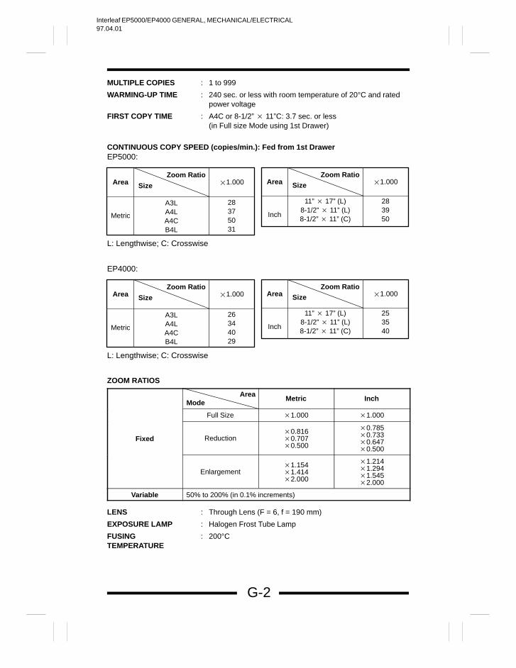
MULTIPLE COPIES : 1 to 999
WARMING-UP TIME : 240 sec. or less with room temperature of 20°C and rated power voltage
FIRST COPY TIME : A4C or 8-1/2” 11”C: 3.7 sec. or less(in Full size Mode using 1st Drawer)
CONTINUOUS COPY SPEED (copies/min.): Fed from 1st DrawerEP5000:
AreaZoom Ratio
Size 1.000
Metric
A3LA4LA4CB4L
28375031
AreaZoom Ratio
Size 1.000
Inch
11” 17” (L)8-1/2” 11” (L)8-1/2” 11” (C)
283950
L: Lengthwise; C: Crosswise
EP4000:
AreaZoom Ratio
Size 1.000
Metric
A3LA4LA4CB4L
26344029
AreaZoom Ratio
Size 1.000
Inch
11” 17” (L)8-1/2” 11” (L)8-1/2” 11” (C)
253540
L: Lengthwise; C: Crosswise
ZOOM RATIOS
Metric Inch
Full Size 1.000 1.000
Fixed Reduction0.8160.7070.500
0.7850.7330.6470.500
Enlargement1.1541.4142.000
1.2141.2941.5452.000
Variable 50% to 200% (in 0.1% increments)
LENS : Through Lens (F = 6, f = 190 mm)
EXPOSURE LAMP : Halogen Frost Tube Lamp
FUSING : 200°CTEMPERATURE
AreaMode
Interleaf EP5000/EP4000 GENERAL, MECHANICAL/ELECTRICAL97.04.01
G-3
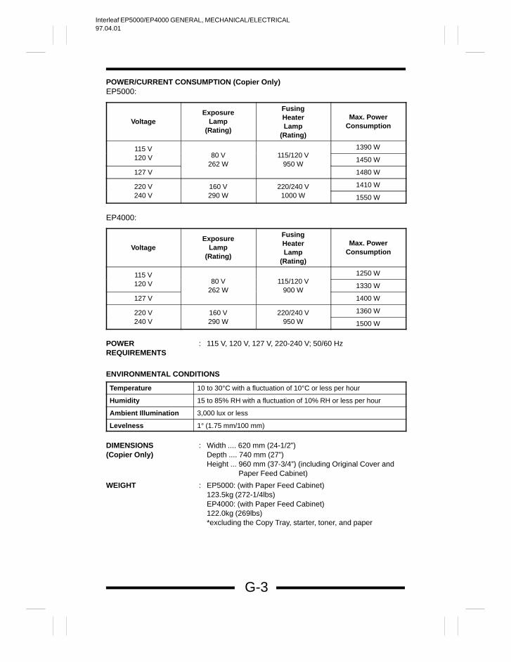
POWER/CURRENT CONSUMPTION (Copier Only)EP5000:
VoltageExposure
Lamp(Rating)
FusingHeaterLamp
(Rating)
Max. PowerConsumption
115 V 1390 W
120 V 80 V 115/120 V1450 W
127 V262 W 950 W
1480 W
220 V 160 V 220/240 V 1410 W
240 V 290 W 1000 W 1550 W
EP4000:
VoltageExposure
Lamp(Rating)
FusingHeaterLamp
(Rating)
Max. PowerConsumption
115 V 1250 W
120 V 80 V 115/120 V1330 W
127 V262 W 900 W
1400 W
220 V 160 V 220/240 V 1360 W
240 V 290 W 950 W 1500 W
POWER : 115 V, 120 V, 127 V, 220-240 V; 50/60 HzREQUIREMENTS
ENVIRONMENTAL CONDITIONS
Temperature 10 to 30°C with a fluctuation of 10°C or less per hour
Humidity 15 to 85% RH with a fluctuation of 10% RH or less per hour
Ambient Illumination 3,000 lux or less
Levelness 1° (1.75 mm/100 mm)
DIMENSIONS : Width .... 620 mm (24-1/2”)(Copier Only) Depth .... 740 mm (27”)
Height ... 960 mm (37-3/4”) (including Original Cover andPaper Feed Cabinet)
WEIGHT : EP5000: (with Paper Feed Cabinet)123.5kg (272-1/4lbs)EP4000: (with Paper Feed Cabinet)122.0kg (269lbs)*excluding the Copy Tray, starter, toner, and paper
Interleaf EP5000/EP4000 GENERAL, MECHANICAL/ELECTRICAL97.04.01
G-4
1149SBG0200A
PRECAUTIONS FOR INSTALLATION2
Installation SiteTo ensure safety and utmost performance of the copier, the copier should NOT beused in a place: Where it will be subjected to extremely high or low temperature or humidity. Which is exposed to direct sunlight. Which is in the direct air stream of an air conditioner, heater or ventilator. Which puts the operator in the direct stream of exhaust from the copier. Which has poor ventilation. Where ammonia gas might be generated. Which does not have a stable, level floor. Where it will be subjected to sudden fluctuations in either temperature or humidity.
If a cold room is quickly heated, condensation forms inside the copier, resulting inblank spots in the copy.
Which is near any kind of heating device. Where it may be splashed with water. Which is dirty or where it will receive undue vibration. Which is near volatile flammables or curtains.
Power SourceUse an outlet with a capacity of 115/120/127V, 1480W or more, or 220-240V, 1550Wor more. If any other electrical equipment is sourced from the same power outlet, make sure
that the capacity of the outlet is not exceeded. Use a power source with little voltage fluctuation. Never connect by means of a multiple socket any other appliances or machines
to the outlet being used for the copier. Make the following checks at frequent intervals:
Is the power plug abnormally hot? Are there any cracks or scrapes in the cord? Has the power plug been inserted fully into the outlet? Does something, including the copier itself, ride on the power cord?
Ensure that the copier does not ride on the power cord or communications cableof other electrical equipment, and that it does not become wedged into or under-neath the mechanism.
GroundingTo prevent receiving electrical shocks in the case of electrical leakage, always groundthe copier. Connect the grounding wire to:
The ground terminal of the outlet. A grounding contact which complies with the local electrical standards.
Never connect the grounding wire to a gas pipe, the grounding wire for a telephone,or a water pipe.
Interleaf EP5000/EP4000 GENERAL, MECHANICAL/ELECTRICAL97.04.01
G-5
1149SBG0300A
PRECAUTIONS FOR USE3
To ensure that the copier is used in an optimum condition, observe the following pre-cautions. Never place a heavy object on the copier or subject the copier to shocks. Insert the power plug all the way into the outlet. Do not attempt to remove any panel or cover which is secured while the copier is
making copies. Do not turn OFF the Power Switch while the copier is making copies. Provide good ventilation when making a large number of copies continuously. Never use flammable sprays near the copier. If the copier becomes inordinately hot or produces abnormal noise, turn it OFF and
unplug it. Do not turn ON the Power Switch at the same time when you plug the power cord
into the outlet. When unplugging the power cord, do not pull on the cord; hold the plug and pull
it out. Do not bring any magnetized object near the copier. Do not place a vase or vessel containing water on the copier. Be sure to turn OFF the Power Switch at the end of the workday or upon power
failure. Use care not to drop paper clips, staples, or other small pieces of metal into the
copier.
Operating EnvironmentThe operating environmental requirements of the copier are as follows.
Temperature: 10°C to 30°C with a fluctuation of 10°C per hour Humidity: 15% to 85% RH with a fluctuation of 10% RH per hour
Power RequirementsThe power source voltage requirements are as follows.
Voltage Fluctuation: AC115/120/127/220-240V 10% (Copying performance assured)6%, –10% (Only AC 127V)–15% (Paper feeding performance assured)
Frequency Fluctuation: 50/60 Hz 0.3%
Interleaf EP5000/EP4000 GENERAL, MECHANICAL/ELECTRICAL97.04.01
G-6
1151SBG0400A
HANDLING OF THE CONSUMABLES4
Before using any consumables, always read the label on its container carefully. Use the right toner. The applicable copier model name is indicated on the Toner
Bottle. Paper can to be easily damaged by dampness. To prevent absorption of moisture,
store paper, which has been removed from its wrapper but not loaded into theDrawer, in a sealed plastic bag in a cool, dark place.
Keep consumables out of the reach of children. Do not touch the PC Drum with bare hands. Store the paper, toner, and other consumables in a place free from direct sunlight
and away from any heating apparatus. The same sized paper is of two kinds, short grain and long grain. Short grain paper
should only be fed through the copier crosswise, long grain paper should only befed lengthwise.
If your hands become soiled with toner, wash them with soap and waterimmediately.
Do not throw away any used consumables (PC Drum, starter, toner, etc.). They areto be collected.
NOTEDo not burn, bury in the ground, or throw into the water any consumables (PC Drum, starter, toner, etc.).
Interleaf EP5000/EP4000 GENERAL, MECHANICAL/ELECTRICAL97.04.01
G-7
1156SBG0500A
SYSTEM OPTIONS5
1, 2
7, 8
65
4
3
9,10
1112
1149M026AA
1138O525AA
1136O061AA 1134O005AA
13
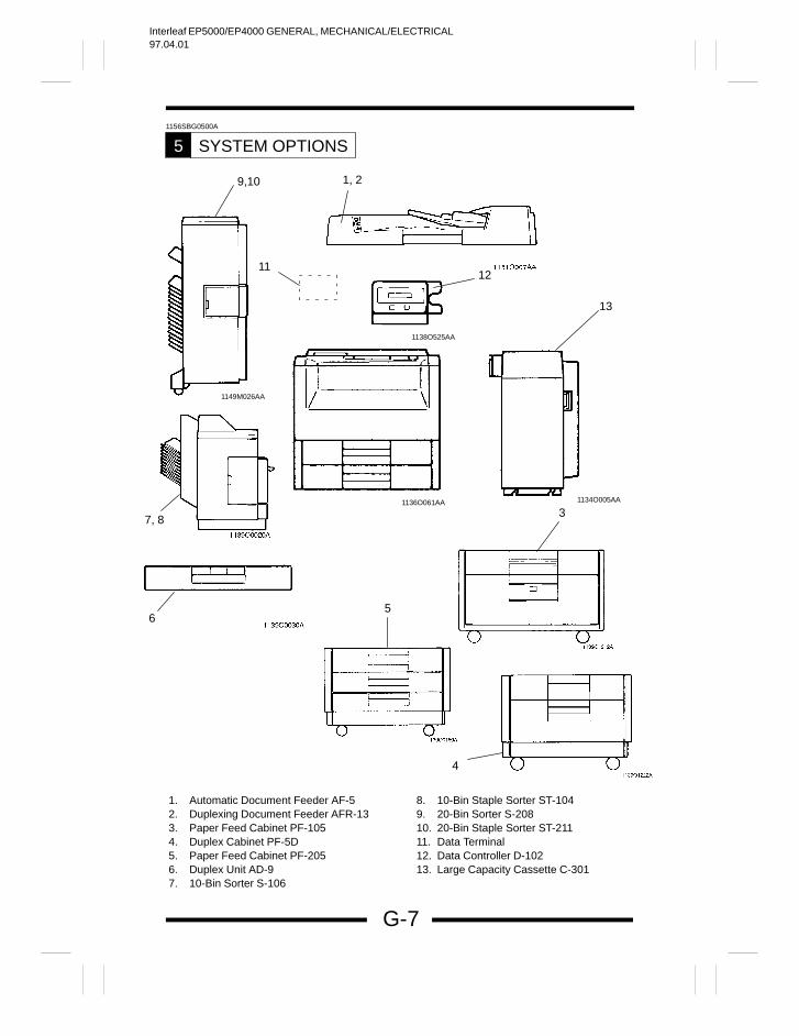
1. Automatic Document Feeder AF-52. Duplexing Document Feeder AFR-133. Paper Feed Cabinet PF-1054. Duplex Cabinet PF-5D5. Paper Feed Cabinet PF-2056. Duplex Unit AD-97. 10-Bin Sorter S-106
8. 10-Bin Staple Sorter ST-1049. 20-Bin Sorter S-20810. 20-Bin Staple Sorter ST-21111. Data Terminal12. Data Controller D-10213. Large Capacity Cassette C-301
Interleaf EP5000/EP4000 GENERAL, MECHANICAL/ELECTRICAL97.04.01
1151SBM000CA
Interleaf EP5000/EP4000 GENERAL, MECHANICAL/ELECTRICAL97.04.01
M-1
1156SBM0100A
CROSS-SECTIONAL VIEW1
21 3 4 5 6 7 8 9 10
23 22 2124
20
18
25
17
16
11 12 13 14
15
1134M001AB
19
2627
28
29
30
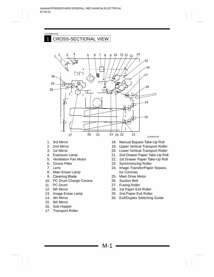
1. 3rd Mirror2. 2nd Mirror3. 1st Mirror4. Exposure Lamp5. Ventilation Fan Motor6. Ozone Filter7. Lens8. Main Erase Lamp9. Cleaning Blade
10. PC Drum Charge Corona11. PC Drum12. 6th Mirror13. Image Erase Lamp14. 4th Mirror15. 5th Mirror16. Sub Hopper17. Transport Roller
18. Manual Bypass Take-Up Roll19. Upper Vertical Transport Roller20. Lower Vertical Transport Roller21. 2nd Drawer Paper Take-Up Roll22. 1st Drawer Paper Take-Up Roll23. Synchronizing Roller24. Image Transfer/Paper Separa-
tor Coronas25. Main Drive Motor26. Suction Belt27. Fusing Roller28. 1st Paper Exit Roller29. 2nd Paper Exit Roller30. Exit/Duplex Switching Guide
Interleaf EP5000/EP4000 GENERAL, MECHANICAL/ELECTRICAL97.04.01
M-2
1156SBM0200A
COPY PROCESS2
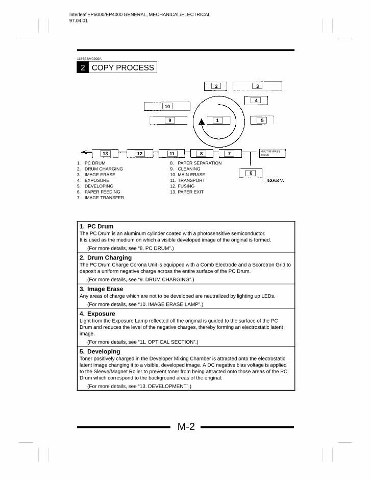
1. PC DRUM2. DRUM CHARGING3. IMAGE ERASE4. EXPOSURE5. DEVELOPING6. PAPER FEEDING7. IMAGE TRANSFER
8. PAPER SEPARATION9. CLEANING10. MAIN ERASE11. TRANSPORT12. FUSING13. PAPER EXIT
1 59
10
2 3
4
6
13 12 11 8 7MULTI BYPASSTABLE
1. PC DrumThe PC Drum is an aluminum cylinder coated with a photosensitive semiconductor. It is used as the medium on which a visible developed image of the original is formed.
(For more details, see “8. PC DRUM”.)
2. Drum ChargingThe PC Drum Charge Corona Unit is equipped with a Comb Electrode and a Scorotron Grid todeposit a uniform negative charge across the entire surface of the PC Drum.
(For more details, see “9. DRUM CHARGING”.)
3. Image EraseAny areas of charge which are not to be developed are neutralized by lighting up LEDs.
(For more details, see “10. IMAGE ERASE LAMP”.)
4. ExposureLight from the Exposure Lamp reflected off the original is guided to the surface of the PCDrum and reduces the level of the negative charges, thereby forming an electrostatic latentimage.
(For more details, see “11. OPTICAL SECTION”.)
5. DevelopingToner positively charged in the Developer Mixing Chamber is attracted onto the electrostaticlatent image changing it to a visible, developed image. A DC negative bias voltage is appliedto the Sleeve/Magnet Roller to prevent toner from being attracted onto those areas of the PCDrum which correspond to the background areas of the original.
(For more details, see “13. DEVELOPMENT”.)
Interleaf EP5000/EP4000 GENERAL, MECHANICAL/ELECTRICAL97.04.01
M-3
6. Paper FeedingPaper is fed either automatically from the 1st or 2nd Drawer, or manually via the Multi BypassTable or Manual Bypass Table. Paper separation is accomplished by the torque limiter fitted tothe Paper Separator Roll.
(For more details, see “18. PAPER TAKE-UP/FEED SECTION”.)
7. Image TransferThe single-wire Image Transfer Corona Unit applies a DC negative corona emission to theunderside of the paper, thereby attracting toner onto the surface of the paper.
(For more details, see “14. IMAGE TRANSFER AND PAPER SEPARATION”.)
8. Paper SeparationThe single-wire Paper Separator Corona Unit applies an AC corona emission to the undersideof the paper to neutralize the paper. In addition, mechanical paper separation is provided bythe two PC Drum Paper Separator Fingers fitted to the Imaging Unit.
(For more details, see “14. IMAGE TRANSFER AND PAPER SEPARATION”.)
9. CleaningResidual toner on the surface of the PC Drum is scraped off by the Cleaning Blade.
(For more details, see “16. CLEANING UNIT”.)
10. Main EraseLight from the Main Erase Lamp neutralizes any surface potential remaining on the surface ofthe PC Drum after cleaning.
(For more details, see “17. MAIN ERASE LAMP”.)
11. TransportThe paper is fed to the Fusing Unit by the Suction Belts.
(For more details, see “22. PAPER TRANSPORT”.)
12. FusingThe developed image is permanently fused to the paper by a combination of heat andpressure applied by the Upper and Lower Fusing Rollers.
(For more details, see “23. FUSING UNIT”.)
13. Paper ExitAfter the fusing process the paper is fed out by the Paper Exit Roller onto the Copy Tray.
(For more details, see “24. EXIT UNIT”.)
Interleaf EP5000/EP4000 GENERAL, MECHANICAL/ELECTRICAL97.04.01
M-4
1156SBM0300A
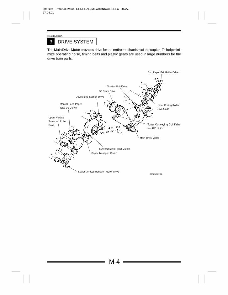
DRIVE SYSTEM3
The Main Drive Motor provides drive for the entire mechanism of the copier. To help mini-mize operating noise, timing belts and plastic gears are used in large numbers for thedrive train parts.
1136M002AA
2nd Paper Exit Roller Drive
Upper Fusing Roller
Drive Gear
Toner Conveying Coil Drive
(on PC Unit)
Main Drive Motor
Synchronizing Roller Clutch
Paper Transport Clutch
Lower Vertical Transport Roller Drive
Upper Vertical
Transport Roller
Drive
Manual Feed Paper
Take-Up Clutch
Developing Section Drive
PC Drum Drive
Suction Unit Drive
Interleaf EP5000/EP4000 GENERAL, MECHANICAL/ELECTRICAL97.04.01
M-5
1156SBM0400A
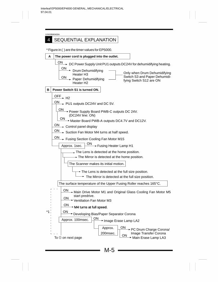
SEQUENTIAL EXPLANATION4
A The power cord is plugged into the outlet.
ON
ON
ON Paper DehumidifyingHeater H2
Drum DehumidifyingHeater H3
DC Power Supply Unit PU1 outputs DC24V for dehumidifying heating.
Only when Drum DehumidifyingSwitch S3 and Paper Dehumidi-fying Switch S12 are ON
B Power Switch S1 is turned ON.
OFF
ONH2
PU1 outputs DC24V and DC 5V.
ON Fusing Section Cooling Fan Motor M15
ON Control panel displayON Suction Fan Motor M4 turns at half speed.
Approx. 1sec. Fusing Heater Lamp H1ON
ON Power Supply Board PWB-C outputs DC 24V.(DC24V line: ON)
ONMaster Board PWB-A outputs DC4.7V and DC12V.
The Lens is detected at the home position.
The Mirror is detected at the home position.
The Scanner makes its initial motion.
The Lens is detected at the full size position.
The Mirror is detected at the full size position.
The surface temperature of the Upper Fusing Roller reaches 165°C.
ON Main Drive Motor M1 and Original Glass Cooling Fan Motor M5start predrive.
ONVentilation Fan Motor M3
ONM4 turns at full speed.
ONDeveloping Bias/Paper Separator Corona
Approx. 100msec. ONImage Erase Lamp LA2
Approx.
200msec.
ON
ON
PC Drum Charge Corona/Image Transfer Corona
M4 turns at full speed.
Main Erase Lamp LA3To on next page
*1
* Figure in ( ) are the timer values for EP5000.
Interleaf EP5000/EP4000 GENERAL, MECHANICAL/ELECTRICAL97.04.01
M-6
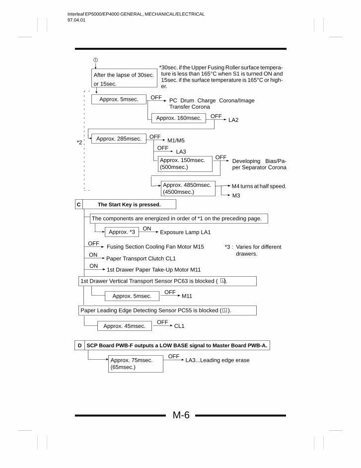
C The Start Key is pressed.
After the lapse of 30sec.
or 15sec.
*30sec. if the Upper Fusing Roller surface tempera-ture is less than 165°C when S1 is turned ON and15sec. if the surface temperature is 165°C or high-er.
Approx. 5msec. OFF PC Drum Charge Corona/ImageTransfer Corona
Approx. 160msec. OFFLA2
Approx. 285msec. OFFM1/M5
OFFLA3
Approx. 150msec.(500msec.)
OFFDeveloping Bias/Pa-per Separator Corona
Approx. 4850msec.(4500msec.)
M4 turns at half speed.
M3
*2
The components are energized in order of *1 on the preceding page.
Approx. *3ON
Exposure Lamp LA1
OFF Fusing Section Cooling Fan Motor M15ON
Paper Transport Clutch CL1ON
1st Drawer Paper Take-Up Motor M11
1st Drawer Vertical Transport Sensor PC63 is blocked ( ).L
Approx. 5msec.OFF
M11
Paper Leading Edge Detecting Sensor PC55 is blocked ( ).L
Approx. 45msec.OFF
CL1
D SCP Board PWB-F outputs a LOW BASE signal to Master Board PWB-A.
Approx. 75msec.(65msec.)
OFFLA3...Leading edge erase
*3 : Varies for differentdrawers.
Interleaf EP5000/EP4000 GENERAL, MECHANICAL/ELECTRICAL97.04.01
M-7
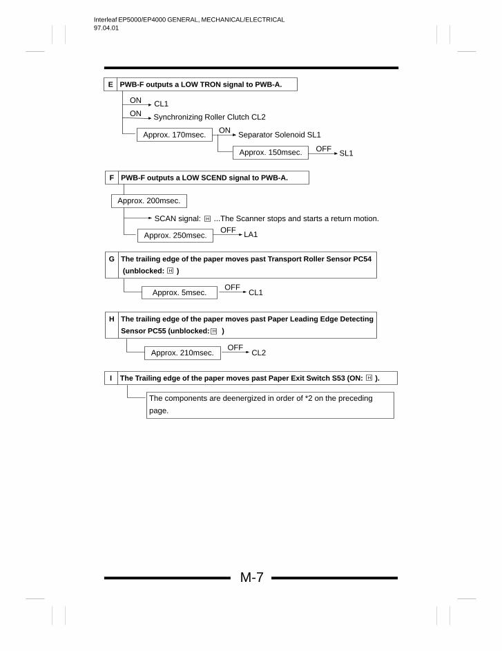
ON
ONCL1
Synchronizing Roller Clutch CL2
E PWB-F outputs a LOW TRON signal to PWB-A.
Approx. 170msec. ON Separator Solenoid SL1
Approx. 150msec. OFF SL1
F PWB-F outputs a LOW SCEND signal to PWB-A.
Approx. 200msec.
SCAN signal: ...The Scanner stops and starts a return motion.H
Approx. 250msec.OFF LA1
G The trailing edge of the paper moves past Transport Roller Sensor PC54
(unblocked: )H
Approx. 5msec.OFF
CL1
H The trailing edge of the paper moves past Paper Leading Edge Detecting
Sensor PC55 (unblocked: )H
Approx. 210msec.OFF
CL2
I The Trailing edge of the paper moves past Paper Exit Switch S53 (ON: ).H
The components are deenergized in order of *2 on the preceding
page.
Interleaf EP5000/EP4000 GENERAL, MECHANICAL/ELECTRICAL97.04.01
M-8
1149SBM0500A
WATCHDOG (CPU OVERRUN MONITOR) FUNCTION5
The watchdog function monitors whether any of the CPUs mounted in the copieroverrun. If this function detects that a CPU overruns, the copier automatically resets theCPU, thereby restarting the logic circuit and mechanism.
Even if a copier CPU operates erratically due to electrical noise, therefore, the copieris able to recover from the faulty condition so that the number of visits made by theTechnical Representative for CPU overrun can be minimized.
1156SBM0501A
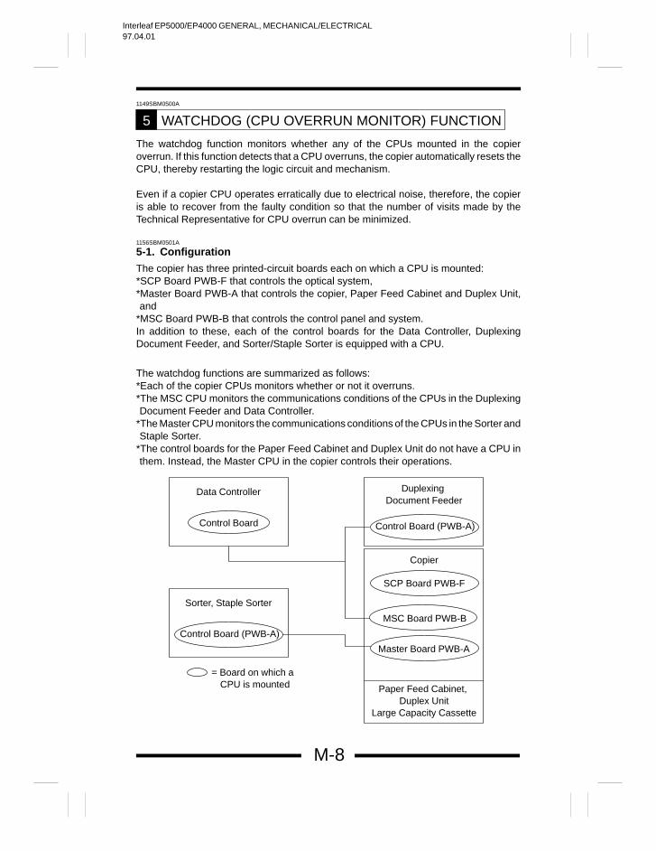
5-1. Configuration
The copier has three printed-circuit boards each on which a CPU is mounted:*SCP Board PWB-F that controls the optical system,*Master Board PWB-A that controls the copier, Paper Feed Cabinet and Duplex Unit,and
*MSC Board PWB-B that controls the control panel and system.In addition to these, each of the control boards for the Data Controller, DuplexingDocument Feeder, and Sorter/Staple Sorter is equipped with a CPU.
The watchdog functions are summarized as follows:*Each of the copier CPUs monitors whether or not it overruns.*The MSC CPU monitors the communications conditions of the CPUs in the DuplexingDocument Feeder and Data Controller.
*The Master CPU monitors the communications conditions of the CPUs in the Sorter andStaple Sorter.
*The control boards for the Paper Feed Cabinet and Duplex Unit do not have a CPU inthem. Instead, the Master CPU in the copier controls their operations.
Data Controller
Control Board
Sorter, Staple Sorter
Control Board (PWB-A)
Duplexing Document Feeder
Copier
SCP Board PWB-F
MSC Board PWB-B
Master Board PWB-A
Paper Feed Cabinet, Duplex Unit
Large Capacity Cassette
= Board on which aCPU is mounted
Control Board (PWB-A)
Interleaf EP5000/EP4000 GENERAL, MECHANICAL/ELECTRICAL97.04.01
M-9
1149SBM0502A
5-2. Watchdog Function Post-Processing
The following processing is performed if a faulty condition is detected in the CPU.When the copier CPU is found faulty:
All CPUs including those of the options are reset and the system is restarted. If theCPU is found faulty during a copy cycle, the system attempts to feed all sheets ofpaper out of the copier before resetting. (If paper is left inside the copier, the copierdetects it as a misfeed as it is restarted.)
When an option CPU is found faulty: The option relays are turned OFF and ON and all options are then restarted. If the
CPU is found faulty during a copy cycle, the copier stops the paper take-upsequence and feeds all sheets of paper out of the copier before resetting.
The Watchdog Counter available from the Tech. Rep. mode allows the TechnicalRepresentative to check if any faulty condition has occurred in the CPU. For details, seeSWITCHES ON PWBs.
Interleaf EP5000/EP4000 GENERAL, MECHANICAL/ELECTRICAL97.04.01
M-10
1156SBM0600A
MALFUNCTION BYPASS FUNCTION6
When a malfunction occurs in the copier, the malfunction bypass function permitsthe copier to continue operating if that malfunction is one of the predefinedcandidates for an isolated malfunction and if it will not affect the current copyingoperation. But, if an isolated malfunction occurs anytime during the actual copycycle, the copier considers it a normal malfunction.
If a copying function involving an isolated malfunction is selected, the message“Selected mode can’t be used.” appears on the Touch Panel and the copier rejectsthat function.
When an isolated malfunction occurs, a tiny wrench “ ” indicator appears in thelower left corner of the Basic Screen. Access the “Machine Status” display bytouching the wrench icon or via the Tech. Rep. mode to ascertain the trouble code.Then refer to the Troubleshooting Manual for details.
Trouble codes for up to five isolated malfunctions are shown on the “MachineStatus” display. When a sixth isolated malfunction occurs, the copier considers ita normal malfunction, prompting a Tech. Rep. call. (The sixth malfunction is shownon the Touch Panel.) But, if all of the paper feed ports (except the manual feed port)show an isolated malfunction, the copier considers them a normal malfunction eventhough the isolated malfunction count may be less than five. The display also tellsthe condition when the image stabilization controls are not properly working.
For the details of the Isolated malfunction codes, see TROUBLESHOOTING for the
copier and the specific SERVICE MANUAL for the options.
Interleaf EP5000/EP4000 GENERAL, MECHANICAL/ELECTRICAL97.04.01
M-11
1149SBM0700A
IMAGE STABILIZATION SYSTEM7
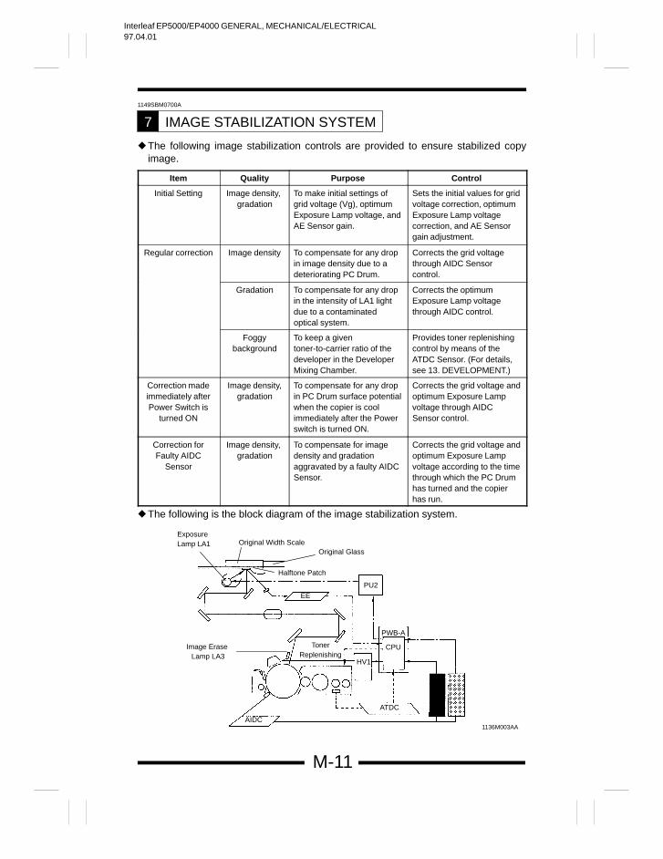
The following image stabilization controls are provided to ensure stabilized copyimage.
Item Quality Purpose Control
Initial Setting Image density, gradation
To make initial settings ofgrid voltage (Vg), optimumExposure Lamp voltage, andAE Sensor gain.
Sets the initial values for gridvoltage correction, optimumExposure Lamp voltagecorrection, and AE Sensorgain adjustment.
Regular correction Image density To compensate for any dropin image density due to adeteriorating PC Drum.
Corrects the grid voltagethrough AIDC Sensorcontrol.
Gradation To compensate for any dropin the intensity of LA1 lightdue to a contaminatedoptical system.
Corrects the optimumExposure Lamp voltagethrough AIDC control.
Foggybackground
To keep a giventoner-to-carrier ratio of thedeveloper in the DeveloperMixing Chamber.
Provides toner replenishingcontrol by means of theATDC Sensor. (For details,see 13. DEVELOPMENT.)
Correction madeimmediately afterPower Switch is
turned ON
Image density,gradation
To compensate for any dropin PC Drum surface potentialwhen the copier is coolimmediately after the Powerswitch is turned ON.
Corrects the grid voltage andoptimum Exposure Lampvoltage through AIDCSensor control.
Correction forFaulty AIDC
Sensor
Image density, gradation
To compensate for imagedensity and gradationaggravated by a faulty AIDCSensor.
Corrects the grid voltage andoptimum Exposure Lampvoltage according to the timethrough which the PC Drumhas turned and the copierhas run.
The following is the block diagram of the image stabilization system.
1136M003AAAIDC
ATDC
CPU
PWB-A
HV1
PU2
EE
TonerReplenishing
Image Erase Lamp LA3
ExposureLamp LA1 Original Width Scale
Original Glass
Halftone Patch
Interleaf EP5000/EP4000 GENERAL, MECHANICAL/ELECTRICAL97.04.01
M-12
1149SBM0701A
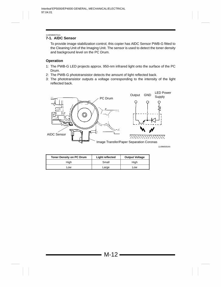
7-1. AlDC Sensor
To provide image stabilization control, this copier has AlDC Sensor PWB-G fitted tothe Cleaning Unit of the Imaging Unit. The sensor is used to detect the toner densityand background level on the PC Drum.
Operation
1: The PWB-G LED projects approx. 950-nm infrared light onto the surface of the PCDrum.
2: The PWB-G phototransistor detects the amount of light reflected back.3: The phototransistor outputs a voltage corresponding to the intensity of the light
reflected back.
Output GNDLED Power SupplyPC Drum
AIDC Sensor
Image Transfer/Paper Separation Coronas1149M005AA
Toner Density on PC Drum Light reflected Output Voltage
High Small High
Low Large Low
Interleaf EP5000/EP4000 GENERAL, MECHANICAL/ELECTRICAL97.04.01
M-13
1156SBM0702A
7-2. Image Stabilization Control Processing Timing
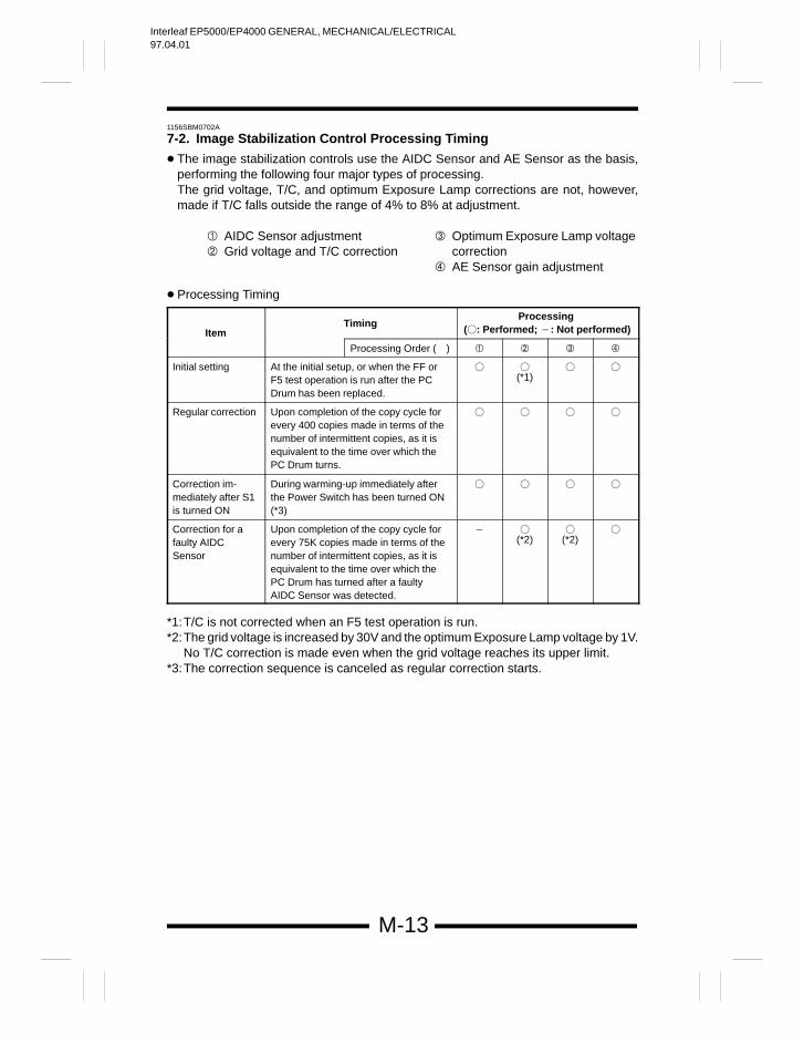
The image stabilization controls use the AIDC Sensor and AE Sensor as the basis,performing the following four major types of processing.The grid voltage, T/C, and optimum Exposure Lamp corrections are not, however,made if T/C falls outside the range of 4% to 8% at adjustment.
AIDC Sensor adjustment Grid voltage and T/C correction
Optimum Exposure Lamp voltagecorrection
AE Sensor gain adjustment
Processing Timing
ItemTiming
Processing (: Performed; : Not performed)
Processing Order ( )
Initial setting At the initial setup, or when the FF orF5 test operation is run after the PCDrum has been replaced.
(*1)
Regular correction Upon completion of the copy cycle forevery 400 copies made in terms of thenumber of intermittent copies, as it isequivalent to the time over which thePC Drum turns.
Correction im-mediately after S1is turned ON
During warming-up immediately afterthe Power Switch has been turned ON(*3)
Correction for afaulty AIDCSensor
Upon completion of the copy cycle forevery 75K copies made in terms of thenumber of intermittent copies, as it isequivalent to the time over which thePC Drum has turned after a faultyAIDC Sensor was detected.
(*2)
(*2)
*1:T/C is not corrected when an F5 test operation is run.*2:The grid voltage is increased by 30V and the optimum Exposure Lamp voltage by 1V.
No T/C correction is made even when the grid voltage reaches its upper limit.*3:The correction sequence is canceled as regular correction starts.
Interleaf EP5000/EP4000 GENERAL, MECHANICAL/ELECTRICAL97.04.01
M-14
1156SBM0703A
7-3. Details of Image Stabilization Controls
AIDC Sensor adjustment Grid voltage and T/C correction
Optimum Exposure Lamp voltagecorrection
AE Sensor gain adjustment
The following is the details of each image stabilization control.
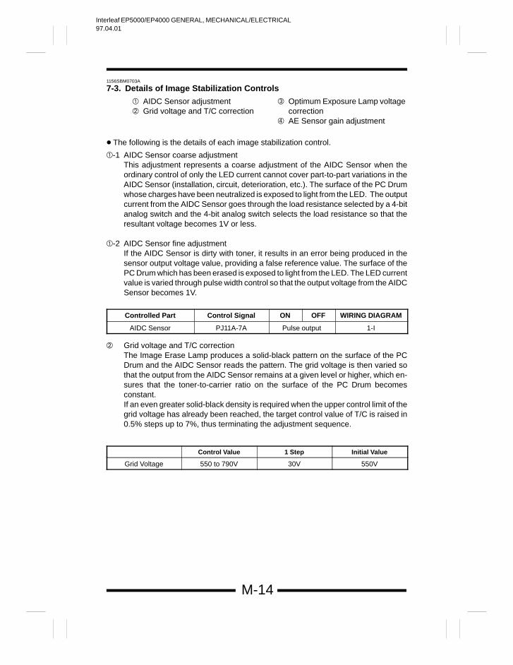
-1 AIDC Sensor coarse adjustmentThis adjustment represents a coarse adjustment of the AIDC Sensor when theordinary control of only the LED current cannot cover part-to-part variations in theAIDC Sensor (installation, circuit, deterioration, etc.). The surface of the PC Drumwhose charges have been neutralized is exposed to light from the LED. The outputcurrent from the AIDC Sensor goes through the load resistance selected by a 4-bitanalog switch and the 4-bit analog switch selects the load resistance so that theresultant voltage becomes 1V or less.
-2 AIDC Sensor fine adjustmentIf the AIDC Sensor is dirty with toner, it results in an error being produced in thesensor output voltage value, providing a false reference value. The surface of thePC Drum which has been erased is exposed to light from the LED. The LED currentvalue is varied through pulse width control so that the output voltage from the AIDCSensor becomes 1V.
Controlled Part Control Signal ON OFF WIRING DIAGRAM
AIDC Sensor PJ11A-7A Pulse output 1-I
Grid voltage and T/C correctionThe Image Erase Lamp produces a solid-black pattern on the surface of the PCDrum and the AIDC Sensor reads the pattern. The grid voltage is then varied sothat the output from the AIDC Sensor remains at a given level or higher, which en-sures that the toner-to-carrier ratio on the surface of the PC Drum becomesconstant.If an even greater solid-black density is required when the upper control limit of thegrid voltage has already been reached, the target control value of T/C is raised in0.5% steps up to 7%, thus terminating the adjustment sequence.
Control Value 1 Step Initial Value
Grid Voltage 550 to 790V 30V 550V
Interleaf EP5000/EP4000 GENERAL, MECHANICAL/ELECTRICAL97.04.01
M-15
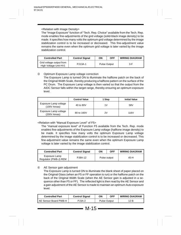
<Relation with Image Density>The “Image Exposure” function of “Tech. Rep. Choice” available from the Tech. Rep.mode enables fine-adjustments of the grid voltage (solid-black image density) to bemade. It specifies how many volts the optimum grid voltage determined by the imagestabilization control is to be increased or decreased. This fine-adjustment valueremains the same even when the optimum grid voltage is later varied by the imagestabilization control.
Controlled Part Control Signal ON OFF WIRING DIAGRAM
Grid voltage output fromHigh Voltage Unit HV1
PJ13A-1 Pulse Output 3-F
Optimum Exposure Lamp voltage correctionThe Exposure Lamp is turned ON to illuminate the halftone patch on the back ofthe Original Width Scale, thereby producing a halftone pattern on the surface of thePC Drum. The Exposure Lamp voltage is then varied so that the output from theAIDC Sensor falls within the target range, thereby ensuring an optimum exposurelevel.
Control Value 1 Step Initial Value
Exposure Lamp voltage(100V Areas)
40 to 80V 1V 58V
Exposure Lamp voltage(200V Areas)
80 to 160V 2V 116V
<Relation with “Manual Exposure Level” of F5>The “manual exposure level” of Function F5 available from the Tech. Rep. modeenables fine-adjustments of the Exposure Lamp voltage (halftone image density) tobe made. It specifies how many volts the optimum Exposure Lamp voltagedetermined by the image stabilization control is to be increased or decreased. Thisfine-adjustment value remains the same even when the optimum Exposure Lampvoltage is later varied by the image stabilization control.
Controlled Part Control Signal ON OFF WIRING DIAGRAM
Exposure Lamp Regulator (PWB-J) REM
PJ8A-12 Pulse output 45-H
AE Sensor gain adjustmentThe Exposure Lamp is turned ON to illuminate the blank sheet of paper placed onthe Original Glass (when an F5 or FF operation is run) or the halftone patch on theback of the Original Width Scale (when the AE Sensor gain is adjusted in a se-quence other than F5 or FF). The reflected light is then read by the AE Sensor anda gain adjustment of the AE Sensor is made to maintain an optimum Auto exposurelevel.
Controlled Part Control Signal ON OFF WIRING DIAGRAM
AE Sensor Board PWB-H PJ3A-2 Pulse Output 12-B
Interleaf EP5000/EP4000 GENERAL, MECHANICAL/ELECTRICAL97.04.01
M-16
1149SBM0800A
PC DRUM8
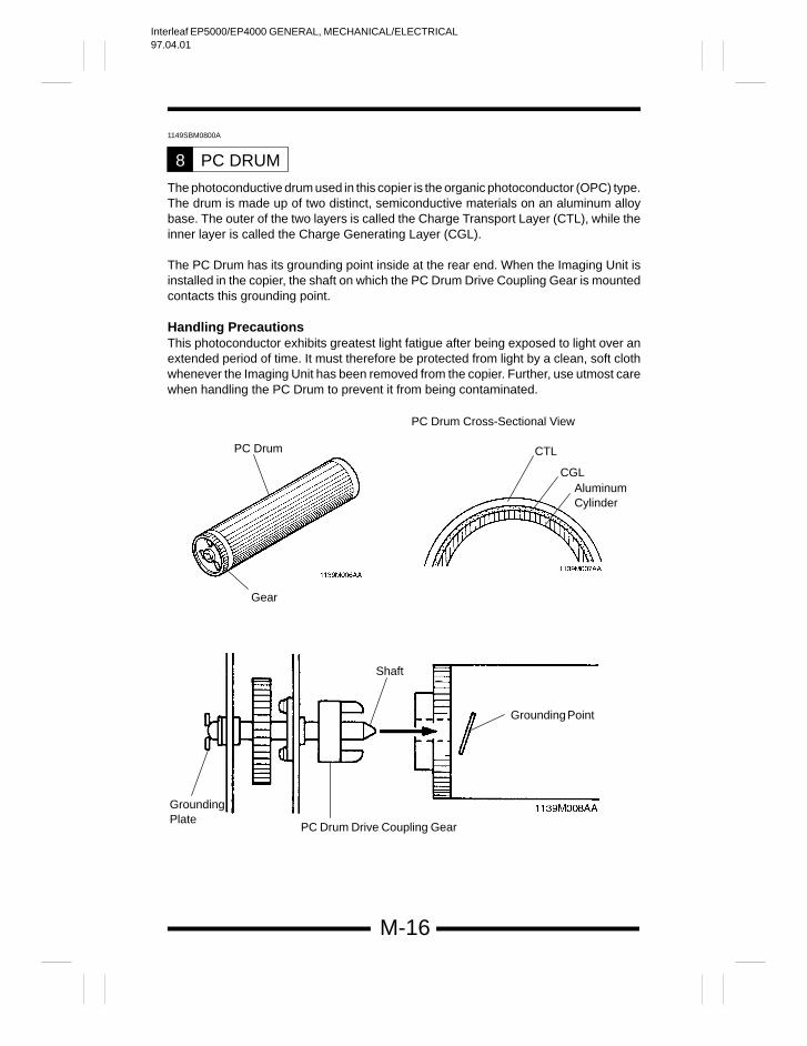
The photoconductive drum used in this copier is the organic photoconductor (OPC) type.The drum is made up of two distinct, semiconductive materials on an aluminum alloybase. The outer of the two layers is called the Charge Transport Layer (CTL), while theinner layer is called the Charge Generating Layer (CGL).
The PC Drum has its grounding point inside at the rear end. When the Imaging Unit isinstalled in the copier, the shaft on which the PC Drum Drive Coupling Gear is mountedcontacts this grounding point.
Handling PrecautionsThis photoconductor exhibits greatest light fatigue after being exposed to light over anextended period of time. It must therefore be protected from light by a clean, soft clothwhenever the Imaging Unit has been removed from the copier. Further, use utmost carewhen handling the PC Drum to prevent it from being contaminated.
PC Drum
Gear
PC Drum Cross-Sectional View
CTL
CGLAluminumCylinder
Shaft
GroundingPlate
PC Drum Drive Coupling Gear
Grounding Point
Interleaf EP5000/EP4000 GENERAL, MECHANICAL/ELECTRICAL97.04.01
M-17
1156SBM0900A
DRUM CHARGING9
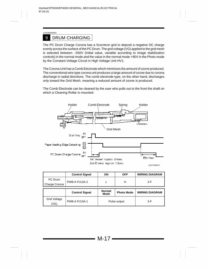
The PC Drum Charge Corona has a Scorotron grid to deposit a negative DC chargeevenly across the surface of the PC Drum. The grid voltage (VG) applied to the grid meshis selected between –550V (initial value, variable according to image stabilizationcontrols) in the normal mode and the value in the normal mode +90V in the Photo modeby the Constant-Voltage Circuit in High Voltage Unit HV1.
The Corona Unit has a Comb Electrode which minimizes the amount of ozone produced.The conventional wire type corona unit produces a large amount of ozone due to coronadischarge in radial directions. The comb electrode type, on the other hand, dischargesonly toward the Grid Mesh, meaning a reduced amount of ozone is produced.
The Comb Electrode can be cleaned by the user who pulls out to the front the shaft onwhich a Cleaning Rollar is mounted.
Holder Comb Electrode Spring Holder
Grid Mesh
1151T03MCC
Control Signal ON OFF WIRING DIAGRAM
PC Drum
Charge CoronaPWB-A PJ13A-2 L H 3-F
Control Signal NormalMode Photo Mode WIRING DIAGRAM
Grid Voltage
(VG)PWB-A PJ13A-1 Pulse output 3-F
Interleaf EP5000/EP4000 GENERAL, MECHANICAL/ELECTRICAL97.04.01
M-18
1156SBM0901A
9-1. Ozone Filter
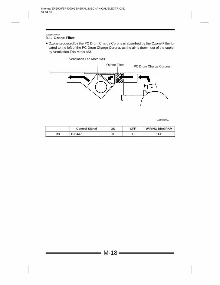
Ozone produced by the PC Drum Charge Corona is absorbed by the Ozone Filter lo-cated to the left of the PC Drum Charge Corona, as the air is drawn out of the copierby Ventilation Fan Motor M3.
1134M004AA
Ventilation Fan Motor M3
Ozone Filter PC Drum Charge Corona
Control Signal ON OFF WIRING DIAGRAM
M3 PJ34A-1 H L 11-F
Interleaf EP5000/EP4000 GENERAL, MECHANICAL/ELECTRICAL97.04.01
M-19
1156SBM1000A
IMAGE ERASE LAMP10
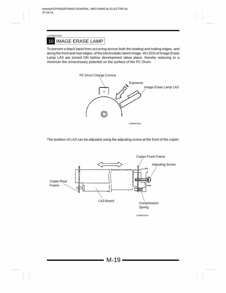
To prevent a black band from occurring across both the leading and trailing edges, andalong the front and rear edges, of the electrostatic latent image, 40 LEDs of Image EraseLamp LA3 are turned ON before development takes place, thereby reducing to aminimum the unnecessary potential on the surface of the PC Drum.
PC Drum Charge Corona
Image Erase Lamp LA3Exposure
1156M010AA
The position of LA3 can be adjusted using the adjusting screw at the front of the copier.
Copier Front Frame
Adjusting Screw
LA3 BoardCompressionSpring
Copier RearFrame
1156M011AA
Interleaf EP5000/EP4000 GENERAL, MECHANICAL/ELECTRICAL97.04.01
M-20
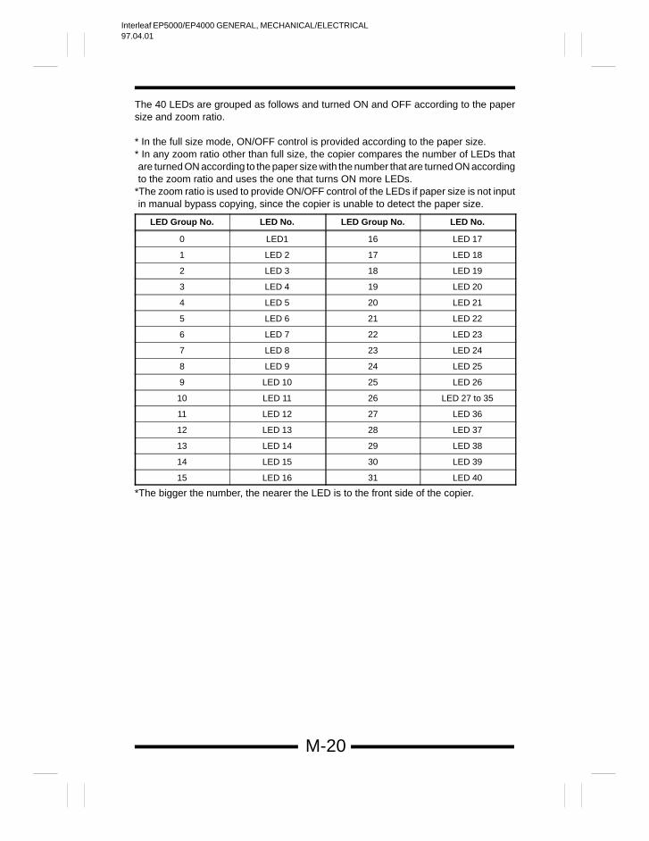
The 40 LEDs are grouped as follows and turned ON and OFF according to the papersize and zoom ratio.
* In the full size mode, ON/OFF control is provided according to the paper size.* In any zoom ratio other than full size, the copier compares the number of LEDs thatare turned ON according to the paper size with the number that are turned ON accordingto the zoom ratio and uses the one that turns ON more LEDs.
*The zoom ratio is used to provide ON/OFF control of the LEDs if paper size is not inputin manual bypass copying, since the copier is unable to detect the paper size.
LED Group No. LED No. LED Group No. LED No.
0 LED1 16 LED 17
1 LED 2 17 LED 18
2 LED 3 18 LED 19
3 LED 4 19 LED 20
4 LED 5 20 LED 21
5 LED 6 21 LED 22
6 LED 7 22 LED 23
7 LED 8 23 LED 24
8 LED 9 24 LED 25
9 LED 10 25 LED 26
10 LED 11 26 LED 27 to 35
11 LED 12 27 LED 36
12 LED 13 28 LED 37
13 LED 14 29 LED 38
14 LED 15 30 LED 39
15 LED 16 31 LED 40
*The bigger the number, the nearer the LED is to the front side of the copier.
Interleaf EP5000/EP4000 GENERAL, MECHANICAL/ELECTRICAL97.04.01
M-21
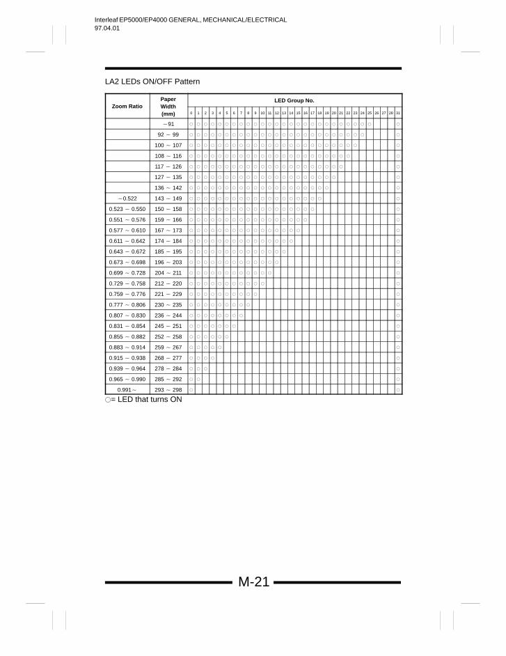
LA2 LEDs ON/OFF Pattern
Paper LED Group No.Zoom Ratio Width
(mm) 0 1 2 3 4 5 6 7 8 9 10 11 12 13 14 15 16 17 18 19 20 21 22 23 24 25 26 27 28 31
91
92 99
100 107
108 116
117 126
127 135
136 142
0.522 143 149
0.523 0.550 150 158
0.551 0.576 159 166
0.577 0.610 167 173
0.611 0.642 174 184
0.643 0.672 185 195
0.673 0.698 196 203
0.699 0.728 204 211
0.729 0.758 212 220
0.759 0.776 221 229
0.777 0.806 230 235
0.807 0.830 236 244
0.831 0.854 245 251
0.855 0.882 252 258
0.883 0.914 259 267
0.915 0.938 268 277
0.939 0.964 278 284
0.965 0.990 285 292
0.991 293 298
= LED that turns ON
Interleaf EP5000/EP4000 GENERAL, MECHANICAL/ELECTRICAL97.04.01
M-22
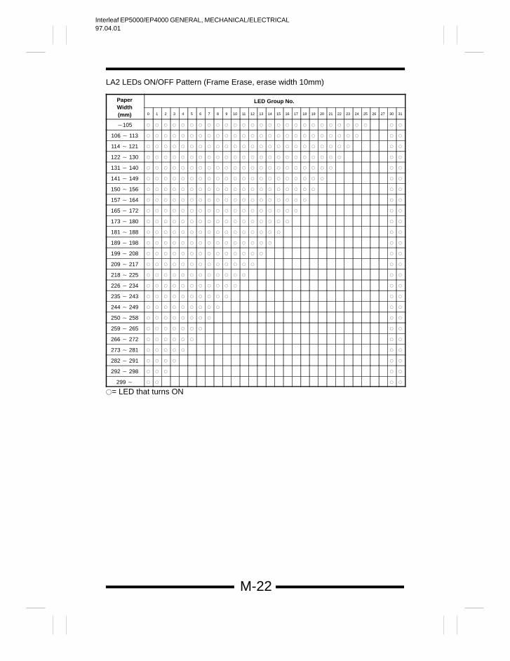
LA2 LEDs ON/OFF Pattern (Frame Erase, erase width 10mm)
Paper LED Group No.Width(mm) 0 1 2 3 4 5 6 7 8 9 10 11 12 13 14 15 16 17 18 19 20 21 22 23 24 25 26 27 30 31
105
106 113
114 121
122 130
131 140
141 149
150 156
157 164
165 172
173 180
181 188
189 198
199 208
209 217
218 225
226 234
235 243
244 249
250 258
259 265
266 272
273 281
282 291
292 298
299
= LED that turns ON
Interleaf EP5000/EP4000 GENERAL, MECHANICAL/ELECTRICAL97.04.01
M-23
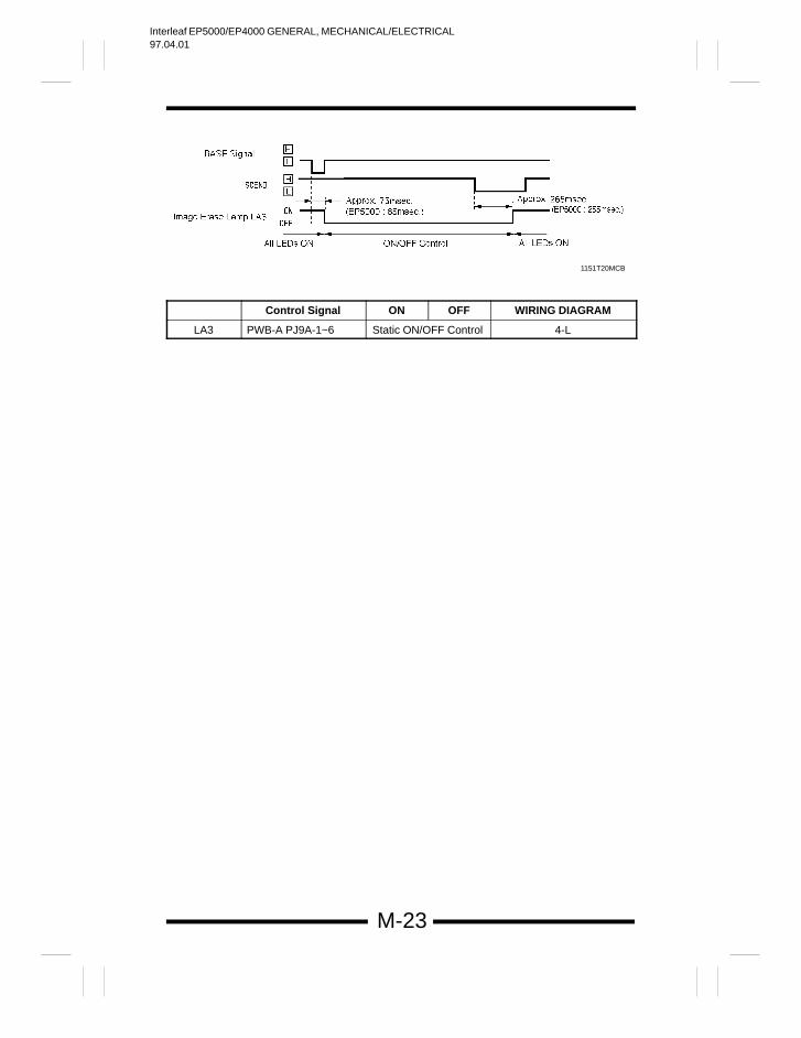
1151T20MCB
Control Signal ON OFF WIRING DIAGRAM
LA3 PWB-A PJ9A-1~6 Static ON/OFF Control 4-L
Interleaf EP5000/EP4000 GENERAL, MECHANICAL/ELECTRICAL97.04.01
M-24
1156SBM1100A
OPTICAL SECTION11
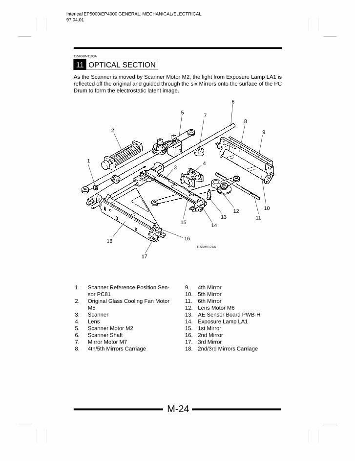
As the Scanner is moved by Scanner Motor M2, the light from Exposure Lamp LA1 isreflected off the original and guided through the six Mirrors onto the surface of the PCDrum to form the electrostatic latent image.
18
1
2
5
7
6
8
9
10
1112
13
1415
16
17
7
34
7
1156M012AA
1. Scanner Reference Position Sen-sor PC81
2. Original Glass Cooling Fan MotorM5
3. Scanner4. Lens5. Scanner Motor M26. Scanner Shaft7. Mirror Motor M78. 4th/5th Mirrors Carriage
9. 4th Mirror10. 5th Mirror11. 6th Mirror12. Lens Motor M613. AE Sensor Board PWB-H14. Exposure Lamp LA115. 1st Mirror16. 2nd Mirror17. 3rd Mirror18. 2nd/3rd Mirrors Carriage
Interleaf EP5000/EP4000 GENERAL, MECHANICAL/ELECTRICAL97.04.01
M-25
1156SBM1101A
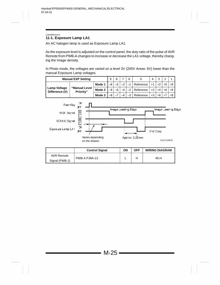
11-1. Exposure Lamp LA1
An AC halogen lamp is used as Exposure Lamp LA1.
As the exposure level is adjusted on the control panel, the duty ratio of the pulse of AVRRemote from PWB-A changes to increase or decrease the LA1 voltage, thereby chang-ing the image density.
In Photo mode, the voltages are varied on a level 3V (200V Areas: 6V) lower than themanual Exposure Lamp voltages.
Manual EXP Setting 9 8 7 6 5 4 3 2 1
Mode 1 –8 –5 –2 –1 Reference +1 +2 +5 +8Lamp Voltage “Manual Level
Mode 2 –8 –6 –4 –2 Reference +2 +4 +6 +8Difference (V) Priority”
Mode 3 –8 –7 –6 –3 Reference +3 +6 +7 +8
1151T21MCBVaries dependingon the drawer.
Control Signal ON OFF WIRING DIAGRAM
AVR Remote
Signal (PWB-J)PWB-A PJ8A-13 L H 45-H
Interleaf EP5000/EP4000 GENERAL, MECHANICAL/ELECTRICAL97.04.01
M-26
1156SBM1102A
11-2. AE Sensor
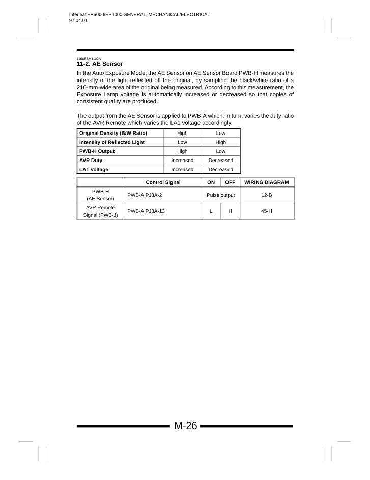
In the Auto Exposure Mode, the AE Sensor on AE Sensor Board PWB-H measures theintensity of the light reflected off the original, by sampling the black/white ratio of a210-mm-wide area of the original being measured. According to this measurement, theExposure Lamp voltage is automatically increased or decreased so that copies ofconsistent quality are produced.
The output from the AE Sensor is applied to PWB-A which, in turn, varies the duty ratioof the AVR Remote which varies the LA1 voltage accordingly.
Original Density (B/W Ratio) High Low
Intensity of Reflected Light Low High
PWB-H Output High Low
AVR Duty Increased Decreased
LA1 Voltage Increased Decreased
Control Signal ON OFF WIRING DIAGRAM
PWB-H(AE Sensor)
PWB-A PJ3A-2 Pulse output 12-B
AVR RemoteSignal (PWB-J)
PWB-A PJ8A-13 L H 45-H
Interleaf EP5000/EP4000 GENERAL, MECHANICAL/ELECTRICAL97.04.01
M-27
1156SBM1103A
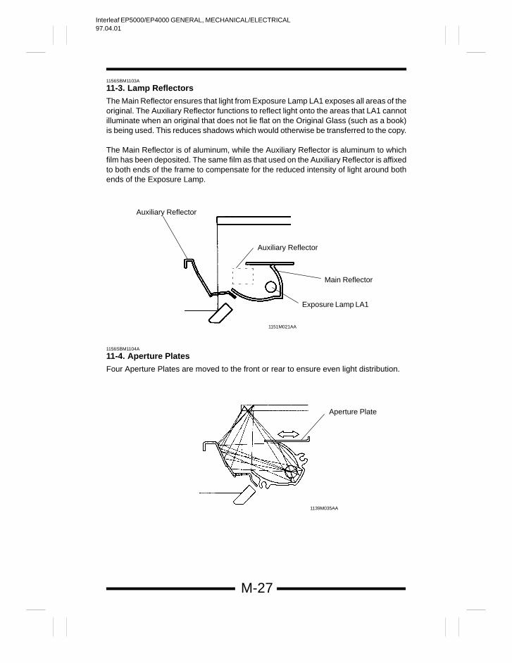
11-3. Lamp Reflectors
The Main Reflector ensures that light from Exposure Lamp LA1 exposes all areas of theoriginal. The Auxiliary Reflector functions to reflect light onto the areas that LA1 cannotilluminate when an original that does not lie flat on the Original Glass (such as a book)is being used. This reduces shadows which would otherwise be transferred to the copy.
The Main Reflector is of aluminum, while the Auxiliary Reflector is aluminum to whichfilm has been deposited. The same film as that used on the Auxiliary Reflector is affixedto both ends of the frame to compensate for the reduced intensity of light around bothends of the Exposure Lamp.
Auxiliary Reflector
Main Reflector
Exposure Lamp LA1
Auxiliary Reflector
1151M021AA
1156SBM1104A
11-4. Aperture Plates
Four Aperture Plates are moved to the front or rear to ensure even light distribution.
Aperture Plate
1139M035AA
Interleaf EP5000/EP4000 GENERAL, MECHANICAL/ELECTRICAL97.04.01
M-28
1156SBM1105A
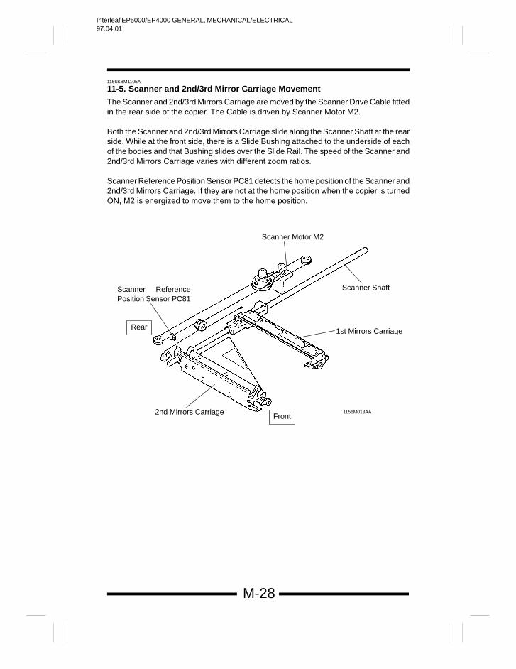
11-5. Scanner and 2nd/3rd Mirror Carriage Movement
The Scanner and 2nd/3rd Mirrors Carriage are moved by the Scanner Drive Cable fittedin the rear side of the copier. The Cable is driven by Scanner Motor M2.
Both the Scanner and 2nd/3rd Mirrors Carriage slide along the Scanner Shaft at the rearside. While at the front side, there is a Slide Bushing attached to the underside of eachof the bodies and that Bushing slides over the Slide Rail. The speed of the Scanner and2nd/3rd Mirrors Carriage varies with different zoom ratios.
Scanner Reference Position Sensor PC81 detects the home position of the Scanner and2nd/3rd Mirrors Carriage. If they are not at the home position when the copier is turnedON, M2 is energized to move them to the home position.
2nd Mirrors Carriage
Scanner Shaft
Scanner Motor M2
Scanner ReferencePosition Sensor PC81
1156M013AA
1st Mirrors CarriageRear
Front
Interleaf EP5000/EP4000 GENERAL, MECHANICAL/ELECTRICAL97.04.01
M-29
The Scanner starts the scan motion as a Scan signal is output from PWB-A. At the startof a scan motion and other heavy load conditions, Scanner Motor M2 requires a largeamount of current. The Current 1 or 2 signal from PWB-F is selected accordingly to varythe amount of current supplied to M2.
*The Current signal selection timing is controlled by software.
L M1 M2
Current 1 H L H
Current 2 H H L
Current M2>M1>L
Operation
When the scanspeed reaches a given level and dur-ing scan deceleration
At scan start and dur-ing return decelera-tion. (*)
At return start andduring return motion.(*)
* M2 is used at scan start of a small zoom ratio.
On receiving the Scan signal, Motor Drive Board PWB-F applies motor drive pulses,which are out-of-phase with each other, to M4. The motor speed is varied by changingthe width of the pulses applied to M2.
Control Signal Energized Deenergized WIRING DIAGRAM
M2Scan Signal
PWB-F L H
M2Current
SwitchingSignal 1
PWB-F L H22-B
M2Current
SwitchingSignal 2
PWB-F L H
Control Signal Blocked Unblocked WIRING DIAGRAM
PC81 PWB-F L H 18-E
Interleaf EP5000/EP4000 GENERAL, MECHANICAL/ELECTRICAL97.04.01
M-30
1156SBM1106A
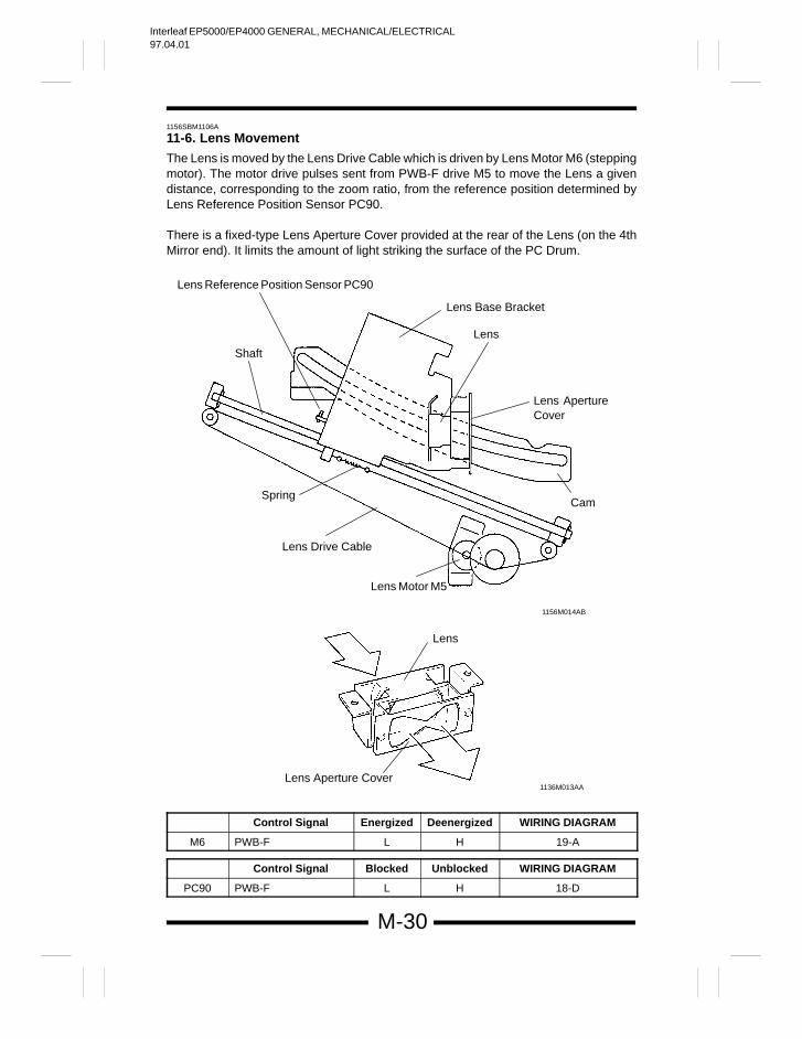
11-6. Lens Movement
The Lens is moved by the Lens Drive Cable which is driven by Lens Motor M6 (steppingmotor). The motor drive pulses sent from PWB-F drive M5 to move the Lens a givendistance, corresponding to the zoom ratio, from the reference position determined byLens Reference Position Sensor PC90.
There is a fixed-type Lens Aperture Cover provided at the rear of the Lens (on the 4thMirror end). It limits the amount of light striking the surface of the PC Drum.
Shaft
Lens Reference Position Sensor PC90
Lens Base Bracket
Lens ApertureCover
Spring
Lens Drive Cable
Lens Motor M5
Lens
Lens Aperture Cover
Cam
1156M014AB
1136M013AA
Lens
Control Signal Energized Deenergized WIRING DIAGRAM
M6 PWB-F L H 19-A
Control Signal Blocked Unblocked WIRING DIAGRAM
PC90 PWB-F L H 18-D
Interleaf EP5000/EP4000 GENERAL, MECHANICAL/ELECTRICAL97.04.01
M-31
1156SBM1107A
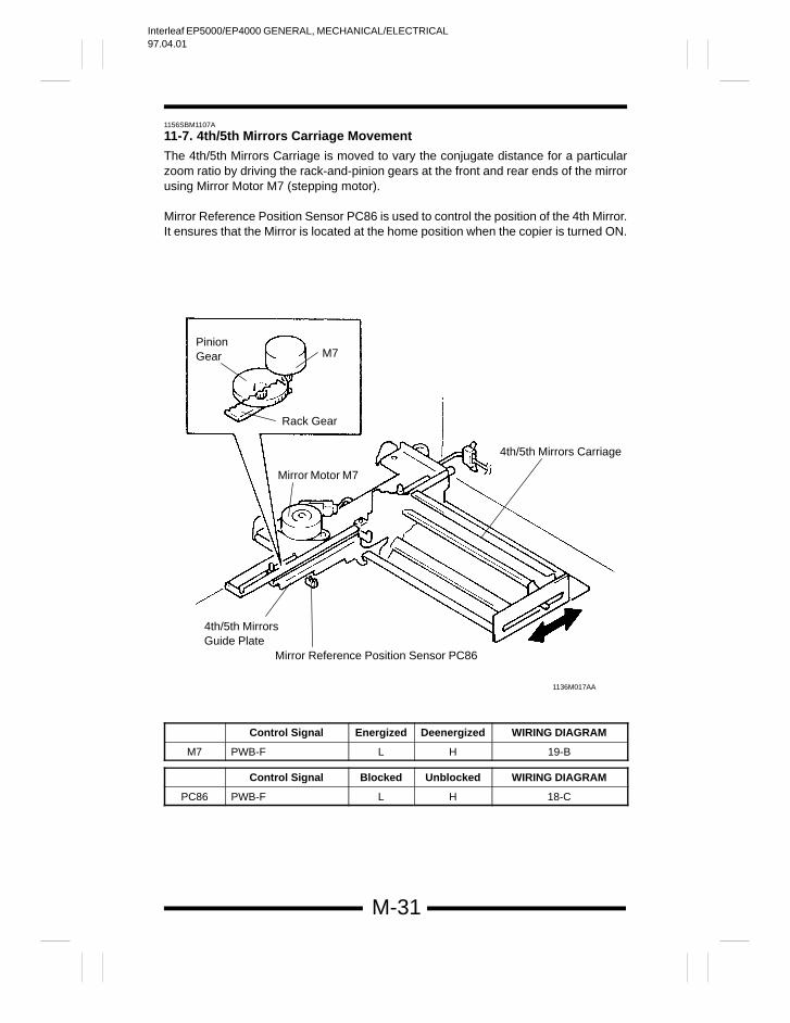
11-7. 4th/5th Mirrors Carriage Movement
The 4th/5th Mirrors Carriage is moved to vary the conjugate distance for a particularzoom ratio by driving the rack-and-pinion gears at the front and rear ends of the mirrorusing Mirror Motor M7 (stepping motor).
Mirror Reference Position Sensor PC86 is used to control the position of the 4th Mirror.It ensures that the Mirror is located at the home position when the copier is turned ON.
PinionGear M7
Rack Gear
Mirror Motor M7
4th/5th Mirrors Carriage
4th/5th MirrorsGuide Plate
Mirror Reference Position Sensor PC86
1136M017AA
Control Signal Energized Deenergized WIRING DIAGRAM
M7 PWB-F L H 19-B
Control Signal Blocked Unblocked WIRING DIAGRAM
PC86 PWB-F L H 18-C
Interleaf EP5000/EP4000 GENERAL, MECHANICAL/ELECTRICAL97.04.01
M-32
1156SBM1108A
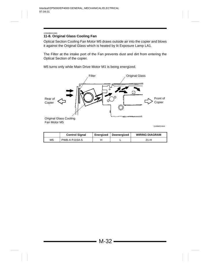
11-8. Original Glass Cooling Fan
Optical Section Cooling Fan Motor M5 draws outside air into the copier and blowsit against the Original Glass which is heated by lit Exposure Lamp LA1.
The Filter at the intake port of the Fan prevents dust and dirt from entering theOptical Section of the copier.
M5 turns only while Main Drive Motor M1 is being energized.
Rear of Copier
Filter
Front of Copier
Original Glass
Original Glass Cooling Fan Motor M5
1149M024AA
Control Signal Energized Deenergized WIRING DIAGRAM
M5 PWB-A PJ15A-5 H L 21-H
Interleaf EP5000/EP4000 GENERAL, MECHANICAL/ELECTRICAL97.04.01
M-33
1156SBM1200A
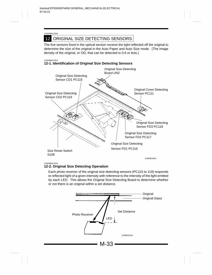
ORIGINAL SIZE DETECTING SENSORS12The five sensors fixed in the optical section receive the light reflected off the original todetermine the size of the original in the Auto Paper and Auto Size mode. (The imagedensity of the original, or OD, that can be detected is 0.6 or less.)
1156SBM1201A
12-1. Identification of Original Size Detecting Sensors
Original Size Detecting
Sensor FD1 PC116
1136M018AA
Original Cover Detecting Sensor PC111
Original Size Detecting Sensor CD1 PC115
Original Size Detecting Sensor CD2 PC119
Size Reset Switch S108
Original Size Detecting Board UN2
Original Size Detecting Sensor FD2 PC117
Original Size Detecting Sensor FD3 PC118
1156SBM1202A
12-2. Original Size Detecting Operation
Each photo receiver of the original size detecting sensors (PC115 to 119) respondsto reflected light of a given intensity with reference to the intensity of the light emittedby each LED. This allows the Original Size Detecting Board to determine whetheror not there is an original within a set distance.
1136M020AA
OriginalOriginal Glass
Set Distance
LEDPhoto Receiver
Interleaf EP5000/EP4000 GENERAL, MECHANICAL/ELECTRICAL97.04.01
M-34
1156SBM1203A
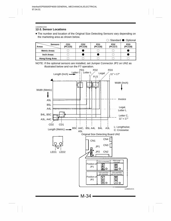
12-3. Sensor Locations
The number and location of the Original Size Detecting Sensors vary depending onthe marketing area as shown below.
: Standard : Optional
SensorsAreas
CD1(PC115)
CD2(PC119)
FD1(PC116)
FD2(PC117)
FD3(PC118)
Metric Areas
Inch Areas
Hong Kong Area
NOTE: If the optional sensors are installed, set Jumper Connector JP2 on UN2 as illustrated below and run the F7 operation.
1136M022CA
FD1
A4C,A5L
B5C B5L A4L B4L A3L
CN1
JP1
JP2 CN2
CN3
CN4
Original Size Detecting Board UN2
Length (Metric)
LED1 LED2
Letter C Letter L
FLSLegal
FD2 FD3
11”17”Length (Inch)
Width (Metric)
A5L
B5L
A4L
B4L, B5C
A3L, A4C
CD2 CD1
Width (Inch)
Invoice
Legal,Letter L
Letter C,11”17”
L: Lengthwise;C: Crosswise
Position of JP1
FD1 is notmounted
Position of JP2
FD1 is mounted
CD2 and FD3are mounted
CD2 and FD3are not mounted
Interleaf EP5000/EP4000 GENERAL, MECHANICAL/ELECTRICAL97.04.01
M-35
1156SBM1204A
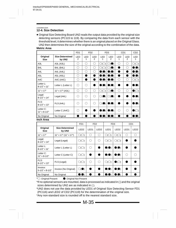
12-4. Size Detection
Original Size Detecting Board UN2 reads the output data provided by the original sizedetecting sensors (PC115 to 119). By comparing the data from each sensor with thethreshold level, it determines whether there is an original placed on the Original Glass.UN2 then determines the size of the original according to the combination of the data.
Metric Area
FD1 FD2 FD3 CD1 CD2
OriginalSize
Size Determinedby UN2
LED2
LED1
LED2
LED1
LED2
LED1
LED2
LED1
A3L A3L (A3L) () () ()
B4L B4L (B4L) () () ()
A4L A4L (A4L) () () ()
A5L A5L (A5L) () () ()
A4C A4C (A4C) () () ()
Letter L:8-1/2”11”
Letter L (Letter L) () () ()
11”17” 11”17” (A3L) () () ()
Legal:8-1/2”14”
Legal (A4L) () () ()
FLS:8-1/2”13”
FLS (A4L) () () ()
Letter C:11”8-1/2”
Letter C (A4C) () () ()
No Original No Original () () ()
Inch Area
FD1 FD2 FD3 CD1
Original Size
Size Determinedby UN2
LED2 LED1 LED2 LED1 LED2 LED1 LED2
11”17” 11”17” (11”17”) () () ()
Legal: 8-1/2”14”
Legal (Legal) () () ()
Letter L: 8-1/2”11”
Letter L (Letter L) () () ()
Letter C: 11”8-1/2”
Letter C (Letter C) () () ()
FLS: 8-1/2”13”
FLS (Legal) () () ()
Invoice:5-1/2”8-1/2”
Invoice (No Original) () () ()
No Original No Original () () ()
*: Original Present : Original Not Present
*If no optional sensors are mounted, data is processed as indicated in ( ) and the originalsizes determined by UN2 are as indicated in ( ).
*UN2 does not use the data provided by LED1 of Original Size Detecting Sensor FD1(PC116) and LED2 of CD2 (PC119) for the determination of the original size.
*Any non-standard size is rounded off to the nearest standard size.
Interleaf EP5000/EP4000 GENERAL, MECHANICAL/ELECTRICAL97.04.01
M-36
1156SBM1205A
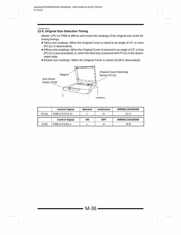
12-5. Original Size Detection Timing
Master CPU on PWB-A affirms and resets the readings of the original size at the fol-lowing timings. Takes size readings: When the Original Cover is raised to an angle of 15° or more
(PC111 is deactivated). Affirms size readings: When the Original Cover is lowered to an angle of 15° or less
(PC111 is just activated); or, when the Start key is pressed with PC111 in the deacti-vated state.
Resets size readings: When the Original Cover is raised (S108 is deactuated).
Magnet
Size Reset Switch S108
Original Cover DetectingSensor PC111
Control Signal Blocked Unblocked WIRING DIAGRAM
PC111 PWB-A PJ17A-11 L H 21-G
Control Signal ON OFF WIRING DIAGRAM
S108 PWB-A PJ12A-1 L H 16-B
Interleaf EP5000/EP4000 GENERAL, MECHANICAL/ELECTRICAL97.04.01
M-37
1156SBM1300A
DEVELOPING UNIT13
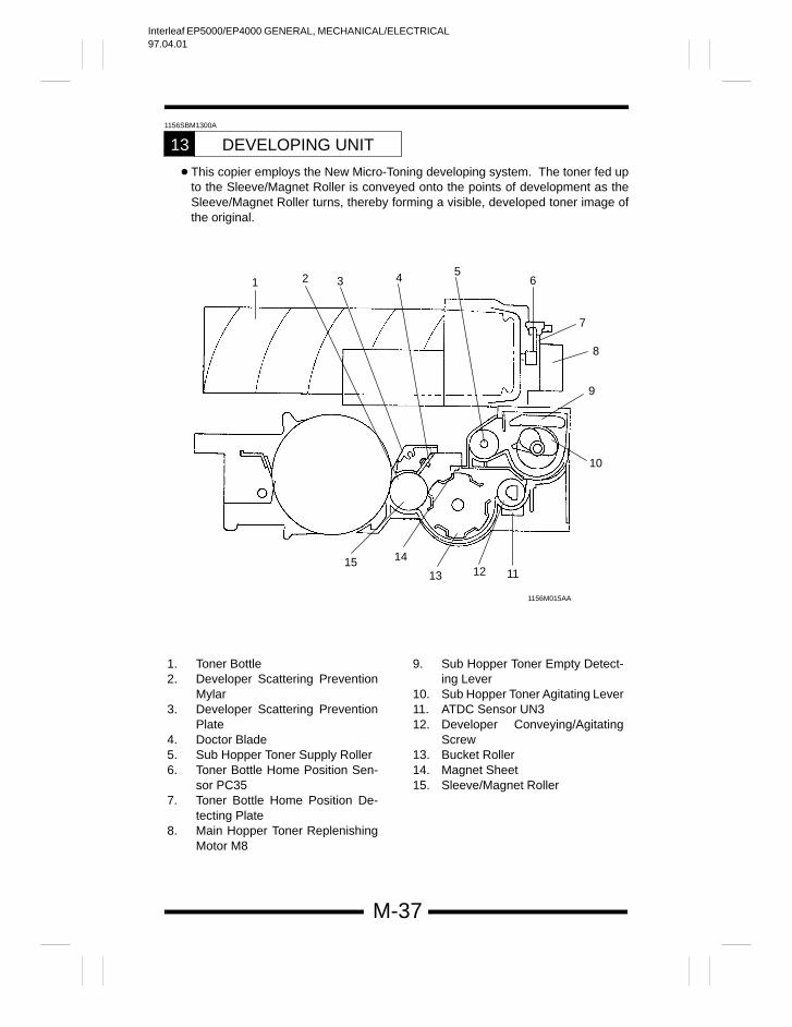
This copier employs the New Micro-Toning developing system. The toner fed upto the Sleeve/Magnet Roller is conveyed onto the points of development as theSleeve/Magnet Roller turns, thereby forming a visible, developed toner image ofthe original.
1156M015AA
1 2 3 4 56
7
8
9
10
111213
1415
1. Toner Bottle2. Developer Scattering Prevention
Mylar3. Developer Scattering Prevention
Plate4. Doctor Blade5. Sub Hopper Toner Supply Roller6. Toner Bottle Home Position Sen-
sor PC357. Toner Bottle Home Position De-
tecting Plate8. Main Hopper Toner Replenishing
Motor M8
9. Sub Hopper Toner Empty Detect-ing Lever
10. Sub Hopper Toner Agitating Lever11. ATDC Sensor UN312. Developer Conveying/Agitating
Screw13. Bucket Roller14. Magnet Sheet15. Sleeve/Magnet Roller
Interleaf EP5000/EP4000 GENERAL, MECHANICAL/ELECTRICAL97.04.01
M-38
1156SBM1301A
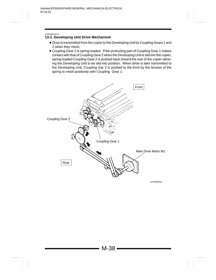
13-1. Developing Unit Drive Mechanism
Drive is transmitted from the copier to the Developing Unit by Coupling Gears 1 and2 when they mesh.
Coupling Gear 2 is spring-loaded. If the protruding part of Coupling Gear 1 makescontact with that of Coupling Gear 2 when the Developing Unit is slid into the copier,spring-loaded Coupling Gear 2 is pushed back toward the rear of the copier allow-ing the Developing Unit to be slid into position. When drive is later transmitted tothe Developing Unit, Coupling Gar 2 is pushed to the front by the tension of thespring to mesh positively with Coupling Gear 1.
1134M009AA
Coupling Gear 2
Coupling Gear 1
Main Drive Motor M1
Rear
Front
Interleaf EP5000/EP4000 GENERAL, MECHANICAL/ELECTRICAL97.04.01
M-39
1156SBM1302A
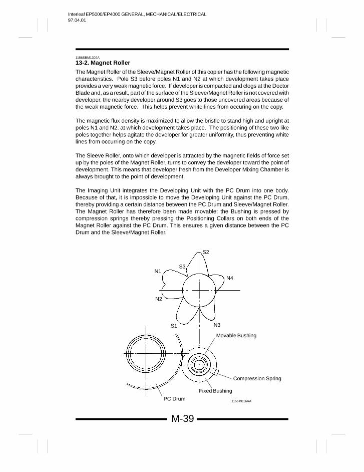
13-2. Magnet Roller
The Magnet Roller of the Sleeve/Magnet Roller of this copier has the following magneticcharacteristics. Pole S3 before poles N1 and N2 at which development takes placeprovides a very weak magnetic force. If developer is compacted and clogs at the DoctorBlade and, as a result, part of the surface of the Sleeve/Magnet Roller is not covered withdeveloper, the nearby developer around S3 goes to those uncovered areas because ofthe weak magnetic force. This helps prevent white lines from occuring on the copy.
The magnetic flux density is maximized to allow the bristle to stand high and upright atpoles N1 and N2, at which development takes place. The positioning of these two likepoles together helps agitate the developer for greater uniformity, thus preventing whitelines from occurring on the copy.
The Sleeve Roller, onto which developer is attracted by the magnetic fields of force setup by the poles of the Magnet Roller, turns to convey the developer toward the point ofdevelopment. This means that developer fresh from the Developer Mixing Chamber isalways brought to the point of development.
The Imaging Unit integrates the Developing Unit with the PC Drum into one body.Because of that, it is impossible to move the Developing Unit against the PC Drum,thereby providing a certain distance between the PC Drum and Sleeve/Magnet Roller.The Magnet Roller has therefore been made movable: the Bushing is pressed bycompression springs thereby pressing the Positioning Collars on both ends of theMagnet Roller against the PC Drum. This ensures a given distance between the PCDrum and the Sleeve/Magnet Roller.
Movable Bushing
Compression Spring
Fixed Bushing
PC Drum 1156M016AA
N1
N2
N3
N4
S1
S2
S3
Interleaf EP5000/EP4000 GENERAL, MECHANICAL/ELECTRICAL97.04.01
M-40
1156SBM1303A
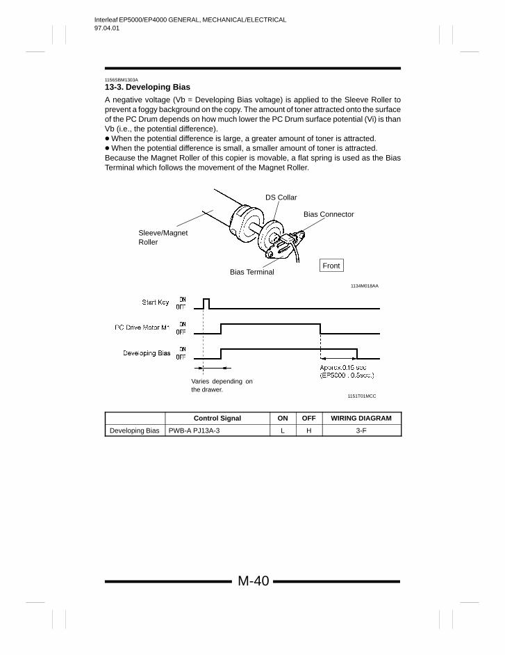
13-3. Developing Bias
A negative voltage (Vb = Developing Bias voltage) is applied to the Sleeve Roller toprevent a foggy background on the copy. The amount of toner attracted onto the surfaceof the PC Drum depends on how much lower the PC Drum surface potential (Vi) is thanVb (i.e., the potential difference). When the potential difference is large, a greater amount of toner is attracted. When the potential difference is small, a smaller amount of toner is attracted.Because the Magnet Roller of this copier is movable, a flat spring is used as the BiasTerminal which follows the movement of the Magnet Roller.
Sleeve/MagnetRoller
Bias Connector
1151T01MCC
Bias Terminal
DS Collar
1134M018AA
Front
Varies depending onthe drawer.
Control Signal ON OFF WIRING DIAGRAM
Developing Bias PWB-A PJ13A-3 L H 3-F
Interleaf EP5000/EP4000 GENERAL, MECHANICAL/ELECTRICAL97.04.01
M-41
1156SBM1304A
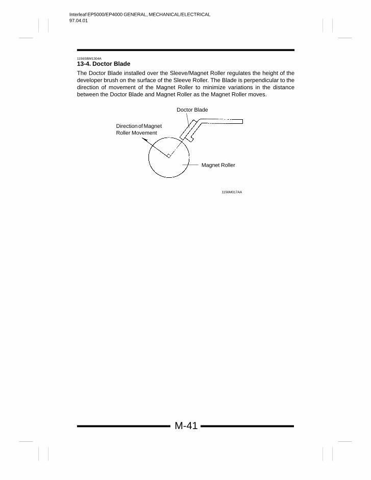
13-4. Doctor Blade
The Doctor Blade installed over the Sleeve/Magnet Roller regulates the height of thedeveloper brush on the surface of the Sleeve Roller. The Blade is perpendicular to thedirection of movement of the Magnet Roller to minimize variations in the distancebetween the Doctor Blade and Magnet Roller as the Magnet Roller moves.
Doctor Blade
Direction of MagnetRoller Movement
Magnet Roller
1156M017AA
Interleaf EP5000/EP4000 GENERAL, MECHANICAL/ELECTRICAL97.04.01
M-42
1156SBM1305A
13-5. ATDC Sensor
The copier compares the toner-to-carrier ratio (T/C) of the developer in the DeveloperMixing Chamber detected by ATDC Sensor UN3 during a copy cycle with the referenceratio (6%) and, if it finds a lower ratio than the reference, replenishes the supply of toner.The standard output voltage of the ATDC Sensor for the reference T/C (6%) is 2.5V.
If the toner-to-carrier ratio becomes lower than 2.5% in a toner-empty condition, thecopier inhibits the initiation of a new copy cycle (this feature can be enabled or disabledby a Tech. Rep. Choice mode). As soon as a ratio of 3% or more is recovered, the copierpermits the initiation of a new copy cycle.
If the Front Door is swung open and closed with a T/C ratio of less than 3%, the copierinitiates an Auxiliary Toner Replenishing sequence. (The toner-empty condition iscanceled as soon as a T/C ratio of 3.5% is reached and the copier completes theAuxiliary Toner Replenishing sequence when the target level is reached.)
ATDC Sensor Automatic AdjustmentAn automatic adjustment of the ATDC Sensor is made in the F8 or FF Test Modeoperation.
*When F8 (or FF) is Run after Starter Has Been Changed:Following the execution of the starter setup mode, upon pressing the Start Key, thecopier CPU reads the output value of the ATDC Sensor and adjusts the ATDCSensor gain so that the output value becomes 2.5V.
NOTE: If an F8 (or FF) operation is run at a time when the starter has not been changed,it can result in a wrong T/C reference value being set by the copier. Avoid casualuse of F8.
If the setting value has been cleared because of the RAM Board being replaced,use the “Level History” function of the Tech. Rep. mode to return the “ATDC Ref.Value” to the original value before the board was replaced.
Controlled Part Control Signal T/C Ratio StandardOutput Voltage
WIRING DIA-GRAM
UN3 PJ11A-2B 6.0(%) 2.5(V) 1-J
Interleaf EP5000/EP4000 GENERAL, MECHANICAL/ELECTRICAL97.04.01
M-43
<Toner Replenishing Control by ATDC Sensor>
The ATDC Sensor samples T/C for each copy and the copier compares the reading withthe reference T/C (which is normally 6% but may 7% depending on the imagestabilization control provided), energizing Sub Hopper Toner Replenishing Motor M9 asmay be necessary to replenish toner in either of the following four modes.
Toner Replenishing Mode Conditions Amount Replen-ished *
Large amount replenishing The ATDC Sensor reading is lower than
reference T/C by 0.5% or more.
Approx. 133 mg
Small amount replenishing The ATDC Sensor reading is lower than
reference T/C by less than 0.5%.
Approx. 66 mg
Fixed amount replenishing The ATDC Sensor reading is higher than
reference T/C by less than 1%.
Approx. 13mg
No toner replenishing The ATDC Sensor reading is higher than
reference T/C by 1% or more.
* The amount of toner replenished varies according to the paper size (given in the tableare figures for A4). The copier is also provided with a function that, if T/C detectedduring a copy cycle is lower than the reference by 2% or more, interrupts the copycycle and performs a toner replenishing sequence and, as soon as there is a gain of1% against the T/C reading, resumes the copy cycle. This function is, however, dis-abled when a toner-empty condition is detected and the ATDC Sensor is found faulty.
<Toner Replenishing Control by AIDC Sensor>
This copier is equipped with a function that switches from the ATDC Sensor, if it becomesdefective, to the AIDC Sensor to continue providing the toner replenishing control. Apattern is produced on the surface of the PC Drum for each copy between twosuccessive copies or after it has been fed out. The AIDC Sensor reads that pattern todetect the amount of toner sticking to it and the copier performs either of the followingtoner replenishing sequences depending on the output voltage of the AIDC Sensor.(Controlled target T/C: 6%; AIDC Sensor output voltage: DC4.25V)
Toner Replenishing Mode AIDC Sensor Output Volt-age
Amount Replenished *
Large amount replenishing Less than DC3.25V Approx. 129 mg
Small amount replenishing DC3.25V to less than 4.25V Approx. 64 mg
Fixed amount replenishing DC4.25V to less than 5.25V Approx. 13 mg
No toner replenishing DC5.25V or more
* The amount of toner replenished varies according to the paper size (given in the tableare figures for A4).
Interleaf EP5000/EP4000 GENERAL, MECHANICAL/ELECTRICAL97.04.01
M-44
1156SBM1306A
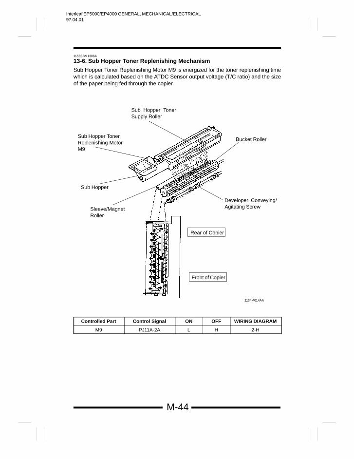
13-6. Sub Hopper Toner Replenishing Mechanism
Sub Hopper Toner Replenishing Motor M9 is energized for the toner replenishing timewhich is calculated based on the ATDC Sensor output voltage (T/C ratio) and the sizeof the paper being fed through the copier.
Sub Hopper TonerReplenishing MotorM9
Sub Hopper TonerSupply Roller
Bucket Roller
Developer Conveying/Agitating Screw
Sub Hopper
Sleeve/MagnetRoller
Rear of Copier
Front of Copier
1134M014AA
Controlled Part Control Signal ON OFF WIRING DIAGRAM
M9 PJ11A-2A L H 2-H
Interleaf EP5000/EP4000 GENERAL, MECHANICAL/ELECTRICAL97.04.01
M-45
1156SBM1307A
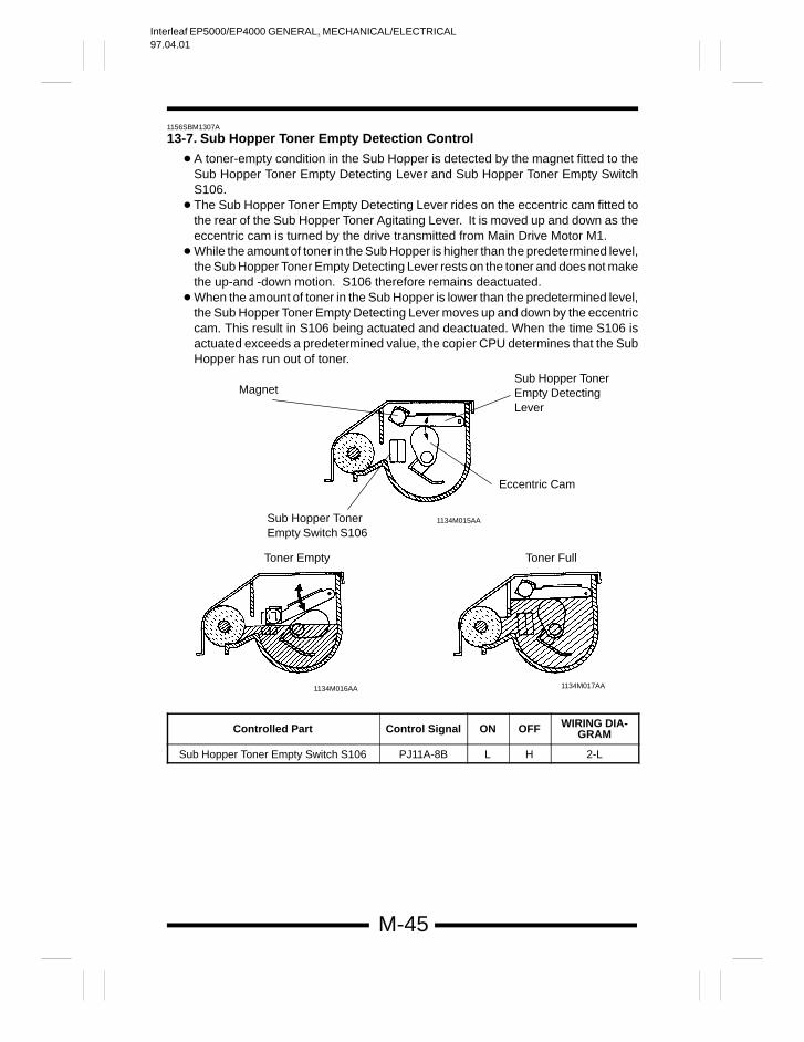
13-7. Sub Hopper Toner Empty Detection Control
A toner-empty condition in the Sub Hopper is detected by the magnet fitted to theSub Hopper Toner Empty Detecting Lever and Sub Hopper Toner Empty SwitchS106.
The Sub Hopper Toner Empty Detecting Lever rides on the eccentric cam fitted tothe rear of the Sub Hopper Toner Agitating Lever. It is moved up and down as theeccentric cam is turned by the drive transmitted from Main Drive Motor M1.
While the amount of toner in the Sub Hopper is higher than the predetermined level,the Sub Hopper Toner Empty Detecting Lever rests on the toner and does not makethe up-and -down motion. S106 therefore remains deactuated.
When the amount of toner in the Sub Hopper is lower than the predetermined level,the Sub Hopper Toner Empty Detecting Lever moves up and down by the eccentriccam. This result in S106 being actuated and deactuated. When the time S106 isactuated exceeds a predetermined value, the copier CPU determines that the SubHopper has run out of toner.
Sub Hopper TonerEmpty DetectingLever
Magnet
Eccentric Cam
Sub Hopper TonerEmpty Switch S106
1134M017AA1134M016AA
1134M015AA
Toner FullToner Empty
Controlled Part Control Signal ON OFF WIRING DIA-GRAM
Sub Hopper Toner Empty Switch S106 PJ11A-8B L H 2-L
Interleaf EP5000/EP4000 GENERAL, MECHANICAL/ELECTRICAL97.04.01
M-46
1156SBM1308A
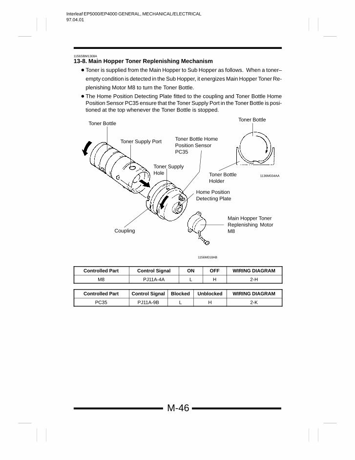
13-8. Main Hopper Toner Replenishing Mechanism
Toner is supplied from the Main Hopper to Sub Hopper as follows. When a toner–
empty condition is detected in the Sub Hopper, it energizes Main Hopper Toner Re-
plenishing Motor M8 to turn the Toner Bottle.
The Home Position Detecting Plate fitted to the coupling and Toner Bottle HomePosition Sensor PC35 ensure that the Toner Supply Port in the Toner Bottle is posi-tioned at the top whenever the Toner Bottle is stopped.
Toner BottleToner Bottle
Coupling
1156M018AB
1136M034AA
Toner Supply Port
Toner Supply Hole
Main Hopper Toner Replenishing MotorM8
Home Position Detecting Plate
Toner BottleHolder
Toner Bottle HomePosition SensorPC35
Controlled Part Control Signal ON OFF WIRING DIAGRAM
M8 PJ11A-4A L H 2-H
Controlled Part Control Signal Blocked Unblocked WIRING DIAGRAM
PC35 PJ11A-9B L H 2-K
Interleaf EP5000/EP4000 GENERAL, MECHANICAL/ELECTRICAL97.04.01
M-47
1156SBM1309A
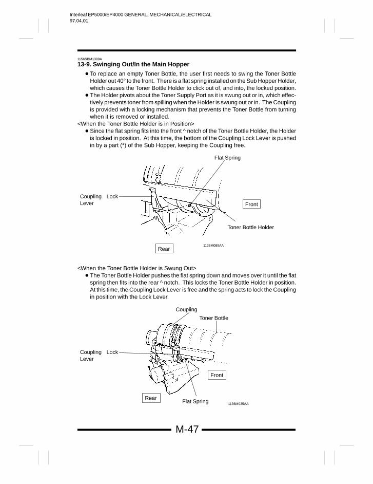
13-9. Swinging Out/In the Main Hopper
To replace an empty Toner Bottle, the user first needs to swing the Toner BottleHolder out 40° to the front. There is a flat spring installed on the Sub Hopper Holder,which causes the Toner Bottle Holder to click out of, and into, the locked position.
The Holder pivots about the Toner Supply Port as it is swung out or in, which effec-tively prevents toner from spilling when the Holder is swung out or in. The Couplingis provided with a locking mechanism that prevents the Toner Bottle from turningwhen it is removed or installed.
<When the Toner Bottle Holder is in Position> Since the flat spring fits into the front notch of the Toner Bottle Holder, the Holder
is locked in position. At this time, the bottom of the Coupling Lock Lever is pushedin by a part (*) of the Sub Hopper, keeping the Coupling free.
Rear
Front
1136M089AA
Flat Spring
Toner Bottle Holder
Coupling LockLever
<When the Toner Bottle Holder is Swung Out> The Toner Bottle Holder pushes the flat spring down and moves over it until the flat
spring then fits into the rear notch. This locks the Toner Bottle Holder in position.At this time, the Coupling Lock Lever is free and the spring acts to lock the Couplingin position with the Lock Lever.
Rear
Front
1136M035AA
Coupling
Toner Bottle
Coupling LockLever
Flat Spring
Interleaf EP5000/EP4000 GENERAL, MECHANICAL/ELECTRICAL97.04.01
M-48
1156SBM1400A
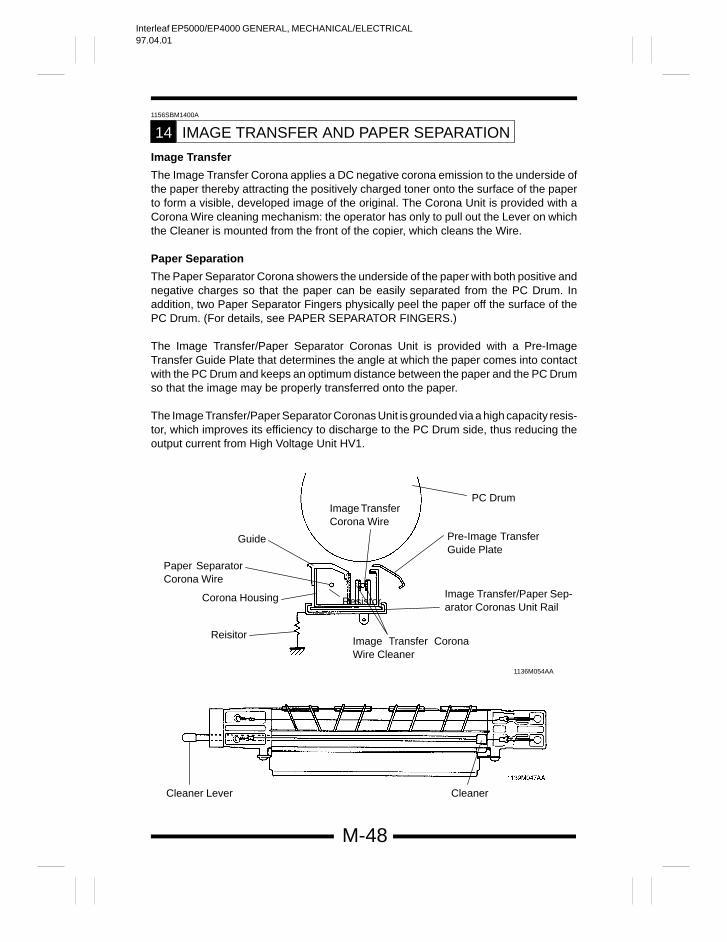
IMAGE TRANSFER AND PAPER SEPARATION14
Image Transfer
The Image Transfer Corona applies a DC negative corona emission to the underside ofthe paper thereby attracting the positively charged toner onto the surface of the paperto form a visible, developed image of the original. The Corona Unit is provided with aCorona Wire cleaning mechanism: the operator has only to pull out the Lever on whichthe Cleaner is mounted from the front of the copier, which cleans the Wire.
Paper Separation
The Paper Separator Corona showers the underside of the paper with both positive andnegative charges so that the paper can be easily separated from the PC Drum. Inaddition, two Paper Separator Fingers physically peel the paper off the surface of thePC Drum. (For details, see PAPER SEPARATOR FINGERS.)
The Image Transfer/Paper Separator Coronas Unit is provided with a Pre-ImageTransfer Guide Plate that determines the angle at which the paper comes into contactwith the PC Drum and keeps an optimum distance between the paper and the PC Drumso that the image may be properly transferred onto the paper.
The Image Transfer/Paper Separator Coronas Unit is grounded via a high capacity resis-tor, which improves its efficiency to discharge to the PC Drum side, thus reducing theoutput current from High Voltage Unit HV1.
Guide
Image Transfer CoronaWire Cleaner
Image TransferCorona Wire
Image Transfer/Paper Sep-arator Coronas Unit Rail
PC Drum
Cleaner Lever Cleaner
1136M054AA
Resistor
Pre-Image TransferGuide Plate
Paper SeparatorCorona Wire
Corona Housing
Reisitor
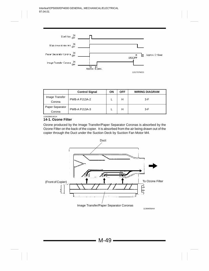
Interleaf EP5000/EP4000 GENERAL, MECHANICAL/ELECTRICAL97.04.01
M-49
1151T07MCD
Control Signal ON OFF WIRING DIAGRAM
Image Transfer
CoronaPWB-A PJ13A-2 L H 3-F
Paper Separator
CoronaPWB-A PJ13A-3 L H 3-F
1156SBM1401A
14-1. Ozone Filter
Ozone produced by the Image Transfer/Paper Separator Coronas is absorbed by theOzone Filter on the back of the copier. It is absorbed from the air being drawn out of thecopier through the Duct under the Suction Deck by Suction Fan Motor M4.
1136M056AA
(Front of Copier) To Ozone Filter
Image Transfer/Paper Separator Coronas
Duct
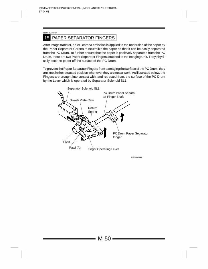
Interleaf EP5000/EP4000 GENERAL, MECHANICAL/ELECTRICAL97.04.01
M-50
1156SBM1500A
PAPER SEPARATOR FINGERS15
After image transfer, an AC corona emission is applied to the underside of the paper bythe Paper Separator Corona to neutralize the paper so that it can be easily separatedfrom the PC Drum. To further ensure that the paper is positively separated from the PCDrum, there are two Paper Separator Fingers attached to the Imaging Unit. They physi-cally peel the paper off the surface of the PC Drum.
To prevent the Paper Separator Fingers from damaging the surface of the PC Drum, theyare kept in the retracted position whenever they are not at work. As illustrated below, theFingers are brought into contact with, and retracted from, the surface of the PC Drumby the Lever which is operated by Separator Solenoid SL1.
Finger Operating Lever
Pivot
Pawl (A)
Separator Solenoid SL1
PC Drum Paper Separa-tor Finger Shaft
Swash Plate Cam
ReturnSpring
PC Drum Paper SeparatorFinger
1136M064AA
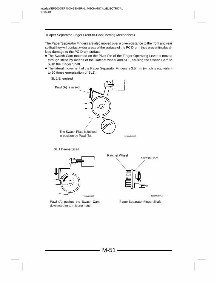
Interleaf EP5000/EP4000 GENERAL, MECHANICAL/ELECTRICAL97.04.01
M-51
<Paper Separator Finger Front-to-Back Moving Mechanism>
The Paper Separator Fingers are also moved over a given distance to the front and rearso that they will contact wider areas of the surface of the PC Drum, thus preventing local-ized damage to the PC Drum surface. The Swash Cam mounted on the Pivot Pin of the Finger Operating Lever is moved
through steps by means of the Ratchet wheel and SL1, causing the Swash Cam topush the Finger Shaft.
The lateral movement of the Paper Separator Fingers is 3.5 mm (which is equivalentto 60 times energization of SL1).
SL 1 Energized
Pawl (A) is raised.
The Swash Plate is lockedin position by Pawl (B). 1136M065AA
SL 1 Deenergized
Pawl (A) pushes the Swash Camdownward to turn it one notch.
Ratchet WheelSwash Cam
Paper Separator Finger Shaft
1136M067AA1136M066AA
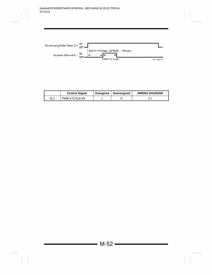
Interleaf EP5000/EP4000 GENERAL, MECHANICAL/ELECTRICAL97.04.01
M-52
Control Signal Energized Deenergized WIRING DIAGRAM
SL1 PWB-A PJ11A-6A L H 2-I
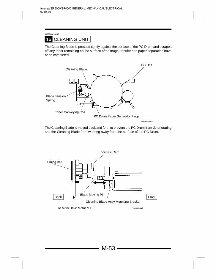
Interleaf EP5000/EP4000 GENERAL, MECHANICAL/ELECTRICAL97.04.01
M-53
1156SBM1600A
CLEANING UNIT16
The Cleaning Blade is pressed tightly against the surface of the PC Drum and scrapesoff any toner remaining on the surface after image transfer and paper separation havebeen completed.
Blade TensionSpring
Toner Conveying Coll
PC Unit
PC Drum Paper Separator Finger
1134M027AA
Cleaning Blade
The Cleaning Blade is moved back and forth to prevent the PC Drum from deterioratingand the Cleaning Blade from warping away from the surface of the PC Drum.
Timing Belt
Eccentric Cam
Blade Moving Pin
Cleaning Blade Assy Mounting Bracket
To Main Drive Motor M1 1134M028AA
Back Front
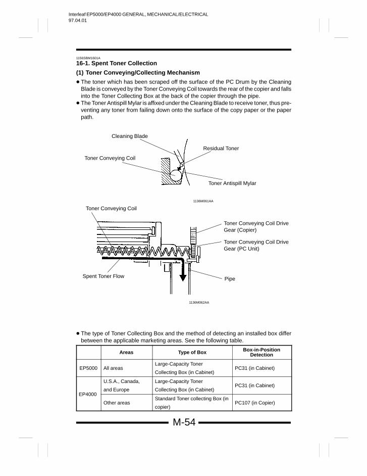
Interleaf EP5000/EP4000 GENERAL, MECHANICAL/ELECTRICAL97.04.01
M-54
1156SBM1601A
16-1. Spent Toner Collection
(1) Toner Conveying/Collecting Mechanism
The toner which has been scraped off the surface of the PC Drum by the CleaningBlade is conveyed by the Toner Conveying Coil towards the rear of the copier and fallsinto the Toner Collecting Box at the back of the copier through the pipe.
The Toner Antispill Mylar is affixed under the Cleaning Blade to receive toner, thus pre-venting any toner from failing down onto the surface of the copy paper or the paperpath.
Toner Conveying Coil
1136M061AA
1136M062AA
Cleaning Blade
Toner Conveying Coil
Residual Toner
Toner Antispill Mylar
Spent Toner Flow
Toner Conveying Coil DriveGear (Copier)
Toner Conveying Coil DriveGear (PC Unit)
Pipe
The type of Toner Collecting Box and the method of detecting an installed box differbetween the applicable marketing areas. See the following table.
Areas Type of Box Box-in-PositionDetection
EP5000 All areasLarge-Capacity Toner
Collecting Box (in Cabinet)PC31 (in Cabinet)
U.S.A., Canada,
and Europe
Large-Capacity Toner
Collecting Box (in Cabinet)PC31 (in Cabinet)
EP4000
Other areasStandard Toner collecting Box (in
copier)PC107 (in Copier)
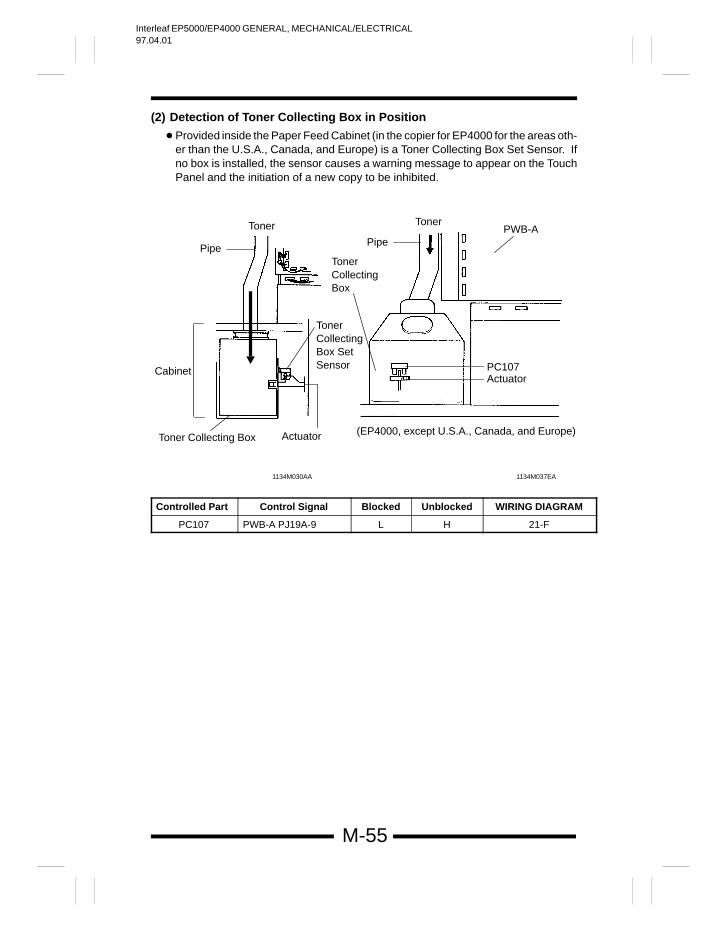
Interleaf EP5000/EP4000 GENERAL, MECHANICAL/ELECTRICAL97.04.01
M-55
(2) Detection of Toner Collecting Box in Position
Provided inside the Paper Feed Cabinet (in the copier for EP4000 for the areas oth-er than the U.S.A., Canada, and Europe) is a Toner Collecting Box Set Sensor. Ifno box is installed, the sensor causes a warning message to appear on the TouchPanel and the initiation of a new copy to be inhibited.
1134M037EA1134M030AA
Toner
Pipe
ActuatorToner Collecting Box
Cabinet
(EP4000, except U.S.A., Canada, and Europe)
PC107Actuator
TonerCollectingBox
Pipe
TonerPWB-A
TonerCollectingBox SetSensor
Controlled Part Control Signal Blocked Unblocked WIRING DIAGRAM
PC107 PWB-A PJ19A-9 L H 21-F
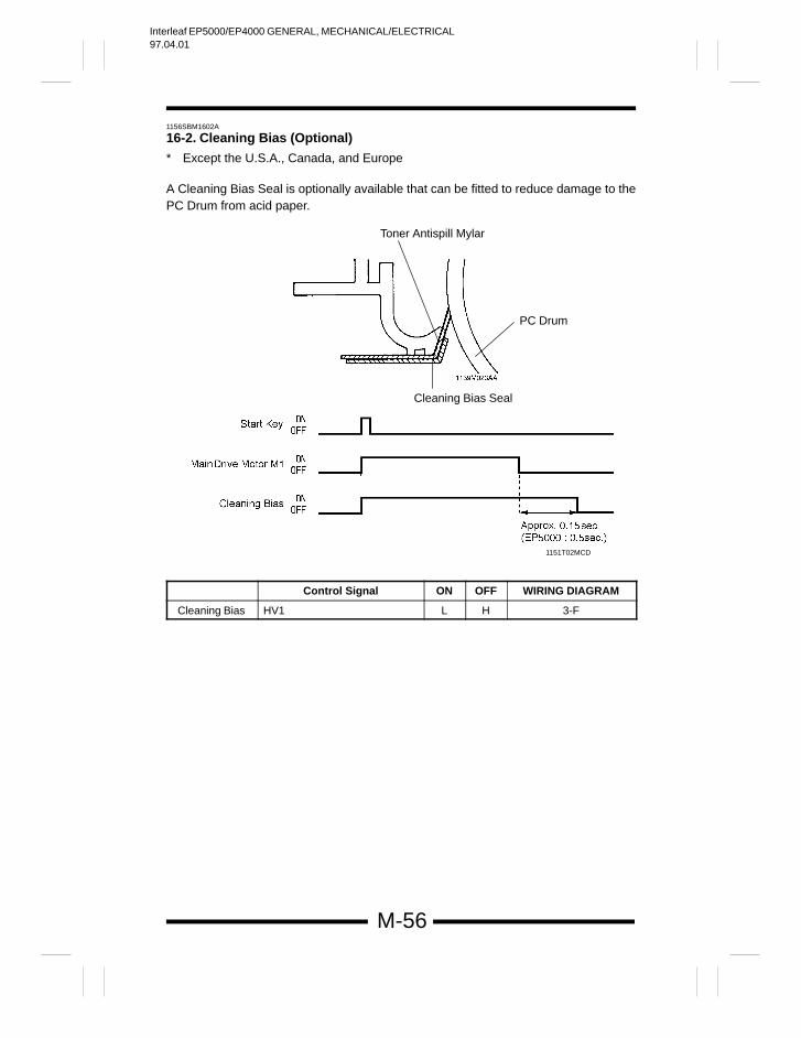
Interleaf EP5000/EP4000 GENERAL, MECHANICAL/ELECTRICAL97.04.01
M-56
1156SBM1602A
16-2. Cleaning Bias (Optional)
* Except the U.S.A., Canada, and Europe
A Cleaning Bias Seal is optionally available that can be fitted to reduce damage to thePC Drum from acid paper.
Toner Antispill Mylar
PC Drum
Cleaning Bias Seal
1151T02MCD
Control Signal ON OFF WIRING DIAGRAM
Cleaning Bias HV1 L H 3-F
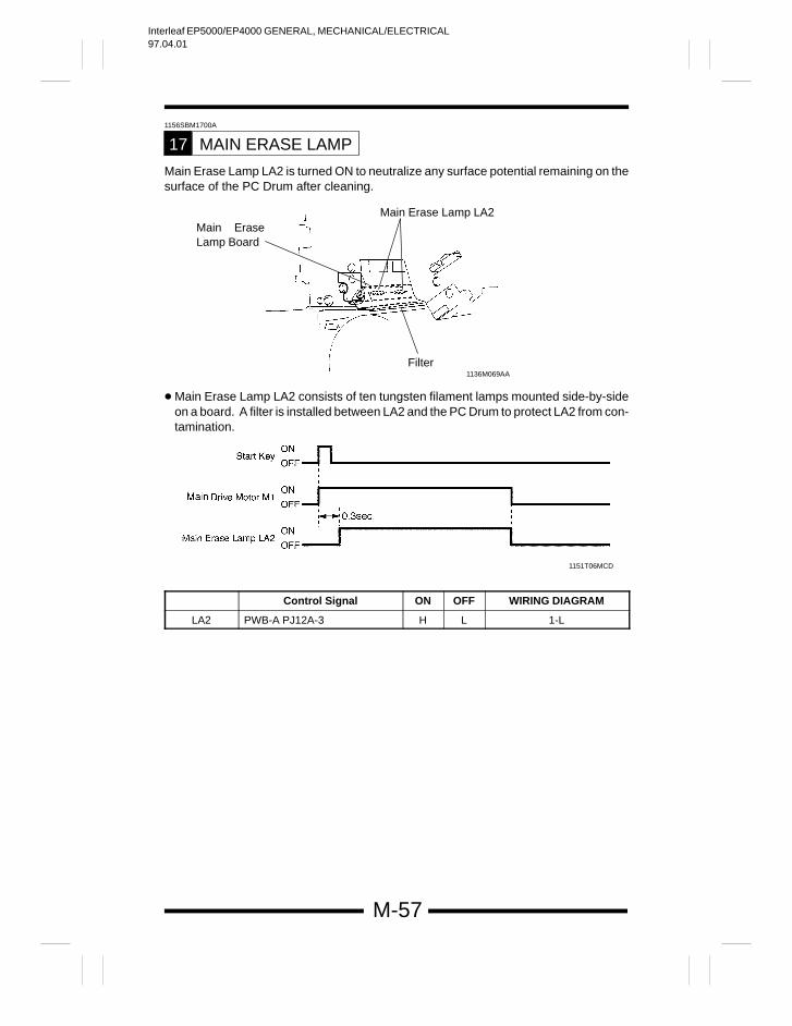
Interleaf EP5000/EP4000 GENERAL, MECHANICAL/ELECTRICAL97.04.01
M-57
1156SBM1700A
MAIN ERASE LAMP17
Main Erase Lamp LA2 is turned ON to neutralize any surface potential remaining on thesurface of the PC Drum after cleaning.
Main EraseLamp Board
Filter
Main Erase Lamp LA2
1136M069AA
Main Erase Lamp LA2 consists of ten tungsten filament lamps mounted side-by-sideon a board. A filter is installed between LA2 and the PC Drum to protect LA2 from con-tamination.
1151T06MCD
Control Signal ON OFF WIRING DIAGRAM
LA2 PWB-A PJ12A-3 H L 1-L
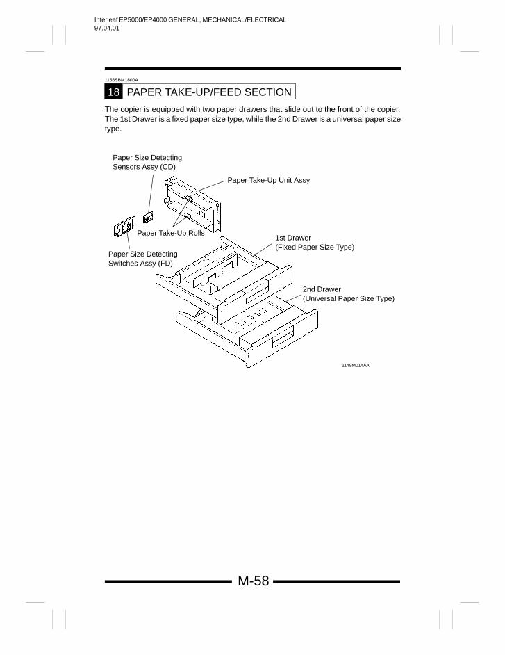
Interleaf EP5000/EP4000 GENERAL, MECHANICAL/ELECTRICAL97.04.01
M-58
1156SBM1800A
PAPER TAKE-UP/FEED SECTION18
The copier is equipped with two paper drawers that slide out to the front of the copier.The 1st Drawer is a fixed paper size type, while the 2nd Drawer is a universal paper sizetype.
1149M014AA
Paper Size Detecting Sensors Assy (CD)
Paper Size Detecting Switches Assy (FD)
Paper Take-Up Rolls
Paper Take-Up Unit Assy
2nd Drawer (Universal Paper Size Type)
1st Drawer (Fixed Paper Size Type)
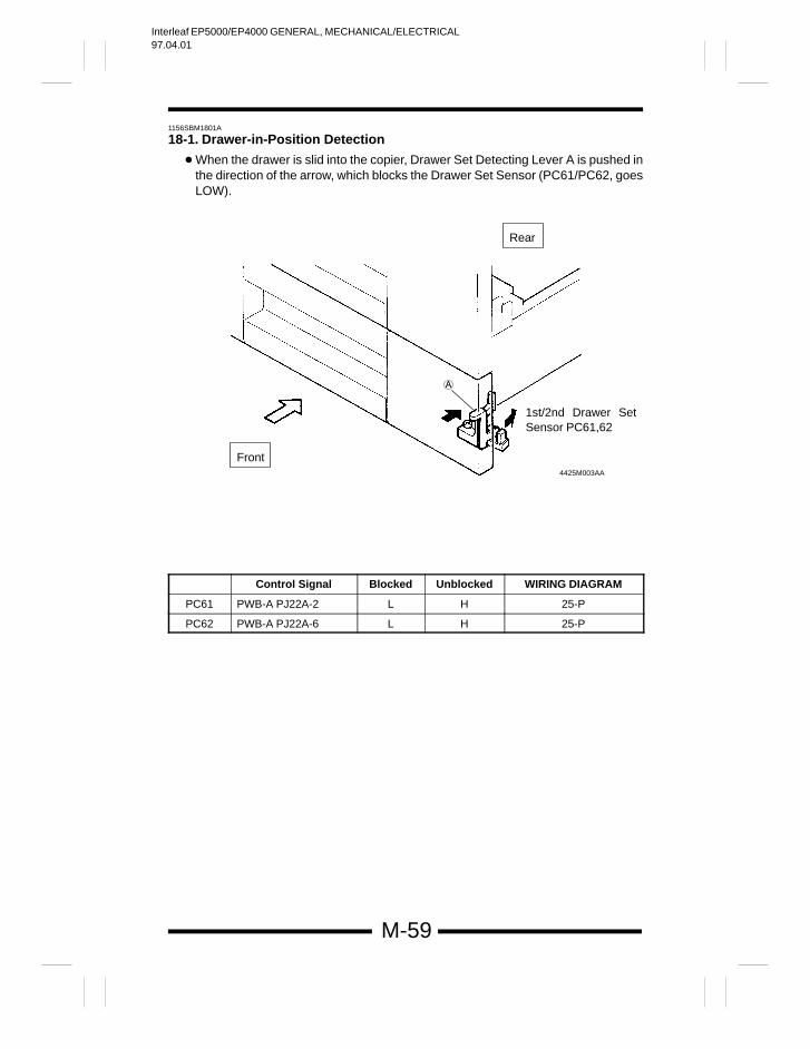
Interleaf EP5000/EP4000 GENERAL, MECHANICAL/ELECTRICAL97.04.01
M-59
1156SBM1801A
18-1. Drawer-in-Position Detection
When the drawer is slid into the copier, Drawer Set Detecting Lever A is pushed inthe direction of the arrow, which blocks the Drawer Set Sensor (PC61/PC62, goesLOW).
Rear
1st/2nd Drawer SetSensor PC61,62
4425M003AA
Front
Control Signal Blocked Unblocked WIRING DIAGRAM
PC61 PWB-A PJ22A-2 L H 25-P
PC62 PWB-A PJ22A-6 L H 25-P
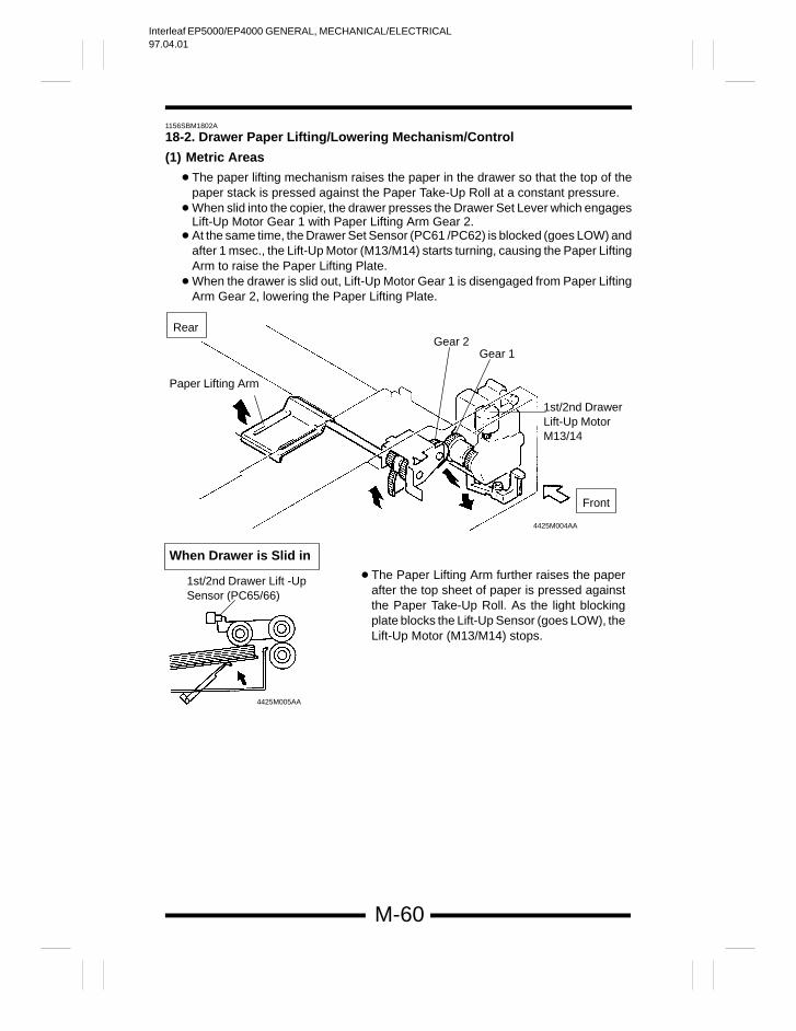
Interleaf EP5000/EP4000 GENERAL, MECHANICAL/ELECTRICAL97.04.01
M-60
1156SBM1802A
18-2. Drawer Paper Lifting/Lowering Mechanism/Control
(1) Metric Areas
The paper lifting mechanism raises the paper in the drawer so that the top of thepaper stack is pressed against the Paper Take-Up Roll at a constant pressure.
When slid into the copier, the drawer presses the Drawer Set Lever which engagesLift-Up Motor Gear 1 with Paper Lifting Arm Gear 2.
At the same time, the Drawer Set Sensor (PC61 /PC62) is blocked (goes LOW) andafter 1 msec., the Lift-Up Motor (M13/M14) starts turning, causing the Paper LiftingArm to raise the Paper Lifting Plate.
When the drawer is slid out, Lift-Up Motor Gear 1 is disengaged from Paper LiftingArm Gear 2, lowering the Paper Lifting Plate.
1st/2nd DrawerLift-Up MotorM13/14
Paper Lifting Arm
Gear 2Gear 1
4425M004AA
Rear
Front
When Drawer is Slid in
1st/2nd Drawer Lift -UpSensor (PC65/66)
4425M005AA
The Paper Lifting Arm further raises the paperafter the top sheet of paper is pressed againstthe Paper Take-Up Roll. As the light blockingplate blocks the Lift-Up Sensor (goes LOW), theLift-Up Motor (M13/M14) stops.
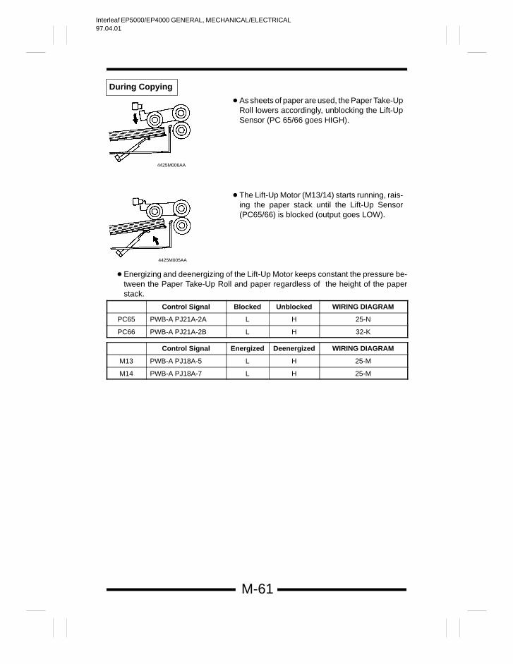
Interleaf EP5000/EP4000 GENERAL, MECHANICAL/ELECTRICAL97.04.01
M-61
4425M006AA
4425M005AA
As sheets of paper are used, the Paper Take-UpRoll lowers accordingly, unblocking the Lift-UpSensor (PC 65/66 goes HIGH).
The Lift-Up Motor (M13/14) starts running, rais-ing the paper stack until the Lift-Up Sensor(PC65/66) is blocked (output goes LOW).
During Copying
Energizing and deenergizing of the Lift-Up Motor keeps constant the pressure be-tween the Paper Take-Up Roll and paper regardless of the height of the paperstack.
Control Signal Blocked Unblocked WIRING DIAGRAM
PC65 PWB-A PJ21A-2A L H 25-N
PC66 PWB-A PJ21A-2B L H 32-K
Control Signal Energized Deenergized WIRING DIAGRAM
M13 PWB-A PJ18A-5 L H 25-M
M14 PWB-A PJ18A-7 L H 25-M
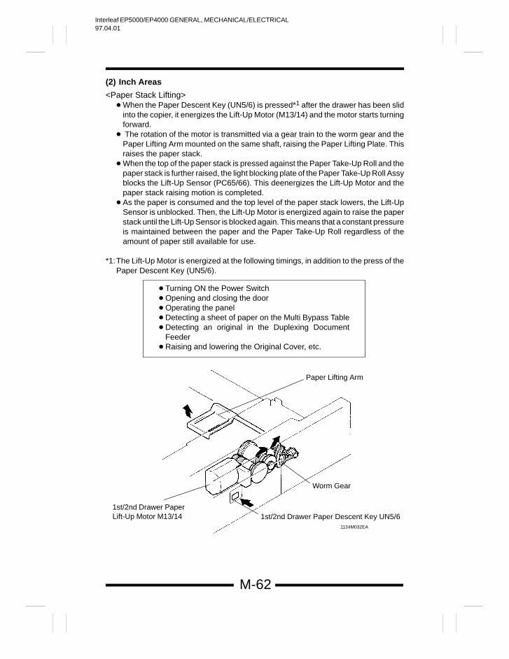
Interleaf EP5000/EP4000 GENERAL, MECHANICAL/ELECTRICAL97.04.01
M-62
(2) Inch Areas
<Paper Stack Lifting> When the Paper Descent Key (UN5/6) is pressed*1 after the drawer has been slid
into the copier, it energizes the Lift-Up Motor (M13/14) and the motor starts turningforward.
The rotation of the motor is transmitted via a gear train to the worm gear and thePaper Lifting Arm mounted on the same shaft, raising the Paper Lifting Plate. Thisraises the paper stack.
When the top of the paper stack is pressed against the Paper Take-Up Roll and thepaper stack is further raised, the light blocking plate of the Paper Take-Up Roll Assyblocks the Lift-Up Sensor (PC65/66). This deenergizes the Lift-Up Motor and thepaper stack raising motion is completed.
As the paper is consumed and the top level of the paper stack lowers, the Lift-UpSensor is unblocked. Then, the Lift-Up Motor is energized again to raise the paperstack until the Lift-Up Sensor is blocked again. This means that a constant pressureis maintained between the paper and the Paper Take-Up Roll regardless of theamount of paper still available for use.
*1:The Lift-Up Motor is energized at the following timings, in addition to the press of thePaper Descent Key (UN5/6).
Turning ON the Power Switch Opening and closing the door Operating the panel Detecting a sheet of paper on the Multi Bypass Table Detecting an original in the Duplexing Document
Feeder Raising and lowering the Original Cover, etc.
1st/2nd Drawer PaperLift-Up Motor M13/14
Paper Lifting Arm
1st/2nd Drawer Paper Descent Key UN5/6
Worm Gear
1134M032EA
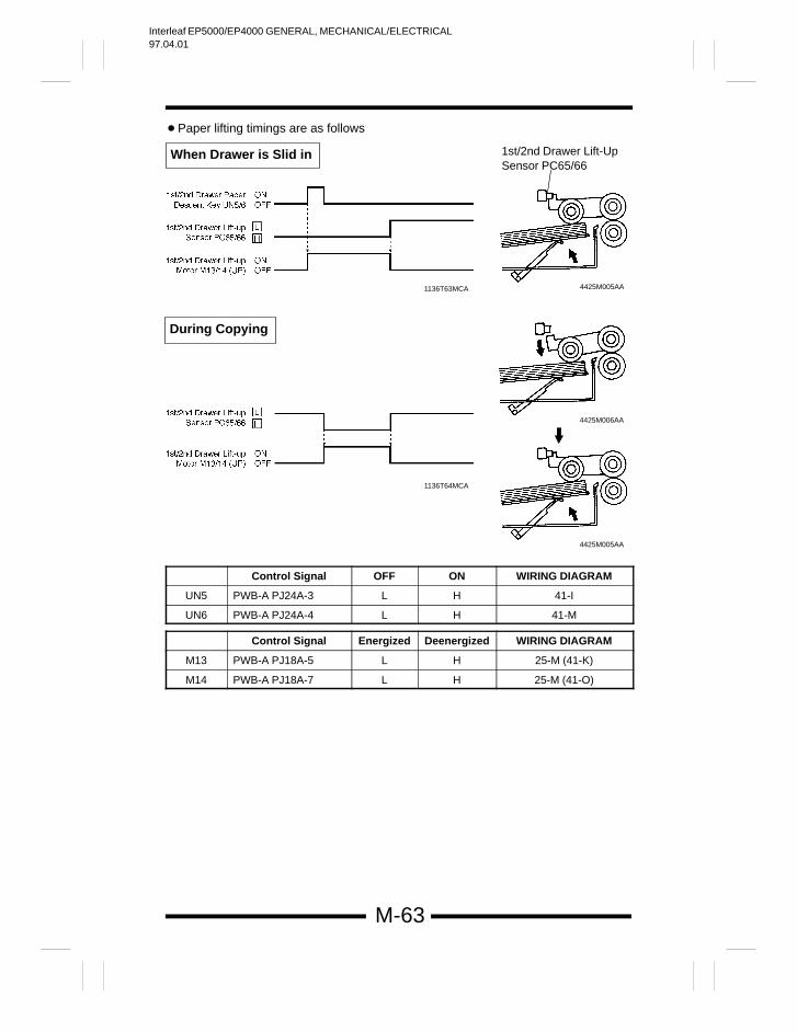
Interleaf EP5000/EP4000 GENERAL, MECHANICAL/ELECTRICAL97.04.01
M-63
Paper lifting timings are as follows
1st/2nd Drawer Lift-UpSensor PC65/66
4425M005AA
4425M006AA
4425M005AA
1136T63MCA
1136T64MCA
During Copying
When Drawer is Slid in
Control Signal OFF ON WIRING DIAGRAM
UN5 PWB-A PJ24A-3 L H 41-I
UN6 PWB-A PJ24A-4 L H 41-M
Control Signal Energized Deenergized WIRING DIAGRAM
M13 PWB-A PJ18A-5 L H 25-M (41-K)
M14 PWB-A PJ18A-7 L H 25-M (41-O)
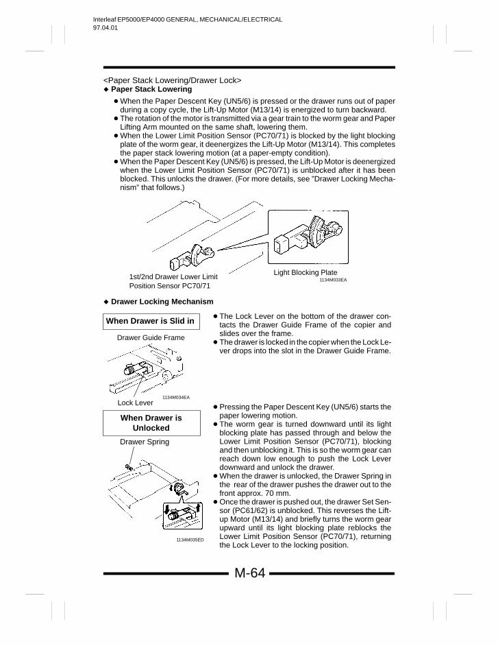
Interleaf EP5000/EP4000 GENERAL, MECHANICAL/ELECTRICAL97.04.01
M-64
<Paper Stack Lowering/Drawer Lock> Paper Stack Lowering
When the Paper Descent Key (UN5/6) is pressed or the drawer runs out of paperduring a copy cycle, the Lift-Up Motor (M13/14) is energized to turn backward.
The rotation of the motor is transmitted via a gear train to the worm gear and PaperLifting Arm mounted on the same shaft, lowering them.
When the Lower Limit Position Sensor (PC70/71) is blocked by the light blockingplate of the worm gear, it deenergizes the Lift-Up Motor (M13/14). This completesthe paper stack lowering motion (at a paper-empty condition).
When the Paper Descent Key (UN5/6) is pressed, the Lift-Up Motor is deenergizedwhen the Lower Limit Position Sensor (PC70/71) is unblocked after it has beenblocked. This unlocks the drawer. (For more details, see ”Drawer Locking Mecha-nism” that follows.)
1st/2nd Drawer Lower LimitPosition Sensor PC70/71
Light Blocking Plate1134M033EA
Drawer Locking Mechanism
Drawer Guide Frame
Lock Lever1134M034EA
Pressing the Paper Descent Key (UN5/6) starts thepaper lowering motion.
The worm gear is turned downward until its lightblocking plate has passed through and below theLower Limit Position Sensor (PC70/71), blockingand then unblocking it. This is so the worm gear canreach down low enough to push the Lock Leverdownward and unlock the drawer.
When the drawer is unlocked, the Drawer Spring inthe rear of the drawer pushes the drawer out to thefront approx. 70 mm.
Once the drawer is pushed out, the drawer Set Sen-sor (PC61/62) is unblocked. This reverses the Lift-up Motor (M13/14) and briefly turns the worm gearupward until its light blocking plate reblocks theLower Limit Position Sensor (PC70/71), returningthe Lock Lever to the locking position.
The Lock Lever on the bottom of the drawer con-tacts the Drawer Guide Frame of the copier andslides over the frame.
The drawer is locked in the copier when the Lock Le-ver drops into the slot in the Drawer Guide Frame.
1134M035ED
Drawer Spring
When Drawer is Slid in
When Drawer isUnlocked
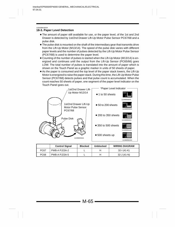
Interleaf EP5000/EP4000 GENERAL, MECHANICAL/ELECTRICAL97.04.01
M-65
1156SBM1803A
18-3. Paper Level Detection
The amount of paper still available for use, or the paper level, of the 1st and 2ndDrawer is detected by 1st/2nd Drawer Lift-Up Motor Pulse Sensor PC67/68 and apulse disk.
The pulse disk is mounted on the shaft of the intermediary gear that transmits drivefrom the Lift-Up Motor (M13/14). The speed of the pulse disk varies with differentpaper levels and the number of pulses detected by the Lift-Up Motor Pulse Sensor(PC67/68) is used to determine the paper level.
Counting of the number of pulses is started when the Lift-Up Motor (M13/14) is en-ergized and continues until the output from the Lift-Up Sensor (PC65/66) goesLOW. The total number of pulses is translated into the amount of paper which isshown on the Touch Panel as a graphic marker in units of 50 sheets of paper.
As the paper is consumed and the top level of the paper stack lowers, the Lift-UpMotor is energized to raise the paper stack. During this time, the Lift-Up Motor PulseSensor (PC67/68) detects pulses and that pulse count is accumulated. When thecount reaches 50 sheets of paper, one segment of the paper level indicator on theTouch Panel goes out.
1 to 50 sheets
50 to 200 sheets
200 to 350 sheets
350 to 500 sheets
500 sheets up
1134M058AA
1134M059AA
1134M060AA
1134M061AA
1134M062AA
*Paper Level Indicator1st/2nd Drawer Lift-Up Motor M13/14
1st/2nd Drawer Lift-UpMotor Pulse SensorPC67/68
Pulse Disk
1134M020AA
Control Signal Blocked Unblocked WIRING DIAGRAM
PC67 PWB-A PJ23A-2 L H 32-I (41-K)
PC68 PWB-A PJ23A-5 L H 32-J (41-N)
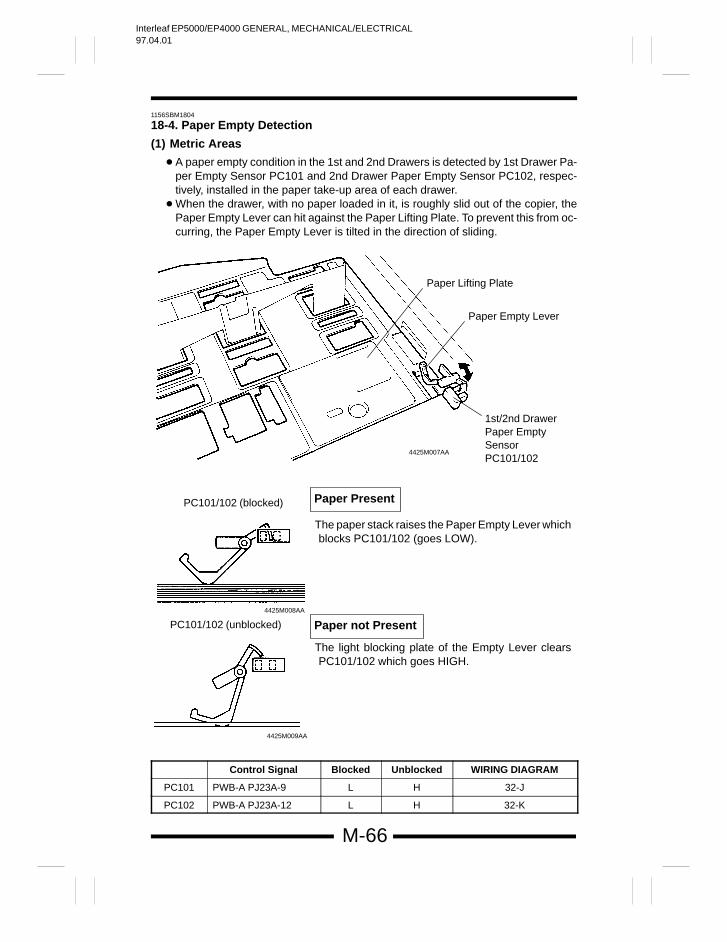
Interleaf EP5000/EP4000 GENERAL, MECHANICAL/ELECTRICAL97.04.01
M-66
1156SBM1804
18-4. Paper Empty Detection
(1) Metric Areas
A paper empty condition in the 1st and 2nd Drawers is detected by 1st Drawer Pa-per Empty Sensor PC101 and 2nd Drawer Paper Empty Sensor PC102, respec-tively, installed in the paper take-up area of each drawer.
When the drawer, with no paper loaded in it, is roughly slid out of the copier, thePaper Empty Lever can hit against the Paper Lifting Plate. To prevent this from oc-curring, the Paper Empty Lever is tilted in the direction of sliding.
Paper Lifting Plate
Paper Empty Lever
1st/2nd DrawerPaper EmptySensorPC101/102
4425M007AA
PC101/102 (blocked)
PC101/102 (unblocked)
4425M008AA
4425M009AA
The paper stack raises the Paper Empty Lever whichblocks PC101/102 (goes LOW).
The light blocking plate of the Empty Lever clearsPC101/102 which goes HIGH.
Paper Present
Paper not Present
Control Signal Blocked Unblocked WIRING DIAGRAM
PC101 PWB-A PJ23A-9 L H 32-J
PC102 PWB-A PJ23A-12 L H 32-K
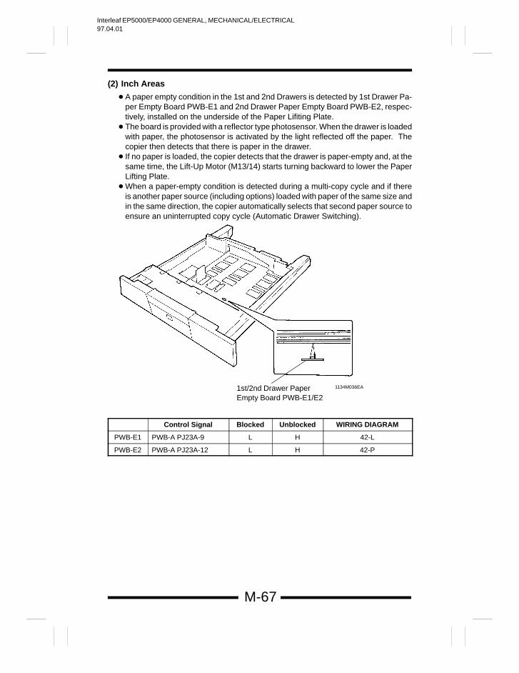
Interleaf EP5000/EP4000 GENERAL, MECHANICAL/ELECTRICAL97.04.01
M-67
(2) Inch Areas
A paper empty condition in the 1st and 2nd Drawers is detected by 1st Drawer Pa-per Empty Board PWB-E1 and 2nd Drawer Paper Empty Board PWB-E2, respec-tively, installed on the underside of the Paper Lifiting Plate.
The board is provided with a reflector type photosensor. When the drawer is loadedwith paper, the photosensor is activated by the light reflected off the paper. Thecopier then detects that there is paper in the drawer.
If no paper is loaded, the copier detects that the drawer is paper-empty and, at thesame time, the Lift-Up Motor (M13/14) starts turning backward to lower the PaperLifting Plate.
When a paper-empty condition is detected during a multi-copy cycle and if thereis another paper source (including options) loaded with paper of the same size andin the same direction, the copier automatically selects that second paper source toensure an uninterrupted copy cycle (Automatic Drawer Switching).
1st/2nd Drawer PaperEmpty Board PWB-E1/E2
1134M036EA
Control Signal Blocked Unblocked WIRING DIAGRAM
PWB-E1 PWB-A PJ23A-9 L H 42-L
PWB-E2 PWB-A PJ23A-12 L H 42-P
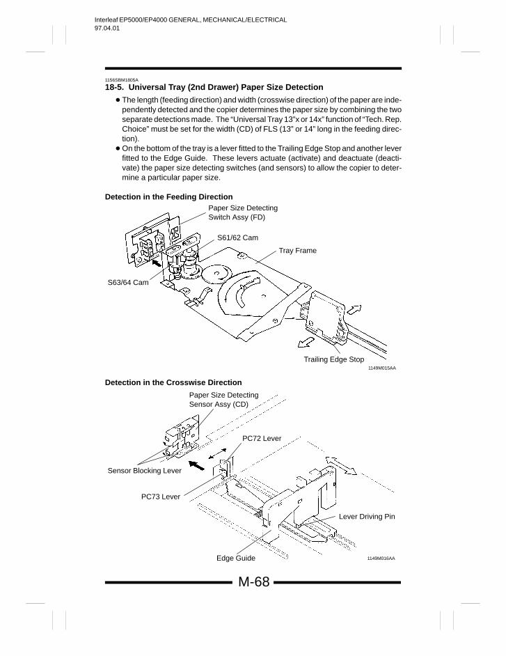
Interleaf EP5000/EP4000 GENERAL, MECHANICAL/ELECTRICAL97.04.01
M-68
1156SBM1805A
18-5. Universal Tray (2nd Drawer) Paper Size Detection
The length (feeding direction) and width (crosswise direction) of the paper are inde-pendently detected and the copier determines the paper size by combining the twoseparate detections made. The “Universal Tray 13”x or 14x” function of “Tech. Rep.Choice” must be set for the width (CD) of FLS (13” or 14” long in the feeding direc-tion).
On the bottom of the tray is a lever fitted to the Trailing Edge Stop and another leverfitted to the Edge Guide. These levers actuate (activate) and deactuate (deacti-vate) the paper size detecting switches (and sensors) to allow the copier to deter-mine a particular paper size.
Detection in the Feeding DirectionPaper Size Detecting Switch Assy (FD)
S61/62 Cam
Tray Frame
S63/64 Cam
Trailing Edge Stop1149M015AA
Detection in the Crosswise Direction
Sensor Blocking Lever
Paper Size Detecting Sensor Assy (CD)
PC73 Lever
PC72 Lever
Lever Driving Pin
1149M016AAEdge Guide
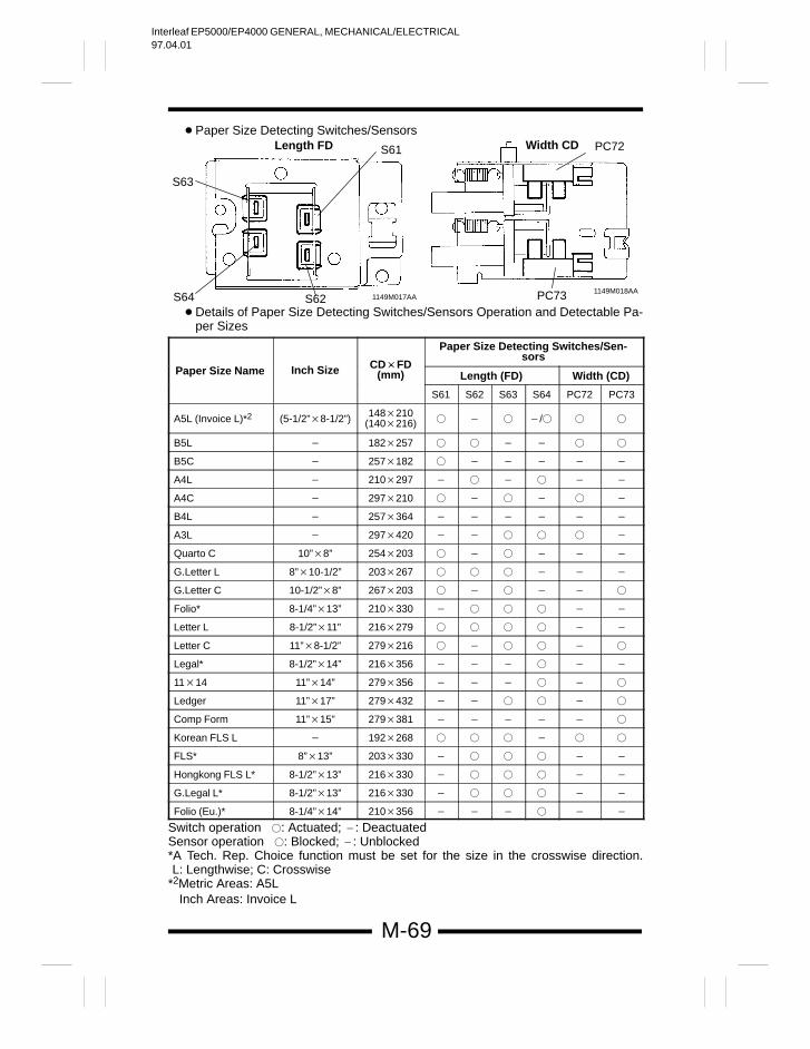
Interleaf EP5000/EP4000 GENERAL, MECHANICAL/ELECTRICAL97.04.01
M-69
Paper Size Detecting Switches/SensorsLength FD Width CD
PC73S62
PC72
S64
S63
S61
1149M017AA1149M018AA
Details of Paper Size Detecting Switches/Sensors Operation and Detectable Pa-per Sizes
Paper Size Detecting Switches/Sen-sors
Paper Size Name Inch Size CDFD(mm) Length (FD) Width (CD)
S61 S62 S63 S64 PC72 PC73
A5L (Invoice L)*2 (5-1/2”8-1/2”) 148210(140216) /
B5L 182257
B5C 257182
A4L 210297
A4C 297210
B4L 257364
A3L 297420
Quarto C 10”8” 254203
G.Letter L 8”10-1/2” 203267
G.Letter C 10-1/2”8” 267203
Folio* 8-1/4”13” 210330
Letter L 8-1/2”11” 216279
Letter C 11”8-1/2” 279216
Legal* 8-1/2”14” 216356
1114 11”14” 279356
Ledger 11”17” 279432
Comp Form 11”15” 279381
Korean FLS L 192268
FLS* 8”13” 203330
Hongkong FLS L* 8-1/2”13” 216330
G.Legal L* 8-1/2”13” 216330
Folio (Eu.)* 8-1/4”14” 210356
Switch operation : Actuated; : Deactuated Sensor operation : Blocked; : Unblocked*A Tech. Rep. Choice function must be set for the size in the crosswise direction.L: Lengthwise; C: Crosswise
*2Metric Areas: A5L Inch Areas: Invoice L
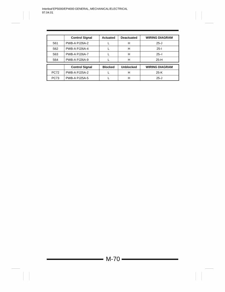
Interleaf EP5000/EP4000 GENERAL, MECHANICAL/ELECTRICAL97.04.01
M-70
Control Signal Actuated Deactuated WIRING DIAGRAM
S61 PWB-A PJ26A-2 L H 25-J
S62 PWB-A PJ26A-4 L H 25-I
S63 PWB-A PJ26A-7 L H 25–I
S64 PWB-A PJ26A-9 L H 25-H
Control Signal Blocked Unblocked WIRING DIAGRAM
PC72 PWB-A PJ25A-2 L H 25-K
PC73 PWB-A PJ25A-5 L H 25-J
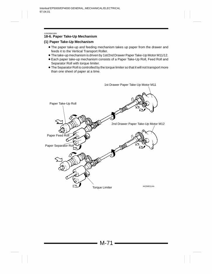
Interleaf EP5000/EP4000 GENERAL, MECHANICAL/ELECTRICAL97.04.01
M-71
1156SBM1806
18-6. Paper Take-Up Mechanism
(1) Paper Take-Up Mechanism
The paper take-up and feeding mechanism takes up paper from the drawer andfeeds it to the Vertical Transport Roller.
The take-up mechanism is driven by 1st/2nd Drawer Paper Take-Up Motor M11/12. Each paper take-up mechanism consists of a Paper Take-Up Roll, Feed Roll and
Separator Roll with torque limiter. The Separator Roll is controlled by the torque limiter so that it will not transport more
than one sheet of paper at a time.
Paper Feed Roll
Paper Separator Roll
Paper Take-Up Roll
Torque Limiter
2nd Drawer Paper Take-Up Motor M12
1st Drawer Paper Take-Up Motor M11
4425M011AA
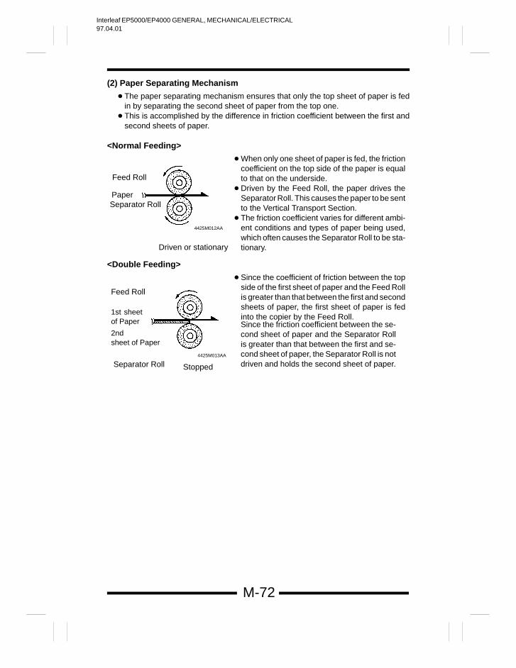
Interleaf EP5000/EP4000 GENERAL, MECHANICAL/ELECTRICAL97.04.01
M-72
(2) Paper Separating Mechanism
The paper separating mechanism ensures that only the top sheet of paper is fedin by separating the second sheet of paper from the top one.
This is accomplished by the difference in friction coefficient between the first andsecond sheets of paper.
<Normal Feeding>
When only one sheet of paper is fed, the frictioncoefficient on the top side of the paper is equalto that on the underside.
Driven by the Feed Roll, the paper drives theSeparator Roll. This causes the paper to be sentto the Vertical Transport Section.
The friction coefficient varies for different ambi-ent conditions and types of paper being used,which often causes the Separator Roll to be sta-tionary.
Paper
Feed Roll
Separator Roll
4425M012AA
Driven or stationary
<Double Feeding>
Since the coefficient of friction between the topside of the first sheet of paper and the Feed Rollis greater than that between the first and secondsheets of paper, the first sheet of paper is fedinto the copier by the Feed Roll.
Feed Roll
1st sheetof Paper
2nd sheet of Paper
4425M013AA
Since the friction coefficient between the se-cond sheet of paper and the Separator Rollis greater than that between the first and se-cond sheet of paper, the Separator Roll is notdriven and holds the second sheet of paper.Separator Roll Stopped
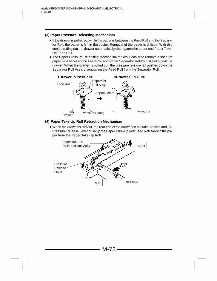
Interleaf EP5000/EP4000 GENERAL, MECHANICAL/ELECTRICAL97.04.01
M-73
(3) Paper Pressure Releasing Mechanism
If the drawer is pulled out while the paper is between the Feed Roll and the Separa-tor Roll, the paper is left in the copier. Removal of the paper is difficult. With thiscopier, sliding out the drawer automatically disengages the paper and Paper Take-Up/Feed Roll.
The Paper Pressure Releasing Mechanism makes it easier to remove a sheet ofpaper held between the Feed Roll and Paper Separator Roll by just sliding out thedrawer. When the drawer is pulled out, the pressure release rail pushes down theSeparator Roll Assy, disengaging the Feed Roll from the Separator Roll.
<Drawer in Position> <Drawer Slid Out>
Feed RollSeparatorRoll Assy
DrawerPressure Spring
Approx. 2mm
4444M004AA
(4) Paper Take-Up Roll Retraction Mechanism
When the drawer is slid out, the rear end of the drawer on the take-up side and thePressure Release Lever push up the Paper Take-Up Roll/Feed Roll, freeing the pa-per from the Paper Take-Up Roll.
PressureReleaseLever
Paper Take-UpRoll/Feed Roll Assy
1134M021AA
Front
Rear
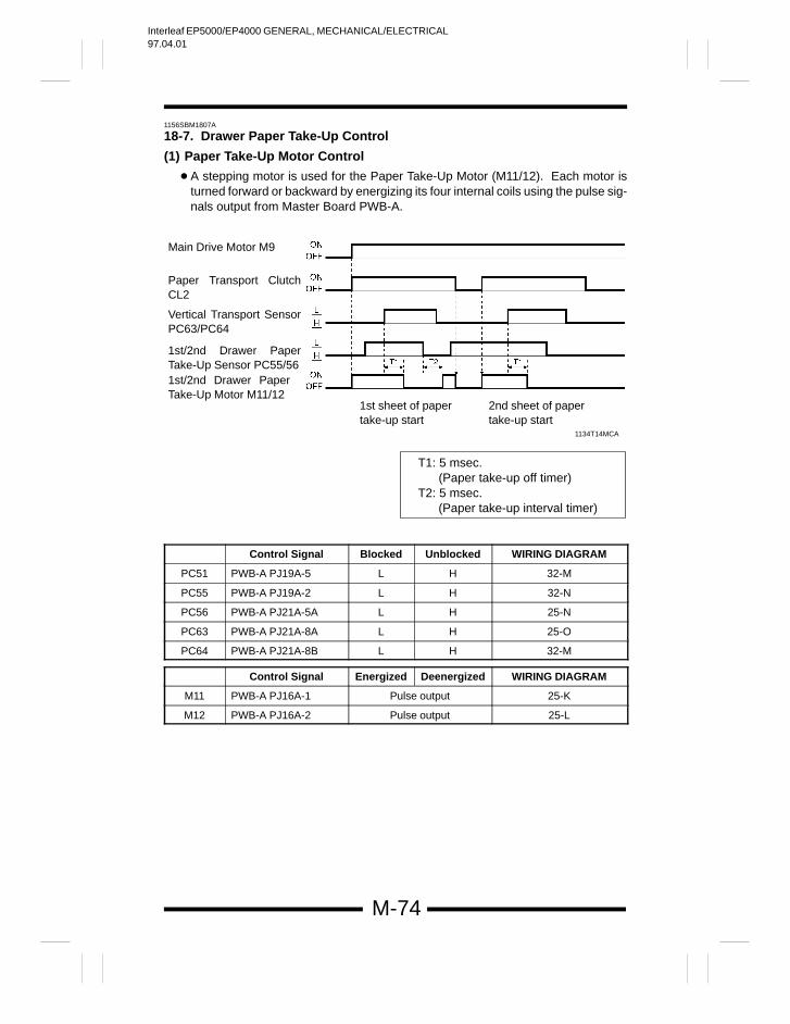
Interleaf EP5000/EP4000 GENERAL, MECHANICAL/ELECTRICAL97.04.01
M-74
1156SBM1807A
18-7. Drawer Paper Take-Up Control
(1) Paper Take-Up Motor Control
A stepping motor is used for the Paper Take-Up Motor (M11/12). Each motor isturned forward or backward by energizing its four internal coils using the pulse sig-nals output from Master Board PWB-A.
1134T14MCA
Main Drive Motor M9
Paper Transport ClutchCL2
1st/2nd Drawer PaperTake-Up Motor M11/12
1st/2nd Drawer PaperTake-Up Sensor PC55/56
Vertical Transport SensorPC63/PC64
1st sheet of papertake-up start
2nd sheet of papertake-up start
T1: 5 msec. (Paper take-up off timer)T2: 5 msec. (Paper take-up interval timer)
Control Signal Blocked Unblocked WIRING DIAGRAM
PC51 PWB-A PJ19A-5 L H 32-M
PC55 PWB-A PJ19A-2 L H 32-N
PC56 PWB-A PJ21A-5A L H 25-N
PC63 PWB-A PJ21A-8A L H 25-O
PC64 PWB-A PJ21A-8B L H 32-M
Control Signal Energized Deenergized WIRING DIAGRAM
M11 PWB-A PJ16A-1 Pulse output 25-K
M12 PWB-A PJ16A-2 Pulse output 25-L
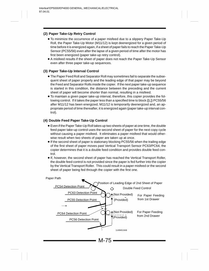
Interleaf EP5000/EP4000 GENERAL, MECHANICAL/ELECTRICAL97.04.01
M-75
(2) Paper Take-Up Retry Control
To minimize the occurrence of a paper misfeed due to a slippery Paper Take-UpRoll, the Paper Take-Up Motor (M11/12) is kept deenergized for a given period oftime before it is energized again, if a sheet of paper fails to reach the Paper Take-UpSensor (PC55/56) even after the lapse of a given period of time after the motor hasfirst been energized (paper take-up retry control).
A misfeed results if the sheet of paper does not reach the Paper Take-Up Sensoreven after three paper take-up sequences.
(3) Paper Take-Up Interval Control
The Paper Feed Roll and Separator Roll may sometimes fail to separate the subse-quent sheet of paper properly and the leading edge of that paper may be beyondthe Feed and Separator Rolls inside the copier. If the next paper take-up sequenceis started in this condition, the distance between the preceding and the currentsheet of paper will become shorter than normal, resulting in a misfeed.
To maintain a given paper take-up interval, therefore, this copier provides the fol-lowing control. If it takes the paper less than a specified time to block ([L]) PC55/56after M11/12 has been energized, M11/12 is temporarily deenergized and, an ap-propriate period of time thereafter, it is energized again (paper take-up interval con-trol).
(4) Double Feed Paper Take-Up Control
Even if the Paper Take-Up Roll takes up two sheets of paper at one time, the doublefeed paper take-up control uses the second sheet of paper for the next copy cyclewithout causing a paper misfeed. It eliminates a paper misfeed that would other-wise result when two sheets of paper are taken up at once.
If the second sheet of paper is stationary blocking PC55/56 when the trailing edgeof the first sheet of paper moves past Vertical Transport Sensor PC63/PC64, thecopier determines that it is a double feed condition and provides double feed con-trol.
If, however, the second sheet of paper has reached the Vertical Transport Roller,the double feed control is not provided since the paper is fed further into the copierby the Vertical Transport Roller. This could result in a paper misfeed or the secondsheet of paper being fed through the copier with the first one.
1149M019AB
Paper Path
PC56 Detection Point
PC64 Detection Point
PC55 Detection Point
PC54 Detection PointPosition of Leading Edge of 2nd Sheet of Paper
Double Feed Control
For Paper Feedingfrom 1st Drawer
(Not Provided)
(Provided)
For Paper Feedingfrom 2nd Drawer
(Not Provided)
(Provided)
PC63 Detection Point
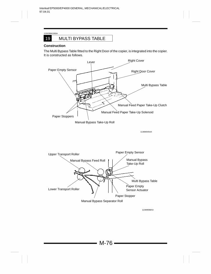
Interleaf EP5000/EP4000 GENERAL, MECHANICAL/ELECTRICAL97.04.01
M-76
1156SBM1900A
MULTI BYPASS TABLE19
Construction
The Multi Bypass Table fitted to the Right Door of the copier, is integrated into the copier.It is constructed as follows.
Paper Empty Sensor
1136M045AA
Lever Right Cover
Right Door Cover
Multi Bypass Table
Manual Feed Paper Take-Up Clutch
Manual Feed Paper Take-Up Solenoid
Manual Bypass Take-Up Roll
Paper Stoppers
Upper Transport Roller
Manual Bypass Feed Roll
Paper Empty Sensor
Manual BypassTake-Up Roll
Multi Bypass Table
Paper EmptySensor Actuator
Paper Stopper
Lower Transport Roller
Manual Bypass Separator Roll
1136M088AA
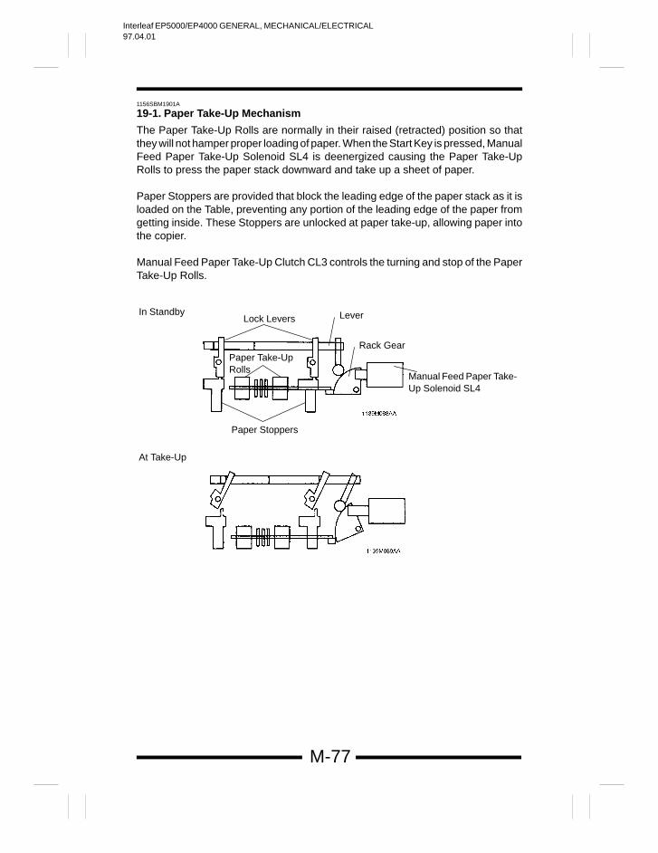
Interleaf EP5000/EP4000 GENERAL, MECHANICAL/ELECTRICAL97.04.01
M-77
1156SBM1901A
19-1. Paper Take-Up Mechanism
The Paper Take-Up Rolls are normally in their raised (retracted) position so thatthey will not hamper proper loading of paper. When the Start Key is pressed, ManualFeed Paper Take-Up Solenoid SL4 is deenergized causing the Paper Take-UpRolls to press the paper stack downward and take up a sheet of paper.
Paper Stoppers are provided that block the leading edge of the paper stack as it isloaded on the Table, preventing any portion of the leading edge of the paper fromgetting inside. These Stoppers are unlocked at paper take-up, allowing paper intothe copier.
Manual Feed Paper Take-Up Clutch CL3 controls the turning and stop of the PaperTake-Up Rolls.
Lock LeversIn Standby
At Take-Up
Lever
Rack Gear
Manual Feed Paper Take-Up Solenoid SL4
Paper Take-Up Rolls
Paper Stoppers
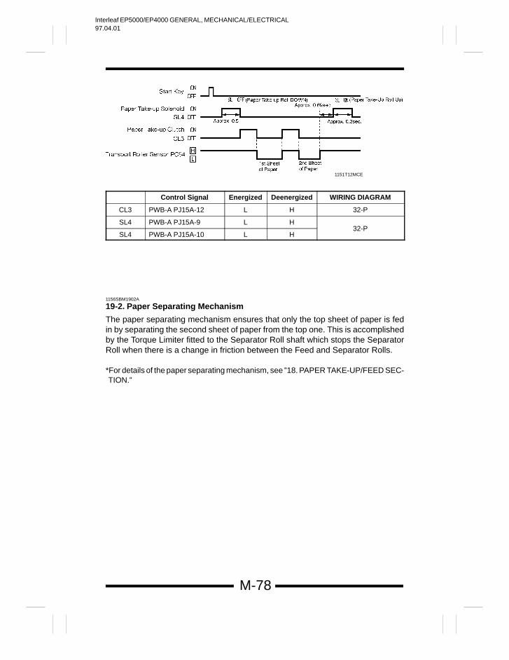
Interleaf EP5000/EP4000 GENERAL, MECHANICAL/ELECTRICAL97.04.01
M-78
1151T12MCE
Control Signal Energized Deenergized WIRING DIAGRAM
CL3 PWB-A PJ15A-12 L H 32-P
SL4 PWB-A PJ15A-9 L H
SL4 PWB-A PJ15A-10 L H32-P
1156SBM1902A
19-2. Paper Separating Mechanism
The paper separating mechanism ensures that only the top sheet of paper is fedin by separating the second sheet of paper from the top one. This is accomplishedby the Torque Limiter fitted to the Separator Roll shaft which stops the SeparatorRoll when there is a change in friction between the Feed and Separator Rolls.
*For details of the paper separating mechanism, see ”18. PAPER TAKE-UP/FEED SEC-TION.”
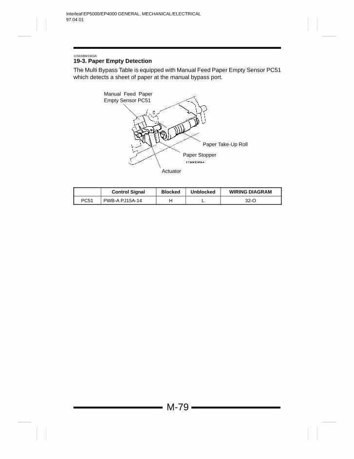
Interleaf EP5000/EP4000 GENERAL, MECHANICAL/ELECTRICAL97.04.01
M-79
1156SBM1903A
19-3. Paper Empty Detection
The Multi Bypass Table is equipped with Manual Feed Paper Empty Sensor PC51which detects a sheet of paper at the manual bypass port.
Manual Feed PaperEmpty Sensor PC51
Actuator
Paper Stopper
Paper Take-Up Roll
Control Signal Blocked Unblocked WIRING DIAGRAM
PC51 PWB-A PJ15A-14 H L 32-O
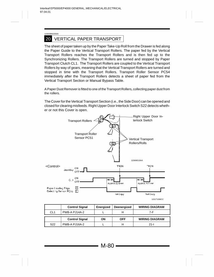
Interleaf EP5000/EP4000 GENERAL, MECHANICAL/ELECTRICAL97.04.01
M-80
1156SBM2000A
VERTICAL PAPER TRANSPORT20
The sheet of paper taken up by the Paper Take-Up Roll from the Drawer is fed alongthe Paper Guide to the Vertical Transport Rollers. The paper fed by the VerticalTransport Rollers reaches the Transport Rollers and is then fed up to theSynchronizing Rollers. The Transport Rollers are turned and stopped by PaperTransport Clutch CL1. The Transport Rollers are coupled to the Vertical TransportRollers by way of gears, meaning that the Vertical Transport Rollers are turned andstopped in time with the Transport Rollers. Transport Roller Sensor PC54immediately after the Transport Rollers detects a sheet of paper fed from theVertical Transport Section or Manual Bypass Table.
A Paper Dust Remover is fitted to one of the Transport Rollers, collecting paper dust fromthe rollers.
The Cover for the Vertical Transport Section (i.e., the Side Door) can be opened andclosed for clearing misfeeds. Right Upper Door Interlock Switch S22 detects wheth-er or not this Cover is open.
<Control>
Transport Rollers
Transport RollerSensor PC51
Right Upper Door In-terlock Switch
Vertical Transport Rollers/Rolls
1151T10MCC
1156M019AA
Control Signal Energized Deenergized WIRING DIAGRAM
CL1 PWB-A PJ14A-2 L H 7-F
Control Signal ON OFF WIRING DIAGRAM
S22 PWB-A PJ16A-2 L H 21-I
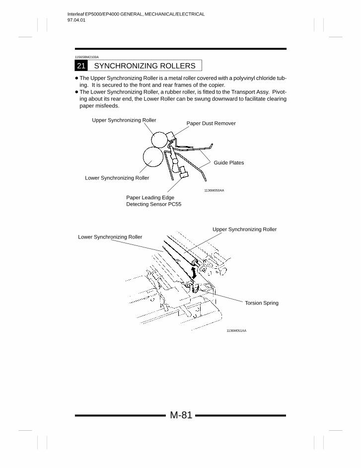
Interleaf EP5000/EP4000 GENERAL, MECHANICAL/ELECTRICAL97.04.01
M-81
1156SBM2100A
SYNCHRONIZING ROLLERS21
The Upper Synchronizing Roller is a metal roller covered with a polyvinyl chloride tub-ing. It is secured to the front and rear frames of the copier.
The Lower Synchronizing Roller, a rubber roller, is fitted to the Transport Assy. Pivot-ing about its rear end, the Lower Roller can be swung downward to facilitate clearingpaper misfeeds.
Upper Synchronizing Roller
Lower Synchronizing Roller
1136M050AA
Paper Dust Remover
Guide Plates
Lower Synchronizing Roller
Paper Leading Edge Detecting Sensor PC55
Upper Synchronizing Roller
Torsion Spring
1136M051AA
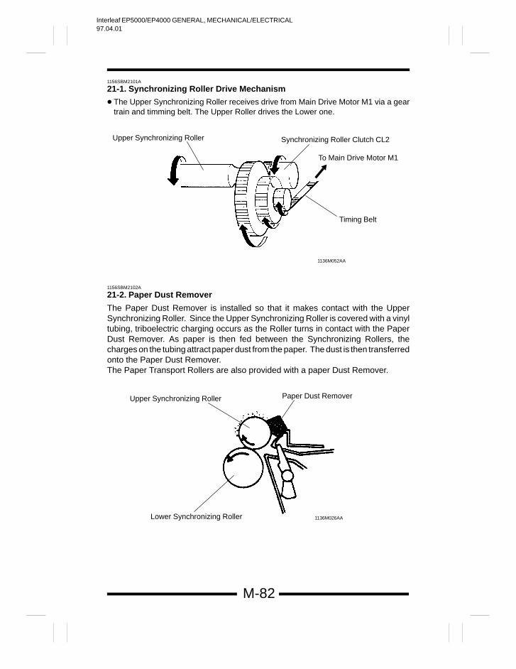
Interleaf EP5000/EP4000 GENERAL, MECHANICAL/ELECTRICAL97.04.01
M-82
1156SBM2101A
21-1. Synchronizing Roller Drive Mechanism
The Upper Synchronizing Roller receives drive from Main Drive Motor M1 via a geartrain and timming belt. The Upper Roller drives the Lower one.
Upper Synchronizing Roller Synchronizing Roller Clutch CL2
To Main Drive Motor M1
Timing Belt
1136M052AA
1156SBM2102A
21-2. Paper Dust Remover
The Paper Dust Remover is installed so that it makes contact with the UpperSynchronizing Roller. Since the Upper Synchronizing Roller is covered with a vinyltubing, triboelectric charging occurs as the Roller turns in contact with the PaperDust Remover. As paper is then fed between the Synchronizing Rollers, thecharges on the tubing attract paper dust from the paper. The dust is then transferredonto the Paper Dust Remover.The Paper Transport Rollers are also provided with a paper Dust Remover.
Upper Synchronizing Roller
1136M026AA
Paper Dust Remover
Lower Synchronizing Roller
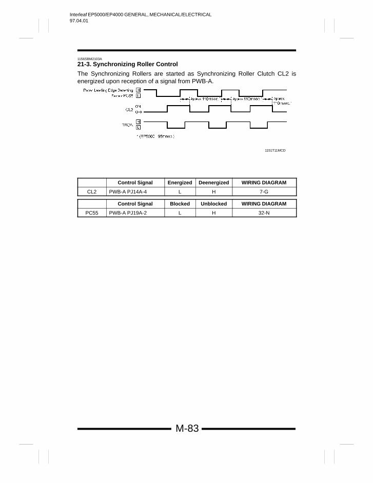
Interleaf EP5000/EP4000 GENERAL, MECHANICAL/ELECTRICAL97.04.01
M-83
1156SBM2103A
21-3. Synchronizing Roller Control
The Synchronizing Rollers are started as Synchronizing Roller Clutch CL2 isenergized upon reception of a signal from PWB-A.
1151T11MCD
Control Signal Energized Deenergized WIRING DIAGRAM
CL2 PWB-A PJ14A-4 L H 7-G
Control Signal Blocked Unblocked WIRING DIAGRAM
PC55 PWB-A PJ19A-2 L H 32-N
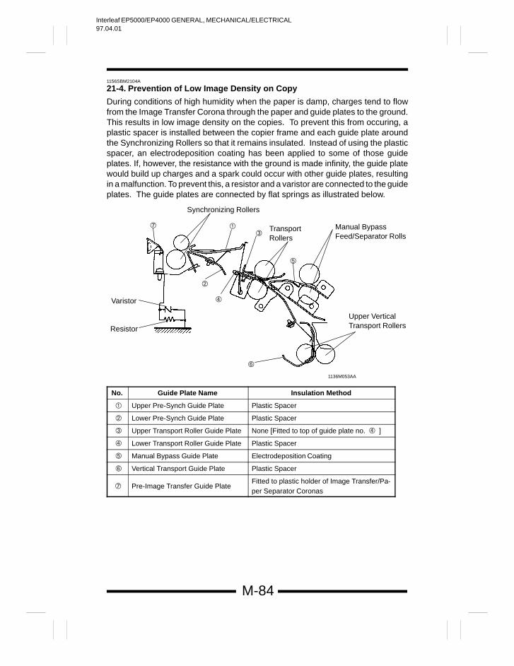
Interleaf EP5000/EP4000 GENERAL, MECHANICAL/ELECTRICAL97.04.01
M-84
1156SBM2104A
21-4. Prevention of Low Image Density on Copy
During conditions of high humidity when the paper is damp, charges tend to flowfrom the Image Transfer Corona through the paper and guide plates to the ground.This results in low image density on the copies. To prevent this from occuring, aplastic spacer is installed between the copier frame and each guide plate aroundthe Synchronizing Rollers so that it remains insulated. Instead of using the plasticspacer, an electrodeposition coating has been applied to some of those guideplates. If, however, the resistance with the ground is made infinity, the guide platewould build up charges and a spark could occur with other guide plates, resultingin a malfunction. To prevent this, a resistor and a varistor are connected to the guideplates. The guide plates are connected by flat springs as illustrated below.
Upper VerticalTransport Rollers
1136M053AA
Varistor
Resistor
Manual BypassFeed/Separator Rolls
Transport Rollers
Synchronizing Rollers
No. Guide Plate Name Insulation Method
Upper Pre-Synch Guide Plate Plastic Spacer
Lower Pre-Synch Guide Plate Plastic Spacer
Upper Transport Roller Guide Plate None [Fitted to top of guide plate no. ]
Lower Transport Roller Guide Plate Plastic Spacer
Manual Bypass Guide Plate Electrodeposition Coating
Vertical Transport Guide Plate Plastic Spacer
Pre-Image Transfer Guide PlateFitted to plastic holder of Image Transfer/Pa-per Separator Coronas
Interleaf EP5000/EP4000 GENERAL, MECHANICAL/ELECTRICAL97.04.01
M-85
Flat Spring Connection
A Between varistor-and-resistor and guide plate
B Between varistor-and-resistor and guide plate
C Between guide plates and
D Between guide plates and
E Between guide plates and
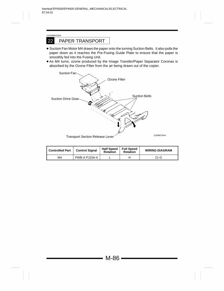
Interleaf EP5000/EP4000 GENERAL, MECHANICAL/ELECTRICAL97.04.01
M-86
1156SBM2200A
PAPER TRANSPORT22
Suction Fan Motor M4 draws the paper onto the turning Suction Belts. It also pulls thepaper down as it reaches the Pre-Fusing Guide Plate to ensure that the paper issmoothly fed into the Fusing Unit.
As M4 turns, ozone produced by the Image Transfer/Paper Separator Coronas isabsorbed by the Ozone Filter from the air being drawn out of the copier.
Ozone Filter
1136M070AA
Suction Belts
Transport Section Release Lever
Suction Drive Gear
Suction Fan
Controlled Part Control Signal Half SpeedRotation
Full SpeedRotation WIRING DIAGRAM
M4 PWB-A PJ15A-4 L H 21-G
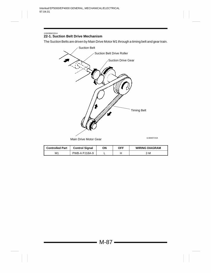
Interleaf EP5000/EP4000 GENERAL, MECHANICAL/ELECTRICAL97.04.01
M-87
1156SBM2201A
22-1. Suction Belt Drive Mechanism
The Suction Belts are driven by Main Drive Motor M1 through a timing belt and gear train.
Suction Belt Drive Roller
1136M072AAMain Drive Motor Gear
Suction Belt
Suction Drive Gear
Timing Belt
Controlled Part Control Signal ON OFF WIRING DIAGRAM
M1 PWB-A PJ18A-9 L H 2-M
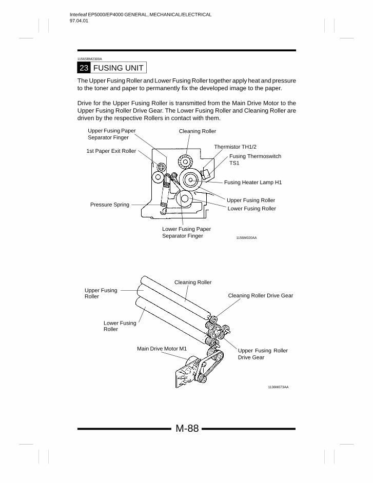
Interleaf EP5000/EP4000 GENERAL, MECHANICAL/ELECTRICAL97.04.01
M-88
1156SBM2300A
FUSING UNIT23
The Upper Fusing Roller and Lower Fusing Roller together apply heat and pressureto the toner and paper to permanently fix the developed image to the paper.
Drive for the Upper Fusing Roller is transmitted from the Main Drive Motor to theUpper Fusing Roller Drive Gear. The Lower Fusing Roller and Cleaning Roller aredriven by the respective Rollers in contact with them.
Pressure Spring
Thermistor TH1/2
Fusing Heater Lamp H1
Upper Fusing Roller
Lower Fusing Roller
Fusing ThermoswitchTS1
Lower Fusing PaperSeparator Finger 1156M020AA
1136M073AA
Cleaning Roller
1st Paper Exit Roller
Upper Fusing PaperSeparator Finger
Cleaning Roller
Cleaning Roller Drive Gear
Upper Fusing RollerDrive Gear
Upper FusingRoller
Lower FusingRoller
Main Drive Motor M1
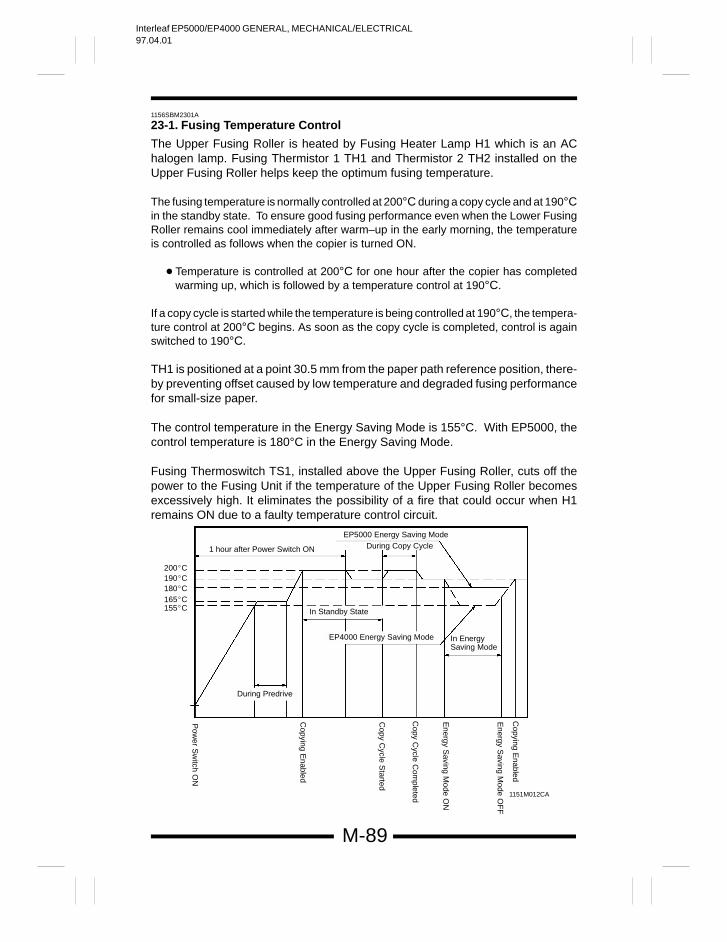
Interleaf EP5000/EP4000 GENERAL, MECHANICAL/ELECTRICAL97.04.01
M-89
1156SBM2301A
23-1. Fusing Temperature Control
The Upper Fusing Roller is heated by Fusing Heater Lamp H1 which is an AChalogen lamp. Fusing Thermistor 1 TH1 and Thermistor 2 TH2 installed on theUpper Fusing Roller helps keep the optimum fusing temperature.
The fusing temperature is normally controlled at 200°C during a copy cycle and at 190°Cin the standby state. To ensure good fusing performance even when the Lower FusingRoller remains cool immediately after warm–up in the early morning, the temperatureis controlled as follows when the copier is turned ON.
Temperature is controlled at 200°C for one hour after the copier has completedwarming up, which is followed by a temperature control at 190°C.
If a copy cycle is started while the temperature is being controlled at 190°C, the tempera-ture control at 200°C begins. As soon as the copy cycle is completed, control is againswitched to 190°C.
TH1 is positioned at a point 30.5 mm from the paper path reference position, there-by preventing offset caused by low temperature and degraded fusing performancefor small-size paper.
The control temperature in the Energy Saving Mode is 155°C. With EP5000, thecontrol temperature is 180°C in the Energy Saving Mode.
Fusing Thermoswitch TS1, installed above the Upper Fusing Roller, cuts off thepower to the Fusing Unit if the temperature of the Upper Fusing Roller becomesexcessively high. It eliminates the possibility of a fire that could occur when H1remains ON due to a faulty temperature control circuit.
1151M012CA
1 hour after Power Switch ON
EP5000 Energy Saving ModeDuring Copy Cycle
In Standby State
Copying E
nabled
Energy S
aving Mode O
FF
In EnergySaving Mode
Energy S
aving Mode O
N
Copy C
ycle Started
Copying E
nabled
During Predrive
Pow
er Sw
itch ON
Copy C
ycle Com
pleted
EP4000 Energy Saving Mode
200C190C180C165C155C
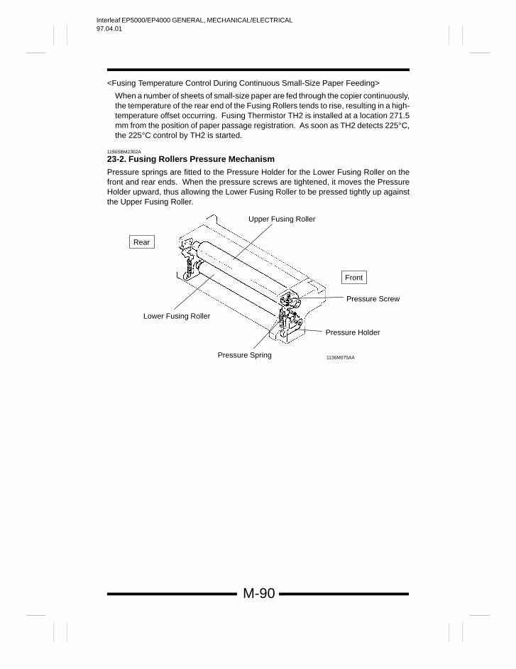
Interleaf EP5000/EP4000 GENERAL, MECHANICAL/ELECTRICAL97.04.01
M-90
<Fusing Temperature Control During Continuous Small-Size Paper Feeding>
When a number of sheets of small-size paper are fed through the copier continuously,the temperature of the rear end of the Fusing Rollers tends to rise, resulting in a high-temperature offset occurring. Fusing Thermistor TH2 is installed at a location 271.5mm from the position of paper passage registration. As soon as TH2 detects 225°C,the 225°C control by TH2 is started.
1156SBM2302A
23-2. Fusing Rollers Pressure Mechanism
Pressure springs are fitted to the Pressure Holder for the Lower Fusing Roller on thefront and rear ends. When the pressure screws are tightened, it moves the PressureHolder upward, thus allowing the Lower Fusing Roller to be pressed tightly up againstthe Upper Fusing Roller.
Upper Fusing Roller
Pressure Screw
Pressure Holder
Pressure Spring
Lower Fusing Roller
1136M075AA
Rear
Front
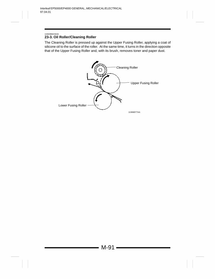
Interleaf EP5000/EP4000 GENERAL, MECHANICAL/ELECTRICAL97.04.01
M-91
1156SBM2303A
23-3. Oil Roller/Cleaning Roller
The Cleaning Roller is pressed up against the Upper Fusing Roller, applying a coat ofsilicone oil to the surface of the roller. At the same time, it turns in the direction oppositethat of the Upper Fusing Roller and, with its brush, removes toner and paper dust.
1136M077AA
Cleaning Roller
Upper Fusing Roller
Lower Fusing Roller
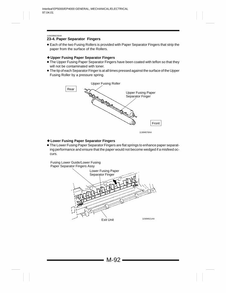
Interleaf EP5000/EP4000 GENERAL, MECHANICAL/ELECTRICAL97.04.01
M-92
1156SBM2304A
23-4. Paper Separator Fingers
Each of the two Fusing Rollers is provided with Paper Separator Fingers that strip thepaper from the surface of the Rollers.
Upper Fusing Paper Separator Fingers The Upper Fusing Paper Separator Fingers have been coated with teflon so that they
will not be contaminated with toner. The tip of each Separator Finger is at all times pressed against the surface of the Upper
Fusing Roller by a pressure spring.
1136M078AA
Upper Fusing Roller
Upper Fusing PaperSeparator Finger
Rear
Front
Lower Fusing Paper Separator Fingers The Lower Fusing Paper Separator Fingers are flat springs to enhance paper separat-
ing performance and ensure that the paper would not become wedged if a misfeed oc-curs.
Lower Fusing PaperSeparator Finger
Fusing Lower Guide/Lower FusingPaper Separator Fingers Assy
Exit Unit 1156M021AA
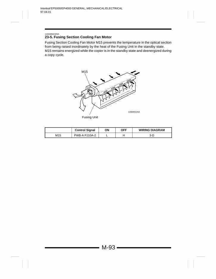
Interleaf EP5000/EP4000 GENERAL, MECHANICAL/ELECTRICAL97.04.01
M-93
1156SBM2305A
23-5. Fusing Section Cooling Fan Motor
Fusing Section Cooling Fan Motor M15 prevents the temperature in the optical sectionfrom being raised inordinately by the heat of the Fusing Unit in the standby state.M15 remains energized while the copier is in the standby state and deenergized duringa copy cycle.
M15
Fusing Unit
1156M022AA
Control Signal ON OFF WIRING DIAGRAM
M15 PWB-A PJ10A-2 L H 3-D
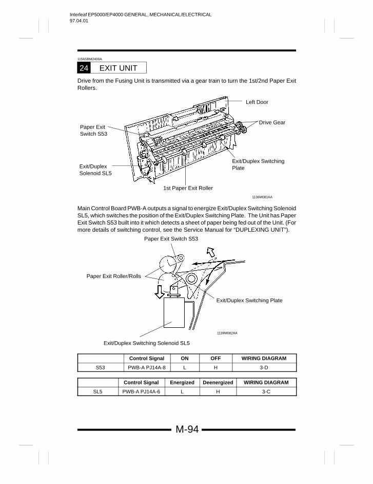
Interleaf EP5000/EP4000 GENERAL, MECHANICAL/ELECTRICAL97.04.01
M-94
1156SBM2400A
EXIT UNIT24
Drive from the Fusing Unit is transmitted via a gear train to turn the 1st/2nd Paper ExitRollers.
Left Door
1136M081AA
1st Paper Exit Roller
Drive Gear
Exit/Duplex SwitchingPlateExit/Duplex
Solenoid SL5
Paper ExitSwitch S53
Main Control Board PWB-A outputs a signal to energize Exit/Duplex Switching SolenoidSL5, which switches the position of the Exit/Duplex Switching Plate. The Unit has PaperExit Switch S53 built into it which detects a sheet of paper being fed out of the Unit. (Formore details of switching control, see the Service Manual for “DUPLEXING UNIT”).
1139M082AA
Exit/Duplex Switching Plate
Exit/Duplex Switching Solenoid SL5
Paper Exit Roller/Rolls
Paper Exit Switch S53
Control Signal ON OFF WIRING DIAGRAM
S53 PWB-A PJ14A-8 L H 3-D
Control Signal Energized Deenergized WIRING DIAGRAM
SL5 PWB-A PJ14A-6 L H 3-C
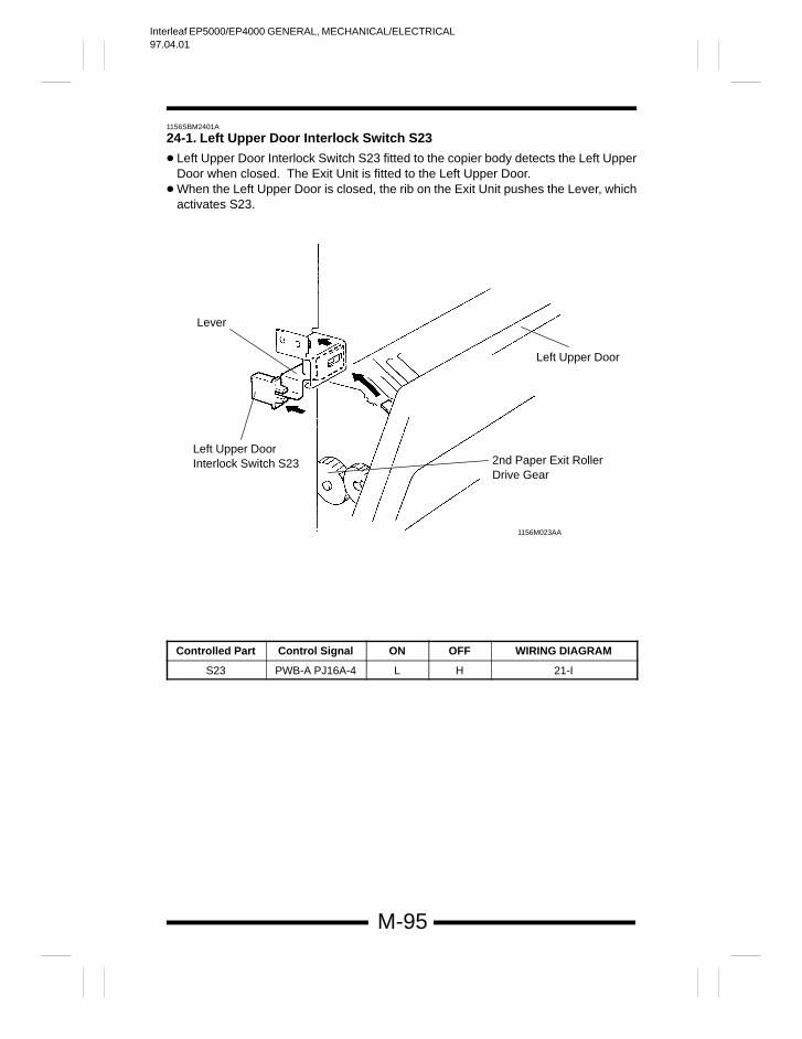
Interleaf EP5000/EP4000 GENERAL, MECHANICAL/ELECTRICAL97.04.01
M-95
1156SBM2401A
24-1. Left Upper Door Interlock Switch S23
Left Upper Door Interlock Switch S23 fitted to the copier body detects the Left UpperDoor when closed. The Exit Unit is fitted to the Left Upper Door.
When the Left Upper Door is closed, the rib on the Exit Unit pushes the Lever, whichactivates S23.
Left Upper Door
2nd Paper Exit Roller Drive Gear
Left Upper DoorInterlock Switch S23
Lever
1156M023AA
Controlled Part Control Signal ON OFF WIRING DIAGRAM
S23 PWB-A PJ16A-4 L H 21-I
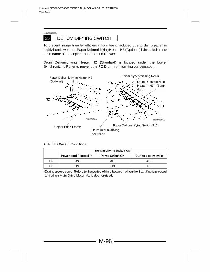
Interleaf EP5000/EP4000 GENERAL, MECHANICAL/ELECTRICAL97.04.01
M-96
1156SBM2500A
DEHUMIDIFYING SWITCH25
To prevent image transfer efficiency from being reduced due to damp paper inhighly humid weather, Paper Dehumidifying Heater H3 (Optional) is installed on thebase frame of the copier under the 2nd Drawer.
Drum Dehumidifying Heater H2 (Standard) is located under the LowerSynchronizing Roller to prevent the PC Drum from forming condensation.
Copier Base FrameDrum DehumidifyingSwitch S3
Lower Synchronizing RollerPaper Dehumidifying Heater H2(Optional)
Paper Dehumidifying Switch S12
1136M004AA1136M043AA
Drum DehumidifyingHeater H3 (Stan-dard)
H2, H3 ON/OFF Conditions
Dehumidifying Switch ON
Power cord Plugged in Power Switch ON *During a copy cycle
H2 ON OFF OFF
H3 ON ON OFF
*During a copy cycle: Refers to the period of time between when the Start Key is pressedand when Main Drive Motor M1 is deenergized.
Interleaf EP5000/EP4000 GENERAL, MECHANICAL/ELECTRICAL97.04.01
M-97
1156SBM2600A
MEMORY BACKUP26
IC1 (RAM) of RAM Board PWB-R connected to Main Control Board PWB-A storesthe setting/adjustment values set in the Tech. Rep. Modes as well as the countercounts. Backup Battery BAT1 is mounted on PWB-R to prevent the contents ofmemory from being lost when the power cord is unplugged or PWB-R removed fromthe copier. BAT1 requires a voltage of 2V or more to retain the contents of memory.
ImportantAs we noted above, the RAM stores critical data. If PWB-R has been replaced witha new one, memory must first be cleared and then all settings be made again. Itshould also be noted that PWB-R should not be replaced at the same time whenPWB-A is replaced.

Interleaf EP5000/EP4000 GENERAL, MECHANICAL/ELECTRICAL97.04.01
Copyright1997 MINOLTA Co., Ltd.
Printed in Japan
Use of this manual shouldbe strictly supervised to avoid disclosure of confidential information.
1156-7991-11 97046000
1156SBG000E
Interleaf EP5000/EP4000 DIS/REASSEMBLY, ADJUSTMENT97.04.01
1156SBD000AA
Interleaf EP5000/EP4000 DIS/REASSEMBLY, ADJUSTMENT97.04.01
i
1151SBD0000A
For the Utmost safety
For replacement parts, use the genuine parts with their part numbers specified in the parts manual. Use
of a wrong part could cause an overload or dielectric breakdown resulting in an electric shock or fire.
Replace a blown fuse or thermal fuse with the corresponding genuine part with its part number specified
in the parts manual. Use of a fuse with a different rating or one with the same rating but of a different
type can result in a fire.
Especially when a thermal fuse blows frequently, the thermal control system is probably faulty.
Be sure to take necessary action.
Before attempting to disassemble the machine, be sure to unplug its power cord. The machine contains
a high voltage unit and a circuit with a large current capacity that may cause an electric shock or burn
from sparking.
The machine also contains quick moving parts, which could injure a person.
If the machine uses a laser, a person can lose his/her eyesight by a laser beam leak.
Wherever feasible, keep the covers and parts mounted when energizing the machine.
If it is absolutely necessary to energize the machine with its cover removed, do not touch an exposed
part that is being charged and use care not to allow your clothing to be caught by a timing belt, gear,
or other moving part.
Do not leave the machine unattended while it is being energized.
Warning!
To actuate an interlock switch with a cover removed or opened, be sure to use the interlock switch actu-
ating jig. Use of folded paper can damage the interlock switch mechanism.
Caution!
Interleaf EP5000/EP4000 DIS/REASSEMBLY, ADJUSTMENT97.04.01
ii
A high voltage is being applied to the part marked with the symbol shown
on the right. Touching it can cause an electric shock. Be sure to unplug the
power cord when servicing this part or other parts near it.
When the machine is energized with any of its covers removed, never use a flammable spray near it,
as a fire can result.
Make sure that correct screws (diameter and length of the screw, binding/tapping screws) are used in
the correct places when assembling parts. If a wrong screw is used, a short insulating distance could
result. It could also result in collapsed threads, which provides only a poor grounding connection, result-
ing in an electric shock.
A toothed washer and spring washer, if used originally, must be reinstalled. If they are left out, a contact
failure results, causing an electric shock or fire.
Replace a lithium cell only with one having the part number specified in the parts manual. An explosion
could result if the cell is installed with wrong polarity or a wrong cell is installed.
Dispose of a used lithium cell according to the applicable local regulations. Never throw it away or aban-
don it on the user’s premises.
Caution!
Other Precautions While the machine is being energized, do not unplug or plug in a connector on a PWB or relay harness.
Since the Magnet Roller of the Imaging Unit generates a strong magnetic force, do not bring a CRT, watch,
floppy disk, or magnetic card near it.
Use of an air gun or vacuum generates static electricity which can cause the ATDC Sensor and associated
parts to break down. Be sure therefore to use a blower brush or cloth to clean these parts. If a unit is to
be cleaned, be sure to remove the sensors in advance.
MOS lCs are susceptible to static electricity. When handling a PWB loaded with MOS ICs, follow precau-
tions given in “INSTRUCTIONS FOR HANDLING THE PWBs WITH MOS ICs.”
The PC Drum is highly delicate. When handling the PC Drum, follow the precautions given in “HANDLING
OF THE PC DRUM.”
To reassemble, reverse the order of disassembly unless otherwise specified.
Note that replacement of a PWB may call for readjustments or resetting of particular items.
CAUTION: DANGER OF EXPLOSION IF BATTERY IS INCORRECTLY REPLACED. REPLACE
ONLY WITH THE SAME OR EQUIVALENT TYPE RECOMMENDED BY THE MANUFACTURER.
DISPOSE OF USED BATTERIES ACCORDING TO THE MANUFACTURER’S INSTRUCTIONS.
ADVARSEL!:Lithiumbatteri - Eksplosionsfare ved fejlagtig håndtering. Udskiftning må kun ske med
batteri af samme fabrikat og type. Levér det brugle bafferi tilbage til leverandoren.
Interleaf EP5000/EP4000 DIS/REASSEMBLY, ADJUSTMENT97.04.01
iii
1156SBD000BA
CONTENTS
SERVICE INSTRUCTIONS1
1-1. PRECAUTIONS FOR DISASSEMBLY/ADJUSTMENTS D-1. . . . . . 1-2. INSTRUCTIONS FOR HANDLING THE PWBs
WITH MOS ICs D-3. . . . . . . . . . . . . . . . . . . . . . . . . . . . . . . . . . . . . . . . . 1-3. HANDLING OF THE PC DRUM D-3. . . . . . . . . . . . . . . . . . . . . . . . . . 1-4. PARTS WHICH MUST NOT BE TOUCHED D-5. . . . . . . . . . . . . . . .
DISASSEMBLY/REASSEMBLY2
2-1. DOORS, COVERS, AND EXTERIOR PARTS:IDENTIFICATION AND REMOVAL PROCEDURES D-6. . . . . . . . .
2-2. REMOVAL OF CIRCUIT BOARDS D-8. . . . . . . . . . . . . . . . . . . . . . . . 2-3. PAPER TAKE-UP/TRANSPORT SECTIONS D-10. . . . . . . . . . . . . . .
(1) Removal of the Paper Take-Up Unit D-10. . . . . . . . . . . . . . . . . . . . . (2) Removal of the Paper Take-Up Roll/Feed Roll Assy and
Separator Roll Assy D-13. . . . . . . . . . . . . . . . . . . . . . . . . . . . . . . . . . (3) Cleaning of the Paper Take-Up Roll, Feed Roll,
and Separator Roll D-16. . . . . . . . . . . . . . . . . . . . . . . . . . . . . . . . . . . (4) Cleaning of the Vertical Transport Rollers D-17. . . . . . . . . . . . . . . . (5) Removal of the Drawers D-17. . . . . . . . . . . . . . . . . . . . . . . . . . . . . . . (6) Removal of the Upper Synchronizing Roller D-19. . . . . . . . . . . . . . (7) Cleaning of the Upper and Lower Synchronizing
Rollers D-20. . . . . . . . . . . . . . . . . . . . . . . . . . . . . . . . . . . . . . . . . . . . . . (8) Replacement of the Paper Dust Remover D-20. . . . . . . . . . . . . . . . (9) Cleaning of the Paper Dust Remover D-21. . . . . . . . . . . . . . . . . . . (10) Removal of the Suction Unit D-22. . . . . . . . . . . . . . . . . . . . . . . . . . (11) Disassembly of the Suction Unit D-23. . . . . . . . . . . . . . . . . . . . . . . (12) Disassembly of the Multi Bypass Unit D-24. . . . . . . . . . . . . . . . . .
2-4. OPTICAL SECTION D-28. . . . . . . . . . . . . . . . . . . . . . . . . . . . . . . . . . . . (1) Cleaning of the Original Glass D-28. . . . . . . . . . . . . . . . . . . . . . . . . . (2) Cleaning of the Scanner Shaft D-28. . . . . . . . . . . . . . . . . . . . . . . . . (3) Cleaning of the Scanner Rail D-28. . . . . . . . . . . . . . . . . . . . . . . . . . . (4) Removal of the Scanner D-29. . . . . . . . . . . . . . . . . . . . . . . . . . . . . . . (5) Cleaning of the Exposure Lamp D-29. . . . . . . . . . . . . . . . . . . . . . . . (6) Removal of the Thermal Fuse D-30. . . . . . . . . . . . . . . . . . . . . . . . . . (7) Cleaning of the 1st, 2nd, and 3rd Mirrors D-30. . . . . . . . . . . . . . . . (8) Cleaning of the Lens and 4th and 5th Mirrors D-31. . . . . . . . . . . . . (9) Winding of the Lens Drive Cable D-32. . . . . . . . . . . . . . . . . . . . . . . (10) Removal of Scanner Motor M2 D-34. . . . . . . . . . . . . . . . . . . . . . . . (11) Removal of the Scanner Drive Cable D-35. . . . . . . . . . . . . . . . . . (12) Winding of the Scanner Drive Cable D-36. . . . . . . . . . . . . . . . . . . (13) Cleaning of the 6th Mirror Protective Filter D-37. . . . . . . . . . . . . . (14) Cleaning of the Cooling Fan Filter D-37. . . . . . . . . . . . . . . . . . . . .
Interleaf EP5000/EP4000 DIS/REASSEMBLY, ADJUSTMENT97.04.01
iv
CONTENTS2-5. IMAGING UNIT D-38. . . . . . . . . . . . . . . . . . . . . . . . . . . . . . . . . . . . . . . . .
(1) Removal of the Imaging Unit D-38. . . . . . . . . . . . . . . . . . . . . . . . . . . (2) Disassembly of the Imaging Unit D-38. . . . . . . . . . . . . . . . . . . . . . . (3) Replacement of the PC Drum D-42. . . . . . . . . . . . . . . . . . . . . . . . . . (4) Cleaning of the Developer Scattering Prevention Plate D-42. . . . (5) Cleaning of the Ds Positioning Collars D-42. . . . . . . . . . . . . . . . . . . (6) Cleaning of the Toner Antispill Trap D-42. . . . . . . . . . . . . . . . . . . . . (7) Cleaning of the Cleaning Blade D-42. . . . . . . . . . . . . . . . . . . . . . . . . (8) Replacement of the Cleaning Blade D-43. . . . . . . . . . . . . . . . . . . . . (9) Replacement of the Starter D-45. . . . . . . . . . . . . . . . . . . . . . . . . . . . (10) Cleaning of the AIDC Sensor Board D-46. . . . . . . . . . . . . . . . . . . (11) Cleaning of the PC Drum Paper Separator Fingers D-46. . . . . . (12) Replacement and Cleaning of the Toner Antispill Seal
and Cleaning of the Toner Antispill Plate D-46. . . . . . . . . . . . . . . . . (13) Removal of Main Erase Lamp LA3 D-47. . . . . . . . . . . . . . . . . . . . (14) Cleaning of the Main Erase Lamp Filter D-47. . . . . . . . . . . . . . . . (15) Cleaning of Image Erase Lamp LA2 D-47. . . . . . . . . . . . . . . . . . . (16) Replacement of Image Erase Lamp LA2 D-47. . . . . . . . . . . . . . . (17) Removal of the Ozone Filter
(PC Drum Charge Corona) D-48. . . . . . . . . . . . . . . . . . . . . . . . . . . (18) Removal of the Ozone Filter
(Image Transfer/Paper Separator Coronas) D-48. . . . . . . . . . . . . (19) Removal of the Toner Collecting Box D-48. . . . . . . . . . . . . . . . . . .
2-6. PC DRUM CHARGE CORONA AND IMAGE TRANSFER/PAPER SEPARATOR CORONAS D-49. . . . . .
(1) Removal of the PC Drum Charge Corona D-49. . . . . . . . . . . . . . . . (2) Cleaning of the PC Drum Charge Corona Housing D-49. . . . . . . . (3) Cleaning of the PC Drum Charge Corona Grid Mesh D-50. . . . . . (4) Cleaning of the Comb Electrode D-50. . . . . . . . . . . . . . . . . . . . . . . . (5) Removal of the Image Transfer/Paper Separator
Coronas D-50. . . . . . . . . . . . . . . . . . . . . . . . . . . . . . . . . . . . . . . . . . . . (6) Cleaning and Replacement of the Image Transfer
Corona Wire D-50. . . . . . . . . . . . . . . . . . . . . . . . . . . . . . . . . . . . . . . . . (7) Cleaning and Replacement of the Paper Separator
Corona Wire D-51. . . . . . . . . . . . . . . . . . . . . . . . . . . . . . . . . . . . . . . . . (8) Cleaning of the Image Transfer/Paper Separator
Coronas Housing D-51. . . . . . . . . . . . . . . . . . . . . . . . . . . . . . . . . . . . . (9) Cleaning of the Lower Pre-Image Transfer
Guide Plate D-52. . . . . . . . . . . . . . . . . . . . . . . . . . . . . . . . . . . . . . . . . . 2-7. FUSING UNIT D-53. . . . . . . . . . . . . . . . . . . . . . . . . . . . . . . . . . . . . . . . . .
(1) Removal of the Fusing Unit D-53. . . . . . . . . . . . . . . . . . . . . . . . . . . . (2) Disassembly of the Fusing Unit D-53. . . . . . . . . . . . . . . . . . . . . . . . . (3) Replacement and Cleaning of the Upper Fusing Paper
Separator Fingers D-58. . . . . . . . . . . . . . . . . . . . . . . . . . . . . . . . . . . . (4) Cleaning of the Lower Fusing Paper Separator Fingers D-58. . . . (5) Cleaning of the Fusing Unit Entrance Guide Plate D-58. . . . . . . . .
Interleaf EP5000/EP4000 DIS/REASSEMBLY, ADJUSTMENT97.04.01
v
CONTENTS(6) Cleaning of Fusing Front and Rear Thermistors TH1/2 D-58. . . . (7) Cleaning of Fusing Thermoswitch TS1 D-59. . . . . . . . . . . . . . . . . . (8) Replacement and Cleaning of the Cleaning Roller D-59. . . . . . . . (9) Replacement and Cleaning of the Upper Fusing
Roller D-59. . . . . . . . . . . . . . . . . . . . . . . . . . . . . . . . . . . . . . . . . . . . . . . (10) Replacement and Cleaning of the Lower Fusing
Roller D-60. . . . . . . . . . . . . . . . . . . . . . . . . . . . . . . . . . . . . . . . . . . . . 2-8. EXIT UNIT D-61. . . . . . . . . . . . . . . . . . . . . . . . . . . . . . . . . . . . . . . . . . . . .
(1) Removal of the Exit/Duplex Switching Unit D-61. . . . . . . . . . . . . . .
ADJUSTMENT3
3-1. JIGS AND TOOLS USED D-62. . . . . . . . . . . . . . . . . . . . . . . . . . . . . . . . 3-2. ADJUSTMENT REQUIREMENTS LIST D-63. . . . . . . . . . . . . . . . . . . . 3-3. ADJUSTMENT OF SWITCHES D-64. . . . . . . . . . . . . . . . . . . . . . . . . . .
Adjustment of Front Door Interlock Switch S21 D-65. . . . . . . . . . . . . . 3-4. ADJUSTMENT OF BELT TENSION D-66. . . . . . . . . . . . . . . . . . . . . . .
(1) Paper Take-Up Unit Timing Belt D-66. . . . . . . . . . . . . . . . . . . . . . . . (2) Developing Unit Timing Belt D-66. . . . . . . . . . . . . . . . . . . . . . . . . . . (3) Fusing Unit Timing Belt D-66. . . . . . . . . . . . . . . . . . . . . . . . . . . . . . . (4) I/U Timing Belt D-66. . . . . . . . . . . . . . . . . . . . . . . . . . . . . . . . . . . . . . .
3-5. ACCESSING THE TECH. REP. MODE ANDADJUST MODE D-67. . . . . . . . . . . . . . . . . . . . . . . . . . . . . . . . . . . . . . . .
3-6. ELECTRICAL/IMAGE ADJUSTMENTS D-68. . . . . . . . . . . . . . . . . . . . (1) Initial Adjustment of Original Size Detecting Board D-68. . . . . . . . (2) ATDC Adjustment D-69. . . . . . . . . . . . . . . . . . . . . . . . . . . . . . . . . . . . (3) Adjustment of the Aperture Blades D-71. . . . . . . . . . . . . . . . . . . . . . (4) Adjustment of Exposure Level in the Auto
Exposure Mode D-72. . . . . . . . . . . . . . . . . . . . . . . . . . . . . . . . . . . . . . (5) Adjustment of Optimum Exposure Setting in the Manual
Exposure Mode D-73. . . . . . . . . . . . . . . . . . . . . . . . . . . . . . . . . . . . . . (6) Adjustment of Zoom Ratio in the Crosswise Direction D-75. . . . . (7) Adjustment of Zoom Ratio in the Feeding Direction D-77. . . . . . . (8) Adjustment of Reference Position of the Multi
Bypass Table D-79. . . . . . . . . . . . . . . . . . . . . . . . . . . . . . . . . . . . . . . . (9) Adjustment of Reference Position of the 1st/2nd
Drawer D-80. . . . . . . . . . . . . . . . . . . . . . . . . . . . . . . . . . . . . . . . . . . . . (10) Adjustment of the Leading Edge Registration D-81. . . . . . . . . . .
(1)Leading Edge Registration in Full Size Mode D-81. . . . . . . . . (2)Leading Edge Registration in Enlargement Mode D-83. . . . . (3)Leading Edge Registration in Reduction Mode D-85. . . . . . . .
(11) Adjustment of the Leading Edge Registration for BookSecond Page D-87. . . . . . . . . . . . . . . . . . . . . . . . . . . . . . . . . . . . . . .
(12) Adjustment of the Image Leading Edge Erase Width D-89. . . . . (13) Adjustment of the Image Trailing Edge Erase Width D-91. . . . . . (14) Adjustment of Edge Erase D-93. . . . . . . . . . . . . . . . . . . . . . . . . . . .
Interleaf EP5000/EP4000 DIS/REASSEMBLY, ADJUSTMENT97.04.01
vi
CONTENTS3-7. OTHER ADJUSTMENTS D-94. . . . . . . . . . . . . . . . . . . . . . . . . . . . . . . .
(1) Focus-Positioning of the Scanner and MirrorsCarriage D-94. . . . . . . . . . . . . . . . . . . . . . . . . . . . . . . . . . . . . . . . . . . .
(2) Adjustment of the Gap Between the Doctor Blade andSleeve Roller (D.B. Adjustment) D-96. . . . . . . . . . . . . . . . . . . . . . . .
(3) Adjustment of the PC Drum Paper Separator FingerPosition D-97. . . . . . . . . . . . . . . . . . . . . . . . . . . . . . . . . . . . . . . . . . . . .
(4) Adjustment of Manual Feed Paper Take-Up SolenoidSL4 D-98. . . . . . . . . . . . . . . . . . . . . . . . . . . . . . . . . . . . . . . . . . . . . . .
(5) Adjustment of Exit/Duplex Solenoid SL5 D-99. . . . . . . . . . . . . . . . .
MISCELLANEOUS4
4-1. INSTALLATION OF THE PLUG-IN COUNTER (OPTION)MOUNTING BRACKET D-100. . . . . . . . . . . . . . . . . . . . . . . . . . . . . . . . .
4-2. ADJUSTMENT OF THE RIGHT DOOR D-101. . . . . . . . . . . . . . . . . . .
Interleaf EP5000/EP4000 DIS/REASSEMBLY, ADJUSTMENT97.04.01
D-1
1139SBD0100A
SERVICE INSTRUCTIONS11151SBD0101B
1-1. PRECAUTIONS FOR DISASSEMBLY/ADJUSTMENTSObserve the following precautions whenever servicing the copier.
Be sure to unplug the copier from the outlet before attempting to service the copier. The basic rule is not to operate the copier anytime during disassembly.
If it is absolutely necessary to run the copier with its covers removed, use care not to allow your clothingto be caught in revolving parts such as the timing belt and gears.
Be sure to use the Interlock Switch Actuating Jig whenever it is necessary to actuate the Interlock Switchwith the covers left open or removed.
Do not plug in or unplug print jacks on the Board or connect or disconnect the Board connectors whilepower is being supplied to the copier.
Do not use flammable spray around the copier in operation. The Magnet Roller of the Imaging Unit generates strong magnetic force. Do not bring it near a cathode-ray
tube or watch. The lithium cell in RAM Board PWB-R can burst. At replacement, make sure of the correct polarity and
do not change it or create a closed circuit.A used lithium cell should be disposed of according to the local regulations and never be discarded casual-ly or left unattended at the user’s premises.
Do not use an air gun or vacuum cleaner for cleaning the ATDC Sensor and other sensors, as they cancause electrostatic destruction. Use a blower brush and cloth. If a unit containing these sensors is to becleaned, first remove the sensors from the unit.
When handling the PWBs with MOS ICs, observe “Instructions for Handling the PWBs with MOS ICs.” When handling the PC Drum, observe precautions given in “Handling of the PC Drum.” Note that replacement of a PWB may call for readjustments or resetting of particular items. Use the right screw in the right place at reassembly. Note that some are longer and some are thicker than
others. A toothed washer is used with the screw that secures the ground wire to ensure positive conduction. Do
not forget to insert this washer at reassembly. To reassemble the copier, reverse the order of disassembly unless otherwise specified. If it becomes necessary to replace the thermal fuse or any other fuse mounted on a board, be sure to use
one of the rating marked on the blown fuse.Always note the rating marked on the fuse, as the rating and mounting site or number used are subjectto change without notice.
Do not pull out the Toner Hopper while the Toner Bottle is turning, as a damaged Toner Replenishing Motoror locking mechanism could result.If the copier is to be run with the Front Door swung down, make sure that the Toner Hopper is in the lockedposition.
CAUTION: DANGER OF EXPLOSION IF BATTERY IS INCORRECTLY REPLACED. REPLACEONLY WITH THE SAME OR EQUIVALENT TYPE RECOMMENDED BY THE MANUFACTURER.DISCARD USED BATTERIES ACCORDING TO THE MANUFACTURER’S INSTRUCTIONS.
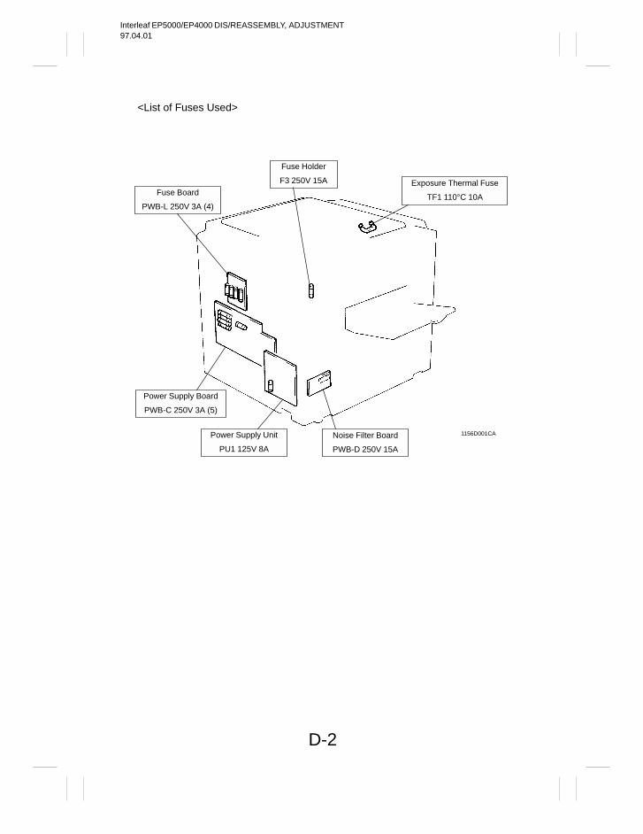
Interleaf EP5000/EP4000 DIS/REASSEMBLY, ADJUSTMENT97.04.01
D-2
Fuse Board
PWB-L 250V 3A (4)
Power Supply Board
PWB-C 250V 3A (5)
Power Supply Unit
PU1 125V 8A
Noise Filter Board
PWB-D 250V 15A
Exposure Thermal Fuse
TF1 110°C 10A
Fuse Holder
F3 250V 15A
<List of Fuses Used>
1156D001CA
Interleaf EP5000/EP4000 DIS/REASSEMBLY, ADJUSTMENT97.04.01
D-3
1139SBD0102A
1-2. INSTRUCTIONS FOR HANDLING THE PWBs WITH MOS ICsThe following precautions must be observed when handling P.W. Boards with MOS (Metal OxideSemiconductor) ICs.
During Transportation/Storage: During transportation or when in storage, new P.W. Boards must not be indiscriminately removed from
their protective conductive bags. Do not store or place P.W. Boards in a location exposed to direct sunlight. When it becomes absolutely necessary to remove a Board from its conductive bag or case, always place
it on its conductive mat in an area as free as possible from static electricity. Do not touch the pins of the ICs with your bare hands.
During Replacement: Before unplugging connectors from the P.W. Boards, make sure that the power cord has been unplugged
from the outlet. When removing a Board from its conductive bag or conductive case, do not touch the pins of the ICs or
the printed pattern. Place it in position by holding only the edges of the Board. Before plugging connectors into the Board, make sure that the power cord has been unplugged from the
power outlet.
During Inspection:
Avoid checking the IC directly with a multimeter; use connectors on the Board. Never create a closed circuit across IC pins with a metal tool. When it is absolutely necessary to touch the ICs and other electrical components on the Board, be sure
to ground your body.
1151SBD0103A
1-3. HANDLING OF THE PC DRUMDuring Transportation/Storage: Use the specified carton whenever moving or storing the PC Drum. The storage temperature is in the range between –20°C and +40°C. In summer, avoid leaving the PC Drum in a car for a long time.
Handling: Ensure that the correct PC Drum is used. Whenever the PC Drum has been removed from the copier, store it in its container or protect it with a Drum
Cloth. The PC Drum exhibits greatest light fatigue after being exposed to strong light over an extended period
of time. Never, therefore, expose it to direct sunlight. Use care not to contaminate the surface of the PC Drum with oil-base solvent, fingerprints, and other for-
eign matter. Do not scratch the surface of the PC Drum. Do not apply chemicals to the surface of the PC Drum. Do not attempt to wipe clean the surface of the PC Drum.
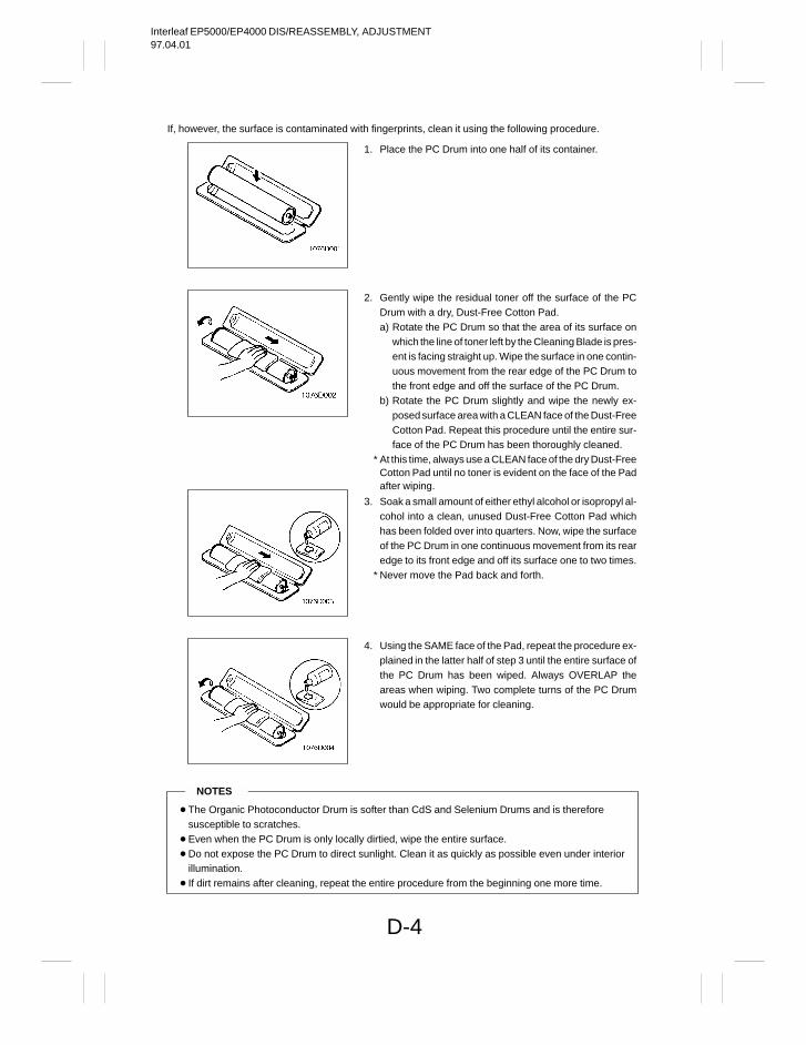
Interleaf EP5000/EP4000 DIS/REASSEMBLY, ADJUSTMENT97.04.01
D-4
If, however, the surface is contaminated with fingerprints, clean it using the following procedure.
NOTES
The Organic Photoconductor Drum is softer than CdS and Selenium Drums and is thereforesusceptible to scratches.
Even when the PC Drum is only locally dirtied, wipe the entire surface. Do not expose the PC Drum to direct sunlight. Clean it as quickly as possible even under interior
illumination. If dirt remains after cleaning, repeat the entire procedure from the beginning one more time.
1. Place the PC Drum into one half of its container.
2. Gently wipe the residual toner off the surface of the PCDrum with a dry, Dust-Free Cotton Pad.a) Rotate the PC Drum so that the area of its surface on
which the line of toner left by the Cleaning Blade is pres-ent is facing straight up. Wipe the surface in one contin-uous movement from the rear edge of the PC Drum tothe front edge and off the surface of the PC Drum.
b) Rotate the PC Drum slightly and wipe the newly ex-posed surface area with a CLEAN face of the Dust-FreeCotton Pad. Repeat this procedure until the entire sur-face of the PC Drum has been thoroughly cleaned.
* At this time, always use a CLEAN face of the dry Dust-FreeCotton Pad until no toner is evident on the face of the Padafter wiping.
3. Soak a small amount of either ethyl alcohol or isopropyl al-cohol into a clean, unused Dust-Free Cotton Pad whichhas been folded over into quarters. Now, wipe the surfaceof the PC Drum in one continuous movement from its rearedge to its front edge and off its surface one to two times.
* Never move the Pad back and forth.
4. Using the SAME face of the Pad, repeat the procedure ex-plained in the latter half of step 3 until the entire surface ofthe PC Drum has been wiped. Always OVERLAP theareas when wiping. Two complete turns of the PC Drumwould be appropriate for cleaning.
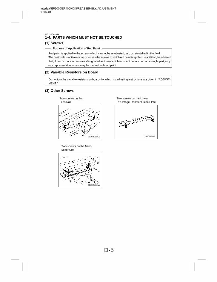
Interleaf EP5000/EP4000 DIS/REASSEMBLY, ADJUSTMENT97.04.01
D-5
1151SBD0104A
1-4. PARTS WHICH MUST NOT BE TOUCHED
(1) ScrewsPurpose of Application of Red Paint
Red paint is applied to the screws which cannot be readjusted, set, or reinstalled in the field.The basic rule is not to remove or loosen the screws to which red paint is applied. In addition, be advisedthat, if two or more screws are designated as those which must not be touched on a single part, onlyone representative screw may be marked with red paint.
(2) Variable Resistors on Board
Do not turn the variable resistors on boards for which no adjusting instructions are given in “ADJUST-MENT.”
(3) Other Screws
Two screws on the LowerPre-Image Transfer Guide Plate
1136D069AA1136D068AA
Two screws on the Mirror Motor Unit
1136D070AA
Two screws on the Lens Rail
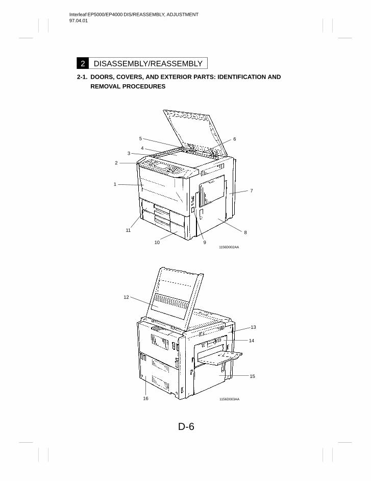
Interleaf EP5000/EP4000 DIS/REASSEMBLY, ADJUSTMENT97.04.01
D-6
DISASSEMBLY/REASSEMBLY2
2-1. DOORS, COVERS, AND EXTERIOR PARTS: IDENTIFICATION AND
REMOVAL PROCEDURES
12
13
14
15
16
11
5
43
2
1
1156D002AA
1156D003AA
7
8
10
6
9
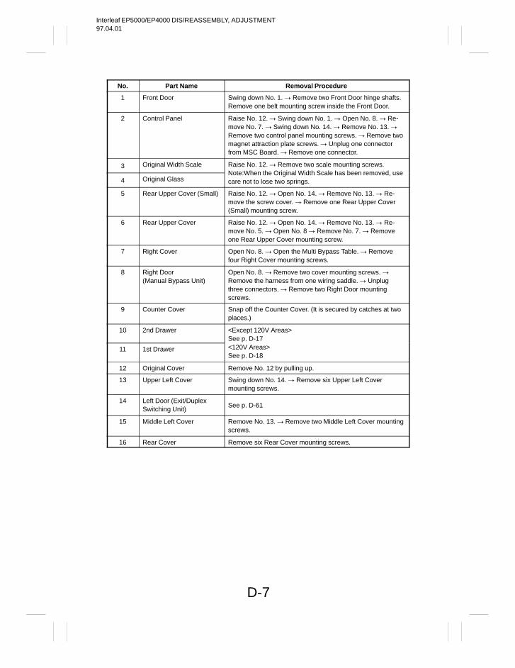
Interleaf EP5000/EP4000 DIS/REASSEMBLY, ADJUSTMENT97.04.01
D-7
No. Part Name Removal Procedure
1 Front Door Swing down No. 1. Remove two Front Door hinge shafts.Remove one belt mounting screw inside the Front Door.
2 Control Panel Raise No. 12. Swing down No. 1. Open No. 8. Re-move No. 7. Swing down No. 14. Remove No. 13. Remove two control panel mounting screws. Remove twomagnet attraction plate screws. Unplug one connectorfrom MSC Board. Remove one connector.
3 Original Width Scale Raise No. 12. Remove two scale mounting screws.
4 Original GlassNote:When the Original Width Scale has been removed, usecare not to lose two springs.
5 Rear Upper Cover (Small) Raise No. 12. Open No. 14. Remove No. 13. Re-move the screw cover. Remove one Rear Upper Cover(Small) mounting screw.
6 Rear Upper Cover Raise No. 12. Open No. 14. Remove No. 13. Re-move No. 5. Open No. 8 Remove No. 7. Removeone Rear Upper Cover mounting screw.
7 Right Cover Open No. 8. Open the Multi Bypass Table. Removefour Right Cover mounting screws.
8 Right Door(Manual Bypass Unit)
Open No. 8. Remove two cover mounting screws. Remove the harness from one wiring saddle. Unplugthree connectors. Remove two Right Door mountingscrews.
9 Counter Cover Snap off the Counter Cover. (It is secured by catches at twoplaces.)
10 2nd Drawer <Except 120V Areas>See p. D-17
11 1st Drawer <120V Areas>See p. D-18
12 Original Cover Remove No. 12 by pulling up.
13 Upper Left Cover Swing down No. 14. Remove six Upper Left Covermounting screws.
14 Left Door (Exit/DuplexSwitching Unit)
See p. D-61
15 Middle Left Cover Remove No. 13. Remove two Middle Left Cover mountingscrews.
16 Rear Cover Remove six Rear Cover mounting screws.
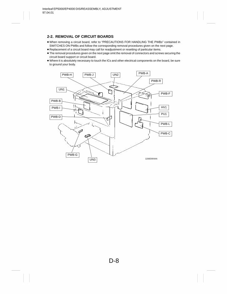
Interleaf EP5000/EP4000 DIS/REASSEMBLY, ADJUSTMENT97.04.01
D-8
2-2. REMOVAL OF CIRCUIT BOARDS When removing a circuit board, refer to “PRECAUTIONS FOR HANDLING THE PWBs” contained in
SWITCHES ON PWBs and follow the corresponding removal procedures given on the next page. Replacement of a circuit board may call for readjustment or resetting of particular items. The removal procedures given on the next page omit the removal of connectors and screws securing the
circuit board support or circuit board. Where it is absolutely necessary to touch the ICs and other electrical components on the board, be sure
to ground your body.
1156D004AA
PWB-H PWB-J UN2 PWB-A
PWB-R
PWB-F
HV1
PU1
PWB-L
PWB-C
UN3
PWB-G
PWB-D
PWB-I
PWB-B
UN1
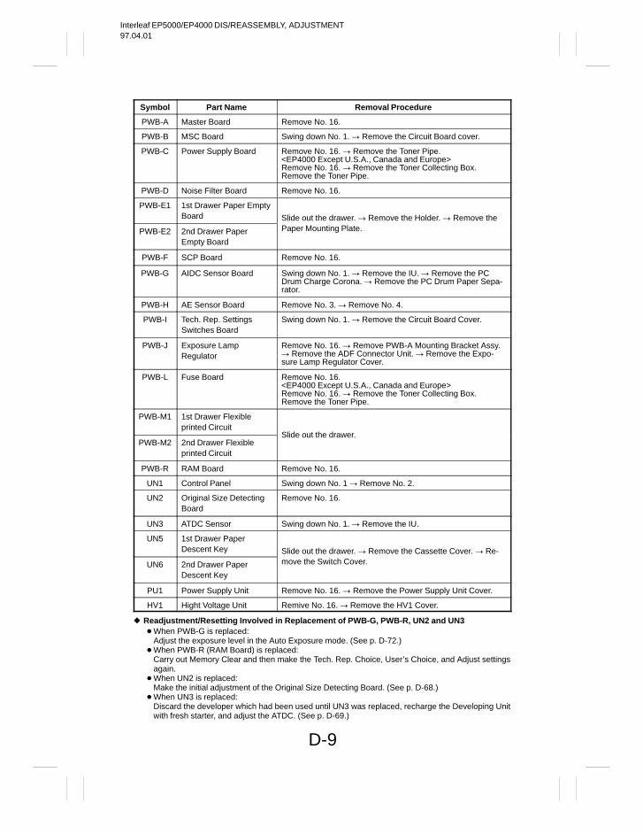
Interleaf EP5000/EP4000 DIS/REASSEMBLY, ADJUSTMENT97.04.01
D-9
Symbol Part Name Removal Procedure
PWB-A Master Board Remove No. 16.
PWB-B MSC Board Swing down No. 1. Remove the Circuit Board cover.
PWB-C Power Supply Board Remove No. 16. Remove the Toner Pipe.<EP4000 Except U.S.A., Canada and Europe>Remove No. 16. Remove the Toner Collecting Box.Remove the Toner Pipe.
PWB-D Noise Filter Board Remove No. 16.
PWB-E1 1st Drawer Paper EmptyBoard Slide out the drawer. Remove the Holder. Remove the
PWB-E2 2nd Drawer PaperEmpty Board
Paper Mounting Plate.
PWB-F SCP Board Remove No. 16.
PWB-G AIDC Sensor Board Swing down No. 1. Remove the IU. Remove the PCDrum Charge Corona. Remove the PC Drum Paper Sepa-rator.
PWB-H AE Sensor Board Remove No. 3. Remove No. 4.
PWB-I Tech. Rep. SettingsSwitches Board
Swing down No. 1. Remove the Circuit Board Cover.
PWB-J Exposure Lamp Regulator
Remove No. 16. Remove PWB-A Mounting Bracket Assy. Remove the ADF Connector Unit. Remove the Expo-sure Lamp Regulator Cover.
PWB-L Fuse Board Remove No. 16.<EP4000 Except U.S.A., Canada and Europe>Remove No. 16. Remove the Toner Collecting Box.Remove the Toner Pipe.
PWB-M1 1st Drawer Flexibleprinted Circuit
PWB-M2 2nd Drawer Flexibleprinted Circuit
Slide out the drawer.
PWB-R RAM Board Remove No. 16.
UN1 Control Panel Swing down No. 1 Remove No. 2.
UN2 Original Size DetectingBoard
Remove No. 16.
UN3 ATDC Sensor Swing down No. 1. Remove the IU.
UN5 1st Drawer Paper Descent Key Slide out the drawer. Remove the Cassette Cover. Re-
UN6 2nd Drawer Paper Descent Key
move the Switch Cover.
PU1 Power Supply Unit Remove No. 16. Remove the Power Supply Unit Cover.
HV1 Hight Voltage Unit Remive No. 16. Remove the HV1 Cover.
Readjustment/Resetting Involved in Replacement of PWB-G, PWB-R, UN2 and UN3 When PWB-G is replaced:
Adjust the exposure level in the Auto Exposure mode. (See p. D-72.) When PWB-R (RAM Board) is replaced:
Carry out Memory Clear and then make the Tech. Rep. Choice, User’s Choice, and Adjust settingsagain.
When UN2 is replaced: Make the initial adjustment of the Original Size Detecting Board. (See p. D-68.)
When UN3 is replaced: Discard the developer which had been used until UN3 was replaced, recharge the Developing Unitwith fresh starter, and adjust the ATDC. (See p. D-69.)
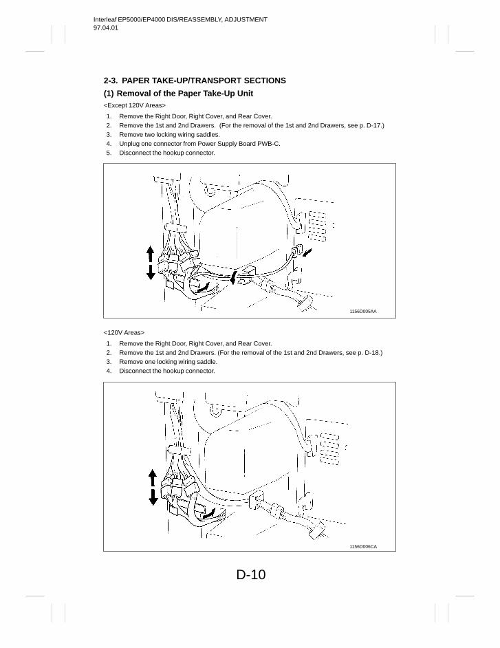
Interleaf EP5000/EP4000 DIS/REASSEMBLY, ADJUSTMENT97.04.01
D-10
2-3. PAPER TAKE-UP/TRANSPORT SECTIONS
(1) Removal of the Paper Take-Up Unit<Except 120V Areas>
1. Remove the Right Door, Right Cover, and Rear Cover.2. Remove the 1st and 2nd Drawers. (For the removal of the 1st and 2nd Drawers, see p. D-17.)3. Remove two locking wiring saddles.4. Unplug one connector from Power Supply Board PWB-C.5. Disconnect the hookup connector.
1156D005AA
<120V Areas>
1. Remove the Right Door, Right Cover, and Rear Cover.2. Remove the 1st and 2nd Drawers. (For the removal of the 1st and 2nd Drawers, see p. D-18.)3. Remove one locking wiring saddle.4. Disconnect the hookup connector.
1156D006CA
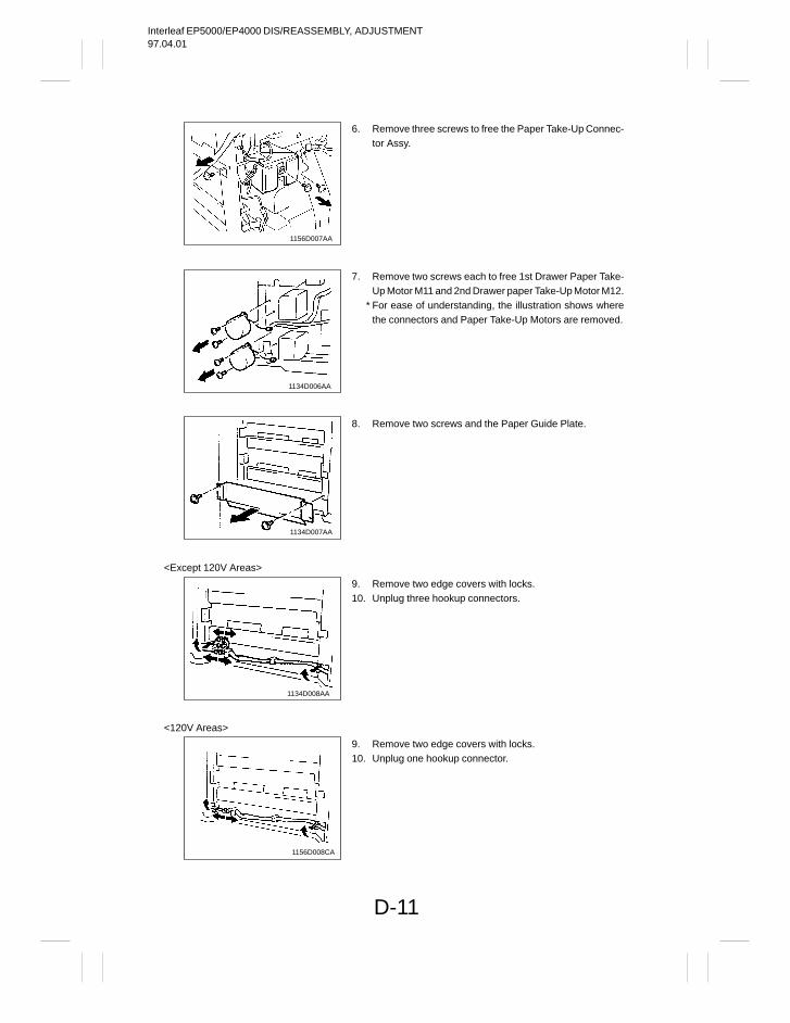
Interleaf EP5000/EP4000 DIS/REASSEMBLY, ADJUSTMENT97.04.01
D-11
1156D007AA
1134D006AA
1134D007AA
<Except 120V Areas>
1134D008AA
<120V Areas>
1156D008CA
6. Remove three screws to free the Paper Take-Up Connec-tor Assy.
7. Remove two screws each to free 1st Drawer Paper Take-Up Motor M11 and 2nd Drawer paper Take-Up Motor M12.
* For ease of understanding, the illustration shows wherethe connectors and Paper Take-Up Motors are removed.
8. Remove two screws and the Paper Guide Plate.
9. Remove two edge covers with locks.10. Unplug three hookup connectors.
9. Remove two edge covers with locks.10. Unplug one hookup connector.
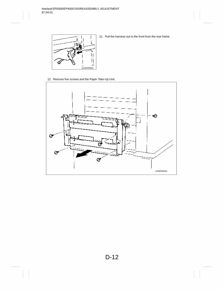
Interleaf EP5000/EP4000 DIS/REASSEMBLY, ADJUSTMENT97.04.01
D-12
1134D009AA
12. Remove five screws and the Paper Take-Up Unit.
1156D009AA
11. Pull the harness out to the front from the rear frame.
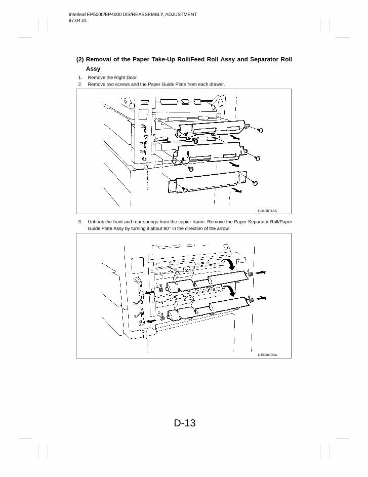
Interleaf EP5000/EP4000 DIS/REASSEMBLY, ADJUSTMENT97.04.01
D-13
(2) Removal of the Paper Take-Up Roll/Feed Roll Assy and Separator Roll
Assy1. Remove the Right Door.2. Remove two screws and the Paper Guide Plate from each drawer.
1134D011AA
3. Unhook the front and rear springs from the copier frame. Remove the Paper Separator Roll/PaperGuide Plate Assy by turning it about 90 in the direction of the arrow.
1156D010AA
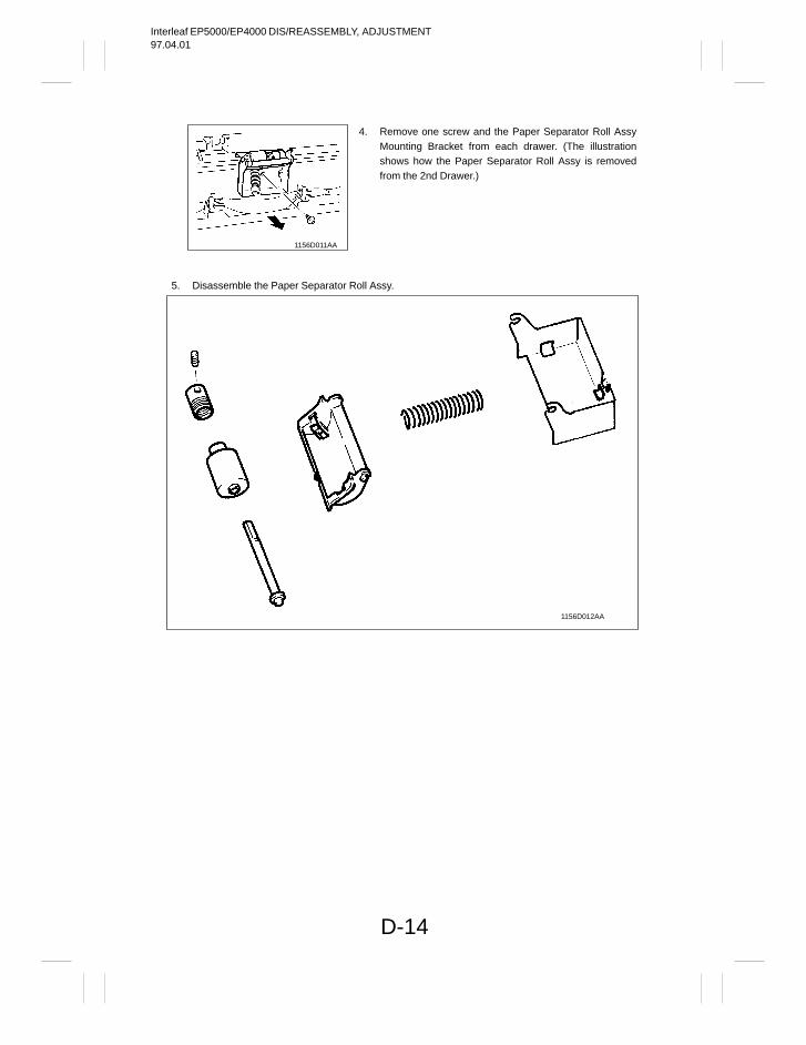
Interleaf EP5000/EP4000 DIS/REASSEMBLY, ADJUSTMENT97.04.01
D-14
1156D011AA
5. Disassemble the Paper Separator Roll Assy.
1156D012AA
4. Remove one screw and the Paper Separator Roll AssyMounting Bracket from each drawer. (The illustrationshows how the Paper Separator Roll Assy is removedfrom the 2nd Drawer.)
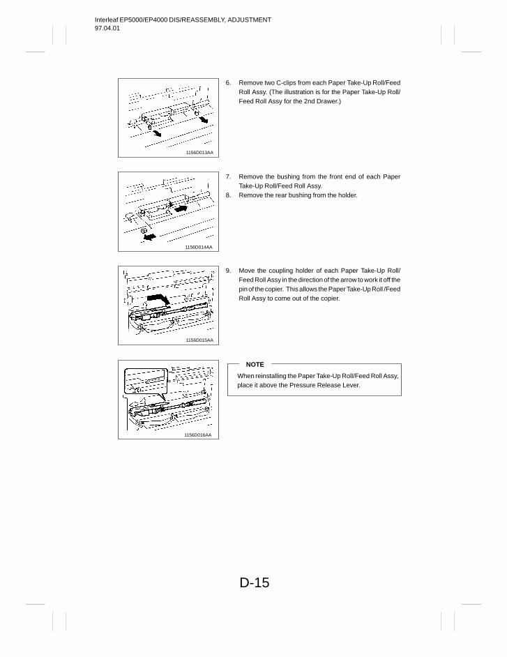
Interleaf EP5000/EP4000 DIS/REASSEMBLY, ADJUSTMENT97.04.01
D-15
1156D013AA
1156D014AA
1156D015AA
1156D016AA
6. Remove two C-clips from each Paper Take-Up Roll/FeedRoll Assy. (The illustration is for the Paper Take-Up Roll/Feed Roll Assy for the 2nd Drawer.)
7. Remove the bushing from the front end of each PaperTake-Up Roll/Feed Roll Assy.
8. Remove the rear bushing from the holder.
9. Move the coupling holder of each Paper Take-Up Roll/Feed Roll Assy in the direction of the arrow to work it off thepin of the copier. This allows the Paper Take-Up Roll /FeedRoll Assy to come out of the copier.
NOTE
When reinstalling the Paper Take-Up Roll/Feed Roll Assy,place it above the Pressure Release Lever.
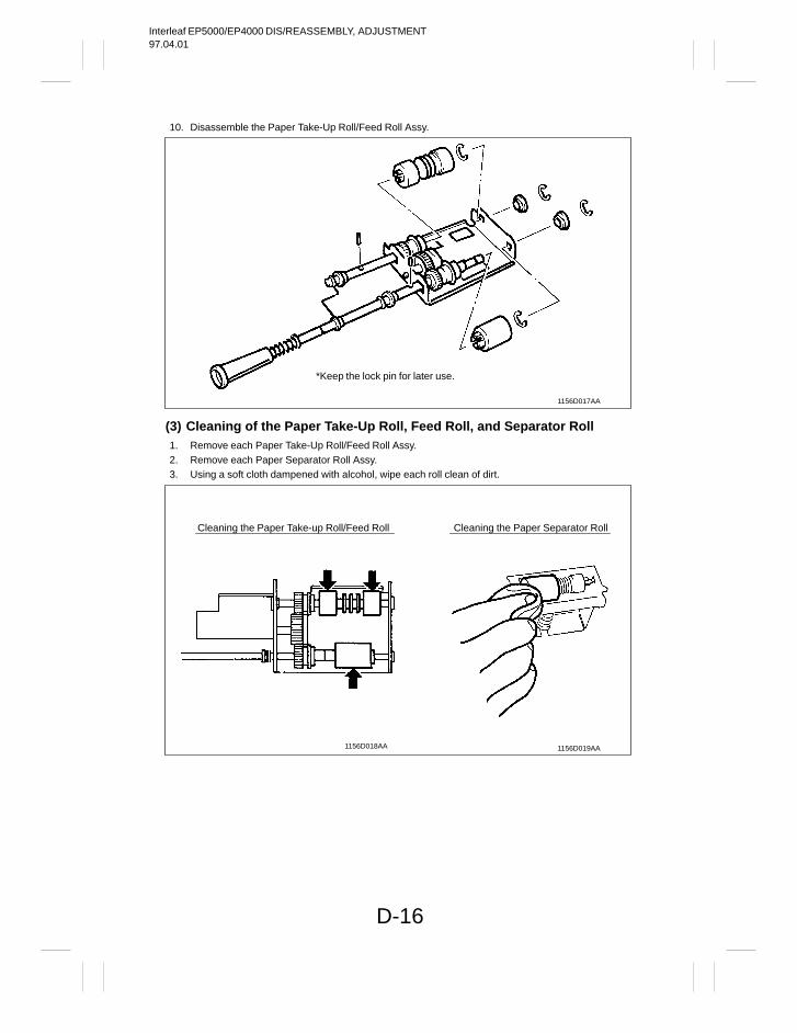
Interleaf EP5000/EP4000 DIS/REASSEMBLY, ADJUSTMENT97.04.01
D-16
10. Disassemble the Paper Take-Up Roll/Feed Roll Assy.
1156D017AA
*Keep the lock pin for later use.
(3) Cleaning of the Paper Take-Up Roll, Feed Roll, and Separator Roll1. Remove each Paper Take-Up Roll/Feed Roll Assy.2. Remove each Paper Separator Roll Assy.3. Using a soft cloth dampened with alcohol, wipe each roll clean of dirt.
1156D019AA1156D018AA
Cleaning the Paper Take-up Roll/Feed Roll Cleaning the Paper Separator Roll
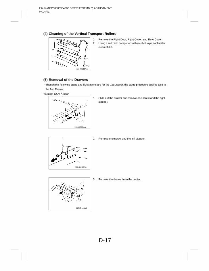
Interleaf EP5000/EP4000 DIS/REASSEMBLY, ADJUSTMENT97.04.01
D-17
(4) Cleaning of the Vertical Transport Rollers
1134D016AA
(5) Removal of the Drawers*Though the following steps and illustrations are for the 1st Drawer, the same procedure applies also to
the 2nd Drawer.
<Except 120V Areas>
1156D020AA
1134D133AA
1134D143AA
1. Remove the Right Door, Right Cover, and Rear Cover.2. Using a soft cloth dampened with alcohol, wipe each roller
clean of dirt.
1. Slide out the drawer and remove one screw and the rightstopper.
2. Remove one screw and the left stopper.
3. Remove the drawer from the copier.
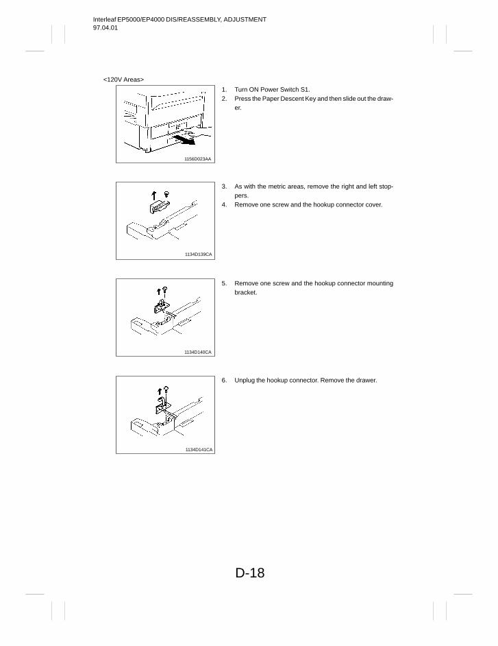
Interleaf EP5000/EP4000 DIS/REASSEMBLY, ADJUSTMENT97.04.01
D-18
<120V Areas>
1156D023AA
1134D139CA
1134D140CA
1134D141CA
1. Turn ON Power Switch S1.2. Press the Paper Descent Key and then slide out the draw-
er.
3. As with the metric areas, remove the right and left stop-pers.
4. Remove one screw and the hookup connector cover.
5. Remove one screw and the hookup connector mountingbracket.
6. Unplug the hookup connector. Remove the drawer.
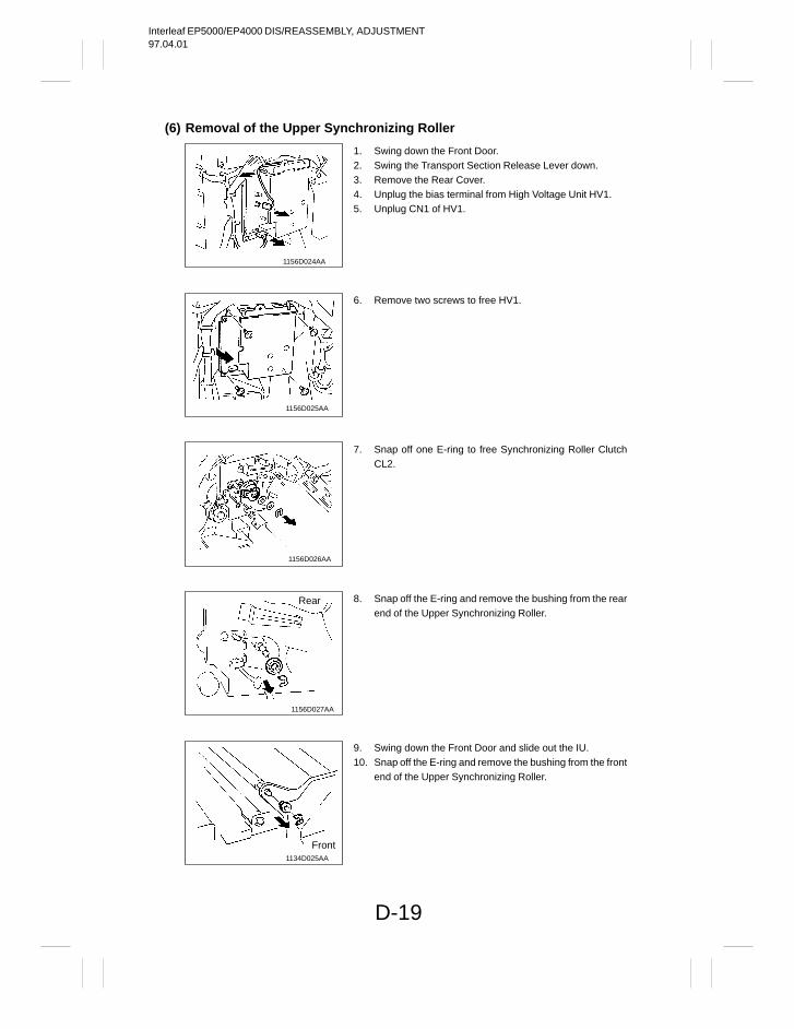
Interleaf EP5000/EP4000 DIS/REASSEMBLY, ADJUSTMENT97.04.01
D-19
(6) Removal of the Upper Synchronizing Roller
1156D024AA
1156D025AA
1156D026AA
1156D027AA
Rear
1134D025AA
Front
1. Swing down the Front Door.2. Swing the Transport Section Release Lever down.3. Remove the Rear Cover.4. Unplug the bias terminal from High Voltage Unit HV1.5. Unplug CN1 of HV1.
6. Remove two screws to free HV1.
7. Snap off one E-ring to free Synchronizing Roller ClutchCL2.
8. Snap off the E-ring and remove the bushing from the rearend of the Upper Synchronizing Roller.
9. Swing down the Front Door and slide out the IU.10. Snap off the E-ring and remove the bushing from the front
end of the Upper Synchronizing Roller.
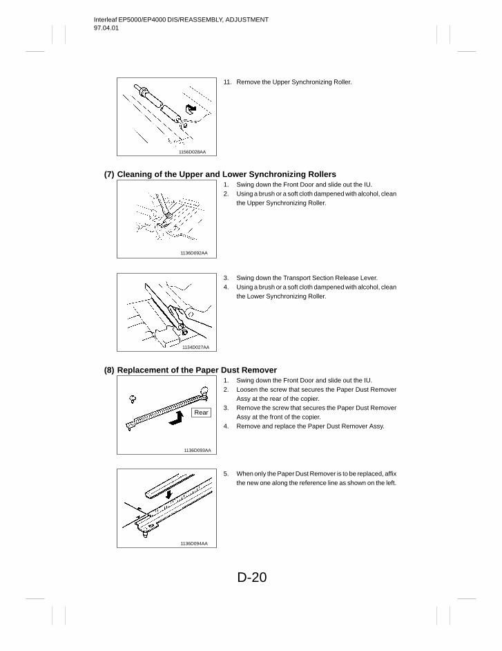
Interleaf EP5000/EP4000 DIS/REASSEMBLY, ADJUSTMENT97.04.01
D-20
1156D028AA
(7) Cleaning of the Upper and Lower Synchronizing Rollers
1136D092AA
1134D027AA
(8) Replacement of the Paper Dust Remover
1136D093AA
Rear
1136D094AA
11. Remove the Upper Synchronizing Roller.
1. Swing down the Front Door and slide out the IU.2. Using a brush or a soft cloth dampened with alcohol, clean
the Upper Synchronizing Roller.
3. Swing down the Transport Section Release Lever.4. Using a brush or a soft cloth dampened with alcohol, clean
the Lower Synchronizing Roller.
1. Swing down the Front Door and slide out the IU.2. Loosen the screw that secures the Paper Dust Remover
Assy at the rear of the copier.3. Remove the screw that secures the Paper Dust Remover
Assy at the front of the copier.4. Remove and replace the Paper Dust Remover Assy.
5. When only the Paper Dust Remover is to be replaced, affixthe new one along the reference line as shown on the left.
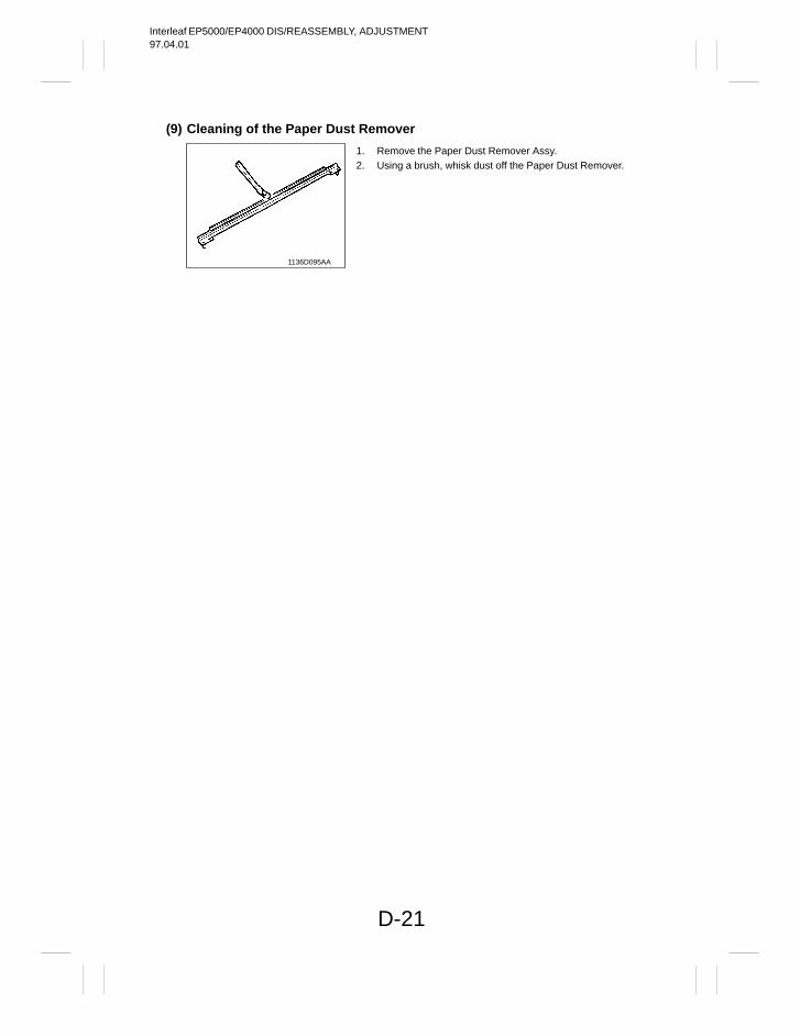
Interleaf EP5000/EP4000 DIS/REASSEMBLY, ADJUSTMENT97.04.01
D-21
(9) Cleaning of the Paper Dust Remover
1136D095AA
1. Remove the Paper Dust Remover Assy.2. Using a brush, whisk dust off the Paper Dust Remover.
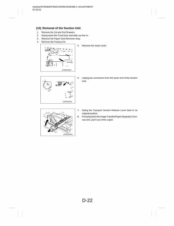
Interleaf EP5000/EP4000 DIS/REASSEMBLY, ADJUSTMENT97.04.01
D-22
(10) Removal of the Suction Unit1. Remove the 1st and 2nd Drawers.2. Swing down the Front Door and slide out the IU.3. Remove the Paper Dust Remover Assy.4. Remove the Fusing Unit.
1156D029AA
1156D030AA
1156D031AA
5. Remove the motor cover.
6. Unplug two connectors from the lower end of the SuctionUnit.
7. Swing the Transport Section Release Lever back to itsoriginal position.
8. Pressing down the Image Transfer/Paper Separator Coro-nas Unit, pull it out of the copier.
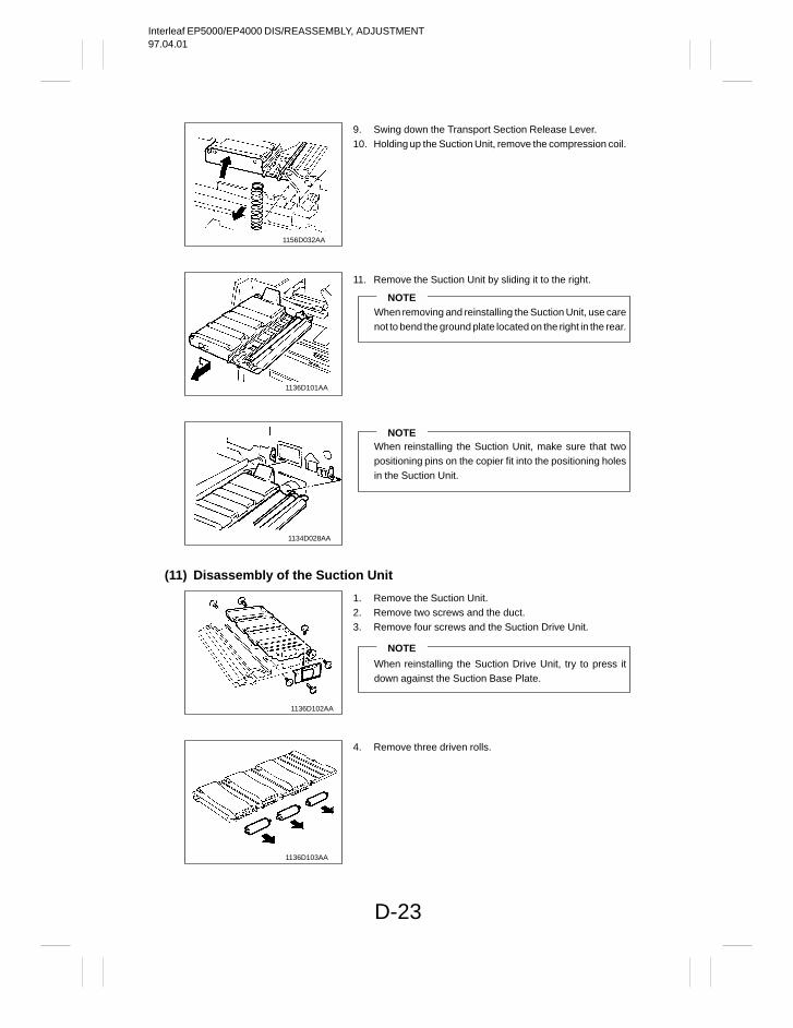
Interleaf EP5000/EP4000 DIS/REASSEMBLY, ADJUSTMENT97.04.01
D-23
1156D032AA
1136D101AA
1134D028AA
(11) Disassembly of the Suction Unit
1136D102AA
1136D103AA
9. Swing down the Transport Section Release Lever.10. Holding up the Suction Unit, remove the compression coil.
11. Remove the Suction Unit by sliding it to the right.
NOTEWhen removing and reinstalling the Suction Unit, use carenot to bend the ground plate located on the right in the rear.
NOTEWhen reinstalling the Suction Unit, make sure that twopositioning pins on the copier fit into the positioning holesin the Suction Unit.
1. Remove the Suction Unit.2. Remove two screws and the duct.3. Remove four screws and the Suction Drive Unit.
NOTE
When reinstalling the Suction Drive Unit, try to press itdown against the Suction Base Plate.
4. Remove three driven rolls.
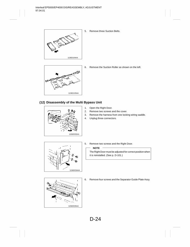
Interleaf EP5000/EP4000 DIS/REASSEMBLY, ADJUSTMENT97.04.01
D-24
1136D104AA
1136D105AA
(12) Disassembly of the Multi Bypass Unit
1156D033AA
1156D034AA
1156D035AA
5. Remove three Suction Belts.
6. Remove the Suction Roller as shown on the left.
1. Open the Right Door.2. Remove two screws and the cover.3. Remove the harness from one locking wiring saddle.4. Unplug three connectors.
5. Remove two screws and the Right Door.
NOTE
The Right Door must be adjusted for correct position whenit is reinstalled. (See p. D-101.)
6. Remove four screws and the Separator Guide Plate Assy.
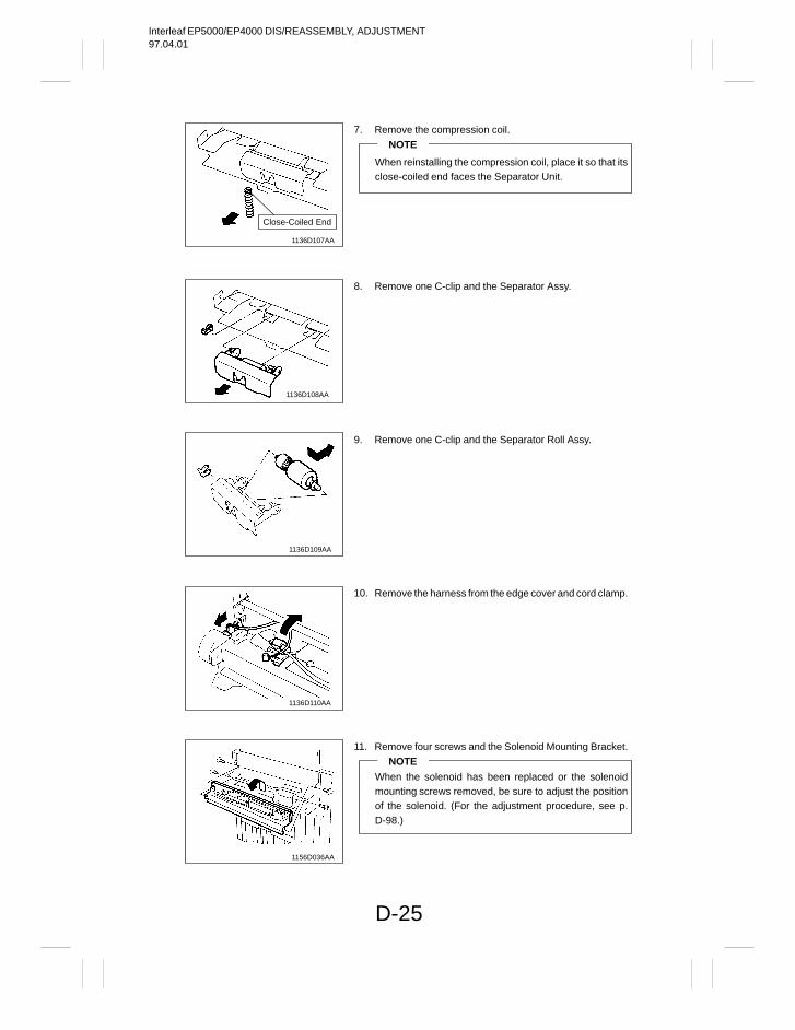
Interleaf EP5000/EP4000 DIS/REASSEMBLY, ADJUSTMENT97.04.01
D-25
1136D107AA
Close-Coiled End
1136D108AA
1136D109AA
1136D110AA
1156D036AA
7. Remove the compression coil.
NOTE
When reinstalling the compression coil, place it so that itsclose-coiled end faces the Separator Unit.
8. Remove one C-clip and the Separator Assy.
9. Remove one C-clip and the Separator Roll Assy.
10. Remove the harness from the edge cover and cord clamp.
11. Remove four screws and the Solenoid Mounting Bracket.
NOTE
When the solenoid has been replaced or the solenoidmounting screws removed, be sure to adjust the positionof the solenoid. (For the adjustment procedure, see p.D-98.)
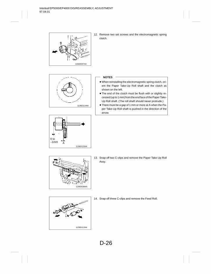
Interleaf EP5000/EP4000 DIS/REASSEMBLY, ADJUSTMENT97.04.01
D-26
1156D037AA
1136D114AA
1136D115AA
0 to –1mm A
1156D038AA
1139D112AA
12. Remove two set screws and the electromagnetic springclutch.
NOTES
When reinstalling the electromagnetic spring clutch, ori-ent the Paper Take-Up Roll shaft and the clutch asshown on the left.
The end of the clutch must be flush with or slightly re-cessed (up to 1 mm) from the end face of the Paper Take-Up Roll shaft. (The roll shaft should never protrude.)
There must be a gap of 1 mm or more at A when the Pa-per Take-Up Roll shaft is pushed in the direction of thearrow.
13. Snap off two C-clips and remove the Paper Take-Up RollAssy.
14. Snap off three C-clips and remove the Feed Roll.
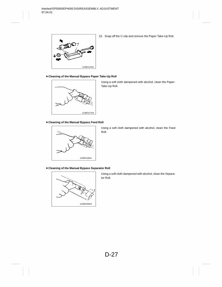
Interleaf EP5000/EP4000 DIS/REASSEMBLY, ADJUSTMENT97.04.01
D-27
1139D113AA
Cleaning of the Manual Bypass Paper Take-Up Roll
1136D117AA
Cleaning of the Manual Bypass Feed Roll
1136D118AA
Cleaning of the Manual Bypass Separator Roll
1156D039AA
15. Snap off the C-clip and remove the Paper Take-Up Roll.
Using a soft cloth dampened with alcohol, clean the Paper-Take-Up Roll.
Using a soft cloth dampened with alcohol, clean the FeedRoll.
Using a soft cloth dampened with alcohol, clean the Separa-tor Roll.
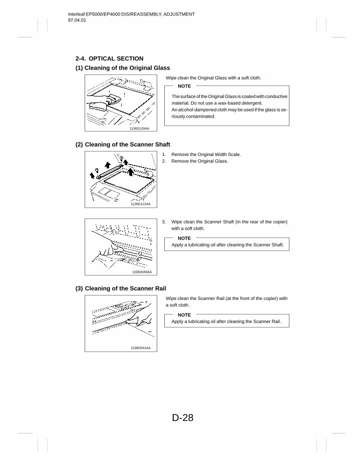
Interleaf EP5000/EP4000 DIS/REASSEMBLY, ADJUSTMENT97.04.01
D-28
2-4. OPTICAL SECTION
(1) Cleaning of the Original Glass
1136D120AA
(2) Cleaning of the Scanner Shaft
1136D121AA
1156D040AA
(3) Cleaning of the Scanner Rail
1156D041AA
Wipe clean the Original Glass with a soft cloth.
NOTE
The surface of the Original Glass is coated with conductivematerial. Do not use a wax-based detergent.An alcohol-dampened cloth may be used if the glass is se-riously contaminated.
1. Remove the Original Width Scale.2. Remove the Original Glass.
3. Wipe clean the Scanner Shaft (in the rear of the copier)with a soft cloth.
NOTEApply a lubricating oil after cleaning the Scanner Shaft.
Wipe clean the Scanner Rail (at the front of the copier) witha soft cloth.
NOTEApply a lubricating oil after cleaning the Scanner Rail.
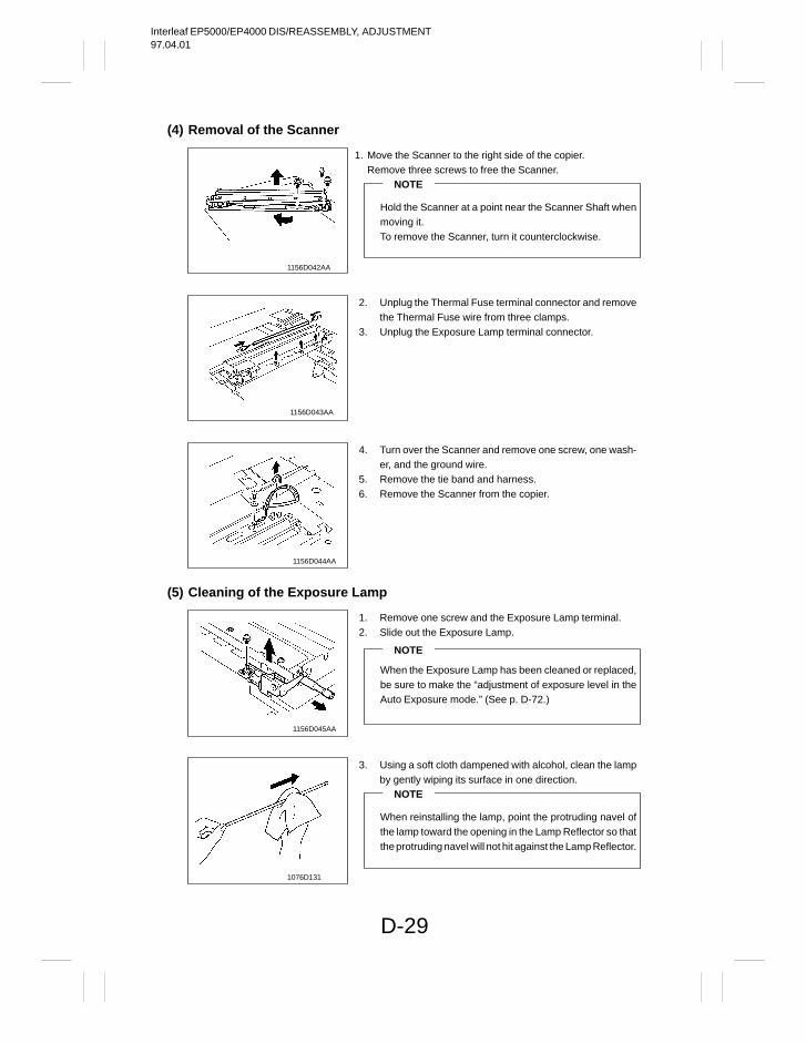
Interleaf EP5000/EP4000 DIS/REASSEMBLY, ADJUSTMENT97.04.01
D-29
(4) Removal of the Scanner
1156D042AA
1156D043AA
1156D044AA
(5) Cleaning of the Exposure Lamp
1156D045AA
1076D131
1. Move the Scanner to the right side of the copier.Remove three screws to free the Scanner.
NOTE
Hold the Scanner at a point near the Scanner Shaft whenmoving it.To remove the Scanner, turn it counterclockwise.
2. Unplug the Thermal Fuse terminal connector and removethe Thermal Fuse wire from three clamps.
3. Unplug the Exposure Lamp terminal connector.
4. Turn over the Scanner and remove one screw, one wash-er, and the ground wire.
5. Remove the tie band and harness.6. Remove the Scanner from the copier.
1. Remove one screw and the Exposure Lamp terminal.2. Slide out the Exposure Lamp.
NOTE
When the Exposure Lamp has been cleaned or replaced,be sure to make the “adjustment of exposure level in theAuto Exposure mode.” (See p. D-72.)
3. Using a soft cloth dampened with alcohol, clean the lampby gently wiping its surface in one direction.
NOTE
When reinstalling the lamp, point the protruding navel ofthe lamp toward the opening in the Lamp Reflector so thatthe protruding navel will not hit against the Lamp Reflector.
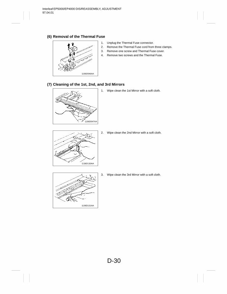
Interleaf EP5000/EP4000 DIS/REASSEMBLY, ADJUSTMENT97.04.01
D-30
(6) Removal of the Thermal Fuse
1156D046AA
(7) Cleaning of the 1st, 2nd, and 3rd Mirrors
1156D047AA
1136D130AA
1136D131AA
1. Unplug the Thermal Fuse connector.2. Remove the Thermal Fuse cord from three clamps.3. Remove one screw and Thermal Fuse cover.4. Remove two screws and the Thermal Fuse.
1. Wipe clean the 1st Mirror with a soft cloth.
2. Wipe clean the 2nd Mirror with a soft cloth.
3. Wipe clean the 3rd Mirror with a soft cloth.
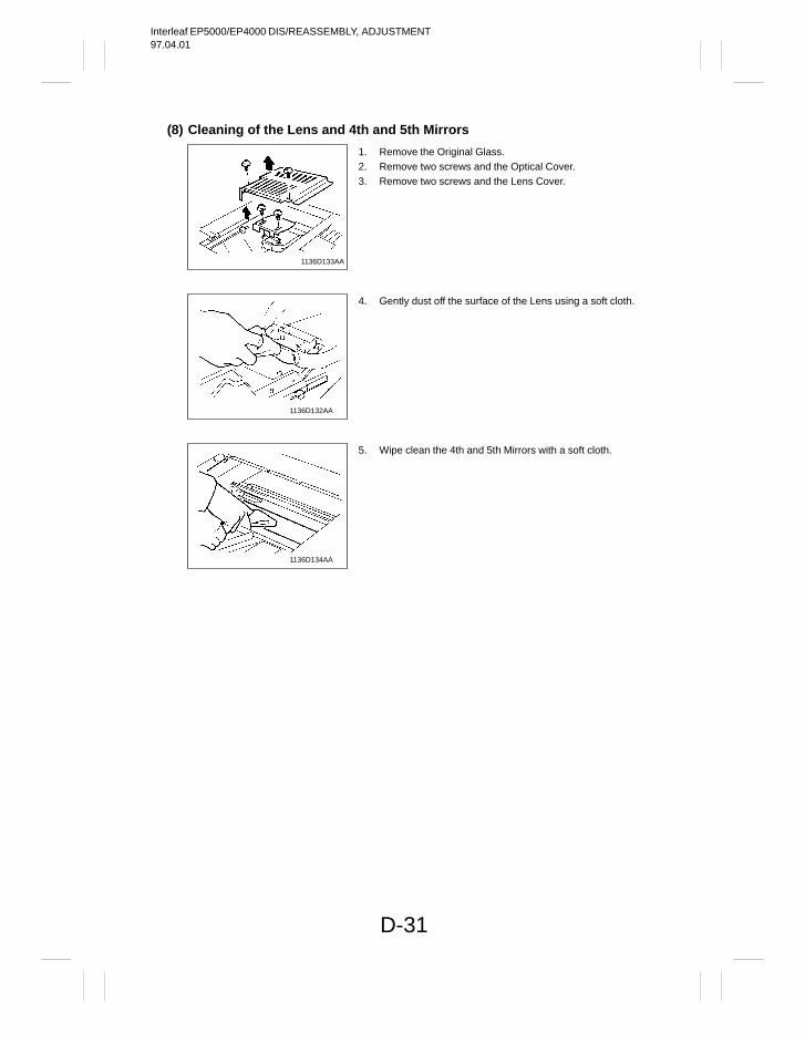
Interleaf EP5000/EP4000 DIS/REASSEMBLY, ADJUSTMENT97.04.01
D-31
(8) Cleaning of the Lens and 4th and 5th Mirrors
1136D133AA
1136D132AA
1136D134AA
1. Remove the Original Glass.2. Remove two screws and the Optical Cover.3. Remove two screws and the Lens Cover.
4. Gently dust off the surface of the Lens using a soft cloth.
5. Wipe clean the 4th and 5th Mirrors with a soft cloth.
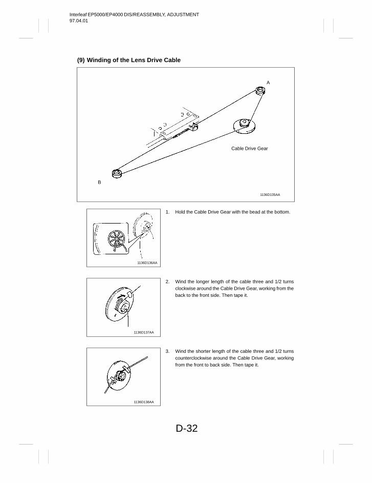
Interleaf EP5000/EP4000 DIS/REASSEMBLY, ADJUSTMENT97.04.01
D-32
(9) Winding of the Lens Drive Cable
1136D135AA
Cable Drive Gear
A
B
1136D136AA
1136D137AA
1136D138AA
1. Hold the Cable Drive Gear with the bead at the bottom.
2. Wind the longer length of the cable three and 1/2 turnsclockwise around the Cable Drive Gear, working from theback to the front side. Then tape it.
3. Wind the shorter length of the cable three and 1/2 turnscounterclockwise around the Cable Drive Gear, workingfrom the front to back side. Then tape it.
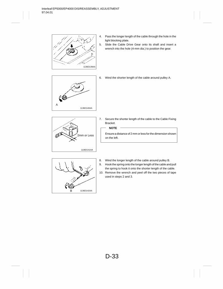
Interleaf EP5000/EP4000 DIS/REASSEMBLY, ADJUSTMENT97.04.01
D-33
1136D139AA
1136D140AA
A
1136D141AA
2mm or Less
1136D142AAB
4. Pass the longer length of the cable through the hole in thelight blocking plate.
5. Slide the Cable Drive Gear onto its shaft and insert awrench into the hole (4-mm dia.) to position the gear.
6. Wind the shorter length of the cable around pulley A.
7. Secure the shorter length of the cable to the Cable FixingBracket.
NOTE
Ensure a distance of 2 mm or less for the dimension shownon the left.
8. Wind the longer length of the cable around pulley B.9. Hook the spring onto the longer length of the cable and pull
the spring to hook it onto the shorter length of the cable.10. Remove the wrench and peel off the two pieces of tape
used in steps 2 and 3.
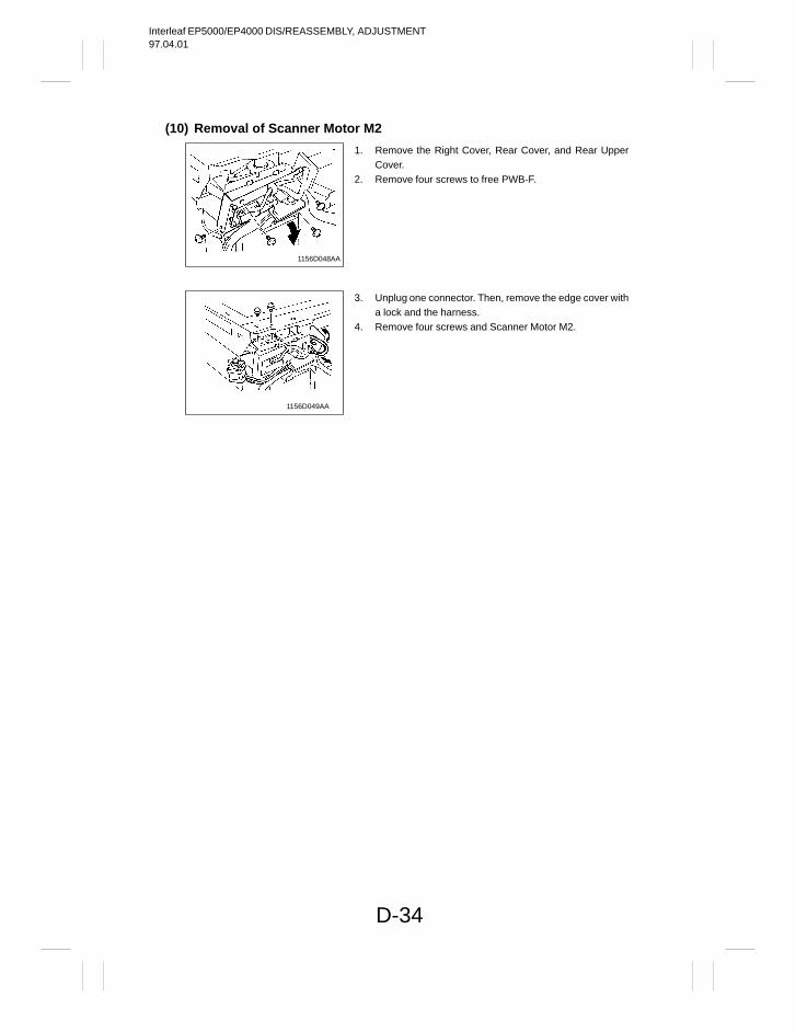
Interleaf EP5000/EP4000 DIS/REASSEMBLY, ADJUSTMENT97.04.01
D-34
(10) Removal of Scanner Motor M2
1156D048AA
1156D049AA
1. Remove the Right Cover, Rear Cover, and Rear UpperCover.
2. Remove four screws to free PWB-F.
3. Unplug one connector. Then, remove the edge cover witha lock and the harness.
4. Remove four screws and Scanner Motor M2.
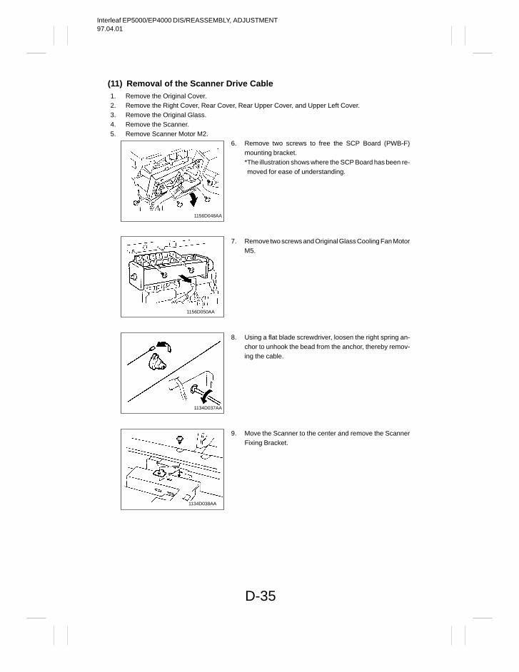
Interleaf EP5000/EP4000 DIS/REASSEMBLY, ADJUSTMENT97.04.01
D-35
(11) Removal of the Scanner Drive Cable1. Remove the Original Cover.2. Remove the Right Cover, Rear Cover, Rear Upper Cover, and Upper Left Cover.3. Remove the Original Glass.4. Remove the Scanner.5. Remove Scanner Motor M2.
1156D048AA
1156D050AA
1134D037AA
1134D038AA
6. Remove two screws to free the SCP Board (PWB-F)mounting bracket.*The illustration shows where the SCP Board has been re-moved for ease of understanding.
7. Remove two screws and Original Glass Cooling Fan MotorM5.
8. Using a flat blade screwdriver, loosen the right spring an-chor to unhook the bead from the anchor, thereby remov-ing the cable.
9. Move the Scanner to the center and remove the ScannerFixing Bracket.
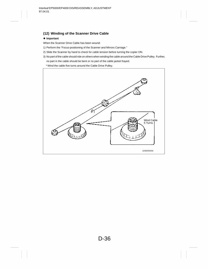
Interleaf EP5000/EP4000 DIS/REASSEMBLY, ADJUSTMENT97.04.01
D-36
(12) Winding of the Scanner Drive Cable Important
When the Scanner Drive Cable has been wound:
1) Perform the “Focus-positioning of the Scanner and Mirrors Carriage.”
2) Slide the Scanner by hand to check for cable tension before turning the copier ON.
3) No part of the cable should ride on others when winding the cable around the Cable Drive Pulley. Further,
no part in the cable should be bent or no part of the cable jacket frayed.
* Wind the cable five turns around the Cable Drive Pulley.
1156D054AA
Wind Cable5 Turns.
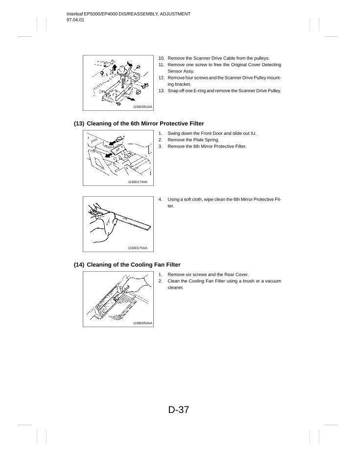
Interleaf EP5000/EP4000 DIS/REASSEMBLY, ADJUSTMENT97.04.01
D-37
1156D051AA
(13) Cleaning of the 6th Mirror Protective Filter
1156D174AA
1156D175AA
(14) Cleaning of the Cooling Fan Filter
1156D052AA
10. Remove the Scanner Drive Cable from the pulleys.11. Remove one screw to free the Original Cover Detecting
Sensor Assy.12. Remove four screws and the Scanner Drive Pulley mount-
ing bracket.13. Snap off one E-ring and remove the Scanner Drive Pulley.
1. Swing down the Front Door and slide out IU.2. Remove the Plate Spring.3. Remove the 6th Mirror Protective Filter.
4. Using a soft cloth, wipe clean the 6th Mirror Protective Fil-ter.
1. Remove six screws and the Rear Cover.2. Clean the Cooling Fan Filter using a brush or a vacuum
cleaner.
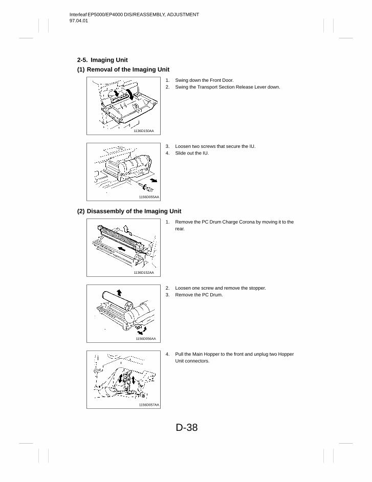
Interleaf EP5000/EP4000 DIS/REASSEMBLY, ADJUSTMENT97.04.01
D-38
2-5. Imaging Unit
(1) Removal of the Imaging Unit
1136D150AA
1156D055AA
(2) Disassembly of the Imaging Unit
1136D152AA
1156D056AA
1156D057AA
1. Swing down the Front Door.2. Swing the Transport Section Release Lever down.
3. Loosen two screws that secure the IU.4. Slide out the IU.
1. Remove the PC Drum Charge Corona by moving it to therear.
2. Loosen one screw and remove the stopper.3. Remove the PC Drum.
4. Pull the Main Hopper to the front and unplug two HopperUnit connectors.
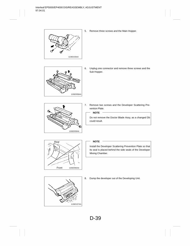
Interleaf EP5000/EP4000 DIS/REASSEMBLY, ADJUSTMENT97.04.01
D-39
1136D155AA
1156D058AA
1156D059AA
1156D060AA
Rear
Front
1136D157AA
5. Remove three screws and the Main Hopper.
6. Unplug one connector and remove three screws and theSub Hopper.
7. Remove two screws and the Developer Scattering Pre-vention Plate.
NOTE
Do not remove the Doctor Blade Assy, as a changed Dbcould result.
NOTE
Install the Developer Scattering Prevention Plate so thatits seal is placed behind the side seals of the DeveloperMixing Chamber.
8. Dump the developer out of the Developing Unit.
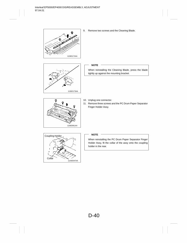
Interleaf EP5000/EP4000 DIS/REASSEMBLY, ADJUSTMENT97.04.01
D-40
1136D172AA
1136D173AA
1156D061AA
1134D047AA
Coupling Holder
Collar
9. Remove two screws and the Cleaning Blade.
NOTE
When reinstalling the Cleaning Blade, press the bladetightly up against the mounting bracket.
10. Unplug one connector.11. Remove three screws and the PC Drum Paper Separator
Finger Holder Assy.
NOTE
When reinstalling the PC Drum Paper Separator FingerHolder Assy, fit the collar of the assy onto the couplingholder in the rear.
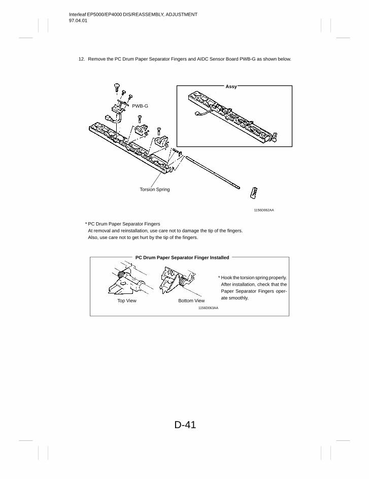
Interleaf EP5000/EP4000 DIS/REASSEMBLY, ADJUSTMENT97.04.01
D-41
12. Remove the PC Drum Paper Separator Fingers and AIDC Sensor Board PWB-G as shown below.
1156D062AA
Torsion Spring
PWB-G
Assy
* PC Drum Paper Separator Fingers At removal and reinstallation, use care not to damage the tip of the fingers.Also, use care not to get hurt by the tip of the fingers.
* Hook the torsion spring properly.After installation, check that thePaper Separator Fingers oper-ate smoothly.
Top View Bottom View1156D063AA
PC Drum Paper Separator Finger Installed
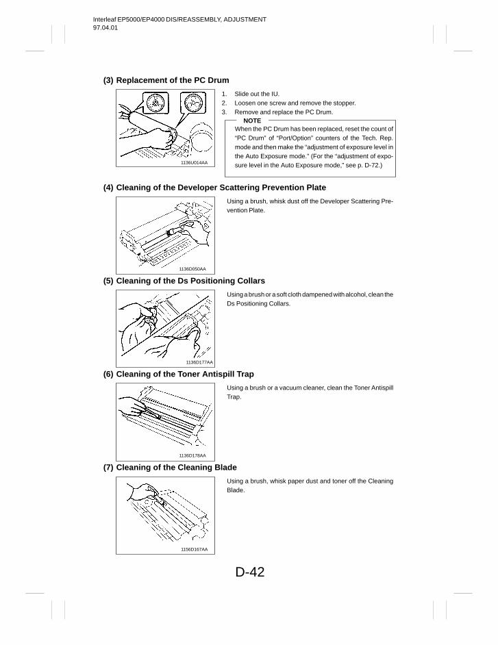
Interleaf EP5000/EP4000 DIS/REASSEMBLY, ADJUSTMENT97.04.01
D-42
(3) Replacement of the PC Drum
1136U014AA
(4) Cleaning of the Developer Scattering Prevention Plate
1136D050AA
(5) Cleaning of the Ds Positioning Collars
1136D177AA
(6) Cleaning of the Toner Antispill Trap
1136D178AA
(7) Cleaning of the Cleaning Blade
1156D167AA
1. Slide out the IU.2. Loosen one screw and remove the stopper.3. Remove and replace the PC Drum.
NOTEWhen the PC Drum has been replaced, reset the count of“PC Drum” of “Port/Option” counters of the Tech. Rep.mode and then make the “adjustment of exposure level inthe Auto Exposure mode.” (For the “adjustment of expo-sure level in the Auto Exposure mode,” see p. D-72.)
Using a brush, whisk dust off the Developer Scattering Pre-vention Plate.
Using a brush or a soft cloth dampened with alcohol, clean theDs Positioning Collars.
Using a brush or a vacuum cleaner, clean the Toner AntispillTrap.
Using a brush, whisk paper dust and toner off the CleaningBlade.
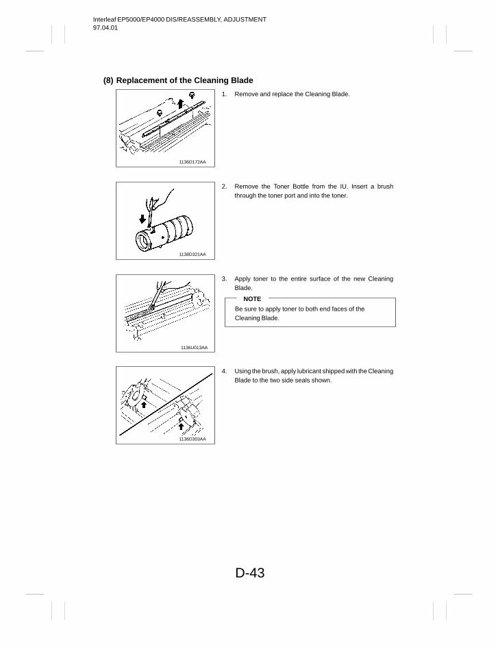
Interleaf EP5000/EP4000 DIS/REASSEMBLY, ADJUSTMENT97.04.01
D-43
(8) Replacement of the Cleaning Blade
1136D172AA
1138D321AA
1136U013AA
1136D303AA
1. Remove and replace the Cleaning Blade.
2. Remove the Toner Bottle from the IU. Insert a brushthrough the toner port and into the toner.
3. Apply toner to the entire surface of the new CleaningBlade.
NOTE
Be sure to apply toner to both end faces of theCleaning Blade.
4. Using the brush, apply lubricant shipped with the CleaningBlade to the two side seals shown.
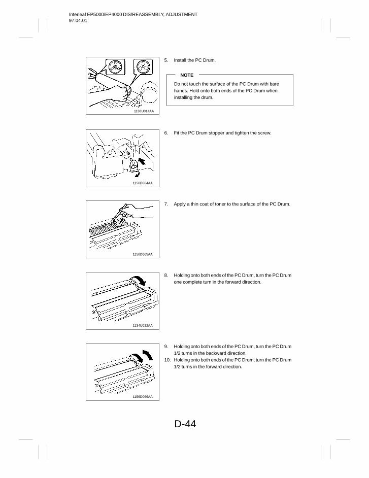
Interleaf EP5000/EP4000 DIS/REASSEMBLY, ADJUSTMENT97.04.01
D-44
1136U014AA
1156D064AA
1156D065AA
1134U022AA
1156D066AA
5. Install the PC Drum.
NOTE
Do not touch the surface of the PC Drum with barehands. Hold onto both ends of the PC Drum wheninstalling the drum.
6. Fit the PC Drum stopper and tighten the screw.
7. Apply a thin coat of toner to the surface of the PC Drum.
8. Holding onto both ends of the PC Drum, turn the PC Drumone complete turn in the forward direction.
9. Holding onto both ends of the PC Drum, turn the PC Drum1/2 turns in the backward direction.
10. Holding onto both ends of the PC Drum, turn the PC Drum1/2 turns in the forward direction.
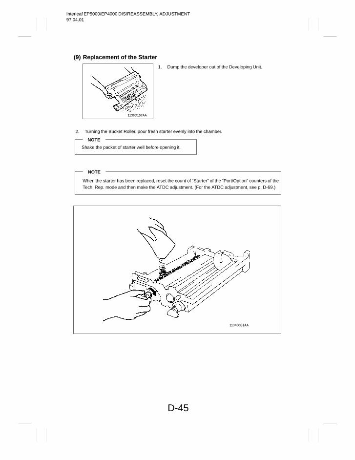
Interleaf EP5000/EP4000 DIS/REASSEMBLY, ADJUSTMENT97.04.01
D-45
(9) Replacement of the Starter
1136D157AA
2. Turning the Bucket Roller, pour fresh starter evenly into the chamber.
NOTE
Shake the packet of starter well before opening it.
NOTE
When the starter has been replaced, reset the count of “Starter” of the “Port/Option” counters of theTech. Rep. mode and then make the ATDC adjustment. (For the ATDC adjustment, see p. D-69.)
1134D051AA
1. Dump the developer out of the Developing Unit.
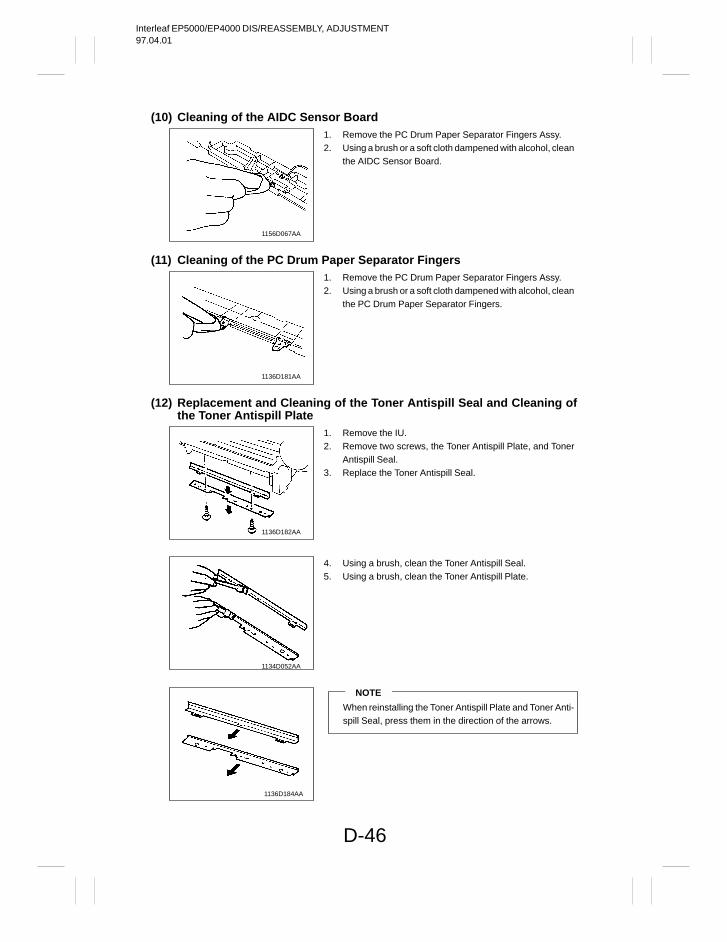
Interleaf EP5000/EP4000 DIS/REASSEMBLY, ADJUSTMENT97.04.01
D-46
(10) Cleaning of the AIDC Sensor Board
1156D067AA
(11) Cleaning of the PC Drum Paper Separator Fingers
1136D181AA
(12) Replacement and Cleaning of the Toner Antispill Seal and Cleaning ofthe Toner Antispill Plate
1136D182AA
1134D052AA
1136D184AA
1. Remove the PC Drum Paper Separator Fingers Assy.2. Using a brush or a soft cloth dampened with alcohol, clean
the AIDC Sensor Board.
1. Remove the PC Drum Paper Separator Fingers Assy.2. Using a brush or a soft cloth dampened with alcohol, clean
the PC Drum Paper Separator Fingers.
1. Remove the IU.2. Remove two screws, the Toner Antispill Plate, and Toner
Antispill Seal.3. Replace the Toner Antispill Seal.
4. Using a brush, clean the Toner Antispill Seal.5. Using a brush, clean the Toner Antispill Plate.
NOTE
When reinstalling the Toner Antispill Plate and Toner Anti-spill Seal, press them in the direction of the arrows.
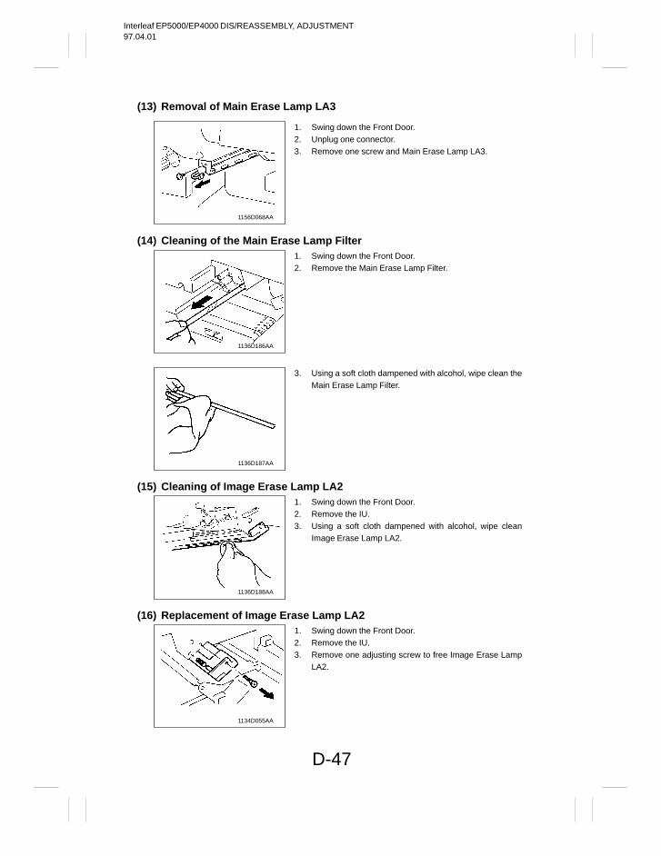
Interleaf EP5000/EP4000 DIS/REASSEMBLY, ADJUSTMENT97.04.01
D-47
(13) Removal of Main Erase Lamp LA3
1156D068AA
(14) Cleaning of the Main Erase Lamp Filter
1136D186AA
1136D187AA
(15) Cleaning of Image Erase Lamp LA2
1136D188AA
(16) Replacement of Image Erase Lamp LA2
1134D055AA
1. Swing down the Front Door.2. Unplug one connector.3. Remove one screw and Main Erase Lamp LA3.
1. Swing down the Front Door.2. Remove the Main Erase Lamp Filter.
3. Using a soft cloth dampened with alcohol, wipe clean theMain Erase Lamp Filter.
1. Swing down the Front Door.2. Remove the IU.3. Using a soft cloth dampened with alcohol, wipe clean
Image Erase Lamp LA2.
1. Swing down the Front Door.2. Remove the IU.3. Remove one adjusting screw to free Image Erase Lamp
LA2.
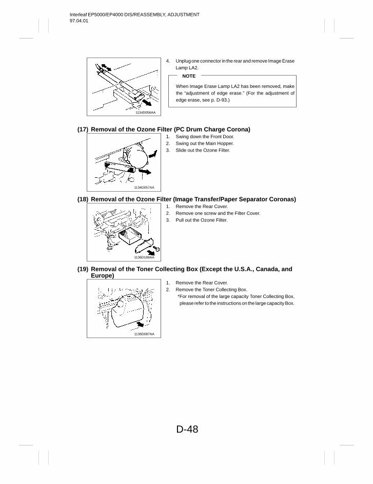
Interleaf EP5000/EP4000 DIS/REASSEMBLY, ADJUSTMENT97.04.01
D-48
1134D056AA
(17) Removal of the Ozone Filter (PC Drum Charge Corona)
1134D057AA
(18) Removal of the Ozone Filter (Image Transfer/Paper Separator Coronas)
1136D189AA
(19) Removal of the Toner Collecting Box (Except the U.S.A., Canada, and Europe)
1136D087AA
4. Unplug one connector in the rear and remove Image EraseLamp LA2.
NOTE
When Image Erase Lamp LA2 has been removed, makethe “adjustment of edge erase.” (For the adjustment ofedge erase, see p. D-93.)
1. Swing down the Front Door.2. Swing out the Main Hopper.3. Slide out the Ozone Filter.
1. Remove the Rear Cover.2. Remove one screw and the Filter Cover.3. Pull out the Ozone Filter.
1. Remove the Rear Cover.2. Remove the Toner Collecting Box.
*For removal of the large capacity Toner Collecting Box,please refer to the instructions on the large capacity Box.
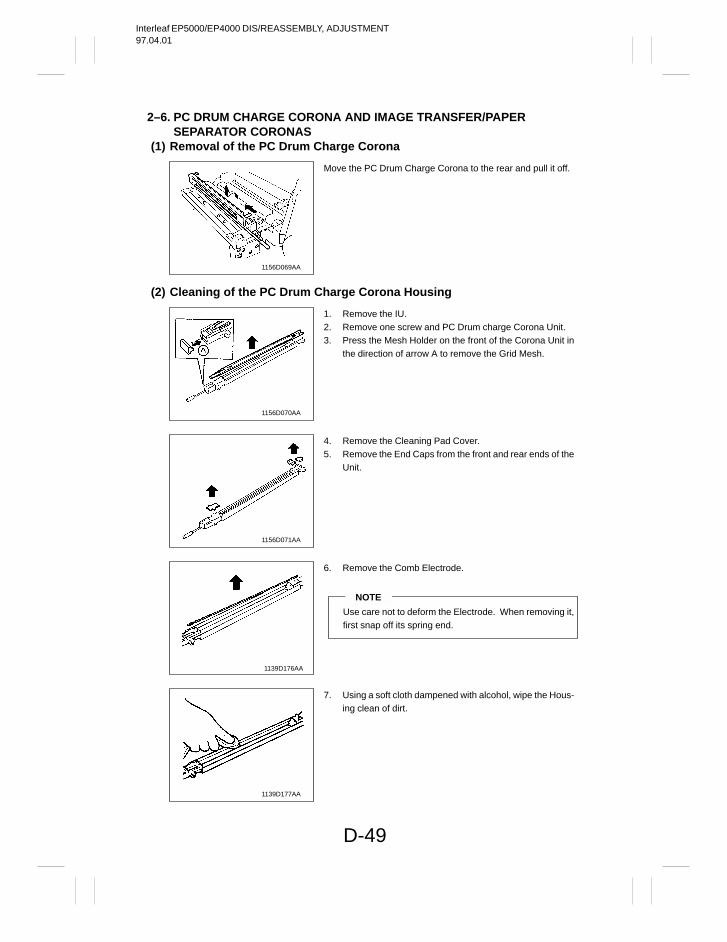
Interleaf EP5000/EP4000 DIS/REASSEMBLY, ADJUSTMENT97.04.01
D-49
2–6. PC DRUM CHARGE CORONA AND IMAGE TRANSFER/PAPER SEPARATOR CORONAS
(1) Removal of the PC Drum Charge Corona
1156D069AA
(2) Cleaning of the PC Drum Charge Corona Housing
1156D070AA
1156D071AA
1139D176AA
1139D177AA
Move the PC Drum Charge Corona to the rear and pull it off.
1. Remove the IU.2. Remove one screw and PC Drum charge Corona Unit.3. Press the Mesh Holder on the front of the Corona Unit in
the direction of arrow A to remove the Grid Mesh.
4. Remove the Cleaning Pad Cover.5. Remove the End Caps from the front and rear ends of the
Unit.
6. Remove the Comb Electrode.
NOTE
Use care not to deform the Electrode. When removing it,first snap off its spring end.
7. Using a soft cloth dampened with alcohol, wipe the Hous-ing clean of dirt.
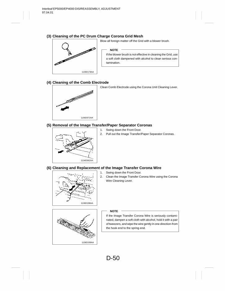
Interleaf EP5000/EP4000 DIS/REASSEMBLY, ADJUSTMENT97.04.01
D-50
(3) Cleaning of the PC Drum Charge Corona Grid Mesh
1139D178AA
(4) Cleaning of the Comb Electrode
1156D072AA
(5) Removal of the Image Transfer/Paper Separator Coronas
1134D062AA
(6) Cleaning and Replacement of the Image Transfer Corona Wire
1136D198AA
1136D199AA
Blow all foreign matter off the Grid with a blower brush.
NOTE
If the blower brush is not effective in cleaning the Grid, usea soft cloth dampened with alcohol to clean serious con-tamination.
Clean Comb Electrode using the Corona Unit Cleaning Lever.
1. Swing down the Front Door.2. Pull out the Image Transfer/Paper Separator Coronas.
1. Swing down the Front Door.2. Clean the Image Transfer Corona Wire using the Corona
Wire Cleaning Lever.
NOTE
If the Image Transfer Corona Wire is seriously contami-nated, dampen a soft cloth with alcohol, hold it with a pairof tweezers, and wipe the wire gently in one direction-fromthe hook end to the spring end.
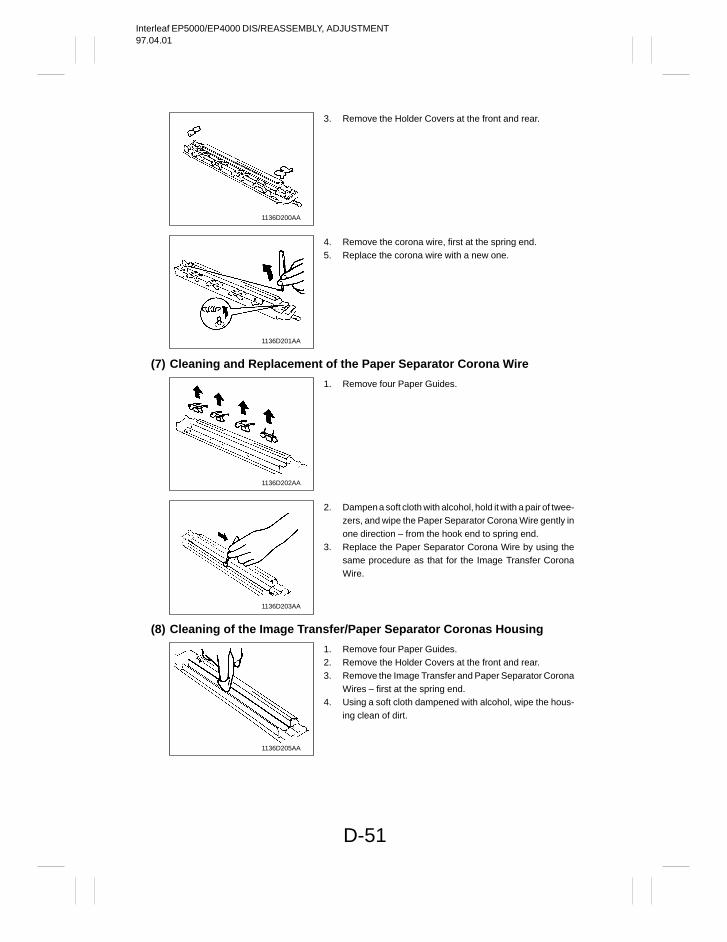
Interleaf EP5000/EP4000 DIS/REASSEMBLY, ADJUSTMENT97.04.01
D-51
1136D200AA
1136D201AA
(7) Cleaning and Replacement of the Paper Separator Corona Wire
1136D202AA
1136D203AA
(8) Cleaning of the Image Transfer/Paper Separator Coronas Housing
1136D205AA
3. Remove the Holder Covers at the front and rear.
4. Remove the corona wire, first at the spring end.5. Replace the corona wire with a new one.
1. Remove four Paper Guides.
2. Dampen a soft cloth with alcohol, hold it with a pair of twee-zers, and wipe the Paper Separator Corona Wire gently inone direction – from the hook end to spring end.
3. Replace the Paper Separator Corona Wire by using thesame procedure as that for the Image Transfer CoronaWire.
1. Remove four Paper Guides.2. Remove the Holder Covers at the front and rear.3. Remove the Image Transfer and Paper Separator Corona
Wires – first at the spring end.4. Using a soft cloth dampened with alcohol, wipe the hous-
ing clean of dirt.
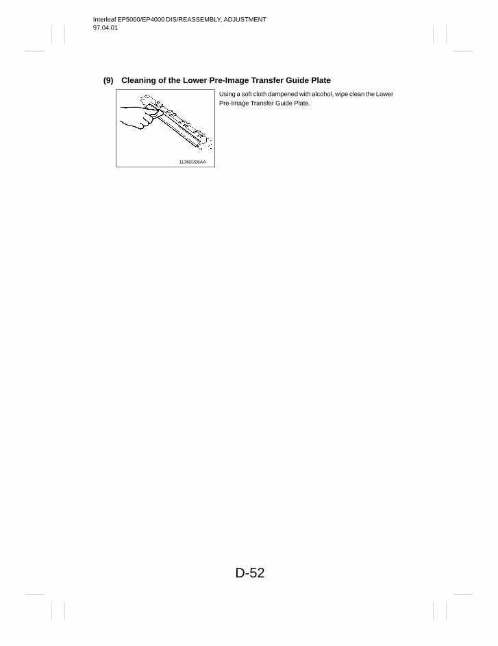
Interleaf EP5000/EP4000 DIS/REASSEMBLY, ADJUSTMENT97.04.01
D-52
(9) Cleaning of the Lower Pre-Image Transfer Guide Plate
1136D206AA
Using a soft cloth dampened with alcohol, wipe clean the LowerPre-Image Transfer Guide Plate.
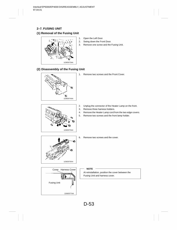
Interleaf EP5000/EP4000 DIS/REASSEMBLY, ADJUSTMENT97.04.01
D-53
2–7. FUSING UNIT
(1) Removal of the Fusing Unit
1156D073AA
(2) Disassembly of the Fusing Unit
1156D074AA
1156D075AA
1156D076AA
1156D077AA
Cover Harness Cover
Fusing Unit
1. Open the Left Door.2. Swing down the Front Door.3. Remove one screw and the Fusing Unit.
1. Remove two screws and the Front Cover.
2. Unplug the connector of the Heater Lamp on the front.3. Remove three harness holders.4. Remove the Heater Lamp cord from the two edge covers.5. Remove two screws and the front lamp holder.
6. Remove two screws and the cover.
NOTE
At reinstallation, position the cover between the Fusing Unit and harness cover.
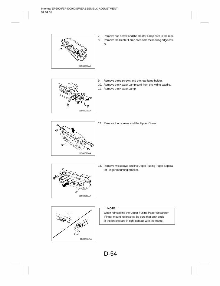
Interleaf EP5000/EP4000 DIS/REASSEMBLY, ADJUSTMENT97.04.01
D-54
1156D078AA
1156D079AA
1156D080AA
1156D081AA
1136D213AA
7. Remove one screw and the Heater Lamp cord in the rear.8. Remove the Heater Lamp cord from the locking edge cov-
er.
9. Remove three screws and the rear lamp holder.10. Remove the Heater Lamp cord from the wiring saddle.11. Remove the Heater Lamp.
12. Remove four screws and the Upper Cover.
13. Remove two screws and the Upper Fusing Paper Separa-tor Finger mounting bracket.
NOTE
When reinstalling the Upper Fusing Paper Separator Finger mounting bracket, be sure that both ends of the bracket are in tight contact with the frame.
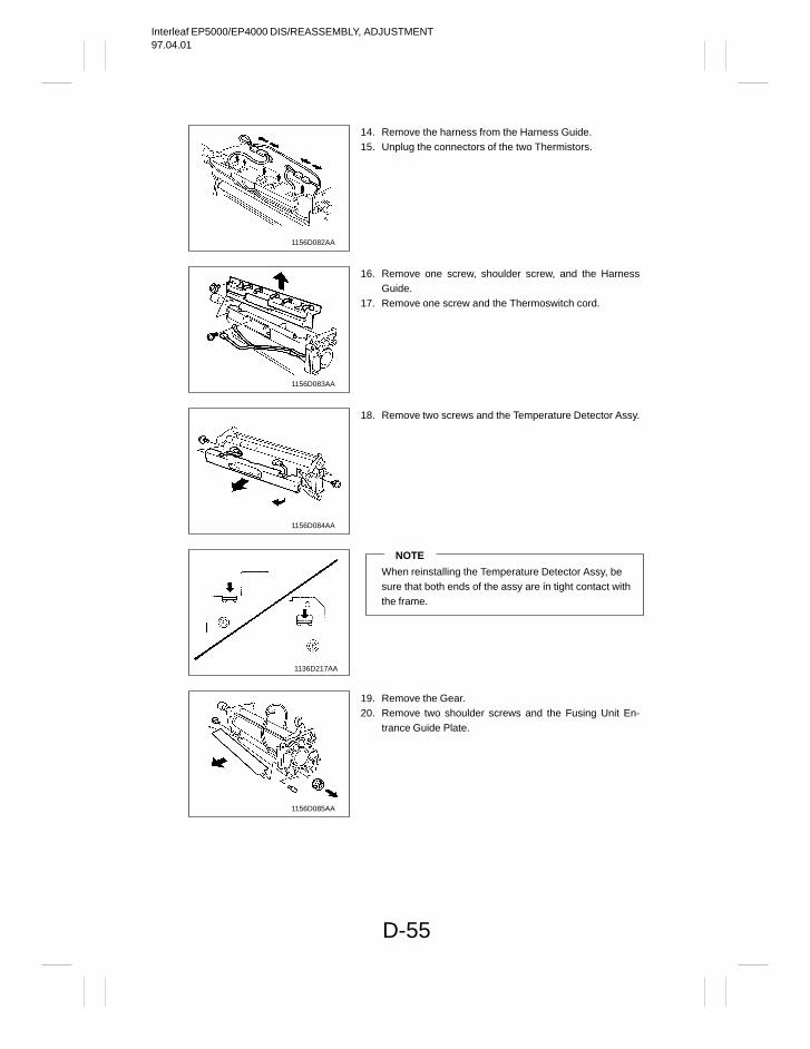
Interleaf EP5000/EP4000 DIS/REASSEMBLY, ADJUSTMENT97.04.01
D-55
1156D082AA
1156D083AA
1156D084AA
1136D217AA
1156D085AA
14. Remove the harness from the Harness Guide.15. Unplug the connectors of the two Thermistors.
16. Remove one screw, shoulder screw, and the HarnessGuide.
17. Remove one screw and the Thermoswitch cord.
18. Remove two screws and the Temperature Detector Assy.
NOTE
When reinstalling the Temperature Detector Assy, besure that both ends of the assy are in tight contact withthe frame.
19. Remove the Gear.20. Remove two shoulder screws and the Fusing Unit En-
trance Guide Plate.
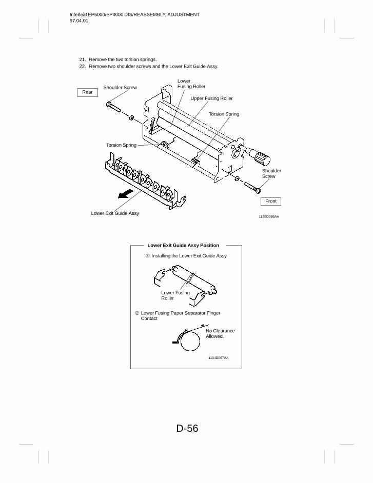
Interleaf EP5000/EP4000 DIS/REASSEMBLY, ADJUSTMENT97.04.01
D-56
21. Remove the two torsion springs.22. Remove two shoulder screws and the Lower Exit Guide Assy.
LowerFusing Roller
Upper Fusing Roller
Torsion Spring
ShoulderScrew
Shoulder Screw
Torsion Spring
Lower Exit Guide Assy1156D086AA
Front
Rear
Lower Exit Guide Assy Position
Installing the Lower Exit Guide Assy
Lower Fusing Paper Separator FingerContact
Lower FusingRoller
No ClearanceAllowed.
1134D067AA
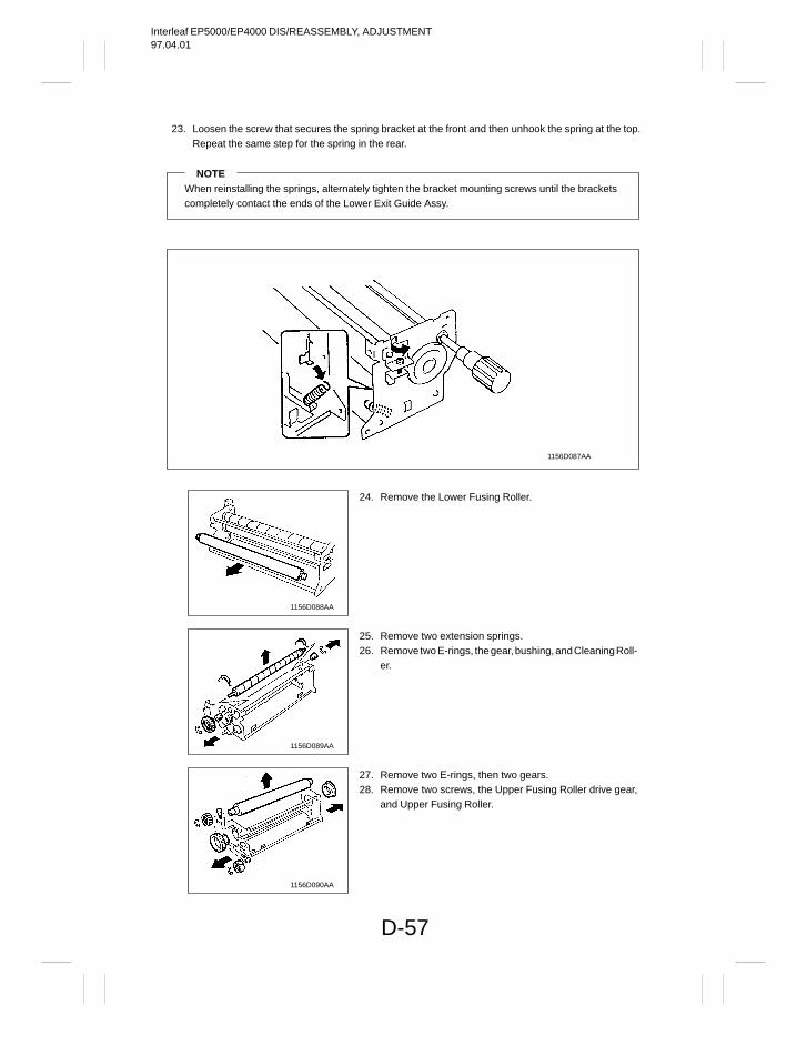
Interleaf EP5000/EP4000 DIS/REASSEMBLY, ADJUSTMENT97.04.01
D-57
23. Loosen the screw that secures the spring bracket at the front and then unhook the spring at the top.Repeat the same step for the spring in the rear.
NOTEWhen reinstalling the springs, alternately tighten the bracket mounting screws until the brackets completely contact the ends of the Lower Exit Guide Assy.
1156D087AA
1156D088AA
1156D089AA
1156D090AA
24. Remove the Lower Fusing Roller.
25. Remove two extension springs.26. Remove two E-rings, the gear, bushing, and Cleaning Roll-
er.
27. Remove two E-rings, then two gears.28. Remove two screws, the Upper Fusing Roller drive gear,
and Upper Fusing Roller.
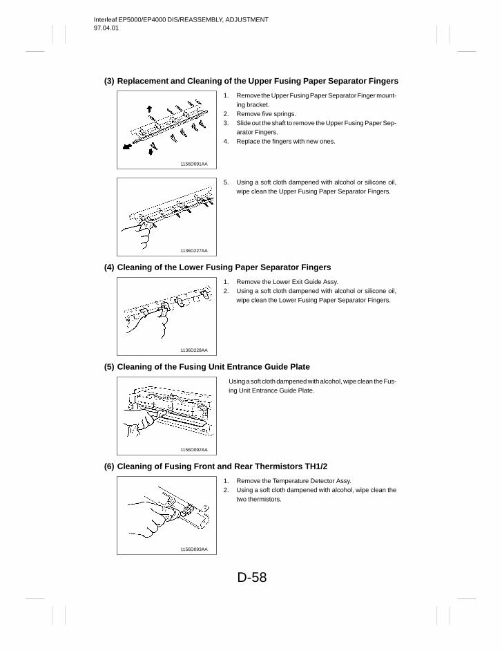
Interleaf EP5000/EP4000 DIS/REASSEMBLY, ADJUSTMENT97.04.01
D-58
(3) Replacement and Cleaning of the Upper Fusing Paper Separator Fingers
1156D091AA
1136D227AA
(4) Cleaning of the Lower Fusing Paper Separator Fingers
1136D228AA
(5) Cleaning of the Fusing Unit Entrance Guide Plate
1156D092AA
(6) Cleaning of Fusing Front and Rear Thermistors TH1/2
1156D093AA
1. Remove the Upper Fusing Paper Separator Finger mount-ing bracket.
2. Remove five springs.3. Slide out the shaft to remove the Upper Fusing Paper Sep-
arator Fingers.4. Replace the fingers with new ones.
5. Using a soft cloth dampened with alcohol or silicone oil,wipe clean the Upper Fusing Paper Separator Fingers.
1. Remove the Lower Exit Guide Assy.2. Using a soft cloth dampened with alcohol or silicone oil,
wipe clean the Lower Fusing Paper Separator Fingers.
Using a soft cloth dampened with alcohol, wipe clean the Fus-ing Unit Entrance Guide Plate.
1. Remove the Temperature Detector Assy.2. Using a soft cloth dampened with alcohol, wipe clean the
two thermistors.
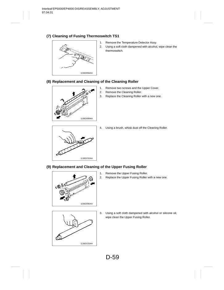
Interleaf EP5000/EP4000 DIS/REASSEMBLY, ADJUSTMENT97.04.01
D-59
(7) Cleaning of Fusing Thermoswitch TS1
1156D094AA
(8) Replacement and Cleaning of the Cleaning Roller
1156D089AA
1136D232AA
(9) Replacement and Cleaning of the Upper Fusing Roller
1156D090AA
1136D233AA
1. Remove the Temperature Detector Assy.2. Using a soft cloth dampened with alcohol, wipe clean the
thermoswitch.
1. Remove two screws and the Upper Cover.2. Remove the Cleaning Roller.3. Replace the Cleaning Roller with a new one.
4. Using a brush, whisk dust off the Cleaning Roller.
1. Remove the Upper Fusing Roller.2. Replace the Upper Fusing Roller with a new one.
3. Using a soft cloth dampened with alcohol or silicone oil,wipe clean the Upper Fusing Roller.
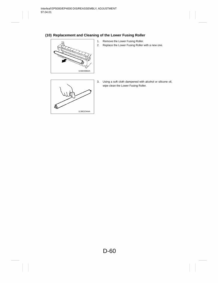
Interleaf EP5000/EP4000 DIS/REASSEMBLY, ADJUSTMENT97.04.01
D-60
(10) Replacement and Cleaning of the Lower Fusing Roller
1156D088AA
1136D234AA
1. Remove the Lower Fusing Roller.2. Replace the Lower Fusing Roller with a new one.
3. Using a soft cloth dampened with alcohol or silicone oil,wipe clean the Lower Fusing Roller.
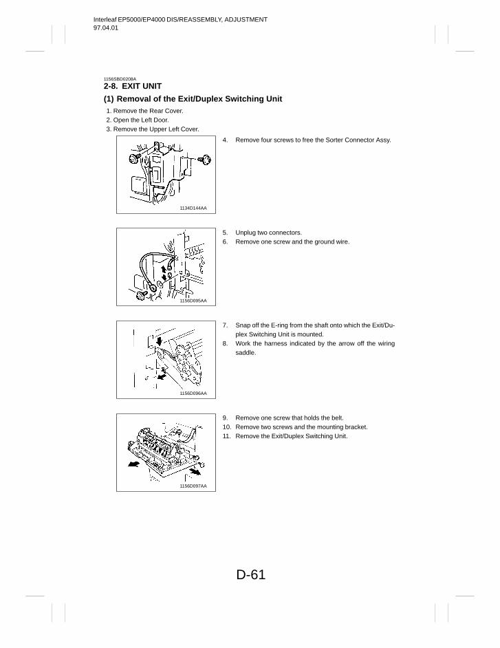
Interleaf EP5000/EP4000 DIS/REASSEMBLY, ADJUSTMENT97.04.01
D-61
1156SBD0208A
2-8. EXIT UNIT
(1) Removal of the Exit/Duplex Switching Unit1. Remove the Rear Cover.2. Open the Left Door.3. Remove the Upper Left Cover.
1134D144AA
1156D095AA
1156D096AA
1156D097AA
4. Remove four screws to free the Sorter Connector Assy.
5. Unplug two connectors.6. Remove one screw and the ground wire.
7. Snap off the E-ring from the shaft onto which the Exit/Du-plex Switching Unit is mounted.
8. Work the harness indicated by the arrow off the wiringsaddle.
9. Remove one screw that holds the belt.10. Remove two screws and the mounting bracket.11. Remove the Exit/Duplex Switching Unit.
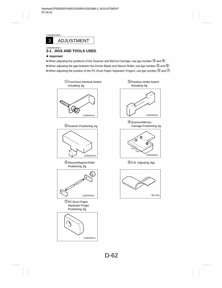
Interleaf EP5000/EP4000 DIS/REASSEMBLY, ADJUSTMENT97.04.01
D-62
1156SBD0300A
ADJUSTMENT31156SBD0301A
3-1. JIGS AND TOOLS USED Important
When adjusting the positions of the Scanner and Mirrors Carriage, use jigs number and .
When adjusting the gap between the Doctor Blade and Sleeve Roller, use jigs number and .
When adjusting the position of the PC Drum Paper Separator Fingers, use jigs number and .
Front Door Interlock SwitchActuating Jig
Predrive Inhibit SwitchActuating Jig
Scanner Positioning JigScanner/Mirrors
Carriage Positioning Jig
Sleeve/Magnet RollerPositioning Jig
D.B. Adjusting Jigs
PC Drum PaperSeparator FingerPositioning Jig
1136D006AA
1136D003AA
1136D002AA
1136D005AA1136D001AA
1136D004AA
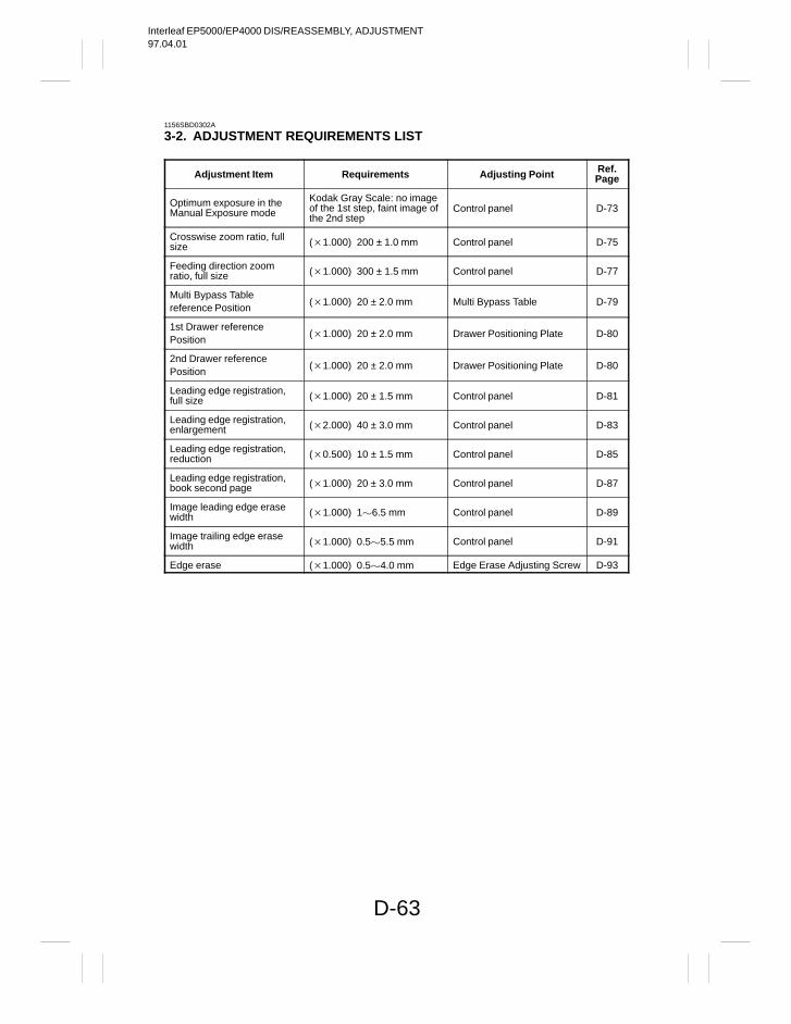
Interleaf EP5000/EP4000 DIS/REASSEMBLY, ADJUSTMENT97.04.01
D-63
1156SBD0302A
3-2. ADJUSTMENT REQUIREMENTS LIST
Adjustment Item Requirements Adjusting Point Ref.Page
Optimum exposure in theManual Exposure mode
Kodak Gray Scale: no imageof the 1st step, faint image ofthe 2nd step
Control panel D-73
Crosswise zoom ratio, fullsize (1.000) 200 ± 1.0 mm Control panel D-75
Feeding direction zoom ratio, full size (1.000) 300 ± 1.5 mm Control panel D-77
Multi Bypass Tablereference Position
(1.000) 20 ± 2.0 mm Multi Bypass Table D-79
1st Drawer referencePosition
(1.000) 20 ± 2.0 mm Drawer Positioning Plate D-80
2nd Drawer referencePosition
(1.000) 20 ± 2.0 mm Drawer Positioning Plate D-80
Leading edge registration,full size (1.000) 20 ± 1.5 mm Control panel D-81
Leading edge registration,enlargement (2.000) 40 ± 3.0 mm Control panel D-83
Leading edge registration,reduction (0.500) 10 ± 1.5 mm Control panel D-85
Leading edge registration,book second page (1.000) 20 ± 3.0 mm Control panel D-87
Image leading edge erasewidth (1.000) 16.5 mm Control panel D-89
Image trailing edge erasewidth (1.000) 0.55.5 mm Control panel D-91
Edge erase (1.000) 0.54.0 mm Edge Erase Adjusting Screw D-93
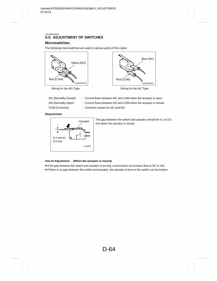
Interleaf EP5000/EP4000 DIS/REASSEMBLY, ADJUSTMENT97.04.01
D-64
1151SBD0303A
3-3. ADJUSTMENT OF SWITCHES
MicroswitchesThe following microswitches are used in various parts of this copier.
Wiring for the NO Type Wiring for the NC Type
NC (Normally-Closed) : Current flows between NC and COM when the actuator is open.
NO (Normally-Open) : Current flows between NO and COM when the actuator is closed.
COM (Common) : Common contact for NC and NO.
Yellow (NO)
Red (COM)
Blue (NC)
Red (COM)1136D007AA 1136D008AA
Requirement
0.1 mm to0.5 mm
Actuator
Out-of-Adjustment (When the actuator is closed)
If the gap between the switch and actuator is too big, current does not at times flow to NC or NO. If there is no gap between the switch and actuator, the actuator is bent or the switch can be broken.
The gap between the switch and actuator should be 0.1 to 0.5mm when the actuator is closed.
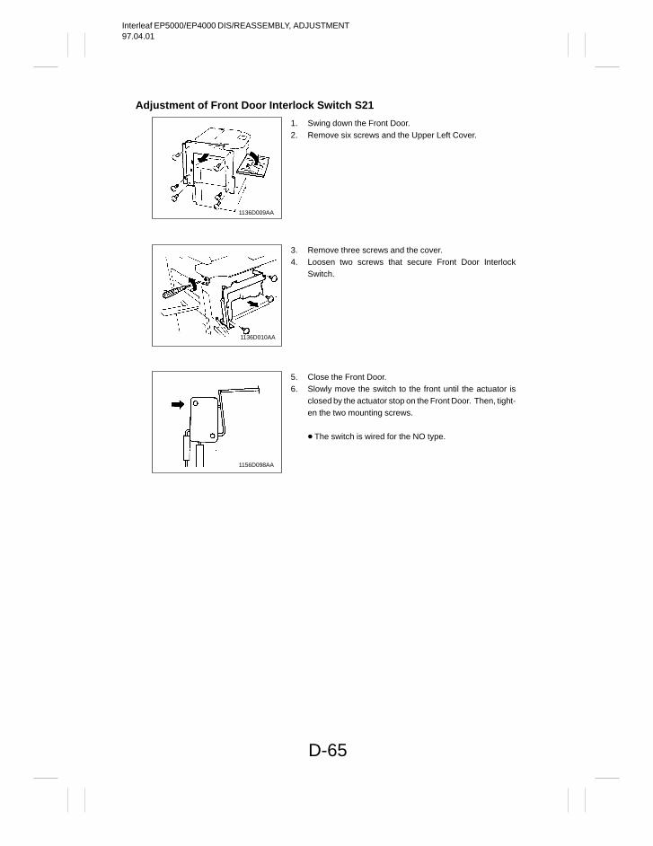
Interleaf EP5000/EP4000 DIS/REASSEMBLY, ADJUSTMENT97.04.01
D-65
Adjustment of Front Door Interlock Switch S21
1136D009AA
1136D010AA
1156D098AA
1. Swing down the Front Door.2. Remove six screws and the Upper Left Cover.
3. Remove three screws and the cover.4. Loosen two screws that secure Front Door Interlock
Switch.
5. Close the Front Door.6. Slowly move the switch to the front until the actuator is
closed by the actuator stop on the Front Door. Then, tight-en the two mounting screws.
The switch is wired for the NO type.
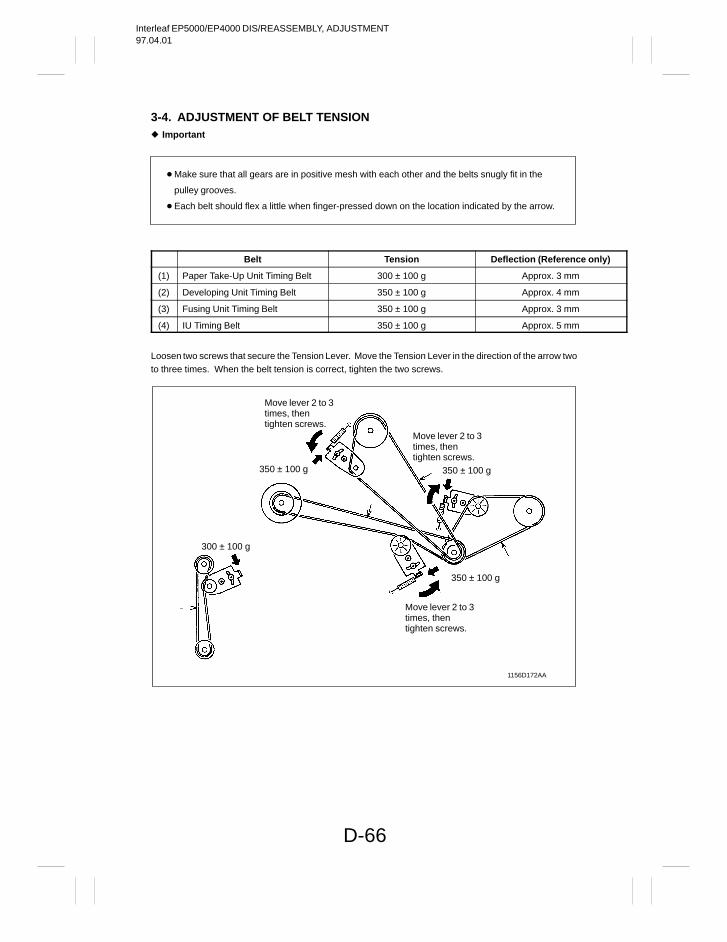
Interleaf EP5000/EP4000 DIS/REASSEMBLY, ADJUSTMENT97.04.01
D-66
3-4. ADJUSTMENT OF BELT TENSION Important
Make sure that all gears are in positive mesh with each other and the belts snugly fit in the
pulley grooves.
Each belt should flex a little when finger-pressed down on the location indicated by the arrow.
Belt Tension Deflection (Reference only)
(1) Paper Take-Up Unit Timing Belt 300 ± 100 g Approx. 3 mm
(2) Developing Unit Timing Belt 350 ± 100 g Approx. 4 mm
(3) Fusing Unit Timing Belt 350 ± 100 g Approx. 3 mm
(4) IU Timing Belt 350 ± 100 g Approx. 5 mm
Loosen two screws that secure the Tension Lever. Move the Tension Lever in the direction of the arrow twoto three times. When the belt tension is correct, tighten the two screws.
1156D172AA
350 ± 100 g
300 ± 100 g
350 ± 100 g
350 ± 100 g
Move lever 2 to 3times, thentighten screws.
Move lever 2 to 3times, thentighten screws.
Move lever 2 to 3times, thentighten screws.
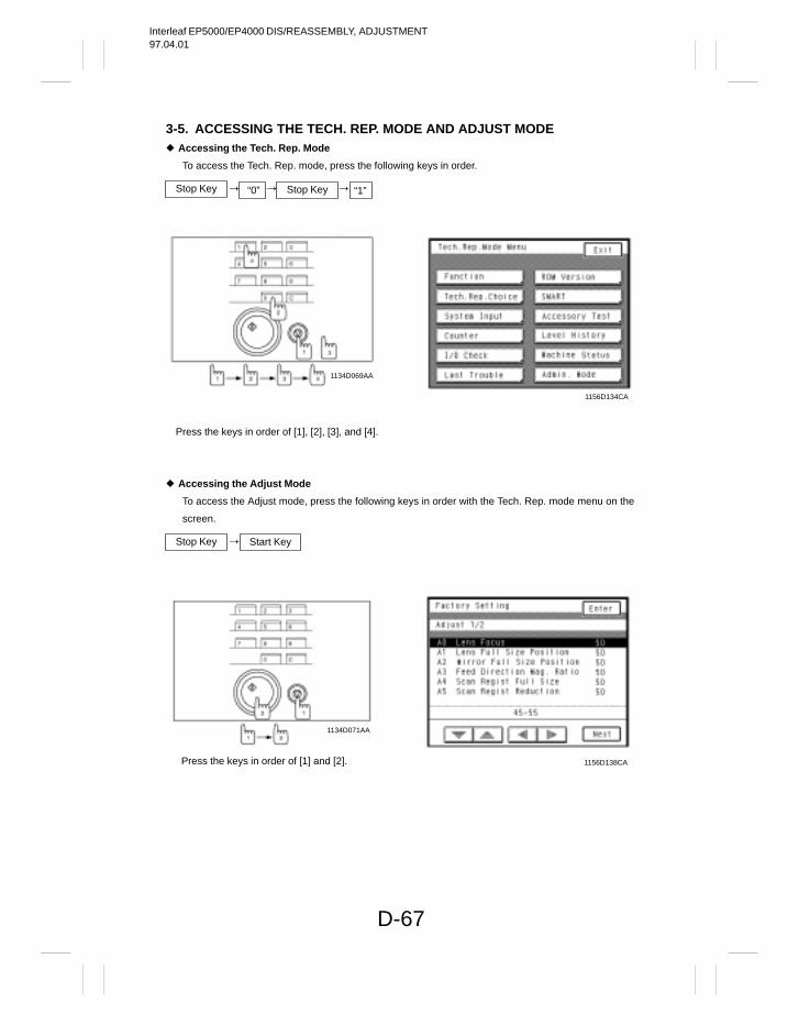
Interleaf EP5000/EP4000 DIS/REASSEMBLY, ADJUSTMENT97.04.01
D-67
3-5. ACCESSING THE TECH. REP. MODE AND ADJUST MODE Accessing the Tech. Rep. Mode
To access the Tech. Rep. mode, press the following keys in order.
Stop Key Stop Key“0” “1”
1156D134CA
Press the keys in order of [1], [2], [3], and [4].
1134D069AA
Accessing the Adjust Mode
To access the Adjust mode, press the following keys in order with the Tech. Rep. mode menu on the
screen.
Stop Key Start Key
1156D138CAPress the keys in order of [1] and [2].
1134D071AA
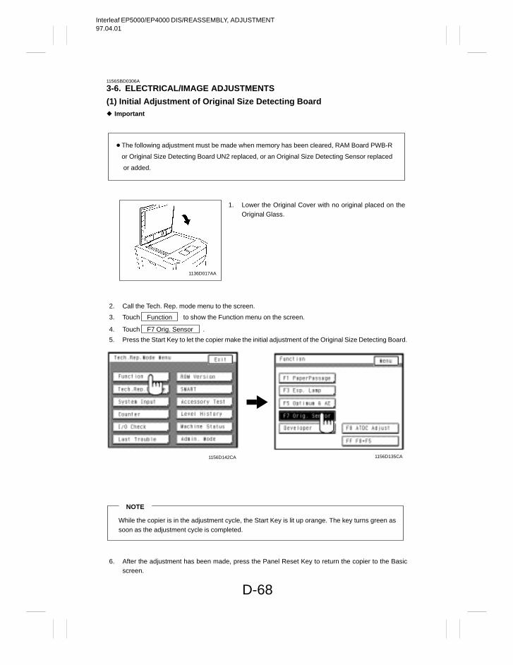
Interleaf EP5000/EP4000 DIS/REASSEMBLY, ADJUSTMENT97.04.01
D-68
1156SBD0306A
3-6. ELECTRICAL/IMAGE ADJUSTMENTS
(1) Initial Adjustment of Original Size Detecting Board Important
The following adjustment must be made when memory has been cleared, RAM Board PWB-R
or Original Size Detecting Board UN2 replaced, or an Original Size Detecting Sensor replaced
or added.
1136D017AA
2. Call the Tech. Rep. mode menu to the screen.
3. Touch Function to show the Function menu on the screen.
4. Touch F7 Orig. Sensor .
5. Press the Start Key to let the copier make the initial adjustment of the Original Size Detecting Board.
1156D142CA 1156D135CA
NOTE
While the copier is in the adjustment cycle, the Start Key is lit up orange. The key turns green as soon as the adjustment cycle is completed.
6. After the adjustment has been made, press the Panel Reset Key to return the copier to the Basicscreen.
1. Lower the Original Cover with no original placed on theOriginal Glass.
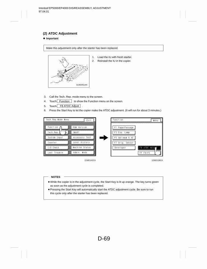
Interleaf EP5000/EP4000 DIS/REASSEMBLY, ADJUSTMENT97.04.01
D-69
(2) ATDC Adjustment Important
Make this adjustment only after the starter has been replaced.
1134D051AA
3. Call the Tech. Rep. mode menu to the screen.
4. Touch Function to show the Function menu on the screen.
5. Touch F8 ATDC Adjust .
6. Press the Start Key to let the copier make the ATDC adjustment. (It will run for about 3 minutes.)
1156D142CA 1156D139CA
NOTES
While the copier is in the adjustment cycle, the Start Key is lit up orange. The key turns greenas soon as the adjustment cycle is completed.
Pressing the Start Key will automatically start the ATDC adjustment cycle. Be sure to run this cycle only after the starter has been replaced.
1. Load the IU with fresh starter.2. Reinstall the IU in the copier.
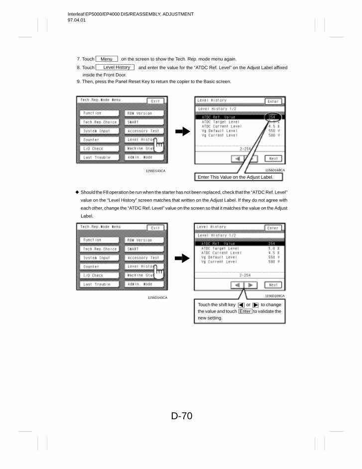
Interleaf EP5000/EP4000 DIS/REASSEMBLY, ADJUSTMENT97.04.01
D-70
7. Touch Menu on the screen to show the Tech. Rep. mode menu again.
8. Touch Level History and enter the value for the “ATDC Ref. Level” on the Adjust Label affixed
inside the Front Door.9. Then, press the Panel Reset Key to return the copier to the Basic screen.
1156D143CA 1156D168CA
Enter This Value on the Adjust Label.
Should the F8 operation be run when the starter has not been replaced, check that the “ATDC Ref. Level”
value on the “Level History” screen matches that written on the Adjust Label. If they do not agree with
each other, change the “ATDC Ref. Level” value on the screen so that it matches the value on the Adjust
Label.
1156D143CA
Touch the shift key or to changethe value and touch Enter to validate thenew setting.
1156D169CA
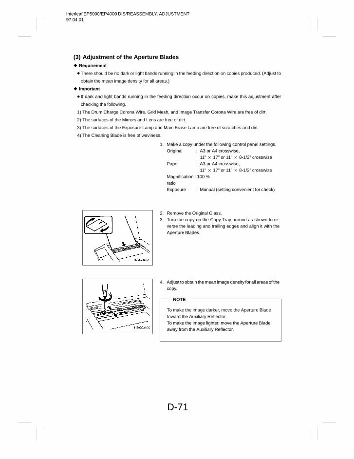
Interleaf EP5000/EP4000 DIS/REASSEMBLY, ADJUSTMENT97.04.01
D-71
(3) Adjustment of the Aperture Blades Requirement
There should be no dark or light bands running in the feeding direction on copies produced. (Adjust to
obtain the mean image density for all areas.)
Important
If dark and light bands running in the feeding direction occur on copies, make this adjustment after
checking the following.
1) The Drum Charge Corona Wire, Grid Mesh, and Image Transfer Corona Wire are free of dirt.
2) The surfaces of the Mirrors and Lens are free of dirt.
3) The surfaces of the Exposure Lamp and Main Erase Lamp are free of scratches and dirt.
4) The Cleaning Blade is free of waviness.
1. Make a copy under the following control panel settings.Original : A3 or A4 crosswise,
11” 17” or 11” 8-1/2” crosswisePaper : A3 or A4 crosswise,
11” 17” or 11” 8-1/2” crosswiseMagnification : 100 %ratioExposure : Manual (setting convenient for check)
2. Remove the Original Glass.3. Turn the copy on the Copy Tray around as shown to re-
verse the leading and trailing edges and align it with theAperture Blades.
4. Adjust to obtain the mean image density for all areas of thecopy.
NOTE
To make the image darker, move the Aperture Bladetoward the Auxiliary Reflector.To make the image lighter, move the Aperture Bladeaway from the Auxiliary Reflector.
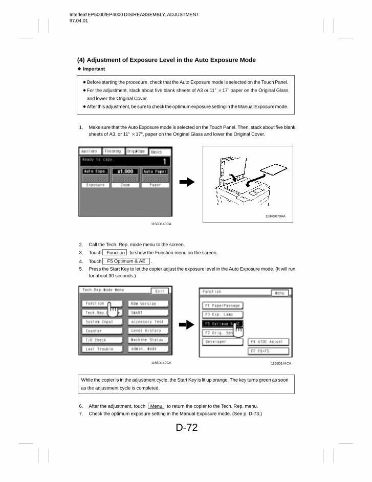
Interleaf EP5000/EP4000 DIS/REASSEMBLY, ADJUSTMENT97.04.01
D-72
(4) Adjustment of Exposure Level in the Auto Exposure Mode Important
Before starting the procedure, check that the Auto Exposure mode is selected on the Touch Panel.
For the adjustment, stack about five blank sheets of A3 or 11” 17” paper on the Original Glass
and lower the Original Cover.
After this adjustment, be sure to check the optimum exposure setting in the Manual Exposure mode.
1. Make sure that the Auto Exposure mode is selected on the Touch Panel. Then, stack about five blanksheets of A3, or 11” 17”, paper on the Original Glass and lower the Original Cover.
1134D079AA
1156D140CA
2. Call the Tech. Rep. mode menu to the screen.
3. Touch Function to show the Function menu on the screen.
4. Touch F5 Optimum & AE .
5. Press the Start Key to let the copier adjust the exposure level in the Auto Exposure mode. (It will runfor about 30 seconds.)
1156D142CA 1156D144CA
While the copier is in the adjustment cycle, the Start Key is lit up orange. The key turns green as soon
as the adjustment cycle is completed.
6. After the adjustment, touch Menu to return the copier to the Tech. Rep. menu.
7. Check the optimum exposure setting in the Manual Exposure mode. (See p. D-73.)
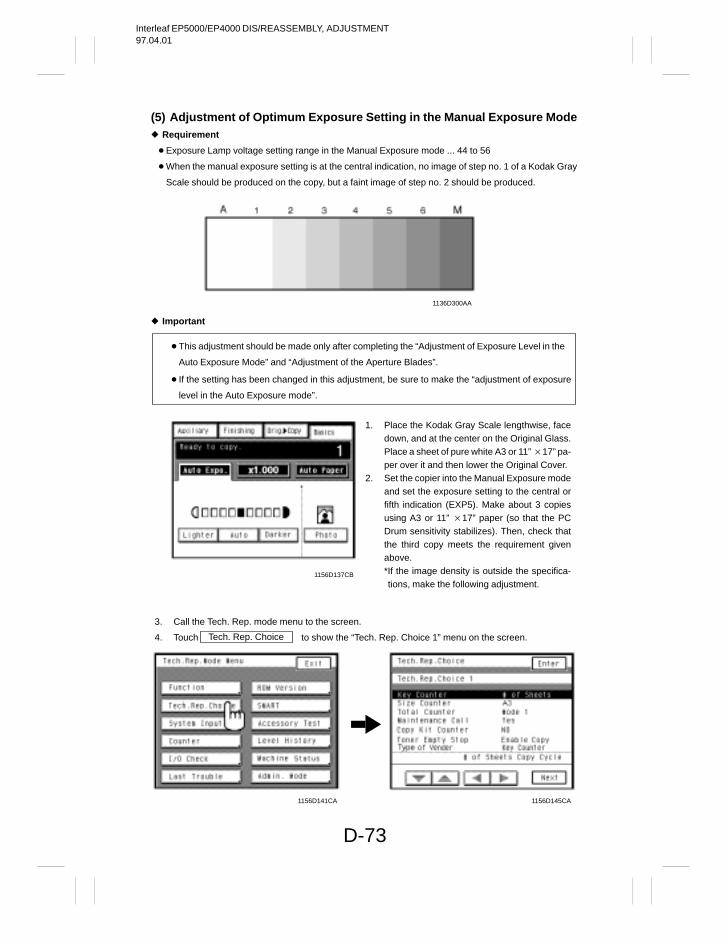
Interleaf EP5000/EP4000 DIS/REASSEMBLY, ADJUSTMENT97.04.01
D-73
(5) Adjustment of Optimum Exposure Setting in the Manual Exposure Mode Requirement
Exposure Lamp voltage setting range in the Manual Exposure mode ... 44 to 56
When the manual exposure setting is at the central indication, no image of step no. 1 of a Kodak Gray
Scale should be produced on the copy, but a faint image of step no. 2 should be produced.
1136D300AA
Important
This adjustment should be made only after completing the “Adjustment of Exposure Level in the
Auto Exposure Mode” and “Adjustment of the Aperture Blades”.
If the setting has been changed in this adjustment, be sure to make the “adjustment of exposure
level in the Auto Exposure mode”.
1156D137CB
3. Call the Tech. Rep. mode menu to the screen.
4. Touch Tech. Rep. Choice to show the “Tech. Rep. Choice 1” menu on the screen.
1156D141CA 1156D145CA
1. Place the Kodak Gray Scale lengthwise, facedown, and at the center on the Original Glass.Place a sheet of pure white A3 or 11” 17” pa-per over it and then lower the Original Cover.
2. Set the copier into the Manual Exposure modeand set the exposure setting to the central orfifth indication (EXP5). Make about 3 copiesusing A3 or 11” 17” paper (so that the PCDrum sensitivity stabilizes). Then, check thatthe third copy meets the requirement givenabove.*If the image density is outside the specifica-tions, make the following adjustment.
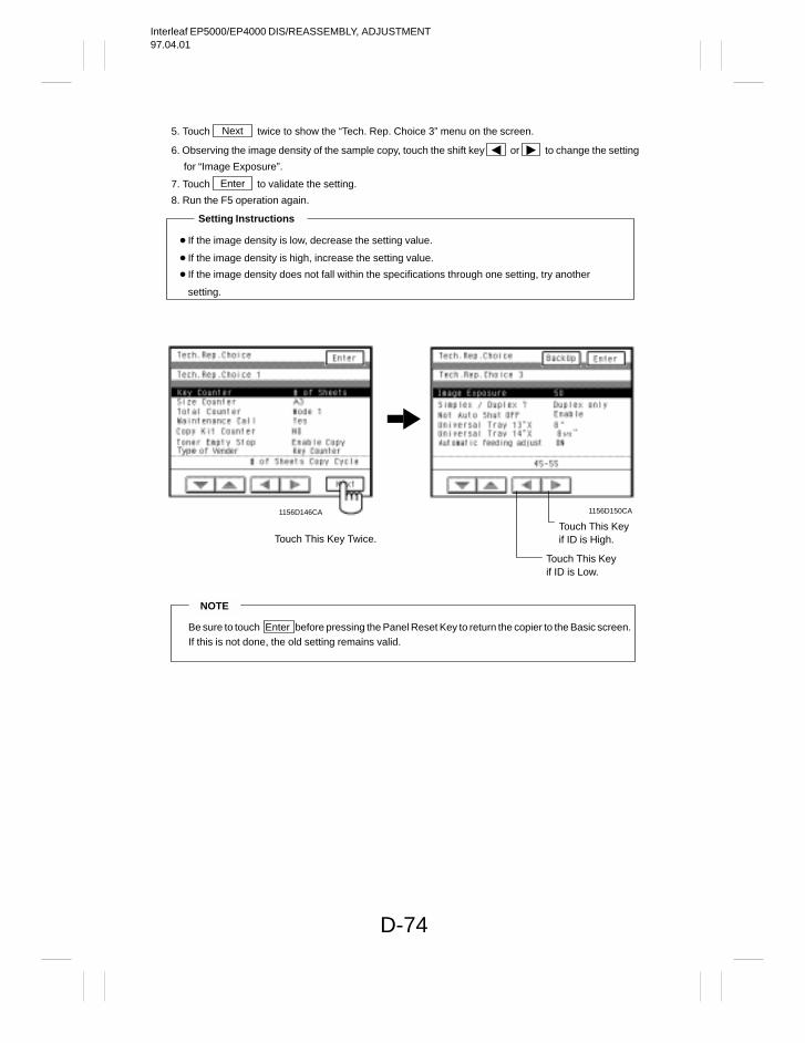
Interleaf EP5000/EP4000 DIS/REASSEMBLY, ADJUSTMENT97.04.01
D-74
5. Touch Next twice to show the “Tech. Rep. Choice 3” menu on the screen.
6. Observing the image density of the sample copy, touch the shift key or to change the setting
for “Image Exposure”.
7. Touch Enter to validate the setting.
8. Run the F5 operation again.
If the image density is low, decrease the setting value.
If the image density is high, increase the setting value.
If the image density does not fall within the specifications through one setting, try another
setting.
Setting Instructions
1156D150CA
Touch This Key Twice.Touch This Keyif ID is High.
Touch This Keyif ID is Low.
1156D146CA
NOTE
Be sure to touch Enter before pressing the Panel Reset Key to return the copier to the Basic screen.If this is not done, the old setting remains valid.
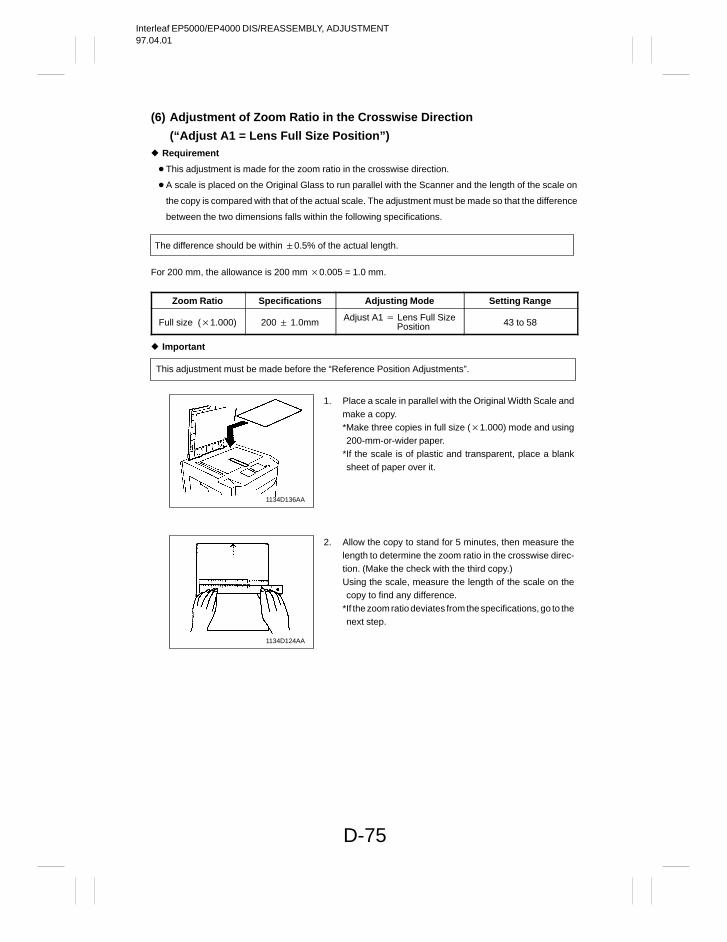
Interleaf EP5000/EP4000 DIS/REASSEMBLY, ADJUSTMENT97.04.01
D-75
(6) Adjustment of Zoom Ratio in the Crosswise Direction
(“Adjust A1 = Lens Full Size Position”) Requirement
This adjustment is made for the zoom ratio in the crosswise direction.
A scale is placed on the Original Glass to run parallel with the Scanner and the length of the scale on
the copy is compared with that of the actual scale. The adjustment must be made so that the difference
between the two dimensions falls within the following specifications.
The difference should be within 0.5% of the actual length.
For 200 mm, the allowance is 200 mm 0.005 = 1.0 mm.
Zoom Ratio Specifications Adjusting Mode Setting Range
Full size (1.000) 200 1.0mm Adjust A1 Lens Full Size Position 43 to 58
Important
This adjustment must be made before the “Reference Position Adjustments”.
1134D136AA
1134D124AA
1. Place a scale in parallel with the Original Width Scale andmake a copy.*Make three copies in full size (1.000) mode and using200-mm-or-wider paper.
*If the scale is of plastic and transparent, place a blanksheet of paper over it.
2. Allow the copy to stand for 5 minutes, then measure thelength to determine the zoom ratio in the crosswise direc-tion. (Make the check with the third copy.)Using the scale, measure the length of the scale on thecopy to find any difference.
*If the zoom ratio deviates from the specifications, go to thenext step.
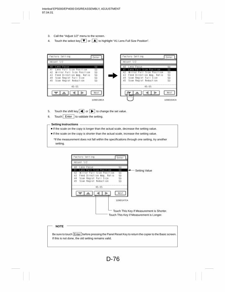
Interleaf EP5000/EP4000 DIS/REASSEMBLY, ADJUSTMENT97.04.01
D-76
3. Call the “Adjust 1/2” menu to the screen.
4. Touch the select key or to highlight “A1 Lens Full Size Position”.
1156D138CA 1156D154CA
5. Touch the shift key or to change the set value.
6. Touch Enter to validate the setting.
If the scale on the copy is longer than the actual scale, decrease the setting value.
If the scale on the copy is shorter than the actual scale, increase the setting value.
*If the measurement does not fall within the specifications through one setting, try anothersetting.
Setting Instructions
Touch This Key if Measurement is Shorter.Touch This Key if Measurement is Longer.
Setting Value
1156D147CA
NOTE
Be sure to touch Enter before pressing the Panel Reset Key to return the copier to the Basic screen.If this is not done, the old setting remains valid.
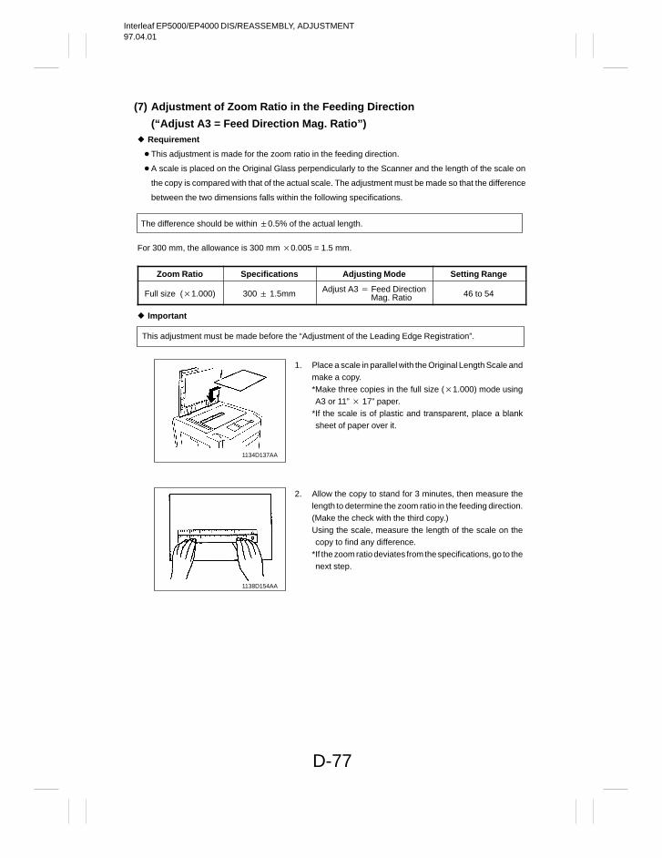
Interleaf EP5000/EP4000 DIS/REASSEMBLY, ADJUSTMENT97.04.01
D-77
(7) Adjustment of Zoom Ratio in the Feeding Direction
(“Adjust A3 = Feed Direction Mag. Ratio”) Requirement
This adjustment is made for the zoom ratio in the feeding direction.
A scale is placed on the Original Glass perpendicularly to the Scanner and the length of the scale on
the copy is compared with that of the actual scale. The adjustment must be made so that the difference
between the two dimensions falls within the following specifications.
The difference should be within 0.5% of the actual length.
For 300 mm, the allowance is 300 mm 0.005 = 1.5 mm.
Zoom Ratio Specifications Adjusting Mode Setting Range
Full size (1.000) 300 1.5mm Adjust A3 Feed Direction Mag. Ratio 46 to 54
Important
This adjustment must be made before the “Adjustment of the Leading Edge Registration”.
1134D137AA
1138D154AA
1. Place a scale in parallel with the Original Length Scale andmake a copy.*Make three copies in the full size (1.000) mode usingA3 or 11” 17” paper.
*If the scale is of plastic and transparent, place a blanksheet of paper over it.
2. Allow the copy to stand for 3 minutes, then measure thelength to determine the zoom ratio in the feeding direction.(Make the check with the third copy.)Using the scale, measure the length of the scale on thecopy to find any difference.
*If the zoom ratio deviates from the specifications, go to thenext step.
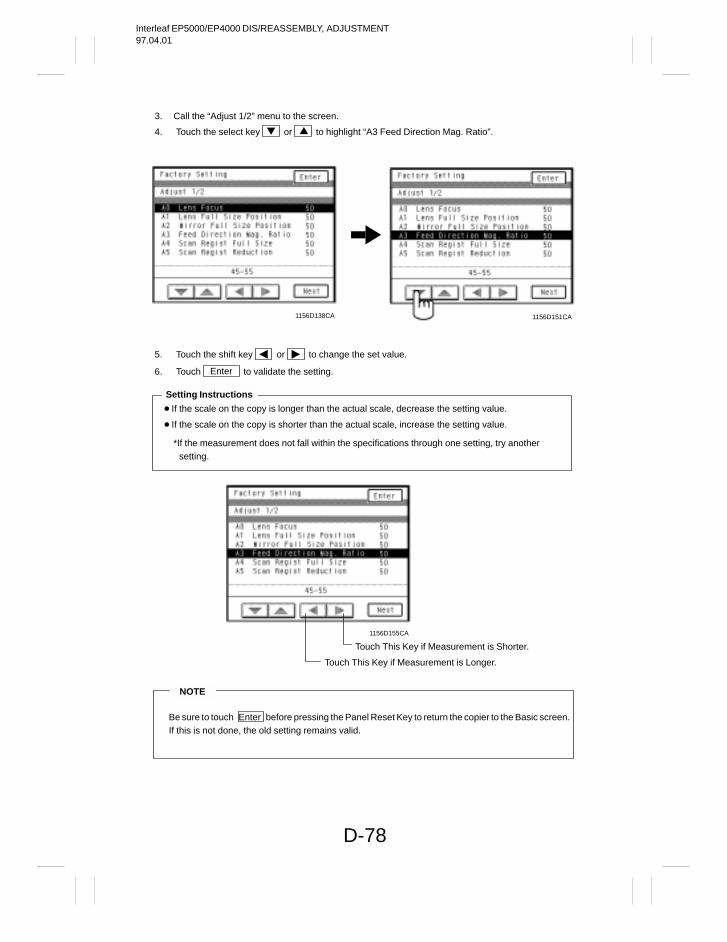
Interleaf EP5000/EP4000 DIS/REASSEMBLY, ADJUSTMENT97.04.01
D-78
3. Call the “Adjust 1/2” menu to the screen.
4. Touch the select key or to highlight “A3 Feed Direction Mag. Ratio”.
1156D138CA 1156D151CA
5. Touch the shift key or to change the set value.
6. Touch Enter to validate the setting.
If the scale on the copy is longer than the actual scale, decrease the setting value.
If the scale on the copy is shorter than the actual scale, increase the setting value.
*If the measurement does not fall within the specifications through one setting, try another setting.
Setting Instructions
Touch This Key if Measurement is Shorter.
Touch This Key if Measurement is Longer.
1156D155CA
NOTE
Be sure to touch Enter before pressing the Panel Reset Key to return the copier to the Basic screen.If this is not done, the old setting remains valid.
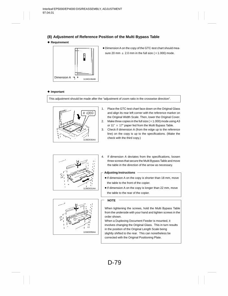
Interleaf EP5000/EP4000 DIS/REASSEMBLY, ADJUSTMENT97.04.01
D-79
(8) Adjustment of Reference Position of the Multi Bypass Table Requirement
Dimension A1134D196AB
Important
This adjustment should be made after the “adjustment of zoom ratio in the crosswise direction”.
1136D030AA
1136D031AA
1156D099AA
Dimension A on the copy of the GTC-test chart should mea-
sure 20 mm 2.0 mm in the full size (1.000) mode.
1. Place the GTC-test chart face down on the Original Glassand align its rear left corner with the reference marker onthe Original Width Scale. Then, lower the Original Cover.
2. Make three copies in the full size (1.000) mode using A3or 11” 17” paper fed from the Multi Bypass Table.
3. Check if dimension A (from the edge up to the referenceline) on the copy is up to the specifications. (Make thecheck with the third copy.)
4. If dimension A deviates from the specifications, loosenthree screws that secure the Multi Bypass Table and movethe table in the direction of the arrow as necessary.
If dimension A on the copy is shorter than 18 mm, move
the table to the front of the copier.
If dimension A on the copy is longer than 22 mm, move
the table to the rear of the copier.
Adjusting Instructions
NOTE
When tightening the screws, hold the Multi Bypass Tablefrom the underside with your hand and tighten screws in theorder shown.When a Duplexing Document Feeder is mounted, itinvolves changing the Original Glass. This in turn resultsin the position of the Original Length Scale beingslightly shifted to the rear. This can nonetheless becorrected with the Original Positioning Plate.
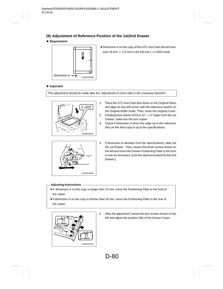
Interleaf EP5000/EP4000 DIS/REASSEMBLY, ADJUSTMENT97.04.01
D-80
(9) Adjustment of Reference Position of the 1st/2nd Drawer Requirement
1134D196ABDimension A
Important
This adjustment should be made after the “adjustment of zoom ratio in the crosswise direction”.
1136D030AA
1134D146AA
If dimension A on the copy is longer than 22 mm, move the Positioning Plate to the front of
the copier.
If dimension A on the copy is shorter than 18 mm, move the Positioning Plate to the rear of
the copier.
Adjusting Instructions
1139U037AA
Dimension A on the copy of the GTC-test chart should mea-
sure 20 mm 2.0 mm in the full size (1.000) mode.
1. Place the GTC-test chart face down on the Original Glassand align its rear left corner with the reference marker onthe Original Width Scale. Then, lower the Original Cover.
2. Feeding three sheets of A3 or 11” 17” paper from the 1stDrawer, make two full-size copies.
3. Check if dimension A (from the edge up to the referenceline) on the third copy is up to the specifications.
4. If dimension A deviates from the specifications, slide outthe 1st Drawer. Then, loosen the three screws shown onthe left and move the Drawer Positioning Plate to the frontor rear as necessary. (Use the same procedure for the 2ndDrawer.)
5. After the adjustment, loosen the four screws shown on theleft and adjust the position (tilt) of the Drawer Cover.
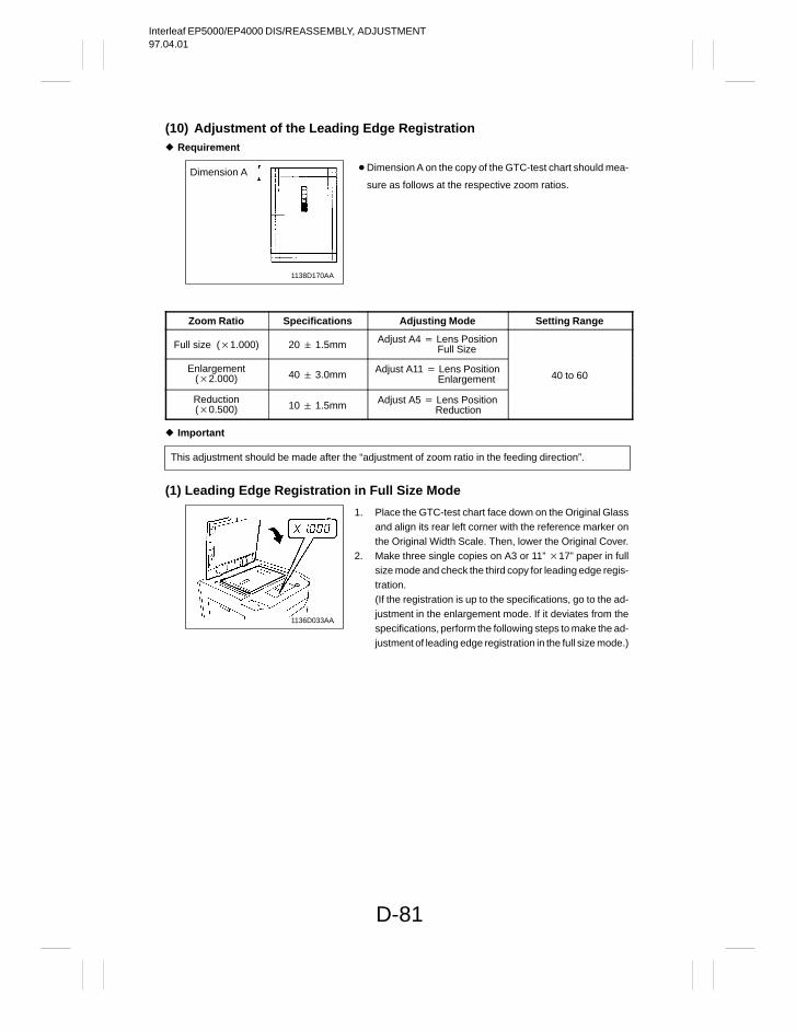
Interleaf EP5000/EP4000 DIS/REASSEMBLY, ADJUSTMENT97.04.01
D-81
(10) Adjustment of the Leading Edge Registration Requirement
1138D170AA
Dimension A
Zoom Ratio Specifications Adjusting Mode Setting Range
Full size (1.000) 20 1.5mm Adjust A4 Lens Position Full Size
Enlargement(2.000) 40 3.0mm Adjust A11 Lens Position
Enlargement 40 to 60
Reduction(0.500) 10 1.5mm Adjust A5 Lens Position
Reduction
Important
This adjustment should be made after the “adjustment of zoom ratio in the feeding direction”.
(1) Leading Edge Registration in Full Size Mode
1136D033AA
Dimension A on the copy of the GTC-test chart should mea-
sure as follows at the respective zoom ratios.
1. Place the GTC-test chart face down on the Original Glassand align its rear left corner with the reference marker onthe Original Width Scale. Then, lower the Original Cover.
2. Make three single copies on A3 or 11” 17” paper in fullsize mode and check the third copy for leading edge regis-tration.(If the registration is up to the specifications, go to the ad-justment in the enlargement mode. If it deviates from thespecifications, perform the following steps to make the ad-justment of leading edge registration in the full size mode.)
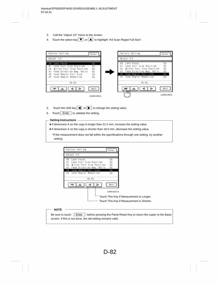
Interleaf EP5000/EP4000 DIS/REASSEMBLY, ADJUSTMENT97.04.01
D-82
3. Call the “Adjust 1/2” menu to the screen.
4. Touch the select key or to highlight “A4 Scan Regist Full Size”.
1156D148CA1156D138CA
5. Touch the shift key or to change the setting value.
6. Touch Enter to validate the setting.
If dimension A on the copy is longer than 21.5 mm, increase the setting value.
If dimension A on the copy is shorter than 18.5 mm, decrease the setting value.
*If the measurement does not fall within the specifications through one setting, try another setting.
Setting Instructions
Touch This Key if Measurement is Shorter.
Touch This Key if Measurement is Longer.
1156D152CA
NOTE
Be sure to touch Enter before pressing the Panel Reset Key to return the copier to the Basicscreen. If this is not done, the old setting remains valid.
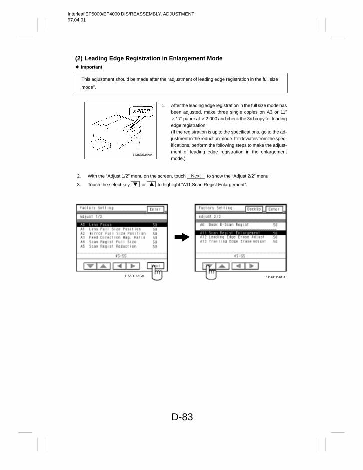
Interleaf EP5000/EP4000 DIS/REASSEMBLY, ADJUSTMENT97.04.01
D-83
(2) Leading Edge Registration in Enlargement Mode Important
This adjustment should be made after the “adjustment of leading edge registration in the full size
mode”.
1136D034AA
2. With the “Adjust 1/2” menu on the screen, touch Next to show the “Adjust 2/2” menu.
3. Touch the select key or to highlight “A11 Scan Regist Enlargement”.
1156D156CA1156D166CA
1. After the leading edge registration in the full size mode hasbeen adjusted, make three single copies on A3 or 11”17” paper at 2.000 and check the 3rd copy for leadingedge registration.(If the registration is up to the specifications, go to the ad-justment in the reduction mode. If it deviates from the spec-ifications, perform the following steps to make the adjust-ment of leading edge registration in the enlargementmode.)
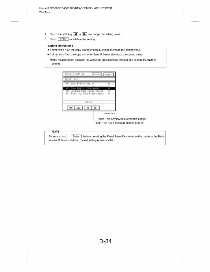
Interleaf EP5000/EP4000 DIS/REASSEMBLY, ADJUSTMENT97.04.01
D-84
4. Touch the shift key or to change the setting value.
5. Touch Enter to validate the setting.
If dimension A on the copy is longer than 43.0 mm, increase the setting value.
If dimension A on the copy is shorter than 37.0 mm, decrease the setting value.
*If the measurement does not fall within the specifications through one setting, try another setting.
Setting Instructions
Touch This Key if Measurement is Longer.Touch This Key if Measurement is Shorter.
1156D149CA
NOTE
Be sure to touch Enter before pressing the Panel Reset Key to return the copier to the Basicscreen. If this is not done, the old setting remains valid.
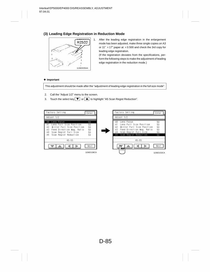
Interleaf EP5000/EP4000 DIS/REASSEMBLY, ADJUSTMENT97.04.01
D-85
(3) Leading Edge Registration in Reduction Mode
1136D035AA
Important
This adjustment should be made after the “adjustment of leading edge registration in the full size mode”.
2. Call the “Adjust 1/2” menu to the screen.
3. Touch the select key or to highlight “A5 Scan Regist Reduction”.
1156D138CA 1156D153CA
1. After the leading edge registration in the enlargementmode has been adjusted, make three single copies on A3or 11” 17” paper at 0.500 and check the 3rd copy forleading edge registration.(If the registration deviates from the specifications, per-form the following steps to make the adjustment of leadingedge registration in the reduction mode.)
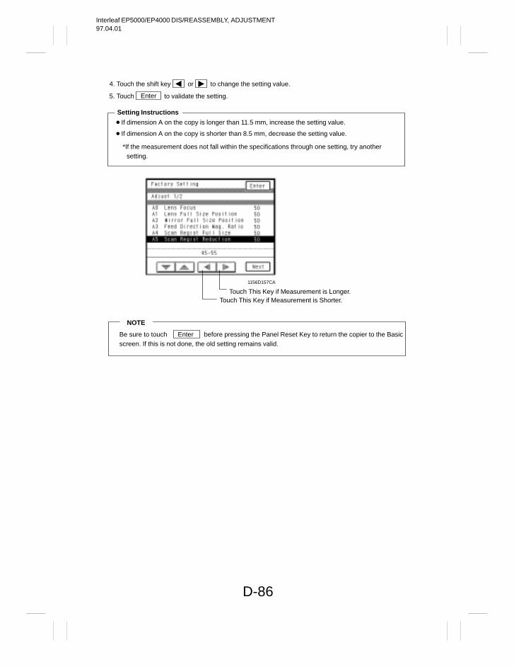
Interleaf EP5000/EP4000 DIS/REASSEMBLY, ADJUSTMENT97.04.01
D-86
4. Touch the shift key or to change the setting value.
5. Touch Enter to validate the setting.
If dimension A on the copy is longer than 11.5 mm, increase the setting value.
If dimension A on the copy is shorter than 8.5 mm, decrease the setting value.
*If the measurement does not fall within the specifications through one setting, try another setting.
Setting Instructions
Touch This Key if Measurement is Longer.Touch This Key if Measurement is Shorter.
1156D157CA
NOTE
Be sure to touch Enter before pressing the Panel Reset Key to return the copier to the Basicscreen. If this is not done, the old setting remains valid.
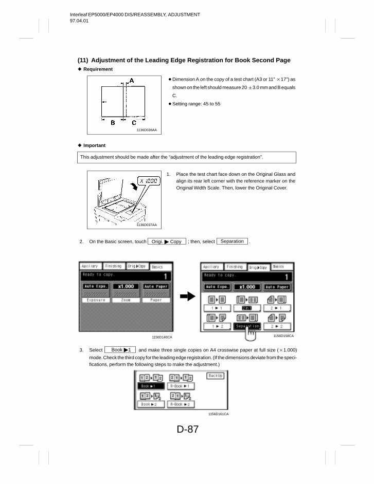
Interleaf EP5000/EP4000 DIS/REASSEMBLY, ADJUSTMENT97.04.01
D-87
(11) Adjustment of the Leading Edge Registration for Book Second Page Requirement
1136D036AA
Important
This adjustment should be made after the “adjustment of the leading edge registration”.
1136D037AA
2. On the Basic screen, touch Origi. Copy ; then, select Separation .
1156D140CA 1156D158CA
3. Select Book 1 and make three single copies on A4 crosswise paper at full size (1.000)
mode. Check the third copy for the leading edge registration. (If the dimensions deviate from the speci-fications, perform the following steps to make the adjustment.)
1156D161CA
Dimension A on the copy of a test chart (A3 or 11” 17”) as
shown on the left should measure 20 3.0 mm and B equals
C.
Setting range: 45 to 55
1. Place the test chart face down on the Original Glass andalign its rear left corner with the reference marker on theOriginal Width Scale. Then, lower the Original Cover.
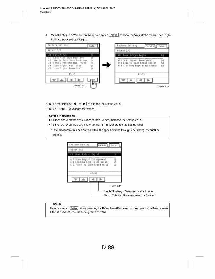
Interleaf EP5000/EP4000 DIS/REASSEMBLY, ADJUSTMENT97.04.01
D-88
4. With the “Adjust 1/2” menu on the screen, touch Next to show the “Adjust 2/2” menu. Then, high-
light “A6 Book B-Scan Regist”.
1156D163CA1156D166CA
5. Touch the shift key or to change the setting value.
6. Touch Enter to validate the setting.
If dimension A on the copy is longer than 23 mm, increase the setting value.
If dimension A on the copy is shorter than 17 mm, decrease the setting value.
*If the measurement does not fall within the specifications through one setting, try another
setting.
Setting Instructions
Touch This Key if Measurement is Longer.
Touch This Key if Measurement is Shorter.
1156D163CA
NOTE
Be sure to touch Enter before pressing the Panel Reset Key to return the copier to the Basic screen.If this is not done, the old setting remains valid.
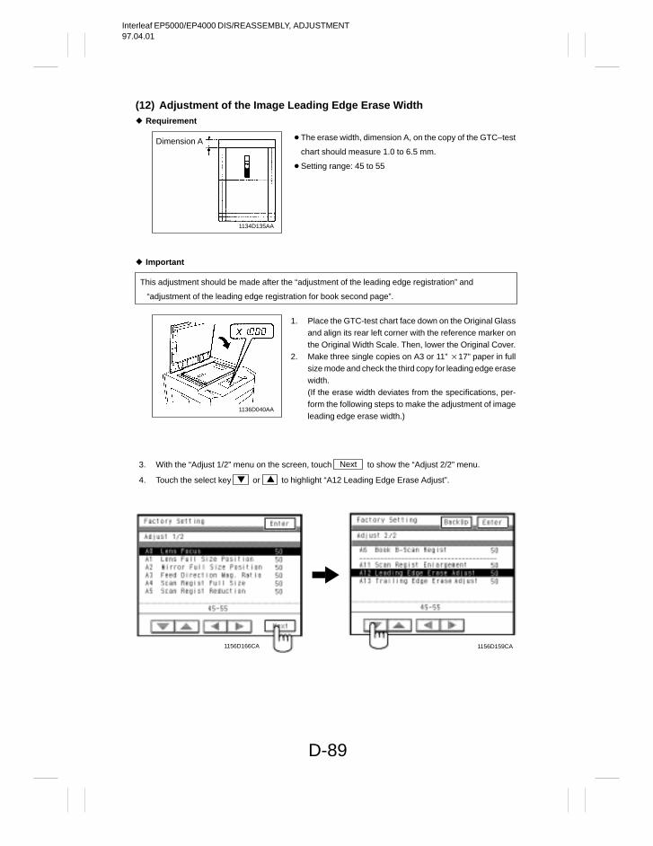
Interleaf EP5000/EP4000 DIS/REASSEMBLY, ADJUSTMENT97.04.01
D-89
(12) Adjustment of the Image Leading Edge Erase Width Requirement
1134D135AA
Dimension A
Important
This adjustment should be made after the “adjustment of the leading edge registration” and
“adjustment of the leading edge registration for book second page”.
1136D040AA
3. With the “Adjust 1/2” menu on the screen, touch Next to show the “Adjust 2/2” menu.
4. Touch the select key or to highlight “A12 Leading Edge Erase Adjust”.
1156D159CA1156D166CA
The erase width, dimension A, on the copy of the GTC–test
chart should measure 1.0 to 6.5 mm.
Setting range: 45 to 55
1. Place the GTC-test chart face down on the Original Glassand align its rear left corner with the reference marker onthe Original Width Scale. Then, lower the Original Cover.
2. Make three single copies on A3 or 11” 17” paper in fullsize mode and check the third copy for leading edge erasewidth.(If the erase width deviates from the specifications, per-form the following steps to make the adjustment of imageleading edge erase width.)
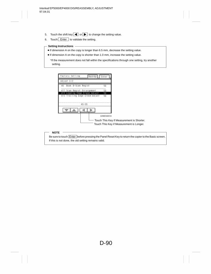
Interleaf EP5000/EP4000 DIS/REASSEMBLY, ADJUSTMENT97.04.01
D-90
5. Touch the shift key or to change the setting value.
6. Touch Enter to validate the setting.
If dimension A on the copy is longer than 6.5 mm, decrease the setting value.
If dimension A on the copy is shorter than 1.0 mm, increase the setting value.
*If the measurement does not fall within the specifications through one setting, try another setting.
Setting Instructions
Touch This Key if Measurement is Longer.Touch This Key if Measurement is Shorter.
1156D162CA
NOTE
Be sure to touch Enter before pressing the Panel Reset Key to return the copier to the Basic screen.If this is not done, the old setting remains valid.
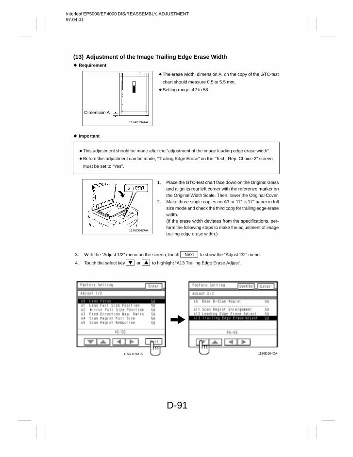
Interleaf EP5000/EP4000 DIS/REASSEMBLY, ADJUSTMENT97.04.01
D-91
(13) Adjustment of the Image Trailing Edge Erase Width Requirement
1134D134AA
Dimension A
Important
This adjustment should be made after the “adjustment of the image leading edge erase width”.
Before this adjustment can be made, “Trailing Edge Erase” on the “Tech. Rep. Choice 2” screen
must be set to “Yes”.
1136D042AA
3. With the “Adjust 1/2” menu on the screen, touch Next to show the “Adjust 2/2” menu.
4. Touch the select key or to highlight “A13 Trailing Edge Erase Adjust”.
1156D166CA 1156D164CA
The erase width, dimension A, on the copy of the GTC-test
chart should measure 0.5 to 5.5 mm.
Setting range: 42 to 58.
1. Place the GTC-test chart face down on the Original Glassand align its rear left corner with the reference marker onthe Original Width Scale. Then, lower the Original Cover.
2. Make three single copies on A3 or 11” 17” paper in fullsize mode and check the third copy for trailing edge erasewidth.(If the erase width deviates from the specifications, per-form the following steps to make the adjustment of imagetrailing edge erase width.)
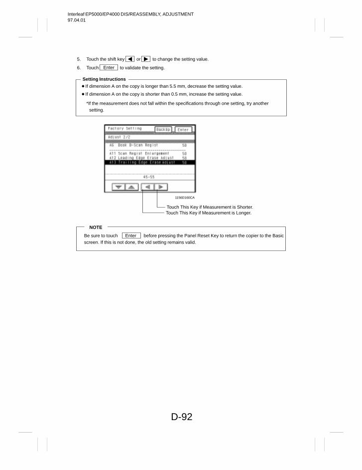
Interleaf EP5000/EP4000 DIS/REASSEMBLY, ADJUSTMENT97.04.01
D-92
5. Touch the shift key or to change the setting value.
6. Touch Enter to validate the setting.
If dimension A on the copy is longer than 5.5 mm, decrease the setting value.
If dimension A on the copy is shorter than 0.5 mm, increase the setting value.
*If the measurement does not fall within the specifications through one setting, try anothersetting.
Setting Instructions
Touch This Key if Measurement is Longer.Touch This Key if Measurement is Shorter.
1156D160CA
NOTE
Be sure to touch Enter before pressing the Panel Reset Key to return the copier to the Basicscreen. If this is not done, the old setting remains valid.
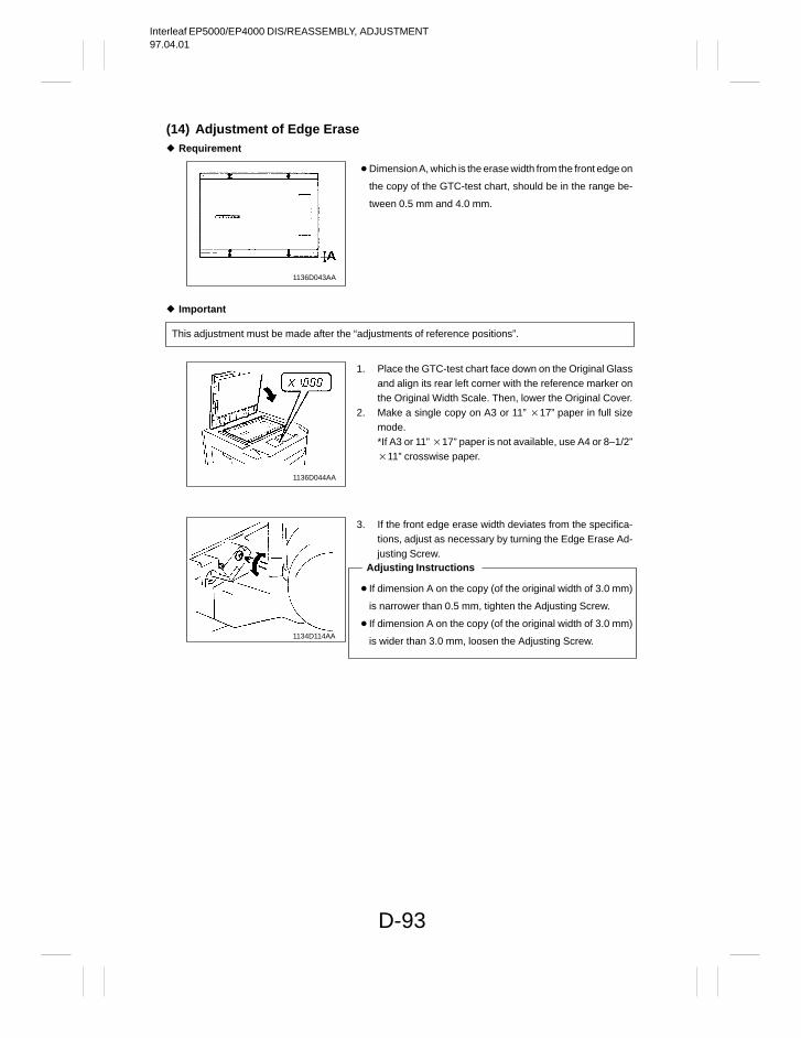
Interleaf EP5000/EP4000 DIS/REASSEMBLY, ADJUSTMENT97.04.01
D-93
(14) Adjustment of Edge Erase Requirement
1136D043AA
Important
This adjustment must be made after the “adjustments of reference positions”.
1136D044AA
1134D114AA
Dimension A, which is the erase width from the front edge on
the copy of the GTC-test chart, should be in the range be-
tween 0.5 mm and 4.0 mm.
1. Place the GTC-test chart face down on the Original Glassand align its rear left corner with the reference marker onthe Original Width Scale. Then, lower the Original Cover.
2. Make a single copy on A3 or 11” 17” paper in full sizemode.*If A3 or 11” 17” paper is not available, use A4 or 8–1/2”11” crosswise paper.
3. If the front edge erase width deviates from the specifica-tions, adjust as necessary by turning the Edge Erase Ad-justing Screw.
If dimension A on the copy (of the original width of 3.0 mm)
is narrower than 0.5 mm, tighten the Adjusting Screw.
If dimension A on the copy (of the original width of 3.0 mm)
is wider than 3.0 mm, loosen the Adjusting Screw.
Adjusting Instructions
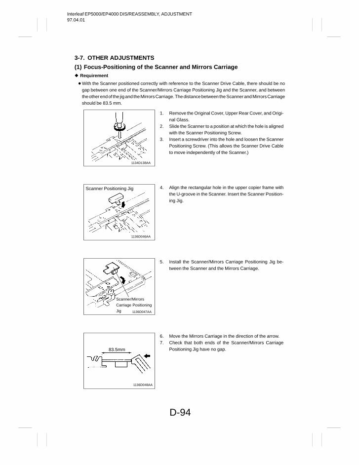
Interleaf EP5000/EP4000 DIS/REASSEMBLY, ADJUSTMENT97.04.01
D-94
3-7. OTHER ADJUSTMENTS
(1) Focus-Positioning of the Scanner and Mirrors Carriage Requirement
With the Scanner positioned correctly with reference to the Scanner Drive Cable, there should be nogap between one end of the Scanner/Mirrors Carriage Positioning Jig and the Scanner, and betweenthe other end of the jig and the Mirrors Carriage. The distance between the Scanner and Mirrors Carriageshould be 83.5 mm.
1134D138AA
1136D046AA
Scanner Positioning Jig
Scanner/Mirrors
Carriage Positioning
Jig 1136D047AA
1136D048AA
83.5mm
1. Remove the Original Cover, Upper Rear Cover, and Origi-nal Glass.
2. Slide the Scanner to a position at which the hole is alignedwith the Scanner Positioning Screw.
3. Insert a screwdriver into the hole and loosen the ScannerPositioning Screw. (This allows the Scanner Drive Cableto move independently of the Scanner.)
4. Align the rectangular hole in the upper copier frame withthe U-groove in the Scanner. Insert the Scanner Position-ing Jig.
5. Install the Scanner/Mirrors Carriage Positioning Jig be-tween the Scanner and the Mirrors Carriage.
6. Move the Mirrors Carriage in the direction of the arrow.7. Check that both ends of the Scanner/Mirrors Carriage
Positioning Jig have no gap.
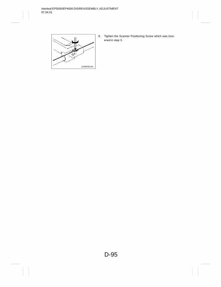
Interleaf EP5000/EP4000 DIS/REASSEMBLY, ADJUSTMENT97.04.01
D-95
1139D051AA
8. Tighten the Scanner Positioning Screw which was loos-ened in step 3.
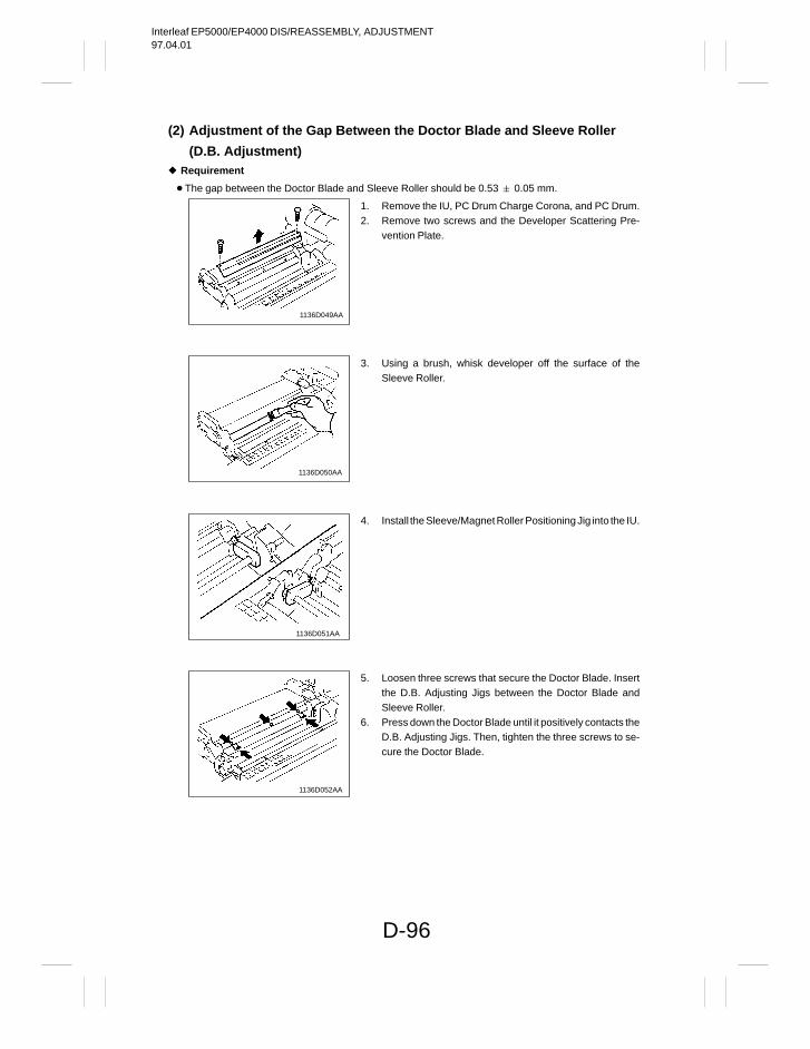
Interleaf EP5000/EP4000 DIS/REASSEMBLY, ADJUSTMENT97.04.01
D-96
(2) Adjustment of the Gap Between the Doctor Blade and Sleeve Roller
(D.B. Adjustment) Requirement
The gap between the Doctor Blade and Sleeve Roller should be 0.53 0.05 mm.
1136D049AA
1136D050AA
1136D051AA
1136D052AA
1. Remove the IU, PC Drum Charge Corona, and PC Drum.2. Remove two screws and the Developer Scattering Pre-
vention Plate.
3. Using a brush, whisk developer off the surface of theSleeve Roller.
4. Install the Sleeve/Magnet Roller Positioning Jig into the IU.
5. Loosen three screws that secure the Doctor Blade. Insertthe D.B. Adjusting Jigs between the Doctor Blade andSleeve Roller.
6. Press down the Doctor Blade until it positively contacts theD.B. Adjusting Jigs. Then, tighten the three screws to se-cure the Doctor Blade.
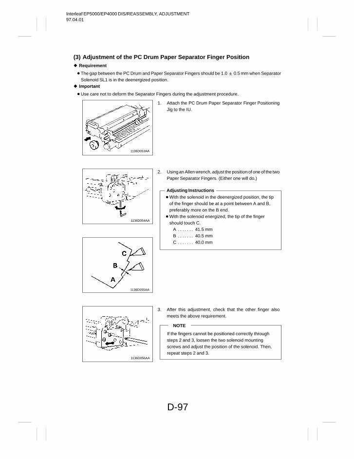
Interleaf EP5000/EP4000 DIS/REASSEMBLY, ADJUSTMENT97.04.01
D-97
(3) Adjustment of the PC Drum Paper Separator Finger Position Requirement
The gap between the PC Drum and Paper Separator Fingers should be 1.0 0.5 mm when SeparatorSolenoid SL1 is in the deenergized position.
Important
Use care not to deform the Separator Fingers during the adjustment procedure.
1136D053AA
1136D054AA
1136D055AA
1136D056AA
1. Attach the PC Drum Paper Separator Finger PositioningJig to the IU.
2. Using an Allen wrench, adjust the position of one of the twoPaper Separator Fingers. (Either one will do.)
With the solenoid in the deenergized position, the tip of the finger should be at a point between A and B, preferably more on the B end.
With the solenoid energized, the tip of the finger should touch C.
A 41.5 mm. . . . . . . B 40.5 mm. . . . . . . C 40.0 mm. . . . . . .
Adjusting Instructions
3. After this adjustment, check that the other finger alsomeets the above requirement.
NOTE
If the fingers cannot be positioned correctly through steps 2 and 3, loosen the two solenoid mounting screws and adjust the position of the solenoid. Then,repeat steps 2 and 3.
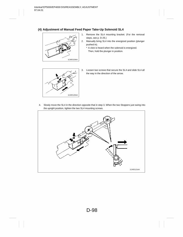
Interleaf EP5000/EP4000 DIS/REASSEMBLY, ADJUSTMENT97.04.01
D-98
(4) Adjustment of Manual Feed Paper Take-Up Solenoid SL4
1134D119AA
1134D120AA
4. Slowly move the SL4 in the direction opposite that in step 3. When the two Stoppers just swing intothe upright position, tighten the two SL4 mounting screws.
1134D121AA
1. Remove the SL4 mounting bracket. (For the removalsteps, see p. D-25.)
2. Manually bring SL4 into the energized position (plungerpushed in).* A click is heard when the solenoid is energized.
Then, hold the plunger in position.
3. Loosen two screws that secure the SL4 and slide SL4 allthe way in the direction of the arrow.
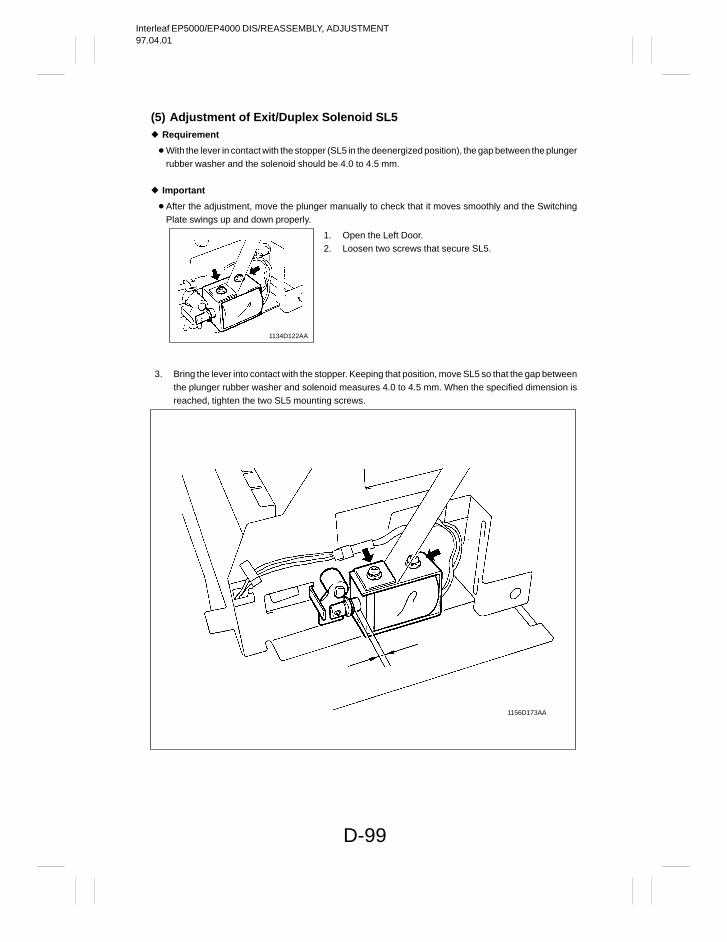
Interleaf EP5000/EP4000 DIS/REASSEMBLY, ADJUSTMENT97.04.01
D-99
(5) Adjustment of Exit/Duplex Solenoid SL5 Requirement
With the lever in contact with the stopper (SL5 in the deenergized position), the gap between the plungerrubber washer and the solenoid should be 4.0 to 4.5 mm.
Important
After the adjustment, move the plunger manually to check that it moves smoothly and the SwitchingPlate swings up and down properly.
1134D122AA
3. Bring the lever into contact with the stopper. Keeping that position, move SL5 so that the gap betweenthe plunger rubber washer and solenoid measures 4.0 to 4.5 mm. When the specified dimension isreached, tighten the two SL5 mounting screws.
1156D173AA
1. Open the Left Door.2. Loosen two screws that secure SL5.
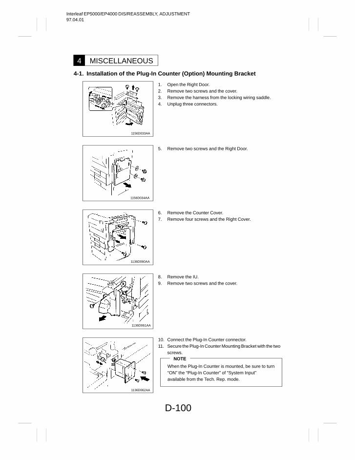
Interleaf EP5000/EP4000 DIS/REASSEMBLY, ADJUSTMENT97.04.01
D-100
MISCELLANEOUS4
4-1. Installation of the Plug-In Counter (Option) Mounting Bracket
1156D033AA
1156D034AA
1136D060AA
1136D061AA
1136D062AA
1. Open the Right Door.2. Remove two screws and the cover.3. Remove the harness from the locking wiring saddle.4. Unplug three connectors.
5. Remove two screws and the Right Door.
6. Remove the Counter Cover.7. Remove four screws and the Right Cover.
8. Remove the IU.9. Remove two screws and the cover.
10. Connect the Plug-In Counter connector.11. Secure the Plug-In Counter Mounting Bracket with the two
screws.NOTE
When the Plug-In Counter is mounted, be sure to turn “ON” the “Plug-In Counter” of “System Input” available from the Tech. Rep. mode.
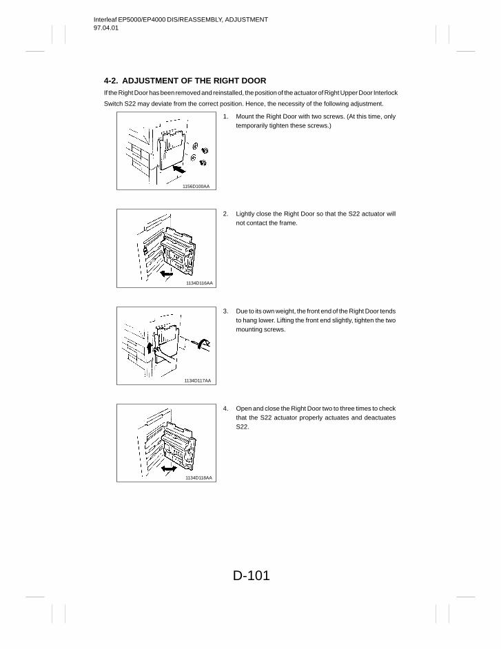
Interleaf EP5000/EP4000 DIS/REASSEMBLY, ADJUSTMENT97.04.01
D-101
4-2. ADJUSTMENT OF THE RIGHT DOORIf the Right Door has been removed and reinstalled, the position of the actuator of Right Upper Door Interlock
Switch S22 may deviate from the correct position. Hence, the necessity of the following adjustment.
1156D100AA
1134D116AA
1134D117AA
1134D118AA
1. Mount the Right Door with two screws. (At this time, onlytemporarily tighten these screws.)
2. Lightly close the Right Door so that the S22 actuator willnot contact the frame.
3. Due to its own weight, the front end of the Right Door tendsto hang lower. Lifting the front end slightly, tighten the twomounting screws.
4. Open and close the Right Door two to three times to checkthat the S22 actuator properly actuates and deactuatesS22.

Interleaf EP4000/EP5000 DIS/REASSEMBLY, ADJUSTMENT97.04.01
Copyright1997 MINOLTA Co., Ltd.
Printed in Japan
Use of this manual shouldbe strictly supervised to avoid disclosure of confidential information.
1156-7992-11 97046000
1156SBD000EA

Interleaf EP5000/EP4000 SWITCHES ON PWBs, TECH. REP. SETTINGS97.04.01
1156SBS000AA
Interleaf EP5000/EP4000 SWITCHES ON PWBs, TECH. REP. SETTINGS97.04.01
i
1156SBS000BA
CONTENTS
PRECAUTIONS FOR HANDLING THE PWBs1 S-1. . . . . . . . . . . . . . . . . . .
1-1. Precautions for Transportation and Storage S-1. . . . . . . . . . . . . . . . 1-2. Precautions for Replacement and Inspection S-1. . . . . . . . . . . . . . .
CONTROL PANEL KEYS AND TOUCH PANEL2 S-2. . . . . . . . . . . . . . . . .
2-1. Control Panel Keys S-2. . . . . . . . . . . . . . . . . . . . . . . . . . . . . . . . . . . . . 2-2. Explanation of the Touch Panel S-3. . . . . . . . . . . . . . . . . . . . . . . . . . .
FUNCTIONS OF SWITCHES AND POINTS ON PWB-I3 S-5. . . . . . . . . . .
3-1. PWB-I Location S-5. . . . . . . . . . . . . . . . . . . . . . . . . . . . . . . . . . . . . . . . . 3-2. Tech. Rep. Settings Switches Board PWB-I S-5. . . . . . . . . . . . . . . . .
USER’S CHOICE MODE4 S-7. . . . . . . . . . . . . . . . . . . . . . . . . . . . . . . . . . . .
4-1. User’s Choice Selection Screen S-7. . . . . . . . . . . . . . . . . . . . . . . . . . 4-2. User’s Choice Function Setting Procedure S-7. . . . . . . . . . . . . . . . . 4-3. User’s Choice Function Tree S-8. . . . . . . . . . . . . . . . . . . . . . . . . . . . . 4-4. Settings in the User’s Choice S-9. . . . . . . . . . . . . . . . . . . . . . . . . . . . .
TECH. REP. MODE5 S-16. . . . . . . . . . . . . . . . . . . . . . . . . . . . . . . . . . . . . . . . .
5-1. Tech. Rep. Mode Menu Screen S-16. . . . . . . . . . . . . . . . . . . . . . . . . . . 5-2. Tech. Rep. Mode Function Setting Procedure S-16. . . . . . . . . . . . . . . 5-3. Tech. Rep. Mode Function Tree S-17. . . . . . . . . . . . . . . . . . . . . . . . . . . 5-4. Settings in the Tech. Rep. Mode S-19. . . . . . . . . . . . . . . . . . . . . . . . . .
1. Function S-19. . . . . . . . . . . . . . . . . . . . . . . . . . . . . . . . . . . . . . . . . . . . . 2. Tech. Rep. Choice S-20. . . . . . . . . . . . . . . . . . . . . . . . . . . . . . . . . . . . 3. System Input S-24. . . . . . . . . . . . . . . . . . . . . . . . . . . . . . . . . . . . . . . . . 4. Counter S-25. . . . . . . . . . . . . . . . . . . . . . . . . . . . . . . . . . . . . . . . . . . . . 5. I/O Check S-32. . . . . . . . . . . . . . . . . . . . . . . . . . . . . . . . . . . . . . . . . . . . 6. Last Trouble S-34. . . . . . . . . . . . . . . . . . . . . . . . . . . . . . . . . . . . . . . . . . 7. ROM Version S-34. . . . . . . . . . . . . . . . . . . . . . . . . . . . . . . . . . . . . . . . . 8. RD Mode S-35. . . . . . . . . . . . . . . . . . . . . . . . . . . . . . . . . . . . . . . . . . . . 9. Accessory Test S-37. . . . . . . . . . . . . . . . . . . . . . . . . . . . . . . . . . . . . . .
10. Level History S-39. . . . . . . . . . . . . . . . . . . . . . . . . . . . . . . . . . . . . . . . . 11. Machine Status S-40. . . . . . . . . . . . . . . . . . . . . . . . . . . . . . . . . . . . . . . 12. Admin. Mode S-40. . . . . . . . . . . . . . . . . . . . . . . . . . . . . . . . . . . . . . . . .
Interleaf EP5000/EP4000 SWITCHES ON PWBs, TECH. REP. SETTINGS97.04.01
ii
CONTENTS
FACTORY SETTING6 S-41. . . . . . . . . . . . . . . . . . . . . . . . . . . . . . . . . . . . . . . .
6-1. Factory Setting Menu Screen S-41. . . . . . . . . . . . . . . . . . . . . . . . . . . . . 6-2. Factory Setting Function Setting Procedure S-41. . . . . . . . . . . . . . . . 6-3. Factory Setting Function Tree S-42. . . . . . . . . . . . . . . . . . . . . . . . . . . .
1. Function S-42. . . . . . . . . . . . . . . . . . . . . . . . . . . . . . . . . . . . . . . . . . . . 2. Adjust S-44. . . . . . . . . . . . . . . . . . . . . . . . . . . . . . . . . . . . . . . . . . . . . .
Interleaf EP5000/EP4000 SWITCHES ON PWBs, TECH. REP. SETTINGS97.04.01
S-1
1151SBS0100A
PRECAUTIONS FOR HANDLING THE PWBs11151SBS0101A
1-1. Precautions for Transportation and Storagea) Before transporting or storing the PWBs, put them in protective conductive cases or bags so that they
are not subjected to high temperature (and they are not exposed to direct sunlight).b) Protect the PWBs from any external force so that they are not bent or damaged.c) Once the PWB has been removed from its conductive case or bag, never place it directly on an object
that is easily charged with static electricity (such as a carpet or plastic bag).d) Do not touch the parts and printed patterns on the PWBs with bare hands.
1151SBS0102A
1-2. Precautions for Replacement and Inspectiona) Whenever replacing the PWB, make sure that the power cord of the copier has been unplugged.b) When the power is on, the connectors must not be plugged in or unplugged.c) Use care not to strap the pins of an IC with a metal tool.d) When touching the PWB, wear a wrist strap and connect its cord to a securely grounded place when-
ever possible. If you cannot wear a wrist strap, touch the metal part to discharge static electricity be-fore touching the PWB.
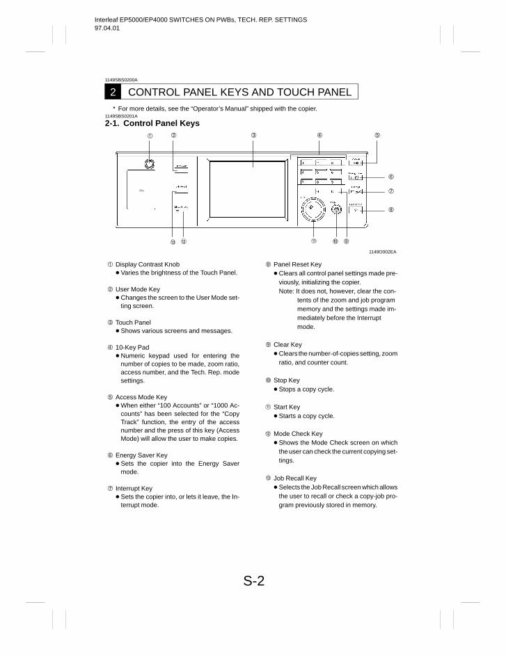
Interleaf EP5000/EP4000 SWITCHES ON PWBs, TECH. REP. SETTINGS97.04.01
S-2
1149SBS0200A
CONTROL PANEL KEYS AND TOUCH PANEL2* For more details, see the “Operator’s Manual” shipped with the copier.
1149SBS0201A
2-1. Control Panel Keys
1149O002EA
Display Contrast Knob Varies the brightness of the Touch Panel.
User Mode Key Changes the screen to the User Mode set-
ting screen.
Touch Panel Shows various screens and messages.
10-Key Pad Numeric keypad used for entering the
number of copies to be made, zoom ratio,access number, and the Tech. Rep. modesettings.
Access Mode Key When either “100 Accounts” or “1000 Ac-
counts” has been selected for the “CopyTrack” function, the entry of the accessnumber and the press of this key (AccessMode) will allow the user to make copies.
Energy Saver Key Sets the copier into the Energy Saver
mode.
Interrupt Key Sets the copier into, or lets it leave, the In-
terrupt mode.
Panel Reset Key Clears all control panel settings made pre-
viously, initializing the copier.Note: It does not, however, clear the con-
tents of the zoom and job programmemory and the settings made im-mediately before the Interruptmode.
Clear Key Clears the number-of-copies setting, zoom
ratio, and counter count.
Stop Key Stops a copy cycle.
Start Key Starts a copy cycle.
Mode Check Key Shows the Mode Check screen on which
the user can check the current copying set-tings.
Job Recall Key Selects the Job Recall screen which allows
the user to recall or check a copy-job pro-gram previously stored in memory.
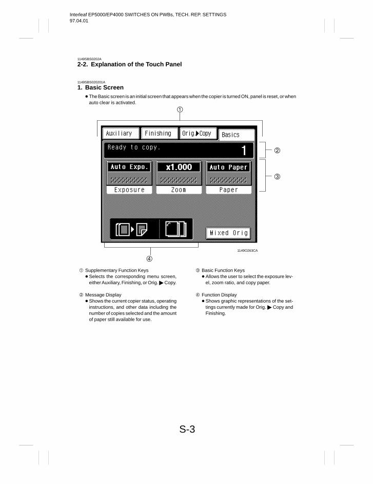
Interleaf EP5000/EP4000 SWITCHES ON PWBs, TECH. REP. SETTINGS97.04.01
S-3
1149SBS0202A
2-2. Explanation of the Touch Panel
1149SBS020201A
1. Basic Screen The Basic screen is an initial screen that appears when the copier is turned ON, panel is reset, or when
auto clear is activated.
1149O263CA
Supplementary Function Keys Selects the corresponding menu screen,
either Auxiliary, Finishing, or Orig. Copy.
Message Display Shows the current copier status, operating
instructions, and other data including thenumber of copies selected and the amountof paper still available for use.
Basic Function Keys Allows the user to select the exposure lev-
el, zoom ratio, and copy paper.
Function Display Shows graphic representations of the set-
tings currently made for Orig. Copy andFinishing.
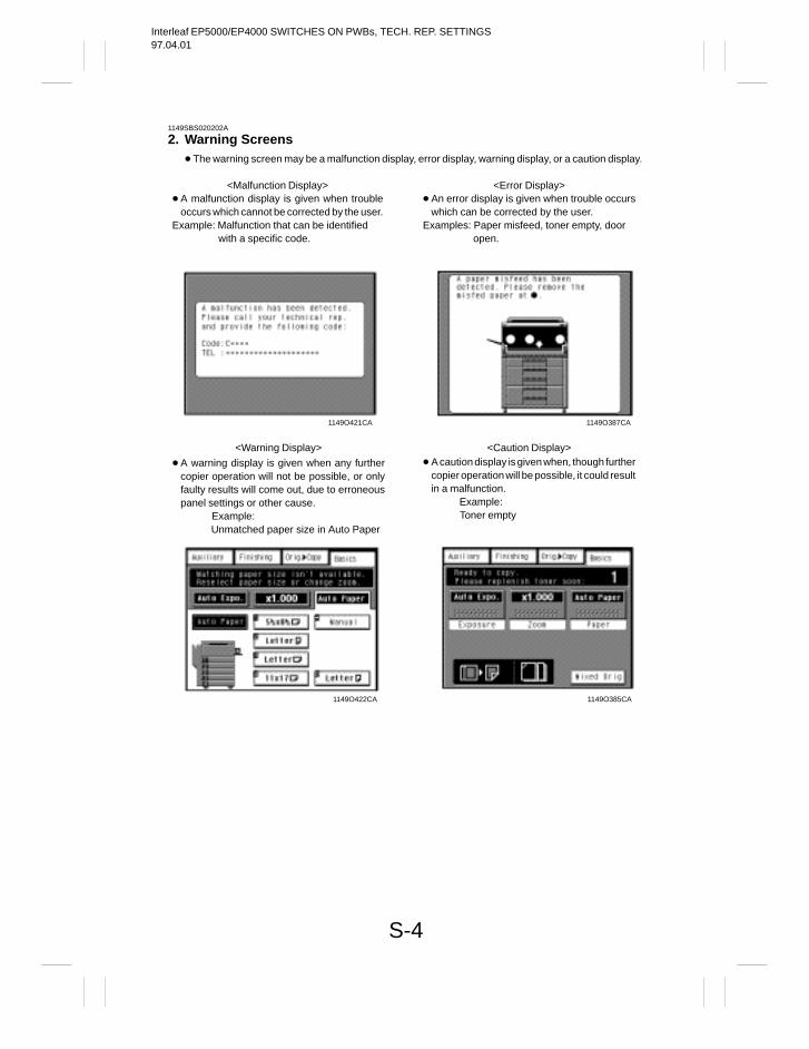
Interleaf EP5000/EP4000 SWITCHES ON PWBs, TECH. REP. SETTINGS97.04.01
S-4
1149SBS020202A
2. Warning Screens The warning screen may be a malfunction display, error display, warning display, or a caution display.
<Malfunction Display> A malfunction display is given when trouble
occurs which cannot be corrected by the user.Example: Malfunction that can be identified
with a specific code.
<Error Display> An error display is given when trouble occurs
which can be corrected by the user.Examples: Paper misfeed, toner empty, door
open.
1149O387CA1149O421CA
<Warning Display> <Caution Display>
1149O422CA 1149O385CA
A warning display is given when any furthercopier operation will not be possible, or onlyfaulty results will come out, due to erroneouspanel settings or other cause. Example: Unmatched paper size in Auto Paper
A caution display is given when, though furthercopier operation will be possible, it could resultin a malfunction. Example: Toner empty
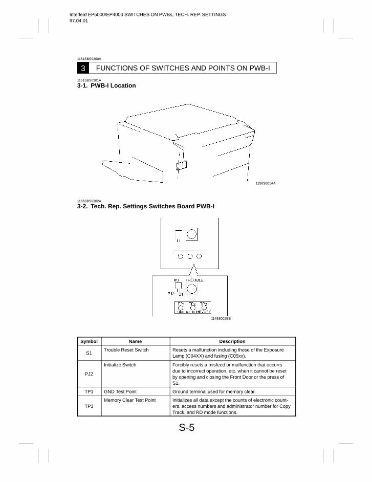
Interleaf EP5000/EP4000 SWITCHES ON PWBs, TECH. REP. SETTINGS97.04.01
S-5
1151SBS0300A
FUNCTIONS OF SWITCHES AND POINTS ON PWB-I31151SBS0301A
3-1. PWB-I Location
1156S001AA
1156SBS0302A
3-2. Tech. Rep. Settings Switches Board PWB-I
1149S002BB
Symbol Name Description
S1Trouble Reset Switch Resets a malfunction including those of the Exposure
Lamp (C04XX) and fusing (C05xx).
PJ2
Initialize Switch Forcibly resets a misfeed or malfunction that occurrs due to incorrect operation, etc. when it cannot be resetby opening and closing the Front Door or the press ofS1.
TP1 GND Test Point Ground terminal used for memory clear.
TP3Memory Clear Test Point Initializes all data except the counts of electronic count-
ers, access numbers and administrator number for CopyTrack, and RD mode functions.
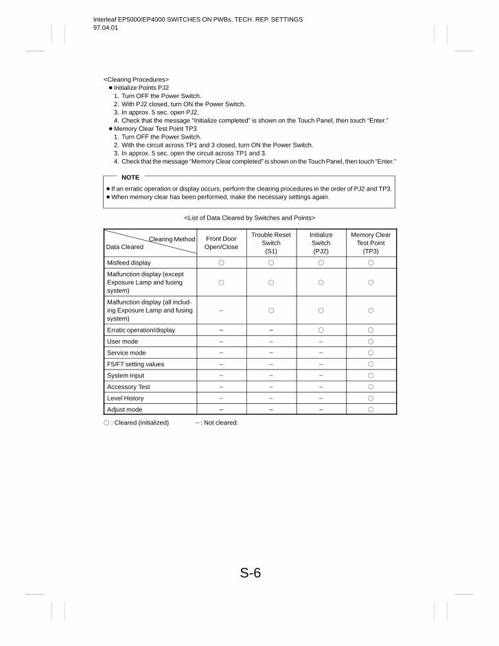
Interleaf EP5000/EP4000 SWITCHES ON PWBs, TECH. REP. SETTINGS97.04.01
S-6
<Clearing Procedures> Initialize Points PJ2
1. Turn OFF the Power Switch.2. With PJ2 closed, turn ON the Power Switch.3. In approx. 5 sec. open PJ2.4. Check that the message “Initialize completed” is shown on the Touch Panel, then touch “Enter.”
Memory Clear Test Point TP31. Turn OFF the Power Switch.2. With the circuit across TP1 and 3 closed, turn ON the Power Switch.3. In approx. 5 sec. open the circuit across TP1 and 3.4. Check that the message “Memory Clear completed” is shown on the Touch Panel, then touch “Enter.”
NOTE
If an erratic operation or display occurs, perform the clearing procedures in the order of PJ2 and TP3. When memory clear has been performed, make the necessary settings again.
<List of Data Cleared by Switches and Points>
Clearing MethodData Cleared
Front DoorOpen/Close
Trouble ResetSwitch(S1)
InitializeSwitch(PJ2)
Memory ClearTest Point
(TP3)
Misfeed display
Malfunction display (exceptExposure Lamp and fusingsystem)
Malfunction display (all includ-ing Exposure Lamp and fusingsystem)
Erratic operation/display
User mode
Service mode
F5/F7 setting values
System Input
Accessory Test
Level History
Adjust mode
: Cleared (initialized) : Not cleared:
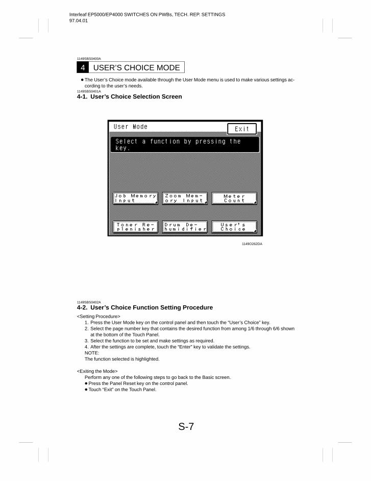
Interleaf EP5000/EP4000 SWITCHES ON PWBs, TECH. REP. SETTINGS97.04.01
S-7
1149SBS0400A
USER’S CHOICE MODE4 The User’s Choice mode available through the User Mode menu is used to make various settings ac-
cording to the user’s needs.1149SBS0401A
4-1. User’s Choice Selection Screen
1149O262DA
1149SBS0402A
4-2. User’s Choice Function Setting Procedure<Setting Procedure>
1. Press the User Mode key on the control panel and then touch the “User’s Choice” key.2. Select the page number key that contains the desired function from among 1/6 through 6/6 shown
at the bottom of the Touch Panel.3. Select the function to be set and make settings as required.4. After the settings are complete, touch the “Enter” key to validate the settings.NOTE:The function selected is highlighted.
<Exiting the Mode>Perform any one of the following steps to go back to the Basic screen. Press the Panel Reset key on the control panel. Touch “Exit” on the Touch Panel.
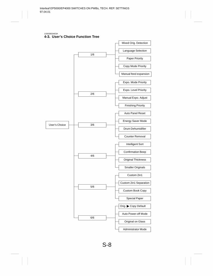
Interleaf EP5000/EP4000 SWITCHES ON PWBs, TECH. REP. SETTINGS97.04.01
S-8
1156SBS0403A
4-3. User’s Choice Function Tree
User’s Choice
1/6
Mixed Orig. Detection
Language Selection
Paper Priority
Copy Mode Priority
Expo. Mode Priority
Expo. Level Priority
Manual Expo. Adjust
Finishing Priority
Auto Panel Reset
Energy Saver Mode
Drum Dehumidifier
Counter Removal
Intelligent Sort
Confirmation Beep
Original Thickness
Smaller Originals
Custom 2in1
Custom 2in1 Separation
Custom Book Copy
Special Paper
Orig. Copy Default
Auto Power-off Mode
Original on Glass
Administrator Mode
2/6
3/6
4/6
5/6
6/6
Manual feed expansion
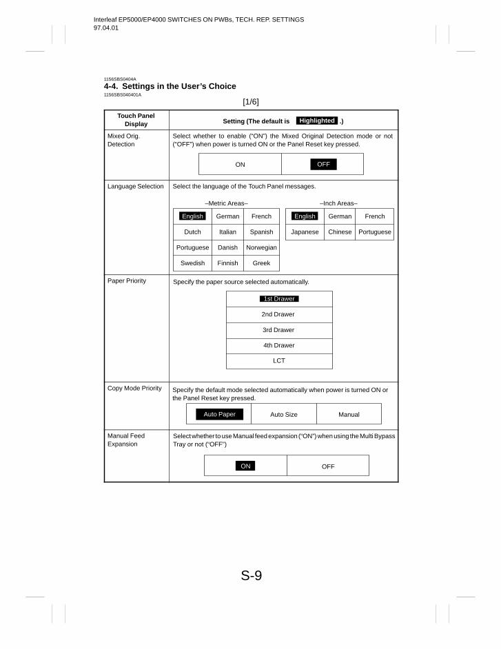
Interleaf EP5000/EP4000 SWITCHES ON PWBs, TECH. REP. SETTINGS97.04.01
S-9
1156SBS0404A
4-4. Settings in the User’s Choice1156SBS040401A
[1/6]
Touch PanelDisplay Setting (The default is .)Highlighted
Mixed Orig.Detection
Select whether to enable (“ON”) the Mixed Original Detection mode or not(“OFF”) when power is turned ON or the Panel Reset key pressed.
ON OFF
Language Selection
English
Select the language of the Touch Panel messages.
French
Dutch Italian Spanish
Portuguese Danish Norwegian
Swedish Finnish Greek
–Metric Areas–
English German French
Japanese Chinese Portuguese
–Inch Areas–
German
Paper Priority Specify the paper source selected automatically.
1st Drawer
2nd Drawer
3rd Drawer
4th Drawer
LCT
Copy Mode Priority Specify the default mode selected automatically when power is turned ON orthe Panel Reset key pressed.
ManualAuto Paper Auto Size
Manual Feed Expansion
Select whether to use Manual feed expansion (“ON”) when using the Multi BypassTray or not (“OFF”)
OFFON
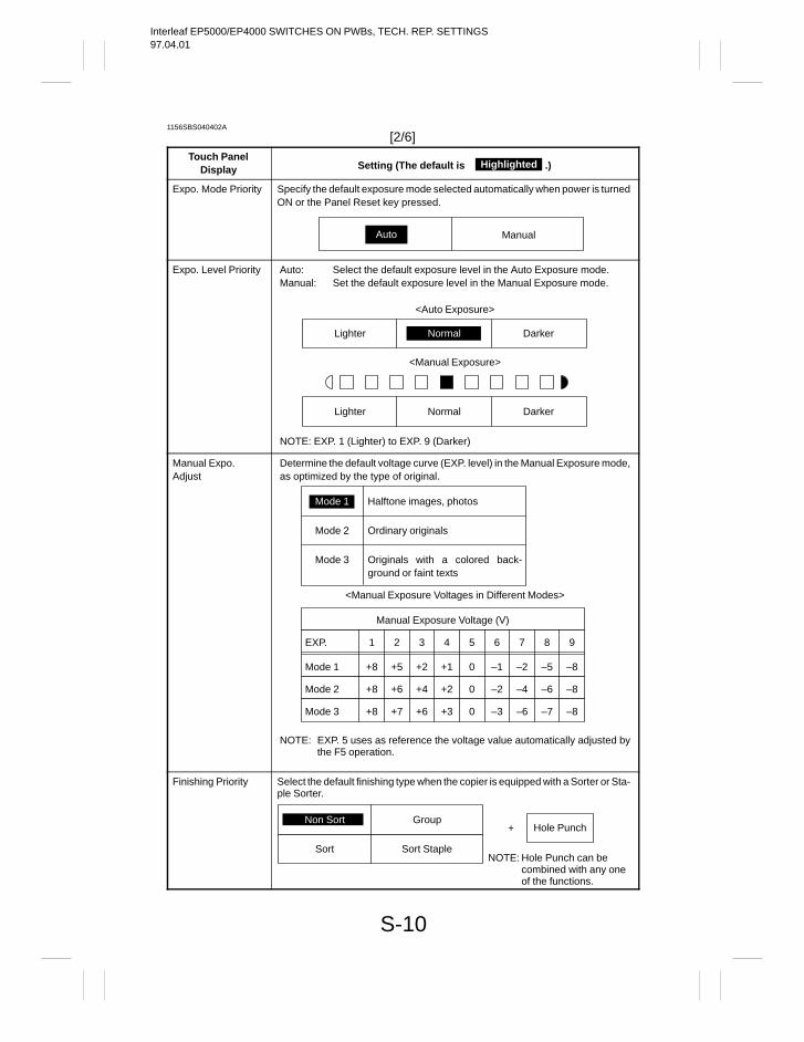
Interleaf EP5000/EP4000 SWITCHES ON PWBs, TECH. REP. SETTINGS97.04.01
S-10
1156SBS040402A
[2/6]Touch Panel
Display Setting (The default is .)Highlighted
Expo. Mode Priority Specify the default exposure mode selected automatically when power is turnedON or the Panel Reset key pressed.
ManualAuto
Expo. Level Priority Auto: Select the default exposure level in the Auto Exposure mode.Manual: Set the default exposure level in the Manual Exposure mode.
<Auto Exposure>
<Manual Exposure>
NOTE: EXP. 1 (Lighter) to EXP. 9 (Darker)
Lighter Darker
NormalLighter Darker
Normal
Manual Expo.Adjust
Determine the default voltage curve (EXP. level) in the Manual Exposure mode,as optimized by the type of original.
<Manual Exposure Voltages in Different Modes>
NOTE: EXP. 5 uses as reference the voltage value automatically adjusted bythe F5 operation.
Mode 1
Mode 1 Halftone images, photos
Mode 2 Ordinary originals
Mode 3 Originals with a colored back-ground or faint texts
EXP.
Manual Exposure Voltage (V)
Mode 2
Mode 3
1 2 3 4 5 6 7 8 9
+8
+8
+8
+5 +2 +1 0 –1 –2 –5 –8
+6 +4 +2 0 –2 –4 –6 –8
+7 +6 +3 0 –3 –6 –7 –8
Finishing Priority Select the default finishing type when the copier is equipped with a Sorter or Sta-ple Sorter.
Non Sort Group
Sort Sort Staple
+ Hole Punch
NOTE: Hole Punch can becombined with any oneof the functions.
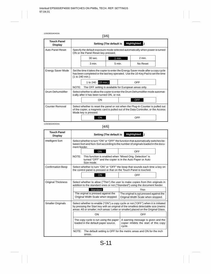
Interleaf EP5000/EP4000 SWITCHES ON PWBs, TECH. REP. SETTINGS97.04.01
S-11
1156SBS040403A
[3/6]
Touch PanelDisplay Setting (The default is .)Highlighted
Auto Panel Reset Specify the default exposure mode selected automatically when power is turnedON or the Panel Reset key pressed.
1 min.30 sec. 2 min.
5 min.3 min. No Reset
Energy Saver Mode Set the time it takes the copier to enter the Energy Saver mode after a copy cyclehas been completed or the last key operated. Use the 10-Key Pad to set the time(1 to 240 min.).
1 to 240 (15 min.) OFF
NOTE: The OFF setting is available for European areas only.
Drum Dehumidifier Select whether to allow the copier to enter the Drum Dehumidifier mode automat-ically after it has been turned ON, or not.
ON OFF
Counter Removal Select whether to reset the panel or not when the Plug-In Counter is pulled outof the copier, a magnetic card is pulled out of the Data Controller, or the AccessMode key is pressed.
ON OFF
1156SBS040404A
[4/6]
Touch PanelDisplay Setting (The default is .)Highlighted
Intelligent Sort Select whether to turn “ON” or “OFF” the function that automatically switches be-tween Sort and Non-Sort according to the number of originals loaded in the docu-ment feeder.
ON OFF
NOTE: This function is enabled when “Mixed Orig. Detection” isturned “OFF” and the copier is in the Auto Paper or AutoSize mode.
Confirmation Beep Select whether to turn “ON” or “OFF” the beep that sounds each time a key onthe control panel is pressed or that on the Touch Panel is touched.
ON OFF
Original Thickness Select whether to allow (“Thin”) the user to make copies from thin originals inaddition to the standard ones or not (“Standard”) using the document feeder.
The orginal is pressed against theOriginal Width Scale when stopped.
The original is not pressed against theOriginal Width Scale when stopped.
Standard Thin
Smaller Originals Select whether to enable (“ON”) a copy cycle or not (“OFF”) when it is initiatedby pressing the Start key with an original of the smallest detectable size (metricareas: A5 or smaller; inch areas: Letter or smaller) placed on the Original Glass.
The copy cycle is run using the paperloaded in the default paper source.
A warning message is given and thecopier inhibits the start of this copycycle.
OFFON
NOTE: The default setting is OFF for the metric areas and ON for the inchareas.
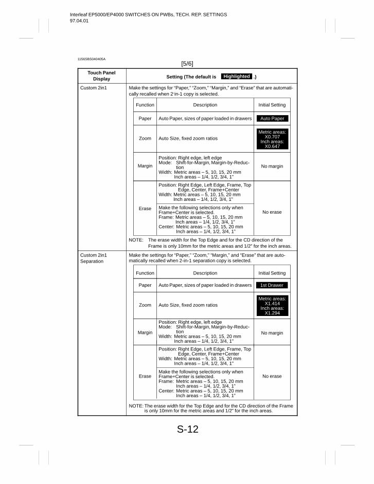
Interleaf EP5000/EP4000 SWITCHES ON PWBs, TECH. REP. SETTINGS97.04.01
S-12
1156SBS040405A
[5/6]Touch Panel
Display Setting (The default is .)Highlighted
Custom 2in1 Make the settings for “Paper,” “Zoom,” “Margin,” and “Erase” that are automati-cally recalled when 2-in-1 copy is selected.
Position: Right Edge, Left Edge, Frame, TopEdge, Center, Frame+Center
Width: Metric areas – 5, 10, 15, 20 mm Inch areas – 1/4, 1/2, 3/4, 1”
Auto Paper
Function Initial SettingDescription
Paper Auto Paper, sizes of paper loaded in drawers
Metric areas:X0.707
Inch areas:X0.647
Zoom Auto Size, fixed zoom ratios
Margin No margin
Position: Right edge, left edgeMode: Shift-for-Margin, Margin-by-Reduc-
tionWidth: Metric areas – 5, 10, 15, 20 mm
Inch areas – 1/4, 1/2, 3/4, 1”
EraseNo erase
Make the following selections only whenFrame+Center is selected.Frame: Metric areas – 5, 10, 15, 20 mm
Inch areas – 1/4, 1/2, 3/4, 1”Center: Metric areas – 5, 10, 15, 20 mm
Inch areas – 1/4, 1/2, 3/4, 1”
NOTE: The erase width for the Top Edge and for the CD direction of theFrame is only 10mm for the metric areas and 1/2” for the inch areas.
Custom 2in1Separation
Make the settings for “Paper,” “Zoom,” “Margin,” and “Erase” that are auto-matically recalled when 2-in-1 separation copy is selected.
Position: Right Edge, Left Edge, Frame, TopEdge, Center, Frame+Center
Width: Metric areas – 5, 10, 15, 20 mmInch areas – 1/4, 1/2, 3/4, 1”
Function Initial SettingDescription
Paper Auto Paper, sizes of paper loaded in drawers
Metric areas:X1.414
Inch areas:X1.294
Zoom Auto Size, fixed zoom ratios
Margin No margin
Position: Right edge, left edgeMode: Shift-for-Margin, Margin-by-Reduc-
tionWidth: Metric areas – 5, 10, 15, 20 mm
Inch areas – 1/4, 1/2, 3/4, 1”
Erase No eraseMake the following selections only whenFrame+Center is selected.Frame: Metric areas – 5, 10, 15, 20 mm
Inch areas – 1/4, 1/2, 3/4, 1”Center: Metric areas – 5, 10, 15, 20 mm
Inch areas – 1/4, 1/2, 3/4, 1”
NOTE: The erase width for the Top Edge and for the CD direction of the Frameis only 10mm for the metric areas and 1/2” for the inch areas.
1st Drawer
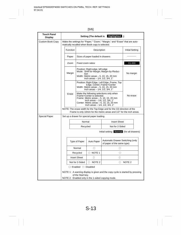
Interleaf EP5000/EP4000 SWITCHES ON PWBs, TECH. REP. SETTINGS97.04.01
S-13
[5/6]
Touch PanelDisplay Setting (The default is .)Highlighted
Custom Book Copy Make the settings for “Paper,” “Zoom,” “Margin,” and “Erase” that are auto-matically recalled when Book copy is selected.
Position: Right Edge, Left Edge, Frame, TopEdge, Center, Frame+Center
Width: Metric areas – 5, 10, 15, 20 mmInch areas – 1/4, 1/2, 3/4, 1”
Function Initial SettingDescription
Paper Sizes of paper loaded in drawers
Margin No margin
Position: Right edge, left edgeMode: Shift-for-Margin, Margin-by-Reduc-
tionWidth: Metric areas – 5, 10, 15, 20 mm
Inch areas – 1/4, 1/2, 3/4, 1”
EraseNo erase
Make the following selections only whenFrame+Center is selected.Frame: Metric areas – 5, 10, 15, 20 mm
Inch areas – 1/4, 1/2, 3/4, 1”Center: Metric areas – 5, 10, 15, 20 mm
Inch areas – 1/4, 1/2, 3/4, 1”
NOTE: The erase width for the Top Edge and for the CD direction of theFrame is only 10mm for the metric areas and 1/2” for the inch areas.
X1.000Zoom Fixed zoom ratios
Special Paper Set up a drawer for special paper loading.
NOTE 1: A warning display is given and the copy cycle is started by pressingof the Start key.
NOTE 2: Enabled only in the 1-sided copying mode.
Normal Insert Sheet
Recycled Not for 2-Sided
Auto PaperType of Paper Automatic Drawer Switching (onlyof paper of the same type)
Normal
Recycled
Insert Sheet
Not for 2-Sided
NOTE 2
NOTE 1
Initial setting: Normal (for all drawers)
NOTE 2
: Enabled : Disabled
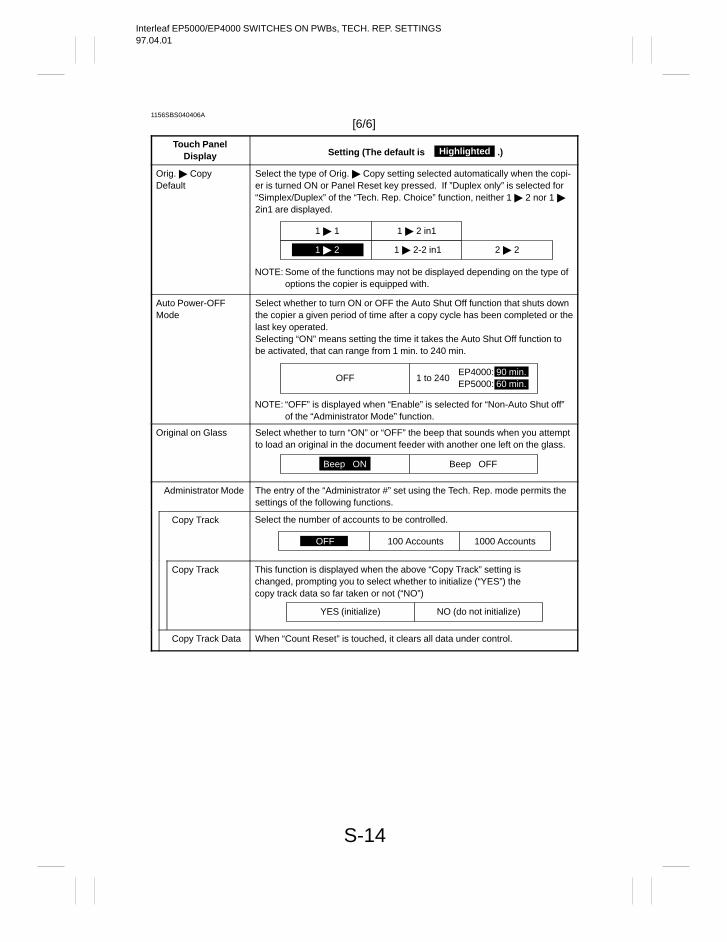
Interleaf EP5000/EP4000 SWITCHES ON PWBs, TECH. REP. SETTINGS97.04.01
S-14
1156SBS040406A
[6/6]
Touch PanelDisplay Setting (The default is .)Highlighted
Orig. CopyDefault
Select the type of Orig. Copy setting selected automatically when the copi-er is turned ON or Panel Reset key pressed. If ”Duplex only” is selected for“Simplex/Duplex” of the “Tech. Rep. Choice” function, neither 1 2 nor 1 2in1 are displayed.
NOTE: Some of the functions may not be displayed depending on the type ofoptions the copier is equipped with.
1 2
1 2 in11 1
1 2-2 in1 2 2
Auto Power-OFFMode
Select whether to turn ON or OFF the Auto Shut Off function that shuts downthe copier a given period of time after a copy cycle has been completed or thelast key operated.Selecting “ON” means setting the time it takes the Auto Shut Off function tobe activated, that can range from 1 min. to 240 min.
NOTE: “OFF” is displayed when “Enable” is selected for “Non-Auto Shut off”of the “Administrator Mode” function.
OFF 1 to 240EP4000: 90 min.EP5000: 60 min.
Original on Glass Select whether to turn “ON” or “OFF” the beep that sounds when you attemptto load an original in the document feeder with another one left on the glass.
Beep OFFBeep ON
Administrator Mode The entry of the “Administrator #” set using the Tech. Rep. mode permits thesettings of the following functions.
Copy Track
100 Accounts 1000 AccountsOFF
Select the number of accounts to be controlled.
Copy Track
YES (initialize) NO (do not initialize)
This function is displayed when the above “Copy Track” setting ischanged, prompting you to select whether to initialize (“YES”) thecopy track data so far taken or not (“NO”)
Copy Track Data When “Count Reset” is touched, it clears all data under control.
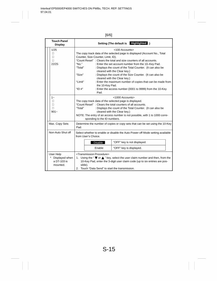
Interleaf EP5000/EP4000 SWITCHES ON PWBs, TECH. REP. SETTINGS97.04.01
S-15
[6/6]
Touch PanelDisplay Setting (The default is .)Highlighted
1/25⋅⋅⋅22/25
<100 Accounts>The copy track data of the selected page is displayed (Account No., TotalCounter, Size Counter, Limit, ID).“Count Reset” : Clears the total and size counters of all accounts.“No.” : Enter the set account number from the 10–Key Pad.“Total” : Displays the count of the Total Counter. (It can also be
cleared with the Clear key.)“Size” : Displays the count of the Size Counter. (It can also be
cleared with the Clear key.)“Limit” : Enter the maximum number of copies that can be made from
the 10-Key Pad.“ID #” : Enter the access number (0001 to 9999) from the 10-Key
Pad.
1~⋅⋅⋅901~
<1000 Accounts>The copy track data of the selected page is displayed.“Count Reset” : Clears the total counters of all accounts.“Total” : Displays the count of the Total Counter. (It can also be
cleared with the Clear key.)NOTE: The entry of an access number is not possible, with 1 to 1000 corre-
sponding to the ID numbers.
Max. Copy Sets Determine the number of copies or copy sets that can be set using the 10-KeyPad.
Non-Auto Shut off
“OFF” key is not displayed.OFF
Select whether to enable or disable the Auto Power-off Mode setting availablefrom User’s Choice.
Disable
“OFF” key is displayed.Enable
User Help* Displayed when
a DT-103 ismounted.
<Transmission Procedure>1. Using the “ or ” key, select the user claim number and then, from the
10-Key Pad, enter the 3-digit user claim code (up to six entries are pos-sible).
2. Touch “Data Send” to start the transmission.
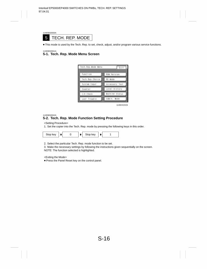
Interleaf EP5000/EP4000 SWITCHES ON PWBs, TECH. REP. SETTINGS97.04.01
S-16
1149SBS0500A
TECH. REP. MODE5 This mode is used by the Tech. Rep. to set, check, adjust, and/or program various service functions.
1149SBS0501A
5-1. Tech. Rep. Mode Menu Screen
1149O423CB
1149SBS0502A
5-2. Tech. Rep. Mode Function Setting Procedure<Setting Procedure>1. Set the copier into the Tech. Rep. mode by pressing the following keys in this order.
2. Select the particular Tech. Rep. mode function to be set.3. Make the necessary settings by following the instructions given sequentially on the screen.NOTE: The function selected is highlighted.
<Exiting the Mode> Press the Panel Reset key on the control panel.
Stop key 0 Stop key 1
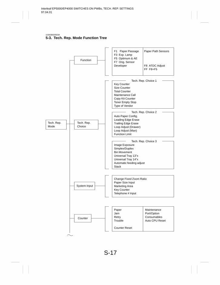
Interleaf EP5000/EP4000 SWITCHES ON PWBs, TECH. REP. SETTINGS97.04.01
S-17
1156SBS0503A
5-3. Tech. Rep. Mode Function Tree
Tech. Rep.Mode
Function
Tech. Rep.Choice
System Input
Counter
F1 Paper PassageF3 Exp. LampF5 Optimum & AEF7 Orig. SensorDeveloper
Paper Path Sensors
F8 ATDC AdjustFF F8+F5
Key CounterSize CounterTotal CounterMaintenance CallCopy Kit CounterToner Empty StopType of Vendor
Tech. Rep. Choice 1
Auto Paper Config.Leading Edge EraseTrailing Edge EraseLoop Adjust (Drawer)Loop Adjust (Man)Function Limit
Tech. Rep. Choice 2
Image ExposureSimplex/DuplexBin MovementUniversal Tray 13”xUniversal Tray 14”xAutomatic feeding adjustStack
Tech. Rep. Choice 3
Change Fixed Zoom RatioPaper Size InputMarketing AreaKey CounterTelephone # Input
PaperJamRetryTrouble
Counter Reset
MaintenancePort/OptionConsumablesAuto CPU Reset
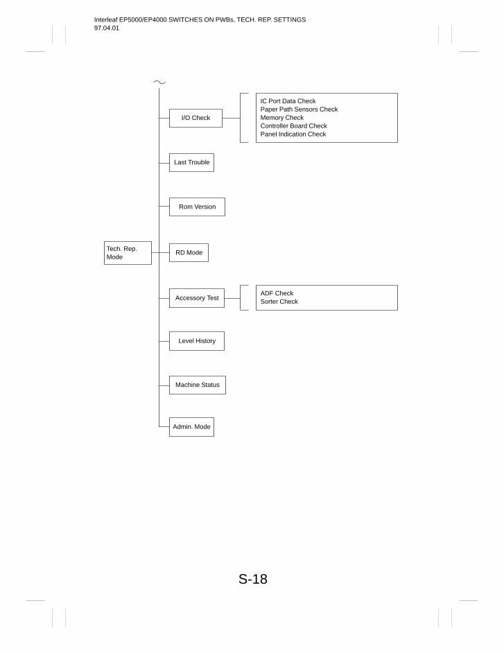
Interleaf EP5000/EP4000 SWITCHES ON PWBs, TECH. REP. SETTINGS97.04.01
S-18
Tech. Rep.Mode
I/O Check
RD Mode
Accessory Test
Level History
IC Port Data CheckPaper Path Sensors CheckMemory CheckController Board CheckPanel Indication Check
ADF CheckSorter Check
Last Trouble
Rom Version
Machine Status
Admin. Mode
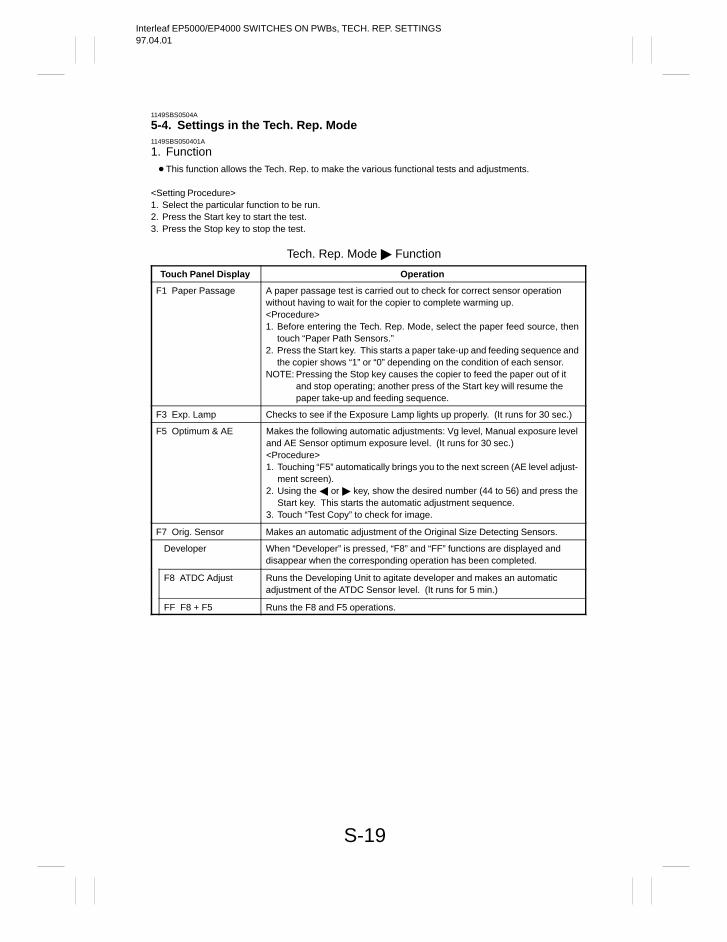
Interleaf EP5000/EP4000 SWITCHES ON PWBs, TECH. REP. SETTINGS97.04.01
S-19
1149SBS0504A
5-4. Settings in the Tech. Rep. Mode1149SBS050401A
1. Function This function allows the Tech. Rep. to make the various functional tests and adjustments.
<Setting Procedure>1. Select the particular function to be run.2. Press the Start key to start the test.3. Press the Stop key to stop the test.
Tech. Rep. Mode Function
Touch Panel Display Operation
F1 Paper Passage A paper passage test is carried out to check for correct sensor operationwithout having to wait for the copier to complete warming up.<Procedure>1. Before entering the Tech. Rep. Mode, select the paper feed source, then
touch “Paper Path Sensors.”2. Press the Start key. This starts a paper take-up and feeding sequence and
the copier shows “1” or “0” depending on the condition of each sensor.NOTE: Pressing the Stop key causes the copier to feed the paper out of it
and stop operating; another press of the Start key will resume thepaper take-up and feeding sequence.
F3 Exp. Lamp Checks to see if the Exposure Lamp lights up properly. (It runs for 30 sec.)
F5 Optimum & AE Makes the following automatic adjustments: Vg level, Manual exposure leveland AE Sensor optimum exposure level. (It runs for 30 sec.)<Procedure>1. Touching “F5” automatically brings you to the next screen (AE level adjust-
ment screen).2. Using the or key, show the desired number (44 to 56) and press the
Start key. This starts the automatic adjustment sequence.3. Touch “Test Copy” to check for image.
F7 Orig. Sensor Makes an automatic adjustment of the Original Size Detecting Sensors.
Developer When “Developer” is pressed, “F8” and “FF” functions are displayed anddisappear when the corresponding operation has been completed.
F8 ATDC Adjust Runs the Developing Unit to agitate developer and makes an automaticadjustment of the ATDC Sensor level. (It runs for 5 min.)
FF F8 + F5 Runs the F8 and F5 operations.
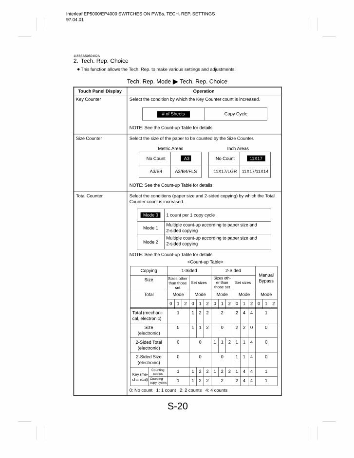
Interleaf EP5000/EP4000 SWITCHES ON PWBs, TECH. REP. SETTINGS97.04.01
S-20
1156SBS050402A
2. Tech. Rep. Choice This function allows the Tech. Rep. to make various settings and adjustments.
Tech. Rep. Mode Tech. Rep. Choice
Touch Panel Display Operation
Key Counter Select the condition by which the Key Counter count is increased.
# of Sheets Copy Cycle
NOTE: See the Count-up Table for details.
Size Counter Select the size of the paper to be counted by the Size Counter.
NOTE: See the Count-up Table for details.
No Count A3
A3/B4 A3/B4/FLS
Metric Areas
No Count 11X17
11X17/LGR 11X17/11X14
Inch Areas
Total Counter Select the conditions (paper size and 2-sided copying) by which the TotalCounter count is increased.
NOTE: See the Count-up Table for details.
Mode 0 1 count per 1 copy cycle
Mode 1Multiple count-up according to paper size and2-sided copying
Mode 2Multiple count-up according to paper size and2-sided copying
<Count-up Table>
Copying
Size
1-Sided 2-Sided
Sizes otherthan those
setSet sizes
Sizes oth-er than
those setSet sizes
Total Mode Mode Mode Mode Mode
0 1 2 0 1 2 0 1 2 0 1 2 0 1 2
ManualBypass
Total (mechani-cal, electronic)
1 2 11 2 2 2 4 4
2-Sided Total(electronic)
0 0 01 1 41 1 2
2-Sided Size(electronic)
0 0 01 1 40
Key (me-chanical)
1 2 2 2 4 41
1 2 2 1 2 2 1 4 41
2 1
1
Size(electronic)
0 0 01 1 2 2 2 0
Countingcopy cycles
Countingcopies
0: No count 1: 1 count 2: 2 counts 4: 4 counts
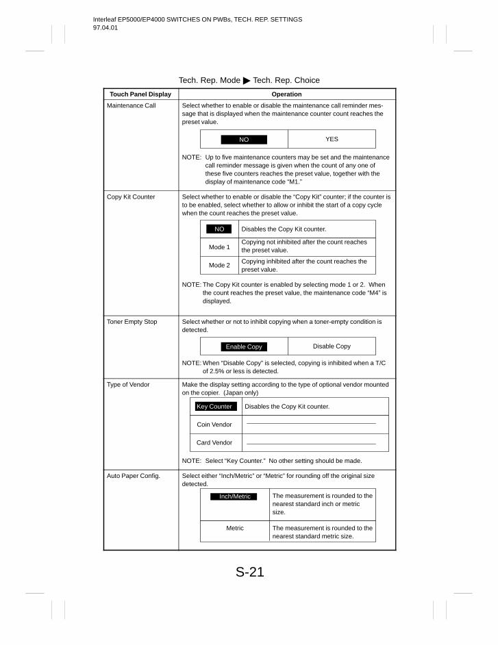
Interleaf EP5000/EP4000 SWITCHES ON PWBs, TECH. REP. SETTINGS97.04.01
S-21
Tech. Rep. Mode Tech. Rep. Choice
Touch Panel Display Operation
Maintenance Call Select whether to enable or disable the maintenance call reminder mes-sage that is displayed when the maintenance counter count reaches thepreset value.
NO YES
NOTE: Up to five maintenance counters may be set and the maintenancecall reminder message is given when the count of any one ofthese five counters reaches the preset value, together with thedisplay of maintenance code “M1.”
Copy Kit Counter Select whether to enable or disable the “Copy Kit” counter; if the counter isto be enabled, select whether to allow or inhibit the start of a copy cyclewhen the count reaches the preset value.
NOTE: The Copy Kit counter is enabled by selecting mode 1 or 2. Whenthe count reaches the preset value, the maintenance code “M4” isdisplayed.
NO Disables the Copy Kit counter.
Mode 1Copying not inhibited after the count reachesthe preset value.
Mode 2Copying inhibited after the count reaches thepreset value.
Toner Empty Stop Select whether or not to inhibit copying when a toner-empty condition isdetected.
Enable Copy Disable Copy
NOTE: When “Disable Copy” is selected, copying is inhibited when a T/Cof 2.5% or less is detected.
Type of Vendor
NOTE: Select “Key Counter.” No other setting should be made.
Make the display setting according to the type of optional vendor mountedon the copier. (Japan only)
Key Counter Disables the Copy Kit counter.
Coin Vendor
Card Vendor
Auto Paper Config. Select either “Inch/Metric” or “Metric” for rounding off the original sizedetected.
Inch/Metric The measurement is rounded to thenearest standard inch or metricsize.
Metric The measurement is rounded to thenearest standard metric size.
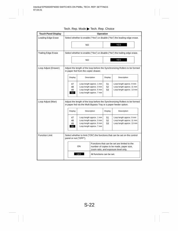
Interleaf EP5000/EP4000 SWITCHES ON PWBs, TECH. REP. SETTINGS97.04.01
S-22
Tech. Rep. Mode Tech. Rep. Choice
Touch Panel Display Operation
Leading Edge Erase Select whether to enable (“Yes”) or disable (“No”) the leading edge erase.
NO YES
Trailing Edge Erase Select whether to enable (“Yes”) or disable (“No”) the trailing edge erase.
NO YES
Loop Adjust (Drawer) Adjust the length of the loop before the Synchronizing Rollers to be formedin paper fed from the copier drawer.
Display
Description
47484950
Loop length approx. 1 mm
Loop length approx. 3 mm
Loop length approx. 5 mm
Loop length approx. 7 mm
Display
Description
515253
Loop length approx. 9 mm
Loop length approx. 11 mm
Loop length approx. 13 mm
Loop Adjust (Man) Adjust the length of the loop before the Synchronizing Rollers to be formedin paper fed via the Multi Bypass Tray or a paper feeder option.
Display
Description
47484950
Loop length approx. 1 mm
Loop length approx. 3 mm
Loop length approx. 5 mm
Loop length approx. 7 mm
Display
Description
515253
Loop length approx. 9 mm
Loop length approx. 11 mm
Loop length approx. 13 mm
Function Limit Select whether to limit (“ON”) the functions that can be set on the controlpanel or not (“OFF”).
ONFunctions that can be set are limited to thenumber of copies to be made, paper size,zoom ratio, and exposure level only.
OFF All functions can be set.
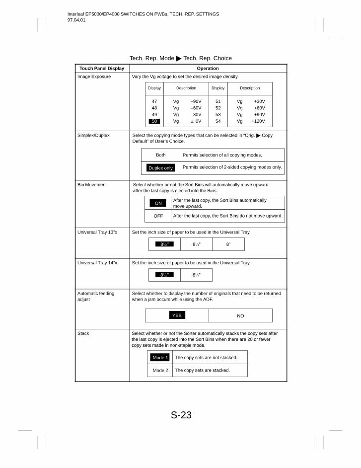
Interleaf EP5000/EP4000 SWITCHES ON PWBs, TECH. REP. SETTINGS97.04.01
S-23
Tech. Rep. Mode Tech. Rep. Choice
Touch Panel Display Operation
Image Exposure Vary the Vg voltage to set the desired image density.
Display
Description
47484950
Vg –90VVg –60VVg –30VVg 0V
Display
Description
51525354
Vg +30VVg +60VVg +90VVg +120V
Simplex/Duplex Select the copying mode types that can be selected in “Orig. CopyDefault” of User’s Choice.
Both Permits selection of all copying modes.
Duplex only Permits selection of 2-sided copying modes only.
Bin Movement Select whether or not the Sort Bins will automatically move upwardafter the last copy is ejected into the Bins.
OFF
After the last copy, the Sort Bins automaticallymove upward.
ON
After the last copy, the Sort Bins do not move upward.
Universal Tray 13”x Set the inch size of paper to be used in the Universal Tray.
8 8” 8”
Universal Tray 14”x Set the inch size of paper to be used in the Universal Tray.
8 8”
Automatic feeding adjust
Select whether to display the number of originals that need to be returnedwhen a jam occurs while using the ADF.
NOYES
Stack Select whether or not the Sorter automatically stacks the copy sets afterthe last copy is ejected into the Sort Bins when there are 20 or fewercopy sets made in non-staple mode.
Mode 2
The copy sets are not stacked.Mode 1
The copy sets are stacked.
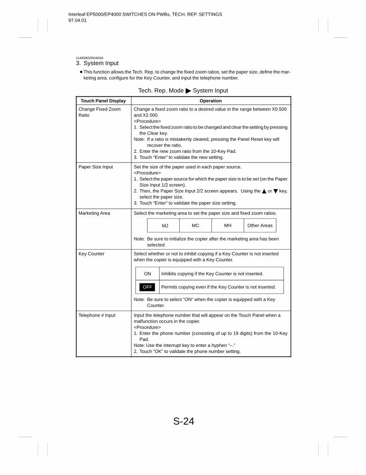
Interleaf EP5000/EP4000 SWITCHES ON PWBs, TECH. REP. SETTINGS97.04.01
S-24
1149SBS050403A
3. System Input This function allows the Tech. Rep. to change the fixed zoom ratios, set the paper size, define the mar-
keting area, configure for the Key Counter, and input the telephone number.
Tech. Rep. Mode System Input
Touch Panel Display Operation
Change Fixed ZoomRatio
Change a fixed zoom ratio to a desired value in the range between X0.500and X2.000.<Procedure>1. Select the fixed zoom ratio to be changed and clear the setting by pressing
the Clear key.Note: If a ratio is mistakenly cleared, pressing the Panel Reset key will
recover the ratio.2. Enter the new zoom ratio from the 10-Key Pad.3. Touch “Enter” to validate the new setting.
Paper Size Input Set the size of the paper used in each paper source.<Procedure>1. Select the paper source for which the paper size is to be set (on the Paper
Size Input 1/2 screen).2. Then, the Paper Size Input 2/2 screen appears. Using the or key,
select the paper size.3. Touch “Enter” to validate the paper size setting.
Marketing Area Select the marketing area to set the paper size and fixed zoom ratios.
MJ MC MH Other Areas
Note: Be sure to initialize the copier after the marketing area has beenselected.
Key Counter Select whether or not to inhibit copying if a Key Counter is not insertedwhen the copier is equipped with a Key Counter.
Note: Be sure to select “ON” when the copier is equipped with a KeyCounter.
ON Inhibits copying if the Key Counter is not inserted.
Permits copying even if the Key Counter is not inserted.OFF
Telephone # Input Input the telephone number that will appear on the Touch Panel when amalfunction occurs in the copier.<Procedure>1. Enter the phone number (consisting of up to 19 digits) from the 10-Key
Pad.Note: Use the Interrupt key to enter a hyphen “–.”2. Touch “OK” to validate the phone number setting.
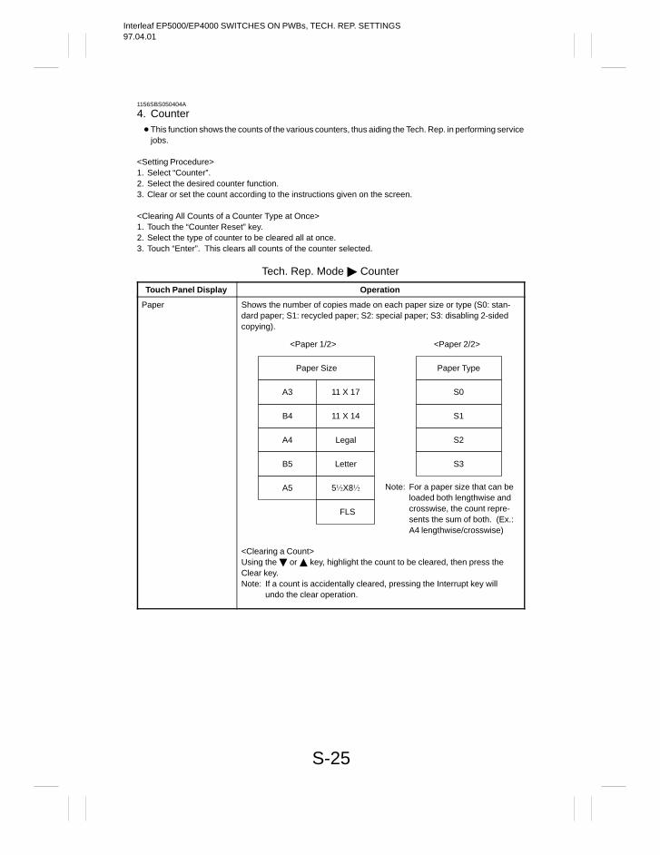
Interleaf EP5000/EP4000 SWITCHES ON PWBs, TECH. REP. SETTINGS97.04.01
S-25
1156SBS050404A
4. Counter This function shows the counts of the various counters, thus aiding the Tech. Rep. in performing service
jobs.
<Setting Procedure>1. Select “Counter”.2. Select the desired counter function.3. Clear or set the count according to the instructions given on the screen.
<Clearing All Counts of a Counter Type at Once>1. Touch the “Counter Reset” key.2. Select the type of counter to be cleared all at once.3. Touch “Enter”. This clears all counts of the counter selected.
Tech. Rep. Mode Counter
Touch Panel Display Operation
Paper Shows the number of copies made on each paper size or type (S0: stan-dard paper; S1: recycled paper; S2: special paper; S3: disabling 2-sidedcopying).
<Paper 1/2>
Paper Size
A3 11 X 17
B4 11 X 14
A4 Legal
B5 Letter
A5 5X8
FLS
Paper Type
S0
S1
S2
S3
<Paper 2/2>
Note: For a paper size that can beloaded both lengthwise andcrosswise, the count repre-sents the sum of both. (Ex.:A4 lengthwise/crosswise)
<Clearing a Count>Using the or key, highlight the count to be cleared, then press theClear key.Note: If a count is accidentally cleared, pressing the Interrupt key will
undo the clear operation.
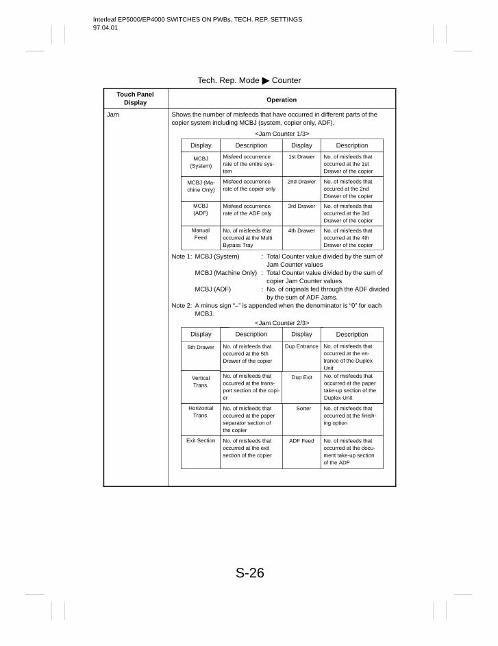
Interleaf EP5000/EP4000 SWITCHES ON PWBs, TECH. REP. SETTINGS97.04.01
S-26
Tech. Rep. Mode Counter
Touch PanelDisplay Operation
Jam Shows the number of misfeeds that have occurred in different parts of thecopier system including MCBJ (system, copier only, ADF).
<Jam Counter 1/3>
Display Description Display Description
MCBJ(System)
Misfeed occurrencerate of the entire sys-tem
1st Drawer No. of misfeeds thatoccurred at the 1stDrawer of the copier
MCBJ (Ma-chine Only)
Misfeed occurrencerate of the copier only
2nd Drawer No. of misfeeds thatoccured at the 2ndDrawer of the copier
MCBJ(ADF)
Misfeed occurrencerate of the ADF only
3rd Drawer No. of misfeeds thatoccurred at the 3rdDrawer of the copier
ManualFeed
No. of misfeeds thatoccurred at the MultiBypass Tray
4th Drawer No. of misfeeds thatoccurred at the 4thDrawer of the copier
Note 1: MCBJ (System)
MCBJ (Machine Only)
MCBJ (ADF)
Note 2: A minus sign “–” is appended when the denominator is “0” for eachMCBJ.
: Total Counter value divided by the sum ofJam Counter values
: Total Counter value divided by the sum ofcopier Jam Counter values
: No. of originals fed through the ADF dividedby the sum of ADF Jams.
<Jam Counter 2/3>
Display Description Display Description
5th Drawer No. of misfeeds thatoccurred at the 5thDrawer of the copier
Dup Entrance No. of misfeeds thatoccurred at the en-trance of the DuplexUnit
VerticalTrans.
No. of misfeeds thatoccurred at the trans-port section of the copi-er
Dup Exit No. of misfeeds thatoccurred at the papertake-up section of theDuplex Unit
HorizontalTrans.
No. of misfeeds thatoccurred at the paperseparator section ofthe copier
Sorter No. of misfeeds thatoccurred at the finish-ing option
Exit Section No. of misfeeds thatoccurred at the exitsection of the copier
ADF Feed No. of misfeeds thatoccurred at the docu-ment take-up sectionof the ADF
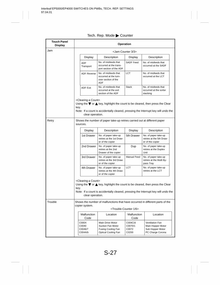
Interleaf EP5000/EP4000 SWITCHES ON PWBs, TECH. REP. SETTINGS97.04.01
S-27
Tech. Rep. Mode Counter
Touch PanelDisplay Operation
Jam <Jam Counter 3/3>
Display Description Display Description
ADFTransport
No. of misfeeds thatoccurred at the trans-port section of the ADF
ADF Reverse No. of misfeeds thatoccurred at the turn-over section of theADF
SADF Feed No. of misfeeds thatoccurred at the SADF
<Clearing a Count>Using the or key, highlight the count to be cleared, then press the Clearkey.Note: If a count is accidentally cleared, pressing the Interrupt key will undo the
clear operation.
ADF Exit No. of misfeeds thatoccurred at the exitsection of the ADF
Stack No. of misfeeds thatoccurred at the sorterstacking
LCT No. of misfeeds thatoccurred at the LCT
Retry
<Clearing a Count>Using the or key, highlight the count to be cleared, then press the Clearkey.Note: If a count is accidentally cleared, pressing the Interrupt key will undo the
clear operation.
Display Description Display Description
1st Drawer No. of paper take-upretries at the 1st Draw-er of the copier
5th Drawer No. of paper take-upretries at the 5th Draw-er of the copier
2nd Drawer No. of paper take-upretries at the 2ndDrawer of the copier
Dup No. of paper take-upretries at the DuplexUnit
3rd Drawer No. of paper take-upretries at the 3rd Draw-er of the copier
Manual Feed No. of paper take-upretries at the Multi By-pass Tray
Shows the number of paper take-up retries carried out at different papersources.
4th Drawer No. of paper take-upretries at the 4th Draw-er of the copier
LCT No. of paper take-upretries at the LCT
Trouble
<Trouble Counter 1/6>
Shows the number of malfunctions that have occurred in different parts of thecopier system.
MalfunctionCode
Location MalfunctionCode
Location
C000XC0040C0046/7C004A/b
Main Drive MotorSuction Fan MotorFusing Cooling FanOptical Cooling Fan
C004C/dC0070/1C0072C0200
Ventilation FanMain Hopper MotorSub Hopper MotorPC Charge Corona
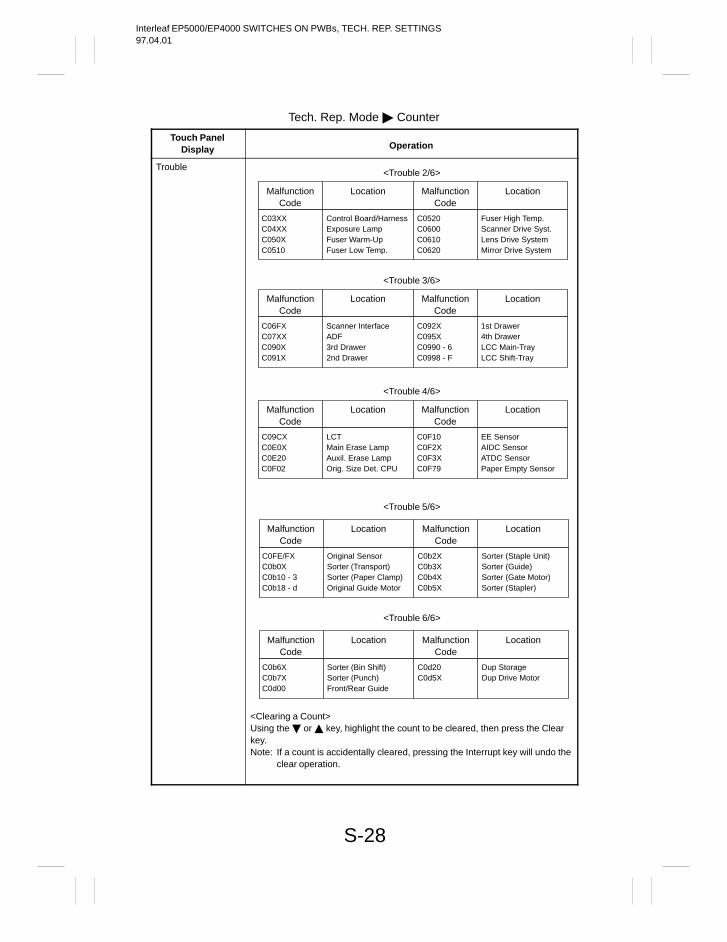
Interleaf EP5000/EP4000 SWITCHES ON PWBs, TECH. REP. SETTINGS97.04.01
S-28
Tech. Rep. Mode Counter
Touch PanelDisplay Operation
Trouble<Trouble 2/6>
MalfunctionCode
Location MalfunctionCode
Location
C03XXC04XXC050XC0510
Control Board/HarnessExposure LampFuser Warm-UpFuser Low Temp.
C0520C0600C0610C0620
Fuser High Temp.Scanner Drive Syst.Lens Drive SystemMirror Drive System
<Trouble 3/6>
MalfunctionCode
Location MalfunctionCode
Location
C06FXC07XXC090XC091X
Scanner InterfaceADF3rd Drawer2nd Drawer
C092XC095XC0990 - 6C0998 - F
1st Drawer4th DrawerLCC Main-TrayLCC Shift-Tray
<Trouble 4/6>
MalfunctionCode
Location MalfunctionCode
Location
C09CXC0E0XC0E20C0F02
LCTMain Erase LampAuxil. Erase LampOrig. Size Det. CPU
C0F10C0F2XC0F3XC0F79
EE SensorAIDC SensorATDC SensorPaper Empty Sensor
<Trouble 5/6>
<Clearing a Count>Using the or key, highlight the count to be cleared, then press the Clearkey.Note: If a count is accidentally cleared, pressing the Interrupt key will undo the
clear operation.
MalfunctionCode
Location MalfunctionCode
Location
C0FE/FXC0b0XC0b10 - 3C0b18 - d
Original SensorSorter (Transport)Sorter (Paper Clamp)Original Guide Motor
C0b2XC0b3XC0b4XC0b5X
Sorter (Staple Unit)Sorter (Guide)Sorter (Gate Motor)Sorter (Stapler)
<Trouble 6/6>
MalfunctionCode
Location MalfunctionCode
Location
C0b6XC0b7XC0d00
Sorter (Bin Shift)Sorter (Punch)Front/Rear Guide
C0d20C0d5X
Dup StorageDup Drive Motor
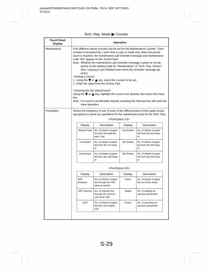
Interleaf EP5000/EP4000 SWITCHES ON PWBs, TECH. REP. SETTINGS97.04.01
S-29
Tech. Rep. Mode Counter
Touch PanelDisplay Operation
Maintenance Five different values (counts) can be set for the Maintenance Counter. Eachcounter is increased by 1 each time a copy is made and, when the presetcount is reached, the maintenance call reminder message and maintenancecode “M1” appear on the Touch Panel.Note: Whether the maintenance call reminder message is given or not de-
pends on the setting made for “Maintenance” of “Tech. Rep. Choice.”Also, copying is not inhibited even when the reminder message ap-pears.
<Setting a Count>1. Using the or key, select the counter to be set.2. Enter the value from the 10-Key Pad.
<Clearing the Set Value/Count>Using the or key, highlight the count to be cleared, then press the Clearkey.Note: If a count is accidentally cleared, pressing the Interrupt key will undo the
clear operation.
Port/option Shows the frequency of use of each of the different parts of the copier includ-ing options to serve as a guideline for the maintenance time for the Tech. Rep.
<Port/Option 1/3>
Display Description Display Description
Manual Feed No. of sheets of paperfed from the Multi By-pass Tray
3rd Drawer No. of sheets of paperfed from the 3rd Draw-er
1st Drawer No. of sheets of paperfed from the 1st Draw-er
4th Drawer No. of sheets of paperfed from the 4th Draw-er
2nd Drawer No. of sheets of paperfed from the 2nd Draw-er
5th Drawer No. of sheets of paperfed from the 5th Draw-er
<Port/Option 2/3>
Display Description Display Description
ADFEntrance
No. of sheets of paperfed through the ADFtake-up section.
Sorter No. of sheets of paperfed out of the Sorter
ADF Reverse No. of originals fedthrough the turnoverunit of the ADF
Staple No. of stapling se-quences performed
DUP No. of sheets of paperfed from the DuplexUnit
Punch No. of punching se-quences performed
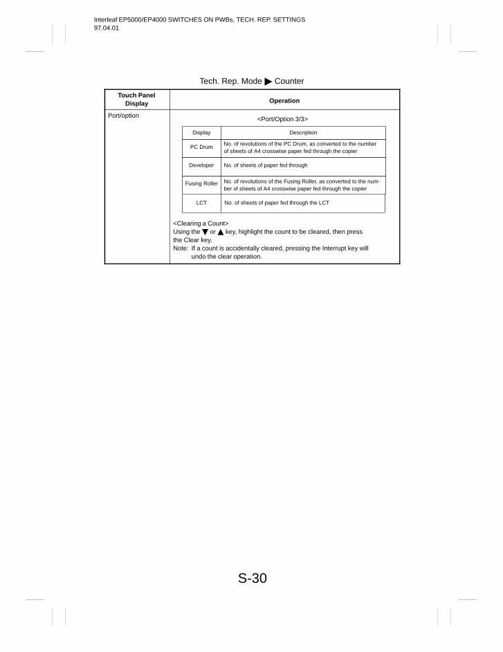
Interleaf EP5000/EP4000 SWITCHES ON PWBs, TECH. REP. SETTINGS97.04.01
S-30
Tech. Rep. Mode Counter
Touch PanelDisplay Operation
Port/option <Port/Option 3/3>
Display Description
PC Drum No. of revolutions of the PC Drum, as converted to the numberof sheets of A4 crosswise paper fed through the copier
Developer No. of sheets of paper fed through
Fusing Roller No. of revolutions of the Fusing Roller, as converted to the num-ber of sheets of A4 crosswise paper fed through the copier
<Clearing a Count>Using the or key, highlight the count to be cleared, then pressthe Clear key.Note: If a count is accidentally cleared, pressing the Interrupt key will
undo the clear operation.
LCT No. of sheets of paper fed through the LCT
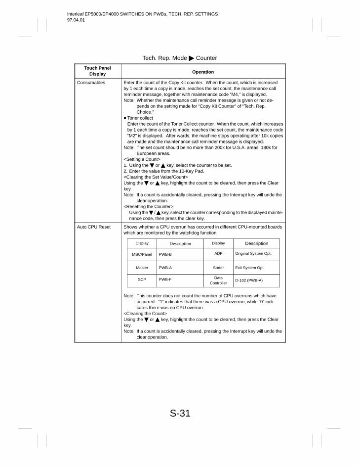
Interleaf EP5000/EP4000 SWITCHES ON PWBs, TECH. REP. SETTINGS97.04.01
S-31
Tech. Rep. Mode Counter
Touch PanelDisplay Operation
Consumables Enter the count of the Copy Kit counter. When the count, which is increasedby 1 each time a copy is made, reaches the set count, the maintenance callreminder message, together with maintenance code “M4,” is displayed.Note: Whether the maintenance call reminder message is given or not de-
pends on the setting made for “Copy Kit Counter” of “Tech. Rep.Choice.”
Toner collectEnter the count of the Toner Collect counter. When the count, which increasesby 1 each time a copy is made, reaches the set count, the maintenance code“M2” is displayed. After wards, the machine stops operating after 10k copiesare made and the maintenance call reminder message is displayed.
Note: The set count should be no more than 200k for U.S.A. areas, 180k forEuropean areas.
<Setting a Count>1. Using the or key, select the counter to be set.2. Enter the value from the 10-Key Pad.<Clearing the Set Value/Count>Using the or key, highlight the count to be cleared, then press the Clearkey.Note: If a count is accidentally cleared, pressing the Interrupt key will undo the
clear operation.<Resetting the Counter>
Using the / key, select the counter corresponding to the displayed mainte-nance code, then press the clear key.
Auto CPU Reset Shows whether a CPU overrun has occurred in different CPU-mounted boardswhich are monitored by the watchdog function.
Display Description Display Description
MSC/Panel PWB-B ADF Original System Opt.
Master PWB-A Sorter Exit System Opt.
SCP PWB-F DataController
D-102 (PWB-A)
Note: This counter does not count the number of CPU overruns which haveoccurred. “1” indicates that there was a CPU overrun, while “0” indi-cates there was no CPU overrun.
<Clearing the Count>Using the or key, highlight the count to be cleared, then press the Clearkey.Note: If a count is accidentally cleared, pressing the Interrupt key will undo the
clear operation.
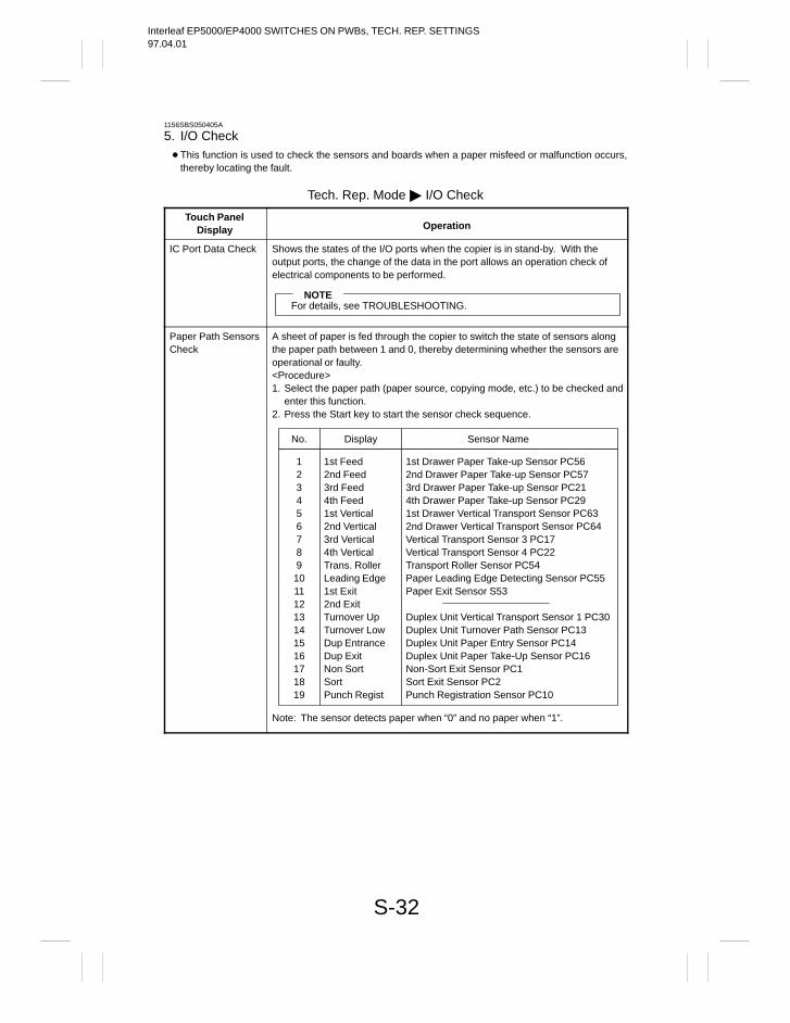
Interleaf EP5000/EP4000 SWITCHES ON PWBs, TECH. REP. SETTINGS97.04.01
S-32
1156SBS050405A
5. I/O Check This function is used to check the sensors and boards when a paper misfeed or malfunction occurs,
thereby locating the fault.
Tech. Rep. Mode I/O Check
Touch PanelDisplay Operation
IC Port Data Check Shows the states of the I/O ports when the copier is in stand-by. With theoutput ports, the change of the data in the port allows an operation check ofelectrical components to be performed.
NOTEFor details, see TROUBLESHOOTING.
Paper Path SensorsCheck
A sheet of paper is fed through the copier to switch the state of sensors alongthe paper path between 1 and 0, thereby determining whether the sensors areoperational or faulty.<Procedure>1. Select the paper path (paper source, copying mode, etc.) to be checked and
enter this function.2. Press the Start key to start the sensor check sequence.
No. Display Sensor Name
12345678910111213141516171819
1st Feed2nd Feed3rd Feed4th Feed1st Vertical2nd Vertical3rd Vertical4th VerticalTrans. RollerLeading Edge1st Exit2nd ExitTurnover UpTurnover LowDup EntranceDup ExitNon SortSortPunch Regist
1st Drawer Paper Take-up Sensor PC562nd Drawer Paper Take-up Sensor PC573rd Drawer Paper Take-up Sensor PC214th Drawer Paper Take-up Sensor PC291st Drawer Vertical Transport Sensor PC632nd Drawer Vertical Transport Sensor PC64Vertical Transport Sensor 3 PC17Vertical Transport Sensor 4 PC22Transport Roller Sensor PC54Paper Leading Edge Detecting Sensor PC55Paper Exit Sensor S53
Duplex Unit Vertical Transport Sensor 1 PC30Duplex Unit Turnover Path Sensor PC13Duplex Unit Paper Entry Sensor PC14Duplex Unit Paper Take-Up Sensor PC16Non-Sort Exit Sensor PC1Sort Exit Sensor PC2Punch Registration Sensor PC10
Note: The sensor detects paper when “0” and no paper when “1”.
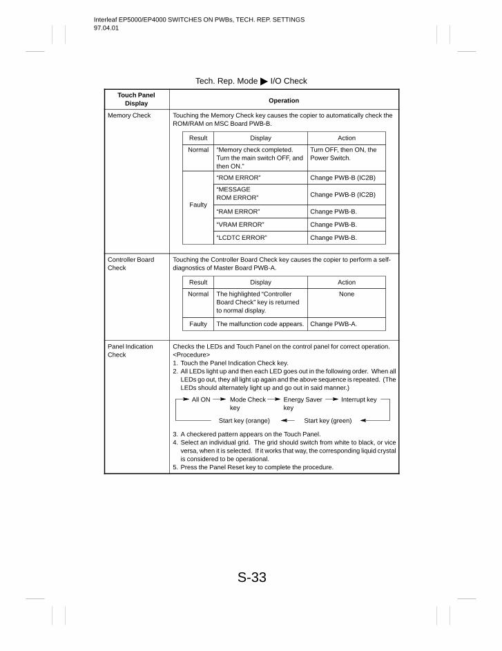
Interleaf EP5000/EP4000 SWITCHES ON PWBs, TECH. REP. SETTINGS97.04.01
S-33
Tech. Rep. Mode I/O Check
Touch PanelDisplay Operation
Memory Check Touching the Memory Check key causes the copier to automatically check theROM/RAM on MSC Board PWB-B.
Result Display Action
Normal “Memory check completed.Turn the main switch OFF, andthen ON.”
Turn OFF, then ON, thePower Switch.
Faulty
“ROM ERROR” Change PWB-B (IC2B)
“MESSAGEROM ERROR” Change PWB-B (IC2B)
“RAM ERROR” Change PWB-B.
“VRAM ERROR” Change PWB-B.
“LCDTC ERROR” Change PWB-B.
Controller BoardCheck
Touching the Controller Board Check key causes the copier to perform a self-diagnostics of Master Board PWB-A.
Result Display Action
Normal The highlighted “ControllerBoard Check” key is returnedto normal display.
None
Faulty The malfunction code appears. Change PWB-A.
Panel IndicationCheck
Checks the LEDs and Touch Panel on the control panel for correct operation.<Procedure>1. Touch the Panel Indication Check key.2. All LEDs light up and then each LED goes out in the following order. When all
LEDs go out, they all light up again and the above sequence is repeated. (TheLEDs should alternately light up and go out in said manner.)
All ON Mode Checkkey
Interrupt keyEnergy Saverkey
Start key (green)Start key (orange)
3. A checkered pattern appears on the Touch Panel.4. Select an individual grid. The grid should switch from white to black, or vice
versa, when it is selected. If it works that way, the corresponding liquid crystalis considered to be operational.
5. Press the Panel Reset key to complete the procedure.
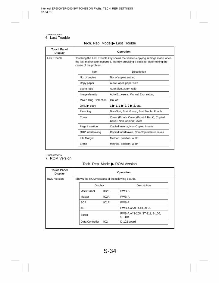
Interleaf EP5000/EP4000 SWITCHES ON PWBs, TECH. REP. SETTINGS97.04.01
S-34
1149SBS050406A
6. Last Trouble
Tech. Rep. Mode Last Trouble
Touch PanelDisplay Operation
Last Trouble Touching the Last Trouble key shows the various copying settings made whenthe last malfunction occurred, thereby providing a basis for determining thecause of the problem.
Item Description
No. of copies settingNo. of copies
Auto Paper, paper sizeCopy paper
Auto Size, zoom ratioZoom ratio
Auto Exposure, Manual Exp. settingImage density
On, offMixed Orig. Detection
1 1, 1 2, 2 2, etc.Orig. copy
Non-Sort, Sort, Group, Sort Staple, PunchFinishing
Cover (Front), Cover (Front & Back), CopiedCover, Non-Copied Cover
Cover
Copied Inserts, Non-Copied InsertsPage Insertion
Copied Interleaves, Non-Copied InterleavesOHP Interleaving
Method, position, widthFile Margin
Method, position, widthErase
1156SBS050407A
7. ROM Version
Tech. Rep. Mode ROM Version
Touch PanelDisplay Operation
ROM Version Shows the ROM versions of the following boards.
Display Description
PWB-BMSC/Panel IC2B
PWB-AMaster IC2A
PWB-FSCP IC1F
PWB-A of AFR-13, AF-5ADF
PWB-A of S-208, ST-211, S-106,ST-104
Sorter
D-102 boardData Controller IC2
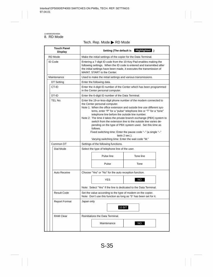
Interleaf EP5000/EP4000 SWITCHES ON PWBs, TECH. REP. SETTINGS97.04.01
S-35
1149SBS050408A
8. RD Mode
Tech. Rep. Mode RD Mode
Touch PanelDisplay Setting (The default is .)Highlighted
RD Mode Make the initial settings of the copier for the Data Terminal.
ID Code Entering a 7-digit ID code from the 10-Key Pad enables making thefollowing settings. When the ID code is entered and transmitted afterthe initial settings have been made, it executes the transmission ofMAINT. START to the Center.
Maintenance Used to make the initial settings and various transmissions.
DT Setting Enter the following data.
CT-ID Enter the 4-digit ID number of the Center which has been programmedin the Center personal computer.
DT-ID Enter the 6-digit ID number of the Data Terminal.
TEL No. Enter the 19-or-less-digit phone number of the modem connected tothe Center personal computer.Note 1: When the office extension and outside line use different sys-
tems, enter “P” for a “pulse” telephone line or “T” for a “tone”telephone line before the outside line number.
Note 2: The time it takes the private branch exchange (PBX) system toswitch from the extension line to the outside line varies de-pending on the type of PBX system used. Set this time asfollows.
Fixed switching time: Enter the pause code “–” (a single “–”lasts 2 sec.).
Varying switching time: Enter the wait code “W.”
Common DT Settings of the following functions.
Dial Mode Select the type of telephone line of the user.
Tone linePulse line
TonePulse
Auto Receive Choose “Yes” or “No” for the auto reception function.
YES NO
Note: Select “Yes” if the line is dedicated to the Data Terminal.
Result Code Set the value according to the type of modem on the copier.Note: Don’t use this function as long as “5” has been set for it.
Report Format Japan only
10 BIT
RAM Clear Reinitializes the Data Terminal.
Maintenance NO
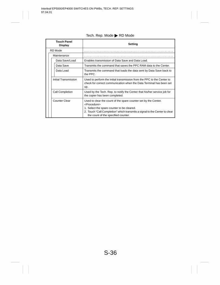
Interleaf EP5000/EP4000 SWITCHES ON PWBs, TECH. REP. SETTINGS97.04.01
S-36
Tech. Rep. Mode RD Mode
Touch PanelDisplay Setting
RD Mode . . . . . . . . . . . . . . . . . . . . . . . . . . . . . . . . . . . . . . . . . . . . . . . . . . . . . . . . . . . . . . .
Maintenance . . . . . . . . . . . . . . . . . . . . . . . . . . . . . . . . . . . . . . . . . . . . . . . . . . . . . . . . . . . . . . .
Data Save/Load Enables transmission of Data Save and Data Load.
Data Save Transmits the command that saves the PPC RAM data to the Center.
Data Load Transmits the command that loads the data sent by Data Save back tothe PPC.
Initial Transmission Used to perform the initial transmission from the PPC to the Center tocheck for correct communication when the Data Terminal has been setup.
Call Completion Used by the Tech. Rep. to notify the Center that his/her service job forthe copier has been completed.
Counter Clear Used to clear the count of the spare counter set by the Center.<Procedure>1. Select the spare counter to be cleared.2. Touch “Call Completion” which transmits a signal to the Center to clear
the count of the specified counter.
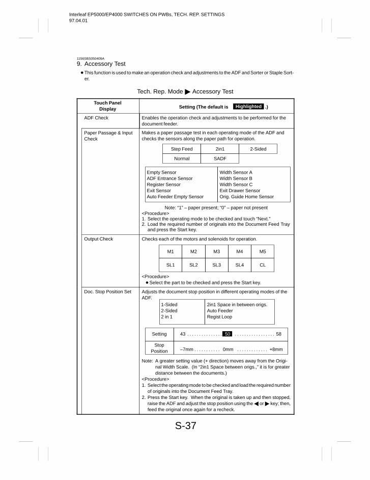
Interleaf EP5000/EP4000 SWITCHES ON PWBs, TECH. REP. SETTINGS97.04.01
S-37
1156SBS050409A
9. Accessory Test This function is used to make an operation check and adjustments to the ADF and Sorter or Staple Sort-
er.
Tech. Rep. Mode Accessory Test
Touch PanelDisplay Setting (The default is .)Highlighted
ADF Check Enables the operation check and adjustments to be performed for thedocument feeder.
Paper Passage & InputCheck
Makes a paper passage test in each operating mode of the ADF andchecks the sensors along the paper path for operation.
2in1 2-SidedStep Feed
SADFNormal
Empty SensorADF Entrance SensorRegister SensorExit SensorAuto Feeder Empty Sensor
Width Sensor AWidth Sensor BWidth Sensor CExit Drawer SensorOrig. Guide Home Sensor
Note: “1” – paper present; “0” – paper not present<Procedure>1. Select the operating mode to be checked and touch “Next.”2. Load the required number of originals into the Document Feed Tray
and press the Start key.
Output Check Checks each of the motors and solenoids for operation.
M1 M2 M3 M4 M5
SL1 SL2 SL3 SL4 CL
<Procedure> Select the part to be checked and press the Start key.
Doc. Stop Position Set Adjusts the document stop position in different operating modes of theADF.
Setting 43 50 58. . . . . . . . . . . . . . . . . . . . . . . . . . . . . . . .
1-Sided2-Sided2 in 1
2in1 Space in between origs.Auto FeederRegist Loop
StopPosition –7mm 0mm +8mm. . . . . . . . . . . . . . . . . . . . . . . .
Note: A greater setting value (+ direction) moves away from the Origi-nal Width Scale. (In “2in1 Space between origs.,” it is for greaterdistance between the documents.)
<Procedure>1. Select the operating mode to be checked and load the required number
of originals into the Document Feed Tray.2. Press the Start key. When the original is taken up and then stopped,
raise the ADF and adjust the stop position using the or key; then,feed the original once again for a recheck.
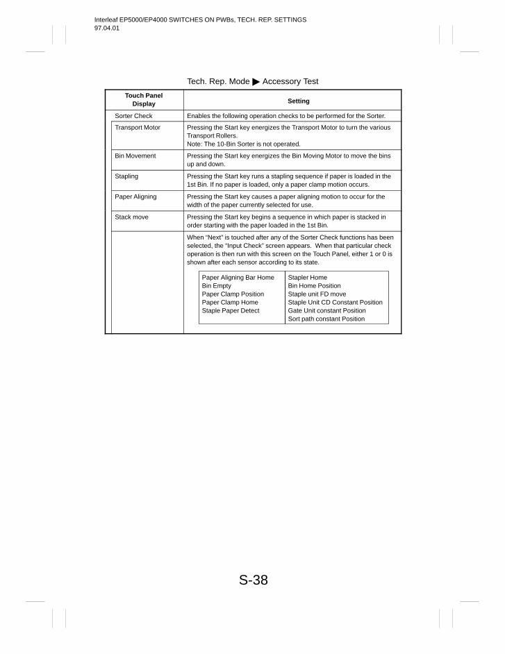
Interleaf EP5000/EP4000 SWITCHES ON PWBs, TECH. REP. SETTINGS97.04.01
S-38
Tech. Rep. Mode Accessory Test
Touch PanelDisplay Setting
Sorter Check Enables the following operation checks to be performed for the Sorter.
Transport Motor Pressing the Start key energizes the Transport Motor to turn the variousTransport Rollers.Note: The 10-Bin Sorter is not operated.
Bin Movement Pressing the Start key energizes the Bin Moving Motor to move the binsup and down.
Stapling Pressing the Start key runs a stapling sequence if paper is loaded in the1st Bin. If no paper is loaded, only a paper clamp motion occurs.
Paper Aligning Pressing the Start key causes a paper aligning motion to occur for thewidth of the paper currently selected for use.
Stack move Pressing the Start key begins a sequence in which paper is stacked inorder starting with the paper loaded in the 1st Bin.
When “Next” is touched after any of the Sorter Check functions has beenselected, the “Input Check” screen appears. When that particular checkoperation is then run with this screen on the Touch Panel, either 1 or 0 isshown after each sensor according to its state.
Paper Aligning Bar HomeBin EmptyPaper Clamp PositionPaper Clamp HomeStaple Paper Detect
Stapler HomeBin Home PositionStaple unit FD moveStaple Unit CD Constant PositionGate Unit constant PositionSort path constant Position
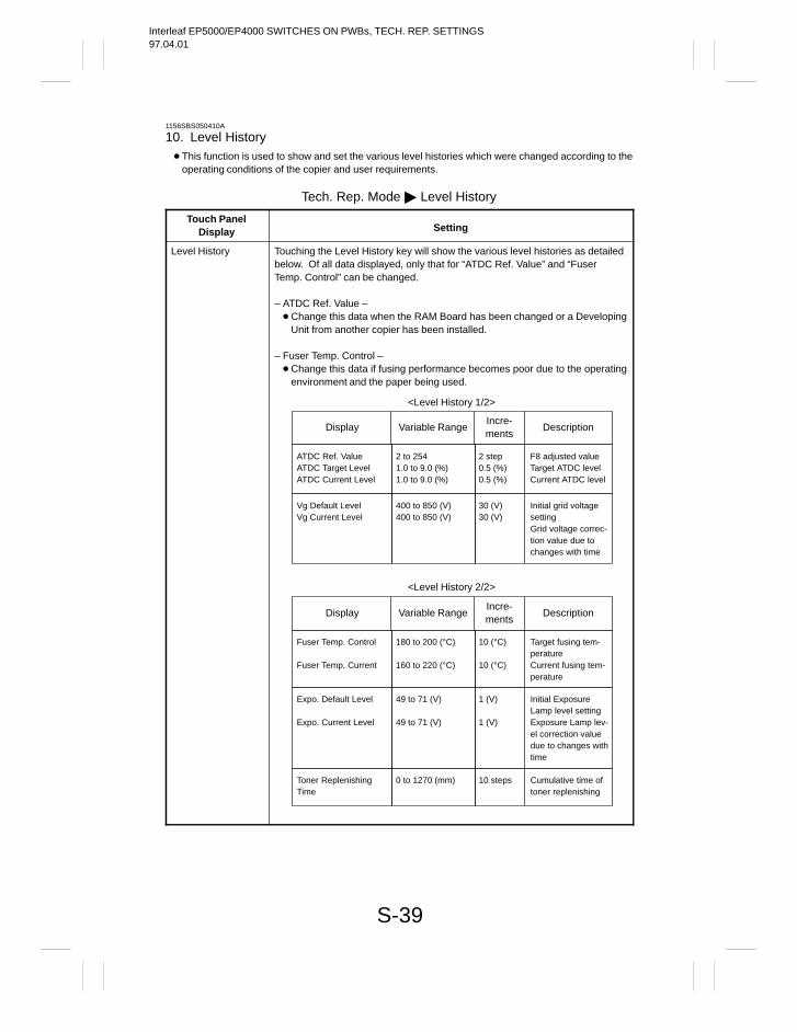
Interleaf EP5000/EP4000 SWITCHES ON PWBs, TECH. REP. SETTINGS97.04.01
S-39
1156SBS050410A
10. Level History This function is used to show and set the various level histories which were changed according to the
operating conditions of the copier and user requirements.
Tech. Rep. Mode Level History
Touch PanelDisplay Setting
Level History Touching the Level History key will show the various level histories as detailedbelow. Of all data displayed, only that for “ATDC Ref. Value” and “FuserTemp. Control” can be changed.
– ATDC Ref. Value – Change this data when the RAM Board has been changed or a Developing
Unit from another copier has been installed.
– Fuser Temp. Control – Change this data if fusing performance becomes poor due to the operating
environment and the paper being used.
<Level History 1/2>
Display Variable RangeIncre-ments
Description
ATDC Ref. ValueATDC Target LevelATDC Current Level
2 step0.5 (%)0.5 (%)
F8 adjusted valueTarget ATDC levelCurrent ATDC level
2 to 2541.0 to 9.0 (%)1.0 to 9.0 (%)
Vg Default LevelVg Current Level
30 (V)30 (V)
Initial grid voltagesettingGrid voltage correc-tion value due tochanges with time
400 to 850 (V)400 to 850 (V)
<Level History 2/2>
Display Variable RangeIncre-ments
Description
Fuser Temp. Control
Fuser Temp. Current
10 (°C)
10 (°C)
Target fusing tem-peratureCurrent fusing tem-perature
180 to 200 (°C)
160 to 220 (°C)
Expo. Default Level
Expo. Current Level
1 (V)
1 (V)
Initial ExposureLamp level settingExposure Lamp lev-el correction valuedue to changes withtime
49 to 71 (V)
49 to 71 (V)
Toner ReplenishingTime
10 steps Cumulative time oftoner replenishing
0 to 1270 (mm)
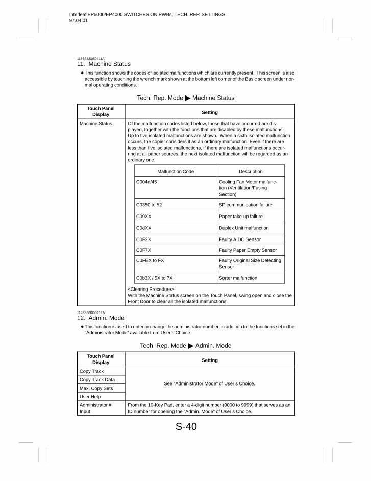
Interleaf EP5000/EP4000 SWITCHES ON PWBs, TECH. REP. SETTINGS97.04.01
S-40
1156SBS050411A
11. Machine Status This function shows the codes of isolated malfunctions which are currently present. This screen is also
accessible by touching the wrench mark shown at the bottom left corner of the Basic screen under nor-mal operating conditions.
Tech. Rep. Mode Machine Status
Touch PanelDisplay Setting
Machine Status Of the malfunction codes listed below, those that have occurred are dis-played, together with the functions that are disabled by these malfunctions.Up to five isolated malfunctions are shown. When a sixth isolated malfunctionoccurs, the copier considers it as an ordinary malfunction. Even if there areless than five isolated malfunctions, if there are isolated malfunctions occur-ring at all paper sources, the next isolated malfunction will be regarded as anordinary one.
Malfunction Code Description
C09XX Paper take-up failure
C0dXX Duplex Unit malfunction
C0350 to 52 SP communication failure
C0F2X Faulty AIDC Sensor
C0FEX to FX Faulty Original Size DetectingSensor
C004d/45 Cooling Fan Motor malfunc-tion (Ventilation/Fusing Section)
C0b3X / 5X to 7X Sorter malfunction
C0F7X Faulty Paper Empty Sensor
<Clearing Procedure>With the Machine Status screen on the Touch Panel, swing open and close theFront Door to clear all the isolated malfunctions.
1149SBS050412A
12. Admin. Mode This function is used to enter or change the administrator number, in addition to the functions set in the
“Administrator Mode” available from User’s Choice.
Tech. Rep. Mode Admin. Mode
Touch PanelDisplay Setting
Copy Track
Copy Track Data
Max. Copy SetsSee “Administrator Mode” of User’s Choice.
User Help
Administrator #Input
From the 10-Key Pad, enter a 4-digit number (0000 to 9999) that serves as anID number for opening the “Admin. Mode” of User’s Choice.
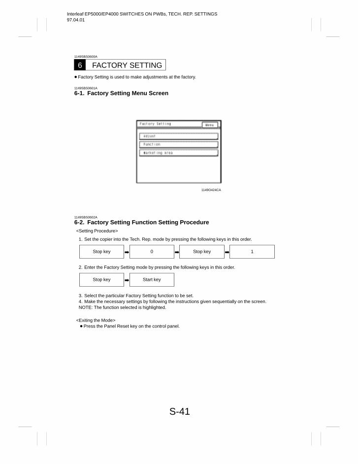
Interleaf EP5000/EP4000 SWITCHES ON PWBs, TECH. REP. SETTINGS97.04.01
S-41
1149SBS0600A
FACTORY SETTING6 Factory Setting is used to make adjustments at the factory.
1149SBS0601A
6-1. Factory Setting Menu Screen
1149O424CA
1149SBS0602A
6-2. Factory Setting Function Setting Procedure<Setting Procedure>
1. Set the copier into the Tech. Rep. mode by pressing the following keys in this order.
Stop key 0 Stop key 1
2. Enter the Factory Setting mode by pressing the following keys in this order.
Stop key Start key
3. Select the particular Factory Setting function to be set.4. Make the necessary settings by following the instructions given sequentially on the screen.NOTE: The function selected is highlighted.
<Exiting the Mode> Press the Panel Reset key on the control panel.
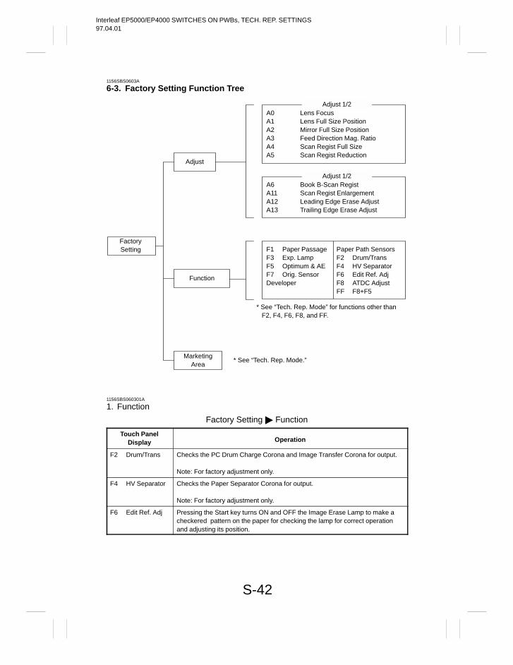
Interleaf EP5000/EP4000 SWITCHES ON PWBs, TECH. REP. SETTINGS97.04.01
S-42
1156SBS0603A
6-3. Factory Setting Function Tree
FactorySetting
Adjust
Function
MarketingArea
A0 Lens FocusA1 Lens Full Size PositionA2 Mirror Full Size PositionA3 Feed Direction Mag. RatioA4 Scan Regist Full SizeA5 Scan Regist Reduction
Adjust 1/2
A6 Book B-Scan RegistA11 Scan Regist EnlargementA12 Leading Edge Erase AdjustA13 Trailing Edge Erase Adjust
Adjust 1/2
* See “Tech. Rep. Mode” for functions other thanF2, F4, F6, F8, and FF.
* See “Tech. Rep. Mode.”
F1 Paper PassageF3 Exp. LampF5 Optimum & AEF7 Orig. SensorDeveloper
Paper Path SensorsF2 Drum/TransF4 HV SeparatorF6 Edit Ref. AdjF8 ATDC AdjustFF F8+F5
1156SBS060301A
1. Function
Factory Setting Function
Touch PanelDisplay Operation
F2 Drum/Trans Checks the PC Drum Charge Corona and Image Transfer Corona for output.
Note: For factory adjustment only.
F4 HV Separator Checks the Paper Separator Corona for output.
Note: For factory adjustment only.
F6 Edit Ref. Adj Pressing the Start key turns ON and OFF the Image Erase Lamp to make acheckered pattern on the paper for checking the lamp for correct operationand adjusting its position.

Interleaf EP5000/EP4000 SWITCHES ON PWBs, TECH. REP. SETTINGS97.04.01
S-43
– Components Energized in “Function” –
Component F1 F2 F3 F4 F5 F6 F7 F8 FF
Main Drive Motor
Fan Motors
Toner Replenishing Motor
Paper take-up
Scan
Exposure Lamp
Main Erase Lamp
Image Erase Lamp
Synchronizing Rollers
PC Drum Paper SeparatorFingers
PC Drum Charge Coronaand Image Transfer Corona
Paper Separator Corona anddeveloping bias
Misfeed detection
Malfunction detection
: Energized : Remains deenergized
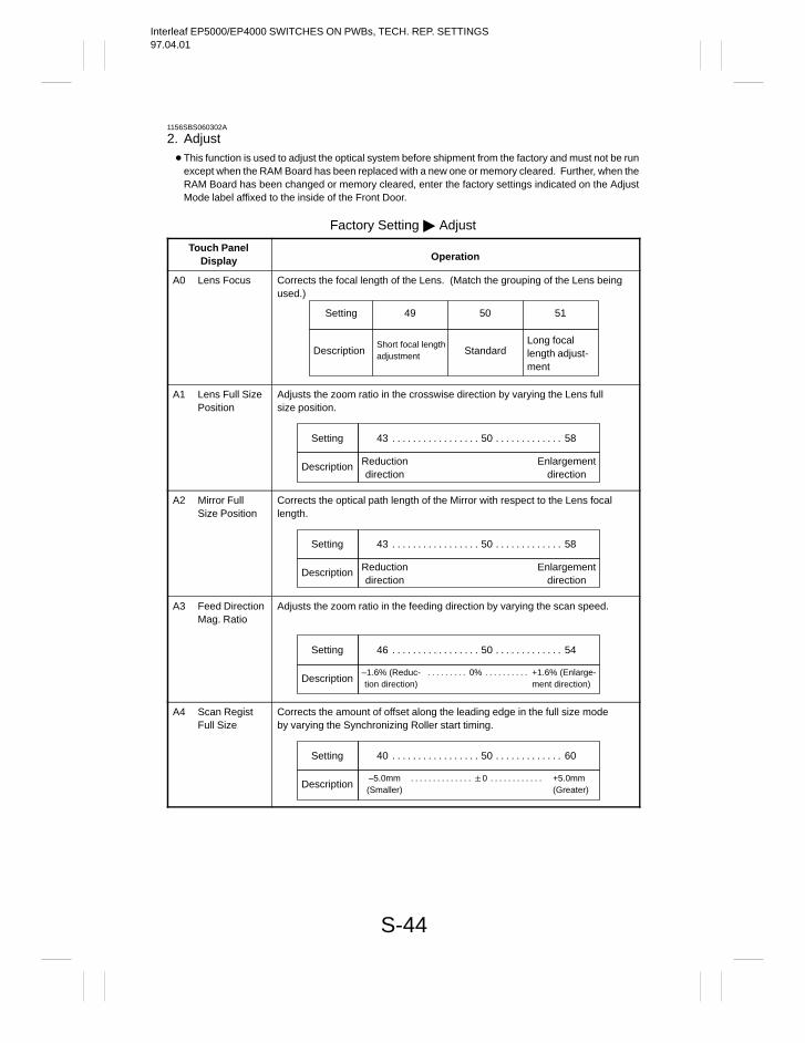
Interleaf EP5000/EP4000 SWITCHES ON PWBs, TECH. REP. SETTINGS97.04.01
S-44
1156SBS060302A
2. Adjust This function is used to adjust the optical system before shipment from the factory and must not be run
except when the RAM Board has been replaced with a new one or memory cleared. Further, when theRAM Board has been changed or memory cleared, enter the factory settings indicated on the AdjustMode label affixed to the inside of the Front Door.
Factory Setting Adjust
Touch PanelDisplay Operation
A0 Lens Focus Corrects the focal length of the Lens. (Match the grouping of the Lens beingused.)
Setting 49 50 51
DescriptionShort focal lengthadjustment Standard
Long focallength adjust-ment
A1 Lens Full SizePosition
Adjusts the zoom ratio in the crosswise direction by varying the Lens fullsize position.
Setting 43 50 58. . . . . . . . . . . . . . . . . . . . . . . . . . . . . .
Description Reductiondirection
Enlargementdirection
A2 Mirror FullSize Position
Corrects the optical path length of the Mirror with respect to the Lens focallength.
Setting 43 50 58. . . . . . . . . . . . . . . . . . . . . . . . . . . . . .
Description Reductiondirection
Enlargementdirection
A3 Feed DirectionMag. Ratio
Adjusts the zoom ratio in the feeding direction by varying the scan speed.
Setting 46 50 54. . . . . . . . . . . . . . . . . . . . . . . . . . . . . .
Description–1.6% (Reduc-tion direction)
+1.6% (Enlarge-ment direction)
0%. . . . . . . . . . . . . . . . . . .
A4 Scan RegistFull Size
Corrects the amount of offset along the leading edge in the full size modeby varying the Synchronizing Roller start timing.
Setting 40 50 60. . . . . . . . . . . . . . . . . . . . . . . . . . . . . .
Description–5.0mm(Smaller)
+5.0mm(Greater)
0. . . . . . . . . . . . . . . . . . . . . . . . . .
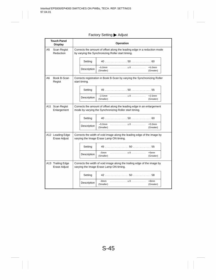
Interleaf EP5000/EP4000 SWITCHES ON PWBs, TECH. REP. SETTINGS97.04.01
S-45
Factory Setting Adjust
Touch PanelDisplay Operation
A5 Scan RegistReduction
Corrects the amount of offset along the leading edge in a reduction modeby varying the Synchronizing Roller start timing.
Setting 40 50 60. . . . . . . . . . . . . . . . . . . . . . . . . . . . . .
Description–5.0mm(Smaller)
+5.0mm(Greater)
0. . . . . . . . . . . . . . . . . . . . . . . . . .
A6 Book B-ScanRegist
Corrects registration in Book B-Scan by varying the Synchronizing Rollerstart timing.
Setting 45 50 55. . . . . . . . . . . . . . . . . . . . . . . . . . . . . .
Description–2.5mm(Smaller)
+2.5mm(Greater)
0. . . . . . . . . . . . . . . . . . . . . . . . . .
A11 Scan RegistEnlargement
Corrects the amount of offset along the leading edge in an enlargementmode by varying the Synchronizing Roller start timing.
Setting 40 50 60. . . . . . . . . . . . . . . . . . . . . . . . . . . . . .
Description–5.0mm(Smaller)
+5.0mm(Greater)
0. . . . . . . . . . . . . . . . . . . . . . . . . .
A12 Leading EdgeErase Adjust
Corrects the width of void image along the leading edge of the image byvarying the Image Erase Lamp ON timing.
Setting 45 50 55. . . . . . . . . . . . . . . . . . . . . . . . . . . . . .
Description–5mm
(Smaller)+5mm(Greater)
0. . . . . . . . . . . . . . . . . . . . . . . . . .
A13 Trailing EdgeErase Adjust
Corrects the width of void image along the trailing edge of the image byvarying the Image Erase Lamp ON timing.
Setting 42 50 58. . . . . . . . . . . . . . . . . . . . . . . . . . . . . .
Description–8mm
(Smaller)+8mm(Greater)
0. . . . . . . . . . . . . . . . . . . . . . . . . .

Interleaf EP5000/EP4000 SWITCHES ON PWBs, TECH. REP. SETTINGS97.04.01
Copyright1997 MINOLTA Co., Ltd.
Printed in Japan
Use of this manual shouldbe strictly supervised to avoid disclosure of confidential information.
1156-7997-11 97046000
1156SBS000EA
Interleaf EP5000/EP4000 TROUBLESHOOTING97.04.01
1156SBT000AA
Interleaf EP5000/EP4000 TROUBLESHOOTING97.04.01
i
1156SBT000BA
CONTENTS
INTRODUCTION1
1-1. General Precautions T-1. . . . . . . . . . . . . . . . . . . . . . . . . . . . . . . . . . . . . . . . .
1-2. How to Use This Book T-1. . . . . . . . . . . . . . . . . . . . . . . . . . . . . . . . . . . . . . .
1-3. Reading the Text T-1. . . . . . . . . . . . . . . . . . . . . . . . . . . . . . . . . . . . . . . . . . . .
I/O PORT CHECK2
2-1. Controlled Parts Check Procedure T-2. . . . . . . . . . . . . . . . . . . . . . . . . . . . .
2-2. I/O Port Check List T-5. . . . . . . . . . . . . . . . . . . . . . . . . . . . . . . . . . . . . . . . . .
PAPER TRANSPORT FAILURE3
3-1. Paper Misfeed T-20. . . . . . . . . . . . . . . . . . . . . . . . . . . . . . . . . . . . . . . . . . . . .
3-2. Misfeed Detection Types and Detection Timings T-22. . . . . . . . . . . . . . . .
3-3. Misfeed Clearing Procedures T-24. . . . . . . . . . . . . . . . . . . . . . . . . . . . . . . .
1) Copier Paper Take-Up Misfeed T-24. . . . . . . . . . . . . . . . . . . . . . . . . . . . . 2) Transport/Separator Misfeed T-27. . . . . . . . . . . . . . . . . . . . . . . . . . . . . . 3) Multi Bypass Misfeed T-30. . . . . . . . . . . . . . . . . . . . . . . . . . . . . . . . . . . . . 4) Fusing/Exit misfeed T-32. . . . . . . . . . . . . . . . . . . . . . . . . . . . . . . . . . . . . . 5) PF-205 Paper Take-Up Misfeed T-34. . . . . . . . . . . . . . . . . . . . . . . . . . . . 6) PF-105 Paper Take-Up Misfeed T-36. . . . . . . . . . . . . . . . . . . . . . . . . . . . 7) AD-9 Vertical Transport/Storage Misfeed T-38. . . . . . . . . . . . . . . . . . . . 8) AD-9 Paper Take-Up Misfeed T-41. . . . . . . . . . . . . . . . . . . . . . . . . . . . . .
MALFUNCTIONS4
4-1. Detection Timings Classified by Malfunction Codes T-43. . . . . . . . . . . . .
4-2. Troubleshooting Procedures T-57. . . . . . . . . . . . . . . . . . . . . . . . . . . . . . . .
1) C0000: Main Drive Motor M1’s Failure to Turn T-57. . . . . . . . . . . . . . . . C0001: Main Drive Motor M1 Turning at Abnormal Timing
2) C0040: Suction Fan Motor M4’s Failure to Turn T-59. . . . . . . . . . . . . . 3) C0046: Fusing Section Cooling Fan Motor M15’s
Failure to Turn T-61. . . . . . . . . . . . . . . . . . . . . . . . . . . . . . . . . . . . C0047: Fusing Section Cooling Fan Motor M15 Turning at
Abnormal Timing
Interleaf EP5000/EP4000 TROUBLESHOOTING97.04.01
ii
4) C004A: Original Glass Cooling Fan Motor M5’s Failure to Turn T-63. . . . . . . . . . . . . . . . . . . . . . . . . . . . . . . . . . .
C004b: Original Glass Cooling Fan Motor M5 Turning at Abnormal Timing
C004C: Ventilation Fan Motor M3’s Failure to TurnC004d: Ventilation Fan Motor M3 Turning at Abnormal Timing
5) C0070: Main Hopper Toner Replenishing Motor M8’s Failure to Turn T-65. . . . . . . . . . . . . . . . . . . . . . . . . . . . . . . . . . .
C0071: Main Hopper Toner Replenishing Motor M8 Turning at Abnormal Timing
C0072: Sub Hopper Toner Replenishing Motor M9’s Failure to Turn
6) C0200 Corona Malfunctions T-67. . . . . . . . . . . . . . . . . . . . . . . . . . . . . . . 7) C03##: Master Board/Harness Malfunctions T-68. . . . . . . . . . . . . . . . . 8) C0400: Exposure Lamp LA1’s Failure to Turn ON T-69. . . . . . . . . . . .
C0410: Exposure Lamp LA1 Turning ON at Abnormal Timing9) C0500: Warming-up Failure T-71. . . . . . . . . . . . . . . . . . . . . . . . . . . . . . .
C0510: Abnormally Low Fusing TemperatureC0520: Abnormally High Fusing Temperature
10)C0600: Scanner Motor M2 Malfunction T-73. . . . . . . . . . . . . . . . . . . . . . C06FX: Signal Failure
11) C0610: Lens Motor M6 Malfunction T-75. . . . . . . . . . . . . . . . . . . . . . . . . C0620: Mirror Motor M7 malfunction
12)C0910: 2nd Drawer Upward Motion Failure T-77. . . . . . . . . . . . . . . . . . C0914: 2nd Drawer Paper Lift-Up Motor M14’s Failure to TurnC0920: 1st Drawer Upward Motion FailureC0924: 1st Drawer Paper Lift-Up Motor M13’s Failure to Turn
13)C0900: 3rd Drawer Upward Motion Failure T-79. . . . . . . . . . . . . . . . . . C0904: 3rd Drawer Paper Lift-Up Motor M24’s Failure to TurnC0950: 4th Drawer Upward Motion FailureC0954: 4th Drawer Paper Lift-Up Motor M25’s Failure to Turn
14)C0911: 2nd Drawer Upward Motion Failure (Inch Areas) T-81. . . . . . . C0912: 2nd Drawer Downward Motion FailureC0913: 2nd Drawer Upward Motion FailureC0916: 2nd Drawer Ejection Failure
15)C0921: 1st Drawer Upward Motion Failure (Inch Areas) T-83. . . . . . . C0922: 1st Drawer Downward Motion FailureC0923: 1st Drawer Upward Motion FailureC0926: 1st Drawer Ejection Failure
16)C0901: 3rd Drawer Upward Motion Failure (Inch Areas) T-85. . . . . . . C0902: 3rd Drawer Downward Motion FailureC0903: 3rd Drawer Upward Motion FailureC0906: 3rd Drawer Ejection Failure
17)C0951: 4th Drawer Upward Motion Failure (Inch Areas) T-87. . . . . . .
Interleaf EP5000/EP4000 TROUBLESHOOTING97.04.01
iii
C0952: 4th Drawer Downward Motion FailureC0953: 4th Drawer Upward Motion FailureC0956: 4th Drawer Ejection Failure
18)C0990: Main Tray Upward Motion Failure T-89. . . . . . . . . . . . . . . . . . . C0991: Main Tray Downward Motion FailureC0992: Main Tray Downward Motion FailureC0993: Main Tray Upward Motion FailureC0994: Elevator Motor M26’s Failure to Turn
19)C0998: Shifter Transfer Failure T-91. . . . . . . . . . . . . . . . . . . . . . . . . . . . C0999: Shifter Return FailureC099A: Shifter Return FailureC099b: Shifter Transfer FailureC099C: Shift Motor M27’s Failure to Turn
20)C099E: Shift Gate Position Detecting Failure T-93. . . . . . . . . . . . . . . . . C099F: Shift Gate Position Detecting FailureC0996: 3rd Drawer Lock Release FailureC0F79: Paper Empty Sensor Failure
21)C0d00: Duplex Unit Front/Rear Edge Guide PlateHome Position Detection Failure T-95. . . . . . . . . . . . . . . . . . . .
C0d20: Duplex Unit Gate Unit Home Position Detection FailureC0d50: Duplex Unit Drive Motor M31’s Failure to TurnC0d51: Duplex Unit Drive Motor M31 Turning at Abnormal Timing
22)C0E00: Main Erase Lamp LA2’s Failure to Turn ON T-97. . . . . . . . . . . C0E01: Main Erase Lamp LA2 Turning ON at Abnormal Timing
23)C0E20: Image Erase Lamp LA3’s Failure to Turn ON T-98. . . . . . . . . 24)C0F02: Original Size Detecting Board UN2 Malfunction T-99. . . . . . . 25)C0F10: AE Sensor Board PWB-H Malfunction T-101. . . . . . . . . . . . . . 26)C0F20: AIDC Sensor Board PWB-G Variation
Correction Failure T-102. . . . . . . . . . . . . . . . . . . . . . . . . . . . . . . C0F22: AIDC Sensor Board PWB-G Grid Voltage (Vg) Correction
FailureC0F23: AIDC Sensor Board PWB-G Exposure Correction Failure
27)C0F30: ATDC Sensor UN3 Failure T-103. . . . . . . . . . . . . . . . . . . . . . . . C0F31: ATDC Sensor UN3 Failure
4-3. Power Malfunctions T-104. . . . . . . . . . . . . . . . . . . . . . . . . . . . . . . . . . . . . . .
1) Main Relay Does Not Turn ON. T-104. . . . . . . . . . . . . . . . . . . . . . . . . . . 2) Main Relay Turns ON But the Control Panel
Gives No Display T-106. . . . . . . . . . . . . . . . . . . . . . . . . . . . . . . . . . . . . . .
4-4. Miscellaneous T-107. . . . . . . . . . . . . . . . . . . . . . . . . . . . . . . . . . . . . . . . . . . .
IMAGE FAILURE5
5-1. Image Failure Troubleshooting T-108. . . . . . . . . . . . . . . . . . . . . . . . . . . . .

Interleaf EP5000/EP4000 TROUBLESHOOTING97.04.01
iv
5-2. Initial Checks T-108. . . . . . . . . . . . . . . . . . . . . . . . . . . . . . . . . . . . . . . . . . . . 5-3. Troubleshooting Procedures Classified by Image Failure T-110. . . . . . .
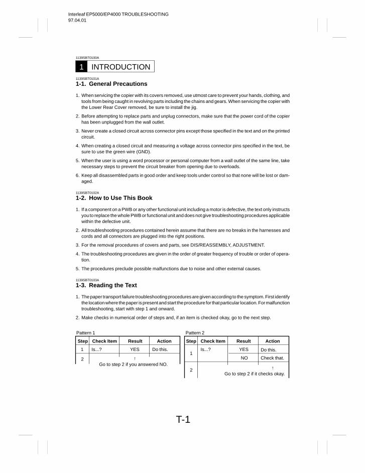
Interleaf EP5000/EP4000 TROUBLESHOOTING97.04.01
T-1
1139SBT0100A
INTRODUCTION11139SBT0101A
1-1. General Precautions
1. When servicing the copier with its covers removed, use utmost care to prevent your hands, clothing, andtools from being caught in revolving parts including the chains and gears. When servicing the copier withthe Lower Rear Cover removed, be sure to install the jig.
2. Before attempting to replace parts and unplug connectors, make sure that the power cord of the copierhas been unplugged from the wall outlet.
3. Never create a closed circuit across connector pins except those specified in the text and on the printedcircuit.
4. When creating a closed circuit and measuring a voltage across connector pins specified in the text, besure to use the green wire (GND).
5. When the user is using a word processor or personal computer from a wall outlet of the same line, takenecessary steps to prevent the circuit breaker from opening due to overloads.
6. Keep all disassembled parts in good order and keep tools under control so that none will be lost or dam-aged.
1139SBT0102A
1-2. How to Use This Book
1. If a component on a PWB or any other functional unit including a motor is defective, the text only instructsyou to replace the whole PWB or functional unit and does not give troubleshooting procedures applicablewithin the defective unit.
2. All troubleshooting procedures contained herein assume that there are no breaks in the harnesses andcords and all connectors are plugged into the right positions.
3. For the removal procedures of covers and parts, see DIS/REASSEMBLY, ADJUSTMENT.
4. The troubleshooting procedures are given in the order of greater frequency of trouble or order of opera-tion.
5. The procedures preclude possible malfunctions due to noise and other external causes.
1139SBT0103A
1-3. Reading the Text
1. The paper transport failure troubleshooting procedures are given according to the symptom. First identifythe location where the paper is present and start the procedure for that particular location. For malfunctiontroubleshooting, start with step 1 and onward.
2. Make checks in numerical order of steps and, if an item is checked okay, go to the next step.
↑
↑
Check ItemStep Result Action
1
2
Is...? YES Do this.
Go to step 2 if you answered NO.
Pattern 1 Pattern 2
Check ItemStep Result Action
1
2
Is...? YES Do this.
NO Check that.
Go to step 2 if it checks okay.
Interleaf EP5000/EP4000 TROUBLESHOOTING97.04.01
T-2
1151SBT0200A
I/O PORT CHECK21156SBT0201A
2-1. Controlled Parts Check Procedure
To allow the Tech. Rep. to easily and safely determine whether a particular controlled part is fully opera-tional, this copier provides the following provision: checking the data of the I/O port of the board IC withthe copier in the standby state (including a misfeed, malfunction, and closure failure condition) allows theTech. Rep. to determine whether a signal is properly input to, and output from, a controlled part.
<Procedure>
1) On the circuit diagram accompanying the text, locate the I/O port of the controlled part which is probablydefective when a misfeed or malfunction occurs.
2) Select the “IC Port Data Check” function of “I/O Check” in the Tech. Rep. mode and access the screenwhich contains the port identified in step 1 above. (See SWITCHES ON PWBs/TECH. REP. MODE.)
3) Change or check the input or output port data to determine whether the controlled part is operationaland signals are properly input and output.
4) If the controlled part does not operate properly after changing the output port data, select “ControllerBoard Check” of “I/O Check” in the Tech. Rep. mode and determine whether the board is responsiblefor that malfunction or not.
Note: Only the output ports given on pages T-37 and 38 may be checked by “Controller Board Check”of “I/O Check” in the Tech. Rep. mode.
Interleaf EP5000/EP4000 TROUBLESHOOTING97.04.01
T-3
<Controlled Part Check Procedure by Changing Input Port Data>
Example: When a paper misfeed occurs in the paper take-up section of the copier, 1st Drawer Pa-per Take-Up Sensor PC56 is considered to be responsible for it.
<Procedure>
1) Remove the sheet of paper misfed and reset the misfeed.
2) From the I/O port check list, it is found that the H/L input signal to PC56 is supplied from PWB-A(IC3A) APB3.
3) Select “IC Port Check” from the I/O Check function in the Tech. Rep. mode and access thescreen which includes the input ports of PWB-A (IC3A) APB3.
4) Check that the input port data of PWB-A (IC3A) APB3 on the screen is “H” (sensor being un-blocked).
5) Move the PC56 actuator to block the sensor.
6) Return to the “I/O Check” basic screen once, select “IC Port Check” again, choose the screenwhich includes the APB3 input port data, and make sure that the data has changed from “H”to “L”.
L: PC56 is operational. H: PC56 is faulty.
Interleaf EP5000/EP4000 TROUBLESHOOTING97.04.01
T-4
<Controlled Part Check Procedure by Changing Output Port Data>
Example: When a manual paper misfeed occurs, Manual Feed Paper Take-Up Clutch CL3 is con-sidered to be responsible for it.
<Procedure>
1) Remove the sheet of paper misfed and reset the misfeed.
2) From the I/O port check list, it is found that the ON/OFF output signal of CL3 is supplied fromPWB-A (IC5A) BPA1.
3) Select “IC Port Check” from the I/O Check function in the Tech. Rep. mode and access thescreen which includes the output ports of PWB-A (IC5A) BPA1.
4) Check that the output port data of PWB-A (IC5A) BPA1 on the screen is “1” (CL3 is deener-gized).
5) Touch the “CHANGE” key on the screen to change the data from “1” to “0”, causing CL3 to beenergized for approx. 5 seconds. This allows you to determine whether the Clutch is “operation-al or faulty” by checking for the Clutch sound.
Operational: Sound produced. Faulty: No sound produced.
6) If CL3 was not energized, make the “Controller Board Check” in the same mode (for some elec-trical parts only).
7) If the “ON” signal of CL51 is not output from PWB-A, the corresponding malfunction code isdisplayed.
* For CL3, “C0337” is displayed.
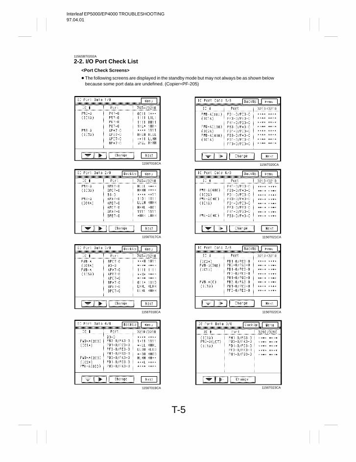
Interleaf EP5000/EP4000 TROUBLESHOOTING97.04.01
T-5
1156SBT0202A
2-2. I/O Port Check List<Port Check Screens>
The following screens are displayed in the standby mode but may not always be as shown belowbecause some port data are undefined. (Copier+PF-205)
1156T021CA1156T017CA
1156T018CA
1156T019CA
1156T020CA
1156T023CA
1156T022CA
1156T016CA
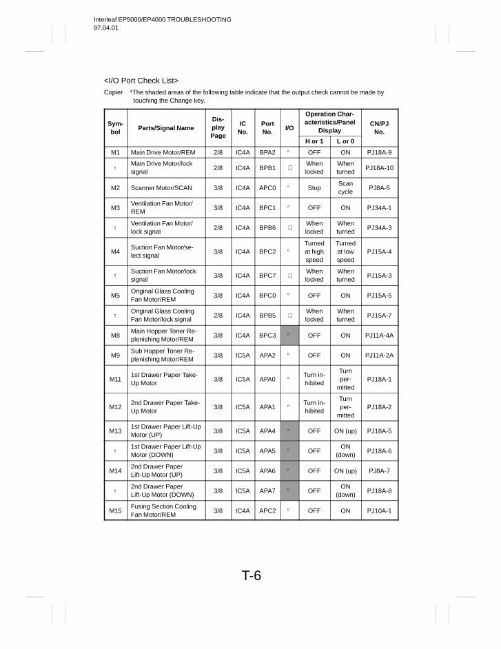
Interleaf EP5000/EP4000 TROUBLESHOOTING97.04.01
T-6
<I/O Port Check List>Copier *The shaded areas of the following table indicate that the output check cannot be made by
touching the Change key.
Sym-bol
Parts/Signal NameDis-play IC
No.PortNo.
I/O
Operation Char-acteristics/Panel
DisplayCN/PJ
No.Page
H or 1 L or 0
M1 Main Drive Motor/REM 2/8 IC4A BPA2 OFF ON PJ18A-9
↑Main Drive Motor/locksignal
2/8 IC4A BPB1 Whenlocked
Whenturned
PJ18A-10
M2 Scanner Motor/SCAN 3/8 IC4A APC0 StopScancycle
PJ8A-5
M3Ventilation Fan Motor/REM
3/8 IC4A BPC1 OFF ON PJ34A-1
↑Ventilation Fan Motor/lock signal
2/8 IC4A BPB6 Whenlocked
Whenturned
PJ34A-3
M4Suction Fan Motor/se-lect signal
3/8 IC4A BPC2
Turnedat highspeed
Turnedat lowspeed
PJ15A-4
↑Suction Fan Motor/locksignal
3/8 IC4A BPC7 Whenlocked
Whenturned
PJ15A-3
M5Original Glass CoolingFan Motor/REM
3/8 IC4A BPC0 OFF ON PJ15A-5
↑Original Glass CoolingFan Motor/lock signal
2/8 IC4A BPB5 Whenlocked
Whenturned
PJ15A-7
M8Main Hopper Toner Re-plenishing Motor/REM
3/8 IC4A BPC3 OFF ON PJ11A-4A
M9Sub Hopper Toner Re-plenishing Motor/REM
3/8 IC5A APA2 OFF ON PJ11A-2A
M111st Drawer Paper Take-Up Motor
3/8 IC5A APA0 Turn in-hibited
Turnper-
mittedPJ18A-1
M122nd Drawer Paper Take-Up Motor
3/8 IC5A APA1 Turn in-hibited
Turnper-
mittedPJ18A-2
M131st Drawer Paper Lift-UpMotor (UP)
3/8 IC5A APA4 OFF ON (up) PJ18A-5
↑1st Drawer Paper Lift-UpMotor (DOWN)
3/8 IC5A APA5 OFFON
(down)PJ18A-6
M142nd Drawer PaperLift-Up Motor (UP)
3/8 IC5A APA6 OFF ON (up) PJ8A-7
↑2nd Drawer Paper Lift-Up Motor (DOWN)
3/8 IC5A APA7 OFFON
(down)PJ18A-8
M15Fusing Section CoolingFan Motor/REM
3/8 IC4A APC2 OFF ON PJ10A-1
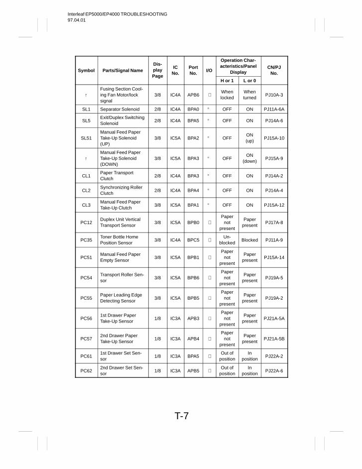
Interleaf EP5000/EP4000 TROUBLESHOOTING97.04.01
T-7
Symbol Parts/Signal NameDis-play IC
No.PortNo.
I/O
Operation Char-acteristics/Panel
DisplayCN/PJ
No.Page
H or 1 L or 0
↑Fusing Section Cool-ing Fan Motor/locksignal
3/8 IC4A APB6 Whenlocked
Whenturned
PJ10A-3
SL1 Separator Solenoid 2/8 IC4A BPA0 OFF ON PJ11A-6A
SL5Exit/Duplex SwitchingSolenoid
2/8 IC4A BPA5 OFF ON PJ14A-6
SL51Manual Feed PaperTake-Up Solenoid(UP)
3/8 IC5A BPA2 OFFON(up)
PJ15A-10
↑Manual Feed PaperTake-Up Solenoid(DOWN)
3/8 IC5A BPA3 OFFON
(down)PJ15A-9
CL1Paper TransportClutch
2/8 IC4A BPA3 OFF ON PJ14A-2
CL2Synchronizing RollerClutch
2/8 IC4A BPA4 OFF ON PJ14A-4
CL3Manual Feed PaperTake-Up Clutch
3/8 IC5A BPA1 OFF ON PJ15A-12
PC12Duplex Unit VerticalTransport Sensor
3/8 IC5A BPB0 Paper
notpresent
Paperpresent
PJ17A-8
PC35Toner Bottle HomePosition Sensor
3/8 IC4A BPC5 Un-
blockedBlocked PJ11A-9
PC51Manual Feed PaperEmpty Sensor
3/8 IC5A BPB1 Paper
notpresent
Paperpresent
PJ15A-14
PC54Transport Roller Sen-sor
3/8 IC5A BPB6 Paper
notpresent
Paperpresent
PJ19A-5
PC55Paper Leading EdgeDetecting Sensor
3/8 IC5A BPB5 Paper
notpresent
Paperpresent
PJ19A-2
PC561st Drawer PaperTake-Up Sensor
1/8 IC3A APB3 Paper
notpresent
Paperpresent
PJ21A-5A
PC572nd Drawer PaperTake-Up Sensor
1/8 IC3A APB4 Paper
notpresent
Paperpresent
PJ21A-5B
PC611st Drawer Set Sen-sor
1/8 IC3A BPA5 Out of
positionIn
positionPJ22A-2
PC622nd Drawer Set Sen-sor
1/8 IC3A APB5 Out of
positionIn
positionPJ22A-6
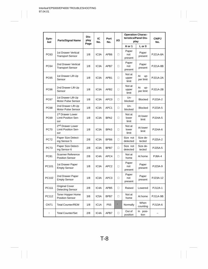
Interleaf EP5000/EP4000 TROUBLESHOOTING97.04.01
T-8
Sym-bol
Parts/Signal NameDis-play IC
No.PortNo.
I/O
Operation Charac-teristics/Panel Dis-
playCN/PJ
No.Page
H or 1 L or 0
PC631st Drawer VerticalTransport Sensor
1/8 IC3A APB6 Papernot
present
Paperpresent
PJ21A-8A
PC642nd Drawer VerticalTransport Sensor
1/8 IC3A APB7 Papernot
present
Paperpresent
PJ21A-8B
PC651st Drawer Lift-UpSensor
1/8 IC3A APB1 Not atupperlimit
At up-per limit
PJ21A-2A
PC662nd Drawer Lift-UpSensor
1/8 IC3A APB2 Not atupperlimit
At up-per limit
PJ21A-2B
PC671st Drawer Lift-UpMotor Pulse Sensor
1/8 IC3A APC0 Un-
blocked Blocked PJ23A-2
PC682nd Drawer Lift-UpMotor Pulse Sensor
1/8 IC3A APC1 Un-
blocked Blocked PJ23A-5
PC691st Drawer LowerLimit Position Sen-sor
1/8 IC3A BPA2 Not atlowerlimit
At lowerlimit
PJ24A-5
PC702nd Drawer LowerLimit Position Sen-sor
1/8 IC3A BPA3 Not atlowerlimit
At lowerlimit
PJ24A-6
PC72Paper Size Detect-ing Sensor 5
2/8 IC3A BPB6 Size notdetected
Size de-tected
PJ25A-2
PC73Paper Size Detect-ing Sensor 6
2/8 IC3A BPB7 Size notdetected
Size de-tected
PJ25A-5
PC81Scanner ReferencePosition Sensor
2/8 IC4A APC4 Not athome
At home PJ8A-4
PC1011st Drawer PaperEmpty Sensor
1/8 IC3A APC2 Papernot
present
Paperpresent
PJ23A-9
PC1022nd Drawer PaperEmpty Sensor
1/8 IC3A APC3 Papernot
present
Paperpresent
PJ23A-12
PC111Original Cover Detecting Sensor
2/8 IC4A APB5 Raised Lowered PJ12A-1
PC112Toner Hopper HomePosition Sensor
3/8 IC5A BPB7 Not athome
At home PJ11A-9B
CNT1 Total Counter/REM 1/8 IC1A P55 NormallyWhen
countingPJ13A-6
↑ Total Counter/Set 2/8 IC4A APB7 Out of
positionIn posi-
tion–
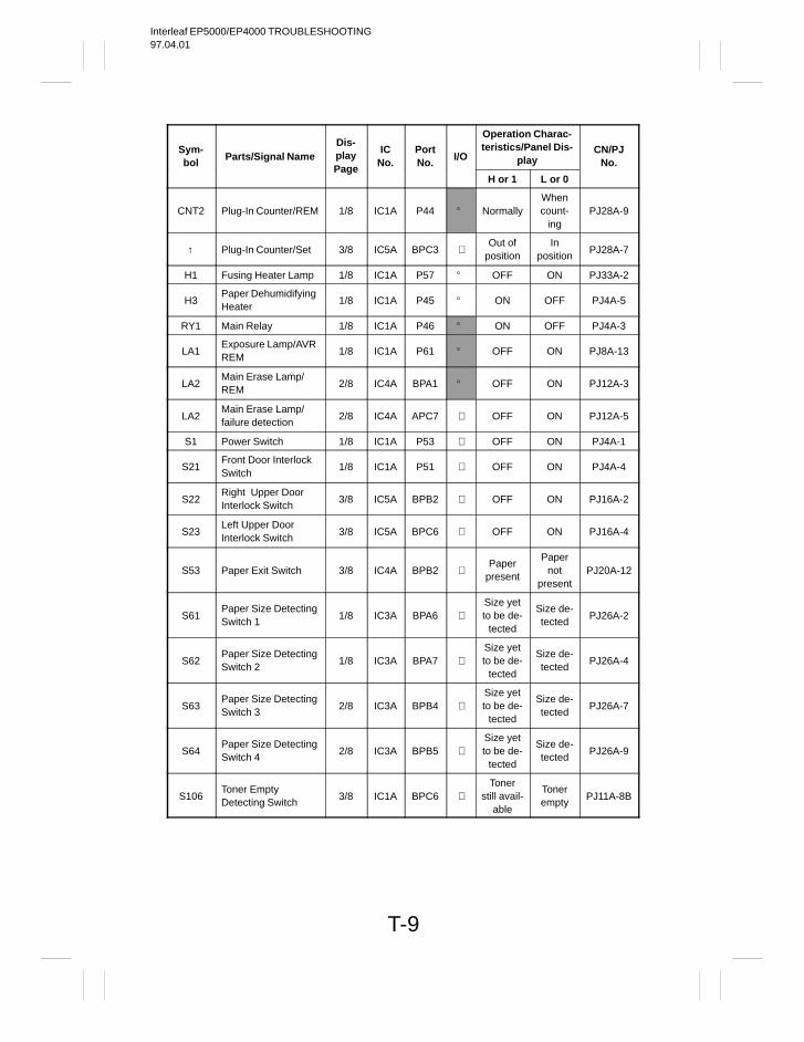
Interleaf EP5000/EP4000 TROUBLESHOOTING97.04.01
T-9
Sym-bol
Parts/Signal NameDis-play IC
No.PortNo.
I/O
Operation Charac-teristics/Panel Dis-
playCN/PJ
No.Page
H or 1 L or 0
CNT2 Plug-In Counter/REM 1/8 IC1A P44 NormallyWhencount-
ingPJ28A-9
↑ Plug-In Counter/Set 3/8 IC5A BPC3 Out of
positionIn
positionPJ28A-7
H1 Fusing Heater Lamp 1/8 IC1A P57 OFF ON PJ33A-2
H3Paper DehumidifyingHeater
1/8 IC1A P45 ON OFF PJ4A-5
RY1 Main Relay 1/8 IC1A P46 ON OFF PJ4A-3
LA1Exposure Lamp/AVRREM
1/8 IC1A P61 OFF ON PJ8A-13
LA2Main Erase Lamp/REM
2/8 IC4A BPA1 OFF ON PJ12A-3
LA2Main Erase Lamp/failure detection
2/8 IC4A APC7 OFF ON PJ12A-5
S1 Power Switch 1/8 IC1A P53 OFF ON PJ4A-1
S21Front Door InterlockSwitch
1/8 IC1A P51 OFF ON PJ4A-4
S22Right Upper Door Interlock Switch
3/8 IC5A BPB2 OFF ON PJ16A-2
S23Left Upper Door Interlock Switch
3/8 IC5A BPC6 OFF ON PJ16A-4
S53 Paper Exit Switch 3/8 IC4A BPB2 Paper
present
Papernot
presentPJ20A-12
S61Paper Size DetectingSwitch 1
1/8 IC3A BPA6 Size yetto be de-
tected
Size de-tected
PJ26A-2
S62Paper Size DetectingSwitch 2
1/8 IC3A BPA7 Size yetto be de-
tected
Size de-tected
PJ26A-4
S63Paper Size DetectingSwitch 3
2/8 IC3A BPB4 Size yetto be de-
tected
Size de-tected
PJ26A-7
S64Paper Size DetectingSwitch 4
2/8 IC3A BPB5 Size yetto be de-
tected
Size de-tected
PJ26A-9
S106Toner Empty Detecting Switch
3/8 IC1A BPC6 Toner
still avail-able
Tonerempty
PJ11A-8B
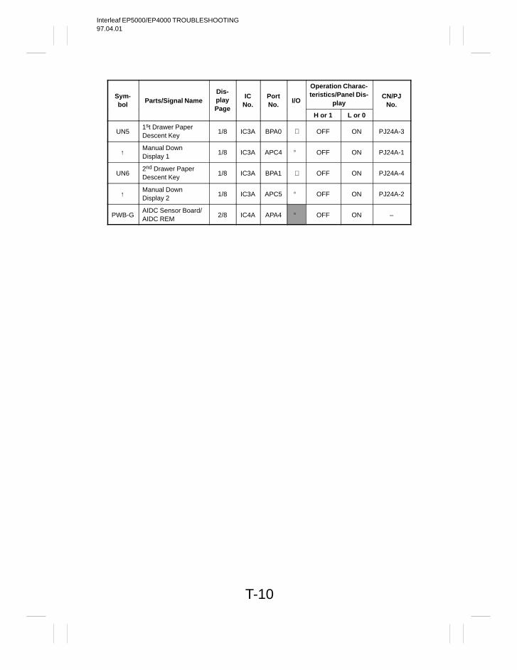
Interleaf EP5000/EP4000 TROUBLESHOOTING97.04.01
T-10
Sym-bol
Parts/Signal NameDis-play IC
No.PortNo.
I/O
Operation Charac-teristics/Panel Dis-
playCN/PJ
No.Page
H or 1 L or 0
UN51st Drawer PaperDescent Key
1/8 IC3A BPA0 OFF ON PJ24A-3
↑Manual Down Display 1
1/8 IC3A APC4 OFF ON PJ24A-1
UN62nd Drawer PaperDescent Key
1/8 IC3A BPA1 OFF ON PJ24A-4
↑Manual Down Display 2
1/8 IC3A APC5 OFF ON PJ24A-2
PWB-GAIDC Sensor Board/AIDC REM
2/8 IC4A APA4 OFF ON –
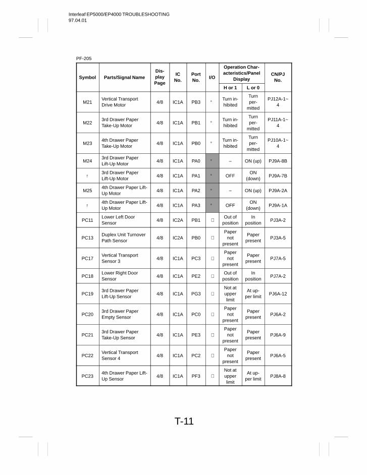
Interleaf EP5000/EP4000 TROUBLESHOOTING97.04.01
T-11
PF-205
Symbol Parts/Signal NameDis-play IC
No.PortNo.
I/O
Operation Char-acteristics/Panel
DisplayCN/PJ
No.Page
H or 1 L or 0
M21Vertical TransportDrive Motor
4/8 IC1A PB3 Turn in-hibited
Turnper-
mitted
PJ12A-1~4
M223rd Drawer PaperTake-Up Motor
4/8 IC1A PB1 Turn in-hibited
Turnper-
mitted
PJ11A-1~4
M234th Drawer PaperTake-Up Motor
4/8 IC1A PB0 Turn in-hibited
Turnper-
mitted
PJ10A-1~4
M243rd Drawer PaperLift-Up Motor
4/8 IC1A PA0 – ON (up) PJ9A-8B
↑3rd Drawer PaperLift-Up Motor
4/8 IC1A PA1 OFFON
(down)PJ9A-7B
M254th Drawer Paper Lift-Up Motor
4/8 IC1A PA2 – ON (up) PJ9A-2A
↑4th Drawer Paper Lift-Up Motor
4/8 IC1A PA3 OFFON
(down)PJ9A-1A
PC11Lower Left Door Sensor
4/8 IC2A PB1 Out of
positionIn
positionPJ3A-2
PC13Duplex Unit TurnoverPath Sensor
4/8 IC2A PB0 Paper
notpresent
Paperpresent
PJ3A-5
PC17Vertical TransportSensor 3
4/8 IC1A PC3 Paper
notpresent
Paperpresent
PJ7A-5
PC18Lower Right DoorSensor
4/8 IC1A PE2 Out of
positionIn
positionPJ7A-2
PC193rd Drawer PaperLift-Up Sensor
4/8 IC1A PG3 Not atupperlimit
At up-per limit
PJ6A-12
PC203rd Drawer PaperEmpty Sensor
4/8 IC1A PC0 Paper
notpresent
Paperpresent
PJ6A-2
PC213rd Drawer PaperTake-Up Sensor
4/8 IC1A PE3 Paper
notpresent
Paperpresent
PJ6A-9
PC22Vertical TransportSensor 4
4/8 IC1A PC2 Paper
notpresent
Paperpresent
PJ6A-5
PC234th Drawer Paper Lift-Up Sensor
4/8 IC1A PF3 Not atupperlimit
At up-per limit
PJ8A-8
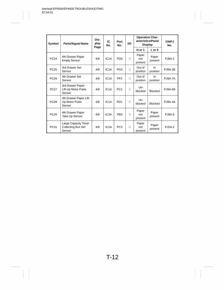
Interleaf EP5000/EP4000 TROUBLESHOOTING97.04.01
T-12
Symbol Parts/Signal NameDis-play IC
No.PortNo.
I/O
Operation Char-acteristics/Panel
DisplayCN/PJ
No.Page
H or 1 L or 0
PC244th Drawer PaperEmpty Sensor
4/8 IC1A PD0 Paper
notpresent
Paperpresent
PJ8A-2
PC253rd Drawer Set Sensor
4/8 IC1A PG2 Out of
positionIn
positionPJ9A-2B
PC264th Drawer Set Sensor
4/8 IC1A PF2 Out of
positionIn
positionPJ9A-7A
PC273rd Drawer PaperLift-Up Motor PulseSensor
4/8 IC1A PC1 Un-
blocked
BlockedPJ9A-5B
PC284th Drawer Paper Lift-Up Motor Pulse Sensor
4/8 IC1A PD1 Un-
blocked
BlockedPJ9A-4A
PC294th Drawer PaperTake-Up Sensor
4/8 IC2A PB3 Paper
notpresent
Paperpresent
PJ8A-5
PC31Large Capacity TonerCollecting Box SetSensor
4/8 IC2A PC3 Paper
notpresent
Paperpresent
PJ2A-2
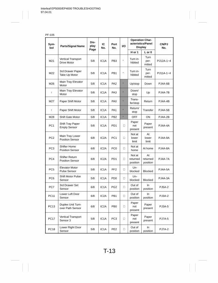
Interleaf EP5000/EP4000 TROUBLESHOOTING97.04.01
T-13
PF-105
Sym-bol
Parts/Signal NameDis-play IC
No.PortNo.
I/O
Operation Char-acteristics/Panel
DisplayCN/PJ
No.Page
H or 1 L or 0
M21Vertical TransportDrive Motor
5/8 IC1A PB3 Turn in-hibited
Turnper-
mittedPJ12A-1~4
M223rd Drawer PaperTake-Up Motor
5/8 IC1A PB1 Turn in-hibited
Turnper-
mittedPJ11A-1~4
M26Main Tray ElevatorMotor
5/8 IC1A PA2 Up/stop Down PJ4A-6B
↑Main Tray ElevatorMotor
5/8 IC1A PA3 Down/stop
Up PJ4A-7B
M27 Paper Shift Motor 5/8 IC1A PA0 Trans-fer/stop
Return PJ4A-4B
↑ Paper Shift Motor 5/8 IC1A PA1 Return/
stopTransfer PJ4A-5B
M28 Shift Gate Motor 5/8 IC1A PB2 OFF ON PJ4A-2B
PC1Shift Tray PaperEmpty Sensor
5/8 IC1A PD1 Paper
notpresent
Paperpresent
PJ4A-4A
PC2Main Tray LowerPosition Sensor
6/8 IC2A PC1 Not atlowerlimit
Atlowerlimit
PJ4A-9A
PC3Shifter Home Position Sensor
6/8 IC2A PC0 Not athome
At home PJ4A-8A
PC4Shifter Return Position Sensor
6/8 IC2A PD1 Not at
returnedposition
Atreturnedposition
PJ4A-7A
PC5Elevator MotorPulse Sensor
5/8 IC1A PF2 Un-
blocked
BlockedPJ4A-5A
PC6Shift Motor PulseSensor
5/8 IC1A PD0 Un-
blocked
BlockedPJ4A-3A
PC73rd Drawer Set Sensor
6/8 IC1A PG2 Out of
positionIn
positionPJ5A-2
PC11Lower Left DoorSensor
6/8 IC2A PB1 Out of
positionIn
positionPJ3A-2
PC13Duplex Unit Turn-over Path Sensor
6/8 IC2A PB0 Paper
notpresent
Paperpresent
PJ3A-5
PC17Vertical TransportSensor 3
5/8 IC1A PC3 Paper
notpresent
Paperpresent
PJ7A-5
PC18Lower Right DoorSensor
5/8 IC1A PE2 Out of
positionIn
positionPJ7A-2
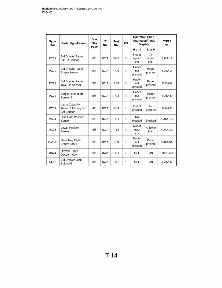
Interleaf EP5000/EP4000 TROUBLESHOOTING97.04.01
T-14
Sym-bol
Parts/Signal NameDis-play IC
No.PortNo.
I/O
Operation Char-acteristics/Panel
DisplayCN/PJ
No.Page
H or 1 L or 0
PC193rd Drawer PaperLift-Up Sensor
6/8 IC1A PG3 Not atupperlimit
Atupperlimit
PJ6A-12
PC203rd Drawer PaperEmpty Sensor
5/8 IC1A PC0 Paper
notpresent
Paperpresent
PJ6A-2
PC213rd Drawer PaperTake-Up Sensor
5/8 IC1A PE3 Paper
notpresent
Paperpresent
PJ6A-9
PC22Vertical TransportSensor 4
5/8 IC1A PC2 Paper
notpresent
Paperpresent
PJ6A-5
PC31Large Capacity Toner Collecting BoxSet Sensor
4/8 IC2A PC3 Out of
positionIn
positionPJ2A-2
PC34Shift Gate PositionSensor
5/8 IC1A PC1 Un-
blocked
BlockedPJ4A-1B
PC35Lower Position Sensor
6/8 IC2A PB3 Not atlowerlimit
At lowerlimit
PJ4A-2A
PWB-EMain Tray PaperEmpty Board
5/8 IC1A PF3 Paper
notpresent
Paperpresent
PJ4A-6A
UN21Drawer Paper Descent Key
6/8 IC2A PC2 OFF ON PJ4A-10A
SL413rd Drawer Lock Solenoid
6/8 IC2A PA1 OFF ON PJ5A-5
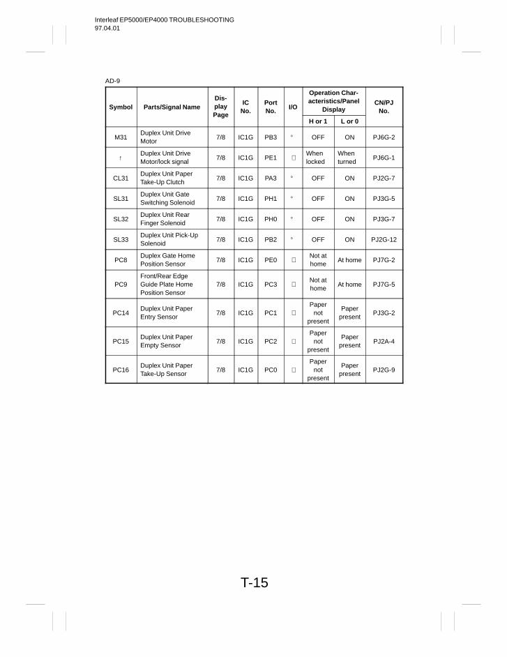
Interleaf EP5000/EP4000 TROUBLESHOOTING97.04.01
T-15
AD-9
Symbol Parts/Signal NameDis-play IC
No.PortNo.
I/O
Operation Char-acteristics/Panel
DisplayCN/PJ
No.Page
H or 1 L or 0
M31Duplex Unit Drive Motor
7/8 IC1G PB3 OFF ON PJ6G-2
↑Duplex Unit Drive Motor/lock signal
7/8 IC1G PE1 Whenlocked
Whenturned
PJ6G-1
CL31Duplex Unit PaperTake-Up Clutch
7/8 IC1G PA3 OFF ON PJ2G-7
SL31Duplex Unit GateSwitching Solenoid
7/8 IC1G PH1 OFF ON PJ3G-5
SL32Duplex Unit Rear Finger Solenoid
7/8 IC1G PH0 OFF ON PJ3G-7
SL33Duplex Unit Pick-UpSolenoid
7/8 IC1G PB2 OFF ON PJ2G-12
PC8Duplex Gate HomePosition Sensor
7/8 IC1G PE0 Not athome
At home PJ7G-2
PC9Front/Rear EdgeGuide Plate HomePosition Sensor
7/8 IC1G PC3 Not athome
At home PJ7G-5
PC14Duplex Unit PaperEntry Sensor
7/8 IC1G PC1 Paper
notpresent
Paperpresent
PJ3G-2
PC15Duplex Unit PaperEmpty Sensor
7/8 IC1G PC2 Paper
notpresent
Paperpresent
PJ2A-4
PC16Duplex Unit PaperTake-Up Sensor
7/8 IC1G PC0 Paper
notpresent
Paperpresent
PJ2G-9
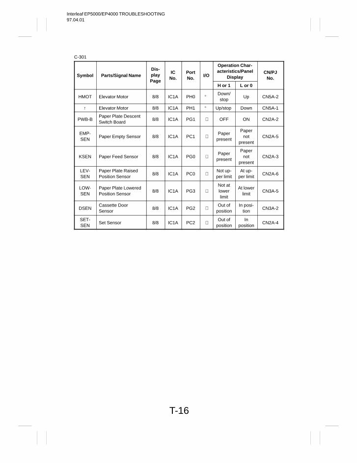
Interleaf EP5000/EP4000 TROUBLESHOOTING97.04.01
T-16
C-301
Symbol Parts/Signal NameDis-play IC
No.PortNo.
I/O
Operation Char-acteristics/Panel
DisplayCN/PJ
No.Page
H or 1 L or 0
HMOT Elevator Motor 8/8 IC1A PH0 Down/stop
Up CN5A-2
↑ Elevator Motor 8/8 IC1A PH1 Up/stop Down CN5A-1
PWB-BPaper Plate DescentSwitch Board
8/8 IC1A PG1 OFF ON CN2A-2
EMP-SEN
Paper Empty Sensor 8/8 IC1A PC1 Paper
present
Papernot
presentCN2A-5
KSEN Paper Feed Sensor 8/8 IC1A PG0 Paper
present
Papernot
presentCN2A-3
LEV-SEN
Paper Plate RaisedPosition Sensor
8/8 IC1A PC0 Not up-per limit
At up-per limit
CN2A-6
LOW-SEN
Paper Plate LoweredPosition Sensor
8/8 IC1A PG3 Not atlowerlimit
At lowerlimit
CN3A-5
DSENCassette Door Sensor
8/8 IC1A PG2 Out of
positionIn posi-
tionCN3A-2
SET-SEN
Set Sensor 8/8 IC1A PC2 Out of
positionIn
positionCN2A-4
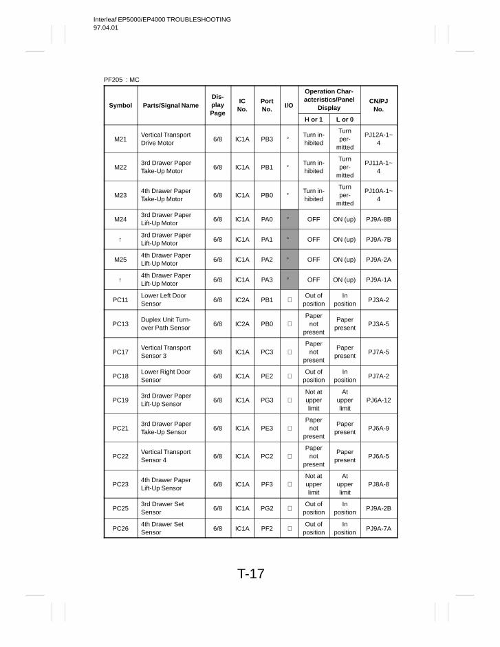
Interleaf EP5000/EP4000 TROUBLESHOOTING97.04.01
T-17
PF205 : MC
Symbol Parts/Signal NameDis-play IC
No.PortNo.
I/O
Operation Char-acteristics/Panel
DisplayCN/PJ
No.Page
H or 1 L or 0
M21Vertical TransportDrive Motor
6/8 IC1A PB3 Turn in-hibited
Turnper-
mitted
PJ12A-1~4
M223rd Drawer PaperTake-Up Motor
6/8 IC1A PB1 Turn in-hibited
Turnper-
mitted
PJ11A-1~4
M234th Drawer PaperTake-Up Motor
6/8 IC1A PB0 Turn in-hibited
Turnper-
mitted
PJ10A-1~4
M243rd Drawer PaperLift-Up Motor
6/8 IC1A PA0 OFF ON (up) PJ9A-8B
↑3rd Drawer PaperLift-Up Motor
6/8 IC1A PA1 OFF ON (up) PJ9A-7B
M254th Drawer PaperLift-Up Motor
6/8 IC1A PA2 OFF ON (up) PJ9A-2A
↑4th Drawer PaperLift-Up Motor
6/8 IC1A PA3 OFF ON (up) PJ9A-1A
PC11Lower Left DoorSensor
6/8 IC2A PB1 Out of
positionIn
positionPJ3A-2
PC13Duplex Unit Turn-over Path Sensor
6/8 IC2A PB0 Paper
notpresent
Paperpresent
PJ3A-5
PC17Vertical TransportSensor 3
6/8 IC1A PC3 Paper
notpresent
Paperpresent
PJ7A-5
PC18Lower Right DoorSensor
6/8 IC1A PE2 Out of
positionIn
positionPJ7A-2
PC193rd Drawer PaperLift-Up Sensor
6/8 IC1A PG3 Not atupperlimit
Atupperlimit
PJ6A-12
PC213rd Drawer PaperTake-Up Sensor
6/8 IC1A PE3 Paper
notpresent
Paperpresent
PJ6A-9
PC22Vertical TransportSensor 4
6/8 IC1A PC2 Paper
notpresent
Paperpresent
PJ6A-5
PC234th Drawer PaperLift-Up Sensor
6/8 IC1A PF3 Not atupperlimit
Atupperlimit
PJ8A-8
PC253rd Drawer Set Sensor
6/8 IC1A PG2 Out of
positionIn
positionPJ9A-2B
PC264th Drawer Set Sensor
6/8 IC1A PF2 Out of
positionIn
positionPJ9A-7A
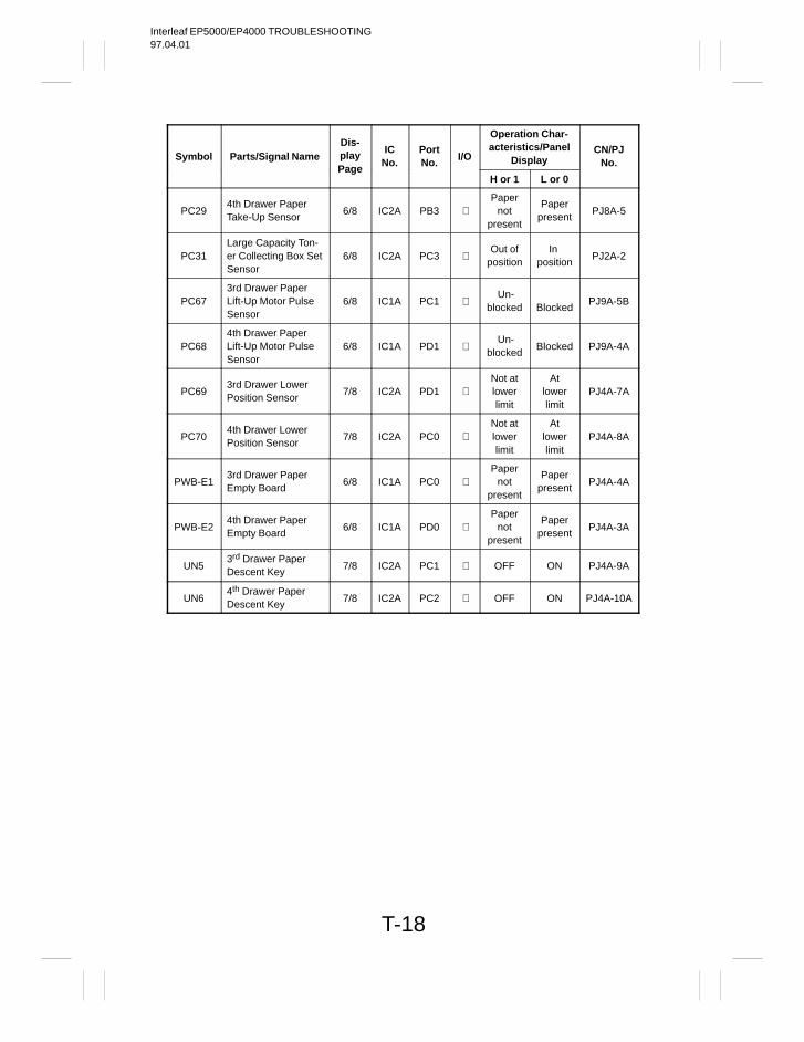
Interleaf EP5000/EP4000 TROUBLESHOOTING97.04.01
T-18
Symbol Parts/Signal NameDis-play IC
No.PortNo.
I/O
Operation Char-acteristics/Panel
DisplayCN/PJ
No.Page
H or 1 L or 0
PC294th Drawer PaperTake-Up Sensor
6/8 IC2A PB3 Paper
notpresent
Paperpresent
PJ8A-5
PC31Large Capacity Ton-er Collecting Box SetSensor
6/8 IC2A PC3 Out of
positionIn
positionPJ2A-2
PC673rd Drawer PaperLift-Up Motor PulseSensor
6/8 IC1A PC1 Un-
blocked
BlockedPJ9A-5B
PC684th Drawer PaperLift-Up Motor PulseSensor
6/8 IC1A PD1 Un-
blockedBlocked PJ9A-4A
PC693rd Drawer LowerPosition Sensor
7/8 IC2A PD1 Not atlowerlimit
Atlowerlimit
PJ4A-7A
PC704th Drawer LowerPosition Sensor
7/8 IC2A PC0 Not atlowerlimit
Atlowerlimit
PJ4A-8A
PWB-E13rd Drawer PaperEmpty Board
6/8 IC1A PC0 Paper
notpresent
Paperpresent
PJ4A-4A
PWB-E24th Drawer PaperEmpty Board
6/8 IC1A PD0 Paper
notpresent
Paperpresent
PJ4A-3A
UN53rd Drawer PaperDescent Key
7/8 IC2A PC1 OFF ON PJ4A-9A
UN64th Drawer PaperDescent Key
7/8 IC2A PC2 OFF ON PJ4A-10A
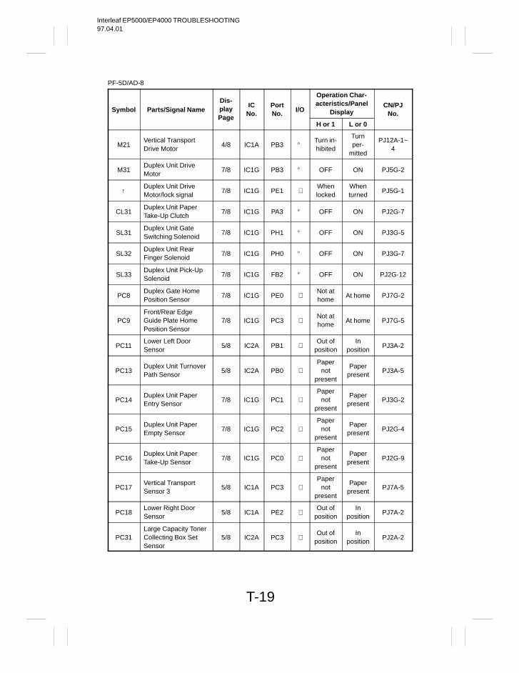
Interleaf EP5000/EP4000 TROUBLESHOOTING97.04.01
T-19
PF-5D/AD-8
Symbol Parts/Signal NameDis-play IC
No.PortNo.
I/O
Operation Char-acteristics/Panel
DisplayCN/PJ
No.Page
H or 1 L or 0
M21Vertical TransportDrive Motor
4/8 IC1A PB3 Turn in-hibited
Turnper-
mitted
PJ12A-1~4
M31Duplex Unit Drive Motor
7/8 IC1G PB3 OFF ON PJ5G-2
↑Duplex Unit Drive Motor/lock signal
7/8 IC1G PE1 Whenlocked
Whenturned
PJ5G-1
CL31Duplex Unit PaperTake-Up Clutch
7/8 IC1G PA3 OFF ON PJ2G-7
SL31Duplex Unit GateSwitching Solenoid
7/8 IC1G PH1 OFF ON PJ3G-5
SL32Duplex Unit Rear Finger Solenoid
7/8 IC1G PH0 OFF ON PJ3G-7
SL33Duplex Unit Pick-UpSolenoid
7/8 IC1G FB2 OFF ON PJ2G-12
PC8Duplex Gate HomePosition Sensor
7/8 IC1G PE0 Not athome
At home PJ7G-2
PC9Front/Rear EdgeGuide Plate HomePosition Sensor
7/8 IC1G PC3 Not athome
At home PJ7G-5
PC11Lower Left Door Sensor
5/8 IC2A PB1 Out of
positionIn
positionPJ3A-2
PC13Duplex Unit TurnoverPath Sensor
5/8 IC2A PB0 Paper
notpresent
Paperpresent
PJ3A-5
PC14Duplex Unit PaperEntry Sensor
7/8 IC1G PC1 Paper
notpresent
Paperpresent
PJ3G-2
PC15Duplex Unit PaperEmpty Sensor
7/8 IC1G PC2 Paper
notpresent
Paperpresent
PJ2G-4
PC16Duplex Unit PaperTake-Up Sensor
7/8 IC1G PC0 Paper
notpresent
Paperpresent
PJ2G-9
PC17Vertical TransportSensor 3
5/8 IC1A PC3 Paper
notpresent
Paperpresent
PJ7A-5
PC18Lower Right DoorSensor
5/8 IC1A PE2 Out of
positionIn
positionPJ7A-2
PC31Large Capacity TonerCollecting Box SetSensor
5/8 IC2A PC3 Out of
positionIn
positionPJ2A-2
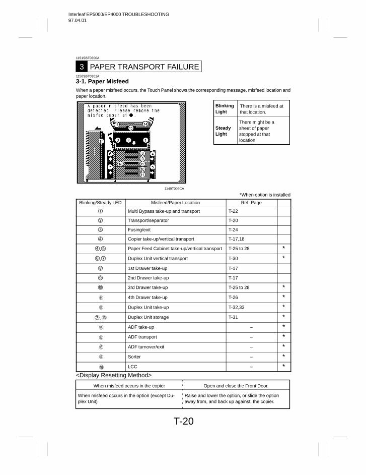
Interleaf EP5000/EP4000 TROUBLESHOOTING97.04.01
T-20
1151SBT0300A
PAPER TRANSPORT FAILURE31156SBT0301A
3-1. Paper MisfeedWhen a paper misfeed occurs, the Touch Panel shows the corresponding message, misfeed location andpaper location.
BlinkingLight
There is a misfeed atthat location.
SteadyLight
There might be asheet of paperstopped at thatlocation.
1149T002CA
*When option is installed
Blinking/Steady LED Misfeed/Paper Location Ref. Page
Multi Bypass take-up and transport T-22
Transport/separator T-20
Fusing/exit T-24
Copier take-up/vertical transport T-17,18
, Paper Feed Cabinet take-up/vertical transport T-25 to 28 *
, Duplex Unit vertical transport T-30 *
1st Drawer take-up T-17
2nd Drawer take-up T-17
3rd Drawer take-up T-25 to 28 *4th Drawer take-up T-26 *Duplex Unit take-up T-32,33 *
, Duplex Unit storage T-31 *ADF take-up – *ADF transport – *ADF turnover/exit – *Sorter – *LCC – *
<Display Resetting Method>
When misfeed occurs in the option (except Du-plex Unit)
When misfeed occurs in the copier Open and close the Front Door.
Raise and lower the option, or slide the optionaway from, and back up against, the copier.
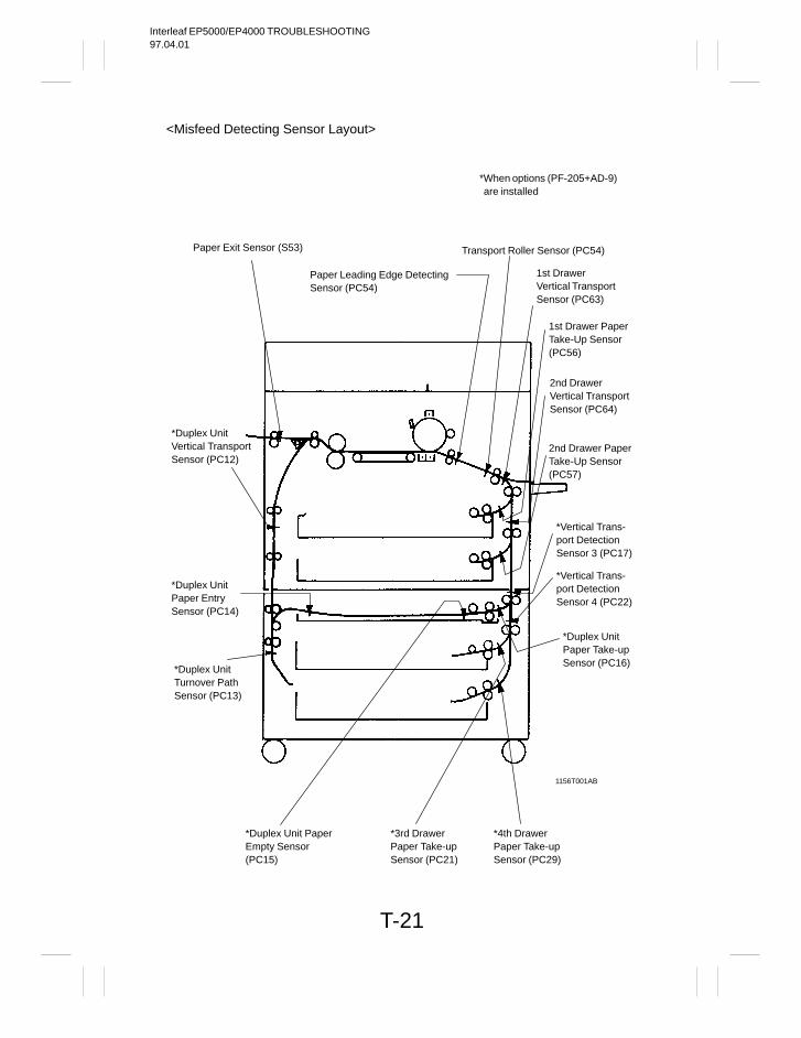
Interleaf EP5000/EP4000 TROUBLESHOOTING97.04.01
T-21
<Misfeed Detecting Sensor Layout>
Paper Exit Sensor (S53)
*When options (PF-205+AD-9)are installed
*Duplex UnitVertical TransportSensor (PC12)
*Duplex UnitPaper EntrySensor (PC14)
*Duplex UnitTurnover PathSensor (PC13)
*Duplex Unit PaperEmpty Sensor(PC15)
Paper Leading Edge DetectingSensor (PC54)
*3rd DrawerPaper Take-upSensor (PC21)
Transport Roller Sensor (PC54)
1st Drawer PaperTake-Up Sensor(PC56)
2nd DrawerVertical TransportSensor (PC64)
2nd Drawer PaperTake-Up Sensor(PC57)
*Vertical Trans-port DetectionSensor 3 (PC17)
*Vertical Trans-port DetectionSensor 4 (PC22)
*Duplex UnitPaper Take-upSensor (PC16)
*4th DrawerPaper Take-upSensor (PC29)
1156T001AB
1st DrawerVertical TransportSensor (PC63)
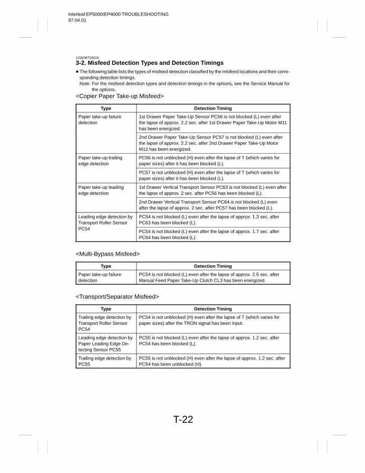
Interleaf EP5000/EP4000 TROUBLESHOOTING97.04.01
T-22
1156SBT0302A
3-2. Misfeed Detection Types and Detection Timings The following table lists the types of misfeed detection classified by the misfeed locations and their corre-
sponding detection timings.Note: For the misfeed detection types and detection timings in the options, see the Service Manual for
the options.
<Copier Paper Take-up Misfeed>
Type Detection Timing
Paper take-up failuredetection
1st Drawer Paper Take-Up Sensor PC56 is not blocked (L) even afterthe lapse of approx. 2.2 sec. after 1st Drawer Paper Take-Up Motor M11has been energized.
2nd Drawer Paper Take-Up Sensor PC57 is not blocked (L) even afterthe lapse of approx. 2.2 sec. after 2nd Drawer Paper Take-Up MotorM12 has been energized.
Paper take-up trailingedge detection
PC56 is not unblocked (H) even after the lapse of T (which varies forpaper sizes) after it has been blocked (L).
PC57 is not unblocked (H) even after the lapse of T (which varies forpaper sizes) after it has been blocked (L).
Paper take-up leadingedge detection
1st Drawer Vertical Transport Sensor PC63 is not blocked (L) even afterthe lapse of approx. 2 sec. after PC56 has been blocked (L).
2nd Drawer Vertical Transport Sensor PC64 is not blocked (L) evenafter the lapse of approx. 2 sec. after PC57 has been blocked (L).
Leading edge detection byTransport Roller Sensor
PC54 is not blocked (L) even after the lapse of approx. 1.3 sec. afterPC63 has been blocked (L).
PC54PC54 is not blocked (L) even after the lapse of approx. 1.7 sec. afterPC64 has been blocked (L).
<Multi-Bypass Misfeed>
Type Detection Timing
Paper take-up failuredetection
PC54 is not blocked (L) even after the lapse of approx. 2.5 sec. afterManual Feed Paper Take-Up Clutch CL3 has been energized.
<Transport/Separator Misfeed>
Type Detection Timing
Trailing edge detection byTransport Roller SensorPC54
PC54 is not unblocked (H) even after the lapse of T (which varies forpaper sizes) after the TRON signal has been input.
Leading edge detection byPaper Leading Edge De-tecting Sensor PC55
PC55 is not blocked (L) even after the lapse of approx. 1.2 sec. afterPC54 has been blocked (L).
Trailing edge detection byPC55
PC55 is not unblocked (H) even after the lapse of approx. 1.2 sec. afterPC54 has been unblocked (H).

Interleaf EP5000/EP4000 TROUBLESHOOTING97.04.01
T-23
<Fusing/Exit Misfeed>
Type Detection Timing
Leading edge detection byPaper Exit Switch S53
S53 is not deactuated even after the lapse of approx. 2 sec. after theTRON signal has been input.
Trailing edge detection byS53
S53 is not actuated even after the lapse of approx. 2.5 sec. after PC55has been unblocked (H).
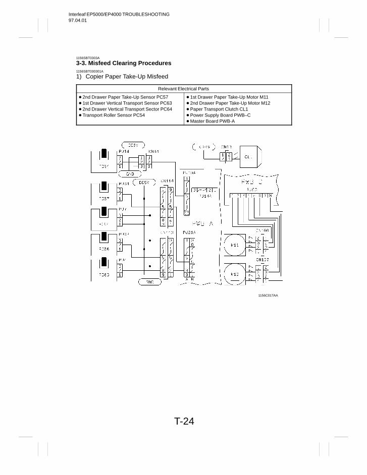
Interleaf EP5000/EP4000 TROUBLESHOOTING97.04.01
T-24
1156SBT0303A
3-3. Misfeed Clearing Procedures1156SBT030301A
1) Copier Paper Take-Up Misfeed
Relevant Electrical Parts
2nd Drawer Paper Take-Up Sensor PC57 1st Drawer Vertical Transport Sensor PC63 2nd Drawer Vertical Transport Sector PC64 Transport Roller Sensor PC54
1st Drawer Paper Take-Up Motor M11 2nd Drawer Paper Take-Up Motor M12 Paper Transport Clutch CL1 Power Supply Board PWB–C Master Board PWB-A
1156C01TAA
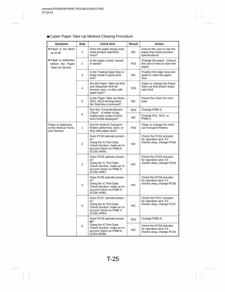
Interleaf EP5000/EP4000 TROUBLESHOOTING97.04.01
T-25
Copier Paper Take-Up Misfeed Clearing Procedure
Symptom Step Check Item Result Action
Paper is not takenup at all. 1
Does the paper being usedmeet product specifica-tions?
NOInstruct the user to use thepaper that meets productspecifications.
Paper is stationarybefore the PaperTake-Up Sensor.
2Is the paper curled, waved,or damp? YES
Change the paper. Instructthe user in how to store thepaper.
3Is the Trailing Edge Stop orEdge Guide in good posi-tion?
NOPosition the edge stop andguide to meet the papersize.
4
Are the Paper Take-Up Rolland Separator Roll de-formed, worn, or dirty withpaper dust?
YES
Clean or change the PaperTake-Up Roll and/or Sepa-rator Roll.
5Is the Paper Take-Up Motor(M11, M12) turning whenthe Start key is pressed?
NOCheck the motor for over-load.
Run the “Controller/Board YES Change PWB-A.
6Check.” Is either of themalfunction codes C032Aand C032B displayed? NO
Change M11, M12, orPWB-C.
Paper is stationaryat the Vertical Trans-port Section.
1Are the Vertical TransportRollers deformed, worn, ordirty with paper dust?
YESClean or change the Verti-cal Transport Rollers.
2
Does PC63 operate proper-ly?Using the IC Port DataCheck function, make an in-put port check on PWB-A(IC3A) APB6.
NO
Check the PC63 actuatorfor operation and, if itchecks okay, change PC63.
3
Does PC64 operate proper-ly?Using the IC Port DataCheck function, make an in-put port check on PWB-A(IC3A) APB7.
NO
Check the PC64 actuatorfor operation and, if itchecks okay, change PC64.
4
Does PC56 operate proper-ly?Using the IC Port DataCheck function, make an in-put port check on PWB-A(IC3A) APB3.
NO
Check the PC56 actuatorfor operation and, if itchecks okay, change PC56.
5
Does PC57 operate proper-ly?Using the IC Port DataCheck function, make an in-put port check on PWB-A(IC3A) APB4.
NO
Check the PC57 actuatorfor operation and, if itchecks okay, change PC57.
Does PC54 operate proper-ly?
YES Change PWB-A.
6
ly?Using the IC Port DataCheck function, make an in-put port check on PWB-A(IC5A) BPB6.
NOCheck the PC54 actuatorfor operation and, if itchecks okay, change PC54.
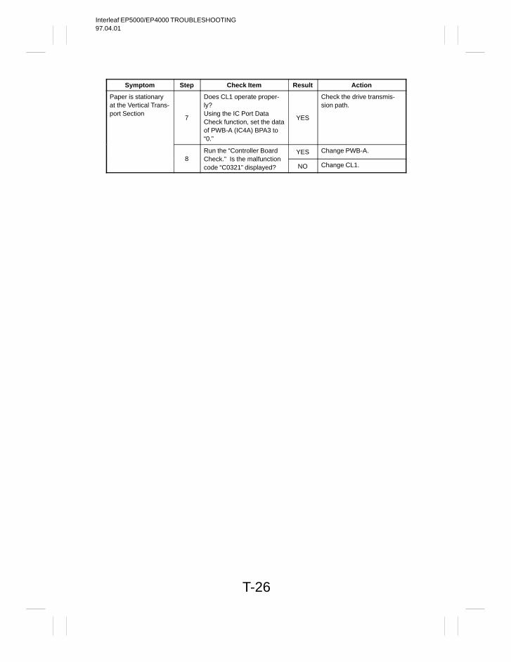
Interleaf EP5000/EP4000 TROUBLESHOOTING97.04.01
T-26
Symptom Step Check Item Result Action
Paper is stationaryat the Vertical Trans-port Section
7
Does CL1 operate proper-ly?Using the IC Port DataCheck function, set the dataof PWB-A (IC4A) BPA3 to“0.”
YES
Check the drive transmis-sion path.
Run the “Controller Board YES Change PWB-A.8 Check.” Is the malfunction
code “C0321” displayed? NO Change CL1.
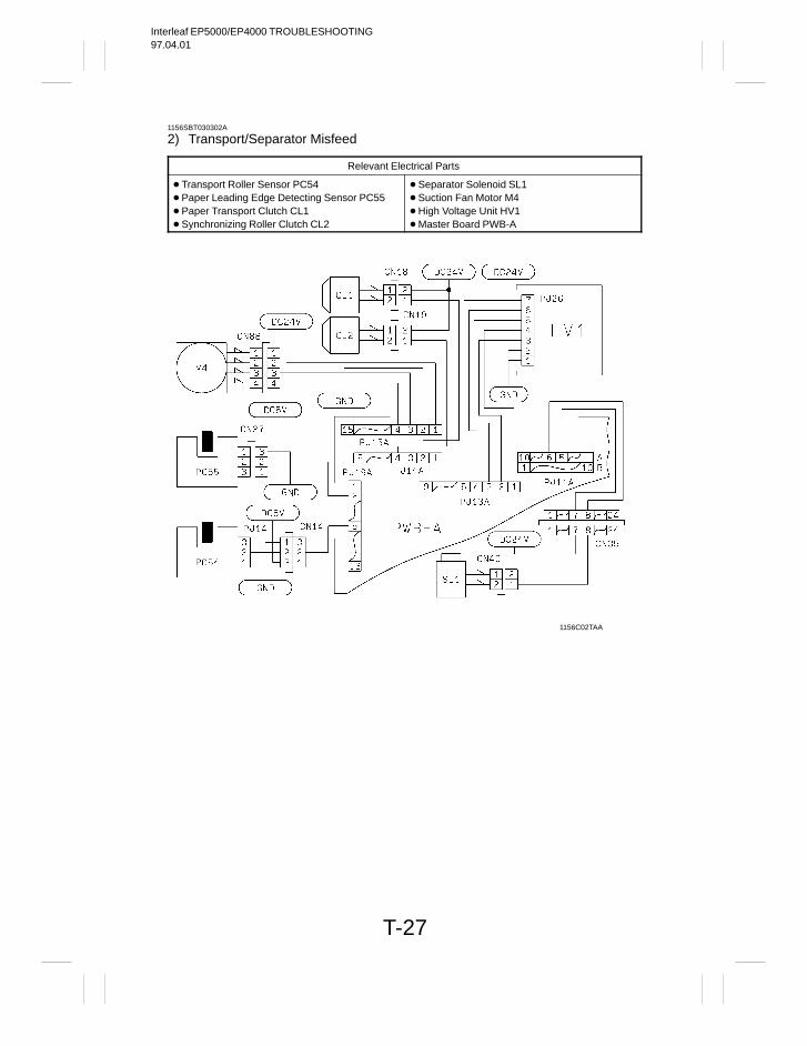
Interleaf EP5000/EP4000 TROUBLESHOOTING97.04.01
T-27
1156SBT030302A
2) Transport/Separator Misfeed
Relevant Electrical Parts
Transport Roller Sensor PC54 Paper Leading Edge Detecting Sensor PC55 Paper Transport Clutch CL1 Synchronizing Roller Clutch CL2
Separator Solenoid SL1 Suction Fan Motor M4 High Voltage Unit HV1 Master Board PWB-A
1156C02TAA
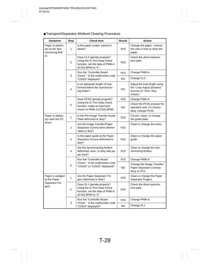
Interleaf EP5000/EP4000 TROUBLESHOOTING97.04.01
T-28
Transport/Separator Misfeed Clearing Procedure
Symptom Step Check Item Result Action
Paper is station-ary at the Syn-chronizing Roll-
1Is the paper curled, waved ordamp? YES
Change the paper. Instructthe user in how to store thepaper.
er.
2
Does CL2 operate properly?Using the IC Port Data Checkfunction, set the data of PWB-A(IC4A) BPA4 to “0.”
YES
Check the drive transmis-sion path.
Run the “Controller Board YES Change PWB-A.3 Check.” Is the malfunction code
“C0320” displayed? NO Change CL2.
4
Is an adequate length of loopformed before the Synchroniz-ing Roller?
NO
Adjust the loop length usingthe “Loop Adjust (Drawer)”function of “Tech. Rep.Choice.”
Does PC55 operate properly? YES Change PWB-A.
5Using the IC Port Data Checkfunction, make an input portcheck on PWB-A (IC5A) BPB5.
NOCheck the PC55 actuator foroperation and, if it checksokay, change PC55.
Paper is station-ary near the PC
1Is the Pre-Image Transfer GuidePlate deformed or dirty?
YESCorrect, clean, or changethe guide plate.
Drum.
2Are the Image Transfer/PaperSeparator Corona wires deterio-rated or dirty?
YESClean or change the wires.
3Is the paper guide at the PaperSeparator Corona deformed ordirty?
YESClean or change the paperguide.
4Are the Synchronizing Rollersdeformed, worn, or dirty with pa-per dust?
YESClean or change the Syn-chronizing Rollers.
Run the “Controller Board YES Change PWB-A.
5Check.” Is the malfunction code“C031D” or ”C031E” displayed? NO
Change the Image Transfer/Paper Separator CoronasAssy or HV1.
Paper is wedgedat the Paper
1Are the Paper Separator Fin-gers deformed or dirty?
YESClean or change the PaperSeparator Fingers.
Separator Fin-gers.
2
Does SL1 operate properly?Using the IC Port Data Checkfunction, set the data of PWB-A(IC4A) BPA0 to “0.”
YES
Check the drive transmis-sion path.
Run the “Controller Board YES Change PWB-A.3 Check.” Is the malfunction code
“C0324” displayed? NO Change SL1.
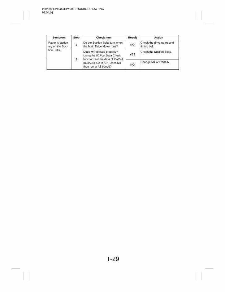
Interleaf EP5000/EP4000 TROUBLESHOOTING97.04.01
T-29
Symptom Step Check Item Result Action
Paper is station-ary on the Suc-
1Do the Suction Belts turn whenthe Main Drive Motor runs?
NOCheck the drive gears andtiming belt.
tion Belts.Does M4 operate properly?Using the IC Port Data Check YES
Check the Suction Belts.
2 function, set the data of PWB-A(IC4A) BPC2 to “0.” Does M4then run at full speed?
NOChange M4 or PWB-A.
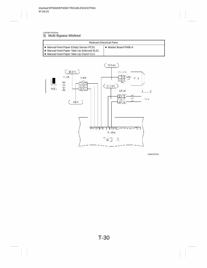
Interleaf EP5000/EP4000 TROUBLESHOOTING97.04.01
T-30
1156SBT030303A
3) Multi Bypass Misfeed
Relevant Electrical Parts
Manual Feed Paper Empty Sensor PC51 Manual Feed Paper Take-Up Solenoid SL51 Manual Feed Paper Take-Up Clutch CL3
Master Board PWB-A
1156C03TAA
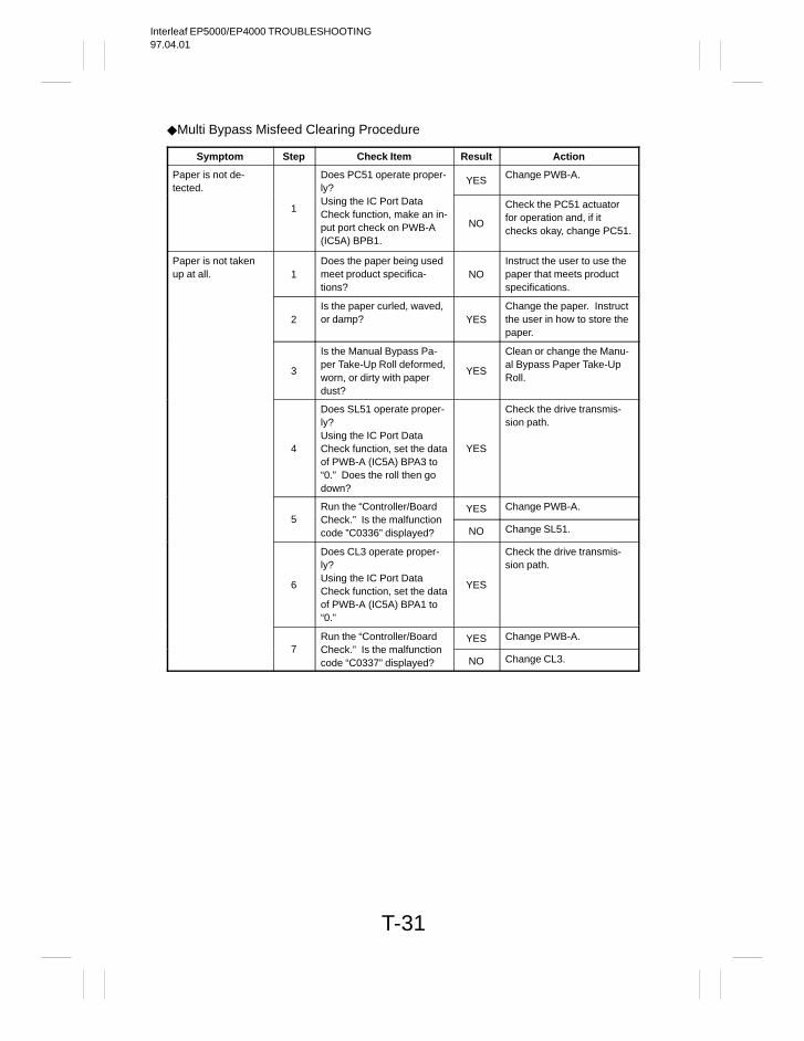
Interleaf EP5000/EP4000 TROUBLESHOOTING97.04.01
T-31
Multi Bypass Misfeed Clearing Procedure
Symptom Step Check Item Result Action
Paper is not de-tected.
Does PC51 operate proper-ly?
YES Change PWB-A.
1Using the IC Port DataCheck function, make an in-put port check on PWB-A(IC5A) BPB1.
NO
Check the PC51 actuatorfor operation and, if itchecks okay, change PC51.
Paper is not takenup at all. 1
Does the paper being usedmeet product specifica-tions?
NOInstruct the user to use thepaper that meets productspecifications.
2Is the paper curled, waved,or damp? YES
Change the paper. Instructthe user in how to store thepaper.
3
Is the Manual Bypass Pa-per Take-Up Roll deformed,worn, or dirty with paperdust?
YES
Clean or change the Manu-al Bypass Paper Take-UpRoll.
4
Does SL51 operate proper-ly?Using the IC Port DataCheck function, set the dataof PWB-A (IC5A) BPA3 to“0.” Does the roll then godown?
YES
Check the drive transmis-sion path.
Run the “Controller/Board YES Change PWB-A.5 Check.” Is the malfunction
code ”C0336” displayed? NO Change SL51.
6
Does CL3 operate proper-ly?Using the IC Port DataCheck function, set the dataof PWB-A (IC5A) BPA1 to“0.”
YES
Check the drive transmis-sion path.
Run the “Controller/Board YES Change PWB-A.7 Check.” Is the malfunction
code “C0337” displayed? NO Change CL3.
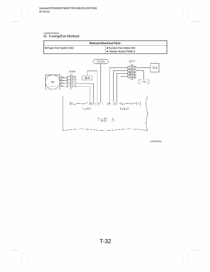
Interleaf EP5000/EP4000 TROUBLESHOOTING97.04.01
T-32
1156SBT030304A
4) Fusing/Exit Misfeed
Relevant Electrical Parts
Paper Exit Switch S53 Suction Fan Motor M4 Master Board PWB-A
1156C04TAA
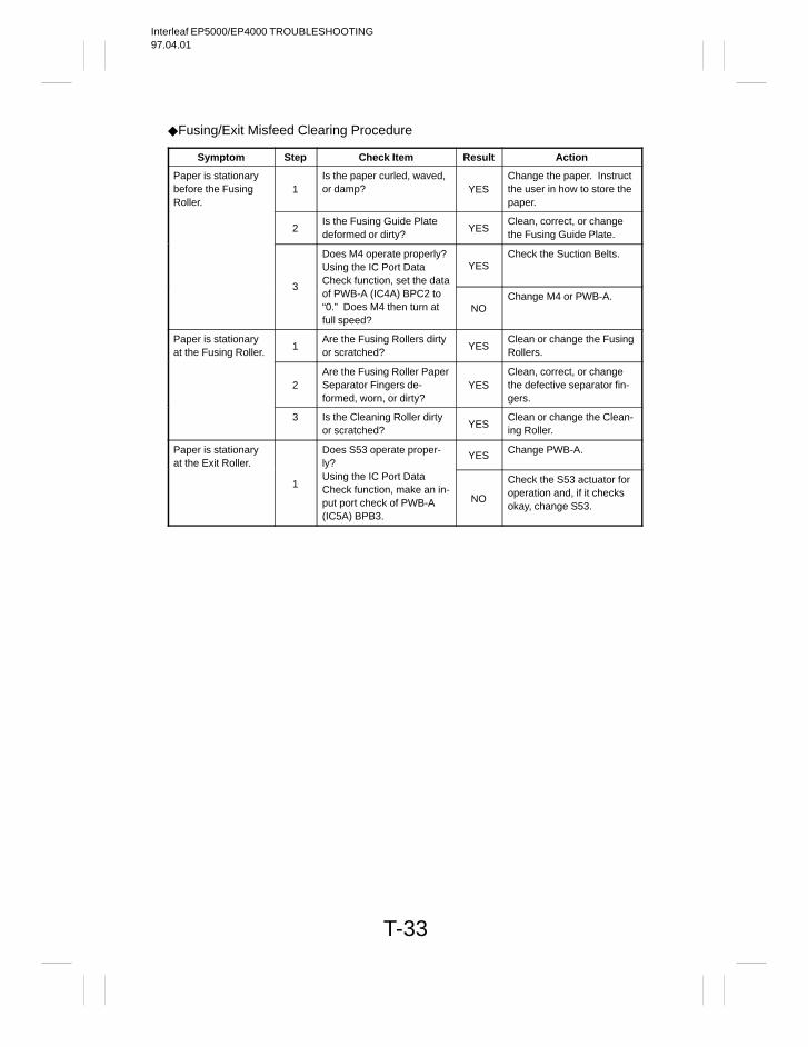
Interleaf EP5000/EP4000 TROUBLESHOOTING97.04.01
T-33
Fusing/Exit Misfeed Clearing Procedure
Symptom Step Check Item Result Action
Paper is stationarybefore the FusingRoller.
1Is the paper curled, waved,or damp? YES
Change the paper. Instructthe user in how to store thepaper.
2Is the Fusing Guide Platedeformed or dirty?
YESClean, correct, or changethe Fusing Guide Plate.
Does M4 operate properly?Using the IC Port DataCheck function, set the data
YESCheck the Suction Belts.
3of PWB-A (IC4A) BPC2 to“0.” Does M4 then turn atfull speed?
NOChange M4 or PWB-A.
Paper is stationaryat the Fusing Roller.
1Are the Fusing Rollers dirtyor scratched?
YESClean or change the FusingRollers.
2Are the Fusing Roller PaperSeparator Fingers de-formed, worn, or dirty?
YESClean, correct, or changethe defective separator fin-gers.
3 Is the Cleaning Roller dirtyor scratched?
YESClean or change the Clean-ing Roller.
Paper is stationaryat the Exit Roller.
Does S53 operate proper-ly?
YES Change PWB-A.
1Using the IC Port DataCheck function, make an in-put port check of PWB-A(IC5A) BPB3.
NO
Check the S53 actuator foroperation and, if it checksokay, change S53.
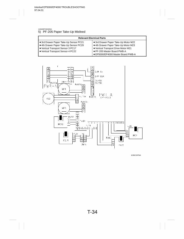
Interleaf EP5000/EP4000 TROUBLESHOOTING97.04.01
T-34
1156SBT030305A
5) PF-205 Paper Take-Up Misfeed
Relevant Electrical Parts
3rd Drawer Paper Take-Up Sensor PC21 4th Drawer Paper Take-Up Sensor PC29 Vertical Transport Sensor 3 PC17 Vertical Transport Sensor 4 PC22
3rd Drawer Paper Take-Up Motor M22 4th Drawer Paper Take-Up Motor M23 Vertical Transport Drive Motor M21 PF-205 Master Board PWB-A EP5000/EP4000 Master Board PWB-A
1156C24TAA
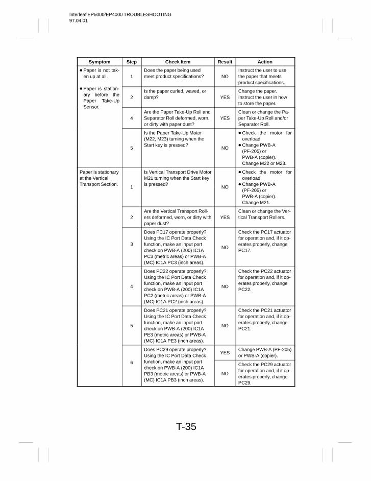
Interleaf EP5000/EP4000 TROUBLESHOOTING97.04.01
T-35
Symptom Step Check Item Result Action
Paper is not tak-en up at all. 1
Does the paper being usedmeet product specifications? NO
Instruct the user to usethe paper that meetsproduct specifications.
Paper is station-ary before thePaper Take-Up
2Is the paper curled, waved, ordamp? YES
Change the paper.Instruct the user in howto store the paper.
Sensor.
4Are the Paper Take-Up Roll andSeparator Roll deformed, worn,or dirty with paper dust?
YESClean or change the Pa-per Take-Up Roll and/orSeparator Roll.
Is the Paper Take-Up Motor(M22, M23) turning when theStart key is pressed?
Check the motor foroverload.
Change PWB-A5 NO
(PF-205) or PWB-A (copier).Change M22 or M23.
Paper is stationaryat the VerticalTransport Section.
Is Vertical Transport Drive MotorM21 turning when the Start keyis pressed?
Check the motor foroverload.
Change PWB-A1 NO
(PF-205) or PWB-A (copier).Change M21.
2Are the Vertical Transport Roll-ers deformed, worn, or dirty withpaper dust?
YESClean or change the Ver-tical Transport Rollers.
3
Does PC17 operate properly?Using the IC Port Data Checkfunction, make an input portcheck on PWB-A (200) IC1APC3 (metric areas) or PWB-A(MC) IC1A PC3 (inch areas).
NO
Check the PC17 actuatorfor operation and, if it op-erates properly, changePC17.
4
Does PC22 operate properly?Using the IC Port Data Checkfunction, make an input portcheck on PWB-A (200) IC1APC2 (metric areas) or PWB-A(MC) IC1A PC2 (inch areas).
NO
Check the PC22 actuatorfor operation and, if it op-erates properly, changePC22.
5
Does PC21 operate properly?Using the IC Port Data Checkfunction, make an input portcheck on PWB-A (200) IC1APE3 (metric areas) or PWB-A(MC) IC1A PE3 (inch areas).
NO
Check the PC21 actuatorfor operation and, if it op-erates properly, changePC21.
Does PC29 operate properly?Using the IC Port Data Check
YESChange PWB-A (PF-205)or PWB-A (copier).
6 function, make an input portcheck on PWB-A (200) IC1APB3 (metric areas) or PWB-A(MC) IC1A PB3 (inch areas).
NO
Check the PC29 actuatorfor operation and, if it op-erates properly, changePC29.
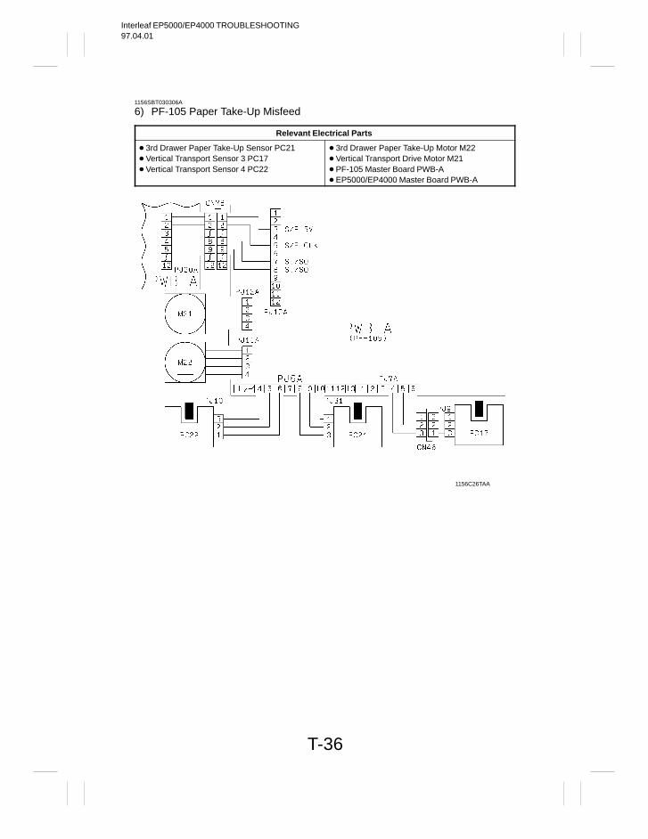
Interleaf EP5000/EP4000 TROUBLESHOOTING97.04.01
T-36
1156SBT030306A
6) PF-105 Paper Take-Up Misfeed
Relevant Electrical Parts
3rd Drawer Paper Take-Up Sensor PC21 Vertical Transport Sensor 3 PC17 Vertical Transport Sensor 4 PC22
3rd Drawer Paper Take-Up Motor M22 Vertical Transport Drive Motor M21 PF-105 Master Board PWB-A EP5000/EP4000 Master Board PWB-A
1156C26TAA
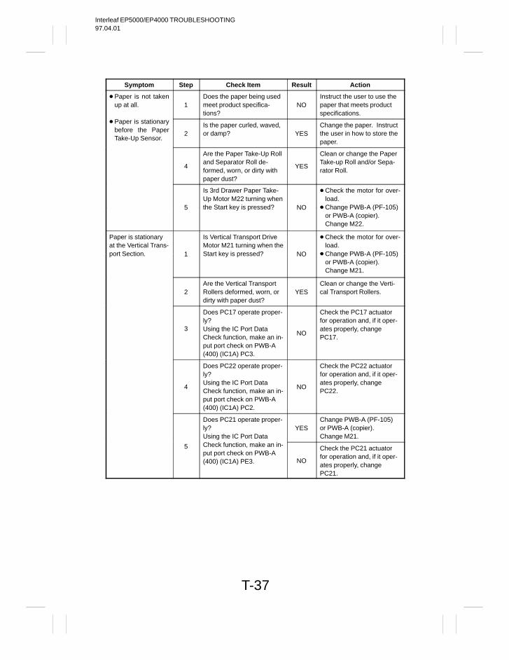
Interleaf EP5000/EP4000 TROUBLESHOOTING97.04.01
T-37
Symptom Step Check Item Result Action
Paper is not takenup at all. 1
Does the paper being usedmeet product specifica-tions?
NOInstruct the user to use thepaper that meets productspecifications.
Paper is stationarybefore the PaperTake-Up Sensor.
2Is the paper curled, waved,or damp? YES
Change the paper. Instructthe user in how to store thepaper.
4
Are the Paper Take-Up Rolland Separator Roll de-formed, worn, or dirty withpaper dust?
YES
Clean or change the PaperTake-up Roll and/or Sepa-rator Roll.
Is 3rd Drawer Paper Take-Up Motor M22 turning when
Check the motor for over-load.
5 the Start key is pressed? NO Change PWB-A (PF-105)or PWB-A (copier).Change M22.
Paper is stationaryat the Vertical Trans-
Is Vertical Transport DriveMotor M21 turning when the
Check the motor for over-load.
port Section. 1 Start key is pressed? NO Change PWB-A (PF-105)or PWB-A (copier).Change M21.
2Are the Vertical TransportRollers deformed, worn, ordirty with paper dust?
YESClean or change the Verti-cal Transport Rollers.
3
Does PC17 operate proper-ly?Using the IC Port DataCheck function, make an in-put port check on PWB-A(400) (IC1A) PC3.
NO
Check the PC17 actuatorfor operation and, if it oper-ates properly, changePC17.
4
Does PC22 operate proper-ly?Using the IC Port DataCheck function, make an in-put port check on PWB-A(400) (IC1A) PC2.
NO
Check the PC22 actuatorfor operation and, if it oper-ates properly, changePC22.
Does PC21 operate proper-ly?Using the IC Port Data
YESChange PWB-A (PF-105)or PWB-A (copier).Change M21.
5 Check function, make an in-put port check on PWB-A(400) (IC1A) PE3. NO
Check the PC21 actuatorfor operation and, if it oper-ates properly, changePC21.
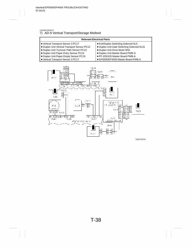
Interleaf EP5000/EP4000 TROUBLESHOOTING97.04.01
T-38
1156SBT030307A
7) AD-9 Vertical Transport/Storage Misfeed
Relevant Electrical Parts
Vertical Transport Sensor 3 PC17 Duplex Unit Vertical Transport Sensor PC12 Duplex Unit Turnover Path Sensor PC13 Duplex Unit Paper Entry Sensor PC14 Duplex Unit Paper Empty Sensor PC15 Vertical Transport Sensor 3 PC17
Exit/Duplex Switching Solenoid SL5 Duplex Unit Gate Switching Solenoid SL31 Duplex Unit Drive Motor M31 Duplex Unit Master Board PWB-G PF-205/105 Master Board PWB-A EP5000/EP4000 Master Board PWB-A
1156C30TAA
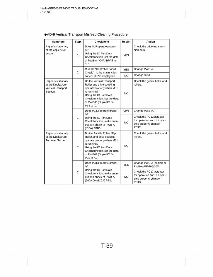
Interleaf EP5000/EP4000 TROUBLESHOOTING97.04.01
T-39
AD-9 Vertical Transport Misfeed Clearing Procedure
Symptom Step Check Item Result Action
Paper is stationaryat the copier exitsection.
1
Does SL5 operate proper-ly?Using the IC Port DataCheck function, set the dataof PWB-A (IC4A) BPA5 to“0.”
YES
Check the drive transmis-sion path.
Run the “Controller Board YES Change PWB-A.2 Check.” Is the malfunction
code “C0324” displayed? NO Change SL51.
Paper is stationaryat the Duplex UnitVertical TransportSection.
1
Do the Vertical TransportRoller and drive couplingoperate properly when M31is running?Using the IC Port DataCheck function, set the dataof PWB-G (Dup) (IC1G)PB3 to “0.”
NO
Check the gears, belts, androllers.
Does PC12 operate proper- YES Change PWB-A.
2
ly?Using the IC Port DataCheck function, make an in-put port check of PWB-A(IC5A) BPB0.
NO
Check the PC12 actuatorfor operation and, if it oper-ates properly, changePC12.
Paper is stationaryat the Duplex UnitTurnover Section.
1
Do the Paddle Roller, SlipRoller, and drive couplingoperate properly when M31is running?Using the IC Port DataCheck function, set the dataof PWB-G (Dup) (IC1G)PB3 to “0.”
NO
Check the gears, belts, androllers.
Does PC13 operate proper-ly?
YESChange PWB-A (copier) orPWB-A (PF-205/105).
2Using the IC Port DataCheck function, make an in-put port check of PWB-A(200/400) (IC2A) PB0.
NO
Check the PC13 actuatorfor operation and, if it oper-ates properly, changePC13.
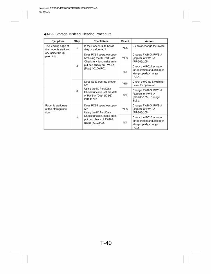
Interleaf EP5000/EP4000 TROUBLESHOOTING97.04.01
T-40
AD-9 Storage Misfeed Clearing Procedure
Symptom Step Check Item Result Action
The leading edge ofthe paper is station-
1Is the Paper Guide Mylardirty or deformed?
YESClean or change the mylar.
ary inside the Du-plex Unit.
Does PC14 operate proper-ly? Using the IC Port DataCheck function, make an in-
YESChange PWB-G, PWB-A(copier), or PWB-A(PF-205/105).
2 put port check on PWB-A(Dup) (IC1G) PC1.
NO
Check the PC14 actuatorfor operation and, if it oper-ates properly, changePC14.
Does SL31 operate proper-ly?
YESCheck the Gate SwitchingLever for operation.
3Using the IC Port DataCheck function, set the dataof PWB-A (Dup) (IC1G)PH1 to “0.”
NO
Change PWB-G, PWB-A(copier), or PWB-A(PF-205/105). ChangeSL31.
Paper is stationaryat the storage sec-tion.
Does PC15 operate proper-ly?Using the IC Port Data
YESChange PWB-G, PWB-A(copier), or PWB-A(PF-205/105).
1 Check function, make an in-put port check of PWB-A(Dup) (IC1G) C2. NO
Check the PC15 actuatorfor operation and, if it oper-ates properly, changePC15.
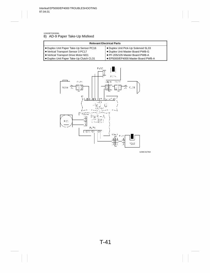
Interleaf EP5000/EP4000 TROUBLESHOOTING97.04.01
T-41
1156SBT030308A
8) AD-9 Paper Take-Up Misfeed
Relevant Electrical Parts
Duplex Unit Paper Take-Up Sensor PC16 Vertical Transport Sensor 3 PC17 Vertical Transport Drive Motor M21 Duplex Unit Paper Take-Up Clutch CL31
Duplex Unit Pick-Up Solenoid SL33 Duplex Unit Master Board PWB-G PF-205/105 Master Board PWB-A EP5000/EP4000 Master Board PWB-A
1156C31TAA
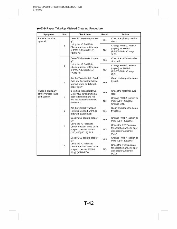
Interleaf EP5000/EP4000 TROUBLESHOOTING97.04.01
T-42
AD-9 Paper Take-Up Misfeed Clearing Procedure
Symptom Step Check Item Result Action
Paper is not takenup at all.
Does SL33 operate proper-ly?
YESCheck the pick-up mecha-nism.
1Using the IC Port DataCheck function, set the dataof PWB-A (Dup) (IC1G)PB2 to “0.”
NO
Change PWB-G, PWB-A(copier), or PWB-A(PF-205/105). ChangeSL33.
Does CL33 operate proper-ly?
YESCheck the drive transmis-sion path.
2Using the IC Port DataCheck function, set the dataof PWB-A (Dup) (IC1G)PA3 to “0.”
NO
Change PWB-G, PWB-A(copier), or PWB-A(PF-205/105). ChangeCL31.
3
Are the Take-Up Roll, FeedRoll, and Separator Roll de-formed, worn, or dirty withpaper dust?
YES
Clean or change the defec-tive roll.
Paper is stationaryat the Vertical Trans-
Is Vertical Transport DriveMotor M21 turning when a
YESCheck the motor for over-load.
port Section. 1 copy is taken up and fedinto the copier from the Du-plex Unit?
NOChange PWB-A (copier) orPWB-A (PF-205/105).Change M21.
2Are the Vertical TransportRollers deformed, worn, ordirty with paper dust?
YESClean or change the defec-tive roller.
Does PC17 operate proper-ly?
YESChange PWB-A (copier) orPWB-A (PF-205/105).
3Using the IC Port DataCheck function, make an in-put port check of PWB-A(200, 400) (IC1A) PC3.
NO
Check the PC17 actuatorfor operation and, if it oper-ates properly, changePC17.
Does PC16 operate proper-ly?
YESChange PWB-A (copier) orPWB-A (PF-205/105).
4Using the IC Port DataCheck function, make an in-put port check of PWB-A(Dup) (IC1G) PC0.
NO
Check the PC16 actuatorfor operation and, if it oper-ates properly, changePC16.
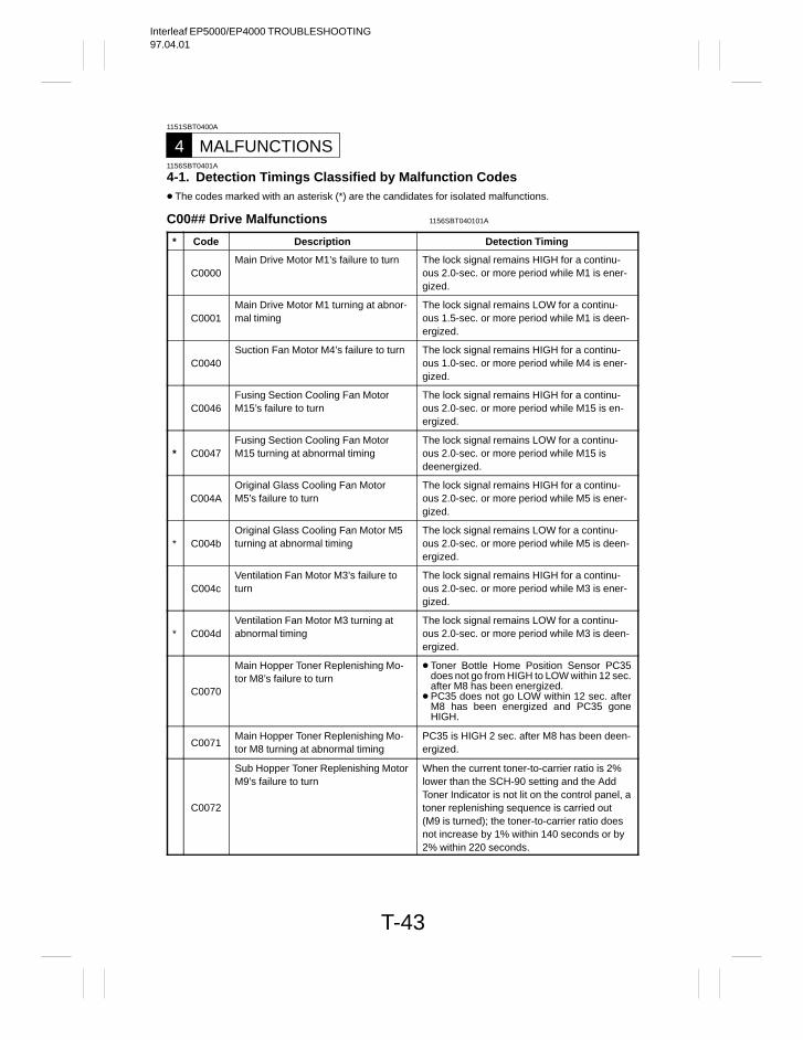
Interleaf EP5000/EP4000 TROUBLESHOOTING97.04.01
T-43
1151SBT0400A
MALFUNCTIONS41156SBT0401A
4-1. Detection Timings Classified by Malfunction Codes The codes marked with an asterisk (*) are the candidates for isolated malfunctions.
C00## Drive Malfunctions 1156SBT040101A
* Code Description Detection Timing
C0000Main Drive Motor M1’s failure to turn The lock signal remains HIGH for a continu-
ous 2.0-sec. or more period while M1 is ener-gized.
C0001Main Drive Motor M1 turning at abnor-mal timing
The lock signal remains LOW for a continu-ous 1.5-sec. or more period while M1 is deen-ergized.
C0040Suction Fan Motor M4’s failure to turn The lock signal remains HIGH for a continu-
ous 1.0-sec. or more period while M4 is ener-gized.
C0046Fusing Section Cooling Fan MotorM15’s failure to turn
The lock signal remains HIGH for a continu-ous 2.0-sec. or more period while M15 is en-ergized.
* C0047Fusing Section Cooling Fan MotorM15 turning at abnormal timing
The lock signal remains LOW for a continu-ous 2.0-sec. or more period while M15 isdeenergized.
C004AOriginal Glass Cooling Fan MotorM5’s failure to turn
The lock signal remains HIGH for a continu-ous 2.0-sec. or more period while M5 is ener-gized.
* C004bOriginal Glass Cooling Fan Motor M5turning at abnormal timing
The lock signal remains LOW for a continu-ous 2.0-sec. or more period while M5 is deen-ergized.
C004cVentilation Fan Motor M3’s failure toturn
The lock signal remains HIGH for a continu-ous 2.0-sec. or more period while M3 is ener-gized.
* C004dVentilation Fan Motor M3 turning atabnormal timing
The lock signal remains LOW for a continu-ous 2.0-sec. or more period while M3 is deen-ergized.
C0070
Main Hopper Toner Replenishing Mo-tor M8’s failure to turn
Toner Bottle Home Position Sensor PC35does not go from HIGH to LOW within 12 sec.after M8 has been energized.
PC35 does not go LOW within 12 sec. afterM8 has been energized and PC35 goneHIGH.
C0071Main Hopper Toner Replenishing Mo-tor M8 turning at abnormal timing
PC35 is HIGH 2 sec. after M8 has been deen-ergized.
C0072
Sub Hopper Toner Replenishing MotorM9’s failure to turn
When the current toner-to-carrier ratio is 2%lower than the SCH-90 setting and the AddToner Indicator is not lit on the control panel, atoner replenishing sequence is carried out(M9 is turned); the toner-to-carrier ratio doesnot increase by 1% within 140 seconds or by2% within 220 seconds.
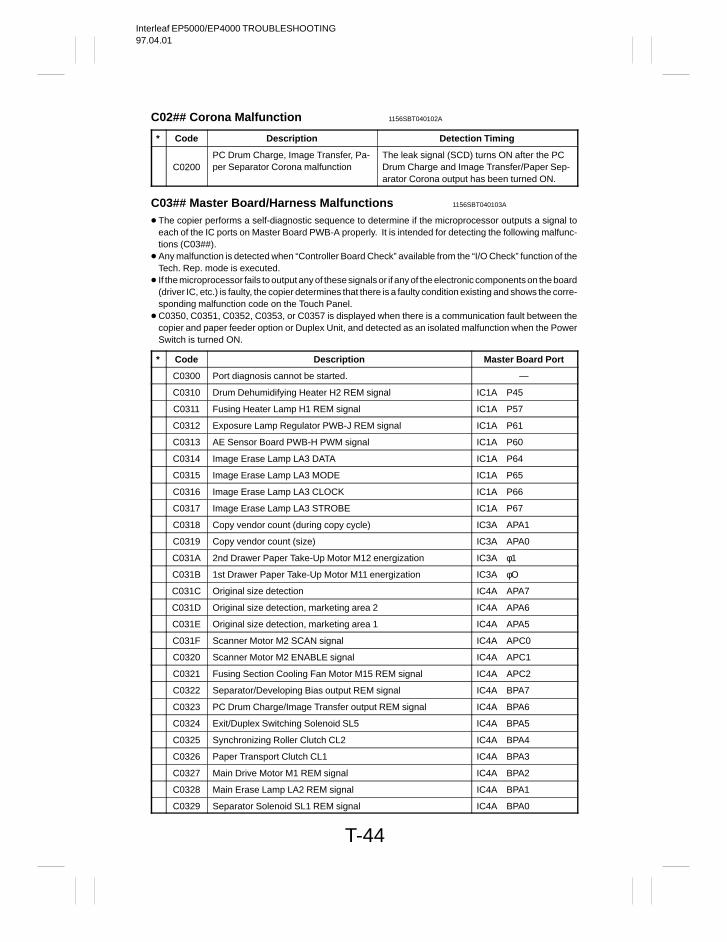
Interleaf EP5000/EP4000 TROUBLESHOOTING97.04.01
T-44
C02## Corona Malfunction 1156SBT040102A
* Code Description Detection Timing
C0200PC Drum Charge, Image Transfer, Pa-per Separator Corona malfunction
The leak signal (SCD) turns ON after the PCDrum Charge and Image Transfer/Paper Sep-arator Corona output has been turned ON.
C03## Master Board/Harness Malfunctions 1156SBT040103A
The copier performs a self-diagnostic sequence to determine if the microprocessor outputs a signal toeach of the IC ports on Master Board PWB-A properly. It is intended for detecting the following malfunc-tions (C03##).
Any malfunction is detected when “Controller Board Check” available from the “I/O Check” function of theTech. Rep. mode is executed.
If the microprocessor fails to output any of these signals or if any of the electronic components on the board(driver IC, etc.) is faulty, the copier determines that there is a faulty condition existing and shows the corre-sponding malfunction code on the Touch Panel.
C0350, C0351, C0352, C0353, or C0357 is displayed when there is a communication fault between thecopier and paper feeder option or Duplex Unit, and detected as an isolated malfunction when the PowerSwitch is turned ON.
* Code Description Master Board Port
C0300 Port diagnosis cannot be started. —
C0310 Drum Dehumidifying Heater H2 REM signal IC1A P45
C0311 Fusing Heater Lamp H1 REM signal IC1A P57
C0312 Exposure Lamp Regulator PWB-J REM signal IC1A P61
C0313 AE Sensor Board PWB-H PWM signal IC1A P60
C0314 Image Erase Lamp LA3 DATA IC1A P64
C0315 Image Erase Lamp LA3 MODE IC1A P65
C0316 Image Erase Lamp LA3 CLOCK IC1A P66
C0317 Image Erase Lamp LA3 STROBE IC1A P67
C0318 Copy vendor count (during copy cycle) IC3A APA1
C0319 Copy vendor count (size) IC3A APA0
C031A 2nd Drawer Paper Take-Up Motor M12 energization IC3A φ1
C031B 1st Drawer Paper Take-Up Motor M11 energization IC3A φO
C031C Original size detection IC4A APA7
C031D Original size detection, marketing area 2 IC4A APA6
C031E Original size detection, marketing area 1 IC4A APA5
C031F Scanner Motor M2 SCAN signal IC4A APC0
C0320 Scanner Motor M2 ENABLE signal IC4A APC1
C0321 Fusing Section Cooling Fan Motor M15 REM signal IC4A APC2
C0322 Separator/Developing Bias output REM signal IC4A BPA7
C0323 PC Drum Charge/Image Transfer output REM signal IC4A BPA6
C0324 Exit/Duplex Switching Solenoid SL5 IC4A BPA5
C0325 Synchronizing Roller Clutch CL2 IC4A BPA4
C0326 Paper Transport Clutch CL1 IC4A BPA3
C0327 Main Drive Motor M1 REM signal IC4A BPA2
C0328 Main Erase Lamp LA2 REM signal IC4A BPA1
C0329 Separator Solenoid SL1 REM signal IC4A BPA0
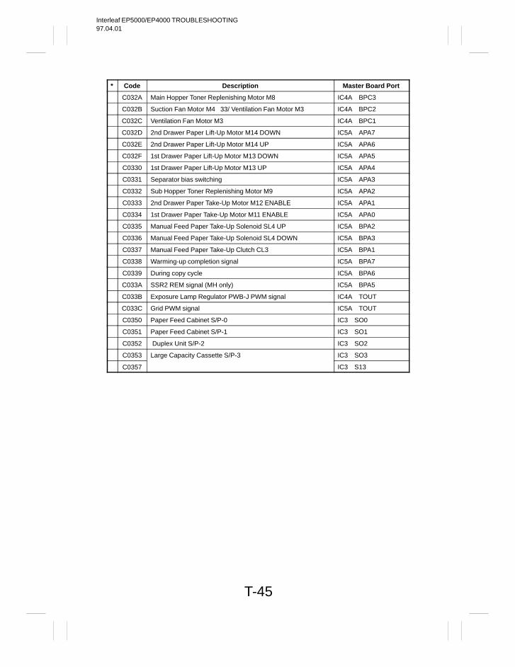
Interleaf EP5000/EP4000 TROUBLESHOOTING97.04.01
T-45
* Code Description Master Board Port
C032A Main Hopper Toner Replenishing Motor M8 IC4A BPC3
C032B Suction Fan Motor M4 33/ Ventilation Fan Motor M3 IC4A BPC2
C032C Ventilation Fan Motor M3 IC4A BPC1
C032D 2nd Drawer Paper Lift-Up Motor M14 DOWN IC5A APA7
C032E 2nd Drawer Paper Lift-Up Motor M14 UP IC5A APA6
C032F 1st Drawer Paper Lift-Up Motor M13 DOWN IC5A APA5
C0330 1st Drawer Paper Lift-Up Motor M13 UP IC5A APA4
C0331 Separator bias switching IC5A APA3
C0332 Sub Hopper Toner Replenishing Motor M9 IC5A APA2
C0333 2nd Drawer Paper Take-Up Motor M12 ENABLE IC5A APA1
C0334 1st Drawer Paper Take-Up Motor M11 ENABLE IC5A APA0
C0335 Manual Feed Paper Take-Up Solenoid SL4 UP IC5A BPA2
C0336 Manual Feed Paper Take-Up Solenoid SL4 DOWN IC5A BPA3
C0337 Manual Feed Paper Take-Up Clutch CL3 IC5A BPA1
C0338 Warming-up completion signal IC5A BPA7
C0339 During copy cycle IC5A BPA6
C033A SSR2 REM signal (MH only) IC5A BPA5
C033B Exposure Lamp Regulator PWB-J PWM signal IC4A TOUT
C033C Grid PWM signal IC5A TOUT
C0350 Paper Feed Cabinet S/P-0 IC3 SO0
C0351 Paper Feed Cabinet S/P-1 IC3 SO1
C0352 Duplex Unit S/P-2 IC3 SO2
C0353 Large Capacity Cassette S/P-3 IC3 SO3
C0357 IC3 S13
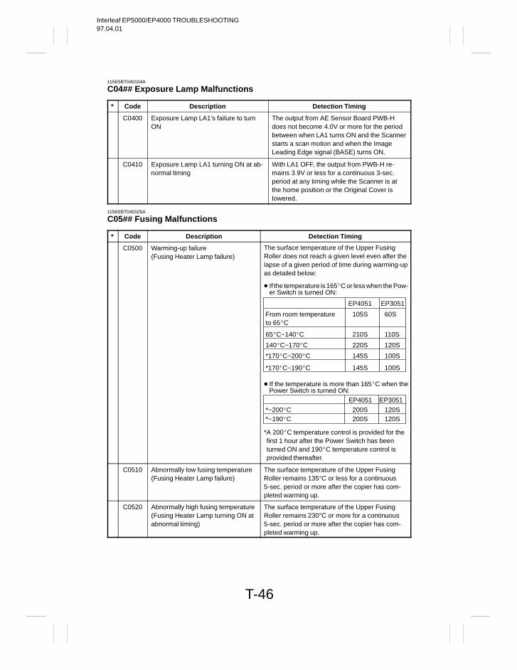
Interleaf EP5000/EP4000 TROUBLESHOOTING97.04.01
T-46
1156SBT040104A
C04## Exposure Lamp Malfunctions
* Code Description Detection Timing
C0400 Exposure Lamp LA1’s failure to turnON
The output from AE Sensor Board PWB-Hdoes not become 4.0V or more for the periodbetween when LA1 turns ON and the Scannerstarts a scan motion and when the ImageLeading Edge signal (BASE) turns ON.
C0410 Exposure Lamp LA1 turning ON at ab-normal timing
With LA1 OFF, the output from PWB-H re-mains 3.9V or less for a continuous 3-sec.period at any timing while the Scanner is atthe home position or the Original Cover islowered.
1156SBT040105A
C05## Fusing Malfunctions
* Code Description Detection Timing
C0500 Warming-up failure (Fusing Heater Lamp failure)
The surface temperature of the Upper FusingRoller does not reach a given level even after thelapse of a given period of time during warming-upas detailed below:
If the temperature is 165C or less when the Pow-er Switch is turned ON:
From room temperature 105S 60S to 65C
65C~140C 210S 110S
EP4051 EP3051
140C~170C 220S 120S
*170C~200C 145S 100S
*170C~190C 145S 100S
If the temperature is more than 165C when thePower Switch is turned ON:
EP4051 EP3051
*A 200C temperature control is provided for thefirst 1 hour after the Power Switch has beenturned ON and 190C temperature control isprovided thereafter.
*~200C 200S 120S *~190C 200S 120S
C0510 Abnormally low fusing temperature(Fusing Heater Lamp failure)
The surface temperature of the Upper FusingRoller remains 135°C or less for a continuous5-sec. period or more after the copier has com-pleted warming up.
C0520 Abnormally high fusing temperature(Fusing Heater Lamp turning ON atabnormal timing)
The surface temperature of the Upper FusingRoller remains 230°C or more for a continuous5-sec. period or more after the copier has com-pleted warming up.
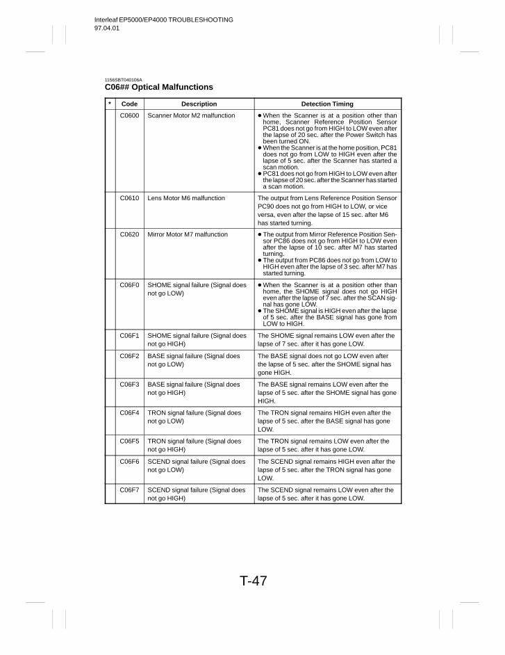
Interleaf EP5000/EP4000 TROUBLESHOOTING97.04.01
T-47
1156SBT040106A
C06## Optical Malfunctions
* Code Description Detection Timing
C0600 Scanner Motor M2 malfunction When the Scanner is at a position other thanhome, Scanner Reference Position SensorPC81 does not go from HIGH to LOW even afterthe lapse of 20 sec. after the Power Switch hasbeen turned ON.
When the Scanner is at the home position, PC81does not go from LOW to HIGH even after thelapse of 5 sec. after the Scanner has started ascan motion.
PC81 does not go from HIGH to LOW even afterthe lapse of 20 sec. after the Scanner has starteda scan motion.
C0610 Lens Motor M6 malfunction The output from Lens Reference Position SensorPC90 does not go from HIGH to LOW, or viceversa, even after the lapse of 15 sec. after M6has started turning.
C0620 Mirror Motor M7 malfunction The output from Mirror Reference Position Sen-sor PC86 does not go from HIGH to LOW evenafter the lapse of 10 sec. after M7 has startedturning.
The output from PC86 does not go from LOW toHIGH even after the lapse of 3 sec. after M7 hasstarted turning.
C06F0 SHOME signal failure (Signal doesnot go LOW)
When the Scanner is at a position other thanhome, the SHOME signal does not go HIGHeven after the lapse of 7 sec. after the SCAN sig-nal has gone LOW.
The SHOME signal is HIGH even after the lapseof 5 sec. after the BASE signal has gone fromLOW to HIGH.
C06F1 SHOME signal failure (Signal doesnot go HIGH)
The SHOME signal remains LOW even after thelapse of 7 sec. after it has gone LOW.
C06F2 BASE signal failure (Signal doesnot go LOW)
The BASE signal does not go LOW even afterthe lapse of 5 sec. after the SHOME signal hasgone HIGH.
C06F3 BASE signal failure (Signal doesnot go HIGH)
The BASE signal remains LOW even after thelapse of 5 sec. after the SHOME signal has goneHIGH.
C06F4 TRON signal failure (Signal doesnot go LOW)
The TRON signal remains HIGH even after thelapse of 5 sec. after the BASE signal has goneLOW.
C06F5 TRON signal failure (Signal doesnot go HIGH)
The TRON signal remains LOW even after thelapse of 5 sec. after it has gone LOW.
C06F6 SCEND signal failure (Signal doesnot go LOW)
The SCEND signal remains HIGH even after thelapse of 5 sec. after the TRON signal has goneLOW.
C06F7 SCEND signal failure (Signal doesnot go HIGH)
The SCEND signal remains LOW even after thelapse of 5 sec. after it has gone LOW.
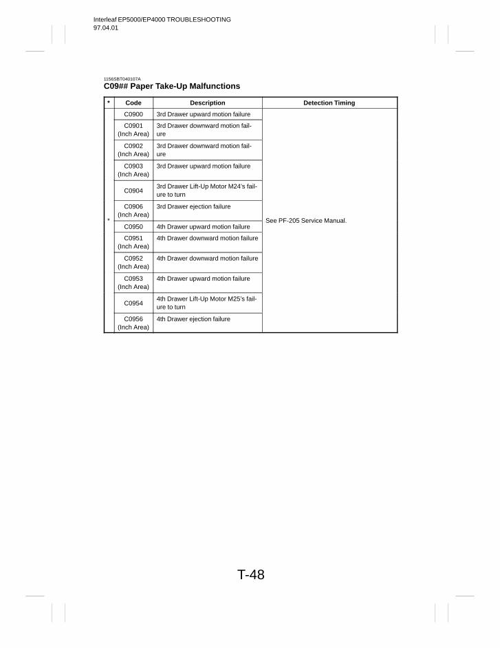
Interleaf EP5000/EP4000 TROUBLESHOOTING97.04.01
T-48
1156SBT040107A
C09## Paper Take-Up Malfunctions
* Code Description Detection Timing
C0900 3rd Drawer upward motion failure
C0901(Inch Area)
3rd Drawer downward motion fail-ure
C0902(Inch Area)
3rd Drawer downward motion fail-ure
C0903(Inch Area)
3rd Drawer upward motion failure
C09043rd Drawer Lift-Up Motor M24’s fail-ure to turn
C0906(Inch Area)
3rd Drawer ejection failure
*C0950 4th Drawer upward motion failure
See PF-205 Service Manual.
C0951(Inch Area)
4th Drawer downward motion failure
C0952(Inch Area)
4th Drawer downward motion failure
C0953(Inch Area)
4th Drawer upward motion failure
C09544th Drawer Lift-Up Motor M25’s fail-ure to turn
C0956(Inch Area)
4th Drawer ejection failure
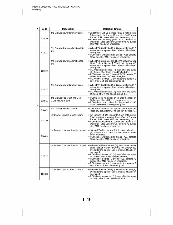
Interleaf EP5000/EP4000 TROUBLESHOOTING97.04.01
T-49
* Code Description Detection Timing
C0910
2nd Drawer upward motion failure 2nd Drawer Lift-Up Sensor PC66 is not blocked(L) even after the lapse of 5 sec. after 2nd DrawerPaper Lift-Up Motor M14 has been energized.
PC66 is not blocked (L) even if 2nd Drawer Lift-Up Motor Pulse Sensor PC68 detects 75 pulsesafter M14 has been energized.
C0911
2nd Drawer downward motion fail-ure
When PC66 is blocked (L), it is not unblocked (H)even after the lapse of 5 sec. after M14 has beenenergized.
PC66 is not unblocked (H) even if PC68 detects10 pulses after M14 has been energized.
C0912
2nd Drawer downward motion fail-ure
When PC66 is unblocked (H), 2nd Drawer LowerLimit Position Sensor PC70 is not blocked (L)even after the lapse of 5 sec. after M14 has beenenergized.
PC70 is not unblocked (H) even after the lapseof 1.5 sec. after it has been blocked (L).
PC70 is not blocked (L) even if PC68 detects 75pulses after M14 has been energized.
PC70 is not blocked (L) even after the lapse of 2sec. after M14 has been energized.
C0913
2nd Drawer upward motion failure When PC70 is blocked (L), it is not unblocked (H)even after the lapse of 5 sec. after M14 has beenenergized.
PC70 is not unblocked (H) even after the lapseof 2 sec. after it has been blocked (L).
*
C0914
2nd Drawer Paper Lift–Up MotorM14’s failure to turn
PC68 detects no pulses even after the lapse of500 msec. after M14 has been energized.
PC68 detects no pulses for the period of 200msec. while M14 is being energized.*
C0916 2nd Drawer ejection failure The 2nd Drawer is not ejected even after thelapse of 2 sec. after PC70 has been blocked (L).
C0920
1st Drawer upward motion failure 1st Drawer Lift-Up Sensor PC65 is not blocked(L) even after the lapse of 5 sec. after 1st DrawerPaper Lift-Up Motor M13 has been energized.
PC65 is not blocked (L) even if 1st Drawer Lift-Up Motor Pulse Sensor PC67 detects 75 pulsesafter M13 has been energized.
C0921
1st Drawer downward motion failure When PC65 is blocked (L), it is not unblocked(H) even after the lapse of 5 sec. after M13 hasbeen energized.
PC65 is not unblocked (H) even if PC67 detects10 pulses after M13 has been energized.
C0922
1st Drawer downward motion failure When PC65 is unblocked (H), 1st Drawer LowerLimit Position Sensor PC69 is not blocked (L)even after the lapse of 5 sec. after M13 has beenenergized.
PC69 is not unblocked (H) even after the lapseof 1.5 sec. after it has been blocked (L).
PC69 is not blocked (L) even if PC67 detects 75pulses after M13 has been energized.
PC69 is not blocked (L) even after the lapse of 2sec. after M13 has been energized.
C0923
1st Drawer upward motion failure When PC69 is blocked (L), it is not unblocked (H)even after the lapse of 5 sec. after M13 has beenenergized.
PC69 is not unblocked (H) even after the lapseof 2 sec. after it has been blocked (L).

Interleaf EP5000/EP4000 TROUBLESHOOTING97.04.01
T-50
* Code Description Detection Timing
*C0924
1st Drawer Paper Lift–Up MotorM13’s failure to turn
PC67 detects no pulses even after the lapse of500 msec. after M13 has been energized.
PC67 detects no pulses for the period of 200msec. while M13 is being energized.
C0926 1st Drawer ejection failure The 1st Drawer is not ejected even after thelapse of 2 sec. after PC69 has been blocked (L).
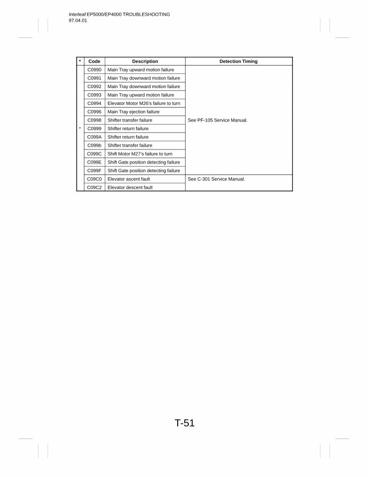
Interleaf EP5000/EP4000 TROUBLESHOOTING97.04.01
T-51
* Code Description Detection Timing
C0990 Main Tray upward motion failure
C0991 Main Tray downward motion failure
C0992 Main Tray downward motion failure
C0993 Main Tray upward motion failure
C0994 Elevator Motor M26’s failure to turn
C0996 Main Tray ejection failure
C0998 Shifter transfer failure See PF-105 Service Manual.
* C0999 Shifter return failure
C099A Shifter return failure
C099b Shifter transfer failure
C099C Shift Motor M27’s failure to turn
C099E Shift Gate position detecting failure
C099F Shift Gate position detecting failure
C09C0 Elevator ascent fault See C-301 Service Manual.
C09C2 Elevator descent fault
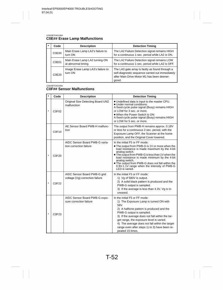
Interleaf EP5000/EP4000 TROUBLESHOOTING97.04.01
T-52
1156SBT040108A
C0E## Erase Lamp Malfunctions
* Code Description Detection Timing
C0E00Main Erase Lamp LA2’s failure toturn ON
The LA2 Failure Detection signal remains HIGHfor a continuous 1-sec. period while LA2 is ON.
C0E01Main Erase Lamp LA2 turning ONat abnormal timing
The LA2 Failure Detection signal remains LOWfor a continuous 1-sec. period while LA2 is OFF.
C0E20
Image Erase Lamp LA3’s failure toturn ON
The LA3 gate array is faulty as found through aself-diagnostic sequence carried out immediatelyafter Main Drive Motor M1 has been deener-gized.
1156SBT040109A
C0F## Sensor Malfunctions
* Code Description Detection Timing
* C0F02
Original Size Detecting Board UN2malfunction
Undefined data is input to the master CPU. Under normal conditions:A fixed-cycle pulse signal (Busy) remains HIGHor LOW for 3 sec. or more. When the Power Switch is ON:A fixed-cycle pulse signal (Busy) remains HIGHor LOW for 5 sec. or more.
C0F10
AE Sensor Board PWB-H malfunc-tion
The output from PWB-H remains approx. 0.18Vor less for a continuous 2-sec. period, with theExposure Lamp OFF, the Scanner at the homeposition, and the Original Cover lowered.
* C0F20
AIDC Sensor Board PWB-G varia-tion correction failure
In the initial F5 or FF mode: The output from PWB-G is 1V or more when the
load resistance is made maximum by the 4-bitanalog switch.
The output from PWB-G is less than 1V when theload resistance is made minimum by the 4-bitanalog switch.
The output from PWB-G does not fall within the0.9V-1.1V range when the intensity of PWB-GLED is varied.
* C0F22
AIDC Sensor Board PWB-G gridvoltage (Vg) correction failure
In the initial F5 or FF mode:1) Vg of 580V is output.2) A solid black pattern is produced and thePWB-G output is sampled.3) If the average is less than 4.3V, Vg is in-creased.
* C0F23
AIDC Sensor Board PWB-G expo-sure correction failure
In the initial F5 or FF mode:1) The Exposure Lamp is turned ON with58V.2) A halftone pattern is produced and thePWB-G output is sampled.3) If the average does not fall within the tar-get range, the exposure level is varied.4) The average does not fall within the targetrange even after steps 1) to 3) have been re-peated 15 times.
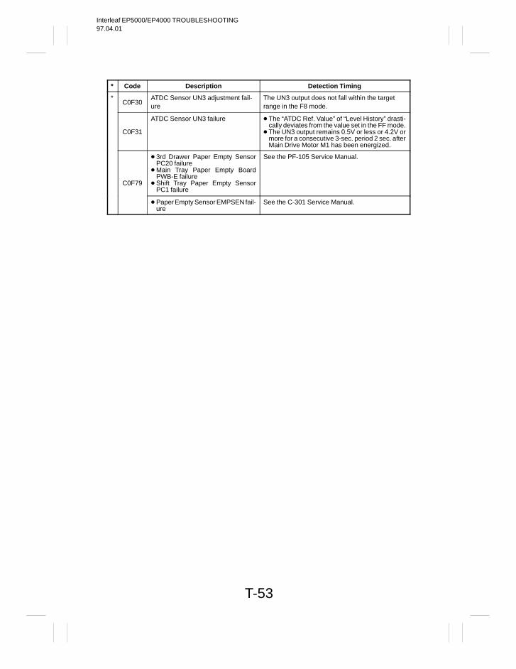
Interleaf EP5000/EP4000 TROUBLESHOOTING97.04.01
T-53
* Code Description Detection Timing
*C0F30
ATDC Sensor UN3 adjustment fail-ure
The UN3 output does not fall within the targetrange in the F8 mode.
C0F31
ATDC Sensor UN3 failure The “ATDC Ref. Value” of “Level History” drasti-cally deviates from the value set in the FF mode.
The UN3 output remains 0.5V or less or 4.2V ormore for a consecutive 3-sec. period 2 sec. afterMain Drive Motor M1 has been energized.
C0F79
3rd Drawer Paper Empty SensorPC20 failure
Main Tray Paper Empty BoardPWB-E failure
Shift Tray Paper Empty SensorPC1 failure
See the PF-105 Service Manual.
Paper Empty Sensor EMPSEN fail-ure
See the C-301 Service Manual.
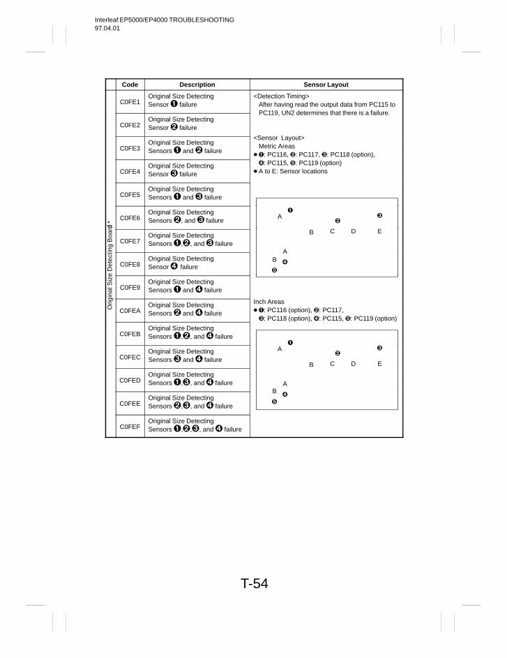
Interleaf EP5000/EP4000 TROUBLESHOOTING97.04.01
T-54
Code Description Sensor Layout
C0FE1Original Size DetectingSensor failure
<Detection Timing>After having read the output data from PC115 to
C0FE2Original Size DetectingSensor failure
PC119, UN2 determines that there is a failure.
C0FE3Original Size DetectingSensors and failure
<Sensor Layout>Metric Areas
: PC116, : PC117, : PC118 (option),
C0FE4Original Size DetectingSensor failure
: PC115, : PC119 (option) A to E: Sensor locations
C0FE5Original Size DetectingSensors and failure
d * C0FE6
Original Size DetectingSensors , and failure
A
ng B
oard
C0FE7Original Size DetectingSensors ,, and failure
B C D E
Det
ecti
C0FE8Original Size DetectingSensor failure
A
B
inal
Siz
e
C0FE9Original Size DetectingSensors and failure
Orig
C0FEAOriginal Size DetectingSensors and failure
Inch Areas: PC116 (option), : PC117, : PC118 (option), : PC115, : PC119 (option)
C0FEBOriginal Size DetectingSensors ,, and failure
C0FECOriginal Size DetectingSensors and failure
A
B C D E
C0FEDOriginal Size DetectingSensors ,, and failure A
C0FEEOriginal Size DetectingSensors ,, and failure
B
C0FEFOriginal Size DetectingSensors ,,, and failure
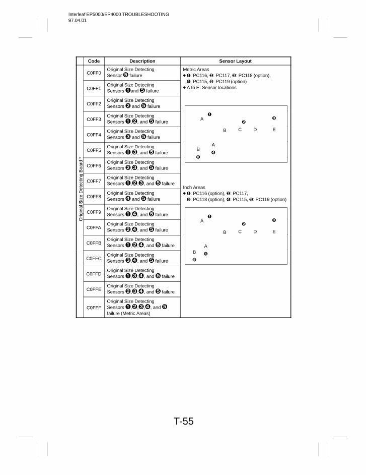
Interleaf EP5000/EP4000 TROUBLESHOOTING97.04.01
T-55
Code Description Sensor Layout
C0FF0Original Size DetectingSensor failure
Metric Areas: PC116, : PC117, : PC118 (option),
C0FF1Original Size DetectingSensors and failure
: PC115, : PC119 (option) A to E: Sensor locations
C0FF2Original Size DetectingSensors and failure
C0FF3Original Size DetectingSensors ,, and failure
A
C0FF4Original Size DetectingSensors and failure
B C D E
C0FF5Original Size DetectingSensors ,, and failure
AB
Boa
rd *
C0FF6Original Size DetectingSensors ,, and failure
tect
ing
C0FF7Original Size DetectingSensors ,,, and failure
Siz
e D
e
C0FF8Original Size DetectingSensors and failure
Inch Areas: PC116 (option), : PC117, : PC118 (option), : PC115, : PC119 (option)
rigin
al S
C0FF9Original Size DetectingSensors ,, and failure
O
C0FFAOriginal Size DetectingSensors ,, and failure
A
B C D E
C0FFBOriginal Size DetectingSensors ,,, and failure A
C0FFCOriginal Size DetectingSensors ,, and failure
B
C0FFDOriginal Size DetectingSensors ,,, and failure
C0FFEOriginal Size DetectingSensors ,,, and failure
C0FFFOriginal Size DetectingSensors ,,,, and failure (Metric Areas)
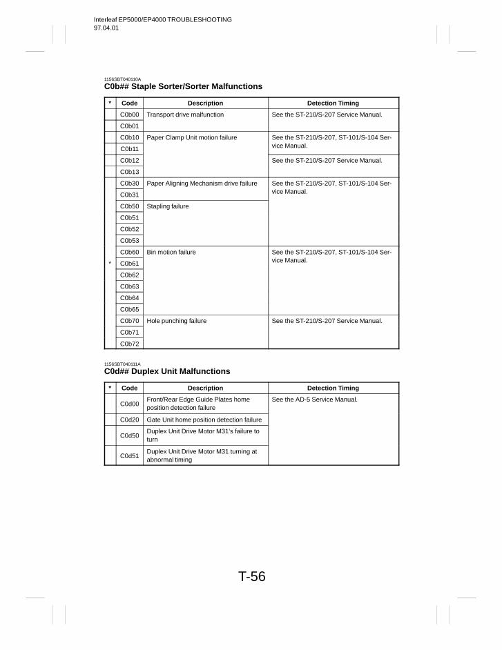
Interleaf EP5000/EP4000 TROUBLESHOOTING97.04.01
T-56
1156SBT040110A
C0b## Staple Sorter/Sorter Malfunctions
* Code Description Detection Timing
C0b00 Transport drive malfunction See the ST-210/S-207 Service Manual.
C0b01
C0b10 Paper Clamp Unit motion failure See the ST-210/S-207, ST-101/S-104 Ser-
C0b11 vice Manual.
C0b12 See the ST-210/S-207 Service Manual.
C0b13
C0b30 Paper Aligning Mechanism drive failure See the ST-210/S-207, ST-101/S-104 Ser-
C0b31 vice Manual.
C0b50 Stapling failure
C0b51
C0b52
C0b53
C0b60 Bin motion failure See the ST-210/S-207, ST-101/S-104 Ser-
* C0b61 vice Manual.
C0b62
C0b63
C0b64
C0b65
C0b70 Hole punching failure See the ST-210/S-207 Service Manual.
C0b71
C0b72
1156SBT040111A
C0d## Duplex Unit Malfunctions
* Code Description Detection Timing
C0d00Front/Rear Edge Guide Plates homeposition detection failure
See the AD-5 Service Manual.
C0d20 Gate Unit home position detection failure
C0d50Duplex Unit Drive Motor M31’s failure toturn
C0d51Duplex Unit Drive Motor M31 turning atabnormal timing
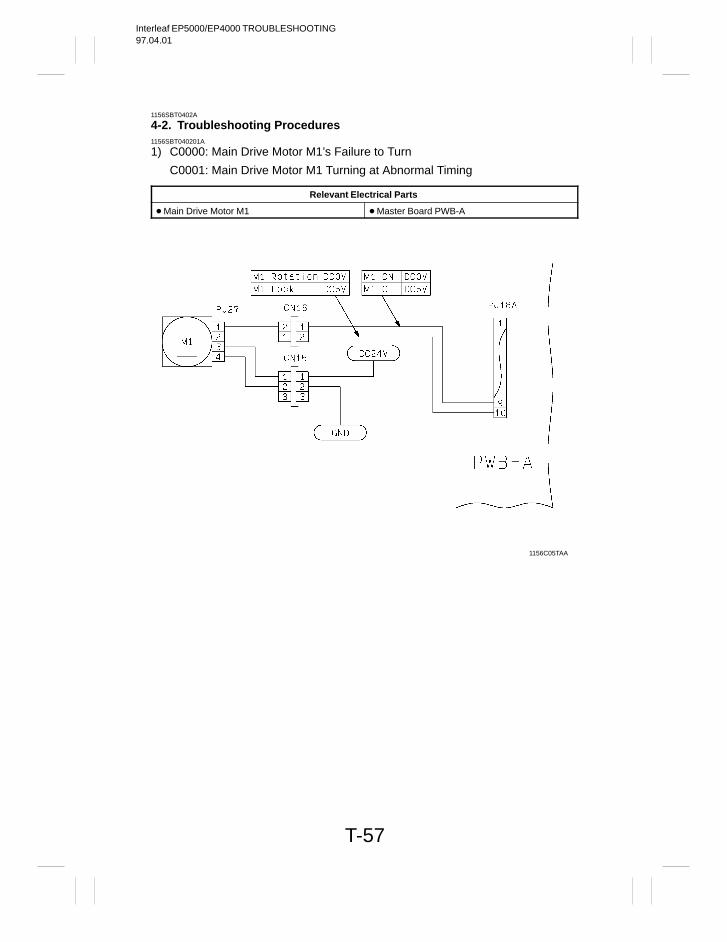
Interleaf EP5000/EP4000 TROUBLESHOOTING97.04.01
T-57
1156SBT0402A
4-2. Troubleshooting Procedures1156SBT040201A
1) C0000: Main Drive Motor M1’s Failure to Turn
C0001: Main Drive Motor M1 Turning at Abnormal Timing
Relevant Electrical Parts
Main Drive Motor M1 Master Board PWB-A
1156C05TAA
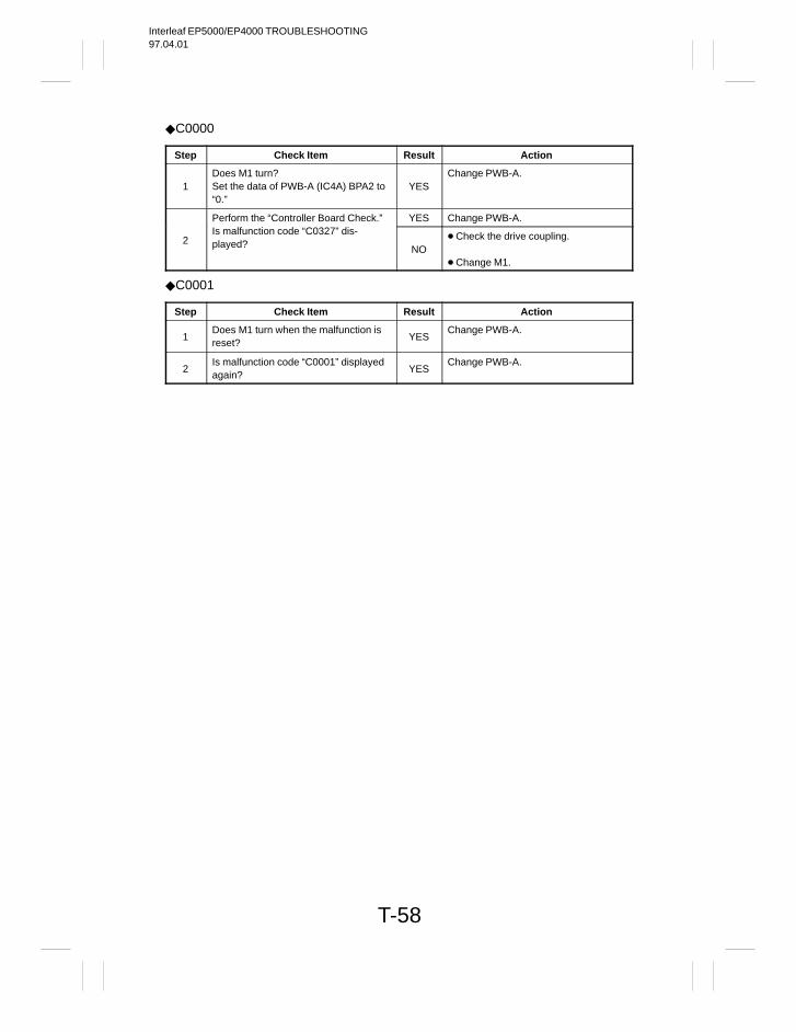
Interleaf EP5000/EP4000 TROUBLESHOOTING97.04.01
T-58
C0000
Step Check Item Result Action
1Does M1 turn?Set the data of PWB-A (IC4A) BPA2 to“0.”
YESChange PWB-A.
Perform the “Controller Board Check.” YES Change PWB-A.
2Is malfunction code “C0327” dis-played? NO
Check the drive coupling.
Change M1.
C0001
Step Check Item Result Action
1Does M1 turn when the malfunction isreset?
YESChange PWB-A.
2Is malfunction code “C0001” displayedagain?
YESChange PWB-A.
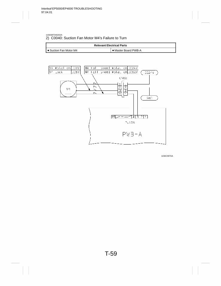
Interleaf EP5000/EP4000 TROUBLESHOOTING97.04.01
T-59
1156SBT040202A
2) C0040: Suction Fan Motor M4’s Failure to Turn
Relevant Electrical Parts
Suction Fan Motor M4 Master Board PWB-A
1156C06TAA
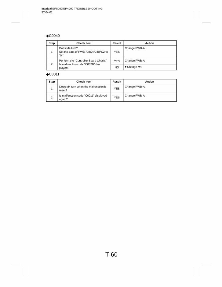
Interleaf EP5000/EP4000 TROUBLESHOOTING97.04.01
T-60
C0040
Step Check Item Result Action
1Does M4 turn?Set the data of PWB-A (IC4A) BPC2 to“0.”
YESChange PWB-A.
Perform the “Controller Board Check.” YES Change PWB-A.2 Is malfunction code “C032B” dis-
played? NO Change M4.
C0011
Step Check Item Result Action
1Does M4 turn when the malfunction isreset?
YESChange PWB-A.
2Is malfunction code “C0011” displayedagain?
YESChange PWB-A.

Interleaf EP5000/EP4000 TROUBLESHOOTING97.04.01
T-61
1156SBT040203A
3) C0046: Fusing Section Cooling Fan Motor M15’s Failure to Turn
C0047: Fusing Section Cooling Fan Motor M15 Turning at Abnormal Timing
Relevant Electrical Parts
Fusing Section Cooling Fan Motor M15 Master Board PWB-A
1156C07TAA
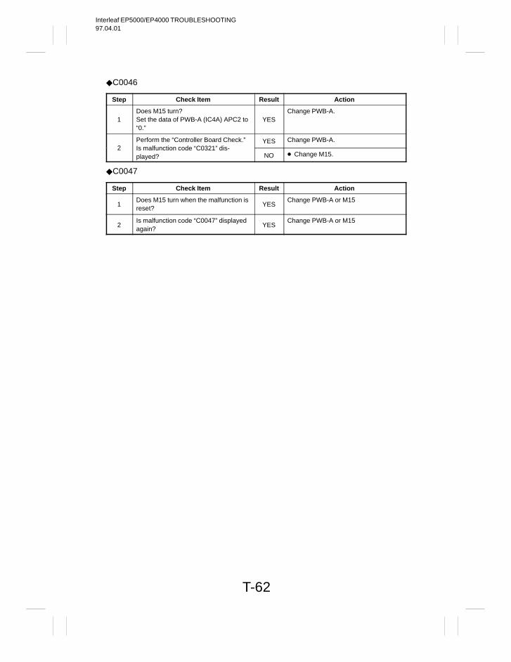
Interleaf EP5000/EP4000 TROUBLESHOOTING97.04.01
T-62
C0046
Step Check Item Result Action
1Does M15 turn?Set the data of PWB-A (IC4A) APC2 to“0.”
YESChange PWB-A.
Perform the “Controller Board Check.” YES Change PWB-A.2 Is malfunction code “C0321” dis-
played? NO Change M15.
C0047
Step Check Item Result Action
1Does M15 turn when the malfunction isreset?
YESChange PWB-A or M15
2Is malfunction code “C0047” displayedagain?
YESChange PWB-A or M15
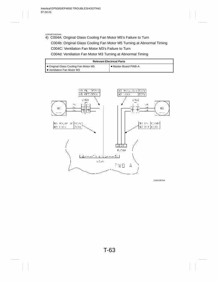
Interleaf EP5000/EP4000 TROUBLESHOOTING97.04.01
T-63
1156SBT040204A
4) C004A: Original Glass Cooling Fan Motor M5’s Failure to Turn
C004b: Original Glass Cooling Fan Motor M5 Turning at Abnormal Timing
C004C: Ventilation Fan Motor M3’s Failure to Turn
C004d: Ventilation Fan Motor M3 Turning at Abnormal Timing
Relevant Electrical Parts
Original Glass Cooling Fan Motor M5 Ventilation Fan Motor M3
Master Board PWB-A
1156C08TAA
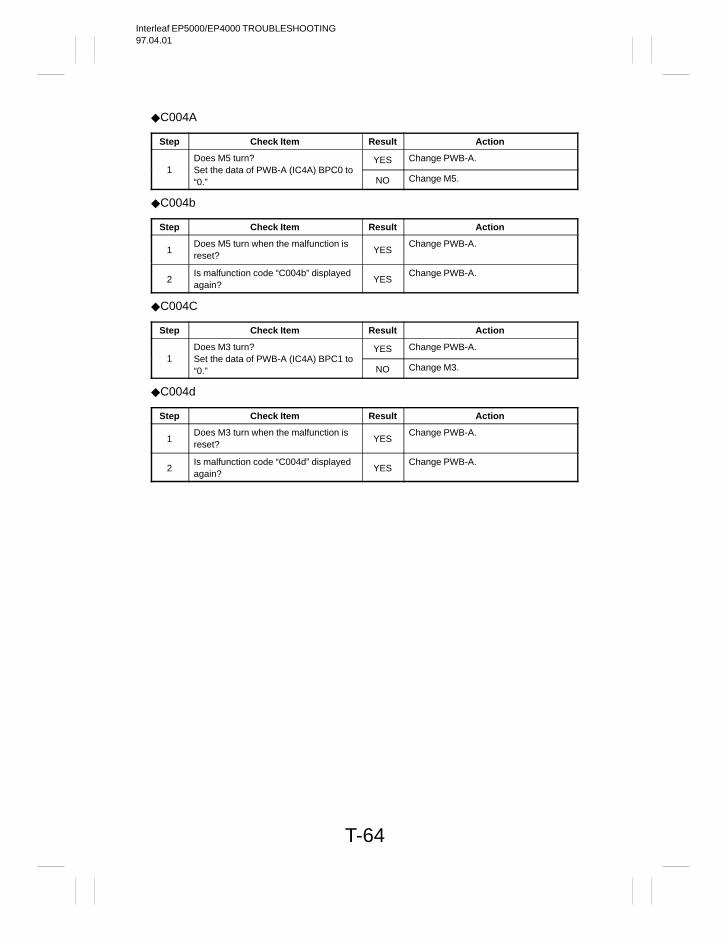
Interleaf EP5000/EP4000 TROUBLESHOOTING97.04.01
T-64
C004A
Step Check Item Result Action
Does M5 turn? YES Change PWB-A.1 Set the data of PWB-A (IC4A) BPC0 to
“0.” NO Change M5.
C004b
Step Check Item Result Action
1Does M5 turn when the malfunction isreset?
YESChange PWB-A.
2Is malfunction code “C004b” displayedagain?
YESChange PWB-A.
C004C
Step Check Item Result Action
Does M3 turn? YES Change PWB-A.1 Set the data of PWB-A (IC4A) BPC1 to
“0.” NO Change M3.
C004d
Step Check Item Result Action
1Does M3 turn when the malfunction isreset?
YESChange PWB-A.
2Is malfunction code “C004d” displayedagain?
YESChange PWB-A.
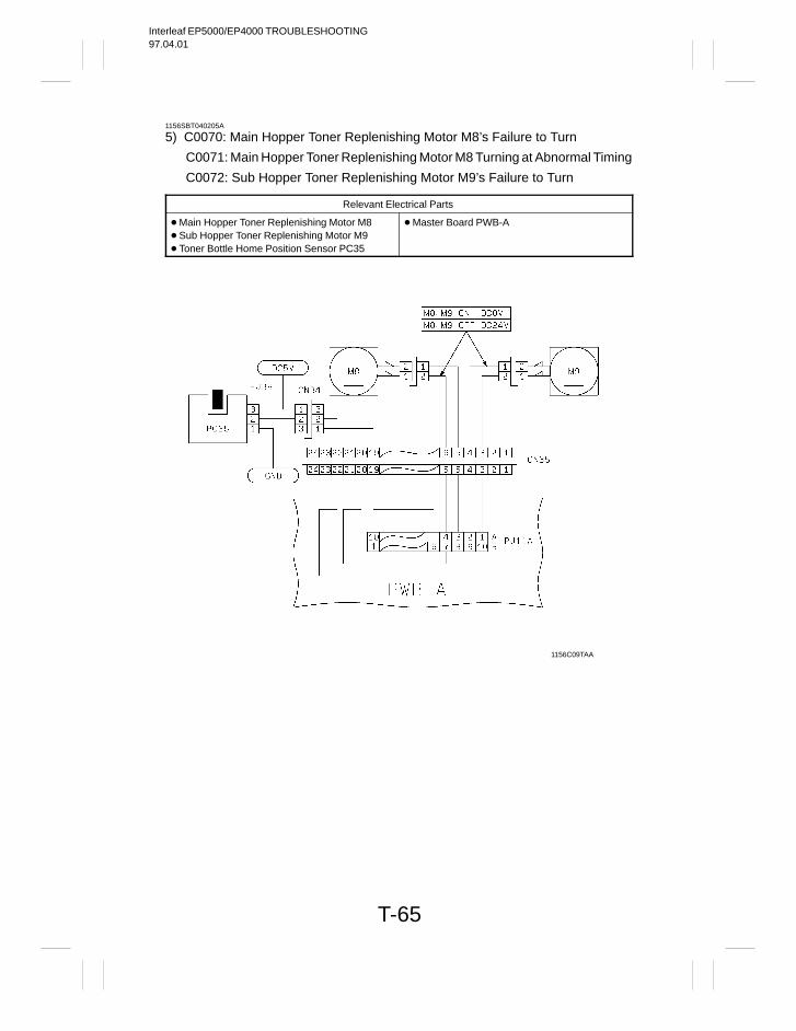
Interleaf EP5000/EP4000 TROUBLESHOOTING97.04.01
T-65
1156SBT040205A
5) C0070: Main Hopper Toner Replenishing Motor M8’s Failure to Turn
C0071: Main Hopper Toner Replenishing Motor M8 Turning at Abnormal Timing
C0072: Sub Hopper Toner Replenishing Motor M9’s Failure to Turn
Relevant Electrical Parts
Main Hopper Toner Replenishing Motor M8 Sub Hopper Toner Replenishing Motor M9 Toner Bottle Home Position Sensor PC35
Master Board PWB-A
1156C09TAA
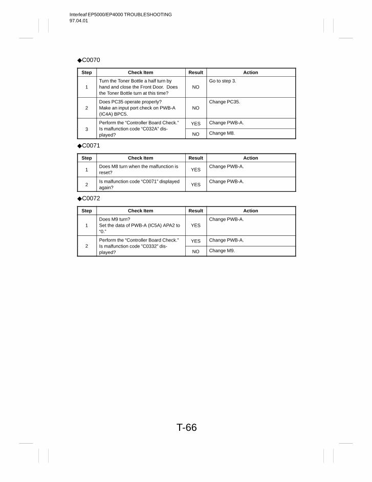
Interleaf EP5000/EP4000 TROUBLESHOOTING97.04.01
T-66
C0070
Step Check Item Result Action
1Turn the Toner Bottle a half turn byhand and close the Front Door. Doesthe Toner Bottle turn at this time?
NOGo to step 3.
2Does PC35 operate properly?Make an input port check on PWB-A(IC4A) BPC5.
NOChange PC35.
Perform the “Controller Board Check.” YES Change PWB-A.3 Is malfunction code “C032A” dis-
played? NO Change M8.
C0071
Step Check Item Result Action
1Does M8 turn when the malfunction isreset?
YESChange PWB-A.
2Is malfunction code “C0071” displayedagain?
YESChange PWB-A.
C0072
Step Check Item Result Action
1Does M9 turn?Set the data of PWB-A (IC5A) APA2 to“0.”
YESChange PWB-A.
Perform the “Controller Board Check.” YES Change PWB-A.2 Is malfunction code ”C0332” dis-
played? NO Change M9.
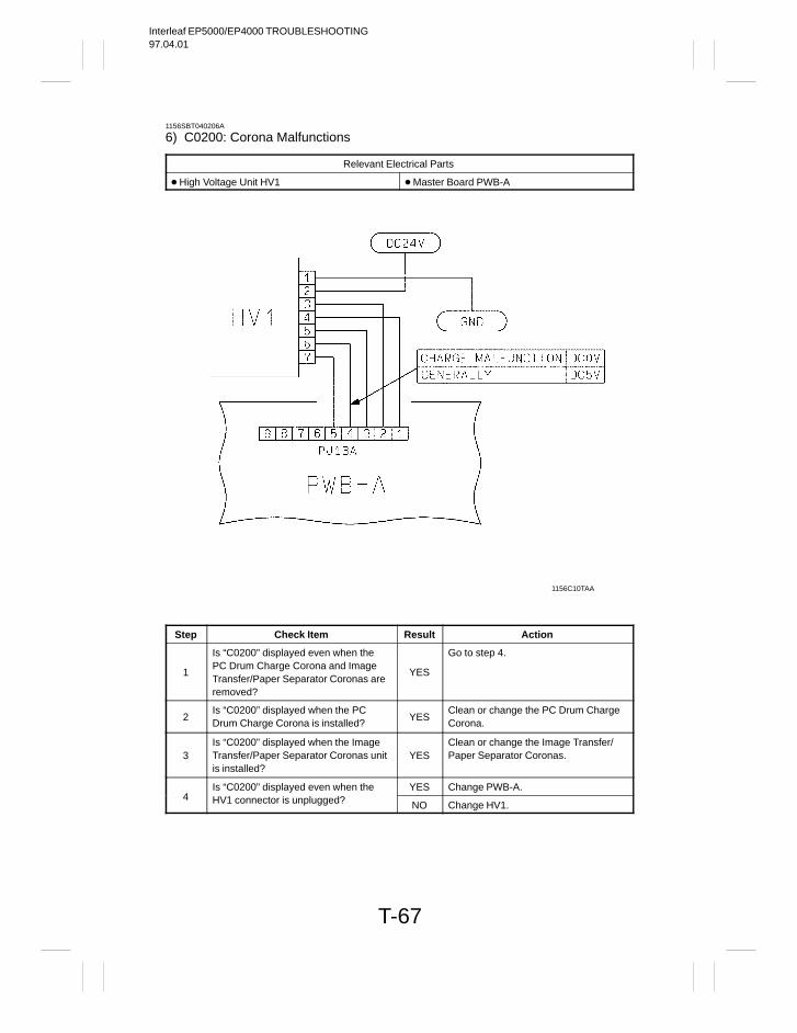
Interleaf EP5000/EP4000 TROUBLESHOOTING97.04.01
T-67
1156SBT040206A
6) C0200: Corona Malfunctions
Relevant Electrical Parts
High Voltage Unit HV1 Master Board PWB-A
1156C10TAA
Step Check Item Result Action
1
Is “C0200” displayed even when thePC Drum Charge Corona and ImageTransfer/Paper Separator Coronas areremoved?
YES
Go to step 4.
2Is “C0200” displayed when the PCDrum Charge Corona is installed?
YESClean or change the PC Drum ChargeCorona.
3Is “C0200” displayed when the ImageTransfer/Paper Separator Coronas unitis installed?
YESClean or change the Image Transfer/Paper Separator Coronas.
Is “C0200” displayed even when the YES Change PWB-A.4 HV1 connector is unplugged? NO Change HV1.
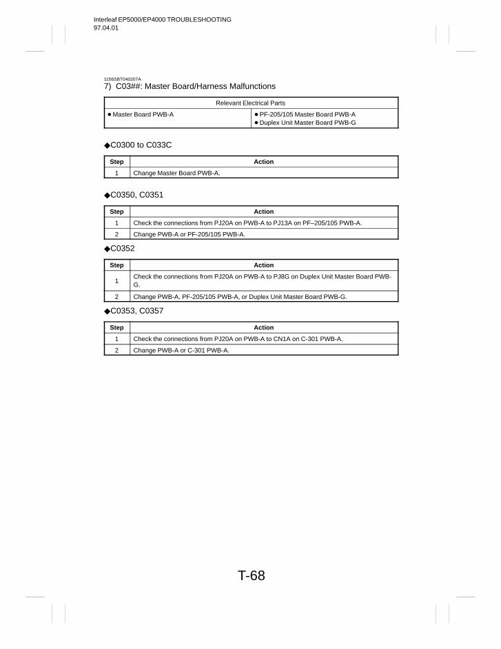
Interleaf EP5000/EP4000 TROUBLESHOOTING97.04.01
T-68
1156SBT040207A
7) C03##: Master Board/Harness Malfunctions
Relevant Electrical Parts
Master Board PWB-A PF-205/105 Master Board PWB-A Duplex Unit Master Board PWB-G
C0300 to C033C
Step Action
1 Change Master Board PWB-A.
C0350, C0351
Step Action
1 Check the connections from PJ20A on PWB-A to PJ13A on PF–205/105 PWB-A.
2 Change PWB-A or PF-205/105 PWB-A.
C0352
Step Action
1Check the connections from PJ20A on PWB-A to PJ8G on Duplex Unit Master Board PWB-G.
2 Change PWB-A, PF-205/105 PWB-A, or Duplex Unit Master Board PWB-G.
C0353, C0357
Step Action
1 Check the connections from PJ20A on PWB-A to CN1A on C-301 PWB-A.
2 Change PWB-A or C-301 PWB-A.
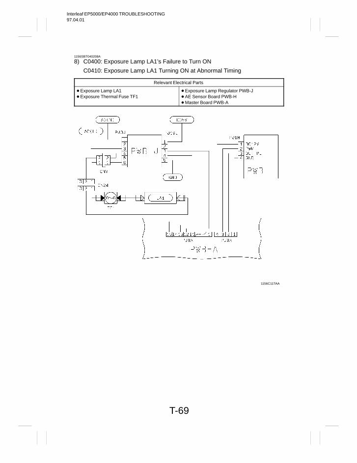
Interleaf EP5000/EP4000 TROUBLESHOOTING97.04.01
T-69
1156SBT040208A
8) C0400: Exposure Lamp LA1’s Failure to Turn ON
C0410: Exposure Lamp LA1 Turning ON at Abnormal Timing
Relevant Electrical Parts
Exposure Lamp LA1 Exposure Thermal Fuse TF1
Exposure Lamp Regulator PWB-J AE Sensor Board PWB-H Master Board PWB-A
1156C11TAA
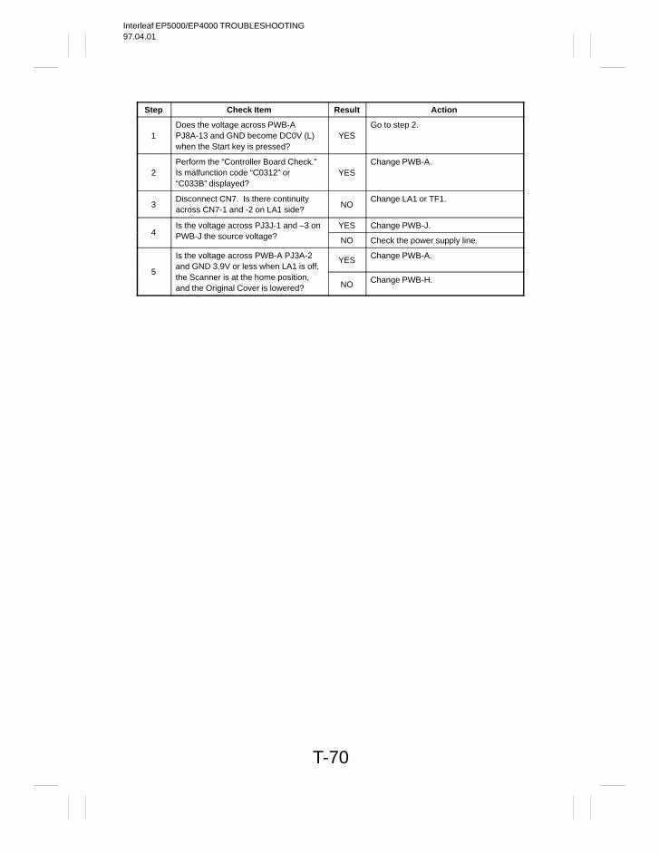
Interleaf EP5000/EP4000 TROUBLESHOOTING97.04.01
T-70
Step Check Item Result Action
1Does the voltage across PWB-APJ8A-13 and GND become DC0V (L)when the Start key is pressed?
YESGo to step 2.
2Perform the “Controller Board Check.”Is malfunction code “C0312” or“C033B” displayed?
YESChange PWB-A.
3Disconnect CN7. Is there continuityacross CN7-1 and -2 on LA1 side?
NOChange LA1 or TF1.
Is the voltage across PJ3J-1 and –3 on YES Change PWB-J.4 PWB-J the source voltage? NO Check the power supply line.
Is the voltage across PWB-A PJ3A-2and GND 3.9V or less when LA1 is off,
YES Change PWB-A.
5the Scanner is at the home position,and the Original Cover is lowered? NO Change PWB-H.
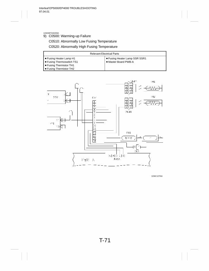
Interleaf EP5000/EP4000 TROUBLESHOOTING97.04.01
T-71
1156SBT040209A
9) C0500: Warming-up Failure
C0510: Abnormally Low Fusing Temperature
C0520: Abnormally High Fusing Temperature
Relevant Electrical Parts
Fusing Heater Lamp H1 Fusing Thermoswitch TS1 Fusing Thermistor TH1 Fusing Thermistor TH2
Fusing Heater Lamp SSR SSR1 Master Board PWB-A
1156C12TAA
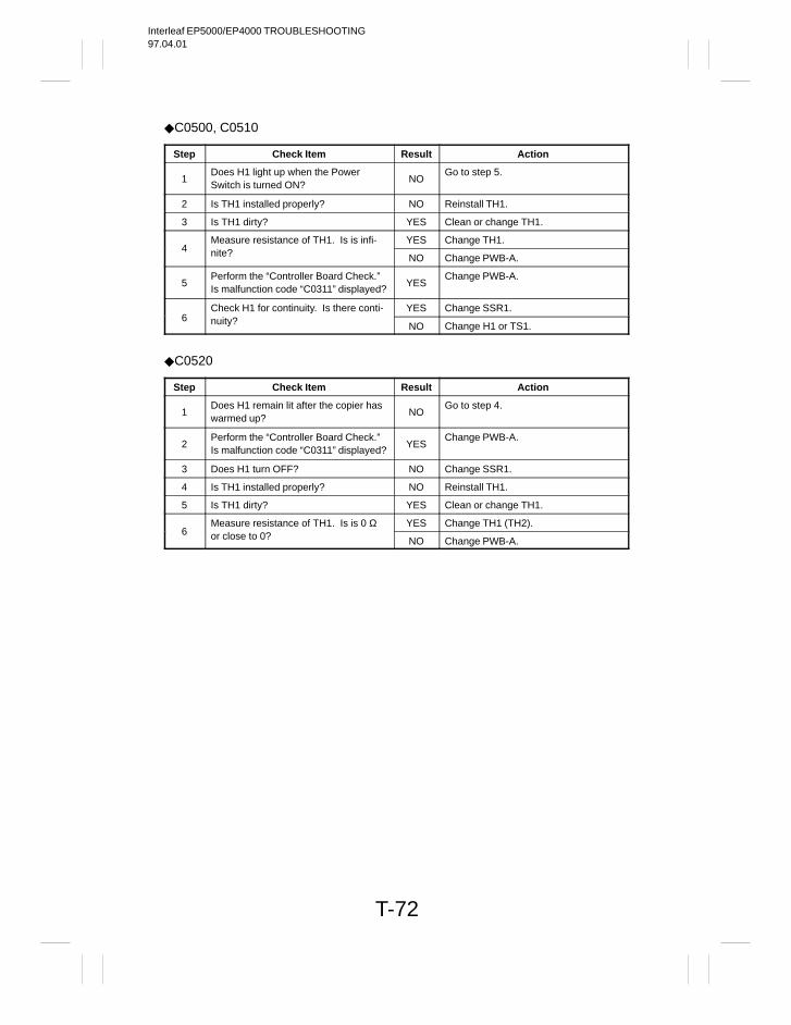
Interleaf EP5000/EP4000 TROUBLESHOOTING97.04.01
T-72
C0500, C0510
Step Check Item Result Action
1Does H1 light up when the PowerSwitch is turned ON?
NOGo to step 5.
2 Is TH1 installed properly? NO Reinstall TH1.
3 Is TH1 dirty? YES Clean or change TH1.
Measure resistance of TH1. Is is infi- YES Change TH1.4 nite? NO Change PWB-A.
5Perform the “Controller Board Check.”Is malfunction code “C0311” displayed?
YESChange PWB-A.
Check H1 for continuity. Is there conti- YES Change SSR1.6 nuity? NO Change H1 or TS1.
C0520
Step Check Item Result Action
1Does H1 remain lit after the copier haswarmed up?
NOGo to step 4.
2Perform the “Controller Board Check.”Is malfunction code “C0311” displayed?
YESChange PWB-A.
3 Does H1 turn OFF? NO Change SSR1.
4 Is TH1 installed properly? NO Reinstall TH1.
5 Is TH1 dirty? YES Clean or change TH1.
Measure resistance of TH1. Is is 0 Ω YES Change TH1 (TH2).6 or close to 0? NO Change PWB-A.
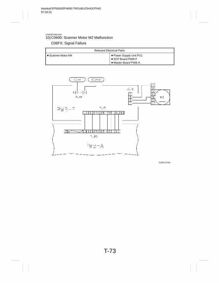
Interleaf EP5000/EP4000 TROUBLESHOOTING97.04.01
T-73
1156SBT040210A
10)C0600: Scanner Motor M2 Malfunction
C06FX: Signal Failure
Relevant Electrical Parts
Scanner Motor M4 Power Supply Unit PU1 SCP Board PWB-F Master Board PWB-A
1156C13TAA
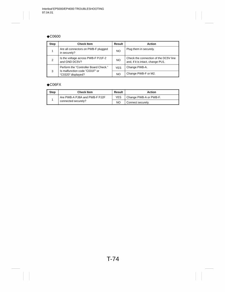
Interleaf EP5000/EP4000 TROUBLESHOOTING97.04.01
T-74
C0600
Step Check Item Result Action
1Are all connectors on PWB-F pluggedin securely?
NOPlug them in securely.
2Is the voltage across PWB-F PJ1F-2and GND DC5V?
NOCheck the connection of the DC5V lineand, if it is intact, change PU1.
Perform the “Controller Board Check.” YES Change PWB-A.3 Is malfunction code ”C031F” or
“C0320” displayed? NO Change PWB-F or M2.
C06FX
Step Check Item Result Action
Are PWB-A PJ8A and PWB-F PJ2F YES Change PWB-A or PWB-F.1 connected securely? NO Connect securely.
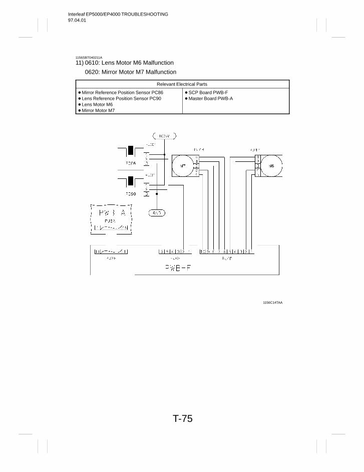
Interleaf EP5000/EP4000 TROUBLESHOOTING97.04.01
T-75
1156SBT040211A
11) 0610: Lens Motor M6 Malfunction
0620: Mirror Motor M7 Malfunction
Relevant Electrical Parts
Mirror Reference Position Sensor PC86 Lens Reference Position Sensor PC90 Lens Motor M6 Mirror Motor M7
SCP Board PWB-F Master Board PWB-A
1156C14TAA
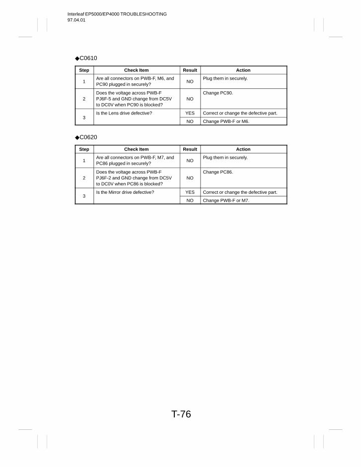
Interleaf EP5000/EP4000 TROUBLESHOOTING97.04.01
T-76
C0610
Step Check Item Result Action
1Are all connectors on PWB-F, M6, andPC90 plugged in securely?
NOPlug them in securely.
2Does the voltage across PWB-FPJ6F-5 and GND change from DC5Vto DC0V when PC90 is blocked?
NOChange PC90.
Is the Lens drive defective? YES Correct or change the defective part.3
NO Change PWB-F or M6.
C0620
Step Check Item Result Action
1Are all connectors on PWB-F, M7, andPC86 plugged in securely?
NOPlug them in securely.
2Does the voltage across PWB-FPJ6F-2 and GND change from DC5Vto DC0V when PC86 is blocked?
NOChange PC86.
Is the Mirror drive defective? YES Correct or change the defective part.3
NO Change PWB-F or M7.
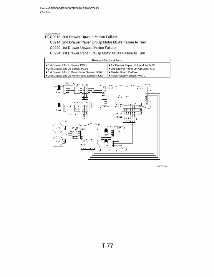
Interleaf EP5000/EP4000 TROUBLESHOOTING97.04.01
T-77
1156SBT040212A
12)C0910: 2nd Drawer Upward Motion Failure
C0914: 2nd Drawer Paper Lift-Up Motor M14’s Failure to Turn
C0920: 1st Drawer Upward Motion Failure
C0924: 1st Drawer Paper Lift-Up Motor M13’s Failure to Turn
Relevant Electrical Parts
1st Drawer Lift-Up Sensor PC65 2nd Drawer Lift-Up Sensor PC66 1st Drawer Lift-Up Motor Pulse Sensor PC67 2nd Drawer Lift-Up Motor Pulse Sensor PC68
1st Drawer Paper Lift-Up Motor M13 2nd Drawer Paper Lift-Up Motor M14 Master Board PWB-A Power Supply Board PWB-C
1156C15TAA
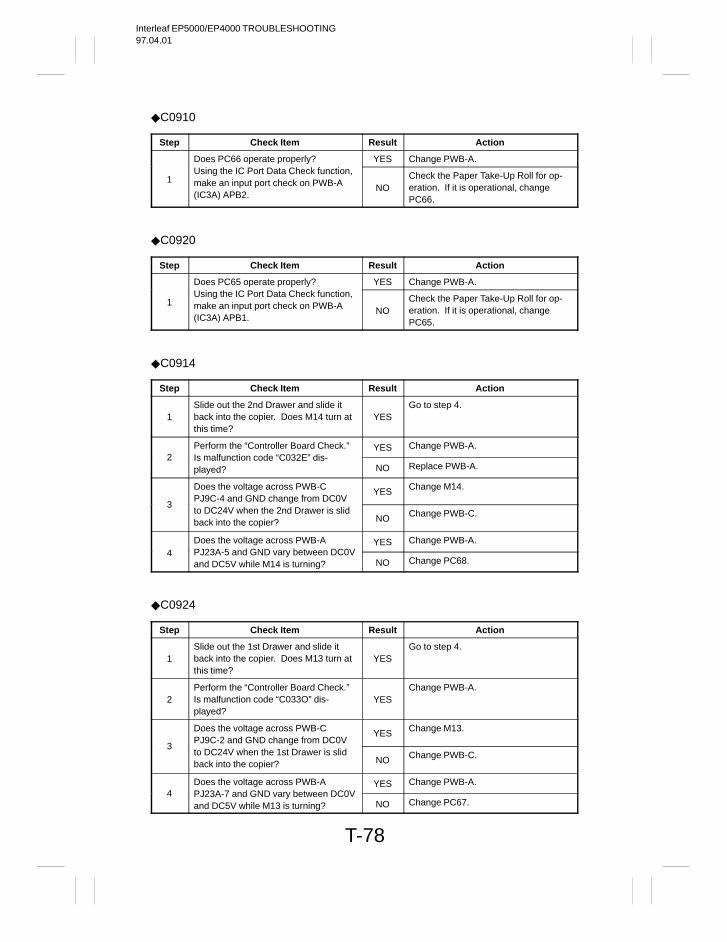
Interleaf EP5000/EP4000 TROUBLESHOOTING97.04.01
T-78
C0910
Step Check Item Result Action
Does PC66 operate properly? YES Change PWB-A.
1Using the IC Port Data Check function,make an input port check on PWB-A(IC3A) APB2.
NOCheck the Paper Take-Up Roll for op-eration. If it is operational, changePC66.
C0920
Step Check Item Result Action
Does PC65 operate properly? YES Change PWB-A.
1Using the IC Port Data Check function,make an input port check on PWB-A(IC3A) APB1.
NOCheck the Paper Take-Up Roll for op-eration. If it is operational, changePC65.
C0914
Step Check Item Result Action
1Slide out the 2nd Drawer and slide itback into the copier. Does M14 turn atthis time?
YESGo to step 4.
Perform the “Controller Board Check.” YES Change PWB-A.2 Is malfunction code “C032E” dis-
played? NO Replace PWB-A.
Does the voltage across PWB-CPJ9C-4 and GND change from DC0V
YES Change M14.
3to DC24V when the 2nd Drawer is slidback into the copier? NO Change PWB-C.
Does the voltage across PWB-A YES Change PWB-A.4 PJ23A-5 and GND vary between DC0V
and DC5V while M14 is turning? NO Change PC68.
C0924
Step Check Item Result Action
1Slide out the 1st Drawer and slide itback into the copier. Does M13 turn atthis time?
YESGo to step 4.
2Perform the “Controller Board Check.”Is malfunction code “C033O” dis-played?
YESChange PWB-A.
Does the voltage across PWB-CPJ9C-2 and GND change from DC0V
YES Change M13.
3to DC24V when the 1st Drawer is slidback into the copier? NO Change PWB-C.
Does the voltage across PWB-A YES Change PWB-A.4 PJ23A-7 and GND vary between DC0V
and DC5V while M13 is turning? NO Change PC67.
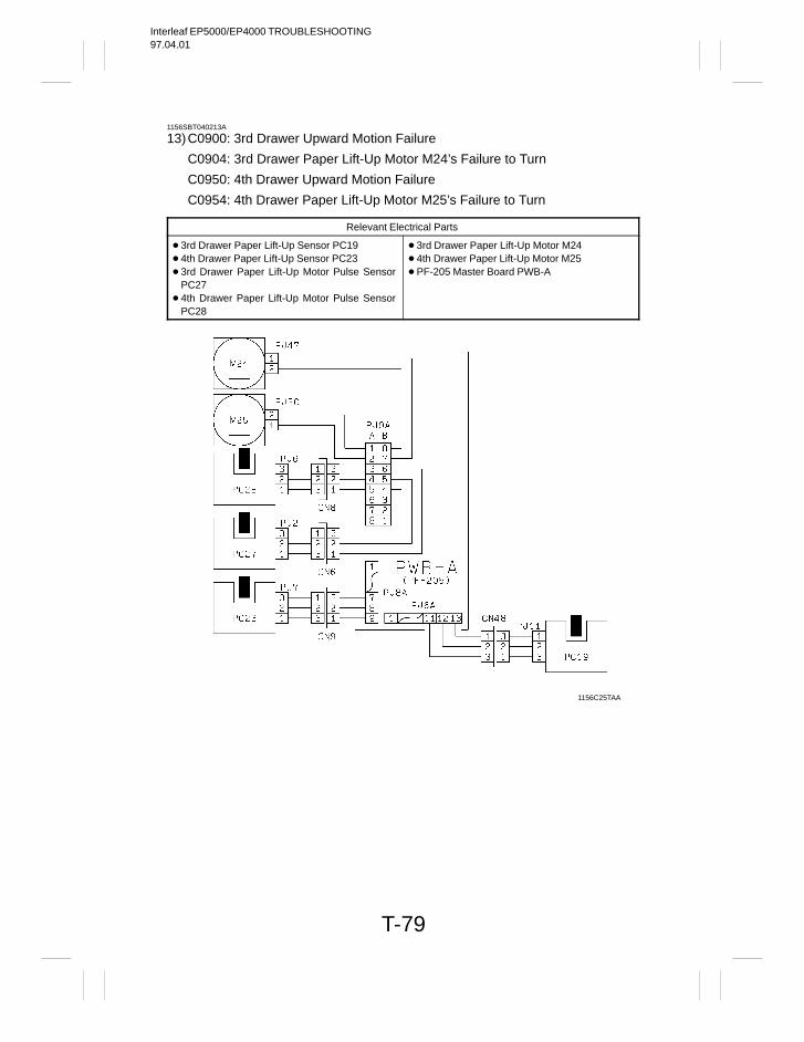
Interleaf EP5000/EP4000 TROUBLESHOOTING97.04.01
T-79
1156SBT040213A
13)C0900: 3rd Drawer Upward Motion Failure
C0904: 3rd Drawer Paper Lift-Up Motor M24’s Failure to Turn
C0950: 4th Drawer Upward Motion Failure
C0954: 4th Drawer Paper Lift-Up Motor M25’s Failure to Turn
Relevant Electrical Parts
3rd Drawer Paper Lift-Up Sensor PC19 4th Drawer Paper Lift-Up Sensor PC23 3rd Drawer Paper Lift-Up Motor Pulse Sensor
PC27 4th Drawer Paper Lift-Up Motor Pulse Sensor
PC28
3rd Drawer Paper Lift-Up Motor M24 4th Drawer Paper Lift-Up Motor M25 PF-205 Master Board PWB-A
1156C25TAA
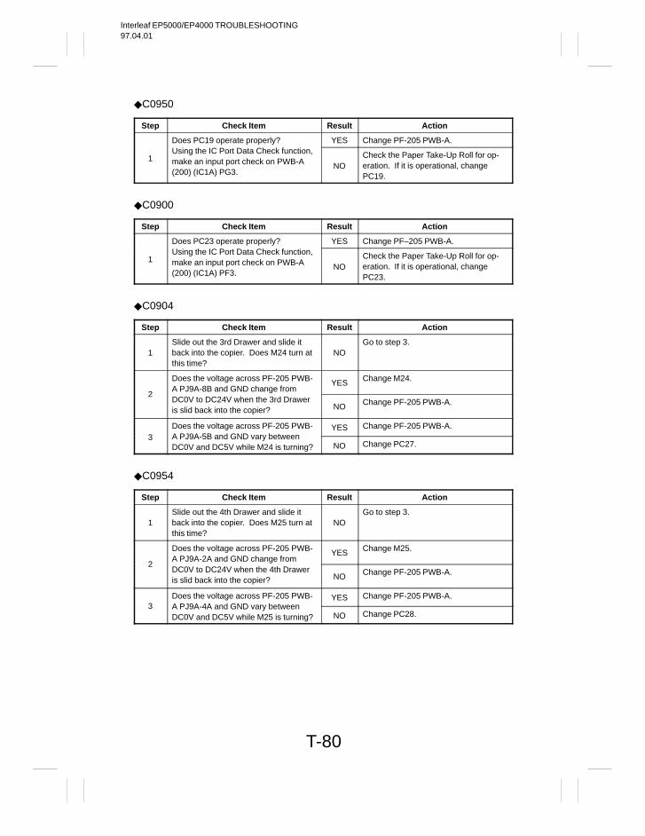
Interleaf EP5000/EP4000 TROUBLESHOOTING97.04.01
T-80
C0950
Step Check Item Result Action
Does PC19 operate properly? YES Change PF-205 PWB-A.
1Using the IC Port Data Check function,make an input port check on PWB-A(200) (IC1A) PG3.
NOCheck the Paper Take-Up Roll for op-eration. If it is operational, changePC19.
C0900
Step Check Item Result Action
Does PC23 operate properly? YES Change PF–205 PWB-A.
1Using the IC Port Data Check function,make an input port check on PWB-A(200) (IC1A) PF3.
NOCheck the Paper Take-Up Roll for op-eration. If it is operational, changePC23.
C0904
Step Check Item Result Action
1Slide out the 3rd Drawer and slide itback into the copier. Does M24 turn atthis time?
NOGo to step 3.
Does the voltage across PF-205 PWB-A PJ9A-8B and GND change from
YES Change M24.
2DC0V to DC24V when the 3rd Draweris slid back into the copier? NO Change PF-205 PWB-A.
Does the voltage across PF-205 PWB- YES Change PF-205 PWB-A.3 A PJ9A-5B and GND vary between
DC0V and DC5V while M24 is turning? NO Change PC27.
C0954
Step Check Item Result Action
1Slide out the 4th Drawer and slide itback into the copier. Does M25 turn atthis time?
NOGo to step 3.
Does the voltage across PF-205 PWB-A PJ9A-2A and GND change from
YES Change M25.
2DC0V to DC24V when the 4th Draweris slid back into the copier? NO Change PF-205 PWB-A.
Does the voltage across PF-205 PWB- YES Change PF-205 PWB-A.3 A PJ9A-4A and GND vary between
DC0V and DC5V while M25 is turning? NO Change PC28.
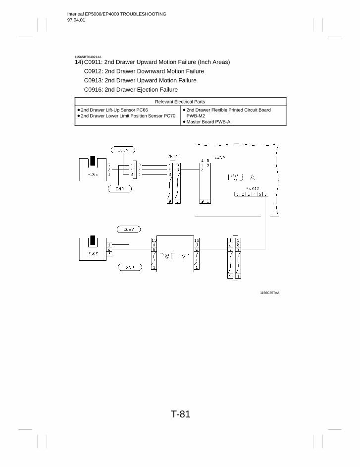
Interleaf EP5000/EP4000 TROUBLESHOOTING97.04.01
T-81
1156SBT040214A
14)C0911: 2nd Drawer Upward Motion Failure (Inch Areas)
C0912: 2nd Drawer Downward Motion Failure
C0913: 2nd Drawer Upward Motion Failure
C0916: 2nd Drawer Ejection Failure
Relevant Electrical Parts
2nd Drawer Lift-Up Sensor PC66 2nd Drawer Lower Limit Position Sensor PC70
2nd Drawer Flexible Printed Circuit Board PWB-M2
Master Board PWB-A
1156C35TAA

Interleaf EP5000/EP4000 TROUBLESHOOTING97.04.01
T-82
C0911
Step Check Item Result Action
Does PC66 operate properly?Using the IC Port Data Check function,
YES Replace PWB-A.
1 make an input port check on PWB-A(IC3A) APB2. NO Replace PC66 or PWB-M2.
C0912, C0913
Step Check Item Result Action
Does PC70 operate properly?Using the IC Port Data Check function,
YES Replace PWB-A.
1 make an input port check on PWB-A(IC3A) BPA3. NO Replace PC70 or PWB-M2.
C0916
Step Check Item Result Action
1Remove the Right Door, lift up the LockLever with a flat-blade screwdriver tounlock and slide out the 2nd Drawer.
–
2Is the Lock Release Spring installedproperly?
NOReinstall or change.
3Are the Lock Lever and Torsion Springinstalled properly?
NOReinstall or change.
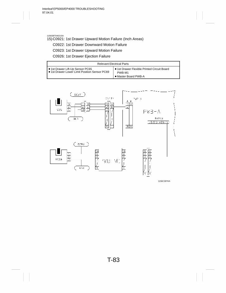
Interleaf EP5000/EP4000 TROUBLESHOOTING97.04.01
T-83
1156SBT040215A
15)C0921: 1st Drawer Upward Motion Failure (Inch Areas)
C0922: 1st Drawer Downward Motion Failure
C0923: 1st Drawer Upward Motion Failure
C0926: 1st Drawer Ejection Failure
Relevant Electrical Parts
1st Drawer Lift-Up Sensor PC65 1st Drawer Lower Limit Position Sensor PC69
1st Drawer Flexible Printed Circuit Board PWB-M1
Master Board PWB-A
1156C36TAA
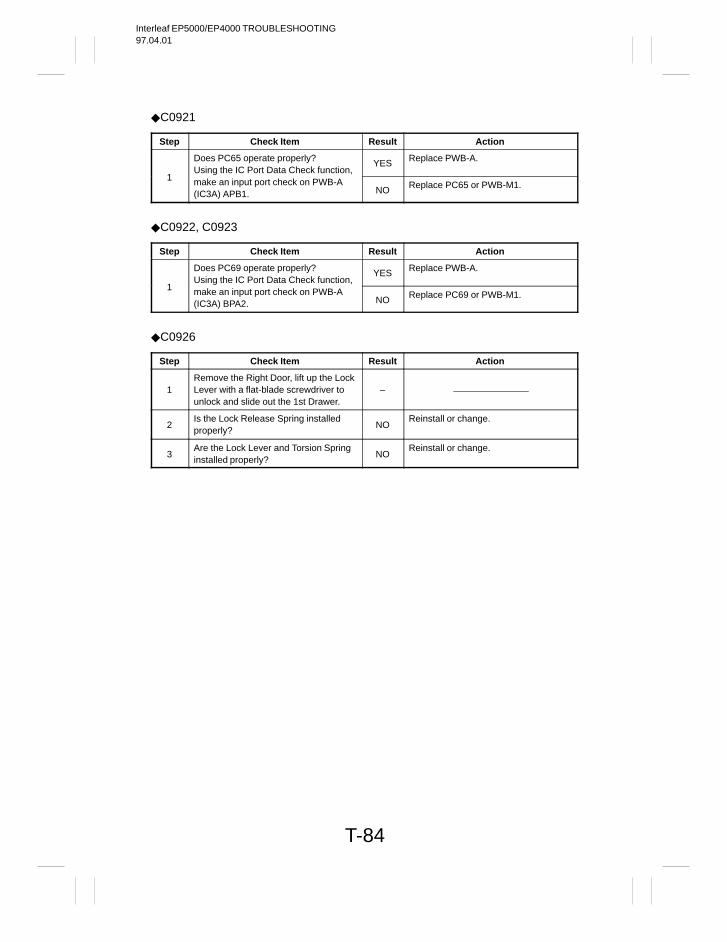
Interleaf EP5000/EP4000 TROUBLESHOOTING97.04.01
T-84
C0921
Step Check Item Result Action
Does PC65 operate properly?Using the IC Port Data Check function,
YES Replace PWB-A.
1 make an input port check on PWB-A(IC3A) APB1. NO Replace PC65 or PWB-M1.
C0922, C0923
Step Check Item Result Action
Does PC69 operate properly?Using the IC Port Data Check function,
YES Replace PWB-A.
1 make an input port check on PWB-A(IC3A) BPA2. NO Replace PC69 or PWB-M1.
C0926
Step Check Item Result Action
1Remove the Right Door, lift up the LockLever with a flat-blade screwdriver tounlock and slide out the 1st Drawer.
–
2Is the Lock Release Spring installedproperly?
NOReinstall or change.
3Are the Lock Lever and Torsion Springinstalled properly?
NOReinstall or change.
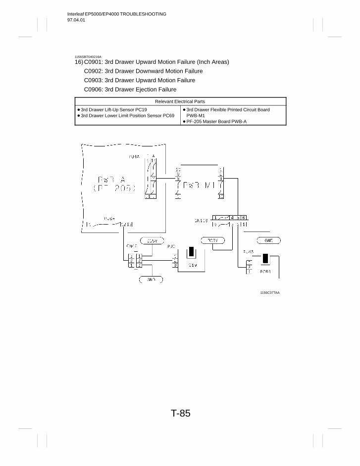
Interleaf EP5000/EP4000 TROUBLESHOOTING97.04.01
T-85
1156SBT040216A
16)C0901: 3rd Drawer Upward Motion Failure (Inch Areas)
C0902: 3rd Drawer Downward Motion Failure
C0903: 3rd Drawer Upward Motion Failure
C0906: 3rd Drawer Ejection Failure
Relevant Electrical Parts
3rd Drawer Lift-Up Sensor PC19 3rd Drawer Lower Limit Position Sensor PC69
3rd Drawer Flexible Printed Circuit Board PWB-M1
PF-205 Master Board PWB-A
1156C37TAA
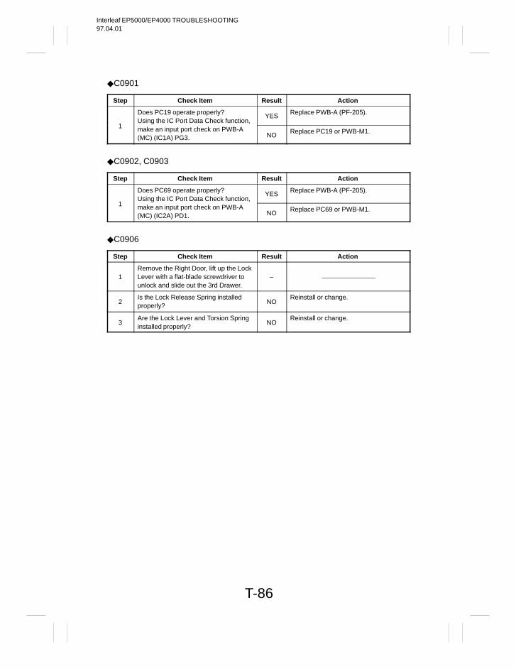
Interleaf EP5000/EP4000 TROUBLESHOOTING97.04.01
T-86
C0901
Step Check Item Result Action
Does PC19 operate properly?Using the IC Port Data Check function,
YES Replace PWB-A (PF-205).
1 make an input port check on PWB-A(MC) (IC1A) PG3. NO Replace PC19 or PWB-M1.
C0902, C0903
Step Check Item Result Action
Does PC69 operate properly?Using the IC Port Data Check function,
YES Replace PWB-A (PF-205).
1 make an input port check on PWB-A(MC) (IC2A) PD1. NO Replace PC69 or PWB-M1.
C0906
Step Check Item Result Action
1Remove the Right Door, lift up the LockLever with a flat-blade screwdriver tounlock and slide out the 3rd Drawer.
–
2Is the Lock Release Spring installedproperly?
NOReinstall or change.
3Are the Lock Lever and Torsion Springinstalled properly?
NOReinstall or change.
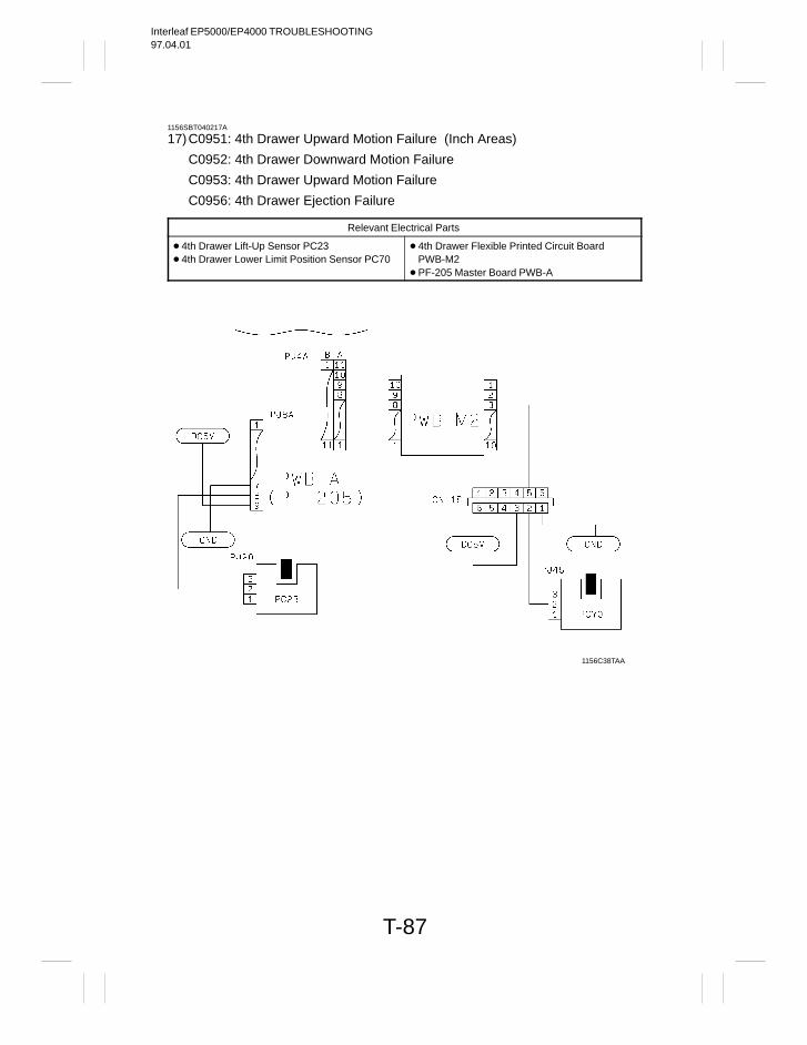
Interleaf EP5000/EP4000 TROUBLESHOOTING97.04.01
T-87
1156SBT040217A
17)C0951: 4th Drawer Upward Motion Failure (Inch Areas)
C0952: 4th Drawer Downward Motion Failure
C0953: 4th Drawer Upward Motion Failure
C0956: 4th Drawer Ejection Failure
Relevant Electrical Parts
4th Drawer Lift-Up Sensor PC23 4th Drawer Lower Limit Position Sensor PC70
4th Drawer Flexible Printed Circuit Board PWB-M2
PF-205 Master Board PWB-A
1156C38TAA
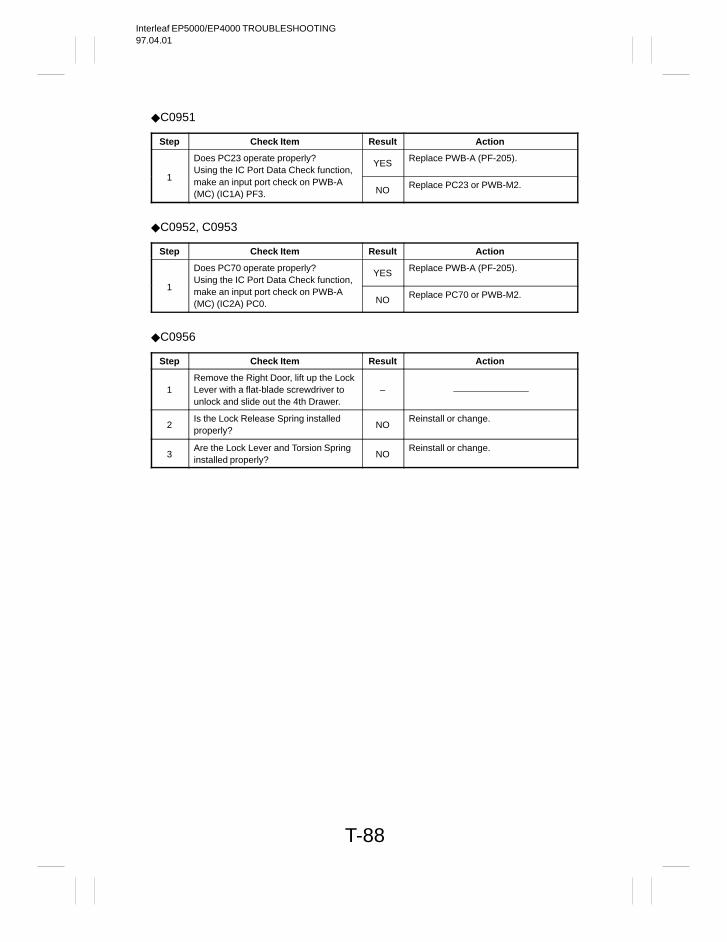
Interleaf EP5000/EP4000 TROUBLESHOOTING97.04.01
T-88
C0951
Step Check Item Result Action
Does PC23 operate properly?Using the IC Port Data Check function,
YES Replace PWB-A (PF-205).
1 make an input port check on PWB-A(MC) (IC1A) PF3. NO Replace PC23 or PWB-M2.
C0952, C0953
Step Check Item Result Action
Does PC70 operate properly?Using the IC Port Data Check function,
YES Replace PWB-A (PF-205).
1 make an input port check on PWB-A(MC) (IC2A) PC0. NO Replace PC70 or PWB-M2.
C0956
Step Check Item Result Action
1Remove the Right Door, lift up the LockLever with a flat-blade screwdriver tounlock and slide out the 4th Drawer.
–
2Is the Lock Release Spring installedproperly?
NOReinstall or change.
3Are the Lock Lever and Torsion Springinstalled properly?
NOReinstall or change.
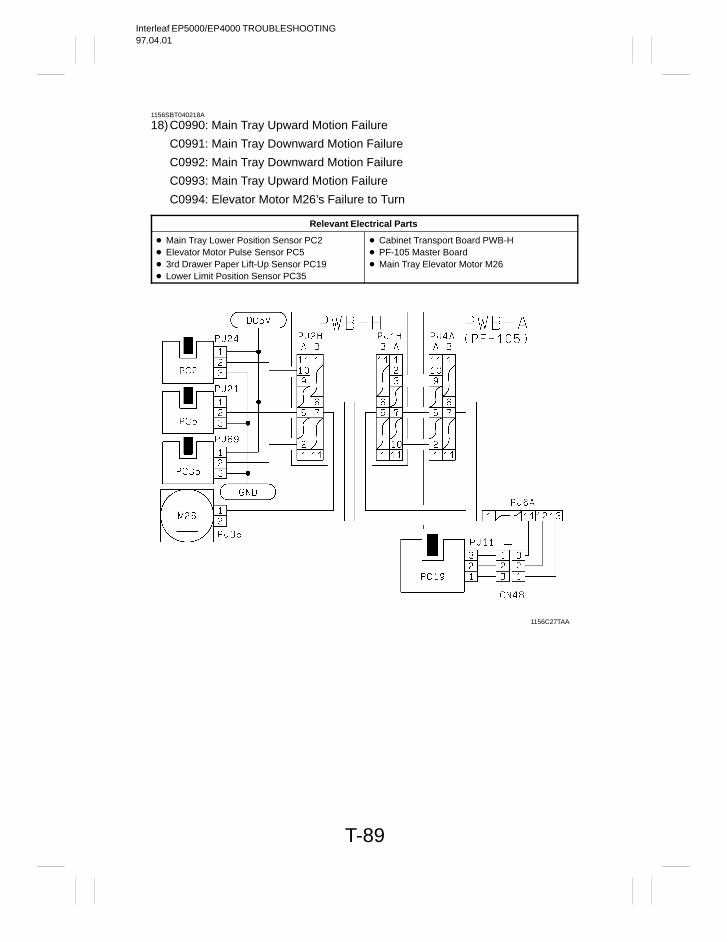
Interleaf EP5000/EP4000 TROUBLESHOOTING97.04.01
T-89
1156SBT040218A
18)C0990: Main Tray Upward Motion Failure
C0991: Main Tray Downward Motion Failure
C0992: Main Tray Downward Motion Failure
C0993: Main Tray Upward Motion Failure
C0994: Elevator Motor M26’s Failure to Turn
Relevant Electrical Parts
Main Tray Lower Position Sensor PC2 Elevator Motor Pulse Sensor PC5 3rd Drawer Paper Lift-Up Sensor PC19 Lower Limit Position Sensor PC35
Cabinet Transport Board PWB-H PF-105 Master Board Main Tray Elevator Motor M26
1156C27TAA
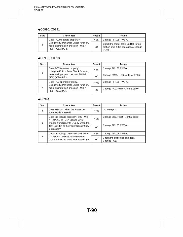
Interleaf EP5000/EP4000 TROUBLESHOOTING97.04.01
T-90
C0990, C0991
Step Check Item Result Action
Does PC19 operate properly? YES Change PF-105 PWB-A.
1Using the IC Port Data Check function,make an input port check on PWB-A(400) (IC1A) PG3.
NOCheck the Paper Take-Up Roll for op-eration and, if it is operational, changePC19.
C0992, C0993
Step Check Item Result Action
Does PC35 operate properly?Using the IC Port Data Check function,
YES Change PF-105 PWB-A.
1make an input port check on PWB-A(400) (IC2A) PB3. NO Change PWB-H, flat cable, or PC35.
Does PC2 operate properly?Using the IC Port Data Check function,
YES Change PF-105 PWB-A.
2 make an input port check on PWB-A(400) (IC2A) PC1. NO Change PC2, PWB-H, or flat cable.
C0994
Step Check Item Result Action
1Does M26 turn when the Paper De-scent key is pressed?
YESGo to step 3.
Does the voltage across PF-105 PWB-A PJ4A-6B or PJ4A-7B and GND YES
Change M26, PWB-H, or flat cable.
2 change from DC0V to DC24V when theTray is slid in or the Paper Descent keyis pressed?
NOChange PF-105 PWB-A.
Does the voltage across PF-105 PWB- YES Change PF-105 PWB-A.
3 A PJ4A-5A and GND vary betweenDC0V and DC5V while M26 is turning? NO
Check the pulse disk and gear.Change PC5.
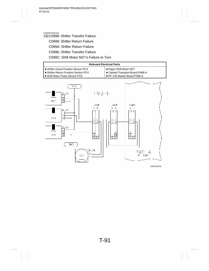
Interleaf EP5000/EP4000 TROUBLESHOOTING97.04.01
T-91
1156SBT040219A
19)C0998: Shifter Transfer Failure
C0999: Shifter Return Failure
C099A: Shifter Return Failure
C099b: Shifter Transfer Failure
C099C: Shift Motor M27’s Failure to Turn
Relevant Electrical Parts
Shifter Home Position Sensor PC3 Shifter Return Position Sensor PC4 Shift Motor Pulse Sensor PC6
Paper Shift Motor M27 Cabinet Transport Board PWB-H PF-105 Master Board PWB-A
1156C28TAA
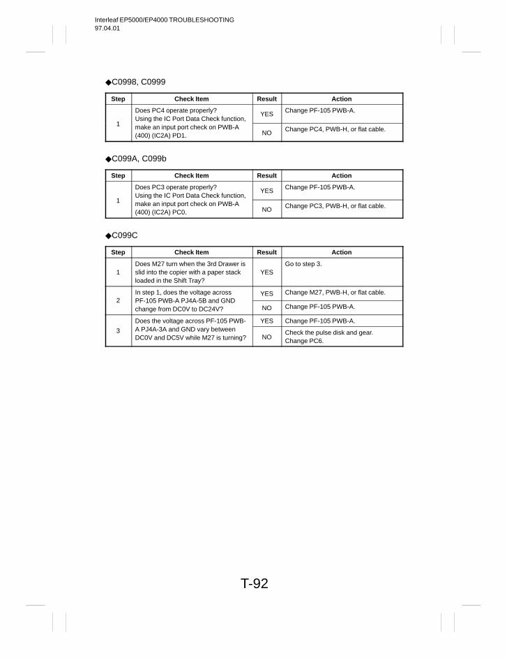
Interleaf EP5000/EP4000 TROUBLESHOOTING97.04.01
T-92
C0998, C0999
Step Check Item Result Action
Does PC4 operate properly?Using the IC Port Data Check function,
YES Change PF-105 PWB-A.
1 make an input port check on PWB-A(400) (IC2A) PD1. NO Change PC4, PWB-H, or flat cable.
C099A, C099b
Step Check Item Result Action
Does PC3 operate properly?Using the IC Port Data Check function,
YES Change PF-105 PWB-A.
1 make an input port check on PWB-A(400) (IC2A) PC0. NO Change PC3, PWB-H, or flat cable.
C099C
Step Check Item Result Action
1Does M27 turn when the 3rd Drawer isslid into the copier with a paper stackloaded in the Shift Tray?
YESGo to step 3.
In step 1, does the voltage across YES Change M27, PWB-H, or flat cable.2 PF-105 PWB-A PJ4A-5B and GND
change from DC0V to DC24V? NO Change PF-105 PWB-A.
Does the voltage across PF-105 PWB- YES Change PF-105 PWB-A.
3 A PJ4A-3A and GND vary betweenDC0V and DC5V while M27 is turning? NO
Check the pulse disk and gear.Change PC6.
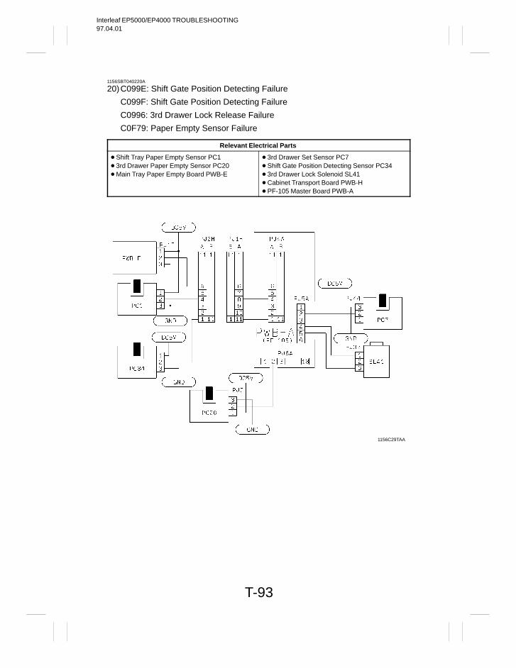
Interleaf EP5000/EP4000 TROUBLESHOOTING97.04.01
T-93
1156SBT040220A
20)C099E: Shift Gate Position Detecting Failure
C099F: Shift Gate Position Detecting Failure
C0996: 3rd Drawer Lock Release Failure
C0F79: Paper Empty Sensor Failure
Relevant Electrical Parts
Shift Tray Paper Empty Sensor PC1 3rd Drawer Paper Empty Sensor PC20 Main Tray Paper Empty Board PWB-E
3rd Drawer Set Sensor PC7 Shift Gate Position Detecting Sensor PC34 3rd Drawer Lock Solenoid SL41 Cabinet Transport Board PWB-H PF-105 Master Board PWB-A
1156C29TAA
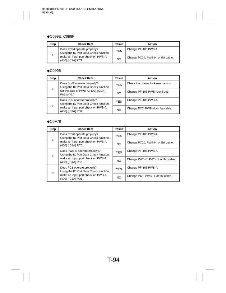
Interleaf EP5000/EP4000 TROUBLESHOOTING97.04.01
T-94
C099E, C099F
Step Check Item Result Action
Does PC34 operate properly?Using the IC Port Data Check function,
YES Change PF-105 PWB-A.
1 make an input port check on PWB-A(400) (IC1A) PC1. NO Change PC34, PWB-H, or flat cable.
C0996
Step Check Item Result Action
Does SL41 operate properly?Using the IC Port Data Check function,
YES Check the drawer lock mechanism.
1set the data of PWB-A (400) (IC2A)PA1 to ”0.” NO Change PF-105 PWB-A or SL41.
Does PC7 operate properly?Using the IC Port Data Check function,
YES Change PF-105 PWB-A.
2 make an input port check on PWB-A(400) (IC1A) PG2. NO Change PC7, PWB-H, or flat cable.
C0F79
Step Check Item Result Action
Does PC20 operate properly?Using the IC Port Data Check function,
YES Change PF-105 PWB-A.
1make an input port check on PWB-A(400) (IC1A) PC0. NO Change PC20, PWB-H, or flat cable.
Does PWB-E operate properly?Using the IC Port Data Check function,
YES Change PF-105 PWB-A.
2make an input port check on PWB-A(400) (IC1A) PF3. NO Change PWB-E, PWB-H, or flat cable.
Does PC1 operate properly?Using the IC Port Data Check function,
YES Change PF-105 PWB-A.
3make an input port check on PWB-A(400) (IC1A) PD1. NO Change PC1, PWB-H, or flat cable.
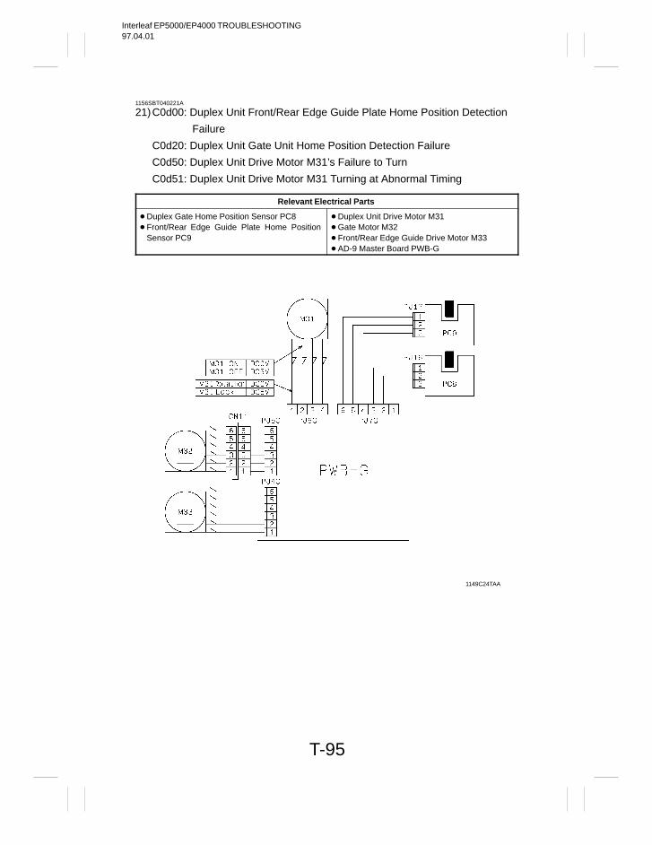
Interleaf EP5000/EP4000 TROUBLESHOOTING97.04.01
T-95
1156SBT040221A
21)C0d00: Duplex Unit Front/Rear Edge Guide Plate Home Position Detection
Failure
C0d20: Duplex Unit Gate Unit Home Position Detection Failure
C0d50: Duplex Unit Drive Motor M31’s Failure to Turn
C0d51: Duplex Unit Drive Motor M31 Turning at Abnormal Timing
Relevant Electrical Parts
Duplex Gate Home Position Sensor PC8 Front/Rear Edge Guide Plate Home Position
Sensor PC9
Duplex Unit Drive Motor M31 Gate Motor M32 Front/Rear Edge Guide Drive Motor M33 AD-9 Master Board PWB-G
1149C24TAA
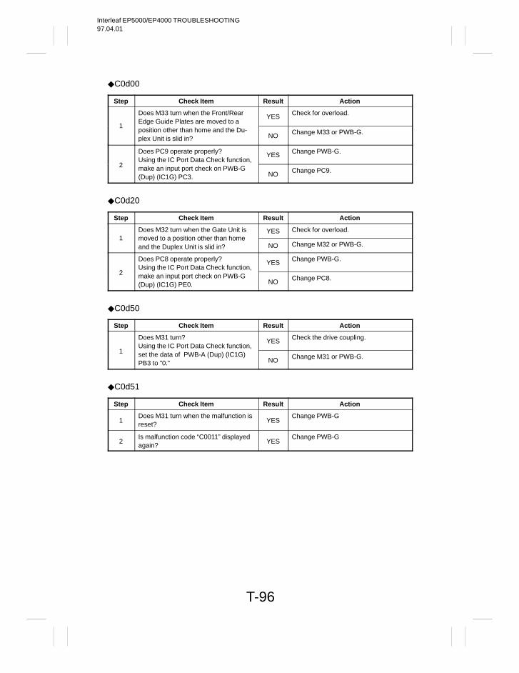
Interleaf EP5000/EP4000 TROUBLESHOOTING97.04.01
T-96
C0d00
Step Check Item Result Action
Does M33 turn when the Front/RearEdge Guide Plates are moved to a
YES Check for overload.
1position other than home and the Du-plex Unit is slid in? NO Change M33 or PWB-G.
Does PC9 operate properly?Using the IC Port Data Check function,
YES Change PWB-G.
2 make an input port check on PWB-G(Dup) (IC1G) PC3. NO Change PC9.
C0d20
Step Check Item Result Action
Does M32 turn when the Gate Unit is YES Check for overload.1 moved to a position other than home
and the Duplex Unit is slid in? NO Change M32 or PWB-G.
Does PC8 operate properly?Using the IC Port Data Check function,
YES Change PWB-G.
2 make an input port check on PWB-G(Dup) (IC1G) PE0. NO Change PC8.
C0d50
Step Check Item Result Action
Does M31 turn?Using the IC Port Data Check function,
YES Check the drive coupling.
1 set the data of PWB-A (Dup) (IC1G)PB3 to ”0.” NO Change M31 or PWB-G.
C0d51
Step Check Item Result Action
1Does M31 turn when the malfunction isreset?
YESChange PWB-G
2Is malfunction code “C0011” displayedagain?
YESChange PWB-G
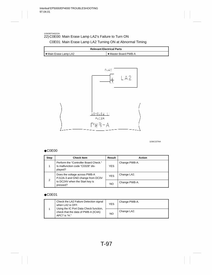
Interleaf EP5000/EP4000 TROUBLESHOOTING97.04.01
T-97
1156SBT040222A
22)C0E00: Main Erase Lamp LA2’s Failure to Turn ON
C0E01: Main Erase Lamp LA2 Turning ON at Abnormal Timing
Relevant Electrical Parts
Main Erase Lamp LA2 Master Board PWB-A
1156C22TAA
C0E00
Step Check Item Result Action
1Perform the “Controller Board Check.”Is malfunction code “C0328” dis-played?
YESChange PWB-A.
Does the voltage across PWB-APJ12A-3 and GND change from DC0V
YES Change LA2.
2 to DC24V when the Start key ispressed? NO Change PWB-A.
C0E01
Check the LA2 Failure Detection signalwhen LA2 is OFF. YES
Change PWB-A.
1 Using the IC Port Data Check function,check that the data of PWB-A (IC4A)APC7 is “H.”
NOChange LA2.
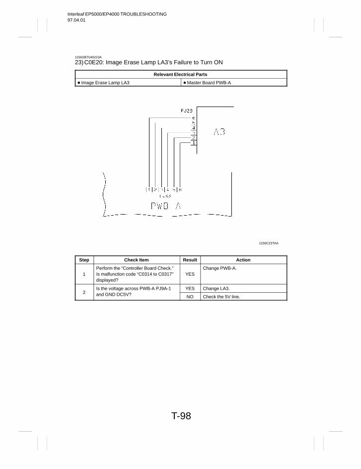
Interleaf EP5000/EP4000 TROUBLESHOOTING97.04.01
T-98
1156SBT040223A
23)C0E20: Image Erase Lamp LA3’s Failure to Turn ON
Relevant Electrical Parts
Image Erase Lamp LA3 Master Board PWB-A
1156C23TAA
Step Check Item Result Action
1Perform the “Controller Board Check.”Is malfunction code “C0314 to C0317”displayed?
YESChange PWB-A.
Is the voltage across PWB-A PJ9A-1 YES Change LA3.2 and GND DC5V? NO Check the 5V line.
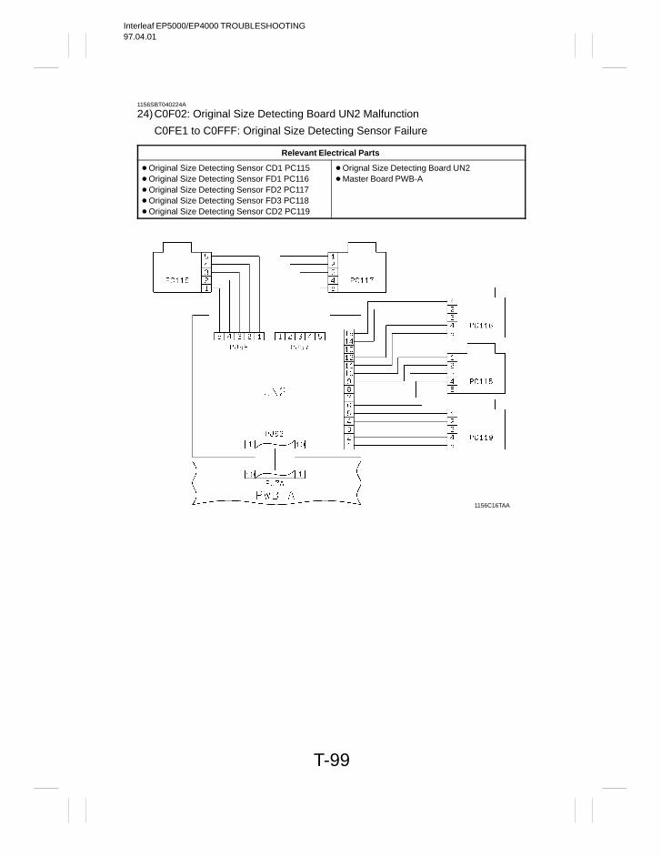
Interleaf EP5000/EP4000 TROUBLESHOOTING97.04.01
T-99
1156SBT040224A
24)C0F02: Original Size Detecting Board UN2 Malfunction
C0FE1 to C0FFF: Original Size Detecting Sensor Failure
Relevant Electrical Parts
Original Size Detecting Sensor CD1 PC115 Original Size Detecting Sensor FD1 PC116 Original Size Detecting Sensor FD2 PC117 Original Size Detecting Sensor FD3 PC118 Original Size Detecting Sensor CD2 PC119
Orignal Size Detecting Board UN2 Master Board PWB-A
1156C16TAA
Interleaf EP5000/EP4000 TROUBLESHOOTING97.04.01
T-100
C0F02
Step Check Item Result Action
1Are PJ62 on UN2 and PJ7A on PWB-Aplugged in securely?
NOPlug them in securely.
Does the voltage across PJ7A-6 on YES Change PWB-A.2 PWB-A and GND vary between DC0V
and DC5V? NO Change UN2.
C0FE1 to C0FFF
Step Check Item Result Action
1Are the jumper connectors pluggedcorrectly into J1 and J2 on UN2?
NOChange the jumper connector posi-tions.
2Is each Original Size Detecting Sensorinstalled in correct position?
NOReinstall.
3
Is the malfunction code displayed againafter the Original Size Detecting Sen-sor corresponding to the malfunctioncode has been changed?
YES
Change UN2 or PWB-A.
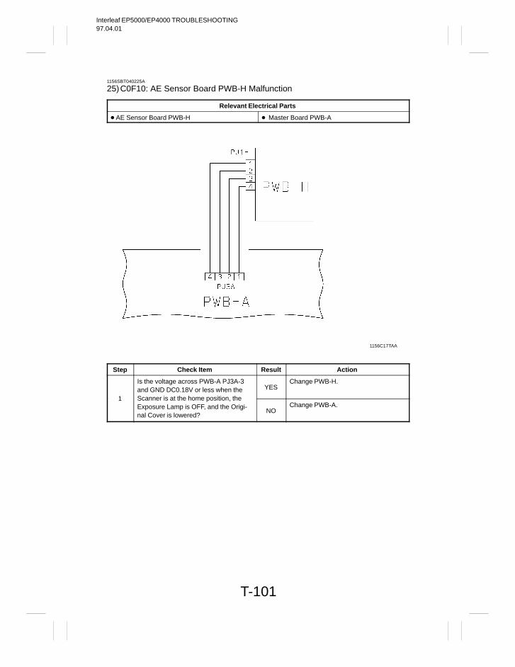
Interleaf EP5000/EP4000 TROUBLESHOOTING97.04.01
T-101
1156SBT040225A
25)C0F10: AE Sensor Board PWB-H Malfunction
Relevant Electrical Parts
AE Sensor Board PWB-H Master Board PWB-A
1156C17TAA
Step Check Item Result Action
Is the voltage across PWB-A PJ3A-3and GND DC0.18V or less when the YES
Change PWB-H.
1 Scanner is at the home position, theExposure Lamp is OFF, and the Origi-nal Cover is lowered?
NOChange PWB-A.
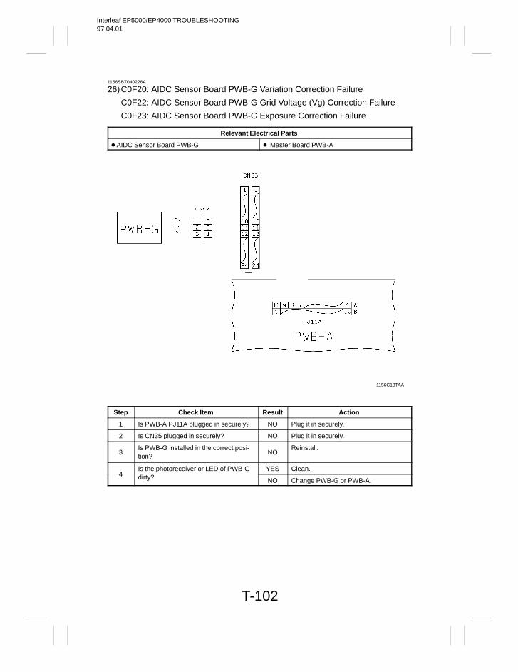
Interleaf EP5000/EP4000 TROUBLESHOOTING97.04.01
T-102
1156SBT040226A
26)C0F20: AIDC Sensor Board PWB-G Variation Correction Failure
C0F22: AIDC Sensor Board PWB-G Grid Voltage (Vg) Correction Failure
C0F23: AIDC Sensor Board PWB-G Exposure Correction Failure
Relevant Electrical Parts
AIDC Sensor Board PWB-G Master Board PWB-A
1156C18TAA
Step Check Item Result Action
1 Is PWB-A PJ11A plugged in securely? NO Plug it in securely.
2 Is CN35 plugged in securely? NO Plug it in securely.
3Is PWB-G installed in the correct posi-tion?
NOReinstall.
Is the photoreceiver or LED of PWB-G YES Clean.4 dirty? NO Change PWB-G or PWB-A.
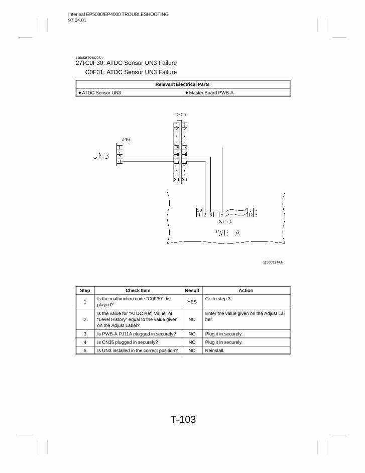
Interleaf EP5000/EP4000 TROUBLESHOOTING97.04.01
T-103
1156SBT040227A
27)C0F30: ATDC Sensor UN3 Failure
C0F31: ATDC Sensor UN3 Failure
Relevant Electrical Parts
ATDC Sensor UN3 Master Board PWB-A
1156C19TAA
Step Check Item Result Action
1Is the malfunction code “C0F30” dis-played?
YESGo to step 3.
2Is the value for “ATDC Ref. Value” of“Level History” equal to the value givenon the Adjust Label?
NOEnter the value given on the Adjust La-bel.
3 Is PWB-A PJ11A plugged in securely? NO Plug it in securely.
4 Is CN35 plugged in securely? NO Plug it in securely.
5 Is UN3 installed in the correct position? NO Reinstall.
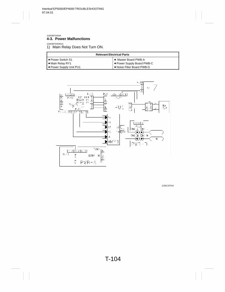
Interleaf EP5000/EP4000 TROUBLESHOOTING97.04.01
T-104
1156SBT0403A
4-3. Power Malfunctions1156SBT040301A
1) Main Relay Does Not Turn ON.
Relevant Electrical Parts
Power Switch S1 Main Relay RY1 Power Supply Unit PU1
Master Board PWB-A Power Supply Board PWB-C Noise Filter Board PWB-D
1156C20TAA
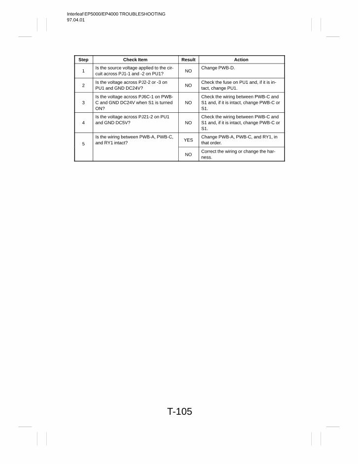
Interleaf EP5000/EP4000 TROUBLESHOOTING97.04.01
T-105
Step Check Item Result Action
1Is the source voltage applied to the cir-cuit across PJ1-1 and -2 on PU1?
NOChange PWB-D.
2Is the voltage across PJ2-2 or -3 onPU1 and GND DC24V?
NOCheck the fuse on PU1 and, if it is in-tact, change PU1.
3Is the voltage across PJ6C-1 on PWB-C and GND DC24V when S1 is turnedON?
NOCheck the wiring between PWB-C andS1 and, if it is intact, change PWB-C orS1.
4Is the voltage across PJ21-2 on PU1and GND DC5V? NO
Check the wiring between PWB-C andS1 and, if it is intact, change PWB-C orS1.
5
Is the wiring between PWB-A, PWB-C,and RY1 intact?
YESChange PWB-A, PWB-C, and RY1, inthat order.
NOCorrect the wiring or change the har-ness.
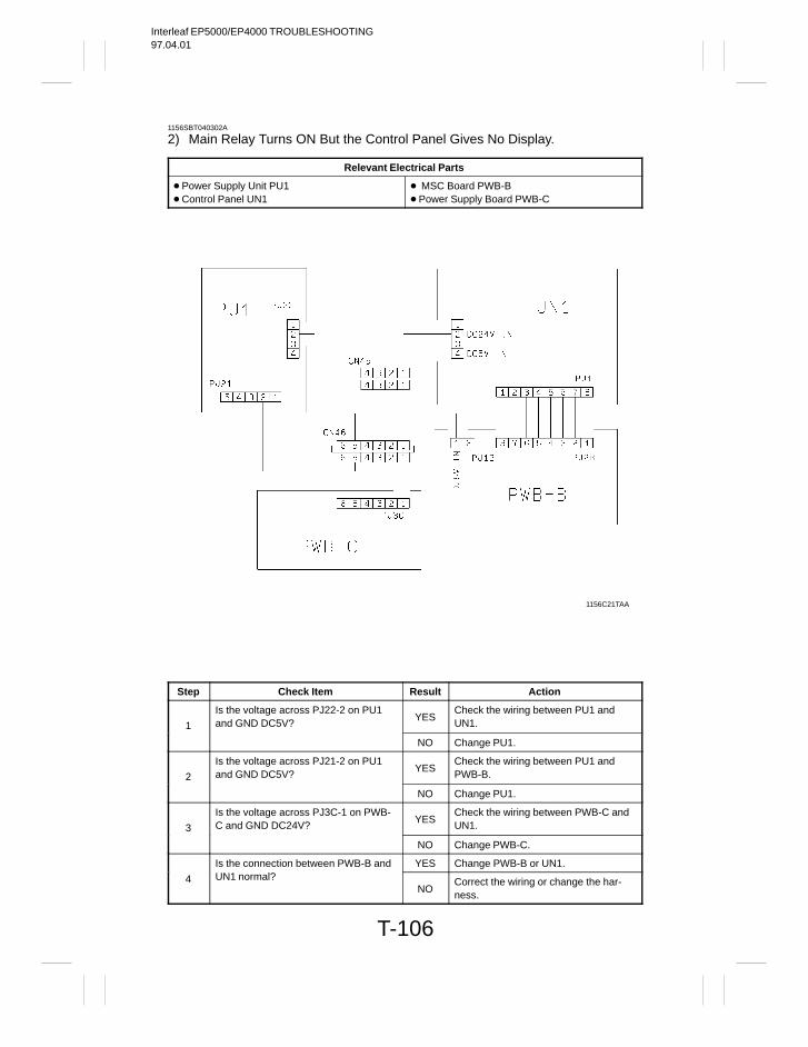
Interleaf EP5000/EP4000 TROUBLESHOOTING97.04.01
T-106
1156SBT040302A
2) Main Relay Turns ON But the Control Panel Gives No Display.
Relevant Electrical Parts
Power Supply Unit PU1 Control Panel UN1
MSC Board PWB-B Power Supply Board PWB-C
1156C21TAA
Step Check Item Result Action
1
Is the voltage across PJ22-2 on PU1and GND DC5V?
YESCheck the wiring between PU1 andUN1.
NO Change PU1.
2
Is the voltage across PJ21-2 on PU1and GND DC5V?
YESCheck the wiring between PU1 andPWB-B.
NO Change PU1.
3
Is the voltage across PJ3C-1 on PWB-C and GND DC24V?
YESCheck the wiring between PWB-C andUN1.
NO Change PWB-C.
Is the connection between PWB-B and YES Change PWB-B or UN1.
4 UN1 normal?NO
Correct the wiring or change the har-ness.
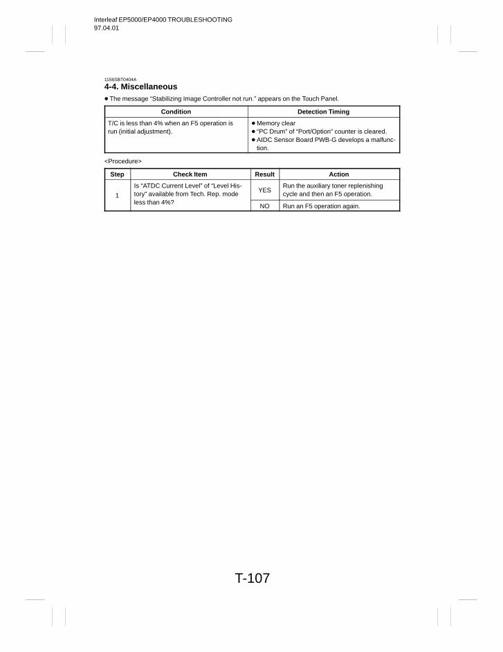
Interleaf EP5000/EP4000 TROUBLESHOOTING97.04.01
T-107
1156SBT0404A
4-4. Miscellaneous The message “Stabilizing Image Controller not run.” appears on the Touch Panel.
Condition Detection Timing
T/C is less than 4% when an F5 operation isrun (initial adjustment).
Memory clear “PC Drum” of “Port/Option” counter is cleared. AIDC Sensor Board PWB-G develops a malfunc-
tion.
<Procedure>
Step Check Item Result Action
1
Is “ATDC Current Level” of “Level His-tory” available from Tech. Rep. mode
YESRun the auxiliary toner replenishingcycle and then an F5 operation.
less than 4%?NO Run an F5 operation again.
Interleaf EP5000/EP4000 TROUBLESHOOTING97.04.01
T-108
1149SAT0500A
IMAGE FAILURE51149SBT0501A
5-1. Image Failure TroubleshootingImage failures have many possible causes. For troubleshooting, it is necessary to determine whether a fail-ure is attributable to a basic cause or any other cause.
In this chapter, troubleshooting is divided into “initial checks” and “troubleshooting procedures classified byimage failure”. If an image failure has occurred, first make the initial checks, then proceed to the correspond-ing image failure troubleshooting procedure.
1149SBT0502A
5-2. Initial Checks
1) Place of installation Is the source voltage normal? Does the voltage vary greatly? Is the copier installed in a hot, humid place or in a place where temperatures vary sharply? Is the copier installed in a dusty place? Is the copier subjected to direct sunlight? Is the copier level?
2) Copy paper Is the recommended paper used?Load recommended paper and make copies to see if the problem persists.
Is the paper damp?Load new paper and make copies to see if the problem persists.
3) Original Does the original used have a reddish background or is it written in light pencil?Use the Test Chart to check the image.
Is the original transparent or are transparencies being used?Cover with white paper and make a copy.
Are the Original Glass and ADF Transport Belt dirty or scratched?If dirty, clean with alcohol. If scratched, replace.
4) Adjust data and Level History data Are the set values of “Adjust” and “Level History (ATDC Level)” in the Tech. Rep. mode equal to the value
given on the Adjust Label inside the Front Door?When installing the Developing Unit of another copier containing its own developer, input the ATDC Lev-
el value of that particular copier.
5) PM parts (supplies) Have the PM parts (supplies), such as the PC Drum, Cleaning Blade, AIDC Sensor and corona wires,
reached the end of their cleaning/replacement cycles?

Interleaf EP5000/EP4000 TROUBLESHOOTING97.04.01
T-109
6) Adjustment items (registration, focus, AE level, etc.) Among the adjustment items given in DIS/REASSEMBLY, ADJUSTMENT, is there any adjustment that
may remedy the image failure?
7) Controller Board Check Is a malfunction code displayed when “Controller Board Check” in the Tech. Rep. mode is run?
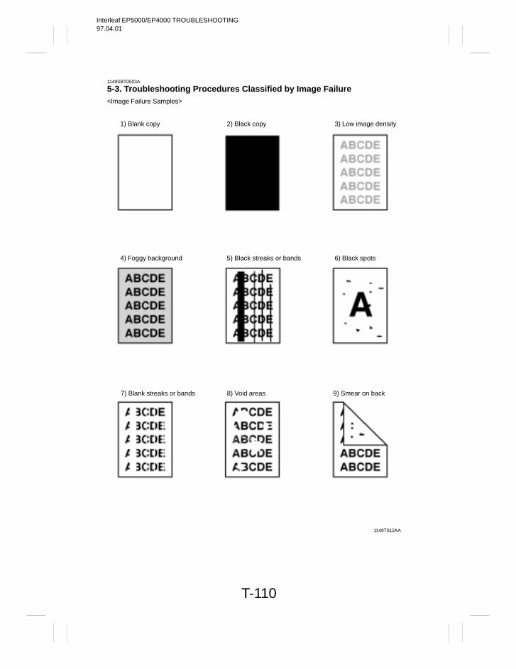
Interleaf EP5000/EP4000 TROUBLESHOOTING97.04.01
T-110
1149SBT0503A
5-3. Troubleshooting Procedures Classified by Image Failure<Image Failure Samples>
1) Blank copy 3) Low image density2) Black copy
1149T012AA
4) Foggy background 6) Black spots5) Black streaks or bands
7) Blank streaks or bands 8) Void areas 9) Smear on back
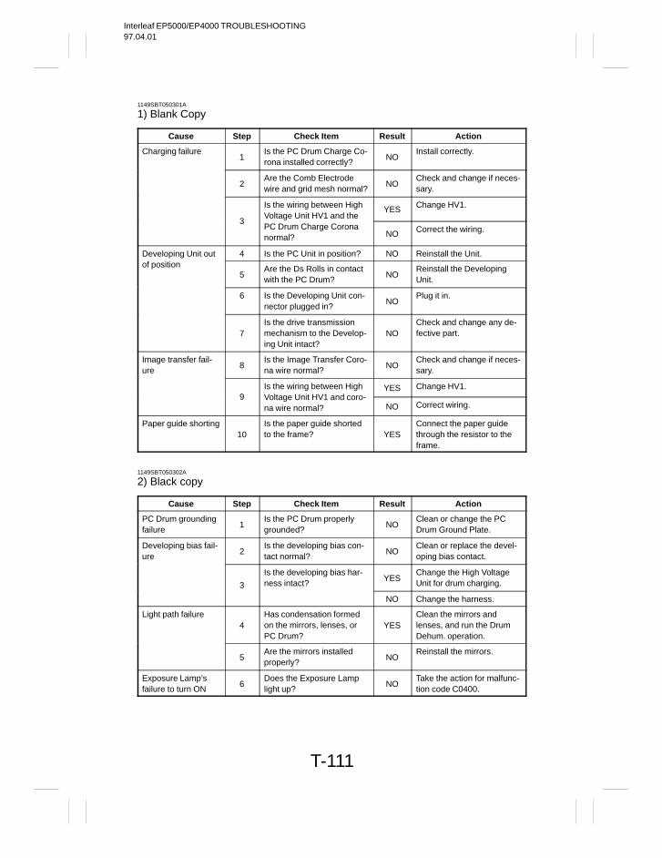
Interleaf EP5000/EP4000 TROUBLESHOOTING97.04.01
T-111
1149SBT050301A
1) Blank Copy
Cause Step Check Item Result Action
Charging failure1
Is the PC Drum Charge Co-rona installed correctly?
NOInstall correctly.
2Are the Comb Electrodewire and grid mesh normal?
NOCheck and change if neces-sary.
Is the wiring between HighVoltage Unit HV1 and the
YES Change HV1.
3PC Drum Charge Coronanormal? NO Correct the wiring.
Developing Unit out 4 Is the PC Unit in position? NO Reinstall the Unit.of position
5Are the Ds Rolls in contactwith the PC Drum?
NOReinstall the DevelopingUnit.
6 Is the Developing Unit con-nector plugged in?
NOPlug it in.
7Is the drive transmissionmechanism to the Develop-ing Unit intact?
NOCheck and change any de-fective part.
Image transfer fail-ure
8Is the Image Transfer Coro-na wire normal?
NOCheck and change if neces-sary.
Is the wiring between High YES Change HV1.9 Voltage Unit HV1 and coro-
na wire normal? NO Correct wiring.
Paper guide shorting10
Is the paper guide shortedto the frame? YES
Connect the paper guidethrough the resistor to theframe.
1149SBT050302A
2) Black copy
Cause Step Check Item Result Action
PC Drum groundingfailure
1Is the PC Drum properlygrounded?
NOClean or change the PCDrum Ground Plate.
Developing bias fail-ure
2Is the developing bias con-tact normal?
NOClean or replace the devel-oping bias contact.
3
Is the developing bias har-ness intact?
YESChange the High VoltageUnit for drum charging.
NO Change the harness.
Light path failure4
Has condensation formedon the mirrors, lenses, orPC Drum?
YESClean the mirrors andlenses, and run the DrumDehum. operation.
5Are the mirrors installedproperly?
NOReinstall the mirrors.
Exposure Lamp’sfailure to turn ON
6Does the Exposure Lamplight up?
NOTake the action for malfunc-tion code C0400.
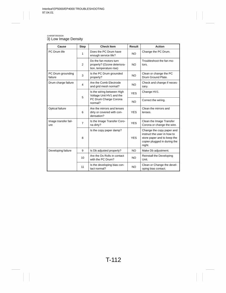
Interleaf EP5000/EP4000 TROUBLESHOOTING97.04.01
T-112
1149SBT050303A
3) Low Image Density
Cause Step Check Item Result Action
PC Drum life1
Does the PC Drum haveenough service life?
NOChange the PC Drum.
2Do the fan motors turnproperly? (Ozone deteriora-tion, temperature rise)
NOTroubleshoot the fan mo-tors.
PC Drum groundingfailure
3Is the PC Drum groundedproperly?
NOClean or change the PCDrum Ground Plate.
Drum charge failure4
Are the Comb Electrodeand grid mesh normal?
NOCheck and change if neces-sary.
Is the wiring between HighVoltage Unit HV1 and the
YES Change HV1.
5PC Drum Charge Coronanormal? NO Correct the wiring.
Optical failure6
Are the mirrors and lensesdirty or covered with con-densation?
YESClean the mirrors andlenses.
Image transfer fail-ure
7Is the Image Transfer Coro-na dirty?
YESClean the Image TransferCorona or change the wire.
8
Is the copy paper damp?
YES
Change the copy paper andinstruct the user in how tostore paper and to keep thecopier plugged in during thenight.
Developing failure 9 Is Db adjusted properly? NO Make Db adjustment.
10Are the Ds Rolls in contactwith the PC Drum?
NOReinstall the DevelopingUnit.
11Is the developing bias con-tact normal?
NOClean or Change the devel-oping bias contact.
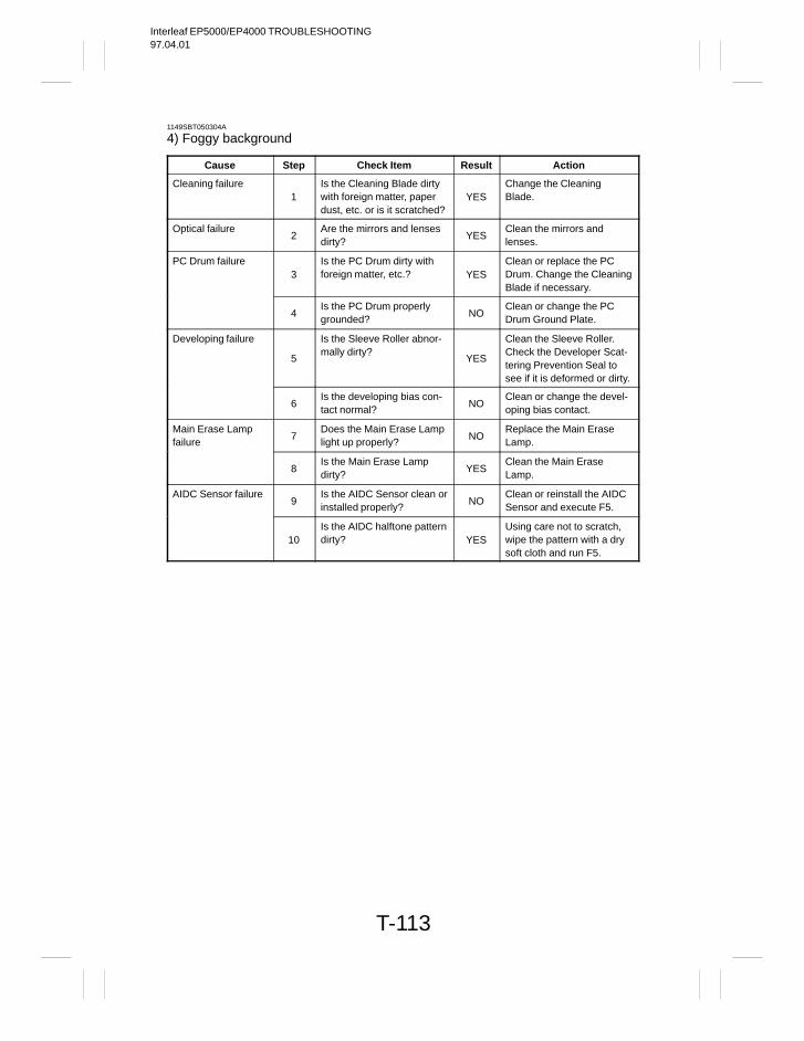
Interleaf EP5000/EP4000 TROUBLESHOOTING97.04.01
T-113
1149SBT050304A
4) Foggy background
Cause Step Check Item Result Action
Cleaning failure1
Is the Cleaning Blade dirtywith foreign matter, paperdust, etc. or is it scratched?
YESChange the CleaningBlade.
Optical failure2
Are the mirrors and lensesdirty?
YESClean the mirrors andlenses.
PC Drum failure3
Is the PC Drum dirty withforeign matter, etc.? YES
Clean or replace the PCDrum. Change the CleaningBlade if necessary.
4Is the PC Drum properlygrounded?
NOClean or change the PCDrum Ground Plate.
Developing failure
5
Is the Sleeve Roller abnor-mally dirty?
YES
Clean the Sleeve Roller.Check the Developer Scat-tering Prevention Seal tosee if it is deformed or dirty.
6Is the developing bias con-tact normal?
NOClean or change the devel-oping bias contact.
Main Erase Lampfailure
7Does the Main Erase Lamplight up properly?
NOReplace the Main EraseLamp.
8Is the Main Erase Lampdirty?
YESClean the Main EraseLamp.
AIDC Sensor failure9
Is the AIDC Sensor clean orinstalled properly?
NOClean or reinstall the AIDCSensor and execute F5.
10Is the AIDC halftone patterndirty? YES
Using care not to scratch,wipe the pattern with a drysoft cloth and run F5.
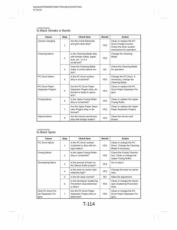
Interleaf EP5000/EP4000 TROUBLESHOOTING97.04.01
T-114
1149SBT050305A
5) Black Streaks or Bands
Cause Step Check Item Result Action
Uneven charging
1
Are the Comb Electrodeand grid mesh dirty?
YES
Clean or replace the PCDrum Charge Corona.Check the toner suctionmechanism for operation.
Cleaning failure
2
Is the Cleaning Blade dirtywith foreign matter, paperdust, etc., or is itscratched?
YES
Change the CleaningBlade.
3Does the Cleaning Blademake a correct lateral mo-tion?
NOCheck the Cleaning Bladefor operation.
PC Drum failure4
Is the PC Drum surfacedirty or scratched? YES
Change the PC Drum. Ifnecessary, change theCleaning Blade.
PC Drum PaperSeparator Fingers
5
Are the PC Drum PaperSeparator Fingers dirty, de-formed or faulty in opera-tion?
YES
Clean or replace the PCDrum Paper Separator Fin-gers.
Fusing failure6
Is the Upper Fusing Rollerdirty or scratched?
YESClean or replace the UpperFusing Roller.
7Are the Upper Paper Sepa-rator Fingers dirty or de-formed?
YESClean or replace the UpperPaper Separator Fingers.
Optical failure8
Are the mirrors and lensesdirty with foreign matter?
YESClean the mirrors andlenses.
1149SBT050306A
6) Black Spots
Cause Step Check Item Result Action
PC Drum failure1
Is the PC Drum surfacescratched or dirty with for-eign matter?
YESClean or change the PCDrum. Change the CleaningBlade if necessary.
Fusing failure2
Is the Upper Fusing Rollerdirty or scratched? YES
Check the Fusing Thermis-tors. Clean or change theUpper Fusing Roller.
Developing failure3
Is the amount of toner onthe Sleeve Roller proper?
YESGo to step 5.
4Is the toner-to-carrier ratiorelatively high?
YESChange the toner-to-carrierratio.
5 Is the Db value normal? NO Make Db adjustment.
6Is the Developer ScatteringPrevention Seal deformedor dirty?
YESClean or change the Devel-oper Scattering PreventionSeal.
Dirty PC Drum Pa-per Separator Fin-gers
7Are the PC Drum PaperSeparator Fingers dirty ordeformed?
YESClean or change the PCDrum Paper Separator Fin-gers.
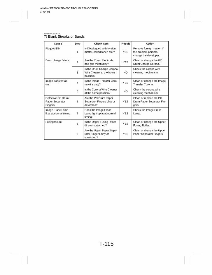
Interleaf EP5000/EP4000 TROUBLESHOOTING97.04.01
T-115
1149SBT050307A
7) Blank Streaks or Bands
Cause Step Check Item Result Action
Plugged Db1
Is Db plugged with foreignmatter, caked toner, etc.? YES
Remove foreign matter. Ifthe problem persists,change the developer.
Drum charge failure2
Are the Comb Electrodeand grid mesh dirty?
YESClean or change the PCDrum Charge Corona.
3Is the Drum Charge CoronaWire Cleaner at the homeposition?
NOCheck the corona wirecleaning mechanism.
Image transfer fail-ure
4Is the Image Transfer Coro-na wire dirty?
YESClean or change the ImageTransfer Corona.
5Is the Corona Wire Cleanerat the home position?
NOCheck the corona wirecleaning mechanism.
Defective PC DrumPaper SeparatorFingers
6Are the PC Drum PaperSeparator Fingers dirty ordeformed?
YESClean or replace the PCDrum Paper Separator Fin-gers.
Image Erase Lamplit at abnormal timing 7
Does the Image EraseLamp light up at abnormaltiming?
YESCheck the Image EraseLamp.
Fusing failure8
Is the Upper Fusing Rollerdirty or scratched?
YESClean or change the UpperFusing Roller.
9Are the Upper Paper Sepa-rator Fingers dirty orscratched?
YESClean or change the UpperPaper Separator Fingers.
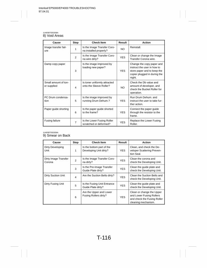
Interleaf EP5000/EP4000 TROUBLESHOOTING97.04.01
T-116
1149SBT050308A
8) Void Areas
Cause Step Check Item Result Action
Image transfer fail-ure
1Is the Image Transfer Coro-na installed properly?
NOReinstall.
2Is the Image Transfer Coro-na wire dirty?
YESClean or change the ImageTransfer Corona wire.
Damp copy paper
3
Is the image improved byloading new paper?
YES
Change the copy paper andinstruct the user in how tostore paper and to keep thecopier plugged in during thenight.
Small amount of ton-er supplied
4
Is toner uniformly attractedonto the Sleeve Roller?
NO
Check the Db value andamount of developer, andcheck the Bucket Roller foroperation.
PC Drum condensa-tion 5
Is the image improved byrunning Drum Dehum.? YES
Run Drum Dehum. andinstruct the user to take fur-ther action.
Paper guide shorting6
Is the paper guide shortedto the frame? YES
Connect the paper guidethrough the resistor to theframe.
Fusing failure7
Is the Lower Fusing Rollerscratched or deformed?
YESReplace the Lower FusingRoller.
1149SBT050309A
9) Smear on Back
Cause Step Check Item Result Action
Dirty DevelopingUnit 1
Is the bottom part of theDeveloping Unit dirty? YES
Clean, and check the De-veloper Scattering Preven-tion Seal.
Dirty Image TransferCorona
2Is the Image Transfer Coro-na dirty?
YESClean the corona andcheck the Developing Unit.
3Is the Pre-Image TransferGuide Plate dirty?
YESClean the guide plate andcheck the Developing Unit.
Dirty Suction Unit4
Are the Suction Belts dirty?YES
Clean the Suction Belts andcheck the Developing Unit.
Dirty Fusing Unit5
Is the Fusing Unit EntranceGuide Plate dirty?
YESClean the guide plate andcheck the Developing Unit.
6
Are the Upper and LowerFusing Rollers dirty?
YES
Clean or change the Upperand Lower Fusing Rollersand check the Fusing Rollercleaning mechanism.

Interleaf EP5000/EP4000 TROUBLESHOOTING97.04.01
Copyright1997 MINOLTA Co., Ltd.
Printed in Japan
Use of this manual shouldbe strictly supervised to avoid disclosure of confidential information.
1156-7998-11 97046000
1156SBT000EA