Embed Size (px)
Citation preview
Fruit Flies Modulate Passive Wing Pitching to Generate In-Flight Turns
Attila J. Bergou,1,* Leif Ristroph,1 John Guckenheimer,2 Itai Cohen,1 and Z. Jane Wang3,†
1Department of Physics, Cornell University, Ithaca, New York 14853, USA2Department of Mathematics, Cornell University, Ithaca, New York 14853, USA
3Theoretical and Applied Mechanics, Cornell University, Ithaca, New York 14853, USA(Received 4 October 2009; published 5 April 2010)
Flying insects execute aerial maneuvers through subtle manipulations of their wing motions. Here, we
measure the free-flight kinematics of fruit flies and determine how they modulate their wing pitching to
induce sharp turns. By analyzing the torques these insects exert to pitch their wings, we infer that the wing
hinge acts as a torsional spring that passively resists the wing’s tendency to flip in response to aerodynamic
and inertial forces. To turn, the insects asymmetrically change the spring rest angles to generate
asymmetric rowing motions of their wings. Thus, insects can generate these maneuvers using only a
slight active actuation that biases their wing motion.
DOI: 10.1103/PhysRevLett.104.148101 PACS numbers: 87.19.lu, 47.85.Gj, 87.85.G�
To generate the vertical force necessary to sustain flight,small insects must beat their wings hundreds of times persecond. Under this constraint, how do they manipulatethese fast wing motions to induce flight maneuvers?Although recent studies have made progress addressinghow wing motions generate aerodynamic forces [1–4],understanding how the wing motions themselves ariseand what control variables govern them remains achallenge. Here, we analyze the torques fruit flies (D.melanoaster) exert to move their wings during sharp-turning flight. We use a moving light pattern to visuallystimulate 10 such maneuvers from distinct flies [5] andmeasure their wing and body kinematics. By using a modelof the aerodynamic forces on flapping wings, we extractthe torques the insects exert to generate the wing motions.From these torques, we construct a mechanical model ofthe wing rotation joints that demonstrates how the interplayof aerodynamic, inertial and biomechanical forces gener-ate the wing kinematics. Finally, we connect this model tothe yaw dynamics of flies and describe the wing actuationmechanism that unifies these maneuvers.
To quantify the turning kinematics of fruit flies, we firstuse three orthogonal cameras to capture their flight at 8000frames per second or about 35 frames for each wing beat[5]. The three-dimensional wing and body motion of theflies is then reconstructed from these videos using Hullreconstruction motion tracking (HRMT) [6]. In what fol-lows, we analyze turns ranging between 5� and 120� andpresent details of the analysis for the largest of these. Thebody kinematics, described by the centroid coordinates andthree Euler angles—yaw, �b, body pitch, �b, and roll, c b,during a turn are shown in Fig. 1(a) and visualized inFig. 1(b). During the level flight, the fly performs a 120�turn in 80 ms, or 18 wing beats. To induce such a turn, theinsect generates differences between the motion of its leftand right wings. We quantify these changes by plotting inFig. 1(c) the time course of three Euler angles—stroke, �,
deviation, �, and wing pitch, c—that describes the orien-tation of the wings relative to the hinges about which theyrotate. A three-dimensional representation of a typicalwing stroke is shown in Fig. 1(d).During the maneuver, asymmetries appear in all three
wing angle kinematics, however, not all of these are in-volved in inducing the turn. For example, the most appar-ent asymmetry—the shift in the mean stroke angles of thewings—simply reorients the aerodynamic forces about theyaw axis of the fly and does not affect the torque thatcauses the turn. To gauge the importance of the wingmotion asymmetries for inducing the turn, we use a qua-sisteady aerodynamic model [7] to determine the averageyaw torque generated by the wing beats from t ¼10–30 ms, when the fly begins to turn. We compare thisvalue to the torque generated by wing motions for whichtwo of the three wing angle kinematics are symmetrized tothe left-right average, isolating the asymmetry in the third.The asymmetry between the wing pitch angles alone gen-erates a yaw torque that is 98% of the total torque gener-ated when all the asymmetries are present. The other 2degrees of freedom generate less than 3% of the totaltorque. These results indicate that the fly manipulates itswing pitch to induce the turn.To quantify the wing pitch asymmetry that induces the
turn, we phase average [8] the strokes from t ¼ 10–30 ms[Fig. 1(e)]. We find that, on the front stroke, the right wingflaps with an average midstroke angle of attack of � ¼ 49�while, on the back stroke, it flaps with� ¼ 40�. The higher� on the front stroke indicates that a larger area of the wingis presented to the flow, resulting in a larger drag force.This force causes average yaw torques of �19:7 and14:7 nNm, respectively, on the front and back strokesthat turn the fly rightward. The left wing flaps with � ¼48�, for the front-stroke, and � ¼ 50�, for the back stroke,generating average yaw torques of 21:7 and �22:5 nNm,respectively. Because of the close values of � during the
PRL 104, 148101 (2010) P HY S I CA L R EV I EW LE T T E R Sweek ending9 APRIL 2010
0031-9007=10=104(14)=148101(4) 148101-1 � 2010 The American Physical Society
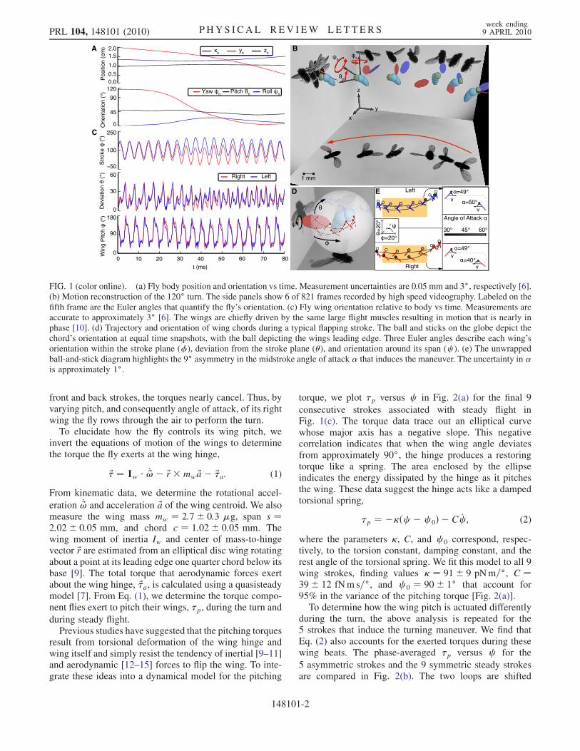
front and back strokes, the torques nearly cancel. Thus, byvarying pitch, and consequently angle of attack, of its rightwing the fly rows through the air to perform the turn.
To elucidate how the fly controls its wing pitch, weinvert the equations of motion of the wings to determinethe torque the fly exerts at the wing hinge,
~� ¼ Iw � _~!� ~r�mw ~a� ~�a: (1)
From kinematic data, we determine the rotational accel-
eration _~! and acceleration ~a of the wing centroid. We alsomeasure the wing mass mw ¼ 2:7� 0:3 �g, span s ¼2:02� 0:05 mm, and chord c ¼ 1:02� 0:05 mm. Thewing moment of inertia Iw and center of mass-to-hingevector ~r are estimated from an elliptical disc wing rotatingabout a point at its leading edge one quarter chord below itsbase [9]. The total torque that aerodynamic forces exertabout the wing hinge, ~�a, is calculated using a quasisteadymodel [7]. From Eq. (1), we determine the torque compo-nent flies exert to pitch their wings, �p, during the turn and
during steady flight.Previous studies have suggested that the pitching torques
result from torsional deformation of the wing hinge andwing itself and simply resist the tendency of inertial [9–11]and aerodynamic [12–15] forces to flip the wing. To inte-grate these ideas into a dynamical model for the pitching
torque, we plot �p versus c in Fig. 2(a) for the final 9
consecutive strokes associated with steady flight inFig. 1(c). The torque data trace out an elliptical curvewhose major axis has a negative slope. This negativecorrelation indicates that when the wing angle deviatesfrom approximately 90�, the hinge produces a restoringtorque like a spring. The area enclosed by the ellipseindicates the energy dissipated by the hinge as it pitchesthe wing. These data suggest the hinge acts like a dampedtorsional spring,
�p ¼ ��ðc � c 0Þ � C _c ; (2)
where the parameters �, C, and c 0 correspond, respec-tively, to the torsion constant, damping constant, and therest angle of the torsional spring. We fit this model to all 9wing strokes, finding values � ¼ 91� 9 pNm=�, C ¼39� 12 fNm s=�, and c 0 ¼ 90� 1� that account for95% in the variance of the pitching torque [Fig. 2(a)].To determine how the wing pitch is actuated differently
during the turn, the above analysis is repeated for the5 strokes that induce the turning maneuver. We find thatEq. (2) also accounts for the exerted torques during thesewing beats. The phase-averaged �p versus c for the
5 asymmetric strokes and the 9 symmetric steady strokesare compared in Fig. 2(b). The two loops are shifted
FIG. 1 (color online). (a) Fly body position and orientation vs time. Measurement uncertainties are 0.05 mm and 3�, respectively [6].(b) Motion reconstruction of the 120� turn. The side panels show 6 of 821 frames recorded by high speed videography. Labeled on thefifth frame are the Euler angles that quantify the fly’s orientation. (c) Fly wing orientation relative to body vs time. Measurements areaccurate to approximately 3� [6]. The wings are chiefly driven by the same large flight muscles resulting in motion that is nearly inphase [10]. (d) Trajectory and orientation of wing chords during a typical flapping stroke. The ball and sticks on the globe depict thechord’s orientation at equal time snapshots, with the ball depicting the wings leading edge. Three Euler angles describe each wing’sorientation within the stroke plane (�), deviation from the stroke plane (�), and orientation around its span (c ). (e) The unwrappedball-and-stick diagram highlights the 9� asymmetry in the midstroke angle of attack � that induces the maneuver. The uncertainty in �is approximately 1�.
PRL 104, 148101 (2010) P HY S I CA L R EV I EW LE T T E R Sweek ending9 APRIL 2010
148101-2
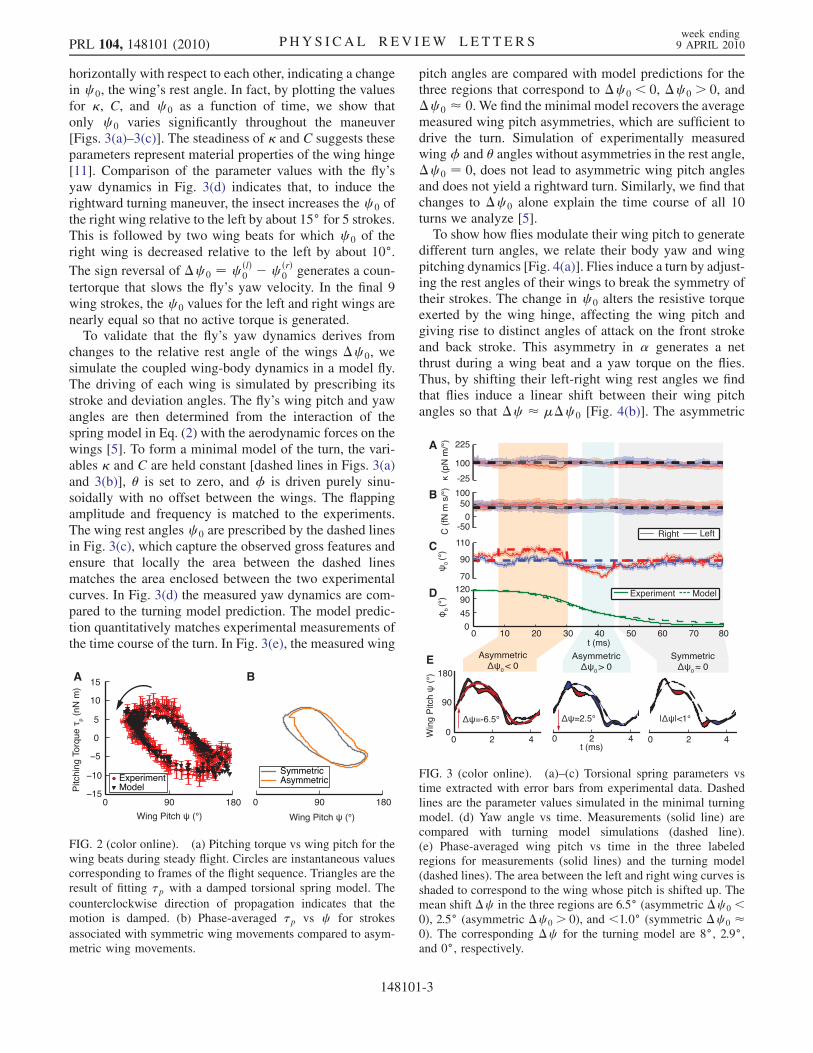
horizontally with respect to each other, indicating a changein c 0, the wing’s rest angle. In fact, by plotting the valuesfor �, C, and c 0 as a function of time, we show thatonly c 0 varies significantly throughout the maneuver[Figs. 3(a)–3(c)]. The steadiness of � and C suggests theseparameters represent material properties of the wing hinge[11]. Comparison of the parameter values with the fly’syaw dynamics in Fig. 3(d) indicates that, to induce therightward turning maneuver, the insect increases the c 0 ofthe right wing relative to the left by about 15� for 5 strokes.This is followed by two wing beats for which c 0 of theright wing is decreased relative to the left by about 10�.The sign reversal of �c 0 ¼ c ðlÞ
0 � c ðrÞ0 generates a coun-
tertorque that slows the fly’s yaw velocity. In the final 9wing strokes, the c 0 values for the left and right wings arenearly equal so that no active torque is generated.
To validate that the fly’s yaw dynamics derives fromchanges to the relative rest angle of the wings �c 0, wesimulate the coupled wing-body dynamics in a model fly.The driving of each wing is simulated by prescribing itsstroke and deviation angles. The fly’s wing pitch and yawangles are then determined from the interaction of thespring model in Eq. (2) with the aerodynamic forces on thewings [5]. To form a minimal model of the turn, the vari-ables � and C are held constant [dashed lines in Figs. 3(a)and 3(b)], � is set to zero, and � is driven purely sinu-soidally with no offset between the wings. The flappingamplitude and frequency is matched to the experiments.The wing rest angles c 0 are prescribed by the dashed linesin Fig. 3(c), which capture the observed gross features andensure that locally the area between the dashed linesmatches the area enclosed between the two experimentalcurves. In Fig. 3(d) the measured yaw dynamics are com-pared to the turning model prediction. The model predic-tion quantitatively matches experimental measurements ofthe time course of the turn. In Fig. 3(e), the measured wing
pitch angles are compared with model predictions for thethree regions that correspond to �c 0 < 0, �c 0 > 0, and�c 0 � 0. We find the minimal model recovers the averagemeasured wing pitch asymmetries, which are sufficient todrive the turn. Simulation of experimentally measuredwing� and � angles without asymmetries in the rest angle,�c 0 ¼ 0, does not lead to asymmetric wing pitch anglesand does not yield a rightward turn. Similarly, we find thatchanges to �c 0 alone explain the time course of all 10turns we analyze [5].To show how flies modulate their wing pitch to generate
different turn angles, we relate their body yaw and wingpitching dynamics [Fig. 4(a)]. Flies induce a turn by adjust-ing the rest angles of their wings to break the symmetry oftheir strokes. The change in c 0 alters the resistive torqueexerted by the wing hinge, affecting the wing pitch andgiving rise to distinct angles of attack on the front strokeand back stroke. This asymmetry in � generates a netthrust during a wing beat and a yaw torque on the flies.Thus, by shifting their left-right wing rest angles we findthat flies induce a linear shift between their wing pitchangles so that �c � ��c 0 [Fig. 4(b)]. The asymmetric
FIG. 2 (color online). (a) Pitching torque vs wing pitch for thewing beats during steady flight. Circles are instantaneous valuescorresponding to frames of the flight sequence. Triangles are theresult of fitting �p with a damped torsional spring model. The
counterclockwise direction of propagation indicates that themotion is damped. (b) Phase-averaged �p vs c for strokes
associated with symmetric wing movements compared to asym-metric wing movements.
FIG. 3 (color online). (a)–(c) Torsional spring parameters vstime extracted with error bars from experimental data. Dashedlines are the parameter values simulated in the minimal turningmodel. (d) Yaw angle vs time. Measurements (solid line) arecompared with turning model simulations (dashed line).(e) Phase-averaged wing pitch vs time in the three labeledregions for measurements (solid lines) and the turning model(dashed lines). The area between the left and right wing curves isshaded to correspond to the wing whose pitch is shifted up. Themean shift �c in the three regions are 6.5� (asymmetric �c 0 <0), 2.5� (asymmetric �c 0 > 0), and <1:0� (symmetric �c 0 �0). The corresponding �c for the turning model are 8�, 2.9�,and 0�, respectively.
PRL 104, 148101 (2010) P HY S I CA L R EV I EW LE T T E R Sweek ending9 APRIL 2010
148101-3
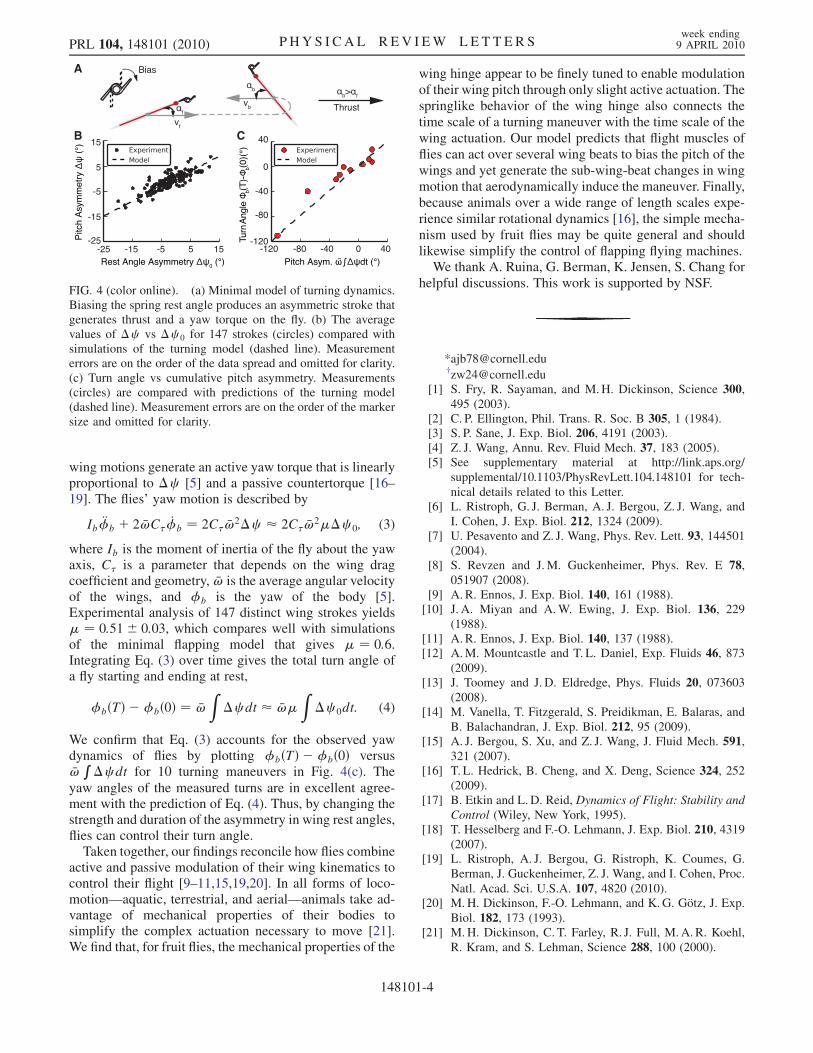
wing motions generate an active yaw torque that is linearlyproportional to �c [5] and a passive countertorque [16–19]. The flies’ yaw motion is described by
Ib €�b þ 2 �!C�_�b ¼ 2C� �!
2�c � 2C� �!2��c 0; (3)
where Ib is the moment of inertia of the fly about the yawaxis, C� is a parameter that depends on the wing dragcoefficient and geometry, �! is the average angular velocityof the wings, and �b is the yaw of the body [5].Experimental analysis of 147 distinct wing strokes yields� ¼ 0:51� 0:03, which compares well with simulationsof the minimal flapping model that gives � ¼ 0:6.Integrating Eq. (3) over time gives the total turn angle ofa fly starting and ending at rest,
�bðTÞ ��bð0Þ ¼ �!Z
�c dt � �!�Z
�c 0dt: (4)
We confirm that Eq. (3) accounts for the observed yawdynamics of flies by plotting �bðTÞ ��bð0Þ versus�!R�c dt for 10 turning maneuvers in Fig. 4(c). The
yaw angles of the measured turns are in excellent agree-ment with the prediction of Eq. (4). Thus, by changing thestrength and duration of the asymmetry in wing rest angles,flies can control their turn angle.
Taken together, our findings reconcile how flies combineactive and passive modulation of their wing kinematics tocontrol their flight [9–11,15,19,20]. In all forms of loco-motion—aquatic, terrestrial, and aerial—animals take ad-vantage of mechanical properties of their bodies tosimplify the complex actuation necessary to move [21].We find that, for fruit flies, the mechanical properties of the
wing hinge appear to be finely tuned to enable modulationof their wing pitch through only slight active actuation. Thespringlike behavior of the wing hinge also connects thetime scale of a turning maneuver with the time scale of thewing actuation. Our model predicts that flight muscles offlies can act over several wing beats to bias the pitch of thewings and yet generate the sub-wing-beat changes in wingmotion that aerodynamically induce the maneuver. Finally,because animals over a wide range of length scales expe-rience similar rotational dynamics [16], the simple mecha-nism used by fruit flies may be quite general and shouldlikewise simplify the control of flapping flying machines.We thank A. Ruina, G. Berman, K. Jensen, S. Chang for
helpful discussions. This work is supported by NSF.
*[email protected]†[email protected]
[1] S. Fry, R. Sayaman, and M.H. Dickinson, Science 300,495 (2003).
[2] C. P. Ellington, Phil. Trans. R. Soc. B 305, 1 (1984).[3] S. P. Sane, J. Exp. Biol. 206, 4191 (2003).[4] Z. J. Wang, Annu. Rev. Fluid Mech. 37, 183 (2005).[5] See supplementary material at http://link.aps.org/
supplemental/10.1103/PhysRevLett.104.148101 for tech-
nical details related to this Letter.[6] L. Ristroph, G. J. Berman, A. J. Bergou, Z. J. Wang, and
I. Cohen, J. Exp. Biol. 212, 1324 (2009).[7] U. Pesavento and Z. J. Wang, Phys. Rev. Lett. 93, 144501
(2004).[8] S. Revzen and J.M. Guckenheimer, Phys. Rev. E 78,
051907 (2008).[9] A. R. Ennos, J. Exp. Biol. 140, 161 (1988).[10] J. A. Miyan and A.W. Ewing, J. Exp. Biol. 136, 229
(1988).[11] A. R. Ennos, J. Exp. Biol. 140, 137 (1988).[12] A.M. Mountcastle and T. L. Daniel, Exp. Fluids 46, 873
(2009).[13] J. Toomey and J. D. Eldredge, Phys. Fluids 20, 073603
(2008).[14] M. Vanella, T. Fitzgerald, S. Preidikman, E. Balaras, and
B. Balachandran, J. Exp. Biol. 212, 95 (2009).[15] A. J. Bergou, S. Xu, and Z. J. Wang, J. Fluid Mech. 591,
321 (2007).[16] T. L. Hedrick, B. Cheng, and X. Deng, Science 324, 252
(2009).[17] B. Etkin and L.D. Reid, Dynamics of Flight: Stability and
Control (Wiley, New York, 1995).[18] T. Hesselberg and F.-O. Lehmann, J. Exp. Biol. 210, 4319
(2007).[19] L. Ristroph, A. J. Bergou, G. Ristroph, K. Coumes, G.
Berman, J. Guckenheimer, Z. J. Wang, and I. Cohen, Proc.
Natl. Acad. Sci. U.S.A. 107, 4820 (2010).[20] M.H. Dickinson, F.-O. Lehmann, and K.G. Gotz, J. Exp.
Biol. 182, 173 (1993).[21] M.H. Dickinson, C. T. Farley, R. J. Full, M. A. R. Koehl,
R. Kram, and S. Lehman, Science 288, 100 (2000).
FIG. 4 (color online). (a) Minimal model of turning dynamics.Biasing the spring rest angle produces an asymmetric stroke thatgenerates thrust and a yaw torque on the fly. (b) The averagevalues of �c vs �c 0 for 147 strokes (circles) compared withsimulations of the turning model (dashed line). Measurementerrors are on the order of the data spread and omitted for clarity.(c) Turn angle vs cumulative pitch asymmetry. Measurements(circles) are compared with predictions of the turning model(dashed line). Measurement errors are on the order of the markersize and omitted for clarity.
PRL 104, 148101 (2010) P HY S I CA L R EV I EW LE T T E R Sweek ending9 APRIL 2010
148101-4