Embed Size (px)
Citation preview

Nuclear EnergyFrontiers of Physics Lecture 2 (F4) Dan Protopopescu

Nuclear Energy - Frontiers of Physics Course - Lecture 2
Summary of Lecture I
• Nuclear power around the world• Costs, comparisons, advantages• Public perception• Radiation and radioactive material• Nuclear waste• Atomic bombs and nuclear power
plants
Next: the Fukushima Daiichi accident ...
2

Nuclear Energy - Frontiers of Physics Course - Lecture 2
Fukushima Daiichi - 11 March 2011, Ōkuma, Japan
• INES Level 7 accident• Accident type: meltdown, hydrogen
explosion
• Deaths: none• Causes: complex equipment failures
following an earthquake and tsunami
• Earthquake Tōhoku of magnitude 9.0 occurs Friday at 2:46 PM
• Reactors 1, 2 and 3 automatically SCRAM and diesel generators turn on (unit 4 was in cold storage and 5 and 6 were off at the time)
• The situation seems under control• At 3:27 a first wave hits but does
not overtop the seawall• Eight minutes later, a second,15m
high tsunami wave hits BWR
3
Nuclear Energy - Frontiers of Physics Course - Lecture 2
Fukushima Daiichi
4
Imag
e co
urte
sy o
f TE
PC
O p
ublic
info
rmat
ion
web
site

Nuclear Energy - Frontiers of Physics Course - Lecture 2
FD accident: Sequence of events (cont’d)
• Generators, electrical switchgear and external coolant pumps are flooded, power lines are cut
• Un unprecedented station blackout (SBO) results• Reactors overheat due to the natural decay of fission products• Due to the destruction done by the tsunami, it is impossible to cool down the reactors
• During the next hours and days, reactors 1, 2 and 3 experience full meltdown; hydrogen is produced by the oxidation of the zircaloy cladding
• Hydrogen explosions destroy the upper parts of the buildings housing reactors 1, 3, and 4
• Explosions at reactors 1 and 3 damage the secondary containment of reactor 2 and multiple fires break out
• The spent fuel rods in the storage pools overheat as water levels in the pools drop, releasing radioactivity in the atmosphere; tons of water have to be dropped in the pool of reactor 4 by helicopter or water cannon
5

Nuclear Energy - Frontiers of Physics Course - Lecture 2
FD accident: Safety flaws
• The emergency diesel generators and DC batteries - components crucial in powering the reactors' cooling systems in the event of a power loss - were located in the basements of the reactor turbine buildings
• The plant was designed to withstand a 5.7m tsunami, although a study from 2008 indicated that higher waves could be produced by an earthquake in this region
• At reactor 1, the relief valve should have been opened to vent steam and hydrogen. Because this would have also released radioactive material, it was postponed for so long that the reactor ultimately exploded BWR Mark I scheme: RPV - reactor pressure vessel,
SFP - spent fuel pool, DW - dry well, SCSW - secondary concrete shield wall, WW - steam suppression pool
6

Nuclear Energy - Frontiers of Physics Course - Lecture 2
FD accident: Impact
• An area of 20km radius around the plant had to be evacuated• 89,000 people have been displaced, with no possibility of return before less
than 20 years• Significant releases of radioactive pollutants in coastal waters• Releases of 131I and 137Cs are around 10% of the ones from Chernobyl• No deaths or serious injuries due to direct radiation exposure• Estimated that on the order of 1,000 people will die from cancer as a result of
radiation exposure (more than 20,000 died in the earthquake)• Rectors still not in a stable condition, radioactive material still leaking today • High levels of radiation prevent an accurate assessment of the situation• TEPCO is close to insolvency, and will need government money to survive• Increased anti-nuclear sentiment has been evident in many countries among
which Italy, Spain, Switzerland• Germany decided to phase out nuclear plants
7

Reactor TechnologyTypes of reactors, safety considerations, other applications

• Pressurised Water Reactors (PWR) are the most common type built• PWRs were originally designed for nuclear submarines• Water at 15 MPa and 290˚C enters the reactor vessel, is heated as it passes
through the core region and exits at 325˚C
Nuclear Energy - Frontiers of Physics Course - Lecture 2
PWR
• The water is pressurised to minimise the risk of boiling
• A steam generator is then used to transfer this heat
• The steam drives a turbine that turns an electricity generator
Image credits: eia.gov
9

Nuclear Energy - Frontiers of Physics Course - Lecture 2
PWR (cont’d)
• The H2O coolant in a PWR acts also as moderator and reflector
• Slightly enriched uranium, with 235U concentrations of 2–5% is used as fuel
• The fuel is loaded into typically 4m long zircalloy-clad tubes mounted in square clusters
• A typical PWR generates around 3GWt with an ≈33% efficiency
• One of the reasons for the widespread deployment of PWRs is their large negative void coefficient
Image credits: Mitsubishi
10

• Boiling Water Reactors (BWR) have negative void coefficients as well• The boiling water H2O acts as coolant, moderator and reflector• Operates with less water than a PWR in a direct-cycle, i.e. the steam produced in
the core vessel directly turns the turbines
Nuclear Energy - Frontiers of Physics Course - Lecture 2
BWR
• Pressure is about half of that in a PWR
• Reactivity is adjusted via feedwater flow
• Efficiency and fuel similar with PWR
• Steam is radioactive
Image credits: eia.gov
11

• (Pressurised) Heavy Water Reactors use D2O as coolant and moderator• The advantage is that they work with natural (unenriched) uranium, because of
the lower neutron absorption in D2O• The coolant tubes are pressurised,
but not the whole reactor• Small positive void coefficient• Plant efficiency is around 28%• Can be refuelled online• CANDU is the industry standard
Nuclear Energy - Frontiers of Physics Course - Lecture 2
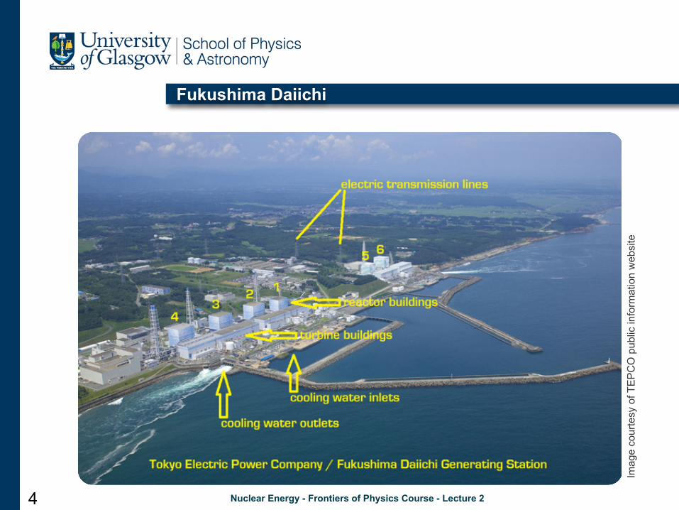
HWR
Imag
e cr
edits
: Wik
iped
ia1 - Fuel bundle, 2 - Rector core vessel, 3 - Control rods, 4 - D2O pressure reservoir, 5 - Steam generator, 6 - H2O pump, 7 - D2O pump, 8 - Online refuelling machine, 9 - D2O moderator, 10 - Pressure tube, 11 - Steam going to the turbine, 12 - Cold water returning from turbine13 - Reinforced concrete containment building
12

Nuclear Energy - Frontiers of Physics Course - Lecture 2
RBMK
• RBMK (standing for High Power Channel-type Reactor) is a Soviet-design, graphite-moderated, boiling water cooled reactor
• Fuel elements are enclosedin pressure tubes
• Runs on natural U, butdoes not require a D2Omoderator
• No containment building• Allows online refuelling• Efficiency at ≈32%• Power output of 1.5GWe• Post-Chernobyl, all RBMK
in operation were updated to increase their safety
13 Imag
e cr
edits
: Wik
iped
ia

• Pressurised Gas-Cooled Reactors mostly of UK design (Magnox)• Use graphite moderator,
CO2 coolant and boron-steel control rods
• Use natural U fuel,in magnesium alloy cladding
• Temperature of CO2
gas is 180˚ to 360˚C• Efficiency of ≈40%• Lower power outputs
up to 215MWe• Operating since 1956,
many now decommissioned
Nuclear Energy - Frontiers of Physics Course - Lecture 2
GCR
Original image: Wikipedia
14

• Advanced Gas-Cooled Reactors are an improved version of the Magnox design• Use the same graphite moderator,
CO2 coolant and boron-steel control rods
• Use low enriched UO2
fuel (2.5-3.5%), in stainless steel cladding
• Have reinforced concrete pressure vessels
• Temperature of CO2
gas is 280˚ to 630˚C• Efficiencies of ≈42%• Higher power outputs
up to 500MWe
Nuclear Energy - Frontiers of Physics Course - Lecture 2
AGCR
Image source: Wikipedia
15

• Liquid Metal Fast Breeder Reactors produce more fuel than they consume• Use liquid metal coolant (Na or Pb), which does not need to be pressurised• Unmoderated (fast n)• Pb is transparent to
neutrons, does not become radioactive, and adds the advantage of excellent radiation shielding. But is toxicand not easy to dispose of
• Most LMFBR use Na, however, sodium explodes in contact with water
• Breeders pose a certain proliferation danger
Nuclear Energy - Frontiers of Physics Course - Lecture 2
LMFBR
Imag
e so
urce
: Wik
iped
ia
16

Nuclear Energy - Frontiers of Physics Course - Lecture 2
Other types
• ABWR (Advanced Boiling Water Reactor) and BWR– has load follow capabilities: using a combination of coolant flow and control rods,
power can be ramped down to 60% of power when demand is low
• MSR (Molten Salt Reactors)– fuel is dissolved in fluoride salts, or use fluoride salts for coolant (e.g. UF4)– no high pressure (they operate at near atmospheric pressures) or flammable
components in the core– many safety features, 0.1% of the radioactive waste of a standard reactor– high efficiency, small core size, suitable for vehicles
• PBR (Pebble Bed Reactor) – gas cooled, standardised fuel molded into ceramic balls– efficient, low-maintenance, very safe reactor with inexpensive fuel
• AHR (Aqueous Homogeneous Reactor)– use soluble nuclear salts dissolved in water and mixed with a coolant and a neutron
moderator– self controlling, safest reactors, but very few were built
17

Nuclear Energy - Frontiers of Physics Course - Lecture 2
Third generation reactors
• Are advanced designs of the Generation II designs (BWR, PWR, AGR, CANDU etc. built until the late 1990s)
• Feature standardised designs that expedite licensing, reduce capital cost and construction time
• A simpler and more rugged design that makes them easier to operate and less vulnerable to operational incidents
• Passive safety systems that rely on gravity, natural convection or resistance to high temperatures and require no active controls or operator intervention to avoid an accident in case of malfunctions
• Higher availability and longer operating life (typically 60 years)• Higher fuel burn-up to reduce fuel use and the amount of waste• Reduced possibility of core meltdowns• Equipped with core-catchers below the reactor vessel• Designed such that following a shutdown the reactors requires no active intervention for
3 days (‘72h grace period’)
• Built to resist an aircraft impact without serious damage that would allow radiological release
18

Nuclear Energy - Frontiers of Physics Course - Lecture 2
Other applications of nuclear energy
• Nuclear power can be used to – generate heat and/or electricity for general use (buried reactor powering remote
villages)– produce hydrogen for fuel cells– desalinate seawater for human consumption
• Propulsion for nuclear ships and submarines– 1 pound of highly enriched U replaces 1,000,000 gallons of gasoline
• Peaceful nuclear explosions – have been used to extinguish gas field fires, for large-scale excavations, create
cavities for underground gas, oil or waste storage – PNEs will be banned under the Comprehensive Nuclear Test-Ban Treaty when it
enters into force
• Production of radioisotopes or nuclear fuel• In space: electric power for satellites and space probes• Accelerator-driven reactors; research reactors
19

• Heat is produced through passive radioactive decay
• Heat is converted to electricity via thermoelectric (Seebeck) effect
• Used to power space probes, remote lighthouses in the arctic etc.
• Power output decreased over time
Nuclear Energy - Frontiers of Physics Course - Lecture 2
RTG
20

Nuclear Energy - Frontiers of Physics Course - Lecture 2
Research reactors
• IBR-2 is a pulsed fast reactor at FLNP/JINR research centre in Dubna, Russia• Reactivity is modulated mechanically
using two nickel-steel rotating reflectors
• Uses PuO2 fuel pellets• Coolant is liquid sodium• Uses multiple moderators, of which
one is water• Average power is 2MW • Pulse frequency 10Hz• Pulse half-width ~200s
1 - Reactor vessel, 2 - Core, 3 - Main movable reflector, 4 - Additional movable reflector, 5 - Moderator, 6 - Stationary reflector, 7,8 - Cooling loops, 9 - Na pump, 10 - Na/Air heat exchanger, 11 - intermediate heat exchanger
21

Future TechnologiesNew technologies and applications, fusion reactors

Nuclear Energy - Frontiers of Physics Course - Lecture 2
Generation IV reactors
• Gas cooled fast reactor– helium-cooled (850˚C), thick steel pressure vessel, breeding core, fast n spectrum
• Lead cooled fast reactor– flexible fast neutron reactor, natural convection cooling, can be built as ‘battery’ unit
• Molten salt reactor (two variants)• Sodium-cooled fast reactor• Supercritical water-cooled reactor
– very high-pressure water coolant, functioning above the thermodynamic critical point of water (374ºC, 22 MPa)
– coolant directly drives the turbine– thermal efficiency ~50% is about one third higher than today's LWRs
• Very high temperature reactor– graphite-moderated, helium-cooled reactors, up to 1000ºC outlet temperatures– can be used for thermochemical hydrogen production via an intermediate heat exchanger,
with electricity cogeneration, or for direct high-efficiency driving of a turbine– completely passive safety, low operation and maintenance costs, modular construction
23

Nuclear Energy - Frontiers of Physics Course - Lecture 2
Planned and future types of nuclear reactors
• Generation VI models proposed for deployment between 2020 and 2030:
24
• Generation V: liquid or gas core reactors, gas core EM, fission-fragment reactors

• Nuclear fusion is the process by which two or more atomic nuclei fuse together to form a single heavier nucleus
• Accompanied by release or absorption of large quantities of energy
• The fusion of nuclei with mass lower than iron (Fe) releases energy
• Fusion is the process that powers active stars or the hydrogen bomb
Nuclear Energy - Frontiers of Physics Course - Lecture 2
Fusion
25
Image credits: renewablepowernews.com

• Imply none of the complexities associated with handling radioactive materials• No CO2 or other atmospheric pollutants, waste products are short-lived• Does not pose a radiation threat, as the plasma will immediately vanish if the
reaction process goes awry• Based on the reaction
• Deuterium is relatively abundant and tritium can be mass-produced in nuclear reactors by enclosing the plasma in a breeder blanket of lithium
• Since the 1950s, several fusion reactors have been built, but as yet none has produced more thermal energy than electrical energy consumed
• Many technical challenges
Nuclear Energy - Frontiers of Physics Course - Lecture 2
Fusion reactors
26

• Where the nuclear fusion reactions are initiated by heating and compressing a fuel target containing a mixture of deuterium and tritium
• Fuel micro-balloons filled with either D and T gas or DT ice– Energy is delivered to the outer layer of the target using high-energy lasers (1)– The heated surface explodes and compresses the inside fuel (2)– During the final part of the capsule implosion, the fuel core reaches 20 times the
density of Pb and ignites at 100,000,000˚C (3)– Thermonuclear burn spreads rapidly through the compressed fuel, yielding many
times the input energy (4)
Nuclear Energy - Frontiers of Physics Course - Lecture 2
Inertial confinement fusion
27Image source: Wikipedia

• Research pioneered by Russians in the late 1950s; First successful test in 1968• Uses a magnetic field to confine a D+T plasma to a toroidal shape and keep it
away from the containment wall• Stable plasma equilibrium is
achieved via a combination of toroidal and poloidal fields
• Plasma high temperatures areachieved via ohmic heating,neutral beam injection or viaRF or microwave heating
• Solid vacuum vessel acts alsoas shielding
• Energy is extracted from theescaping neutrons and transferred to a primary coolant
Nuclear Energy - Frontiers of Physics Course - Lecture 2
Tokamak
28

Nuclear Energy - Frontiers of Physics Course - Lecture 2
Fusion
• Advantages:– virtually zero pollution: no gaseous CO2, SO2 or NOx by-products – produces hundreds of times less radioactive waste than that of a fission reactor– no long-lived radioactive waste– a large-scale runaway chain reaction is impossible. Direct contact with the walls of the
reactor chamber would contaminate the plasma, cooling it down immediately and stopping the fusion process
– the amount of fuel planned to be contained in a fusion reactor chamber is very small (at any given time, ITER’s plasma would contain ~0.5g of D+T fuel, only enough to sustain the reaction for about one hour)
– an accident would release very small amounts of radioactive material
• Technical challenges:– maintain a stable plasma configuration– find materials that can withstand the intense neutron fluxes produced– extract energy for useful purposes– produce sizeably more energy than what is put in
29

Nuclear Energy - Frontiers of Physics Course - Lecture 2
ITER
• Currently leading the effort to commercialise fusion power
• ITER Organisation was established in October 2007 but project dates from 1985
• Members: China, EU, India, Japan, S. Korea, Russia, USA
• The machine is being built now in Cadarache, France
• Project timescale: 30 years• Max. power: 500MW• Fusion energy gain factor Q
between 5 and 10• iter is the Latin for ‘journey’
Original image: ITER
30

Nuclear Energy - Frontiers of Physics Course - Lecture 2
References
• IAEA: www.iaea.org • World Nuclear Association: www.world-nuclear.org• ITER project: www.iter.org• HowStuffWorks.com• Wikipedia• www.tepco.co.jp• For details on the nuclear fuel cycle see David Hamilton’s course:
http://nuclear.gla.ac.uk/twiki/bin/view.pl/Main/NuclearFuelCycle
31
Informal feedback to [email protected]
is more than welcome