Embed Size (px)
Citation preview
From Conceptual Models to Simulation Models:
Model Driven Development of Agent-Based Simulations
Takashi Iba †1
Yoshiaki Matsuzawa †2
Nozomu Aoyama †2
†1 Faculty of Policy Management, Keio University
†2 Graduate School of Media and Governance, Keio University
1 Introduction
Every social issue surrounding us today stemsfrom complex factors. Now we need to estab-lish a trans-disciplinary approach so that wecan examine the flow of interconnected phe-nomena. The solution lies with new methodol-ogy called agent-based modeling. This conceptmakes it possible to model our society as a sys-tem formed by an interaction between numbersof autonomous agents.
In the current state in the study of simulatingagent-based economic models, however, there isa problem that needs to be resolved. That is theabsence of integrated environment to support awhole research process from conceptual model-ing to simulation analysis. The problem did notbecome serious too much up to now, becausethe models were small-scale and for experimen-tal use. It becomes, however, indispensable toresolve the existing problem, as the simulationscome to be used practically in social science, pol-icy analysis, and business field.
In this paper, we propose a new developmentprocess, which we call “Model Driven Develop-ment”. To realize the process, we also proposetools that help us build the conceptual modelsand simulation models. Then, the simple trademodel is introduced as the example in the lastpart of the paper.
2 Background
2.1 Supporting Systems for Simula-tion Development
In the last some years, several languages, frame-works and tools for agent-based simulations havebeen proposed. For example, “Swarm Simu-lation System”, which seems to be the mostfamous and to be used, provides the class li-brary for the simulation of complex adaptivesystems [Minar et al., 1996]. As well as Swarm,“RePast” provides the class library to makethe agent-based model [Collier, 2003]. “Ascape”also provides the framework, and it is said thatthe amount of the code description can be lessthan that of Swarm and RePast [Parker, 2001].
These support systems try to solve the prob-lem with a necessary support to the modeler whohas a little (or, no) experience of the computerprogramming. As the solution, those systemsassist the modelers to write programs by pro-viding a general library and framework. In fact,these systems are useful for the reduction of pro-gramming. They, however, would not supportfor the modelers to do conceptual modeling. Wewould like to emphasize that it is important tosupport modeling as well as to support program-ming. Thus, we need a new system that helpsus build the conceptual models and simulationmodels.
1
Assembler Language
Programning language(3rd generation )
Modeling language
Machine Language
Level of Abstr
action
high
low
Java, C++,Visual Basic,C, Pascal,...
UML
Examples ofLanguages
Languages for software Development
- Swarm- RePast- Ascape
Our Solution(Boxed Economy)
Supporting Systems forAgent-Based Simulation
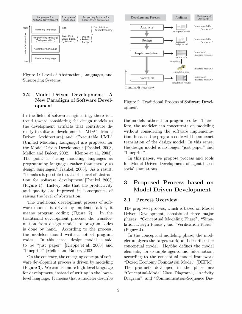
Figure 1: Level of Abstraction, Languages, andSupporting Systems
2.2 Model Driven Development: ANew Paradigm of Software Devel-opment
In the field of software engineering, there is atrend toward considering the design models asthe development artifacts that contribute di-rectly to software development. “MDA” (ModelDriven Architecture) and “Executable UML”(Unified Modeling Language) are proposed forthe Model Driven Development [Frankel, 2003,Mellor and Balcer, 2002, Kleppe et al., 2003].The point is “using modeling languages asprogramming languages rather than merely asdesign languages.”[Frankel, 2003]. As a result,“It makes it possible to raise the level of abstrac-tion for software development”[Frankel, 2003](Figure 1). History tells that the productivityand quality are improved in consequence ofraising the level of abstraction.
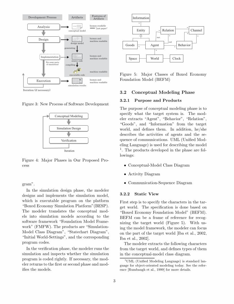
The traditional development process of soft-ware models is driven by implementation, itmeans program coding (Figure 2). In thetraditional development process, the transfor-mation from design models to program codesis done by hand. According to the process,the modeler should write a lot of programcodes. In this sense, design model is saidto be “just paper” [Kleppe et al., 2003] and“blueprint” [Mellor and Balcer, 2002].
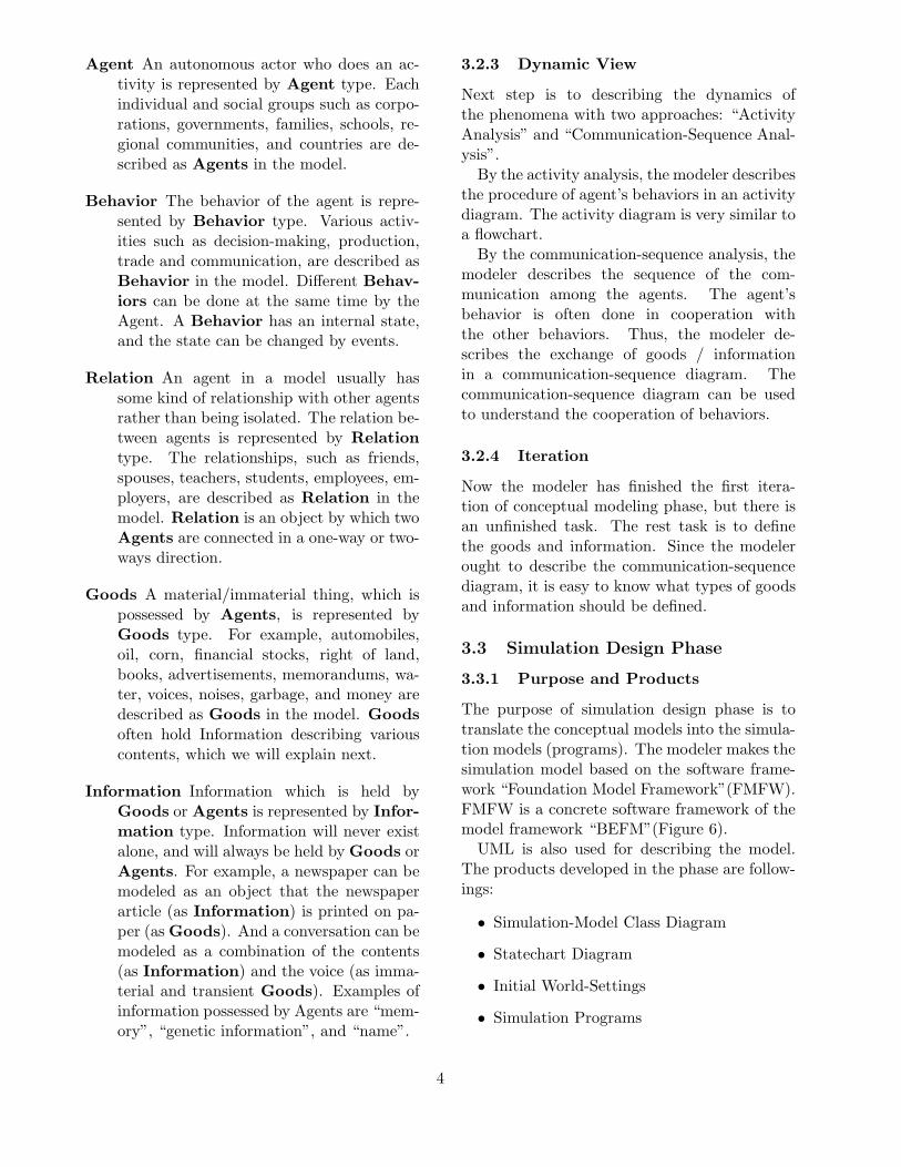
On the contrary, the emerging concept of soft-ware development process is driven by modeling(Figure 3). We can use more high-level languagefor development, instead of writing in the lower-level language. It means that a modeler describe
Analysis
Design
Implementation
Execution
Development Process Artifacts Features ofArtifacts
Iteration (if necessary)
human and machine readable
human and machine readable
machine readable
DecideMoveByTitForTatBehavior
DecideMoveByTitFor2TatBehavior
DecideMoveByFriedmanBehavior
Behavior
conceptual model
design model
public class SayHelloBehavior extends AbstractSayHelloBehavior {
protected void initialize() { // TODO Auto-generated method stub } protected void terminate() { // TODO Auto-generated method stub } protected void sayHelloAction() { MessageInformation message = new MessageInformation("Hello"); this.sendInformation(TutorialModel.RELATIONTYPE_Friends, TutorialModel.BEHAVIORTYPE_ReceiveBehavior, message); } protected void receiveMessageAction() { Information receivedInformation = getReceivedInformation(); }}
source code
simulation results
Pit, Ait, Uit, x, s, Rit, Qit, Sit, Mit
14.3, 90.2, 25.0, 2, 0.2, 3.2, 55.4 ,95.9, 28.7
26.1, 87.5, 26.8, 0, 0.2, 0.0, 38.2, 12.0, 34.1
25.3, 88.9, 25.0, 2, 0.4, 3.9, 53.7 ,93.1, 28.7
38.2, 12.0, 34.1, 2, 0.5, 5.7, 63.9, 86.2, 26.9
57.1, 98.9, 32.3, 0, 0.5, 0.0, 53.7 ,93.1, 28.7
55.4 ,95.9, 28.7, 0, 0.5, 0.0, 47.5, 88.8, 26.1
53.7 ,93.1, 28.7, 0, 0.5, 0.0, 50.5, 87.6, 28.7
52.1, 90.3, 28.7, 0, 0.5, 0.0, 63.9, 86.2, 26.9
50.5, 87.6, 28.7, 0, 0.5, 0.0, 26.1, 87.5, 26.8
49.0, 84.9, 28.7, 0, 0.5, 0.0, 14.3, 90.2, 25.0
47.5, 88.8, 26.1, 1, 0.7, 6.4, 47.5, 88.8, 26.1
name="taro"ID=2
amount=1
executable code
compiling
human readable "just paper"
human readable "just paper"
Figure 2: Traditional Process of Software Devel-opment
the models rather than program codes. There-fore, the modeler can concentrate on modelingwithout considering the software implementa-tion, because the program code will be an exacttranslation of the design model. In this sense,the design model is no longer “just paper” and“blueprint”.
In this paper, we propose process and toolsfor Model Driven Development of agent-basedsocial simulations.
3 Proposed Process based on
Model Driven Development
3.1 Process Overview
The proposed process, which is based on ModelDriven Development, consists of three majorphases: “Conceptual Modeling Phase”, “Simu-lation Design Phase”, and “Verification Phase”(Figure 4).
In the conceptual modeling phase, the mod-eler analyzes the target world and describes theconceptual model. He/She defines the modelelements, for example agents and information,according to the conceptual model framework“Boxed Economy Foundation Model” (BEFM).The products developed in the phase are“Conceptual-Model Class Diagram”, “ActivityDiagram”, and “Communication-Sequence Dia-
2
Analysis
Design
Implementation
Execution
Development Process Artifacts Features ofArtifacts
Iteration (if necessary)
human and machine readable
human and machine readable
human and machine readable
machine readable
DecideMoveByTitForTatBehavior
DecideMoveByTitFor2TatBehavior
DecideMoveByFriedmanBehavior
Behavior
conceptual model
design model
public class SayHelloBehavior extends AbstractSayHelloBehavior {
protected void initialize() { // TODO Auto-generated method stub } protected void terminate() { // TODO Auto-generated method stub } protected void sayHelloAction() { MessageInformation message = new MessageInformation("Hello"); this.sendInformation(TutorialModel.RELATIONTYPE_Friends, TutorialModel.BEHAVIORTYPE_ReceiveBehavior, message); } protected void receiveMessageAction() { Information receivedInformation = getReceivedInformation(); }}
source code
simulation results
Pit, Ait, Uit, x, s, Rit, Qit, Sit, Mit
14.3, 90.2, 25.0, 2, 0.2, 3.2, 55.4 ,95.9, 28.7
26.1, 87.5, 26.8, 0, 0.2, 0.0, 38.2, 12.0, 34.1
25.3, 88.9, 25.0, 2, 0.4, 3.9, 53.7 ,93.1, 28.7
38.2, 12.0, 34.1, 2, 0.5, 5.7, 63.9, 86.2, 26.9
57.1, 98.9, 32.3, 0, 0.5, 0.0, 53.7 ,93.1, 28.7
55.4 ,95.9, 28.7, 0, 0.5, 0.0, 47.5, 88.8, 26.1
53.7 ,93.1, 28.7, 0, 0.5, 0.0, 50.5, 87.6, 28.7
52.1, 90.3, 28.7, 0, 0.5, 0.0, 63.9, 86.2, 26.9
50.5, 87.6, 28.7, 0, 0.5, 0.0, 26.1, 87.5, 26.8
49.0, 84.9, 28.7, 0, 0.5, 0.0, 14.3, 90.2, 25.0
47.5, 88.8, 26.1, 1, 0.7, 6.4, 47.5, 88.8, 26.1
name="taro"ID=2
amount=1
executable code
compiling
generating
human readable "just paper"
(for some parts of simulation)
Figure 3: New Process of Software Development
Conceptual Modeling
Simulation Design
Verification
Iteration
Figure 4: Major Phases in Our Proposed Pro-cess
gram”.In the simulation design phase, the modeler
designs and implements the simulation model,which is executable program on the platform“Boxed Economy Simulation Platform”(BESP).The modeler translates the conceptual mod-els into simulation models according to thesoftware framework “Foundation Model Frame-work” (FMFW). The products are “Simulation-Model Class Diagram”, “Statechart Diagram”,“Initial World-Settings”, and the correspondingprogram codes.
In the verification phase, the modeler runs thesimulation and inspects whether the simulationprogram is coded rightly. If necessary, the mod-eler returns to the first or second phase and mod-ifies the models.
Space World
Information
Behavior
Clock
Goods
*
**
*
*
* RelationEntity
Agent
Channel
* *
*
end
start
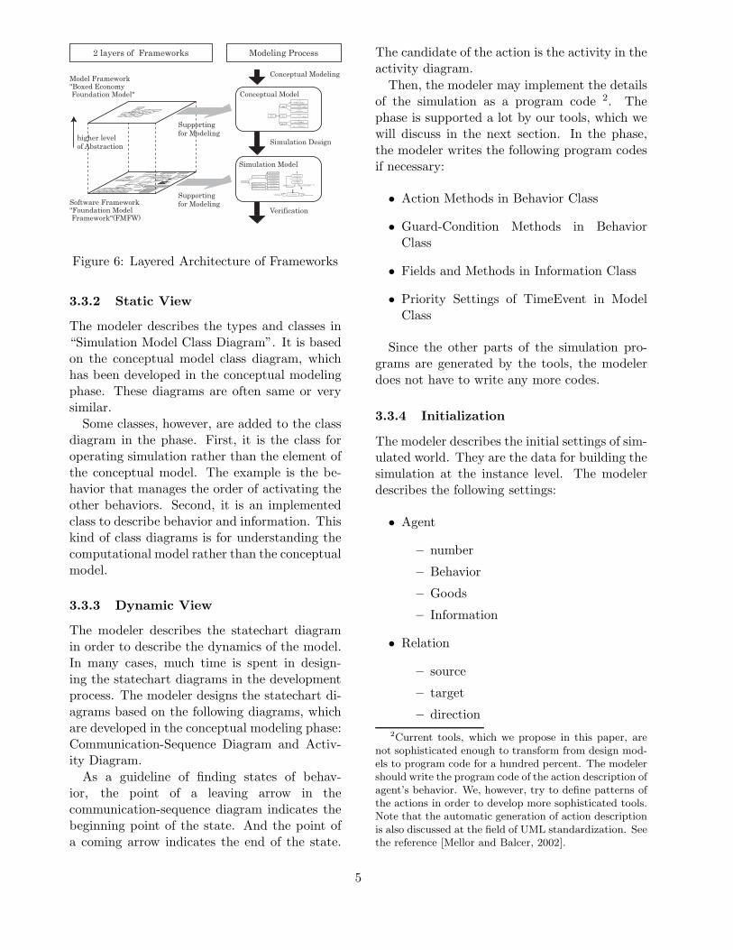
Figure 5: Major Classes of Boxed EconomyFoundation Model (BEFM)
3.2 Conceptual Modeling Phase
3.2.1 Purpose and Products
The purpose of conceptual modeling phase is tospecify what the target system is. The mod-eler extracts “Agent”, “Behavior”, “Relation”,“Goods”, and “Information” from the targetworld, and defines them. In addition, he/shedescribes the activities of agents and the se-quence of communications. UML (Unified Mod-eling Language) is used for describing the model1. The products developed in the phase are fol-lowings:
• Conceptual-Model Class Diagram
• Activity Diagram
• Communication-Sequence Diagram
3.2.2 Static View
First step is to specify the characters in the tar-get world. The specification is done based on“Boxed Economy Foundation Model” (BEFM).BEFM can be a frame of reference for recog-nizing the target world (Figure 5). With us-ing the model framework, the modeler can focuson the part of the target world [Iba et al., 2002,Iba et al., 2002].
The modeler extracts the following charactersfrom the target world, and defines types of themin the conceptual-model class diagram.
1UML (Unified Modeling Language) is standard lan-guage for object-oriented modeling today. See the refer-ence [Rumbaugh et al., 1999] for more details.
3
Agent An autonomous actor who does an ac-tivity is represented by Agent type. Eachindividual and social groups such as corpo-rations, governments, families, schools, re-gional communities, and countries are de-scribed as Agents in the model.
Behavior The behavior of the agent is repre-sented by Behavior type. Various activ-ities such as decision-making, production,trade and communication, are described asBehavior in the model. Different Behav-iors can be done at the same time by theAgent. A Behavior has an internal state,and the state can be changed by events.
Relation An agent in a model usually hassome kind of relationship with other agentsrather than being isolated. The relation be-tween agents is represented by Relationtype. The relationships, such as friends,spouses, teachers, students, employees, em-ployers, are described as Relation in themodel. Relation is an object by which twoAgents are connected in a one-way or two-ways direction.
Goods A material/immaterial thing, which ispossessed by Agents, is represented byGoods type. For example, automobiles,oil, corn, financial stocks, right of land,books, advertisements, memorandums, wa-ter, voices, noises, garbage, and money aredescribed as Goods in the model. Goodsoften hold Information describing variouscontents, which we will explain next.
Information Information which is held byGoods or Agents is represented by Infor-mation type. Information will never existalone, and will always be held by Goods orAgents. For example, a newspaper can bemodeled as an object that the newspaperarticle (as Information) is printed on pa-per (as Goods). And a conversation can bemodeled as a combination of the contents(as Information) and the voice (as imma-terial and transient Goods). Examples ofinformation possessed by Agents are “mem-ory”, “genetic information”, and “name”.
3.2.3 Dynamic View
Next step is to describing the dynamics ofthe phenomena with two approaches: “ActivityAnalysis” and “Communication-Sequence Anal-ysis”.
By the activity analysis, the modeler describesthe procedure of agent’s behaviors in an activitydiagram. The activity diagram is very similar toa flowchart.
By the communication-sequence analysis, themodeler describes the sequence of the com-munication among the agents. The agent’sbehavior is often done in cooperation withthe other behaviors. Thus, the modeler de-scribes the exchange of goods / informationin a communication-sequence diagram. Thecommunication-sequence diagram can be usedto understand the cooperation of behaviors.
3.2.4 Iteration
Now the modeler has finished the first itera-tion of conceptual modeling phase, but there isan unfinished task. The rest task is to definethe goods and information. Since the modelerought to describe the communication-sequencediagram, it is easy to know what types of goodsand information should be defined.
3.3 Simulation Design Phase
3.3.1 Purpose and Products
The purpose of simulation design phase is totranslate the conceptual models into the simula-tion models (programs). The modeler makes thesimulation model based on the software frame-work “Foundation Model Framework”(FMFW).FMFW is a concrete software framework of themodel framework “BEFM”(Figure 6).
UML is also used for describing the model.The products developed in the phase are follow-ings:
• Simulation-Model Class Diagram
• Statechart Diagram
• Initial World-Settings
• Simulation Programs
4
RelationType
Relation
GoodsType
Goods
InformationTypeBehaviorTypeAgentType
Agent
Type
Behavior<<abstract>> Information<<interface>>
parents**
children<<abstract>>
AGENT_Environment AGENT_AgentCellSpace- xCellNum : int
- yCellNum : int- is Loop : Boolean
+ CellSpace ( )+ moveAgent ( )
+ addAgent ( )+ removeAgent ( )
+ getCell ( )+ getAgents ( )
+ getCellList ( )+ getCell ( )
+ getAgentCount ( )+ getXCellNum ( )
+ get YCellNum ( )- getAbsoluteCellRound ( )
- getAbsoluteCellNotRound ( )- xRangeValid ( )
- yRangeValid ( )- xyRangeValid ( )
Cell- x : int
- y : int
SSSearchResultInformation SSSearchRequestInformationSSFieldInformation
+ getSugar ( )
SSCellInformation- sugar : int
**
*ScopeScope
MooreScopeMooreScope+ getNeighborCells+ getNeighborCells
- range : int- range : int
<<GoodsType>>Format2_VCR<<GoodsType>>Format1_VCR
<<GoodsType>>VCR
AgentTypeAGENT_Environment SupplySugarBehavior
MoveAndEatBehaviorAGENT_SSAgent<<instanceOf>>
RelationType
RELATION_DiffusionControllerRELATION_SurveyTarget
RELATION_FriendRELATION_InformationSupplier
RELATION_Seller
<<instanceOf>>
Model Framework"Boxed Economy Foundation Model"
Software Framework"Foundation Model Framework"(FMFW)
Space World
Information
Behavior
Clock
Goods
*
* *
*
** RelationEntity
Agent
Channel
* **
endstart
higher levelof Abstraction
Conceptual Model<<Type>>
<<Type>><<Type>>
Agent
<<Type>>
<<Type>>
<<Type>>
<<Type>>
<<Type>>
<<Type>>
<<Type>>
Simulation Model
AgentType
RecognizeVCRNeedsBehavior
ReplyFormatBehavior
PurchaseVCRBehavior
UseVCRBehavior
AGENT_Consumer
AGENT_DiffusionControlFunction PermitVCRNeedsBehavior
AGENT_Shop SellVCRBehavior
SurveyBehaviorAGENT_SurveyCompany
<<instanceOf>>
ChannelEvent[ , ] / PurchaseVCRBehavior
TimeEvent /
ChannelEvent[ , ]
ChannelEvent [ ]
/
TimeEvent
/ VCR
Supportingfor Modeling
Supportingfor Modeling
Conceptual Modeling
Simulation Design
Verification
2 layers of Frameworks Modeling Process
Figure 6: Layered Architecture of Frameworks
3.3.2 Static View
The modeler describes the types and classes in“Simulation Model Class Diagram”. It is basedon the conceptual model class diagram, whichhas been developed in the conceptual modelingphase. These diagrams are often same or verysimilar.
Some classes, however, are added to the classdiagram in the phase. First, it is the class foroperating simulation rather than the element ofthe conceptual model. The example is the be-havior that manages the order of activating theother behaviors. Second, it is an implementedclass to describe behavior and information. Thiskind of class diagrams is for understanding thecomputational model rather than the conceptualmodel.
3.3.3 Dynamic View
The modeler describes the statechart diagramin order to describe the dynamics of the model.In many cases, much time is spent in design-ing the statechart diagrams in the developmentprocess. The modeler designs the statechart di-agrams based on the following diagrams, whichare developed in the conceptual modeling phase:Communication-Sequence Diagram and Activ-ity Diagram.
As a guideline of finding states of behav-ior, the point of a leaving arrow in thecommunication-sequence diagram indicates thebeginning point of the state. And the point ofa coming arrow indicates the end of the state.
The candidate of the action is the activity in theactivity diagram.
Then, the modeler may implement the detailsof the simulation as a program code 2. Thephase is supported a lot by our tools, which wewill discuss in the next section. In the phase,the modeler writes the following program codesif necessary:
• Action Methods in Behavior Class
• Guard-Condition Methods in BehaviorClass
• Fields and Methods in Information Class
• Priority Settings of TimeEvent in ModelClass
Since the other parts of the simulation pro-grams are generated by the tools, the modelerdoes not have to write any more codes.
3.3.4 Initialization
The modeler describes the initial settings of sim-ulated world. They are the data for building thesimulation at the instance level. The modelerdescribes the following settings:
• Agent
– number
– Behavior
– Goods
– Information
• Relation
– source
– target
– direction2Current tools, which we propose in this paper, are
not sophisticated enough to transform from design mod-els to program code for a hundred percent. The modelershould write the program code of the action description ofagent’s behavior. We, however, try to define patterns ofthe actions in order to develop more sophisticated tools.Note that the automatic generation of action descriptionis also discussed at the field of UML standardization. Seethe reference [Mellor and Balcer, 2002].
5
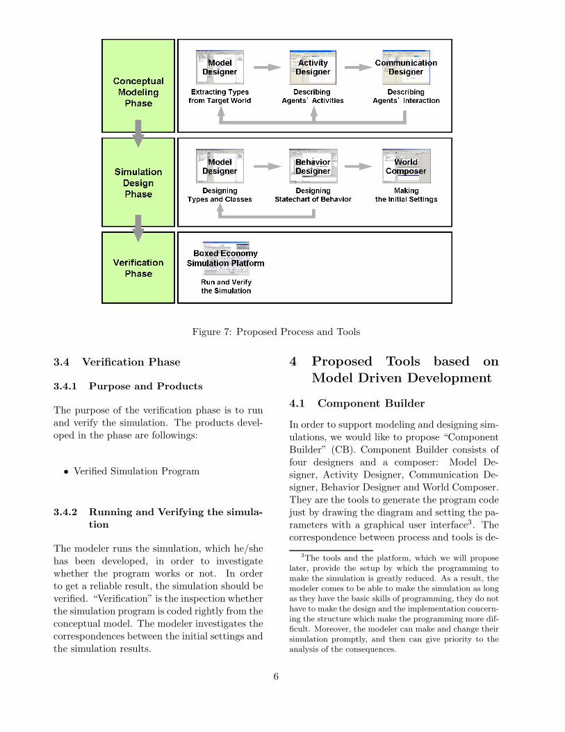
Figure 7: Proposed Process and Tools
3.4 Verification Phase
3.4.1 Purpose and Products
The purpose of the verification phase is to runand verify the simulation. The products devel-oped in the phase are followings:
• Verified Simulation Program
3.4.2 Running and Verifying the simula-tion
The modeler runs the simulation, which he/shehas been developed, in order to investigatewhether the program works or not. In orderto get a reliable result, the simulation should beverified. “Verification” is the inspection whetherthe simulation program is coded rightly from theconceptual model. The modeler investigates thecorrespondences between the initial settings andthe simulation results.
4 Proposed Tools based on
Model Driven Development
4.1 Component Builder
In order to support modeling and designing sim-ulations, we would like to propose “ComponentBuilder” (CB). Component Builder consists offour designers and a composer: Model De-signer, Activity Designer, Communication De-signer, Behavior Designer and World Composer.They are the tools to generate the program codejust by drawing the diagram and setting the pa-rameters with a graphical user interface3. Thecorrespondence between process and tools is de-
3The tools and the platform, which we will proposelater, provide the setup by which the programming tomake the simulation is greatly reduced. As a result, themodeler comes to be able to make the simulation as longas they have the basic skills of programming, they do nothave to make the design and the implementation concern-ing the structure which make the programming more dif-ficult. Moreover, the modeler can make and change theirsimulation promptly, and then can give priority to theanalysis of the consequences.
6
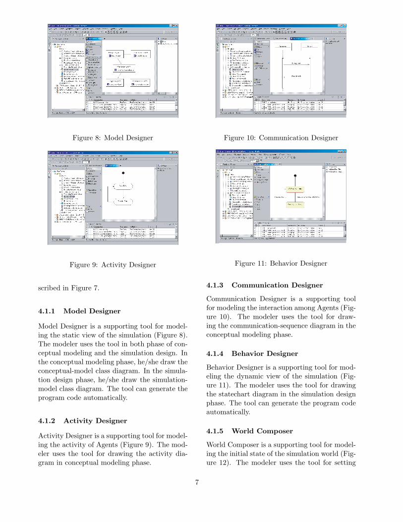
Figure 8: Model Designer
Figure 9: Activity Designer
scribed in Figure 7.
4.1.1 Model Designer
Model Designer is a supporting tool for model-ing the static view of the simulation (Figure 8).The modeler uses the tool in both phase of con-ceptual modeling and the simulation design. Inthe conceptual modeling phase, he/she draw theconceptual-model class diagram. In the simula-tion design phase, he/she draw the simulation-model class diagram. The tool can generate theprogram code automatically.
4.1.2 Activity Designer
Activity Designer is a supporting tool for model-ing the activity of Agents (Figure 9). The mod-eler uses the tool for drawing the activity dia-gram in conceptual modeling phase.
Figure 10: Communication Designer
Figure 11: Behavior Designer
4.1.3 Communication Designer
Communication Designer is a supporting toolfor modeling the interaction among Agents (Fig-ure 10). The modeler uses the tool for draw-ing the communication-sequence diagram in theconceptual modeling phase.
4.1.4 Behavior Designer
Behavior Designer is a supporting tool for mod-eling the dynamic view of the simulation (Fig-ure 11). The modeler uses the tool for drawingthe statechart diagram in the simulation designphase. The tool can generate the program codeautomatically.
4.1.5 World Composer
World Composer is a supporting tool for model-ing the initial state of the simulation world (Fig-ure 12). The modeler uses the tool for setting
7
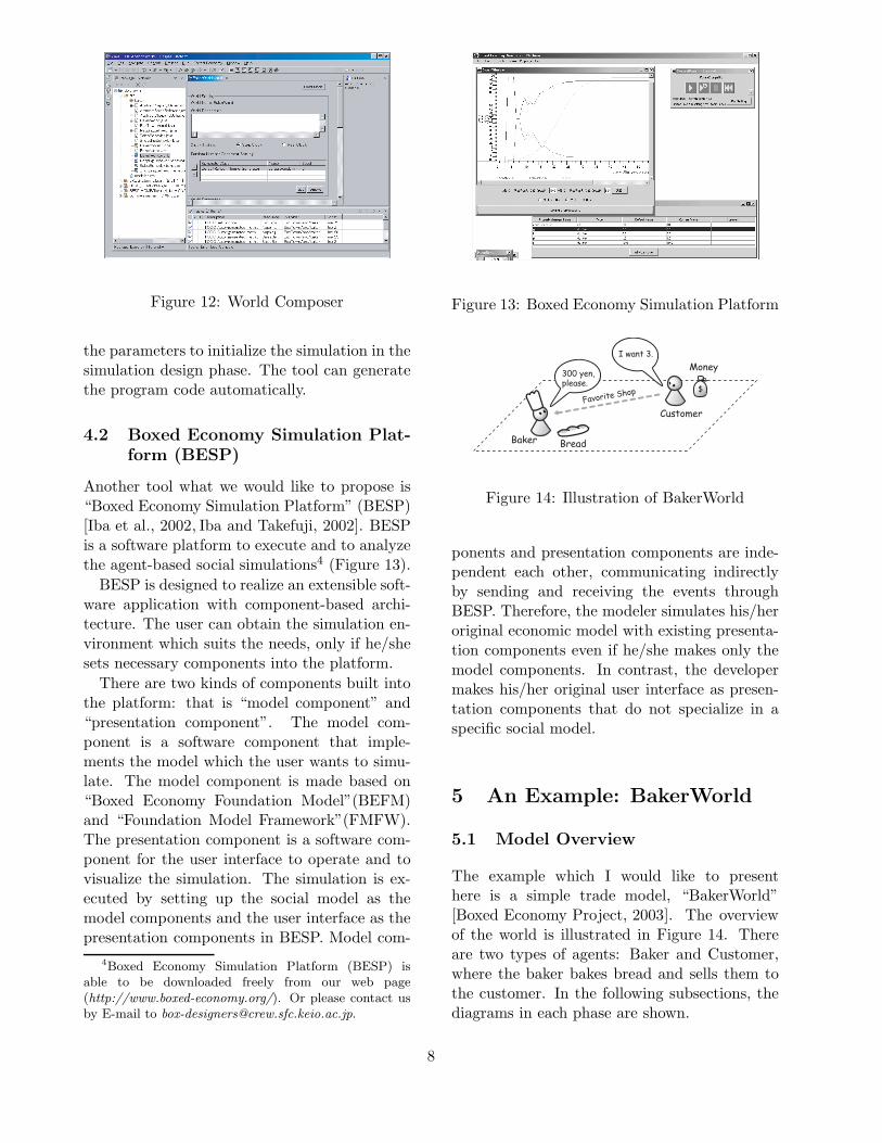
Figure 12: World Composer
the parameters to initialize the simulation in thesimulation design phase. The tool can generatethe program code automatically.
4.2 Boxed Economy Simulation Plat-form (BESP)
Another tool what we would like to propose is“Boxed Economy Simulation Platform” (BESP)[Iba et al., 2002, Iba and Takefuji, 2002]. BESPis a software platform to execute and to analyzethe agent-based social simulations4 (Figure 13).
BESP is designed to realize an extensible soft-ware application with component-based archi-tecture. The user can obtain the simulation en-vironment which suits the needs, only if he/shesets necessary components into the platform.
There are two kinds of components built intothe platform: that is “model component” and“presentation component”. The model com-ponent is a software component that imple-ments the model which the user wants to simu-late. The model component is made based on“Boxed Economy Foundation Model”(BEFM)and “Foundation Model Framework”(FMFW).The presentation component is a software com-ponent for the user interface to operate and tovisualize the simulation. The simulation is ex-ecuted by setting up the social model as themodel components and the user interface as thepresentation components in BESP. Model com-
4Boxed Economy Simulation Platform (BESP) isable to be downloaded freely from our web page(http://www.boxed-economy.org/). Or please contact usby E-mail to [email protected].
Figure 13: Boxed Economy Simulation Platform
Baker
Customer
Bread
Money
Favorite Shop
300 yen,please.
I want 3.
$
Figure 14: Illustration of BakerWorld
ponents and presentation components are inde-pendent each other, communicating indirectlyby sending and receiving the events throughBESP. Therefore, the modeler simulates his/heroriginal economic model with existing presenta-tion components even if he/she makes only themodel components. In contrast, the developermakes his/her original user interface as presen-tation components that do not specialize in aspecific social model.
5 An Example: BakerWorld
5.1 Model Overview
The example which I would like to presenthere is a simple trade model, “BakerWorld”[Boxed Economy Project, 2003]. The overviewof the world is illustrated in Figure 14. Thereare two types of agents: Baker and Customer,where the baker bakes bread and sells them tothe customer. In the following subsections, thediagrams in each phase are shown.
8
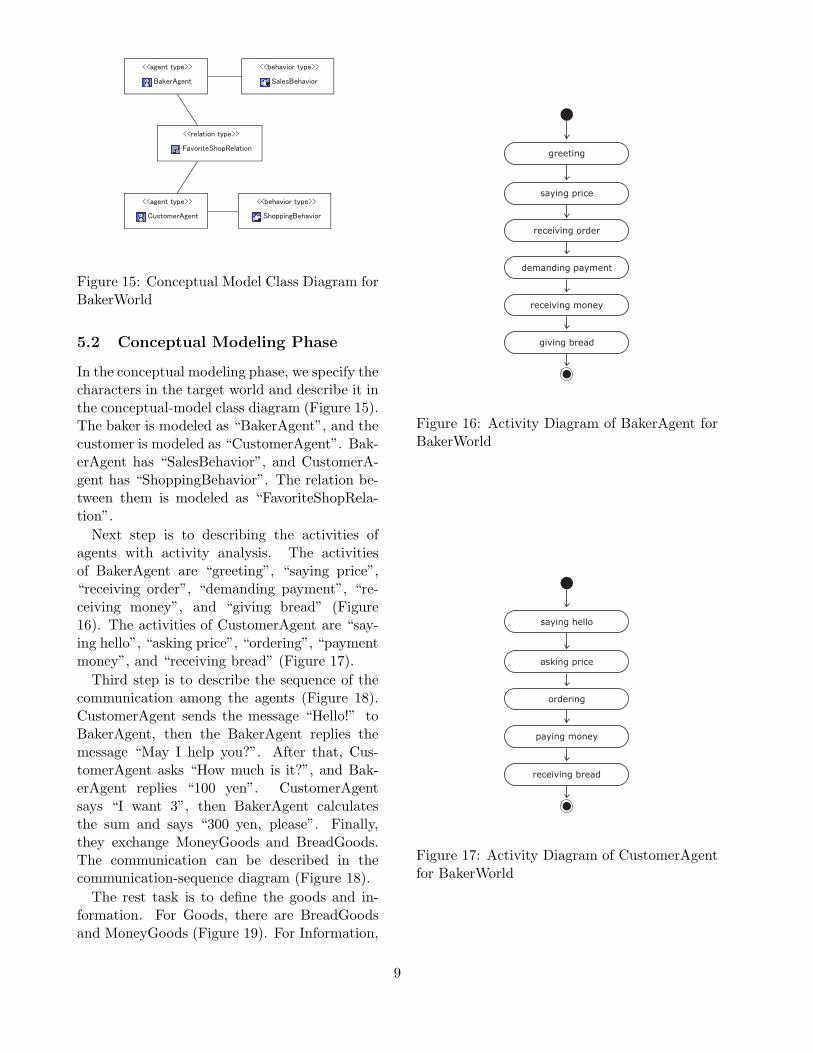
Figure 15: Conceptual Model Class Diagram forBakerWorld
5.2 Conceptual Modeling Phase
In the conceptual modeling phase, we specify thecharacters in the target world and describe it inthe conceptual-model class diagram (Figure 15).The baker is modeled as “BakerAgent”, and thecustomer is modeled as “CustomerAgent”. Bak-erAgent has “SalesBehavior”, and CustomerA-gent has “ShoppingBehavior”. The relation be-tween them is modeled as “FavoriteShopRela-tion”.
Next step is to describing the activities ofagents with activity analysis. The activitiesof BakerAgent are “greeting”, “saying price”,“receiving order”, “demanding payment”, “re-ceiving money”, and “giving bread” (Figure16). The activities of CustomerAgent are “say-ing hello”, “asking price”, “ordering”, “paymentmoney”, and “receiving bread” (Figure 17).
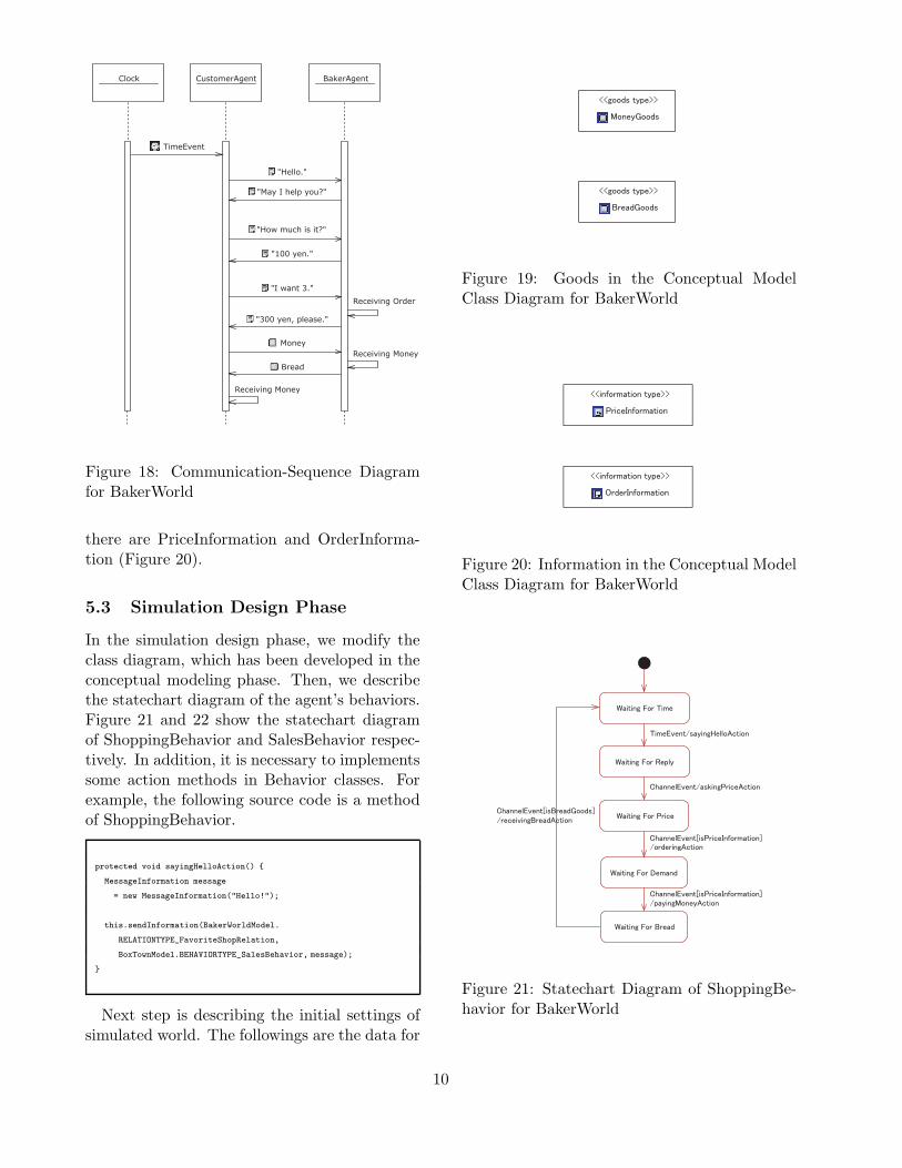
Third step is to describe the sequence of thecommunication among the agents (Figure 18).CustomerAgent sends the message “Hello!” toBakerAgent, then the BakerAgent replies themessage “May I help you?”. After that, Cus-tomerAgent asks “How much is it?”, and Bak-erAgent replies “100 yen”. CustomerAgentsays “I want 3”, then BakerAgent calculatesthe sum and says “300 yen, please”. Finally,they exchange MoneyGoods and BreadGoods.The communication can be described in thecommunication-sequence diagram (Figure 18).
The rest task is to define the goods and in-formation. For Goods, there are BreadGoodsand MoneyGoods (Figure 19). For Information,
greeting
saying price
receiving order
demanding payment
receiving money
giving bread
Figure 16: Activity Diagram of BakerAgent forBakerWorld
saying hello
asking price
ordering
paying money
receiving bread
Figure 17: Activity Diagram of CustomerAgentfor BakerWorld
9
"Hello."
"100 yen."
"I want 3."
"300 yen, please."
Receiving Order
BakerAgent
TimeEvent
CustomerAgentClock
Bread
Money
Receiving Money
Receiving Money
"May I help you?"
"How much is it?"
Figure 18: Communication-Sequence Diagramfor BakerWorld
there are PriceInformation and OrderInforma-tion (Figure 20).
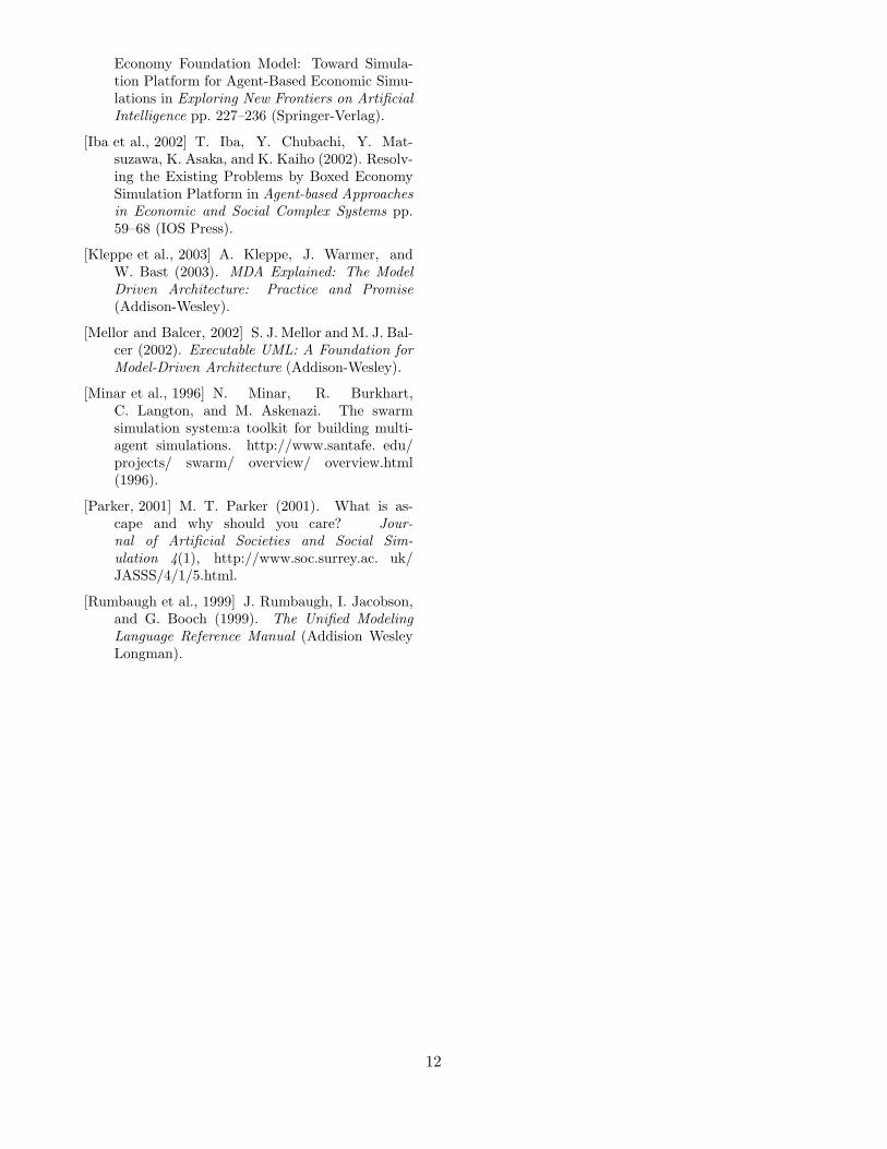
5.3 Simulation Design Phase
In the simulation design phase, we modify theclass diagram, which has been developed in theconceptual modeling phase. Then, we describethe statechart diagram of the agent’s behaviors.Figure 21 and 22 show the statechart diagramof ShoppingBehavior and SalesBehavior respec-tively. In addition, it is necessary to implementssome action methods in Behavior classes. Forexample, the following source code is a methodof ShoppingBehavior.
protected void sayingHelloAction() {
MessageInformation message
= new MessageInformation("Hello!");
this.sendInformation(BakerWorldModel.
RELATIONTYPE_FavoriteShopRelation,
BoxTownModel.BEHAVIORTYPE_SalesBehavior, message);
}
Next step is describing the initial settings ofsimulated world. The followings are the data for
Figure 19: Goods in the Conceptual ModelClass Diagram for BakerWorld
Figure 20: Information in the Conceptual ModelClass Diagram for BakerWorld
Figure 21: Statechart Diagram of ShoppingBe-havior for BakerWorld
10
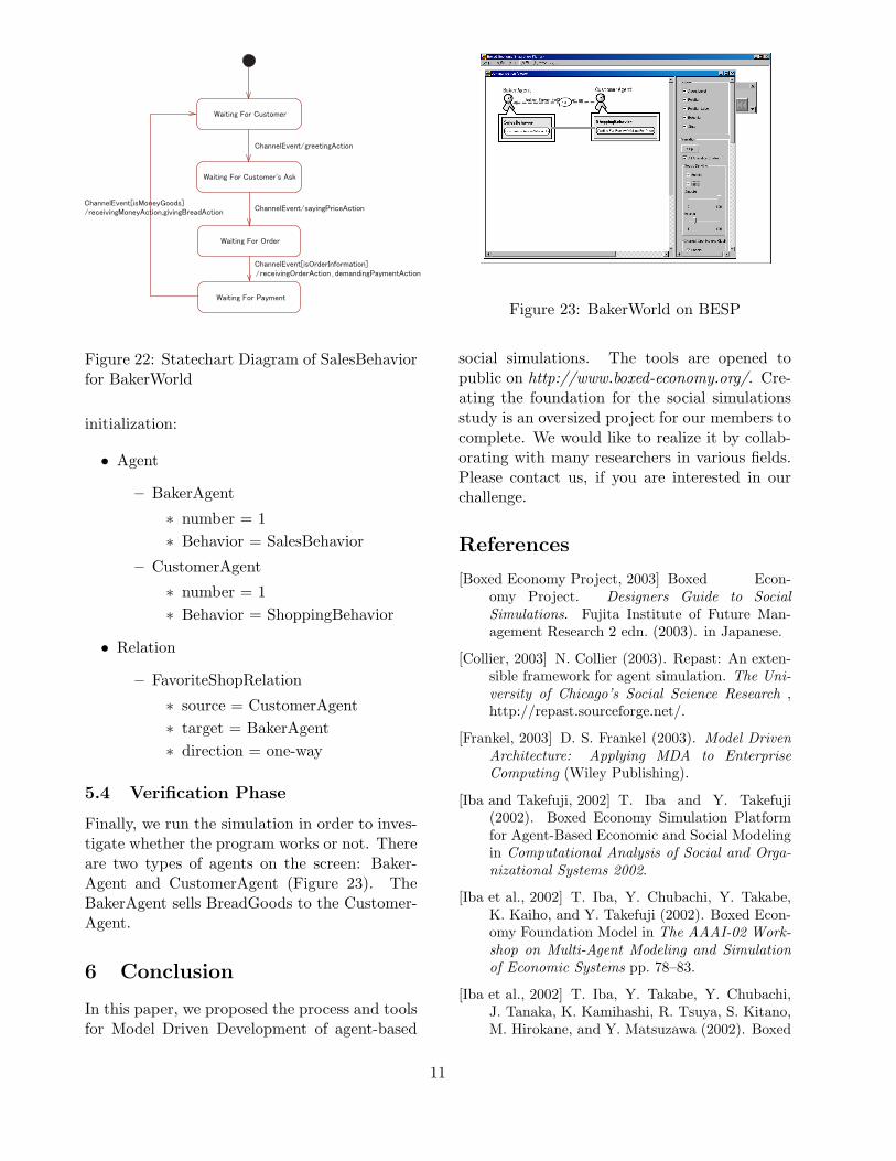
Figure 22: Statechart Diagram of SalesBehaviorfor BakerWorld
initialization:
• Agent
– BakerAgent
∗ number = 1∗ Behavior = SalesBehavior
– CustomerAgent
∗ number = 1∗ Behavior = ShoppingBehavior
• Relation
– FavoriteShopRelation
∗ source = CustomerAgent∗ target = BakerAgent∗ direction = one-way
5.4 Verification Phase
Finally, we run the simulation in order to inves-tigate whether the program works or not. Thereare two types of agents on the screen: Baker-Agent and CustomerAgent (Figure 23). TheBakerAgent sells BreadGoods to the Customer-Agent.
6 Conclusion
In this paper, we proposed the process and toolsfor Model Driven Development of agent-based
Figure 23: BakerWorld on BESP
social simulations. The tools are opened topublic on http://www.boxed-economy.org/. Cre-ating the foundation for the social simulationsstudy is an oversized project for our members tocomplete. We would like to realize it by collab-orating with many researchers in various fields.Please contact us, if you are interested in ourchallenge.
References
[Boxed Economy Project, 2003] Boxed Econ-omy Project. Designers Guide to SocialSimulations. Fujita Institute of Future Man-agement Research 2 edn. (2003). in Japanese.
[Collier, 2003] N. Collier (2003). Repast: An exten-sible framework for agent simulation. The Uni-versity of Chicago’s Social Science Research ,http://repast.sourceforge.net/.
[Frankel, 2003] D. S. Frankel (2003). Model DrivenArchitecture: Applying MDA to EnterpriseComputing (Wiley Publishing).
[Iba and Takefuji, 2002] T. Iba and Y. Takefuji(2002). Boxed Economy Simulation Platformfor Agent-Based Economic and Social Modelingin Computational Analysis of Social and Orga-nizational Systems 2002.
[Iba et al., 2002] T. Iba, Y. Chubachi, Y. Takabe,K. Kaiho, and Y. Takefuji (2002). Boxed Econ-omy Foundation Model in The AAAI-02 Work-shop on Multi-Agent Modeling and Simulationof Economic Systems pp. 78–83.
[Iba et al., 2002] T. Iba, Y. Takabe, Y. Chubachi,J. Tanaka, K. Kamihashi, R. Tsuya, S. Kitano,M. Hirokane, and Y. Matsuzawa (2002). Boxed
11
Economy Foundation Model: Toward Simula-tion Platform for Agent-Based Economic Simu-lations in Exploring New Frontiers on ArtificialIntelligence pp. 227–236 (Springer-Verlag).
[Iba et al., 2002] T. Iba, Y. Chubachi, Y. Mat-suzawa, K. Asaka, and K. Kaiho (2002). Resolv-ing the Existing Problems by Boxed EconomySimulation Platform in Agent-based Approachesin Economic and Social Complex Systems pp.59–68 (IOS Press).
[Kleppe et al., 2003] A. Kleppe, J. Warmer, andW. Bast (2003). MDA Explained: The ModelDriven Architecture: Practice and Promise(Addison-Wesley).
[Mellor and Balcer, 2002] S. J. Mellor and M. J. Bal-cer (2002). Executable UML: A Foundation forModel-Driven Architecture (Addison-Wesley).
[Minar et al., 1996] N. Minar, R. Burkhart,C. Langton, and M. Askenazi. The swarmsimulation system:a toolkit for building multi-agent simulations. http://www.santafe. edu/projects/ swarm/ overview/ overview.html(1996).
[Parker, 2001] M. T. Parker (2001). What is as-cape and why should you care? Jour-nal of Artificial Societies and Social Sim-ulation 4(1), http://www.soc.surrey.ac. uk/JASSS/4/1/5.html.
[Rumbaugh et al., 1999] J. Rumbaugh, I. Jacobson,and G. Booch (1999). The Unified ModelingLanguage Reference Manual (Addision WesleyLongman).
12