Embed Size (px)
Citation preview

nVent.com | 1RAYCHEM-DG-H58139-RaySolMIFreFrostHeat-EN-1909
FREEZER FROST HEAVE PREVENTION – RAYSOL AND MI HEATING CABLE SYSTEM
This step-by-step design guide provides the tools necessary to design an nVent RAYCHEM RaySol self-regulating heating cable system or an nVent RAYCHEM Mineral Insulated heating cable system for freezer frost heave prevention. For other applications or for design assistance, contact your nVent representative or call (800) 545-6258. Also, visit our website at nVentthermal.com.
CONTENTSINTRODUCTION ...................................................................................... 2How to Use this Guide ........................................................................................................... 2Safety Guidelines .................................................................................................................... 2Warranty ................................................................................................................................... 3SYSTEM OVERVIEW ............................................................................... 3Typical System ........................................................................................................................ 4Self-Regulating Heating Cable Construction .................................................................... 6MI Heating Cable Construction ........................................................................................... 7Approvals ................................................................................................................................. 8FREEZER FROST HEAVE PREVENTION DESIGN ..................................... 8Design Assumptions ............................................................................................................. 8Design Step by Step RaySol and MI Heating Cables in Conduit .................................. 9
Step 1 Determine the freezer configuration ............................................................. 10Step 2 Select the heating cable .................................................................................. 11Step 3 Determine the heating cable conduit spacing and freezer load ............. 14Step 4 Determine the heating cable layout and length .......................................... 15Step 5 Determine the electrical parameters ............................................................22Step 6 Select the connection kits and accessories ...............................................24Step 7 Select the control system ...............................................................................25Step 8 Select the power distribution ........................................................................27Step 9 Complete the Bill of Materials ........................................................................29
Design Step by Step MI Heating Cables Directly Embedded ......................................30Step 1 Determine the freezer configuration .............................................................31Step 2 Determine heat loss and freezer load ...........................................................32Step 3 Select the heating cable, layout and length.................................................34Step 4 Determine the heating cable spacing ........................................................... 41Step 5 Determine the electrical parameters ............................................................ 41Step 6 Select the accessories.....................................................................................43Step 7 Select the control system ...............................................................................44Step 8 Select the power distribution ........................................................................45Step 9 Complete the Bill of Materials ........................................................................48
RAYSOL AND MI HEATING CABLE IN CONDUIT FREEZER FROST HEAVE PREVENTION DESIGN WORKSHEET ..................................................... 49
MI CABLES DIRECTLY EMBEDDED FREEZER FROST HEAVE PREVENTION DESIGN WORKSHEET ..................................................... 54

nVent.com | 2RAYCHEM-DG-H58139-RaySolMIFreFrostHeat-EN-1909
INTRODUCTION
nVent offers two different heating cable technologies for freezer frost heave prevention: RaySol self-regulating heating cable system and MI heating cable system. Both RaySol and MI heating cables can be installed in conduit. Only MI heating cables can be embedded directly in the subfloor (concrete, sand, or compacted fill).
If your application conditions are different, or if you have any questions, contact your nVent representative or call (800) 545-6258.
How to Use this Guide
This design guide presents nVent recommendations for designing freezer frost heave prevention systems. It provides design and performance data, electrical sizing information, and heating cable layout suggestions. Following these recommendations will result in a reliable, energy-efficient system.
Follow the design steps in the respective “Design” sections and use the appropriate “RaySol and MI Heating Cable in Conduit Freezer Frost Heave Prevention Design Worksheet” on page 49 and “MI Cables Directly Embedded Freezer Frost Heave Prevention Design Worksheet” on page 54 to document the project parameters that you will need for your project’s Bill of Materials.
OTHER REQUIRED DOCUMENTSThis guide is not intended to provide comprehensive installation instructions. For complete freezer frost heave prevention system installation instructions, please refer to the following additional required documents:
• RaySol Floor Heating and Frost Heave Prevention Installation and Operation Manual (H58138)
• Mineral Insulated Heating Cable Floor Heating and Frost Heave Prevention Installation and Operation Manual (H58137)
• Additional installation instructions are included with the connection kits, thermostats, controllers, and accessories
If you do not have these documents, you can obtain them from the nVent website at nVentthermal.com.
For products and applications not covered by this design guide, please contact your nVent representative or call (800) 545-6258.
Safety GuidelinesAs with any electrical equipment, the safety and reliability of any system depends on the quality of the products selected and the manner in which they are installed and maintained. Incorrect design, handling, installation, or maintenance of any of the system components could damage the system and may result in inadequate performance, overheating, electric shock, or fire. To minimize these risks and to ensure that the system performs reliably, read and carefully follow the information, warnings, and instructions in this guide.
This symbol identifies important instructions or information.
This symbol identifies particularly important safety warnings that must be followed.
WARNING: To minimize the danger of fire from sustained electrical arcing if the heating cable is damaged or improperly installed, and to comply with the requirements of nVent, agency certifications, and national electrical codes, ground-fault equipment protection must be used on each heating cable branch circuit. Arcing may not be stopped by conventional circuit protection.

nVent.com | 3RAYCHEM-DG-H58139-RaySolMIFreFrostHeat-EN-1909
WarrantynVent standard limited warranty applies to nVent RAYCHEM Freezer Frost Heave Prevention Systems.
An extension of the limited warranty period to ten (10) years from the date of installation is available, except for the control and distribution systems, if a properly completed online warranty form is submitted within thirty (30) days from the date of installation. You can access the complete warranty on our website at nVentthermal.com/support/warranty.
SYSTEM OVERVIEW
Subfreezing temperatures inside cold rooms, freezers, and ice arenas cause heat to be lost from the soil under the floor, even when it is well insulated. As the soil freezes, capillary action draws water into the frozen areas where the water forms a concentrated ice mass. As the ice mass grows, it heaves the freezer floor and columns, causing damage.
nVent offers two different heating cable technologies for freezer frost heave prevention: RaySol self-regulating heating cable and MI heating cable system. Both RaySol and MI heating cables can be installed in conduit. Only MI heating cables can be embedded directly in the subfloor (sand, compacted fill or concrete). The electrical conduit carrying the heating cable or the directly embedded heating cable is installed in the subfloor under the freezer-floor insulation, as illustrated below. The subfloor layer may be a reinforced concrete slab, a concrete mud slab, a bed of compacted sand, or simply compacted fill.
Concrete
RaySol or MI heatingcable in conduit
MI heating cabledirectly embedded
Insulation
Subfloor
Conduit
Heating cable
Soil
Fig. 1 Typical freezer frost heave installation
nVent.com | 4RAYCHEM-DG-H58139-RaySolMIFreFrostHeat-EN-1909
The RaySol self-regulating heating cable provides a cut-to-length solution. The backbone of the system is the self-regulating heating cable available for 120 and 208–277 V applications. As Fig. 4 on page 6 indicates, the cable’s output is reduced automatically as the subfloor warms, so there is no possibility of failure due to overheating. Since there is no possibility of overheating, RaySol may be operated without thermostatic control. Elements of a RaySol system include the heating cable, termination, splice connections and accessories, controls, power distribution panels, and the tools necessary for a complete installation.
MI heating cable can be used for single-phase and three-phase applications up to 600 V and the cable can be installed in conduit or directly embedded in sand (recommended), concrete, or compacted fill. For directly embedded applications, long cable runs can be accommodated allowing frost heave prevention systems to be designed for large freezers and ice arenas using only a few circuits. MI heating cables are rugged factory-terminated cables (Fig. 6 and Fig. 7) that are engineered to suit your application, power and configuration requirements. Elements of an MI system include the heating cable, accessories, controls, power distribution panels, and the tools for a complete installation.
Typical System
A typical system includes the following:
• RaySol self-regulating heating cable or MI heating cable
• Connection kits (for RaySol only)
• Junction boxes
• Temperature control and power distribution systems

nVent.com | 5RAYCHEM-DG-H58139-RaySolMIFreFrostHeat-EN-1909
RaySol
Mineral insulated
Heating Cable
Heating Cable
RTD
End Seal
Power Connection
Controller
Fig. 2 Typical freezer frost heave system
The following table lists the heating cable, required connection kits, and accessories for a RaySol and MI heating cable systems.
TABEL 1 HEATING CABLES AND CONNECTION KITS
Catalog Number Description
Heating cable
RaySol-1 RaySol-2
120 V208–277 V
LSZH jacketed copper sheath MI heating cable ≤600 V
Connection kits for RaySol heating cables
FTC-XC Power connection and end seal
RayClic-E End seal
FTC-HST Splice (as required – not for use inside conduit)

nVent.com | 6RAYCHEM-DG-H58139-RaySolMIFreFrostHeat-EN-1909
Self-Regulating Heating Cable Construction
RaySol self-regulating heating cables are comprised of two parallel nickel-coated bus wires in a cross-linked polymer core, a tinned copper braid, and a fluoropolymer outer jacket. These cables are cut to length simplifying the application design and installation.
Nickel-plated copper bus wires
Self-regulating conductive core
Modified polyolefin inner jacket
Tinned-copper braid
Fluoropolymer outer jacket
Fig. 3 Typical RaySol heating cable construction
With self-regulating technology, the number of electrical paths between bus wires changes in response to temperature fluctuations. As the temperature surrounding the heater decreases, the conductive core contracts microscopically. This contraction decreases electrical resistance and creates numerous electrical paths between the bus wires. Current flows across these paths to warm the core.
As the temperature rises, the core expands microscopically. This expansion increases electrical resistance and the number of electrical paths decreases. The heating cable automatically reduces its output.
At low temperature, there are many
conducting paths, resulting in high output and rapid heat-up. Heat
is generated only when it is needed and precisely
where it is needed.
At high temperature, there are few
conducting paths and output is correspond-
ingly lower, conserving energy during
operation.
At moderate temperature, there are fewer conducting paths because the heating cable efficiently adjusts by
decreasing output, eliminating any possibility
of overheating.
The following graphs illustrate the response of self-regulating heating cables to changes in temperature. As the temperature rises, electrical resistance increases, and our heaters reduce their power output.
Temperature
Resi
stan
ce
Pow
er
Temperature
Constant wattage
Constant wattage
Self-re
gulating
Self-regulating
Fig. 4 Self-regulating heating cable technology

nVent.com | 7RAYCHEM-DG-H58139-RaySolMIFreFrostHeat-EN-1909
MI Heating Cable Construction
MI heating cables used for frost heave prevention applications are comprised of one or two conductors surrounded by magnesium oxide insulation and a solid copper sheath with a Low Smoke Zero Halogen (LSZH) jacket or Alloy 825 stainless steel sheath for directly embedded or in conduit applications.
Heatingconductor
Dual-conductor cable (32, 62 series)
Copper or Alloy 825 sheath
Single-conductor cable (61 series)
Heating cable construction
Heatingconductors
LSZH jacket(for copper shealth only)
Copper sheath
LSZH jacketInsulation
(magnesium oxide)Insulation
(magnesium oxide)
Fig. 5 Typical MI heating cable construction
These heating cables are supplied as complete factory-fabricated assemblies consisting of an MI heating cable that is joined to a section of MI non-heating cold lead and terminated with NPT connectors. Three configurations are available: Type SUA consisting of a looped cable joined to a single 7 ft (2.1 m) cold lead with one 1/2-in NPT connector; Type SUB/FFHP consisting of a single run of cable with a 15 ft (4.6 m) cold lead and a 1/2-in NPT connector on each end; and Type FFHPC consisting of a single run of cable joined to a single 7 ft (2.1 m) cold lead with one 1/2-in NPT connector.
Types SUA and SUB/FFHP heating cables (Fig. 6) are used for directly embedded applications, and Type FFHPC heating cables (Fig. 7) are used for installation in conduit. Type FFHPC heating cables are supplied with a bare copper sheath cold lead and a 3/4-in NPT reversed gland connector and a pulling eye. The reversed gland connector provides a seal for the end of the conduit (see Fig. 13 on page 21).
Hot/coldjoint
NPT threaded connector
Hot/coldjoint
NPT threaded connector
Heated length
Heated length Cold lead length
Cold lead length
Cold lead length
Type SUADesign A
Type SUB and FFHPDesign B
Fig. 6 Configurations for directly embedded installations
NPT threadedconnector
Hot/coldjoint
Reversedgland
Heated length Cold lead length
Pulling eye
Type FFHPCDesign D
Fig. 7 Configuration for installation in conduit
nVent offers all the major components necessary for system installation. Details of these components and additional accessories can be found later in this section.

nVent.com | 8RAYCHEM-DG-H58139-RaySolMIFreFrostHeat-EN-1909
ApprovalsInstallation of RaySol and MI heating cable systems is governed by national and local electrical codes. nVent, the NEC, and the CEC all require the use of ground-fault protection of equipment to reduce the risk of fire caused by damage or improper installation.
RaySol system is UL Listed and CSA Certified for use in nonhazardous locations.
-w
MI system is c-CSA-us Certified and FM Approved for use in nonhazardous locations. FM applies only to the bare copper and stainless steel cable for Freezer Frost Heave installation inside of conduits.
-PS / C
FREEZER FROST HEAVE PREVENTION DESIGN
This section details the steps necessary to design your application. The examples provided in each step are intended to incrementally illustrate the project parameter output for sample designs from start to finish. As you go through each step, use the appropriate "RaySol and MI Heating Cable in Conduit Freezer Frost Heave Prevention Design Worksheet" on page 49 and “MI Cables Directly Embedded Freezer Frost Heave Prevention Design Worksheet” on page 54 to document your project parameters, so that by that end of this section, you will have the information you need for your Bill of Materials.
This section contains two major parts:
1. Design Step by Step RaySol and MI Heating Cables in Conduit (see page 9)
2. Design Step by Step MI Heating Cable Directly Embedded (see page 30)
Design AssumptionsWhen using this guide to design a system you need the following information:
• Size and layout of freezer or ice arena
• Freezer operating temperature
• Insulation R-value
• Supply voltage and phase
• Control recommendations (over-limit thermostat and monitoring)
The information and recommendations in this section are based on the following design assumptions:
• The information in this guide is based on the application of the RaySol and MI heating cables in the subfloor on grade only.
• Any size freezer or cold room operating below 32°F (0°C) may experience frost heaving.
• The heating cable is located in a sub-slab underneath the insulation. (see Fig. 1)
• The heating cable is in conduit embedded in concrete, sand, or soil (or directly embedded if using MI heating cables). If you are using a different medium, contact nVent for an analysis.
For products and applications not covered by this design guide, please contact your nVent representative or call (800) 545-6258.

nVent.com | 9RAYCHEM-DG-H58139-RaySolMIFreFrostHeat-EN-1909
Design Step by Step RaySol and MI Heating Cables in Conduit
This section guides you through the steps necessary to design your system using RaySol self-regulating or MI heating cables in conduit.
Your system design requires the following essential steps:
1 Determine the freezer configuration
2 Select the heating cable
A. RaySol heating cable in conduit
B. MI heating cable in conduit
3 Determine the heating cable conduit spacing and freezer load
4 Determine the heating cable layout and length
A. RaySol heating cable in conduit
B. MI heating cable in conduit
5 Determine the electrical parameters
A. RaySol heating cable in conduit
B. MI heating cable in conduit
6 Select the connection kits and accessories
7 Select the control system
8 Select the power distribution
9 Complete the Bill of Materials
The "RaySol and MI Heating Cable in Conduit Freezer Frost Heave Prevention Design Worksheet" on page 49 is included to help you document the project parameters that you will need for your project’s Bill of Materials.

nVent.com | 10RAYCHEM-DG-H58139-RaySolMIFreFrostHeat-EN-1909
Freezer Frost HeavePrevention System
Design Steps (in Conduit)
1. Determine the freezer configuration
2. Select the heating cable
4. Determine the heating cable layout and length
5. Determine the electrical parameters
6. Select the connection kits and accessories
7. Select the control system
8. Select the power distribution
9. Complete the Bill of Materials
3. Determine heating cable conduit spacing and freezer load
Step 1 Determine the freezer configuration
GATHERING INFORMATIONThe following information is required to complete the freezer frost heave prevention system design.
• Size and layout of freezer or ice arena
• Freezer operating temperature
• Insulation R-value
• Supply voltage (single-phase)
• Control requirements
PREPARE SCALE DRAWINGDraw to scale the floor area to be heated. Carefully note the limits of the area to be heated. Show all concrete joints on the drawing and note the location and size of obstacles, such as floor drains, pipe penetrations, conduit runs (if required), columns, fixtures, and voltage supply location.
80'(24.4 m)
40'(12.2 m)
Side
A
Side B
Fig. 8 Typical freezer example
DETERMINE THE FREEZER OPERATING TEMPERATUREDetermine the temperature at which your freezer operates. If it operates at more than one temperature, or if the operating temperature may be changed in the future, base the spacing selection on the lowest anticipated operating temperature.
RECORD INSULATION R-VALUEThe insulation R-value is the thermal resistance of the floor’s insulation. Normally the R-value will be printed on the insulation material. If that is not the case, you can calculate it by dividing the insulation thickness in inches by the insulation thermal conductivity.

nVent.com | 11RAYCHEM-DG-H58139-RaySolMIFreFrostHeat-EN-1909
Example: RaySol and MI heating cables in conduitArea 80 ft x 40 ft = 3200 ft2 (24.4 m x 12.2 m = 297 m2)Freezer operating temperature –20°F (–29°C)Insulation R-value R-40 (40 ft2·°F·hr/Btu)Supply voltage 208 V, single-phase
Freezer Frost HeavePrevention System
Design Steps (in Conduit)
1. Determine the freezer configuration
2. Select the heating cable
4. Determine the heating cable layout and length
5. Determine the electrical parameters
6. Select the connection kits and accessories
7. Select the control system
8. Select the power distribution
9. Complete the Bill of Materials
3. Determine heating cable conduit spacing and freezer load
Step 2 Select the heating cable
The heating cable you select will depend on your system:A. RaySol heating cable in conduitB. MI heating cable in conduit
STEP 2A: FOR RAYSOL HEATING CABLE IN CONDUITSelect the heating cable based on the operating voltage determined in Step 1. For 120 volts, select RaySol-1; for 208/240/277 V, select RaySol-2.
TABLE 2 RAYSOL HEATING CABLE
Supply voltage Catalog number
120 V RaySol-1
208–277 V RaySol-2
Example: RaySol heating cables in conduitSupply voltage 208 V (from Step 1)Catalog number RaySol-2
STEP 2B: FOR MI HEATING CABLE IN CONDUITSelect the heating cable from Table 3 based on the operating voltage from Step 1 and the freezer length. The freezer length must be equal to or within the minimum and maximum length shown in the "Freezer length" column. For the example in Fig. 8, under the appropriate voltage (208 V), select the heating cable from the “Freezer length” column with a Minimum (80 ft/24.4 m) and Maximum (84 ft/25.6 m) length that encompasses the freezer length (80 ft/24.4 m) required.
If your freezer is longer than 104 ft (32 m), or the supply voltage is different than those listed, or the system will be powered from a three-phase supply, please contact your nVent representative or call (800) 545- 6258 for a custom design.
If it is not possible to install the conduit runs parallel to the freezer length (Side A), then select the heating cable based on the freezer width (Side B).

nVent.com | 12RAYCHEM-DG-H58139-RaySolMIFreFrostHeat-EN-1909
TABLE 3 SELECTION TABLE FOR MI HEATING CABLES IN CONDUIT
Catalog number
Freezer length Heated lengthPower output Heating
cable current
(A) 1Min (ft)
Max (ft)
Min (m)
Max (m) (ft) (m) (W)
120 V
FFHPC1 15 19 4.6 5.8 15 4.6 105 0.9
FFHPC2 20 24 6.1 7.3 20 6.1 120 1.0
FFHPC3 25 29 7.6 8.8 25 7.6 145 1.2
FFHPC4 30 34 9.1 10.4 30 9.1 175 1.5
FFHPC5 35 39 10.7 11.9 35 10.7 240 2.0
FFHPC6 40 44 12.2 13.4 40 12.2 315 2.6
FFHPC7 45 49 13.7 14.9 45 13.7 280 2.3
FFHPC8 50 54 15.2 16.5 50 15.2 360 3.0
FFHPC9 55 59 16.8 18.0 55 16.8 330 2.8
FFHPC10 60 64 18.3 19.5 60 18.3 400 3.3
FFHPC11 65 69 19.8 21.0 65 19.8 370 3.1
FFHPC12 70 74 21.3 22.6 70 21.3 515 4.3
FFHPC13 75 79 22.9 24.1 75 22.9 480 4.0
FFHPC14 80 84 24.4 25.6 80 24.4 450 3.8
FFHPC15 85 89 25.9 27.1 85 25.9 565 4.7
FFHPC16 90 94 27.4 28.7 90 27.4 535 4.5
FFHPC17 95 99 29.0 30.2 95 29.0 750 6.3
FFHPC18 100 104 30.5 31.7 100 30.5 720 6.0
208 V
FFHPC19 25 29 7.6 8.8 25 7.6 155 0.7
FFHPC20 30 34 9.1 10.4 30 9.1 190 0.9
FFHPC21 35 39 10.7 11.9 35 10.7 205 1.0
FFHPC22 40 44 12.2 13.4 40 12.2 270 1.3
FFHPC23 45 49 13.7 14.9 45 13.7 350 1.7
FFHPC24 50 54 15.2 16.5 50 15.2 315 1.5
FFHPC25 55 59 16.8 18.0 55 16.8 390 1.9
FFHPC26 60 64 18.3 19.5 60 18.3 425 2.0
FFHPC27 65 69 19.8 21.0 65 19.8 390 1.9
FFHPC28 70 74 21.3 22.6 70 21.3 540 2.6
FFHPC29 75 79 22.9 24.1 75 22.9 505 2.4
FFHPC30 80 84 24.4 25.6 80 24.4 475 2.3
FFHPC31 85 89 25.9 27.1 85 25.9 635 3.1
FFHPC32 90 94 27.4 28.7 90 27.4 600 2.9
FFHPC33 95 99 29.0 30.2 95 29.0 570 2.7
FFHPC34 100 104 30.5 31.7 100 30.5 720 3.5

nVent.com | 13RAYCHEM-DG-H58139-RaySolMIFreFrostHeat-EN-1909
TABLE 3 SELECTION TABLE FOR MI HEATING CABLES IN CONDUIT
Catalog number
Freezer length Heated lengthPower output Heating
cable current
(A) 1Min (ft)
Max (ft)
Min (m)
Max (m) (ft) (m) (W)
277 V
FFHPC35 30 34 9.1 10.4 30 9.1 230 0.8
FFHPC36 35 39 10.7 11.9 35 10.7 240 0.9
FFHPC37 40 44 12.2 13.4 40 12.2 255 0.9
FFHPC38 45 49 13.7 14.9 45 13.7 285 1.0
FFHPC39 50 54 15.2 16.5 50 15.2 380 1.4
FFHPC40 55 59 16.8 18.0 55 16.8 350 1.3
FFHPC41 60 64 18.3 19.5 60 18.3 465 1.7
FFHPC42 65 69 19.8 21.0 65 19.8 430 1.6
FFHPC43 70 74 21.3 22.6 70 21.3 400 1.4
FFHPC44 75 79 22.9 24.1 75 22.9 500 1.8
FFHPC45 80 84 24.4 25.6 80 24.4 480 1.7
FFHPC46 85 89 25.9 27.1 85 25.9 530 1.9
FFHPC47 90 94 27.4 28.7 90 27.4 500 1.8
FFHPC48 95 99 29.0 30.2 95 29.0 700 2.5
FFHPC49 100 104 30.5 31.7 100 30.5 670 2.41 Single-phase current shown Tolerance on cable length is –0% to +1%. All heating cables supplied with 3/4-in NPT reversed gland and pulling eye. Type FFHPC cables supplied with 7 ft (2.1 m) long cold lead.
Example: MI heating cables in conduitSupply voltage 208 VFreezer (Side A) length 80 ft (24.4 m) (from Step 1)Catalog number FFHPC30Power output 475 W

nVent.com | 14RAYCHEM-DG-H58139-RaySolMIFreFrostHeat-EN-1909
Freezer Frost HeavePrevention System
Design Steps (in Conduit)
1. Determine the freezer configuration
2. Select the heating cable
4. Determine the heating cable layout and length
5. Determine the electrical parameters
6. Select the connection kits and accessories
7. Select the control system
8. Select the power distribution
9. Complete the Bill of Materials
3. Determine heating cable conduit spacing and freezer load
Step 3 Determine the heating cable conduit spacing and freezer load
FOR RAYSOL AND MI CABLE SYSTEMSIn this step you will determine the conduit spacing, and freezer loads for the RaySol or MI heating cable systems. Use the freezer operating temperature and the floor insulation R-value to select the correct spacing shown in Table 4. If your calculated R-value or freezer operating temperature does not match the values in the table, use the values that give the closer spacing.
Within each cell in Table 4, there are two numbers: conduit spacing and freezer load. Freezer load is the additional cooling load imposed on the cooling system by the freezer frost heave prevention heating cable. It is the heat transferred through the insulation into the freezer, expressed in W/ft2 (W/m2) of floor area.
TABLE 4 RAYSOL AND MI CONDUIT SPACING AND FREEZER LOAD
Freezer operating temperature
Floor insulation R-value (ft2·°F·hr/Btu)
R-10 R-20 R-30 R-40
30°F (–1°C) Conduit spacing in (cm) 96 (244) 96 (244) 96 (244) 96 (244)
Freezer load W/ft2 (W/m2) 0.7 (8) 0.4 (4) 0.3 (3) 0.2 (2)
20°F (–7°C) Conduit spacing in (cm) 81 (206) 96 (244) 96 (244) 96 (244)
Freezer load W/ft2 (W/m2) 0.8 (9) 0.5 (5) 0.3 (3) 0.3 (3)
10°F (–12°C) Conduit spacing in (cm) 63 (160) 96 (244) 96 (244) 96 (244)
Freezer load W/ft2 (W/m2) 1.0 (11) 0.6 (6) 0.4 (4) 0.3 (3)
0°F (–18°C) Conduit spacing in (cm) 51 (130) 84 (213) 96 (244) 96 (244)
Freezer load W/ft2 (W/m2) 1.2 (13) 0.8 (9) 0.5 (5) 0.4 (4)
–10°F (–23°C) Conduit spacing in (cm) 42 (107) 72 (183) 96 (244) 96 (244)
Freezer load W/ft2 (W/m2) 1.5 (16) 0.8 (9) 0.6 (6) 0.5 (5)
–20°F (–29°C) Conduit spacing in (cm) 36 (91) 63 (160) 87 (221) 96 (244)
Freezer load W/ft2 (W/m2) 1.8 (19) 1.0 (11) 0.6 (6) 0.5 (5)
–30°F (–34°C) Conduit spacing in (cm) 33 (84) 57 (145) 78 (198) 93 (236)
Freezer load W/ft2 (W/m2) 2.0 (22) 1.1 (12) 0.8 (9) 0.6 (6)
–40°F (–40°C) Conduit spacing in (cm) 30 (76) 51 (130) 69 (175) 84 (213)
Freezer load W/ft2 (W/m2) 2.3 (25) 1.2 (13) 0.8 (9) 0.7 (8)
Example: RaySol and MI heating cables in conduitFreezer operating temperature –20°F (–29°C) (from Step 1)Insulation R-value R-40 (40 ft2·°F·hr/Btu) (from Step 1)Conduit spacing 96 in (244 cm)Freezer load 0.5 W/ft2 (5 W/m2)

nVent.com | 15RAYCHEM-DG-H58139-RaySolMIFreFrostHeat-EN-1909
Freezer Frost HeavePrevention System
Design Steps (in Conduit)
1. Determine the freezer configuration
2. Select the heating cable
4. Determine the heating cable layout and length
5. Determine the electrical parameters
6. Select the connection kits and accessories
7. Select the control system
8. Select the power distribution
9. Complete the Bill of Materials
3. Determine heating cable conduit spacing and freezer load
Step 4 Determine the heating cable layout and length
STEP 4A FOR RAYSOL HEATING CABLE IN CONDUIT
Estimate number of conduit runsTo calculate the number of conduit runs and heating cable length from your scaled drawing, refer to Fig. 9 and Fig. 10.
Define Side “A” as the side that is parallel to the conduit runs. Side “A” cannot be greater than the maximum circuit length for RaySol (Table 5).
Define Side “B” as the side that is perpendicular to the conduit runs. Refer to Fig. 9 and Fig. 10 for examples of Side A and Side B.
Two basic types of heating cable layouts are used:
1. The hairpin layout (Fig. 9) is used both in smaller freezers where it results in material and labor savings over the straight run layout (Fig. 10), and in other freezers where only one wall of the freezer is accessible for mounting junction boxes.
2. The straight run layout (Fig. 10) is used when the freezer dimension exceeds one-half the maximum heating cable circuit length (insufficient heating cable allowed for a run down and back).
Side
A
Side B
Junctionboxes
Side
A
Side B
Junctionboxes
Junctionboxes
Fig. 9 Hairpin layout Fig. 10 Straight run layout
Calculate the number of estimated conduit runs as follows:
Estimated number of conduit runs = Side B (ft) x 12
Conduit spacing (in)
Side B (m) x 100
Conduit spacing (cm)

nVent.com | 16RAYCHEM-DG-H58139-RaySolMIFreFrostHeat-EN-1909
Round the estimated number of conduit runs to the next larger whole number. For example, if the result is 7.4, then 8 conduit runs are required. It may be necessary to recalculate the conduit spacing following this step.
Example: RaySol heating cables in conduitSide B length 40 ft (12.2 m) (from Step 1)Conduit spacing 96 in (244 cm) (from Step 3)N umber of conduit runs
Side B x 12 / spacing (in) 40 ft x 12 / 96 in = 5 Side B x 100 / spacing (cm) 12.2 m x 100 / 244 cm = 5
Estimate the heating cable length required for conduit runsMultiply the conduit length (Side A) by the number of conduit runs to determine the length of heating cable required for the freezer area.
Heating cable length = Conduit length (Side A) x number of conduit runs
Example: RaySol heating cables in conduit (continued)Heating cable length required 80 ft (24.4 m) x 5 = 400 ft (122 m)
Determine the maximum circuit length for the heating cable length and layoutFor the appropriate supply voltage, use Table 5 to select the maximum circuit length which is closest to, but greater than the length calculated. Select the smallest appropriate circuit breaker size.
TABLE 5 RAYSOL MAXIMUM CIRCUIT LENGTHS IN FEET (METERS)
Supply voltage 120 V 208 V 240 V 277 V
Circuit breaker size (A) ft m ft m ft m ft m
15 180 54.9 305 93.0 335 102.1 375 114.3
20 240 73.2 410 125.0 450 137.2 500 152.4
30 240 73.2 410 125.0 450 137.2 500 152.4
40 240 73.2 410 125.0 450 137.2 500 152.4
If the heating cable length required is greater than the maximum circuit length, multiple circuits must be used.
When Side A x 2 is less than or equal to the maximum circuit length, then the conduit run can be looped into the hairpin layout (Fig. 9). In a hairpin configuration, when you have an odd number of conduit runs, one run will be a straight run as shown in Fig. 11.

nVent.com | 17RAYCHEM-DG-H58139-RaySolMIFreFrostHeat-EN-1909
80'(24.4 m)
40'(12.2 m)
Side
A
Side B
Junctionboxes
Fig. 11 Layout for example (two hairpins and one straight run)
Example: RaySol heating cables in conduit (continued)Heating cable length required 400 ft (122 m)Supply voltage 208 V (from Step 1)Maximum circuit length 410 ft (125 m) (from Table 5)Number of circuits 1 Power supply One 20 A circuit breaker Run in two hairpin loops and one straight run (see Fig. 11)
Ground-Fault ProtectionA 30-mA ground-fault protection device (GFPD) must be used to provide protection from arcing or fire, and to comply with warranty requirements, agency certifications, and national electrical codes. If the heating cable is improperly installed, or physically damaged, sustained arcing or fire could result. If arcing does occur, the fault current may be too low to trip conventional circuit breakers.
Determine additional heating cable allowanceAdditional heating cable is required to make power connections and to route the circuits to junction boxes. This extra heating cable shall not be considered when determining the maximum heating cable length for circuit breaker sizing. In order to estimate the total heating cable length, you will need to take the heating cable length you already calculated, and then add heating cable allowances, as follows:
Estimated total heating cable length = Required heating cable + End allowances + Connection kit allowances
TABLE 6 RAYSOL ADDITIONAL HEATING CABLE ALLOWANCE
Heating cable allowance Description Hairpin layout Straight run layout
End allowances From end of conduit to junction box
8 ft per hairpin conduit
8 ft per straight run conduit
Connection kit allowances
Required to assemble the connection kit
4 ft per kit 4 ft per kit
The end allowance is the length of heating cable installed in protective conduit between the heated floor and the power connection junction box. The connection kit allowance (usually 2 ft per end) is the length of heating cable inside the power connection junction box.

nVent.com | 18RAYCHEM-DG-H58139-RaySolMIFreFrostHeat-EN-1909
Example: RaySol heating cables in conduit (continued)Heating cable length required 400 ft (122 m)End allowance 2 hairpin runs = 16 ft (4.9 m) 1 straight run = 8 ft (2.4 m)Connection kit allowance 2 hairpin runs (2 FTC-XC kits) = 8 ft (2.4 m) 1 straight run (1 FTC-XC kit) = 4 ft (1.2 m)Total heating cable allowance [16 ft (4.9 m) + 8 ft (2.4 m)] + [8 ft (2.4 m) + 4 ft (1.2 m)] = 36 ft (11 m)Total heating cable length required 400 ft (122 m) + 36 ft (11 m) = 436 ft (133 m) of RaySol-2
Locate the junction boxes for a RaySol heating cable systemThe heating cable connects to the branch circuit wiring in a junction box using an nVent RAYCHEM FTC-XC power connection and end seal kit. The heating cable is routed from the subfloor to a junction box located above grade through protective conduit. In most freezer frost heave prevention applications, separate junction boxes are used for the power connection and end seal.

nVent.com | 19RAYCHEM-DG-H58139-RaySolMIFreFrostHeat-EN-1909
Lay out heating cable runs, circuits, and junction boxesAfter determining the approximate total length of heating cable, the number of circuits, and the junction box location, do a trial layout. In making the trial layout, follow these recommendations:
• Start and end each circuit in a junction box.
• Do not design more than one run of heating cable per conduit.
• Arrange the conduit so it uniformly covers the area to be heated.
• Maintain the design conduit spacing within 4 in (10 cm).
• Do not extend the heating cable beyond the room or area in which it originates.
• Do not cross expansion or other subfloor joints.
• Do not route the conduit closer than 4 in (10 cm) to the edge of the subfloor, drains, anchors, or other material in the concrete.
• Do not exceed the maximum circuit length allowed on a branch circuit breaker as given in Table 5.
• The maximum length of heating cable that can be pulled through conduit is 500 feet (150 m). The maximum total degree of conduit turn is 360 degrees.
• When the combined lengths of two or more circuit runs are less than the maximum circuit length allowed, these runs can be combined in parallel on one circuit breaker.
Record circuit informationReconfigure the trial circuit layout until the design meets all of the previous recommendations. Assign each circuit to a circuit breaker in a specific panel board and record each circuit length.

nVent.com | 20RAYCHEM-DG-H58139-RaySolMIFreFrostHeat-EN-1909
STEP 4B FOR MI HEATING CABLE IN CONDUIT
Estimate number of conduit runsMI cables in conduit can only be installed using the straight run layout shown in Fig. 12.
Side
A
Conduit cap
96"(244 cm)
typ
48"(122 cm)
typ
40'(12.2 m)
80'(24.4 m)
Side B
Junctionboxes
Fig. 12 Layout for straight run example
To calculate the number of conduit runs from your scaled drawing, refer to Fig. 12, and calculate as follows:
Estimated number of conduit runs = Side B (ft) x 12
Conduit spacing (in)
Side B (m) x 100
Conduit spacing (cm)
Round the estimated number of conduit runs to the next larger whole number. For example, if the result is 7.4, then 8 conduit runs are required. It may be necessary to recalculate the conduit spacing following this step.
Note: If the heating cable was selected using the freezer width (Side B) in Step 2, use Side A in the above formula.

nVent.com | 21RAYCHEM-DG-H58139-RaySolMIFreFrostHeat-EN-1909
Example: MI heating cables in conduitSide B length 40 ft (12.2 m) (from Step 1)Conduit spacing 96 in (244 cm) (from Step 3)Number of conduit runs
Side B x 12 / spacing (in) 40 ft x 12 / 96 in = 5Side B x 100 / spacing (cm) 12.2 m x 100 / 244 cm = 5
Determine the number of MI heating cables Number of heating cables required = Number of conduit runs
Example: MI heating cables in conduit (continued)Heating cable FFHPC30 (from Step 2)
Number of conduit runs 5Number of heating cables required 5
Locate the junction boxes for an MI heating cable systemMI heating cables are factory terminated with 7 ft (2.1 m) long non-heating cold leads, making it possible to connect two or three heating cables to a single junction box. A D1297TERM4 may be used where two heating cables are connected in parallel. A junction box is only required for the power connection end.
Lay out the MI heating cable runs, circuits, and junction boxesAfter determining the number of heating cables required, the number of circuits, and the junction box locations, do a trial layout. In making the trial layout, follow these recommendations:
• The conduits must be laid out in straight runs as shown in Fig. 12.
• Where cable lengths exceed 50 ft (15.2 m), the conduit must be accessible from both ends to allow long runs of cable to be pulled into the conduit.
• If it is necessary to stub-up the ends of the conduit, use a minimum 12 in (30 cm) radius as shown in Fig. 13.
• Arrange the conduits so that they uniformly cover the area to be heated.
• Maintain the design conduit spacing within 4 in (10 cm).
• Do not cross expansion or other subfloor joints.
• Do not route the conduit closer than 4 in (10 cm) to the edge of the subfloor, drains, anchors, or other material in the concrete.
FemaleNPT fitting
Reversedgland
Coldlead
Conduit / pipeHot/cold joint Endcap
Pullingeye
Conduitcap
12 in (30 cm)radius
12 in (30 cm)radius
Fig. 13 Installation where conduit ends stub-up

nVent.com | 22RAYCHEM-DG-H58139-RaySolMIFreFrostHeat-EN-1909
Freezer Frost HeavePrevention System
Design Steps (in Conduit)
1. Determine the freezer configuration
2. Select the heating cable
4. Determine the heating cable layout and length
5. Determine the electrical parameters
6. Select the connection kits and accessories
7. Select the control system
8. Select the power distribution
9. Complete the Bill of Materials
3. Determine heating cable conduit spacing and freezer load
Step 5 Determine the electrical parameters
5A FOR RAYSOL HEATING CABLE IN CONDUIT
Determine number of circuitsFor RaySol, the circuit breaker sizing was determined in Step 4 using Table 5. Record the number and ratings of the circuit breakers to be used on the worksheet.
A 30-mA ground-fault protection device (GFPD) must be used to provide protection from arcing or fire, and to comply with warranty requirements, agency certifications, and national electrical codes. If the heating cable is improperly installed, or physically damaged, sustained arcing or fire could result. If arcing does occur, the fault current may be too low to trip conventional circuit breakers.
WARNING: To minimize the danger of fire from sustained electrical arcing if the heating cable is damaged or improperly installed, and to comply with the requirements of nVent, agency certifications, and national electrical codes, ground-fault equipment protection must be used on each heating cable branch circuit. Arcing may not be stopped by conventional circuit protection.
Determine transformer loadThe total transformer load is the sum of the loads on all the circuit breakers in the system.
Calculate the Circuit Breaker Load (CBL) as:
CBL (kW) = Circuit breaker rating (A) x 0.8 x Supply voltage
1000
Calculate the Total Transformer Load as follows:
Total Transformer Load (kW) = CBL1 + CBL2 + CBL3...+ CBLN
Example: RaySol heating cables in conduitCircuit breaker size One 20 A circuit (from Step 4)Supply voltage 208 V (from Step 1)Circuit breaker load (20 A x 0.8 x 208) / 1000 = 3.3 kWTotal transformer load 3.3 kW

nVent.com | 23RAYCHEM-DG-H58139-RaySolMIFreFrostHeat-EN-1909
5B FOR MI HEATING CABLE IN CONDUITFor MI heating cable, the power output and current draw is shown in Table 3. Heating cables may be individually connected to circuit breakers, but to reduce the number of circuits, cables may be connected in parallel. When connecting heating cables in parallel, total the individual heating cable currents to 80% of the circuit breaker rating.
Determine number of circuitsRefer to Table 3 to determine the Amps for the selected heating cable. Next, calculate the total Amps to determine the circuit breaker requirements, as follows:
Total Amps = Amps per cable x Number of heating cables required
From the Total Amps, determine the most appropriate circuit breaker size and number of circuit breakers.
A 30-mA ground-fault protection device (GFPD) must be used to provide protection from arcing or fire, and to comply with warranty requirements, agency certifications, and national electrical codes. If the heating cable is improperly installed, or physically damaged, sustained arcing or fire could result. If arcing does occur, the fault current may be too low to trip conventional circuit breakers.
WARNING: To minimize the danger of fire from sustained electrical arcing if the heating cable is damaged or improperly installed, and to comply with the requirements of nVent, agency certifications, and national electrical codes, ground-fault equipment protection must be used on each heating cable branch circuit. Arcing may not be stopped by conventional circuit protection.
Determine transformer loadThe total transformer load is the sum of the loads in the system. Calculate the Total Transformer Load as follows:
Transformer load (kW) = Cable1 (W) + Cable2 (W) + Cable3 (W)... + CableN (W)
1000
Example: MI heating cables in conduitAmps/cable 2.3 A (from Table 3)Total Amps 2.3 A x 5 = 11.5 A (5 cables wired in parallel on one circuit)Circuit breaker size 15 A circuit breaker, 80% loading 12 ANumber of circuit breakers 1
Cable power output 475 W (from Step 2)Number of cables 5 (from Step 4)Total Transformer load (475 W x 5) / 1000 = 2.4 kW
Record the number and ratings of the circuit breakers to be used and total transformer load on the worksheet.

nVent.com | 24RAYCHEM-DG-H58139-RaySolMIFreFrostHeat-EN-1909
Freezer Frost HeavePrevention System
Design Steps (in Conduit)
1. Determine the freezer configuration
2. Select the heating cable
4. Determine the heating cable layout and length
5. Determine the electrical parameters
6. Select the connection kits and accessories
7. Select the control system
8. Select the power distribution
9. Complete the Bill of Materials
3. Determine heating cable conduit spacing and freezer load
Step 6 Select the connection kits and accessories
For RaySol systems, determine the number of junction boxes, power connections, end seals and splice kits required.
• Hairpin and straight layouts have one junction box per conduit end (see Fig. 9 and Fig. 10).
For MI systems, determine the number of junction boxes required.
• Straight run layout has one junction box per conduit run (see Fig. 12 for MI cable).
SELECT JUNCTION BOXFor RaySol and MI cable, use a UL Listed and/or CSA Certified junction box that is suitable for the location. Use a box with minimum internal volume of 16 cubic inches if the box is metallic and 19 cubic inches if the box is not metallic. Metal junction boxes, such as the D1297TERM4, are recommended for MI cable.
TABLE 7 CONNECTION KITS AND ACCESSORIES
Catalog number Description
Standard packaging Usage
RaySol Connection Kits
FTC-XC Power connection and end seal.
(Junction box not included)
1 1 per conduit run
FTC-HST Low-profile splice/tee 2 As required (for use inside intermediate pull box or cable tray)
RayClic-E Extra end seal 1 Replacement end seal
Accessories
D1297TERM4 A cast aluminum junction box (NEMA 3) for installation in nonhazardous and CID2 locations. Three 1/2-in NPT entries on bottom, provided with plugs. Includes 4-pole terminal block (CSA - 600 V, 65 A, 18 - 6 AWG; UL - 300 V, 65 A, 18 - 6 AWG). External mounting feet. CSA approved for Class I, Div. 2, Groups A, B, C, and D. (for MI only)
Enclosure dimensions: 6 in x 6 in x 4 in (150 mm x 150 mm x 100 mm).
1 For MI systems only
Example: RaySol heating cables in conduitPower connection and end seal kit FTC-XC Quantity 3 Junction box Contractor suppliedQuantity 6
Example: MI heating cables in conduitJunction box D1297TERMQuantity 5
nVent.com | 25RAYCHEM-DG-H58139-RaySolMIFreFrostHeat-EN-1909
Freezer Frost HeavePrevention System
Design Steps (in Conduit)
1. Determine the freezer configuration
2. Select the heating cable
4. Determine the heating cable layout and length
5. Determine the electrical parameters
6. Select the connection kits and accessories
7. Select the control system
8. Select the power distribution
9. Complete the Bill of Materials
3. Determine heating cable conduit spacing and freezer load
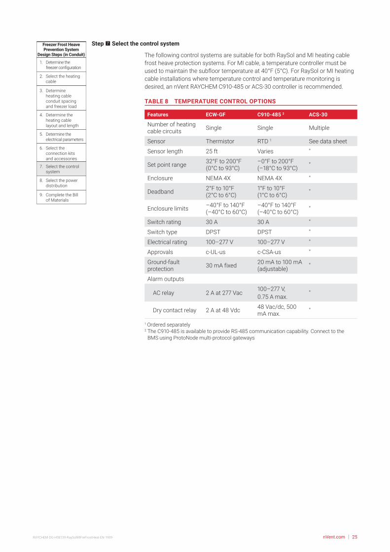
Step 7 Select the control system
The following control systems are suitable for both RaySol and MI heating cable frost heave protection systems. For MI cable, a temperature controller must be used to maintain the subfloor temperature at 40°F (5°C). For RaySol or MI heating cable installations where temperature control and temperature monitoring is desired, an nVent RAYCHEM C910-485 or ACS-30 controller is recommended.
TABLE 8 TEMPERATURE CONTROL OPTIONS
Features ECW-GF C910-485 2 ACS-30
Number of heating cable circuits Single Single Multiple
Sensor Thermistor RTD 1 See data sheet
Sensor length 25 ft Varies "
Set point range 32°F to 200°F (0°C to 93°C)
–0°F to 200°F (–18°C to 93°C) "
Enclosure NEMA 4X NEMA 4X "
Deadband 2°F to 10°F (2°C to 6°C)
1°F to 10°F (1°C to 6°C) "
Enclosure limits –40°F to 140°F (–40°C to 60°C)
–40°F to 140°F (–40°C to 60°C) "
Switch rating 30 A 30 A "
Switch type DPST DPST "
Electrical rating 100–277 V 100–277 V "
Approvals c-UL-us c-CSA-us "
Ground-fault protection 30 mA fixed 20 mA to 100 mA
(adjustable) "
Alarm outputs
AC relay 2 A at 277 Vac100–277 V, 0.75 A max.
"
Dry contact relay 2 A at 48 Vdc 48 Vac/dc, 500 mA max. "
1 Ordered separately2 The C910-485 is available to provide RS-485 communication capability. Connect to the
BMS using ProtoNode multi-protocol gateways

nVent.com | 26RAYCHEM-DG-H58139-RaySolMIFreFrostHeat-EN-1909
TABLE 9 CONTROL SYSTEMS
Catalog number Description
Electronic thermostats and accessories
ECW-GF Electronic ambient sensing controller with 30-mA ground-fault protection. The controller can be programmed to maintain temperatures up to 200°F (93°C) at voltages from 100 to 277 V and can switch current up to 30 Amperes. The ECW-GF is complete with a 25-ft (7.6-m) temperature sensor and is housed in a Type 4X rated enclosure. The controller features an AC/DC dry alarm contact relay.
An optional ground-fault display panel (ECW-GF-DP) can be added to provide ground-fault or alarm indication in applications where the controller is mounted in inaccessible locations.
ECW-GF-DP An optional remote display panel (ECW-GF-DP) can be added to provide ground-fault or alarm indication in applications where the controller is mounted in inaccessible locations.
MI-GROUND-KIT Grounding kit for nonmetallic enclosures (for MI only)
Electronic controllers and sensors
C910-485 The C910-485 is a compact, full featured, microprocessor-based, single-point commercial heating cable controller. The C910-485 provides control and monitoring of electrical heating cable circuits for commercial heating applications, with built-in ground-fault protection. The C910-485 can be set to monitor and alarm for high and low temperature, high and low current, ground-fault level, and voltage. Communications modules are available for remote control and configuration.
ACS-UIT2ACS-PCM2-5
The ACS-30 Advanced Commercial Control System is a multipoint electronic control and monitoring system for heat-tracing used in various commercial applications such as pipe freeze protection, roof and gutter de-icing, surface snow melting, hot water temperature maintenance and floor heating. The ACS-30 system can control up to 260 circuits with multiple networked ACS-PCM2-5 panels, with a single ACS-UIT2 user interface terminal. The ACS-PCM2-5 panel can directly control up to 5 individual heat-tracing circuits using electro-mechanical relays rated at 30 A up to 277 V.
By FieldServer Technologieswww.ProtoCessor.com
PROTOCESSORSERIAL ETHERNET
PROTONODE
FRAME GND- PWR+PWR
RS 485+RS 485 -RS 485 GND
S3S2S1S0B3B2B1B0
A7A6A5A4A3A2A1A0
ProtoNode-RER The ProtoNode is an external, high performance multi-protocol gateway for customers needing protocol translation between Building Management Systems (BMS) and the ACS-30 or C910-485 controllers.
The ProtoNode-RER is for BACnet ® or Metasys ® N2 systems.
RTD-200 RTD10CSRTD50CS
Stainless steel jacketed three-wire RTD (Resistance Temperature Detector) used with C910-485 and ACS-30 controllers.
RTD-200: 3-in (76 mm) temperature sensor with a 6-ft (1.8 m) lead wire and 1/2-in NPT bushing
RTD10CS: temperature sensor with a 10-ft (3 m) flexible armor, 18-in (457 mm) lead wire and 1/2-inch NPT bushing
RTD50CS: temperature sensor with a 50-ft (15.2 m) flexible armor, 18-in (457 mm) lead wire and 1/2-in NPT bushing
Example: RaySol and MI heating cables in conduitElectronic thermostat C910-485Quantity 1

nVent.com | 27RAYCHEM-DG-H58139-RaySolMIFreFrostHeat-EN-1909
Freezer Frost HeavePrevention System
Design Steps (in Conduit)
1. Determine the freezer configuration
2. Select the heating cable
4. Determine the heating cable layout and length
5. Determine the electrical parameters
6. Select the connection kits and accessories
7. Select the control system
8. Select the power distribution
9. Complete the Bill of Materials
3. Determine heating cable conduit spacing and freezer load
Step 8 Select the power distribution
FOR RAYSOL AND MI HEATING CABLE IN CONDUITPower to the heating cables can be provided in several ways:
• Directly to the power connection kits (RaySol only)
• Directly through the temperature controller
• Through external contactors or through HTPG power distribution panels
Single circuit controlHeating cable circuits that do not exceed the current rating of the selected controller can be switched directly (Fig. 14). When the total electrical load exceeds the rating of the controller, an external contactor is required.
RaySol systems without temperature control can be connected directly to the power connection kits from the ground-fault circuit breakers in subpanels.
Group controlIf the controller will activate multiple circuits (group control) then an external contactor must be used (Fig. 14).
Fig. 14 Single circuit and group control
Single circuit control Group control
Temperaturecontroller
1-poleGFEP breaker
1N
G
Heatingcable
øø supply
C
Temperaturecontroller
Contactor
1-poleGFEP breaker
N
G
ø2
ø1
ø3
3-phase 4-wiresupply (WYE)
3-pole mainbreaker
ø
ø 1 supply
N
Heating cable sheath, braid or ground
Heating cable sheath, braid or ground

nVent.com | 28RAYCHEM-DG-H58139-RaySolMIFreFrostHeat-EN-1909
Large systems with many circuits should use an HTPG power distribution panel. The HTPG is a dedicated power-distribution, control, ground-fault protection, monitoring, and alarm panel for freeze protection and broad temperature-maintenance heat-tracing applications. This enclosure contains an assembled circuit-breaker panelboard. Panels are equipped with ground-fault circuit breakers with or without alarm contacts. The group control package allows the system to operate automatically in conjunction with a temperature control system.
A
COMMON ALARMPUSH TO ACKNOWLEDGE
HAND/OFF/AUTO
123456
789
101112
Main circuitbreaker
Maincontactor
Distributionpanelboard
Fuse holder
C
POWER ON
TB 1
TB 2
ARR
Groundbus bar
Selector switch
Alarm relay(optional)
Terminals(optional)
Push button for light testing
Alarm horn (optional)
Alarm option shown above
Doordisconnect(optional)
Fig. 15 HTPG power distribution panel
NØ1Three-pole main
circuit breaker
Panelenergized
Contactorcoil
C NC
External controller/thermostat*
Hand AutoOff
Three-pole maincontactor
Ø3Ø2
Power connection
Heating cable
One-pole with 30-mAground-fault trip
(120/277 Vac)
Two-pole with 30-mAground-fault trip
(208/240 Vac)
Alarmremoteannunciation(with alarm option)
Heating cablecircuit
Heating cablecircuit
G
End seal
Heating cable shealth, braid or ground
Three-phase, 4 wire supply (Wye)
Fig. 16 HTPG power schematic

nVent.com | 29RAYCHEM-DG-H58139-RaySolMIFreFrostHeat-EN-1909
TABLE 10 POWER DISTRIBUTION
Catalog number Description
Power Distribution and Control Panels
A
COMMON ALARMPUSH TO ACKNOWLEDGE
HAND/OFF/AUTO
C
POWER ON
HTPG Heat-tracing power distribution panel with ground-fault and monitoring for group control.
Freezer Frost HeavePrevention System
Design Steps (in Conduit)
1. Determine the freezer configuration
2. Select the heating cable
4. Determine the heating cable layout and length
5. Determine the electrical parameters
6. Select the connection kits and accessories
7. Select the control system
8. Select the power distribution
9. Complete the Bill of Materials
3. Determine heating cable conduit spacing and freezer load
Step 9 Complete the Bill of Materials
If you used the Design Worksheet to document all your design parameters, you should have all the details necessary complete your Bill of Materials.

nVent.com | 30RAYCHEM-DG-H58139-RaySolMIFreFrostHeat-EN-1909
Design Step by Step MI Heating Cables Directly Embedded
Embedding cables directly in sand (recommended), concrete, or compacted fill subfloors has the advantage of simpler installation and reduced costs. The number of electrical circuits can be minimized considerably compared to a similar installation using conduit. If embedded in a concrete subfloor below the insulation, the cable must not cross any joints in the subfloor.
Follow these steps to design your system:
1 Determine the freezer configuration
2 Determine heat loss and freezer load
3 Select the heating cable, layout and length
4 Determine the heating cable spacing
5 Determine the electrical parameters
6 Select the accessories
7 Select the control system
8 Select the power distribution
9 Complete the Bill of Materials
The “MI Cables Directly Embedded Freezer Frost Heave Prevention Design Worksheet” on page 54 is included to help you document the project parameters that you will need for your project’s Bill of Materials.

nVent.com | 31RAYCHEM-DG-H58139-RaySolMIFreFrostHeat-EN-1909
Freezer Frost HeavePrevention System
Design Steps (Embedded)
1. Determine the freezer configuration
2. Determine heat loss and freezer load
4. Determine the heating cable spacing
5. Determine the electrical parameters
6. Select the accessories
7. Select the control system
8. Select the power distribution
9. Complete the Bill of Materials
3. Select the heating cable, layout and length
Step 1 Determine the freezer configuration
GATHERING INFORMATIONThe following information is required to complete the freezer frost heave prevention system design.
• Size and layout of freezer or ice arena
• Freezer operating temperature
• Insulation R-value
• Supply voltage and phase
• Control requirements
PREPARE SCALE DRAWINGDraw to scale the floor area to be heated. Carefully note the limits of the area to be heated. Show all concrete joints on the drawing and note the location and size of obstacles, such as floor drains, pipe penetrations, columns, fixtures, and voltage supply location.
Side A20'
(6.1 m)
Side B40'
(12.2 m)
Fig. 17 Typical freezer example – single-phase
DETERMINE FREEZER OPERATING TEMPERATUREDetermine the temperature at which your freezer operates. If it operates at more than one temperature, or if the operating temperature may be changed in the future, base the design on the lowest anticipated operating temperature.
RECORD INSULATION R-VALUEThe insulation R-value is the thermal resistance of the floor’s insulation. Normally the R-value will be printed on the insulation material. If that is not the case, you can calculate it by dividing the insulation thickness in inches by the insulation thermal conductivity.

nVent.com | 32RAYCHEM-DG-H58139-RaySolMIFreFrostHeat-EN-1909
Example: MI heating cables directly embedded – Single-phaseArea 40 ft x 20 ft = 800 ft2 (12.2 m x 6.1 m = 74 m2)Freezer operating temperature –30°F (–34°C)Insulation R-value R-20 (20 ft2·°F·hr/Btu)Supply voltage 208 V, single-phase
Example: MI heating cables directly embedded – Three-phaseArea 80 ft x 80 ft = 6400 ft2 (24.4 m x 24.4 m = 595 m2)Freezer operating temperature –20°F (–29°C)Insulation R-value R-20 (20 ft2·°F·hr/Btu)Supply voltage 208 V, three-phase
Freezer Frost HeavePrevention System
Design Steps (Embedded)
1. Determine the freezer configuration
2. Determine heat loss and freezer load
4. Determine the heating cable spacing
5. Determine the electrical parameters
6. Select the accessories
7. Select the control system
8. Select the power distribution
9. Complete the Bill of Materials
3. Select the heating cable, layout and length
Step 2 Determine heat loss and freezer load
In Table 11, we have calculated the heat loss for directly embedded MI heating cable systems based on the freezer temperatures and the floor insulation R-values; from this table, you will select your design power and freezer load. If your calculated R-value or freezer operating temperature does not match the values in the table, use the values that give the higher design power.
Within each cell, there are two numbers; design power and freezer load. Freezer load is the additional cooling load imposed on the cooling system by the freezer frost heave prevention heating cable. It is the heat transferred through the insulation into the freezer, expressed in W/ft2 (W/m2) of floor area.

nVent.com | 33RAYCHEM-DG-H58139-RaySolMIFreFrostHeat-EN-1909
TABLE 11 MI HEATING CABLE: DESIGN POWER REQUIREMENT AND FREEZER LOAD BASED ON 40°F (5°C) CONTROL
Freezer operating temperature
Floor insulation R-value (ft2·°F·hr/Btu)
R-10 R-20 R-30 R-40
30°F (–1°C)Design power W/ft2 (W/m2) 0.5 (5.4) 0.2 (2.2) 0.1 (1.1) 0.1 (1.1)
Freezer load W/ft2 (W/m2) 0.7 (7.5) 0.4 (4.3) 0.3 (3.2) 0.3 (3.2)
20°F (–7°C)Design power W/ft2 (W/m2) 0.6 (6.5) 0.4 (4.3) 0.2 (2.2) 0.1 (1.1)
Freezer load W/ft2 (W/m2) 0.8 (8.6) 0.5 (5.4) 0.4 (4.3) 0.3 (3.2)
10°F (–12°C)Design power W/ft2 (W/m2) 0.9 (9.7) 0.6 (6.5) 0.3 (3.2) 0.2 (2.2)
Freezer load W/ft2 (W/m2) 1.0 (10.8) 0.6 (6.5) 0.4 (4.3) 0.3 (3.2)
0°F (–18°C)Design power W/ft2 (W/m2) 1.1 (11.8) 0.7 (7.5) 0.5 (5.4) 0.3 (3.2)
Freezer load W/ft2 (W/m2) 1.3 (14.0) 0.8 (8.6) 0.5 (5.4) 0.4 (4.3)
–10°F (–23°C)Design power W/ft2 (W/m2) 1.4 (15.1) 0.8 (8.6) 0.6 (6.5) 0.4 (4.3)
Freezer load W/ft2 (W/m2) 1.5 (16.1) 0.8 (8.6) 0.6 (6.5) 0.5 (5.4)
–20°F (–29°C)Design power W/ft2 (W/m2) 1.6 (17.2) 0.9 (9.7) 0.7 (7.5) 0.5 (5.4)
Freezer load W/ft2 (W/m2) 1.8 (19.4) 1.0 (10.8) 0.7 (7.5) 0.6 (6.5)
–30°F (–34°C)Design power W/ft2 (W/m2) 1.7 (18.3) 1.1 (11.8) 0.8 (8.6) 0.6 (6.5)
Freezer load W/ft2 (W/m2) 2.0 (21.5) 1.1 (11.8) 0.8 (8.6) 0.6 (6.5)
–40°F (–40°C) Design power W/ft2 (W/m2) 2.0 (21.5) 1.2 (12.9) 0.8 (8.6) 0.7 (7.5)
Freezer load W/ft2 (W/m2) 2.3 (24.7) 1.2 (12.9) 0.8 (8.6) 0.7 (7.5)
Example: MI heating cables directly embedded – Single-phaseFreezer operating temperature –30°F (–34°C) (from Step 1)Insulation R-value R-20 (20 ft2·°F·hr/Btu) (from Step 1)Design power 1.1 W/ft2 (11.8 W/m2)Freezer load 1.1 W/ft2 (11.8 W/m2)
Example: MI heating cables directly embedded – Three-phaseFreezer operating temperature –20°F (–29°C) (from Step 1)Insulation R-value R-20 (20 ft2·°F·hr/Btu) (from Step 1)Design power 0.9 W/ft2 (9.7 W/m2)Freezer load 1.0 W/ft2 (10.8 W/m2)

nVent.com | 34RAYCHEM-DG-H58139-RaySolMIFreFrostHeat-EN-1909
Freezer Frost HeavePrevention System
Design Steps (Embedded)
1. Determine the freezer configuration
2. Determine heat loss and freezer load
4. Determine the heating cable spacing
5. Determine the electrical parameters
6. Select the accessories
7. Select the control system
8. Select the power distribution
9. Complete the Bill of Materials
3. Select the heating cable, layout and length
Step 3 Select the heating cable, layout and length
To select the correct MI heating cable for the heated area, you must determine the wattage required for the area or subsection area.
For small freezers, one heating cable may be sufficient. For large freezers, it may be necessary to divide the freezer into two or more equal subsection areas. To balance the load in a three-phase circuit, three cables will be required, or a multiple of three cables when more than one three-phase circuit is required. If the heating cables are to be embedded in a concrete subfloor, divide the area so that the heating cables will not cross any joints in the subfloor.
The heating cables shown in Table 12 are general purpose cables and may be used for a variety of applications depending on the supply voltage; the heating cables in Table 13 have been optimized for frost heave prevention applications. If assistance is required to select heating cables for irregular shaped areas or applications outside the scope of this design guide, contact your nVent representative for assistance in designing a custom heating cable.
SINGLE-PHASE SUPPLYSmall freezer areas require only one heating cable. Large freezer areas may require two or more heating cables.
• Divide large freezer areas into equal subsection areas, if possible.
• Calculate the power required for the total area (small freezers) or for each subsection area (large freezers) by multiplying the design power (from Table 11) by the total area or subsection area.
Power required = Design power x Total area (or Subsection area)
Simply select the heating cable from Table 12 or Table 13 based on the total area or subsection area. Under the appropriate voltage, make sure that the total area or subsection area falls within the minimum and maximum range of the “Area coverage” columns and verify that the “Cable wattage” shown directly across from the “Area coverage” is equal to or higher than the calculated “Power required” for the total area or subsection area (see example following).
Note: If two or more cables in the Tables meet the requirements, use the cable with the lower wattage.

nVent.com | 35RAYCHEM-DG-H58139-RaySolMIFreFrostHeat-EN-1909
In cases where the freezer area has been divided into equal subsections, select the appropriate number of heating cables. Where heating cables are directly embedded in concrete subfloors, calculate the wattage required for each area bounded by joints in the subfloor and select an appropriate cable for each area.
20'(6.1 m)
40'(12.2 m)
1Ø Supply Junction box
Fig. 18 Single-phase layout
Example: MI heating cables directly embedded – Single-phaseArea 800 ft2 (74 m2) (See Fig. 18)Design power 1.1 W/ft2 (11.8 W/m2) (from Step 2)Power required Design power x Area = 1.1 W/ft2 x 800 ft2 = 880 W (11.8 W/m2 x 74 m2 = 880 W)Supply voltage 208 V, single-phase (from Step 1)Catalog number SUB19Cable wattage 885 WHeated length 245 ft (74.7 m)Quantity 1

nVent.com | 36RAYCHEM-DG-H58139-RaySolMIFreFrostHeat-EN-1909
THREE-PHASE SUPPLYDesigning the frost heave prevention system using a three-phase voltage supply has the added advantages of fewer circuits, reduced distribution costs, and a balanced heating system load and is recommended for large freezers.
Three-phase voltages include 208/120 V, 480/277 V, and 600/347 V. When selecting heating cables for three-phase voltages, cable layout will be easier if the heating cables are wye connected (Fig. 19); therefore select the cables based on the phase-to-neutral voltage (e.g., select 277 V cables for a 480 V supply).
80'(24.4 m)
80'(24.4 m)
Junctionbox
Junctionbox
To temperature controller
3øsupply
Fig. 19 Three-phase wye connected heating cable layout
Since a balanced three-phase system requires three cables, each cable will occupy 1/3 of the freezer area when installed.
• Calculate the “Power required” by multiplying the design power from Table 11 by the total freezer area.
• Divide the total freezer area by three to determine the “Area coverage for each cable.”
• Calculate the "Wattage for each cable" by dividing the “Power required” by three.
Wattage for each cable = (Design power x Total freezer area) / 3
Simply select the heating cable from Table 12 on page 38 or Table 13 on page 39 based on the area coverage for each cable. Under the appropriate voltage, make sure that the area coverage for each cable falls within the minimum and maximum range of the “Area coverage” columns and verify that the “Cable wattage” shown directly across from the “Area coverage” is equal to or higher than the calculated “Wattage for each cable” (see example following). Three of the same cables are required for balanced three-phase systems.
Note: If two or more cables in the Tables meet the requirements, use the cable with the lower wattage.
Note: For very large freezers, it may be necessary to divide the freezer into subsections and use two or more three-phase circuits.

nVent.com | 37RAYCHEM-DG-H58139-RaySolMIFreFrostHeat-EN-1909
Example: MI heating cables directly embedded – Three-phaseArea 6400 ft2 (595 m2) (see Fig. 19)Design power 0.9 W/ft2 (9.7 W/m2) (from Step 2)Power required (Design Power x Area) = (0.9 W/ft2 x 6400 ft2) = 5760 W (9.7 W/m2 x 595 m2) = 5760 WArea coverage for each cable Area/3 = 6400 ft2/3 = 2133 ft2 (595 m2/3 = 198.3 m2)Wattage for each cable Power required/3 = 5760/3 = 1920 WSupply voltage 208 V, three-phase (from Step 1) (select 120 volt cable for wye connection)Catalog number SUB8Cable wattage 2300 W Cable voltage 120 VHeated length 550 ft (167.6 m)Quantity 3

nVent.com | 38RAYCHEM-DG-H58139-RaySolMIFreFrostHeat-EN-1909
TABLE 12 SELECTION TABLE FOR MI HEATING CABLES FOR DIRECTLY EMBEDDED CABLES
Catalog number
Area coverage Cable wattage
(W)
Heated length1
Heating cable current (A)2
Min (ft2)
Max (ft2)
Min (m2)
Max (m2) (ft) (m)
120 V and 208 V, three-phase wye
SUA3 205 700 19.1 65.1 500 140 42.7 4.2
SUA4 220 340 20.4 31.6 550 68 20.7 4.6
SUA7 300 480 27.9 44.6 750 95 29.0 6.3
SUA8 310 885 28.8 82.2 800 177 53.9 6.7
SUB1 420 660 39.0 61.3 1000 132 40.2 8.3
SUB2 400 1200 37.2 111.5 1000 240 73.1 8.3
SUB3 520 1400 48.3 130.1 1300 280 85.3 10.8
SUB4 600 1600 55.8 148.7 1500 320 97.5 12.5
SUB5 750 1300 69.7 120.8 1800 260 79.2 15.0
SUB6 780 1875 72.5 174.3 1900 375 114.3 15.8
SUB7 940 1550 87.4 144.1 2300 310 94.5 19.2
SUB8 930 2750 86.4 255.6 2300 550 167.6 19.2
SUB9 1250 3150 116.2 292.8 3000 630 192.0 25.0
SUB10 1700 3585 158.0 333.2 4300 717 218.5 35.8
208 V
SUA1 260 540 24.2 50.2 650 108 32.9 3.1
SUA6 650 1320 60.4 122.7 1560 264 80.5 7.5
SUB19 350 1225 32.5 113.8 885 245 74.7 4.3
SUB20 480 1700 44.6 158.0 1210 340 103.6 5.8
SUB21 650 2200 60.4 204.5 1640 440 134.1 7.9
SUB22 820 2625 76.2 244.0 2060 525 160.0 9.9
240 V
SUB19 350 1225 32.5 113.8 1175 245 74.7 4.9
SUB20 480 1700 44.6 158.0 1615 340 103.6 6.7
SUB21 650 2200 60.4 204.5 2180 440 134.1 9.1
SUB22 820 2625 76.2 244.0 2745 525 160.0 11.4
277 V and 480 V, three-phase wye
SUB19 400 1225 37.2 113.8 1565 245 74.7 5.6
SUB20 550 1700 51.1 158.0 2150 340 103.6 7.8
SUB21 720 2200 66.9 204.5 2900 440 134.1 10.5
SUB22 940 2625 87.4 244.0 3650 525 160.0 13.2
347 V and 600 V, three-phase wye
SUB11 540 1125 50.2 104.6 1400 225 68.6 4.0
SUB12 770 1550 71.6 144.1 1950 310 94.5 5.6
SUB13 1060 2140 98.5 198.9 2700 428 130.5 7.8
SUB14 1440 2740 133.8 254.6 3700 548 167.0 10.71 Tolerance on heating cable length is –0% to +3%2 Single-phase current shown
Note: Type SUA cables supplied with 7 ft (2.1 m) long cold lead; type SUB cables supplied with 15 ft (4.6 m) long cold leads.

nVent.com | 39RAYCHEM-DG-H58139-RaySolMIFreFrostHeat-EN-1909
TABLE 13 SELECTION TABLE FOR MI HEATING CABLES FOR DIRECTLY EMBEDDED CABLES
Catalog number
Area coverage Cable wattage
(W)
Heated length 1
Heating cable current (A)2
Min (ft2)
Max (ft2)
Min (m2)
Max (m2) (ft) (m)
120 V and 208 V, three-phase Wye
FFHP1 163 290 15.1 27.0 405 58 17.7 3.4
FFHP2 205 360 19.1 33.5 510 72 22.0 4.3
FFHP3 231 415 21.5 38.6 580 83 25.3 4.8
FFHP4 282 510 26.2 47.4 705 102 31.1 5.9
FFHP5 328 585 30.5 54.4 820 117 35.7 6.8
FFHP6 392 700 36.4 65.1 980 140 42.7 8.2
FFHP7 450 800 41.8 74.3 1125 160 48.8 9.4
FFHP8 519 925 48.2 86.0 1300 185 56.4 10.8
FFHP9 637 1130 59.2 105.0 1590 226 68.9 13.3
FFHP10 733 1310 68.1 121.7 1830 262 79.9 15.3
FFHP11 900 1600 83.6 148.7 2250 320 97.6 18.8
FFHP12 1186 2130 110.2 198.0 2965 426 129.9 24.7
FFHP13 1470 2640 136.6 245.4 3675 528 161.0 30.6
FFHP14 1862 3320 173.0 308.6 4650 664 202.4 38.8
208 V
FFHP15 281 505 26.1 46.9 700 101 30.8 3.4
FFHP16 352 630 32.7 58.6 880 126 38.4 4.2
FFHP17 401 720 37.2 66.9 1000 144 43.9 4.8
FFHP18 492 880 45.7 81.8 1230 176 53.7 5.9
FFHP19 568 1015 52.8 94.3 1420 203 61.9 6.8
FFHP20 678 1215 63.0 112.9 1700 243 74.1 8.2
FFHP21 778 1390 72.3 129.2 1945 278 84.8 9.4
FFHP22 901 1600 83.8 148.7 2250 320 97.6 10.8
FFHP23 1098 1970 102.1 183.1 2745 394 120.1 13.2
FFHP24 1268 2275 117.8 211.4 3170 455 138.7 15.2
FFHP25 1553 2785 144.4 258.8 3885 557 169.8 18.7
240 V
FFHP26 326 580 30.3 53.9 815 116 35.4 3.4
FFHP27 407 725 37.9 67.4 1020 145 44.2 4.3
FFHP28 463 830 43.0 77.1 1160 166 50.6 4.8
FFHP29 567 1015 52.7 94.3 1420 203 61.9 5.9
FFHP30 656 1170 61.0 108.7 1640 234 71.3 6.8
FFHP31 786 1395 73.1 129.6 1965 279 85.1 8.2
FFHP32 900 1600 83.6 148.7 2250 320 97.6 9.4
FFHP33 1038 1850 96.5 171.9 2600 370 112.8 10.8
FFHP34 1274 2260 118.4 210.0 3185 452 137.8 13.3
FFHP35 1471 2610 136.7 242.6 3680 522 159.1 15.3
FFHP36 1800 3200 167.3 297.4 4500 640 195.1 18.81 Tolerance on heating cable length is –0% to +3%.2 Single-phase current shown
Note: Type FFHP cables supplied with 15 ft (4.6 m) long cold leads.

nVent.com | 40RAYCHEM-DG-H58139-RaySolMIFreFrostHeat-EN-1909
TABLE 13 SELECTION TABLE FOR MI HEATING CABLES FOR DIRECTLY EMBEDDED CABLES
Catalog number
Area coverage Cable wattage
(W)
Heated length 1
Heating cable current (A)2
Min (ft2)
Max (ft2)
Min (m2)
Max (m2) (ft) (m)
277 V and 480 V, three-phase wye
FFHP37 375 670 34.9 62.3 940 134 40.9 3.4
FFHP38 468 840 43.5 78.1 1170 168 51.2 4.2
FFHP39 536 955 49.8 88.8 1340 191 58.2 4.8
FFHP40 656 1170 60.9 108.7 1640 234 71.3 5.9
FFHP41 758 1350 70.4 125.5 1895 270 82.3 6.8
FFHP42 908 1610 84.4 149.6 2270 322 98.2 8.2
FFHP43 1037 1850 96.4 171.9 2590 370 112.8 9.4
FFHP44 1201 2130 111.6 198.0 3000 426 129.9 10.8
FFHP45 1462 2625 135.8 244.0 3655 525 160.1 13.2
FFHP46 1697 3015 157.7 280.2 4240 603 183.8 15.3
FFHP47 2074 3700 192.7 343.9 5185 740 225.6 18.7
347 V and 600 V, three-phase wye
FFHP48 470 840 43.7 78.1 1175 168 51.2 3.4
FFHP49 588 1050 54.7 97.6 1470 210 64.0 4.2
FFHP50 672 1195 62.4 111.1 1680 239 72.9 4.8
FFHP51 819 1470 76.1 136.6 2050 294 89.6 5.9
FFHP52 950 1690 88.3 157.1 2375 338 103.0 6.8
FFHP53 1133 2025 105.3 188.2 2830 405 123.5 8.2
FFHP54 1295 2325 120.3 216.1 3240 465 141.8 9.3
FFHP55 1500 2675 139.4 248.6 3750 535 163.1 10.8
FFHP56 1838 3275 170.8 304.4 4600 655 199.7 13.3
FFHP57 2126 3775 197.6 350.8 5315 755 230.2 15.31 Tolerance on heating cable length is –0% to +3%.2 Single-phase current shown
Note: Type FFHP cables supplied with 15 ft (4.6 m) long cold leads.

nVent.com | 41RAYCHEM-DG-H58139-RaySolMIFreFrostHeat-EN-1909
Freezer Frost HeavePrevention System
Design Steps (Embedded)
1. Determine the freezer configuration
2. Determine heat loss and freezer load
4. Determine the heating cable spacing
5. Determine the electrical parameters
6. Select the accessories
7. Select the control system
8. Select the power distribution
9. Complete the Bill of Materials
3. Select the heating cable, layout and length
Step 4 Determine the heating cable spacing
To determine the spacing between runs of heating cables, use the formula below:
Cable spacing (in) = Area (ft2) x 12 in
Heated length (ft)
Cable spacing (cm) = Area (m2) x 100 cm
Heated length (m)
Note: If a large area has been divided into subsections or if a three-phase voltage supply is used, the “Area” in the above equations will be the subsection area or area coverage for each cable and the “Heated length” will be the length of the selected cable.
Example: MI heating cables directly embedded – Single-phaseArea 800 ft2 (74 m2) (from Step 3)Catalog number SUB19 (from Step 3)Heated length 245 ft (74.7 m) (from Step 3)Cable spacing 800 ft2 x 12 / 245 ft = 39.2 in rounded to 39 in 74 m2 x 100 / 74.7 m = 99.1 cm rounded to 99 cm
Example: MI heating cables directly embedded – Three-phaseArea coverage for each cable 2133 ft2 (198.3 m2) (from Step 3)Catalog number SUB8 (from Step 3)Heated length 550 ft (167.6 m) (from Step 3)Cable spacing 2133 ft2 x 12 / 550 ft = 46.5 in rounded to 47 in 198.3 m2 x 100 / 167.6 m = 118.3 cm rounded to 118 cm
Freezer Frost HeavePrevention System
Design Steps (Embedded)
1. Determine the freezer configuration
2. Determine heat loss and freezer load
4. Determine the heating cable spacing
5. Determine the electrical parameters
6. Select the accessories
7. Select the control system
8. Select the power distribution
9. Complete the Bill of Materials
3. Select the heating cable, layout and length
Step 5 Determine the electrical parameters
DETERMINE NUMBER OF CIRCUITSFor single-phase circuits, when connecting individual heating cables to circuit breakers, the cable current draw must not exceed 80% of the circuit breaker rating. To reduce the number of circuits, multiple heating cables may be connected in parallel. When multiple cables are connected in parallel, the total of the individual heating cable currents must not exceed 80% of the circuit breaker rating. The single-phase heating cable current is shown in Table 12 and Table 13.
For three-phase circuits used in frost heave protection systems, the three heating cables are generally connected in the wye configuration shown in Fig. 21 on page 46. For a wye connected three-phase circuit, the current draw is the same as the single-phase heating cable current and must not exceed 80% of the 3-pole circuit breaker rating.
A 30-mA ground-fault protection device (GFPD) must be used to provide protection from arcing or fire, and to comply with warranty requirements, agency certifications, and national electrical codes. If the heating cable is improperly installed, or physically damaged, sustained arcing or fire could result. If arcing does occur, the fault current may be too low to trip conventional circuit breakers.

nVent.com | 42RAYCHEM-DG-H58139-RaySolMIFreFrostHeat-EN-1909
WARNING: To minimize the danger of fire from sustained electrical arcing if the heating cable is damaged or improperly installed, and to comply with the requirements of nVent, agency certifications, and national electrical codes, ground-fault equipment protection must be used on each heating cable branch circuit. Arcing may not be stopped by conventional circuit protection.
SELECT BRANCH CIRCUIT BREAKER SIZERecord the number and ratings of the circuit breakers to be used. Use ground-fault protection devices (GFPDs) for all applications. For three-phase circuits, ground fault may be accomplished using a shunt trip 3-pole breaker and a ground fault sensor.
DETERMINE TRANSFORMER LOADThe total transformer load is the sum of the wattages of the selected heating cables. Calculate the Total Transformer Load as follows:
Transformer load (kW) = Cable1 (W) + Cable2 (W) + Cable3 (W)... + CableN (W)
1000
Example: MI heating cables directly embedded – Single-phaseAmps 4.3 A (from Table 12)Circuit breaker size 15 A breaker, 80% loading 12 ANumber of circuit breakers 1Cable power output 885 W (from Step 3)Number of cables 1 (from Step 3)Transformer load 885 W / 1000 = 0.9 kW
Example: MI heating cables directly embedded – Three-phaseAmps/cable 19.2 A (from Table 12)Circuit breaker size 25 A, 3-pole breaker, 80% loading 20 ANumber of circuit breakers 1 (3 cables wye connected – see Fig. 21)Cable power output 2300 W (from Step 3)Number of cables 3 (from Step 3)Total Transformer load (2300 W x 3) / 1000 = 6.9 kW
Record the number and ratings of the circuit breakers to be used and total transformer load on the worksheet.

nVent.com | 43RAYCHEM-DG-H58139-RaySolMIFreFrostHeat-EN-1909
Freezer Frost HeavePrevention System
Design Steps (Embedded)
1. Determine the freezer configuration
2. Determine heat loss and freezer load
4. Determine the heating cable spacing
5. Determine the electrical parameters
6. Select the accessories
7. Select the control system
8. Select the power distribution
9. Complete the Bill of Materials
3. Select the heating cable, layout and length
Step 6 Select the accessories
For your embedded system, determine the number of junction boxes required.
SELECT JUNCTION BOXSelect a UL Listed and/or CSA Certified junction box that is suitable for the location, such as the D1297TERM4. Use a box with minimum internal volume of 16 cubic inches if the box is metallic and 19 cubic inches if the box is not metallic. Metal junction boxes are recommended.
Note: The junction box must be accessible according to the national electrical codes.
After determining the number of heating cables required, the number of circuits, and the junction box locations, do a trial layout. In making the trial layout, follow these recommendations:
• Install the heating cables in a sand layer beneath the insulation.
• Maintain the design spacing within 4 in (10 cm).
• When directly embedded in the concrete floor, do not cross expansion joints in the floor.
• Do not route the cables closer than 4 in (10 cm) to the edge of the subfloor, drains, anchors, or other material.
TABLE 14 ACCESSORIES
Catalog number Description
Standard packaging Usage
D1297TERM4 A cast aluminum junction box (Type 3) for installation in nonhazardous and CID2 locations. Three 1/2-in NPT entries on bottom, provided with plugs. Includes 4-pole terminal block (CSA - 600 V, 65 A, 18 - 6 AWG; UL - 300 V, 65 A, 18 - 6 AWG). External mounting feet. CSA approved for Class I, Div. 2, Groups A, B, C, and D. (for MI only)Enclosure dimensions: 6 in x 6 in x 4 in (150 mm x 150 mm x 100 mm).
1 For MI cable only
Example: MI heating cables directly embedded – Single-phaseJunction box D1297TERM4Quantity required 1
Example: MI heating cables directly embedded – Three-phaseJunction box Contractor suppliedQuantity required 2

nVent.com | 44RAYCHEM-DG-H58139-RaySolMIFreFrostHeat-EN-1909
Freezer Frost HeavePrevention System
Design Steps (Embedded)
1. Determine the freezer configuration
2. Determine heat loss and freezer load
4. Determine the heating cable spacing
5. Determine the electrical parameters
6. Select the accessories
7. Select the control system
8. Select the power distribution
9. Complete the Bill of Materials
3. Select the heating cable, layout and length
Step 7 Select the control system
For MI cable, a temperature controller must be used to maintain the subfloor temperature at 40°F (4°C). For installations where temperature control and temperature monitoring is desired, a C910-485 or ACS-30 controller is recommended. For additional information on temperature controller options, refer to "Table 8" on page 25.
TABLE 15 CONTROL SYSTEMS
Catalog number Description
Electronic thermostats and accessories
ECW-GF Electronic ambient sensing controller with 30-mA ground-fault protection. The controller can be programmed to maintain temperatures up to 200°F (93°C) at voltages from 100 to 277 V and can switch current up to 30 Amperes. The ECW-GF is complete with a 25-ft (7.6-m) temperature sensor and is housed in a Type 4X rated enclosure. The controller features an AC/DC dry alarm contact relay.An optional ground-fault display panel (ECW-GF-DP) can be added to provide ground-fault or alarm indication in applications where the controller is mounted in inaccessible locations.
ECW-GF-DP An optional remote display panel (ECW-GF-DP) that can be added to provide ground-fault or alarm indication in applications where the controller is mounted in inaccessible locations.
MI-GROUND-KIT Grounding kit for nonmetallic enclosures (for MI only)
Electronic controllers and sensors
C910-485 The C910-485 is a compact, full featured, microprocessor-based, single-point commercial heating cable controller. The C910-485 provides control and monitoring of electrical heating cable circuits for commercial heating applications, with built-in ground-fault protection. The C910-485 can be set to monitor and alarm for high and low temperature, high and low current, ground-fault level, and voltage. Communications modules are available for remote control and configuration.

nVent.com | 45RAYCHEM-DG-H58139-RaySolMIFreFrostHeat-EN-1909
TABLE 15 CONTROL SYSTEMS
Catalog number Description
ACS-UIT2ACS-PCM2-5
The ACS-30 Advanced Commercial Control System is a multipoint electronic control and monitoring system for heat-tracing used in various commercial applications such as pipe freeze protection, roof and gutter de-icing, surface snow melting, hot water temperature maintenance and floor heating. The ACS-30 system can control up to 260 circuits with multiple networked ACS-PCM2-5 panels, with a single ACS-UIT2 user interface terminal. The ACS-PCM2-5 panel can directly control up to 5 individual heat-tracing circuits using electromechanical relays rated at 30 A up to 277 V.
By FieldServer Technologieswww.ProtoCessor.com
PROTOCESSORSERIAL ETHERNET
PROTONODE
FRAME GND- PWR+PWR
RS 485+RS 485 -RS 485 GND
S3S2S1S0B3B2B1B0
A7A6A5A4A3A2A1A0
ProtoNode-RER The ProtoNode is an external, high performance multi-protocol gateway for customers needing protocol translation between Building Management Systems (BMS) and the ACS-30 or C910-485 controllers.The ProtoNode-RER is for BACnet® or Metasys® N2 systems.
RTD-200 RTD10CSRTD50CS
Stainless steel jacketed three-wire RTD (Resistance Temperature Detector) used with C910-485 and ACS-30 controllers.RTD-200: 3-in (76 mm) temperature sensor with a 6-ft (1.8 m) lead wire and 1/2-in NPT bushingRTD10CS: temperature sensor with a 10-ft (3 m) flexible armor, 18-in (457 mm) lead wire and 1/2-inch NPT bushingRTD50CS: temperature sensor with a 50-ft (15.2 m) flexible armor, 18-in (457 mm) lead wire and 1/2-in NPT bushing
Example: MI heating cables directly embedded – Single-phaseSingle circuit, electronic controller C910-485Quantity 1
Example: MI heating cables directly embedded – Three-phaseSingle circuit, monitoring requested ACS-30*Quantity 1*Use ACS-30 General part number (P000001232) for custom three-phase panels. Please contact your nVent representative for a custom ACS-PCM2-5 panel quotation.
Freezer Frost HeavePrevention System
Design Steps (Embedded)
1. Determine the freezer configuration
2. Determine heat loss and freezer load
4. Determine the heating cable spacing
5. Determine the electrical parameters
6. Select the accessories
7. Select the control system
8. Select the power distribution
9. Complete the Bill of Materials
3. Select the heating cable, layout and length
Step 8 Select the power distribution
Power to the heating cables can be provided in three ways:
1. Directly through the temperature controller
2. Through external contactors activated by a temperature controller
3. Through an HTPG power distribution panel
SINGLE CIRCUIT CONTROLHeating cable circuits that do not exceed the current rating of the selected controller can be switched directly (Fig. 20). When the total electrical load exceeds the rating of the controller or if a single-pole temperature controller is used to control a three-phase circuit (Fig. 21), an external contactor is required.
GROUP CONTROLIf the temperature controller will activate multiple single-phase or three-phase circuits (group control), then an external contactor must be used. In Fig. 20, three single-phase circuits are activated by a temperature controller through an external contactor.

nVent.com | 46RAYCHEM-DG-H58139-RaySolMIFreFrostHeat-EN-1909
Single circuit control Group control
Temperaturecontroller
1-poleGFEP breaker
1N
G
Heatingcable
øø supply
C
Temperaturecontroller
Contactor
1-poleGFEP breaker
N
G
ø2
ø1
ø3
3-phase 4-wiresupply (WYE)
3-pole mainbreaker
ø
ø 1 supply
N
Heating cable sheath, braid or ground
Heating cable sheath, braid or ground
Fig. 20 Single circuit and group control
A B C
A
B
C
N
C
MCB
To groundfault module
3-pole contactor120 volt coil
3-pole circuitbreaker with shunt
trip/external ground-fault sensor
Ground faultsensor
Ground
Three-phase4-wire supply
Heating cablesheath, braid or ground
Temperaturecontroller
to120 V
Note: For Wye connected heating cables, the current in the supply feeder, contactor, and breakers is equal to the ‘Single Phase Heating Cable Current.’
Note: Heating cable voltage is the sameas the phase-to-neutral voltage (VØ-Ø / 3 )
Fig. 21 Typical three-phase wye connected cables with temperature controller and contactor

nVent.com | 47RAYCHEM-DG-H58139-RaySolMIFreFrostHeat-EN-1909
Large systems with many circuits should use an HTPG power distribution panel. The HTPG is a dedicated power-distribution, control, ground-fault protection, monitoring, and alarm panel for freeze protection and broad temperature-maintenance heat-tracing applications. This enclosure contains an assembled circuit-breaker panelboard. Panels are equipped with ground-fault circuit breakers with or without alarm contacts. The group control package allows the system to operate automatically in conjunction with a temperature control system.
A
COMMON ALARMPUSH TO ACKNOWLEDGE
HAND/OFF/AUTO
123456
789
101112
Main circuitbreaker
Maincontactor
Distributionpanelboard
Fuse holder
C
POWER ON
TB 1
TB 2
ARR
Groundbus bar
Selector switch
Alarm relay(optional)
Terminals(optional)
Push button for light testing
Alarm horn (optional)
Alarm option shown above
Doordisconnect(optional)
Fig. 22 HTPG power distribution panel
NØ1Three-pole main
circuit breaker
Panelenergized
Contactorcoil
C NC
External controller/thermostat*
Hand AutoOff
Three-pole maincontactor
Ø3Ø2
Power connection
Heating cable
One-pole with 30-mAground-fault trip
(120/277 Vac)
Two-pole with 30-mAground-fault trip
(208/240 Vac)
Alarmremoteannunciation(with alarm option)
Heating cablecircuit
Heating cablecircuit
G
End seal
Heating cable shealth, braid or ground
Three-phase, 4 wire supply (Wye)
Fig. 23 Typical HTPG power schematic

nVent.com | 48RAYCHEM-DG-H58139-RaySolMIFreFrostHeat-EN-1909
TABLE 16 POWER DISTRIBUTION
Catalog number Description
Power distribution and control panels
A
COMMON ALARMPUSH TO ACKNOWLEDGE
HAND/OFF/AUTO
C
POWER ON
HTPG Heat-tracing power distribution panel with ground-fault and monitoring for group control.
Freezer Frost HeavePrevention System
Design Steps (Embedded)
1. Determine the freezer configuration
2. Determine heat loss and freezer load
4. Determine the heating cable spacing
5. Determine the electrical parameters
6. Select the accessories
7. Select the control system
8. Select the power distribution system
9. Complete the Bill of Materials
3. Select the heating cable, layout and length
Step 9 Complete the Bill of Materials
If you used the Design Worksheet to document all your design parameters, you should have all the details necessary complete your Bill of Materials.

nVent.com | 49RAYCHEM-DG-H58139-RaySolMIFreFrostHeat-EN-1909
RAYSOL AND MI HEATING CABLE IN CONDUIT FREEZER FROST HEAVE PREVENTION DESIGN WORKSHEET
Step 1 Determine the freezer configuration (RaySol and MI heating cable systems)
Determine freezer area (from scale drawing) Determine freezer operating temperature
Record insulation R-value
Supply voltage
x =Side A (length)
(ft/m)Side B (width)
(ft/m)Freezer area
(ft2/m2)°F/°C ft2·°F·hr/Btu Volts
Example: RaySol and MI heating cables
80 ftx
40 ft=
3200 ft2 –20°F R-40 (40 ft2·°F·hr/Btu) 208 Volts
Side A (length) (ft)
Side B (width) (ft)
Freezer area (ft2)
Step 2 Select the heating cable
RaySol heating cable MI heating cable
Supply voltage 120 V 208 V 240 V 277 V
Catalog number: ____________________
Supply voltage 120 V 208 V 277 V
Freezer side A length (ft/m): ____________________Catalog number: ____________________Power output (W): ____________________
Example: RaySol heating cableSupply voltage 208 VCatalog number: RaySol-2
Supply voltage 208 VFreezer side A length: 80 ftCatalog number: FFHPC30Power output: 475 W
Step 3 Determine the heating cable conduit spacing and freezer load (RaySol and MI heating cable systems)
Based on the insulation R-value and freezer operating temperature you recorded in Step 1, use Table 4 to select the following:
Conduit spacing (in/cm) ___________________________ Freezer load (W/ft2) (W/m2) ___________________________
Example: For RaySol and MI heating cablesConduit spacing: 96 in Freezer load: 0.5 W/ft2

nVent.com | 50RAYCHEM-DG-H58139-RaySolMIFreFrostHeat-EN-1909
Step 4 Determine the heating cable layout and length
RaySol heating cable in conduit MI heating cable in conduit
1. Estimate the number of conduit runs Imperial
x 12( ) =/Estimated number
of conduit runsSide B (ft) Conduit spacing (in)
x 100( ) =/Estimated number
of conduit runsSide B (m) Conduit spacing (cm)
x 12( ) =/Estimated number
of conduit runs
40 ft 96 in 5
Side B (ft) Conduit spacing (in)
Metric
x 12( ) =/Estimated number
of conduit runsSide B (ft) Conduit spacing (in)
x 100( ) =/Estimated number
of conduit runsSide B (m) Conduit spacing (cm)
x 12( ) =/Estimated number
of conduit runs
40 ft 96 in 5
Side B (ft) Conduit spacing (in)
If necessary, round to the next whole number
Example: RaySol heating cable Example: MI heating cable
x 12( ) =/Estimated number
of conduit runsSide B (ft) Conduit spacing (in)
x 100( ) =/Estimated number
of conduit runsSide B (m) Conduit spacing (cm)
x 12( ) =/Estimated number
of conduit runs
40 ft 96 in 5
Side B (ft) Conduit spacing (in)
2. Estimate the heating cable length required for conduit runs 2. Determine the number of MI heating cables
5
x 12( ) =/Estimated number
of conduit runsSide B (ft) Conduit spacing (in)
=Number of conduit runs
5
Number of heating cables required
=Number of conduit runs Number of heating cables required
x 100( ) =/Estimated number
of conduit runsSide B (m) Conduit spacing (cm)
Example: RaySol heating cable Example: MI heating cable5
x 12( ) =/Estimated number
of conduit runsSide B (ft) Conduit spacing (in)
=Number of conduit runs
5
Number of heating cables required
=Number of conduit runs Number of heating cables required
x 100( ) =/Estimated number
of conduit runsSide B (m) Conduit spacing (cm)
3. Determine the maximum circuit length (see Table 5)
Is the heating cable length required > the maximum circuit length?
No – One circuit is sufficient Yes – Multiple circuits are required
Example: RaySol heating cable
Is the heating cable length required > the maximum circuit length? No – One circuit is sufficient
4. Determine layoutIs Side A x 2 ≤ to the maximum circuit length?
Yes – Conduit can be looped in hairpin configuration Odd number of conduit runs – One conduit run will be straight Even number of conduit runs – All conduit run are looped in hairpin configuration
No – Use a straight run layout
x 12( ) =/Estimated number
of conduit runsSide B (ft) Conduit spacing (in)
x 100( ) =/Estimated number
of conduit runsSide B (m) Conduit spacing (cm)
x 12( ) =/Estimated number
of conduit runs
40 ft 96 in 5
Side B (ft) Conduit spacing (in)
80 ft 5 400 ft
x =Heating cable
length required (ft/m)Side A (ft/m) Number of
conduit runs
x =Heating cable
length required (ft)Side A (ft) Number of
conduit runs
80 ft 5 400 ft
x =Heating cable
length required (ft/m)Side A (ft/m) Number of
conduit runs
x =Heating cable
length required (ft)Side A (ft) Number of
conduit runs
Maximum circuit length(ft/m)
Heating cablelength required
(ft/m)
Supply voltage(V)
Maximum circuit length(ft)
400 ft 208 V 410 ft
Heating cablelength required (ft)
Supply voltage(V)
Number of circuits Power supply
Number of circuits Power supply
1 One 20 A circuit breaker
Maximum circuit length(ft/m)
Heating cablelength required
(ft/m)
Supply voltage(V)
Maximum circuit length(ft)
400 ft 208 V 410 ft
Heating cablelength required (ft)
Supply voltage(V)
Number of circuits Power supply
Number of circuits Power supply
1 One 20 A circuit breaker

nVent.com | 51RAYCHEM-DG-H58139-RaySolMIFreFrostHeat-EN-1909
Example: RaySol heating cableIs Side A x 2 ≤ to the maximum circuit length? Yes – Conduit can be looped in hairpin configuration Odd number of conduit runs – One conduit run will be straightLayout: Run in two hairpin loops and one straight run
5. Determine end allowances and connection kit allowances (see Table 6) and total heating cable length required. Determine end allowances
Example: RaySol heating cable
Determine connection kit allowances
Example: RaySol heating cable
Determine total heating cable length required for conduit runs and allowances
Example: RaySol heating cable
Number of straight run conduits
Heating cable length for end allowances
x 8 ft =
Number ofhairpin conduits
x 8 ft =
Number of straight run conduits
Heating cable length for end allowances
x 8 ft =
Number ofhairpin conduits
x 8 ft =2 16 ft
1 8 ft
24 ft
Number of straight run conduits
Heating cable length for end allowances
x 8 ft =
Number ofhairpin conduits
x 8 ft =
Number of straight run conduits
Heating cable length for end allowances
x 8 ft =
Number ofhairpin conduits
x 8 ft =2 16 ft
1 8 ft
24 ft
Number of FTC-XCkits for straight run conduits
Heating cable length for connection kit allowances
x 4 ft =
Number of FTC-XCkits for hairpin conduits
x 4 ft =
1 4 ft
12 ft
2 8 ft
Number of FTC-XCkits for straight run conduits
Heating cable length for connection kit allowances
x 4 ft =
Number of FTC-XCkits for hairpin conduits
x 4 ft =
Number of FTC-XCkits for straight run conduits
Heating cable length for connection kit allowances
x 4 ft =
Number of FTC-XCkits for hairpin conduits
x 4 ft =
1 4 ft
12 ft
2 8 ft
Number of FTC-XCkits for straight run conduits
Heating cable length for connection kit allowances
x 4 ft =
Number of FTC-XCkits for hairpin conduits
x 4 ft =
=++Heating cable lengthfor conduit runs (ft/m)
Heating cable lengthfor end allowances (ft/m)
Heating cable lengthfor connection kitallowances (ft/m)
Total heating cable length required (ft/m)
=++Heating cable lengthfor conduit runs (ft)
Heating cable lengthfor end allowances (ft)
Heating cable lengthfor connection kitallowances (ft)
Total heating cable length required (ft)
400 ft 24 ft 12 ft 436 ft

nVent.com | 52RAYCHEM-DG-H58139-RaySolMIFreFrostHeat-EN-1909
Step 5 Determine the electrical parameters
RaySol heating cable in conduit MI heating cable in conduit
Determine number of circuitsCircuit breaker rating (A): ___________ (from Step 4, Table 5)Number of circuits: ____________ (from Step 4)
Determine circuit breaker rating and number of circuitsCircuit breaker rating (A): ______________Number of circuits: ______________
Calculate circuit breaker load Calculate circuit breaker rating and number of circuits
Example: RaySol heating cable Example: MI heating cable
Calculate total transformer load Calculate total transformer load
Total transformerload (kW)
Cable1 (W)+( )Cable2 (W)
+CableN (W)Cable3 (W)...
+ / 1000 =
Total transformerload
Cable1
+475 W
Cable2
+475 W
Cable3
+475 W
Cable4
+475 W
Cable5
475 W 2.4 kW)( / 1000 =
Example: RaySol heating cable Example: MI heating cable
Total transformerload (kW)
Cable1 (W)+( )Cable2 (W)
+CableN (W)Cable3 (W)...
+ / 1000 =
Total transformerload
Cable1
+475 W
Cable2
+475 W
Cable3
+475 W
Cable4
+475 W
Cable5
475 W 2.4 kW)( / 1000 =
Step 6 Select the connection kits and accessories
Connection kits and accessories Description Quantity
FTC-XC FTC-HST RayClic-E D1297TERM4
Power connection and end sealLow-profile splice/teeExtra end sealCast aluminum junction box (for MI cable only)
________________________________________________
Example: FTC-XC Power connection and end seal 3 (for RaySol)
D1297TERM4 Cast aluminum junction box (for MI cable only) 5 (for MI)
20 A 208 V 3.3 kW
Circuit breakerrating (A)
x( x0.8Circuit breaker loadSupply
voltage
) =/ 1000
Circuit breakerrating (A)
x( x0.8Circuit breaker load
(kW)Supplyvoltage
) =/ 1000Total current
(A)
*Use next largest available circuit breaker or break into smaller circuits
= =x 1.25( )Minimum circuit
breaker rating (A)*Circuit breaker
rating (A)
=Number of circuits
11.5 A 14.4 A 15 A
1
Total current (A)
*Use next largest available circuit breaker or break into smaller circuits
= =x 1.25( )Minimum circuit
breaker rating (A)*Circuit breaker
rating (A)
=Number of circuits
20 A 208 V 3.3 kW
Circuit breakerrating (A)
x( x0.8Circuit breaker loadSupply
voltage
) =/ 1000
Circuit breakerrating (A)
x( x0.8Circuit breaker load
(kW)Supplyvoltage
) =/ 1000
Total current (A)
*Use next largest available circuit breaker or break into smaller circuits
= =x 1.25( )Minimum circuit
breaker rating (A)*Circuit breaker
rating (A)
=Number of circuits
11.5 A 14.4 A 15 A
1
Total current (A)
*Use next largest available circuit breaker or break into smaller circuits
= =x 1.25( )Minimum circuit
breaker rating (A)*Circuit breaker
rating (A)
=Number of circuits
Total transformer load (kW)
CBL1
+CBL2
+CBLNCBL3 ...
+ =
Total transformer load (kW)
CBL1
=3.3 kW 3.3 kW
Total transformer load (kW)
CBL1
+CBL2
+CBLNCBL3 ...
+ =
Total transformer load (kW)
CBL1
=3.3 kW 3.3 kW
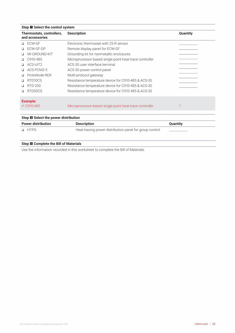
nVent.com | 53RAYCHEM-DG-H58139-RaySolMIFreFrostHeat-EN-1909
Step 7 Select the control system
Thermostats, controllers, and accessories
Description Quantity
ECW-GF ECW-GF-DP MI-GROUND-KIT C910-485 ACS-UIT2 ACS-PCM2-5 ProtoNode-RER RTD10CS RTD-200 RTD50CS
Electronic thermostat with 25-ft sensorRemote display panel for ECW-GFGrounding kit for nonmetallic enclosuresMicroprocessor-based single-point heat-trace controllerACS-30 user interface terminalACS-30 power control panelMulti-protocol gatewayResistance temperature device for C910-485 & ACS-30Resistance temperature device for C910-485 & ACS-30Resistance temperature device for C910-485 & ACS-30
________________________________________________________________________________________________________________________
Example: C910-485 Microprocessor-based single-point heat-trace controller 1
Step 8 Select the power distribution
Power distribution Description Quantity
HTPG Heat-tracing power distribution panel for group control ____________
Step 9 Complete the Bill of Materials
Use the information recorded in this worksheet to complete the Bill of Materials.

nVent.com | 54RAYCHEM-DG-H58139-RaySolMIFreFrostHeat-EN-1909
MI CABLES DIRECTLY EMBEDDED FREEZER FROST HEAVE PREVENTION DESIGN WORKSHEET
Step 1 Determine the freezer configuration
Determine freezer area (from scale drawing) Determine freezer operating temperature
Record insulation R-value
Supply voltage
Phase
x =Freezer area
(ft2/m2)Side A (length)
(ft/m) Side B (width)
(ft/m) ______________°F/°C_____________ ft2·°F·hr/Btu _____ Volts _____ Phase
Example:40 ft 20 ft 800 ft2
x =Freezer area (ft2)Side A (length)
(ft) Side B (width)
(ft) –30°FR-20 (20 ft2·°F·hr/Btu) 208 V
Single phase
Step 2 Determine the heat loss and freezer load
Based on the insulation R-value and freezer operating temperature you recorded in Step 1, use Table 11 to select the following:
Design power _______________W/ft2 (W/m2) Freezer load _______________W/ft2 (W/m2)
Example:
Step 3 Select the heating cable, layout and length
Use Table 12 and Table 13 to select your heating cable and determine your cable wattage.
Heating cable voltage 120 V 208 V 240 V 277 V 347 V
1.1 W/ft2
Example:
1.1 W/ft2
Design power Freezer load
Example:
Design power (W/ft2) / (W/m2)
x =Area (ft2/m2) Power required
(W)Catalog number Cable wattage
(W)Heated length
(ft)
Design power (W/ft2)
x =Area (ft2) Power required
(W)Catalog number Cable wattage
(W)Heated length
(ft)
208 V
1.1 W/ft2 800 ft2 880 W SUB19 885 W 245 ft
Quantity
Quantity
1

nVent.com | 55RAYCHEM-DG-H58139-RaySolMIFreFrostHeat-EN-1909
Step 4 Determine the heating cable spacing
Imperial Metric
Step 5 Determine the electrical parameters
Determine circuit breaker rating and number of circuitsCircuit breaker rating (A): _____________________________ Number of circuits: _____________________________
Calculate circuit breaker rating and number of circuits
Calculate total transformer load
Step 6 Select the accessories
Accessory Description Quantity
D1297TERM4 Cast aluminum junction box _____________
Example: D1297TERM4 Cast aluminum junction box 1
Example:
800 ft2 245 ft 39.2 in rounded to 39 in
Area (ft2)x 12 /
If necessary, round to whole number.
=Heated length (ft) Cable spacing (in)
Area (ft2)x 12 / =
Heated length (ft) Cable spacing (in)
Area (m2)x 100 / =
Heated length (m) Cable spacing (cm)
Example
Total current (A)
*Use next largest available circuit breaker or break into smaller circuits
*Use next largest available circuit breaker or break into smaller circuits
= = =x 1.25( )Minimum circuit breaker rating (A)* Circuit breaker rating (A) Number of circuits
Total current (A)= = =x 1.25( )
Minimum circuit breaker rating (A)* Circuit breaker rating (A) Number of circuits
4.3 A 5.4 A 15 A 1
Total transformer load (kW)Cable1 (W)+( )
Cable2 (W)+
CableN (W)Cable3 (W)...+ / 1000 =
Total transformer loadCable1
( ) / 1000 =885 W 0.9 kW
Example
Example
Total current (A)
*Use next largest available circuit breaker or break into smaller circuits
*Use next largest available circuit breaker or break into smaller circuits
= = =x 1.25( )Minimum circuit breaker rating (A)* Circuit breaker rating (A) Number of circuits
Total current (A)= = =x 1.25( )
Minimum circuit breaker rating (A)* Circuit breaker rating (A) Number of circuits
4.3 A 5.4 A 15 A 1
Total transformer load (kW)Cable1 (W)+( )
Cable2 (W)+
CableN (W)Cable3 (W)...+ / 1000 =
Total transformer loadCable1
( ) / 1000 =885 W 0.9 kW
Example

nVent.com | 56RAYCHEM-DG-H58139-RaySolMIFreFrostHeat-EN-1909
Step 7 Select the control system
Thermostats, controllers, and accessories
Description Quantity
ECW-GF ECW-GF-DP MI-GROUND-KIT C910-485 ACS-UIT2 ACS-PCM2-5 ProtoNode-RER RTD10CS RTD-200 RTD50CS
Electronic thermostat with 25-ft sensorRemote display panel for ECW-GFGrounding kit for nonmetallic enclosuresMicroprocessor-based single-point heat-trace controllerACS-30 user interface terminalACS-30 power control panelMulti-protocol gatewayResistance temperature device for C910-485 & ACS-30Resistance temperature device for C910-485 & ACS-30Resistance temperature device for C910-485 & ACS-30
________________________________________________________________________________________________________________________
Example: C910-485 Microprocessor-based single-point heat-trace controller 1
Step 8 Select the power distribution
Power distribution Description Quantity
HTPG Heat-tracing power distribution panel for group control _____________
Step 9 Complete the Bill of Materials
Use the information recorded in this worksheet to complete the Bill of Materials.

©2019 nVent. All nVent marks and logos are owned or licensed by nVent Services GmbH or its affiliates. All other trademarks are the property of their respective owners. nVent reserves the right to change specifications without notice.
Our powerful portfolio of brands:
CADDY ERICO HOFFMAN RAYCHEM SCHROFF TRACERnVent.com
RAYCHEM-DG-H58139-RaySolMIFreFrostHeat-EN-1909
North AmericaTel +1.800.545.6258Fax [email protected]
57