Embed Size (px)
Citation preview

FreeBee: Cross-technology Communicationvia Free Side-channel
Song Min Kim and Tian He
Department of Computer Science and Engineering, University of Minnesota, USA{ksong, tianhe}@cs.umn.edu
ABSTRACT
This paper presents FreeBee, which enables direct unicastas well as cross-technology/channel broadcast among threepopular wireless technologies: WiFi, ZigBee, and Bluetooth.Our design aims to shed the light on the opportunities thatcross-technology communication has to offer including, butnot limited to, cross-technology interference mitigation andcontext-aware smart operation. The key concept of FreeBeeis to modulate symbol messages by shifting the timing ofperiodic beacon frames already mandatory for wireless stan-dards without incurring extra traffic. Such a generic cross-technology design consumes zero additional bandwidth, al-lowing continuous broadcast to safely reach mobile and/orduty-cycled devices. A new interval multiplexing techniqueis proposed to enable concurrent broadcasts from multiplesenders or boost the transmission rate of a single sender.Theoretical and experimental exploration reveals that Free-Bee offers a reliable symbol delivery under a second andsupports mobility of 30mph and low duty-cycle operationsof under 5%.
Categories and Subject Descriptors
C.2.1 [Network Architecture and Design]: Wireless com-munications
Keywords
Wireless; Protocol; Cross-technology
1. INTRODUCTIONThe unprecedented proliferation of wireless devices in the
last decade has been led by multiple wireless technologies,each offering convenience in different aspects of our dailylives. However, wireless technologies are victims of theirown success: spectrum sharing among incompatible wirelesstechnologies has led to a severe wireless coexistence prob-lem [18, 28, 33, 38, 39, 42].This paper begins with the recognition that this coex-
istence is indeed double side: although it may cause inef-
Permission to make digital or hard copies of all or part of this work for personal or
classroom use is granted without fee provided that copies are not made or distributed
for profit or commercial advantage and that copies bear this notice and the full cita-
tion on the first page. Copyrights for components of this work owned by others than
ACM must be honored. Abstracting with credit is permitted. To copy otherwise, or re-
publish, to post on servers or to redistribute to lists, requires prior specific permission
and/or a fee. Request permissions from [email protected].
MobiCom’15, September 7–11, 2015, Paris, France.
c© 2015 ACM. ISBN 978-1-4503-3619-2/15/09 ...$15.00.
DOI: http://dx.doi.org/10.1145/2789168.2790098.
ficiency and unfairness in channel/spectrum utilization, italso provides new opportunities because the standards forindividual technologies are specialized and hence possessstrengths in different areas that are, often the weaknessesof the others. For example, while WiFi has access to a vir-tually unlimited amount of information via the Internet, itconsumes a considerable amount of power, causing batteryproblems in mobile devices [10, 16]. Conversely, the Zig-Bee network often operates as a stand-alone and has lim-ited information, but is extremely energy efficient. Thus,both networks can be enhanced via mutual supplementa-tion, demonstrating the positive side of coexistence.
In this paper, we propose FreeBee, a cross-technologycommunication framework that is generic and transparent(i.e., no extra traffic). Our design aims to mitigate thedetrimental effect of coexistence while exploring the oppor-tunities behind it. As such, FreeBee sheds the light on theopportunities that cross-technology communication has tooffer including, but not limited to, cross-technology interfer-ence mitigation and context-aware smart operation. Specif-ically we achieve this via embedding symbol into beaconsby shifting their transmission timing. Although the conceptof modulating via signal timings is known as PPM (PulsePosition Modulation), legacy PPM supports only commu-nication between homogeneous devices and requires precisepulse timing, which can be hardly satisfied in wireless coex-istence environments with mainly contention-based MACs.
Existing cross-technology communication works [14, 40]are technology-specific and require dedicated packets for com-munication, burdening already-crowded channels with fur-ther overhead. In contrast, Freebee utilizes mandatory bea-cons widely adopted among wireless technologies [5, 35, 36],achieving a generic and free-side-channel design. In sum-mary, our original contribution is three-fold:
• We propose FreeBee, a novel cross-technology commu-nication framework that allows direct communicationbetween heterogeneous senders and receivers. In addi-tion, FreeBee allows heterogeneous devices to receivebroadcast simultaneously from a sender with overlap-ping frequencies (e.g., Bluetooth to WiFi and ZigBee)and support a sender with a wider bandwidth (e.g.,WiFi) to reach multiple narrower-band receivers (e.g.,WiFi to multi-channel ZigBee).
• FreeBee requires no hardware modification and doesnot introduce dedicated traffic. Its existence is trans-parent to legacy wireless systems. Our new intervalmultiplexing scheme supports concurrent transmissionand reception of multiple signals.
317

• We present three prototype implementations: WiFi,ZigBee, and Bluetooth. Results suggest that FreeBeeoffers reliable symbol delivery within less than a sec-ond and supports mobility up to 30mph and duty cycleoperation of under 5%. We also demonstrate a prac-tical use of FreeBee: Inspecting real WiFi deploymentpatterns in a shopping mall area, FreeBee was foundto save 78.9% of the energy otherwise wasted by theWiFi interface.
The paper is organized as follows. Section 2 presents mo-tivations. The FreeBee design and features are introducedin Sections 3 and 4. Sections 5 and 6 evaluate performanceanalytically and empirically, followed by a FreeBee applica-tion in Section 7. We summarize related work in Section 8and conclude in Section 9.
2. MOTIVATIONThis section demonstrates a wide range of benefits the
FreeBee technology has to offer.
Figure 1: Context-aware home automation
• Benefit to ZigBee – Smart homes: FreeBee enablesdirect sharing of information without assistance from costly(>150 USD) dual-radio gateways that are mostly unavail-able in real-life settings. One such type of information isuser presence, which is accessible by WiFi AP by observingthe nodes associated to it. Sharing this information enablesother networks to provide context-aware service. Figure 1demonstrates the example of a smart home with ZigBee-assisted appliances. HomeWiFi AP first determines whetherthe resident is away or home (i.e., his/her smart phone is as-sociated or not). Using FreeBee, this information is broad-cast from the AP to all the ZigBee nodes inside the home todrive them to the appropriate operation mode. For instance,once the resident leaves they turn to “away mode”, such aslowering home temperature to an energy-economic value.
Figure 2: Wake on selective WLAN
• Benefit to WiFi – Mobile devices: Operating a WiFiNetwork Interface Card (NIC) continuously depletes pre-cious energy in portable devices [10, 16]. To tackle this,ZiFi [43] suggests attaching a low-power ZigBee radio to thedevice to wake up the WiFi NIC whenever it detects the exis-tence of any WiFi AP. While this approach can significantly
reduce standby energy, we believe that further savings canbe achieved.
Nowadays most of metropolitan areas are overloaded withWiFi APs, many of which are private. Thus, it is still awaste of energy to blindly wake up a WiFi NIC when anarbitrary AP shows up, without knowing if it is accessibleor not. As shown in Figure 2, we avoid this issue by embed-ding 1-bit accessibility information (i.e., open/private) intoWiFi beacons and allowing the attached low-power radio(Bluetooth or ZigBee) to capture this information throughFreeBee. Accordingly, the WiFi NIC can wake up only whenit finds an open AP. We refer to this function as wake on se-lective WLAN. We note that this approach can be extendedto limiting WiFi wakeup only to discovering an AP that fitsthe user’s interest; for instance, when there is an AP thatmatches a user-defined SSID.
Figure 3: Real-time patient monitoring
• Benefit to Bluetooth – Health care: Taking advan-tage of its low-power operation, Bluetooth technology iswidely used in portable medical devices, including glucoseand heart monitors [13]. Although FreeBee is not designedto transfer a large volume of medical data, it enables healthalerts by embedding urgent information into Bluetooth bea-cons. The ubiquitous WiFi coverage in most indoor en-vironments today provides a continuous alert service evenif patients are away from their Bluetooth-enabled medicalstation, as shown in Figure 3. This figure also shows thatFreeBee can offer the location of the patient via geolocationprovided by WiFi AP, allowing accurate and timely medicalactions in case of an emergency.
Figure 4: Cross-technology coordination
• Benefit to all – Channel efficiency: All WiFi, Zig-Bee, and Bluetooth networks can benefit from FreeBee viacross-technology channel coordination. As a result of evolv-ing separately without considering each other, channel ac-cess schemes in heterogeneous wireless technologies are in-compatible, leading to a severe CTI [20, 25, 40, 41]. Thiscross-technology channel access problem can be addressedby allowing explicit communication among different tech-nologies. As demonstrated in Figure 4, FreeBee essentiallyallows TDMA or FDMA among heterogeneous wireless plat-forms, alleviating CTI. For instance, FreeBee realizes mecha-nisms similar to NAV (Network allocation vector) or RTS/CTSin WiFi for spectrum allocation that is global across tech-nologies.
318
3. FRAMEWORK DESIGNThis section presents an overview of FreeBee, followed by
design specifics such as modulation and demodulation tech-niques. Without loss of generality, we use communicationbetween WiFi (sender) and ZigBee (receiver) to illustratethe generic design of FreeBee.
3.1 Design OverviewWe propose a cross-technology communication framework
in which symbols are embedded into the timing of beaconframes. Specifically, we slightly shift the transmission time(advance or delay) of beacon frames, a configurable settingin most WiFi APs deployed today, simply via HTTP pro-tocol. The shift is made in the units of 1.024ms, compli-ant to the 802.11 standard unit used in beacon scheduling,known as TBTT (Target Beacon Transmission Time) [35].To ensure a free side-channel operation, FreeBee shifts tim-ing in such a way that the average interval remains the sameas the original setting. Thus, the proposed communicationframework is not only transparent, but also does not con-sume additional bandwidth or energy. This unique aspectenables important information to be broadcast continuously,safely reaching mobile and/or duty-cycled ZigBee receiverswhose presence or active periods are a priori unknown to thesender.However, WiFi beacons cannot be directly captured and
recognized by ZigBee nodes, due to incompatible PHY lay-ers. Instead, as WiFi coexists with ZigBee on the 2.4GHzISM band, a ZigBee receiver statically detects the positionof the WiFi beacons in the wireless channel, using its RSSIsensing capability. We note that, as a foundational func-tion for MAC techniques including CSMA, RSSI samplingis common among varieties of wireless standards (e.g., Blue-tooth).
FreeBee Multiple Access
FreeBee Modulator
IEEE 802.11 MAC/PHY
FreeBee Demodulator
IEEE 802.15.4 RSSI Sampler
Sender Receiver
FreeBee Multiple Access
Figure 5: Architecture and scope in white boxes
Figure 5 depicts the overall architecture and the scopeof this paper. Our design spans modulation/demodulationtechniques, as well as a multiple access scheme for con-current communications. We note that the WiFi-ZigBeeFreeBee design is based on 802.11 and 802.15.4 standards,and our design is compatible with all 802.11 variants (i.e.,a/b/g/n) and 802.15.4-compliant nodes (e.g., TelosB andMICAz) and requires no hardware modification. In fact,FreeBee can be adopted to enable communication betweenany heterogeneous wireless platforms as long as the channelis shared. In the following, we first propose a basic versionof FreeBee with the simplest form, followed by elaborateddesigns that enhance the basic version.
3.2 Basic FreeBeeIn this section, we describe the basic version of modula-
tion/demodulation we refer to as FreeBee. This design as-sumes that the unmodulated position of the beacon is found
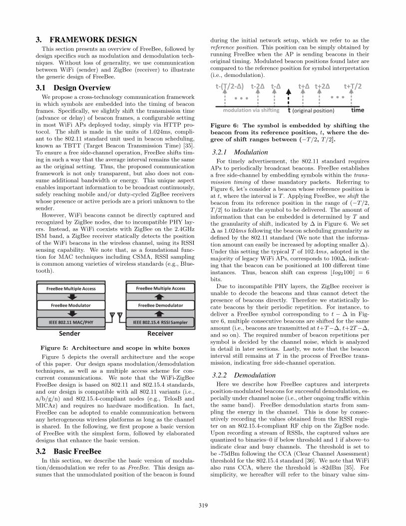
during the initial network setup, which we refer to as thereference position. This position can be simply obtained byrunning FreeBee when the AP is sending beacons in theiroriginal timing. Modulated beacon positions found later arecompared to the reference position for symbol interpretation(i.e., demodulation).
t (original position)
t+∆ t+2∆ t+T/2 t-2∆ t-∆ t-(T/2-∆)
timemodulation via shifting
Figure 6: The symbol is embedded by shifting thebeacon from its reference position, t, where the de-gree of shift ranges between (−T/2, T/2].
3.2.1 Modulation
For timely advertisement, the 802.11 standard requiresAPs to periodically broadcast beacons. FreeBee establishesa free side-channel by embedding symbols within the trans-mission timing of these mandatory packets. Referring toFigure 6, let’s consider a beacon whose reference position isat t, where the interval is T . Applying FreeBee, we shift thebeacon from its reference position in the range of (−T/2,T/2] to indicate the symbol to be delivered. The amount ofinformation that can be embedded is determined by T andthe granularity of shift, indicated by ∆ in Figure 6. We set∆ as 1.024ms following the beacon scheduling granularity asdefined by the 802.11 standard (We note that the informa-tion amount can easily be increased by adopting smaller ∆).Under this setting the typical T of 102.4ms, adopted in themajority of legacy WiFi APs, corresponds to 100∆, indicat-ing that the beacon can be positioned at 100 different timeinstances. Thus, beacon shift can express ⌊log2100⌋ = 6bits.
Due to incompatible PHY layers, the ZigBee receiver isunable to decode the beacons and thus cannot detect thepresence of beacons directly. Therefore we statistically lo-cate beacons by their periodic repetition. For instance, todeliver a FreeBee symbol corresponding to t − ∆ in Fig-ure 6, multiple consecutive beacons are shifted for the sameamount (i.e., beacons are transmitted at t+T−∆, t+2T−∆,and so on). The required number of beacon repetitions persymbol is decided by the channel noise, which is analyzedin detail in later sections. Lastly, we note that the beaconinterval still remains at T in the process of FreeBee trans-mission, indicating free side-channel operation.
3.2.2 Demodulation
Here we describe how FreeBee captures and interpretsposition-modulated beacons for successful demodulation, es-pecially under channel noise (i.e., other ongoing traffic withinthe same band). FreeBee demodulation starts from sam-pling the energy in the channel. This is done by consec-utively recording the values obtained from the RSSI regis-ter on an 802.15.4-compliant RF chip on the ZigBee node.Upon recording a stream of RSSIs, the captured values arequantized to binaries–0 if below threshold and 1 if above–toindicate clear and busy channels. The threshold is set tobe -75dBm following the CCA (Clear Channel Assessment)threshold for the 802.15.4 standard [36]. We note that WiFialso runs CCA, where the threshold is -82dBm [35]. Forsimplicity, we hereafter will refer to the binary value sim-
319

ply as RSSI. Furthermore, as a RSSI sample in ZigBee is ameasurement spanning for 128us, the sampling rate is set tobe 1/128us = 7.8KHz to avoid time gaps between sampleswhile keeping the rate at its minimum.
10 0 0 01 1 0 11 0 1 01 0 0 1 0 1 0
10 0 0
0
1
1 0 11
0 1 01 0
0 1 0 1 0
t1 t2 t3 t20t19
Fold sum: 0 4 1 2 2
Figure 7: Folding example: series of RSSI samplesexpressed as boxes. Both black and gray indicate abusy channel where the former is a periodic beaconsignal with λ = 5, while the latter is random noiseinduced by traffic or interference. White representsan idle channel. By folding the series into a matrixwith P = 5 (= λ), the black boxes align column-wise.
We then apply folding to the obtained RSSI vector, a sig-nal processing technique that allows detecting periodic sig-nal under noise. We note that this technique was originallyintroduced in [34] and was recently featured by ZiFi [43] todetect the presence of WiFi AP. Given a sampled RSSI vec-tor, folding by P simply cuts the vector into sub-vectors ofequal lengths of P and stacks them to yield a matrix. Anexample of folding is shown in Figure 7, where a sampledRSSI vector of length 20 is considered. Let the interval ofthe beacons captured in the vector be T seconds, and thenumber of samples in T as λ In the example λ = 5, andupon folding by P = λ, RSSIs of beacons (in black) alignin a column. the column-wise sum is referred to as the foldsum, where the column with the highest fold sum indicatesthe position of the beacon. Note that the fold sums arelikely to be smaller in other columns, as they are inducedby either random (thus aperiodic) traffic or beacons withdifferent intervals.
noise
beacon
(a) Reference Position
Reference
Position
20
(b) Modulated Position
Figure 8: Example of FreeBee demodulation in prac-tice, when T = 113∆ = 115.7ms and λ = 904
Figure 8 presents an example of demodulating FreeBeesymbol (20∆) in practice. To sum up, FreeBee demodula-tion is process of finding the column corresponding to beaconposition, which can easily be achieved by folding and simplypicking the column with the maximum fold sum. This sameprocess is used to learn the reference position of the bea-con during network initialization and to find the modulatedposition. The difference of the two positions indicates the
symbol within. Other harmonic analysis techniques, such asFFT (Fast Fourier Transform) and autocorrelation, do notyield the position (i.e., phase) of the beacon, and hence arenot suitable for our purpose.
t+(T-∆)
timet t+2T
t+(3T-∆)
t+4T
t+(5T-∆)
Figure 9: A-FreeBee: the positions of every other
beacons are shifted (in gray), whereas the degree ofshift is ∆ in the example.
3.3 Enhanced Feature #1: AsynchronyThe basic FreeBee design embeds the symbol as a bea-
con time shift from the reference position, a concept thatrequires learning the position beforehand. We relax thiscondition to introduce A-FreeBee (Asynchronous FreeBee),freeing our design from any prior knowledge to offer instan-taneous communication.
Figure 9 shows Modulation of A-FreeBee. Applying A-FreeBee to beacons with an interval of T , beacons are sched-uled to construct two streams of beacons (black and gray)with the same interval of 2T , where one stream (i.e., graybeacons) is a shifted version of the other (i.e., black bea-cons). This is achieved by shifting every other beacon by theamount that corresponds to the symbol to be delivered. Thefigure demonstrates a case where the symbol corresponds to∆, indicating one unit of shift. We note that A-FreeBeeis also a free-side-channel, as the average interval betweenconsecutive beacons is still T .
Under A-FreeBee design, the reference position is no longerrequired; it simply looks for two beacon streams with thesame period by folding with P = 2λ. The embedded sym-bol is interpreted directly from the phase difference, i.e.,Two columns with the first and second highest fold sumsare found, where the distance between them indicates A-FreeBee symbol. A demodulation example of A-FreeBee is
1 1 10 1 0 1 0
1 1 10 1 0
1 0 11 0 0
1 0 11 0 0 0 1
1
0
0
1
(2λ samples)
t1 t2 t3
Fold sum: 2 1 1 2 1 0 1 1
t16t15
Figure 10: Folding example for A-FreeBee: two highfold sum columns are detected via folding.
shown in Figure 10 for a RSSI vector of length 16. Twobeacon streams are depicted in black boxes, and the grayboxes represent noise. Two columns with high fold sumsare found by folding with P = 2λ = 8, where the distancebetween the two columns is T −∆. Noting that the distancewould simply be T before modulation, the amount of shift(i.e., the symbol) is therefore ∆. Figure 11 below demon-strates A-FreeBee demodulation in practice, where the con-veyed symbol is 20∆.
The asynchronous version features several advantages overthe basic FreeBee, including that it (i) requires no synchro-
320

T-20
noise
Figure 11: A-FreeBee demodulation (T = 113∆)
nization, (ii) is robust to clock drifts, and (iii) supports in-stantaneous communication without prior knowledge. Wenote that all these improvements come with a trade-off indata rate; A-FreeBee, compared to the basic FreeBee, re-quires collecting a higher number of beacons to form twohigh fold sums instead of one. The relationship between theperformances of FreeBee and A-FreeBee are analyzed boththeoretically and empirically in later parts of the paper.
3.4 Enhanced Feature #2: ConcurrencyIn the face of multiple (A-)FreeBee senders, selecting the
same or arbitrary intervals may lead the signals to tangle andcause errors in demodulation. In this section, we address thisissue to allow simultaneous transmissions of an arbitrarynumber of (A-)FreeBee symbols such that each of them canbe safely demodulated at the receiver.
1 0 0 1 0 0 1 0 0
0 0 1 0 0 0 0 1 0
1 0 1 1 0 0 1 1 0
1 0 1
1 0 0
1 1 0
1 0 1 1 0
0 1 1 0 1
FreeBee #1
FreeBee #2
Merged Signal
ZigBee Receiver
Folding, P=3
Folding, P=5
Figure 12: Demodulating interval-mutiplexed Free-Bee symbols.
3.4.1 Interval Multiplexing
Recall that, according to the 802.11 standard, beacon in-tervals are defined in the unit of ∆(=1.024ms). Let beaconintervals of n neighboring APs be x1∆, x2∆, ..., xn∆. Then,FreeBee allows simultaneous communication of n APs if x1,x2, ... xn are pair-wise co-primes. We refer to this as intervalmultiplexing.Figure 12 demonstrates a scenario of interval multiplex-
ing/demultiplexing, where two FreeBee senders with inter-vals T1 = 3∆ (in black) and T2 = 5∆ (in gray) introduce avector of merged RSSI signals at a receiver, and this receiverutilizes interval de-multiplexing to demodulate. Specifically,by folding with P = 3 and 5 and looking for the column withthe highest fold sum, the receiver can detect the position ofthe beacons as if the other signal does not exist. This isbecause 3 and 5 are co-primes, and no longer holds whenthey are not; for example, consider a sampled RSSI vectorincluding beacons with intervals T1 = 2∆ and T2 = 4∆.When folded by P = 4, both beacons will form high foldsums, causing demodulation error. We note that while thefigure shows only two senders for clarity, this idea can beextended to n senders as long as the intervals are pairwiseco-prime. The rationale behind this scheme is given in thefollowing proposition:
Proposition 3.1. For FreeBee signals with co-prime in-tervals, folding for one signal restricts the fold sum of theothers to a maximum of 1.
Proof. Let T1 = x1∆ and T2 = x2∆ be two beaconintervals where x1 and x2 are co-primes. When a sampledRSSI vector containing beacons of interval T2 is fold by P =x1, beacon repeats in a column every LCM (least commonmultiple) of x1 and x2, which is x1 × x2. Since the totallength of the sampled RSSI vector is much smaller thanx1 × x2, beacons with the interval of x1∆ cannot be foldedinto the same column when folded by x2 (and vice versa),yielding the maximum fold sum of 1.
The proposition states that the cross-interference betweenFreeBee signals is effectively suppressed when intervals areco-prime, essentially granting orthogonality between signalsfor concurrent communication. We note that this holds forboth basic FreeBee and A-FreeBee.
In practice, to avoid the overhead in computing for co-prime numbers, we allow APs to select among a set of pre-stored prime numbers instead. Moreover, the same intervalshould not be chosen among neighboring APs, which can beeasily achieved in listen before talk fashion; they listen toeach other to acquire the beacon interval information (i.e.,x in T = x∆) that, according to the 802.11 standard, isrecorded within beacons. After storing a set of intervalsused by the neighboring APs, an unoccupied prime numberis chosen as its interval. Conversely, coordination via wiredconnection (i.e., WLAN or the Internet) may be preferred,which avoids the hidden terminal problem.
3.4.2 Implicit Addressing Feature of FreeBee
This section discusses the unique addressing scheme usedin FreeBee. As a reminder, demodulating each interval-multiplexed FreeBee signals remains the same as the casefor a single signal; folding with P yields the correspondingFreeBee signal with P .
FreeBee #1
P=3
FreeBee #2
P=5
2Receiver #1
Receiver #2
FreeBee #3
P=7
3
Listening to FreeBee #1 (P=3)
Listening to FreeBee #2, 3 (P=5, 7)
Figure 13: Implicit addressing via interval multi-plexing
• For stationary deployment: As shown in Figure 13,each interval P is allocated to one freeBee sender, implicitlyaddressing that sender. Hence a receiver may select a subsetof P ’s that corresponds to the sender(s) of interest.• For mobile deployment: In mobile scenarios, mobiledevices are not aware of P s used by nearby FreeBee enableddevices. We need to fold for all P s in the prime set to receivefrom every sender. This is not as computationally heavy asit may sound, as the number of primes, by the prime numbertheorem [21], is limited to xmax
ln(xmax)− xmin
ln(xmin)when xmax and
xmin are the maximum and minimum values in the primeset. For example, there are 20 primes in the interval rangeof xmin = 53 and xmax = 149.
321

From a practical point of view, we emphasize that implicitaddressing is a unique and effective feature of our design: aseach sender is required to select different beacon interval,symbols demodulated with the same P are ensured to befrom the same sender. This allows safely constructing along symbol by appending received symbols. However, thisis not the case for all other cross-technology techniques. InEsense [14] and HoWiES [41], a sender ID has to be embed-ded along with information in order to concatenate separatesymbols correctly, leading to a large overhead in such a low-rate cross-technology communication.
4. PRACTICAL ISSUESIn this section, we discuss practical issues and their effects
on our design.• Channel access delay: Although beacons are prioritizedover data packets and hence queueing delays are negligi-ble [35], they do suffer from channel access delays accordingto CSMA. This is in fact a challenge uniquely imposed onour design, which is different from traditional the PPM en-vironment where all pulses are transmitted at their exacttimes. Upon long delays, a beacon may fail to contribute tofolding. This is precisely why beacon repetitions are needed(e.g., four beacons in Figure 7) for statistical performanceguarantee. Our empirical study in Section 6.3 suggests that5 beacons yield an error of less than 1%.• Noise: Any non-beacon signal occupying the spectrumserves as noise and is a potential source of error. That is, asfrequent 1’s due to noise fill up the sampled RSSI, there isan increased chance of a large fold sum formed elsewhere tothe beacon position, thus inducing demodulation failure. Inother words, the performance of our design is enhanced byreducing the noise. This is simply done by taking only thefirst two RSSI samples for any packet including beacons anddiscarding (i.e., set to 0) the rest. The reason behind thisapproach is two-fold: (i) As data packets tend to be muchlonger than beacons, this reduces noise to 1/6 on average inour experiments. (ii) Our empirical analysis indicates thatthe channel access delays of beacons are mostly (>90%) lessthan 256us, where a similar result was reported in a recentstudy [19]. Noting that the duration of a RSSI sample is128us, this suggests the first two RSSI samples (256us) ofbeacons maintain a high chance of overlapping (i.e., con-tributing to fold sum) upon folding.
5. ANALYTICSIn this section, we provide a theoretical analysis of the
performance of FreeBee and A-FreeBee.
5.1 SER vs. Sampling DurationAs noted earlier, the symbol error occurs upon demodula-
tion failure, essentially when the fold sum of noise is higherthan that of the beacons. For brevity, we defer a detailedSER (Symbol Error Rate) derivation to Appendix 9 andhere move directly to the results to demonstrate the impactof three system parameters: (i) T , the beacon interval. (i)ρ, the number of beacon repetitions for statistical demod-ulation; and (iii) Sampling duration, the sampling time toobtain a symbol, which is ρ× T for FreeBee and ρ× 2T forA-FreeBee.Figures 14(a) and 14(b) show Symbol Error Rate (SER)
when default beacon interval is set as T = 97∆ = 99.3ms.
0.2 0.4 0.6 0.8 1 1.2 1.40
5
10
15
20
Sampling Duration (s)
Sy
mb
ol
Err
or
Ra
te (
%)
B=5%
B=15%
B=30%
B=60%
B=90%
(a) FreeBee
0.4 0.8 1.2 1.6 2 2.40
5
10
15
20
Sampling Duration (s)
Sy
mb
ol
Err
or
Ra
te (
%)
B=5%
B=15%
B=30%
B=60%
B=90%
(b) A-FreeBee
Figure 14: SER vs. sampling duration (T = 97∆).
These figures convey three ideas: (i) longer sampling (i.e.,higher ρ) lowers SER, as more beacons are utilized to fightagainst noise; (ii) for a given duration, FreeBee achieves alower SER than A-FreeBee; and (iii) higher channel occu-pancy, denoted by B, indicates more noise, thus higher SER.The figures have B up to 90% for completeness of analysis,where B ≤ 30% was observed in our experiment (under thethreshold of -75dBm) in a university building with 50+ APs.Similar observations were reported in a recent study from alarge-scale open WiFi trace [3, 43]. The figures suggest an-alytically that FreeBee and A-FreeBee achieve SER<1% fordurations of 0.7s and 1.2s under such condition. We notethis analytical result matches well with results from empir-ical experiments shown in Section 6.3.
50 70 90 110 130 1500
10
20
30
40
50
60
Beacon Interval (ms)
Bit
Rate
(b
ps)
ρ=2 ρ=3 ρ=4 ρ=5 ρ=6
Figure 15: Bit rate vs. T for different ρ.
5.2 Transmission Rate vs. Beacon IntervalBeacon interval, T , is another factor that can affect (A-
)FreeBee performance. The impact of beacon interval Tcan be observed with bit rate R. Intuitively, enlarging thebeacon interval has two effects: (i) it offers more space forshift, or equivalently, yields more bits per symbol; and (ii)it requires more time to reach the same ρ. The bit rate forFreeBee can be computed as below:
R =log2T/∆
T × ρbps (1)
Noting that ∆ (1.024ms in WiFi) defines the granularity ofshift, the numerator in the Equ. 1 implies bit per symbol.Figure 15 shows the impact of beacon interval T on R indifferent scenarios for the range of practical intervals. InA-FreeBee, the rate is cut in half as it takes double sam-ple duration (i.e., ρ × 2T ) to convey a same symbol. It isimportant to note that the rate given here is per sender,without bandwidth consumption (i.e., without incurring ex-tra traffic). Due to interval multiplexing, the aggregatedthroughput linearly increases according to the number ofsenders. Furthermore, boosting the throughput of a single
322

sender by adopting additional beacons is also a viable option.Performances under such cases are shown via experimentalevaluations in the next section.
6. PERFORMANCE EVALUATIONWe show the generality of (A-)FreeBee by evaluations per-
formed across four platforms operating on three differentwireless standards: WiFi, ZigBee, and Bluetooth.
(a) WiFi(WARP) (b) WiFi(laptop)
(c) ZigBee (d) Bluetooth
Figure 16: Four evaluation platforms on three dif-ferent wireless technologies – WiFi, ZigBee, andBluetooth.
Table 1: Experiment SettingsCommunication Tx Tx Rx
Direction Ch. Power Ch. Dist.
WiFi → ZigBee 1,4 13 dBm 11-15 8mZigBee → WiFi 11-14 0 dBm 1 1.5m
Bluetooth → WiFi 37-39 4 dBm 4 3mBluetooth → ZigBee 37-39 4 dBm 15 3m
6.1 Experiment SettingsThe experiment parameters are specified in Table 1, where
the detailed settings are as follows.
• Design generality: As a generic cross-technology com-munication framework, our design mechanisms including mo-dulation, demodulation, and interval multiplexing commonlyapply to different underlying technologies. This is possiblebecause, according to the standards, (i) beacons are adoptedin all three technologies of WiFi, ZigBee, and Bluetooth, (ii)they commonly allow modification of beacon timings, (iii)they reside on overlapping frequencies in the 2.4GHz bandand finally, (iv) the light-weight design makes our designfeasible even to low-end devices, as demonstrated later inthe section.
• WiFi: Figures 16(a) and 16(b) show the two WiFi plat-forms on which our design is implemented: WARP [9] andlaptops. The former is a wireless research platform fully inte-grated with WiFi PHY/MAC layers. As a FPGA-based sys-tem allowing real-time operation, the evaluation on WARPenables precise exploration into FreeBee performance. Fur-ther implementation on six different laptops with various
WiFi NICs from Qualcomm, Realtek, and Intel avoids hard-ware bias.
Evaluations via laptops utilize Lorcon2 packet injectionlibrary [7] to schedule beacons according to FreeBee, whichis a reasonable approach since laptops/PCs running soft-ware AP are frequently used in practice [4]. In Table 1,we use WiFi channel 1 (unless otherwise specified) for com-munication with ZigBee, one of the three most commonlyused channels (i.e., 1, 6, and 11), granting generality to ourresult. We then tune to channel 4, which overlaps with aBluetooth advertising channel (i.e., 38), for communicationwith Bluetooth.
• ZigBee: We use 30 ZigBee-compliant MICAz nodes (Fig-ure 16(c)) for our experiments. When operating as a re-ceiver, a MICAz node captures RSSI values (at 7.8KHz sam-pling rate by default) and records them within its 512KBon-board flash. The values are either processed (i.e., de-modulated) within the node or flushed to a PC for analysis,depending on experiments. We use channels 11-15, overlap-ping with WiFi channels 1 and 4, and a Bluetooth advertis-ing channel of 38.
• Bluetooth: Our design is implemented on IOGEAR Blue-tooth LE USB adapter, a cheap (∼12 USD) off-the-shelfproduct, shown in Figure 16(d). On this device, we utilizeAltBeacon [1] library running under Linux’s BlueZ driverfor FreeBee embedding. Specifically, connectable directedadvertising was used to generate FreeBee-enabled beaconson all three advertising channels of 37-39, which complies tothe standard on Bluetooth beaconing.
Figure 17: Per-sender throughputs achievable with-out incurring any extra traffic, evaluated on fourdifferent communication channels
6.2 Per-sender ThroughputIn this section we demonstrate the data rate achievable per
sender, under free side-channel as well as when the channelis fully utilized.• Free side-channel throughput: Figure 17 illustratesper-sender data rate without introducing additional traffic(i.e., free side-channel). The experiment was conducted ina residential area with 20+ APs in proximity. Beacon in-tervals are set as 99.3, 76.8, and 78.75ms for WiFi, Zig-Bee, and Bluetooth, respectively, where the rate may eas-ily be enhanced with shorter beacon intervals. The figuredemonstrates two ideas: (i) The performance of A-FreeBeeis slightly less than half of that of FreeBee, due to doubledsampling duration in A-FreeBee. Longer sampling durationincreases the chance of larger fold sum of noise, hence yieldshigher SER in A-Freebee compared to FreeBee. This agreeswith our theoretical analysis in Section 5.1. (ii) Among dif-ferent communication directions, WiFi to ZigBee exhibitsthe fastest rate of 31.5bps for FreeBee. The rate drops to
323

0.3 0.4 0.5 0.6 0.7 0.8 0.9 10
1
2
3
4
5
Sampling Duration (s)
Sym
bo
l E
rro
r R
ate
(%
)
Indoor
Outdoor
(a) FreeBee
0.6 0.8 1 1.2 1.4 1.6 1.8 20
2
4
6
8
10
Sampling Duration (s)
Sy
mb
ol
Err
or
Ra
te (
%)
Indoor
Outdoor
(b) A-FreeBee
100010 100011 100100
Constellation
......
Demodulation
success> 99%
(c) Constellation diagram and distribution
Figure 18: Indoor and outdoor performances of (a)FreeBee and (b)A-FreeBee when T = 97∆ = 99.3ms. Dueto less noise outdoors, both FreeBee and A-FreeBee reach SER<1% at ρ = 4, whereas indoor environmentrequired ρ = 5. (c) shows where the received symbols are positioned when ‘100011’ was sent 2,500 times.
14.6bps for ZigBee to WiFi as the ZigBee standard enforceslarge unit shift (i.e., ∆=15.36ms), reducing the amount of in-formation embedded in a symbol. While the Bluetooth stan-dard defines a fine-grained beacon shift unit (∆ = 0.625ms),the random backoff ranging up to 10ms affects the perfor-mances of Bluetooth to WiFi and ZigBee communicationswhere they show 17.5 and 17.8bps, respectively. While dis-abling the backoff functionality would increase the through-put significantly, the case is not considered in this paper as itrequires modification to the standard (lacks compatibility).• Upper bound throughput under ideal conditions:We demonstrate the effectiveness of our design by com-paring the maximum throughput of our design to that ofEsense [14], a state-of-art cross-technology communicationscheme. Esense, as a WiFi to ZigBee communication tech-nique, conveys data by modulating WiFi packet durations,where its ideal maximum throughput is reported under theideal condition of interference-free channel that is fully uti-lized by a single sender. Hence we adopt this setting inevaluating FreeBee. Evaluation parameters also follow thevalues proposed in Esense; That is, RSSI sampling rate of32KHz (= sampling interval of 30.5us), inter-frame dura-tion of 90us, and the maximum WiFi transmission rate of54Mbps (802.11g).To obtain the ideal FreeBee performance, we first note
that beacons need not be repeatedly transmitted under theinterference-free channel. That is, a single beacon frame con-veys a symbol where SER=0. When the maximum shift isx∆, a symbol (i.e., a beacon) embeds log2(x+1)bits, wherethe time it consumes consists of inter-frame duration, bea-con transmission time, and the amount of shift, where theunit of shift may be as small as the sampling interval (i.e.,∆ = 30.5us). When x = 4, FreeBee yields the through-put of 10.2Kbps given the beacon length of 100Bytes. Es-ense, according to its researchers, achieves the throughputof 5.13Kbps under the same setting. This is because Es-ense requires to use long-length packets (with long air-time)up to 1,500Bytes to enable measurement of WiFi packetdurations via a low-end ZigBee node. Meanwhile, FreeBeeutilizes short beacons to offer higher channel efficiency.
6.3 Symbol Error RateHere we present the reliability of our design in practice
by evaluating SER under both indoor and outdoor environ-ments in a residential area. This experiment is based onWiFi(WARP) to ZigBee communication, where more than2,500 symbols are sent and demodulated for SER computa-tion. The results for FreeBee and A-FreeBee are depicted in
Figures 18(a) and 18(b). Both designs reach SER ≤ 0.5%when ρ = 5 (i.e., 0.5s and 1s for FreeBee and A-FreeBee),regardless of the environment. Furthermore, both designsperform better in outdoor environments, due to lower chan-nel occupancy, B.
The lower figure in 18(c) illustrates the constellation, alongwith the demodulated positions of received symbols, whenthe 6bit symbol of ‘100011’ is repeatedly sent 2,500 times.Demodulation is successful when a dot resides inside the re-gion marked by gray dotted lines in the constellation. Theupper figure in 18(c) shows the distribution of the dots, inwhich >99% are successfully demodulated.
6.4 Cross-technology/channel BroadcastThis section demonstrates FreeBee’s unique capability to
broadcast to receivers with heterogeneous technologies andchannels.
Bluetooth
ZigBee
WiFi
Figure 19: Simultaneous broadcast from Bluetoothto WiFi and ZigBee.
• Cross-technology broadcast: Depicted in Figure 19, asa generic communication framework, FreeBee allows broad-cast to heterogeneous receivers with overlapping frequencies.Our generic design is effective in practice, since it avoids thecomplexity associated with technology-specific operation. Inthe experiment, WiFi and ZigBee were set to channels 4 and15 to listen to Bluetooth’s advertisement channel of 38 si-multaneously. In this particular case shown in Figure 19,WiFi receiver, compared to ZigBee, suffers from larger SER.It is due to higher noise, as WiFi channel 4 overlaps withthe popular WiFi channels of 1 and 6, while ZigBee channel15 does not.
WiFi
(Ch 4)ZigBee
(Ch15)
ZigBee
(Ch14)
Figure 20: Simultaneous broadcast from WiFi toZigBees on different channels.
324
F1
ON
F1-F2
ON
F1-F3
ON
F1-F4
ON
F1-F5
ON
(a) FreeBee
F1
ON
F1-F2
ON
F1-F3
ON
F1-F4
ON
F1-F5
ON
All
OFF
(b) WiFi
F1
ONF1-F2
ON
F1-F3
ON
F1-F4
ON
F1-F5
ON
All
OFF
(c) ZigBee
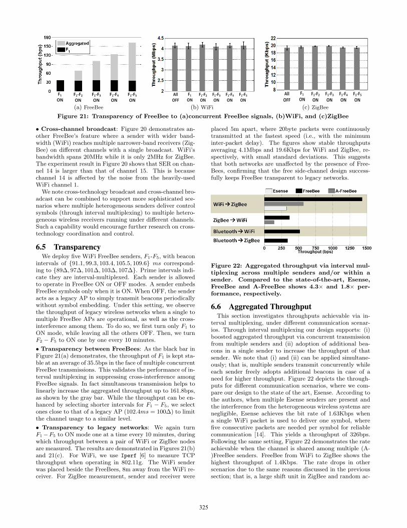
Figure 21: Transparency of FreeBee to (a)concurrent FreeBee signals, (b)WiFi, and (c)ZigBee
• Cross-channel broadcast: Figure 20 demonstrates an-other FreeBee’s feature where a sender with wider band-width (WiFi) reaches multiple narrower-band receivers (Zig-Bee) on different channels with a single broadcast. WiFi’sbandwidth spans 20MHz while it is only 2MHz for ZigBee.The experiment result in Figure 20 shows that SER on chan-nel 14 is larger than that of channel 15. This is becausechannel 14 is affected by the noise from the heavily-usedWiFi channel 1.We note cross-technology broadcast and cross-channel bro-
adcast can be combined to support more sophisticated sce-narios where multiple heterogeneous senders deliver controlsymbols (through interval multiplexing) to multiple hetero-geneous wireless receivers running under different channels.Such a capability would encourage further research on cross-technology coordination and control.
6.5 TransparencyWe deploy five WiFi FreeBee senders, F1-F5, with beacon
intervals of {91.1, 99.3, 103.4, 105.5, 109.6} ms correspond-ing to {89∆, 97∆, 101∆, 103∆, 107∆}. Prime intervals indi-cate they are interval-multiplexed. Each sender is allowedto operate in FreeBee ON or OFF modes. A sender embedsFreeBee symbols only when it is ON. When OFF, the senderacts as a legacy AP to simply transmit beacons periodicallywithout symbol embedding. Under this setting, we observethe throughput of legacy wireless networks when a single tomultiple FreeBee APs are operational, as well as the cross-interference among them. To do so, we first turn only F1 toON mode, while leaving all the others OFF. Then, we turnF2 − F5 to ON one by one every 10 minutes.
• Transparency between FreeBees: As the black bar inFigure 21(a) demonstrates, the throughput of F1 is kept sta-ble at an average of 35.5bps in the face of multiple concurrentFreeBee transmissions. This validates the performance of in-terval multiplexing in suppressing cross-interference amongFreeBee signals. In fact simultaneous transmission helps tolinearly increase the aggregated throughput up to 161.8bps,as shown by the gray bar. While the throughput can be en-hanced by selecting shorter intervals for F1 − F5, we selectones close to that of a legacy AP (102.4ms = 100∆) to limitthe channel usage to a similar level.
• Transparency to legacy networks: We again turnF1−F5 to ON mode one at a time every 10 minutes, duringwhich throughput between a pair of WiFi or ZigBee nodesare measured. The results are demonstrated in Figures 21(b)and 21(c). For WiFi, we use Iperf [6] to measure TCPthroughput when operating in 802.11g. The WiFi senderwas placed beside the FreeBees, 8m away from the WiFi re-ceiver. For ZigBee measurement, sender and receiver were
placed 5m apart, where 20byte packets were continuouslytransmitted at the fastest speed (i.e., with the minimuminter-packet delay). The figures show stable throughputsaveraging 4.1Mbps and 19.6Kbps for WiFi and ZigBee, re-spectively, with small standard deviations. This suggeststhat both networks are unaffected by the presence of Free-Bees, confirming that the free side-channel design success-fully keeps FreeBee transparent to legacy networks.
Figure 22: Aggregated throughput via interval mul-tiplexing across multiple senders and/or within asender. Compared to the state-of-the-art, Esense,FreeBee and A-FreeBee shows 4.3× and 1.8× per-formance, respectively.
6.6 Aggregated ThroughputThis section investigates throughputs achievable via in-
terval multiplexing, under different communication scenar-ios. Through interval multiplexing our design supports: (i)boosted aggregated throughput via concurrent transmissionfrom multiple senders and (ii) adoption of additional bea-cons in a single sender to increase the throughput of thatsender. We note that (i) and (ii) can be applied simultane-ously; that is, multiple senders transmit concurrently whileeach sender freely adopts additional beacons in case of aneed for higher throughput. Figure 22 depicts the through-puts for different communication scenarios, where we com-pare our design to the state of the art, Esense. According tothe authors, when multiple Esense senders are present andthe interference from the heterogeneous wireless systems arenegligible, Esense achieves the bit rate of 1.63Kbps whena single WiFi packet is used to deliver one symbol, wherefive consecutive packets are needed per symbol for reliablecommunication [14]. This yields a throughput of 326bps.Following the same setting, Figure 22 demonstrates the rateachievable when the channel is shared among multiple (A-)FreeBee senders. FreeBee from WiFi to ZigBee shows thehighest throughput of 1.4Kbps. The rate drops in otherscenarios due to the same reasons discussed in the previoussection; that is, a large shift unit in ZigBee and random ac-
325

(a) Outdoor (b) Indoor
Figure 23: Mobile scenario evaluation: we experimentally reveal the impact of mobility on FreeBee on bothindoor and outdoor scenarios, when the receivers are duty-cycled.
(a) Walk (b) Run (c) Bicycle (d) Car
Figure 24: When walking, running, riding bicycle and car, reception can be ensured with duty cycling of only1.5%, 3%, 4.5% and 10%, respectively.
cess delay in Bluetooth. It is notable that Bluetooth to WiFishows higher throughput of 514bps, compared to 349bps inthe Bluetooth to ZigBee case. This is because higher sam-pling rate achievable in WiFi compared to ZigBee (10MHzversus 7.8KHz in our setting) allows precise measurement ofthe beacon timings and reduces the chance of noise forminga high fold sum.We note that the results in Figure 22 is achievable under
a large number (∼hundreds) of concurrent senders, whichcan be realized by the following two techniques: (i) To al-low numerous interval-multiplexed symbols, we choose bea-con intervals from a set of numbers whose pair-wise LCMis longer than the length of the sampled RSSI vector. Thisclearly offers many more adoptable intervals compared tojust using primes, while maintaining the effect of the intervalmultiplexing. (ii) As shown in the previous section, interval-multiplexed FreeBee symbols are transparent to each otherunder usual volume of concurrent senders (e.g., tens of Free-Bee WiFi APs). Here we consider the extreme case of hun-dreds of senders where we take cross-interference into ac-count. We address this issue of cross-interference by elimi-nating the beacons from the RSSI vector after they are inter-preted. Specifically, we demodulate symbols in the ascend-ing order according to their intervals. After demodulatingeach symbol, the beacons (i.e., RSSIs) corresponding to thatsymbol are eliminated (i.e., flipped from 1 to 0 in the RSSIvector). By doing so the cross-interference between symbolsare effectively canceled to yield a high throughput. For in-stance, in WiFi to ZigBee FreeBee, SER is suppressed to beless than 5% when over 400 symbols with intervals between91.1ms and 2s are concurrently sent.
6.7 Mobility and Duty CyclingHere we consider a practical scenario of mobile receivers.
For instance, this insight offers ideas on the feasibility of
A-FreeBee for applications that requires location tracking.Furthermore, we take duty cycle into account where radiosare turned off the majority of the time to preserve energy,a technique often adopted in battery-powered ZigBee net-works to support long-term operations [11, 32, 24]. Wedeploy several WiFi A-FreeBee senders (laptop) in a uni-versity building and on a street, where the mobile receiverspass by the senders at different speeds: walking, running,on a bicycle, and in a car. It is worth noting that this ex-periment takes advantage of our free-side channel design, as(A-)FreeBee symbols can be continuously broadcast withoutoccupying the channel, thus reaching mobile and/or duty-cycled receivers whose presence or active periods are un-known a priori.
• On a street: In this experiment, we deploy 3 A-FreeBeesenders, 20m apart, on a street as shown in Figure 23(a).The figure also shows ZigBee receivers with different de-grees of mobility: walking (4.3 mph), running (6.8 mph),on a bicycle (10.8 mph) and in a car (30 mph). Thirty re-ceivers were tested for each speed. Figure 24 informs thatA-FreeBee symbols from all the senders can be safely re-ceived with duty-cycling of only 1.5%, 3%, 4.5% and 10%when walking, running, cycling and riding in a car, respec-tively.
• In a university building: A total of 6 FreeBee sendersare deployed as shown in Figure 23(b) to show the impact ofvarious positions, such as hallways and rooms with closed oropen doors. A person walks at a moderate speed of 4.3 mphthrough the hallway following the arrow in the figure, witha ZigBee receiver tied to his/her backpack. The result afterrepeating for 30 different receivers is shown in Figure 25.Overall, as indicated by the gray dotted line, duty cyclingof 6% ensures reception of A-FreeBee symbols from all thesenders. A higher duty cycle ratio is required compared to
326

Figure 25: Duty cycling of 6% guarantees receptionwhen walking in a university building.
the 1.5% when walking outside in the previous experimentdue to the noisy environment with 50+ legacy WiFi APsdeployed.
6.8 Receiver OverheadIn this section we demonstrate light-weight storage and
computation/energy overheads of (A-)FreeBee demodula-tion, making it affordable even to low-end devices (e.g., Zig-Bee mote) without disrupting the ongoing legacy protocols.• Storage: Let us consider an example case where thesender is a WiFi AP with the beacon interval of T = 97∆ =99.3ms (i.e., λ=776) and the receiver is a ZigBee mote. Asexplained earlier, the receiver samples RSSI every 128us,where the total number of ρ × λ samples are collected fordemodulation. As a RSSI value is represented as a singlebit, under ρ = 5 FreeBee requires 5 × 776=3.88Kbits (i.e.,485Bytes) of memory. This takes up less than 1% of thestorage offered in popular commodity ZigBee motes of MI-CAz and TelosB, where they offer 512KBytes and 1MBytesof on-board flash, respectively. Moreover, it is also impor-tant to note the followings: First, concurrent demodulationof n interval-multiplexed FreeBee symbols whose intervalsare λ1 < λ2 < ... < λn, is achieved by collecting ρ × λn
samples. Second, it is possible to reduce the memory usageby storing only the timing of transitions (i.e., 0↔1) in RSSIvalues. Third, A-FreeBee requires to store twice the numberof samples compared to the basic FreeBee.• Computation/Energy: The demodulation process canbe decomposed into three parts: (i) sampling RSSI, (ii)adding to fold sum, and lastly, (iii) locating the positionof the maximum fold sum. (i) and (ii) are repeatedly per-formed every 128us, periodically incurring small overheadsto perform a fetch and an addition operations. Upon collect-ing sufficient number (i.e., ρ×λ) of samples (iii) takes placein which series of compare operations are executed in searchfor the maximum of the λ fold sums (2λ for A-FreeBee).We demonstrate the overhead of the entire steps (i.e., (i)-
(iii)) on a off-the-shelf, low-end system – ZigBee-compliantMICAz node. Specifically, we observe the execution timethe node spends to process the demodulation. This is accu-rately measured by triggering a GPIO (general-purpose in-put/output) pin, whose activity is captured with TektronixDPO 4054 oscilloscope. It is found that the demodulation ofa symbol with an interval of λ = 776 costs 51.5ms of com-putation time, consuming only 1.2mJ of additional energycompared to sleeping. The light overhead allows FreeBeeto run on commodity low-end hardwares without disrupt-ing the legacy protocols. Finally, we note that demodulat-
ing multiple, interval-multiplexed FreeBee symbols requiresmore computation/energy where they still remain afford-able; For instance, listening to 10 concurrent symbols costs98.5ms of computation, indicating 2.4mJ of energy.
7. APP: WAKE ON SELECTIVE WLANIn battery-powered mobile devices such as smart phones,
WiFi NIC continuously scanning the channel for availableAPs, leading to significant energy drainage. To tackle thisissue, recent studies utilize a low-power secondary radio towake up the WiFi interface only when APs are present, sincea WiFi interface consumes 669.9mW [2] when it is awake,but it drops to only 10mW once it starts to sleep. ZigBee, incontrast, requires only 75mW [8], even when active. Amongthe works in this category, ZiFi [43] is a state-of-the-art so-lution that offers a simple, infrastructure-free approach todetect APs in proximity with a ZigBee SD card inserted ina smart phone.
(a) WiFi zones
WiFi ZiFi FreeBee0
0.5
1
1.5
2
2.5
En
erg
y C
on
su
mp
tio
n (
KJ/h
)
(b) Energy Consumption
Figure 26: In (a), private and open WiFi zones aremarked as light gray and dark gray (outlined) circlesin a mall area; (b) shows the energy consumption,where FreeBee saves 78.9%.
Although results in [43] are encouraging, we believe thatfurther savings can be achieved with FreeBee. Given thatmost of APs nowadays are private, blindly waking up theWiFi without knowing if it is accessible or not leads to en-ergy waste. This problem can be easily solved with FreeBeeby allowing APs to broadcast binary information indicatingif it is an open or a private WiFi. Figure 26(a) illustratesthe benefit of this approach by considering a 500×500m2
area around a shopping mall. For a realistic evaluation, weobserve all private and open WiFi APs currently running inthe area1. Private WiFi APs are marked as light gray circlesand open APs illustrated as outlined circles. The radius ofthe circles is set as 43.7m, following the value obtained inour experiments. A total of 27 WiFi APs take up 43.2% ofthe entire area. On the other, hand only 4 open WiFi APsare found, covering only 9.6%.
To ensure a fair comparison, the energy consumption ofthe ZigBee node is also considered in case of ZiFi and Free-Bee. The results in Figure 26(b) indicate that the energyconsumption for WiFi, ZiFi, and FreeBee are 2.41KJ/h,1.21KJ/h, and 0.51KJ/h, respectively. In sum, FreeBeesaves 78.9% and 58.2% of the energy required by WiFi andZiFi, respectively, without sacrificing opportunities for openWiFi access.
1Real AP deployment information retrieved from wigle.netand openwifispots.com.
327

8. RELATED WORKSThe FreeBee design of embedding information within the
beacon timing is inspired by PPM (Pulse Position Modula-tion), which has been widely studied in the field of opticaland UWB (Ultra Wide Band) communications [12, 15, 17,27, 31, 37]. The extensive research in this area, however, isnot applicable to our scenario because they are designed forpulses (which correspond to beacons in our case) that oc-cur at their exact timing and/or can be differentiated fromnoise via a matched filter. Neither of these conditions is metby the beacons, since they are prone to channel access de-lays due to CSMA and they are indistinguishable from othertraffic for receivers with incompatible PHY layers.Improvement through cross-platform interaction has been
investigated in many recent works [19, 22, 23, 26, 29, 30, 43],while only a handful have focused on cross-platform directcommunication, including Esense [14], HoWiES [41], andGSense [40]. Esense establishes communication channelsfrom WiFi to ZigBee by modulating packet lengths to thoseare unlikely to be used in normal WiFi traffic. HoWiESextends the Esense mechanism to convey data with com-binations of WiFi packets, and introduces a simple codingtechnique. Finally, GSense enables cross-technology com-munication by prepending a customized preamble to legacypackets containing sequence of pulses in which gaps betweenthem embed the data to be delivered. FreeBee uniquely de-parts from the above works in a few aspects: (i) the use ofthe mandatory beacons allows free-side-channel communica-tion, (ii) interval multiplexing allows concurrent communi-cation between multiple senders and receivers with implicitaddressing, (iii) does not require modification to the com-modity hardware (in contrast to GSense), and (iv) providesthe first running prototype showcasing a generic communica-tion capability among three popular wireless technologies.
9. CONCLUSIONIn this paper we propose FreeBee, a cross-technology com-
munication framework that aims to take advantage of thecoexistence problem by adopting mutual supplementation.Extensive testbed experiments on three popular wireless tech-nologies, WiFi, ZigBee, and Bluetooth, reveal that FreeBeeoffers reliable symbol delivery within less than a second. Itsunique free side-channel design and the utilization of shortbeacon frames grant high spectrum efficiency and feasibility;FreeBee exhibits 4.3× the rate compared to the state-of-the-art, Esense, and demonstrates strong support for highly mo-bile (in a car) and extremely duty cycled (≤ 5%) receivers,implying its applicability to a wide range of practical appli-cations. An examination of real WiFi deployment patternsin a shopping mall area finds that FreeBee can save 78.9%of the energy otherwise wasted by the WiFi interface.
APPENDIX: SER DERIVATION
Table 2: ParametersT Beacon interval in timeλ # of RSSI sample in T
ρ # of repetitionsB Channel occupancy rateBf Channel occupancy rate after filterBb Probability of beacon fold
From Table 2, recall that beacon repetition ρ is the num-ber of rows in the matrix upon folding. The number ofcolumns after folding is λ and 2λ in FreeBee and A-FreeBee.B is the ratio of 1’s in the sampled RSSI vector, reflectingthe amount of traffic (i.e., noise) present in the channel. Bf
stands for the ratio after taking only first two samples asintroduced in Section 4. Due to such filtering, beacon isfolded (i.e., contributes to fold sum) only when the delayof the beacon is less than 256us, where this probability isdenoted as Bb.• FreeBee: SER corresponds to the probability where foldsum of noise in any of λ − 1 columns (excluding the onewith beacon) is greater than or equal to that of beacon.The probability of a column to have n fold sum follows bi-nomial distribution,
(
ρ
n
)
Bnf (1 − Bf )
ρ−n. Let N denote arandom variable indicating the maximum of the noise foldsums. Then, N is distributed as:
Pr(N ≤ n) =
{
n∑
i=0
(ρ
i
)
Bif (1−Bf )
ρ−i
}λ−1
Pr(N = n) = Pr(N ≤ n)− Pr(N ≤ n− 1)
Letting S indicate the fold sum induced by beacons, then itis also binomially distributed:
Pr(S = s) =(ρ
s
)
Bsb (1−Bb)
ρ−s (2)
where SER can be computed from S and N .
SER = Pr(S −N ≤ 0)
=
ρ∑
s=0
ρ∑
n=s
Pr(S = s)Pr(N = n)
• A-FreeBee: Symbol error occurs in A-FreeBee when foldsum of noise in any of 2λ − 2 columns (excluding the twowith beacon) is greater than or equal to that of either bea-con fold sums. Maximum noise fold sum, N , follows belowdistribution:
Pr(N ≤ n) =
{
n∑
i=0
(ρ
i
)
Bif (1−Bf )
ρ−i
}2(λ−1)
Pr(N = n) = Pr(N ≤ n)− Pr(N ≤ n− 1)
The distribution of the beacon fold sum, S, is equivalent toEq 2 where SER is found from S and N .
SER = 1− {Pr(S −N > 0)}2
= 1−
ρ−1∑
n=0
ρ∑
s=n+1
Pr(S = s)Pr(N = n)
2
In summary, our analysis indicates that SER increases withB (or Bf ) and reduces with larger ρ as also shown in Fig-ures 14(a) and 14(b).
ACKNOWLEDGEMENT
This work was supported in part by the National ScienceFoundation under grants CNS-0845994 and CNS-1444021.We sincerely thank our anonymous shepherd and the re-viewers for their valuable comments and feedback.
328

10. REFERENCES[1] Altbeacon. http://altbeacon.org/.
[2] Cisco aironet 802.11a/b/g datasheet.http://www.cisco.com.
[3] Crawdad: A community resource for archiving wirelessdata at dartmouth.http://crawdad.cs.dartmouth.edu/.
[4] Hostapd. http://hostap.epitest.fi/hostapd/.
[5] ios: Understanding ibeacon.http://support.apple.com/kb/HT6048/.
[6] Iperf. https://iperf.fr/.
[7] Lorcon wireless packet injection lib.https://code.google.com/p/lorcon/.
[8] Micaz datasheet. http://www.memsic.com/.
[9] Wireless open-access research platform.http://warpproject.org/trac/.
[10] N. Balasubramanian, A. Balasubramanian, andA. Venkataramani. Energy Consumption in MobilePhones: A Measurement Study and Implications forNetwork Applications. In Proc. ACM IMC, 2009.
[11] Z. Cao, Y. He, and Y. Liu. L 2: Lazy forwarding inlow duty cycle wireless sensor networks. InINFOCOM, pages 1323–1331, 2012.
[12] C. Carbonelli and U. Mengali. M-ppm noncoherentreceivers for uwb applications. WirelessCommunications, IEEE Transactions on,5(8):2285–2294, 2006.
[13] R. Carroll, R. Cnossen, M. Schnell, and D. Simons.Continua: An interoperable personal healthcareecosystem. Pervasive Computing, IEEE, 6(4):90–94,2007.
[14] K. Chebrolu and A. Dhekne. Esense: communicationthrough energy sensing. In MOBICOM, 2009.
[15] A. A. D’Amico, U. Mengali, and E. Arias-de Reyna.Energy-detection uwb receivers with multiple energymeasurements. Wireless Communications, IEEETransactions on, 6(7):2652–2659, 2007.
[16] N. Ding, D. Wagner, X. Chen, A. Pathak, Y. C. Hu,and A. Rice. Characterizing and modeling the impactof wireless signal strength on smartphone batterydrain. In ACM SIGMETRICS PerformanceEvaluation Review, volume 41, pages 29–40. ACM,2013.
[17] Z. Ghassemlooy, A. Hayes, N. Seed, andE. Kaluarachchi. Digital pulse interval modulation foroptical communications. Communications Magazine,IEEE, 36(12):95–99, 1998.
[18] S. Gollakota, F. Adib, D. Katabi, and S. Seshan.Clearing the rf smog: making 802.11n robust tocross-technology interference. In SIGCOMM, 2011.
[19] T. Hao, R. Zhou, G. Xing, and M. Mutka. Wizsync:Exploiting wi-fi infrastructure for clocksynchronization in wireless sensor networks. In RTSS,2011.
[20] A. C. Hsu, D. S. L. Wei, and C. C. J. Kuo.Coexistence wi-fi MAC design for mitigatinginterference caused by collocated bluetooth. IEEETrans. Computers, 64(2):342–352, 2015.
[21] A. E. Ingham. The Distribution of Prime Numbers.Cambridge University Press, 1932.
[22] T. Jin, G. Noubir, and B. Sheng. Wizi-cloud:Application-transparent dual zigbee-wifi radios for low
power internet access. In INFOCOM, pages1593–1601, 2011.
[23] W. Li, Y. Zhu, and T. He. Wibee: Building wifi radiomap with zigbee sensor networks. In INFOCOM, 2012.
[24] Z. Li, M. Li, and Y. Liu. Towards energy-fairness inasynchronous duty-cycling sensor networks. TOSN,10(3):38, 2014.
[25] C.-J. M. Liang, B. Priyantha, J. Liu, and A. Terzis.Surviving wi-fi interference in low power zigbeenetworks. In SenSys, 2010.
[26] R. Mahindra, H. Viswanathan, K. Sundaresan, M. Y.Arslan, and S. Rangarajan. A practical trafficmanagement system for integrated lte-wifi networks.In MOBICOM, pages 189–200, 2014.
[27] R. C. Qiu, H. Liu, and X. Shen. Ultra-wideband formultiple access communications. CommunicationsMagazine, IEEE, 43(2):80–87, 2005.
[28] B. Radunovic, R. Chandra, and D. Gunawardena.Weeble: enabling low-power nodes to coexist withhigh-power nodes in white space networks. InCoNEXT, 2011.
[29] S. Sen, T. Zhang, M. M. Buddhikot, S. Banerjee,D. Samardzija, and S. Walker. A dual technologyfemto cell architecture for robust communication usingwhitespaces. In Dynamic Spectrum Access Networks(DYSPAN), 2012.
[30] C. Sengul, M. Bakht, A. F. Harris, T. Abdelzaher, andR. H. Kravets. On the feasibility of high-power radiosin sensor networks. SIGMOBILE Mob. Comput.Commun. Rev., 12(1):37–39, 2008.
[31] D.-s. Shiu and J. M. Kahn. Differential pulse-positionmodulation for power-efficient optical communication.Communications, IEEE Transactions on,47(8):1201–1210, 1999.
[32] D. Spenza, M. Magno, S. Basagni, L. Benini, M. Paoli,and C. Petrioli. Beyond Duty Cycling: Wake-upRadio with Selective Awakenings for Long-livedWireless Sensing Systems. In INFOCOM, 2015.
[33] K. Srinivasan, P. Dutta, A. Tavakoli, and P. Levis. Anempirical study of low-power wireless. ACMTransactions on Sensor Networks (TOSN), 6(2):16,2010.
[34] D. Staelin. Fast folding algorithm for detection ofperiodic pulse trains. Proceedings of the IEEE, 57:724– 725, 1969.
[35] Wireless LAN Working Group. Ieee standard part 11:Wireless lan medium access control (mac) andphysical layer (phy) specifications. IEEE Std802.11-2012 (Revision of IEEE Std 802.11-2007),pages 1–2793, March 2012.
[36] Wireless Personal Area Network (WPAN) WorkingGroup. Ieee standard part 15.4: Low-rate wirelesspersonal area networks (lr-wpans). IEEE Std802.15.4-2011 (Revision of IEEE Std 802.15.4-2006),pages 1–314, Sept 2011.
[37] J. Wu, H. Xiang, and Z. Tian. Weighted noncoherentreceivers for uwb ppm signals. CommunicationsLetters, IEEE, 10(9):655–657, 2006.
[38] X. Zhang and K. G. Shin. Enabling coexistence ofheterogeneous wireless systems: case for zigbee andwifi. In MobiHoc, 2011.
329

[39] X. Zhang and K. G. Shin. Cooperative carriersignaling: harmonizing coexisting wpan and wlandevices. Networking, IEEE/ACM Transactions on,21(2):426–439, 2013.
[40] X. Zhang and K. G. Shin. Gap sense: Lightweightcoordination of heterogeneous wireless devices. InINFOCOM, 2013.
[41] Y. Zhang and Q. Li. Howies: A holistic approach tozigbee assisted wifi energy savings in mobile devices.In INFOCOM, 2013.
[42] Z. Zhao, X. Wu, X. Zhang, J. Zhao, and X. Li. Zigbeevs wifi: Understanding issues and measuringperformances of their coexistence. In IPCCC, pages1–8, 2014.
[43] R. Zhou, Y. Xiong, G. Xing, L. Sun, and J. Ma. Zifi:wireless lan discovery via zigbee interferencesignatures. In MOBICOM, 2010.
330