Embed Size (px)
Citation preview
PDHonline Course S221 (4 PDH)
Framed, One-Way ConventionallyReinforced, Concrete Slab, Joist and
Beam Systems
2012
Instructor: Matthew Stuart, PE, SE
PDH Online | PDH Center5272 Meadow Estates Drive
Fairfax, VA 22030-6658Phone & Fax: 703-988-0088
www.PDHonline.orgwww.PDHcenter.com
An Approved Continuing Education Provider

www.PDHcenter.com PDH Course S221 www.PDHonline.org
© D. Matthew Stuart Page 2 of 29
Framed, One-Way Conventionally Reinforced, Concrete Slab, Joist and Beam Systems
D. Matthew Stuart, P.E., S.E., F.ASCE, SECB
COURSE CONTENT
Review of Ultimate Strength Design of Concrete If I have not already indicated it before, let me reiterate that one of the most challenging tasks facing a practicing structural engineer is staying abreast with the changes associated with Code revisions, which happen on a regular, on going and frequent basis. One of the reasons this task is challenging is because much of the confidence that a structural engineer has with his or her solutions is the familiarity associated with the methods of design and analysis that the engineer becomes accustomed to. If a design Code mandates a change in the methods that an engineer has become familiar with it makes it difficult for the design engineer to maintain his or her “knack” or sense of confidence with the design solutions that result from the new methods. As a result most engineers have a tendency to cling to tried and true methods that they have confidence in rather than constantly updating their methods to the latest provisions of the codes. Probably the best example of this situation is steel design in which many engineers still rely on the ASD provisions of the AISC 9th Edition rather than the less conservative provisions of the 13th Edition. Fortunately in the case of the latest ACI 318-05 Code, Appendix B and C of the Code allow for the continued use of the flexural and compression design criteria and load and strength reduction factors of the ACI Code prior to the changes that were reflected in the 2002 Code relative to these same provisions. The concrete textbook for this course (Reinforced Concrete Mechanics and Design, 4th Edition) recognizes this situation as well in that “traditional” ACI methods of analysis are provided in addition to the more recent methods that include revised load and strength reduction factors and the increase in the upper limit on beam reinforcement. As a result of all of the above, the lectures on conventionally reinforced and prestressed concrete design will be based on Appendix B and C of the ACI Code and assume no redistribution of negative moments to the positive moment region. Therefore for uniform gravity loads (and other similar uniform and concentrated gravity loads):
wu = (1.4wDL + 1.7wLL); where w = service loads and wu = ultimate loads
Conventionally Reinforced, Solid, Beam and Slab Design and Analysis Flowcharts: Tension Analysis and Design (i.e. singularly reinforced, rectangular member)
www.PDHcenter.com PDH Course S221 www.PDHonline.org
© D. Matthew Stuart Page 3 of 29
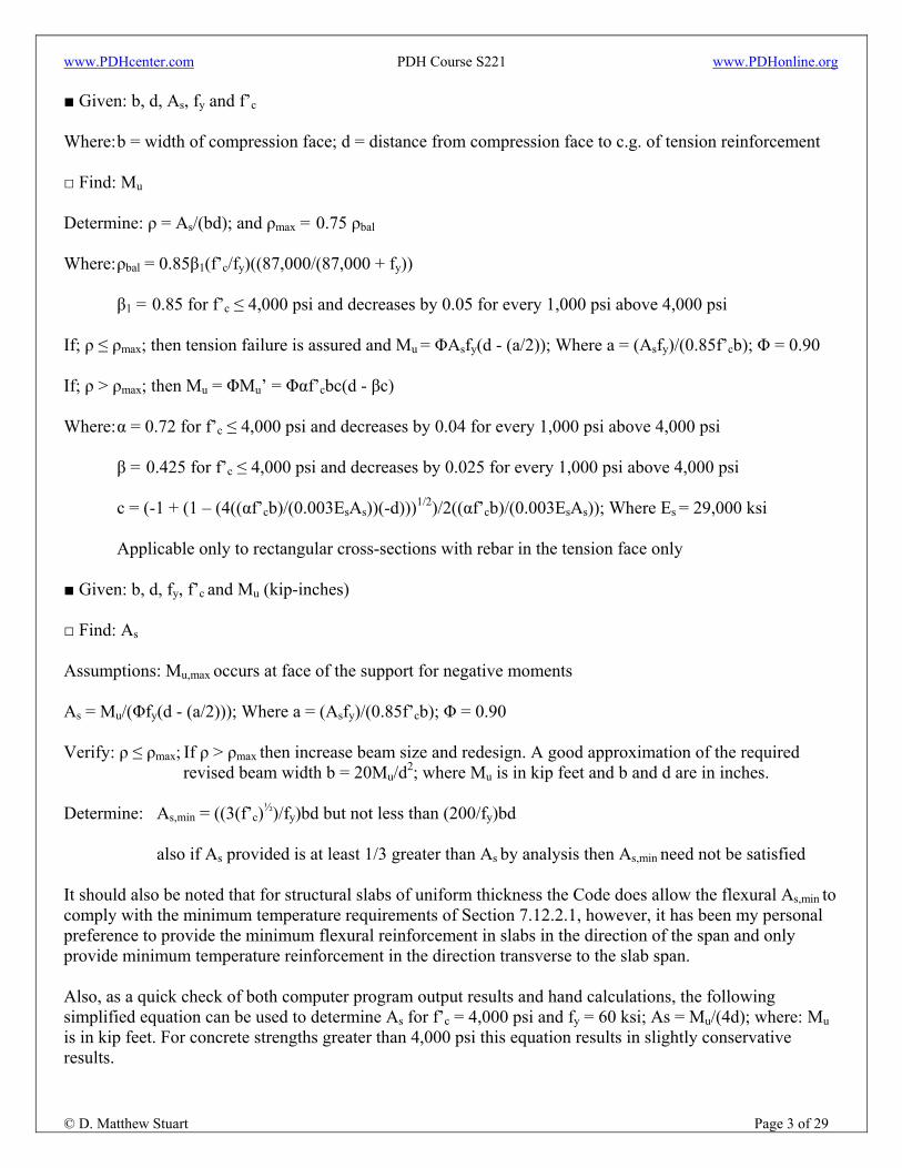
■ Given: b, d, As, fy and f’c
Where: b = width of compression face; d = distance from compression face to c.g. of tension reinforcement □ Find: Mu Determine: ρ = As/(bd); and ρmax = 0.75 ρbal Where: ρbal = 0.85β1(f’c/fy)((87,000/(87,000 + fy))
β1 = 0.85 for f’c ≤ 4,000 psi and decreases by 0.05 for every 1,000 psi above 4,000 psi
If; ρ ≤ ρmax; then tension failure is assured and Mu = ΦAsfy(d - (a/2)); Where a = (Asfy)/(0.85f’cb); Φ = 0.90 If; ρ > ρmax; then Mu = ΦMu’ = Φαf’cbc(d - βc) Where: α = 0.72 for f’c ≤ 4,000 psi and decreases by 0.04 for every 1,000 psi above 4,000 psi β = 0.425 for f’c ≤ 4,000 psi and decreases by 0.025 for every 1,000 psi above 4,000 psi c = (-1 + (1 – (4((αf’cb)/(0.003EsAs))(-d)))1/2)/2((αf’cb)/(0.003EsAs)); Where Es = 29,000 ksi Applicable only to rectangular cross-sections with rebar in the tension face only ■ Given: b, d, fy, f’c and Mu (kip-inches) □ Find: As
Assumptions: Mu,max occurs at face of the support for negative moments As = Mu/(Φfy(d - (a/2))); Where a = (Asfy)/(0.85f’cb); Φ = 0.90 Verify: ρ ≤ ρmax; If ρ > ρmax then increase beam size and redesign. A good approximation of the required
revised beam width b = 20Mu/d2; where Mu is in kip feet and b and d are in inches. Determine: As,min = ((3(f’c)½)/fy)bd but not less than (200/fy)bd
also if As provided is at least 1/3 greater than As by analysis then As,min need not be satisfied
It should also be noted that for structural slabs of uniform thickness the Code does allow the flexural As,min to comply with the minimum temperature requirements of Section 7.12.2.1, however, it has been my personal preference to provide the minimum flexural reinforcement in slabs in the direction of the span and only provide minimum temperature reinforcement in the direction transverse to the slab span. Also, as a quick check of both computer program output results and hand calculations, the following simplified equation can be used to determine As for f’c = 4,000 psi and fy = 60 ksi; As = Mu/(4d); where: Mu is in kip feet. For concrete strengths greater than 4,000 psi this equation results in slightly conservative results.
www.PDHcenter.com PDH Course S221 www.PDHonline.org
© D. Matthew Stuart Page 4 of 29
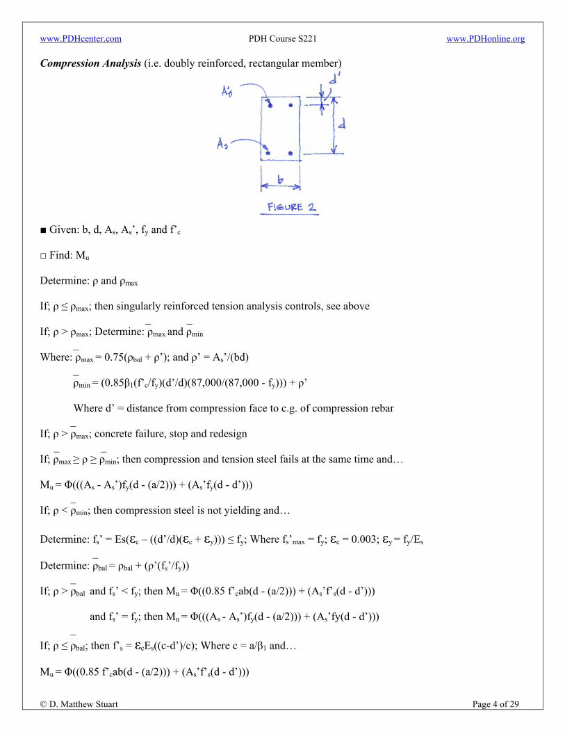
Compression Analysis (i.e. doubly reinforced, rectangular member)
■ Given: b, d, As, As’, fy and f’c □ Find: Mu Determine: ρ and ρmax If; ρ ≤ ρmax; then singularly reinforced tension analysis controls, see above _ _ If; ρ > ρmax; Determine: ρmax and ρmin _ Where: ρmax = 0.75(ρbal + ρ’); and ρ’ = As’/(bd) _ ρmin = (0.85β1(f’c/fy)(d’/d)(87,000/(87,000 - fy))) + ρ’
Where d’ = distance from compression face to c.g. of compression rebar _ If; ρ > ρmax; concrete failure, stop and redesign _ _ If; ρmax ≥ ρ ≥ ρmin; then compression and tension steel fails at the same time and… Mu = Φ(((As - As’)fy(d - (a/2))) + (As’fy(d - d’))) _ If; ρ < ρmin; then compression steel is not yielding and… Determine: fs’ = Es(εc – ((d’/d)(εc + εy))) ≤ fy; Where fs’max = fy; εc = 0.003; εy = fy/Es _ Determine: ρbal = ρbal + (ρ’(fs’/fy)) _ If; ρ > ρbal and fs’ < fy; then Mu = Φ((0.85 f’cab(d - (a/2))) + (As’f’s(d - d’)))
and fs’ = fy; then Mu = Φ(((As - As’)fy(d - (a/2))) + (As’fy(d - d’))) _ If; ρ ≤ ρbal; then f’s = εcEs((c-d’)/c); Where c = a/β1 and… Mu = Φ((0.85 f’cab(d - (a/2))) + (As’f’s(d - d’)))
www.PDHcenter.com PDH Course S221 www.PDHonline.org
© D. Matthew Stuart Page 5 of 29
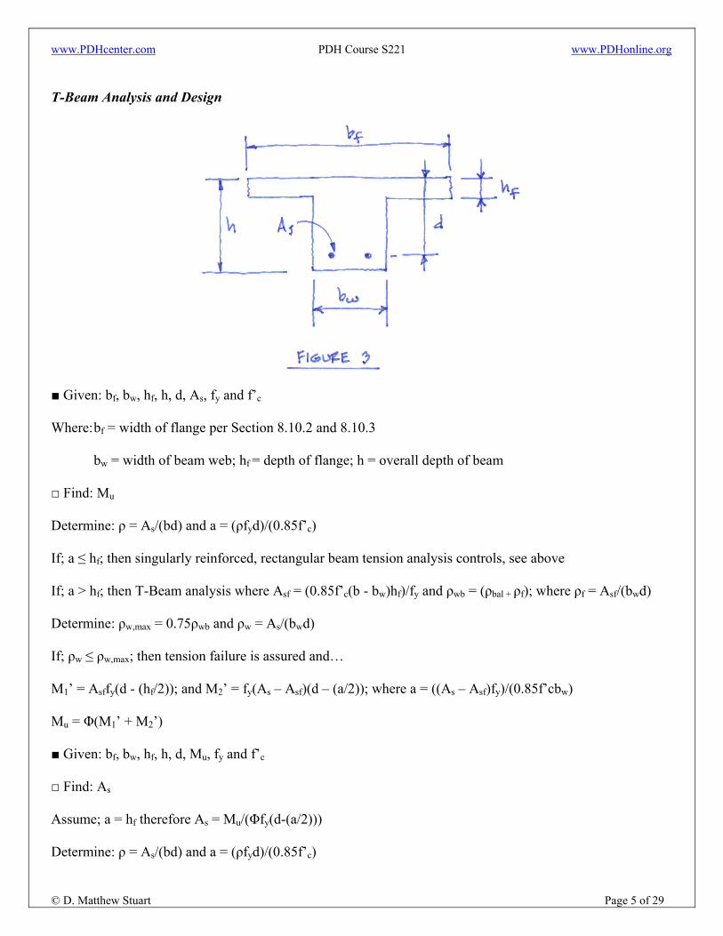
T-Beam Analysis and Design
■ Given: bf, bw, hf, h, d, As, fy and f’c
Where: bf = width of flange per Section 8.10.2 and 8.10.3 bw = width of beam web; hf = depth of flange; h = overall depth of beam □ Find: Mu Determine: ρ = As/(bd) and a = (ρfyd)/(0.85f’c) If; a ≤ hf; then singularly reinforced, rectangular beam tension analysis controls, see above If; a > hf; then T-Beam analysis where Asf = (0.85f’c(b - bw)hf)/fy and ρwb = (ρbal + ρf); where ρf = Asf/(bwd) Determine: ρw,max = 0.75ρwb and ρw = As/(bwd) If; ρw ≤ ρw,max; then tension failure is assured and… M1’ = Asffy(d - (hf/2)); and M2’ = fy(As – Asf)(d – (a/2)); where a = ((As – Asf)fy)/(0.85f’cbw) Mu = Φ(M1’ + M2’) ■ Given: bf, bw, hf, h, d, Mu, fy and f’c □ Find: As
Assume; a = hf therefore As = Mu/(Φfy(d-(a/2))) Determine: ρ = As/(bd) and a = (ρfyd)/(0.85f’c)

www.PDHcenter.com PDH Course S221 www.PDHonline.org
© D. Matthew Stuart Page 6 of 29
If; a ≤ hf; then singularly reinforced, rectangular beam tension design controls, see above If; a > hf; then T-Beam analysis where Asf = (0.85f’c(b-bw)hf)/fy Determine: M1 = ΦAsffy(d - (hf/2)); If M1 ≥ Mu; then no additional steel is needed for flange (i.e. Asf = 0) Determine: M2 = Mu - M1; assume value for a and… Solve for: (As – Asf) = M2/(Φfy(d-(a/2))) and back check assumption for a = ((As – Asf)fy)/(0.85f’cbw) If; a ≠ a assumed then reiterate; If a = a assumed then; As = Asf + (As – Asf) Determine: ρw = As/(bwd) and ρwb = (ρbal + ρf); where ρf = Asf/(bwd) Determine: ρw,max = 0.75ρwb If; ρw ≤ ρw,max then tension failure is assured Shear Design
■ Given: bw, d, Vu, fyt, f’c and Φ = 0.85 □ Find: Av and s (spacing) Assumptions: Vu,max occurs at a distance d from the face of the support unless otherwise stipulated by
Section R11.1.3.1 Determine: Vc = 2(f’c)½bwd
(it should be noted that Section 11.3 includes other checks for Vc under special conditions) If; ΦVc ≥ Vu; then no shear reinforcement is required, however, if 0.5ΦVc < Vu then Av,min is required
unless member is slab, joist (as defined by Section 8.11) or beam with h ≤ 10 inches, 2.5hf or 0.5bw.
Determine: Av,min = (0.75(f’c)½)((bws)/fyt) but not less than (50bws)/fyt; where smax = d/2
www.PDHcenter.com PDH Course S221 www.PDHonline.org
© D. Matthew Stuart Page 7 of 29
If; ΦVc < Vu; then shear reinforcement is required and Vu ≤ Φ(Vc + Vs) Determine: Av/s = (Vu – (ΦVc))/(Φfytd); from Vs = (Avfytd)/s where Vs,max = 8(f’c)½bwd Assume spacing and determine Av or assume an Av and determine spacing Note that Av = 2 x Ab; or Ab = Av/2; where Ab = the cross-sectional area of one vertical leg of a stirrup Shear and Torsion Design
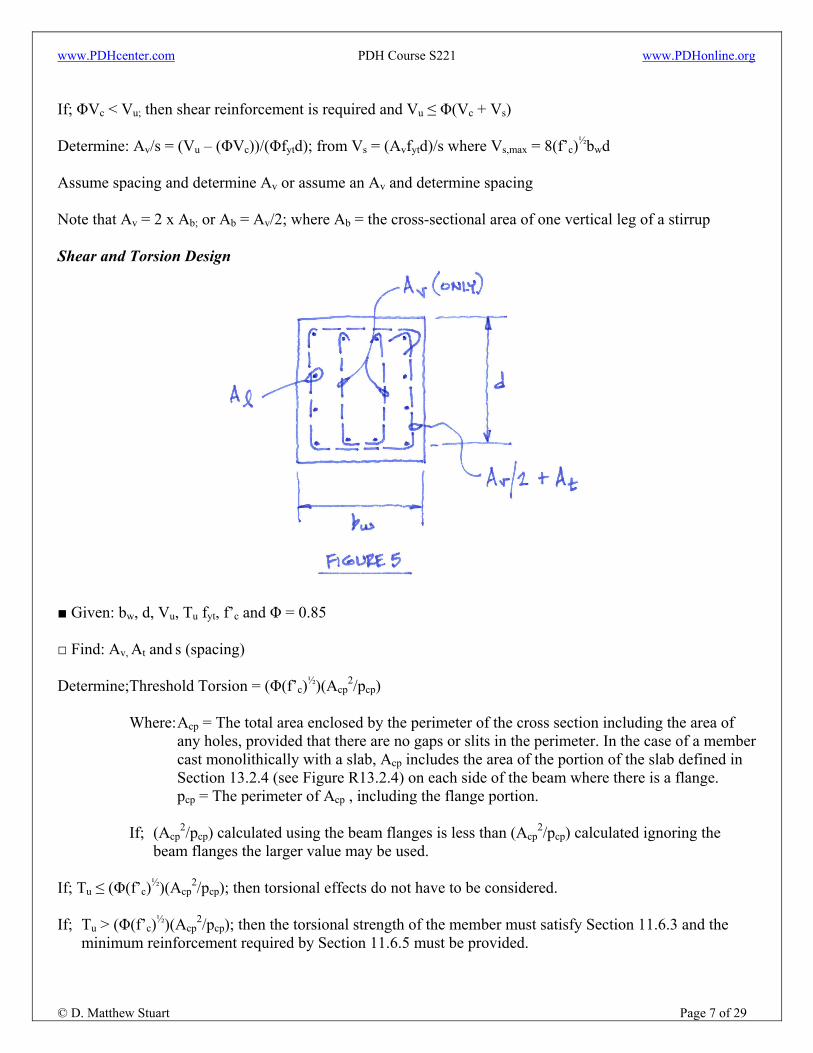
■ Given: bw, d, Vu, Tu fyt, f’c and Φ = 0.85 □ Find: Av, At and s (spacing) Determine;Threshold Torsion = (Φ(f’c)½)(Acp
2/pcp)
Where: Acp = The total area enclosed by the perimeter of the cross section including the area of any holes, provided that there are no gaps or slits in the perimeter. In the case of a member cast monolithically with a slab, Acp includes the area of the portion of the slab defined in Section 13.2.4 (see Figure R13.2.4) on each side of the beam where there is a flange.
pcp = The perimeter of Acp , including the flange portion. If; (Acp
2/pcp) calculated using the beam flanges is less than (Acp2/pcp) calculated ignoring the
beam flanges the larger value may be used. If; Tu ≤ (Φ(f’c)½)(Acp
2/pcp); then torsional effects do not have to be considered. If; Tu > (Φ(f’c)½)(Acp
2/pcp); then the torsional strength of the member must satisfy Section 11.6.3 and the minimum reinforcement required by Section 11.6.5 must be provided.

www.PDHcenter.com PDH Course S221 www.PDHonline.org
© D. Matthew Stuart Page 8 of 29
It should be noted that if the torsional moment in a member can be redistributed (see Figure 6) then the maximum design Tu can be reduced to 4(Φ(f’c)½)(Acp
2/pcp). However, if the applied torsional moment cannot be redistributed (see Figure 7) then the maximum Tu cannot be reduced.
FIGURE 6
FIGURE 7
Per Section 11.6.3; ((Vu/(bwd))2 + ((Tuph)/(1.7A2
oh))2)½ ≤ Φ((Vc/(bwd)) + 8(f’c)½ ) Where: Aoh = The area enclosed by the centerline of the outermost closed stirrup (see Figure 8) ph = The perimeter of the outermost closed stirrup used to define Aoh
FIGURE 8
If; ((Vu/(bwd))2 + ((Tuph)/(1.7A2
oh))2)½ > Φ((Vc/(bwd)) + 8(f’c)½ ); then increase beam size Per Section 11.6.5.2; The minimum area of closed stirrups shall be (Av + 2At) = 0.75(f’c)½((bws)/fyt) ≥ (50bws)/fyt
Where; Av = the area of two legs of the stirrup; and At = the area of only one leg smax = ph/8 or 12 inches

www.PDHcenter.com PDH Course S221 www.PDHonline.org
© D. Matthew Stuart Page 9 of 29
Assume spacing and determine (Av + 2At) or assume (Av + 2At) and determine spacing Confirm; ΦTn ≥ Tu; Where Tn = ((2AoAtfyt)/s)cotθ; Where Ao = 0.85Aoh; and θ = 45º If; ΦTn < Tu; then increase (Av + 2At) or reduce spacing and reiterate It should be noted that only the legs of a stirrup that are adjacent to the sides of the beam are effective in resisting torsion, therefore any internal stirrup legs can only be used towards satisfying the requirements of Av. Determine;Aℓ = (At/s)ph(fyt/fy)cot2θ; Where Aℓ = longitudinal reinforcement
Which is additive to any longitudinal reinforcement required for flexural bending.
Confirm; Aℓ ≥ Aℓ,min = ((5(f’c)½Acp)/fy) – ((At/s)ph(fyt/fy)); Where; At/s ≥ 25bw/fyt Longitudinal reinforcement required for torsion shall be distributed around the perimeter of within the closed stirrups at a maximum spacing of 12 inches on center. In addition, there shall be at least one longitudinal bar located in each corner of the closed stirrups. Longitudinal bars shall have a diameter of at least 0.042 times the stirrup spacing, but not less than 3/8 inch. Torsional reinforcement shall be provided for a distance of at least (bt +d) beyond the point required by analysis, where bt = the width of that part of the cross section containing the closed stirrups that resist any torsion. Methods of Gravity Load Analysis
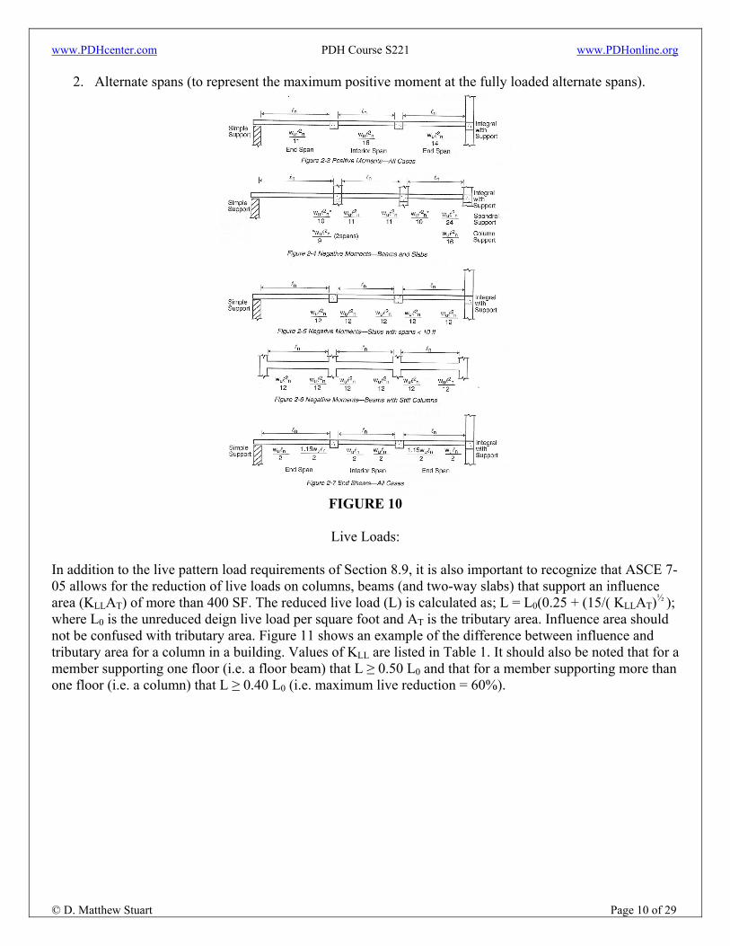
ACI Moment and Shear Coefficients: Cast-in-place concrete structures are somewhat different from steel buildings in that the monolithic nature of the material results in continuous beam and slab spanning capabilities. As a result there are many computer programs and proprietary software packages available that can calculate the shear and moments diagrams for continuous concrete beams and slabs for a wide range of applied gravity loads and span conditions. However, ACI Section 8.3 does provide an alternate method of determining maximum shears and moments using coefficients (see Figure 10). The use of the coefficients is limited however to the following provisions:
1. There must be at least two or more spans. 2. Spans must be approximately equal with the larger of two adjacent spans not greater than the shorter
span by 20%. 3. The loads must be uniformly distributed. 4. The unfactored live load cannot exceed three times the unfactored dead load. 5. Members must be prismatic (i.e. not variable inertia)
In addition, the coefficients do not account for pattern or skip loading as required by Section 8.9. Section 8.9.2 requires than in addition to the full factored dead and live load being applied to all spans that the full factored live load (in the presence of the full factored dead on all spans) shall also be applied on:
1. Two adjacent spans only (to represent the maximum negative moment possible at any given support), and…
www.PDHcenter.com PDH Course S221 www.PDHonline.org
© D. Matthew Stuart Page 10 of 29
2. Alternate spans (to represent the maximum positive moment at the fully loaded alternate spans).
FIGURE 10
Live Loads:
In addition to the live pattern load requirements of Section 8.9, it is also important to recognize that ASCE 7-05 allows for the reduction of live loads on columns, beams (and two-way slabs) that support an influence area (KLLAT) of more than 400 SF. The reduced live load (L) is calculated as; L = L0(0.25 + (15/( KLLAT)½ ); where L0 is the unreduced deign live load per square foot and AT is the tributary area. Influence area should not be confused with tributary area. Figure 11 shows an example of the difference between influence and tributary area for a column in a building. Values of KLL are listed in Table 1. It should also be noted that for a member supporting one floor (i.e. a floor beam) that L ≥ 0.50 L0 and that for a member supporting more than one floor (i.e. a column) that L ≥ 0.40 L0 (i.e. maximum live reduction = 60%).

www.PDHcenter.com PDH Course S221 www.PDHonline.org
© D. Matthew Stuart Page 11 of 29
FIGURE 11
TABLE 1
Control of Deflections:
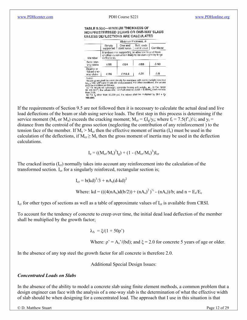
Once the shear and moment design envelopes have been established and the members properly designed for shear, torsion and flexure, it is also necessary to check the serviceability of the section (i.e. deflection). This is particularly critical for concrete because of the impact of creep which causes long-term growth of the initial dead (or any permanently sustained) load deflection. A further discussion of the impact of creep on the deflection of concrete members will be discussed later. Deflections of one-way beams and slabs (that do not support or are not attached to partitions or other types of construction that can be damaged by large deflections) do not need to be computed, however, if the overall member depth or thickness meets the minimum specified in ACI Table 9.5(a), see below. ℓ in Table 9.5(a) is the clear span of the member.
www.PDHcenter.com PDH Course S221 www.PDHonline.org
© D. Matthew Stuart Page 12 of 29
If the requirements of Section 9.5 are not followed then it is necessary to calculate the actual dead and live load deflections of the beam or slab using service loads. The first step in this process is determining if the service moment (Ms or Ma) exceeds the cracking moment; Mcr = frIg/yt; where fr = 7.5(f’c)½; and yt = distance from the centroid of the gross section (neglecting the contribution of any reinforcement ) to the tension face of the member. If Ms > Mcr then the effective moment of inertia (Ie) must be used in the calculation of the deflections, if Mcr ≥ Ms then the gross moment of inertia may be used in the deflection calculations.
Ie = ((Mcr/Ms)3Ig) + (1 - (Mcr/Ms)3)Icr The cracked inertia (Icr) normally takes into account any reinforcement into the calculation of the transformed section. Icr for a singularly reinforced, rectangular section is;
Icr = b(kd)3/3 + nAs(d-kd)2
Where: kd = (((4(nAs)d(b/2)) + (nAs)2 )½ - (nAs))/b; and n = Es/Ec Icr for other types of sections as well as a table of approximate values of Icr is available from CRSI. To account for the tendency of concrete to creep over time, the initial dead load deflection of the member shall be multiplied by the growth factor;
λΔ = ξ/(1 + 50ρ’)
Where: ρ’ = As’/(bd); and ξ = 2.0 for concrete 5 years of age or older. In the absence of any top steel the growth factor for all concrete is therefore 2.0.
Additional Special Design Issues: Concentrated Loads on Slabs In the absence of the ability to model a concrete slab using finite element methods, a common problem that a design engineer can face with the analysis of a one-way slab is the determination of what the effective width of slab should be when designing for a concentrated load. The approach that I use in this situation is that

www.PDHcenter.com PDH Course S221 www.PDHonline.org
© D. Matthew Stuart Page 13 of 29
which is recommended by Bulletin 80 of the OSU Engineering Experiment Station. This approach is rational as long as the width of distribution calculated does not exceed the clear span of the slab. Beams with Web Openings Just as is the case with deep steel beams, it is often necessary to provide openings through the web of a concrete beam in order to allow for the penetration of mechanical ducts or piping. An example of a typical reinforcing arrangement in a concrete beam with web openings is shown in Figure 12a and 12b. The analysis of an opening in a concrete beam is similar to that of the analysis of a web opening in a steel beam in that the shear and moment that occur at the opening are portioned to be resisted by the remaining sections of the beam above and below the opening based on the relative shear resistance (bd) and flexural stiffness (i.e. moment of inertia) of the respective elements. In addition, the Vierendeel effects of the opening on the effected cross section must also be accounted for. For a further discussion of this topic see the ACI Structural Journal, January 1967 and July-August 1996.
FIGURE 12a FIGURE 12b Design Documentation The final step in the process of designing a concrete beam or slab is documenting the results of the design so that the contractor (including the reinforcing and formwork subcontractors) can have a clear understanding of what is to be built in the field. Some of the required information, as with other structural systems, is communicated through the framing plans where the location, extent and direction of span of the beams and or slabs are shown. The most critical aspect of this communication process however is the development of the beam and or slab schedule. A beam/slab schedule provides the contractor with the size of the member (or slab thickness), type, number and extent of the flexural and shear reinforcement, and additional notes that pertain to the construction of each individual member. Each beam (and slab) in the schedule is also typically referenced to a diagram which shows an elevation of the beam (or slab) and the orientation of the reinforcement. An example of a beam schedule template, related beam diagrams and stirrup details are shown in Figures 13a through 13h. The development of a schedule is really more of an art form than a technical regurgitation of the design. This is because the schedule reflects the designer’s expertise, experience and understanding of all of the construction efficiencies and reinforcing bar placement constraints discussed in the following portions of the lecture (see the section below on Reinforcement).

www.PDHcenter.com PDH Course S221 www.PDHonline.org
© D. Matthew Stuart Page 14 of 29
FIGURE 13a
FIGURE 13b FIGURE 13c
FIGURE 13d FIGURE 13e
FIGURE 13f FIGURE 13g
FIGURE 13h

www.PDHcenter.com PDH Course S221 www.PDHonline.org
© D. Matthew Stuart Page 15 of 29
Selection of Concrete Framing Systems Concrete, reinforcement, and formwork are the three primary components of the costs associated with cast-in-place concrete floor and roof construction. All three of these factors must be taken into account during the design process, especially during the initial planning stages. Of these three cost factors, formwork comprises about 50% to 60% of the total cost and therefore has the greatest influence on the overall cost of the framing system. The cost of the concrete, including placing and finishing, typically accounts for only about 25% to 30% percent of the overall cost. Reinforcing steel has the lowest influence on the overall cost.
Formwork and Concrete Placement: To achieve overall economy, designers should satisfy the following three basic principles of formwork efficiency:
1. Specify readily available standard form sizes. Rarely will custom forms be economical unless they are required in a quantity that allows for mass production.
2. Repeat sizes and shapes of the concrete members wherever possible. Repetition allows reuse of
forms from bay to bay and from floor to floor.
3. Strive for simple formwork. In cast-in-place concrete construction, economy is rarely achieved by reducing quantities of materials. For example, changing the depth of a beam as the loading and span varies results in only a moderate savings in materials and substantial additional costs in formwork, resulting in a more expensive structure. The simplest and most cost-effective solution involves providing a constant beam depth (and width if possible) and varying the reinforcement as required for the span and loads. Simple formwork can also make construction time shorter, resulting in a building that can be occupied sooner.
In cast-in-place, multi-story concrete buildings, a “typical floor” construction cycle of 5 to 7 days per floor is easily achievable and 2 and 3 days cycling is not uncommon in some areas. Often night and early morning concrete placing operations are scheduled to take advantage of more efficient concrete delivery (i.e., less traffic on the roads) and to mitigate curing and finishing concerns due to higher daytime temperatures in order to help facilitate rapid turn around. In addition high strength concrete or high-early strength (using Type III cement) concrete is used to accelerate concrete strength to shorten stripping and formwork turn around time. Formwork systems in use today for rapid and normal cycle construction of horizontal framing systems can be grouped into five general categories:
1. Sticks: This type of formwork (see Figure 14) involves basically loose wood framing members. It is a very flexible system but is also very material and labor intensive which results in additional costs and slower strip and reforming cycles.
FIGURE 14

www.PDHcenter.com PDH Course S221 www.PDHonline.org
© D. Matthew Stuart Page 16 of 29
2. Table or Gang: This type of formwork (see Figure 15) includes panelized plywood deck supported by wood or aluminum framing (or other similar materials) which in turn is supported on pre-attached shoring posts. This type of formwork is also fairly flexible but is more productive, efficient and safer than stick systems.
FIGURE 15
3. Flying Truss or Form: This system (see Figure 16) involves steel or aluminum trusses or beams that
support plywood deck supported by wood or aluminum sub-framing. The preassembled form is flown in and out of the structure between previously cast permanent vertical support elements (i.e. columns) and is supported either on adjustable vertical posts or temporary brackets mounted to the permanent columns. This type of system is very productive but does have some disadvantages such as the air space that is required in order to fly the forms in and out of the building.
FIGURE 16
4. HV (High Velocity) - Knock Down: This system (see Figure 17) involves short interlocking members
supported from high capacity shoring posts. This system allows for the quick recover of the deck framing materials.
FIGURE 17

www.PDHcenter.com PDH Course S221 www.PDHonline.org
© D. Matthew Stuart Page 17 of 29
5. Steel “Beams”. This system (see Figure 18) involves the use of prefabricated standard steel forms, supported on shoring stands, which in turn support a panelized slab form that typically spans from steel beam to steel beam.
FIGURE 18
In order to form joists or other similar beam sections above the soffit of the main form deck, prefabricated domes, pans and forms are used. There are a variety of these types of forms available which include; fiberglass domes (see Figure 19) that are used exclusively in two-way ‘waffle” slabs, flange forms (see Figure 20) and wide or long forms (see Figure 21).
FIGURE 19

www.PDHcenter.com PDH Course S221 www.PDHonline.org
© D. Matthew Stuart Page 18 of 29
FIGURE 20
FIGURE 21
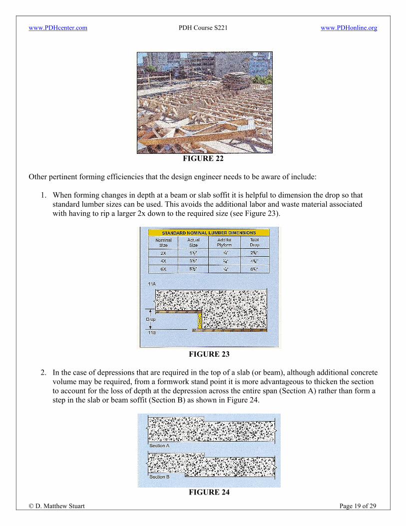
Similar voids between joists and beams can also be formed with trussed wood formwork (see Figure 22).
www.PDHcenter.com PDH Course S221 www.PDHonline.org
© D. Matthew Stuart Page 19 of 29
FIGURE 22
Other pertinent forming efficiencies that the design engineer needs to be aware of include:
1. When forming changes in depth at a beam or slab soffit it is helpful to dimension the drop so that standard lumber sizes can be used. This avoids the additional labor and waste material associated with having to rip a larger 2x down to the required size (see Figure 23).
FIGURE 23
2. In the case of depressions that are required in the top of a slab (or beam), although additional concrete
volume may be required, from a formwork stand point it is more advantageous to thicken the section to account for the loss of depth at the depression across the entire span (Section A) rather than form a step in the slab or beam soffit (Section B) as shown in Figure 24.
FIGURE 24

www.PDHcenter.com PDH Course S221 www.PDHonline.org
© D. Matthew Stuart Page 20 of 29
3. At interior beam/column intersections it is preferable that the depth of the girder matches the depth of
the intersecting perpendicular or transverse joists or beams. When this is not possible and the girder must be deeper than the transverse framing system, then it is preferable to make the width of the deeper section of the girder the same width as the column in order to avoid having to notch the girder bottom form to fit around the top of the already cast column. However, if a wider deeper girder is unavoidable then the offset dimension (as shown in Figure 25) should comply with the standard lumber dimensions shown in Figure 23 above.
FIGURE 25
4. Similar to Item #3 above, at an exterior column and edge spandrel intersection, the depth of the
spandrel should ideally be the same depth (Section A, Figure 26) as the intersecting transverse or parallel joists or beams. If this is not possible it is preferable, from a formwork efficiency standpoint, to make the deeper portion of the spandrel the same width as the column for reasons similar to that described above. If this is not possible due to depth restrictions of the spandrel soffit, then it is less costly, again from a formwork standpoint, to upturn the beam (Section B, Figure 26) in order to avoid the need to deepen the beam soffit, particularly if deepening the beam soffit results in the spandrel width not matching the width of the column (Section C, Figure 26).
FIGURE 26
For a multistory building the sequence of forming, shoring and subsequent re-support (i.e. shore replacement) of floors that have already been cast and are used to support the main formwork and shores is critical to the success of the construction cycle turn around of a concrete framed building. ACI’s Guide to Formwork for Concrete discusses the two most common shore replacement methods which are backshoring and reshoring. Backshoring allows early age stripping since only small slab areas are unsupported during the removal and replacement process. Backshoring requires a large amount of reshore material. Reshoring

www.PDHcenter.com PDH Course S221 www.PDHonline.org
© D. Matthew Stuart Page 21 of 29
allows for quick removal of shores and uses less material than backshoring since fewer levels need to be reshored. See Table 2 for a comparison of the backshoring and reshoring methods. In the reshoring method, all the shores under the most recently cast floor are removed so that the load in the framing below reduces to only it’s self-weight plus the weight of the reshores. The most recently cast framed level in turn is only subjected to its own self weight. Reshores are then installed under this same most recently cast level and formwork for the next floor is built on top of this same level. When the next slab is cast, its weight, plus that of the formwork and the concreting operation live load will be shared by the shored in-place, or reshored levels below. In the reshore approach it is imperative that the reshores are installed in such a manner that they are not preloaded. It is also imperative in this approach to consider the strength development of the most recently cast slab at the point in time when form stripping and reshoring is desired. The key element of a reshoring analysis is the portioning of the construction loads throughout the system of framed levels interconnected by the shores and reshores.
TABLE 2
In order to evaluate the structural affects of the forming system being employed, two questions need to be answered:
1. What portion of the temporary loads goes to each of the floors interconnected by the formwork system?
2. What is the capacity of each of the interconnected floors?
In addition, it should be noted that four conditions influence the distribution of the temporary shoring loads:
1. The effects of cure time on f’c and Ec. 2. The relative stiffness of the interconnected floors.
3. The number of interconnected floors.
4. The particular method of reshoring, pre-shoring or backshoring employed.
It is generally accepted that the following assumptions can be used to determine the shoring load distribution:
1. Flexural stress is relative to deformation. In other words, a slab that is not allowed to deflect will not carry any load.
2. Stiffness is related to concrete strength development as well as cross section.

www.PDHcenter.com PDH Course S221 www.PDHonline.org
© D. Matthew Stuart Page 22 of 29
3. In comparison to the floors, the shores, reshores or backshores are infinitely rigid. These vertical
elements therefore are assumed to not deform and only serve to interconnect the supporting floors. The following conclusions concerning the determination of the formwork load distribution are based on the above assumptions:
1. Floors interconnected by shores, reshores or backshores will deflect equally under application of the temporary construction loads.
2. Interconnected floors will share the construction load in proportion to their relative flexural stiffness.
3. A compacted subgrade or a slab on grade is assumed to be an unyielding support, therefore floors
shored or backshored to grade will not therefore not carry any of the construction load.
Floor Framing Systems: Bay spacings of thirty feet or less can be framed economically with conventionally reinforced joists, beams, and girders using structural depths ranging from 18 to 22 inches. In addition, the use of 24 inch deep pan forms allows for economical joist spans of 35 to 40 feet, however to maintain constant joist, beam and girder depths, post-tensioning is usually required. One-way beam, joist and slab systems that are commonly used in framed concrete structures include; Pan Joists, Wide-Module or Skip Joists, One-Way Beam and Slabs, and Banded Beams. One-Way Joists A standard one-way joist floor system consists of evenly spaced concrete joists (i.e. ribs) spanning in one direction, a reinforced concrete slab cast integrally with and spanning transverse to the joists, and beams that span between the columns perpendicular to the joists (see Figure 27). Typical pan forms that are used to construct this system are 30 inches wide and range in depth from 8 to 24 inches. The varying depths of pans and resulting concrete cross sections provide flexibility to satisfy a wide range of span and loading conditions. The main advantage of this system is the reduced dead load made possible by the pan.
FIGURE 27
www.PDHcenter.com PDH Course S221 www.PDHonline.org
© D. Matthew Stuart Page 23 of 29
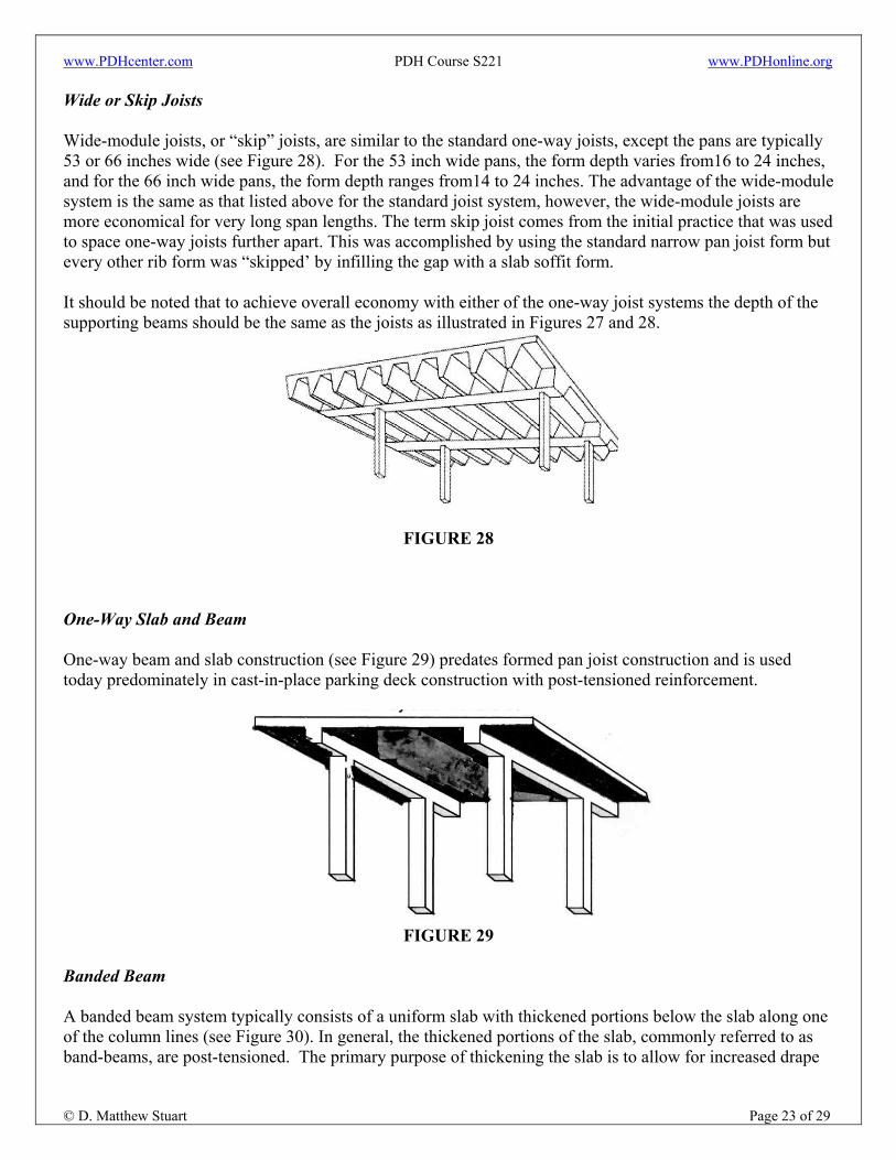
Wide or Skip Joists Wide-module joists, or “skip” joists, are similar to the standard one-way joists, except the pans are typically 53 or 66 inches wide (see Figure 28). For the 53 inch wide pans, the form depth varies from16 to 24 inches, and for the 66 inch wide pans, the form depth ranges from14 to 24 inches. The advantage of the wide-module system is the same as that listed above for the standard joist system, however, the wide-module joists are more economical for very long span lengths. The term skip joist comes from the initial practice that was used to space one-way joists further apart. This was accomplished by using the standard narrow pan joist form but every other rib form was “skipped’ by infilling the gap with a slab soffit form. It should be noted that to achieve overall economy with either of the one-way joist systems the depth of the supporting beams should be the same as the joists as illustrated in Figures 27 and 28.
FIGURE 28
One-Way Slab and Beam One-way beam and slab construction (see Figure 29) predates formed pan joist construction and is used today predominately in cast-in-place parking deck construction with post-tensioned reinforcement.
FIGURE 29
Banded Beam A banded beam system typically consists of a uniform slab with thickened portions below the slab along one of the column lines (see Figure 30). In general, the thickened portions of the slab, commonly referred to as band-beams, are post-tensioned. The primary purpose of thickening the slab is to allow for increased drape

www.PDHcenter.com PDH Course S221 www.PDHonline.org
© D. Matthew Stuart Page 24 of 29
of the tendons that are “banded” in the beam, hence the reason the system is referred to as banded-beam. Increasing the tendon drape allows for more efficient use of the post-tensioning strands. The overall thickness of a band-beam is typically 12 to 18 inches. The width of a band-beam can vary from 4 to 10 feet, however, it is common to treat the maximum width of the band-beam as if it were a drop panel in a two-way flat plate and limit one half the width of the beam to 1/6 of the transverse center to center column spacing. Depending on the spans and loads, the slab is usually 7 to 9 inches thick. One of the main advantages of this system is that long-unobstructed spans can be achieved with a minimum structural floor depth. This results in lower floor-to-floor heights and subsequent significant cost savings in the overall building construction cost.
FIGURE 30
Lateral Load Resisting Systems:
Wind and earthquake lateral forces are for the most part resisted by a concrete building by either rigid moment frames or shearwalls. Vertical bracing is very seldom if ever used in a cast-in-placed reinforced concrete structure. Rigid moment frames consist of horizontal members (typically beams) and vertical members (columns) which are connected at the monolithic intersections of these two member types. The strength and stiffness of the moment frame is proportional to the column and beam size, and inversely proportional to the floor-to-floor height and column spacing. During the initial modeling of a concrete moment frame it is common to assume that the effective inertia of the beams is one half of the gross inertia. During final modeling of the frame a more refined analysis of the effective inertia of all of the members is performed. Shearwalls are designed as thin slender beam/column elements that essentially cantilever vertically to resist the imposed lateral forces. Shearwalls are typically located in core areas of a building (around stair and elevator shafts), therefore the structural configuration of the walls is usually limited/dictated by the architectural constraints of the space. Both moment frames and shearwalls provide economical design and construction solutions for concrete buildings. However, in general, shearwalls are more economical than moment frames for buildings over 8 stories. High seismic loads require special detailing of reinforcing in order to achieve code mandated ductile behavior of the structure. Therefore, where seismic loads are a consideration a significant increase in design, detailing, and total reinforcing steel cost should be anticipated.
www.PDHcenter.com PDH Course S221 www.PDHonline.org
© D. Matthew Stuart Page 25 of 29
Fire Resistance:
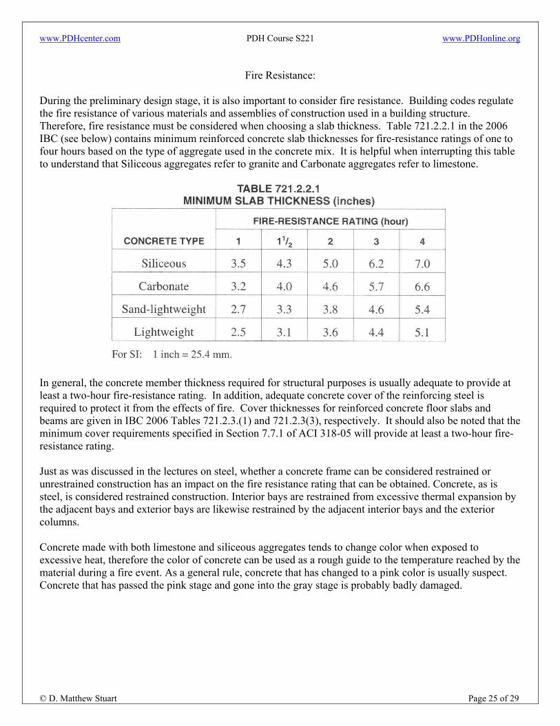
During the preliminary design stage, it is also important to consider fire resistance. Building codes regulate the fire resistance of various materials and assemblies of construction used in a building structure. Therefore, fire resistance must be considered when choosing a slab thickness. Table 721.2.2.1 in the 2006 IBC (see below) contains minimum reinforced concrete slab thicknesses for fire-resistance ratings of one to four hours based on the type of aggregate used in the concrete mix. It is helpful when interrupting this table to understand that Siliceous aggregates refer to granite and Carbonate aggregates refer to limestone.
In general, the concrete member thickness required for structural purposes is usually adequate to provide at least a two-hour fire-resistance rating. In addition, adequate concrete cover of the reinforcing steel is required to protect it from the effects of fire. Cover thicknesses for reinforced concrete floor slabs and beams are given in IBC 2006 Tables 721.2.3.(1) and 721.2.3(3), respectively. It should also be noted that the minimum cover requirements specified in Section 7.7.1 of ACI 318-05 will provide at least a two-hour fire-resistance rating. Just as was discussed in the lectures on steel, whether a concrete frame can be considered restrained or unrestrained construction has an impact on the fire resistance rating that can be obtained. Concrete, as is steel, is considered restrained construction. Interior bays are restrained from excessive thermal expansion by the adjacent bays and exterior bays are likewise restrained by the adjacent interior bays and the exterior columns. Concrete made with both limestone and siliceous aggregates tends to change color when exposed to excessive heat, therefore the color of concrete can be used as a rough guide to the temperature reached by the material during a fire event. As a general rule, concrete that has changed to a pink color is usually suspect. Concrete that has passed the pink stage and gone into the gray stage is probably badly damaged.
www.PDHcenter.com PDH Course S221 www.PDHonline.org
© D. Matthew Stuart Page 26 of 29
Reinforcement: Although the topic of reinforcement is being discussed last in this lecture, it should still be recognized that the incorporation of the spacing and placement limitations of rebar must be accounted for during the initial design phase of any concrete element or structure. Although ASTM A615 reinforcing steel is available in 3 grades (Grade 40, Grade 60 and Grade 75) Grade 60 bars continue to be the most common grade of reinforcing bars used in construction. Many steel manufacturers, however, produce Grade 75 reinforcing bars. The use of Grade 75 bars is an economical solution to help reduce congestion in columns and beams. However, the availability of Grade 75 reinforcing should be verified prior to the initial design phase. Grade 60 reinforcing steel is also available in low-alloy steel, ASTM A706. The ASTM A706 specification limits the chemical composition and carbon equivalent of the material to enhance the weldability of the reinforcement. The following rules of thumb should be considered when scheduling beam/slab, column and wall reinforcement: Beams:
1. Use fewer, larger bars rather than more, smaller bars, while still meeting the crack control requirements of the code. Installation is faster and more economical with fewer bars.
2. Always provide repetition in bar sizes and patterns in order to facilitate increased speed of fabrication
and field installation. Reducing the size of a bar between adjacent beams, for example, will create more problems than any savings from the reduced amount of material.
3. Where possible, space longitudinal bars at least six inches apart. This minimum spacing allows
ironworkers enough room to install and tie reinforcing bars. Closely spaced bars create congestion and tend to slow rebar installation.
4. Minimum spacing values often control when sizing beam stirrups, therefore the smallest practical
size of stirrup (generally #3 for joists and #4 for beams) placed at varied spacings will usually result in the most economical solution. Where pan systems are used to form wide (or narrow) joists, it is common to use welded wire fabric or fabricated, articulated “zigzag” patterned rebar for shear reinforcing in lieu of conventional, “open” two legged shear stirrups. Single leg “J” stirrups are also commonly used in joists and narrow beams.
5. In one-way construction, where the top bars of each one-way orthogonal system intersect and
overlap, in order to account for the reduction in depth from the bottom compression face of the beam to the center of gravity of the tension reinforcement, it is necessary to reduce the “d” for at least one of the framing elements assumed in the design of the same member.
Columns:
1. Use fewer, larger bars rather than more, smaller bars. Using fewer vertical bars can reduce the number of ties (which are labor intensive to fabricate and install) which subsequently reduces fabrication and placement labor costs associated with the construction of column reinforcing cages.

www.PDHcenter.com PDH Course S221 www.PDHonline.org
© D. Matthew Stuart Page 27 of 29
2. Column sizes should be proportioned to allow for maximum reinforcement to gross area of concrete ratios of 1 to 2% to avoid rebar congestion. In addition, it should be noted that for architecturally oversized column cross sections the Code allows a minimum steel to gross area of concrete ratio of only ½%.
3. Where sufficient spacing between adjacent interior vertical column bars is present, consider using
“tangential” (straight bar) lap splices in lieu of the typical, offset bend (see Figure 31) lap splice.
FIGURE 31
4. The transition of column vertical bars between adjacent floor levels should be taken into
consideration during the design process in order to help simplify the detailing and installation of the column reinforcement. Maintaining the same number of column vertical bars for the entire height of the building, but varying bar size, is common. Where this is not practical, transitioning from multiple numbers of bars, for example, 16 bars to 8 bars is the most economical option.
5. A good way to transition from a round column to a square column (or vice versa) is to use the same
shaped cage throughout the entire building height. For instance, use a square cage in the lower lifts of a round column that will transition to a smaller-sized square column on an upper level.
6. Using higher strength concrete in columns than the supported horizontal framed levels makes it
possible to use smaller column sizes. However, in order to adhere to the ACI Code maximum reinforcement ratio of 8% of the gross column area at the rebar splice zones, smaller column sizes will tend to require mechanical couplers in lieu of lap splices. Mechanical couplers can increase the cost of material and labor for column reinforcement. Increasing the specified strength of the column concrete will not add significant costs to the concrete price, therefore in general this approach does not add any appreciable labor or material costs to the project. However, it should be noted that if the column concrete strength is greater than 1.4 times the concrete strength of a supported horizontal framed level, it is necessary to cast a portion of the framed level around the column using the same higher strength concrete in order to satisfy the Code. The extent of the higher strength concrete that must be used in the framed level is specified in the ACI Code.
7. Where mechanical couplers are required, compression couplers (which are less expensive than
tension couplers) should be specified if allowed by the column design. Walls:
1. The keys to economical concrete wall construction include maintaining a constant wall thickness, providing sufficient wall thickness to permit proper placement of the vertical and horizontal bars and
www.PDHcenter.com PDH Course S221 www.PDHonline.org
© D. Matthew Stuart Page 28 of 29
splices as required to allow for proper vibrating and consolidation, and specifying fewer different bar sizes and spacings.
2. More often than not, only minimum reinforcing is required in concrete shearwalls. Therefore the
same reinforcing bar size and spacing should be used in as many areas as possible over the entire wall height. One of the most expensive items associated with wall construction are pilasters. If possible, column cages at the ends or corners of a wall should be designed and detailed to fit within the boundary of the wall in order to avoid pilasters.
When selecting bar sizes, it is important to consider the minimum and maximum number of reinforcing bars that are permitted in a cross-section. The limits are a function of the following ACI requirements for spacing, cover and cracking:
• Sections 7.6 and 3.3.2 (spacing limits) • Section 7.7 (concrete cover limits)
• Section 10.6 (flexural cracking limits)
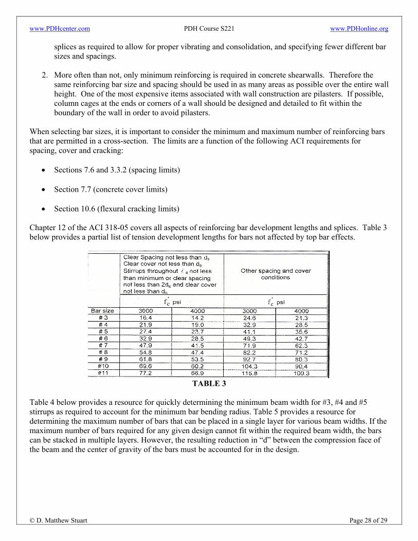
Chapter 12 of the ACI 318-05 covers all aspects of reinforcing bar development lengths and splices. Table 3 below provides a partial list of tension development lengths for bars not affected by top bar effects.
TABLE 3
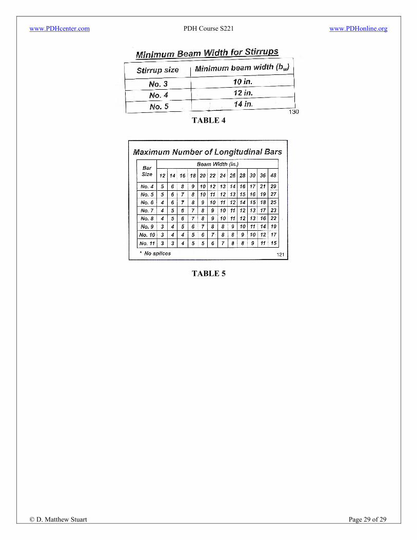
Table 4 below provides a resource for quickly determining the minimum beam width for #3, #4 and #5 stirrups as required to account for the minimum bar bending radius. Table 5 provides a resource for determining the maximum number of bars that can be placed in a single layer for various beam widths. If the maximum number of bars required for any given design cannot fit within the required beam width, the bars can be stacked in multiple layers. However, the resulting reduction in “d” between the compression face of the beam and the center of gravity of the bars must be accounted for in the design.
www.PDHcenter.com PDH Course S221 www.PDHonline.org
© D. Matthew Stuart Page 29 of 29
TABLE 4
TABLE 5