Embed Size (px)
Citation preview
International Journal On Recent & Innovative Trend In Technology ISSN: 2454-1400
Volume: 1 Issue: 4 August - 2015
www.ijritt.org IJRITTV1IS040025 179
A study on Structural behavior of high
Raised Building for Rectangular Shape
Modelling of 30- storeys r.c.c. Framed
Building
Golakoti. S. Kartheek,
Kakinada Institute of Engineering & Technology,
Korangi, AP, India.
Pappineedi Aruna, Aditya Engineering College,
Surampalem,A.P. India.
G. S. V. Brahamaji Pragati Engineering College,
Surampalem, AP, India.
Abstract: ETABS is the present day leading design software in the market. Many design companies use
this software for their project design purposes. ETABS is commonly used to analyze: Skyscrapers,
parking garages, steel & concrete structures, low and high rise buildings, and portal frame structures.
The case study in this paper mainly emphasizes on structural behavior of high raised building for
different plan configurations like rectangular shape. Modelling of 30- storeys R.C.C. framed building is
done on the ETABS software for analysis. Post analysis of the structure, maximum shear forces, bending
moments, and maximum storey displacement are computed and then compared for all the analyzed cases.
Keywords: Structure Design, STAADPro and ETABS.
1.0 INTRODUCTION ETABS is a sophisticated, yet easy to use, special
purpose analysis and design program developed
specifically for building systems. ETABS features
an intuitive and powerful graphical interface
coupled with unmatched modeling, analytical,
design, and detailing procedures, all integrated
using a common database. Although quick and
easy for simple structures, ETABS can also handle
the largest and most complex building models,
including a wide range of nonlinear behaviors
necessary for Performance based design, making it
the tool of choice for structural engineers in the
building industry.
1.1 What ETABS Can Do!
ETABS offers the widest assortment of analysis
and design tools available for the structural
engineer working on building structures. The
following list represents just a portion of the types
of systems and analyses that ETABS can handle
easily:
Multi-story commercial, government and
health care facilities.
Parking garages with circular and linear ramps.
Buildings with curved beams, walls and floor
edges.
Buildings with steel, concrete, composite or
joist floor framing.
Projects with multiple towers.
Complex shear walls and cores with arbitrary
openings.
Performance based design utilizing nonlinear
dynamic analyses.
Buildings based on multiple rectangular and/or
cylindrical grid systems.
Flat and waffle slab concrete buildings.
Buildings subjected to any number of vertical
and lateral load cases and combinations,
including automated wind and seismic loads.
Multiple response spectrum load cases, with
built-in input curves.
Automated transfer of vertical loads on floors
to beams and walls.
International Journal On Recent & Innovative Trend In Technology ISSN: 2454-1400
Volume: 1 Issue: 4 August - 2015
www.ijritt.org IJRITTV1IS040025 180
Capacity check of beam-to-column and beam-
to-beam steel connections.
P-Delta analysis with static or dynamic
analysis.
Explicit panel-zone deformations.
Construction sequence loading analysis.
Multiple linear and nonlinear time history load
cases in any direction.
Foundation/support settlement.
Large displacement analyses.
Nonlinear static pushover.
Buildings with base isolators and dampers.
Design optimization for steel and concrete
frames.
Design capacity check of steel column base
plates.
Floor modeling with rigid or semi-rigid
diaphragms.
Automated vertical live load reductions.
1.2 Load Cases
A load case defines how loads are to be applied to
the structure, and how the structural response is to
be calculated. Many types of load cases are
available. Most broadly, load cases are classified as
linear or nonlinear, depending on how the structure
responds to the loading. The results of linear
analyses may be superposed, i.e., added together,
after analysis. The following types of load cases are
available:
Static: The most common type of analysis.
Loads are applied without dynamical effects.
Response-Spectrum: Statistical calculation
of the response caused by acceleration loads.
Requires response-spectrum functions.
Time-History: Time-varying loads are
applied. Requires time history functions. The
solution may be by modal superposition or
direct integration methods.
Buckling: Calculation of buckling modes
under the application of loads. The results of
nonlinear load cases normally should not be
superposed. Instead, all loads acting together
on the structure should be combined directly
within the specific nonlinear load case.
Nonlinear load cases may be chained together
to represent complex loading sequences. The
following types of nonlinear load cases are
available:
Nonlinear Static: Loads are applied without
dynamical effects.
May be used for pushover analysis.
Nonlinear Staged Construction: Loads are
applied without dynamical effects, with
portions of the structure being added or
removed. Time-dependent effects can be
included, such as creep, shrinkage, and aging.
1.3 Load Combinations
ETABS allows for the named combination of the
results from one or more load cases and/or other
combinations. When a combination is defined, it
applies to the results for every object in the model.
The five types of combinations are as follows:
Linear Add: Results from the included load
cases and combinations are added.
Envelope: Results from the included load
cases and combinations are enveloped to find
the maximum and minimum values.
Absolute Add: The absolute values of the
results from the included load cases and
combinations are added.
SRSS: The square root of the sum of the
squares of the results from the included load
cases and combinations is computed.
Range Add: Positive values are added to the
maximum and negative values are added to the
minimum for the included load cases and
combos. Except for the Envelope type,
combinations should usually be applied only to
linear load cases, because nonlinear results are
not generally supposable.
1.4 Design Settings
ETABS offers the following integrated design
postprocessors:
Steel Frame Design
Concrete Frame Design
Composite Beam Design
Composite Column Design
Steel Joist Design
Shear Wall Design
Steel Connection Design
The first five design procedures are applicable to
frame objects, and the program determines the
appropriate design procedure for a frame object
when the analysis is run. The design procedure
selected is based on the line object’s orientation,
section property, material type and connectivity.
Shear wall design is available for objects that have
previously been identified as piers or spandrels,
and both piers and spandrels may consist of both
shell and frame objects. Steel connection design
will identify which beam-to-beam and beam-to
column locations have adequate load transfer
capacity using the standard connections specified
in the connection preferences. Steel connection
design also includes sizing and design capacity
checks for column base plates. For each of the first
five design postprocessors, several settings can be
adjusted to affect the design of the model:
International Journal On Recent & Innovative Trend In Technology ISSN: 2454-1400
Volume: 1 Issue: 4 August - 2015
www.ijritt.org IJRITTV1IS040025 181
The specific design code to be used for each
type of object, e.g., AISC 360-10 for steel
frames, EUROCODE 2-2004 for concrete
frames, and BS8110 97 for shear walls.
Preferences for how these codes should be
applied to a model.
Combinations for which the design should be
checked.
Groups of objects that should share the same
design.
Optional “overwrite” values for each object
that supersede the default coefficients and
parameters used in the design code formulas
selected by the program. For steel and concrete
frames, composite beam, composite column,
and steel joist design, ETABS can
automatically select an optimum section from
a list you define. The section also can be
changed manually during the design process.
As a result, each frame object can have two
different section properties associated with it:
An “analysis section” used in the previous
analysis
A “design section” resulting from the current
design The design section becomes the
analysis section for the next analysis, and the
iterative analysis and design cycle should be
continued until the two sections become the
same. Design results for the design section,
when available, as well as all of the settings
described herein, can be considered to be part
of the model.
1.5 ETABS Analysis Techniques
This chapter provides an overview of some of the
analysis techniques available within ETABS. The
types of analyses described are P-Delta analysis,
linear static analysis, modal analysis, response-
spectrum analysis, time-history analysis, linear
buckling analysis and nonlinear analysis. In a given
analysis run, you may request a P-Delta analysis,
and multiple cases of linear static, modal, response
spectrum, time history, and buckling analyses.
Multiple nonlinear static and time history analysis
cases may also be defined.
Linear Static Analysis
A linear static load case is automatically created for
each load pattern that is defined. The results of
different load cases can be combined with each
other and with other linear load cases, such as
response spectrum analyses.
Geometric and material nonlinearity, except for the
P-Delta effect, are not considered in a linear static
analysis.
P-Delta Analysis
The P-Delta option accounts for the effect of a
large compressive or tensile load upon the
transverse stiffness of members in the structure.
Compression reduces lateral stiffness, and tension
increases it. This type of geometric nonlinearity is
known as the P-Delta effect. This option is
particularly useful for considering the effect of
gravity loads upon the lateral stiffness of building
structures.
The P-Delta analysis in ETABS considers the P-
Delta effect of a single loaded state upon the
structure. This effect can be computed in one of
two ways:
Iterative - Based on Loads: As a specified
combination of static load patterns. For
example, this may be the sum of a dead load
pattern plus a fraction of a live load pattern.
This approach requires an iterative solution to
determine the P-Delta effect upon the
structure.
Non-iterative - Based on Mass: As a story-
by-story load upon the structure computed
automatically from the mass at each level. This
approach is approximate, but does not require
an iterative solution. When you select a P-
Delta option, it is performed before all linear
analyses in the same analysis run. The P-Delta
analysis essentially modifies the characteristics
of the structure, affecting the results of all
subsequent analyses performed. Because the
load causing the P-Delta effect is the same for
all linear analysis cases, their results may be
superposed in load combinations. Finally,
building codes typically recognize two types of
P-Delta effects: the first due to the overall
sway of the structure and the second due to the
deformation of the member between its ends.
ETABS can model both of those behaviors. It
is recommended that the former effect be
accounted for in the analysis by using the
initial P-Delta option, and that the latter effect
be accounted for in design by using the
applicable building code moment-
magnification factors. The design components
in ETABS operate in this manner.
1.6Nonlinear Static Analysis
Nonlinear static analysis can be used for a wide
variety of purposes, including : to analyze a
building for material and geometric nonlinearity; to
form the P-delta stiffness for subsequent linear
analyses; to perform static pushover analysis; to
investigate staged construction; and more.
Multiple nonlinear static analysis cases can be
defined. Each analysis case considers a single
pattern of loading, specified as a linear
combination of static load cases, acceleration loads,
and vibration mode shapes.
International Journal On Recent & Innovative Trend In Technology ISSN: 2454-1400
Volume: 1 Issue: 4 August - 2015
www.ijritt.org IJRITTV1IS040025 182
P-Delta: The P-Delta analysis option accounts
for the effect of a large compressive or tensile
load upon the transverse stiffness of members
in the structure. A nonlinear static load case
subjected to gravity loads with P-delta is often
an appropriate choice for determining the
initial conditions for other linear and nonlinear
load cases.
Large Displacements: Large displacements
analysis considers the equilibrium equations in
the deformed configuration of the structure.
This means that if the position or orientation of
an element changes, its effect upon the
structure is accounted for.
Static Pushover: Monitors nonlinear hinge
formation as building is pushed using
displacement control.
Staged Construction: Staged construction
allows you to define a sequence of stages
wherein you can add or remove portions of the
structure, selectively apply load to portions of
the building, and to consider time-dependent
material behavior.
1.7 Modal Analysis
Modal analysis calculates vibration modes for the
structure based on the stiffness’s of the elements
and the masses present. Those modes can be used
to investigate the behavior of a structure, and are
required as a basis for subsequent response
spectrum and time history analyses. Two types of
modal analysis are available: eigenvector analysis
and Ritz vector analysis. Only one type can be used
in a single load case. Modal analysis is always
linear. A modal load case may be based on the
stiffness of the full unstressed structure, or upon the
stiffness at the end of a nonlinear load case. By
using the stiffness at the end of a nonlinear case,
you can evaluate the modes under P-delta
conditions.
Eigenvector Analysis
Eigenvector/eigenvalue analysis determines the
undammed free-vibration mode shapes and
frequencies of the system. Those natural modes
provide an excellent insight into the behavior of the
structure. They can also be used as the basis for
response spectrum or time history analyses,
although Ritz vectors are strongly recommended
for those purposes. The eigenvector modes are
identified by numbers from 1 to n in the order the
modes are found by the program. Specify the
number of modes, N, to be found, and the program
will seek the N-lowest frequency (longest period)
modes. The eigenvalue is the square of the circular
frequency. The user specifies a cyclic frequency
(circular frequency/(2π)) range in which to seek the
modes. Modes are found in order of increasing
frequency, and although starting from the default
value of zero is appropriate for most dynamic
analyses, ETABS does allow the user to specify a
starting “shift frequency”; this can be helpful when
your building is subjected to higher frequency
input, such as vibrating machinery. ETABS also
offers an option for calculating residual-mass
(missing mass) modes for Eigen-analyses. In this
way, ETABS tries to approximate high-frequency
behavior when the mass participation ratio for a
given direction of acceleration load is less than
100%.
Ritz-Vector Analysis
ETABS offers the ability to use the sophisticated
Ritz-vector technique for modal analysis. Research
has indicated that the natural free-vibration mode
shapes are not the best basis for a mode-
superposition analysis of structures subjected to
dynamic loads. It has been demonstrated that
dynamic analyses based on load-dependent Ritz
vectors yield more accurate results than the use of
the same number of eigenvalue/eigenvector mode
shapes. Ritz vectors yield excellent results because
they are generated considering the spatial
distribution of the dynamic loading. The direct use
of the natural mode shapes neglects this important
information. Each Ritz-vector mode consists of a
mode shape and frequency. When a sufficient
number of Ritz-vector modes have been found,
some of them may closely approximate natural
mode shapes and frequencies. In general, however,
Ritz-vector modes do not represent the intrinsic
characteristics of the structure in the same way the
natural modes do because they are biased by the
starting load vectors. Similar to the natural modes,
specify the number of Ritz modes to be found. In
addition, specify the starting load vectors, which
may be acceleration loads, static load cases, or
nonlinear deformation loads.
Response Spectrum Analysis
For response spectrum analyses, earthquake ground
acceleration in each direction is given as a digitized
response spectrum curve of pseudo spectral
acceleration response versus period of the structure.
This approach seeks to determine the likely
maximum response rather than the full time
history.
ETABS performs response spectrum analysis using
mode superposition, and eigenvector or Ritz
vectors may be used. Ritz vectors are typically
recommended because they give more accurate
results for the same number of modes. Even though
input response spectrum curves may be specified in
three directions, only a single, positive result is
produced for each response quantity. The response
quantities may be displacements, forces, or
stresses. Each computed result represents a
statistical measure of the likely maximum
magnitude for that response quantity. Although all
results are reported as positive, actual response can
be expected to vary within a range from this
positive value to its corresponding negative value.
International Journal On Recent & Innovative Trend In Technology ISSN: 2454-1400
Volume: 1 Issue: 4 August - 2015
www.ijritt.org IJRITTV1IS040025 183
Linear Time History Analysis
Time history analysis is used to determine the
dynamic response of a structure to arbitrary
loading. ETABS can complete any number of
linear time history cases in a single execution of the
program. Each case can differ in the load applied
and in the type of analysis to be performed, and the
building may be subjected to a suite of time
histories using time history sets. Two types of
linear time history analyses are available:
Modal: The standard mode superposition
method of response analysis is used by the program
to solve the dynamic equilibrium equations of
motion for the complete structure. The modes used
can be the eigenvector or the load dependent Ritz
vector modes, and the damping in the structure is
modeled using modal damping, also known as
proportional or classical damping. The Ritz vector
algorithm is faster than the eigenvector algorithm,
and is therefore recommended for time history
analyses.
Direct Integration: This technique uses the
direct integration of the full equations of motion.
Although modal superposition is often more
accurate and efficient than direct integration, direct
integration provides better response when modes
are coupled or blast/impact type loads are involved.
Nonlinear Time History Analysis
As with the linear time history analysis, two types
of nonlinear analyses are available:
Modal: The method of nonlinear modal time-
history analysis used in ETABS is an
extension of the Fast Nonlinear Analysis
(FNA) method. This method is extremely
efficient and is intended for use with structural
systems that are primarily linear elastic, but
which have a limited number of predefined
nonlinear elements, such as buildings with
base isolators and/or dampers.
Direct Integration: Nonlinear direct
integration provides the same costs and
benefits as the linear procedure. Direct
integration results are extremely sensitive to
time-step size in a way that is not true for
modal superposition.. The FNA method is
highly accurate when used with appropriate
Ritz vector modes, and has advantages over
traditional time-stepping methods in terms of
speed, and control over damping and higher
mode effects.
Buckling: Linear buckling analysis seeks the
instability modes of a structure due to the P-
delta effect under a specified set of loads. Each
eigenvalue eigenvector pair is called a
buckling mode of the structure. The eigenvalue
is called the buckling factor. It is the scale
factor that loads must be multiplied by to cause
buckling in the given mode.
2.0 REVIEW LITERATURE
Prashanth.P, Anshuman.S, Pandey.R.K, Arpan
Herbert (2012), may conclude that E-TABS gave
lesser area of required steel as compared to
STAAD-PRO. It is found out from previous studies
on comparison of STAAD results with manual
calculations that STAAD-Pro gives conservative
design results which is again proved in this study
by comparing the results of STAAD-Pro, ETABS
and Manual calculations (refer below table). Form
the design results of column; since the required
steel for the column forces in this particular
problem is less than the minimum steel limit of
column (i.e., 0.8%), the amount of steel calculated
by both the software is equal. So comparison of
results for this case is not possible.
Bardakis & Dritsos (2007), evaluated the
American and European procedural assumptions
for the assessment of the seismic capacity of
existing buildings via pushover analyses. The
FEMA and the Euro code-based GRECO
procedures have been followed in order to assess a
four-storeyed bare framed building and a
comparison has been made with available
experimental results.
Ozyigit (2009), performed free and forced in-plane
and out-of-plane vibrations of frames are
investigated. The beam has a straight and a curved
part and is of circular cross section. A concentrated
mass is also located at different points of the frame
with different mass ratios. FEM is used to analyse
the problem.
Haroon Rasheed Tamboli & Umesh N. Karadi
[2012], performed seismic analysis using
Equivalent Lateral Force Method for different
reinforced concrete (RC) frame building models
that included bare frame, infilled frame and open
first story frame. In modelling of the masonry infill
panels the Equivalent diagonal Strut method was
used and the software ETABS was used for the
analysis of all the frame models. Infilled frames
should be preferred in seismic regions than the
open first story frame, because the story drift of
first story of open first story frame is very large
than the upper stories, which might probably cause
the collapse of structure. The infill wall increases
the strength and stiffness of the structure. The
seismic analysis of RC (Bare frame) structure lead
to under estimation of base shear. Therefore other
response quantities such as time period, natural
frequency, and story drift were not significant. The
underestimation of base shear might lead to the
collapse of structure during earthquake shaking.
International Journal On Recent & Innovative Trend In Technology ISSN: 2454-1400
Volume: 1 Issue: 4 August - 2015
www.ijritt.org IJRITTV1IS040025 184
Narender Bodige, Pradeep Kumar Ramancharla
[2012], modelled a 1 x 1 bay 2D four storied
building using AEM (applied element method).
AEM is a discrete method in which the elements
are connected by pair of normal and shear springs
which are distributed around the elements edges
and each pair of springs totally represents stresses
and deformation and plastic hinges location are
formed automatically. Gravity loads and laterals
loads as per IS 1893-2002 were applied on the
structure and designed using IS 456 and IS 13920.
Displacement control pushover analysis was
carried out in both cases and the pushover curves
were compared. As an observation it was found
that AEM gave good representation capacity curve.
From the case studies it was found that capacity of
the building significantly increased when ductile
detailing was adopted. Also, it was found that
effect on concrete grade and steel were not highly
significant
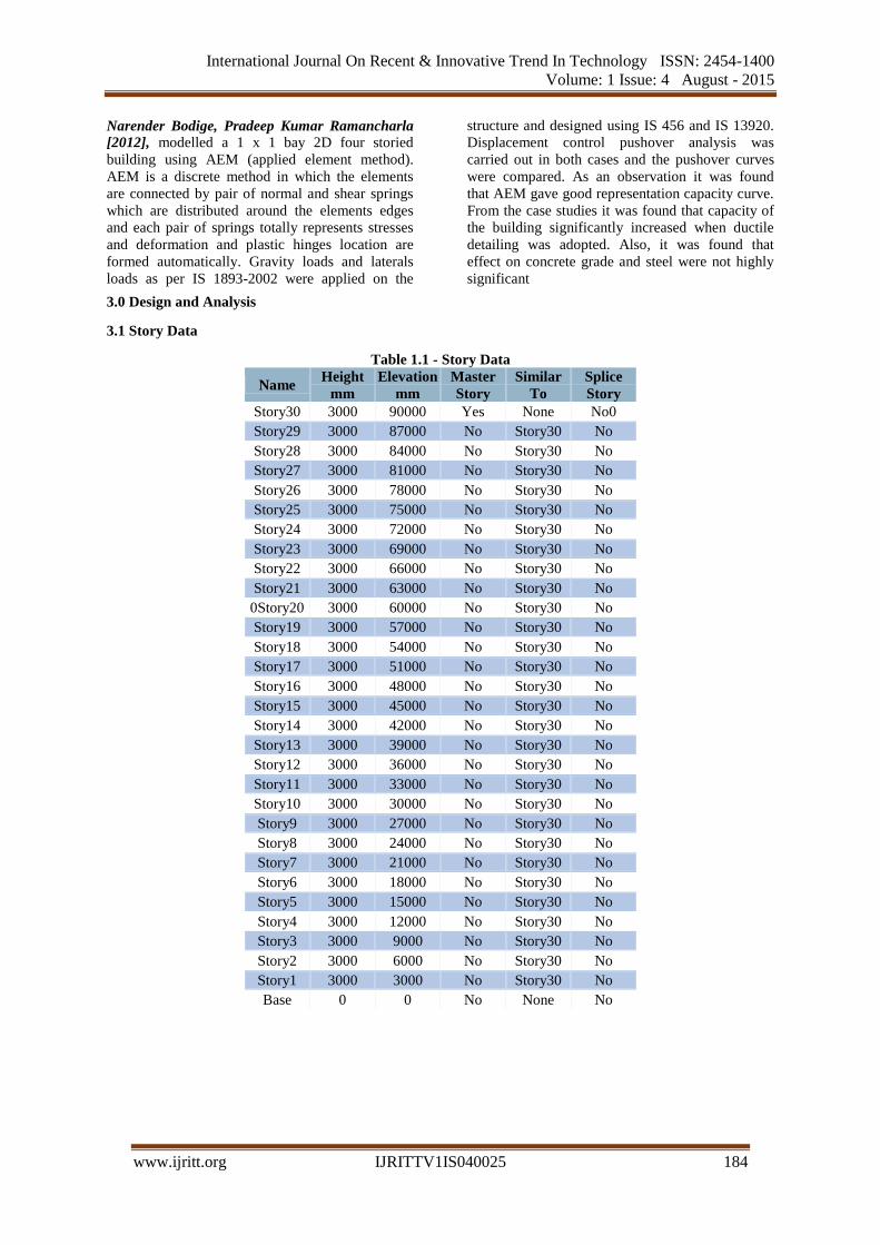
3.0 Design and Analysis
3.1 Story Data
Table 1.1 - Story Data
Name Height
mm
Elevation
mm
Master
Story
Similar
To
Splice
Story
Story30 3000 90000 Yes None No0
Story29 3000 87000 No Story30 No
Story28 3000 84000 No Story30 No
Story27 3000 81000 No Story30 No
Story26 3000 78000 No Story30 No
Story25 3000 75000 No Story30 No
Story24 3000 72000 No Story30 No
Story23 3000 69000 No Story30 No
Story22 3000 66000 No Story30 No
Story21 3000 63000 No Story30 No
0Story20 3000 60000 No Story30 No
Story19 3000 57000 No Story30 No
Story18 3000 54000 No Story30 No
Story17 3000 51000 No Story30 No
Story16 3000 48000 No Story30 No
Story15 3000 45000 No Story30 No
Story14 3000 42000 No Story30 No
Story13 3000 39000 No Story30 No
Story12 3000 36000 No Story30 No
Story11 3000 33000 No Story30 No
Story10 3000 30000 No Story30 No
Story9 3000 27000 No Story30 No
Story8 3000 24000 No Story30 No
Story7 3000 21000 No Story30 No
Story6 3000 18000 No Story30 No
Story5 3000 15000 No Story30 No
Story4 3000 12000 No Story30 No
Story3 3000 9000 No Story30 No
Story2 3000 6000 No Story30 No
Story1 3000 3000 No Story30 No
Base 0 0 No None No
International Journal On Recent & Innovative Trend In Technology ISSN: 2454-1400
Volume: 1 Issue: 4 August - 2015
www.ijritt.org IJRITTV1IS040025 185
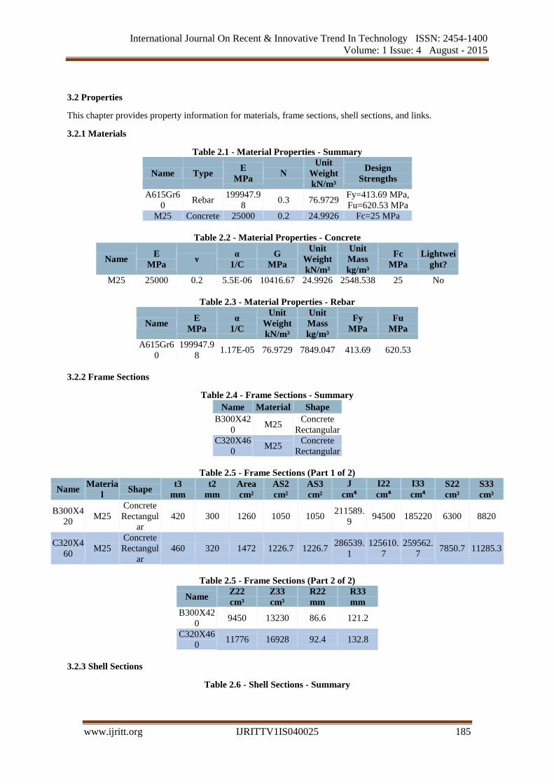
3.2 Properties
This chapter provides property information for materials, frame sections, shell sections, and links.
3.2.1 Materials
Table 2.1 - Material Properties - Summary
Name Type E
MPa Ν
Unit
Weight
kN/m³
Design
Strengths
A615Gr6
0 Rebar
199947.9
8 0.3 76.9729
Fy=413.69 MPa,
Fu=620.53 MPa
M25 Concrete 25000 0.2 24.9926 Fc=25 MPa
Table 2.2 - Material Properties - Concrete
Name E
MPa ν
α
1/C
G
MPa
Unit
Weight
kN/m³
Unit
Mass
kg/m³
Fc
MPa
Lightwei
ght?
M25 25000 0.2 5.5E-06 10416.67 24.9926 2548.538 25 No
Table 2.3 - Material Properties - Rebar
Name E
MPa
α
1/C
Unit
Weight
kN/m³
Unit
Mass
kg/m³
Fy
MPa
Fu
MPa
A615Gr6
0
199947.9
8 1.17E-05 76.9729 7849.047 413.69 620.53
3.2.2 Frame Sections
Table 2.4 - Frame Sections - Summary
Name Material Shape
B300X42
0 M25
Concrete
Rectangular
C320X46
0 M25
Concrete
Rectangular
Table 2.5 - Frame Sections (Part 1 of 2)
Name Materia
l Shape
t3
mm
t2
mm
Area
cm²
AS2
cm²
AS3
cm²
J
cm⁴ I22
cm⁴ I33
cm⁴ S22
cm³
S33
cm³
B300X4
20 M25
Concrete
Rectangul
ar
420 300 1260 1050 1050 211589.
9 94500 185220 6300 8820
C320X4
60 M25
Concrete
Rectangul
ar
460 320 1472 1226.7 1226.7 286539.
1
125610.
7
259562.
7 7850.7 11285.3
Table 2.5 - Frame Sections (Part 2 of 2)
Name Z22
cm³
Z33
cm³
R22
mm
R33
mm
B300X42
0 9450 13230 86.6 121.2
C320X46
0 11776 16928 92.4 132.8
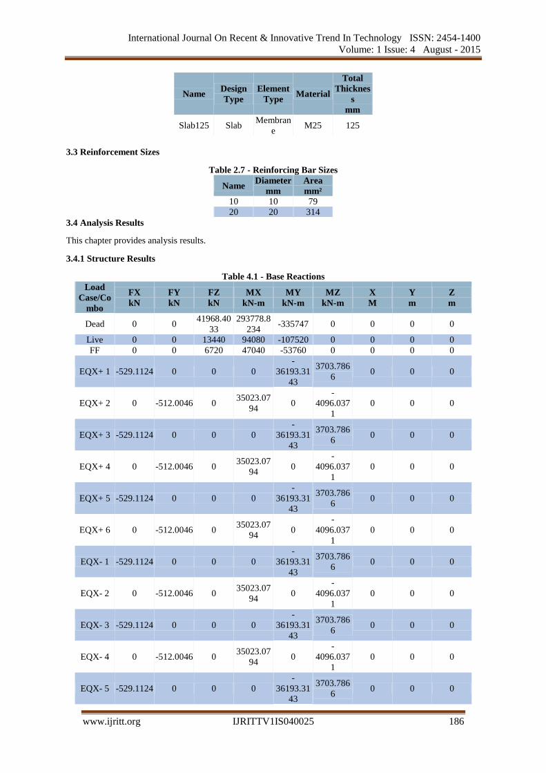
3.2.3 Shell Sections
Table 2.6 - Shell Sections - Summary
International Journal On Recent & Innovative Trend In Technology ISSN: 2454-1400
Volume: 1 Issue: 4 August - 2015
www.ijritt.org IJRITTV1IS040025 186
Name Design
Type
Element
Type Material
Total
Thicknes
s
mm
Slab125 Slab Membran
e M25 125
3.3 Reinforcement Sizes
Table 2.7 - Reinforcing Bar Sizes
Name Diameter
mm
Area
mm²
10 10 79
20 20 314
3.4 Analysis Results
This chapter provides analysis results.
3.4.1 Structure Results
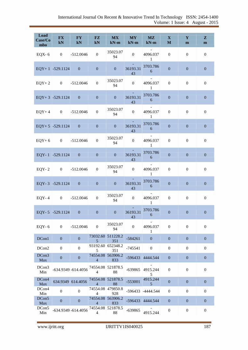
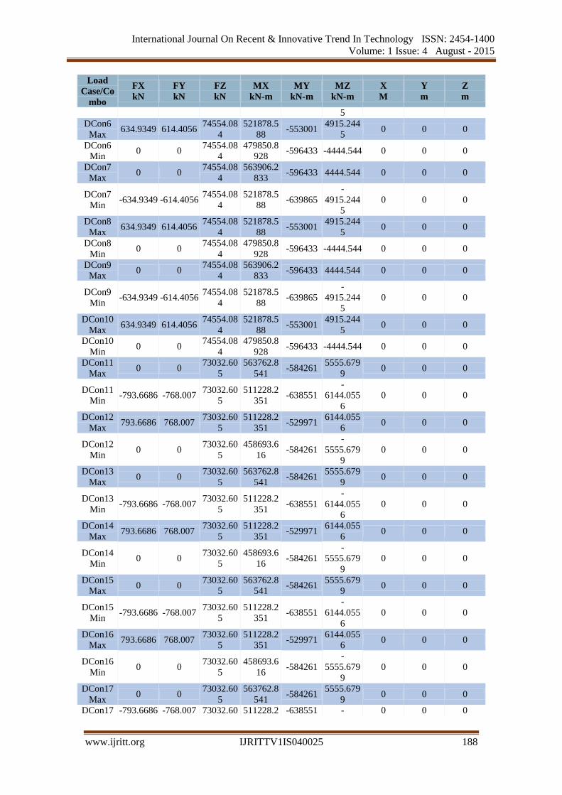
Table 4.1 - Base Reactions
Load
Case/Co
mbo
FX
kN
FY
kN
FZ
kN
MX
kN-m
MY
kN-m
MZ
kN-m
X
M
Y
m
Z
m
Dead 0 0 41968.40
33
293778.8
234 -335747 0 0 0 0
Live 0 0 13440 94080 -107520 0 0 0 0
FF 0 0 6720 47040 -53760 0 0 0 0
EQX+ 1 -529.1124 0 0 0
-
36193.31
43
3703.786
6 0 0 0
EQX+ 2 0 -512.0046 0 35023.07
94 0
-
4096.037
1
0 0 0
EQX+ 3 -529.1124 0 0 0
-
36193.31
43
3703.786
6 0 0 0
EQX+ 4 0 -512.0046 0 35023.07
94 0
-
4096.037
1
0 0 0
EQX+ 5 -529.1124 0 0 0
-
36193.31
43
3703.786
6 0 0 0
EQX+ 6 0 -512.0046 0 35023.07
94 0
-
4096.037
1
0 0 0
EQX- 1 -529.1124 0 0 0
-
36193.31
43
3703.786
6 0 0 0
EQX- 2 0 -512.0046 0 35023.07
94 0
-
4096.037
1
0 0 0
EQX- 3 -529.1124 0 0 0
-
36193.31
43
3703.786
6 0 0 0
EQX- 4 0 -512.0046 0 35023.07
94 0
-
4096.037
1
0 0 0
EQX- 5 -529.1124 0 0 0
-
36193.31
43
3703.786
6 0 0 0
International Journal On Recent & Innovative Trend In Technology ISSN: 2454-1400
Volume: 1 Issue: 4 August - 2015
www.ijritt.org IJRITTV1IS040025 187
Load
Case/Co
mbo
FX
kN
FY
kN
FZ
kN
MX
kN-m
MY
kN-m
MZ
kN-m
X
M
Y
m
Z
m
EQX- 6 0 -512.0046 0 35023.07
94 0
-
4096.037
1
0 0 0
EQY+ 1 -529.1124 0 0 0
-
36193.31
43
3703.786
6 0 0 0
EQY+ 2 0 -512.0046 0 35023.07
94 0
-
4096.037
1
0 0 0
EQY+ 3 -529.1124 0 0 0
-
36193.31
43
3703.786
6 0 0 0
EQY+ 4 0 -512.0046 0 35023.07
94 0
-
4096.037
1
0 0 0
EQY+ 5 -529.1124 0 0 0
-
36193.31
43
3703.786
6 0 0 0
EQY+ 6 0 -512.0046 0 35023.07
94 0
-
4096.037
1
0 0 0
EQY- 1 -529.1124 0 0 0
-
36193.31
43
3703.786
6 0 0 0
EQY- 2 0 -512.0046 0 35023.07
94 0
-
4096.037
1
0 0 0
EQY- 3 -529.1124 0 0 0
-
36193.31
43
3703.786
6 0 0 0
EQY- 4 0 -512.0046 0 35023.07
94 0
-
4096.037
1
0 0 0
EQY- 5 -529.1124 0 0 0
-
36193.31
43
3703.786
6 0 0 0
EQY- 6 0 -512.0046 0 35023.07
94 0
-
4096.037
1
0 0 0
DCon1 0 0 73032.60
5
511228.2
351 -584261 0 0 0 0
DCon2 0 0 93192.60
5
652348.2
351 -745541 0 0 0 0
DCon3
Max 0 0
74554.08
4
563906.2
833 -596433 4444.544 0 0 0
DCon3
Min -634.9349 -614.4056
74554.08
4
521878.5
88 -639865
-
4915.244
5
0 0 0
DCon4
Max 634.9349 614.4056
74554.08
4
521878.5
88 -553001
4915.244
5 0 0 0
DCon4
Min 0 0
74554.08
4
479850.8
928 -596433 -4444.544 0 0 0
DCon5
Max 0 0
74554.08
4
563906.2
833 -596433 4444.544 0 0 0
DCon5
Min -634.9349 -614.4056
74554.08
4
521878.5
88 -639865
-
4915.2440 0 0
International Journal On Recent & Innovative Trend In Technology ISSN: 2454-1400
Volume: 1 Issue: 4 August - 2015
www.ijritt.org IJRITTV1IS040025 188
Load
Case/Co
mbo
FX
kN
FY
kN
FZ
kN
MX
kN-m
MY
kN-m
MZ
kN-m
X
M
Y
m
Z
m
5
DCon6
Max 634.9349 614.4056
74554.08
4
521878.5
88 -553001
4915.244
5 0 0 0
DCon6
Min 0 0
74554.08
4
479850.8
928 -596433 -4444.544 0 0 0
DCon7
Max 0 0
74554.08
4
563906.2
833 -596433 4444.544 0 0 0
DCon7
Min -634.9349 -614.4056
74554.08
4
521878.5
88 -639865
-
4915.244
5
0 0 0
DCon8
Max 634.9349 614.4056
74554.08
4
521878.5
88 -553001
4915.244
5 0 0 0
DCon8
Min 0 0
74554.08
4
479850.8
928 -596433 -4444.544 0 0 0
DCon9
Max 0 0
74554.08
4
563906.2
833 -596433 4444.544 0 0 0
DCon9
Min -634.9349 -614.4056
74554.08
4
521878.5
88 -639865
-
4915.244
5
0 0 0
DCon10
Max 634.9349 614.4056
74554.08
4
521878.5
88 -553001
4915.244
5 0 0 0
DCon10
Min 0 0
74554.08
4
479850.8
928 -596433 -4444.544 0 0 0
DCon11
Max 0 0
73032.60
5
563762.8
541 -584261
5555.679
9 0 0 0
DCon11
Min -793.6686 -768.007
73032.60
5
511228.2
351 -638551
-
6144.055
6
0 0 0
DCon12
Max 793.6686 768.007
73032.60
5
511228.2
351 -529971
6144.055
6 0 0 0
DCon12
Min 0 0
73032.60
5
458693.6
16 -584261
-
5555.679
9
0 0 0
DCon13
Max 0 0
73032.60
5
563762.8
541 -584261
5555.679
9 0 0 0
DCon13
Min -793.6686 -768.007
73032.60
5
511228.2
351 -638551
-
6144.055
6
0 0 0
DCon14
Max 793.6686 768.007
73032.60
5
511228.2
351 -529971
6144.055
6 0 0 0
DCon14
Min 0 0
73032.60
5
458693.6
16 -584261
-
5555.679
9
0 0 0
DCon15
Max 0 0
73032.60
5
563762.8
541 -584261
5555.679
9 0 0 0
DCon15
Min -793.6686 -768.007
73032.60
5
511228.2
351 -638551
-
6144.055
6
0 0 0
DCon16
Max 793.6686 768.007
73032.60
5
511228.2
351 -529971
6144.055
6 0 0 0
DCon16
Min 0 0
73032.60
5
458693.6
16 -584261
-
5555.679
9
0 0 0
DCon17
Max 0 0
73032.60
5
563762.8
541 -584261
5555.679
9 0 0 0
DCon17 -793.6686 -768.007 73032.60 511228.2 -638551 - 0 0 0
International Journal On Recent & Innovative Trend In Technology ISSN: 2454-1400
Volume: 1 Issue: 4 August - 2015
www.ijritt.org IJRITTV1IS040025 189
Load
Case/Co
mbo
FX
kN
FY
kN
FZ
kN
MX
kN-m
MY
kN-m
MZ
kN-m
X
M
Y
m
Z
m
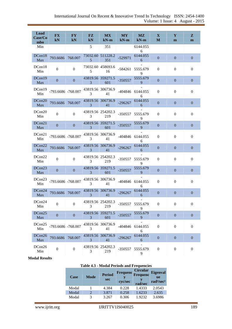
Min 5 351 6144.055
6
DCon18
Max 793.6686 768.007
73032.60
5
511228.2
351 -529971
6144.055
6 0 0 0
DCon18
Min 0 0
73032.60
5
458693.6
16 -584261
-
5555.679
9
0 0 0
DCon19
Max 0 0
43819.56
3
359271.5
601 -350557
5555.679
9 0 0 0
DCon19
Min -793.6686 -768.007
43819.56
3
306736.9
41 -404846
-
6144.055
6
0 0 0
DCon20
Max 793.6686 768.007
43819.56
3
306736.9
41 -296267
6144.055
6 0 0 0
DCon20
Min 0 0
43819.56
3
254202.3
219 -350557
-
5555.679
9
0 0 0
DCon21
Max 0 0
43819.56
3
359271.5
601 -350557
5555.679
9 0 0 0
DCon21
Min -793.6686 -768.007
43819.56
3
306736.9
41 -404846
-
6144.055
6
0 0 0
DCon22
Max 793.6686 768.007
43819.56
3
306736.9
41 -296267
6144.055
6 0 0 0
DCon22
Min 0 0
43819.56
3
254202.3
219 -350557
-
5555.679
9
0 0 0
DCon23
Max 0 0
43819.56
3
359271.5
601 -350557
5555.679
9 0 0 0
DCon23
Min -793.6686 -768.007
43819.56
3
306736.9
41 -404846
-
6144.055
6
0 0 0
DCon24
Max 793.6686 768.007
43819.56
3
306736.9
41 -296267
6144.055
6 0 0 0
DCon24
Min 0 0
43819.56
3
254202.3
219 -350557
-
5555.679
9
0 0 0
DCon25
Max 0 0
43819.56
3
359271.5
601 -350557
5555.679
9 0 0 0
DCon25
Min -793.6686 -768.007
43819.56
3
306736.9
41 -404846
-
6144.055
6
0 0 0
DCon26
Max 793.6686 768.007
43819.56
3
306736.9
41 -296267
6144.055
6 0 0 0
DCon26
Min 0 0
43819.56
3
254202.3
219 -350557
-
5555.679
9
0 0 0
Modal Results
Table 4.3 - Modal Periods and Frequencies
Case Mode Period
sec
Frequenc
y
cyc/sec
Circular
Frequenc
y
rad/sec
Eigenval
ue
rad²/sec²
Modal 1 4.384 0.228 1.4333 2.0543
Modal 2 3.871 0.258 1.6233 2.635
Modal 3 3.267 0.306 1.9232 3.6986
International Journal On Recent & Innovative Trend In Technology ISSN: 2454-1400
Volume: 1 Issue: 4 August - 2015
www.ijritt.org IJRITTV1IS040025 190
Case Mode Period
sec
Frequenc
y
cyc/sec
Circular
Frequenc
y
rad/sec
Eigenval
ue
rad²/sec²
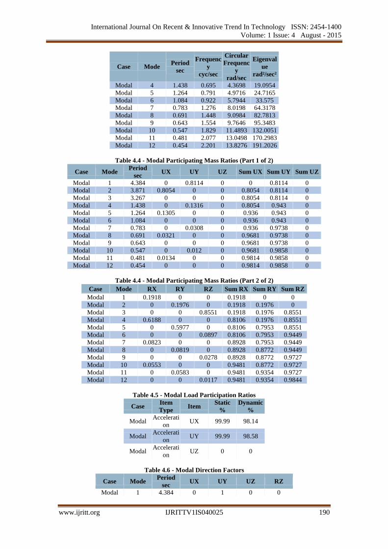
Modal 4 1.438 0.695 4.3698 19.0954
Modal 5 1.264 0.791 4.9716 24.7165
Modal 6 1.084 0.922 5.7944 33.575
Modal 7 0.783 1.276 8.0198 64.3178
Modal 8 0.691 1.448 9.0984 82.7813
Modal 9 0.643 1.554 9.7646 95.3483
Modal 10 0.547 1.829 11.4893 132.0051
Modal 11 0.481 2.077 13.0498 170.2983
Modal 12 0.454 2.201 13.8276 191.2026
Table 4.4 - Modal Participating Mass Ratios (Part 1 of 2)
Case Mode Period
sec UX UY UZ Sum UX Sum UY Sum UZ
Modal 1 4.384 0 0.8114 0 0 0.8114 0
Modal 2 3.871 0.8054 0 0 0.8054 0.8114 0
Modal 3 3.267 0 0 0 0.8054 0.8114 0
Modal 4 1.438 0 0.1316 0 0.8054 0.943 0
Modal 5 1.264 0.1305 0 0 0.936 0.943 0
Modal 6 1.084 0 0 0 0.936 0.943 0
Modal 7 0.783 0 0.0308 0 0.936 0.9738 0
Modal 8 0.691 0.0321 0 0 0.9681 0.9738 0
Modal 9 0.643 0 0 0 0.9681 0.9738 0
Modal 10 0.547 0 0.012 0 0.9681 0.9858 0
Modal 11 0.481 0.0134 0 0 0.9814 0.9858 0
Modal 12 0.454 0 0 0 0.9814 0.9858 0
Table 4.4 - Modal Participating Mass Ratios (Part 2 of 2)
Case Mode RX RY RZ Sum RX Sum RY Sum RZ
Modal 1 0.1918 0 0 0.1918 0 0
Modal 2 0 0.1976 0 0.1918 0.1976 0
Modal 3 0 0 0.8551 0.1918 0.1976 0.8551
Modal 4 0.6188 0 0 0.8106 0.1976 0.8551
Modal 5 0 0.5977 0 0.8106 0.7953 0.8551
Modal 6 0 0 0.0897 0.8106 0.7953 0.9449
Modal 7 0.0823 0 0 0.8928 0.7953 0.9449
Modal 8 0 0.0819 0 0.8928 0.8772 0.9449
Modal 9 0 0 0.0278 0.8928 0.8772 0.9727
Modal 10 0.0553 0 0 0.9481 0.8772 0.9727
Modal 11 0 0.0583 0 0.9481 0.9354 0.9727
Modal 12 0 0 0.0117 0.9481 0.9354 0.9844
Table 4.5 - Modal Load Participation Ratios
Case Item
Type Item
Static
%
Dynamic
%
Modal Accelerati
on UX 99.99 98.14
Modal Accelerati
on UY 99.99 98.58
Modal Accelerati
on UZ 0 0
Table 4.6 - Modal Direction Factors
Case Mode Period
sec UX UY UZ RZ
Modal 1 4.384 0 1 0 0
International Journal On Recent & Innovative Trend In Technology ISSN: 2454-1400
Volume: 1 Issue: 4 August - 2015
www.ijritt.org IJRITTV1IS040025 191
Case Mode Period
sec UX UY UZ RZ
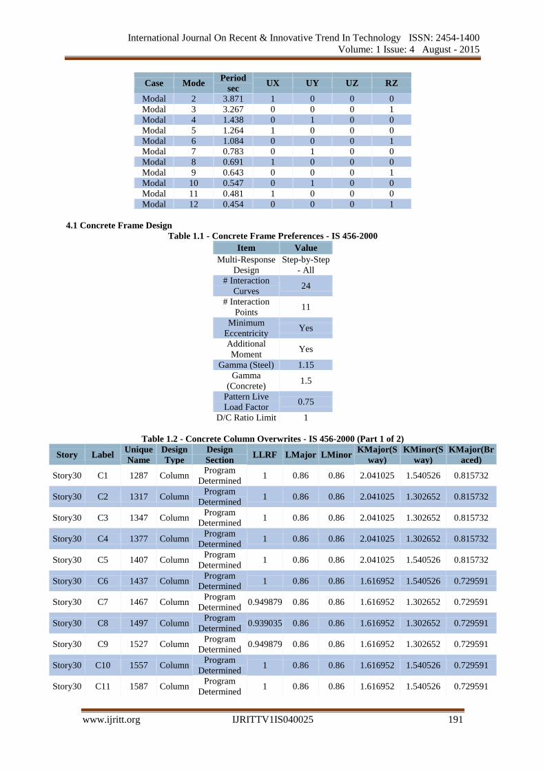
Modal 2 3.871 1 0 0 0
Modal 3 3.267 0 0 0 1
Modal 4 1.438 0 1 0 0
Modal 5 1.264 1 0 0 0
Modal 6 1.084 0 0 0 1
Modal 7 0.783 0 1 0 0
Modal 8 0.691 1 0 0 0
Modal 9 0.643 0 0 0 1
Modal 10 0.547 0 1 0 0
Modal 11 0.481 1 0 0 0
Modal 12 0.454 0 0 0 1
4.1 Concrete Frame Design
Table 1.1 - Concrete Frame Preferences - IS 456-2000
Item Value
Multi-Response
Design
Step-by-Step
- All
# Interaction
Curves 24
# Interaction
Points 11
Minimum
Eccentricity Yes
Additional
Moment Yes
Gamma (Steel) 1.15
Gamma
(Concrete) 1.5
Pattern Live
Load Factor 0.75
D/C Ratio Limit 1
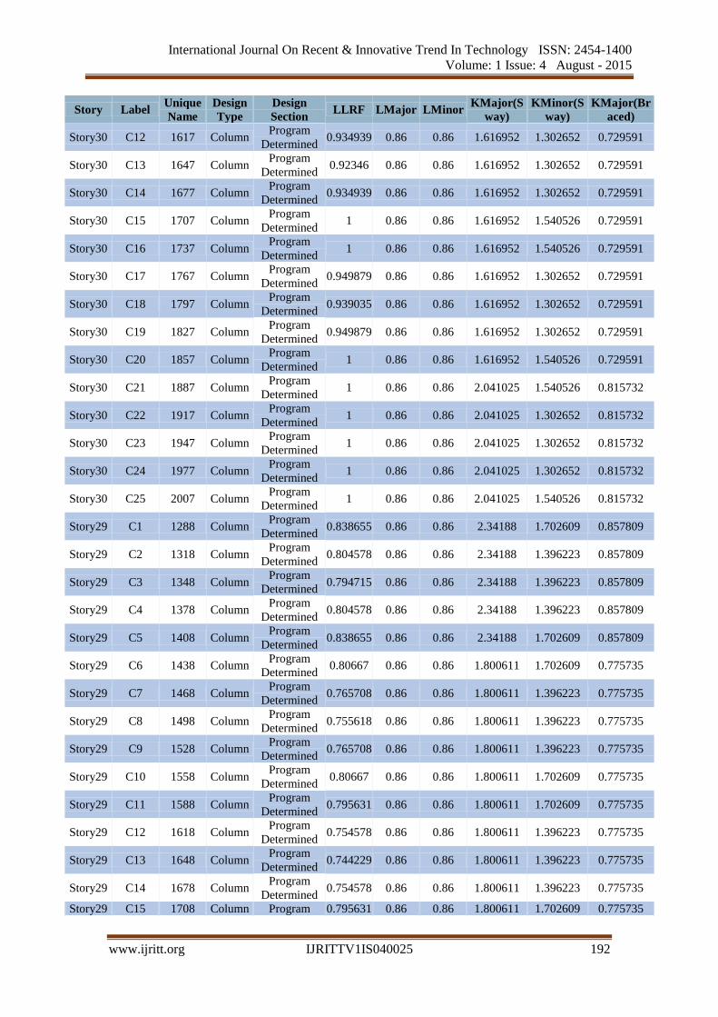
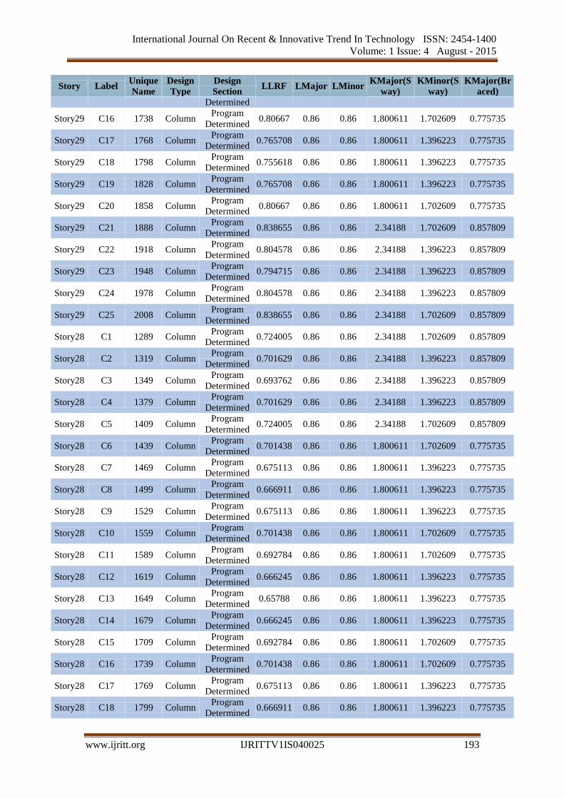
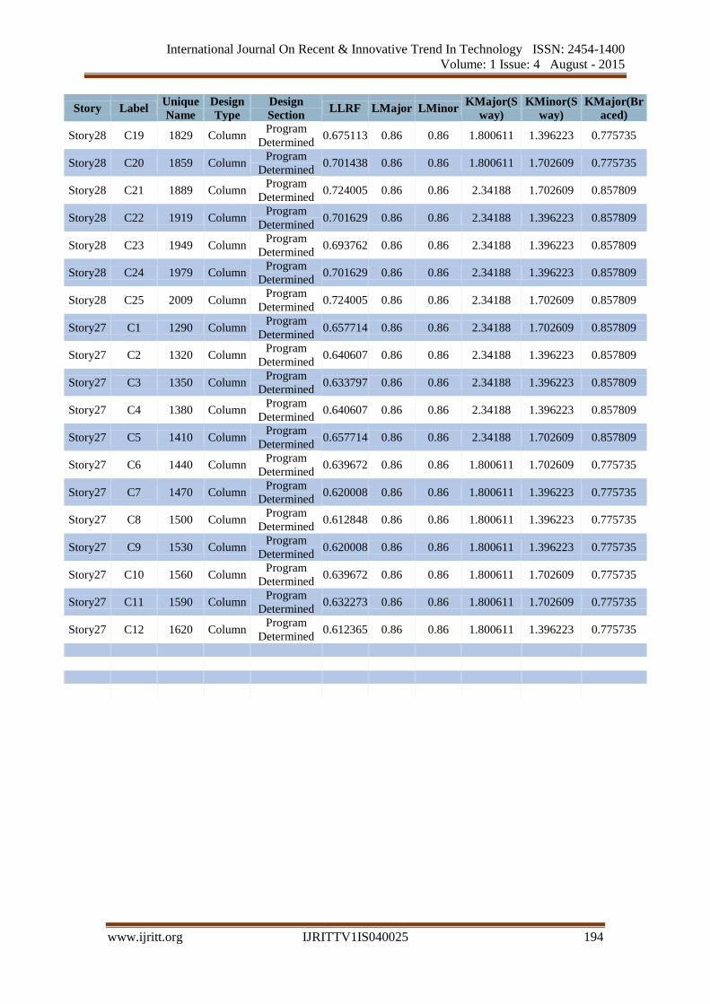
Table 1.2 - Concrete Column Overwrites - IS 456-2000 (Part 1 of 2)
Story Label Unique
Name
Design
Type
Design
Section LLRF LMajor LMinor
KMajor(S
way)
KMinor(S
way)
KMajor(Br
aced)
Story30 C1 1287 Column Program
Determined 1 0.86 0.86 2.041025 1.540526 0.815732
Story30 C2 1317 Column Program
Determined 1 0.86 0.86 2.041025 1.302652 0.815732
Story30 C3 1347 Column Program
Determined 1 0.86 0.86 2.041025 1.302652 0.815732
Story30 C4 1377 Column Program
Determined 1 0.86 0.86 2.041025 1.302652 0.815732
Story30 C5 1407 Column Program
Determined 1 0.86 0.86 2.041025 1.540526 0.815732
Story30 C6 1437 Column Program
Determined 1 0.86 0.86 1.616952 1.540526 0.729591
Story30 C7 1467 Column Program
Determined 0.949879 0.86 0.86 1.616952 1.302652 0.729591
Story30 C8 1497 Column Program
Determined 0.939035 0.86 0.86 1.616952 1.302652 0.729591
Story30 C9 1527 Column Program
Determined 0.949879 0.86 0.86 1.616952 1.302652 0.729591
Story30 C10 1557 Column Program
Determined 1 0.86 0.86 1.616952 1.540526 0.729591
Story30 C11 1587 Column Program
Determined 1 0.86 0.86 1.616952 1.540526 0.729591
International Journal On Recent & Innovative Trend In Technology ISSN: 2454-1400
Volume: 1 Issue: 4 August - 2015
www.ijritt.org IJRITTV1IS040025 192
Story Label Unique
Name
Design
Type
Design
Section LLRF LMajor LMinor
KMajor(S
way)
KMinor(S
way)
KMajor(Br
aced)
Story30 C12 1617 Column Program
Determined 0.934939 0.86 0.86 1.616952 1.302652 0.729591
Story30 C13 1647 Column Program
Determined 0.92346 0.86 0.86 1.616952 1.302652 0.729591
Story30 C14 1677 Column Program
Determined 0.934939 0.86 0.86 1.616952 1.302652 0.729591
Story30 C15 1707 Column Program
Determined 1 0.86 0.86 1.616952 1.540526 0.729591
Story30 C16 1737 Column Program
Determined 1 0.86 0.86 1.616952 1.540526 0.729591
Story30 C17 1767 Column Program
Determined 0.949879 0.86 0.86 1.616952 1.302652 0.729591
Story30 C18 1797 Column Program
Determined 0.939035 0.86 0.86 1.616952 1.302652 0.729591
Story30 C19 1827 Column Program
Determined 0.949879 0.86 0.86 1.616952 1.302652 0.729591
Story30 C20 1857 Column Program
Determined 1 0.86 0.86 1.616952 1.540526 0.729591
Story30 C21 1887 Column Program
Determined 1 0.86 0.86 2.041025 1.540526 0.815732
Story30 C22 1917 Column Program
Determined 1 0.86 0.86 2.041025 1.302652 0.815732
Story30 C23 1947 Column Program
Determined 1 0.86 0.86 2.041025 1.302652 0.815732
Story30 C24 1977 Column Program
Determined 1 0.86 0.86 2.041025 1.302652 0.815732
Story30 C25 2007 Column Program
Determined 1 0.86 0.86 2.041025 1.540526 0.815732
Story29 C1 1288 Column Program
Determined 0.838655 0.86 0.86 2.34188 1.702609 0.857809
Story29 C2 1318 Column Program
Determined 0.804578 0.86 0.86 2.34188 1.396223 0.857809
Story29 C3 1348 Column Program
Determined 0.794715 0.86 0.86 2.34188 1.396223 0.857809
Story29 C4 1378 Column Program
Determined 0.804578 0.86 0.86 2.34188 1.396223 0.857809
Story29 C5 1408 Column Program
Determined 0.838655 0.86 0.86 2.34188 1.702609 0.857809
Story29 C6 1438 Column Program
Determined 0.80667 0.86 0.86 1.800611 1.702609 0.775735
Story29 C7 1468 Column Program
Determined 0.765708 0.86 0.86 1.800611 1.396223 0.775735
Story29 C8 1498 Column Program
Determined 0.755618 0.86 0.86 1.800611 1.396223 0.775735
Story29 C9 1528 Column Program
Determined 0.765708 0.86 0.86 1.800611 1.396223 0.775735
Story29 C10 1558 Column Program
Determined 0.80667 0.86 0.86 1.800611 1.702609 0.775735
Story29 C11 1588 Column Program
Determined 0.795631 0.86 0.86 1.800611 1.702609 0.775735
Story29 C12 1618 Column Program
Determined 0.754578 0.86 0.86 1.800611 1.396223 0.775735
Story29 C13 1648 Column Program
Determined 0.744229 0.86 0.86 1.800611 1.396223 0.775735
Story29 C14 1678 Column Program
Determined 0.754578 0.86 0.86 1.800611 1.396223 0.775735
Story29 C15 1708 Column Program 0.795631 0.86 0.86 1.800611 1.702609 0.775735
International Journal On Recent & Innovative Trend In Technology ISSN: 2454-1400
Volume: 1 Issue: 4 August - 2015
www.ijritt.org IJRITTV1IS040025 193
Story Label Unique
Name
Design
Type
Design
Section LLRF LMajor LMinor
KMajor(S
way)
KMinor(S
way)
KMajor(Br
aced)
Determined
Story29 C16 1738 Column Program
Determined 0.80667 0.86 0.86 1.800611 1.702609 0.775735
Story29 C17 1768 Column Program
Determined 0.765708 0.86 0.86 1.800611 1.396223 0.775735
Story29 C18 1798 Column Program
Determined 0.755618 0.86 0.86 1.800611 1.396223 0.775735
Story29 C19 1828 Column Program
Determined 0.765708 0.86 0.86 1.800611 1.396223 0.775735
Story29 C20 1858 Column Program
Determined 0.80667 0.86 0.86 1.800611 1.702609 0.775735
Story29 C21 1888 Column Program
Determined 0.838655 0.86 0.86 2.34188 1.702609 0.857809
Story29 C22 1918 Column Program
Determined 0.804578 0.86 0.86 2.34188 1.396223 0.857809
Story29 C23 1948 Column Program
Determined 0.794715 0.86 0.86 2.34188 1.396223 0.857809
Story29 C24 1978 Column Program
Determined 0.804578 0.86 0.86 2.34188 1.396223 0.857809
Story29 C25 2008 Column Program
Determined 0.838655 0.86 0.86 2.34188 1.702609 0.857809
Story28 C1 1289 Column Program
Determined 0.724005 0.86 0.86 2.34188 1.702609 0.857809
Story28 C2 1319 Column Program
Determined 0.701629 0.86 0.86 2.34188 1.396223 0.857809
Story28 C3 1349 Column Program
Determined 0.693762 0.86 0.86 2.34188 1.396223 0.857809
Story28 C4 1379 Column Program
Determined 0.701629 0.86 0.86 2.34188 1.396223 0.857809
Story28 C5 1409 Column Program
Determined 0.724005 0.86 0.86 2.34188 1.702609 0.857809
Story28 C6 1439 Column Program
Determined 0.701438 0.86 0.86 1.800611 1.702609 0.775735
Story28 C7 1469 Column Program
Determined 0.675113 0.86 0.86 1.800611 1.396223 0.775735
Story28 C8 1499 Column Program
Determined 0.666911 0.86 0.86 1.800611 1.396223 0.775735
Story28 C9 1529 Column Program
Determined 0.675113 0.86 0.86 1.800611 1.396223 0.775735
Story28 C10 1559 Column Program
Determined 0.701438 0.86 0.86 1.800611 1.702609 0.775735
Story28 C11 1589 Column Program
Determined 0.692784 0.86 0.86 1.800611 1.702609 0.775735
Story28 C12 1619 Column Program
Determined 0.666245 0.86 0.86 1.800611 1.396223 0.775735
Story28 C13 1649 Column Program
Determined 0.65788 0.86 0.86 1.800611 1.396223 0.775735
Story28 C14 1679 Column Program
Determined 0.666245 0.86 0.86 1.800611 1.396223 0.775735
Story28 C15 1709 Column Program
Determined 0.692784 0.86 0.86 1.800611 1.702609 0.775735
Story28 C16 1739 Column Program
Determined 0.701438 0.86 0.86 1.800611 1.702609 0.775735
Story28 C17 1769 Column Program
Determined 0.675113 0.86 0.86 1.800611 1.396223 0.775735
Story28 C18 1799 Column Program
Determined 0.666911 0.86 0.86 1.800611 1.396223 0.775735
International Journal On Recent & Innovative Trend In Technology ISSN: 2454-1400
Volume: 1 Issue: 4 August - 2015
www.ijritt.org IJRITTV1IS040025 194
Story Label Unique
Name
Design
Type
Design
Section LLRF LMajor LMinor
KMajor(S
way)
KMinor(S
way)
KMajor(Br
aced)
Story28 C19 1829 Column Program
Determined 0.675113 0.86 0.86 1.800611 1.396223 0.775735
Story28 C20 1859 Column Program
Determined 0.701438 0.86 0.86 1.800611 1.702609 0.775735
Story28 C21 1889 Column Program
Determined 0.724005 0.86 0.86 2.34188 1.702609 0.857809
Story28 C22 1919 Column Program
Determined 0.701629 0.86 0.86 2.34188 1.396223 0.857809
Story28 C23 1949 Column Program
Determined 0.693762 0.86 0.86 2.34188 1.396223 0.857809
Story28 C24 1979 Column Program
Determined 0.701629 0.86 0.86 2.34188 1.396223 0.857809
Story28 C25 2009 Column Program
Determined 0.724005 0.86 0.86 2.34188 1.702609 0.857809
Story27 C1 1290 Column Program
Determined 0.657714 0.86 0.86 2.34188 1.702609 0.857809
Story27 C2 1320 Column Program
Determined 0.640607 0.86 0.86 2.34188 1.396223 0.857809
Story27 C3 1350 Column Program
Determined 0.633797 0.86 0.86 2.34188 1.396223 0.857809
Story27 C4 1380 Column Program
Determined 0.640607 0.86 0.86 2.34188 1.396223 0.857809
Story27 C5 1410 Column Program
Determined 0.657714 0.86 0.86 2.34188 1.702609 0.857809
Story27 C6 1440 Column Program
Determined 0.639672 0.86 0.86 1.800611 1.702609 0.775735
Story27 C7 1470 Column Program
Determined 0.620008 0.86 0.86 1.800611 1.396223 0.775735
Story27 C8 1500 Column Program
Determined 0.612848 0.86 0.86 1.800611 1.396223 0.775735
Story27 C9 1530 Column Program
Determined 0.620008 0.86 0.86 1.800611 1.396223 0.775735
Story27 C10 1560 Column Program
Determined 0.639672 0.86 0.86 1.800611 1.702609 0.775735
Story27 C11 1590 Column Program
Determined 0.632273 0.86 0.86 1.800611 1.702609 0.775735
Story27 C12 1620 Column Program
Determined 0.612365 0.86 0.86 1.800611 1.396223 0.775735
International Journal On Recent & Innovative Trend In Technology ISSN: 2454-1400
Volume: 1 Issue: 4 August - 2015
www.ijritt.org IJRITTV1IS040025 195
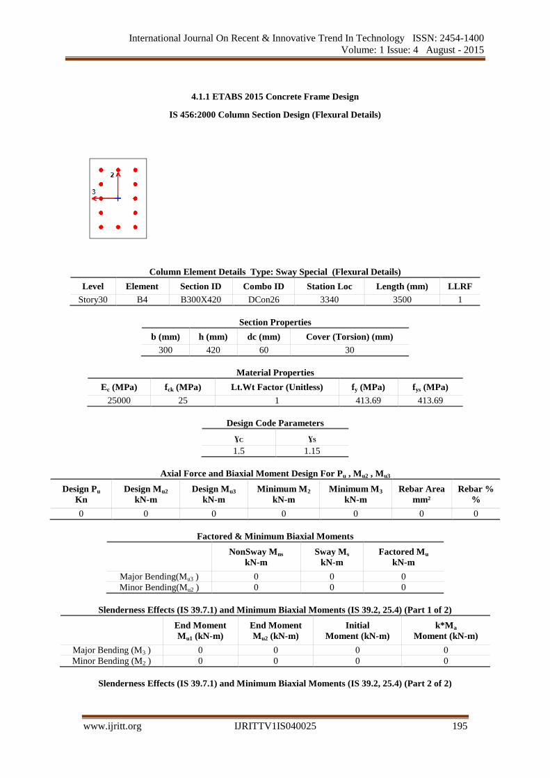
4.1.1 ETABS 2015 Concrete Frame Design
IS 456:2000 Column Section Design (Flexural Details)
Column Element Details Type: Sway Special (Flexural Details)
Level Element Section ID Combo ID Station Loc Length (mm) LLRF
Story30 B4 B300X420 DCon26 3340 3500 1
Section Properties
b (mm) h (mm) dc (mm) Cover (Torsion) (mm)
300 420 60 30
Material Properties
Ec (MPa) fck (MPa) Lt.Wt Factor (Unitless) fy (MPa) fys (MPa)
25000 25 1 413.69 413.69
Design Code Parameters
ɣC ɣS
1.5 1.15
Axial Force and Biaxial Moment Design For Pu , Mu2 , Mu3
Design Pu
Kn
Design Mu2
kN-m
Design Mu3
kN-m
Minimum M2
kN-m
Minimum M3
kN-m
Rebar Area
mm²
Rebar %
%
0 0 0 0 0 0 0
Factored & Minimum Biaxial Moments
NonSway Mns
kN-m
Sway Ms
kN-m
Factored Mu
kN-m
Major Bending(Mu3 ) 0 0 0
Minor Bending(Mu2 ) 0 0 0
Slenderness Effects (IS 39.7.1) and Minimum Biaxial Moments (IS 39.2, 25.4) (Part 1 of 2)
End Moment
Mu1 (kN-m)
End Moment
Mu2 (kN-m)
Initial
Moment (kN-m)
k*Ma
Moment (kN-m)
Major Bending (M3 ) 0 0 0 0
Minor Bending (M2 ) 0 0 0 0
Slenderness Effects (IS 39.7.1) and Minimum Biaxial Moments (IS 39.2, 25.4) (Part 2 of 2)
International Journal On Recent & Innovative Trend In Technology ISSN: 2454-1400
Volume: 1 Issue: 4 August - 2015
www.ijritt.org IJRITTV1IS040025 196
Minimum
Moment (kN-m)
Minimum
Eccentricity (mm)
0 0
0 0
Effective Length Factors (IS 25.2, Annex E)
K
Sway
K
Non-Sway
Framing
Type
P-Delta
Done?
Q
Factor
K
Used
Major Bend(M3 ) 0 0 Sway Special No 0 0
Minor Bend(M2 ) 0 0 Sway Special No 0 0
Additional Moment Reduction Factor k (IS 39.7.1.1)
Ag
cm²
Asc
cm²
Puz
kN
Pb
Kn
Pu
kN
k
Unitless
0 0 0 0 0 0
Additional Moment (IS 39.7.1) (Part 1 of 2)
Consider
Ma
Length
Factor
Section
Depth (mm)
KL/Depth
Ratio
KL/Depth
Limit
KL/Depth
Exceeded
Major Bending (M3 ) Yes 0 0 0 0 No
Minor Bending (M2 ) Yes 0 0 0 0 No
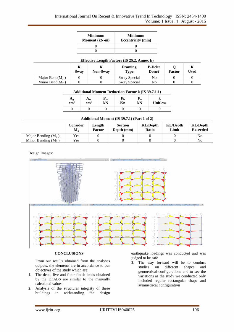
Design Images:
CONCLUSIONS
From our results obtained from the analyses
outputs, the elements are in accordance to our
objectives of the study which are:
1. The dead, live and floor finish loads obtained
by the ETABS are similar to the manually
calculated values
2. Analysis of the structural integrity of these
buildings in withstanding the design
earthquake loadings was conducted and was
judged to be safe 3. The way forward will be to conduct
studies on different shapes and
geometrical configurations and to see the
variations as the study we conducted only
included regular rectangular shape and
symmetrical configuration
International Journal On Recent & Innovative Trend In Technology ISSN: 2454-1400
Volume: 1 Issue: 4 August - 2015
www.ijritt.org IJRITTV1IS040025 197
REFERENCES
[1] ACI Committee 318. (2002) Building code requirements
for reinforced concrete (ACI 318-02). American Concrete
Institute, Detroit, MI [2] AISC.(2002) Seismic provisions for structural steel
buildings. (Chicago (IL): American Institute of Steel Construction. Aristizabal-Ochoa, J.D. (1986). Disposable
knee bracing: improvement in seismic design of steel
frames. Journal of Structural Engineering, 112 (7): 1544-1552.
[3] Abou-Elfath, H. & Ghobarah, A. (2000). Behaviour of
reinforced concrete frames rehabilitated with concentric steel bracing. Canadian Journal of Civil Engineering. 27
433-444.
[4 Balendra, T., Yu, C.Y., & Xiao, Y. (2001). An economical structural system for wind and earthquake loads.
Engineering Structures, 23: 491-501.
[5] Badoux, M. & Jirsa, O. (1990). Steel bracing of RC frames for seismic retrofitting. Journal of Structural Enineering.
ASCE, No. 1, 116, 55-74.