Embed Size (px)
Citation preview
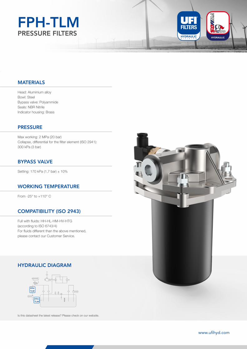
FPH-TLMPRESSURE FILTERS
FPHTLM
FPHTLM
113
FPH-TLMPRESSURE FILTERS
Head: Aluminium alloyBowl: SteelBypass valve: PolyammideSeals: NBR NitrileIndicator housing: Brass
Max working: 2 MPa (20 bar)Collapse, differential for the filter element (ISO 2941): 300 kPa (3 bar)
From -25° to +110° C
Setting: 170 kPa (1,7 bar) ± 10%
MATERIALS
PRESSURE
WORKING TEMPERATURE
BYPASS VALVE
Full with fluids: HH-HL-HM-HV-HTG(according to ISO 6743/4)For fluids different than the above mentioned,please contact our Customer Service.
Is this datasheet the latest release? Please check on our website.
COMPATIBILITY (ISO 2943)
HYDRAULIC DIAGRAM
www.ufihyd.com
114
FPHPRESSURE FILTERS
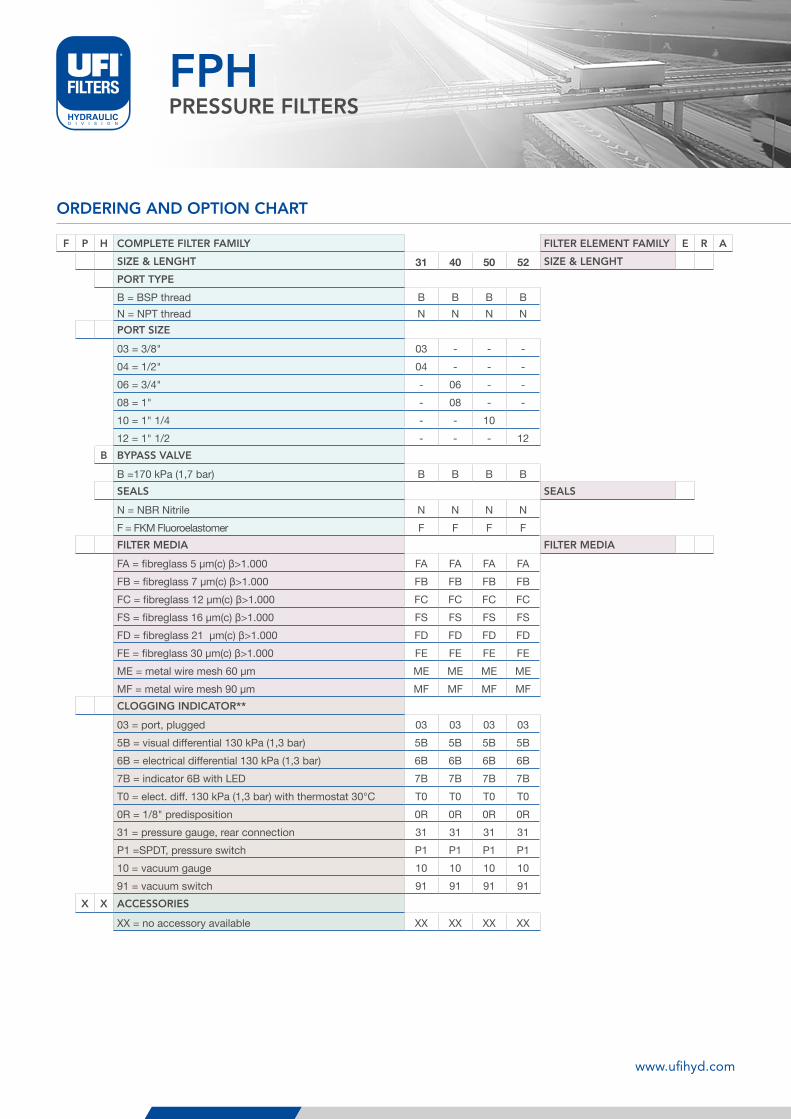
ORDERING AND OPTION CHART
F P H COMPLETE FILTER FAMILY FILTER ELEMENT FAMILY E R A
SIZE & LENGHT 31 40 50 52 SIZE & LENGHT
PORT TYPE
B = BSP thread B B B BN = NPT thread N N N NPORT SIZE
03 = 3/8" 03 - - -04 = 1/2" 04 - - -06 = 3/4" - 06 - -08 = 1" - 08 - -10 = 1" 1/4 - - 1012 = 1" 1/2 - - - 12
B BYPASS VALVE
B =170 kPa (1,7 bar) B B B BSEALS SEALS
N = NBR Nitrile N N N NF = FKM Fluoroelastomer F F F FFILTER MEDIA FILTER MEDIA
FA = fibreglass 5 µm(c) β>1.000 FA FA FA FAFB = fibreglass 7 µm(c) β>1.000 FB FB FB FBFC = fibreglass 12 µm(c) β>1.000 FC FC FC FCFS = fibreglass 16 µm(c) β>1.000 FS FS FS FSFD = fibreglass 21 µm(c) β>1.000 FD FD FD FDFE = fibreglass 30 µm(c) β>1.000 FE FE FE FEME = metal wire mesh 60 µm ME ME ME MEMF = metal wire mesh 90 µm MF MF MF MFCLOGGING INDICATOR**
03 = port, plugged 03 03 03 035B = visual differential 130 kPa (1,3 bar) 5B 5B 5B 5B6B = electrical differential 130 kPa (1,3 bar) 6B 6B 6B 6B7B = indicator 6B with LED 7B 7B 7B 7BT0 = elect. diff. 130 kPa (1,3 bar) with thermostat 30°C T0 T0 T0 T00R = 1/8" predisposition 0R 0R 0R 0R31 = pressure gauge, rear connection 31 31 31 31P1 =SPDT, pressure switch P1 P1 P1 P110 = vacuum gauge 10 10 10 1091 = vacuum switch 91 91 91 91
X X ACCESSORIES
XX = no accessory available XX XX XX XX
www.ufihyd.com
115
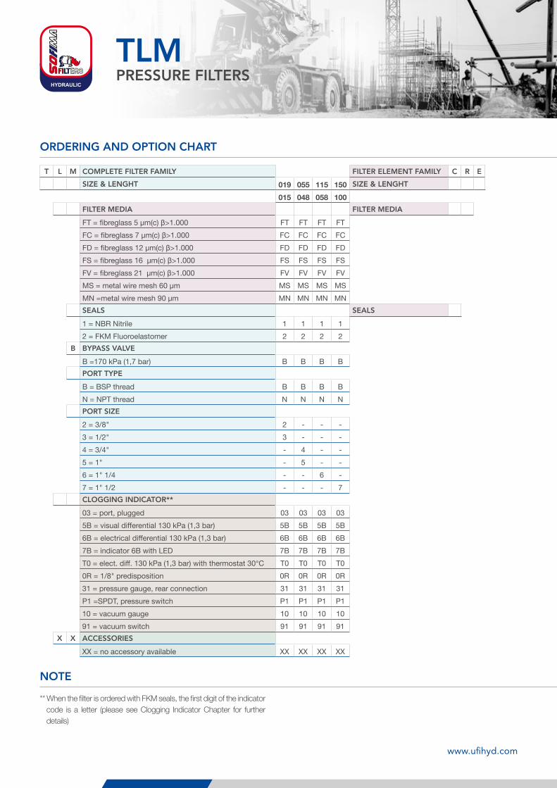
ORDERING AND OPTION CHART
TLMPRESSURE FILTERS
T L M COMPLETE FILTER FAMILY FILTER ELEMENT FAMILY C R E
SIZE & LENGHT 019 055 115 150 SIZE & LENGHT
015 048 058 100FILTER MEDIA FILTER MEDIA
FT = fibreglass 5 µm(c) β>1.000 FT FT FT FTFC = fibreglass 7 µm(c) β>1.000 FC FC FC FCFD = fibreglass 12 µm(c) β>1.000 FD FD FD FDFS = fibreglass 16 µm(c) β>1.000 FS FS FS FSFV = fibreglass 21 µm(c) β>1.000 FV FV FV FVMS = metal wire mesh 60 µm MS MS MS MSMN =metal wire mesh 90 µm MN MN MN MNSEALS SEALS
1 = NBR Nitrile 1 1 1 12 = FKM Fluoroelastomer 2 2 2 2
B BYPASS VALVE
B =170 kPa (1,7 bar) B B B BPORT TYPE
B = BSP thread B B B BN = NPT thread N N N NPORT SIZE
2 = 3/8" 2 - - -3 = 1/2" 3 - - -4 = 3/4" - 4 - -5 = 1" - 5 - -6 = 1" 1/4 - - 6 -7 = 1" 1/2 - - - 7CLOGGING INDICATOR**
03 = port, plugged 03 03 03 035B = visual differential 130 kPa (1,3 bar) 5B 5B 5B 5B6B = electrical differential 130 kPa (1,3 bar) 6B 6B 6B 6B7B = indicator 6B with LED 7B 7B 7B 7BT0 = elect. diff. 130 kPa (1,3 bar) with thermostat 30°C T0 T0 T0 T00R = 1/8" predisposition 0R 0R 0R 0R31 = pressure gauge, rear connection 31 31 31 31P1 =SPDT, pressure switch P1 P1 P1 P110 = vacuum gauge 10 10 10 1091 = vacuum switch 91 91 91 91
X X ACCESSORIES
XX = no accessory available XX XX XX XX
NOTE
** When the filter is ordered with FKM seals, the first digit of the indicator code is a letter (please see Clogging Indicator Chapter for further details)
www.ufihyd.com
E
H1
D2
H3
H4
E1E
4
E3
D1
D1
H4
E2
D3
E2
R
FPH
E
H1
D2
H3
H4
E1
E4
E3
D1
D1
H4
E2
D3
E2
R
FPH116
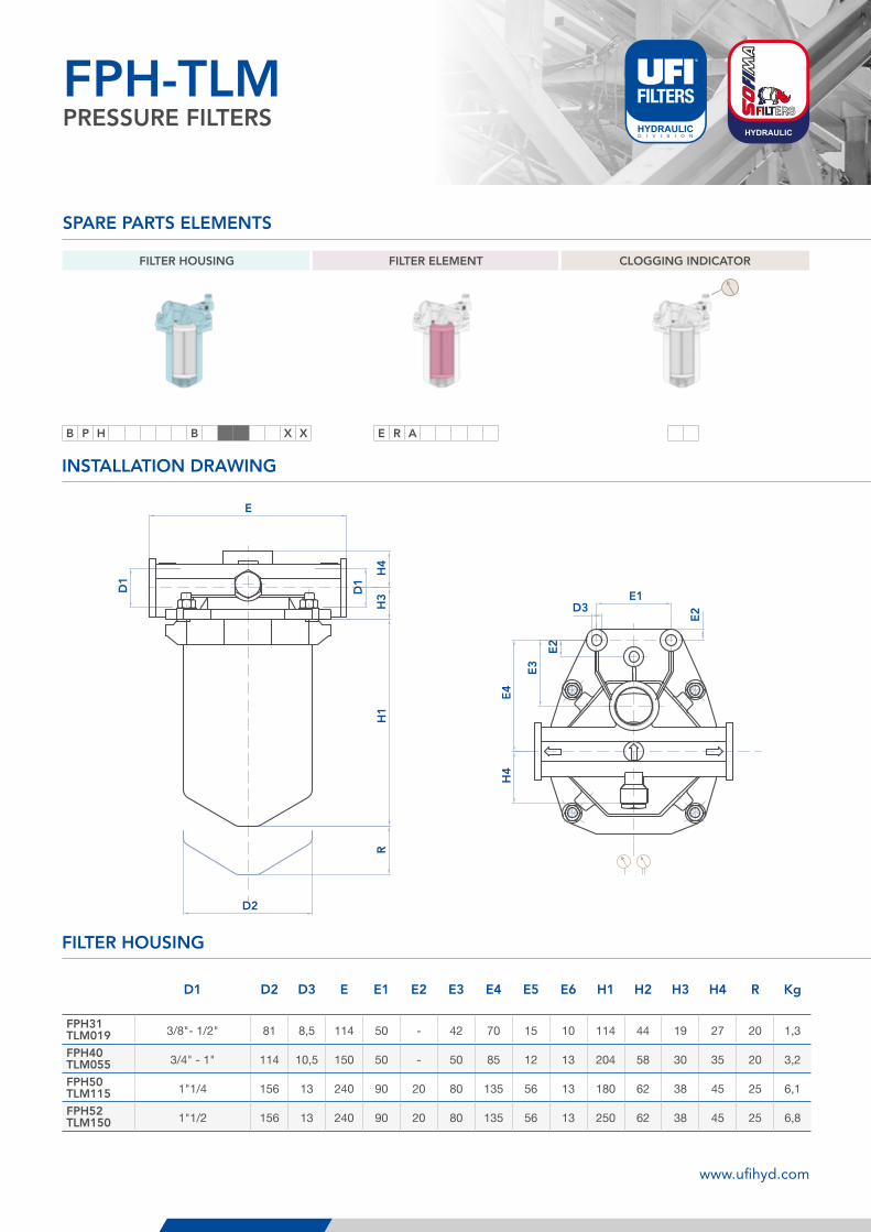
FILTER HOUSING FILTER ELEMENT CLOGGING INDICATOR
B P H B X X E R A
SPARE PARTS ELEMENTS
FPH-TLMPRESSURE FILTERS
FILTER HOUSING
INSTALLATION DRAWING
D1 D2 D3 E E1 E2 E3 E4 E5 E6 H1 H2 H3 H4 R Kg
FPH31TLM019 3/8"- 1/2" 81 8,5 114 50 - 42 70 15 10 114 44 19 27 20 1,3
FPH40TLM055 3/4" - 1" 114 10,5 150 50 - 50 85 12 13 204 58 30 35 20 3,2
FPH50TLM115 1"1/4 156 13 240 90 20 80 135 56 13 180 62 38 45 25 6,1
FPH52TLM150 1"1/2 156 13 240 90 20 80 135 56 13 250 62 38 45 25 6,8
www.ufihyd.com
117
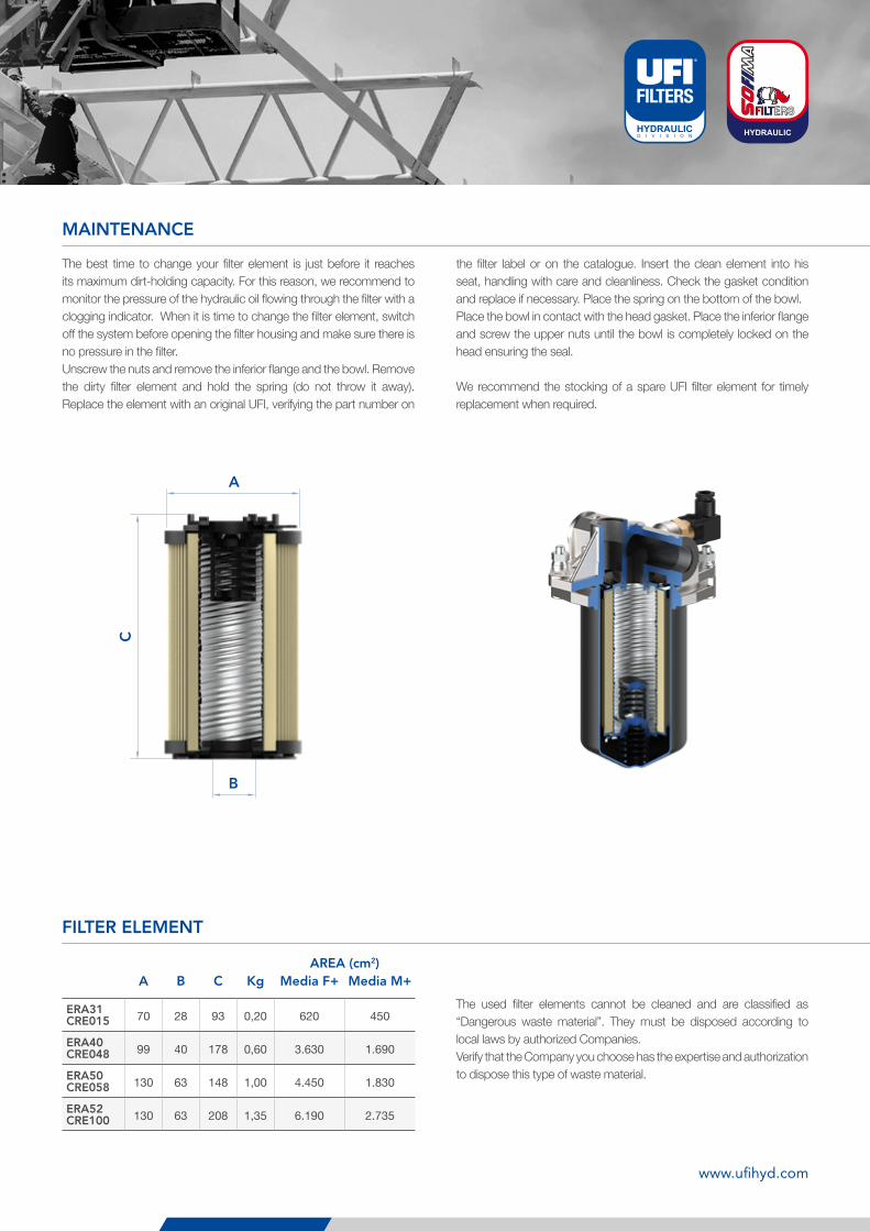
MAINTENANCE
The best time to change your filter element is just before it reaches its maximum dirt-holding capacity. For this reason, we recommend to monitor the pressure of the hydraulic oil flowing through the filter with a clogging indicator. When it is time to change the filter element, switch off the system before opening the filter housing and make sure there is no pressure in the filter. Unscrew the nuts and remove the inferior flange and the bowl. Remove the dirty filter element and hold the spring (do not throw it away). Replace the element with an original UFI, verifying the part number on
the filter label or on the catalogue. Insert the clean element into his seat, handling with care and cleanliness. Check the gasket condition and replace if necessary. Place the spring on the bottom of the bowl.Place the bowl in contact with the head gasket. Place the inferior flange and screw the upper nuts until the bowl is completely locked on the head ensuring the seal.
We recommend the stocking of a spare UFI filter element for timely replacement when required.
A
B
C
FILTER ELEMENT
The used filter elements cannot be cleaned and are classified as “Dangerous waste material”. They must be disposed according to local laws by authorized Companies.Verify that the Company you choose has the expertise and authorization to dispose this type of waste material.
AREA (cm2)A B C Kg Media F+ Media M+
ERA31CRE015 70 28 93 0,20 620 450
ERA40CRE048 99 40 178 0,60 3.630 1.690
ERA50CRE058 130 63 148 1,00 4.450 1.830
ERA52CRE100 130 63 208 1,35 6.190 2.735
www.ufihyd.com
118
FPH-TLMPRESSURE FILTERS
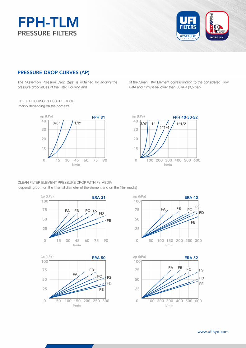
PRESSURE DROP CURVES (ΔP)
The “Assembly Pressure Drop (Δp)” is obtained by adding the pressure drop values of the Filter Housing and
of the Clean Filter Element corresponding to the considered Flow Rate and it must be lower than 50 kPa (0,5 bar).
FILTER HOUSING PRESSURE DROP(mainly depending on the port size)
CLEAN FILTER ELEMENT PRESSURE DROP WITH F+ MEDIA(depending both on the internal diameter of the element and on the filter media)
Recommended range
800
750
700
650
600
550
500
450
400
350
300
250
200
150
100
50
01/2”3/8” 3/4” 1” 1” 1/4 1” 1/2
5 <
v <
10
m/s
1000 200 400 500 600
10
20
30
40
300150 30 60 75 90
10
20
30
40
45
Δp (kPa)
l/min
Δp (kPa)
l/min
FLO
W R
ATE
[l/
min
]PORT SIZE
3/4"1” 1/4
3/8" 1/2” 1” 1/2 1"
FPH 40-50-52FPH 31
FPH 1PRESSURE FILTERS
250 50 75 100 125 150
100
200
300
400
1000 200 300 400 500 600
100
200
300
400
150 30 60 75 90
25
50
75
100
45 500 100 200 250 300
25
50
75
100
150
500 100 200 250 300
25
50
75
100
150 1000 200 400 500 600
25
50
75
100
300
l/min
Δp (kPa)
l/min
Δp (kPa)
Δp (kPa)
l/min
Δp (kPa)
l/min
Δp (kPa)
l/min
Δp (kPa)
l/min
FA FB FCFD
FE
FS FA FB FCFD
FE
FS
FAFB
FC
FD
FE
FS
FA FB FC
FD
FS
FE
FPH 31 FPH 40-50-52
ERA 31 ERA 40
ERA 50 ERA 52
FPH 2PRESSURE FILTERS
www.ufihyd.com
119
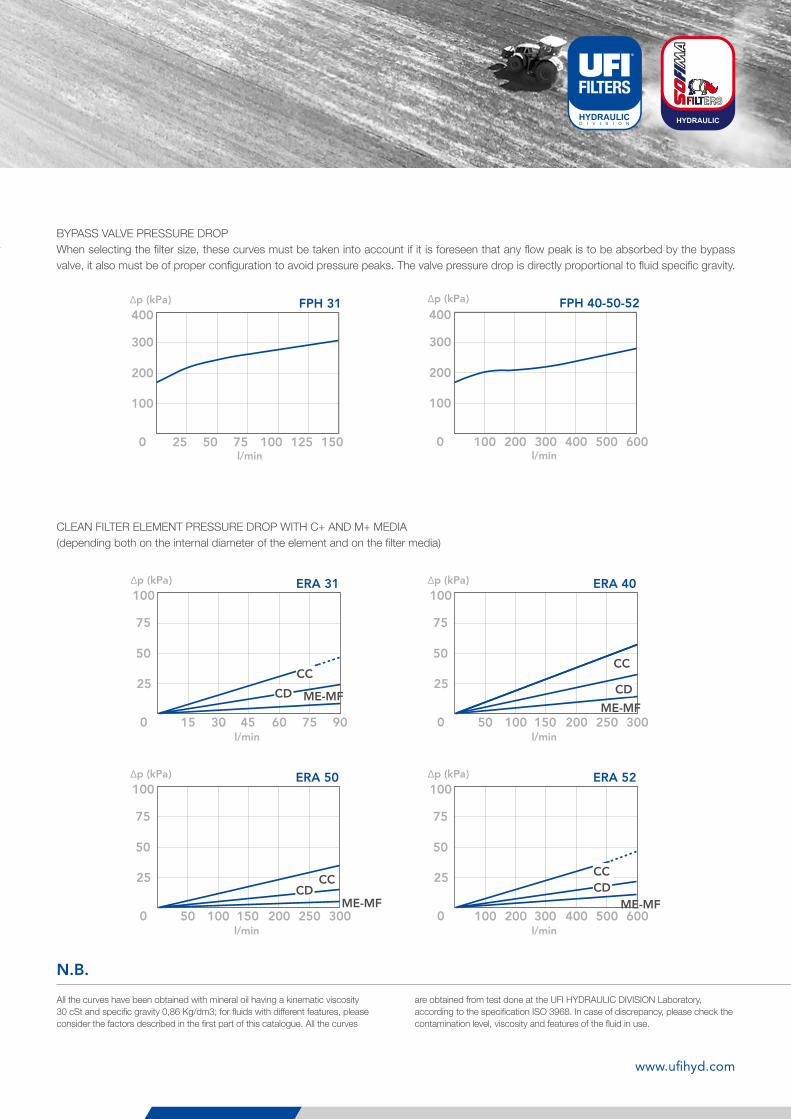
All the curves have been obtained with mineral oil having a kinematic viscosity 30 cSt and specific gravity 0,86 Kg/dm3; for fluids with different features, please consider the factors described in the first part of this catalogue. All the curves
are obtained from test done at the UFI HYDRAULIC DIVISION Laboratory, according to the specification ISO 3968. In case of discrepancy, please check the contamination level, viscosity and features of the fluid in use.
N.B.
250 50 75 100 125 150
100
200
300
400
1000 200 300 400 500 600
100
200
300
400
150 30 60 75 90
25
50
75
100
45 500 100 200 250 300
25
50
75
100
150
500 100 200 250 300
25
50
75
100
150 1000 200 400 500 600
25
50
75
100
300
l/min
Δp (kPa)
l/min
Δp (kPa)
Δp (kPa)
l/min
Δp (kPa)
l/min
Δp (kPa)
l/min
Δp (kPa)
l/min
FA FB FCFD
FE
FS FA FB FCFD
FE
FS
FAFB
FC
FD
FE
FS
FA FB FC
FD
FS
FE
FPH 31 FPH 40-50-52
ERA 31 ERA 40
ERA 50 ERA 52
FPH 2PRESSURE FILTERS
BYPASS VALVE PRESSURE DROPWhen selecting the filter size, these curves must be taken into account if it is foreseen that any flow peak is to be absorbed by the bypass valve, it also must be of proper configuration to avoid pressure peaks. The valve pressure drop is directly proportional to fluid specific gravity.
250 50 75 100 125 150
100
200
300
400
1000 200 300 400 500 600
100
200
300
400
150 30 60 75 90
25
50
75
100
45 500 100 200 250 300
25
50
75
100
150
500 100 200 250 300
25
50
75
100
150 1000 200 400 500 600
25
50
75
100
300
l/min
Δp (kPa)
l/min
Δp (kPa)
Δp (kPa)
l/min
Δp (kPa)
l/min
Δp (kPa)
l/min
Δp (kPa)
l/min
CC
CD
CC
CD
CCCD
CCCD
ME-MF
ME-MF
ME-MF
ME-MF
FPH 31 FPH 40-50-52
ERA 31 ERA 40
ERA 50 ERA 52
FPH 3PRESSURE FILTERS
CLEAN FILTER ELEMENT PRESSURE DROP WITH C+ AND M+ MEDIA(depending both on the internal diameter of the element and on the filter media)
www.ufihyd.com
120
FPH-TLMPRESSURE FILTERS
N.B.
250 50 75 100 125 150
100
200
300
400
1000 200 300 400 500 600
100
200
300
400
150 30 60 75 90
25
50
75
100
45 500 100 200 250 300
25
50
75
100
150
500 100 200 250 300
25
50
75
100
150 1000 200 400 500 600
25
50
75
100
300
l/min
Δp (kPa)
l/min
Δp (kPa)
Δp (kPa)
l/min
Δp (kPa)
l/min
Δp (kPa)
l/min
Δp (kPa)
l/min
CC
CD
CC
CD
CCCD
CCCD
ME-MF
ME-MF
ME-MF
ME-MF
FPH 31 FPH 40-50-52
ERA 31 ERA 40
ERA 50 ERA 52
FPH 3PRESSURE FILTERS
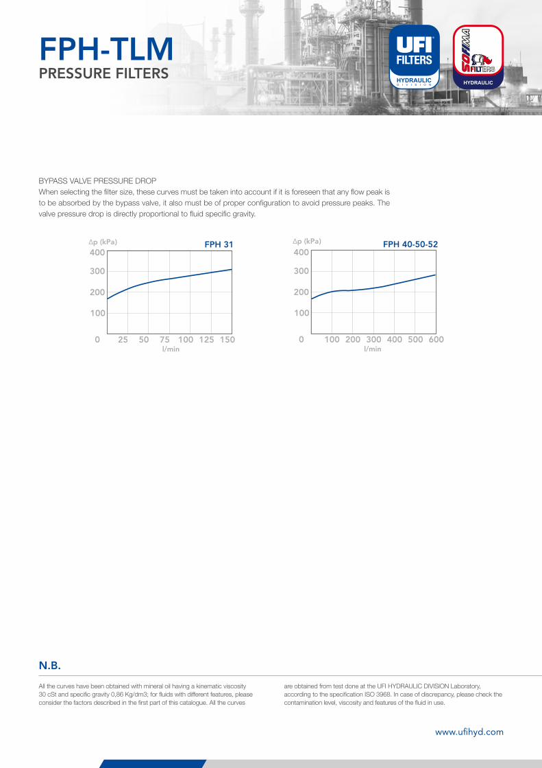
BYPASS VALVE PRESSURE DROPWhen selecting the filter size, these curves must be taken into account if it is foreseen that any flow peak is to be absorbed by the bypass valve, it also must be of proper configuration to avoid pressure peaks. The valve pressure drop is directly proportional to fluid specific gravity.
All the curves have been obtained with mineral oil having a kinematic viscosity 30 cSt and specific gravity 0,86 Kg/dm3; for fluids with different features, please consider the factors described in the first part of this catalogue. All the curves
are obtained from test done at the UFI HYDRAULIC DIVISION Laboratory, according to the specification ISO 3968. In case of discrepancy, please check the contamination level, viscosity and features of the fluid in use.
www.ufihyd.com