Embed Size (px)
Citation preview
HAL Id: hal-01354883https://hal.archives-ouvertes.fr/hal-01354883
Submitted on 22 Aug 2016
HAL is a multi-disciplinary open accessarchive for the deposit and dissemination of sci-entific research documents, whether they are pub-lished or not. The documents may come fromteaching and research institutions in France orabroad, or from public or private research centers.
L’archive ouverte pluridisciplinaire HAL, estdestinée au dépôt et à la diffusion de documentsscientifiques de niveau recherche, publiés ou non,émanant des établissements d’enseignement et derecherche français ou étrangers, des laboratoirespublics ou privés.
FPGA design of EKF block accelerator for 3D visualSLAM
Daniel Tortei, Jonathan Piat, Michel Devy
To cite this version:Daniel Tortei, Jonathan Piat, Michel Devy. FPGA design of EKF block accelerator for 3D visualSLAM. Computers and Electrical Engineering, Elsevier, 2016, �10.1016/j.compeleceng.2016.05.003�.�hal-01354883�

FPGA design of EKF block accelerator for 3D visualSLAM
Daniel Tortei Terteia,b,c, Jonathan Piata,b,∗, Michel Devya,∗
aCNRS, LAAS, 7 avenue du colonel Roche, F-31400 Toulouse, FrancebUniv de Toulouse, UPS, LAAS, F-31400 Toulouse, France
cFaculty of Technical Sciences, Department of Computing and Automation, 21000 NoviSad, Serbia
Abstract
This paper deals with the evaluation of a dedicated architecture to be integratedin an embedded system mounted typically on a micro-aerial vehicle or on smartdevices moved by an operator. This system performs an Extended Kalman Filter(EKF) based visual odometry algorithm: here we present an efficient hardwarearchitecture conceived as a systolic array co-processor for EKF loop acceleration.Due to severe constraints on the power consumption, the real-time performanceand the physical characteristics of the system (compacity, weight...), this al-gorithm is implemented entirely as a System On a programmable Chip (SoC)on the Zynq-7020 device. This heterogeneous platform1 consumes less powerthan a standard microprocessor and provides powerful parallel data processingcapabilities: applying hardware/software (hw/sw) co-design allows to guaranteereal-time throughput with a very low power-per-feature rate.
Keywords: visual EKF-SLAM, SoC, FPGA, co-processor, AHP
1. Introduction
More and more applications require the mobility of a system (a robot, avehicle, a drone, an operator with a tablet or a smartphone,. . . ) equipped withseveral sensors. As soon as such a system moves in an environment, it mustbe endowed with several functions able to provide its position with respect to a5
known reference frame, to detect obstacles in order to avoid collisions (for robotnavigation) or to recognize some known objects (for augmented reality). Ourcontribution concerns only the localization functionality.
Many solutions exists in the litterature, depending on the available sensorymodalities, on the locomotion system, on the a priori knowledge learnt on the en-10
∗CNRS, LAAS, 7 avenue du colonel Roche, F-31400 Toulouse, FranceEmail addresses: [email protected] (Daniel Tortei Tertei), [email protected] (Jonathan
Piat), [email protected] (Michel Devy)1processor + reconfigurable hardware
Preprint submitted to Computers and Electrical Engineering December 13, 2015

vironment, and overall, on the available resources (energy, memory, computingpower . . . ). Many robots (e.g. AGV for industrial environments) and vehicles(e.g. the Google car) are equipped with laser range finders in order to perceivethe environment; here it is proposed to use only vision, i.e. a low-cost sen-sor that could be embedded both on autonomous robots and on smart devices15
moved by humans.A standard Visual Odometry (VO) algorithm is exploited for the localiza-
tion of our system moving in an initially unknown environment. Such a functionbuilds a local map of its environment in the form of positions of landmarks ob-served in images, estimates the local motion made by the system, and then,20
cumulating these motions, estimates the system position with respect to a spe-cific reference frame, generally the initial position when the VO algorithm hasbeen started. Landmarks are presumed to be static. Our mobile system mustbe equipped with a camera and besides it may also have proprioceptive sen-sors in order to give other measurements on the motions: wheel odometry for25
a robot, Inertia Measurement Unit (IMU) for a device worn by an operator orfor a drone. . .
A VO algorithm is very similar to a Visual Simultaneous Localization andMapping approach (VSLAM), but the localization in VO is only estimated froma local map, i.e. a map built on a given horizon time, defined for example by the30
M last acquired images or by the N last detected landmarks; as the localizationis computed from local information, it will be impacted by a drift growing withthe time. With a Visual SLAM algorithm, it is possible to build a global map,even on large environments: if the mobile system returns in a known area andsucceeds in matching observed features with mapped landmarks, cumulative35
errors may be corrected using a loop closure function. VO and VSLAM couldbe based either on Filtering - EKF, Rao-Blackwellized Particle Filter. . . - oron Optimization (global or incremental, iterative or direct. . . ). It is known [1]that the localization given by Optimization methods is more accurate thanfor Filtering ones, but it requires more computing power, and moreover, for40
large environments, the map size could be huge, so that some map managementstrategy has to be applied.
It is the reason why, for systems of limited size, an EKF-based VO algorithmis most often applied for position estimation; moreover it is easier to take intoaccount measurements acquired from asynchronous multiple modalities (several45
cameras, gyros, accelerometers. . . ). Drifts could be corrected from time to timeeither fusing with a priori knowledge given to the system (e.g. Open Street Mapin urban scenes, or a building map for indoor scenes) or with a global positionprovided by a GPS receiver in outdoor environments.
In spite of the increasing computing power on compact embedded system,50
EKF-based VO’s computational complexity still may be too important with onlya software implementation, mainly due to image processing in order to extractfeatures from images and due to large scale matrix-matrix multiplications whenapplying the filter on large state vectors. The real-time constraint for typicalapplications of drones, robots or augmented reality on smart devices, involves55
to update the system position at least at 30Hz(33.33ms). Moreover improving
4
the frequency allows to enter a virtuous cycle: faster is the VO process, easierand more robust is the feature-landmark matching. Another issue is autonomyof the mobile system: standard processors, such as Intel’s quad core i7, consumemuch power, which limits the level of autonomy.60
As a solution to these issues, an embedded system has to be designed whichwould ensure high computational efficiency at low power consumption rates.Modern reconfigurable devices such as Field-Programmable Gate Arrays (FP-GAs) may answer to that question. Their reconfigurable fabric consists of a largenumber of configurable slices, and besides they come with embedded Digital Sig-65
nal Processing (DSP) blocks that can be used for floating point applications.Compared to a standard processor, computationally extensive algorithms maybe parallelized and thus executed several times faster on FPGAs in floatingpoint precision [2]. While Graphical Processing Units (GPUs) also make use ofthe parallelization techniques, the main advantage of FPGAs over both GPUs70
and general purpose central processing units (GPCPUs) remains in significantlylower power consumption.
Embedded GPUs have as well emerged on the market today with similarpower consumption to an FPGA [3]. However, they are designed as to improvecomputational performances on highy demanding image processing applications.75
Thus FPGAs with their algorithm-specific memory management capabilitiesowing to reconfigurability still remain a better choice over embedded GPUs interms of computational efficiency of a custom application.
So this paper presents mainly an efficient SoC architecture for EKF-basedVisual Odometry applications. Using hw/sw co-design we intend to fully port80
VO functionality of our visual SLAM application into embedded domain. Asthis localization algorithm relies on heavy matrix multiplication computations,it is focused on a matrix multiplication accelerator conceived as a systolic arrayco-processor for a hard core ARM CortexA9 processor integrated in a Zynq-7020FPGA.85
1.1. State of the art and motivation
In literature, methods that use Visual SLAM for localization may be clas-sified according to several criteria. Here, only Filtering-based (and specif-ically EKF-based) methods are considered, like in [4, 5], because they aremore adapted for embedded systems with limited resources. Several real-time90
optimization-based methods have been proposed, but either they are not ro-bust [6], or they require a huge computing power [7] or they are specific fordrone applications [8].
Then according to features extracted from images, most methods exploitonly interest points (Harris, SIFT, SURF, BRIEF, ORB. . . ); [9] compares95
several methods proposed for point detection and characterization. Some au-thors [10] exploit heterogeneous landmarks; here only Harris points are used.
Finally according to the sensor configuration, the SLAM function could ac-quire images from monocular, bi-cam or stereovision sensors. These last oneallows to acquire depth images, but only on the sensor vicinity e.g. about 8m.100
5

For a 40cm stereo baseline; 3D landmarks are directly created as Euclideanpoints; points far from the sensor are never considered. Monocular or bearing-only SLAM uses a single camera, so that only 2D features can be observed;from such a feature it is not possible to directly add a 3D landmark in the map;either the initialization of this landmark is delayed [11], waiting for other obser-105
vations from different view points so that a 3D point could be triangulated, orthis initialization could be undelayed using a specific parametrization [12, 13],allowing to exploit landmarks far from the camera, e.g. a peak on the horizonline. Bicam-SLAM combines the two approaches, allowing to create landmarksboth from features matched between the two images, and from features that110
are only perceived by one camera. Here only monocular SLAM with undelayedlandmark initialization is used, so that our method could be executed on anembedded system limited in size and resources - such as a smartphone.
RT-SLAM [14] is a generic Open Source software implementation of ourstate of the art visual bearing-only SLAM algorithm, based only on one cam-115
era to observe the environment, and on an IMU to estimate motions. Themap contains Anchored Homogeneous Point (AHP) landmarks [12] which is aseven-dimensional landmark parametrization. AHP landmark parameterizationis shown to increase filter’s consistency, achieving more robust and accurate lo-calization and mapping. A predefined number of landmarks from the map is120
observed and positions are corrected after each frame acquisition. The choiceis made by applying the one-point Random Sample Consensus (RANSAC) [15].Active search strategy is used for initialization of new ones. Authors [14] reportreal-time performance at 60Hz when having 20 consecutive landmark correc-tions and 5 initializations per EKF loop on an Intel i7 processor (only one core125
is used).C-SLAM [16] presents a C programming language version of RT-SLAM that
implements a simplified SLAM application respecting the DO-178 norm requiredon airborn system. It uses a constant speed robot motion function (no inertiadata) and Inverse-Depth Point landmark parameterization [13]. C-SLAM was130
implemented in [17], on an embedded architecture based on a Virtex5-Virtex6FPGA couple [18]; it runs at 24Hz when having 20 IDP landmarks in the mapand correcting 10 of them in each frame. The advantage gained by this archi-tecture lies on the co-design possibility, with a hardware-level implementationof image processing functions at pixel frequency: Harris point extraction, active135
search strategy . . .Our SLAM is an upgraded version of C-SLAM. It is a monocular SLAM
fusing IMU data for motion prediction, correcting 20 AHP interest points. Ac-tive search strategy is used as well to match the observed points and initializenew ones (5 per frame). This number is obtained by experimentation for one140
application on a robotic platform: C-SLAM behaviour was satisfactory whenhaving set parameters in this manner. IMU data are used in order to reduceuncertainty on landmarks tracking during interest points matching. With this(algorithmic) optimization and for speed issues, one-point RANSAC is replacedby random choice when initializing new points in the map.145
Our approach is as follows: a SLAM algorithm may be divided into two
6

parallel processes [19], namely vision (front-end) and filtering (back-end). Thesetwo processes are executed in pipeline, so that we have a latency of one imageperiod, i.e. the system position is updated at T +2∆T , with landmarks observedin the image acquired at time T . In [20] it is shown that pose estimation can150
make up to 84% of execution time of an EKF-based SLAM algorithm: so, weconcentrate on acceleration of the filtering part of the SLAM. We propose anEKF matrix multiplication SoC that is full-compliant to floating point IEEE754 single precision standard [21] and which permits an EKF loop throughputof 30 Hz with a maximum of 52 AHP points in the map (while observing and155
correcting 20).A power-efficient FPGA-based embedded EKF block accelerator is also pro-
posed in [22]. Their SLAM is a 2D EKF-SLAM application that satisfies real-time constraints (14Hz of execution time in their case) with approximately1.8k landmarks contained in their map which are represented in Euclidean160
parametrization (two-dimensional state size). All of them are observed andcorrected. They do not report on initialization and matching techniques andneither mention whether they use sensors besides a camera. It is the only FPGA-based solution (besides ours) in literature that proposes a visual EKF-SLAMblock embedded accelerator to our knowledge. However, given the dimensional-165
ity of our problem (AHP parametrization) and system complexity (3D mapping,sensors) it is hardly comparable.
Finally, some authors proposed FPGA implementations of matrix multi-plication or inversion, using different strategies [23, 24, 25]; the Parallel in-put/Multiple Output strategy proposed in this last paper, is very similar to our170
systolic array architecture.
1.2. Previous work and contributions
Our previous work on the subject is published in [26] - an EKF accelera-tor which is a PLB peripheral to PPC440 hard core embedded processor on aVirtex5 FPGA. It does not take into account the symmetry in cross-covariance175
matrix - related computations (authors in [22] do not mention that fact either).That impovement leads to significant improvements in design to both latencyand required on-chip memory usage, which will be discussed here.
Contributions of this paper are:180
• Genericity of the accelerator regarding system state size (other sensorsmay be added/removed), feature state size (up to seven-dimensional) andnumber of landmarks (up to 52 AHP points)
• Implementing the new design as an AXI4 bus peripheral on power-efficientZynq-7020 FPGA185
• Taking into account the cross-covariance matrix symmetry to reduce com-putational time (in both software and hardware) and on-chip memorystorage
7

The paper is organized as follows: in Section 2 an analysis of visual EKF-SLAM complexity is given in order to deduce it’s computational bottleneck. In190
Section 3 we address relevant designing issues as to theoretical lower boundson the latency of any multiplication algorithm and the computational modelmapping based on systolic array technique (with regard to their feasibility onan FPGA). Our SoC solution to EKF block acceleration is presented in Section4. In the following section - 5 - it is put under evaluation in terms of latency, re-195
source usage and power consumption. Experimental results (measured latenciesand maximum supported number of AHP landmarks in the map) with futurework are given in Section 6. Finally, Section 7 concludes the paper.
2. Visual EKF-SLAM analysis
Goal of this section is to establish a theoretical background in order to iden-200
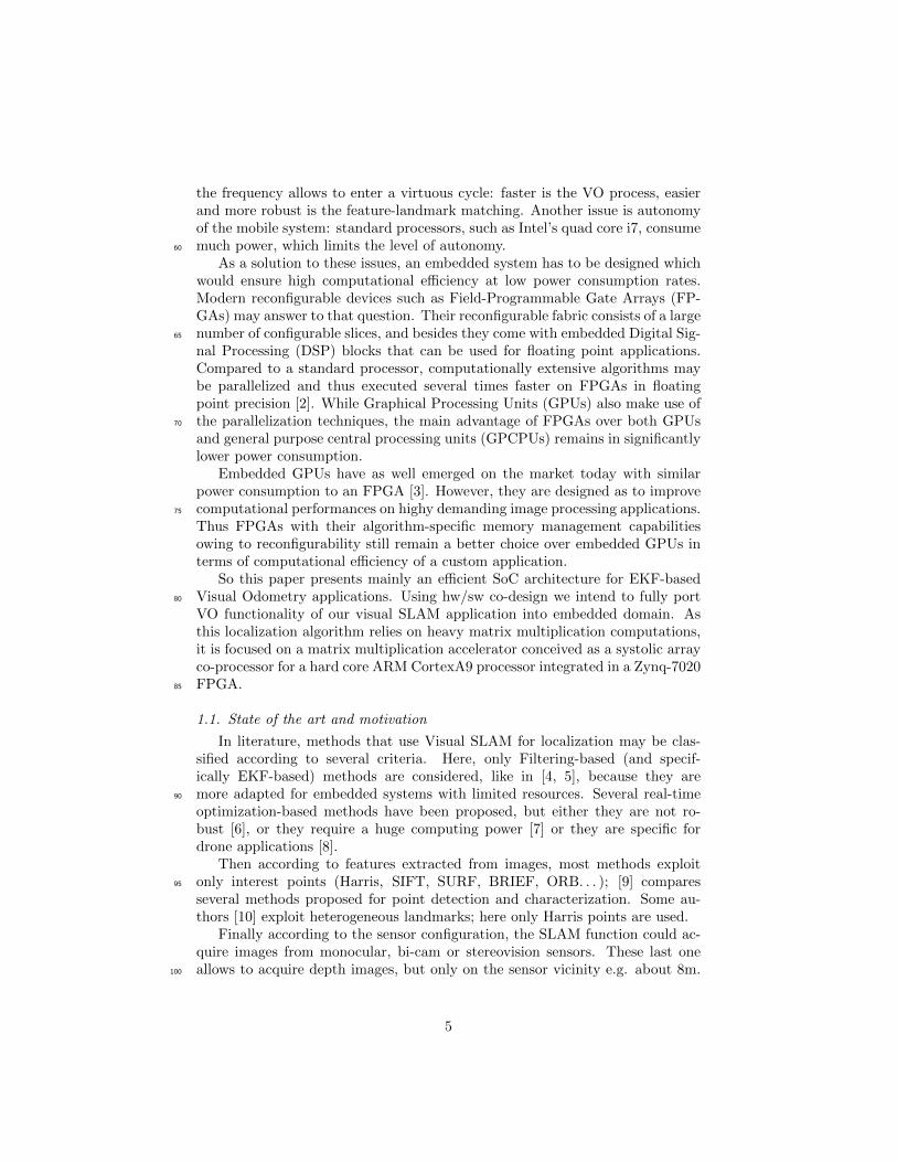
tify the computational bottleneck of an EKF function used for visual SLAMalgorithm in our case. General conclusions may be induced by varying param-eters in Table 1.
A state-space based predictive algorithm based on EKF [12] runs in a three-steps loop: i) prediction of robot’s position from the motion estimates, ii) correc-205
tion of the robot’s and landmarks’ positions with respect to the world referenceframe (by tracking chosen landmarks), and iii) initialization of landmarks [27].
Let us recall that here that our SLAM is implemented without loop closure,so the system position is updated from a local map, with a limited size. Land-marks are removed and replaced by new ones in several situations. (1) They210
are never matched, due to environmental changes (illumination, occlusions . . . ).(2) They have been selected on the surface of a dynamic object. (3) Due to thecamera motion, they are overpassed, so they could not be observed during thenext motions. Possible losses of landmarks may severely influence the quality ofmotion estimation. Thus, it is preferable to have many landmarks memorized215
in the map after loop iii) and to choose a subset of these upon which positioncorrections are going to be made in loop ii). Also, parametrization (dimension-ing) of landmarks plays a significant role in their quality [12], yielding robusterbehaviour with higher landmark state size.
Introducing larger number of higher-dimensional landmarks increases visual220
EKF-SLAM’s computational complexity, having as a consequence in loop ii)larger scale matrix-matrix multiplications.
It is shown that computational requirements for an EKF algorithm dependon the number of features N retained in the map: LEKF = O(N2) [28]. Equa-tions of the EKF are given below2.Prediction loop:
x(t) = f(x(t−1), $(t)) (1)
2In equations 2 and 7 we perform matrix calculations only on P1 and P matrices’ uppertriangles respectively, as the cross-covariance matrix P is symmetrical
8

P(t)1 = F (t)
x P(t−1)1 F (t)T
x + F (t)ω QF (t)T
ω (2)
P(t)2 = F (t)
x P(t−1)2 (3)
Correction loop:
Z(t) = H(t)P(t)3 H(t)T + R (4)
K(t) = P(t)4 H(t)T (Z(t))−1 (5)
x(t) = x(t) + K(t)(y(t) − h(x(t−1))) (6)
P (t+1) = P (t) −K(t)Z(t)K(t)T (7)
After each frame acquisition, the front-end process furnishes interest pointsfound by a feature detector. Active search algorithm is used to find correspon-dences with observed landmarks in the past frame. In our case, we observe225
and search for correspondencies between 20 interest points. Matched pointsare passed through in the camera reference frame. They are afterwards repa-rameterized to richer AHP representation, which is the data type upon whichour Kalman filter works. This information is stored in robot state vector xand is updated in the process within Jacobian (H ) and cross-covariance (P)230
transformations - Table 1.Given this data, an EKF loop is executed as follows: first, a prediction
step is performed in order to update the corresponding elements in P : 1 -3. Matrices P1, P2, P3 and P4 are sub-matrices of the cross covariance matrixP . Secondly, multiple correction loops are run, each with respect to a single235
observed landmark: equations 4 - 7 (in our case 20 times). In correction loopthe filter’s gain is calculated, upon which landmarks’ and robot’s positions arebeing updated (along with the the entire cross-covariance matrix). It is done inequation 6 where IMU odometry and GPS data are integrated in measurementprocess yt (localization). Upon observed, matched and corrected landmarks240
all landmarks in the map are reparameterized from AHP to three-dimensionalEuclidean representation (3D mapping). After correction loops, we are able toreduce the search space for landmarks which we are observing in the followingframe.
In Table 1, N stands for the total number of landmarks retained in the local245
map, d is the dimension of AHP feature state size (which is seven), six is thenumber for GPS and IMU related variables and r is the state-space size of ourrobot (which is nineteen). All twenty landmarks in the map are observed. Fromthat table we deduce Table 2 which shows the total amount of floating-pointoperations that are executed in an EKF block in function of the number of250
retained landmarks N in the visual map.Highest share of the execution time belongs to equation 7. Here, the up-
per triangle of the square P matrix is updated during correction. This fact
9
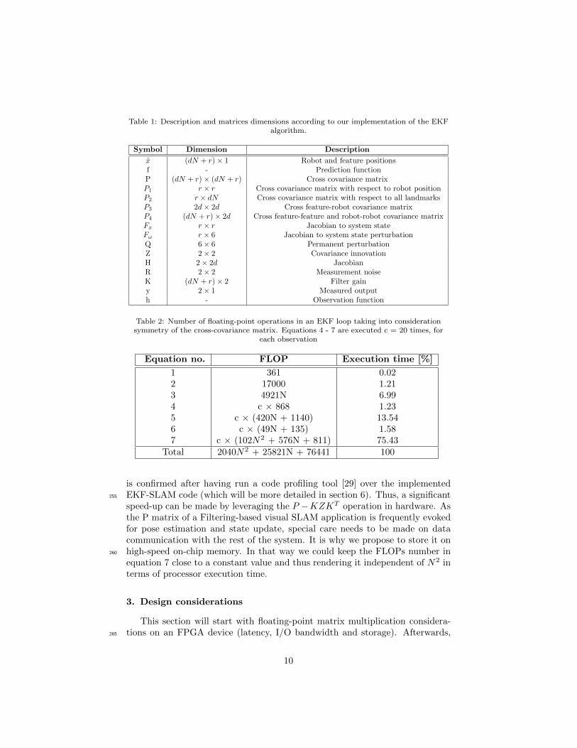
Table 1: Description and matrices dimensions according to our implementation of the EKFalgorithm.
Symbol Dimension Description
x (dN + r)× 1 Robot and feature positionsf - Prediction functionP (dN + r)× (dN + r) Cross covariance matrixP1 r × r Cross covariance matrix with respect to robot positionP2 r × dN Cross covariance matrix with respect to all landmarksP3 2d× 2d Cross feature-robot covariance matrixP4 (dN + r)× 2d Cross feature-feature and robot-robot covariance matrixFx r × r Jacobian to system stateFω r × 6 Jacobian to system state perturbationQ 6× 6 Permanent perturbationZ 2× 2 Covariance innovationH 2× 2d JacobianR 2× 2 Measurement noiseK (dN + r)× 2 Filter gainy 2× 1 Measured outputh - Observation function
Table 2: Number of floating-point operations in an EKF loop taking into considerationsymmetry of the cross-covariance matrix. Equations 4 - 7 are executed c = 20 times, for
each observation
Equation no. FLOP Execution time [%]
1 361 0.022 17000 1.213 4921N 6.994 c × 868 1.235 c × (420N + 1140) 13.546 c × (49N + 135) 1.587 c × (102N2 + 576N + 811) 75.43
Total 2040N2 + 25821N + 76441 100
is confirmed after having run a code profiling tool [29] over the implementedEKF-SLAM code (which will be more detailed in section 6). Thus, a significant255
speed-up can be made by leveraging the P −KZKT operation in hardware. Asthe P matrix of a Filtering-based visual SLAM application is frequently evokedfor pose estimation and state update, special care needs to be made on datacommunication with the rest of the system. It is why we propose to store it onhigh-speed on-chip memory. In that way we could keep the FLOPs number in260
equation 7 close to a constant value and thus rendering it independent of N2 interms of processor execution time.
3. Design considerations
This section will start with floating-point matrix multiplication considera-tions on an FPGA device (latency, I/O bandwidth and storage). Afterwards,265
10
after having introduced a Systolic Array (SA) - based processing system onan FPGA, a processing element (PE) - based computational flow for EKF’sequation 7 will be given.
3.1. Matrix multiplication tradeoffs on FPGAs
On a reconfigurable computing system the main tradeoff is between opti-mal speed and resource utilization. Higher design speeds may be achieved atthe cost of a higher resource usage. On the other hand, the limited number ofconfigurable slices should be used for parallel logic implementation. Consider-ing applications of matrix-matrix multiplication algorithms on programmablehardware of limited size, such as FPGAs, we have to take into account specificconstraints on latency L, total storage size in words M and memory bandwidthrequirement B denoted by number of I/O operations performed in each cycle.Based on a multiplication of two n-squared matrices, authors in [30] explainthese tradeoffs in reference to lower bound on achievable latency:
L ≥ max(L1, L2) ≥ max
(n3
p,
n3
√MB
), (M ≤ n2) (8)
where p is the number of theoretical Processing Elements (PE) that may be270
executed in parallel, L1 is the latency according to computation time and L2 isthe latency dependent on I/O bandwidth. Furthermore, they conclude that anoptimal latency is in this case of order O(n2) when having p = O(n) PEs andM = O(n2) available storage size in words. However, for large scale matrices
the latency is of order O(n3
p ). This is due to the fact that having FPGAs with275
limited resources it is hardly possible to instantiate that many PEs in parallel.A recent work [31] describes an architecture of linear array PEs, similar to thosein [30], but achieving an optimal latency of order O(n2) by exploiting full-duplexcommunication with the host processor (no on-chip memory storage) and at thecost of having it involved during addition of intermediary values. Our design280
will focus on minimal latency of matrix multiplications in EKF equation 7 andon-chip memory storage.
3.2. Notion of systolic arrays on an FPGA
As previously explained, and especially due to available resources on theZynq-7020 device, we chose to optimize the tri-matrix multiplications. Pipelined285
designs present a suitable solution when it comes to allocating resources giventhe specific problem size of our computational model. By identifying compu-tational kernels (i.e. floating point multiplication, addition and subtraction)a problem-specific computational unit called PE may be conceived. Systolicarray (SA) is a form of a pipelined design consisting of a multi-dimensional290
grid of interconnected PEs. Main sequential operation is being optimized (e.g.equation 7 in our case) by restructuring its executional flow so that it may beexecuted on parallel PEs. Besides, a central logic, called Sequencer, controls thedata flow in the grid. Advantage of a SA based computation over sequential ormulti-threaded is that the its grid is able to generate new results after each clock295
11
cycle. In consequence, by exploiting structural properties of an SA we are ableto lower the dimension of the computational model (which is three-dimensionalfor n-squared matrices multiplication) and obtain a better throughput at thecost of more complex control logic of data flows.
Authors in [32] present useful mapping techniques inherent to an FPGA-300
based design. In order to avoid using large number of buffers due to routingissues in a standard matrix-matrix multiplication algorithm, they propose amodified locally recursive version upon which they map control logic onto theirtwo-dimensional SA. However, because of speed issues, PEs are often organizedin a linear list structure - a special case of a one-dimension systolic array in305
which they interconnect by short connection wires. In general, broadcastingdata on a larger grid in an FPGA using a higher dimensional SA structure isnot recommended because of speed degradation due to the size and routingcomplexity of FPGA-based floating point units. In order to achieve efficient lowlatency design we focus our efforts on implementing a 1-D SA.310
3.3. Computational model mapping
The computation model of a one-dimensional SA with four PEs adapted toequation 7 of the EKF block may be described with the following pseudo-code:
Phase I: K × Z
1: for i = 0; i < 7N + 19; i+ = 4 do315
2: (load K matrix, in parallel for x = 0 : 3)3: PEin(x) = {Ki+x,0,Ki+x,1}4: (double-buffer Z matrix)5: PEin(0) = {Z0,0, Z1,0}6: PEin(1) = {Z0,1, Z1,1}320
7: PEin(2) = {Z0,0, Z1,0}8: PEin(3) = {Z0,1, Z1,1}9: (output PE function)
10: PEout(0) = Ki+x,0 × Z0,0 + Ki+x,1 × Z1,0
11: PEout(1) = Ki+x,0 × Z0,1 + Ki+x,1 × Z1,1325
12: PEout(2) = Ki+x,0 × Z0,0 + Ki+x,1 × Z1,0
13: PEout(3) = Ki+x,0 × Z0,1 + Ki+x,1 × Z1,1
14: end for
Phase II: P −KZ ×Kt
1: for i = 0, y = 0; i < 7N + 19; i+ = 4, y+ = 4 do330
2: (load KZ matrix, in parallel for x = 0 : 3)3: PEin(x) = {KZi+x,0,KZi+x,1}4: for j = y; j < 7N + 19; j+ = 4 do5: (load Kt matrix, in parallel for x = 0 : 3)6: PEin(x) = {Kt
0,j+x,Kt1,j+x, Pi+x,j+x}335
7: (output PE function, in parallel for x = 0 : 3)8: PEout(x) = Pi+x,j+x − (KZi+x,0 ×Kt
0,j+x + KZi+x,1 ×Kt1,j+x)
9: end for10: end for
12
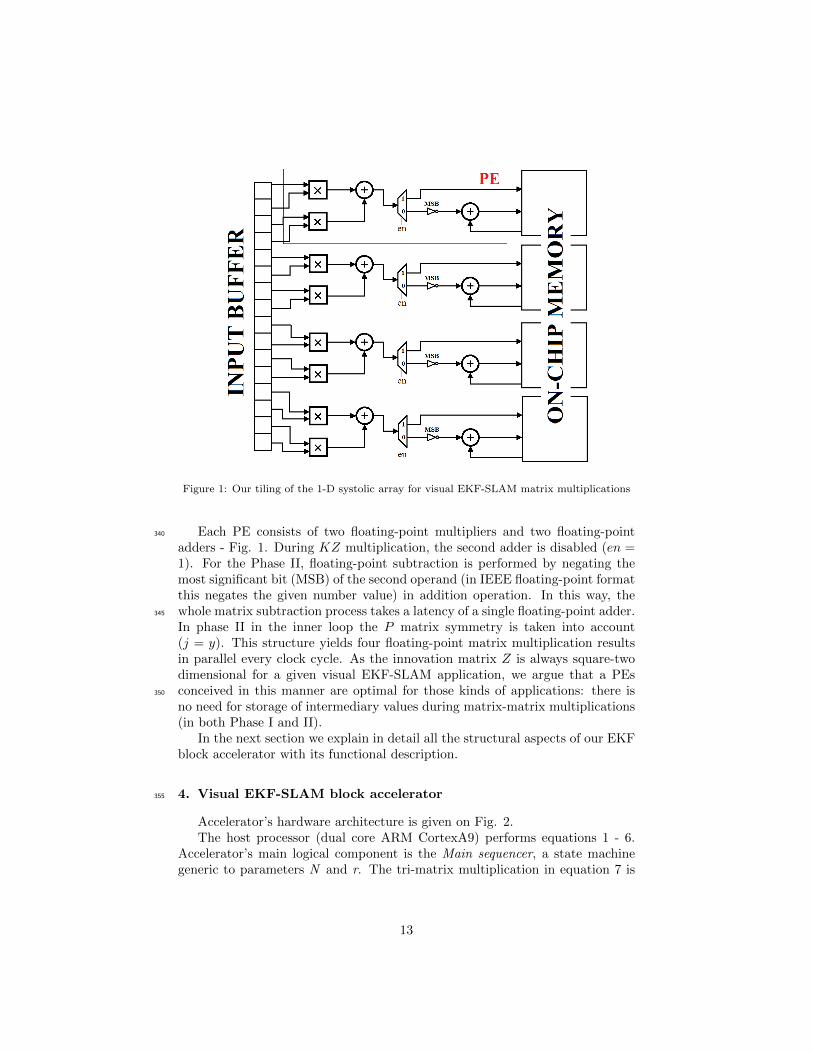
Figure 1: Our tiling of the 1-D systolic array for visual EKF-SLAM matrix multiplications
Each PE consists of two floating-point multipliers and two floating-point340
adders - Fig. 1. During KZ multiplication, the second adder is disabled (en =1). For the Phase II, floating-point subtraction is performed by negating themost significant bit (MSB) of the second operand (in IEEE floating-point formatthis negates the given number value) in addition operation. In this way, thewhole matrix subtraction process takes a latency of a single floating-point adder.345
In phase II in the inner loop the P matrix symmetry is taken into account(j = y). This structure yields four floating-point matrix multiplication resultsin parallel every clock cycle. As the innovation matrix Z is always square-twodimensional for a given visual EKF-SLAM application, we argue that a PEsconceived in this manner are optimal for those kinds of applications: there is350
no need for storage of intermediary values during matrix-matrix multiplications(in both Phase I and II).
In the next section we explain in detail all the structural aspects of our EKFblock accelerator with its functional description.
4. Visual EKF-SLAM block accelerator355
Accelerator’s hardware architecture is given on Fig. 2.The host processor (dual core ARM CortexA9) performs equations 1 - 6.
Accelerator’s main logical component is the Main sequencer, a state machinegeneric to parameters N and r. The tri-matrix multiplication in equation 7 is
13
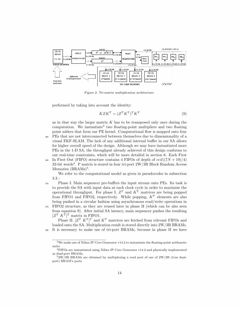
Figure 2: Tri-matrix multiplication architecture.
performed by taking into account the identity:
KZKT = (ZTKT )TKT (9)
as in that way the larger matrix K has to be transposed only once during thecomputation. We instantiate3 two floating-point multipliers and two floatingpoint adders that form our PE kernel. Computational flow is mapped onto fourPEs that are not interconnected between themselves due to dimensionality of a360
visual EKF-SLAM. The lack of any additional internal buffer in our SA allowsfor higher overall speed of the design. Although we may have instantiated morePEs in the 1-D SA, the throughput already achieved of this design conforms toour real-time constraints, which will be more detailed in section 6. Each FirstIn First Out (FIFO) structure contains 4 FIFOs of depth of ceil((7N + 19)/4)365
32-bit words4. P matrix is stored in four tri-port 2W/3R Block Random AccessMemories (BRAMs)5.
We refer to the computational model as given in pseudocodes in subsection3.3 :
Phase I. Main sequencer pre-buffers the input stream onto PEs. Its task is370
to provide the SA with input data at each clock cycle in order to maximize theoperational throughput. For phase I, ZT and KT matrices are being poppedfrom FIFO1 and FIFO2, respectively. While popping, KT elements are alsobeing pushed in a circular fashion using asynchronous read/write operations inFIFO2 structure, as they are reused later in phase II (which can be also seen375
from equation 9). After initial SA latency, main sequencer pushes the resulting[ZT KT ]T matrix in FIFO1.
Phase II. [ZT KT ]T and KT matrices are fetched from relevant FIFOs andloaded onto the SA. Multiplication result is stored directly into 2W/3R BRAMs.It is necessary to make use of tri-port BRAMs, because in phase II we have380
3We make use of Xilinx IP Core Generator v14.2 to instantiate the floating-point arithmeticunits.
4FIFOs are instantiated using Xilinx IP Core Generator v14.2 and physically implementedas dual-port BRAMs.
52W/3R BRAMs are obtained by multiplexing a read port of one of 2W/2R (true dual-port) BRAM’s ports
14

Figure 3: Our SoC implementation of the 3D EKF-SLAM application
simultaneous read and write operations with different addresses from/to on-chip memory (e.g. the elements of P are simultaneously fetched and stored theinner for loop in pseudocode lines 6 and 8). As one 1W/1R port is used forthe store operation, the multiplexed 1R port is used for fetch operation. Thethird 1W/1R address line functioanlity rests for the host processor (execution385
of other equations in EKF block that require parts of P matrix).On Figure 3 we present the entire Zynq-7020 SoC with our co-processor re-
ferred to as Intellectual Property (IP). It is attached as an Advanced eXtensibleInterface (AXI) peripheral to a dual-core ARM processor6. The cross-covariancematrix P makes in total ((7N + r)(7N + r) + (7N + r))2 bytes. Because it is390
stored entirely in the on-chip memory, pointer values are pre-set in programmemory on each corresponding element in the on-chip memory so the host mayaccess elements in P.
Communication with the host processor unfolds in three simple steps:
1. ARM loads matrices K and Z onto a fast on-chip memory (input buffer)395
via axiinterconnect bus from the external DDR3 SDRAM and sends a
6The system is designed using Xilinx Platform Studio v14.2
15
”go” signal to the IP.
2. Our co-processor performs operations in equation 7, during which host isable to perform other tasks which don’t evolve state estimation or update.During phase II, main sequencer stores the subtracted four results into400
four BRAMs, each containing the (4s + j)mod4 th element, where s isthe current store cycle count and j is the number of the current row in a(7N + 19)mod4 cycle.
3. Co-processor asserts a ”done multiplication” signal. By polling, the hostverifies end of the execution of the operations in equation 7.405
5. Design evaluation
In this section we give a theoretical estimate on developed multiplier’s la-tency which is later going to be compared with experimental results (in Section6) in order to evaluate the efficiency of the proposed SA-based design in termsof speed of execution. Afterwards we present an overview over resource and410
power consumption of the entire co-processor on the FPGA.
5.1. Multiplier Latency
After the analysis in section 3 we have:
L > L0 + L1 + L2 (10)
L1 > max
(n
p,
n√nB
)(11)
L2 > max
(n2
2p,
n2
√2n2B
)(12)
L1 and L2 are latencies after ZTKT and (ZTKT )TKT matrix multiplicationsrespectively. L0 is the latency due to processor-IP communication bandwidth.Concerning the matrix multiplication part, we have M1 =
√n and M2 =
√n2
415
because we have loaded all the corresponding matrices into two FIFO structuresso that they could be fetched at each clock cycle. Furthermore, B = 20 owingto buffered input data and parallel storing of the results. Thus we are able to
deduce that L1 > 7N+r4 and L2 > (7N+r)2
8 as we have p = 4 processing elements.All delays greater than L1+L2 clock cycles are due to L0 and because of pushing420
the two input matrices onto FIFOs.
16
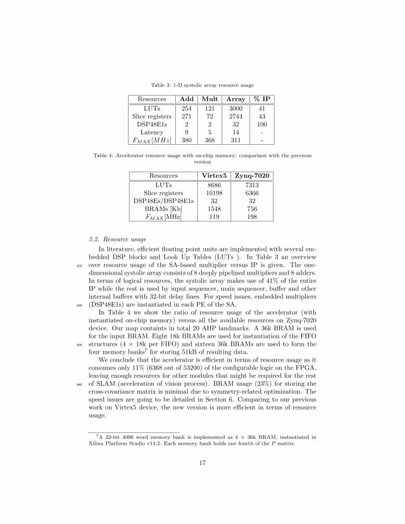
Table 3: 1-D systolic array resource usage
Resources Add Mult Array % IP
LUTs 254 121 3000 41Slice registers 271 72 2744 43
DSP48E1s 2 2 32 100Latency 9 5 14 -
FMAX [MHz] 380 368 311 -
Table 4: Accelerator resource usage with on-chip memory: comparison with the previousversion
Resources Virtex5 Zynq-7020
LUTs 8686 7313Slice registers 10198 6366
DSP48Es/DSP48E1s 32 32BRAMs [Kb] 1548 756FMAX [MHz] 119 198
5.2. Resource usage
In literature, efficient floating point units are implemented with several em-bedded DSP blocks and Look Up Tables (LUTs ). In Table 3 an overviewover resource usage of the SA-based multiplier versus IP is given. The one-425
dimensional systolic array consists of 8 deeply pipelined multipliers and 8 adders.In terms of logical resources, the systolic array makes use of 41% of the entireIP while the rest is used by input sequencer, main sequencer, buffer and otherinternal buffers with 32-bit delay lines. For speed issues, embedded multipliers(DSP48E1s) are instantiated in each PE of the SA.430
In Table 4 we show the ratio of resource usage of the accelerator (withinstantiated on-chip memory) versus all the available resources on Zynq-7020device. Our map containts in total 20 AHP landmarks. A 36k BRAM is usedfor the input BRAM. Eight 18k BRAMs are used for instantiation of the FIFOstructures (4 × 18k per FIFO) and sixteen 36k BRAMs are used to form the435
four memory banks7 for storing 51kB of resulting data.We conclude that the accelerator is efficient in terms of resource usage as it
consumes only 11% (6368 out of 53200) of the configurable logic on the FPGA,leaving enough resources for other modules that might be required for the restof SLAM (acceleration of vision process). BRAM usage (23%) for storing the440
cross-covariance matrix is minimal due to symmetry-related optimization. Thespeed issues are going to be detailed in Section 6. Comparing to our previouswork on Virtex5 device, the new version is more efficient in terms of resourceusage.
7A 32-bit 4096 word memory bank is implemented as 4 × 36k BRAM, instantiated inXilinx Platform Studio v14.2. Each memory bank holds one fourth of the P matrix
17
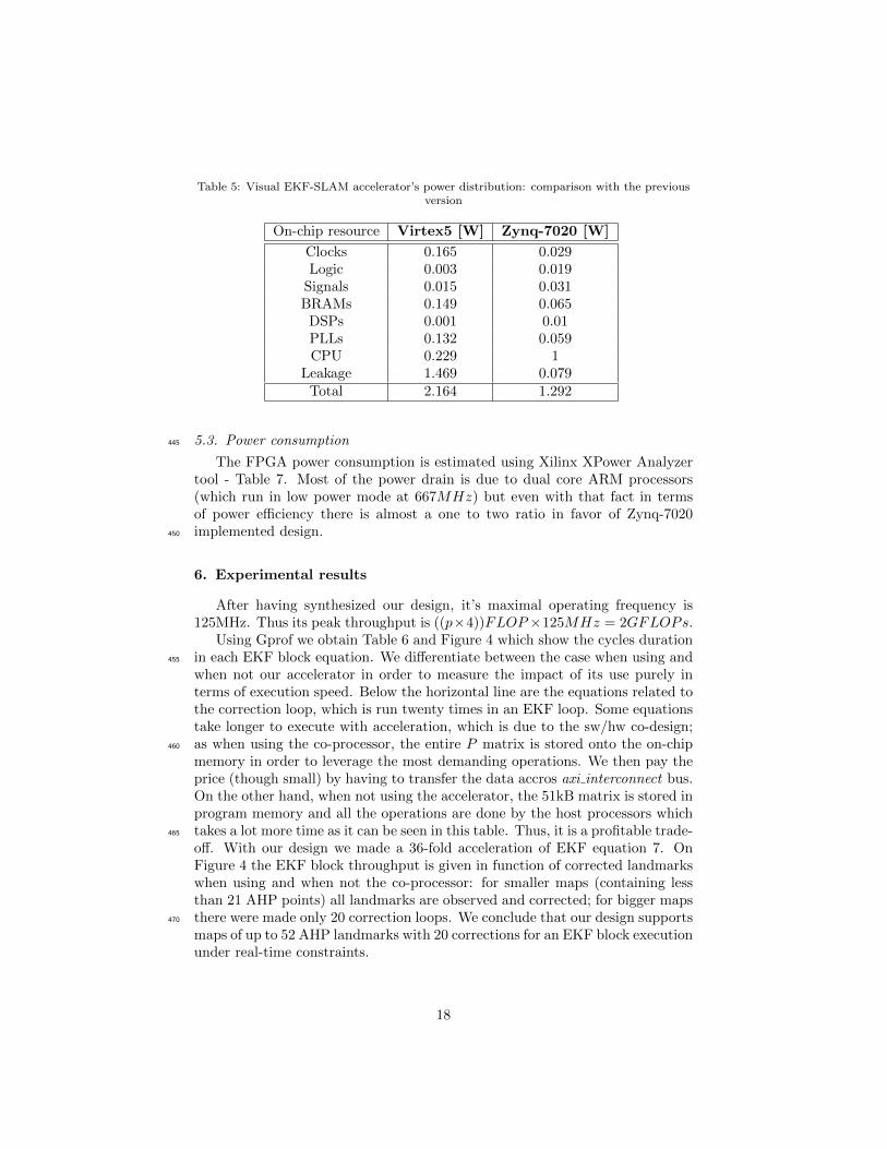
Table 5: Visual EKF-SLAM accelerator’s power distribution: comparison with the previousversion
On-chip resource Virtex5 [W] Zynq-7020 [W]
Clocks 0.165 0.029Logic 0.003 0.019
Signals 0.015 0.031BRAMs 0.149 0.065
DSPs 0.001 0.01PLLs 0.132 0.059CPU 0.229 1
Leakage 1.469 0.079Total 2.164 1.292
5.3. Power consumption445
The FPGA power consumption is estimated using Xilinx XPower Analyzertool - Table 7. Most of the power drain is due to dual core ARM processors(which run in low power mode at 667MHz) but even with that fact in termsof power efficiency there is almost a one to two ratio in favor of Zynq-7020implemented design.450
6. Experimental results
After having synthesized our design, it’s maximal operating frequency is125MHz. Thus its peak throughput is ((p×4))FLOP×125MHz = 2GFLOPs.
Using Gprof we obtain Table 6 and Figure 4 which show the cycles durationin each EKF block equation. We differentiate between the case when using and455
when not our accelerator in order to measure the impact of its use purely interms of execution speed. Below the horizontal line are the equations related tothe correction loop, which is run twenty times in an EKF loop. Some equationstake longer to execute with acceleration, which is due to the sw/hw co-design;as when using the co-processor, the entire P matrix is stored onto the on-chip460
memory in order to leverage the most demanding operations. We then pay theprice (though small) by having to transfer the data accros axi interconnect bus.On the other hand, when not using the accelerator, the 51kB matrix is stored inprogram memory and all the operations are done by the host processors whichtakes a lot more time as it can be seen in this table. Thus, it is a profitable trade-465
off. With our design we made a 36-fold acceleration of EKF equation 7. OnFigure 4 the EKF block throughput is given in function of corrected landmarkswhen using and when not the co-processor: for smaller maps (containing lessthan 21 AHP points) all landmarks are observed and corrected; for bigger mapsthere were made only 20 correction loops. We conclude that our design supports470
maps of up to 52 AHP landmarks with 20 corrections for an EKF block executionunder real-time constraints.
18

Table 6: EKF equations cycles measured with 125 MHz counter
Equation no◦ Accelerator No accelerator
1 6700 67002 89000 866003 507000 5000004 270 2705 18800 180006 7500 75007 6100 220000
Figure 4: Measured EKF block throughput.
In Table 7 power per feature benchmarking is presented for our 3D EKFSLAM application (with 20 landmarks corrections). Maximum number of land-marks is the number of AHP landmarks retained in the SLAM’s map that475
permit 30Hz EKF block period.
6.1. Measured multiplication latencies
For twenty landmark observations: the input sequencer takes 2×2+159×2 =322 clock cycles and the computational latency is L1 + L2 ∼ 3752 clock cycles8
which leaves us for the host processors-accelerator communication latency L0 ∼480
8Validated by ChipScope Pro Analyzer
19

Table 7: Power per feature metric for visual EKF-SLAM with AHP points
Hardware platform max. no. landmarks Power [W] Power/feature
Intel i3 (2 × 1.8 GHz, 4GB RAM ) ∼ 100 34 0.34Virtex5 SoC (400 MHz) 45 2.164 0.048
Zynq-7020 SoC (2 × 667 MHz) 52 1.292 0.024
6100−4074 = 2026 clock cycles. Computational latency is close to the predictedvalue in subsection 5.1 from which we confirm that the desing performs close toits theoretical optimum.
6.2. Future work
Having reduced the cycles number in EKF correction loop, new bottlenecks485
of the design become equations in the prediction loop : Eq. 2 and Eq. 3 (seeTable 6). Besides VHDL code optimization for higher execution speeds (FMAX),the focus of the future work is to exploit the existing processing power (the PEs)and FIFO structures (FIFO1 and FIFO2) so as to upgrade:
1. Structure of the SA to become a two-dimensional array by interconnecting490
existing PEs and
2. Its control logic.
7. Conclusion
In this paper we proposed an accelerator for a visual 3D EKF-SLAM appli-cation (without loop closure) that uses high-dimensional landmark parametriza-495
tion for mobile platform localization. It is designed as an SoC on a Zynq-7020device, yielding high performance metrics: minimal latency (close to theoreti-cal optimum), low resource usage (11% of LUTs and 23% of on-chip memory)and low power per feature (24mW per single seven-dimensional landmark statesize). It allows 30Hz throughput of an EKF block while containing 52 AHP500
parameterized points in SLAM’s local map, which is more than a three-fold im-provement in comparison with the application running purely on ARM hosts.
As it consumes small amounts of resources, other accelerators (i.e. for featuredetection and/or feature matching) or soft-core processors (i.e. MicroBlaze) maybe implemented on the FPGA.505
These characteristics make our design suitable for implementation on embed-ded systems of limited size, memory and computational resources which requirereliable localization functionality, such as micro-aerial vehicles and smartphones.
Acknowledgement
This work has been co-authored by Daniel Tortei Tertei, paid by the FUI-510
AAP14 project AIR-COBOT, co-funded by BPI France, FEDER and the Midi-Pyrenees region.
20
References
[1] H. Strasdat, J. Montiel, A. Davison, Real-time monocular slam: Why fil-ter?, in: Proc. of IEEE International Conference on Robotics and Automa-515
tion (ICRA), 2010.
[2] K. Underwood, K. Hemmert, Closing the Gap: CPU and FPGA Trendsin Sustainable Floating-Point BLAS Performance, in: Proc. IEEE Symp.Field-Programmable Custom Computing Machines, 2004.
[3] NVIDIA, NVIDIA Jetson TX1 Supercomputer-on-Module Drives Next520
Wave of Autonomous Machines (2015).URL http://devblogs.nvidia.com/parallelforall/
nvidia-jetson-tx1-supercomputer-on-module-drives-next-wave-of-autonomous-machines/
[4] G. Zhang, P. Vela, Optimally observable and minimal cardinality monoc-ular slam, in: Proc. IEEE International Conference on Robotics and Au-525
tomation (ICRA), 2015.
[5] G. Bresson, T. Feraud, R. Aufrere, P. Checchin, R. Chapuis, Real timemonocular slam with low memory requirements, IEEE Intelligent Trans-portation Systems Transactions and Magazine.
[6] G. Klein, D. Murray, Parallel tracking and mapping for small AR530
workspaces, in: Proc. 6th IEEE and ACM Int. Symp. on Mixed and Aug-mented Reality, IEEE Computer Society, 2007.
[7] R. Mur-Artal, J. Montiel, J. Tardos, Orb-slam: a versatile and accuratemonocular slam system, IEEE Transactions on Robotics (ITRO).
[8] C. Forster, M. Pizzoli, D. Scaramuzza, Svo: Fast semi-direct monocular535
visual odometry, in: Proc. IEEE International Conference on Robotics andAutomation (ICRA), 2014.
[9] G. Zhang, P. Vela, Good features to track for visual slam, in: Proc. IEEEInternational Conference on Computer Vision and Pattern Recognition(CVPR), 2015.540
[10] T. Vidal-Calleja, C. Berger, J. Sola, S. Lacroix, Large scale multiple robotvisual mapping with heterogeneous landmarks in semi-structured terrain,Robotics and Autonomous Systems 59 (9) (2011) 654–674.
[11] A. J. Davison, Real-time simultaneous localisation and mapping with asingle camera, in: Proc. Ninth IEEE International Conference on Computer545
Vision - Volume 2, ICCV ’03, 2003.
[12] J. Sola, T. Vidal-Calleja, J. Civera, J. Montiel, Impact of landmarkparametrization on monocular EKF-SLAM with points and lines, Inter-national Journal on Computer Vision.
21
[13] J. Montiel, Unified inverse depth parametrization for monocular slam., in:550
Proc. Robotics: Science and Systems (RSS), 2006.
[14] C. Roussillon, A. Gonzalez, J. Sola, J. Codol, N. Mansard, S. Lacroix,M. Devy, RT-SLAM : A Generic and Real-Time Visual SLAM Implemen-tation., in: 8th International Conference on Computer Vision Systems,Sophia Antipolis (France), 2011.555
[15] M. Fischler, R. Bolles, Random Sample Consensus: A Paradigm for ModelFitting with Applications to Image Analysis and Automated Cartography,Communications of the ACM.
[16] A. Gonzalez, J. Codol, M. Devy, A C-embedded Algorithm for Real-TimeMonocular SLAM., in: 18th International Conference on Electronics, Cir-560
cuits and Systems, Beyrouth, Liban, 2011.
[17] D. Botero, J. Piat, M. Devy, J. Boizard, An fpga accelerator for multispec-tral vision-based ekf-slam, Proc. IROS Workshop on Smart CAmeras forroBOTic applications (SCaBot), Vilamoura (Portugal).
[18] Xilinx, All Programmable FPGAs (2011).565
URL http://www.xilinx.com/content/xilinx/en/products/
silicon-devices/fpga/
[19] J. Piat, J. Piat, D. Marquez-Gamez, M. Devy, Embedded vision-basedSLAM: A model-driven approach, in: Proc. Conference on Design andArchitectures for Signal and Image Processing (DASIP), 2013.570
[20] B. Vincke, A. Elouardi, A. Lambert, Implementation of EKF-SLAM on aMulti-Core Embedded System, in: IECON, Montreal, Canada, 2012.
[21] IEEE Standard for Binary Floating-Point Arithmetic, IEEE.
[22] V. Bonato, E. Marques, G. Constantinides, A Floating-Point ExtendedKalman Filter Implementation for Autonomous Mobile Robots, Journal of575
VLSI Signal Processing.
[23] E. Sarraf, M. Ahmed-Ouameur, D. Massicotte, Fpga design and imple-mentation of direct matrix inversion based on steepest descent method,in: Proc. 50th Midwest Symposium on Circuits and Systems (MWSCAS),2007.580
[24] S. Qasim, A. Telba, A. AlMazroo, Fpga design and implementation ofmatrix multiplier architectures for image and signal processing applications,International Journal of Computer Science and Network Security (IJCSNS)10 (2).
[25] S. Tiwari, S. Singh, N. Meena, Fpga design and implementation of matrix585
multiplication architecture by ppi-mo techniques, International Journal ofComputer Applications 80 (1) (2013) 19–22.
22

[26] D. T. Tertei, J. Piat, M. Devy, FPGA design and implementation of a ma-trix multiplier based accelerator for 3D EKF SLAM, in: Proc. Conferenceon ReConFigurable Computing and FPGAs (ReConFig), 2014.590
[27] J. Sola, A. Monin, M. Devy, T. Lemaire, Undelayed initialization in bearingonly slam., in: Proc. of IEEE/RSJ International Conference on IntelligentRobots and Systems (IROS), 2005, pp. 2499–2504.
[28] S. Thrun, W. Burgard, D. Fox, Probabilistic Robotics, MIT Press.
[29] J. Spivey, Fast, accurate call graph profiling, Oxford University Computing595
Laboratory.
[30] L. Zhuo, V. Prasanna, Scalable and Modular Algorithms for Floating-PointMatrix Multiplication on Reconfigurable Computing Systems, in: IEEETransactions on Parallele and Distributed Systems, Vol. 18, No. 4, 2007.
[31] Z. Jovanovi, V. Milutinovi, FPGA accelerator for floating-point matrix mul-600
tiplication, IET Computers and Digital Techniques.
[32] A. Castillo-Atoche, D. Torres-Roman, Y. Shkvarko, Towards real time im-plementation of reconstructive signal processing algorithms using systolicarray coprocessors, Journal of Systems Architecture (2010) 327–339.
23


![FPGA Architectures for Dense SLAM · 2019. 8. 6. · [5] Fang, Weikang, et al. "FPGA-based ORB feature extraction for real-time visual SLAM." 2017 International Conference on Field](https://img.pdfslide.us/doc/110x75/600064f3b42e511aab0a7309/fpga-architectures-for-dense-slam-2019-8-6-5-fang-weikang-et-al-fpga-based.jpg)


![SLAM for Dummies presentation.ppt [Read-Only]web.mit.edu/16.412j/www/html/Final Projects/SLAM... · Landmark policies Validation gate EKF odometry update EKF re-observation EKF new](https://img.pdfslide.us/doc/110x75/5f42fa94cd991c716e020e19/slam-for-dummies-read-onlywebmitedu16412jwwwhtmlfinal-projectsslam.jpg)