Embed Size (px)
Citation preview

FPGA Design Challenge Techkriti 2013
Digital Logic Design using Verilog
Part 2
By
Neeraj Kulkarni
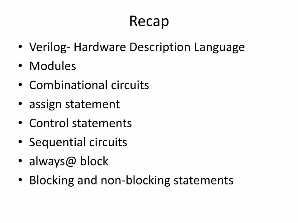
Recap
• Verilog- Hardware Description Language
• Modules
• Combinational circuits
• assign statement
• Control statements
• Sequential circuits
• always@ block
• Blocking and non-blocking statements
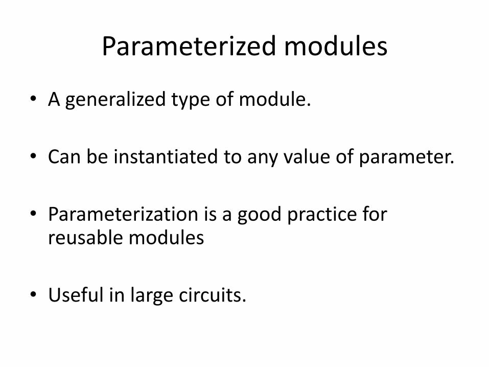
Parameterized modules
• A generalized type of module.
• Can be instantiated to any value of parameter.
• Parameterization is a good practice for reusable modules
• Useful in large circuits.
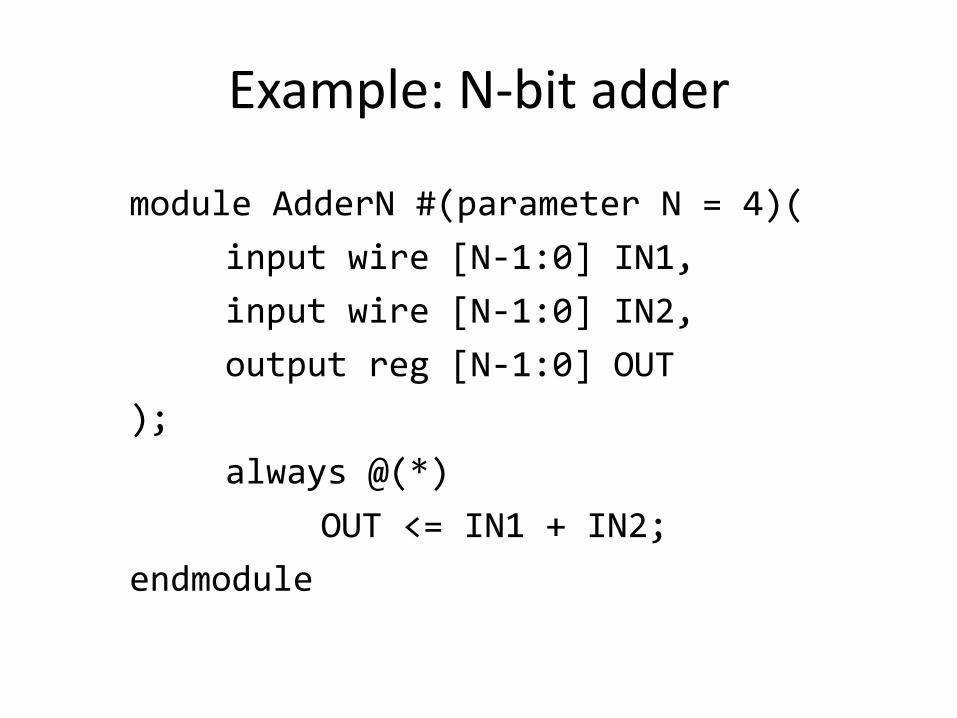
Example: N-bit adder
module AdderN #(parameter N = 4)(
input wire [N-1:0] IN1,
input wire [N-1:0] IN2,
output reg [N-1:0] OUT
);
always @(*)
OUT <= IN1 + IN2;
endmodule
Modular Circuits
• Time to connect the “black boxes” together
• A modular circuit is one where sub-modules are initialized with interconnects to form even a larger circuit.
• Each sub-module resides in its own Verilog file. A sub-module may use another sub-module in its circuit.
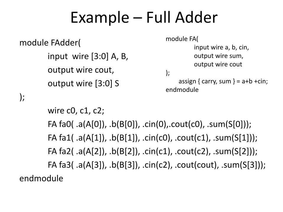
Example – Full Adder
module FAdder(
input wire [3:0] A, B,
output wire cout,
output wire [3:0] S
);
wire c0, c1, c2;
FA fa0( .a(A[0]), .b(B[0]), .cin(0),.cout(c0), .sum(S[0]));
FA fa1( .a(A[1]), .b(B[1]), .cin(c0), .cout(c1), .sum(S[1]));
FA fa2( .a(A[2]), .b(B[2]), .cin(c1), .cout(c2), .sum(S[2]));
FA fa3( .a(A[3]), .b(B[3]), .cin(c2), .cout(cout), .sum(S[3]));
endmodule
module FA( input wire a, b, cin, output wire sum, output wire cout ); assign { carry, sum } = a+b +cin; endmodule
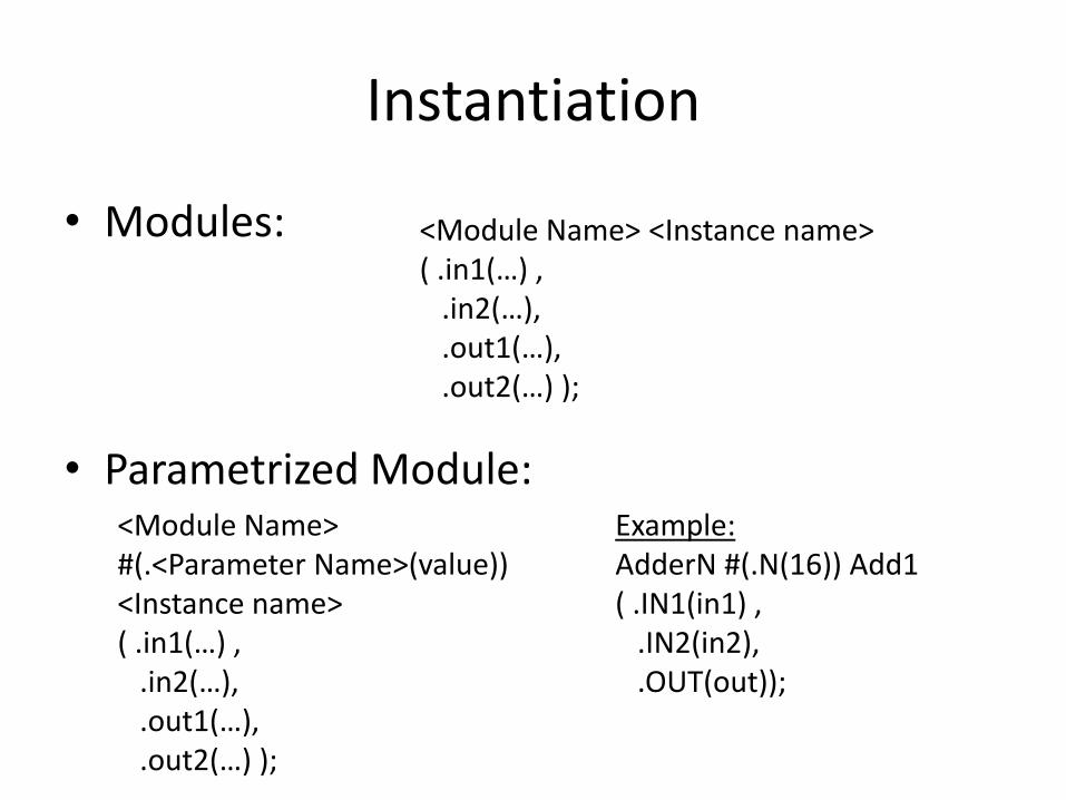
Instantiation
• Modules:
• Parametrized Module:
<Module Name> <Instance name> ( .in1(…) , .in2(…), .out1(…), .out2(…) );
<Module Name> #(.<Parameter Name>(value)) <Instance name> ( .in1(…) , .in2(…), .out1(…), .out2(…) );
Example: AdderN #(.N(16)) Add1 ( .IN1(in1) , .IN2(in2), .OUT(out));
Points to Note
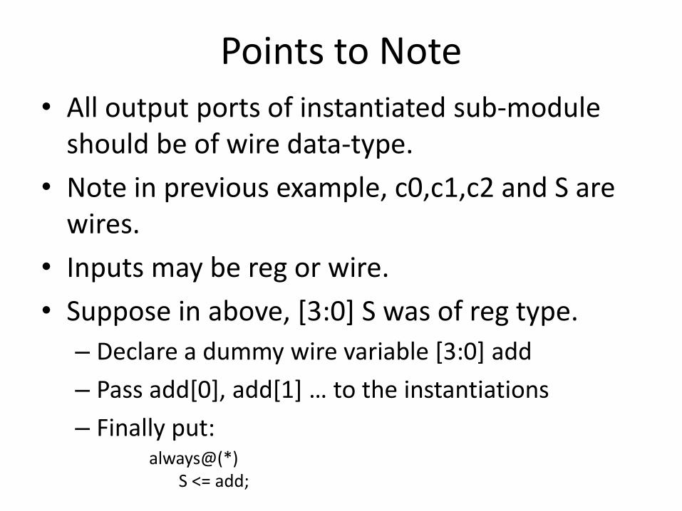
• All output ports of instantiated sub-module should be of wire data-type.
• Note in previous example, c0,c1,c2 and S are wires.
• Inputs may be reg or wire.
• Suppose in above, [3:0] S was of reg type.
– Declare a dummy wire variable [3:0] add
– Pass add[0], add[1] … to the instantiations
– Finally put: always@(*) S <= add;
Test Bench
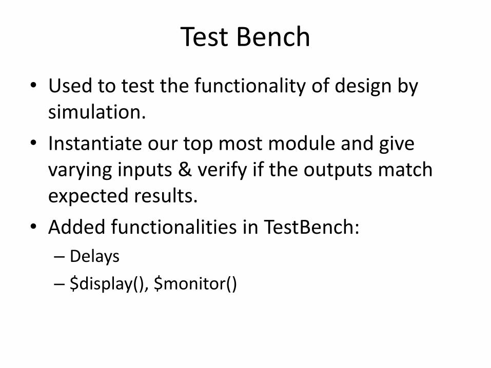
• Used to test the functionality of design by simulation.
• Instantiate our top most module and give varying inputs & verify if the outputs match expected results.
• Added functionalities in TestBench:
– Delays
– $display(), $monitor()
Delays
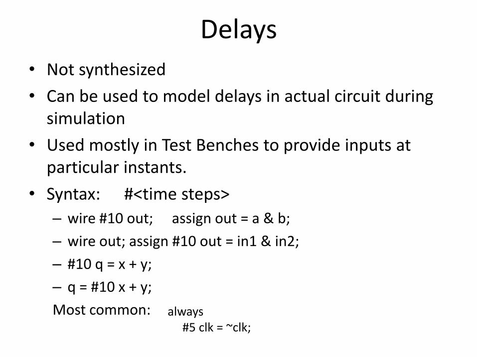
• Not synthesized
• Can be used to model delays in actual circuit during simulation
• Used mostly in Test Benches to provide inputs at particular instants.
• Syntax: #<time steps>
– wire #10 out; assign out = a & b;
– wire out; assign #10 out = in1 & in2;
– #10 q = x + y;
– q = #10 x + y;
Most common: always #5 clk = ~clk;
More Features
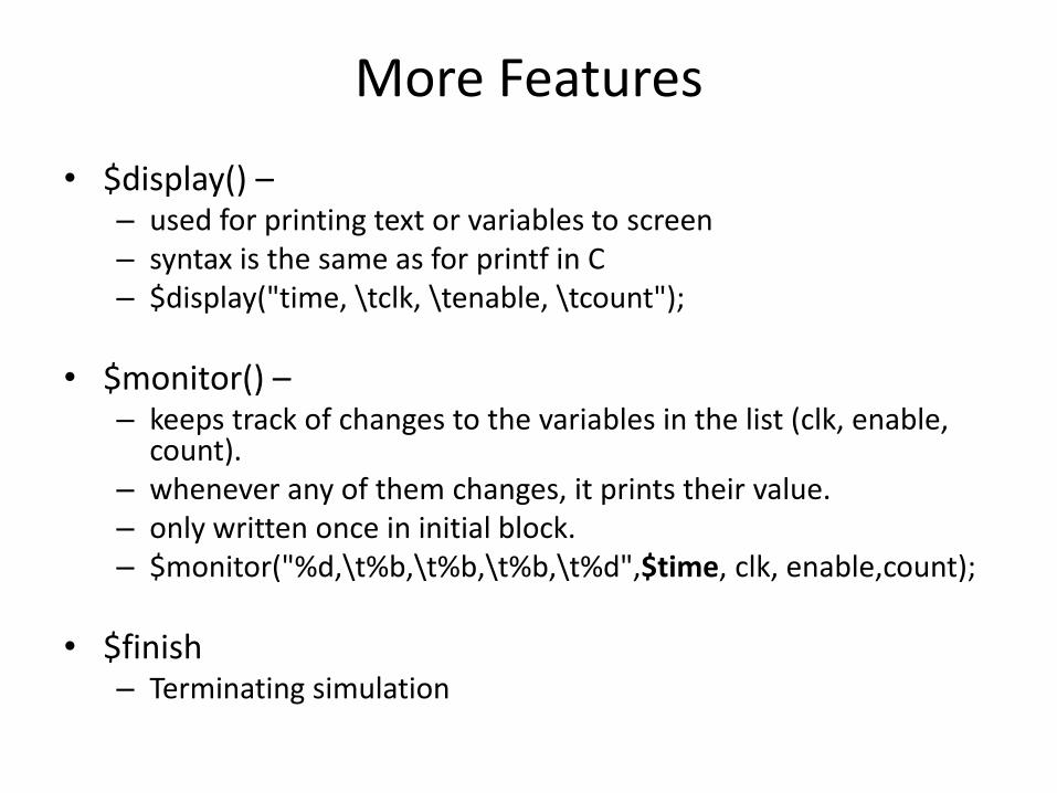
• $display() – – used for printing text or variables to screen – syntax is the same as for printf in C – $display("time, \tclk, \tenable, \tcount");
• $monitor() – – keeps track of changes to the variables in the list (clk, enable,
count). – whenever any of them changes, it prints their value. – only written once in initial block. – $monitor("%d,\t%b,\t%b,\t%b,\t%d",$time, clk, enable,count);
• $finish – Terminating simulation
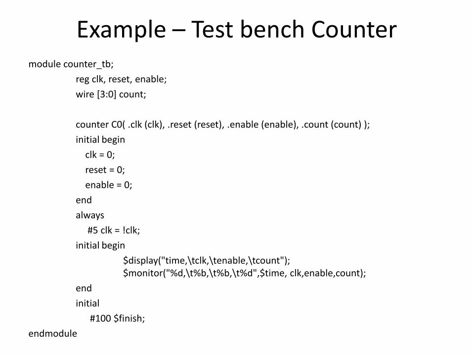
Example – Test bench Counter module counter_tb;
reg clk, reset, enable;
wire [3:0] count;
counter C0( .clk (clk), .reset (reset), .enable (enable), .count (count) );
initial begin
clk = 0;
reset = 0;
enable = 0;
end
always
#5 clk = !clk;
initial begin
$display("time,\tclk,\tenable,\tcount"); $monitor("%d,\t%b,\t%b,\t%d",$time, clk,enable,count);
end
initial
#100 $finish;
endmodule

Gaussian Random Number Generator
FPGA Design Challenge Problem Statement
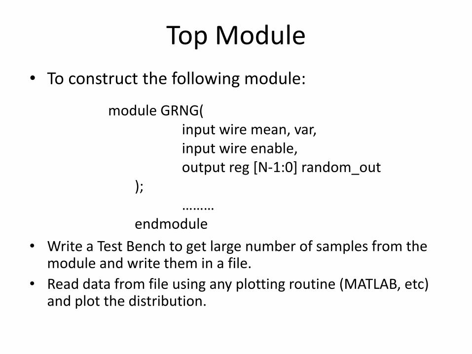
Top Module
• To construct the following module:
• Write a Test Bench to get large number of samples from the module and write them in a file.
• Read data from file using any plotting routine (MATLAB, etc) and plot the distribution.
module GRNG( input wire mean, var, input wire enable, output reg [N-1:0] random_out ); ……… endmodule
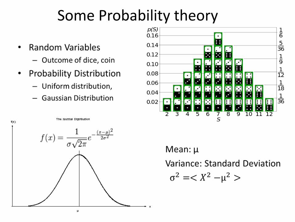
Some Probability theory
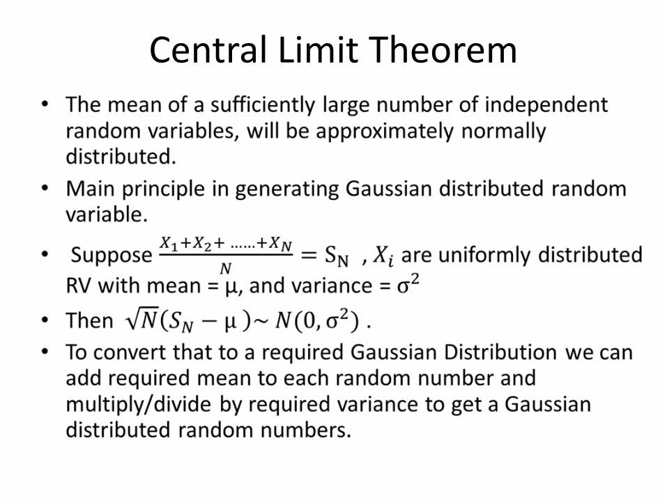
Central Limit Theorem
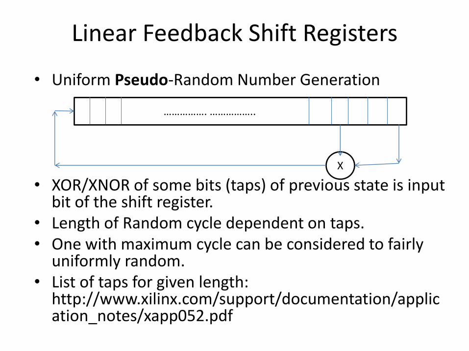
Linear Feedback Shift Registers
• Uniform Pseudo-Random Number Generation
• XOR/XNOR of some bits (taps) of previous state is input bit of the shift register.
• Length of Random cycle dependent on taps. • One with maximum cycle can be considered to fairly
uniformly random. • List of taps for given length:
http://www.xilinx.com/support/documentation/application_notes/xapp052.pdf
……………. ……………..
X

Note
• The approach mentioned above is one of the many possible solutions to the problem statement.
• You should search more and come up with a better solution.
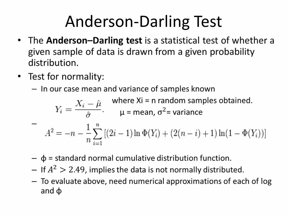
Anderson-Darling Test
Extra Task
• Only if you complete the compulsory task
• Write an encoder and decoder for LDPC codes.
• Add the GRN (Noise) to output of encoder and pass it as input to decoder.
• Do it for large number samples, and get number of errors.
• Repeat for different values of SNR and plot the BER curve for the system.

Questions?